US7940207B1 - Modular design for a fill-level-radar antenna system - Google Patents
Modular design for a fill-level-radar antenna systemDownload PDFInfo
- Publication number
- US7940207B1 US7940207B1US12/547,926US54792609AUS7940207B1US 7940207 B1US7940207 B1US 7940207B1US 54792609 AUS54792609 AUS 54792609AUS 7940207 B1US7940207 B1US 7940207B1
- Authority
- US
- United States
- Prior art keywords
- module
- antenna
- horn
- housing
- modular system
- Prior art date
- Legal status (The legal status is an assumption and is not a legal conclusion. Google has not performed a legal analysis and makes no representation as to the accuracy of the status listed.)
- Active
Links
- 230000005540biological transmissionEffects0.000claimsdescription24
- 239000003989dielectric materialSubstances0.000claimsdescription21
- 239000011521glassSubstances0.000claimsdescription16
- 230000007704transitionEffects0.000claimsdescription5
- 230000037431insertionEffects0.000claims3
- 238000003780insertionMethods0.000claims3
- 230000008878couplingEffects0.000description8
- 238000010168coupling processMethods0.000description8
- 238000005859coupling reactionMethods0.000description8
- 239000000463materialSubstances0.000description6
- 229920001343polytetrafluoroethylenePolymers0.000description5
- 239000004810polytetrafluoroethyleneSubstances0.000description5
- 239000011248coating agentSubstances0.000description3
- 238000000576coating methodMethods0.000description3
- 238000004904shorteningMethods0.000description3
- 239000004743PolypropyleneSubstances0.000description2
- 230000008901benefitEffects0.000description2
- 239000002360explosiveSubstances0.000description2
- 229910052751metalInorganic materials0.000description2
- 239000002184metalSubstances0.000description2
- 238000000034methodMethods0.000description2
- 229920001155polypropylenePolymers0.000description2
- -1polytetrafluoroethylenePolymers0.000description2
- 230000008569processEffects0.000description2
- 229910001220stainless steelInorganic materials0.000description2
- 239000010935stainless steelSubstances0.000description2
- 238000003466weldingMethods0.000description2
- SYJPAKDNFZLSMV-HYXAFXHYSA-N(Z)-2-methylpropanal oximeChemical compoundCC(C)\C=N/OSYJPAKDNFZLSMV-HYXAFXHYSA-N0.000description1
- 239000000853adhesiveSubstances0.000description1
- 230000001070adhesive effectEffects0.000description1
- 239000004411aluminiumSubstances0.000description1
- 229910052782aluminiumInorganic materials0.000description1
- XAGFODPZIPBFFR-UHFFFAOYSA-NaluminiumChemical compound[Al]XAGFODPZIPBFFR-UHFFFAOYSA-N0.000description1
- 230000008859changeEffects0.000description1
- 239000003365glass fiberSubstances0.000description1
- 238000009434installationMethods0.000description1
- 239000004033plasticSubstances0.000description1
- 238000007789sealingMethods0.000description1
- 238000000926separation methodMethods0.000description1
- 239000012815thermoplastic materialSubstances0.000description1
Images


Classifications
- H—ELECTRICITY
- H01—ELECTRIC ELEMENTS
- H01Q—ANTENNAS, i.e. RADIO AERIALS
- H01Q1/00—Details of, or arrangements associated with, antennas
- H01Q1/12—Supports; Mounting means
- H01Q1/22—Supports; Mounting means by structural association with other equipment or articles
- H01Q1/225—Supports; Mounting means by structural association with other equipment or articles used in level-measurement devices, e.g. for level gauge measurement
- G—PHYSICS
- G01—MEASURING; TESTING
- G01F—MEASURING VOLUME, VOLUME FLOW, MASS FLOW OR LIQUID LEVEL; METERING BY VOLUME
- G01F23/00—Indicating or measuring liquid level or level of fluent solid material, e.g. indicating in terms of volume or indicating by means of an alarm
- G01F23/22—Indicating or measuring liquid level or level of fluent solid material, e.g. indicating in terms of volume or indicating by means of an alarm by measuring physical variables, other than linear dimensions, pressure or weight, dependent on the level to be measured, e.g. by difference of heat transfer of steam or water
- G01F23/28—Indicating or measuring liquid level or level of fluent solid material, e.g. indicating in terms of volume or indicating by means of an alarm by measuring physical variables, other than linear dimensions, pressure or weight, dependent on the level to be measured, e.g. by difference of heat transfer of steam or water by measuring the variations of parameters of electromagnetic or acoustic waves applied directly to the liquid or fluent solid material
- G01F23/284—Electromagnetic waves
- H—ELECTRICITY
- H01—ELECTRIC ELEMENTS
- H01Q—ANTENNAS, i.e. RADIO AERIALS
- H01Q13/00—Waveguide horns or mouths; Slot antennas; Leaky-waveguide antennas; Equivalent structures causing radiation along the transmission path of a guided wave
- H01Q13/02—Waveguide horns
- H—ELECTRICITY
- H01—ELECTRIC ELEMENTS
- H01Q—ANTENNAS, i.e. RADIO AERIALS
- H01Q19/00—Combinations of primary active antenna elements and units with secondary devices, e.g. with quasi-optical devices, for giving the antenna a desired directional characteristic
- H01Q19/06—Combinations of primary active antenna elements and units with secondary devices, e.g. with quasi-optical devices, for giving the antenna a desired directional characteristic using refracting or diffracting devices, e.g. lens
- H01Q19/08—Combinations of primary active antenna elements and units with secondary devices, e.g. with quasi-optical devices, for giving the antenna a desired directional characteristic using refracting or diffracting devices, e.g. lens for modifying the radiation pattern of a radiating horn in which it is located
Definitions
- the inventionrelates to fill level measuring.
- the inventionrelates to a modular system or kit of parts for assembling a fill-level radar antenna, to a fill-level radar antenna, and to a fill level radar.
- each measuring systembeing adapted to the corresponding measuring environment.
- various frequencies of the transmission signalscan be considered. Possible frequencies range to above 100 GHz.
- the transmission frequency used, and the desired maximum widening of the transmission signal after it has left the antennaa host of different antenna sizes and antenna shapes may be used.
- a modular systemi.e. a kit of parts, for producing, i. e. assembling, a fill-level radar antenna, a fill-level radar antenna, and a fill level radar.
- the exemplary embodiments describedrelate equally to the modular system, the fill level radar and the fill-level radar antenna.
- the characteristics which hereinafter have been mentioned in relation to the fill-level radar antennacan also be implemented in the modular system or in the fill level radar and vice versa.
- a modular systemsuch as a kit of parts, for assembling a fill-level radar antenna
- the modular systemcomprises a first module and a second module.
- the first moduleis a base antenna horn that is filled with dielectric material and that is used for feeding a transmission signal to the second module.
- the second moduleis designed to radiate the transmission signal to a fill level surface, wherein the second module is an expansion horn, a parabolic antenna, a filled antenna horn, an antenna horn with a lens, an upright-tube antenna or a rod antenna.
- antenna system for a fill level radaris stated in which a small, filled and compact antenna horn (base antenna horn) makes possible the coupling-in for various further antenna systems (the second modules), and at the same time also for itself, in other words without any expansion, for fill level measuring using radar.
- this antenna hornis referred to as a “base horn”, “base antenna horn” or “base horn antenna”.
- the first module(base antenna horn) is designed for detachable connection to the second module.
- the second modulemay be exchanged in a simple manner when the fill-level radar antenna is, for example, to be used in some other measuring environment that, for example, requires different focusing of the transmit beam.
- the first modulecomprises a first thread and the second module comprises a counter-thread, which corresponds to the first thread, for producing the detachable connection.
- the two modulesmay be screwed together.
- the two modulescan be connected by means of a flange connection.
- the two modulesare, for example, connected with the use of four screws.
- a further optioncomprises a plug-type connection which then clicks into place in a manner that is known.
- the modular systemfurther comprises a third module that is designed as a waveguide (a so-called feeder waveguide).
- the third modulecan be connected to the first module by way of a detachable connection.
- the first modulecomprises a waveguide section by way of which the transmission signal is fed from the source, for example to an electronics module of the fill level radar.
- the waveguide and/or the waveguide section of the first modulecomprise/comprises a glass window whose thickness approximately corresponds to an integral multiple of half a wavelength of the transmission signal.
- process separation relating to pressuremay be provided (in other words an element that separates potentially explosive zones in potentially explosive regions).
- thismay be coated on one side or on both sides with a dielectric of a low permittivity value.
- PTFEis suitable for this.
- the coatingcomprises an approximate thickness of ⁇ /4 of the material used.
- the bandwidth of the glass windowalmost doubles.
- the second moduleis designed as a Cassegrain antenna. This is, for example, a particular form of the parabolic antenna.
- the first modulecomprises a lens that is arranged between the first module and the second module.
- the lensis designed for coupling the transmission signal into the second module.
- the modular systemis designed for frequencies of the transmission signal in the range of between 75 GHz and 110 GHz.
- Said modular systemcan also be designed for frequencies below 75 GHz or above 110 GHz.
- the transition between the first module and the second module, or the transition between the first module and the third moduleis designed so as to be gapless so that the second module commences directly on the antenna filling of the first module, or the third module directly continues from the first module.
- a fill-level radar antennais stated that comprises a first module and a second module of a modular system described above and below.
- a fill level radar with a fill-level radar antennais stated, which fill-level radar antenna comprises a first module and a second module of a modular system described above and below.
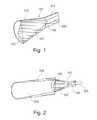
- FIG. 1shows a section view of a first module according to an exemplary embodiment of the invention.
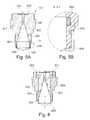
- FIG. 2shows a section view of a first module, of a second module and of a third module according to an exemplary embodiment of the invention.
- FIG. 3shows an enlarged view of a region of the arrangement according to FIG. 2 .
- FIG. 4shows a first module with a second module that is designed as a Cassegrain antenna.
- FIG. 5Ashows a section view of a first module according to a further exemplary embodiment of the invention.
- FIG. 5Bshows an enlarged section of the module of FIG. 5A .
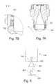
- FIG. 6shows a section view of a first module according to a further exemplary embodiment of the invention.
- FIG. 7Ashows a section view of a first module according to a further exemplary embodiment of the invention.
- FIG. 7Bshows an enlargement of a section of the module of FIG. 7A .
- FIG. 8shows a fill level radar according to an exemplary embodiment of the invention.
- FIG. 1shows a section view of a base antenna horn 101 .
- the base antenna horn 101comprises an antenna housing 113 , 114 .
- the region of the housing 114is conical in shape so that it forms an antenna funnel that is at least partly filled with a dielectric material 107 .
- the region 113is cylindrical in shape so that it forms a waveguide section 106 .
- a conically tapering tip 115 of the dielectric filling 107projects into the waveguide section 106 .
- a lens 105which also comprises dielectric material.
- the lens 105 , the antenna filling 107 and the conical tip 115may be formed in one piece.
- these three elements 105 , 107 and 115may be joined and may be made from different materials.
- the base horn 101is the central element, in other words the base, of the modular system. It is designed in such a way that all the other antenna types or antenna expansions, which will be specified in more detail below, can be fed with it.
- said base hornon its own already, in other words even without any expansion in whatever form, may be used for fill level measuring. This provides an advantage in that, on the one hand, measuring can also take place in very small container openings, and, on the other hand, various expansions can be affixed depending on the requirements, applications and the available space.
- the fill-level radar antenna constructed from the individual modulesis used in the W-band.
- the W-bandranges from 75 GHz to 110 GHz.
- the fill-level radar antennacan be used at a centre frequency of 79 GHz (bandwidth for example ⁇ 2 GHz or ⁇ 3 GHz).
- the base horn 101can, for example, comprise an external diameter of 19.05 cm (7.5′′), which then with a wall thickness of 0.5 mm of the antenna horn corresponds to an antenna aperture of approximately 18 mm.
- the frequency of 79 GHzis also in the so-called E-band, which ranges from 60 GHz to 90 GHz, because these “standard bands” overlap.
- the antenna horn 114would have an optimum length of approximately 110 mm.
- a dielectric materialfor example polytetrafluoroethylene (PTFE) or polypropylene (PP)
- a lens 105put in place, which lens 105 is made of the same material
- the horn lengthcan be reduced to approximately one quarter, i.e. 25 to 30 mm.
- the lenscan have any desired shape and can, in particular, also be made from some other dielectric material, as long as said lens operates as a convergent lens or a convex lens.
- the lensis spherical, aspherical or it is a fresnel lens.
- the lenscan be conical. In particular by affixing the lens in a corresponding shape, improved droplet draining behaviour vis-à-vis condensate residues is achieved.
- the base horn 101itself comprises a waveguide 106 , 113 that may be filled or not filled. If the waveguide is not filled, the dielectric filling 107 of the antenna horn 114 can leak into the waveguide 106 . This is shown by the tip 115 . In a conical horn, for example, the dielectric filling may reach right up to the imaginary tip of the cone that is formed by the conical horn. The tip in the waveguide may, of course, also assume an angle that differs from the opening angle of the antenna funnel 114 .
- the waveguide of the conical hornis designed as a round waveguide.
- the waveguidemay also assume some other form, e.g. oval or rectangular.
- the microwave signalsare coupled-in and/or coupled-out from the electronic- or high-frequency unit 805 (see FIG. 8 ).
- the waveguide 106can comprise a glass window 104 (see for example FIG. 5A ).
- This glass windowis used as a zone-separating element.
- the thickness of the glass windowis lambda-half or a multiple thereof, wherein lambda equals the wavelength of the transmission signal (relative to the centre frequency of the system).
- the value lambda-halfrelates to the permittivity value of the glass that is used for the window, i.e. half the wavelength of the transmission signal within the glass window.
- the glass windowcan be coated, on one side or on both sides, with a dielectric comprising a low permittivity value.
- a dielectriccomprising a low permittivity value.
- PTFEis a suitable material for this. Installation can, for example, take place by bonding to the glass.
- the thickness of this dielectricshould be lambda-quarter, wherein here again lambda equals the wavelength of the transmission signal relative to the centre frequency of the system.
- the value lambda-quarteralso relates to the permittivity value of the material used for coating, i.e. it is a quarter of the wavelength of the transmission signal within the coating used for the glass window.
- the glass windowmay have been installed at the top of the waveguide element 106 .
- Attachment of the glass window to the waveguide 106takes place, for example, by means of welding; but it may also be realized by means of a circumferential thread.
- the base horn 101may be used directly for measuring within the process. Furthermore, said base horn 101 may also be used for coupling-in with the use of other antennae. Below, various additional modular components are described which may be connected to the base antenna horn 101 .
- FIG. 2shows a section view of a base antenna horn 101 which on its front is connected to an expansion horn 102 , and which, on its rear is connected to a waveguide 103 .
- the base horn 101is used for coupling into the expansion horn 102 .
- the expansion horn 102can be designed so as to be shorter when compared to an arrangement where widening to the expansion horn 102 were to take place directly from the waveguide 103 (i.e. if the expansion horn were connected directly to the waveguide 103 ).
- the expansion horn 102is conical in the interior 108 .
- the interior 108 of the expansion horn 102can be “empty” or it can be partly or fully filled with a dielectric material.
- the waveguide 103is, for example, screwed to the waveguide section 106 of the base horn 101 so that it can easily be disconnected.
- the waveguide 106 of the base horn 101may also be directly connected to the electronics of the fill level radar.
- the following dimensionsmay be considered:
- FIG. 3shows an enlarged view of a partial section of the arrangement according to FIG. 2 .
- the transition 301 between the base horn 101 and the expansion horn 102is gapless, with the expansion horn 102 beginning directly at the end of the antenna filling or of the lens 105 .
- the diameter of the expansion hornis somewhat larger than the diameter of the filling of the base horn 101 .
- Attachment of the expansion horn 102 to the base horn 101takes place, for example, by way of a thread.
- the expansion hornis then simply screwed onto the base horn.
- connectionmay also be possible at this position.
- the two modulesmay be connected to a flange connection.
- the two modulesare, for example, connected with the use of four screws.
- a further optionwould be a plug-type connection that then clicks into place in some other manner.
- FIG. 4shows a further exemplary embodiment in which the base horn 101 is used for coupling into a parabolic Cassegrain antenna.
- the parabolic antenna 109comprises a conical reflector 110 , a parabolic mirror 111 and an antenna collar 112 .
- the arrows 401 , 402symbolize the transmission signal.
- the ratio between the focal length f and the diameter D (f/D ratio) of the parabolic mirroris, for example, 0.27 so that the sub-reflector 110 is situated within the mirror or within the mirror and its mirror edge 112 .
- Such an arrangementis, for example, shown in EP 1619747 A1.
- the sub-reflector 110is of hyperbolic shape.
- said sub-reflector 110can also assume other shapes, for example a conical shape.
- Attachment of the sub-reflectortakes place, for example, with two or more webs that are attached within the parabolic mirror or at the edge of the mirror. Such attachment can, for example, take place by means of welding.
- the transition from the horn antenna 101 to the parabolic mirror 109takes place, for example, in a gapless manner.
- the base horn 101can be used for coupling into a further filled antenna horn.
- the so-called expansion horn 102is also filled with one or several different dielectric materials.
- a lensis attached at the end of said expansion horn 102 .
- the lenscan have any desired shape, as long as it operates only as a convergent lens or a convex lens. For example it is spherical, aspherical or designed as a fresnel lens, or in a simplified manner it is simply conical in shape.
- the antenna systemcan be still further shortened.
- the lens formmay result in improved droplet draining behaviour vis-à-vis condensate residues.
- the base hornmay be used for coupling into a larger horn with a lens.
- the so-called expansion hornremains unfilled.
- a convergent lensmade of a dielectric material in order to shorten the antenna length. Possible lens shapes have been described above.
- the base hornmay be used for coupling into an upright-tube antenna or a rod antenna.
- FIG. 5Ashows a section view of a base antenna 101 according to an exemplary embodiment of the invention.
- the antenna housing 501is designed in a single piece.
- the filling 506 , 507 of the antenna, together with the lens 105has been pushed into the housing 501 from the front, with said filling 506 , 507 and lens 105 being installed in said housing 501 .
- the fillingis attached and held by a mounting ring 508 that has been screwed on from the front. This mounting ring 508 is shown in detail in FIG. 5B .
- the mounting ring 508is, for example, installed by means of a thread. Furthermore, the mounting ring 508 can be made from a flexible material. In this case it can be clicked to the housing 501 . Likewise, the mounting ring 508 can be bonded or welded to the housing.
- sealing rings 502 , 503 , 504are provided, which are inserted into corresponding ring-shaped recesses 505 of the housing.
- the dielectric filling of the antenna horncomprises two further regions 506 , 507 .
- the region 506is cylindrical, while the region 507 is conical with its tip projecting into the waveguide section 106 of the base antenna 101 .
- the cylindrical region 504can also be done without completely so that the filling is only conical. In this case the seals are also arranged only in the conical region.
- the glass window 104is shown, which is fitted into a corresponding recess in a carrier plate 509 .
- the carrier plate 509is in a corresponding recess in the housing 501 .
- the filling 506 , 507 with the lens 105may be designed in one piece or in two or three pieces.
- the mounting ring 508serves to press the individual parts together.
- FIGS. 6 and 7A , 7 Bshow two further exemplary embodiments of the base horn 101 , in which the antenna filling is installed and screwed into place from the rear (i.e. from the face that points towards the electronics).
- the antenna fillingis designed in one piece or in two pieces.
- FIG. 6 or 7 A, 7 Bshow various options of installing the O-rings 502 , 503 , 504 or 701 , 702 .
- two O-rings 502 , 503are arranged in the region of the conical section of the filling, whereas a third O-ring 504 is installed in the region of the cylindrical section of the filling (see FIG. 6 ).
- the O-rings 701 , 702can be arranged only in the cylindrical region of the filling (see FIGS. 7A , 7 B).
- recess for an O-ringinstead of being in the antenna horn, can also be partly or entirely in the filling.
- the term “recess”refers to a cut-in (groove) in which the O-ring is placed, as shown in FIG. 5B .
- the fillingis held by a circumferential projection 605 .
- the fillinghas been affixed by the ring 601 , 602 .
- an element 603is slid into the housing 604 , which element 603 forms the actual antenna horn.
- the housing in this embodimentcomprises multiple parts.
- the element 603comprises, for example, metal, preferably stainless steel or aluminium. It is also possible to use plastic, for example PBT (VALOX with glass fibre), which at least on the interior contour is metallized.
- the housing 604also comprises metal, for example stainless steel.
- FIG. 7Bshows an enlarged detail of section Y of FIG. 7A .
- the magnification scaleis 5:1.
- a further option of attaching the fillingconsists of injecting a thermoplastic material, for example perfluoroalkoxypolymer (PFA). This then acts like a hot-melt-type adhesive. In this embodiment the system is also sealed off at the same time.
- a thermoplastic materialfor example perfluoroalkoxypolymer (PFA).
- PFAperfluoroalkoxypolymer
- the systemmay be sealed off already without O-rings.
- FIG. 8shows a fill level radar 800 with a fill-level radar antenna 801 that comprises a first and second module as described above. Furthermore, a waveguide 103 is provided, which connects the antenna 801 to the electronics 805 .
- the antenna 801sends a transmission signal 802 in the direction of the product surface 804 , from which a corresponding return signal 803 is reflected and subsequently picked up by the antenna 801 .
Landscapes
- Physics & Mathematics (AREA)
- Electromagnetism (AREA)
- Thermal Sciences (AREA)
- Fluid Mechanics (AREA)
- General Physics & Mathematics (AREA)
- Aerials With Secondary Devices (AREA)
- Waveguide Aerials (AREA)
Abstract
Description
- An antenna horn with a diameter of 5.08 cm (2 inches) has an overall length of 425 mm including coupling into a waveguide with an interior diameter of 3.1 mm.
- An expansion horn (module2) with a diameter of 5.08 cm (2 inches) has an overall length of 270 mm including the base horn (module1) with a diameter of 19 mm (0.75 inch).
- This may result in shortening of the antenna to 64% of the original length.
- An antenna horn with a diameter of 2.54 cm (1 inch) has an overall length of 150 mm including coupling into a waveguide with an interior diameter of 3.1 mm.
- An expansion horn (module2) with a diameter of 2.54 cm (1 inch) has an overall length of 115 mm including the base horn (module1) with a diameter of 19 mm (0.75 inch).
- This may result in shortening to 77% of the original length.
Claims (15)
Priority Applications (1)
| Application Number | Priority Date | Filing Date | Title |
|---|---|---|---|
| US12/547,926US7940207B1 (en) | 2008-09-15 | 2009-08-26 | Modular design for a fill-level-radar antenna system |
Applications Claiming Priority (5)
| Application Number | Priority Date | Filing Date | Title |
|---|---|---|---|
| US9694708P | 2008-09-15 | 2008-09-15 | |
| EP08164367AEP2184807A1 (en) | 2008-09-15 | 2008-09-15 | Construction kit for a fill state radar antenna |
| EP08164367 | 2008-09-15 | ||
| EP08164367.8 | 2008-09-15 | ||
| US12/547,926US7940207B1 (en) | 2008-09-15 | 2009-08-26 | Modular design for a fill-level-radar antenna system |
Publications (3)
| Publication Number | Publication Date |
|---|---|
| US20100066594A1 US20100066594A1 (en) | 2010-03-18 |
| US7940207B1true US7940207B1 (en) | 2011-05-10 |
| US20110109499A9 US20110109499A9 (en) | 2011-05-12 |
Family
ID=40239567
Family Applications (1)
| Application Number | Title | Priority Date | Filing Date |
|---|---|---|---|
| US12/547,926ActiveUS7940207B1 (en) | 2008-09-15 | 2009-08-26 | Modular design for a fill-level-radar antenna system |
Country Status (3)
| Country | Link |
|---|---|
| US (1) | US7940207B1 (en) |
| EP (2) | EP2615690A3 (en) |
| CN (1) | CN101677147B (en) |
Cited By (159)
| Publication number | Priority date | Publication date | Assignee | Title |
|---|---|---|---|---|
| US20130220011A1 (en)* | 2012-02-23 | 2013-08-29 | Krohne Messtechnik Gmbh | Dielectric antenna and fill level sensor using the radar principle |
| US20130229299A1 (en)* | 2010-07-30 | 2013-09-05 | Toyota Jidosha Kabushiki Kaisha | Antenna cover |
| US20140009323A1 (en)* | 2012-07-04 | 2014-01-09 | Vega Grieshaber Kg | Waveguide coupling, high-frequency module, fill-level radar and use |
| US20150241261A1 (en)* | 2014-02-26 | 2015-08-27 | Finetek Co., Ltd. | Level measuring device with an integratable lens antenna |
| US20150330826A1 (en)* | 2013-01-03 | 2015-11-19 | Vega Grieshaber Kg | Parabolic antenna with an integrated sub reflector |
| US9544006B2 (en) | 2014-11-20 | 2017-01-10 | At&T Intellectual Property I, L.P. | Transmission device with mode division multiplexing and methods for use therewith |
| US9577306B2 (en) | 2014-10-21 | 2017-02-21 | At&T Intellectual Property I, L.P. | Guided-wave transmission device and methods for use therewith |
| US9596001B2 (en) | 2014-10-21 | 2017-03-14 | At&T Intellectual Property I, L.P. | Apparatus for providing communication services and methods thereof |
| US9608692B2 (en) | 2015-06-11 | 2017-03-28 | At&T Intellectual Property I, L.P. | Repeater and methods for use therewith |
| US9608740B2 (en) | 2015-07-15 | 2017-03-28 | At&T Intellectual Property I, L.P. | Method and apparatus for launching a wave mode that mitigates interference |
| US9615269B2 (en) | 2014-10-02 | 2017-04-04 | At&T Intellectual Property I, L.P. | Method and apparatus that provides fault tolerance in a communication network |
| US9628116B2 (en) | 2015-07-14 | 2017-04-18 | At&T Intellectual Property I, L.P. | Apparatus and methods for transmitting wireless signals |
| US9627768B2 (en) | 2014-10-21 | 2017-04-18 | At&T Intellectual Property I, L.P. | Guided-wave transmission device with non-fundamental mode propagation and methods for use therewith |
| US9640850B2 (en) | 2015-06-25 | 2017-05-02 | At&T Intellectual Property I, L.P. | Methods and apparatus for inducing a non-fundamental wave mode on a transmission medium |
| US9653770B2 (en) | 2014-10-21 | 2017-05-16 | At&T Intellectual Property I, L.P. | Guided wave coupler, coupling module and methods for use therewith |
| US9654173B2 (en) | 2014-11-20 | 2017-05-16 | At&T Intellectual Property I, L.P. | Apparatus for powering a communication device and methods thereof |
| US9661505B2 (en) | 2013-11-06 | 2017-05-23 | At&T Intellectual Property I, L.P. | Surface-wave communications and methods thereof |
| US9667317B2 (en) | 2015-06-15 | 2017-05-30 | At&T Intellectual Property I, L.P. | Method and apparatus for providing security using network traffic adjustments |
| US9685992B2 (en) | 2014-10-03 | 2017-06-20 | At&T Intellectual Property I, L.P. | Circuit panel network and methods thereof |
| US9692101B2 (en) | 2014-08-26 | 2017-06-27 | At&T Intellectual Property I, L.P. | Guided wave couplers for coupling electromagnetic waves between a waveguide surface and a surface of a wire |
| US9699785B2 (en) | 2012-12-05 | 2017-07-04 | At&T Intellectual Property I, L.P. | Backhaul link for distributed antenna system |
| US9705610B2 (en) | 2014-10-21 | 2017-07-11 | At&T Intellectual Property I, L.P. | Transmission device with impairment compensation and methods for use therewith |
| US9705561B2 (en) | 2015-04-24 | 2017-07-11 | At&T Intellectual Property I, L.P. | Directional coupling device and methods for use therewith |
| US9712350B2 (en) | 2014-11-20 | 2017-07-18 | At&T Intellectual Property I, L.P. | Transmission device with channel equalization and control and methods for use therewith |
| US9722318B2 (en) | 2015-07-14 | 2017-08-01 | At&T Intellectual Property I, L.P. | Method and apparatus for coupling an antenna to a device |
| US9729197B2 (en) | 2015-10-01 | 2017-08-08 | At&T Intellectual Property I, L.P. | Method and apparatus for communicating network management traffic over a network |
| US9735833B2 (en) | 2015-07-31 | 2017-08-15 | At&T Intellectual Property I, L.P. | Method and apparatus for communications management in a neighborhood network |
| US9742462B2 (en) | 2014-12-04 | 2017-08-22 | At&T Intellectual Property I, L.P. | Transmission medium and communication interfaces and methods for use therewith |
| US9749053B2 (en) | 2015-07-23 | 2017-08-29 | At&T Intellectual Property I, L.P. | Node device, repeater and methods for use therewith |
| US9748626B2 (en) | 2015-05-14 | 2017-08-29 | At&T Intellectual Property I, L.P. | Plurality of cables having different cross-sectional shapes which are bundled together to form a transmission medium |
| US9749013B2 (en) | 2015-03-17 | 2017-08-29 | At&T Intellectual Property I, L.P. | Method and apparatus for reducing attenuation of electromagnetic waves guided by a transmission medium |
| US9762289B2 (en) | 2014-10-14 | 2017-09-12 | At&T Intellectual Property I, L.P. | Method and apparatus for transmitting or receiving signals in a transportation system |
| US9769128B2 (en) | 2015-09-28 | 2017-09-19 | At&T Intellectual Property I, L.P. | Method and apparatus for encryption of communications over a network |
| US9768833B2 (en) | 2014-09-15 | 2017-09-19 | At&T Intellectual Property I, L.P. | Method and apparatus for sensing a condition in a transmission medium of electromagnetic waves |
| US9769020B2 (en) | 2014-10-21 | 2017-09-19 | At&T Intellectual Property I, L.P. | Method and apparatus for responding to events affecting communications in a communication network |
| US9780834B2 (en) | 2014-10-21 | 2017-10-03 | At&T Intellectual Property I, L.P. | Method and apparatus for transmitting electromagnetic waves |
| US9787412B2 (en) | 2015-06-25 | 2017-10-10 | At&T Intellectual Property I, L.P. | Methods and apparatus for inducing a fundamental wave mode on a transmission medium |
| US9793955B2 (en) | 2015-04-24 | 2017-10-17 | At&T Intellectual Property I, Lp | Passive electrical coupling device and methods for use therewith |
| US9793954B2 (en) | 2015-04-28 | 2017-10-17 | At&T Intellectual Property I, L.P. | Magnetic coupling device and methods for use therewith |
| US9794003B2 (en) | 2013-12-10 | 2017-10-17 | At&T Intellectual Property I, L.P. | Quasi-optical coupler |
| US9793951B2 (en) | 2015-07-15 | 2017-10-17 | At&T Intellectual Property I, L.P. | Method and apparatus for launching a wave mode that mitigates interference |
| US9800327B2 (en) | 2014-11-20 | 2017-10-24 | At&T Intellectual Property I, L.P. | Apparatus for controlling operations of a communication device and methods thereof |
| US9820146B2 (en) | 2015-06-12 | 2017-11-14 | At&T Intellectual Property I, L.P. | Method and apparatus for authentication and identity management of communicating devices |
| US9836957B2 (en) | 2015-07-14 | 2017-12-05 | At&T Intellectual Property I, L.P. | Method and apparatus for communicating with premises equipment |
| US9838896B1 (en) | 2016-12-09 | 2017-12-05 | At&T Intellectual Property I, L.P. | Method and apparatus for assessing network coverage |
| US9838078B2 (en) | 2015-07-31 | 2017-12-05 | At&T Intellectual Property I, L.P. | Method and apparatus for exchanging communication signals |
| US9847850B2 (en) | 2014-10-14 | 2017-12-19 | At&T Intellectual Property I, L.P. | Method and apparatus for adjusting a mode of communication in a communication network |
| US9847566B2 (en) | 2015-07-14 | 2017-12-19 | At&T Intellectual Property I, L.P. | Method and apparatus for adjusting a field of a signal to mitigate interference |
| US9853342B2 (en) | 2015-07-14 | 2017-12-26 | At&T Intellectual Property I, L.P. | Dielectric transmission medium connector and methods for use therewith |
| US9860075B1 (en) | 2016-08-26 | 2018-01-02 | At&T Intellectual Property I, L.P. | Method and communication node for broadband distribution |
| US9866276B2 (en) | 2014-10-10 | 2018-01-09 | At&T Intellectual Property I, L.P. | Method and apparatus for arranging communication sessions in a communication system |
| US9865911B2 (en) | 2015-06-25 | 2018-01-09 | At&T Intellectual Property I, L.P. | Waveguide system for slot radiating first electromagnetic waves that are combined into a non-fundamental wave mode second electromagnetic wave on a transmission medium |
| US9866309B2 (en) | 2015-06-03 | 2018-01-09 | At&T Intellectual Property I, Lp | Host node device and methods for use therewith |
| US9871282B2 (en) | 2015-05-14 | 2018-01-16 | At&T Intellectual Property I, L.P. | At least one transmission medium having a dielectric surface that is covered at least in part by a second dielectric |
| US9871283B2 (en) | 2015-07-23 | 2018-01-16 | At&T Intellectual Property I, Lp | Transmission medium having a dielectric core comprised of plural members connected by a ball and socket configuration |
| US9876570B2 (en) | 2015-02-20 | 2018-01-23 | At&T Intellectual Property I, Lp | Guided-wave transmission device with non-fundamental mode propagation and methods for use therewith |
| US9876264B2 (en) | 2015-10-02 | 2018-01-23 | At&T Intellectual Property I, Lp | Communication system, guided wave switch and methods for use therewith |
| US9876605B1 (en) | 2016-10-21 | 2018-01-23 | At&T Intellectual Property I, L.P. | Launcher and coupling system to support desired guided wave mode |
| US9882277B2 (en) | 2015-10-02 | 2018-01-30 | At&T Intellectual Property I, Lp | Communication device and antenna assembly with actuated gimbal mount |
| US9882257B2 (en) | 2015-07-14 | 2018-01-30 | At&T Intellectual Property I, L.P. | Method and apparatus for launching a wave mode that mitigates interference |
| US9887447B2 (en) | 2015-05-14 | 2018-02-06 | At&T Intellectual Property I, L.P. | Transmission medium having multiple cores and methods for use therewith |
| US9893795B1 (en) | 2016-12-07 | 2018-02-13 | At&T Intellectual Property I, Lp | Method and repeater for broadband distribution |
| US9904535B2 (en) | 2015-09-14 | 2018-02-27 | At&T Intellectual Property I, L.P. | Method and apparatus for distributing software |
| US9906269B2 (en) | 2014-09-17 | 2018-02-27 | At&T Intellectual Property I, L.P. | Monitoring and mitigating conditions in a communication network |
| US9912382B2 (en) | 2015-06-03 | 2018-03-06 | At&T Intellectual Property I, Lp | Network termination and methods for use therewith |
| US9912027B2 (en) | 2015-07-23 | 2018-03-06 | At&T Intellectual Property I, L.P. | Method and apparatus for exchanging communication signals |
| US9913139B2 (en) | 2015-06-09 | 2018-03-06 | At&T Intellectual Property I, L.P. | Signal fingerprinting for authentication of communicating devices |
| US9911020B1 (en) | 2016-12-08 | 2018-03-06 | At&T Intellectual Property I, L.P. | Method and apparatus for tracking via a radio frequency identification device |
| US9912419B1 (en) | 2016-08-24 | 2018-03-06 | At&T Intellectual Property I, L.P. | Method and apparatus for managing a fault in a distributed antenna system |
| US9917341B2 (en) | 2015-05-27 | 2018-03-13 | At&T Intellectual Property I, L.P. | Apparatus and method for launching electromagnetic waves and for modifying radial dimensions of the propagating electromagnetic waves |
| US9930668B2 (en) | 2013-05-31 | 2018-03-27 | At&T Intellectual Property I, L.P. | Remote distributed antenna system |
| US9927517B1 (en) | 2016-12-06 | 2018-03-27 | At&T Intellectual Property I, L.P. | Apparatus and methods for sensing rainfall |
| US9948333B2 (en) | 2015-07-23 | 2018-04-17 | At&T Intellectual Property I, L.P. | Method and apparatus for wireless communications to mitigate interference |
| US9948354B2 (en) | 2015-04-28 | 2018-04-17 | At&T Intellectual Property I, L.P. | Magnetic coupling device with reflective plate and methods for use therewith |
| US9954287B2 (en) | 2014-11-20 | 2018-04-24 | At&T Intellectual Property I, L.P. | Apparatus for converting wireless signals and electromagnetic waves and methods thereof |
| US9967173B2 (en) | 2015-07-31 | 2018-05-08 | At&T Intellectual Property I, L.P. | Method and apparatus for authentication and identity management of communicating devices |
| US9973940B1 (en) | 2017-02-27 | 2018-05-15 | At&T Intellectual Property I, L.P. | Apparatus and methods for dynamic impedance matching of a guided wave launcher |
| US9991580B2 (en) | 2016-10-21 | 2018-06-05 | At&T Intellectual Property I, L.P. | Launcher and coupling system for guided wave mode cancellation |
| US9999038B2 (en) | 2013-05-31 | 2018-06-12 | At&T Intellectual Property I, L.P. | Remote distributed antenna system |
| US9998870B1 (en) | 2016-12-08 | 2018-06-12 | At&T Intellectual Property I, L.P. | Method and apparatus for proximity sensing |
| US9997819B2 (en) | 2015-06-09 | 2018-06-12 | At&T Intellectual Property I, L.P. | Transmission medium and method for facilitating propagation of electromagnetic waves via a core |
| US10009901B2 (en) | 2015-09-16 | 2018-06-26 | At&T Intellectual Property I, L.P. | Method, apparatus, and computer-readable storage medium for managing utilization of wireless resources between base stations |
| US10009067B2 (en) | 2014-12-04 | 2018-06-26 | At&T Intellectual Property I, L.P. | Method and apparatus for configuring a communication interface |
| US10009065B2 (en) | 2012-12-05 | 2018-06-26 | At&T Intellectual Property I, L.P. | Backhaul link for distributed antenna system |
| US10009063B2 (en) | 2015-09-16 | 2018-06-26 | At&T Intellectual Property I, L.P. | Method and apparatus for use with a radio distributed antenna system having an out-of-band reference signal |
| US10020844B2 (en) | 2016-12-06 | 2018-07-10 | T&T Intellectual Property I, L.P. | Method and apparatus for broadcast communication via guided waves |
| US10020587B2 (en) | 2015-07-31 | 2018-07-10 | At&T Intellectual Property I, L.P. | Radial antenna and methods for use therewith |
| US10027397B2 (en) | 2016-12-07 | 2018-07-17 | At&T Intellectual Property I, L.P. | Distributed antenna system and methods for use therewith |
| US10033108B2 (en) | 2015-07-14 | 2018-07-24 | At&T Intellectual Property I, L.P. | Apparatus and methods for generating an electromagnetic wave having a wave mode that mitigates interference |
| US10033107B2 (en) | 2015-07-14 | 2018-07-24 | At&T Intellectual Property I, L.P. | Method and apparatus for coupling an antenna to a device |
| US10044409B2 (en) | 2015-07-14 | 2018-08-07 | At&T Intellectual Property I, L.P. | Transmission medium and methods for use therewith |
| US10069535B2 (en) | 2016-12-08 | 2018-09-04 | At&T Intellectual Property I, L.P. | Apparatus and methods for launching electromagnetic waves having a certain electric field structure |
| US10079661B2 (en) | 2015-09-16 | 2018-09-18 | At&T Intellectual Property I, L.P. | Method and apparatus for use with a radio distributed antenna system having a clock reference |
| US10090594B2 (en) | 2016-11-23 | 2018-10-02 | At&T Intellectual Property I, L.P. | Antenna system having structural configurations for assembly |
| US10090606B2 (en) | 2015-07-15 | 2018-10-02 | At&T Intellectual Property I, L.P. | Antenna system with dielectric array and methods for use therewith |
| US10103422B2 (en) | 2016-12-08 | 2018-10-16 | At&T Intellectual Property I, L.P. | Method and apparatus for mounting network devices |
| US10103801B2 (en) | 2015-06-03 | 2018-10-16 | At&T Intellectual Property I, L.P. | Host node device and methods for use therewith |
| US10135146B2 (en) | 2016-10-18 | 2018-11-20 | At&T Intellectual Property I, L.P. | Apparatus and methods for launching guided waves via circuits |
| US10135147B2 (en) | 2016-10-18 | 2018-11-20 | At&T Intellectual Property I, L.P. | Apparatus and methods for launching guided waves via an antenna |
| US10135145B2 (en) | 2016-12-06 | 2018-11-20 | At&T Intellectual Property I, L.P. | Apparatus and methods for generating an electromagnetic wave along a transmission medium |
| US10136434B2 (en) | 2015-09-16 | 2018-11-20 | At&T Intellectual Property I, L.P. | Method and apparatus for use with a radio distributed antenna system having an ultra-wideband control channel |
| US10142086B2 (en) | 2015-06-11 | 2018-11-27 | At&T Intellectual Property I, L.P. | Repeater and methods for use therewith |
| US10139820B2 (en) | 2016-12-07 | 2018-11-27 | At&T Intellectual Property I, L.P. | Method and apparatus for deploying equipment of a communication system |
| US10148016B2 (en) | 2015-07-14 | 2018-12-04 | At&T Intellectual Property I, L.P. | Apparatus and methods for communicating utilizing an antenna array |
| US10144036B2 (en) | 2015-01-30 | 2018-12-04 | At&T Intellectual Property I, L.P. | Method and apparatus for mitigating interference affecting a propagation of electromagnetic waves guided by a transmission medium |
| US10170840B2 (en) | 2015-07-14 | 2019-01-01 | At&T Intellectual Property I, L.P. | Apparatus and methods for sending or receiving electromagnetic signals |
| US10168695B2 (en) | 2016-12-07 | 2019-01-01 | At&T Intellectual Property I, L.P. | Method and apparatus for controlling an unmanned aircraft |
| US10178445B2 (en) | 2016-11-23 | 2019-01-08 | At&T Intellectual Property I, L.P. | Methods, devices, and systems for load balancing between a plurality of waveguides |
| US10205655B2 (en) | 2015-07-14 | 2019-02-12 | At&T Intellectual Property I, L.P. | Apparatus and methods for communicating utilizing an antenna array and multiple communication paths |
| US10224597B2 (en)* | 2013-07-03 | 2019-03-05 | Endress+Hauser SE+Co. KG | Antenna arrangement for a fill-level measuring device |
| US10224634B2 (en) | 2016-11-03 | 2019-03-05 | At&T Intellectual Property I, L.P. | Methods and apparatus for adjusting an operational characteristic of an antenna |
| US10225025B2 (en) | 2016-11-03 | 2019-03-05 | At&T Intellectual Property I, L.P. | Method and apparatus for detecting a fault in a communication system |
| US10243784B2 (en) | 2014-11-20 | 2019-03-26 | At&T Intellectual Property I, L.P. | System for generating topology information and methods thereof |
| US10243270B2 (en) | 2016-12-07 | 2019-03-26 | At&T Intellectual Property I, L.P. | Beam adaptive multi-feed dielectric antenna system and methods for use therewith |
| US10264586B2 (en) | 2016-12-09 | 2019-04-16 | At&T Mobility Ii Llc | Cloud-based packet controller and methods for use therewith |
| US10291334B2 (en) | 2016-11-03 | 2019-05-14 | At&T Intellectual Property I, L.P. | System for detecting a fault in a communication system |
| US10291311B2 (en) | 2016-09-09 | 2019-05-14 | At&T Intellectual Property I, L.P. | Method and apparatus for mitigating a fault in a distributed antenna system |
| US10298293B2 (en) | 2017-03-13 | 2019-05-21 | At&T Intellectual Property I, L.P. | Apparatus of communication utilizing wireless network devices |
| US10305190B2 (en) | 2016-12-01 | 2019-05-28 | At&T Intellectual Property I, L.P. | Reflecting dielectric antenna system and methods for use therewith |
| US10312567B2 (en) | 2016-10-26 | 2019-06-04 | At&T Intellectual Property I, L.P. | Launcher with planar strip antenna and methods for use therewith |
| US10320586B2 (en) | 2015-07-14 | 2019-06-11 | At&T Intellectual Property I, L.P. | Apparatus and methods for generating non-interfering electromagnetic waves on an insulated transmission medium |
| US10326494B2 (en) | 2016-12-06 | 2019-06-18 | At&T Intellectual Property I, L.P. | Apparatus for measurement de-embedding and methods for use therewith |
| US10326689B2 (en) | 2016-12-08 | 2019-06-18 | At&T Intellectual Property I, L.P. | Method and system for providing alternative communication paths |
| US10341142B2 (en) | 2015-07-14 | 2019-07-02 | At&T Intellectual Property I, L.P. | Apparatus and methods for generating non-interfering electromagnetic waves on an uninsulated conductor |
| US10340573B2 (en) | 2016-10-26 | 2019-07-02 | At&T Intellectual Property I, L.P. | Launcher with cylindrical coupling device and methods for use therewith |
| US10340600B2 (en) | 2016-10-18 | 2019-07-02 | At&T Intellectual Property I, L.P. | Apparatus and methods for launching guided waves via plural waveguide systems |
| US10340603B2 (en) | 2016-11-23 | 2019-07-02 | At&T Intellectual Property I, L.P. | Antenna system having shielded structural configurations for assembly |
| US10340601B2 (en) | 2016-11-23 | 2019-07-02 | At&T Intellectual Property I, L.P. | Multi-antenna system and methods for use therewith |
| US10340983B2 (en) | 2016-12-09 | 2019-07-02 | At&T Intellectual Property I, L.P. | Method and apparatus for surveying remote sites via guided wave communications |
| US10355367B2 (en) | 2015-10-16 | 2019-07-16 | At&T Intellectual Property I, L.P. | Antenna structure for exchanging wireless signals |
| US10361489B2 (en) | 2016-12-01 | 2019-07-23 | At&T Intellectual Property I, L.P. | Dielectric dish antenna system and methods for use therewith |
| US10359749B2 (en) | 2016-12-07 | 2019-07-23 | At&T Intellectual Property I, L.P. | Method and apparatus for utilities management via guided wave communication |
| US10374316B2 (en) | 2016-10-21 | 2019-08-06 | At&T Intellectual Property I, L.P. | System and dielectric antenna with non-uniform dielectric |
| US10382976B2 (en) | 2016-12-06 | 2019-08-13 | At&T Intellectual Property I, L.P. | Method and apparatus for managing wireless communications based on communication paths and network device positions |
| US10389029B2 (en) | 2016-12-07 | 2019-08-20 | At&T Intellectual Property I, L.P. | Multi-feed dielectric antenna system with core selection and methods for use therewith |
| US10389037B2 (en) | 2016-12-08 | 2019-08-20 | At&T Intellectual Property I, L.P. | Apparatus and methods for selecting sections of an antenna array and use therewith |
| US10411356B2 (en) | 2016-12-08 | 2019-09-10 | At&T Intellectual Property I, L.P. | Apparatus and methods for selectively targeting communication devices with an antenna array |
| US10439675B2 (en) | 2016-12-06 | 2019-10-08 | At&T Intellectual Property I, L.P. | Method and apparatus for repeating guided wave communication signals |
| US10446936B2 (en) | 2016-12-07 | 2019-10-15 | At&T Intellectual Property I, L.P. | Multi-feed dielectric antenna system and methods for use therewith |
| US10498044B2 (en) | 2016-11-03 | 2019-12-03 | At&T Intellectual Property I, L.P. | Apparatus for configuring a surface of an antenna |
| US10530505B2 (en) | 2016-12-08 | 2020-01-07 | At&T Intellectual Property I, L.P. | Apparatus and methods for launching electromagnetic waves along a transmission medium |
| US10535928B2 (en) | 2016-11-23 | 2020-01-14 | At&T Intellectual Property I, L.P. | Antenna system and methods for use therewith |
| US10547348B2 (en) | 2016-12-07 | 2020-01-28 | At&T Intellectual Property I, L.P. | Method and apparatus for switching transmission mediums in a communication system |
| US10601494B2 (en) | 2016-12-08 | 2020-03-24 | At&T Intellectual Property I, L.P. | Dual-band communication device and method for use therewith |
| US10637149B2 (en) | 2016-12-06 | 2020-04-28 | At&T Intellectual Property I, L.P. | Injection molded dielectric antenna and methods for use therewith |
| US10650940B2 (en) | 2015-05-15 | 2020-05-12 | At&T Intellectual Property I, L.P. | Transmission medium having a conductive material and methods for use therewith |
| US10665942B2 (en) | 2015-10-16 | 2020-05-26 | At&T Intellectual Property I, L.P. | Method and apparatus for adjusting wireless communications |
| US10694379B2 (en) | 2016-12-06 | 2020-06-23 | At&T Intellectual Property I, L.P. | Waveguide system with device-based authentication and methods for use therewith |
| US10727599B2 (en) | 2016-12-06 | 2020-07-28 | At&T Intellectual Property I, L.P. | Launcher with slot antenna and methods for use therewith |
| US10755542B2 (en) | 2016-12-06 | 2020-08-25 | At&T Intellectual Property I, L.P. | Method and apparatus for surveillance via guided wave communication |
| US10777873B2 (en) | 2016-12-08 | 2020-09-15 | At&T Intellectual Property I, L.P. | Method and apparatus for mounting network devices |
| US10784670B2 (en) | 2015-07-23 | 2020-09-22 | At&T Intellectual Property I, L.P. | Antenna support for aligning an antenna |
| US10797781B2 (en) | 2015-06-03 | 2020-10-06 | At&T Intellectual Property I, L.P. | Client node device and methods for use therewith |
| US10811767B2 (en) | 2016-10-21 | 2020-10-20 | At&T Intellectual Property I, L.P. | System and dielectric antenna with convex dielectric radome |
| US10819035B2 (en) | 2016-12-06 | 2020-10-27 | At&T Intellectual Property I, L.P. | Launcher with helical antenna and methods for use therewith |
| US10916969B2 (en) | 2016-12-08 | 2021-02-09 | At&T Intellectual Property I, L.P. | Method and apparatus for providing power using an inductive coupling |
| US10938108B2 (en) | 2016-12-08 | 2021-03-02 | At&T Intellectual Property I, L.P. | Frequency selective multi-feed dielectric antenna system and methods for use therewith |
| US20210123787A1 (en)* | 2019-10-23 | 2021-04-29 | Vega Grieshaber Kg | Radar measurement device and arrangement of a radar measurement device on a container |
| US11032819B2 (en) | 2016-09-15 | 2021-06-08 | At&T Intellectual Property I, L.P. | Method and apparatus for use with a radio distributed antenna system having a control channel reference signal |
Families Citing this family (19)
| Publication number | Priority date | Publication date | Assignee | Title |
|---|---|---|---|---|
| EP2469654B1 (en)* | 2010-12-21 | 2014-08-27 | Siemens Aktiengesellschaft | Horn antenna for a radar device |
| US8797207B2 (en)* | 2011-04-18 | 2014-08-05 | Vega Grieshaber Kg | Filling level measuring device antenna cover |
| CN104109540A (en)* | 2013-04-18 | 2014-10-22 | 宝山钢铁股份有限公司 | Microwave detection device of material level in dry quenching furnace |
| US9246227B2 (en)* | 2013-07-28 | 2016-01-26 | Finetek Co., Ltd. | Horn antenna device and step-shaped signal feed-in apparatus thereof |
| US9882285B2 (en)* | 2014-04-24 | 2018-01-30 | Honeywell International Inc. | Dielectric hollow antenna |
| DE102015111289B4 (en)* | 2015-07-13 | 2023-03-30 | Endress+Hauser SE+Co. KG | Antenna unit for a radar based level gauge and level gauge |
| US10129057B2 (en) | 2015-07-14 | 2018-11-13 | At&T Intellectual Property I, L.P. | Apparatus and methods for inducing electromagnetic waves on a cable |
| US10790593B2 (en) | 2015-07-14 | 2020-09-29 | At&T Intellectual Property I, L.P. | Method and apparatus including an antenna comprising a lens and a body coupled to a feedline having a structure that reduces reflections of electromagnetic waves |
| US10511346B2 (en) | 2015-07-14 | 2019-12-17 | At&T Intellectual Property I, L.P. | Apparatus and methods for inducing electromagnetic waves on an uninsulated conductor |
| US10439290B2 (en) | 2015-07-14 | 2019-10-08 | At&T Intellectual Property I, L.P. | Apparatus and methods for wireless communications |
| DE102015115395B4 (en)* | 2015-09-11 | 2017-06-14 | Krohne Messtechnik Gmbh | Antenna with a lens |
| EP3168579A1 (en)* | 2015-11-13 | 2017-05-17 | VEGA Grieshaber KG | Horn antenna |
| EP3168581B1 (en)* | 2015-11-13 | 2022-01-19 | VEGA Grieshaber KG | Horn antenna and radar fill level measuring device with a horn antenna |
| DE102016101756A1 (en)* | 2016-02-01 | 2017-08-03 | Vega Grieshaber Kg | Method for determining and displaying the optimum material thickness in level measurement with radar sensors |
| US11675070B2 (en)* | 2016-12-23 | 2023-06-13 | Iee International Electronics & Engineering S.A. | High-resolution 3D radar wave imaging device |
| DE102018211422A1 (en)* | 2018-07-10 | 2020-01-16 | Vega Grieshaber Kg | Level radar antenna arrangement for measuring a level in a container |
| CN109708723B (en)* | 2018-11-21 | 2020-11-10 | 北京古大仪表有限公司 | Radar level meter |
| DE102020202214A1 (en) | 2020-02-20 | 2021-08-26 | Vega Grieshaber Kg | Construction kit for a radar sensor |
| CN112787075A (en)* | 2021-02-09 | 2021-05-11 | 北京锐达仪表有限公司 | High-frequency radar level meter |
Citations (11)
| Publication number | Priority date | Publication date | Assignee | Title |
|---|---|---|---|---|
| US2408055A (en)* | 1944-07-17 | 1946-09-24 | Gen Electric | Ultra high frequency coupling device and system |
| EP0859427A1 (en) | 1997-02-14 | 1998-08-19 | Andrew A.G. | Dual-reflector microwave antenna |
| EP0871241A2 (en) | 1997-04-09 | 1998-10-14 | Nec Corporation | Lens antenna |
| EP0922942A1 (en) | 1997-12-10 | 1999-06-16 | Endress + Hauser GmbH + Co. | Microwave level gauge with a dielectric insert and method for the manufacture of the dielectric |
| US6393909B1 (en)* | 1998-03-18 | 2002-05-28 | Vega Grieshaber Xg | Fluid level measuring device measuring fluid level in a container at high temperatures and/or high pressures and/or in a chemically aggressive environment using microwaves |
| US20020163401A1 (en)* | 2001-05-01 | 2002-11-07 | Zhang Henry Z. | Wideband coaxial orthogonal-mode junction coupler |
| US20020176139A1 (en)* | 2001-05-02 | 2002-11-28 | Louis Slaughter | SONET capable millimeter wave communication system |
| WO2003078936A1 (en) | 2002-03-18 | 2003-09-25 | Saab Marine Electronics Ab | Horn antenna |
| US20030231679A1 (en)* | 2002-06-10 | 2003-12-18 | Hitoshi Umemoto | Semiconductor laser device |
| EP1619747A1 (en) | 2004-07-20 | 2006-01-25 | VEGA Grieshaber KG | Level gauge parabolic antenna and filling level gauge having a parabolic antenna |
| WO2006120124A1 (en)* | 2005-05-11 | 2006-11-16 | Endress+Hauser Gmbh+Co.Kg | Device for determining and monitoring the level of a medium in a container |
Family Cites Families (2)
| Publication number | Priority date | Publication date | Assignee | Title |
|---|---|---|---|---|
| CN1592845B (en)* | 2001-11-26 | 2010-05-05 | Vega格里沙贝两合公司 | Antenna system for a level measuring device |
| US7204140B2 (en)* | 2004-07-01 | 2007-04-17 | Saab Rosemount Tank Radar Ab | Radar level gauge flange |
- 2008
- 2008-09-15EPEP13162778.8Apatent/EP2615690A3/ennot_activeWithdrawn
- 2008-09-15EPEP08164367Apatent/EP2184807A1/ennot_activeWithdrawn
- 2009
- 2009-08-26USUS12/547,926patent/US7940207B1/enactiveActive
- 2009-09-11CNCN200910170791.1Apatent/CN101677147B/ennot_activeExpired - Fee Related
Patent Citations (15)
| Publication number | Priority date | Publication date | Assignee | Title |
|---|---|---|---|---|
| US2408055A (en)* | 1944-07-17 | 1946-09-24 | Gen Electric | Ultra high frequency coupling device and system |
| EP0859427A1 (en) | 1997-02-14 | 1998-08-19 | Andrew A.G. | Dual-reflector microwave antenna |
| EP0871241A2 (en) | 1997-04-09 | 1998-10-14 | Nec Corporation | Lens antenna |
| EP0922942A1 (en) | 1997-12-10 | 1999-06-16 | Endress + Hauser GmbH + Co. | Microwave level gauge with a dielectric insert and method for the manufacture of the dielectric |
| US6417748B1 (en)* | 1997-12-10 | 2002-07-09 | Endress + Hauser Gmbh + Co. | Filling level measuring device operating with microwaves, having an insert composed of a dielectric, and process for producing the dielectric |
| US6393909B1 (en)* | 1998-03-18 | 2002-05-28 | Vega Grieshaber Xg | Fluid level measuring device measuring fluid level in a container at high temperatures and/or high pressures and/or in a chemically aggressive environment using microwaves |
| US20020163401A1 (en)* | 2001-05-01 | 2002-11-07 | Zhang Henry Z. | Wideband coaxial orthogonal-mode junction coupler |
| US20020176139A1 (en)* | 2001-05-02 | 2002-11-28 | Louis Slaughter | SONET capable millimeter wave communication system |
| WO2003078936A1 (en) | 2002-03-18 | 2003-09-25 | Saab Marine Electronics Ab | Horn antenna |
| US20030179148A1 (en)* | 2002-03-18 | 2003-09-25 | Magnus Ohlsson | Horn antenna |
| US20030231679A1 (en)* | 2002-06-10 | 2003-12-18 | Hitoshi Umemoto | Semiconductor laser device |
| EP1619747A1 (en) | 2004-07-20 | 2006-01-25 | VEGA Grieshaber KG | Level gauge parabolic antenna and filling level gauge having a parabolic antenna |
| US20060017640A1 (en) | 2004-07-20 | 2006-01-26 | Klaus Kienzle | Parabolic antenna of a level measuring instrument and level measuring instrument with a parabolic antenna |
| WO2006120124A1 (en)* | 2005-05-11 | 2006-11-16 | Endress+Hauser Gmbh+Co.Kg | Device for determining and monitoring the level of a medium in a container |
| US20090212996A1 (en)* | 2005-05-11 | 2009-08-27 | Endress + Hauser Gmbh + Co., Kg | Device for determining and monitoring the level of a medium in a container |
Cited By (203)
| Publication number | Priority date | Publication date | Assignee | Title |
|---|---|---|---|---|
| US20130229299A1 (en)* | 2010-07-30 | 2013-09-05 | Toyota Jidosha Kabushiki Kaisha | Antenna cover |
| US9110162B2 (en)* | 2010-07-30 | 2015-08-18 | Toyota Jidosha Kabushiki Kaisha | Antenna cover |
| US8881588B2 (en)* | 2012-02-23 | 2014-11-11 | Krohne Messtechnik Gmbh | Dielectric antenna and fill level sensor using the radar principle |
| US20130220011A1 (en)* | 2012-02-23 | 2013-08-29 | Krohne Messtechnik Gmbh | Dielectric antenna and fill level sensor using the radar principle |
| US20140009323A1 (en)* | 2012-07-04 | 2014-01-09 | Vega Grieshaber Kg | Waveguide coupling, high-frequency module, fill-level radar and use |
| US9212942B2 (en)* | 2012-07-04 | 2015-12-15 | Vega Grieshaber Kg | Waveguide coupling, high-frequency module, fill-level radar and use |
| US10009065B2 (en) | 2012-12-05 | 2018-06-26 | At&T Intellectual Property I, L.P. | Backhaul link for distributed antenna system |
| US10194437B2 (en) | 2012-12-05 | 2019-01-29 | At&T Intellectual Property I, L.P. | Backhaul link for distributed antenna system |
| US9788326B2 (en) | 2012-12-05 | 2017-10-10 | At&T Intellectual Property I, L.P. | Backhaul link for distributed antenna system |
| US9699785B2 (en) | 2012-12-05 | 2017-07-04 | At&T Intellectual Property I, L.P. | Backhaul link for distributed antenna system |
| US9417111B2 (en)* | 2013-01-03 | 2016-08-16 | Vega Grieshaber Kg | Parabolic antenna with an integrated sub reflector |
| US20150330826A1 (en)* | 2013-01-03 | 2015-11-19 | Vega Grieshaber Kg | Parabolic antenna with an integrated sub reflector |
| US10091787B2 (en) | 2013-05-31 | 2018-10-02 | At&T Intellectual Property I, L.P. | Remote distributed antenna system |
| US9999038B2 (en) | 2013-05-31 | 2018-06-12 | At&T Intellectual Property I, L.P. | Remote distributed antenna system |
| US9930668B2 (en) | 2013-05-31 | 2018-03-27 | At&T Intellectual Property I, L.P. | Remote distributed antenna system |
| US10051630B2 (en) | 2013-05-31 | 2018-08-14 | At&T Intellectual Property I, L.P. | Remote distributed antenna system |
| US10224597B2 (en)* | 2013-07-03 | 2019-03-05 | Endress+Hauser SE+Co. KG | Antenna arrangement for a fill-level measuring device |
| US9674711B2 (en) | 2013-11-06 | 2017-06-06 | At&T Intellectual Property I, L.P. | Surface-wave communications and methods thereof |
| US9661505B2 (en) | 2013-11-06 | 2017-05-23 | At&T Intellectual Property I, L.P. | Surface-wave communications and methods thereof |
| US9794003B2 (en) | 2013-12-10 | 2017-10-17 | At&T Intellectual Property I, L.P. | Quasi-optical coupler |
| US9876584B2 (en) | 2013-12-10 | 2018-01-23 | At&T Intellectual Property I, L.P. | Quasi-optical coupler |
| US20150241261A1 (en)* | 2014-02-26 | 2015-08-27 | Finetek Co., Ltd. | Level measuring device with an integratable lens antenna |
| US9404787B2 (en)* | 2014-02-26 | 2016-08-02 | Finetek Co., Ltd. | Level measuring device with an integratable lens antenna |
| US10096881B2 (en) | 2014-08-26 | 2018-10-09 | At&T Intellectual Property I, L.P. | Guided wave couplers for coupling electromagnetic waves to an outer surface of a transmission medium |
| US9692101B2 (en) | 2014-08-26 | 2017-06-27 | At&T Intellectual Property I, L.P. | Guided wave couplers for coupling electromagnetic waves between a waveguide surface and a surface of a wire |
| US9768833B2 (en) | 2014-09-15 | 2017-09-19 | At&T Intellectual Property I, L.P. | Method and apparatus for sensing a condition in a transmission medium of electromagnetic waves |
| US9906269B2 (en) | 2014-09-17 | 2018-02-27 | At&T Intellectual Property I, L.P. | Monitoring and mitigating conditions in a communication network |
| US10063280B2 (en) | 2014-09-17 | 2018-08-28 | At&T Intellectual Property I, L.P. | Monitoring and mitigating conditions in a communication network |
| US9615269B2 (en) | 2014-10-02 | 2017-04-04 | At&T Intellectual Property I, L.P. | Method and apparatus that provides fault tolerance in a communication network |
| US9973416B2 (en) | 2014-10-02 | 2018-05-15 | At&T Intellectual Property I, L.P. | Method and apparatus that provides fault tolerance in a communication network |
| US9998932B2 (en) | 2014-10-02 | 2018-06-12 | At&T Intellectual Property I, L.P. | Method and apparatus that provides fault tolerance in a communication network |
| US9685992B2 (en) | 2014-10-03 | 2017-06-20 | At&T Intellectual Property I, L.P. | Circuit panel network and methods thereof |
| US9866276B2 (en) | 2014-10-10 | 2018-01-09 | At&T Intellectual Property I, L.P. | Method and apparatus for arranging communication sessions in a communication system |
| US9762289B2 (en) | 2014-10-14 | 2017-09-12 | At&T Intellectual Property I, L.P. | Method and apparatus for transmitting or receiving signals in a transportation system |
| US9973299B2 (en) | 2014-10-14 | 2018-05-15 | At&T Intellectual Property I, L.P. | Method and apparatus for adjusting a mode of communication in a communication network |
| US9847850B2 (en) | 2014-10-14 | 2017-12-19 | At&T Intellectual Property I, L.P. | Method and apparatus for adjusting a mode of communication in a communication network |
| US9596001B2 (en) | 2014-10-21 | 2017-03-14 | At&T Intellectual Property I, L.P. | Apparatus for providing communication services and methods thereof |
| US9876587B2 (en) | 2014-10-21 | 2018-01-23 | At&T Intellectual Property I, L.P. | Transmission device with impairment compensation and methods for use therewith |
| US9912033B2 (en) | 2014-10-21 | 2018-03-06 | At&T Intellectual Property I, Lp | Guided wave coupler, coupling module and methods for use therewith |
| US9948355B2 (en) | 2014-10-21 | 2018-04-17 | At&T Intellectual Property I, L.P. | Apparatus for providing communication services and methods thereof |
| US9871558B2 (en) | 2014-10-21 | 2018-01-16 | At&T Intellectual Property I, L.P. | Guided-wave transmission device and methods for use therewith |
| US9954286B2 (en) | 2014-10-21 | 2018-04-24 | At&T Intellectual Property I, L.P. | Guided-wave transmission device with non-fundamental mode propagation and methods for use therewith |
| US9769020B2 (en) | 2014-10-21 | 2017-09-19 | At&T Intellectual Property I, L.P. | Method and apparatus for responding to events affecting communications in a communication network |
| US9780834B2 (en) | 2014-10-21 | 2017-10-03 | At&T Intellectual Property I, L.P. | Method and apparatus for transmitting electromagnetic waves |
| US9705610B2 (en) | 2014-10-21 | 2017-07-11 | At&T Intellectual Property I, L.P. | Transmission device with impairment compensation and methods for use therewith |
| US9960808B2 (en) | 2014-10-21 | 2018-05-01 | At&T Intellectual Property I, L.P. | Guided-wave transmission device and methods for use therewith |
| US9653770B2 (en) | 2014-10-21 | 2017-05-16 | At&T Intellectual Property I, L.P. | Guided wave coupler, coupling module and methods for use therewith |
| US9627768B2 (en) | 2014-10-21 | 2017-04-18 | At&T Intellectual Property I, L.P. | Guided-wave transmission device with non-fundamental mode propagation and methods for use therewith |
| US9577306B2 (en) | 2014-10-21 | 2017-02-21 | At&T Intellectual Property I, L.P. | Guided-wave transmission device and methods for use therewith |
| US9712350B2 (en) | 2014-11-20 | 2017-07-18 | At&T Intellectual Property I, L.P. | Transmission device with channel equalization and control and methods for use therewith |
| US9654173B2 (en) | 2014-11-20 | 2017-05-16 | At&T Intellectual Property I, L.P. | Apparatus for powering a communication device and methods thereof |
| US10243784B2 (en) | 2014-11-20 | 2019-03-26 | At&T Intellectual Property I, L.P. | System for generating topology information and methods thereof |
| US9544006B2 (en) | 2014-11-20 | 2017-01-10 | At&T Intellectual Property I, L.P. | Transmission device with mode division multiplexing and methods for use therewith |
| US9749083B2 (en) | 2014-11-20 | 2017-08-29 | At&T Intellectual Property I, L.P. | Transmission device with mode division multiplexing and methods for use therewith |
| US9800327B2 (en) | 2014-11-20 | 2017-10-24 | At&T Intellectual Property I, L.P. | Apparatus for controlling operations of a communication device and methods thereof |
| US9742521B2 (en) | 2014-11-20 | 2017-08-22 | At&T Intellectual Property I, L.P. | Transmission device with mode division multiplexing and methods for use therewith |
| US9954287B2 (en) | 2014-11-20 | 2018-04-24 | At&T Intellectual Property I, L.P. | Apparatus for converting wireless signals and electromagnetic waves and methods thereof |
| US10009067B2 (en) | 2014-12-04 | 2018-06-26 | At&T Intellectual Property I, L.P. | Method and apparatus for configuring a communication interface |
| US9742462B2 (en) | 2014-12-04 | 2017-08-22 | At&T Intellectual Property I, L.P. | Transmission medium and communication interfaces and methods for use therewith |
| US10144036B2 (en) | 2015-01-30 | 2018-12-04 | At&T Intellectual Property I, L.P. | Method and apparatus for mitigating interference affecting a propagation of electromagnetic waves guided by a transmission medium |
| US9876570B2 (en) | 2015-02-20 | 2018-01-23 | At&T Intellectual Property I, Lp | Guided-wave transmission device with non-fundamental mode propagation and methods for use therewith |
| US9876571B2 (en) | 2015-02-20 | 2018-01-23 | At&T Intellectual Property I, Lp | Guided-wave transmission device with non-fundamental mode propagation and methods for use therewith |
| US9749013B2 (en) | 2015-03-17 | 2017-08-29 | At&T Intellectual Property I, L.P. | Method and apparatus for reducing attenuation of electromagnetic waves guided by a transmission medium |
| US9793955B2 (en) | 2015-04-24 | 2017-10-17 | At&T Intellectual Property I, Lp | Passive electrical coupling device and methods for use therewith |
| US9705561B2 (en) | 2015-04-24 | 2017-07-11 | At&T Intellectual Property I, L.P. | Directional coupling device and methods for use therewith |
| US10224981B2 (en) | 2015-04-24 | 2019-03-05 | At&T Intellectual Property I, Lp | Passive electrical coupling device and methods for use therewith |
| US9831912B2 (en) | 2015-04-24 | 2017-11-28 | At&T Intellectual Property I, Lp | Directional coupling device and methods for use therewith |
| US9948354B2 (en) | 2015-04-28 | 2018-04-17 | At&T Intellectual Property I, L.P. | Magnetic coupling device with reflective plate and methods for use therewith |
| US9793954B2 (en) | 2015-04-28 | 2017-10-17 | At&T Intellectual Property I, L.P. | Magnetic coupling device and methods for use therewith |
| US9871282B2 (en) | 2015-05-14 | 2018-01-16 | At&T Intellectual Property I, L.P. | At least one transmission medium having a dielectric surface that is covered at least in part by a second dielectric |
| US9887447B2 (en) | 2015-05-14 | 2018-02-06 | At&T Intellectual Property I, L.P. | Transmission medium having multiple cores and methods for use therewith |
| US9748626B2 (en) | 2015-05-14 | 2017-08-29 | At&T Intellectual Property I, L.P. | Plurality of cables having different cross-sectional shapes which are bundled together to form a transmission medium |
| US10650940B2 (en) | 2015-05-15 | 2020-05-12 | At&T Intellectual Property I, L.P. | Transmission medium having a conductive material and methods for use therewith |
| US9917341B2 (en) | 2015-05-27 | 2018-03-13 | At&T Intellectual Property I, L.P. | Apparatus and method for launching electromagnetic waves and for modifying radial dimensions of the propagating electromagnetic waves |
| US9866309B2 (en) | 2015-06-03 | 2018-01-09 | At&T Intellectual Property I, Lp | Host node device and methods for use therewith |
| US10812174B2 (en) | 2015-06-03 | 2020-10-20 | At&T Intellectual Property I, L.P. | Client node device and methods for use therewith |
| US10797781B2 (en) | 2015-06-03 | 2020-10-06 | At&T Intellectual Property I, L.P. | Client node device and methods for use therewith |
| US9967002B2 (en) | 2015-06-03 | 2018-05-08 | At&T Intellectual I, Lp | Network termination and methods for use therewith |
| US9912381B2 (en) | 2015-06-03 | 2018-03-06 | At&T Intellectual Property I, Lp | Network termination and methods for use therewith |
| US10050697B2 (en) | 2015-06-03 | 2018-08-14 | At&T Intellectual Property I, L.P. | Host node device and methods for use therewith |
| US9935703B2 (en) | 2015-06-03 | 2018-04-03 | At&T Intellectual Property I, L.P. | Host node device and methods for use therewith |
| US9912382B2 (en) | 2015-06-03 | 2018-03-06 | At&T Intellectual Property I, Lp | Network termination and methods for use therewith |
| US10103801B2 (en) | 2015-06-03 | 2018-10-16 | At&T Intellectual Property I, L.P. | Host node device and methods for use therewith |
| US9913139B2 (en) | 2015-06-09 | 2018-03-06 | At&T Intellectual Property I, L.P. | Signal fingerprinting for authentication of communicating devices |
| US9997819B2 (en) | 2015-06-09 | 2018-06-12 | At&T Intellectual Property I, L.P. | Transmission medium and method for facilitating propagation of electromagnetic waves via a core |
| US10142086B2 (en) | 2015-06-11 | 2018-11-27 | At&T Intellectual Property I, L.P. | Repeater and methods for use therewith |
| US10142010B2 (en) | 2015-06-11 | 2018-11-27 | At&T Intellectual Property I, L.P. | Repeater and methods for use therewith |
| US9608692B2 (en) | 2015-06-11 | 2017-03-28 | At&T Intellectual Property I, L.P. | Repeater and methods for use therewith |
| US10027398B2 (en) | 2015-06-11 | 2018-07-17 | At&T Intellectual Property I, Lp | Repeater and methods for use therewith |
| US9820146B2 (en) | 2015-06-12 | 2017-11-14 | At&T Intellectual Property I, L.P. | Method and apparatus for authentication and identity management of communicating devices |
| US9667317B2 (en) | 2015-06-15 | 2017-05-30 | At&T Intellectual Property I, L.P. | Method and apparatus for providing security using network traffic adjustments |
| US10069185B2 (en) | 2015-06-25 | 2018-09-04 | At&T Intellectual Property I, L.P. | Methods and apparatus for inducing a non-fundamental wave mode on a transmission medium |
| US9865911B2 (en) | 2015-06-25 | 2018-01-09 | At&T Intellectual Property I, L.P. | Waveguide system for slot radiating first electromagnetic waves that are combined into a non-fundamental wave mode second electromagnetic wave on a transmission medium |
| US9882657B2 (en) | 2015-06-25 | 2018-01-30 | At&T Intellectual Property I, L.P. | Methods and apparatus for inducing a fundamental wave mode on a transmission medium |
| US9640850B2 (en) | 2015-06-25 | 2017-05-02 | At&T Intellectual Property I, L.P. | Methods and apparatus for inducing a non-fundamental wave mode on a transmission medium |
| US9787412B2 (en) | 2015-06-25 | 2017-10-10 | At&T Intellectual Property I, L.P. | Methods and apparatus for inducing a fundamental wave mode on a transmission medium |
| US9628116B2 (en) | 2015-07-14 | 2017-04-18 | At&T Intellectual Property I, L.P. | Apparatus and methods for transmitting wireless signals |
| US10341142B2 (en) | 2015-07-14 | 2019-07-02 | At&T Intellectual Property I, L.P. | Apparatus and methods for generating non-interfering electromagnetic waves on an uninsulated conductor |
| US9929755B2 (en) | 2015-07-14 | 2018-03-27 | At&T Intellectual Property I, L.P. | Method and apparatus for coupling an antenna to a device |
| US10205655B2 (en) | 2015-07-14 | 2019-02-12 | At&T Intellectual Property I, L.P. | Apparatus and methods for communicating utilizing an antenna array and multiple communication paths |
| US9847566B2 (en) | 2015-07-14 | 2017-12-19 | At&T Intellectual Property I, L.P. | Method and apparatus for adjusting a field of a signal to mitigate interference |
| US10170840B2 (en) | 2015-07-14 | 2019-01-01 | At&T Intellectual Property I, L.P. | Apparatus and methods for sending or receiving electromagnetic signals |
| US9947982B2 (en) | 2015-07-14 | 2018-04-17 | At&T Intellectual Property I, Lp | Dielectric transmission medium connector and methods for use therewith |
| US9853342B2 (en) | 2015-07-14 | 2017-12-26 | At&T Intellectual Property I, L.P. | Dielectric transmission medium connector and methods for use therewith |
| US10044409B2 (en) | 2015-07-14 | 2018-08-07 | At&T Intellectual Property I, L.P. | Transmission medium and methods for use therewith |
| US9882257B2 (en) | 2015-07-14 | 2018-01-30 | At&T Intellectual Property I, L.P. | Method and apparatus for launching a wave mode that mitigates interference |
| US10148016B2 (en) | 2015-07-14 | 2018-12-04 | At&T Intellectual Property I, L.P. | Apparatus and methods for communicating utilizing an antenna array |
| US10033107B2 (en) | 2015-07-14 | 2018-07-24 | At&T Intellectual Property I, L.P. | Method and apparatus for coupling an antenna to a device |
| US9722318B2 (en) | 2015-07-14 | 2017-08-01 | At&T Intellectual Property I, L.P. | Method and apparatus for coupling an antenna to a device |
| US10033108B2 (en) | 2015-07-14 | 2018-07-24 | At&T Intellectual Property I, L.P. | Apparatus and methods for generating an electromagnetic wave having a wave mode that mitigates interference |
| US9836957B2 (en) | 2015-07-14 | 2017-12-05 | At&T Intellectual Property I, L.P. | Method and apparatus for communicating with premises equipment |
| US10320586B2 (en) | 2015-07-14 | 2019-06-11 | At&T Intellectual Property I, L.P. | Apparatus and methods for generating non-interfering electromagnetic waves on an insulated transmission medium |
| US9793951B2 (en) | 2015-07-15 | 2017-10-17 | At&T Intellectual Property I, L.P. | Method and apparatus for launching a wave mode that mitigates interference |
| US10090606B2 (en) | 2015-07-15 | 2018-10-02 | At&T Intellectual Property I, L.P. | Antenna system with dielectric array and methods for use therewith |
| US9608740B2 (en) | 2015-07-15 | 2017-03-28 | At&T Intellectual Property I, L.P. | Method and apparatus for launching a wave mode that mitigates interference |
| US9948333B2 (en) | 2015-07-23 | 2018-04-17 | At&T Intellectual Property I, L.P. | Method and apparatus for wireless communications to mitigate interference |
| US10784670B2 (en) | 2015-07-23 | 2020-09-22 | At&T Intellectual Property I, L.P. | Antenna support for aligning an antenna |
| US9806818B2 (en) | 2015-07-23 | 2017-10-31 | At&T Intellectual Property I, Lp | Node device, repeater and methods for use therewith |
| US9871283B2 (en) | 2015-07-23 | 2018-01-16 | At&T Intellectual Property I, Lp | Transmission medium having a dielectric core comprised of plural members connected by a ball and socket configuration |
| US10074886B2 (en) | 2015-07-23 | 2018-09-11 | At&T Intellectual Property I, L.P. | Dielectric transmission medium comprising a plurality of rigid dielectric members coupled together in a ball and socket configuration |
| US9749053B2 (en) | 2015-07-23 | 2017-08-29 | At&T Intellectual Property I, L.P. | Node device, repeater and methods for use therewith |
| US9912027B2 (en) | 2015-07-23 | 2018-03-06 | At&T Intellectual Property I, L.P. | Method and apparatus for exchanging communication signals |
| US9838078B2 (en) | 2015-07-31 | 2017-12-05 | At&T Intellectual Property I, L.P. | Method and apparatus for exchanging communication signals |
| US9735833B2 (en) | 2015-07-31 | 2017-08-15 | At&T Intellectual Property I, L.P. | Method and apparatus for communications management in a neighborhood network |
| US9967173B2 (en) | 2015-07-31 | 2018-05-08 | At&T Intellectual Property I, L.P. | Method and apparatus for authentication and identity management of communicating devices |
| US10020587B2 (en) | 2015-07-31 | 2018-07-10 | At&T Intellectual Property I, L.P. | Radial antenna and methods for use therewith |
| US9904535B2 (en) | 2015-09-14 | 2018-02-27 | At&T Intellectual Property I, L.P. | Method and apparatus for distributing software |
| US10136434B2 (en) | 2015-09-16 | 2018-11-20 | At&T Intellectual Property I, L.P. | Method and apparatus for use with a radio distributed antenna system having an ultra-wideband control channel |
| US10009901B2 (en) | 2015-09-16 | 2018-06-26 | At&T Intellectual Property I, L.P. | Method, apparatus, and computer-readable storage medium for managing utilization of wireless resources between base stations |
| US10079661B2 (en) | 2015-09-16 | 2018-09-18 | At&T Intellectual Property I, L.P. | Method and apparatus for use with a radio distributed antenna system having a clock reference |
| US10225842B2 (en) | 2015-09-16 | 2019-03-05 | At&T Intellectual Property I, L.P. | Method, device and storage medium for communications using a modulated signal and a reference signal |
| US10009063B2 (en) | 2015-09-16 | 2018-06-26 | At&T Intellectual Property I, L.P. | Method and apparatus for use with a radio distributed antenna system having an out-of-band reference signal |
| US10349418B2 (en) | 2015-09-16 | 2019-07-09 | At&T Intellectual Property I, L.P. | Method and apparatus for managing utilization of wireless resources via use of a reference signal to reduce distortion |
| US9769128B2 (en) | 2015-09-28 | 2017-09-19 | At&T Intellectual Property I, L.P. | Method and apparatus for encryption of communications over a network |
| US9729197B2 (en) | 2015-10-01 | 2017-08-08 | At&T Intellectual Property I, L.P. | Method and apparatus for communicating network management traffic over a network |
| US9882277B2 (en) | 2015-10-02 | 2018-01-30 | At&T Intellectual Property I, Lp | Communication device and antenna assembly with actuated gimbal mount |
| US9876264B2 (en) | 2015-10-02 | 2018-01-23 | At&T Intellectual Property I, Lp | Communication system, guided wave switch and methods for use therewith |
| US10355367B2 (en) | 2015-10-16 | 2019-07-16 | At&T Intellectual Property I, L.P. | Antenna structure for exchanging wireless signals |
| US10665942B2 (en) | 2015-10-16 | 2020-05-26 | At&T Intellectual Property I, L.P. | Method and apparatus for adjusting wireless communications |
| US9912419B1 (en) | 2016-08-24 | 2018-03-06 | At&T Intellectual Property I, L.P. | Method and apparatus for managing a fault in a distributed antenna system |
| US9860075B1 (en) | 2016-08-26 | 2018-01-02 | At&T Intellectual Property I, L.P. | Method and communication node for broadband distribution |
| US10291311B2 (en) | 2016-09-09 | 2019-05-14 | At&T Intellectual Property I, L.P. | Method and apparatus for mitigating a fault in a distributed antenna system |
| US11032819B2 (en) | 2016-09-15 | 2021-06-08 | At&T Intellectual Property I, L.P. | Method and apparatus for use with a radio distributed antenna system having a control channel reference signal |
| US10340600B2 (en) | 2016-10-18 | 2019-07-02 | At&T Intellectual Property I, L.P. | Apparatus and methods for launching guided waves via plural waveguide systems |
| US10135147B2 (en) | 2016-10-18 | 2018-11-20 | At&T Intellectual Property I, L.P. | Apparatus and methods for launching guided waves via an antenna |
| US10135146B2 (en) | 2016-10-18 | 2018-11-20 | At&T Intellectual Property I, L.P. | Apparatus and methods for launching guided waves via circuits |
| US10811767B2 (en) | 2016-10-21 | 2020-10-20 | At&T Intellectual Property I, L.P. | System and dielectric antenna with convex dielectric radome |
| US10553953B2 (en) | 2016-10-21 | 2020-02-04 | At&T Intellectual Property I, L.P. | System and dielectric antenna with non-uniform dielectric |
| US10374316B2 (en) | 2016-10-21 | 2019-08-06 | At&T Intellectual Property I, L.P. | System and dielectric antenna with non-uniform dielectric |
| US10811779B2 (en) | 2016-10-21 | 2020-10-20 | At&T Intellectual Property I, L.P. | System and dielectric antenna with non-uniform dielectric |
| US9876605B1 (en) | 2016-10-21 | 2018-01-23 | At&T Intellectual Property I, L.P. | Launcher and coupling system to support desired guided wave mode |
| US9991580B2 (en) | 2016-10-21 | 2018-06-05 | At&T Intellectual Property I, L.P. | Launcher and coupling system for guided wave mode cancellation |
| US10340573B2 (en) | 2016-10-26 | 2019-07-02 | At&T Intellectual Property I, L.P. | Launcher with cylindrical coupling device and methods for use therewith |
| US10312567B2 (en) | 2016-10-26 | 2019-06-04 | At&T Intellectual Property I, L.P. | Launcher with planar strip antenna and methods for use therewith |
| US10225025B2 (en) | 2016-11-03 | 2019-03-05 | At&T Intellectual Property I, L.P. | Method and apparatus for detecting a fault in a communication system |
| US10291334B2 (en) | 2016-11-03 | 2019-05-14 | At&T Intellectual Property I, L.P. | System for detecting a fault in a communication system |
| US10498044B2 (en) | 2016-11-03 | 2019-12-03 | At&T Intellectual Property I, L.P. | Apparatus for configuring a surface of an antenna |
| US10224634B2 (en) | 2016-11-03 | 2019-03-05 | At&T Intellectual Property I, L.P. | Methods and apparatus for adjusting an operational characteristic of an antenna |
| US10535928B2 (en) | 2016-11-23 | 2020-01-14 | At&T Intellectual Property I, L.P. | Antenna system and methods for use therewith |
| US10340601B2 (en) | 2016-11-23 | 2019-07-02 | At&T Intellectual Property I, L.P. | Multi-antenna system and methods for use therewith |
| US10340603B2 (en) | 2016-11-23 | 2019-07-02 | At&T Intellectual Property I, L.P. | Antenna system having shielded structural configurations for assembly |
| US10178445B2 (en) | 2016-11-23 | 2019-01-08 | At&T Intellectual Property I, L.P. | Methods, devices, and systems for load balancing between a plurality of waveguides |
| US10090594B2 (en) | 2016-11-23 | 2018-10-02 | At&T Intellectual Property I, L.P. | Antenna system having structural configurations for assembly |
| US10305190B2 (en) | 2016-12-01 | 2019-05-28 | At&T Intellectual Property I, L.P. | Reflecting dielectric antenna system and methods for use therewith |
| US10361489B2 (en) | 2016-12-01 | 2019-07-23 | At&T Intellectual Property I, L.P. | Dielectric dish antenna system and methods for use therewith |
| US10439675B2 (en) | 2016-12-06 | 2019-10-08 | At&T Intellectual Property I, L.P. | Method and apparatus for repeating guided wave communication signals |
| US10326494B2 (en) | 2016-12-06 | 2019-06-18 | At&T Intellectual Property I, L.P. | Apparatus for measurement de-embedding and methods for use therewith |
| US10020844B2 (en) | 2016-12-06 | 2018-07-10 | T&T Intellectual Property I, L.P. | Method and apparatus for broadcast communication via guided waves |
| US10819035B2 (en) | 2016-12-06 | 2020-10-27 | At&T Intellectual Property I, L.P. | Launcher with helical antenna and methods for use therewith |
| US9927517B1 (en) | 2016-12-06 | 2018-03-27 | At&T Intellectual Property I, L.P. | Apparatus and methods for sensing rainfall |
| US10755542B2 (en) | 2016-12-06 | 2020-08-25 | At&T Intellectual Property I, L.P. | Method and apparatus for surveillance via guided wave communication |
| US10727599B2 (en) | 2016-12-06 | 2020-07-28 | At&T Intellectual Property I, L.P. | Launcher with slot antenna and methods for use therewith |
| US10694379B2 (en) | 2016-12-06 | 2020-06-23 | At&T Intellectual Property I, L.P. | Waveguide system with device-based authentication and methods for use therewith |
| US10135145B2 (en) | 2016-12-06 | 2018-11-20 | At&T Intellectual Property I, L.P. | Apparatus and methods for generating an electromagnetic wave along a transmission medium |
| US10382976B2 (en) | 2016-12-06 | 2019-08-13 | At&T Intellectual Property I, L.P. | Method and apparatus for managing wireless communications based on communication paths and network device positions |
| US10637149B2 (en) | 2016-12-06 | 2020-04-28 | At&T Intellectual Property I, L.P. | Injection molded dielectric antenna and methods for use therewith |
| US10139820B2 (en) | 2016-12-07 | 2018-11-27 | At&T Intellectual Property I, L.P. | Method and apparatus for deploying equipment of a communication system |
| US10359749B2 (en) | 2016-12-07 | 2019-07-23 | At&T Intellectual Property I, L.P. | Method and apparatus for utilities management via guided wave communication |
| US10027397B2 (en) | 2016-12-07 | 2018-07-17 | At&T Intellectual Property I, L.P. | Distributed antenna system and methods for use therewith |
| US10446936B2 (en) | 2016-12-07 | 2019-10-15 | At&T Intellectual Property I, L.P. | Multi-feed dielectric antenna system and methods for use therewith |
| US10168695B2 (en) | 2016-12-07 | 2019-01-01 | At&T Intellectual Property I, L.P. | Method and apparatus for controlling an unmanned aircraft |
| US10243270B2 (en) | 2016-12-07 | 2019-03-26 | At&T Intellectual Property I, L.P. | Beam adaptive multi-feed dielectric antenna system and methods for use therewith |
| US10389029B2 (en) | 2016-12-07 | 2019-08-20 | At&T Intellectual Property I, L.P. | Multi-feed dielectric antenna system with core selection and methods for use therewith |
| US10547348B2 (en) | 2016-12-07 | 2020-01-28 | At&T Intellectual Property I, L.P. | Method and apparatus for switching transmission mediums in a communication system |
| US9893795B1 (en) | 2016-12-07 | 2018-02-13 | At&T Intellectual Property I, Lp | Method and repeater for broadband distribution |
| US9911020B1 (en) | 2016-12-08 | 2018-03-06 | At&T Intellectual Property I, L.P. | Method and apparatus for tracking via a radio frequency identification device |
| US9998870B1 (en) | 2016-12-08 | 2018-06-12 | At&T Intellectual Property I, L.P. | Method and apparatus for proximity sensing |
| US10389037B2 (en) | 2016-12-08 | 2019-08-20 | At&T Intellectual Property I, L.P. | Apparatus and methods for selecting sections of an antenna array and use therewith |
| US10103422B2 (en) | 2016-12-08 | 2018-10-16 | At&T Intellectual Property I, L.P. | Method and apparatus for mounting network devices |
| US10411356B2 (en) | 2016-12-08 | 2019-09-10 | At&T Intellectual Property I, L.P. | Apparatus and methods for selectively targeting communication devices with an antenna array |
| US10530505B2 (en) | 2016-12-08 | 2020-01-07 | At&T Intellectual Property I, L.P. | Apparatus and methods for launching electromagnetic waves along a transmission medium |
| US10938108B2 (en) | 2016-12-08 | 2021-03-02 | At&T Intellectual Property I, L.P. | Frequency selective multi-feed dielectric antenna system and methods for use therewith |
| US10777873B2 (en) | 2016-12-08 | 2020-09-15 | At&T Intellectual Property I, L.P. | Method and apparatus for mounting network devices |
| US10326689B2 (en) | 2016-12-08 | 2019-06-18 | At&T Intellectual Property I, L.P. | Method and system for providing alternative communication paths |
| US10601494B2 (en) | 2016-12-08 | 2020-03-24 | At&T Intellectual Property I, L.P. | Dual-band communication device and method for use therewith |
| US10069535B2 (en) | 2016-12-08 | 2018-09-04 | At&T Intellectual Property I, L.P. | Apparatus and methods for launching electromagnetic waves having a certain electric field structure |
| US10916969B2 (en) | 2016-12-08 | 2021-02-09 | At&T Intellectual Property I, L.P. | Method and apparatus for providing power using an inductive coupling |
| US10340983B2 (en) | 2016-12-09 | 2019-07-02 | At&T Intellectual Property I, L.P. | Method and apparatus for surveying remote sites via guided wave communications |
| US10264586B2 (en) | 2016-12-09 | 2019-04-16 | At&T Mobility Ii Llc | Cloud-based packet controller and methods for use therewith |
| US9838896B1 (en) | 2016-12-09 | 2017-12-05 | At&T Intellectual Property I, L.P. | Method and apparatus for assessing network coverage |
| US9973940B1 (en) | 2017-02-27 | 2018-05-15 | At&T Intellectual Property I, L.P. | Apparatus and methods for dynamic impedance matching of a guided wave launcher |
| US10298293B2 (en) | 2017-03-13 | 2019-05-21 | At&T Intellectual Property I, L.P. | Apparatus of communication utilizing wireless network devices |
| US20210123787A1 (en)* | 2019-10-23 | 2021-04-29 | Vega Grieshaber Kg | Radar measurement device and arrangement of a radar measurement device on a container |
Also Published As
| Publication number | Publication date |
|---|---|
| EP2615690A3 (en) | 2014-03-26 |
| CN101677147B (en) | 2014-08-27 |
| US20100066594A1 (en) | 2010-03-18 |
| EP2184807A1 (en) | 2010-05-12 |
| EP2615690A2 (en) | 2013-07-17 |
| US20110109499A9 (en) | 2011-05-12 |
| CN101677147A (en) | 2010-03-24 |
Similar Documents
| Publication | Publication Date | Title |
|---|---|---|
| US7940207B1 (en) | Modular design for a fill-level-radar antenna system | |
| US9417111B2 (en) | Parabolic antenna with an integrated sub reflector | |
| CN101313200B (en) | Metallised plastic antenna funnel or a fill level radar | |
| AU2002221867B2 (en) | Horn antenna for a radar device | |
| US8294627B2 (en) | Microwave alignment apparatus | |
| US6661389B2 (en) | Horn antenna for a radar device | |
| US6023246A (en) | Lens antenna with tapered horn and dielectric lens in horn aperture | |
| CN215865393U (en) | Multi-frequency radar level meter | |
| CN212458549U (en) | Radar level gauge and measurement system | |
| CN101785141A (en) | Self-supporting unitary feed assembly | |
| US7283086B2 (en) | Fill level measuring device working with microwaves | |
| CN101841082A (en) | Feed source for microwave antenna and microwave antenna | |
| JP3613147B2 (en) | Antenna device | |
| GB2601208A (en) | A wireless transceiver having a high gain antenna arrangement | |
| EP3667813B1 (en) | Radar sensor with integrated antenna and focussing lens | |
| CN1115009C (en) | Feed source of corrugated horn for improving cross polarization characterisitics of offset parabolic antenna | |
| JP4263166B2 (en) | Feed horn, radio wave receiving converter and antenna | |
| CN113375758A (en) | Radar level meter with variable beam angle | |
| US11841261B2 (en) | Fill state radar antenna assembly for measuring the fill state in a container | |
| CN214951662U (en) | Radar level meter with variable beam angle | |
| Kuriyama et al. | High efficiency and small antenna with horn and lens for 77 GHz automotive radar | |
| US10263343B2 (en) | Reflector antenna arrangement | |
| CN216671898U (en) | Broadband antenna | |
| CN222420527U (en) | An integrated line laser transceiver module | |
| JPH04134908A (en) | Reflection type lens antenna |
Legal Events
| Date | Code | Title | Description |
|---|---|---|---|
| AS | Assignment | Owner name:VEGA GRIESHABER KG,GERMAN DEMOCRATIC REPUBLIC Free format text:ASSIGNMENT OF ASSIGNORS INTEREST;ASSIGNORS:KIENZLE, KLAUS;FEHRENBACH, JOSEF;MOTZER, JUERGEN;AND OTHERS;REEL/FRAME:023544/0397 Effective date:20090930 Owner name:VEGA GRIESHABER KG, GERMAN DEMOCRATIC REPUBLIC Free format text:ASSIGNMENT OF ASSIGNORS INTEREST;ASSIGNORS:KIENZLE, KLAUS;FEHRENBACH, JOSEF;MOTZER, JUERGEN;AND OTHERS;REEL/FRAME:023544/0397 Effective date:20090930 | |
| STCF | Information on status: patent grant | Free format text:PATENTED CASE | |
| FPAY | Fee payment | Year of fee payment:4 | |
| MAFP | Maintenance fee payment | Free format text:PAYMENT OF MAINTENANCE FEE, 8TH YEAR, LARGE ENTITY (ORIGINAL EVENT CODE: M1552); ENTITY STATUS OF PATENT OWNER: LARGE ENTITY Year of fee payment:8 | |
| MAFP | Maintenance fee payment | Free format text:PAYMENT OF MAINTENANCE FEE, 12TH YEAR, LARGE ENTITY (ORIGINAL EVENT CODE: M1553); ENTITY STATUS OF PATENT OWNER: LARGE ENTITY Year of fee payment:12 |