US7940173B2 - Dynamically configurable wireless device - Google Patents
Dynamically configurable wireless deviceDownload PDFInfo
- Publication number
- US7940173B2 US7940173B2US12/453,195US45319509AUS7940173B2US 7940173 B2US7940173 B2US 7940173B2US 45319509 AUS45319509 AUS 45319509AUS 7940173 B2US7940173 B2US 7940173B2
- Authority
- US
- United States
- Prior art keywords
- event
- events
- locator device
- trigger
- defining
- Prior art date
- Legal status (The legal status is an assumption and is not a legal conclusion. Google has not performed a legal analysis and makes no representation as to the accuracy of the status listed.)
- Active, expires
Links
Images


Classifications
- G—PHYSICS
- G06—COMPUTING OR CALCULATING; COUNTING
- G06Q—INFORMATION AND COMMUNICATION TECHNOLOGY [ICT] SPECIALLY ADAPTED FOR ADMINISTRATIVE, COMMERCIAL, FINANCIAL, MANAGERIAL OR SUPERVISORY PURPOSES; SYSTEMS OR METHODS SPECIALLY ADAPTED FOR ADMINISTRATIVE, COMMERCIAL, FINANCIAL, MANAGERIAL OR SUPERVISORY PURPOSES, NOT OTHERWISE PROVIDED FOR
- G06Q10/00—Administration; Management
- G06Q10/06—Resources, workflows, human or project management; Enterprise or organisation planning; Enterprise or organisation modelling
- G—PHYSICS
- G06—COMPUTING OR CALCULATING; COUNTING
- G06Q—INFORMATION AND COMMUNICATION TECHNOLOGY [ICT] SPECIALLY ADAPTED FOR ADMINISTRATIVE, COMMERCIAL, FINANCIAL, MANAGERIAL OR SUPERVISORY PURPOSES; SYSTEMS OR METHODS SPECIALLY ADAPTED FOR ADMINISTRATIVE, COMMERCIAL, FINANCIAL, MANAGERIAL OR SUPERVISORY PURPOSES, NOT OTHERWISE PROVIDED FOR
- G06Q10/00—Administration; Management
- G06Q10/08—Logistics, e.g. warehousing, loading or distribution; Inventory or stock management
Definitions
- This inventionrelates to the field of wireless asset tracking and fleet operations management.
- locator devicesreferencing their basic functionality of locating and reporting a physical position of a vehicle, trailer or any asset.
- functionality of the locator devicesis not limited to merely location tracking.
- the locator devicesinterface with many kinds of other devices and systems to collect information and data and to control operation of external systems.
- the locator devicesare also typically capable of independent operation in an event of a network failure, for example. In such situations, instead of immediate reporting, the locator devices typically operate according to pre-defined rules and/or store the information they gather in local memory.
- the locator devicesWhen used by fleet operators, the locator devices provide a wealth of useful functions such as efficient vehicle scheduling, dispatching and location management, monitoring driver behaviour and compliance with traffic rules and government regulations, fuel tax recovery, detailed time tracking, and enhanced driver services such as real-time mapping, Internet access, credit card processing, and many others.
- locator devices of all kindsare often used to track high-value assets ranging from cars and construction equipment to pallet shipments and even small packages.
- locator devicesin such a variety of applications naturally imposes a myriad of different requirements, both physical (e.g., size, power consumption, processing speed, storage capacity, etc.), and operational (e.g., software functionalities for monitoring, tracking, recording, controlling, etc.). Furthermore, even a single locator device, used for a single application, while having a single set of physical specifications, may have different functional requirements depending on the particular mode or location of use.
- a method of dynamically operating a locator deviceincluding the steps of defining a plurality of events where each of the events represents an operational status of the locator device.
- the methodincluding the step of defining a plurality of triggers where each of the triggers is a dynamically configurable contemporaneously occurring combination of the events and defining a plurality of event profiles where each of the event profiles is a user-configurable dynamic association between one of the triggers; and a dynamically configurable set of device commands.
- the methodfurther including responding to a contemporaneously occurring subset of the events by evaluating the contemporaneously occurring subset of the events against the triggers of each of the event profiles and activating one of the event profiles by processing the set of device commands corresponding to the event profile whenever the contemporaneously occurring subset of the events corresponds to the trigger of the event profile
- a dynamically operable locator devicecomprising a definition of a plurality of events where each of the events represents an operational status of the locator device, a definition a plurality of triggers where each of the triggers is a dynamically configurable contemporaneously occurring combination of the events, and a definition a plurality of event profiles where each of the event profiles is a user-configurable dynamic association between one of the triggers and a dynamically configurable set of device commands.
- the devicefurther comprising means for responding to a contemporaneously occurring subset of the events by evaluating the contemporaneously occurring subset of the events against the triggers of each of the event profiles and means for activating one of the event profiles by processing the set of device commands corresponding to the event profile whenever the contemporaneously occurring subset of the events corresponds to the trigger of the event profile.
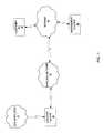
- FIG. 1is a high level diagram of a prior art wireless communication system.
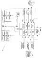
- FIG. 2is a block diagram of a dynamically configurable locator device according to one embodiment of the invention.
- FIG. 3is a block diagram of a System Software module of the dynamically configurable locator device shown in FIG. 2 .
- FIG. 4is a high level diagram illustrating a format of entries in a Profile Table stored in the dynamically configurable locator device shown in FIG. 2 .
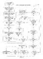
- FIG. 5is a flowchart illustrating the operation of a Profile Manager process running as a module of the System Software shown in FIG. 3 .
- FIG. 6is an illustration of a software profile configuration tool according to one embodiment of the invention.
- the wireless communication systemcomprises a plurality of locator devices 10 , a wireless network 12 , a plurality of GPS satellites 14 , the Internet 16 , a Management System 18 , and a plurality of customer computers 20 .
- the locator device 10is a wireless communication device, commonly installed in a vehicle or a trailer to provide location-based communication services such as, for example, asset tracking and reporting, Internet access, voice and text communications, and telemetry monitoring or control. Devices such as the locator devices 10 , albeit not containing the novel elements recited and claimed herein, are well known in the art.
- the locator devices 10obtain position information from the GPS satellites 14 via integrated or external GPS modems and antennas (not shown). Methods and apparatuses for obtaining GPS-based location information are well known in the art.
- WebTech LocatorTM devices mentioned aboveinclude integrated GPS modems.
- the locator devices 10are connected to the wireless communication network 12 , which may be any available cellular, satellite, microwave or radio communication network based on any communication standard such as, for example, GSM, GPRS, CDMA, CDPD or WiFi. Modes and methods of interconnection to such wireless communication networks are well known in the art and are not further described herein.
- the Management System 18is also connected to the wireless network 12 via the Internet 16 .
- the Management System 18provides portal-based locator device 10 management functions, such as remote device configuration and upgrades, data bridging, device monitoring, tracking and reporting, to Management System subscribers.
- the Management System 18is well known in the art and is not described further herein. For example, WebTech Wireless Inc. of Burnaby, British Columbia, produces and markets a Management System under the name Quadrant Vehicle Services SystemTM.
- the subscribers of the Management System 18access the Management System from PCs 20 using web browsers (not shown) or any another remote access method known in the art
- the locator device 10is shown in detail at 99 according to one embodiment of the invention.
- the locator device 10comprises a microprocessor 100 , an I/O interface 110 , a persistent memory 150 , a RAM 160 , a parameter memory 170 , and a Subscriber Identity Module (SIM) 180 .
- SIMSubscriber Identity Module
- the I/O interface 110enables communications between the locator device 10 and other devices, integrated or external.
- the I/O interface 110includes a plurality of telemetry interfaces.
- I/O interface 110includes an analog telemetry interface 112 , a digital telemetry interface 122 , a vehicle bus interface 114 , an RS232 interface 116 , a radio (RF) interface 118 , and a GPS interface 120 .
- the analog telemetry interface 112provides a connection 130 to a plurality of analog sensors (not shown) which generate variable voltage signals to indicate their status.
- a common example of an analog sensoris a thermometer (not shown), which outputs temperature measurements as a voltage-graduated analog signal.
- the analog telemetry interface 112further includes an analog-to-digital (A/D) converter (not shown), which converts received analog signals to their digital representations that can be further processed by the microprocessor 100 .
- A/D convertersThe operation of A/D converters is well-known in the art and is not described further herein.
- the digital telemetry interface 122provides a bidirectional connection to devices which generate, or are controlled by, digital signals. More specifically, the digital telemetry interface 122 includes a plurality of digital inputs 142 and plurality of digital outputs 143 .
- a common example of a device connected to the digital input 142is a door-mounted sensor which generates a logic HIGH signal when a door opens.
- a common example of a device connected to the digital output 143is a relay which controls some operational aspect of a vehicle in which it is installed, for example, disabling the vehicle's fuel pump upon receiving a logic HIGH signal from the digital telemetry interface 122 .
- the vehicle bus interface 114provides a bidirectional connection 132 to various vehicle systems, for example J1587/J1708, OBD II or CANBUS compliant systems.
- the GPS interface 120enables receiving GPS location information from the GPS satellites 14 through a GPS antenna 141 .
- the GPS interface 120may comprise an integrated or external GPS receiver and may further utilize any appropriate GPS antenna type.
- the WebTech 6000 LocatorTMfrom WebTech Wireless Inc. of Burnaby, British Columbia, integrates a GPS receiver and is typically equipped with an external active GPS antenna.
- the RF interface 118provides a wireless connection 118 to the wireless network 12 via a radio antenna 139 .
- the WebTech 6000 LocatorTM deviceintegrates a GSM/GPRS modem which can connect to any available GSM/GRPS network.
- the RF interface 118is further used to receive a remote computer data signal 144 from the Management System 18 .
- the RS232 interface 116provides a primary serial connection 134 and a secondary serial connection 136 .
- the primary serial connection 134typically connects to a computer or a navigation system co-located with the locator device 10 .
- the primary serial connection 134can be used for a variety of purposes, such as for local management of the locator device 10 via a laptop connected thereto that generates a local computer data signal 148 containing device commands. The meaning of the term ‘device commands’ will be described below.
- the primary serial connection 134can be connected to an in-vehicle navigation system to output thereto mapping and location information received from the Management System 18 and the GPS satellites 14 via the RF interface 118 and the GPS interface 120 , respectively.
- the secondary serial connection 136can be used to connect to a communication device, such as a satellite modem 146 , to provide a primary or a backup connection to the wireless network 12 via the radio antenna 139 or another antenna (not shown) appropriate for the specific type of wireless network 12 and the connection method used.
- the secondary serial connection 136via the satellite modem 146 , can be used to a re-establish a connection to the Management System 18 via a satellite communication network.
- interfaces comprising the I/O 110 described aboveare merely examples of possible configurations of the locator device 10 .
- a variety of interfaces, connections, and signalsmay be implemented in the locator device 10 as may be appropriate for a particular application.
- the persistent memory 150is a non-volatile memory which contains System Software 152 and a database of status records 154 .
- the database of status records 154is used to log and store all measurements and events received, processed or generated by the locator device 10 .
- the number of status records stored in the database of status records 154is limited only by the size of the non-volatile persistent memory 150 installed in the locator device 10 .
- the System Software 152comprises a collection of computer encoded instructions, which direct the microprocessor 100 to perform functions of the locator device 10 .
- the System Software 152will be described in further detail below in reference to FIG. 3 and FIG. 6 .
- the RAM 160is used by the locator device 10 to store various information of a temporary nature. Operation of the RAM 160 is well known in the art and will not be further described herein.
- the parameter memory 170is a non-volatile memory which contains a device configuration 172 , a Profile Table 176 , and a Geofence Table 178 .
- the device configuration 172is used to store a plurality of operational parameters which define all dynamically configurable operational aspects of the locator device 10 .
- the device configuration 172can also be modified by the Management System 18 , by a user operating a terminal connected to the primary serial connection 134 , or by the System Software 152 in response to occurrence of certain events.
- the Profile Table 176contains a plurality of event profiles which are used to dynamically respond to events by performing certain actions or changing the device configuration 172 . The meaning of the terms ‘events’ and ‘actions’ will be described below.
- the Geofence Table 178defines a plurality of geofences configured on the locator device 10 .
- a geofenceis a virtual boundary that can be configured on the locator device 10 using GPS co-ordinates. Geofences are typically configured on the locator device 10 by using device commands that are automatically generated by a software geofence configuration tool (not shown).
- a geofencecan define any area, for example, a work site, customer site, yard, home depot, area that should not be traveled through (exclusion fence), or any other type of area.
- the locator device 10when, based on the location information received from the GPS satellites 14 , the locator device 10 enters or leaves a geofence area, an event is generated and actions can be taken or device configuration 172 altered.
- the first typeis a polygon geofence created by drawing a polygon enclosing a desired area on a map.
- the second typeis a route geofence, a virtual boundary created along a designated route, which may span several hundred miles or kilometers.
- the route geofencecan be created along a tow truck operator's “Beat”, or an armored truck route along a stretch of highway between cities.
- the third typeis a circular geofence that is created by defining a center location and a radius.
- the SIM 180is used to store information that identifies the locator device 10 to the wireless network 12 .
- the use of SIM 180is well known in the art and will not be further described herein. A person skilled in the art will appreciate that, depending on the type of the wireless network 12 used with the particular locator device 10 , a different method for identification of the locator device to the wireless network may be used.
- the locator device 10may also be implemented using FPGA or ASIC technologies as alternative methods of encoding, storing and/or processing instructions which define the locator device operation.
- FPGAfield-programmable gate array
- ASICapplication-specific integrated circuit
- the System Software 152comprises a number of functional components including a Profile Manager 402 and Other System Modules 404 for implementing the functionality of the locator device 10 , a Command Interpreter 406 for managing the operation of the locator device, and Drivers 407 for controlling the interfaces 112 , 116 , 118 , 120 and 122 of the I/O 110 .
- the Profile Manager 402receives events from the drivers 407 via an event input 420 , processes the events according to triggers (as will be described below) to determine what event profile needs to be activated and what device commands need to be output to the Command Interpreter 406 via a command output 422 .
- the Command Interpreter 406provides a management interface to the locator device 10 by interpreting device commands to cause the locator device to perform actions or to change the device configuration 172 as specified in the commands.
- the device commands interpreted by the Command Interpreter 406can be received in the local computer data signal 148 from a local computer terminal, in the remote computer data signal 144 from the Management System 18 , or via the command output 422 from the Profile Manager 402 .
- the operation of the Profile Manager 402 and the meaning of the terms ‘events’, ‘triggers’, ‘event profiles’ and ‘actions’will be described below.
- Well known aspects of the locator device 10are implemented in the Other System Modules 404 and are not further described herein.
- the drivers 407include a wireless driver 410 , an RS232 driver 412 , a GPS driver 414 , and a telemetry driver 416 .
- the wireless driver 410enables communications to/from the wireless network 12 via the RF interface 118 .
- the wireless driver 410further enables transmitting and receiving the remote computer data signal 144 to and from the Management System 18 via the wireless network 12 (see FIG. 2 ). Where the remote computer data signal 144 contains device commands, they are forwarded by the wireless driver 410 to the Command Interpreter 406 .
- the RS232 driver 412enables communications to and from a local computer or data terminal via the primary serial connection 134 , and to/from a satellite network via the satellite modem 146 connected to the secondary serial connection 136 as previously described in reference to FIG. 2 .
- the RS232 driver 412forwards any received device commands to the Command Interpreter 406 .
- the GPS driver 414enables communication with the GPS interface 120 for receiving position information from the GPS satellites 14 as was previously described in reference to FIG. 2 .
- the telemetry driver 416enables communication to and from the vehicle bus interface 114 , the digital telemetry interface 122 and the analog telemetry interface 112 and devices connected thereto.
- the telemetry driver 416controls all operational aspects of these interfaces ( 112 , 114 , 122 ) enabling digital and analog output, and analog input via the A/D converter described above in reference to FIG. 2 .
- the telemetry driver 416may further enable advanced functions such as connection to a digital handset for voice communications through the locator device 10 .
- the drivers 407 described hereinare well known in the art and do not limit the function or the spirit of the invention as they may be implemented to enable any functionality required for a particular application of the locator device 10 .
- the Profile Manager 402 and the Command Interpreter 406 modules of the System Software 152control the operation of the locator device 10 by processing event profiles, events, triggers, device commands, configuration parameters and actions.
- event profiles‘events’, ‘triggers’, ‘device commands’, ‘configuration parameters’ and ‘actions’ in the context of this embodiment, are explained below.
- An event profileis a user-configurable dynamic association between (a) events and (b) device commands that represent actions and/or configuration parameters. More specifically, in the described embodiment, event profiles are stored in the Profile Table 176 in the format that will be described below in reference to FIG. 4 . Each event profile has a trigger, which is a dynamically configurable combination of events against which contemporaneous occurring events are evaluated to determine whether the event profile should become active. Each event profile also has a dynamically configurable collection of device commands which are output to the Command Interpreter 406 to implement the actions and/or configuration parameters associated with the active profile.
- An eventis an operational condition of the locator device 10 .
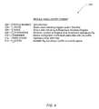
- a list of events, according to one embodiment of the invention,is shown in Table 1 below.
- geofence crossing events6 - 11 and 14 - 19
- geofence Table 178a single circular geofence is implemented and its information is also stored in the Geofence Table 178 .
- the Profile Manager 402accepts events as inputs and evaluates them according to event profile triggers to determine which event profile stored in the Profile Table 176 should be activated.
- a triggeris a dynamically configurable Boolean combination of events, which, in one embodiment of the invention, will cause the Profile Manager 402 to activate an event profile stored in the Profile Table 176 .
- the triggersmay be dynamically configured, i.e., the combination of events defined by device commands issued to the Command Interpreter 406 by (a) users via the primary serial connection 136 or via the Management System 18 , or (b) issued automatically by the Profile Manager 402 as a consequence of event processing.
- non-Boolean logic for defining dynamically configurable combinations of eventse.g., fuzzy logic or other forms of sequential or combinatorial logic
- a device commandis a string, formatted according to a pre-defined syntax, which conveys operational instructions and/or configuration parameters to the Command Interpreter 406 in order to make the locator device 10 perform an action or to change the device configuration 172 .
- An actionrepresents a function(s) of the locator device 10 , which can be implemented via one or more device command.
- an actionmay be turning on a specific telemetry output or sending an alarm to the in-vehicle navigation system connected to the primary serial interface 134 .
- configuration parametersare discrete aspects of the device configuration 172 which control specific operational aspects and/or functions of the locator device 10 .
- a configuration parametermay specify the frequency with which the locator device 10 will report to the Management System 18 or the mode of communication to be used to communicate with the Management System 18 —the RF interface 118 or the satellite modem 146 connected to secondary serial connection 136 as was described above in reference to FIG. 2 .
- Configuration parametersmay also specify entries in the Profile Table 176 or Geofence Table 178 .
- Each Profile Table 176 entrycomprises a P_NUM field 202 , a T_WORD field 204 , a T_MASK field 206 , a P_HYSTERESIS field 208 , a COMMANDS field 210 , a TIMER_START field 212 , and a P_ACTIVE flag 214 .
- the P_NUM field 202contains a priority number of the event profile described in the entry.
- Profile Table 176 entriesare evaluated in a sequential manner starting with an event profile with the highest number.
- a default event profilecontains 0 in the P_NUM field 202 and is activated when the received events do not correspond to the triggers of any other event profile in the Profile Table 176 .
- the T_WORD field 204defines a set of events which are evaluated for the event profile. Each bit of T_WORD field 204 corresponds to an event number, as can be seen in, for example, Table 1.
- the T_MASK field 206defines which events contained in the T_WORD field 204 are sufficient events and which ones are necessary events. Sufficient events will cause an event profile to be activated if any of sufficient events are occurring at the time of the evaluation. Necessary events will only cause an event profile to be activated if all of the necessary events are occurring at the time of the evaluation.
- a trigger for an event profileis defined by the combination of the contents of the T_WORD field 204 and the T_MASK field 206 , in effect, a Boolean expression for evaluating events.
- the P_HYSTERESIS field 208contains a numeric value defining a minimum duration during which the events (any sufficient or all necessary) defined in the T_WORD field 204 must be contemporaneously occurring to activate an event profile to which they correspond.
- the COMMANDS field 210contains a set of device commands which are output to the Command Interpreter 406 when an event profile is activated.
- the TIMER_START field 212is populated with a timestamp indicating a time when any of the sufficient or all of the necessary events were found to be occurring and a hysteresis timer (not shown) for the event profile was started.
- the P_ACTIVE flag 214is a Boolean flag indicating that the event profile is currently active, i.e., that the device commands contained in the configuration field 210 have been successfully processed by the Command Interpreter 406 .
- Profile Table 176 format described aboveis in the context of the described embodiment and is not a limiting aspect of the invention. Depending on a particular application, parameters or fields may be added to or removed from the event profile entries.
- FIG. 5operation of the Profile Manager 402 process according to one embodiment of the invention is shown in more detail at 300 .
- a person skilled in the artwill appreciate that a variety of methods and techniques may be used to implement the Profile Manager 402 process described herein. The process description provided below describes the implementation according to one embodiment of the invention and is not a limiting factor thereof.
- the operation of the Profile Manager 402 processbegins at the start of the duty cycle as shown at block 302 .
- the frequency of duty cyclesmay depend on a number of factors such as hardware components used, types of inputs/outputs processed, and the complexity of the locator device 10 .
- a duty cyclebegins every 0.1 seconds, i.e., at a frequency of 10 Hz.
- block 310directs the microprocessor 100 to evaluate all currently occurring events to create an ACT_T_WORD.
- block 312directs the microprocessor 100 to retrieve the first event profile entry from the Profile Table 176 .
- the first event profile entryis the event profile entry with the highest number contained in the P_NUM field 202 .
- block 314directs the microprocessor 100 to determine the sufficient events (STE) for the entry by performing a logical AND operation between the contents of the T_WORD field 204 and the T_MASK field 206 .
- Block 316then directs the microprocessor 100 to test the contemporaneous occurring events by performing a logical AND operation between STE and ACT_T_WORD.
- the microprocessor 100is directed to check whether the result of operation at block 316 is equal to zero. If no, then the sufficient events are present, and the microprocessor 100 is directed at block 327 to check whether the event profile entry corresponds to the currently active event profile by checking whether the P_ACTIVE flag 214 of the event profile entry is equal to TRUE. If yes, then no further processing is required and the microprocessor 100 is directed to end the duty cycle at block 350 .
- block 336directs the microprocessor 100 to check whether the hysteresis timer for the event profile entry has been started by checking if the TIMER_START field 212 of the event profile entry contains a valid timestamp. If the hysteresis timer has not yet been started, block 338 directs the microprocessor 100 to start the hysteresis timer for the event profile by writing the current time into the TIMER_START field 212 of the selected event profile entry. Once the hysteresis timer has been started at block 338 , the microprocessor 100 is directed to block 332 , the operation of which shall be described in further detail below.
- block 340directs the microprocessor 100 to check whether the time elapsed since the start of the hysteresis timer is greater than the hysteresis time defined in the P_HYSTERESIS field 208 of the selected event profile entry. If the elapsed time is greater than the value of the hysteresis time, block 342 directs the microprocessor 100 to forward the device commands contained in the COMMANDS field 210 of the event profile entry to the Command Interpreter 406 via the command output 422 described above in reference to FIG. 3 .
- block 344directs the microprocessor 100 to set the P_ACTIVE flag 214 in the event profile entry to TRUE and block 345 directs the microprocessor 100 to reset TIMER_START field 212 to 0.
- the microprocessor 100is then directed to end the duty cycle at block 350 . If, at block 340 , it is determined that the hysteresis timer has not yet expired, the microprocessor 100 is directed to block 332 , the operation of which shall be described below.
- block 320directs the microprocessor 100 to determine necessary events (RTE) for the entry by performing a logical XOR operation between the contents of the T_WORD field 204 and the T_MASK field 206 of the currently selected event profile entry.
- RTEnecessary events
- block 322directs the microprocessor 100 to test the currently occurring events by performing a logical AND operation between RTE and ACT_T_WORD.
- Block 324then directs the microprocessor 100 to check whether the result of the test is equal to RTE by performing a logical XOR operation between TEST determined at block 322 and RTE determined at block 320 .
- the microprocessor 100is directed to check if the result of the operation at block 324 is equal to 0. If so, the microprocessor 100 is directed to block 327 and so on as has been described above. If, at block 324 , it is determined that the necessary events are not present, block 328 directs the microprocessor 100 to check whether the currently selected event profile is also the currently active event profile by checking if the P_ACTIVE flag 214 in the event profile entry is set to TRUE.
- block 330directs the microprocessor 100 to set the P_ACTIVE flag 214 in the currently selected event profile to FALSE. In either situation, if the currently active event profile had to be deactivated at block 330 or, if the currently selected event profile is not the active event profile, the microprocessor 100 is directed to block 332 , the operation of which will be described in further detail below.
- Block 332directs the microprocessor 100 to check whether there are more event profile entries contained in the Profile Table 176 . If so, then block 334 directs the microprocessor 100 to retrieve the next event profile entry from the Profile Table 176 . The next event profile entry will have a number contained in P_NUM field 202 that will be smaller than the contents of the P_NUM field of the previously selected event profile entry. Once the next event profile entry is retrieved, the microprocessor 100 is directed to repeat procedure contained in blocks 312 through 350 as described above.
- block 346directs the microprocessor 100 to check whether the P_ACTIVE flag 214 in the default event profile is equal to TRUE. If so, then the default event profile is already active and the microprocessor 100 is directed to end the duty cycle at block 350 . If, at block 346 , it is determined that the default event profile is not currently active, block 348 directs the microprocessor 100 to forward the device commands contained in the COMMANDS field 210 of the default event profile entry to the Command Interpreter 406 via the command output 421 as described above in reference to FIG. 3 . Once the device commands have been accepted by the Command Interpreter 406 , block 349 directs the microprocessor 100 to set the P_ACTIVE flag 214 in the default event profile entry to TRUE and the microprocessor 100 is directed to end the duty cycle at block 350 .
- a software profile configuration toolis shown generally at 800 .
- the profile configuration tool 800can be used to add event profile entries to the Profile Table 176 by automatically generating a device command which will add an event profile entry to the table.
- the profile configuration tool 800can be run on a PC connected to the locator device 10 via the primary serial connection 134 or on a customer PC 20 connected to the Management System 18 via the Internet 16 .
- a user operating the profile configuration tool 800selects an event profile to be configured by selecting an appropriate radio-button from the list of available event profiles 806 .
- the number of event profilesis arbitrary and generally depends on the amount of memory and type of microprocessor 100 installed in the locator device 10 .
- the usercan define contents of the T_WORD field 204 and the T_MASK field 206 of the selected entry by clicking on a plurality of checkboxes 802 and 804 , which represent events previously illustrated in Table 1.
- a legend 822an unchecked checkbox indicates that an event is not used in the profile, a checkbox with a checkmark indicates that the event is a necessary event, and a checkbox with a filled square indicates that the event is a sufficient event.
- the useris able to select a value of the P_HYSTERESIS field 208 for the entry.
- a resulting event profile device command 810will be generated in a textbox 811 upon the user clicking on a Create Profile button 812 .
- the resulting event profile device command 810contains the event profile number at 819 , the T_WORD at 820 , the T_MASK at 824 , the P_HYSTERESIS at 826 and COMMANDS at 828 .
- the usercan use a Send Profile button 814 to upload the event profile to the locator device 10 .
- a person skilled in the artwill appreciate that functionality disclosed herein is not limited to uploading an event profile to a single locator device 10 . Rather, by integrating the profile configuration tool 800 with the Management System 18 , a single event profile may be simultaneously uploaded to a plurality of locator devices managed by the Management System.
- the profile configuration toolfurther provides functionality enabled by buttons 816 and 818 .
- a Get Profile button 816allows a user to download an event profile selected in field 806 from the locator device 10 .
- a Decode Profile button 818allows the user to translate the event profile downloaded via the Get Profile button 816 into a graphical representation in fields 802 , 804 , 808 and 809 .
- the locator device 10 and a specifically configured event profileare used to provide a truck driver with an audible and visual alarm when the driver exceeds a location-based speed limit defined by a truck operator.
- a location-based speed limitdefined by a truck operator.
- the drivermust maintain a speed below 50 km/h.
- the driveris allowed to maintain a speed of up to 80 km/h.
- an audible alarmis sounded, a visual indicator is lit, and the locator device 10 sends a report of the incident to the Management Server 18 from where it can be accessed by or automatically reported to the truck operator.
- the speed-threshold notification featureis a function implemented on the locator device 10 , specifically, certain configuration parameters in the device configuration 172 define the threshold speed limit and the digital I/O outputs 143 which are turned on to activate the audio-visual alarms.
- the city limitsare defined by a polygon geofence 1 which geographically encloses the city.
- a ‘rural’ event profileis defined. This trigger for this event profile is a single necessary event—event #7, crossing out of geofence 1, i.e., leaving the city limits.
- this event profilecauses the locator device 10 to automatically reconfigure itself to now only report speed limit violations when the speed exceeds 80 km/h. As soon as the truck crosses back into the city limits, the event #7 is no longer occurring, and thus the default event profile is loaded. A command contained in the default event profile reconfigures the locator device 10 to once again set the threshold speed limit to 50 km/h.
- an event profileaddresses a situation when a truck-and-trailer with the locator device 10 is parked in a storage yard or on a street.
- the trigger for this event profile(combination of T_WORD and T_MASK described above) consists of either two necessary events—event #5, indicating that the vehicle with the locator device 10 has crossed a geofence associated with physical area of the storage yard, and event #21, being physical input #1 is ON, indicating that a trailer is connected; or one sufficient trigger—event #26, being physical input #5 is ON, indicating that an alarm system has been armed.
- the hysteresis time for activation of this event profileis 0 seconds indicating that the event profile will become active as soon as all of the sufficient or necessary events are detected.
- the device commands associated with this event profiledefine actions—placing the locator device 10 into “sleep mode”, and configuration parameters—changing reporting interval to once in 6 hours and enabling monitoring of digital inputs associated with trailer door opening or the alarm system being tripped.
- the P_ACTIVE flag for this event profileis set to TRUE and remain so until one or more of the necessary events or all sufficient events become inactive.
- two event profilesare used to address a situation where a vehicle in which the locator device 10 is installed is being towed.
- Two event profilesare defined: a ‘parked’ profile and a ‘towed’ profile.
- the triggersare defined by two necessary events: event #50—physical input 14 is OFF, corresponding to vehicle ignition being OFF; and event #12—GPS fix established.
- the parked event profilehas a hysteresis of 180 seconds to make sure that the event profile does not become active if the vehicle merely stalls.
- the device commands associated with the parked profiledefine actions—placing the locator device in intermittent sleep mode, to wake up every 10 minutes to check conditions, and configuration parameters—configuring a security circular geofence and changing reporting interval to every 10 minutes to coincide with the locator device 10 waking up. Therefore, when a vehicle is parked and turned off, the parked event profile becomes activated, and the actions and configurations parameters described above are implemented.
- the towed event profilereconfigures the locator device 10 when the vehicle it is installed in is being towed outside of the security geofence—for example, it is being transported out of the city instead of being merely towed to an impound lot.
- the trigger for the towed event profileis defined by three necessary events: event #50 and event #12—same as for the parked profile, and event #5 indicating that the vehicle has crossed out of the circular geofence.
- the device commands associated with the towed profiledefine actions—wake up and report that vehicle that vehicle has left the circular geofence, and configuration parameters—change location reporting frequency to once every 15 seconds to allow vehicle to be initially located.
- an event profileis used to allow the fleet operator to save communication costs by using a cheaper GPRS network whenever possible and only switching to the expensive satellite network only when the GPRS network is unavailable.
- the trigger for this event profileis defined by two sufficient events—event #1 indicating that a PPP link with a wireless modem (reported by the wireless driver 410 ) is down, or event #2 indicating the PPP link is up, but only SMS communications to the Management System 18 are available, i.e., only a GSM network is available.
- a hysteresis value of 60 secondsis associated with the event profile to avoid ‘flapping’ between connections when the problem is transient.
- the device commands associated with this event profiledefine several configuration parameters needed to reconfigure the locator device 10 to connect to the Management System 18 via the satellite modem 146 connected to the secondary serial connection 136 as described above.
- the trigger for this event profilecan no longer be satisfied, thus, a default event profile, which reconfigures the locator device to once again use the GPRS network, is activated.
- an event profilecan be configured where the trigger is a combination of Virtual Input and Virtual Output events. These events are defined in the device configuration 172 as mapping a function of the vehicle bus interface 114 to a standard input or output event. For example, where a functionality of a vehicle bus provides reporting of an engine's revolutions per minute (RPM), the locator device 10 may be configured to map a threshold RPM value to a Virtual Input #1 going ON or OFF depending on whether the reported value is above or below a threshold. A similar mapping, but this time to a virtual output, can be done for a function of a vehicle bus system that accepts inputs from the locator device 10 . As above, the triggers which comprise these events can be used to correspond to actions or to reconfigure the locator device 10 , including reconfiguring of the mapping described in this example.
- RPMrevolutions per minute
Landscapes
- Business, Economics & Management (AREA)
- Engineering & Computer Science (AREA)
- Economics (AREA)
- Strategic Management (AREA)
- Entrepreneurship & Innovation (AREA)
- Human Resources & Organizations (AREA)
- Quality & Reliability (AREA)
- Operations Research (AREA)
- Marketing (AREA)
- Development Economics (AREA)
- Tourism & Hospitality (AREA)
- Physics & Mathematics (AREA)
- General Business, Economics & Management (AREA)
- General Physics & Mathematics (AREA)
- Theoretical Computer Science (AREA)
- Educational Administration (AREA)
- Game Theory and Decision Science (AREA)
- Position Fixing By Use Of Radio Waves (AREA)
- Mobile Radio Communication Systems (AREA)
Abstract
Description
| TABLE 1 | |
| Events Number | Event Description |
| 1 | PPP Context is inactive - Cellular Modem or wireless |
| network is down | |
| 2 | SMS - PPP context is active, but there is no host |
| connection | |
| 3 | TCP - PPP context is active, and there is a host |
| connection | |
| 4 | Circular geofence crossed into |
| 5 | Circular geofence crossed out of |
| 6 | geofence 1 crossing into |
| 7 | geofence 1 crossing out of |
| 8 | geofence 2 crossing into |
| 9 | geofence 2 crossing out of |
| 10 | geofence 3 crossing into |
| 11 | geofence 3 crossing out of |
| 12 | GPS fix occurs |
| 13 | GPS nofix occurs |
| 14 | geofence 4 crossing into |
| 15 | geofence 4 crossing out of |
| 16 | geofence 5 crossing into |
| 17 | geofence 5 crossing out of |
| 18 | geofence 6 crossing into |
| 19 | geofence 6 crossing out of |
| 20-35 | Physical Input 0-15 ON |
| 36-51 | Physical Input 0-15 OFF |
| 52-67 | Physical Output 0-15 ON |
| 68-83 | Physical Output 0-15 OFF |
| 84-99 | Virtual Input 0-15 ON |
| 100-115 | Virtual Input 0-15 OFF |
| 116-131 | Virtual Output 0-15 ON |
| 132-147 | Virtual Output 0-15 OFF |
| 148 | Main Power OFF |
| 149 | Battery Power ON |
| 150 | Low Battery |
| 151 | Timer 1 expired |
| 152 | Timer 1 running |
| 153 | Timer 2 expired |
| 154 | Timer 2 running |
| 155 | Timer 3 expired |
| 156 | Timer 3 running |
| 157 | In radio coverage |
| 158 | Out of radio coverage |
| 159 | Out of preferred wireless network |
Claims (23)
Priority Applications (3)
| Application Number | Priority Date | Filing Date | Title |
|---|---|---|---|
| US12/453,195US7940173B2 (en) | 2006-10-24 | 2009-05-01 | Dynamically configurable wireless device |
| US12/815,309US8587420B2 (en) | 2006-10-24 | 2010-06-14 | Unified vehicle parameters |
| US12/815,295US8766791B2 (en) | 2006-10-24 | 2010-06-14 | Configurable geofences with inherit aspects and use thereof in configurable wireless devices |
Applications Claiming Priority (2)
| Application Number | Priority Date | Filing Date | Title |
|---|---|---|---|
| US11/585,149US7538667B2 (en) | 2006-10-24 | 2006-10-24 | Dynamically configurable wireless device |
| US12/453,195US7940173B2 (en) | 2006-10-24 | 2009-05-01 | Dynamically configurable wireless device |
Related Parent Applications (1)
| Application Number | Title | Priority Date | Filing Date |
|---|---|---|---|
| US11/585,149ContinuationUS7538667B2 (en) | 2006-10-24 | 2006-10-24 | Dynamically configurable wireless device |
Related Child Applications (2)
| Application Number | Title | Priority Date | Filing Date |
|---|---|---|---|
| US12/815,309Continuation-In-PartUS8587420B2 (en) | 2006-10-24 | 2010-06-14 | Unified vehicle parameters |
| US12/815,295Continuation-In-PartUS8766791B2 (en) | 2006-10-24 | 2010-06-14 | Configurable geofences with inherit aspects and use thereof in configurable wireless devices |
Publications (2)
| Publication Number | Publication Date |
|---|---|
| US20090273469A1 US20090273469A1 (en) | 2009-11-05 |
| US7940173B2true US7940173B2 (en) | 2011-05-10 |
Family
ID=39317398
Family Applications (2)
| Application Number | Title | Priority Date | Filing Date |
|---|---|---|---|
| US11/585,149Active2028-01-18US7538667B2 (en) | 2006-10-24 | 2006-10-24 | Dynamically configurable wireless device |
| US12/453,195Active2029-08-06US7940173B2 (en) | 2006-10-24 | 2009-05-01 | Dynamically configurable wireless device |
Family Applications Before (1)
| Application Number | Title | Priority Date | Filing Date |
|---|---|---|---|
| US11/585,149Active2028-01-18US7538667B2 (en) | 2006-10-24 | 2006-10-24 | Dynamically configurable wireless device |
Country Status (2)
| Country | Link |
|---|---|
| US (2) | US7538667B2 (en) |
| CA (1) | CA2607465C (en) |
Cited By (22)
| Publication number | Priority date | Publication date | Assignee | Title |
|---|---|---|---|---|
| US20110225279A1 (en)* | 2010-03-12 | 2011-09-15 | Gm Global Technology Operations Llc. | Vehicle connectivity systems, methods, and applications |
| US20130301202A1 (en)* | 2012-05-08 | 2013-11-14 | Entegra Technologies, Inc | Reconfigurable Modular Computing Device |
| US9002379B1 (en) | 2014-02-24 | 2015-04-07 | Appsurdity, Inc. | Groups surrounding a present geo-spatial location of a mobile device |
| US9157742B1 (en)* | 2014-01-16 | 2015-10-13 | WI-MM Corporation | Cloud based activity monitor for bicycles and application |
| US9194955B1 (en) | 2014-01-16 | 2015-11-24 | WI-MM Corporation | Cloud based activity monitor for bicycles with fleet management and rider analytics system |
| US20160135005A1 (en)* | 2013-11-21 | 2016-05-12 | Microsoft Technology Licensing, Llc | Scalability and reliability of hardware geo-fencing with failover support |
| US9563893B2 (en) | 2012-10-16 | 2017-02-07 | Fleetcor Technologies Operating Company, Llc | Method and system for detection of a fuel card usage exception |
| US9880186B2 (en) | 2014-09-29 | 2018-01-30 | Laird Technologies, Inc. | Telematics devices and methods for vehicle speeding detection |
| US9904885B2 (en) | 2014-04-06 | 2018-02-27 | Vypin, LLC | Wireless medication compliance sensing device, system, and related methods |
| US9940615B2 (en) | 2012-10-16 | 2018-04-10 | Fleetcor Technologies Operating Company, Llc | Automated pairing of payment products and mobile to mobile devices |
| US10085116B2 (en) | 2016-09-23 | 2018-09-25 | International Business Machines Corporation | Matching actionable events with goods and services providers |
| US10108892B2 (en) | 2013-06-26 | 2018-10-23 | Vypin, LLC | Wireless tag apparatus and related medication compliance monitoring techniques |
| US10171936B2 (en) | 2016-09-23 | 2019-01-01 | International Business Machines Corporation | Matching actionable events with goods and services providers |
| US20190155307A1 (en)* | 2017-11-17 | 2019-05-23 | Polaris Industries Inc. | Method and System for Controlling the Speed of a Vehicle |
| US10438476B2 (en) | 2013-06-26 | 2019-10-08 | Vypin, LLC | Wireless hand hygiene tracking system and related techniques |
| US10510193B2 (en) | 2014-08-12 | 2019-12-17 | SVR Tracking, Inc. | Method and system for geofencing of vehicle impound yards |
| US10572700B2 (en) | 2013-06-26 | 2020-02-25 | Vypin, LLC | Wireless asset location tracking system and related techniques |
| US10796317B2 (en) | 2016-03-09 | 2020-10-06 | Talon Systems Software, Inc. | Method and system for auditing and verifying vehicle identification numbers (VINs) with audit fraud detection |
| US10896429B2 (en) | 2016-03-09 | 2021-01-19 | Talon Systems Software, Inc. | Method and system for auditing and verifying vehicle identification numbers (VINs) with crowdsourcing |
| US11037378B2 (en) | 2019-04-18 | 2021-06-15 | IGEN Networks Corp. | Method and system for creating driver telematic signatures |
| US11423417B2 (en) | 2016-03-09 | 2022-08-23 | Positioning Universal, Inc. | Method and system for auditing and verifying vehicle identification numbers (VINs) on transport devices with audit fraud detection |
| US11482057B2 (en) | 2019-12-14 | 2022-10-25 | SVR Tracking, Inc. | Method and system for battery management for mobile geofencing devices |
Families Citing this family (34)
| Publication number | Priority date | Publication date | Assignee | Title |
|---|---|---|---|---|
| WO2007073470A2 (en) | 2005-12-23 | 2007-06-28 | Perdiem, Llc | System and method for defining an event based on a relationship between an object location and a user-defined zone |
| US7525425B2 (en) | 2006-01-20 | 2009-04-28 | Perdiem Llc | System and method for defining an event based on relationship between an object location and a user-defined zone |
| US7912641B2 (en)* | 2006-06-14 | 2011-03-22 | Mts Technologies, Inc. | Vehicular fleet monitoring via public wireless communication access points using compressed diagnostic data sets and reduced latency transmissions |
| WO2009028647A1 (en)* | 2007-08-31 | 2009-03-05 | National Institute Of Information And Communications Technology | Non-dialogue learning device and dialogue learning device |
| US8535223B2 (en)* | 2008-02-28 | 2013-09-17 | Koninklijke Philips N.V. | Wireless patient monitoring using streaming of medical data with body-coupled communication |
| US8412231B1 (en)* | 2008-04-28 | 2013-04-02 | Open Invention Network, Llc | Providing information to a mobile device based on an event at a geographical location |
| US8219110B1 (en)* | 2008-04-28 | 2012-07-10 | Open Invention Network Llc | Providing information to a mobile device based on an event at a geographical location |
| US8923890B1 (en)* | 2008-04-28 | 2014-12-30 | Open Invention Network, Llc | Providing information to a mobile device based on an event at a geographical location |
| US8219312B2 (en)* | 2008-09-04 | 2012-07-10 | United Parcel Service Of America, Inc. | Determining speed parameters in a geographic area |
| US10453004B2 (en)* | 2008-09-04 | 2019-10-22 | United Parcel Service Of America, Inc. | Vehicle routing and scheduling systems |
| US20100100507A1 (en)* | 2008-09-04 | 2010-04-22 | United Parcel Service Of America, Inc. | Determining Vehicle Visit Costs To A Geographic Area |
| KR101570369B1 (en) | 2008-10-14 | 2015-11-20 | 엘지전자 주식회사 | Telematics terminal and method for controlling vehicle by using thereof |
| US8433296B2 (en) | 2009-05-01 | 2013-04-30 | Ryan Hardin | Exclusive delivery of content within geographic areas |
| US8570174B2 (en)* | 2009-06-01 | 2013-10-29 | Adel O. Sayegh | Pin alarm tag |
| US8456302B2 (en) | 2009-07-14 | 2013-06-04 | Savi Technology, Inc. | Wireless tracking and monitoring electronic seal |
| MX2012001497A (en) | 2009-08-14 | 2012-06-19 | Telogis Inc | Real time map rendering with data clustering and expansion and overlay. |
| CA2770755A1 (en)* | 2009-08-17 | 2011-02-24 | Deal Magic, Inc. | Contextually aware monitoring of assets |
| CN101673544B (en)* | 2009-10-10 | 2012-07-04 | 上海电虹软件有限公司 | Cross monitoring method and system based on voiceprint recognition and location tracking |
| US8983537B2 (en)* | 2009-12-30 | 2015-03-17 | Glenn Johnson | Object locator system and method |
| US8275508B1 (en)* | 2011-03-03 | 2012-09-25 | Telogis, Inc. | History timeline display for vehicle fleet management |
| CN102005131B (en)* | 2010-11-30 | 2014-04-16 | 理查德·乔纳森·李 | School bus forecasting system |
| US8688770B2 (en) | 2011-03-30 | 2014-04-01 | Webtech Wireless Inc. | System and method for job management between mobile devices |
| US8583319B2 (en)* | 2011-09-08 | 2013-11-12 | Webtech Wireless Inc. | System, method and odometer monitor for detecting connectivity status of mobile data terminal to vehicle |
| US8977427B2 (en) | 2011-09-08 | 2015-03-10 | Webtech Wireless Inc. | System, method and odometer monitor for detecting connectivity status of mobile data terminal to vehicle |
| US8896440B2 (en)* | 2012-05-24 | 2014-11-25 | Webtech Wireless Inc. | Event-triggered dynamic landmark creation system and method |
| US20140324714A1 (en)* | 2013-04-29 | 2014-10-30 | Omadi, Llc | Towing management |
| US9310221B1 (en) | 2014-05-12 | 2016-04-12 | Unmanned Innovation, Inc. | Distributed unmanned aerial vehicle architecture |
| US9256994B2 (en)* | 2014-05-12 | 2016-02-09 | Unmanned Innovation, Inc. | Unmanned aerial vehicle authorization and geofence envelope determination |
| CN105512583A (en)* | 2014-09-23 | 2016-04-20 | 深圳富泰宏精密工业有限公司 | System and method for concealed photography antitheft |
| US20160307447A1 (en) | 2015-02-13 | 2016-10-20 | Unmanned Innovation, Inc. | Unmanned aerial vehicle remote flight planning system |
| US10339536B2 (en)* | 2015-11-17 | 2019-07-02 | Schneider Enterprise Resources, LLC | Geolocation compliance for a mobile workforce |
| CN108099604B (en)* | 2017-11-28 | 2021-06-29 | 东风商用车有限公司 | Remote speed limiting method for commercial vehicle |
| CN108226975A (en)* | 2018-01-18 | 2018-06-29 | 北京港信科技有限公司 | Ship's fix monitoring system |
| US11961393B2 (en)* | 2021-08-11 | 2024-04-16 | Robert Christopher Webb | System and method for audible spatial description for people with sensory disabilities and the aging population |
Citations (23)
| Publication number | Priority date | Publication date | Assignee | Title |
|---|---|---|---|---|
| US5311197A (en)* | 1993-02-01 | 1994-05-10 | Trimble Navigation Limited | Event-activated reporting of vehicle location |
| WO1999034339A2 (en) | 1997-12-29 | 1999-07-08 | Ameritech Corporation | System and method for home automation and security |
| US5974312A (en) | 1997-07-10 | 1999-10-26 | Ericsson Inc. | System and method for updating a memory in an electronic device via wireless data transfer |
| US6031828A (en) | 1996-04-10 | 2000-02-29 | Oki Electric Industry Co., Ltd | Radio communication system |
| WO2000056016A1 (en) | 1999-03-15 | 2000-09-21 | Siemens Ag Österreich | Device for switching, controlling and monitoring appliances |
| WO2000070889A1 (en) | 1999-05-14 | 2000-11-23 | Medtronic Physio-Control Manufacturing Corp. | Method and apparatus for remote wireless communication with a medical device |
| WO2001003414A1 (en) | 1999-07-02 | 2001-01-11 | Musco Corporation | Means and apparatus for control of remote electrical devices |
| US6295449B1 (en) | 1992-01-27 | 2001-09-25 | @Track Communications, Inc. | Data messaging in a communications network using a feature request |
| US6314270B1 (en) | 1997-05-23 | 2001-11-06 | Matsushita Electric Industrial, Co., Ltd. | Fixed subscriber unit |
| US20030227395A1 (en)* | 2002-06-06 | 2003-12-11 | Advanced American Enterprises, Llc | Vehicular safety system and method |
| US20040012506A1 (en)* | 1996-09-13 | 2004-01-22 | Toshio Fujiwara | Information display system for displaying specified location with map therearound on display equipment |
| US6862524B1 (en) | 2001-07-03 | 2005-03-01 | At Road, Inc. | Using location data to determine traffic and route information |
| US6922547B2 (en) | 2001-06-27 | 2005-07-26 | Flarion Technologies, Inc. | Methods and apparatus for supporting group communications |
| US6934544B2 (en) | 2002-02-04 | 2005-08-23 | Qualcomm Incorporated | Method and apparatus for configurable selection and acquisition of a wireless communications system |
| US20060061469A1 (en)* | 2004-09-21 | 2006-03-23 | Skyfence Inc. | Positioning system that uses signals from a point source |
| US20060109106A1 (en)* | 2004-11-22 | 2006-05-25 | Maersk Logistics Usa, Inc. | Shipping container monitoring and tracking system |
| US20060187026A1 (en)* | 2002-05-07 | 2006-08-24 | Gary Kochis | Tracking system and associated method |
| US20060220842A1 (en)* | 2002-06-11 | 2006-10-05 | Automotive Technologies International, Inc. | Asset Monitoring Arrangement and Method |
| US20060238347A1 (en)* | 2005-04-22 | 2006-10-26 | W.R. Parkinson, Co., Inc. | Object tracking system |
| US20070156324A1 (en)* | 2001-12-31 | 2007-07-05 | Rdpa, Llc | Satellite positioning system enabled media measurement system and method |
| US20070219715A1 (en)* | 2004-04-06 | 2007-09-20 | Robert Uyeki | Bandwidth and memory conserving methods for a vehicle navigation system |
| US20080186162A1 (en)* | 2007-02-06 | 2008-08-07 | Qualcomm Incorporated | Apparatus and Methods for Locating, Tracking and/or Recovering a Wireless Communication Device |
| US7480563B2 (en)* | 2003-08-22 | 2009-01-20 | Fujitsu Ten Limited | Mobile object location providing device and mobile object location providing system |
- 2006
- 2006-10-24USUS11/585,149patent/US7538667B2/enactiveActive
- 2007
- 2007-10-23CACA2607465Apatent/CA2607465C/enactiveActive
- 2009
- 2009-05-01USUS12/453,195patent/US7940173B2/enactiveActive
Patent Citations (28)
| Publication number | Priority date | Publication date | Assignee | Title |
|---|---|---|---|---|
| US6295449B1 (en) | 1992-01-27 | 2001-09-25 | @Track Communications, Inc. | Data messaging in a communications network using a feature request |
| US5311197A (en)* | 1993-02-01 | 1994-05-10 | Trimble Navigation Limited | Event-activated reporting of vehicle location |
| US6031828A (en) | 1996-04-10 | 2000-02-29 | Oki Electric Industry Co., Ltd | Radio communication system |
| US20040012506A1 (en)* | 1996-09-13 | 2004-01-22 | Toshio Fujiwara | Information display system for displaying specified location with map therearound on display equipment |
| US6314270B1 (en) | 1997-05-23 | 2001-11-06 | Matsushita Electric Industrial, Co., Ltd. | Fixed subscriber unit |
| US5974312A (en) | 1997-07-10 | 1999-10-26 | Ericsson Inc. | System and method for updating a memory in an electronic device via wireless data transfer |
| WO1999034339A2 (en) | 1997-12-29 | 1999-07-08 | Ameritech Corporation | System and method for home automation and security |
| WO2000056016A1 (en) | 1999-03-15 | 2000-09-21 | Siemens Ag Österreich | Device for switching, controlling and monitoring appliances |
| WO2000070889A1 (en) | 1999-05-14 | 2000-11-23 | Medtronic Physio-Control Manufacturing Corp. | Method and apparatus for remote wireless communication with a medical device |
| WO2001003414A1 (en) | 1999-07-02 | 2001-01-11 | Musco Corporation | Means and apparatus for control of remote electrical devices |
| US6922547B2 (en) | 2001-06-27 | 2005-07-26 | Flarion Technologies, Inc. | Methods and apparatus for supporting group communications |
| US6862524B1 (en) | 2001-07-03 | 2005-03-01 | At Road, Inc. | Using location data to determine traffic and route information |
| US7408502B2 (en) | 2001-12-31 | 2008-08-05 | Rdpa, Llc | Satellite positioning system enabled business location planning |
| US20070156324A1 (en)* | 2001-12-31 | 2007-07-05 | Rdpa, Llc | Satellite positioning system enabled media measurement system and method |
| US6934544B2 (en) | 2002-02-04 | 2005-08-23 | Qualcomm Incorporated | Method and apparatus for configurable selection and acquisition of a wireless communications system |
| US20060187026A1 (en)* | 2002-05-07 | 2006-08-24 | Gary Kochis | Tracking system and associated method |
| US7196621B2 (en) | 2002-05-07 | 2007-03-27 | Argo-Tech Corporation | Tracking system and associated method |
| US20030227395A1 (en)* | 2002-06-06 | 2003-12-11 | Advanced American Enterprises, Llc | Vehicular safety system and method |
| US20060220842A1 (en)* | 2002-06-11 | 2006-10-05 | Automotive Technologies International, Inc. | Asset Monitoring Arrangement and Method |
| US7480563B2 (en)* | 2003-08-22 | 2009-01-20 | Fujitsu Ten Limited | Mobile object location providing device and mobile object location providing system |
| US20070219715A1 (en)* | 2004-04-06 | 2007-09-20 | Robert Uyeki | Bandwidth and memory conserving methods for a vehicle navigation system |
| US7451042B2 (en) | 2004-04-06 | 2008-11-11 | Honda Motor Co., Ltd. | Bandwidth and memory conserving methods for a vehicle navigation system |
| US20060061469A1 (en)* | 2004-09-21 | 2006-03-23 | Skyfence Inc. | Positioning system that uses signals from a point source |
| US7339469B2 (en) | 2004-11-22 | 2008-03-04 | Maersk Logistics Usa, Inc. | Shipping container monitoring and tracking system |
| US20080094209A1 (en)* | 2004-11-22 | 2008-04-24 | Maersk Logistics Usa, Inc. | Shipping container monitoring and tracking system |
| US20060109106A1 (en)* | 2004-11-22 | 2006-05-25 | Maersk Logistics Usa, Inc. | Shipping container monitoring and tracking system |
| US20060238347A1 (en)* | 2005-04-22 | 2006-10-26 | W.R. Parkinson, Co., Inc. | Object tracking system |
| US20080186162A1 (en)* | 2007-02-06 | 2008-08-07 | Qualcomm Incorporated | Apparatus and Methods for Locating, Tracking and/or Recovering a Wireless Communication Device |
Cited By (41)
| Publication number | Priority date | Publication date | Assignee | Title |
|---|---|---|---|---|
| US20110225260A1 (en)* | 2010-03-12 | 2011-09-15 | GM Global Technology Operations LLC | Vehicle Connectivity Systems, Methods and Applications |
| US20110224843A1 (en)* | 2010-03-12 | 2011-09-15 | GM Global Technology Operations LLC | Vehicle connectivity systems, methods, and applications |
| US20110225279A1 (en)* | 2010-03-12 | 2011-09-15 | Gm Global Technology Operations Llc. | Vehicle connectivity systems, methods, and applications |
| US9132715B2 (en)* | 2010-03-12 | 2015-09-15 | GM Global Technology Operations LLC | Vehicle connectivity systems, methods and applications |
| US9333833B2 (en) | 2010-03-12 | 2016-05-10 | Gm Global Techology Operations Llc | Vehicle connectivity systems, methods, and applications |
| US9227483B2 (en) | 2010-03-12 | 2016-01-05 | GM Global Technology Operations LLC | Vehicle connectivity systems, methods, and applications |
| US9213664B2 (en) | 2012-05-08 | 2015-12-15 | Entegra Technologies, Inc. | Reconfigurable modular computing device |
| US20130301202A1 (en)* | 2012-05-08 | 2013-11-14 | Entegra Technologies, Inc | Reconfigurable Modular Computing Device |
| US8751710B2 (en)* | 2012-05-08 | 2014-06-10 | Entegra Technologies, Inc. | Reconfigurable modular computing device |
| US8924609B2 (en) | 2012-05-08 | 2014-12-30 | Entegra Technologies, Inc. | Reconfigurable modular computing device |
| US9940615B2 (en) | 2012-10-16 | 2018-04-10 | Fleetcor Technologies Operating Company, Llc | Automated pairing of payment products and mobile to mobile devices |
| US9563893B2 (en) | 2012-10-16 | 2017-02-07 | Fleetcor Technologies Operating Company, Llc | Method and system for detection of a fuel card usage exception |
| US9576291B2 (en) | 2012-10-16 | 2017-02-21 | Fleetcor Technologies Operating Company, Llc | Method and system for detection of a fuel card usage exception |
| US10719672B2 (en) | 2013-06-26 | 2020-07-21 | Vypin, LLC | Wireless tag apparatus and related methods |
| US10318769B2 (en) | 2013-06-26 | 2019-06-11 | Vypin, LLC | Wireless tag apparatus and related methods |
| US10572700B2 (en) | 2013-06-26 | 2020-02-25 | Vypin, LLC | Wireless asset location tracking system and related techniques |
| US10438476B2 (en) | 2013-06-26 | 2019-10-08 | Vypin, LLC | Wireless hand hygiene tracking system and related techniques |
| US10108892B2 (en) | 2013-06-26 | 2018-10-23 | Vypin, LLC | Wireless tag apparatus and related medication compliance monitoring techniques |
| US10108893B2 (en) | 2013-06-26 | 2018-10-23 | Vypin, LLC | Sensor array, method of making same, and related medication compliance monitoring techniques |
| US10121028B2 (en) | 2013-06-26 | 2018-11-06 | Vypin, LLC | Asset tag apparatus and related methods |
| US20160135005A1 (en)* | 2013-11-21 | 2016-05-12 | Microsoft Technology Licensing, Llc | Scalability and reliability of hardware geo-fencing with failover support |
| US9749794B2 (en)* | 2013-11-21 | 2017-08-29 | Microsoft Technology Licensing, Llc | Scalability and reliability of hardware geo-fencing with failover support |
| US9157742B1 (en)* | 2014-01-16 | 2015-10-13 | WI-MM Corporation | Cloud based activity monitor for bicycles and application |
| US9194955B1 (en) | 2014-01-16 | 2015-11-24 | WI-MM Corporation | Cloud based activity monitor for bicycles with fleet management and rider analytics system |
| US9002379B1 (en) | 2014-02-24 | 2015-04-07 | Appsurdity, Inc. | Groups surrounding a present geo-spatial location of a mobile device |
| US9904885B2 (en) | 2014-04-06 | 2018-02-27 | Vypin, LLC | Wireless medication compliance sensing device, system, and related methods |
| US10510193B2 (en) | 2014-08-12 | 2019-12-17 | SVR Tracking, Inc. | Method and system for geofencing of vehicle impound yards |
| US9880186B2 (en) | 2014-09-29 | 2018-01-30 | Laird Technologies, Inc. | Telematics devices and methods for vehicle speeding detection |
| US9934622B2 (en) | 2014-09-29 | 2018-04-03 | Laird Technologies, Inc. | Telematics devices and methods for vehicle ignition detection |
| US10896429B2 (en) | 2016-03-09 | 2021-01-19 | Talon Systems Software, Inc. | Method and system for auditing and verifying vehicle identification numbers (VINs) with crowdsourcing |
| US11423417B2 (en) | 2016-03-09 | 2022-08-23 | Positioning Universal, Inc. | Method and system for auditing and verifying vehicle identification numbers (VINs) on transport devices with audit fraud detection |
| US10796317B2 (en) | 2016-03-09 | 2020-10-06 | Talon Systems Software, Inc. | Method and system for auditing and verifying vehicle identification numbers (VINs) with audit fraud detection |
| US10171936B2 (en) | 2016-09-23 | 2019-01-01 | International Business Machines Corporation | Matching actionable events with goods and services providers |
| US10085116B2 (en) | 2016-09-23 | 2018-09-25 | International Business Machines Corporation | Matching actionable events with goods and services providers |
| CN111344205A (en)* | 2017-11-17 | 2020-06-26 | 北极星工业有限公司 | Method and system for controlling vehicle speed |
| US10809741B2 (en)* | 2017-11-17 | 2020-10-20 | Polaris Industries Inc. | Method and system for controlling the speed of a vehicle |
| US20190155307A1 (en)* | 2017-11-17 | 2019-05-23 | Polaris Industries Inc. | Method and System for Controlling the Speed of a Vehicle |
| US11703884B2 (en) | 2017-11-17 | 2023-07-18 | Polaris Industries Inc. | Method and system for controlling the speed of a vehicle |
| CN111344205B (en)* | 2017-11-17 | 2023-08-22 | 北极星工业有限公司 | Method and system for controlling vehicle speed |
| US11037378B2 (en) | 2019-04-18 | 2021-06-15 | IGEN Networks Corp. | Method and system for creating driver telematic signatures |
| US11482057B2 (en) | 2019-12-14 | 2022-10-25 | SVR Tracking, Inc. | Method and system for battery management for mobile geofencing devices |
Also Published As
| Publication number | Publication date |
|---|---|
| US7538667B2 (en) | 2009-05-26 |
| CA2607465C (en) | 2015-05-19 |
| CA2607465A1 (en) | 2008-04-24 |
| US20080094256A1 (en) | 2008-04-24 |
| US20090273469A1 (en) | 2009-11-05 |
Similar Documents
| Publication | Publication Date | Title |
|---|---|---|
| US7940173B2 (en) | Dynamically configurable wireless device | |
| US8766791B2 (en) | Configurable geofences with inherit aspects and use thereof in configurable wireless devices | |
| WO2008128337A1 (en) | Configurable telematics and location-based system | |
| US11611868B2 (en) | Mobile transceiver having device-based alarm profile and a method of operation | |
| US20200296560A1 (en) | System and method for remote asset management | |
| JP5226850B2 (en) | A system for setting up and using geographic areas to monitor and control movable entities | |
| US8325025B2 (en) | Automated geo-fence boundary configuration and activation | |
| CA2671116C (en) | Vehicle communication device | |
| WO2000048058A2 (en) | Tracking, control, and logistics system and method | |
| KR20070094893A (en) | Methods and systems for monitoring and controlling devices using wireless media | |
| CN100414572C (en) | Road state information real-time publishing and applying system in city | |
| US7123927B2 (en) | Wireless data collecting system having transmission possibility determining means | |
| CN104345324A (en) | GPS vehicle positioning method and apparatus, and vehicle | |
| JP5014145B2 (en) | Set up and use geographic areas to monitor and control mobile entities | |
| CN212861711U (en) | Electric vehicle alarm, electric vehicle monitoring system and electric vehicle | |
| JP2025094670A (en) | Smart Meter Monitoring System | |
| JP2000285355A (en) | Position detecting device |
Legal Events
| Date | Code | Title | Description |
|---|---|---|---|
| AS | Assignment | Owner name:WEBTECH WIRELESS INC.,CANADA Free format text:ASSIGNMENT OF ASSIGNORS INTEREST;ASSIGNOR:KOEN, ROBERT JOHN;REEL/FRAME:024186/0825 Effective date:20071023 Owner name:WEBTECH WIRELESS INC., CANADA Free format text:ASSIGNMENT OF ASSIGNORS INTEREST;ASSIGNOR:KOEN, ROBERT JOHN;REEL/FRAME:024186/0825 Effective date:20071023 | |
| STCF | Information on status: patent grant | Free format text:PATENTED CASE | |
| FPAY | Fee payment | Year of fee payment:4 | |
| AS | Assignment | Owner name:THE TORONTO-DOMINION BANK, CANADA Free format text:SECURITY INTEREST;ASSIGNOR:WEBTECH WIRELESS INC.;REEL/FRAME:037895/0020 Effective date:20151030 | |
| AS | Assignment | Owner name:BSM TECHNOLOGIES LTD., CANADA Free format text:MERGER AND CHANGE OF NAME;ASSIGNORS:WEBTECH WIRELESS INC.;BSM TECHNOLOGIES LTD.;REEL/FRAME:047369/0579 Effective date:20160930 | |
| MAFP | Maintenance fee payment | Free format text:PAYMENT OF MAINTENANCE FEE, 8TH YR, SMALL ENTITY (ORIGINAL EVENT CODE: M2552); ENTITY STATUS OF PATENT OWNER: SMALL ENTITY Year of fee payment:8 | |
| AS | Assignment | Owner name:GEOTAB INC., CANADA Free format text:MERGER AND CHANGE OF NAME;ASSIGNORS:BSM TECHNOLOGIES LTD.;GEOTAB INC.;REEL/FRAME:052100/0360 Effective date:20191231 | |
| FEPP | Fee payment procedure | Free format text:ENTITY STATUS SET TO UNDISCOUNTED (ORIGINAL EVENT CODE: BIG.); ENTITY STATUS OF PATENT OWNER: LARGE ENTITY | |
| AS | Assignment | Owner name:GEOTAB INC., CANADA Free format text:RELEASE BY SECURED PARTY;ASSIGNOR:THE TORONTO-DOMINION BANK;REEL/FRAME:052697/0574 Effective date:20200319 | |
| AS | Assignment | Owner name:GEOTAB INC., CANADA Free format text:CORRECTIVE ASSIGNMENT TO CORRECT THE THE COVER SHEET, WHICH LISTED PATENT NUMBER 6377219 IN ERROR. THE CORRECT PATENT NUMBER IS 6377210 PREVIOUSLY RECORDED ON REEL 052697 FRAME 0574. ASSIGNOR(S) HEREBY CONFIRMS THE CORRECT LISTING OF PATENT 6377210 ON PAGE 6, ROW 8 OF THE ORIGINAL RELEASE OF SECURITY INTEREST.;ASSIGNOR:THE TORONTO-DOMINION BANK;REEL/FRAME:052718/0050 Effective date:20200319 | |
| MAFP | Maintenance fee payment | Free format text:PAYMENT OF MAINTENANCE FEE, 12TH YEAR, LARGE ENTITY (ORIGINAL EVENT CODE: M1553); ENTITY STATUS OF PATENT OWNER: LARGE ENTITY Year of fee payment:12 |