US7939051B2 - Hydrogen-producing fuel processing assemblies, heating assemblies, and methods of operating the same - Google Patents
Hydrogen-producing fuel processing assemblies, heating assemblies, and methods of operating the sameDownload PDFInfo
- Publication number
- US7939051B2 US7939051B2US11/751,417US75141707AUS7939051B2US 7939051 B2US7939051 B2US 7939051B2US 75141707 AUS75141707 AUS 75141707AUS 7939051 B2US7939051 B2US 7939051B2
- Authority
- US
- United States
- Prior art keywords
- hydrogen
- stream
- startup
- assembly
- region
- Prior art date
- Legal status (The legal status is an assumption and is not a legal conclusion. Google has not performed a legal analysis and makes no representation as to the accuracy of the status listed.)
- Expired - Fee Related, expires
Links
- UFHFLCQGNIYNRP-UHFFFAOYSA-NHydrogenChemical compound[H][H]UFHFLCQGNIYNRP-UHFFFAOYSA-N0.000titleclaimsabstractdescription316
- 239000001257hydrogenSubstances0.000titleclaimsabstractdescription236
- 229910052739hydrogenInorganic materials0.000titleclaimsabstractdescription236
- 239000000446fuelSubstances0.000titleclaimsabstractdescription207
- 238000010438heat treatmentMethods0.000titleclaimsabstractdescription132
- 238000000034methodMethods0.000titleclaimsabstractdescription42
- 238000012545processingMethods0.000titleabstractdescription85
- 238000000429assemblyMethods0.000titleabstractdescription55
- 230000000712assemblyEffects0.000titleabstractdescription55
- 238000002407reformingMethods0.000claimsabstractdescription61
- 238000000629steam reformingMethods0.000claimsabstractdescription61
- 230000008016vaporizationEffects0.000claimsabstractdescription34
- 238000009834vaporizationMethods0.000claimsabstractdescription31
- 239000006227byproductSubstances0.000claimsabstractdescription30
- 238000002485combustion reactionMethods0.000claimsabstractdescription24
- 229910052799carbonInorganic materials0.000claimsdescription56
- OKTJSMMVPCPJKN-UHFFFAOYSA-NCarbonChemical compound[C]OKTJSMMVPCPJKN-UHFFFAOYSA-N0.000claimsdescription55
- 239000007789gasSubstances0.000claimsdescription35
- 239000007788liquidSubstances0.000claimsdescription34
- XLYOFNOQVPJJNP-UHFFFAOYSA-NwaterSubstancesOXLYOFNOQVPJJNP-UHFFFAOYSA-N0.000claimsdescription33
- 239000003054catalystSubstances0.000claimsdescription25
- 239000000203mixtureSubstances0.000claimsdescription15
- 239000012528membraneSubstances0.000claimsdescription7
- UGFAIRIUMAVXCW-UHFFFAOYSA-NCarbon monoxideChemical compound[O+]#[C-]UGFAIRIUMAVXCW-UHFFFAOYSA-N0.000claimsdescription6
- 229910002091carbon monoxideInorganic materials0.000claimsdescription6
- 238000000926separation methodMethods0.000claimsdescription6
- 150000002431hydrogenChemical class0.000claimsdescription5
- 230000000977initiatory effectEffects0.000claimsdescription2
- 238000001179sorption measurementMethods0.000claimsdescription2
- 238000011144upstream manufacturingMethods0.000abstractdescription7
- OKKJLVBELUTLKV-UHFFFAOYSA-NMethanolChemical compoundOCOKKJLVBELUTLKV-UHFFFAOYSA-N0.000description57
- 238000000746purificationMethods0.000description46
- 239000000047productSubstances0.000description19
- 239000012530fluidSubstances0.000description15
- 238000004519manufacturing processMethods0.000description15
- LFQSCWFLJHTTHZ-UHFFFAOYSA-NEthanolChemical compoundCCOLFQSCWFLJHTTHZ-UHFFFAOYSA-N0.000description14
- 238000010276constructionMethods0.000description14
- 230000007246mechanismEffects0.000description11
- 238000004891communicationMethods0.000description10
- 238000004146energy storageMethods0.000description9
- 229930195733hydrocarbonNatural products0.000description8
- 150000002430hydrocarbonsChemical class0.000description8
- VNWKTOKETHGBQD-UHFFFAOYSA-NmethaneChemical compoundCVNWKTOKETHGBQD-UHFFFAOYSA-N0.000description8
- 238000003860storageMethods0.000description8
- 239000007795chemical reaction productSubstances0.000description6
- 239000011810insulating materialSubstances0.000description6
- 238000007726management methodMethods0.000description6
- 239000000463materialSubstances0.000description6
- 230000008901benefitEffects0.000description5
- 239000003981vehicleSubstances0.000description5
- ATUOYWHBWRKTHZ-UHFFFAOYSA-NPropaneChemical compoundCCCATUOYWHBWRKTHZ-UHFFFAOYSA-N0.000description4
- 238000006243chemical reactionMethods0.000description4
- 239000007800oxidant agentSubstances0.000description4
- 230000001590oxidative effectEffects0.000description4
- 239000004215Carbon black (E152)Substances0.000description3
- LYCAIKOWRPUZTN-UHFFFAOYSA-NEthylene glycolChemical compoundOCCOLYCAIKOWRPUZTN-UHFFFAOYSA-N0.000description3
- DNIAPMSPPWPWGF-UHFFFAOYSA-NPropylene glycolChemical compoundCC(O)CODNIAPMSPPWPWGF-UHFFFAOYSA-N0.000description3
- 150000001298alcoholsChemical class0.000description3
- 230000008569processEffects0.000description3
- 230000002829reductive effectEffects0.000description3
- 239000000126substanceSubstances0.000description3
- QGZKDVFQNNGYKY-UHFFFAOYSA-NAmmoniaChemical compoundNQGZKDVFQNNGYKY-UHFFFAOYSA-N0.000description2
- CURLTUGMZLYLDI-UHFFFAOYSA-NCarbon dioxideChemical compoundO=C=OCURLTUGMZLYLDI-UHFFFAOYSA-N0.000description2
- LCGLNKUTAGEVQW-UHFFFAOYSA-NDimethyl etherChemical compoundCOCLCGLNKUTAGEVQW-UHFFFAOYSA-N0.000description2
- MYMOFIZGZYHOMD-UHFFFAOYSA-NDioxygenChemical compoundO=OMYMOFIZGZYHOMD-UHFFFAOYSA-N0.000description2
- NBIIXXVUZAFLBC-UHFFFAOYSA-NPhosphoric acidChemical compoundOP(O)(O)=ONBIIXXVUZAFLBC-UHFFFAOYSA-N0.000description2
- 235000013844butaneNutrition0.000description2
- 230000003750conditioning effectEffects0.000description2
- 229910001882dioxygenInorganic materials0.000description2
- 230000005611electricityEffects0.000description2
- IJDNQMDRQITEOD-UHFFFAOYSA-Nn-butaneChemical compoundCCCCIJDNQMDRQITEOD-UHFFFAOYSA-N0.000description2
- 239000001294propaneSubstances0.000description2
- 230000001105regulatory effectEffects0.000description2
- 239000007787solidSubstances0.000description2
- 238000012546transferMethods0.000description2
- BVKZGUZCCUSVTD-UHFFFAOYSA-LCarbonateChemical compound[O-]C([O-])=OBVKZGUZCCUSVTD-UHFFFAOYSA-L0.000description1
- OTMSDBZUPAUEDD-UHFFFAOYSA-NEthaneChemical compoundCCOTMSDBZUPAUEDD-UHFFFAOYSA-N0.000description1
- VGGSQFUCUMXWEO-UHFFFAOYSA-NEtheneChemical compoundC=CVGGSQFUCUMXWEO-UHFFFAOYSA-N0.000description1
- 239000005977EthyleneSubstances0.000description1
- 229910000147aluminium phosphateInorganic materials0.000description1
- 150000001412aminesChemical class0.000description1
- 229910021529ammoniaInorganic materials0.000description1
- QVGXLLKOCUKJST-UHFFFAOYSA-Natomic oxygenChemical compound[O]QVGXLLKOCUKJST-UHFFFAOYSA-N0.000description1
- 230000003190augmentative effectEffects0.000description1
- 238000010923batch productionMethods0.000description1
- 239000001273butaneSubstances0.000description1
- 239000003990capacitorSubstances0.000description1
- 229910002092carbon dioxideInorganic materials0.000description1
- 239000001569carbon dioxideSubstances0.000description1
- 230000008859changeEffects0.000description1
- 239000000567combustion gasSubstances0.000description1
- 239000004020conductorSubstances0.000description1
- 238000013461designMethods0.000description1
- 238000009826distributionMethods0.000description1
- 238000005553drillingMethods0.000description1
- 238000005485electric heatingMethods0.000description1
- 239000003925fatSubstances0.000description1
- 239000003502gasolineSubstances0.000description1
- 150000004678hydridesChemical class0.000description1
- 125000004435hydrogen atomChemical group[H]*0.000description1
- 239000012535impuritySubstances0.000description1
- 238000009413insulationMethods0.000description1
- 239000003350keroseneSubstances0.000description1
- 230000000670limiting effectEffects0.000description1
- 239000003915liquefied petroleum gasSubstances0.000description1
- 238000012423maintenanceMethods0.000description1
- 229910052751metalInorganic materials0.000description1
- 239000002184metalSubstances0.000description1
- 150000002739metalsChemical class0.000description1
- 238000004377microelectronicMethods0.000description1
- 238000012544monitoring processMethods0.000description1
- OFBQJSOFQDEBGM-UHFFFAOYSA-Nn-pentaneNatural productsCCCCCOFBQJSOFQDEBGM-UHFFFAOYSA-N0.000description1
- 239000003345natural gasSubstances0.000description1
- 239000003921oilSubstances0.000description1
- 239000001301oxygenSubstances0.000description1
- 229910052760oxygenInorganic materials0.000description1
- 230000036961partial effectEffects0.000description1
- 229920005862polyolPolymers0.000description1
- 150000003077polyolsChemical class0.000description1
- QQONPFPTGQHPMA-UHFFFAOYSA-NpropyleneNatural productsCC=CQQONPFPTGQHPMA-UHFFFAOYSA-N0.000description1
- 125000004805propylene groupChemical group[H]C([H])([H])C([H])([*:1])C([H])([H])[*:2]0.000description1
- 230000001681protective effectEffects0.000description1
- 239000000376reactantSubstances0.000description1
- 230000009467reductionEffects0.000description1
- 230000008439repair processEffects0.000description1
- 230000004044responseEffects0.000description1
- 230000000717retained effectEffects0.000description1
- 239000004065semiconductorSubstances0.000description1
- 230000011664signalingEffects0.000description1
- 229910001220stainless steelInorganic materials0.000description1
- 239000010935stainless steelSubstances0.000description1
- 239000006200vaporizerSubstances0.000description1
Images


Classifications
- C—CHEMISTRY; METALLURGY
- C01—INORGANIC CHEMISTRY
- C01B—NON-METALLIC ELEMENTS; COMPOUNDS THEREOF; METALLOIDS OR COMPOUNDS THEREOF NOT COVERED BY SUBCLASS C01C
- C01B3/00—Hydrogen; Gaseous mixtures containing hydrogen; Separation of hydrogen from mixtures containing it; Purification of hydrogen
- C01B3/02—Production of hydrogen or of gaseous mixtures containing a substantial proportion of hydrogen
- C01B3/32—Production of hydrogen or of gaseous mixtures containing a substantial proportion of hydrogen by reaction of gaseous or liquid organic compounds with gasifying agents, e.g. water, carbon dioxide, air
- C01B3/34—Production of hydrogen or of gaseous mixtures containing a substantial proportion of hydrogen by reaction of gaseous or liquid organic compounds with gasifying agents, e.g. water, carbon dioxide, air by reaction of hydrocarbons with gasifying agents
- C01B3/38—Production of hydrogen or of gaseous mixtures containing a substantial proportion of hydrogen by reaction of gaseous or liquid organic compounds with gasifying agents, e.g. water, carbon dioxide, air by reaction of hydrocarbons with gasifying agents using catalysts
- C01B3/384—Production of hydrogen or of gaseous mixtures containing a substantial proportion of hydrogen by reaction of gaseous or liquid organic compounds with gasifying agents, e.g. water, carbon dioxide, air by reaction of hydrocarbons with gasifying agents using catalysts the catalyst being continuously externally heated
- B—PERFORMING OPERATIONS; TRANSPORTING
- B01—PHYSICAL OR CHEMICAL PROCESSES OR APPARATUS IN GENERAL
- B01J—CHEMICAL OR PHYSICAL PROCESSES, e.g. CATALYSIS OR COLLOID CHEMISTRY; THEIR RELEVANT APPARATUS
- B01J8/00—Chemical or physical processes in general, conducted in the presence of fluids and solid particles; Apparatus for such processes
- B01J8/02—Chemical or physical processes in general, conducted in the presence of fluids and solid particles; Apparatus for such processes with stationary particles, e.g. in fixed beds
- B01J8/04—Chemical or physical processes in general, conducted in the presence of fluids and solid particles; Apparatus for such processes with stationary particles, e.g. in fixed beds the fluid passing successively through two or more beds
- B01J8/0403—Chemical or physical processes in general, conducted in the presence of fluids and solid particles; Apparatus for such processes with stationary particles, e.g. in fixed beds the fluid passing successively through two or more beds the fluid flow within the beds being predominantly horizontal
- B01J8/0423—Chemical or physical processes in general, conducted in the presence of fluids and solid particles; Apparatus for such processes with stationary particles, e.g. in fixed beds the fluid passing successively through two or more beds the fluid flow within the beds being predominantly horizontal through two or more otherwise shaped beds
- B01J8/0426—Chemical or physical processes in general, conducted in the presence of fluids and solid particles; Apparatus for such processes with stationary particles, e.g. in fixed beds the fluid passing successively through two or more beds the fluid flow within the beds being predominantly horizontal through two or more otherwise shaped beds the beds being superimposed one above the other
- B—PERFORMING OPERATIONS; TRANSPORTING
- B01—PHYSICAL OR CHEMICAL PROCESSES OR APPARATUS IN GENERAL
- B01J—CHEMICAL OR PHYSICAL PROCESSES, e.g. CATALYSIS OR COLLOID CHEMISTRY; THEIR RELEVANT APPARATUS
- B01J8/00—Chemical or physical processes in general, conducted in the presence of fluids and solid particles; Apparatus for such processes
- B01J8/02—Chemical or physical processes in general, conducted in the presence of fluids and solid particles; Apparatus for such processes with stationary particles, e.g. in fixed beds
- B01J8/04—Chemical or physical processes in general, conducted in the presence of fluids and solid particles; Apparatus for such processes with stationary particles, e.g. in fixed beds the fluid passing successively through two or more beds
- B01J8/0496—Heating or cooling the reactor
- C—CHEMISTRY; METALLURGY
- C01—INORGANIC CHEMISTRY
- C01B—NON-METALLIC ELEMENTS; COMPOUNDS THEREOF; METALLOIDS OR COMPOUNDS THEREOF NOT COVERED BY SUBCLASS C01C
- C01B3/00—Hydrogen; Gaseous mixtures containing hydrogen; Separation of hydrogen from mixtures containing it; Purification of hydrogen
- C01B3/02—Production of hydrogen or of gaseous mixtures containing a substantial proportion of hydrogen
- C01B3/32—Production of hydrogen or of gaseous mixtures containing a substantial proportion of hydrogen by reaction of gaseous or liquid organic compounds with gasifying agents, e.g. water, carbon dioxide, air
- C01B3/34—Production of hydrogen or of gaseous mixtures containing a substantial proportion of hydrogen by reaction of gaseous or liquid organic compounds with gasifying agents, e.g. water, carbon dioxide, air by reaction of hydrocarbons with gasifying agents
- C01B3/38—Production of hydrogen or of gaseous mixtures containing a substantial proportion of hydrogen by reaction of gaseous or liquid organic compounds with gasifying agents, e.g. water, carbon dioxide, air by reaction of hydrocarbons with gasifying agents using catalysts
- C01B3/382—Multi-step processes
- B—PERFORMING OPERATIONS; TRANSPORTING
- B01—PHYSICAL OR CHEMICAL PROCESSES OR APPARATUS IN GENERAL
- B01J—CHEMICAL OR PHYSICAL PROCESSES, e.g. CATALYSIS OR COLLOID CHEMISTRY; THEIR RELEVANT APPARATUS
- B01J2208/00—Processes carried out in the presence of solid particles; Reactors therefor
- B01J2208/00008—Controlling the process
- B01J2208/00017—Controlling the temperature
- B01J2208/00389—Controlling the temperature using electric heating or cooling elements
- B01J2208/00398—Controlling the temperature using electric heating or cooling elements inside the reactor bed
- B—PERFORMING OPERATIONS; TRANSPORTING
- B01—PHYSICAL OR CHEMICAL PROCESSES OR APPARATUS IN GENERAL
- B01J—CHEMICAL OR PHYSICAL PROCESSES, e.g. CATALYSIS OR COLLOID CHEMISTRY; THEIR RELEVANT APPARATUS
- B01J2208/00—Processes carried out in the presence of solid particles; Reactors therefor
- B01J2208/00008—Controlling the process
- B01J2208/00017—Controlling the temperature
- B01J2208/00389—Controlling the temperature using electric heating or cooling elements
- B01J2208/00415—Controlling the temperature using electric heating or cooling elements electric resistance heaters
- B—PERFORMING OPERATIONS; TRANSPORTING
- B01—PHYSICAL OR CHEMICAL PROCESSES OR APPARATUS IN GENERAL
- B01J—CHEMICAL OR PHYSICAL PROCESSES, e.g. CATALYSIS OR COLLOID CHEMISTRY; THEIR RELEVANT APPARATUS
- B01J2208/00—Processes carried out in the presence of solid particles; Reactors therefor
- B01J2208/00008—Controlling the process
- B01J2208/00017—Controlling the temperature
- B01J2208/00504—Controlling the temperature by means of a burner
- B—PERFORMING OPERATIONS; TRANSPORTING
- B01—PHYSICAL OR CHEMICAL PROCESSES OR APPARATUS IN GENERAL
- B01J—CHEMICAL OR PHYSICAL PROCESSES, e.g. CATALYSIS OR COLLOID CHEMISTRY; THEIR RELEVANT APPARATUS
- B01J2208/00—Processes carried out in the presence of solid particles; Reactors therefor
- B01J2208/00008—Controlling the process
- B01J2208/00628—Controlling the composition of the reactive mixture
- B01J2208/00646—Means for starting up the reaction
- B—PERFORMING OPERATIONS; TRANSPORTING
- B01—PHYSICAL OR CHEMICAL PROCESSES OR APPARATUS IN GENERAL
- B01J—CHEMICAL OR PHYSICAL PROCESSES, e.g. CATALYSIS OR COLLOID CHEMISTRY; THEIR RELEVANT APPARATUS
- B01J2208/00—Processes carried out in the presence of solid particles; Reactors therefor
- B01J2208/00008—Controlling the process
- B01J2208/00716—Means for reactor start-up
- C—CHEMISTRY; METALLURGY
- C01—INORGANIC CHEMISTRY
- C01B—NON-METALLIC ELEMENTS; COMPOUNDS THEREOF; METALLOIDS OR COMPOUNDS THEREOF NOT COVERED BY SUBCLASS C01C
- C01B2203/00—Integrated processes for the production of hydrogen or synthesis gas
- C01B2203/02—Processes for making hydrogen or synthesis gas
- C01B2203/0205—Processes for making hydrogen or synthesis gas containing a reforming step
- C01B2203/0227—Processes for making hydrogen or synthesis gas containing a reforming step containing a catalytic reforming step
- C01B2203/0233—Processes for making hydrogen or synthesis gas containing a reforming step containing a catalytic reforming step the reforming step being a steam reforming step
- C—CHEMISTRY; METALLURGY
- C01—INORGANIC CHEMISTRY
- C01B—NON-METALLIC ELEMENTS; COMPOUNDS THEREOF; METALLOIDS OR COMPOUNDS THEREOF NOT COVERED BY SUBCLASS C01C
- C01B2203/00—Integrated processes for the production of hydrogen or synthesis gas
- C01B2203/04—Integrated processes for the production of hydrogen or synthesis gas containing a purification step for the hydrogen or the synthesis gas
- C—CHEMISTRY; METALLURGY
- C01—INORGANIC CHEMISTRY
- C01B—NON-METALLIC ELEMENTS; COMPOUNDS THEREOF; METALLOIDS OR COMPOUNDS THEREOF NOT COVERED BY SUBCLASS C01C
- C01B2203/00—Integrated processes for the production of hydrogen or synthesis gas
- C01B2203/06—Integration with other chemical processes
- C—CHEMISTRY; METALLURGY
- C01—INORGANIC CHEMISTRY
- C01B—NON-METALLIC ELEMENTS; COMPOUNDS THEREOF; METALLOIDS OR COMPOUNDS THEREOF NOT COVERED BY SUBCLASS C01C
- C01B2203/00—Integrated processes for the production of hydrogen or synthesis gas
- C01B2203/08—Methods of heating or cooling
- C01B2203/0805—Methods of heating the process for making hydrogen or synthesis gas
- C01B2203/0811—Methods of heating the process for making hydrogen or synthesis gas by combustion of fuel
- C—CHEMISTRY; METALLURGY
- C01—INORGANIC CHEMISTRY
- C01B—NON-METALLIC ELEMENTS; COMPOUNDS THEREOF; METALLOIDS OR COMPOUNDS THEREOF NOT COVERED BY SUBCLASS C01C
- C01B2203/00—Integrated processes for the production of hydrogen or synthesis gas
- C01B2203/08—Methods of heating or cooling
- C01B2203/0805—Methods of heating the process for making hydrogen or synthesis gas
- C01B2203/085—Methods of heating the process for making hydrogen or synthesis gas by electric heating
- C—CHEMISTRY; METALLURGY
- C01—INORGANIC CHEMISTRY
- C01B—NON-METALLIC ELEMENTS; COMPOUNDS THEREOF; METALLOIDS OR COMPOUNDS THEREOF NOT COVERED BY SUBCLASS C01C
- C01B2203/00—Integrated processes for the production of hydrogen or synthesis gas
- C01B2203/08—Methods of heating or cooling
- C01B2203/0805—Methods of heating the process for making hydrogen or synthesis gas
- C01B2203/0866—Methods of heating the process for making hydrogen or synthesis gas by combination of different heating methods
- C—CHEMISTRY; METALLURGY
- C01—INORGANIC CHEMISTRY
- C01B—NON-METALLIC ELEMENTS; COMPOUNDS THEREOF; METALLOIDS OR COMPOUNDS THEREOF NOT COVERED BY SUBCLASS C01C
- C01B2203/00—Integrated processes for the production of hydrogen or synthesis gas
- C01B2203/12—Feeding the process for making hydrogen or synthesis gas
- C01B2203/1288—Evaporation of one or more of the different feed components
- C—CHEMISTRY; METALLURGY
- C01—INORGANIC CHEMISTRY
- C01B—NON-METALLIC ELEMENTS; COMPOUNDS THEREOF; METALLOIDS OR COMPOUNDS THEREOF NOT COVERED BY SUBCLASS C01C
- C01B2203/00—Integrated processes for the production of hydrogen or synthesis gas
- C01B2203/14—Details of the flowsheet
- C01B2203/146—At least two purification steps in series
- C—CHEMISTRY; METALLURGY
- C01—INORGANIC CHEMISTRY
- C01B—NON-METALLIC ELEMENTS; COMPOUNDS THEREOF; METALLOIDS OR COMPOUNDS THEREOF NOT COVERED BY SUBCLASS C01C
- C01B2203/00—Integrated processes for the production of hydrogen or synthesis gas
- C01B2203/16—Controlling the process
- C01B2203/1604—Starting up the process
Definitions
- the present disclosureis related generally to hydrogen-producing fuel processing systems that are adapted to produce primarily hydrogen gas via a steam reforming reaction, and more particularly to systems and methods for initiating hydrogen production of the same.
- Purified hydrogen gasis used in the manufacture of many products including metals, edible fats and oils, and semiconductors and microelectronics. Purified hydrogen gas is also an important fuel source for many energy conversion devices. For example, fuel cells use purified hydrogen gas and an oxidant to produce an electrical potential. Various processes and devices may be used to produce the hydrogen gas that is consumed by the fuel cells. One such process is steam reforming, in which hydrogen gas is produced as a majority reaction product from a carbon-containing feedstock and water.
- Steam reforming of water and a carbon-containing feedstock to produce hydrogen gasis an endothermic reaction.
- Hydrogen-producing steam reforming reactionsare typically performed at elevated temperatures and pressures, such as temperatures of at least 200° C., and more typically at least 350° C., and pressures of at least 50 psi.
- the desired steam reforming temperature, or range of temperatureswill tend to vary according to a variety of factors, including the composition of the carbon-containing feedstock.
- steam reforming of methanol to produce hydrogen gasis typically performed at a temperature of 350-450° C., while many hydrocarbons are reformed to produce hydrogen gas at a temperature of 700-850° C.
- a hydrogen-producing steam reformerWhen a hydrogen-producing steam reformer is initially started up from an unheated, or off, operating state, at least the hydrogen-producing region of the steam reformer needs to be initially heated to at least a minimum hydrogen-producing temperature. Because the steam reforming reaction is endothermic, the hydrogen-producing region is often heated to above this minimum hydrogen-producing temperature before water and the carbon-containing feedstock are delivered thereto, typically in gaseous form, to produce hydrogen gas therefrom.
- a heating assemblyis typically utilized to provide the required preheating of the hydrogen-producing region, with burners, resistive heaters, and combustion catalysts being the most common sources of the required heating.
- Burners and combustion catalystsrequire the delivery of a suitable combustible fuel stream, the presence or delivery of a sufficient air stream to support the combustion, and suitable controls and delivery conduits to safely and reliably deliver and combust the fuel stream and to deliver the heated exhaust stream produced thereby to heat at least the hydrogen-producing region of the steam reformer.
- Electrically powered heatersrequire a sufficient power source for the heaters to generate sufficient heat throughout the hydrogen-producing region.
- FIG. 1is a schematic view of a steam reforming hydrogen generation assembly with a startup assembly according to the present disclosure.
- FIG. 2is a schematic view of another steam reforming hydrogen generation assembly with a startup assembly according to the present disclosure.
- FIG. 3is a schematic view of another steam reforming hydrogen generation assembly with a startup assembly according to the present disclosure.
- FIG. 4is a schematic view of another steam reforming hydrogen generation assembly with a startup assembly according to the present disclosure.
- FIG. 5is a schematic view of a hydrogen-producing fuel cell system according to the present disclosure.
- FIG. 6is a schematic view of another hydrogen-producing fuel cell system according to the present disclosure.
- FIG. 7is a schematic view of another hydrogen-producing fuel cell system according to the present disclosure.
- FIG. 8is a schematic view of another steam reforming hydrogen generation assembly according to the present disclosure.
- FIG. 9is a side elevation view of another illustrative startup assembly according to the present disclosure and a portion of a fuel processing assembly for use therewith.
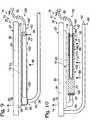
- FIG. 10is a side elevation view of another illustrative startup assembly according to the present disclosure and a portion of a fuel processing assembly for use therewith.
- FIG. 11is a bottom plan view of the startup assembly and the portion of fuel processing assembly of FIG. 10 .
- FIG. 12is a side elevation view of another illustrative startup assembly according to the present disclosure and a portion of a fuel processing assembly for use therewith.
- FIG. 13is an end elevation view of the another illustrative startup assembly according to the present disclosure and a portion of a fuel processing assembly for use therewith.
- FIG. 14is an end elevation view of the another illustrative startup assembly according to the present disclosure and a portion of a fuel processing assembly for use therewith.
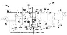
- Hydrogen generation assembly 10includes a feedstock delivery system 22 and a hydrogen-producing fuel processing assembly 31 .
- Fuel processing assembly, or system, 31is adapted to receive at least one feed stream 16 containing water 17 and a carbon-containing feedstock 18 from the feedstock delivery system.
- suitable carbon-containing feedstocks 18include at least one hydrocarbon or alcohol.
- suitable hydrocarbonsinclude methane, propane, natural gas, diesel, kerosene, gasoline and the like.
- suitable alcoholsinclude methanol, ethanol, and polyols, such as ethylene glycol and propylene glycol. While not required to all embodiments, in some embodiments the carbon-containing feedstock will be a liquid carbon-containing feedstock, and in some embodiments the carbon-containing feedstock will be miscible with water.
- the fuel processing assemblychemically reacts the water and the carbon-containing feedstock in the presence of a suitable steam reforming catalyst 23 and produces a product hydrogen stream 14 containing hydrogen gas as a majority component.
- the product hydrogen streamcontains pure, or at least substantially pure, hydrogen gas.
- Fuel processing assembly 31includes a hydrogen-producing region 19 , in which an output stream 20 containing hydrogen gas is produced by a steam reforming reaction that utilizes a suitable steam reforming catalyst 23 , as indicated in dashed lines in FIG. 1 .
- suitable steam reforming catalystsare disclosed in U.S. Patent Application Publication No. 2006/0236607, the complete disclosure of which is hereby incorporated by reference.
- Output stream 20includes hydrogen gas as at least a majority component.
- Output stream 20may include one or more additional gaseous components, and thereby may be referred to as a mixed gas stream that contains hydrogen gas as its majority component but which also includes other gases.
- gasesthat may be present in the reformate stream from the steam reforming reaction that occurs in hydrogen-producing region 19 include carbon monoxide, carbon dioxide, methane, steam, and/or unreacted carbon-containing feedstock.
- the fuel processing assembly 31may be referred to as a steam reformer
- hydrogen-producing region 19may be referred to as a reforming region
- output, or mixed gas, stream 20may be referred to as a reformate stream.
- hydrogen generation assemblies 10may, but are not required to, include at least one purification region 24 in which the concentration of hydrogen gas in output, or reformate, stream 20 is increased and/or the concentration of at least one of the other gases in the output stream is reduced.
- Purification region 24is schematically illustrated in FIG. 1 , where output stream 20 is shown being delivered to an optional purification region 24 .
- the purification regionmay separate the output stream into a hydrogen-rich stream 26 and a byproduct stream 28 .
- the product hydrogen streamcontains at least one of a greater concentration of hydrogen gas and/or a lower concentration of at least one of the other gases relative to the output stream.
- product hydrogen stream 14includes at least a portion of hydrogen-rich stream 26 . Accordingly, hydrogen-rich stream 26 and product hydrogen stream 14 may be the same stream and have the same compositions and flow rates. However, it is also within the scope of the present disclosure that some of the purified hydrogen gas in hydrogen-rich stream 26 may be stored for later use, such as in a suitable hydrogen storage assembly, and/or consumed by the fuel processing assembly.
- Byproduct stream 28contains at least a substantial portion of one or more of the other gases and may, but is not required to, include some hydrogen gas. When present, byproduct stream 28 may be exhausted, sent to a burner assembly or other combustion source, used as a heated fluid stream, stored for later use, or otherwise utilized, stored, or disposed of. It is within the scope of the disclosure that byproduct stream 28 may be emitted from the purification region as a continuous stream, such as responsive to the delivery of output stream 20 to the purification region, or intermittently, such as in a batch process or when the byproduct portion of the output stream is retained at least temporarily in the purification region.
- the byproduct streammay contain sufficient hydrogen gas and/or combustible other gases that the byproduct stream may be used as a gaseous fuel stream for a burner, combustion region, or other heating assembly that is adapted to combust a fuel stream in the presence of air to produce a heated output stream.
- hydrogen generation assembly 10may include such a heating assembly that is adapted to combust the byproduct stream to produce a heated output stream, or heated exhaust stream, to heat at least the hydrogen-producing region of the fuel processing assembly.
- the byproduct streammay have sufficient fuel value (i.e., hydrogen gas content) to enable the heating assembly, when present, to maintain the hydrogen-producing region at a desired operating (i.e. hydrogen-producing) temperature, above a minimum hydrogen-producing temperature, and/or within a selected range of temperatures.
- the byproduct streammay include hydrogen gas, such as 10-30 wt % hydrogen gas, 15-25 wt % hydrogen gas, 20-30 wt % hydrogen gas, at least 10 or 15 wt % hydrogen gas, at least 20 wt % hydrogen gas, etc.
- hydrogen gassuch as 10-30 wt % hydrogen gas, 15-25 wt % hydrogen gas, 20-30 wt % hydrogen gas, at least 10 or 15 wt % hydrogen gas, at least 20 wt % hydrogen gas, etc.
- hydrogen generation assembly 10requires a heat source, or heating assembly, 60 that is adapted to heat at least hydrogen-producing region 19 of the fuel processing assembly to a suitable temperature, or range of temperatures, for producing hydrogen gas therein and to maintain the hydrogen-producing region at this temperature, or within this temperature range, while the hydrogen-producing region is needed to produce hydrogen gas.
- a heat sourceor heating assembly, 60 that is adapted to heat at least hydrogen-producing region 19 of the fuel processing assembly to a suitable temperature, or range of temperatures, for producing hydrogen gas therein and to maintain the hydrogen-producing region at this temperature, or within this temperature range, while the hydrogen-producing region is needed to produce hydrogen gas.
- steam reformerstypically operate at temperatures in the range of 200° C. and 900° C. Temperatures outside of this range are within the scope of the disclosure.
- the steam reforming reactionwill typically operate in a temperature range of approximately 200-500° C. Illustrative subsets of this range include 350-450° C., 375-425° C., and 375-400° C.
- a temperature range of approximately 400-900° C.will typically be used for the steam reforming reaction.
- Illustrative subsets of this rangeinclude 750-850° C., 725-825° C., 650-750° C., 700-800° C., 700-900° C., 500-800° C., 400-600° C., and 600-800° C.
- the hydrogen-producing regionmay include two or more zones, or portions, each of which may be operated at the same or at different temperatures.
- the carbon-containing feedstockincludes a hydrocarbon
- the fuel processing systemmay alternatively be described as including two or more hydrogen-producing regions, and/or as including two or more hydrogen-producing regions that are connected in series, with the output stream from the first region forming at least a portion of the feed stream for the second hydrogen-producing region.
- fuel processing assembly 31includes a hydrogen-producing region 19 and a heating assembly 60 .
- Heating assembly 60is adapted to produce a heated exhaust stream, or combustion stream, 66 from heating fuel stream 64 , typically as combusted in the presence of air.
- Stream 66is schematically illustrated in FIG. 1 as heating hydrogen-producing region 19 , such as to a suitable hydrogen-producing temperature or range of temperatures.
- Heating assembly 60may utilize any suitable structure for generating heated exhaust stream 66 , such as a burner or combustion catalyst in which a fuel is combusted with air to produce the heated exhaust stream.
- Heating assembly 60may include an ignitor, or ignition source, 89 that is adapted to initiate the combustion of fuel, and thereby the generation of exhaust stream 66 .
- ignition sourcesinclude one or more of spark plugs, glow plugs, combustion catalyst, pilot lights, piezoelectric ignitors, and the like.
- heating assembly 60includes a burner assembly 62 and may be referred to as a combustion-based, or combustion-driven, heating assembly.
- the heating assembly 60is adapted to receive at least one fuel stream 64 and to combust the fuel stream in the presence of air to provide a hot combustion stream 66 that may be used to heat at least the hydrogen-producing region 19 of the fuel processing assembly.
- airmay be delivered to the heating assembly via a variety of mechanisms. In FIG.
- an air stream 74is shown; however, it is within the scope of the disclosure for the air stream to additionally or alternatively be delivered to the heating assembly with at least one of the fuel streams 64 for the heating assembly 60 and/or drawn from the environment within which the heating assembly is utilized.
- Illustrative, non-exclusive examples of burner assemblies that may be utilized in hydrogen-producing fuel processing systemsare disclosed in U.S. Patent Application Publication Nos. 2003/0223926 and 2006/0090397, the complete disclosures of which are hereby incorporated by reference for all purposes.
- combustion stream 66may additionally or alternatively be used to heat other portions of the fuel processing assembly. It is also within the scope of the present disclosure that other configurations and types of heating assemblies 60 may be utilized. As an illustrative example, a heating assembly 60 may be an electrically powered heating assembly that is adapted to heat at least the hydrogen-producing region of the fuel processing assembly by generating heat using at least one heating element, such as a resistive heating element. Therefore, it is not required that heating assembly 60 receive and combust a combustible fuel stream to heat hydrogen-producing region 19 to a suitable hydrogen-producing temperature.
- heating assembliesthat may be utilized in hydrogen generation assemblies, hydrogen-producing fuel processing assemblies, and the like according to the present disclosure are disclosed in U.S. Patent Application Publication No. 2006/0272212, the complete disclosure of which is hereby incorporated by reference for all purposes.
- heating assembly 60is housed in a common shell, or housing, 68 with the hydrogen-producing region and/or purification region(s), although this construction is not required. It is also within the scope of the present disclosure that the heating assembly may be separately positioned relative to the hydrogen-producing region but in thermal and/or fluid communication therewith to provide the desired heating of at least the hydrogen-producing region.
- heating assembly 60is shown in an overlapping relationship with fuel processing assembly 31 to graphically represent that it is within the scope of the disclosure that the heating assembly may be located partially or completely within fuel processing assembly 31 , such as being at least partially within shell 68 , and/or that at least a portion, or all, of the heating assembly may be located external the fuel processing assembly. In this latter embodiment, the hot combustion gases from the burner assembly will be delivered via suitable heat transfer conduits to the hydrogen-producing region or other portion of the assembly to be heated.
- heating assembly 60may be configured to heat the feedstock delivery system, the at least one feed stream emitted therefrom, the hydrogen-producing region, the purification (or separation) region, or any combination of these elements or selected components thereof.
- the heating of the one or more feed streamsmay include vaporizing liquid components of the feed stream(s).
- the heating assembly 60may also be configured to heat other components of the hydrogen generation assembly 10 .
- the heated exhaust streammay be adapted to heat a pressure vessel or other canister containing the heating fuel and/or the hydrogen-production fluid that form at least portions of streams 16 and 64 . While not required, increasing the temperature of a vessel may increase the pressure of the fluids stored within the vessel, which may be desirable in some applications.
- Hydrogen generation assemblies 10may include a feedstock delivery system 22 that is adapted to selectively deliver at least one feed stream 16 to at least the hydrogen-producing region of the fuel processing assembly.
- the feedstock delivery systemis further adapted to at least selectively deliver fuel stream 64 to a burner 62 , combustion catalyst, or other heating assembly 60 that is adapted to heat at least the hydrogen-producing region 19 , such as to heat (and optionally maintain) the region at a suitable hydrogen-producing temperature.
- Feedstock delivery system 22may utilize any suitable delivery mechanism. In the embodiment shown schematically in FIG.
- feedstock delivery system 22is adapted to deliver two feedstock supply streams 11 , namely, a feed stream, or hydrogen-production fluid supply stream, 16 , which contains water 17 and a carbon-containing feedstock 18 and is adapted to be delivered to hydrogen-producing region 19 of the fuel processing system, and a heating fuel supply stream 64 , which contains at least one combustible fuel 13 and is adapted to be delivered to heating assembly 60 .
- feedstock delivery system 22will not deliver a fuel or other stream to heating assembly 60 .
- heating assembly 60may be adapted to receive only byproduct stream 28 (and optionally a portion of hydrogen-rich stream 26 ) as its combustible fuel stream.
- FIG. 1While a single feed stream 16 is shown in FIG. 1 , it is within the scope of the disclosure that more than one stream 16 may be used and that these streams may contain the same or different feedstocks. This is schematically illustrated by the inclusion of a second feed stream 16 in dashed lines in FIG. 1 . Similarly, FIG. 1 also illustrates in dashed lines that each feed stream 16 may (but is not required to) be associated with a different feedstock delivery system 22 , or portions thereof. For example, when more than one feedstock delivery system 22 is utilized, the systems may (but are not required to) draw at least a portion of their outlet streams from a common supply. When feed stream 16 contains two or more components, such as a carbon-containing feedstock and water, the components may be delivered in the same or different feed streams.
- feed stream 16contains two or more components, such as a carbon-containing feedstock and water, the components may be delivered in the same or different feed streams.
- the feedstock delivery systemmay be (but is not required to be) adapted to deliver a liquid feed stream 16 that contains a mixture of water and the carbon-containing feedstock.
- the ratio of water to carbon-containing feedstock in such a feed streammay vary according to such factors as the particular carbon-containing feedstock being used, user preferences, the design of the hydrogen-production region, etc. Typically the molar ratio of water to carbon will be approximately 1:1 to 3:1.
- Mixtures of water and methanolwill often be delivered at or near a 1:1 molar ratio (31 vol % water, 69 vol % methanol), while mixtures of hydrocarbons or other alcohols will often be delivered at a molar ratio greater than 1:1 water-to-carbon.
- a reforming feed stream 16may contain approximately 25-75 vol % methanol or ethanol or another suitable water-miscible carbon-containing feedstock, and approximately 25-75 vol % water.
- the streamswill typically contain approximately 50-75 vol % methanol and approximately 25-50 vol % water.
- Streams containing ethanol or other water-miscible alcoholswill typically contain approximately 25-60 vol % alcohol and approximately 40-75 vol % water.
- An example of a particularly well-suited feed stream for hydrogen-generating assemblies that utilize steam reforming reactionscontains 69 vol % methanol and 31 vol % water, although other compositions and liquid carbon-containing feedstocks may be used without departing from the scope of the present disclosure.
- such a feed stream that contains both water and at least one carbon-containing feedstockmay be used as the feed stream for hydrogen-producing region 19 and as a combustible fuel stream for a heating assembly that is adapted to heat at least the hydrogen-producing region of the fuel processing assembly.
- a potential benefit of such a constructionis that the hydrogen generation assembly that produces hydrogen gas from water and a carbon-containing feedstock does not need to include more than a single supply 112 , if the water and water-soluble liquid carbon-containing feedstock are premixed.
- a feedstock delivery system 22may deliver the components of the hydrogen production fluid, or feed stream, to the fuel processing assembly in two or more streams, with these streams having the same or different compositions.
- the carbon-containing feedstock and watermay be delivered in separate streams, and optionally (at least until both streams are vaporized or otherwise gaseous), when they are not miscible with each other, such as shown in FIG. 1 by reference numerals 17 and 18 optionally pointing to different feed streams.
- heating fuel 13may include any combustible liquid and/or gas that is suitable for being consumed by heating assembly 60 to provide the desired heat output.
- Some heating fuels 13 according to the present disclosurewill be gases when delivered and combusted by heating assembly 60 , while others will be delivered to the heating assembly as a liquid stream.
- suitable heating fuelsinclude the previously discussed carbon-containing feedstocks, such as methanol, methane, ethane, ethanol, ethylene, propane, propylene, butane, and butanes, amongst others.
- the heating fuel stream and the hydrogen-production fluid streammay have different individual or overall compositions and may be discharged from the feedstock delivery system in different phases.
- one of the streamsmay be a liquid stream while the other is a gas stream.
- both of the streamsmay be liquid streams.
- both of the streamsmay be gas streams.
- suitable feedstock delivery systems 22that may be used with hydrogen-producing fuel processing assemblies (or hydrogen-generation assemblies) according to the present disclosure are disclosed in U.S. Patent Application Publication Nos. 2007/0062116, 2006/0090396, and 2006/0090397.
- the complete disclosures of the above-identified patent applicationsare hereby incorporated by reference for all purposes.
- the above-incorporated applicationsalso disclose additional examples of fuel processing assemblies, fuel cell systems, the components therefor, and methods for operating the same that may selectively be used and/or integrated with other components disclosed, illustrated and/or incorporated herein.
- Illustrative, nonexclusive examples of suitable hydrogen generation assemblies, and components thereof,are disclosed in U.S. Pat. Nos.
- steam reforming hydrogen generation assemblies 10include a heating assembly 60 that is adapted to maintain the hydrogen-producing region 19 at a suitable temperature, or within a suitable temperature range, for producing hydrogen gas by steam reforming water and a carbon-containing feedstock.
- a suitable hydrogen-producing temperaturesuch as when the hydrogen generation assembly is started up from a cold, or unheated, operating state.
- a fuel streamis delivered to heating assembly 60 , either by feedstock delivery system 22 or by a suitable fuel delivery system.
- the hydrogen-producing regionmust be heated by heating assembly 60 to a suitable hydrogen-producing temperature. While reasonably effective, the time and/or energy/fuel requirements to heat hydrogen-producing region 19 to this temperature may be more than is desirable in some embodiments.
- Hydrogen generation assemblies 10include a startup assembly, or preheating assembly, 120 that is adapted to receive feed stream(s) 16 and to vaporize any liquid component thereof. Accordingly, startup assembly 120 may be described as including a vaporization region 122 , in which liquid portions of the feed stream or streams are vaporized.
- the at least one feed stream 16is delivered from the feedstock delivery system as a liquid stream, such as a liquid stream that contains water and a liquid carbon-containing feedstock.
- at least a portion of the feed stream, such as the carbon-containing feedstock portion thereofmay be delivered as a gas stream.
- many hydrocarbonsare gases under the temperature and pressure at which they are delivered by a suitable feedstock delivery system.
- the feedstock delivery systemwill be described as being adapted to deliver a liquid feed stream that includes water and a liquid carbon-containing feedstock, such as methanol, that is miscible with water.
- a liquid carbon-containing feedstocksuch as methanol
- Other compositions and numbers of feed streamsare within the scope of the present disclosure, as discussed herein.
- startup assembly 120may also include a steam reforming catalyst 23 that defines a startup reforming region 130 in which some hydrogen gas is produced from the vaporized feed stream via a steam reforming reaction.
- Startup reforming region 130is upstream and spaced-apart from hydrogen-producing region 19 , which may be referred to as a primary reforming region or a primary steam reforming region.
- upstream and downstreamrespectively refer to the relative position of various components and/or regions of the fuel processing assembly with respect to fluid flow thereto. For example, when startup reforming region is described as being upstream from hydrogen-producing region 19 , it is meant that fluid from startup reforming region flows (directly or indirectly) to the hydrogen-producing region.
- hydrogen-producing region 19may be described as being downstream from the startup reforming region because it receives fluid (directly or indirectly) from the startup reforming region.
- the feedstock delivery systemmay be described as being upstream from startup reforming region 130 and hydrogen-producing region 19 because fluid from the feedstock delivery system flows to the startup reforming region and then to the hydrogen-producing region, although the relative flow rate and composition of this fluid stream may change as it flows (and is reacted) from the feedstock delivery system to downstream components of the fuel processing assembly.
- a purification regionif present, may be described as being downstream from feedstock delivery system 22 , startup reforming region 130 , and hydrogen-producing region 19 because the hydrogen-gas containing stream it receives originates as a feed stream from the feedstock delivery system.
- Startup reforming region 130is adapted to convert at least a portion of the vaporized feed stream to hydrogen gas prior to delivery of the remaining feed stream (and any produced hydrogen gas and other steam reforming reaction products) to hydrogen-producing region 19 .
- Startup reforming region 130will typically contain less steam reforming catalyst 23 than hydrogen-producing region 19 , but this is not a requirement to all startup assemblies according to the present disclosure. Accordingly, it is within the scope of the present disclosure that the startup reforming region 130 may have less, equal, or more reforming catalyst 23 than hydrogen-producing assembly 19 and that regions 130 and 19 may utilize different steam reforming catalysts.
- the startup assembly and the hydrogen-producing regionare each contained in separate housings, with the housing for the startup assembly being upstream from the housing for the hydrogen-producing region. In some embodiments, both of these housings (and the contents thereof) are heated by heating assembly 60 , which in some embodiments does so by combusting a portion of the reformate stream produced by the hydrogen-producing region to produce a heated exhaust stream.
- stream 20 ′may include vaporized feed stream, hydrogen gas, and/or other gases produced from partial or complete steam reforming of feed stream 16 .
- stream 20 ′will include vaporized feed stream, hydrogen gas, and/or other gases produced from partial or complete steam reforming of feed stream 16 .
- at least a portion of the feed streamwill be converted into hydrogen gas in startup reforming region 130 .
- more than 25%, 25-50%, more than 50%, 50-75%, more than 75%, 75-90%, or more than 90% of the feed streamwill be reacted via the steam reforming reaction and thereby converted into hydrogen gas and other reaction products of the steam reforming reaction.
- reaction products from the startup reforming region, as well as any unreacted water and/or carbon-containing feedstock portions of the feed streamare then delivered to hydrogen-producing region 19 .
- a potential benefit of some of the feed stream being converted into hydrogen gas (and/or other combustible gases) in the startup reforming regionis that this portion of the feed stream will remain in a gaseous state even if it is cooled to a temperature that is less than the vaporization temperature thereof.
- all of the feed stream, or at least all carbon-containing feedstock in the feed streamwill be converted to gas(es) in the startup reforming region.
- This gas, or gasesmay remain in a gaseous state if cooled from the temperature in the vaporization region and/or startup reforming region. It is not a requirement that the gas, or gases, remain in a gaseous state if cooled to ambient temperature, and/or pressures (such as 25° C. and 1 atm), as opposed to the other temperatures and pressures within regions of the fuel processing assembly within which the gas, or gases, flow. However, such a result is also not precluded from the scope of the present disclosure.
- At least a substantial portion of any carbon-containing feedstock in the feed stream(s)is converted via chemical reaction in the startup reforming region into gases having a different composition than the carbon-containing feedstock. In some embodiments, all of the carbon-containing feedstock is converted to gases having a different composition than the carbon-containing feedstock.
- the output stream from the startup assemblymay contain less than 50% of the methanol that was present in the feed stream, less than 25% of the methanol that was present in the feed stream, less than 10% of the methanol that was present in the feed stream, less than 2% of the methanol that was present in the feed stream, or even no methanol, although this is not required to all embodiments.
- the same illustrative reduction in the amount of carbon-containing feedstockmay apply to other carbon-containing feedstocks that are utilized in the feed stream(s).
- hydrogen-producing region 19may tend to at least initially have a temperature that is substantially lower than the vaporization temperature of the feed stream's components and/or a suitable hydrogen-producing temperature.
- output stream 20 ′already will contain some hydrogen gas (and optionally other combustible gases), these gases may provide a byproduct stream 28 having sufficient fuel value for use as a fuel for heating assembly 60 even if hydrogen-producing region 19 is not producing, or not producing more than a minority amount of, hydrogen gas from the portion of feed stream 16 that is delivered thereto.
- hydrogen gaswill tend to produce a more stable flame, such as in a heating assembly 60 that combusts a byproduct or other outlet stream from the fuel processing assembly, than some fuel streams that contain a carbon-containing feedstock.
- hydrogen gastends to produce a more stable flame and to have fewer combustion byproducts (and/or more desirable combustion byproducts) than methanol.
- Startup assembly 120may include a startup heating assembly 140 that is adapted to heat vaporization region 122 to a suitable temperature for vaporizing any liquid component of the feed stream and to heat the startup reforming region to a suitable temperature for producing hydrogen gas from the vaporized feed stream.
- Startup heating assembly 140may have any suitable construction and may utilize any suitable mechanism for providing the desired heating of the vaporization region and startup reforming region.
- startup heating assembly 140may include at least one electric heating assembly, such as a cartridge heater or other resistive heating device.
- Power for such a devicemay come from any suitable power source or energy-storage device.
- suitable power sourcesinclude at least one rechargeable or other battery, capacitor (or ultracapacitor or supercapacitor), fly wheel, utility grid, fuel cell system, wind turbine, electric generator, solar generator, hydroelectric power source, and the like.
- An illustrative, non-exclusive example of a steam reforming hydrogen generation assembly that includes a startup assembly 120 with such an electrically powered startup heating assembly 140is schematically illustrated in FIG. 2 .
- startup heating assembly 140includes an electrically powered heating device 142 and an electrical power source 144 therefor.
- Power source 142may include any of the subsequently described energy storage devices 52 , but additionally or alternatively may include another electrical power source.
- startup heating assembly 140may include a burner, combustion catalyst, or other suitable combustion source that is adapted to combust a fuel stream in the presence of air to produce a heated exhaust stream that may be used to heat the vaporization region and startup reforming region to the desired temperatures or temperature ranges.
- An illustrative, non-exclusive example of a steam reforming hydrogen generation assembly that includes a startup assembly 120 with such a startup heating assembly 140is schematically illustrated in FIG. 3 .
- startup heating assembly 140includes a burner or other combustion assembly 146 (such as may, but is not required to, include any of the configurations, constructions, and/or variants discussed herein with respect to heating assembly 60 ), which is adapted to receive a startup fuel stream 148 and to produce a startup exhaust stream 150 therefrom by combusting the startup fuel stream in the presence of air.
- Startup fuel stream 148may include liquid and/or gaseous components.
- the startup fuel streammay include carbon-containing feedstock 18 .
- the startup fuel streammay include carbon-containing feedstock 18 and water 17 from feedstock delivery system 22 .
- the startup fuel streammay include byproduct stream 28 and/or hydrogen gas from hydrogen-rich stream 26 .
- heating assembly 60may be used to provide heat to the startup assembly, either independently or in combination with startup heating assembly 140 . This is schematically illustrated in dashed lines in FIGS. 2 and 3 , in which the heated exhaust stream 66 from heating assembly 60 is shown providing heat to at least vaporization region 122 and optionally startup reforming region 130 of the startup assembly.
- suitable combustible fuel streams for heating assembly 60(which may be referred to a primary heating assembly) and/or startup heating assembly 140 include a carbon-containing feedstock (including but not limited to carbon-containing feedstock) 18 , feed stream 16 , byproduct stream 28 , hydrogen gas produced by primary or startup reforming regions 19 and 130 , and the like.
- startup assembly 120does not include a startup heating assembly and that it is instead adapted to be heated by heating assembly 60 .
- An illustrative, non-exclusive example of a steam reforming hydrogen generation assembly that includes such a startup assembly 120is schematically illustrated in FIG. 4 .
- the startup heating assemblymay only be used until vaporization region 122 and/or startup reforming region 130 reach a suitable temperature. After this threshold temperature is reached or exceeded, the startup heating assembly may be turned off or otherwise cease to be used. In some embodiments, it may be desirable to continue to use the startup heating assembly after this threshold temperature has been reached or exceeded.
- the startup assembly and/or the subsequently discussed control system ( 88 )may include a temperature sensor that is adapted to detect when this threshold temperature is reached or exceeded and to control the operation of the startup heating assembly responsive to the detected temperature.
- a temperature sensorthat is adapted to detect when this threshold temperature is reached or exceeded and to control the operation of the startup heating assembly responsive to the detected temperature.
- the flow rate of feed stream 16 from, or by, feedstock delivery system 22may be controlled or otherwise adjusted responsive to such factors as whether the startup heating assembly is still being used, one or more measured temperatures in the startup assembly, hydrogen-producing region 19 , or elsewhere within assembly 19 , the demand for hydrogen gas by a fuel cell stack, etc.
- steam reforming hydrogen generation assemblies 10may, but are not required to, include at least one purification region 24 .
- the purification, or separation, region and hydrogen-producing region 19may be housed together in a common shell, or housing, 68 .
- the separation regionis separately positioned relative to hydrogen-producing region 19 , such as by being downstream thereof, but in fluid communication therewith to receive the mixed gas, or reformate, stream therefrom.
- the hydrogen generation assemblydoes not include a purification region.
- Purification region 24includes any suitable mechanism, device, or combination of devices, that is adapted to reduce the concentration of at least one non-hydrogen component of output stream 20 .
- the purification regionmay be adapted to reduce the concentration of at least one of the other gases produced in the hydrogen-producing region or otherwise present in output stream 20 .
- hydrogen-rich stream 26will have a greater hydrogen concentration than output, or mixed gas, stream 20 .
- the hydrogen-rich streamwill have a reduced concentration of one or more non-hydrogen components that were present in output stream 20 , yet have the same, or even a reduced overall hydrogen gas concentration as the output stream.
- certain impurities, or non-hydrogen componentsare more harmful than others.
- carbon monoxidemay damage a fuel cell stack if it is present in even a few parts per million, while other non-hydrogen components that may be present in stream 20 , such as water, will not damage the stack even if present in much greater concentrations. Therefore, in such an application, a suitable purification region may not increase the overall hydrogen gas concentration, but it will reduce the concentration of a non-hydrogen component that is harmful, or potentially harmful, to the desired application for the product hydrogen stream.
- Illustrative, non-exclusive examples of suitable devices for purification region 24include one or more hydrogen-selective membranes 30 , chemical carbon monoxide removal assemblies 32 (such as a methanation catalyst bed), and pressure swing adsorption systems 38 . It is within the scope of the disclosure that purification region 24 may include more than one type of purification device, and that these devices may have the same or different structures and/or operate by the same or different mechanisms. As discussed herein, hydrogen-producing fuel processing assembly 31 may include at least one restrictive orifice or other flow restrictor downstream of at least one purification region, such as associated with one or more of the product hydrogen stream, hydrogen-rich stream, and/or byproduct stream.
- purification region 24is shown within fuel processing assembly 31 . It is within the scope of the disclosure that region 24 , when present, may alternatively be separately located downstream from the fuel processing assembly, as is schematically illustrated in dash-dot lines in FIG. 1 . It is also within the scope of the disclosure that purification region 24 may include portions within an external fuel processing assembly 31 .
- fuel processing assembly 31is shown including a shell 68 in which at least the hydrogen-producing region, and optionally the purification region, is contained.
- Shell 68which also may be referred to as a housing, enables the components of the steam reformer or other fuel processing mechanism to be moved as a unit. It also protects the components of fuel processing assembly 31 from damage by providing a protective enclosure and reduces the heating demand of the fuel processing assembly because the components of the fuel processing assembly may be heated as a unit.
- Shell 68may, but does not necessarily, include insulating material 70 , such as a solid insulating material, blanket insulating material, and/or an air-filled cavity.
- the fuel processing assemblymay be formed without a housing or shell.
- the insulating materialmay be internal the shell, external the shell, or both.
- fuel processing assembly 31further may include an outer cover or jacket 72 external the insulation, as schematically illustrated in FIG. 1 .
- the fuel processing assemblymay be implemented with a different shell, with a shell that includes additional components of the fuel processing assembly, including feedstock delivery system 22 (or portions thereof), and/or includes additional components of the fuel cell system. It is also within the scope of the present disclosure that a fuel processing assembly 31 may not include a shell 68 .
- one or more of the components of fuel processing assembly 31may either extend beyond the shell or be located external at least shell 68 .
- purification region 24may be located external shell 68 , such as with the purification region being coupled directly to the shell or being spaced-away from the shell but in fluid communication therewith by suitable fluid-transfer conduits (as indicated in dash-dot lines in FIG. 1 ).
- a portion of hydrogen-producing region 19may extend beyond the shell, such as indicated schematically with a dashed line representing an alternative shell configuration in FIG. 1 .
- product hydrogen stream 14may be used in a variety of applications, including applications where high purity hydrogen gas is utilized.
- An example of such an applicationis as a fuel, or feed, stream for a fuel cell stack.
- a fuel cell stackis a device that produces an electrical potential from a source of protons, such as hydrogen gas, and an oxidant, such as oxygen gas.
- hydrogen generation assembly 10may include or be coupled to at least one fuel cell stack 40 , which is adapted to receive at least a portion of product hydrogen stream 14 and an air or other oxidant stream 81 to produce an electrical power output therefrom. This is schematically illustrated in FIG. 5 , in which a fuel cell stack is indicated at 40 and produces an electric current, or electrical output, which is schematically illustrated at 41 .
- Air stream 81may be delivered to the fuel cell stack via any suitable mechanism, including passive or active mechanisms, and powered or manual mechanisms.
- the steam reforming hydrogen generation assemblyWhen coupled to a fuel cell stack 40 , the steam reforming hydrogen generation assembly may be referred to as an energy producing system, or a steam reforming fuel cell system, 42 .
- the present applicationincorporates by reference many different applications that disclose fuel processing assemblies, fuel cell systems, or components thereof. It is within the scope of the present disclosure that these systems and components, including the variations disclosed, illustrated, and incorporated therein and herein may be selectively combined and used or integrated together without departing from the scope of the present disclosure.
- Fuel cell stack 40includes at least one fuel cell 44 , and typically includes a plurality of fuel cells 44 that are adapted to produce an electric current from an oxidant, such as air, oxygen-enriched air, or oxygen gas, and the portion of the product hydrogen stream 14 delivered thereto.
- a fuel cell stacktypically includes multiple fuel cells joined together between common end plates 48 , which contain fluid delivery/removal conduits, although this construction is not required to all embodiments.
- suitable fuel cellsinclude proton exchange membrane (PEM) fuel cells and alkaline fuel cells. Others include solid oxide fuel cells, phosphoric acid fuel cells, and molten carbonate fuel cells.
- Fuel cell stack 40may have any suitable construction. Illustrative examples of fuel cell systems, fuel cell stacks, and components thereof, that may be utilized in hydrogen-producing fuel cell systems that include a hydrogen-producing fuel processing assembly according to the present disclosure, are disclosed in U.S. Pat. Nos. 4,214,969, 4,583,583, 5,300,370, 5,484,666, 5,879,826, 6,057,053, and 6,403,249, the complete disclosures of which are hereby incorporated by reference. Additional examples are disclosed in U.S. Patent Application Publication Nos. 2006/0093890 and 2006/0246331, the complete disclosures of which are hereby incorporated by reference.
- steam reforming hydrogen generation assemblies 10 according to the present disclosuremay be used in other applications in which it is desirable to have a source of hydrogen gas and/or may be used to produce hydrogen gas for storage and later consumption.
- hydrogen generation assemblies 10 according to the present disclosuremay be utilized with fuel cell stacks to provide a fuel cell system for satisfying an applied electrical load, it is also within the scope of the present disclosure that the hydrogen generation assemblies may be utilized independent of fuel cell stacks.
- Energy producing, or fuel cell, system 42may be adapted to supply power to meet the applied load from at least one energy-consuming device 46 .
- energy-consuming devicesinclude, but should not be limited to, motor vehicles, recreational vehicles, construction or industrial vehicles, boats and other sea craft, and any combination of one or more residences, commercial offices or buildings, neighborhoods, tools, lights and lighting assemblies, radios, appliances (including household appliances), computers, industrial equipment, signaling and communications equipment, radios, electrically powered components on boats, recreational vehicles or other vehicles, battery chargers, autonomous battery chargers, mobile devices, mobile tools, emergency response units, life support equipment, monitoring equipment for patients, and even the balance-of-plant electrical requirements for the energy-producing system 42 of which fuel cell stack 40 forms a part.
- energy-consuming device 46is used to schematically and generally refer to one or more energy-consuming devices that are adapted to draw power from an energy producing system, or fuel cell system, according to the present disclosure. It is also within the scope of the present disclosure that an energy-producing system according to the present disclosure, including such a system that includes a steam reforming hydrogen generation assembly (or hydrogen-producing fuel processing assembly) according to the present disclosure, may be integrated or otherwise coupled to, or commonly housed within, at least one energy-consuming device to provide an energy-producing and consuming assembly, or system, as indicated generally at 56 in FIG. 5 .
- the rate at which the hydrogen generation assembly is adapted to produce hydrogen gas, and the rated power output of fuel cell stack 40contribute or otherwise define the number and/or type of energy-consuming devices that system 56 may be adapted to power. Therefore, although not required by all fuel energy producing systems (or hydrogen-producing fuel cell systems), including (but not limited to) smaller, portable energy producing systems according to the present disclosure, the system may be designed or otherwise configured to have a rated/intended maximum power output, and corresponding hydrogen gas production rate, of 1000 watts or less.
- the systemmay be designed or otherwise configured to have a rated/intended maximum power output, and corresponding hydrogen gas production rate, and in some embodiments to have a rated/intended maximum power output of 500 watts or less. In some embodiments, the system may be designed or otherwise configured to have a rated/intended maximum power output, and corresponding hydrogen gas production rate, of 300 watts or less, or even 250 watts. The systems will typically have a rated, or maximum, power output of at least 100 watts, although this is not a requirement of all embodiments.
- Illustrative, non-exclusive examples of power outputs of 1000 watts or less that may be utilized by systems according to the present disclosureinclude, but should not be limited to 500-800 watts, 500-750 watts, 750-1000 watts, 200-500 watts, 250-500 watts, 300-600 watts, and 400-800 watts.
- Illustrative, non-exclusive examples of power outputs of 500 watts or less that may be utilized by systems according to the present disclosureinclude, but should not be limited to, 25-500 watts, 50-200 watts, 50-250 watts, 150-250 watts, 350-450 watts, 100-400 watts, 100-300 watts, and 250-450 watts.
- Illustrative, non-exclusive examples of power outputs of 300 watts or lessthat may be utilized by systems according to the present disclosure include, but should not be limited to, 100-300 watts, 75-300 watts, 100-200 watts, 200-300 watts, 150-300 watts, and 250-300 watts. While not required, these systems may be relatively lightweight and compact, such as being sized for manual transport by an individual.
- the corresponding hydrogen generation assembly 10may be configured to provide an appropriate flow rate of hydrogen gas in product hydrogen stream 14 to enable the fuel cell stack, or stacks, to produce this power output.
- the hydrogen generation assemblies illustrated hereinmay be adapted to produce less than 20 slm of hydrogen gas when operating at full capacity, with illustrative subsets of this range including less than 15 slm, less than 10 slm, less than 5 slm, 13-15 slm, 3-5 slm, and 2-4 slm of hydrogen gas.
- an illustrative, non-exclusive example of a suitable capacity for hydrogen generation assembly 10is 3-4 slm of hydrogen gas.
- steam reforming hydrogen generation assemblies(and energy-producing systems incorporating the same) according to the present disclosure may be constructed to any suitable scale, such as depending upon the desired flow rate of hydrogen gas in product hydrogen stream 14 , the desired rated output of the energy producing system, the type and/or number of energy-consuming devices to be powered by the energy producing assembly, limitations on available size for the hydrogen generation assembly and/or the energy production assembly, etc.
- the assemblymay be desirable for the assembly to have a power output at least 2 kW, such as in the range of 2-4 kW, 3-5 kW, 4-6 kW, or more.
- a fuel cell systemmay be used to provide power to a household or other residence, small office, or other energy-consuming device with similar energy requirements.
- embodiments of steam reforming hydrogen generation assemblies, fuel processing assemblies, startup assemblies, feedstock delivery systems, fuel cell stacks, and/or fuel cell systemsthat are disclosed, illustrated and/or incorporated herein may be utilized in combinations of two or more of the corresponding components to increase the capacity thereof.
- a hydrogen generation assemblyis adapted to produce 3-4 slm of hydrogen gas
- two such assembliesmay be used to produce 6-8 slm of hydrogen gas.
- the assemblies and systems disclosed hereinmay be referred to as scalable systems.
- the hydrogen generation assemblies, fuel processing assemblies, startup assemblies, fuel cell stacks, fuel processing assemblies, and/or heating assemblies described, illustrated and/or incorporated hereinmay be configured as modular units that may be selectively interconnected.
- Fuel cell stack 40may receive all of product hydrogen stream 14 . Some or all of stream 14 may additionally, or alternatively, be delivered, via a suitable conduit, for use in another hydrogen-consuming process, burned for fuel or heat, or stored for later use.
- a hydrogen storage device 50is shown in dashed lines in FIG. 5 .
- Device 50is adapted to store at least a portion of product hydrogen stream 14 . For example, when the demand for hydrogen gas by stack 40 is less than the hydrogen output of fuel processing assembly 31 , the excess hydrogen gas may be stored in device 50 .
- suitable hydrogen storage devicesinclude hydride beds and pressurized tanks.
- a benefit of fuel processing assembly 31 or fuel cell system 42 including a supply of stored hydrogen gasis that this supply may be used to satisfy the hydrogen requirements of stack 40 , or the other application for which stream 14 is used, in situations when fuel processing assembly 31 is not able to meet these hydrogen demands. Examples of these situations include when the fuel processing assembly is starting up from a cold, or inactive state, ramping up (being heated and/or pressurized) from an idle state, offline for maintenance or repair, and when the fuel cell stack or application is demanding a greater flow rate of hydrogen gas than the maximum available production from the fuel processing assembly. Additionally or alternatively, the stored hydrogen gas may also be used as a combustible fuel stream to heat the fuel processing assembly or fuel cell system. Fuel processing assemblies that are not directly associated with a fuel cell stack may still include at least one hydrogen-storage device, thereby enabling the product hydrogen streams from these fuel processing assemblies to also be stored for later use.
- Hydrogen generation assemblies 10 and/or fuel cell systems 42may also include a battery or other suitable electricity-storage device 52 .
- Device 52may additionally or alternatively be referred to as an energy storage device.
- Device 52may be adapted to provide a power output to satisfy at least a portion of the balance of plant requirements of assemblies 10 and/or systems 42 (such as to provide power to feedstock delivery system 22 and/or startup heating assembly 140 ).
- Device 52may additionally or alternatively be adapted to satisfy at least a portion of the applied load to fuel cell system 42 , such as when the fuel cell stack is not producing an electric current and/or not able to satisfy the applied load.
- device 52may be a rechargeable device that is adapted to store at least a portion of the electric potential, or power output, produced by fuel cell stack 40 . Similar to the above discussion regarding excess hydrogen gas, fuel cell stack 40 may produce a power output in excess of that necessary to satisfy the load exerted, or applied, by device 46 , including the load required to power fuel cell system 42 .
- this excess power outputmay be used in other applications outside of the fuel cell system and/or stored for later use by the fuel cell system.
- the battery or other storage devicemay provide power for use by system 42 during startup or other applications in which the system is not producing electricity and/or hydrogen gas.
- flow-regulating structuresare generally indicated at 54 and schematically represent any suitable manifolds, valves, controllers, switches, buses, and the like for selectively delivering hydrogen gas and/or the fuel cell stack's power output to hydrogen-storage device 50 and energy-storage device 52 , respectively, and to draw the stored hydrogen gas and stored power output therefrom.
- the fuel cell systemmay, but is not required to, include at least one power management module 77 .
- Power management module 77includes any suitable structure for conditioning or otherwise regulating the electrical output produced by the fuel cell system, such as for delivery to energy-consuming device 46 .
- Power management module 77may include such illustrative structure as buck and/or boost converters, switches, inverters, relays, power filters, and the like.
- steam reforming hydrogen generation assemblies and/or fuel cell systemsmay be free from computerized controllers and control systems.
- the systemmay be less complex in that it may not include as many sensors, communication linkages, actuators, and the like, and it may have lower balance of plant requirements than a comparable assembly or system that includes a controller.
- itmay be desirable to include a controller, such as to automate one or more operations of the assembly or system, to regulate the operation of the assembly or system, etc.
- FIG. 6an illustrative example of a controller is schematically illustrated at 88 and is shown being in communication with feedstock delivery system 22 and heating assembly 60 of the hydrogen generation assembly.
- the controllermay be adapted to control and/or regulate at least the startup of the hydrogen generation assembly.
- a controllermay additionally or alternatively, control and/or regulate the hydrogen-producing operating state of the assembly.
- Controller 88may be powered by any suitable power source, such as a battery or other suitable energy storage device 52 . It is also within the scope of the present disclosure that controller 88 is powered by a power source other than battery 52 , such as indicated at 52 ′ in FIG. 6 . It is also within the scope of the present disclosure that a controller 88 may be in communication with other components of the hydrogen generation assembly and/or fuel cell system, such as to monitor and/or control the operation thereof. Such a controller is schematically illustrated in FIG.
- Fuel processing assemblies 31 , heating assemblies 60 , startup assemblies 120 , and feedstock delivery systems 22may be configured in any of the arrangements described, illustrated and/or incorporated herein. In some embodiments, features or aspects from one or more of the above described configurations may be combined with each other and/or with additional features described herein. For example, it is within the scope of the present disclosure that fuel processing assemblies 10 that include at least one purification region 24 may (but are not required to) house the hydrogen-producing region 19 and at least a portion of the purification region together in a common housing, with this housing optionally being located within the shell 68 of the fuel processing assembly. This is schematically illustrated in FIG.
- reference numeral 25generally indicates a hydrogen-producing region 19 of a fuel processing assembly, with the hydrogen-producing region being contained within a housing, or vessel, 27 that contains at least the reforming (or other) catalyst 23 used to produce the mixed gas stream from the feed stream that is delivered to the hydrogen-producing region.
- shell 27may, but is not required to, also include a purification region 24 .
- the purification regionwhen present in the housing, may include one or more hydrogen-selective membranes 30 and/or a chemical carbon monoxide removal assembly 32 .
- region 25may be described as a hydrogen-producing and purifying region when it contains both a hydrogen-producing region 19 and a purification region 24 . It is within the scope of the disclosure that any of the regions 19 and 24 described, illustrated and/or incorporated herein may be used in region 25 .
- region 25does not include a purification region, it may simply be described as a hydrogen-producing region 19 that includes a housing 27 .
- housing 27includes a purification region 24
- the fuel processing assemblymay include one or more additional purification regions (such as which may include the same or different purification devices/mechanisms) external (i.e., downstream from) housing 27 .
- the fuel processing assemblies illustrated hereinthereby include a hydrogen-producing region that is contained in a housing, with this housing optionally also containing a purification region.
- startup assembly 120may extend partially or completely within housing 27 . Additional illustrative, non-exclusive examples of additional regions 25 are disclosed in U.S. Patent Application Publication No. 2006/0090397, the complete disclosure of which is hereby incorporated by reference for all purposes.
- steam reforming fuel cell systemsmay include a battery or other energy-storage device, a power management module that may include various devices for conditioning or otherwise regulating the electrical output produced by the fuel cell system, and an electrically powered startup heating assembly.
- the power management modulemay include a boost converter, and the battery or other energy-storage device associated with the power management module may be selectively utilized to provide power to the startup heating assembly.
- this specific embodimentis but one of many embodiments that are within the scope of the present disclosure, it may be selectively utilized to decrease the time required to heat the vaporization region and/or startup reforming region to a selected temperature, such as a suitable vaporization and/or hydrogen-producing temperature.
- the power, or power output, from the battery or other energy storage devicemay be augmented by the boost converter, such as through the use of suitable relays, to increase the voltage of the power output provided to the startup heating.
- FIGS. 9-14various illustrative, non-exclusive examples of startup assemblies 120 and hydrogen-producing fuel processing assemblies 31 according to the present disclosure are illustrated.
- the depicted examplesare intended for the purpose of illustration, and not limitation, in that many other embodiments are within the scope of the present disclosure, such as described, illustrated, and/or incorporated elsewhere herein. It is within the scope of the present disclosure that the illustrated examples of FIGS. 9-14 , including components thereof, may (but are not required to) be selectively utilized in any of the steam reforming fuel processing assemblies and steam reforming fuel cell systems that are described, illustrated, and/or incorporated herein.
- startup assembly 120includes a vaporization region, or vaporizer, 122 that is housed in a common shell, or housing, as startup reforming region 130 and reforming catalyst 23 .
- the vaporization regionincludes a region, or bed, 162 of vaporization material 164 , through which feed stream 16 flows.
- Region 162 and material 164are graphically indicated in at least FIG. 10 , as is an optional gas-permeable retainer 165 that is downstream of the catalyst.
- An illustrative, non-exclusive example of vaporization materialis stainless steel shot, although it is within the scope of the present disclosure that vaporization region 122 and/or vaporization material 164 may utilize other materials and/or constructions.
- vaporization bed 162 and/or vaporization material 164should be located sufficiently upstream from startup reforming region 130 to vaporize liquid components of the feed stream prior to the feed stream flowing to the startup reforming region.
- the vaporization region and startup reforming regionare contained in a common housing. However, it is also within the scope of the present disclosure that these regions are spaced apart from each other in separate housings. It is also within the scope of the present disclosure that the startup assembly and the primary steam reforming region are heated by the same heating assembly, and therefore that the startup assembly does not include a separate heating assembly that is used (exclusively, or predominantly) only during startup of the fuel processing assembly.
- startup heating assembly 140includes an electrically powered heating assembly 142 in the form of a cartridge heater 170 that is inserted into a bore, thermowell, or other passage 172 in the housing containing vaporization region 122 and startup reforming region 130 .
- the power source 144 for the electrically powered heating assemblymay, but is not required to, include or be a battery or other energy storage device 52 , such as which may be adapted to store a portion of the electrical output produced by a fuel cell stack associated with the hydrogen generation assembly.
- the boreextends through the vaporization region and the catalyst-containing startup reforming region, although this construction is not required to all embodiments.
- the startup assemblymay additionally or alternatively include an electrically powered heating assembly that is positioned around and/or otherwise external to the startup reforming region and/or vaporization region.
- purification region 24includes at least one hydrogen-selective membrane 30 . It is within the scope of the present disclosure that purification region 24 , when present in a particular embodiment, may include a different construction in addition to or in place of one or more membranes 30 . Also shown in various ones of FIGS. 9-14 is a heating assembly 60 in the form of a burner 62 that is adapted to produce a heated exhaust stream by combusting a gaseous fuel stream (such as byproduct stream 28 ) in the presence of air.
- a gaseous fuel streamsuch as byproduct stream 28
- startup assembly 120is shown positioned beneath a shell 27 that contains a hydrogen-producing region 19 and which may additionally or alternatively contain at least one purification region 24 .
- shell 27is shown including purification region 24 in the form of at least one hydrogen-selective membrane 30 and a chemical carbon monoxide removal assembly, such as a methanation catalyst region, or bed.
- a chemical carbon monoxide removal assemblysuch as a methanation catalyst region, or bed.
- feed streams 16such as may include water 17 and a carbon-containing feedstock 18 are delivered to the startup assembly.
- Liquid components of the feed stream(s)are vaporized in vaporization region 122 , and at least a portion of the carbon-containing feedstock is reacted to form hydrogen gas in startup reforming region 130 , which contains a reforming catalyst 23 .
- at least a majority of the carbon-containing feedstockwill be reacted to form gaseous reaction products, including hydrogen gas.
- all or nearly all of the carbon-containing feedstockwill be reacted to form gaseous reaction products, including hydrogen gas.
- at least the carbon-containing portion of the hydrogen-containing output stream 20 ′ from the startup assemblyis gaseous and will not condense to form a liquid at the temperatures and pressures encountered by stream 20 ′ in the fuel processing assembly.
- at least the carbon-containing portion of stream 20 ′will remain gaseous even if cooled to ambient temperatures and pressures of 25° C. and 1 atm.
- the hydrogen-containing output stream 20 ′ from the startup assemblythen flows as a reactant stream to hydrogen-producing region 19 .
- region 19is downstream from the startup assembly and may be described as containing a second steam reforming region that is downstream from the startup reforming region.
- the reformate, or mixed gas, stream 20 produced in hydrogen-producing region 19is then separated into at least one product stream, such as may take the form of hydrogen-rich stream 26 and/or product hydrogen stream 14 , and at least one byproduct stream 28 .
- Byproduct stream 28may form at least a portion, if not all, of a combustible (gaseous) fuel stream for a heating assembly 60 , which is configured to combust the fuel stream in the presence of air to produce heated exhaust stream 66 .
- Heating assembly 60which may take the form of a burner 62 , is positioned to emit heated exhaust stream 66 so that this stream may provide heat to the startup assembly and to hydrogen-producing region 19 .
- the only combustible fuel stream received by heating assembly 60is byproduct stream 28 , while in others the heating assembly is adapted to receive a combustible fuel stream in addition to, or in place of, byproduct stream 28 .
- the relative position of startup assembly 120 relative to shell 27 (and/or hydrogen-producing region 19 )is not critical.
- the startup assemblyextends closely adjacent the shell 27
- the startup assemblyis spaced-apart from shell 27 by a greater distance.
- the relative shape, size, and/or position of the startup assembly, and the hydrogen-producing regionmay be utilized to control the relative temperatures thereof responsive to heat that is applied thereto, such as by heating assembly 60 and/or startup heating assembly 140 .
- the position, size, and/or configuration of heating assembly 60 and/or startup heating assembly 140may additionally or alternatively define the relative temperatures of startup reforming region 130 and hydrogen-producing region 19 .
- the heating assemblytakes the form of a burner 62 that includes apertures that are spaced-apart to provide heated exhaust streams that are directed toward hydrogen-producing region 19 and which collectively extend on opposed sides of startup assembly 120 .
- FIG. 12illustrates an example of a startup assembly that provides a gaseous, hydrogen-containing output stream 20 ′ that is delivered directly to a purification region 24 instead of a to a downstream hydrogen-producing region 19 .
- FIG. 12also provides a graphical example of a startup assembly that forms a portion of shell 27 , which as shown, contains at least one purification region 24 . As indicated in dash-dot lines, it is within the scope of the present disclosure for such an embodiment to also include a hydrogen-producing region 19 with a steam reforming catalyst 23 .
- heating assembly 60which may take the form of a burner 62 , may be configured to distribute the heated combustion stream 66 between startup assembly 120 and hydrogen-producing region 19 .
- An illustrative, non-exclusive example of such a constructionis shown in FIG. 13 , in which heated exhaust stream 66 is schematically illustrated being directed along a first flow path 180 toward vessel 27 and a second flow path 182 toward startup assembly 120 .
- a potential benefit of such a constructionis that the heat provided by the heated exhaust stream is divided according to a predetermined relationship between shell 27 (and/or other suitable housing for steam reforming hydrogen producing region 19 ) and startup assembly 120 .
- burner 62includes gas (fuel) distribution holes, or apertures, 184 , which may be formed by any suitable mechanism, such as laser drilling.
- this constructionis not required to all embodiments.
- startup heating assembly 140In dash-dot lines in FIG. 13 , the relative position of startup heating assembly 140 is reversed with respect to startup reforming region 130 and vaporization region 122 to schematically provide a graphical example of a startup assembly in which the startup heating assembly does not extend in a bore or thermowell in the startup reforming region and/or vaporization region. In such an embodiment, startup heating assembly 140 may still take the form of an electrically powered heating assembly, although this is not required. To illustrate this point, FIG. 14 provides an illustrative, non-exclusive example of a startup assembly that does not include an electrically powered heating assembly. Instead, FIG.
- heating assembly 60may be used to heat the startup assembly and hydrogen-producing region 19 , although it is also within the scope of the present disclosure that the startup assembly may include a combustion-based heating assembly that is not the same as heating assembly 60 .
- startup assemblymay still include a bore 172 , such as to provide a passage, or conduit, through which the heated exhaust stream from heating assembly 60 may flow to heat the vaporization region and/or startup reforming region.
- the startup reforming region and/or vaporization regionmay be comparatively smaller in cross-sectional area in view of the omission of a cartridge heater and corresponding bore therefore.
- the region previously occupied by the boremay instead be formed from a body 174 of thermally conductive material that, once heated, assists in maintaining the startup assembly at or above defined minimum temperatures.
- the hydrogen-producing fuel processing systems disclosed hereinare applicable to the hydrogen-generation and energy-production industries.
Landscapes
- Chemical & Material Sciences (AREA)
- Chemical Kinetics & Catalysis (AREA)
- Organic Chemistry (AREA)
- Health & Medical Sciences (AREA)
- General Health & Medical Sciences (AREA)
- Engineering & Computer Science (AREA)
- Combustion & Propulsion (AREA)
- Inorganic Chemistry (AREA)
- Physics & Mathematics (AREA)
- Fluid Mechanics (AREA)
- Hydrogen, Water And Hydrids (AREA)
Abstract
Description
Claims (24)
Priority Applications (3)
| Application Number | Priority Date | Filing Date | Title |
|---|---|---|---|
| US11/751,417US7939051B2 (en) | 2006-05-23 | 2007-05-21 | Hydrogen-producing fuel processing assemblies, heating assemblies, and methods of operating the same |
| PCT/US2007/012288WO2007139828A2 (en) | 2006-05-23 | 2007-05-22 | Hydrogen-producing fuel processing assemblies, heating assemblies, and methods of operating the same |
| TW096118294ATW200804177A (en) | 2006-05-23 | 2007-05-22 | Hydrogen-producing fuel processing assemblies, heating assemblies, and methods of operating the same |
Applications Claiming Priority (2)
| Application Number | Priority Date | Filing Date | Title |
|---|---|---|---|
| US80299506P | 2006-05-23 | 2006-05-23 | |
| US11/751,417US7939051B2 (en) | 2006-05-23 | 2007-05-21 | Hydrogen-producing fuel processing assemblies, heating assemblies, and methods of operating the same |
Publications (2)
| Publication Number | Publication Date |
|---|---|
| US20070274904A1 US20070274904A1 (en) | 2007-11-29 |
| US7939051B2true US7939051B2 (en) | 2011-05-10 |
Family
ID=38749718
Family Applications (1)
| Application Number | Title | Priority Date | Filing Date |
|---|---|---|---|
| US11/751,417Expired - Fee RelatedUS7939051B2 (en) | 2006-05-23 | 2007-05-21 | Hydrogen-producing fuel processing assemblies, heating assemblies, and methods of operating the same |
Country Status (3)
| Country | Link |
|---|---|
| US (1) | US7939051B2 (en) |
| TW (1) | TW200804177A (en) |
| WO (1) | WO2007139828A2 (en) |
Families Citing this family (25)
| Publication number | Priority date | Publication date | Assignee | Title |
|---|---|---|---|---|
| US7556660B2 (en) | 2003-06-11 | 2009-07-07 | James Kevin Shurtleff | Apparatus and system for promoting a substantially complete reaction of an anhydrous hydride reactant |
| US20080020260A1 (en)* | 2005-11-12 | 2008-01-24 | Brydon Chris A | Apparatus, system, and method for manifolded integration of a humidification chamber for input gas for a proton exchange membrane fuel cell |
| US7648786B2 (en) | 2006-07-27 | 2010-01-19 | Trulite, Inc | System for generating electricity from a chemical hydride |
| US7651542B2 (en) | 2006-07-27 | 2010-01-26 | Thulite, Inc | System for generating hydrogen from a chemical hydride |
| US8357214B2 (en) | 2007-04-26 | 2013-01-22 | Trulite, Inc. | Apparatus, system, and method for generating a gas from solid reactant pouches |
| US20090025293A1 (en)* | 2007-07-25 | 2009-01-29 | John Patton | Apparatus, system, and method for processing hydrogen gas |
| CN101855769A (en) | 2007-07-25 | 2010-10-06 | 特鲁丽特公司 | Apparatus, system, and method to manage the generation and use of hybrid electric power |
| US20090199475A1 (en)* | 2008-02-12 | 2009-08-13 | Genesis Fueltech, Inc. | Reformer and Method of Startup |
| GB0901472D0 (en)* | 2009-01-30 | 2009-03-11 | Johnson Matthey Plc | Hydrogen process |
| US8920996B2 (en) | 2010-05-11 | 2014-12-30 | Dcns | Systems and methods for regulating fuel cell air flow during low loads or cold temperature operation |
| US8961627B2 (en)* | 2011-07-07 | 2015-02-24 | David J Edlund | Hydrogen generation assemblies and hydrogen purification devices |
| TWI464110B (en)* | 2011-12-29 | 2014-12-11 | Ind Tech Res Inst | Membrane-based reforming hydrogen generator for hydrocarbons |
| US20140065020A1 (en) | 2012-08-30 | 2014-03-06 | David J. Edlund | Hydrogen generation assemblies |
| US11738305B2 (en) | 2012-08-30 | 2023-08-29 | Element 1 Corp | Hydrogen purification devices |
| US9187324B2 (en) | 2012-08-30 | 2015-11-17 | Element 1 Corp. | Hydrogen generation assemblies and hydrogen purification devices |
| US10717040B2 (en) | 2012-08-30 | 2020-07-21 | Element 1 Corp. | Hydrogen purification devices |
| JP6219492B2 (en) | 2013-03-14 | 2017-10-25 | エレメント・ワン・コーポレーション | Hydrogen production assembly and hydrogen purification equipment |
| US9605224B2 (en) | 2014-11-12 | 2017-03-28 | Element 1 Corp. | Refining assemblies and refining methods for rich natural gas |
| US9828561B2 (en) | 2014-11-12 | 2017-11-28 | Element 1 Corp. | Refining assemblies and refining methods for rich natural gas |
| US9777237B2 (en) | 2014-11-12 | 2017-10-03 | Element 1 Corp. | Refining assemblies and refining methods for rich natural gas |
| US11667202B2 (en) | 2017-03-08 | 2023-06-06 | A3 Labs LLC | Energy source supply systems, energy source supply devices, and related methods |
| US10870810B2 (en) | 2017-07-20 | 2020-12-22 | Proteum Energy, Llc | Method and system for converting associated gas |
| TWI724933B (en) | 2018-01-04 | 2021-04-11 | 美商1號組件公司 | Hydrogen purification devices |
| US12187612B2 (en) | 2021-06-15 | 2025-01-07 | Element 1 Corp | Hydrogen generation assemblies |
| KR102371778B1 (en)* | 2021-08-20 | 2022-03-11 | 주식회사 성광이엔텍 | Synthetic gas production apparatus using landfill gas |
Citations (288)
| Publication number | Priority date | Publication date | Assignee | Title |
|---|---|---|---|---|
| US1306221A (en) | 1919-06-10 | Etom emiis | ||
| US1782824A (en) | 1928-05-18 | 1930-11-25 | Chemical Construction Corp | Catalytic apparatus |
| US1848466A (en) | 1932-03-08 | of terre haute | ||
| US2132151A (en) | 1935-03-13 | 1938-10-04 | Pennsylvania Petroleum Res Cor | Apparatus for treating mineral oils |
| US2450804A (en) | 1943-12-09 | 1948-10-05 | Phillips Petroleum Co | Catalyst chamber construction |
| US2609059A (en) | 1948-06-29 | 1952-09-02 | Hydrocarbon Research Inc | Mass diffusion process and apparatus |
| US2824620A (en) | 1955-09-12 | 1958-02-25 | Universal Oil Prod Co | Purification of hydrogen utilizing hydrogen-permeable membranes |
| US3094391A (en) | 1960-04-22 | 1963-06-18 | Kellogg M W Co | Hydrocarbon conversion |
| US3144312A (en) | 1961-06-06 | 1964-08-11 | Mertens Carl | Catalytic conversion plant for the continuous generation of gases of any kind out of ydrocarbons |
| US3208198A (en) | 1962-07-26 | 1965-09-28 | Engelhard Ind Inc | Method for hydrogen diffusion |
| US3336730A (en) | 1964-11-17 | 1967-08-22 | Union Carbide Corp | Hydrogen continuous production method and apparatus |
| US3338681A (en) | 1963-12-18 | 1967-08-29 | Union Carbide Corp | Apparatus for hydrogen generation |
| US3344586A (en) | 1965-06-22 | 1967-10-03 | Engelhard Ind Inc | Gas separation apparatus |
| US3350176A (en) | 1964-03-24 | 1967-10-31 | Engelhard Ind Inc | Hydrogen generator |
| US3356538A (en) | 1964-09-29 | 1967-12-05 | Gen Electric | Electrodeposited ion exchange membrane and method of forming |
| US3368329A (en) | 1965-08-10 | 1968-02-13 | Eguchi Takashi | Hydrogen purification apparatus |
| US3428476A (en) | 1965-06-22 | 1969-02-18 | Engelhard Min & Chem | Method for producing hydrogen diffusion cells |
| US3439474A (en) | 1967-08-17 | 1969-04-22 | Union Carbide Corp | Method for hydrogen separation and purification |
| US3447288A (en) | 1965-08-23 | 1969-06-03 | Prototeck Inc | Gas-diffusion assembly including thin hydrogen-permeable impervious foil |
| US3450500A (en) | 1965-08-03 | 1969-06-17 | United Aircraft Corp | Method for catalytically reforming hydrogen-containing carbonaceous feed-stocks by simultaneous abstractions through a membrane selectively permeable to hydrogen |
| US3469372A (en) | 1965-06-18 | 1969-09-30 | Mitsubishi Gas Chemical Co | Hydrogen permeable membrane and hydrogen permeating assembly |
| US3469944A (en) | 1968-05-13 | 1969-09-30 | Joseph P Bocard | Process and apparatus for the manufacture of hydrogen for fuel cells |
| US3486301A (en) | 1968-08-05 | 1969-12-30 | Engelhard Min & Chem | Hydrogen diffusion apparatus |
| US3520803A (en) | 1968-12-24 | 1970-07-21 | Ionics | Membrane fluid separation apparatus and process |
| US3522019A (en) | 1965-08-03 | 1970-07-28 | United Aircraft Corp | Apparatus for generating hydrogen from liquid hydrogen - containing feedstocks |
| US3524819A (en) | 1967-03-03 | 1970-08-18 | Lummus Co | Steam reforming of hydrocarbons |
| US3534531A (en) | 1963-08-31 | 1970-10-20 | Japan Pure Hydrogen Co Ltd | Assembly of pure gas permeating separator |
| US3564819A (en) | 1970-02-24 | 1971-02-23 | Gen Electric | Membrane package construction |
| US3589171A (en) | 1969-08-25 | 1971-06-29 | California Inst Of Techn | Gas analysis system and palladium tube separator therefor |
| US3655448A (en) | 1969-05-22 | 1972-04-11 | United Aircraft Corp | Hydrogen generator desulfurizer employing feedback ejector |
| US3665680A (en) | 1970-12-18 | 1972-05-30 | Engelhard Min & Chem | Hydrogen diffusion apparatus |
| US3713270A (en) | 1971-05-24 | 1973-01-30 | Nat Res Dev | Hydrogen diffusion membranes |
| US3761382A (en) | 1972-06-21 | 1973-09-25 | Triangle Environment Corp | Ers and the like apparatus for generating purifying and delivering hydrogen for analyz |
| US3782904A (en) | 1971-10-07 | 1974-01-01 | Nasa | Compact hydrogenator |
| US3787038A (en) | 1970-01-04 | 1974-01-22 | P Tesner | Reformer for firing reverberatory furnace and method of operating said reformer |
| US3791106A (en) | 1970-09-24 | 1974-02-12 | California Inst Of Techn | Gas analysis systems and palladium tube separator therefor |
| US3837146A (en) | 1971-09-09 | 1974-09-24 | Rhone Poulenc Sa | Separating apparatus particularly suitable for gas permeation and in pervaporation |
| US3839110A (en) | 1973-02-20 | 1974-10-01 | Bell Telephone Labor Inc | Chemical etchant for palladium |
| US3849076A (en) | 1972-06-21 | 1974-11-19 | V Gryaznov | Catalytic reactor for carrying out conjugate chemical reactions |
| US3881897A (en) | 1972-11-24 | 1975-05-06 | Rhone Poulenc Sa | Apparatus for separating fluids |
| US3881891A (en) | 1973-02-05 | 1975-05-06 | Viktor Alexeevich Goltsov | Method for preparation of super-high purity hydrogen |
| US3920416A (en) | 1973-12-26 | 1975-11-18 | California Inst Of Techn | Hydrogen-rich gas generator |
| US3955941A (en) | 1973-08-20 | 1976-05-11 | California Institute Of Technology | Hydrogen rich gas generator |
| US3972695A (en) | 1975-05-12 | 1976-08-03 | Trienco, Inc. | Hydrogen purifier |
| US3980452A (en) | 1973-09-14 | 1976-09-14 | Metallgesellschaft Aktiengesellschaft | Process for supplying heat to chemical reactions |
| US3982910A (en) | 1974-07-10 | 1976-09-28 | The United States Of America As Represented By The Administrator Of The National Aeronautics And Space Administration | Hydrogen-rich gas generator |
| US4003725A (en) | 1975-05-12 | 1977-01-18 | Trienco, Inc. | Apparatus for purifying hydrogen gas |
| US4003343A (en) | 1975-04-04 | 1977-01-18 | Phillips Petroleum Company | Method and apparatus for maintaining the operating temperature in a device for reducing engine exhaust pollutants |
| US4056373A (en) | 1976-05-12 | 1977-11-01 | Resource Systems, Inc. | Hydrogen-purification apparatus with palladium-alloy filter coil |
| US4071330A (en) | 1976-12-22 | 1978-01-31 | United Technologies Corporation | Steam reforming process and apparatus therefor |
| US4078985A (en) | 1975-11-21 | 1978-03-14 | Nippon Soken, Inc. | Hydrogen generator |
| US4084934A (en) | 1972-02-05 | 1978-04-18 | Mitsubishi Precision Co., Ltd. | Combustion apparatus |
| US4098589A (en) | 1976-12-22 | 1978-07-04 | United Technologies Corporation | Catalytic reaction apparatus |
| US4098960A (en) | 1976-12-27 | 1978-07-04 | United Technologies Corporation | Fuel cell fuel control system |
| US4098959A (en) | 1976-12-27 | 1978-07-04 | United Technologies Corporation | Fuel cell fuel control system |
| US4098588A (en) | 1976-12-22 | 1978-07-04 | United Technologies Corporation | Multi-tube catalytic reaction apparatus |
| US4098587A (en) | 1976-12-22 | 1978-07-04 | United Technologies Corporation | Compact multi-tube catalytic reaction apparatus |
| US4112876A (en) | 1975-09-26 | 1978-09-12 | Siemens Aktiengesellschaft | Method and apparatus for starting up a gas generator for converting hydrocarbons into a fuel gas, and an internal combustion engine to be supplied with the fuel gas |
| US4113445A (en) | 1977-01-31 | 1978-09-12 | Texaco Development Corporation | Process for the partial oxidation of liquid hydrocarbonaceous fuels |
| US4127393A (en) | 1975-01-13 | 1978-11-28 | British Gas Corporation | Method and apparatus for vaporizing hydrocarbon based liquids |
| US4132668A (en) | 1977-04-06 | 1979-01-02 | Gryaznov Vladimir M | Method of preparing a hydrogen-permeable membrane catalyst on a base of palladium or its alloys for the hydrogenation of unsaturated organic compounds |
| US4134739A (en) | 1976-04-05 | 1979-01-16 | Siemens Aktiengesellschaft | Starting device for a reformed gas generator |
| US4175165A (en) | 1977-07-20 | 1979-11-20 | Engelhard Minerals & Chemicals Corporation | Fuel cell system utilizing ion exchange membranes and bipolar plates |
| US4197152A (en) | 1979-03-14 | 1980-04-08 | Gte Sylvania Incorporated | Attaching self-supporting emissive film to cathode support |
| US4203950A (en) | 1977-12-27 | 1980-05-20 | United Technologies Corporation | Steam reforming reactor designed to reduce catalyst crushing |
| US4214969A (en) | 1979-01-02 | 1980-07-29 | General Electric Company | Low cost bipolar current collector-separator for electrochemical cells |
| US4238403A (en) | 1975-03-03 | 1980-12-09 | Imperial Chemical Industries Limited | Methanol synthesis process |
| US4243536A (en) | 1977-12-01 | 1981-01-06 | Kilcher-Chemie Ag | Cross-flow filtration apparatus |
| US4248688A (en) | 1979-09-04 | 1981-02-03 | International Business Machines Corporation | Ion milling of thin metal films |
| US4254086A (en) | 1978-12-27 | 1981-03-03 | Sanders Alfred P | Endothermal water decomposition unit for producing hydrogen and oxygen |
| US4292274A (en) | 1980-08-04 | 1981-09-29 | United Technologies Corporation | Catalytic reactor with improved burner |
| US4302177A (en) | 1976-03-26 | 1981-11-24 | The M. W. Kellogg Company | Fuel conversion apparatus and method |
| US4313013A (en) | 1980-08-01 | 1982-01-26 | Phillips Petroleum Company | Palladium or a palladium alloy hydrogen diffusion membrane treated with a volatile compound of silicon is used to separate hydrogen from a mixture of it with a hydrocarbon |
| US4315893A (en) | 1980-12-17 | 1982-02-16 | Foster Wheeler Energy Corporation | Reformer employing finned heat pipes |
| US4319923A (en) | 1979-12-26 | 1982-03-16 | Western Electric Co., Inc. | Recovery of gold and/or palladium from an iodide-iodine etching solution |
| US4329157A (en) | 1978-05-16 | 1982-05-11 | Monsanto Company | Inorganic anisotropic hollow fibers |
| US4331520A (en) | 1979-10-26 | 1982-05-25 | Prototech Company | Process for the recovery of hydrogen-reduced metals, ions and the like at porous hydrophobic catalytic barriers |
| US4349613A (en) | 1979-12-06 | 1982-09-14 | Varta Batterie Aktiengesellschaft | Method and apparatus for electrochemical energy production |
| US4381641A (en) | 1980-06-23 | 1983-05-03 | Gulf Research & Development Company | Substoichiometric combustion of low heating value gases |
| US4387434A (en) | 1980-10-24 | 1983-06-07 | Process Technologies, Inc. | Intelligent field interface device for fluid storage facility |
| US4400182A (en) | 1980-03-18 | 1983-08-23 | British Gas Corporation | Vaporization and gasification of hydrocarbon feedstocks |
| US4417905A (en) | 1975-09-29 | 1983-11-29 | British Gas Corporation | Gas making |
| US4422911A (en) | 1982-06-14 | 1983-12-27 | Prototech Company | Method of recovering hydrogen-reduced metals, ions and the like at porous catalytic barriers and apparatus therefor |
| US4430304A (en) | 1981-11-13 | 1984-02-07 | The United States Of America As Represented By The United States Department Of Energy | Slab reformer |
| US4444158A (en) | 1982-09-03 | 1984-04-24 | Conoco Inc. | Alcohol dissociation process for automobiles |
| CA1169753A (en) | 1983-08-24 | 1984-06-26 | Gerard De Maisonneuve | Flame retention burner head venturi for gaseous products and liquids |
| US4466253A (en) | 1982-12-23 | 1984-08-21 | General Electric Company | Flow control at flash tank of open cycle vapor compression heat pumps |
| US4468235A (en) | 1979-02-15 | 1984-08-28 | Hill Eugene F | Hydrogen separation using coated titanium alloys |
| US4472176A (en) | 1983-08-01 | 1984-09-18 | Resource Systems, Inc. | Apparatus and method for the production of pure hydrogen from a hydrogen-containing crude gas |
| US4473622A (en) | 1982-12-27 | 1984-09-25 | Chludzinski Paul J | Rapid starting methanol reactor system |
| US4504447A (en) | 1981-11-13 | 1985-03-12 | The United States Of America As Represented By The United States Department Of Energy | Slab reformer |
| US4509915A (en) | 1981-09-21 | 1985-04-09 | Osaka Gas Company Limited | Liquid fuel combustion apparatus |
| US4520764A (en) | 1978-12-28 | 1985-06-04 | Nissan Motor Co., Ltd. | Starter for an alcohol engine |
| US4533607A (en) | 1984-12-06 | 1985-08-06 | United Technologies Corporation | Process for removing electrolyte vapor from fuel cell exhaust gas |
| US4553981A (en) | 1984-02-07 | 1985-11-19 | Union Carbide Corporation | Enhanced hydrogen recovery from effluent gas streams |
| US4567857A (en) | 1980-02-26 | 1986-02-04 | The United States Of America As Represented By The Administrator Of The National Aeronautics And Space Administration | Combustion engine system |
| US4589891A (en) | 1983-09-08 | 1986-05-20 | Kernforschungsanlage Julich Gesellschaft Mit Beschrankter Haftung | Hydrogen permeatin membrane, process for its manufacture and use |
| US4613436A (en) | 1984-10-31 | 1986-09-23 | Separex Corporation | Membrane assembly for fluid separations-disk |
| US4642273A (en) | 1983-05-19 | 1987-02-10 | Mitsubishi Denki Kabushiki Kaisha | Reformer reaction control apparatus for a fuel cell |
| US4644751A (en) | 1985-03-14 | 1987-02-24 | Massachusetts Institute Of Technology | Integrated fuel-cell/steam plant for electrical generation |
| US4650814A (en) | 1984-03-07 | 1987-03-17 | Keller Arnold P | Process for producing methanol from a feed gas |
| US4654063A (en) | 1984-12-21 | 1987-03-31 | Air Products And Chemicals, Inc. | Process for recovering hydrogen from a multi-component gas stream |
| US4655797A (en) | 1983-09-08 | 1987-04-07 | Kernforschungsanlage Julich Gesellschaft Mit Beschrankter Haftung | Fine screen and fine screen stack, their use and process for the manufacture of fine screens |
| US4657828A (en) | 1985-04-10 | 1987-04-14 | Fuji Electric Company Ltd. | Fuel cell system |
| US4659634A (en) | 1984-12-18 | 1987-04-21 | Struthers Ralph C | Methanol hydrogen fuel cell system |
| US4670359A (en) | 1985-06-10 | 1987-06-02 | Engelhard Corporation | Fuel cell integrated with steam reformer |
| US4684581A (en) | 1986-07-10 | 1987-08-04 | Struthers Ralph C | Hydrogen diffusion fuel cell |
| US4692306A (en) | 1986-03-24 | 1987-09-08 | Kinetics Technology International Corporation | Catalytic reaction apparatus |
| US4693945A (en) | 1985-04-22 | 1987-09-15 | Hitachi, Ltd. | Power generator containing fuel cell |
| US4699637A (en) | 1983-09-08 | 1987-10-13 | Kernforschungsanlage Julich Gesellschaft Mit Beschrankter Haftung | Hydrogen permeation membrane |
| EP0247384A2 (en) | 1986-05-02 | 1987-12-02 | Hitachi, Ltd. | Reformer |
| US4711930A (en) | 1985-06-19 | 1987-12-08 | Basf Aktiengesellschaft | Honeycomb catalyst and its preparation |
| US4713234A (en) | 1984-06-30 | 1987-12-15 | Kernforschungsanlage Julich Gesellschaft Mit Beschrankter Haftung | Process and apparatus for conversion of water vapor with coal or hydrocarbon into a product gas |
| US4714593A (en) | 1986-03-10 | 1987-12-22 | Toyo Engineering Corporation | Reforming apparatus |
| US4717332A (en) | 1985-11-22 | 1988-01-05 | Edens P Clifton | Flame retention burner apparatus and method |
| US4729931A (en) | 1986-11-03 | 1988-03-08 | Westinghouse Electric Corp. | Reforming of fuel inside fuel cell generator |
| US4751151A (en) | 1986-12-08 | 1988-06-14 | International Fuel Cells Corporation | Recovery of carbon dioxide from fuel cell exhaust |
| CA1238866A (en) | 1982-09-13 | 1988-07-05 | Johnson Matthey Public Limited Company | Diffusion cell |
| US4781241A (en) | 1987-08-27 | 1988-11-01 | International Fuel Cells Corporation | Heat exchanger for fuel cell power plant reformer |
| US4788004A (en) | 1986-05-27 | 1988-11-29 | Imperial Chemical Industries Plc | Catalytic process |
| US4810485A (en) | 1986-08-25 | 1989-03-07 | Institute Of Gas Technology | Hydrogen forming reaction process |
| US4820594A (en) | 1986-02-07 | 1989-04-11 | Hitachi, Ltd. | Method of starting fuel cell power generation system |
| US4838897A (en) | 1985-04-10 | 1989-06-13 | Hitachi, Ltd. | Reformer |
| US4849187A (en) | 1987-03-31 | 1989-07-18 | Toyo Engineering Corporation | Steam reforming apparatus |
| US4865624A (en) | 1987-06-29 | 1989-09-12 | Nippon Sanso Kabushiki Kaisha | Method for steam reforming methanol and a system therefor |
| US4880040A (en) | 1988-09-16 | 1989-11-14 | Raymond Pierson | Liquid petroleum confinement system |
| US4904548A (en) | 1987-08-03 | 1990-02-27 | Fuji Electric Co., Ltd. | Method for controlling a fuel cell |
| US4904455A (en) | 1985-06-27 | 1990-02-27 | Stone & Webster Engineering Corporation | Production of synthesis gas using convective reforming |
| US4909808A (en) | 1987-10-14 | 1990-03-20 | The United States Of America As Represented By The Administrator Of The National Aeronautics And Space Administration | Steam reformer with catalytic combustor |
| US4946667A (en) | 1985-06-10 | 1990-08-07 | Engelhard Corporation | Method of steam reforming methanol to hydrogen |
| US4981676A (en) | 1989-11-13 | 1991-01-01 | Minet Ronald G | Catalytic ceramic membrane steam/hydrocarbon reformer |
| US4999107A (en) | 1988-10-17 | 1991-03-12 | Eurodia S.A. | Separator frame for a two-fluid exchanger device |
| EP0434562A1 (en) | 1989-12-20 | 1991-06-26 | MEDAL 1.p. | Process and apparatus for removing carbon monoxide from gaseous mixture containing hydrogen |
| US5030661A (en) | 1988-03-24 | 1991-07-09 | Imperial Chemical Industries Plc | Hydrogen production |
| US5032365A (en) | 1988-06-14 | 1991-07-16 | Mitsubishi Denki Kabushiki Kaisha | Reaction apparatus |
| US5062792A (en) | 1987-01-26 | 1991-11-05 | Siemens Aktiengesellschaft | Hybrid burner for a pre-mixing operation with gas and/or oil, in particular for gas turbine systems |
| US5112219A (en) | 1990-09-14 | 1992-05-12 | Rocky Mountain Emprise, Inc. | Dual mixing gas burner |
| US5126045A (en) | 1989-10-16 | 1992-06-30 | Robert Kohlheb | Support plates with meandrical channels for diaphragm filtration |
| US5139541A (en) | 1990-08-10 | 1992-08-18 | Bend Research, Inc. | Hydrogen-permeable composite metal membrane |
| US5143800A (en) | 1990-07-25 | 1992-09-01 | Westinghouse Electric Corp. | Electrochemical cell apparatus having combusted exhaust gas heat exchange and valving to control the reformable feed fuel composition |
| US5149508A (en) | 1989-03-06 | 1992-09-22 | W. R. Grace & Co.-Conn. | Parallel path catalytic converter |
| US5158581A (en) | 1991-07-29 | 1992-10-27 | Coplan Myron J | Fluid separation membrane module with hollow fibers having segregated active surface regions |
| US5175062A (en) | 1991-01-30 | 1992-12-29 | Energy Research Corporation | Reforming unit for fuel cell stack |
| US5180651A (en) | 1990-07-23 | 1993-01-19 | E. I. Du Pont De Nemours And Company | Method for the addition of powders to photographic systems |
| US5205841A (en) | 1992-04-03 | 1993-04-27 | Tpc Technologies, Inc. | Apparatus and method for extracting hydrogen |
| US5210059A (en) | 1991-10-10 | 1993-05-11 | Exxon Research & Engineering Company | Multilayered catalyst for controlled transport of reactant |
| US5215729A (en) | 1990-06-22 | 1993-06-01 | Buxbaum Robert E | Composite metal membrane for hydrogen extraction |
| US5217506A (en) | 1990-08-10 | 1993-06-08 | Bend Research, Inc. | Hydrogen-permeable composite metal membrane and uses thereof |
| US5225080A (en) | 1990-09-07 | 1993-07-06 | Seitz-Filter-Werke Theo & Geo Seitz Gmbh Und Co. | Filtration module and device for separating and filtering fluids in a crossflow process |
| US5226928A (en) | 1989-12-26 | 1993-07-13 | The Tokyo Electric Power Company, Incorporated | Reforming apparatus for hydrocarbon |
| US5229102A (en) | 1989-11-13 | 1993-07-20 | Medalert, Inc. | Catalytic ceramic membrane steam-hydrocarbon reformer |
| US5259870A (en) | 1990-08-10 | 1993-11-09 | Bend Research, Inc. | Hydrogen-permeable composite metal membrane |
| GB2268694A (en) | 1992-07-14 | 1994-01-19 | Rolls Royce Plc | A catalytic combustion chamber |
| US5306577A (en) | 1992-07-15 | 1994-04-26 | Rockwell International Corporation | Regenerative fuel cell system |
| US5326550A (en) | 1992-10-22 | 1994-07-05 | The University Of British Columbia | Fluidized bed reaction system for steam/hydrocarbon gas reforming to produce hydrogen |
| US5335628A (en) | 1993-09-03 | 1994-08-09 | Aqua-Chem, Inc. | Integrated boiler/fuel cell system |
| US5344721A (en) | 1992-03-31 | 1994-09-06 | Kabushiki Kaisha Toshiba | Solid polymer electrolyte fuel cell apparatus |
| US5354547A (en) | 1989-11-14 | 1994-10-11 | Air Products And Chemicals, Inc. | Hydrogen recovery by adsorbent membranes |
| US5376167A (en) | 1991-12-19 | 1994-12-27 | Institut Francais Du Petrole | Purifying device for hydrogen comprising a base made of an alloy of the same composition as that of the tubes |
| US5382271A (en) | 1991-12-26 | 1995-01-17 | Industrial Technology Research Institute | Hydrogen generator |
| US5393325A (en) | 1990-08-10 | 1995-02-28 | Bend Research, Inc. | Composite hydrogen separation metal membrane |
| US5395425A (en) | 1992-12-15 | 1995-03-07 | Brown; Melvin H. | Apparatus employing porous diaphragms for producing useful work |
| US5401589A (en) | 1990-11-23 | 1995-03-28 | Vickers Shipbuilding And Engineering Limited | Application of fuel cells to power generation systems |
| US5409785A (en) | 1991-12-25 | 1995-04-25 | Kabushikikaisha Equos Research | Fuel cell and electrolyte membrane therefor |
| US5417062A (en) | 1990-11-12 | 1995-05-23 | Emitec Gesellschaft Fuer Emissionstechnologie Mbh | Heatable catalytic converter configuration for cleaning the exhaust gases of internal combustion engines |
| US5417051A (en) | 1990-10-15 | 1995-05-23 | Mannesmann Aktiengesellschaft | Process and installation for the combined generation of electrical and mechanical energy |
| US5425332A (en) | 1993-08-20 | 1995-06-20 | Massachusetts Institute Of Technology | Plasmatron-internal combustion engine system |
| US5432710A (en) | 1992-04-06 | 1995-07-11 | Osaka Gas Company Limited | Energy supply system for optimizing energy cost, energy consumption and emission of pollutants |
| USRE35002E (en) | 1988-10-28 | 1995-07-25 | Yamaha Hatsudoki Kabushiki Kaisha | Fuel cell system |
| US5437250A (en) | 1993-08-20 | 1995-08-01 | Massachusetts Institute Of Technology | Plasmatron-internal combustion engine system |
| US5449848A (en) | 1989-06-13 | 1995-09-12 | Agency Of Industrial Science And Technology | Dehydrogenation process |
| US5458857A (en) | 1992-12-02 | 1995-10-17 | Rolls-Royce, Plc | Combined reformer and shift reactor |
| US5470360A (en) | 1994-03-10 | 1995-11-28 | International Fuel Cells Corporation | Fuel cell power plant reformer burner gas flow control system |
| US5470670A (en) | 1993-03-01 | 1995-11-28 | Matsushita Electric Industrial Co., Ltd. | Fuel cell |
| US5498278A (en) | 1990-08-10 | 1996-03-12 | Bend Research, Inc. | Composite hydrogen separation element and module |
| US5500122A (en) | 1994-05-11 | 1996-03-19 | Uop | Stacked fluid-separation membrane disk module assemblies |
| US5509942A (en) | 1992-08-21 | 1996-04-23 | Dodge; Cleveland E. | Manufacture of tubular fuel cells with structural current collectors |
| US5525322A (en) | 1994-10-12 | 1996-06-11 | The Regents Of The University Of California | Method for simultaneous recovery of hydrogen from water and from hydrocarbons |
| US5527632A (en) | 1992-07-01 | 1996-06-18 | Rolls-Royce And Associates Limited | Hydrocarbon fuelled fuel cell power system |
| US5536405A (en) | 1994-05-11 | 1996-07-16 | Uop | Stacked membrane disk assemblies for fluid separations |
| US5580523A (en) | 1994-04-01 | 1996-12-03 | Bard; Allen J. | Integrated chemical synthesizers |
| US5589599A (en) | 1994-06-07 | 1996-12-31 | Mcmullen; Frederick G. | Pyrolytic conversion of organic feedstock and waste |
| US5612012A (en) | 1994-06-08 | 1997-03-18 | Ngk Insulators, Ltd. | Method for removing carbon monoxide from reformed gas |
| US5614001A (en) | 1994-05-23 | 1997-03-25 | Ngk Insulators, Ltd. | Hydrogen separator, hydrogen separating apparatus and method for manufacturing hydrogen separator |
| US5616430A (en) | 1994-08-30 | 1997-04-01 | Toyota Jidosha Kabushiki Kaisha | Reformer and fuel cell system using the same |
| US5637259A (en) | 1995-12-04 | 1997-06-10 | Natural Resources Canada | Process for producing syngas and hydrogen from natural gas using a membrane reactor |
| US5637414A (en) | 1995-05-22 | 1997-06-10 | Fuji Electric Co., Ltd. | Method and system for controlling output of fuel cell power generator |
| US5639431A (en) | 1993-03-16 | 1997-06-17 | Tokyo Gas Co. Ltd. | Hydrogen producing apparatus |
| US5645626A (en) | 1990-08-10 | 1997-07-08 | Bend Research, Inc. | Composite hydrogen separation element and module |
| US5658681A (en) | 1994-09-30 | 1997-08-19 | Kabushikikaisha Equos Research | Fuel cell power generation system |
| US5677073A (en) | 1994-07-13 | 1997-10-14 | Toyota Jidosha Kabushiki Kaisha | Fuel cell generator and method of the same |
| US5679249A (en) | 1991-12-24 | 1997-10-21 | Pall Corporation | Dynamic filter system |
| US5705082A (en) | 1995-01-26 | 1998-01-06 | Chromalloy Gas Turbine Corporation | Roughening of metal surfaces |
| US5705916A (en) | 1995-01-20 | 1998-01-06 | Haldor Topsoe A/S | Process for the generation of electrical power |
| US5712052A (en) | 1994-11-02 | 1998-01-27 | Toyota Jidosha Kabushiki Kaisha | Fuel cell generator and method of the same |
| US5714276A (en) | 1995-10-11 | 1998-02-03 | Honda Giken Kogyo Kabushiki Kaisha | Method for supplying fuel gas to fuel cell assembly |
| US5734092A (en) | 1995-05-31 | 1998-03-31 | Hewlett-Packard Company | Planar palladium structure |
| US5738708A (en) | 1995-06-07 | 1998-04-14 | The Regents Of The University Of California Office Of Technology Transfer | Composite metal membrane |
| US5741605A (en) | 1996-03-08 | 1998-04-21 | Westinghouse Electric Corporation | Solid oxide fuel cell generator with removable modular fuel cell stack configurations |
| US5741474A (en) | 1994-05-23 | 1998-04-21 | Ngk Insulators, Ltd. | Process for production of high-purity hydrogen |
| US5744067A (en) | 1993-12-01 | 1998-04-28 | Texaco Inc. | Production of H2 -rich gas |
| US5759712A (en) | 1997-01-06 | 1998-06-02 | Hockaday; Robert G. | Surface replica fuel cell for micro fuel cell electrical power pack |
| US5780179A (en) | 1995-06-26 | 1998-07-14 | Honda Giken Kogyo Kabushiki Kaisha | Fuel cell system for use on mobile bodies |
| US5782960A (en) | 1996-03-18 | 1998-07-21 | Mitsubishi Jukogyo Kabushiki Kaisha | Hydrogen separation member |
| US5795666A (en) | 1993-12-04 | 1998-08-18 | Hannelore Binsmaier nee Gallin-Ast | Modular power station for the production primarily of hydrogen from solar energy and a method of generating electric energy |
| US5798186A (en) | 1996-06-07 | 1998-08-25 | Ballard Power Systems Inc. | Method and apparatus for commencing operation of a fuel cell electric power generation system below the freezing temperature of water |
| US5814112A (en) | 1992-06-05 | 1998-09-29 | Battelle Memorial Institute | Nickel/ruthenium catalyst and method for aqueous phase reactions |
| US5821185A (en) | 1994-01-14 | 1998-10-13 | Eltron Research, Inc. | Solid state proton and electron mediating membrane and use in catalytic membrane reactors |
| US5833723A (en) | 1995-02-27 | 1998-11-10 | Aisin Seiki Kabushiki Kaisha | Hydrogen generating apparatus |
| EP0878442A1 (en) | 1997-05-15 | 1998-11-18 | dbb fuel cell engines GmbH | Reforming reactor and operating process thereof |
| US5858314A (en) | 1996-04-12 | 1999-01-12 | Ztek Corporation | Thermally enhanced compact reformer |
| US5861137A (en) | 1996-10-30 | 1999-01-19 | Edlund; David J. | Steam reformer with internal hydrogen purification |
| US5874051A (en) | 1995-12-01 | 1999-02-23 | Daimler-Benz Ag | Method and apparatus for selective catalytic oxidation of carbon monoxide |
| US5888273A (en) | 1996-09-25 | 1999-03-30 | Buxbaum; Robert E. | High temperature gas purification system |
| US5891222A (en) | 1994-12-30 | 1999-04-06 | Gkss-Forschungszentrum Geesthacht Gmbh | Device for separating mixtures using stacked spaced membrane elements |
| US5897766A (en) | 1994-11-02 | 1999-04-27 | Toyota Jidosa Kabushiki Kaisha | Apparatus for detecting carbon monoxide, organic compound, and lower alcohol |
| DE19747010A1 (en) | 1997-10-24 | 1999-04-29 | Dbb Fuel Cell Engines Gmbh | Simplified, single-vessel reactor unit producing hydrogen from e.g. methanol-water mixture |
| EP0913357A1 (en) | 1997-10-28 | 1999-05-06 | Ngk Insulators, Ltd. | Reformer and method for operation thereof |
| US5904754A (en) | 1997-06-20 | 1999-05-18 | Walter Juda Associates | Diffusion-bonded palladium-copper alloy framed membrane for pure hydrogen generators and the like and method of preparing the same |
| EP0920064A1 (en) | 1997-11-26 | 1999-06-02 | General Motors Corporation | Fuel cell system with combustor-heated reformer |
| US5932181A (en) | 1996-12-23 | 1999-08-03 | Yukong Limited | Natural gas-using hydrogen generator |
| US5931987A (en) | 1996-11-06 | 1999-08-03 | Buxbaum; Robert E. | Apparatus and methods for gas extraction |
| US5938800A (en) | 1997-11-13 | 1999-08-17 | Mcdermott Technology, Inc. | Compact multi-fuel steam reformer |
| US6043288A (en)* | 1998-02-13 | 2000-03-28 | Exxon Research And Engineering Co. | Gas conversion using synthesis gas produced hydrogen for catalyst rejuvenation and hydrocarbon conversion |
| US6152995A (en) | 1999-03-22 | 2000-11-28 | Idatech Llc | Hydrogen-permeable metal membrane and method for producing the same |
| US6165633A (en) | 1996-03-26 | 2000-12-26 | Toyota Jidosha Kabushiki Kaisha | Method of and apparatus for reforming fuel and fuel cell system with fuel-reforming apparatus incorporated therein |
| EP1065741A2 (en) | 1999-06-30 | 2001-01-03 | Mitsubishi Heavy Industries, Ltd. | Method for driving a fuel cell vehicle and fuel cell vehicle |
| US6171574B1 (en) | 1996-09-24 | 2001-01-09 | Walter Juda Associates, Inc. | Method of linking membrane purification of hydrogen to its generation by steam reforming of a methanol-like fuel |
| US6180272B1 (en) | 1998-08-20 | 2001-01-30 | Lucent Technologies Inc. | System and method for automatically providing fuel to a fuel cell in response to a power failure in a primary power system |
| US6183895B1 (en) | 1996-07-02 | 2001-02-06 | Matsushita Electric Works, Ltd. | Fuel-cell power generating system |
| US6183543B1 (en) | 1995-11-06 | 2001-02-06 | Robert E. Buxbuam | Apparatus and methods for gas extraction |
| US6187066B1 (en) | 1996-09-24 | 2001-02-13 | Daimlerchrysler Ag | Central heating device for a gas-generating system |
| US6190623B1 (en) | 1999-06-18 | 2001-02-20 | Uop Llc | Apparatus for providing a pure hydrogen stream for use with fuel cells |
| US6201029B1 (en) | 1996-02-13 | 2001-03-13 | Marathon Oil Company | Staged combustion of a low heating value fuel gas for driving a gas turbine |
| EP1085261A1 (en) | 1999-09-13 | 2001-03-21 | Ballard Generation Systems Inc. | Improved nozzle-mix burner |
| US6221117B1 (en) | 1996-10-30 | 2001-04-24 | Idatech, Llc | Hydrogen producing fuel processing system |
| US6224789B1 (en) | 1998-09-01 | 2001-05-01 | Haldor Topsoe A/S | Process and reactor system for preparation of synthesis gas |
| US6231831B1 (en) | 1997-12-16 | 2001-05-15 | Xcellsis Gmbh | Hydrogen separating membrane, methanol reformation system equipped therewith, and operating method therefor |
| US6230494B1 (en) | 1999-02-01 | 2001-05-15 | Delphi Technologies, Inc. | Power generation system and method |
| US6238465B1 (en) | 1998-12-31 | 2001-05-29 | Walter Juda Associates, Inc. | Method of producing thin palladium-copper and the like, palladium alloy membranes by solid-solid metallic interdiffusion, and improved membrane |
| US6242120B1 (en) | 1999-10-06 | 2001-06-05 | Idatech, Llc | System and method for optimizing fuel cell purge cycles |
| US20010031387A1 (en) | 2000-04-12 | 2001-10-18 | Yukihiko Takeda | Combustion heating device, fuel reforming apparatus including combustion heating device, and fuel cell system |
| US6319306B1 (en) | 2000-03-23 | 2001-11-20 | Idatech, Llc | Hydrogen-selective metal membrane modules and method of forming the same |
| US6328945B1 (en) | 1995-04-10 | 2001-12-11 | Air Products And Chemicals, Inc. | Integrated steam methane reforming process for producing carbon monoxide |
| US6332913B1 (en) | 1998-12-24 | 2001-12-25 | Xcellsis Gmbh | Membrane module for selective gas separation |
| US6350297B1 (en) | 1996-06-01 | 2002-02-26 | Johnson Matthey Public Limited Company | Gas separation devices |
| US6376113B1 (en) | 1998-11-12 | 2002-04-23 | Idatech, Llc | Integrated fuel cell system |
| US6375906B1 (en) | 1999-08-12 | 2002-04-23 | Idatech, Llc | Steam reforming method and apparatus incorporating a hydrocarbon feedstock |
| US6379524B1 (en) | 1997-12-24 | 2002-04-30 | Korea Research Institute Of Chemical Technology | Method for preparing composite membrane for separation of hydrogen gas |
| US6383670B1 (en) | 1999-10-06 | 2002-05-07 | Idatech, Llc | System and method for controlling the operation of a fuel processing system |
| US6395405B1 (en) | 1998-11-09 | 2002-05-28 | Robert E. Buxbaum | Hydrogen permeable membrane and hydride battery composition |
| US6423896B1 (en) | 2001-02-28 | 2002-07-23 | Delphi Technologies, Inc. | Thermophotovoltaic insulation for a solid oxide fuel cell system |
| EP1231183A2 (en) | 2001-02-13 | 2002-08-14 | Delphi Technologies, Inc. | Fuel reformer system |
| US6451464B1 (en) | 2000-01-03 | 2002-09-17 | Idatech, Llc | System and method for early detection of contaminants in a fuel processing system |
| US6461408B2 (en) | 1995-11-06 | 2002-10-08 | Robert E. Buxbaum | Hydrogen generator |
| US6464947B2 (en) | 1998-03-10 | 2002-10-15 | Delphi Technologies, Inc | Catalytic converter for vehicle exhaust |
| US6465118B1 (en) | 2000-01-03 | 2002-10-15 | Idatech, Llc | System and method for recovering thermal energy from a fuel processing system |
| US6481641B1 (en) | 2001-12-18 | 2002-11-19 | Delphi Technologies, Inc. | Fuel injector assembly having a heat exchanger for fuel preheating |
| EP1231184A9 (en) | 2001-02-13 | 2002-11-20 | Delphi Technologies, Inc. | A method and apparatus for preheating of a fuel cell micro-reformer |
| US6485852B1 (en) | 2000-01-07 | 2002-11-26 | Delphi Technologies, Inc. | Integrated fuel reformation and thermal management system for solid oxide fuel cell systems |
| US6494937B1 (en) | 2001-09-27 | 2002-12-17 | Idatech, Llc | Hydrogen purification devices, components and fuel processing systems containing the same |
| US6495277B1 (en) | 1999-07-27 | 2002-12-17 | Idatech, Llc | Fuel cell system controller |
| US6521204B1 (en) | 2000-07-27 | 2003-02-18 | General Motors Corporation | Method for operating a combination partial oxidation and steam reforming fuel processor |
| US6537352B2 (en) | 1996-10-30 | 2003-03-25 | Idatech, Llc | Hydrogen purification membranes, components and fuel processing systems containing the same |
| US6547858B1 (en) | 1999-03-22 | 2003-04-15 | Idatech, Llc | Hydrogen-permeable metal membrane and hydrogen purification assemblies containing the same |
| US6548197B1 (en) | 1999-08-19 | 2003-04-15 | Manufacturing & Technology Conversion International, Inc. | System integration of a steam reformer and fuel cell |
| US6562496B2 (en) | 2000-05-01 | 2003-05-13 | Delphi Technologies, Inc. | Integrated solid oxide fuel cell mechanization and method of using for transportation industry applications |
| US6562502B2 (en) | 2000-05-01 | 2003-05-13 | Delphi Technologies, Inc. | Fuel cell hot zone pressure regulator |
| US6569227B2 (en) | 2001-09-27 | 2003-05-27 | Idatech, Llc | Hydrogen purification devices, components and fuel processing systems containing the same |
| US6596057B2 (en) | 1999-03-22 | 2003-07-22 | Idatech, Llc | Hydrogen-selective metal membranes, membrane modules, purification assemblies and methods of forming the same |
| US6608463B1 (en) | 2002-06-24 | 2003-08-19 | Delphi Technologies, Inc. | Solid-oxide fuel cell system having an integrated air supply system |
| US20030167690A1 (en) | 2002-03-05 | 2003-09-11 | Edlund David J. | Feedstock delivery system and fuel processing systems containing the same |
| US20030192251A1 (en)* | 2002-04-12 | 2003-10-16 | Edlund David J. | Steam reforming fuel processor |
| US20030223926A1 (en) | 2002-04-14 | 2003-12-04 | Edlund David J. | Steam reforming fuel processor, burner assembly, and methods of operating the same |
| US6660069B2 (en) | 2001-07-23 | 2003-12-09 | Toyota Jidosha Kabushiki Kaisha | Hydrogen extraction unit |
| US20040003720A1 (en) | 2002-07-05 | 2004-01-08 | Daimlerchrysler Ag | Membrane module for hydrogen separation |
| US6682841B1 (en) | 2000-04-19 | 2004-01-27 | Delphi Technologies, Inc. | Thermal management for a vehicle mounted fuel cell system |
| US20040126643A1 (en) | 2002-12-27 | 2004-07-01 | Kinkelaar Mark R. | Orientation independent fuel reservoir containing liquid fuel |
| US6767389B2 (en) | 1999-03-22 | 2004-07-27 | Idatech, Llc | Hydrogen-selective metal membranes, membrane modules, purification assemblies and methods of forming the same |
| US20040155065A1 (en) | 2002-09-18 | 2004-08-12 | Kinkelaar Mark R. | Orientation independent liquid fuel reservoir |
| US6783741B2 (en) | 1996-10-30 | 2004-08-31 | Idatech, Llc | Fuel processing system |
| US6793899B2 (en) | 1998-10-29 | 2004-09-21 | Massachusetts Institute Of Technology | Plasmatron-catalyst system |
| US6818198B2 (en)* | 2002-09-23 | 2004-11-16 | Kellogg Brown & Root, Inc. | Hydrogen enrichment scheme for autothermal reforming |
| US6890672B2 (en) | 2001-06-26 | 2005-05-10 | Idatech, Llc | Fuel processor feedstock delivery system |
| US6936238B2 (en)* | 2002-09-06 | 2005-08-30 | General Motors Corporation | Compact partial oxidation/steam reactor with integrated air preheater, fuel and water vaporizer |
| EP1047144B1 (en) | 1999-04-19 | 2005-09-28 | Delphi Technologies, Inc. | Power generation system and method |
| US20050210881A1 (en)* | 2004-03-29 | 2005-09-29 | General Electric Company | System and method for co-production of hydrogen and electrical energy |
| US20060090397A1 (en) | 2004-10-31 | 2006-05-04 | Edlund David J | Hydrogen generation and energy production assemblies |
Family Cites Families (2)
| Publication number | Priority date | Publication date | Assignee | Title |
|---|---|---|---|---|
| US6280864B1 (en)* | 1999-06-18 | 2001-08-28 | Uop Llc | Control system for providing hydrogen for use with fuel cells |
| EP1408003A1 (en)* | 2002-10-10 | 2004-04-14 | Matsushita Electric Industrial Co., Ltd. | Hydrogen generator and electric generator using the same |
- 2007
- 2007-05-21USUS11/751,417patent/US7939051B2/ennot_activeExpired - Fee Related
- 2007-05-22TWTW096118294Apatent/TW200804177A/enunknown
- 2007-05-22WOPCT/US2007/012288patent/WO2007139828A2/enactiveApplication Filing
Patent Citations (305)
| Publication number | Priority date | Publication date | Assignee | Title |
|---|---|---|---|---|
| US1306221A (en) | 1919-06-10 | Etom emiis | ||
| US1848466A (en) | 1932-03-08 | of terre haute | ||
| US1782824A (en) | 1928-05-18 | 1930-11-25 | Chemical Construction Corp | Catalytic apparatus |
| US2132151A (en) | 1935-03-13 | 1938-10-04 | Pennsylvania Petroleum Res Cor | Apparatus for treating mineral oils |
| US2450804A (en) | 1943-12-09 | 1948-10-05 | Phillips Petroleum Co | Catalyst chamber construction |
| US2609059A (en) | 1948-06-29 | 1952-09-02 | Hydrocarbon Research Inc | Mass diffusion process and apparatus |
| US2824620A (en) | 1955-09-12 | 1958-02-25 | Universal Oil Prod Co | Purification of hydrogen utilizing hydrogen-permeable membranes |
| US3094391A (en) | 1960-04-22 | 1963-06-18 | Kellogg M W Co | Hydrocarbon conversion |
| US3144312A (en) | 1961-06-06 | 1964-08-11 | Mertens Carl | Catalytic conversion plant for the continuous generation of gases of any kind out of ydrocarbons |
| US3208198A (en) | 1962-07-26 | 1965-09-28 | Engelhard Ind Inc | Method for hydrogen diffusion |
| US3534531A (en) | 1963-08-31 | 1970-10-20 | Japan Pure Hydrogen Co Ltd | Assembly of pure gas permeating separator |
| US3338681A (en) | 1963-12-18 | 1967-08-29 | Union Carbide Corp | Apparatus for hydrogen generation |
| US3350176A (en) | 1964-03-24 | 1967-10-31 | Engelhard Ind Inc | Hydrogen generator |
| US3356538A (en) | 1964-09-29 | 1967-12-05 | Gen Electric | Electrodeposited ion exchange membrane and method of forming |
| US3336730A (en) | 1964-11-17 | 1967-08-22 | Union Carbide Corp | Hydrogen continuous production method and apparatus |
| US3469372A (en) | 1965-06-18 | 1969-09-30 | Mitsubishi Gas Chemical Co | Hydrogen permeable membrane and hydrogen permeating assembly |
| US3344586A (en) | 1965-06-22 | 1967-10-03 | Engelhard Ind Inc | Gas separation apparatus |
| US3428476A (en) | 1965-06-22 | 1969-02-18 | Engelhard Min & Chem | Method for producing hydrogen diffusion cells |
| US3450500A (en) | 1965-08-03 | 1969-06-17 | United Aircraft Corp | Method for catalytically reforming hydrogen-containing carbonaceous feed-stocks by simultaneous abstractions through a membrane selectively permeable to hydrogen |
| US3522019A (en) | 1965-08-03 | 1970-07-28 | United Aircraft Corp | Apparatus for generating hydrogen from liquid hydrogen - containing feedstocks |
| US3368329A (en) | 1965-08-10 | 1968-02-13 | Eguchi Takashi | Hydrogen purification apparatus |
| US3447288A (en) | 1965-08-23 | 1969-06-03 | Prototeck Inc | Gas-diffusion assembly including thin hydrogen-permeable impervious foil |
| US3524819A (en) | 1967-03-03 | 1970-08-18 | Lummus Co | Steam reforming of hydrocarbons |
| US3439474A (en) | 1967-08-17 | 1969-04-22 | Union Carbide Corp | Method for hydrogen separation and purification |
| US3469944A (en) | 1968-05-13 | 1969-09-30 | Joseph P Bocard | Process and apparatus for the manufacture of hydrogen for fuel cells |
| US3486301A (en) | 1968-08-05 | 1969-12-30 | Engelhard Min & Chem | Hydrogen diffusion apparatus |
| US3520803A (en) | 1968-12-24 | 1970-07-21 | Ionics | Membrane fluid separation apparatus and process |
| US3655448A (en) | 1969-05-22 | 1972-04-11 | United Aircraft Corp | Hydrogen generator desulfurizer employing feedback ejector |
| US3589171A (en) | 1969-08-25 | 1971-06-29 | California Inst Of Techn | Gas analysis system and palladium tube separator therefor |
| US3787038A (en) | 1970-01-04 | 1974-01-22 | P Tesner | Reformer for firing reverberatory furnace and method of operating said reformer |
| US3564819A (en) | 1970-02-24 | 1971-02-23 | Gen Electric | Membrane package construction |
| US3791106A (en) | 1970-09-24 | 1974-02-12 | California Inst Of Techn | Gas analysis systems and palladium tube separator therefor |
| US3665680A (en) | 1970-12-18 | 1972-05-30 | Engelhard Min & Chem | Hydrogen diffusion apparatus |
| US3713270A (en) | 1971-05-24 | 1973-01-30 | Nat Res Dev | Hydrogen diffusion membranes |
| US3837146A (en) | 1971-09-09 | 1974-09-24 | Rhone Poulenc Sa | Separating apparatus particularly suitable for gas permeation and in pervaporation |
| US3782904A (en) | 1971-10-07 | 1974-01-01 | Nasa | Compact hydrogenator |
| US4084934A (en) | 1972-02-05 | 1978-04-18 | Mitsubishi Precision Co., Ltd. | Combustion apparatus |
| US3761382A (en) | 1972-06-21 | 1973-09-25 | Triangle Environment Corp | Ers and the like apparatus for generating purifying and delivering hydrogen for analyz |
| US3849076A (en) | 1972-06-21 | 1974-11-19 | V Gryaznov | Catalytic reactor for carrying out conjugate chemical reactions |
| US3881897A (en) | 1972-11-24 | 1975-05-06 | Rhone Poulenc Sa | Apparatus for separating fluids |
| US3881891A (en) | 1973-02-05 | 1975-05-06 | Viktor Alexeevich Goltsov | Method for preparation of super-high purity hydrogen |
| US3839110A (en) | 1973-02-20 | 1974-10-01 | Bell Telephone Labor Inc | Chemical etchant for palladium |
| US3955941A (en) | 1973-08-20 | 1976-05-11 | California Institute Of Technology | Hydrogen rich gas generator |
| US3980452A (en) | 1973-09-14 | 1976-09-14 | Metallgesellschaft Aktiengesellschaft | Process for supplying heat to chemical reactions |
| US3920416A (en) | 1973-12-26 | 1975-11-18 | California Inst Of Techn | Hydrogen-rich gas generator |
| US3982910A (en) | 1974-07-10 | 1976-09-28 | The United States Of America As Represented By The Administrator Of The National Aeronautics And Space Administration | Hydrogen-rich gas generator |
| US4127393A (en) | 1975-01-13 | 1978-11-28 | British Gas Corporation | Method and apparatus for vaporizing hydrocarbon based liquids |
| US4238403A (en) | 1975-03-03 | 1980-12-09 | Imperial Chemical Industries Limited | Methanol synthesis process |
| US4003343A (en) | 1975-04-04 | 1977-01-18 | Phillips Petroleum Company | Method and apparatus for maintaining the operating temperature in a device for reducing engine exhaust pollutants |
| US3972695A (en) | 1975-05-12 | 1976-08-03 | Trienco, Inc. | Hydrogen purifier |
| US4003725A (en) | 1975-05-12 | 1977-01-18 | Trienco, Inc. | Apparatus for purifying hydrogen gas |
| US4112876A (en) | 1975-09-26 | 1978-09-12 | Siemens Aktiengesellschaft | Method and apparatus for starting up a gas generator for converting hydrocarbons into a fuel gas, and an internal combustion engine to be supplied with the fuel gas |
| US4417905A (en) | 1975-09-29 | 1983-11-29 | British Gas Corporation | Gas making |
| US4078985A (en) | 1975-11-21 | 1978-03-14 | Nippon Soken, Inc. | Hydrogen generator |
| US4302177A (en) | 1976-03-26 | 1981-11-24 | The M. W. Kellogg Company | Fuel conversion apparatus and method |
| US4134739A (en) | 1976-04-05 | 1979-01-16 | Siemens Aktiengesellschaft | Starting device for a reformed gas generator |
| US4056373A (en) | 1976-05-12 | 1977-11-01 | Resource Systems, Inc. | Hydrogen-purification apparatus with palladium-alloy filter coil |
| US4098587A (en) | 1976-12-22 | 1978-07-04 | United Technologies Corporation | Compact multi-tube catalytic reaction apparatus |
| US4098588A (en) | 1976-12-22 | 1978-07-04 | United Technologies Corporation | Multi-tube catalytic reaction apparatus |
| US4071330A (en) | 1976-12-22 | 1978-01-31 | United Technologies Corporation | Steam reforming process and apparatus therefor |
| US4098589A (en) | 1976-12-22 | 1978-07-04 | United Technologies Corporation | Catalytic reaction apparatus |
| US4098960A (en) | 1976-12-27 | 1978-07-04 | United Technologies Corporation | Fuel cell fuel control system |
| US4098959A (en) | 1976-12-27 | 1978-07-04 | United Technologies Corporation | Fuel cell fuel control system |
| US4113445A (en) | 1977-01-31 | 1978-09-12 | Texaco Development Corporation | Process for the partial oxidation of liquid hydrocarbonaceous fuels |
| US4132668A (en) | 1977-04-06 | 1979-01-02 | Gryaznov Vladimir M | Method of preparing a hydrogen-permeable membrane catalyst on a base of palladium or its alloys for the hydrogenation of unsaturated organic compounds |
| US4175165A (en) | 1977-07-20 | 1979-11-20 | Engelhard Minerals & Chemicals Corporation | Fuel cell system utilizing ion exchange membranes and bipolar plates |
| US4243536A (en) | 1977-12-01 | 1981-01-06 | Kilcher-Chemie Ag | Cross-flow filtration apparatus |
| US4203950A (en) | 1977-12-27 | 1980-05-20 | United Technologies Corporation | Steam reforming reactor designed to reduce catalyst crushing |
| US4329157A (en) | 1978-05-16 | 1982-05-11 | Monsanto Company | Inorganic anisotropic hollow fibers |
| US4254086A (en) | 1978-12-27 | 1981-03-03 | Sanders Alfred P | Endothermal water decomposition unit for producing hydrogen and oxygen |
| US4520764A (en) | 1978-12-28 | 1985-06-04 | Nissan Motor Co., Ltd. | Starter for an alcohol engine |
| US4214969A (en) | 1979-01-02 | 1980-07-29 | General Electric Company | Low cost bipolar current collector-separator for electrochemical cells |
| US4468235A (en) | 1979-02-15 | 1984-08-28 | Hill Eugene F | Hydrogen separation using coated titanium alloys |
| US4197152A (en) | 1979-03-14 | 1980-04-08 | Gte Sylvania Incorporated | Attaching self-supporting emissive film to cathode support |
| US4248688A (en) | 1979-09-04 | 1981-02-03 | International Business Machines Corporation | Ion milling of thin metal films |
| US4331520A (en) | 1979-10-26 | 1982-05-25 | Prototech Company | Process for the recovery of hydrogen-reduced metals, ions and the like at porous hydrophobic catalytic barriers |
| US4349613A (en) | 1979-12-06 | 1982-09-14 | Varta Batterie Aktiengesellschaft | Method and apparatus for electrochemical energy production |
| US4319923A (en) | 1979-12-26 | 1982-03-16 | Western Electric Co., Inc. | Recovery of gold and/or palladium from an iodide-iodine etching solution |
| US4567857A (en) | 1980-02-26 | 1986-02-04 | The United States Of America As Represented By The Administrator Of The National Aeronautics And Space Administration | Combustion engine system |
| US4400182A (en) | 1980-03-18 | 1983-08-23 | British Gas Corporation | Vaporization and gasification of hydrocarbon feedstocks |
| US4381641A (en) | 1980-06-23 | 1983-05-03 | Gulf Research & Development Company | Substoichiometric combustion of low heating value gases |
| US4313013A (en) | 1980-08-01 | 1982-01-26 | Phillips Petroleum Company | Palladium or a palladium alloy hydrogen diffusion membrane treated with a volatile compound of silicon is used to separate hydrogen from a mixture of it with a hydrocarbon |
| US4292274A (en) | 1980-08-04 | 1981-09-29 | United Technologies Corporation | Catalytic reactor with improved burner |
| US4387434A (en) | 1980-10-24 | 1983-06-07 | Process Technologies, Inc. | Intelligent field interface device for fluid storage facility |
| US4315893A (en) | 1980-12-17 | 1982-02-16 | Foster Wheeler Energy Corporation | Reformer employing finned heat pipes |
| US4509915A (en) | 1981-09-21 | 1985-04-09 | Osaka Gas Company Limited | Liquid fuel combustion apparatus |
| US4430304A (en) | 1981-11-13 | 1984-02-07 | The United States Of America As Represented By The United States Department Of Energy | Slab reformer |
| US4504447A (en) | 1981-11-13 | 1985-03-12 | The United States Of America As Represented By The United States Department Of Energy | Slab reformer |
| US4422911A (en) | 1982-06-14 | 1983-12-27 | Prototech Company | Method of recovering hydrogen-reduced metals, ions and the like at porous catalytic barriers and apparatus therefor |
| US4444158A (en) | 1982-09-03 | 1984-04-24 | Conoco Inc. | Alcohol dissociation process for automobiles |
| CA1238866A (en) | 1982-09-13 | 1988-07-05 | Johnson Matthey Public Limited Company | Diffusion cell |
| US4466253A (en) | 1982-12-23 | 1984-08-21 | General Electric Company | Flow control at flash tank of open cycle vapor compression heat pumps |
| US4473622A (en) | 1982-12-27 | 1984-09-25 | Chludzinski Paul J | Rapid starting methanol reactor system |
| US4642273A (en) | 1983-05-19 | 1987-02-10 | Mitsubishi Denki Kabushiki Kaisha | Reformer reaction control apparatus for a fuel cell |
| US4472176A (en) | 1983-08-01 | 1984-09-18 | Resource Systems, Inc. | Apparatus and method for the production of pure hydrogen from a hydrogen-containing crude gas |
| CA1169753A (en) | 1983-08-24 | 1984-06-26 | Gerard De Maisonneuve | Flame retention burner head venturi for gaseous products and liquids |
| US4699637A (en) | 1983-09-08 | 1987-10-13 | Kernforschungsanlage Julich Gesellschaft Mit Beschrankter Haftung | Hydrogen permeation membrane |
| US4589891A (en) | 1983-09-08 | 1986-05-20 | Kernforschungsanlage Julich Gesellschaft Mit Beschrankter Haftung | Hydrogen permeatin membrane, process for its manufacture and use |
| US4655797A (en) | 1983-09-08 | 1987-04-07 | Kernforschungsanlage Julich Gesellschaft Mit Beschrankter Haftung | Fine screen and fine screen stack, their use and process for the manufacture of fine screens |
| US4553981A (en) | 1984-02-07 | 1985-11-19 | Union Carbide Corporation | Enhanced hydrogen recovery from effluent gas streams |
| US4650814A (en) | 1984-03-07 | 1987-03-17 | Keller Arnold P | Process for producing methanol from a feed gas |
| US4713234A (en) | 1984-06-30 | 1987-12-15 | Kernforschungsanlage Julich Gesellschaft Mit Beschrankter Haftung | Process and apparatus for conversion of water vapor with coal or hydrocarbon into a product gas |
| US4613436A (en) | 1984-10-31 | 1986-09-23 | Separex Corporation | Membrane assembly for fluid separations-disk |
| US4533607A (en) | 1984-12-06 | 1985-08-06 | United Technologies Corporation | Process for removing electrolyte vapor from fuel cell exhaust gas |
| US4659634A (en) | 1984-12-18 | 1987-04-21 | Struthers Ralph C | Methanol hydrogen fuel cell system |
| US4654063A (en) | 1984-12-21 | 1987-03-31 | Air Products And Chemicals, Inc. | Process for recovering hydrogen from a multi-component gas stream |
| US4644751A (en) | 1985-03-14 | 1987-02-24 | Massachusetts Institute Of Technology | Integrated fuel-cell/steam plant for electrical generation |
| US4657828A (en) | 1985-04-10 | 1987-04-14 | Fuji Electric Company Ltd. | Fuel cell system |
| US4838897A (en) | 1985-04-10 | 1989-06-13 | Hitachi, Ltd. | Reformer |
| US4693945A (en) | 1985-04-22 | 1987-09-15 | Hitachi, Ltd. | Power generator containing fuel cell |
| US4670359A (en) | 1985-06-10 | 1987-06-02 | Engelhard Corporation | Fuel cell integrated with steam reformer |
| US4946667A (en) | 1985-06-10 | 1990-08-07 | Engelhard Corporation | Method of steam reforming methanol to hydrogen |
| US4711930A (en) | 1985-06-19 | 1987-12-08 | Basf Aktiengesellschaft | Honeycomb catalyst and its preparation |
| US4904455A (en) | 1985-06-27 | 1990-02-27 | Stone & Webster Engineering Corporation | Production of synthesis gas using convective reforming |
| US4717332A (en) | 1985-11-22 | 1988-01-05 | Edens P Clifton | Flame retention burner apparatus and method |
| US4820594A (en) | 1986-02-07 | 1989-04-11 | Hitachi, Ltd. | Method of starting fuel cell power generation system |
| US4714593A (en) | 1986-03-10 | 1987-12-22 | Toyo Engineering Corporation | Reforming apparatus |
| US4692306A (en) | 1986-03-24 | 1987-09-08 | Kinetics Technology International Corporation | Catalytic reaction apparatus |
| EP0247384A2 (en) | 1986-05-02 | 1987-12-02 | Hitachi, Ltd. | Reformer |
| US4788004A (en) | 1986-05-27 | 1988-11-29 | Imperial Chemical Industries Plc | Catalytic process |
| US4684581A (en) | 1986-07-10 | 1987-08-04 | Struthers Ralph C | Hydrogen diffusion fuel cell |
| US4810485A (en) | 1986-08-25 | 1989-03-07 | Institute Of Gas Technology | Hydrogen forming reaction process |
| US4729931A (en) | 1986-11-03 | 1988-03-08 | Westinghouse Electric Corp. | Reforming of fuel inside fuel cell generator |
| US4751151A (en) | 1986-12-08 | 1988-06-14 | International Fuel Cells Corporation | Recovery of carbon dioxide from fuel cell exhaust |
| US5062792A (en) | 1987-01-26 | 1991-11-05 | Siemens Aktiengesellschaft | Hybrid burner for a pre-mixing operation with gas and/or oil, in particular for gas turbine systems |
| US4849187A (en) | 1987-03-31 | 1989-07-18 | Toyo Engineering Corporation | Steam reforming apparatus |
| US4865624A (en) | 1987-06-29 | 1989-09-12 | Nippon Sanso Kabushiki Kaisha | Method for steam reforming methanol and a system therefor |
| US4904548A (en) | 1987-08-03 | 1990-02-27 | Fuji Electric Co., Ltd. | Method for controlling a fuel cell |
| US4781241A (en) | 1987-08-27 | 1988-11-01 | International Fuel Cells Corporation | Heat exchanger for fuel cell power plant reformer |
| US4909808A (en) | 1987-10-14 | 1990-03-20 | The United States Of America As Represented By The Administrator Of The National Aeronautics And Space Administration | Steam reformer with catalytic combustor |
| US5030661A (en) | 1988-03-24 | 1991-07-09 | Imperial Chemical Industries Plc | Hydrogen production |
| US5032365A (en) | 1988-06-14 | 1991-07-16 | Mitsubishi Denki Kabushiki Kaisha | Reaction apparatus |
| US4880040A (en) | 1988-09-16 | 1989-11-14 | Raymond Pierson | Liquid petroleum confinement system |
| US4999107A (en) | 1988-10-17 | 1991-03-12 | Eurodia S.A. | Separator frame for a two-fluid exchanger device |
| USRE35002E (en) | 1988-10-28 | 1995-07-25 | Yamaha Hatsudoki Kabushiki Kaisha | Fuel cell system |
| US5149508A (en) | 1989-03-06 | 1992-09-22 | W. R. Grace & Co.-Conn. | Parallel path catalytic converter |
| US5449848A (en) | 1989-06-13 | 1995-09-12 | Agency Of Industrial Science And Technology | Dehydrogenation process |
| US5126045A (en) | 1989-10-16 | 1992-06-30 | Robert Kohlheb | Support plates with meandrical channels for diaphragm filtration |
| US4981676A (en) | 1989-11-13 | 1991-01-01 | Minet Ronald G | Catalytic ceramic membrane steam/hydrocarbon reformer |
| US5229102A (en) | 1989-11-13 | 1993-07-20 | Medalert, Inc. | Catalytic ceramic membrane steam-hydrocarbon reformer |
| US5354547A (en) | 1989-11-14 | 1994-10-11 | Air Products And Chemicals, Inc. | Hydrogen recovery by adsorbent membranes |
| EP0434562A1 (en) | 1989-12-20 | 1991-06-26 | MEDAL 1.p. | Process and apparatus for removing carbon monoxide from gaseous mixture containing hydrogen |
| US5226928A (en) | 1989-12-26 | 1993-07-13 | The Tokyo Electric Power Company, Incorporated | Reforming apparatus for hydrocarbon |
| US5215729A (en) | 1990-06-22 | 1993-06-01 | Buxbaum Robert E | Composite metal membrane for hydrogen extraction |
| US5180651A (en) | 1990-07-23 | 1993-01-19 | E. I. Du Pont De Nemours And Company | Method for the addition of powders to photographic systems |
| US5143800A (en) | 1990-07-25 | 1992-09-01 | Westinghouse Electric Corp. | Electrochemical cell apparatus having combusted exhaust gas heat exchange and valving to control the reformable feed fuel composition |
| US5498278A (en) | 1990-08-10 | 1996-03-12 | Bend Research, Inc. | Composite hydrogen separation element and module |
| US5217506A (en) | 1990-08-10 | 1993-06-08 | Bend Research, Inc. | Hydrogen-permeable composite metal membrane and uses thereof |
| US5393325A (en) | 1990-08-10 | 1995-02-28 | Bend Research, Inc. | Composite hydrogen separation metal membrane |
| US5139541A (en) | 1990-08-10 | 1992-08-18 | Bend Research, Inc. | Hydrogen-permeable composite metal membrane |
| US5259870A (en) | 1990-08-10 | 1993-11-09 | Bend Research, Inc. | Hydrogen-permeable composite metal membrane |
| US5645626A (en) | 1990-08-10 | 1997-07-08 | Bend Research, Inc. | Composite hydrogen separation element and module |
| US5225080A (en) | 1990-09-07 | 1993-07-06 | Seitz-Filter-Werke Theo & Geo Seitz Gmbh Und Co. | Filtration module and device for separating and filtering fluids in a crossflow process |
| US5112219A (en) | 1990-09-14 | 1992-05-12 | Rocky Mountain Emprise, Inc. | Dual mixing gas burner |
| US5417051A (en) | 1990-10-15 | 1995-05-23 | Mannesmann Aktiengesellschaft | Process and installation for the combined generation of electrical and mechanical energy |
| US5417062A (en) | 1990-11-12 | 1995-05-23 | Emitec Gesellschaft Fuer Emissionstechnologie Mbh | Heatable catalytic converter configuration for cleaning the exhaust gases of internal combustion engines |
| US5401589A (en) | 1990-11-23 | 1995-03-28 | Vickers Shipbuilding And Engineering Limited | Application of fuel cells to power generation systems |
| US5175062A (en) | 1991-01-30 | 1992-12-29 | Energy Research Corporation | Reforming unit for fuel cell stack |
| US5158581A (en) | 1991-07-29 | 1992-10-27 | Coplan Myron J | Fluid separation membrane module with hollow fibers having segregated active surface regions |
| US5210059A (en) | 1991-10-10 | 1993-05-11 | Exxon Research & Engineering Company | Multilayered catalyst for controlled transport of reactant |
| US5376167A (en) | 1991-12-19 | 1994-12-27 | Institut Francais Du Petrole | Purifying device for hydrogen comprising a base made of an alloy of the same composition as that of the tubes |
| US5679249A (en) | 1991-12-24 | 1997-10-21 | Pall Corporation | Dynamic filter system |
| US5409785A (en) | 1991-12-25 | 1995-04-25 | Kabushikikaisha Equos Research | Fuel cell and electrolyte membrane therefor |
| US5382271A (en) | 1991-12-26 | 1995-01-17 | Industrial Technology Research Institute | Hydrogen generator |
| US5344721A (en) | 1992-03-31 | 1994-09-06 | Kabushiki Kaisha Toshiba | Solid polymer electrolyte fuel cell apparatus |
| US5205841A (en) | 1992-04-03 | 1993-04-27 | Tpc Technologies, Inc. | Apparatus and method for extracting hydrogen |
| US5432710A (en) | 1992-04-06 | 1995-07-11 | Osaka Gas Company Limited | Energy supply system for optimizing energy cost, energy consumption and emission of pollutants |
| US5814112A (en) | 1992-06-05 | 1998-09-29 | Battelle Memorial Institute | Nickel/ruthenium catalyst and method for aqueous phase reactions |
| US5527632A (en) | 1992-07-01 | 1996-06-18 | Rolls-Royce And Associates Limited | Hydrocarbon fuelled fuel cell power system |
| GB2268694A (en) | 1992-07-14 | 1994-01-19 | Rolls Royce Plc | A catalytic combustion chamber |
| US5306577A (en) | 1992-07-15 | 1994-04-26 | Rockwell International Corporation | Regenerative fuel cell system |
| US5509942A (en) | 1992-08-21 | 1996-04-23 | Dodge; Cleveland E. | Manufacture of tubular fuel cells with structural current collectors |
| US5326550A (en) | 1992-10-22 | 1994-07-05 | The University Of British Columbia | Fluidized bed reaction system for steam/hydrocarbon gas reforming to produce hydrogen |
| US5458857A (en) | 1992-12-02 | 1995-10-17 | Rolls-Royce, Plc | Combined reformer and shift reactor |
| US5395425A (en) | 1992-12-15 | 1995-03-07 | Brown; Melvin H. | Apparatus employing porous diaphragms for producing useful work |
| US5470670A (en) | 1993-03-01 | 1995-11-28 | Matsushita Electric Industrial Co., Ltd. | Fuel cell |
| US5639431A (en) | 1993-03-16 | 1997-06-17 | Tokyo Gas Co. Ltd. | Hydrogen producing apparatus |
| US5437250A (en) | 1993-08-20 | 1995-08-01 | Massachusetts Institute Of Technology | Plasmatron-internal combustion engine system |
| US5425332A (en) | 1993-08-20 | 1995-06-20 | Massachusetts Institute Of Technology | Plasmatron-internal combustion engine system |
| US5335628A (en) | 1993-09-03 | 1994-08-09 | Aqua-Chem, Inc. | Integrated boiler/fuel cell system |
| US5744067A (en) | 1993-12-01 | 1998-04-28 | Texaco Inc. | Production of H2 -rich gas |
| US5795666A (en) | 1993-12-04 | 1998-08-18 | Hannelore Binsmaier nee Gallin-Ast | Modular power station for the production primarily of hydrogen from solar energy and a method of generating electric energy |
| US5821185A (en) | 1994-01-14 | 1998-10-13 | Eltron Research, Inc. | Solid state proton and electron mediating membrane and use in catalytic membrane reactors |
| US5470360A (en) | 1994-03-10 | 1995-11-28 | International Fuel Cells Corporation | Fuel cell power plant reformer burner gas flow control system |
| US5580523A (en) | 1994-04-01 | 1996-12-03 | Bard; Allen J. | Integrated chemical synthesizers |
| US5500122A (en) | 1994-05-11 | 1996-03-19 | Uop | Stacked fluid-separation membrane disk module assemblies |
| US5536405A (en) | 1994-05-11 | 1996-07-16 | Uop | Stacked membrane disk assemblies for fluid separations |
| US5741474A (en) | 1994-05-23 | 1998-04-21 | Ngk Insulators, Ltd. | Process for production of high-purity hydrogen |
| US5614001A (en) | 1994-05-23 | 1997-03-25 | Ngk Insulators, Ltd. | Hydrogen separator, hydrogen separating apparatus and method for manufacturing hydrogen separator |
| US5897970A (en) | 1994-05-23 | 1999-04-27 | Ngk Insulators, Ltd. | System for production of high-purity hydrogen, process for production of high-purity hydrogen, and fuel cell system |
| US5589599A (en) | 1994-06-07 | 1996-12-31 | Mcmullen; Frederick G. | Pyrolytic conversion of organic feedstock and waste |
| US5612012A (en) | 1994-06-08 | 1997-03-18 | Ngk Insulators, Ltd. | Method for removing carbon monoxide from reformed gas |
| US5677073A (en) | 1994-07-13 | 1997-10-14 | Toyota Jidosha Kabushiki Kaisha | Fuel cell generator and method of the same |
| US5616430A (en) | 1994-08-30 | 1997-04-01 | Toyota Jidosha Kabushiki Kaisha | Reformer and fuel cell system using the same |
| US5658681A (en) | 1994-09-30 | 1997-08-19 | Kabushikikaisha Equos Research | Fuel cell power generation system |
| US5525322A (en) | 1994-10-12 | 1996-06-11 | The Regents Of The University Of California | Method for simultaneous recovery of hydrogen from water and from hydrocarbons |
| US5712052A (en) | 1994-11-02 | 1998-01-27 | Toyota Jidosha Kabushiki Kaisha | Fuel cell generator and method of the same |
| US5897766A (en) | 1994-11-02 | 1999-04-27 | Toyota Jidosa Kabushiki Kaisha | Apparatus for detecting carbon monoxide, organic compound, and lower alcohol |
| US5891222A (en) | 1994-12-30 | 1999-04-06 | Gkss-Forschungszentrum Geesthacht Gmbh | Device for separating mixtures using stacked spaced membrane elements |
| US5705916A (en) | 1995-01-20 | 1998-01-06 | Haldor Topsoe A/S | Process for the generation of electrical power |
| US5705082A (en) | 1995-01-26 | 1998-01-06 | Chromalloy Gas Turbine Corporation | Roughening of metal surfaces |
| US5833723A (en) | 1995-02-27 | 1998-11-10 | Aisin Seiki Kabushiki Kaisha | Hydrogen generating apparatus |
| US6328945B1 (en) | 1995-04-10 | 2001-12-11 | Air Products And Chemicals, Inc. | Integrated steam methane reforming process for producing carbon monoxide |
| US5637414A (en) | 1995-05-22 | 1997-06-10 | Fuji Electric Co., Ltd. | Method and system for controlling output of fuel cell power generator |
| US5734092A (en) | 1995-05-31 | 1998-03-31 | Hewlett-Packard Company | Planar palladium structure |
| US5738708A (en) | 1995-06-07 | 1998-04-14 | The Regents Of The University Of California Office Of Technology Transfer | Composite metal membrane |
| US5780179A (en) | 1995-06-26 | 1998-07-14 | Honda Giken Kogyo Kabushiki Kaisha | Fuel cell system for use on mobile bodies |
| US5714276A (en) | 1995-10-11 | 1998-02-03 | Honda Giken Kogyo Kabushiki Kaisha | Method for supplying fuel gas to fuel cell assembly |
| US6183543B1 (en) | 1995-11-06 | 2001-02-06 | Robert E. Buxbuam | Apparatus and methods for gas extraction |
| US6461408B2 (en) | 1995-11-06 | 2002-10-08 | Robert E. Buxbaum | Hydrogen generator |
| US5874051A (en) | 1995-12-01 | 1999-02-23 | Daimler-Benz Ag | Method and apparatus for selective catalytic oxidation of carbon monoxide |
| US5637259A (en) | 1995-12-04 | 1997-06-10 | Natural Resources Canada | Process for producing syngas and hydrogen from natural gas using a membrane reactor |
| US6201029B1 (en) | 1996-02-13 | 2001-03-13 | Marathon Oil Company | Staged combustion of a low heating value fuel gas for driving a gas turbine |
| US5741605A (en) | 1996-03-08 | 1998-04-21 | Westinghouse Electric Corporation | Solid oxide fuel cell generator with removable modular fuel cell stack configurations |
| US5782960A (en) | 1996-03-18 | 1998-07-21 | Mitsubishi Jukogyo Kabushiki Kaisha | Hydrogen separation member |
| US6165633A (en) | 1996-03-26 | 2000-12-26 | Toyota Jidosha Kabushiki Kaisha | Method of and apparatus for reforming fuel and fuel cell system with fuel-reforming apparatus incorporated therein |
| US5858314A (en) | 1996-04-12 | 1999-01-12 | Ztek Corporation | Thermally enhanced compact reformer |
| US6350297B1 (en) | 1996-06-01 | 2002-02-26 | Johnson Matthey Public Limited Company | Gas separation devices |
| US5798186A (en) | 1996-06-07 | 1998-08-25 | Ballard Power Systems Inc. | Method and apparatus for commencing operation of a fuel cell electric power generation system below the freezing temperature of water |
| US6183895B1 (en) | 1996-07-02 | 2001-02-06 | Matsushita Electric Works, Ltd. | Fuel-cell power generating system |
| US6187066B1 (en) | 1996-09-24 | 2001-02-13 | Daimlerchrysler Ag | Central heating device for a gas-generating system |
| US6171574B1 (en) | 1996-09-24 | 2001-01-09 | Walter Juda Associates, Inc. | Method of linking membrane purification of hydrogen to its generation by steam reforming of a methanol-like fuel |
| US5888273A (en) | 1996-09-25 | 1999-03-30 | Buxbaum; Robert E. | High temperature gas purification system |
| US6168650B1 (en) | 1996-09-25 | 2001-01-02 | Robert E. Buxbaum | High temperature gas purification apparatus |
| US6221117B1 (en) | 1996-10-30 | 2001-04-24 | Idatech, Llc | Hydrogen producing fuel processing system |
| US6632270B2 (en) | 1996-10-30 | 2003-10-14 | Idatech, Llc | Hydrogen purification membranes, components and fuel processing systems containing the same |
| US6537352B2 (en) | 1996-10-30 | 2003-03-25 | Idatech, Llc | Hydrogen purification membranes, components and fuel processing systems containing the same |
| US5861137A (en) | 1996-10-30 | 1999-01-19 | Edlund; David J. | Steam reformer with internal hydrogen purification |
| US6783741B2 (en) | 1996-10-30 | 2004-08-31 | Idatech, Llc | Fuel processing system |
| US20040083890A1 (en) | 1996-10-30 | 2004-05-06 | Edlund David J. | Hydrogen purification membranes, components and fuel processing systems containing the same |
| US6723156B2 (en) | 1996-10-30 | 2004-04-20 | Idatech, Llc | Hydrogen purification membranes, components and fuel processing systems containing the same |
| US20050188843A1 (en) | 1996-10-30 | 2005-09-01 | Edlund David J. | Hydrogen purification membranes, components and fuel processing systems containing the same |
| US6719831B2 (en) | 1996-10-30 | 2004-04-13 | Idatech, Llc | Hydrogen purification membranes, components and fuel processing systems containing the same |
| US6824593B2 (en) | 1996-10-30 | 2004-11-30 | Idatech, Llc | Hydrogen purification membranes, components and fuel processing systems containing the same |
| US5931987A (en) | 1996-11-06 | 1999-08-03 | Buxbaum; Robert E. | Apparatus and methods for gas extraction |
| US5932181A (en) | 1996-12-23 | 1999-08-03 | Yukong Limited | Natural gas-using hydrogen generator |
| US5759712A (en) | 1997-01-06 | 1998-06-02 | Hockaday; Robert G. | Surface replica fuel cell for micro fuel cell electrical power pack |
| US6428758B1 (en) | 1997-05-15 | 2002-08-06 | Xcellsis Gmbh | Reformation reactor and operating method |
| EP0878442A1 (en) | 1997-05-15 | 1998-11-18 | dbb fuel cell engines GmbH | Reforming reactor and operating process thereof |
| US5904754A (en) | 1997-06-20 | 1999-05-18 | Walter Juda Associates | Diffusion-bonded palladium-copper alloy framed membrane for pure hydrogen generators and the like and method of preparing the same |
| DE19747010A1 (en) | 1997-10-24 | 1999-04-29 | Dbb Fuel Cell Engines Gmbh | Simplified, single-vessel reactor unit producing hydrogen from e.g. methanol-water mixture |
| CA2252073C (en) | 1997-10-28 | 2003-05-13 | Fumio Abe | Reformer and method for operation thereof |
| EP0913357A1 (en) | 1997-10-28 | 1999-05-06 | Ngk Insulators, Ltd. | Reformer and method for operation thereof |
| US6641795B2 (en) | 1997-10-28 | 2003-11-04 | Ngk Insulators, Ltd. | Reformer and method for operation thereof |
| US5938800A (en) | 1997-11-13 | 1999-08-17 | Mcdermott Technology, Inc. | Compact multi-fuel steam reformer |
| EP0920064A1 (en) | 1997-11-26 | 1999-06-02 | General Motors Corporation | Fuel cell system with combustor-heated reformer |
| US6231831B1 (en) | 1997-12-16 | 2001-05-15 | Xcellsis Gmbh | Hydrogen separating membrane, methanol reformation system equipped therewith, and operating method therefor |
| US6379524B1 (en) | 1997-12-24 | 2002-04-30 | Korea Research Institute Of Chemical Technology | Method for preparing composite membrane for separation of hydrogen gas |
| US6043288A (en)* | 1998-02-13 | 2000-03-28 | Exxon Research And Engineering Co. | Gas conversion using synthesis gas produced hydrogen for catalyst rejuvenation and hydrocarbon conversion |
| US6464947B2 (en) | 1998-03-10 | 2002-10-15 | Delphi Technologies, Inc | Catalytic converter for vehicle exhaust |
| US6180272B1 (en) | 1998-08-20 | 2001-01-30 | Lucent Technologies Inc. | System and method for automatically providing fuel to a fuel cell in response to a power failure in a primary power system |
| US6224789B1 (en) | 1998-09-01 | 2001-05-01 | Haldor Topsoe A/S | Process and reactor system for preparation of synthesis gas |
| US6793899B2 (en) | 1998-10-29 | 2004-09-21 | Massachusetts Institute Of Technology | Plasmatron-catalyst system |
| US6395405B1 (en) | 1998-11-09 | 2002-05-28 | Robert E. Buxbaum | Hydrogen permeable membrane and hydride battery composition |
| US6376113B1 (en) | 1998-11-12 | 2002-04-23 | Idatech, Llc | Integrated fuel cell system |
| US6332913B1 (en) | 1998-12-24 | 2001-12-25 | Xcellsis Gmbh | Membrane module for selective gas separation |
| US6238465B1 (en) | 1998-12-31 | 2001-05-29 | Walter Juda Associates, Inc. | Method of producing thin palladium-copper and the like, palladium alloy membranes by solid-solid metallic interdiffusion, and improved membrane |
| US6230494B1 (en) | 1999-02-01 | 2001-05-15 | Delphi Technologies, Inc. | Power generation system and method |
| US6419728B1 (en) | 1999-03-22 | 2002-07-16 | Idatech, Llc | Hydrogen-permeable metal membrane and method for producing the same |
| US6596057B2 (en) | 1999-03-22 | 2003-07-22 | Idatech, Llc | Hydrogen-selective metal membranes, membrane modules, purification assemblies and methods of forming the same |
| US6152995A (en) | 1999-03-22 | 2000-11-28 | Idatech Llc | Hydrogen-permeable metal membrane and method for producing the same |
| US6767389B2 (en) | 1999-03-22 | 2004-07-27 | Idatech, Llc | Hydrogen-selective metal membranes, membrane modules, purification assemblies and methods of forming the same |
| US6547858B1 (en) | 1999-03-22 | 2003-04-15 | Idatech, Llc | Hydrogen-permeable metal membrane and hydrogen purification assemblies containing the same |
| EP1047144B1 (en) | 1999-04-19 | 2005-09-28 | Delphi Technologies, Inc. | Power generation system and method |
| US6190623B1 (en) | 1999-06-18 | 2001-02-20 | Uop Llc | Apparatus for providing a pure hydrogen stream for use with fuel cells |
| EP1065741A2 (en) | 1999-06-30 | 2001-01-03 | Mitsubishi Heavy Industries, Ltd. | Method for driving a fuel cell vehicle and fuel cell vehicle |
| US6495277B1 (en) | 1999-07-27 | 2002-12-17 | Idatech, Llc | Fuel cell system controller |
| US6375906B1 (en) | 1999-08-12 | 2002-04-23 | Idatech, Llc | Steam reforming method and apparatus incorporating a hydrocarbon feedstock |
| US6548197B1 (en) | 1999-08-19 | 2003-04-15 | Manufacturing & Technology Conversion International, Inc. | System integration of a steam reformer and fuel cell |
| EP1085261A1 (en) | 1999-09-13 | 2001-03-21 | Ballard Generation Systems Inc. | Improved nozzle-mix burner |
| US6383670B1 (en) | 1999-10-06 | 2002-05-07 | Idatech, Llc | System and method for controlling the operation of a fuel processing system |
| US6242120B1 (en) | 1999-10-06 | 2001-06-05 | Idatech, Llc | System and method for optimizing fuel cell purge cycles |
| US6451464B1 (en) | 2000-01-03 | 2002-09-17 | Idatech, Llc | System and method for early detection of contaminants in a fuel processing system |
| US6465118B1 (en) | 2000-01-03 | 2002-10-15 | Idatech, Llc | System and method for recovering thermal energy from a fuel processing system |
| US6485852B1 (en) | 2000-01-07 | 2002-11-26 | Delphi Technologies, Inc. | Integrated fuel reformation and thermal management system for solid oxide fuel cell systems |
| US6458189B1 (en) | 2000-03-23 | 2002-10-01 | Idatech, Llc | Hydrogen-selective metal membrane modules and method of forming the same |
| US20020041837A1 (en) | 2000-03-23 | 2002-04-11 | Edlund David J. | Hydrogen-selective metal membrane modules and method of forming the same |
| US6319306B1 (en) | 2000-03-23 | 2001-11-20 | Idatech, Llc | Hydrogen-selective metal membrane modules and method of forming the same |
| US20010031387A1 (en) | 2000-04-12 | 2001-10-18 | Yukihiko Takeda | Combustion heating device, fuel reforming apparatus including combustion heating device, and fuel cell system |
| US6682841B1 (en) | 2000-04-19 | 2004-01-27 | Delphi Technologies, Inc. | Thermal management for a vehicle mounted fuel cell system |
| US6562496B2 (en) | 2000-05-01 | 2003-05-13 | Delphi Technologies, Inc. | Integrated solid oxide fuel cell mechanization and method of using for transportation industry applications |
| US6562502B2 (en) | 2000-05-01 | 2003-05-13 | Delphi Technologies, Inc. | Fuel cell hot zone pressure regulator |
| US6521204B1 (en) | 2000-07-27 | 2003-02-18 | General Motors Corporation | Method for operating a combination partial oxidation and steam reforming fuel processor |
| EP1231184A9 (en) | 2001-02-13 | 2002-11-20 | Delphi Technologies, Inc. | A method and apparatus for preheating of a fuel cell micro-reformer |
| EP1231183A2 (en) | 2001-02-13 | 2002-08-14 | Delphi Technologies, Inc. | Fuel reformer system |
| US6929785B2 (en) | 2001-02-13 | 2005-08-16 | Delphi Technologies, Inc. | Method and apparatus for preheating of a fuel cell micro-reformer |
| US6423896B1 (en) | 2001-02-28 | 2002-07-23 | Delphi Technologies, Inc. | Thermophotovoltaic insulation for a solid oxide fuel cell system |
| US6890672B2 (en) | 2001-06-26 | 2005-05-10 | Idatech, Llc | Fuel processor feedstock delivery system |
| US6660069B2 (en) | 2001-07-23 | 2003-12-09 | Toyota Jidosha Kabushiki Kaisha | Hydrogen extraction unit |
| US6562111B2 (en) | 2001-09-27 | 2003-05-13 | Idatech, Llc | Hydrogen purification devices, components and fuel processing systems containing the same |
| US6569227B2 (en) | 2001-09-27 | 2003-05-27 | Idatech, Llc | Hydrogen purification devices, components and fuel processing systems containing the same |
| US6494937B1 (en) | 2001-09-27 | 2002-12-17 | Idatech, Llc | Hydrogen purification devices, components and fuel processing systems containing the same |
| US6719832B2 (en) | 2001-09-27 | 2004-04-13 | Idatech, Llc | Hydrogen purification devices, components and fuel processing systems containing the same |
| US6481641B1 (en) | 2001-12-18 | 2002-11-19 | Delphi Technologies, Inc. | Fuel injector assembly having a heat exchanger for fuel preheating |
| US20030167690A1 (en) | 2002-03-05 | 2003-09-11 | Edlund David J. | Feedstock delivery system and fuel processing systems containing the same |
| US20030192251A1 (en)* | 2002-04-12 | 2003-10-16 | Edlund David J. | Steam reforming fuel processor |
| US20030223926A1 (en) | 2002-04-14 | 2003-12-04 | Edlund David J. | Steam reforming fuel processor, burner assembly, and methods of operating the same |
| US6608463B1 (en) | 2002-06-24 | 2003-08-19 | Delphi Technologies, Inc. | Solid-oxide fuel cell system having an integrated air supply system |
| US20040003720A1 (en) | 2002-07-05 | 2004-01-08 | Daimlerchrysler Ag | Membrane module for hydrogen separation |
| US6936238B2 (en)* | 2002-09-06 | 2005-08-30 | General Motors Corporation | Compact partial oxidation/steam reactor with integrated air preheater, fuel and water vaporizer |
| US20040155065A1 (en) | 2002-09-18 | 2004-08-12 | Kinkelaar Mark R. | Orientation independent liquid fuel reservoir |
| US6818198B2 (en)* | 2002-09-23 | 2004-11-16 | Kellogg Brown & Root, Inc. | Hydrogen enrichment scheme for autothermal reforming |
| US20040126643A1 (en) | 2002-12-27 | 2004-07-01 | Kinkelaar Mark R. | Orientation independent fuel reservoir containing liquid fuel |
| US20050210881A1 (en)* | 2004-03-29 | 2005-09-29 | General Electric Company | System and method for co-production of hydrogen and electrical energy |
| US20060090397A1 (en) | 2004-10-31 | 2006-05-04 | Edlund David J | Hydrogen generation and energy production assemblies |
Non-Patent Citations (56)
| Title |
|---|
| "Compact, Lightweight Fuel Reformer for Fuel Cells," Argonne National Laboratory/U.S. Department of Energy (Jul. 1996). |
| "MIT device could lead to near-term environmental improvements for cars," Oct. 23, 1997, Massachusetts Institute of Technology Web site, http://web.mit.edu/newsoffice/1997/print/plasmatron-print.html, pp. 1-2, accessed Aug. 4, 2006. |
| Adris, A. M., et al., "A Fluidized Bed Membrane Reactor for the Steam Reforming of Methane," The Canadian Journal of Chemical Engineering, vol. 69, pp. 1061-1070 (Oct. 1991). |
| Allison Gas Turbine Division, General Motors Corporation, "Research and Development of Proton-Exchange-Membrane (PEM) Fuel Cell System for Transportation Applications," prepared for U.S. Department of Energy Office of Transportation Technologies, pp. i-x and 1-178, Jan. 1996. |
| Amphlett, J. C., et al., "On Board Hydrogen Purification for Steam Reformer/PEM Fuel Cell Vehicle Power Plants," Energy Progress X, Proceedings of the 10th World Hydrogen Energy Conference, Cocoa Beach, Florida, U.S.A., vol. 3, pp. 1681-1690 (Jun. 1994). |
| Amphlett, J. C., et al., "Simulation of a 250 kW Diesel Fuel Processor/PEM Fuel Cell System," Fifth Grove Fuel Cell Symposium, Commonwealth Institute, London, U.K., p. 8 (Sep. 22-25, 1997). |
| Chai, M., et al., "Promotion of Methane Steam Reforming Using Ruthenium-Dispersed Microporous Alumina Membrane Reactor," Chemistry Letters, The Chemical Society of Japan, pp. 41-44 (1993). |
| Edlund, David J. and William A. Pledger, "The Practical Use of Metal-Membrane Reactors for Industrial Applications," The 1995 Membrane Technology Reviews, pp. 89-97 (Nov. 1994). |
| Edlund, Dr. David and William Pledger, "Development of a Compact and Economical Steam Reformer for Fuel-Cell Systems," Fifth Grove Fuel Cell Symposium, Commonwealth Institute, London, U.K., p. 6 (Sep. 22-23, 1997). |
| Emonts, B., et al., "Compact Methanol Reformer Test for Fuel-Cell Powered Light-Duty Vehicles," Fifth Grove Fuel Cell Symposium, Commonwealth Institute, London, U.K., p. 42 (Sep. 22-25, 1997). |
| Emonts, B., et al., "Compact Methanol Reformer Test for Fuel-Cell Powered Light-Duty Vehicles," Fifth Grove Fuel Cell Symposium, Commonwealth Institute,London, U.K., (no page. no.), (Sep. 22-25, 1997). |
| English-language abstract of German language PCT Patent Publication No. WO 01/64321, 2001. |
| English-language abstract of German language PCT Patent Publication No. WO 97/43796, 1997. |
| English-language abstract of German language PCT Patent Publication Serial No. WO 00/04600, Jan. 2000. |
| English-language abstract of German Patent No. DE 19747010, 1999. |
| English-language abstract of Great Britain Patent No. 2,305,186, 1997. |
| English-language abstract of Japanese Patent No. 10-263372, 1998. |
| English-language abstract of Japanese Patent No. 11116202, 1999. |
| English-language abstract of Japanese Patent No. 1-145302, 1989. |
| English-language abstract of Japanese Patent No. 1-145303, 1989. |
| English-language abstract of Japanese Patent No. 1-262903, 1989. |
| English-language abstract of Japanese Patent No. 4-163860, Jun. 1992. |
| English-language abstract of Japanese Patent No. 432150, 1992. |
| English-language abstract of Japanese Patent No. 4-338101, 1992. |
| English-language abstract of Japanese Patent No. 5132301, 1993. |
| English-language abstract of Japanese Patent No. 5147902, 1993. |
| English-language abstract of Japanese Patent No. 57-145276, 1982. |
| English-language abstract of Japanese Patent No. 6040701, 1994. |
| English-language abstract of Japanese Patent No. 6-134244, 1994. |
| English-language abstract of Japanese Patent No. 6176779, 1994. |
| English-language abstract of Japanese Patent No. 6345408, 1994. |
| English-language abstract of Japanese Patent No. 7057758, 1995. |
| English-language abstract of Japanese Patent No. 710910, 1995. |
| English-language abstract of Japanese Patent No. 8287932, 1996. |
| English-language abstract of Japanese Patent Publication No. 03-247501, 1991. |
| English-language abstract of Japanese Patent Publication No. 04-074701, 1992. |
| English-language abstract of Japanese Patent Publication No. 04-164802, 1992. |
| English-language abstract of Japanese Patent Publication No. 05-147903, 1993. |
| English-language abstract of Japanese Patent Publication No. 58-108291, 1983. |
| English-language abstract of Japanese Patent Publication No. 58-219945, 1983. |
| English-language abstract of Japanese Patent Publication No. 61-269864, 1986. |
| Fig. 1 of Taiwan Patent Publication No. 301473, undated, which was cited in a communication received Jul. 21, 2004 from a foreign patent office in a counterpart foreign application. |
| Green, J. B., et al., "Experimental Evaluation of SI Engine Operation Supplemented By Hydrogen Rich Gas from a Compact Plasma Boosted Reformer," SAE International, Government/Industry Meeting, Washington, D.C., pp. 1-8, Jun. 19-21, 2000. |
| Jorgensen, S. Lwgsgaard, et al., "Application of Pd-Membranes for the Production of Pure Hydrogen in Methanol-Based Fuel Cell Powered Vehicles,", Proceedings of Fourth Workshop: Optimisation of Catalytic Membrane Reactor Systems, ESF Network, Catalytic Membrane Reactors, Oslo, Norway, pp. 51-57 (May 30-31, 1997). |
| Knapton, A. G., "Palladium Alloys for Hydrogen Diffusion Membranes," Platinum Metals Review, vol. 21, 44-50 (1977). |
| Ledjeff-Hey, K., et al., "Compact Hydrogen Production Systems for Solid Polymer Fuel Cells," Fifth Grove Fuel Cell Symposium, Commonwealth Institute, London, U.K., p. 17 (Sep. 22-25, 1997). |
| Menzer, R., et al., "Fuel Processing in Fuel Cell Systems for Mobile Applications-Gasoline as Energy Carrier On-Bord," Fifth Grove Fuel Cell Symposium, Commonwealth Institute, London, U.K., (no page no.), (Sep. 22-25, 1997). |
| Menzer, R., et al., "Fuel Processing in Fuel Cell Systems for Mobile Applications—Gasoline as Energy Carrier On-Bord," Fifth Grove Fuel Cell Symposium, Commonwealth Institute, London, U.K., (no page no.), (Sep. 22-25, 1997). |
| Minet, R. G., et al., "Experimental Studies of A Ceramic Membrane Reactor for the Steam/Methane Reaction at Moderate Temperatures (400-700°C)," Symposium on Natural Gas Upgrading II Presented before The Division of Petroleum Chemistry, Inc., Meeting of American Chemical Society, San Francisco, California, U.S.A., pp. 245-248 (Apr. 1992). |
| Oertel, Michael, et al., "Steam Reforming of Natural Gas with Integrated Hydrogen Separation for Hydrogen Production," Chemical Engineering Techology, vol. 10, pp. 248-255 (1987). |
| Piwetz et al., "Hydrodesulfurization and Prereforming of Logistic Fuels for Use in Fuel Cell Applications," presented at the 1996 Fuel Cell Seminar held Nov. 17-20, 1996 in Orlando, Florida, pp. 780-783. |
| Privette et al., "Status of SOFCo SOFC Technology Development," presented at the 1996 Fuel Cell Seminar held Nov. 17-20, 1996 in Orlando, Florida, pp. 206-209. |
| Shu, J., et al., "Catalytic Palladium-Based Membrane Reactors: A Review," The Canadian Journal of Chemical Engineering, vol. 69, pp. 1036-1060 (Oct. 1991). |
| Teagan, W. P., et al., "Cost Reduction of Fuel Cells for Transportation Applications-Fuel Processing Options," Fifth Grove Fuel Cell Symposium, Commonwealth Institute, London, U.K. (Sep. 22-25, 1997). |
| Teagan, W. P., et al., "Cost Reduction of Fuel Cells for Transportation Applications—Fuel Processing Options," Fifth Grove Fuel Cell Symposium, Commonwealth Institute, London, U.K. (Sep. 22-25, 1997). |
| US 6,340,380, 01/2002, Frost et al. (withdrawn) |
Also Published As
| Publication number | Publication date |
|---|---|
| US20070274904A1 (en) | 2007-11-29 |
| WO2007139828A3 (en) | 2009-04-02 |
| WO2007139828A2 (en) | 2007-12-06 |
| TW200804177A (en) | 2008-01-16 |
| WO2007139828A8 (en) | 2008-11-06 |
Similar Documents
| Publication | Publication Date | Title |
|---|---|---|
| US7939051B2 (en) | Hydrogen-producing fuel processing assemblies, heating assemblies, and methods of operating the same | |
| US7736596B2 (en) | Self-regulating feedstock delivery systems and hydrogen-generating fuel processing assemblies and fuel cell systems incorporating the same | |
| US7632322B2 (en) | Hydrogen-producing fuel processing assemblies, heating assemblies, and methods of operating the same | |
| JP5164441B2 (en) | Starting method of fuel cell system | |
| CN101953010B (en) | Indirect internally reforming solid oxide fuel cell and a method of stopping same | |
| WO2006073150A1 (en) | Method of starting solid oxide fuel cell system | |
| MXPA01013140A (en) | Apparatus and method for providing a pure hydrogen stream for use with fuel cells. | |
| KR101508803B1 (en) | Fuel cell system and method of load following operation of the same | |
| JP5065628B2 (en) | Indirect internal reforming solid oxide fuel cell system | |
| US20100124680A1 (en) | Fuel cell system operated with liquid gas | |
| EP2334421B1 (en) | Hydrogen-producing fuel processing and fuel cell systems with a temperature-responsive automatic valve system | |
| JP2009238599A (en) | Method of load following operation of fuel cell system | |
| WO2007077791A1 (en) | Indirect internal reforming solid oxide fuel cell | |
| US20010038816A1 (en) | Gas generator | |
| JP2009238598A (en) | Method of load following operation of fuel cell system | |
| JP2004286281A (en) | Catalytic combustion burner and fuel cell system | |
| JP2008007371A (en) | Reformer and indirect internal reforming type solid oxide fuel cell | |
| JP4902165B2 (en) | Fuel cell reformer and fuel cell system comprising the fuel cell reformer | |
| JP5463006B2 (en) | Operation method of solid oxide fuel cell system | |
| JP2009543305A (en) | Fuel cell system with reformer and afterburner | |
| JP2008186759A (en) | Indirect internal reforming solid oxide fuel cell system and indirect internal reforming solid oxide fuel cell operating method | |
| JP2010225285A (en) | Indirect internal reforming type solid oxide fuel cell system and operation method thereof | |
| JP2011014386A (en) | Load follow-up operation method for fuel cell system | |
| KR20070040249A (en) | Fuel cell system with cooling device | |
| JP2009051710A (en) | Reformer, fuel cell system, and method of operating reformer |
Legal Events
| Date | Code | Title | Description |
|---|---|---|---|
| AS | Assignment | Owner name:IDATECH, LLC, OREGON Free format text:ASSIGNMENT OF ASSIGNORS INTEREST;ASSIGNORS:POPHAM, VERNON WADE;RENN, CURTISS;SCHARF, MESA;AND OTHERS;REEL/FRAME:019682/0787;SIGNING DATES FROM 20070516 TO 20070518 Owner name:IDATECH, LLC, OREGON Free format text:ASSIGNMENT OF ASSIGNORS INTEREST;ASSIGNORS:POPHAM, VERNON WADE;RENN, CURTISS;SCHARF, MESA;AND OTHERS;SIGNING DATES FROM 20070516 TO 20070518;REEL/FRAME:019682/0787 | |
| STCF | Information on status: patent grant | Free format text:PATENTED CASE | |
| AS | Assignment | Owner name:DCNS SA, FRANCE Free format text:OPTION;ASSIGNOR:IDATECH, LLC;REEL/FRAME:030100/0642 Effective date:20130313 | |
| REMI | Maintenance fee reminder mailed | ||
| FPAY | Fee payment | Year of fee payment:4 | |
| SULP | Surcharge for late payment | ||
| FEPP | Fee payment procedure | Free format text:MAINTENANCE FEE REMINDER MAILED (ORIGINAL EVENT CODE: REM.); ENTITY STATUS OF PATENT OWNER: LARGE ENTITY | |
| LAPS | Lapse for failure to pay maintenance fees | Free format text:PATENT EXPIRED FOR FAILURE TO PAY MAINTENANCE FEES (ORIGINAL EVENT CODE: EXP.); ENTITY STATUS OF PATENT OWNER: LARGE ENTITY | |
| STCH | Information on status: patent discontinuation | Free format text:PATENT EXPIRED DUE TO NONPAYMENT OF MAINTENANCE FEES UNDER 37 CFR 1.362 | |
| FP | Lapsed due to failure to pay maintenance fee | Effective date:20190510 |