US7938847B2 - Ring cinch assembly to attach bone to tissue - Google Patents
Ring cinch assembly to attach bone to tissueDownload PDFInfo
- Publication number
- US7938847B2 US7938847B2US11/325,252US32525206AUS7938847B2US 7938847 B2US7938847 B2US 7938847B2US 32525206 AUS32525206 AUS 32525206AUS 7938847 B2US7938847 B2US 7938847B2
- Authority
- US
- United States
- Prior art keywords
- suture
- bone anchor
- bone
- main body
- anchor system
- Prior art date
- Legal status (The legal status is an assumption and is not a legal conclusion. Google has not performed a legal analysis and makes no representation as to the accuracy of the status listed.)
- Active, expires
Links
- 210000000988bone and boneAnatomy0.000titleclaimsabstractdescription496
- 210000001519tissueAnatomy0.000titleclaimsabstractdescription128
- 230000008878couplingEffects0.000claimsdescription39
- 238000010168coupling processMethods0.000claimsdescription39
- 238000005859coupling reactionMethods0.000claimsdescription39
- 230000002441reversible effectEffects0.000claimsdescription2
- 230000007423decreaseEffects0.000claims1
- 238000000034methodMethods0.000abstractdescription41
- 238000004873anchoringMethods0.000abstractdescription3
- 230000009466transformationEffects0.000abstract1
- 230000013011matingEffects0.000description26
- 239000000853adhesiveSubstances0.000description20
- 230000001070adhesive effectEffects0.000description20
- 238000003780insertionMethods0.000description13
- 230000037431insertionEffects0.000description13
- 230000007704transitionEffects0.000description11
- 239000000463materialSubstances0.000description6
- 230000007246mechanismEffects0.000description5
- 238000012986modificationMethods0.000description5
- 230000004048modificationEffects0.000description5
- 238000001356surgical procedureMethods0.000description4
- 230000008901benefitEffects0.000description3
- 230000002401inhibitory effectEffects0.000description3
- 238000004519manufacturing processMethods0.000description3
- 210000004872soft tissueAnatomy0.000description3
- 229920001651CyanoacrylatePolymers0.000description2
- 239000004593EpoxySubstances0.000description2
- MWCLLHOVUTZFKS-UHFFFAOYSA-NMethyl cyanoacrylateChemical compoundCOC(=O)C(=C)C#NMWCLLHOVUTZFKS-UHFFFAOYSA-N0.000description2
- 239000002639bone cementSubstances0.000description2
- 238000013461designMethods0.000description2
- 238000005553drillingMethods0.000description2
- 230000000694effectsEffects0.000description2
- 238000012800visualizationMethods0.000description2
- 210000003484anatomyAnatomy0.000description1
- 230000000712assemblyEffects0.000description1
- 238000000429assemblyMethods0.000description1
- 230000000295complement effectEffects0.000description1
- 230000006835compressionEffects0.000description1
- 238000007906compressionMethods0.000description1
- 230000003028elevating effectEffects0.000description1
- 230000035876healingEffects0.000description1
- 210000004095humeral headAnatomy0.000description1
- 238000002513implantationMethods0.000description1
- 230000001788irregularEffects0.000description1
- 238000005457optimizationMethods0.000description1
- 230000008569processEffects0.000description1
- 238000004393prognosisMethods0.000description1
- 210000000513rotator cuffAnatomy0.000description1
- 238000012546transferMethods0.000description1
Images


Classifications
- A—HUMAN NECESSITIES
- A61—MEDICAL OR VETERINARY SCIENCE; HYGIENE
- A61B—DIAGNOSIS; SURGERY; IDENTIFICATION
- A61B17/00—Surgical instruments, devices or methods
- A61B17/04—Surgical instruments, devices or methods for suturing wounds; Holders or packages for needles or suture materials
- A61B17/0401—Suture anchors, buttons or pledgets, i.e. means for attaching sutures to bone, cartilage or soft tissue; Instruments for applying or removing suture anchors
- A—HUMAN NECESSITIES
- A61—MEDICAL OR VETERINARY SCIENCE; HYGIENE
- A61B—DIAGNOSIS; SURGERY; IDENTIFICATION
- A61B17/00—Surgical instruments, devices or methods
- A61B17/04—Surgical instruments, devices or methods for suturing wounds; Holders or packages for needles or suture materials
- A61B17/0487—Suture clamps, clips or locks, e.g. for replacing suture knots; Instruments for applying or removing suture clamps, clips or locks
- A—HUMAN NECESSITIES
- A61—MEDICAL OR VETERINARY SCIENCE; HYGIENE
- A61B—DIAGNOSIS; SURGERY; IDENTIFICATION
- A61B17/00—Surgical instruments, devices or methods
- A61B17/04—Surgical instruments, devices or methods for suturing wounds; Holders or packages for needles or suture materials
- A61B17/0401—Suture anchors, buttons or pledgets, i.e. means for attaching sutures to bone, cartilage or soft tissue; Instruments for applying or removing suture anchors
- A61B2017/0409—Instruments for applying suture anchors
- A—HUMAN NECESSITIES
- A61—MEDICAL OR VETERINARY SCIENCE; HYGIENE
- A61B—DIAGNOSIS; SURGERY; IDENTIFICATION
- A61B17/00—Surgical instruments, devices or methods
- A61B17/04—Surgical instruments, devices or methods for suturing wounds; Holders or packages for needles or suture materials
- A61B17/0401—Suture anchors, buttons or pledgets, i.e. means for attaching sutures to bone, cartilage or soft tissue; Instruments for applying or removing suture anchors
- A61B2017/0412—Suture anchors, buttons or pledgets, i.e. means for attaching sutures to bone, cartilage or soft tissue; Instruments for applying or removing suture anchors having anchoring barbs or pins extending outwardly from suture anchor body
- A—HUMAN NECESSITIES
- A61—MEDICAL OR VETERINARY SCIENCE; HYGIENE
- A61B—DIAGNOSIS; SURGERY; IDENTIFICATION
- A61B17/00—Surgical instruments, devices or methods
- A61B17/04—Surgical instruments, devices or methods for suturing wounds; Holders or packages for needles or suture materials
- A61B17/0401—Suture anchors, buttons or pledgets, i.e. means for attaching sutures to bone, cartilage or soft tissue; Instruments for applying or removing suture anchors
- A61B2017/0414—Suture anchors, buttons or pledgets, i.e. means for attaching sutures to bone, cartilage or soft tissue; Instruments for applying or removing suture anchors having a suture-receiving opening, e.g. lateral opening
- A—HUMAN NECESSITIES
- A61—MEDICAL OR VETERINARY SCIENCE; HYGIENE
- A61B—DIAGNOSIS; SURGERY; IDENTIFICATION
- A61B17/00—Surgical instruments, devices or methods
- A61B17/04—Surgical instruments, devices or methods for suturing wounds; Holders or packages for needles or suture materials
- A61B17/0401—Suture anchors, buttons or pledgets, i.e. means for attaching sutures to bone, cartilage or soft tissue; Instruments for applying or removing suture anchors
- A61B2017/0427—Suture anchors, buttons or pledgets, i.e. means for attaching sutures to bone, cartilage or soft tissue; Instruments for applying or removing suture anchors having anchoring barbs or pins extending outwardly from the anchor body
- A61B2017/0437—Suture anchors, buttons or pledgets, i.e. means for attaching sutures to bone, cartilage or soft tissue; Instruments for applying or removing suture anchors having anchoring barbs or pins extending outwardly from the anchor body the barbs being resilient or spring-like
- A—HUMAN NECESSITIES
- A61—MEDICAL OR VETERINARY SCIENCE; HYGIENE
- A61B—DIAGNOSIS; SURGERY; IDENTIFICATION
- A61B17/00—Surgical instruments, devices or methods
- A61B17/04—Surgical instruments, devices or methods for suturing wounds; Holders or packages for needles or suture materials
- A61B17/0401—Suture anchors, buttons or pledgets, i.e. means for attaching sutures to bone, cartilage or soft tissue; Instruments for applying or removing suture anchors
- A61B2017/0438—Suture anchors, buttons or pledgets, i.e. means for attaching sutures to bone, cartilage or soft tissue; Instruments for applying or removing suture anchors slotted, i.e. having a longitudinal slot for enhancing their elasticity
- A—HUMAN NECESSITIES
- A61—MEDICAL OR VETERINARY SCIENCE; HYGIENE
- A61B—DIAGNOSIS; SURGERY; IDENTIFICATION
- A61B17/00—Surgical instruments, devices or methods
- A61B17/04—Surgical instruments, devices or methods for suturing wounds; Holders or packages for needles or suture materials
- A61B17/0401—Suture anchors, buttons or pledgets, i.e. means for attaching sutures to bone, cartilage or soft tissue; Instruments for applying or removing suture anchors
- A61B2017/044—Suture anchors, buttons or pledgets, i.e. means for attaching sutures to bone, cartilage or soft tissue; Instruments for applying or removing suture anchors with a threaded shaft, e.g. screws
- A—HUMAN NECESSITIES
- A61—MEDICAL OR VETERINARY SCIENCE; HYGIENE
- A61B—DIAGNOSIS; SURGERY; IDENTIFICATION
- A61B17/00—Surgical instruments, devices or methods
- A61B17/04—Surgical instruments, devices or methods for suturing wounds; Holders or packages for needles or suture materials
- A61B17/0401—Suture anchors, buttons or pledgets, i.e. means for attaching sutures to bone, cartilage or soft tissue; Instruments for applying or removing suture anchors
- A61B2017/0445—Suture anchors, buttons or pledgets, i.e. means for attaching sutures to bone, cartilage or soft tissue; Instruments for applying or removing suture anchors cannulated, e.g. with a longitudinal through-hole for passage of an instrument
- A—HUMAN NECESSITIES
- A61—MEDICAL OR VETERINARY SCIENCE; HYGIENE
- A61B—DIAGNOSIS; SURGERY; IDENTIFICATION
- A61B17/00—Surgical instruments, devices or methods
- A61B17/04—Surgical instruments, devices or methods for suturing wounds; Holders or packages for needles or suture materials
- A61B17/0401—Suture anchors, buttons or pledgets, i.e. means for attaching sutures to bone, cartilage or soft tissue; Instruments for applying or removing suture anchors
- A61B2017/0446—Means for attaching and blocking the suture in the suture anchor
- A61B2017/0448—Additional elements on or within the anchor
- A61B2017/045—Additional elements on or within the anchor snug fit within the anchor
- A—HUMAN NECESSITIES
- A61—MEDICAL OR VETERINARY SCIENCE; HYGIENE
- A61B—DIAGNOSIS; SURGERY; IDENTIFICATION
- A61B17/00—Surgical instruments, devices or methods
- A61B17/04—Surgical instruments, devices or methods for suturing wounds; Holders or packages for needles or suture materials
- A61B17/0401—Suture anchors, buttons or pledgets, i.e. means for attaching sutures to bone, cartilage or soft tissue; Instruments for applying or removing suture anchors
- A61B2017/0446—Means for attaching and blocking the suture in the suture anchor
- A61B2017/0448—Additional elements on or within the anchor
- A61B2017/0451—Cams or wedges holding the suture by friction
- A—HUMAN NECESSITIES
- A61—MEDICAL OR VETERINARY SCIENCE; HYGIENE
- A61B—DIAGNOSIS; SURGERY; IDENTIFICATION
- A61B17/00—Surgical instruments, devices or methods
- A61B17/04—Surgical instruments, devices or methods for suturing wounds; Holders or packages for needles or suture materials
- A61B17/0401—Suture anchors, buttons or pledgets, i.e. means for attaching sutures to bone, cartilage or soft tissue; Instruments for applying or removing suture anchors
- A61B2017/0446—Means for attaching and blocking the suture in the suture anchor
- A61B2017/0448—Additional elements on or within the anchor
- A61B2017/0453—Additional elements on or within the anchor threaded elements, e.g. set screws
- A—HUMAN NECESSITIES
- A61—MEDICAL OR VETERINARY SCIENCE; HYGIENE
- A61B—DIAGNOSIS; SURGERY; IDENTIFICATION
- A61B17/00—Surgical instruments, devices or methods
- A61B17/04—Surgical instruments, devices or methods for suturing wounds; Holders or packages for needles or suture materials
- A61B17/0401—Suture anchors, buttons or pledgets, i.e. means for attaching sutures to bone, cartilage or soft tissue; Instruments for applying or removing suture anchors
- A61B2017/0446—Means for attaching and blocking the suture in the suture anchor
- A61B2017/0456—Surface features on the anchor, e.g. ribs increasing friction between the suture and the anchor
- A—HUMAN NECESSITIES
- A61—MEDICAL OR VETERINARY SCIENCE; HYGIENE
- A61B—DIAGNOSIS; SURGERY; IDENTIFICATION
- A61B17/00—Surgical instruments, devices or methods
- A61B17/04—Surgical instruments, devices or methods for suturing wounds; Holders or packages for needles or suture materials
- A61B17/0401—Suture anchors, buttons or pledgets, i.e. means for attaching sutures to bone, cartilage or soft tissue; Instruments for applying or removing suture anchors
- A61B2017/0446—Means for attaching and blocking the suture in the suture anchor
- A61B2017/0458—Longitudinal through hole, e.g. suture blocked by a distal suture knot
- A—HUMAN NECESSITIES
- A61—MEDICAL OR VETERINARY SCIENCE; HYGIENE
- A61B—DIAGNOSIS; SURGERY; IDENTIFICATION
- A61B17/00—Surgical instruments, devices or methods
- A61B17/04—Surgical instruments, devices or methods for suturing wounds; Holders or packages for needles or suture materials
- A61B17/0401—Suture anchors, buttons or pledgets, i.e. means for attaching sutures to bone, cartilage or soft tissue; Instruments for applying or removing suture anchors
- A61B2017/0446—Means for attaching and blocking the suture in the suture anchor
- A61B2017/0459—Multiple holes in the anchor through which the suture extends and locking the suture when tension is applied
- A—HUMAN NECESSITIES
- A61—MEDICAL OR VETERINARY SCIENCE; HYGIENE
- A61B—DIAGNOSIS; SURGERY; IDENTIFICATION
- A61B17/00—Surgical instruments, devices or methods
- A61B17/04—Surgical instruments, devices or methods for suturing wounds; Holders or packages for needles or suture materials
- A61B2017/0496—Surgical instruments, devices or methods for suturing wounds; Holders or packages for needles or suture materials for tensioning sutures
Definitions
- the present inventionrelates to systems, methods and apparatus for securing tissue to bone. More particularly, the invention relates to apparatus and methods for facilitating the attachment of tissue to bone using a bone anchoring system.
- a holeis drilled into the bone under arthroscopic visualization.
- a length of a suture lengthis threaded through a portion of a tissue, and then coupled to a bone anchor configured.
- One or more suturesmay be manipulated outside of the arthroscopic site.
- the bone anchormay be inserted into the hole.
- the bone anchormay be configured to lock itself within the hole in the bone upon deployment therein.
- Several means for securing the bone anchor within the hole of a boneare known in the art.
- one or both ends of the suturemay be tensioned to approximate the positioning of the tissue with respect to the bone. Once the tissue is positioned as desired, the suture may be locked in place to maintain the tension in the suture. The free end or ends of the suture may be clipped under arthroscopic visualization to complete the procedure.
- Foersterdescribes devices and methods for securing sutures to a bone anchor without the requirement of knot tying.
- suture legsafter having been placed into soft tissues to be anchored to bone, are threaded through the anchor and then through a floating wedge block located at the distal end of the anchor.
- the wedge blockis configured such that it has a hollow lumen through the center, and a conically tapered outer surface. The sutures are passed back around the outside of the wedge block such that they rest on the conical surface.
- Such meansmay include any structure that selectively holds the wedge block separate from the anchor body.
- any slack in the suturesis removed, and the soft tissues are drawn toward the anchor.
- the structure holding the wedge blockis removed, and the back tension on the sutures pulls the wedge block into the matching taper in the anchor body, maintaining the compressive force on the suture legs.
- the suture anchorhas a deformable portion for engaging with a wall of a borehole in a first tissue member, a shaft for providing a force to the deformable portion to deform the deformable portion to cause the deformable portion to engage the wall of the borehole, a suture retaining portion in at least one of the deformable portion and the shaft for retaining two suture portions in the retaining portion with a loop formed between the two suture portions.
- the loopis adapted to traverse a second tissue member to be attached to the first tissue member.
- Application of the force to deform the deformable portioncauses engagement of the deformable portion with the borehole to secure the suture anchor to the first tissue and clamping of at least one of the two suture portions in the suture retaining portion thereby to secure the suture forming the loop in the suture retaining portion and secure the second tissue to the suture anchor.
- Systems, apparatus and methodsare desired for securing tissue to bone that allow direct tactile feedback of the tension in the suture between the tissue and bone.
- tissue to boneit is desired to be able to adjust positioning of the tissue with respect to the bone.
- the suturemay be locked in place without tying a knot.
- a bone anchor systemin some embodiments, includes a main body and an insert.
- the bone anchor systemis suitable for coupling a tissue structure to bone.
- the bone anchor systemmay insert in an opening of a bone.
- the insertincludes a cavity disposed therein.
- the cavityhas a proximal end, a distal end and an opening at the proximal end of the insert.
- the distal end of the cavityincludes an inner surface.
- the bone anchor systemincludes a locking assembly.
- the locking assemblyincludes two or more locking elements configured be coupled to a suture, and to interact with each other to lock a suture in place to inhibit undesirable movement of the sutured tissue.
- the locking assemblyis a two bar locking assembly.
- One or more of the locking elementsmay be axially moveable in the cavity.
- the locking elementsare positioned with respect to each other to form a gap to allow a suture of a desired size.
- a suture positioned in the gapmay be compressed and locked in place when tension in an undesirable direction is applied to the suture.
- a suturemay be threaded through a two bar locking assembly to permit movement of the suture only in a desired direction.
- a suture loopis coupled to a tissue and two ends of the suture are coupled to a two bar locking assembly.
- the suture endspass though the opening of a first locking ring and then pass under and wrap around an upper bar of a second locking ring.
- the suturepasses though a gap between the locking elements, under the upper bar of the first locking ring, and then around the upper bar of the first locking ring. Proximal ends of the suture are accessible. Optimization of tissue placement relative to a bone anchor may be achieved by individually tensioning each of the suture ends. Once in place, the suture is compressed between the locking elements, preventing the suture from slipping or moving in an undesirable direction. In some embodiments, the locking elements reversibly engage after the tissue has been placed.
- apparatuses and methods for securing tissue to boneallow direct tactile feedback of the tension in the suture between the tissue and the bone is obtained. In some embodiments, apparatuses and methods for securing tissue to bone allow tensioning both ends of a suture individually to enhance placement of the tissue with respect to the bone. In some embodiments, apparatuses and methods for securing tissue to bone allow a suture to be locked in place without tying a knot.
- an apparatusin some embodiments, includes a bone anchor member.
- the bone anchor membermay be securely disposed in a hole drilled in a bone.
- a suture lengthmay be coupled between the bone anchor member and tissue.
- a suture lengthis coupled between a plug portion that fits within a bore of the bone anchor member and the tissue.
- One or more ends of the suturemay be individually tensioned to enhance the placement of the tissue with respect to the bone and secure the suture.
- FIG. 1is a schematic of a bone and tissue interface.
- FIG. 2Ais a perspective front view of an embodiment of a bone anchor.
- FIG. 2Bis a perspective side view of the bone anchor along line A-A of FIG. 2A .
- FIG. 2Cis a cross-sectional view of the bond anchor depicted in FIG. 2A .
- FIG. 3Ais a perspective side view of bone anchor.
- FIG. 3Bis exploded side view along line B-B of FIG. 3A .
- FIG. 3Cis perspective top view of the bone anchor depicted in 3 A.
- FIG. 3Dis a perspective view of the top of the bond anchor depicted in 3 C in an open state.
- FIG. 3Eis a cross-sectional view of the bone anchor depicted in FIG. 3A .
- FIG. 4Ais a cross-sectional view of an embodiment of an apparatus that includes bone anchor member and a plug portion.
- FIG. 4Bis a perspective side view of the plug portion depicted in FIG. 4A .
- FIG. 4Cis a perspective side view of an opposing side of the plug portion depicted in FIG. 4A .
- FIG. 5Ais a cross-sectional view of an embodiment of a bone anchor that includes bone anchor member and a plug portion.
- FIG. 5Bis a perspective side view of the plug portion depicted in FIG. 5A .
- FIG. 5Cis a perspective side view of an opposing side of the plug portion depicted in FIG. 5A .
- FIG. 6Ais a perspective side view of an embodiment of plug portion in a closed state.
- FIG. 6Bis a perspective side view of the plug portion depicted in FIG. 6A in a partially open state.
- FIG. 6Cis perspective a top view of the plug portion depicted in FIG. 6B .
- FIG. 7is perspective side view of an embodiment of a plug portion in a partially open state.
- FIG. 8Ais a perspective side view of an embodiment of a plug.
- FIG. 8Bis a perspective side view of the plug depicted in FIG. 8A in a partially open state.
- FIG. 8Cis a perspective top view plug depicted in FIG. 8A in a fully open state.
- FIG. 9is a cross-sectional view of an embodiment of a bond anchor having at least one adhesive delivery channel.
- FIG. 10Ais a cross-sectional view of a bone anchor that includes a bone anchor member and a plug portion.
- FIG. 10Bis a perspective view of the bone anchor of FIG. 10A positioned in a hole of a bone.
- FIG. 11is a cross-sectional view of an embodiment of a bone anchor that includes a bone anchor member and a plug portion.
- FIG. 12is perspective side view of an embodiment of a bone anchor positioned in a bone with two openings.
- FIG. 13Ais a cross-sectional view of an embodiment of a bone anchor that includes a bone anchor member and a plug portion.
- FIGS. 13B and 13Care illustrations of usage of the bone anchor depicted in FIG. 13A .
- FIG. 14is a cross-sectional view of an embodiment of an apparatus that includes a bone anchor member with a spring element.
- FIG. 15Ais perspective top view of top view of an embodiment of a bone anchor that includes a bone anchor and a plug portion.
- FIG. 15Bis a cross-sectional view of the bone anchor depicted in FIG. 15A along line 15 C- 15 C.
- FIG. 15Cis perspective top view of the bone anchor of FIG. 15A in a locked state.
- FIG. 16is a perspective view illustrating use of a suture in connection with the bone anchor depicted in FIGS. 15A-15C .
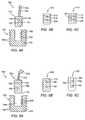
- FIGS. 17A and 17Bare cross-sectional views of embodiments of a bone anchor in an unlocked state and a locked state, respectively.
- FIGS. 18A and 18Bare cross-sectional views of embodiments of a bone anchor in an unlocked state and a locked state, respectively.
- FIGS. 19A and 19Bare cross-sectional views of an alternative embodiment of the bone anchor depicted in FIGS. 17A and 17B .
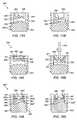
- FIGS. 20A and 20Bare, respectively, a cross-sectional view and a perspective side view of an embodiment of an unlocked state of a bone anchor that includes a bone anchor member and a plug portion.
- FIGS. 21A and 21Bare, respectively, a cross-sectional view and a perspective side view depicted in FIGS. 20A and 20B in a locked state.
- FIG. 22Ais a cross-sectional view of an embodiment of a bone anchor that includes a bone anchor member and a plug portion.
- FIG. 22Bis a cross-sectional view of the plug portion inserted in the bone anchor member depicted in FIG. 22A .
- FIG. 23Ais a cross-sectional view of an embodiment of the plug depicted in FIGS. 22A and 22B .
- FIG. 23Bis a perspective side view of the plug depicted in FIG. 23A .
- FIG. 23Cis a perspective bottom view of the plug depicted in FIG. 23A .
- FIG. 24Ais a cross-sectional view of an embodiment of a bone anchor that includes a bone anchor member and a plug portion.
- FIG. 24Bis a cross-sectional view of a plug portion inserted into the bone anchor member depicted in FIG. 24A .
- FIGS. 25A and 25Bare illustrations of the bone anchor depicted in FIGS. 24A and 24B employing two sutures.
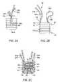
- FIG. 26Adepicts an embodiment of a bone anchor.
- FIG. 26Bis a cross-sectional view depicting a suture locking mechanism of the bone anchor depicted in FIG. 26A in a closed position.
- FIG. 26Cis a cross-sectional view depicting the suture locking mechanism depicted in FIG. 26B in an open position.
- FIG. 26Dis an exploded view of the bone anchor depicted in FIG. 26A .
- FIG. 27Ais a perspective view of an embodiment of a bone anchor.
- FIG. 27Bis a cross-sectional view of the bone anchor depicted in FIG. 27A .
- FIG. 27Cis an exploded view of the bone anchor depicted in FIG. 27A .
- FIG. 28Ais a perspective view of an embodiment of a bone anchor.
- FIGS. 28B and 28Care cross-sectional views of the bone anchor depicted in FIG. 28A with release elements in the locked and unlocked positions, respectively.
- FIG. 28Dis an exploded view of the bone anchor depicted in FIG. 28A .
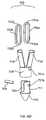
- FIG. 29Adepicts an embodiment of a bone anchor having a cam with a suture positioned between the cam and a surface at the distal end of the bone anchor.
- FIG. 29Bis a cross-sectional view of the embodiment depicted in FIG. 29A .
- FIG. 29Cis a perspective front view of the bone anchor depicted in FIG. 29A .
- FIG. 29Dis an exploded view of the bone anchor and suture depicted in FIG. 29A .
- FIG. 30Adepicts an embodiment of a bone anchor having a suture locking assembly.
- FIG. 30Bis a cross-sectional view of the bone anchor depicted in FIG. 30A .
- FIG. 30Cis a perspective side view of the bone anchor depicted in FIG. 30A .
- FIG. 30Dis an exploded view of the bone anchor depicted in FIG. 30A .
- FIG. 1is an illustrative schematic of a bone and tissue interface.
- Tissue Thas a torn end and it is desirable to secure the torn end to a section of bone B.
- hole H having diameter d Hmay be drilled in bone B, as depicted, using generally known bone drilling techniques.
- Bone anchor member 20may secure tissue T to bone B. Bone anchor member 20 may be used in conjunction with a length of suture 30 . Suture 30 has first end 32 a and second end 32 b . Ends 32 a , 32 b may be coupled to bone anchor member 20 . A central region of suture 30 forms loop 34 . Loop 34 may be threaded through a section of tissue T near the torn end of the tissue using generally known threading techniques. In embodiments described herein tissue, hole, and bone refer to T, H, and B, respectively, as described in FIG. 1 .
- FIG. 2Ais a perspective front view of an embodiment of a bone anchor.
- FIG. 2Bis a perspective side view of the bone anchor along line A-A shown in FIG. 2A .
- FIG. 2Cis a cross-sectional view of the bond anchor depicted in FIG. 2A .
- Bone anchor member 20has proximal region 22 and distal region 24 , as depicted in FIG. 2A .
- Bone anchor member 20includes a plurality of cleated members 42 .
- Cleated members 42may be formed on or attached to an exterior surface of bone anchor member 20 .
- Cleated members 42may secure bone anchor member 20 within a hole of a bone.
- bone anchor member 20may include radially expandable members. Radially expandable members may embed into bone to secure the bone anchor member to the bone.
- bone anchor member 20may include threaded exterior members. Threaded exterior members may screw into surrounding bone to secure the bone anchor member to the bone.
- bone anchor member 20includes first guide channel 50 and second guide channel 52 .
- Guide channels 50 , 52are formed within opposing surfaces of bone anchor member 20 .
- Guide channels 50 , 52are configured to accommodate regions of suture 30 , so that the suture regions do not extend outside of the confines of the guide channels when in use.
- Bone anchor member 20includes first passage 60 and second passage 70 .
- Passages 60 , 70extend laterally through a main body of bone anchor member 20 , as depicted in FIG. 2C .
- Passage 60communicates with first guide channel 50 via opening 61 , and further communicates with guide channel 52 via opening 62 .
- passage 70communicates with guide channel 50 via opening 71 , and further communicates with guide channel 52 via opening 72 .
- Passage 60is shown disposed proximal to second passage 70 , i.e., the passage 60 is closer to proximal region 22 of bone anchor member 20 .
- the passagesalso may be disposed adjacent one another, or otherwise positioned, to achieve the objects of the present invention.
- Passages 60 , 70include at least one cleated member 74 .
- Cleated member 74includes angled sections 75 and substantially orthogonal sections 76 .
- Orthogonal sections 76are disposed adjacent one another, thereby forming a cleated shape, as shown in FIG. 2C .
- Angled sections 75are angled towards opening 62 of passage 60 and opening 72 of passage 70 , as shown in FIG. 2C .
- cleated passages 60 , 70are configured to permit one-way movement of first suture end 32 a and second suture end 32 b . For example, when suture end 32 a is pulled in a proximal direction, angled sections 75 allow movement of the suture end in the proximal direction, while inhibiting distally advancement of suture end 32 a within passage 60 .
- an outer diameter of suture 30may be slightly larger than an inner diameter of cleated passages 60 and 70 . Therefore, suture ends 32 a and 32 b can pass through cleated passages 60 and 70 in a proximal direction with relatively little resistance while the suture holds significantly greater force in the distal direction.
- a method for coupling suture 30 between tissue T and bone anchor member 20a central region of suture 30 can be looped through tissue T first, such that free ends 32 a and 32 b extend from the tissue. Free end 32 a is then threaded through one-way cleated passage 60 in a proximal direction, while free end 32 b is threaded through one-way cleated passage 70 , also in a proximal direction.
- suture 30may be coupled between tissue T and bone anchor member 20 using other threading techniques, so long as the suture ultimately is situated in a manner depicted in FIG. 2C .
- First end 32 a of suture 30is disposed through first passage 60 , then transitioned into loop portion 34 a .
- Loop portion 34 atransitions into loop portion 34 b , forming loop 34 therebetween, which is coupled to tissue T.
- Loop portion 34 btransitions into second end 32 b , which is disposed through passage 70 , as shown in FIG. 2C . Accordingly, first and second ends 32 a , 32 b of suture 30 may be independently manipulated for purposes described herein below.
- bone anchor member 20is distally advanced into a hole of a bone under arthroscopic guidance. Exterior cleated members 42 of bone anchor member 20 allow the bone anchor member to be advanced distally within the bone hole when an appropriate force is applied, but exterior cleated members 42 inhibit proximal movement of bone anchor member 20 to provide a secure anchor within the bone.
- cleated passages 60 and 70may approximate the positioning of the tissue with respect to the bone.
- the use of two separate passagesallows the surgeon to tension each end of the suture independently, which is often desirable when tissue is torn irregularly.
- first and second suture ends 32 a , 32 bpermits incremental tensioning of first and second suture ends 32 a , 32 b . This allows incremental adjustment during positioning of the tissue, using tactile feedback as a guide. Once a desired tension is achieved, retraction of the suture ends is stopped, and the suture is automatically locked in place. Thus, there is no need to tie a knot.
- guide channels 50 and 52permit the retraction of suture ends 32 a , 32 b when bone anchor member 20 is secured within a hole of the bone by providing a clearance between the bone anchor member and the bone itself.
- suture 30may be coupled to bone anchor member 20 using techniques described herein below with respect to FIGS. 3A-3E or FIGS. 6-8 . These techniques allow the suture to be coupled to bone anchor member 20 without the need to thread free ends 32 a and 32 b through passages 60 and 70 .
- FIGS. 3A-3Eshows a further embodiment of bone anchor 20 ′.
- Bone anchor 20 ′includes a first mating portion 22 a and a second mating portion 22 b .
- mating portions 22 a , 22 bare substantially symmetrical, except as noted below.
- mating portion 22 aincludes cleated passage portion 60 a and cleated passage portion 70 a .
- Mating portion 22 bincludes cleated passage portion 60 b and cleated passage portion 70 b .
- cleated passage portion 60 a and cleated passage portion 60 bform cleated passage 60 ′
- cleated passage portions 70 a and cleated passage portion 70 bform cleated passage 70 ′.
- Guide channel portions 50 a of mating portion 22 a and guide channel 50 b of mating portion 22 bform guide channel 50 ′ in the assembled state as depicted in FIGS. 3A and 3C .
- Guide channel portion 52 a of mating portion 22 a and guide channel portion 52 b of mating portion 52 bform guide channel 52 ′ in the assembled state as depicted in FIG. 3D .
- Mating portion 22 aincludes at least one mating pocket 59 , as depicted in FIG. 3E .
- Mating portion 22 bincludes at least one protrusion 55 , which is configured to securely engage a corresponding pocket 59 in the assembled state of FIGS. 3A and 3C .
- protrusion 55includes ledge 57 , as shown in detail “B” of FIG. 3D .
- mating pocket 59may include a complementary recess having a slightly larger diameter (not shown), which is configured to receive ledge 57 . In this manner, ledge 57 of protrusion 55 may snap into engagement with the larger diameter recess of pocket 59 , thereby securing mating portions 22 a , 22 b.
- a first suture endmay be positioned in cleated passage portion 60 a , and a second suture end positioned in cleated passage portion 70 a of FIG. 3E .
- mating portion 22 bis secured to mating portion 22 a , (e.g., using a snap-lock engagement described above between protrusion 55 and pocket 59 ).
- the first and second suture endsare disposed through cleated passages 60 , 70 .
- threading the suture ends through cleated passages 60 and 70is not necessary, thereby increasing the speed and ease of use of the device.
- FIGS. 4A-4CAn alternate embodiment of bone anchor 100 is described in FIGS. 4A-4C .
- FIG. 4Ais a cross-sectional view of an embodiment of a bone anchor that includes bone anchor member and a plug portion.
- FIG. 4Bis a side view of the plug portion depicted in FIG. 4A .
- FIG. 4Cis a side view of an opposing side of the plug portion depicted in FIG. 4A .
- bone anchor 100includes bone anchor member 102 and plug portion 110 .
- Bone anchor member 102includes main body 103 having bore 104 disposed therein.
- Main body 103may include cleated members 106 disposed on the outer surface thereof.
- the shape and dimensions of cleated members 106is not limited to that depicted in FIG. 4A .
- cleated members 106may be shaped substantially similar to the cleated members 42 of bone anchor member 20 .
- Cleated members 106are configured to insert into a hole of a bone using a frictional force fit.
- plug portion 110may be inserted into bore 104 of bone anchor member 102 .
- Plug portion 110may include cleated members 116 on the outer surface thereof. Cleated members 116 may be configured to permit the advancement of plug portion into bore 104 and allow plug portion 110 to engage and frictionally grip inner wall 105 , thereby securing the plug portion 100 to bone anchor member 102 .
- plug portion 110includes first and second passages 118 and 120 .
- First and second suture ends 32 a and 32 bmay be coupled to plug portion 110 of apparatus 100 in a manner similar to that described in FIG. 2C .
- First end 32 a of suture 30is disposed through first passage 118 .
- first end 32 aAfter exiting through first passage 118 , first end 32 a then transitions into loop portion 34 a , forms loop 34 , and transitions into loop portion 34 b (e.g., as shown in FIGS. 2A-2C ).
- Loop portion 34 btransitions into second end 32 b , which extends through second passage 120 .
- suture 30may be coupled to plug portion 110 using techniques described hereinbelow with respect to FIGS. 6-8 . These techniques allow the suture to be coupled to plug portion 110 without the need to thread free ends 32 a and 32 b through passages 118 and 120 , as set forth below.
- passages 118 and 120 of FIGS. 4A-4Cmay include cleated members 74 , as described hereinabove with respect to FIG. 2C . If cleated members 74 are employed, then tissue may be secured to a bone (e.g., see FIG. 1 ) by individually tensioning first and second ends 32 a , 32 b of suture 30 , as described hereinabove.
- Plug portion 110preferably includes one or more guide channels 125 disposed in a lateral surface of plug body 113 .
- Guide channel 125preferably is substantially similar to guide channels 50 and 52 of FIG. 2C .
- guide channel 125is configured to permit retraction of first and second suture ends 32 a and 32 b when plug portion 110 is secured within bore 104 by providing a clearance between the plug portion and the bone anchor member.
- passages 118 and 120may be substantially smooth passages, such that cleated members 74 are not employed. In this case, passages 118 and 120 permit substantially unimpeded movement of suture 30 through the passages.
- suture ends 32 a and 32 bmay be individually tensioned prior to insertion of plug portion 110 into bone anchor member 102 .
- plug portion 110is then forced into bore 104 of bone anchor member 102 . This causes suture ends 32 a and 32 b to be sandwiched between plug portion 110 and bone anchor member 102 when guide channels 125 are not present. Accordingly, the suture is secured between the two portions using a force fit.
- FIGS. 5A-5Cshow a further embodiment of a bone anchor apparatus.
- Bone anchor 140may include bone anchor member 142 and plug portion a 150 as shown in FIG. 5A .
- FIG. 5Bis a side view of the plug portion depicted in FIG. 5A .
- FIG. 5Cis a side view of an opposing side of the plug portion depicted in FIG. 5A .
- apparatus 140includes bone anchor member 142 and plug portion 150 .
- Bone anchor member 142includes main body 143 having bore 144 disposed therein.
- Main body 143may include exterior cleated members 146 and interior cleated members 145 disposed on the inner surface of bore 144 .
- Exterior cleated members 146are configured to insert into a hole of a bone (e.g., see FIG. 1 ) using a force fit, as described in earlier embodiments above.
- Plug portion 150includes main body 153 .
- main body 153may be substantially cylindrical in shape.
- the exterior surface 156 of main body 153may be substantially smooth.
- Main body 153may include taper 157 at the distal end thereof.
- Suture 30 having first and second ends 32 a , 32 bis coupled to plug portion 150 .
- a method of couplingis described hereinbelow with respect to FIGS. 6-8 .
- bone anchor member 142is advanced into a hole of a bone (e.g., see FIG. 1 ). Exterior cleated members 146 of bone anchor member 142 permit one-way movement of the bone anchor member into the hole.
- Plug portion 150may be inserted into bore 144 of bone anchor member 142 .
- An outer diameter of exterior surface 156 of plug portion 150may be slightly larger than an inner diameter of bore 144 . Accordingly, when plug portion 150 is urged distally, a force fit is achieved to secure plug portion 150 within the bore of bone anchor member 142 .
- Taper 157 of plug portion 150facilitates the distal advancement of the plug portion with respect to bone anchor member 142 .
- Interior cleated members 145are configured to permit advancement of plug portion 110 into bore 144 in a distal direction only.
- First and second suture ends 32 a and 32 bmay be coupled to plug portion 150 in a manner described hereinabove with respect to FIGS. 4A-4C .
- first end 32 a of suture 30is disposed through first passage 158 , and forms a loop that is threaded through a tissue.
- Second end 32 b of suture 30extends through second passage 160 .
- First and second passages 158 , 160may include cleated members 74 (see FIG. 2C ). If cleated members 74 are employed, then tissue may be secured to the bone by individually tensioning first and second ends 32 a , 32 b of suture 30 . Cleated members 74 permit incremental tensioning of each suture end, and serve to lock the suture ends within their respective passages 158 and 160 , as generally set forth hereinabove with respect to FIG. 2C .
- Plug portion 150includes one or more guide channels 165 disposed in a lateral surface of plug body 153 , as shown in FIG. 5C .
- Guide channel 165is configured to permit retraction of first and second suture ends 32 a , 32 b when plug portion 150 is secured within bore 144 .
- guide channel 165is substantially similar to guide channel 50 of FIG. 2C .
- passages 158 , 160may be smooth passages, such that cleated members 74 are not employed and guide channels 165 are not present. In some embodiments, passages 158 , 160 may be substantially smooth.
- suture ends 32 a , 32 bmay be individually tensioned prior to insertion of plug portion 150 into bone anchor member 142 . When tissue is appropriately secured to the bone, then plug portion 150 is forced into bore 144 of bone anchor member 142 . This causes suture ends 32 a , 32 b to be sandwiched between plug portion 150 and bone anchor member 142 . Accordingly, the suture is secured between the two portions using a force fit.
- FIGS. 6A-6CFurther embodiments of a plug portion are described in FIGS. 6A-6C .
- the plug portionmay be used in bone anchors depicted in FIGS. 4A-4C .
- FIG. 6Ais a side view of an embodiment of plug portion in a closed state.
- FIG. 6Bis a side view of the plug portion depicted in FIG. 6A in a partially open state.
- FIG. 6Cis a top view of the plug portion depicted in FIG. 6B .
- Plug portion 110 ′includes first and second plug portions 110 a , 110 b , which are coupled together using hinge member 115 .
- Hinge member 115may be integral to first and second plug portions 110 a , 110 b , or the hinge member may be a third element that couples two distinct portions together.
- Hinge member 115permits plug portion 110 ′ to transition between a closed state, as shown in FIG. 6A , and a partially or fully open state, as depicted in FIGS. 6B-6C , respectively.
- a first suture endmay be positioned (e.g., quickly positioned by a physician) in passage 118 a and a second suture end positioned in passage 120 a .
- the positioning of the suture endsmay be reversed (e.g., first and second suture ends may be placed in passages 120 b and 1118 b , respectively).
- plug portion 110 ′may be transformed into a closed state, depicted in FIG. 6A , by rotating first and second plug portions 110 a , 110 b together.
- first and second plug portions 110 a , 110 bform first and second passages 118 ′, 120 ′.
- the apparatusmay be actuated to secure tissue to bone.
- hinge member 115serves to ensure proper alignment of first and second plug portions 110 a , 110 b in the closed state.
- a securing meanssuch as protrusion 55 and pocket 59 of FIGS. 3A-3E , may be employed to secure plug portions 110 a and 110 b .
- the securing meansmay be reversible, such that plug portions may be separated, as shown in FIGS. 6B-6C , to reposition the suture ends.
- FIG. 7depicts a perspective view of a plug in a partially opened state.
- Plug portion 110 ′′includes first and second plug portions 110 a ′, 110 b ′, which have different sizes.
- Hinge member 115is offset from the center of plug portion 110 ′′.
- passage portions 118 a ′ and 120 a ′ of plug portion 110 a ′are each less than 180 degrees.
- passage portions 118 b ′ and 120 b ′ of plug portion 110 b ′are each greater than 180 degrees.
- a first suture endmay be positioned in passage portion 118 b ′, and then a second suture end is placed in passage portion 120 b ′. Since these passage portions are each greater than 180, the suture ends may be pressed into the passage portions. Using such a method the suture ends remain at least partially in place. With the suture ends in place, plug portion 110 ′′ is transformed to a closed state. In the closed state, passage portions 118 a ′, 118 b ′ form a first one-way, 360-degree passage through which the first suture end may pass. The second passage portions 120 a ′, 120 b ′ form a second one-way, 360-degree passage through which the second suture end may pass.
- FIG. 8Ais a side view of an embodiment of a plug.
- FIG. 8Bis a side view of the plug depicted in FIG. 8A in a partially open state.
- FIG. 8Cis a top view plug depicted in FIG. 8A in a fully open state.
- Hinge member 115is located on a lateral surface of plug portion 110 ′′, as opposed to on the distal end of the plug portion, as shown in detail “D”. Like the embodiment of FIGS. 6A-6C , the embodiment of FIGS. 8A-8C facilitates coupling of the suture to the plug portion. During use, threading of the suture through passages 118 and 120 of the plug portion is not required.
- passage portions 118 a and 120 amay be larger than passage portions 118 b and 120 b , respectively, as described with respect to FIG. 7 hereinabove.
- Bone anchor member 180is similar to bone anchor member 20 of FIGS. 2A-2C , except as noted hereinbelow.
- Cleated members 182 of bone anchor member 180are similar to cleated members 42 of bone anchor member 20 , as described hereinabove, and facilitate anchoring of bone anchor member 180 within a hole of a bone.
- guide channels 190 and 192are similar to guide channels 50 and 52 of FIGS. 2A-2C .
- bone anchor member 180includes at least one adhesive delivery channel 188 , which is provided within main body 181 .
- Adhesive delivery channel 188may be formed by drilling a hole into an upper surface of main body 181 , such that the hole extends through first passage 184 and second passage 186 .
- channel 188may be formed using other known techniques.
- First and second passages 184 and 186may include cleated members 74 of FIG. 2C , thereby permitting one-way movement of suture ends 32 a and 32 b through the passages.
- passages 184 and 186may include substantially smooth inner surfaces that permit movement of suture 30 through the passages in either direction.
- an adhesivemay be delivered to adhesive delivery channel 188 .
- the delivery of an adhesive to channel 188may be facilitated using a needle-like tube (not shown) disposed within a working cannula.
- the needle-like tubehas a distal opening that may be placed in close proximity to, or within, adhesive delivery channel 188 to deliver an adhesive thereto.
- the adhesiveis allowed to flow distally through adhesive delivery channel 188 and into portions of first and second passages 184 and 186 .
- the adhesivemay contact at least a portion of suture 30 positioned in corresponding regions of first and second passages 184 and 186 , thereby locking the suture in place.
- adhesive delivery channel 188is depicted in FIG. 9
- multiple adhesive delivery channelsmay be employed to secure the suture, irrespective of whether cleated members 74 are employed.
- apparatus 200includes bone anchor member 202 and plug portion 210 .
- Apparatus 200is similar to apparatus 140 of FIGS. 5A-5C , except as noted below.
- Bone anchor member 202includes main body 203 having bore 204 disposed therein.
- Main body 203 of bone anchor member 202includes exterior cleated members 206 , which are configured to be inserted into a hole of a bone (e.g., see FIG. 1 ) using a force fit, as described hereinabove.
- Plug portion 210may be substantially cylindrical in shape and includes main body 213 .
- Main body 213has smooth exterior surface 216 and taper 217 .
- taper 217may be formed at the distal end of main body 213 .
- Suture 30 having first and second ends 32 a , 32 bis coupled to plug portion 210 , preferably in a manner described hereinabove with respect to FIGS. 6-8 .
- the outer diameter of main body 213may be sized slightly larger than an inner diameter of bore 204 .
- the size of diameteris selected to allow main body 213 of plug portion 210 to be distally advanced into bore 204 when forced.
- Taper 207 of bone anchor member 202is facilitates advancement of plug portion 210 into bore 204 .
- bone anchor member 202is secured within a hole of a bone when the bone anchor member is distally advanced into the hole, as depicted in FIG. 10B .
- Exterior cleated members 206 of bone anchor member 202permit one-way movement of the bone anchor member into the hole.
- Plug portion 210is advanced distally into bore 204 of bone anchor member 202 and secured therein using a force fit, as described hereinabove. At this time, surrounding regions of the bone may apply a compressive force upon bone anchor member 202 , as indicated by the larger directional arrows in FIG. 10B . This compressive force upon bone anchor member 202 in turn causes compression upon plug portion 210 , as indicated by the smaller directional arrows in FIG. 10B , thereby securely retaining the plug portion within bore 204 .
- passages 218 and 219may include cleated members 74 as described hereinabove with respect to FIG. 2C .
- passages 218 and 219may include substantially smooth interior surfaces that permit advancement of suture 30 in either direction.
- the position of the tissue relative to the bonemay be approximated by individually tensioning suture ends 32 a and 32 b prior to insertion of plug portion 210 into bone anchor member 202 .
- the tissue positionis approximated when passage 219 is disposed just above bore 204 .
- plug portion 210is advanced distally into bore 204 , thereby locking the suture. Specifically, the suture will be sandwiched between exterior surface 216 of plug portion 210 and inner wall 205 of bone anchor member 202 .
- apparatus 220may include a bone anchor member 222 and a plug portion 230 .
- Apparatus 220is similar to apparatus 200 of FIGS. 10A-10B , except as noted below.
- Bone anchor member 222includes main body 223 having bore 224 disposed therein, as depicted in FIG. 11 . Further, main body 223 includes exterior cleated members 226 , which are configured to be inserted into a hole of a bone (e.g., see FIG. 1 ) using a force fit, as described hereinabove. Bone anchor member 222 includes a proximal protrusion having inward taper 227 . Proximal stop 228 is formed between inward taper 227 and inner wall 225 of bone anchor member 222 .
- Plug portion 230includes main body 233 having proximal region 235 , central region 234 and tapered distal region 237 .
- Tapered distal region 237is sized to pass through taper 227 of bone anchor member 222 when a distally directed force is applied to plug portion 230 .
- central region 234 of plug portion 230is advanced into bore 224 via taper 227 .
- proximal region 235is advanced past taper 227 .
- proximal stop 228is configured to abut proximal edge 236 of plug portion 230 , thereby securing the plug portion within bone anchor member 222 .
- apparatus 220may further include any of the other features described above with respect to the embodiments of FIGS. 2-10 .
- passages 238 and 239may include cleated members 74 of FIG. 2C , or alternatively may include substantially smooth interior surfaces.
- the operation of apparatus 220preferably is substantially similar to the methods described hereinabove with respect to the embodiments of FIGS. 2-10 .
- a bone anchormay be positioned in bone throughole H T , which has two openings to the surface of the bone.
- bone anchor 240is similar to bone anchor member 20 of FIGS. 1-2 , but is configured for use in applications where through hole H T is employed.
- Bone anchor 240includes main body 242 having proximal and distal ends. Flange 245 disposed at the proximal end and taper 246 formed at the distal end of main body 242 .
- Main body 242includes exterior surface 243 disposed between flange 245 and taper 246 .
- Bone anchor 240includes first and second passages 250 and 252 , each having a plurality of cleated members 254 .
- Each of the cleated membersincludes angled sections 255 and substantially orthogonal sections 256 , which are disposed adjacent one another thereby forming a cleated shape, as described hereinabove with respect to cleated members 74 of FIG. 2C .
- a loop of suture 30may be coupled through tissue T first, with free ends 32 a and 32 b extending from the tissue. Free end 32 a then is threaded through first passage 250 in a proximal direction. Free end 32 b is threaded through second passage 252 , also in a proximal direction.
- the suturemay be threaded through passages 250 , 252 and tissue T by arthroscopically operating on one or both sides of bone B.
- suture 30may be coupled between tissue T and bone anchor 240 using other arthroscopic threading techniques, so long as the suture ultimately is situated in a manner depicted in FIG. 12 .
- first and second suture ends 32 a and 32 bmay be proximally retracted, one at a time, to approximate the position of tissue T with respect to bone B.
- flange 245which has an outer diameter larger than the diameter of through hole H T , abuts bone B. The system becomes tensioned because flange 245 and tissue T are drawn against the bone from opposing directions.
- cleated passages 250 and 252are configured to permit one-way movement of first and second suture ends 32 a and 32 b , respectively.
- first end 32 ais pulled in a proximal direction
- angled sections 255permit movement of the suture end in the proximal direction.
- suture end 32 ais inhibited from distally advancing within passage 250 .
- the use of two separate passagesallows each end of the suture to be separately tensioned, which is often desirable when tissue T is torn irregularly.
- FIG. 12may be accomplished using a separate bone anchor member and plug portion.
- the principles of the embodiments in FIGS. 4-5 and FIGS. 10-11 , in which separate bone anchor and plug portions are employed,may be implemented in lieu of one-piece bone anchor 240 .
- suture securing methods described in FIG. 12may be accomplished using substantially smooth passages 250 and 252 .
- substantially smooth passagesare employed, an interference fit or an adhesive may be employed in lieu of the cleated passages to facilitate securing of the suture.
- the interference fit or adhesivemay be used, for example, as described hereinabove with respect to the embodiments of FIGS. 4-5 and FIGS. 10-11 .
- FIG. 13Ais a cross-sectional view of an embodiment of an apparatus that includes a bone anchor member and a plug portion.
- apparatus 270includes bone anchor member 272 and plug portion 280 .
- Bone anchor member 272includes main body 273 having bore 274 disposed therein.
- Main body 273includes exterior cleated members 276 , which are configured to be inserted into a hole of a bone (e.g., see FIG. 1 ) using a force fit, as described hereinabove.
- Bone anchor member 272includes a proximal protrusion having inward taper 277 .
- Proximal stop 278is formed between inward taper 277 and an inner wall of bone anchor member 272 .
- Bone anchor member 272includes first and second spring elements 292 a and 292 b , which are disposed at a distal region of bore 274 .
- First and second spring members 292 a and 292 bmay be integrally formed with bone anchor body 273 , or may be separate elements coupled to body 273 .
- First and second spring elements 292 a and 292 bmay be deformed to accommodate plug portion 280 within bore 274 , and also to enable locking and unlocking of a suture (not shown in FIGS. 13A-13C ) used in conjunction with apparatus 270 .
- one or more spring elementsmay be employed.
- First and second passages 298 and 299extend laterally through main body 273 of bone anchor member 272 .
- First and second passages 298 and 299are configured to selectively align with first and second passages 288 and 289 of plug portion 280 , for the purposes described hereinafter.
- Plug portion 280 of apparatus 270includes main body 283 having proximal and distal ends.
- the proximal endincludes flange 284 .
- Taper 286is disposed between flange 284 and main body 283 .
- Distal taper 287is disposed at the distal end of plug portion 280 .
- Plug portion 280includes first and second passages 288 and 289 , which extend laterally through main body 283 .
- first and second passages 288 and 289include substantially smooth interior surfaces.
- FIG. 13Billustrates use of apparatus 270 .
- plug portion 280is inserted into bore 274 of bone anchor member 272 , using insertion tool 294 .
- tapered distal end 287passes through taper 277 of bone anchor member 272 .
- a central region of plug portion 280is advanced into bore 274 via taper 277 .
- the proximal region having taper 286 and flange 284is then advanced past taper 277 .
- first and second spring elements 292 a and 292 bare inclined to urge plug portion 280 in a proximal direction, to allow flange 284 to abut proximal stop 278 (see FIG. 13C ).
- first and second spring elementsmay be deformed distally (see FIG. 13B ).
- Insertion tool 294may be a rod or other substantially rigid member configured to transfer a distally directed force from a physician to plug portion 290 . In some embodiments, insertion tool 294 is engages mating slot 295 , as shown in FIG. 13B .
- first and second passages 288 and 289to become substantially aligned with first and second passages 298 and 299 of bone anchor member 27 , respectively, as shown in FIG. 13B .
- a suturemay be threaded through aligned first passages 288 and 298 .
- the suturemay be threaded through a tissue, as described hereinabove, and then threaded back through aligned second passages 289 and 299 .
- First suture end 32 aextends through first passages 288 and 298
- second suture end 32 bextends through second passages 289 and 299 .
- apparatus 270is inserted into a hole of a bone under arthroscopic guidance.
- Cleated members 276secure apparatus 270 within the hole, as described hereinabove.
- first and second suture ends 32 a and 32 bwill extend outside of the arthroscopic field of vision.
- First and second suture ends 32 a and 32 bmay be selectively tensioned to approximate the positioning of the tissue with respect to the bone when first and second passages 288 and 289 are aligned with first and second passages 298 and 299 , respectively.
- insertion tool 294urges plug portion distally to cause the passages to align, as shown in FIG. 13B .
- first and second spring elements 292 a and 292 bare inclined to bias proximally, thereby urging flange 284 of plug portion 280 against proximal stop 278 of bone anchor member 272 .
- This movement of plug portion 280 with respect to bone anchor member 272causes a misalignment between first passage 288 of plug portion 280 and first passage 298 of bone anchor member 272 . Also, a misalignment occurs between second passages 289 and 299 .
- misalignmentscause first suture end 32 a to become pinched between first passages 288 and 298 , while second suture end 32 b is pinched between second passages 289 and 299 . These misalignments lock the suture in place.
- insertion tool 294may be inserted into mating slot 295 , as shown in FIG. 13B , to urge plug portion 280 distally.
- suture ends 32 a and 32 bmay be manipulated to adjust the positioning of the tissue.
- FIG. 14is a perspective cross-sectional view of an embodiment of an apparatus that includes a bone anchor member and a plug portion.
- the apparatusis similar to the apparatus described in FIG. 13 , except as described.
- Bone anchor member 272 ′includes spring element 292 ′ disposed at a distal end of main body 273 .
- Spring element 292 ′includes a distally concave configuration having a central region 293 .
- Bone anchor member 272 ′is used in conjunction with plug portion 280 in a manner similar to that described hereinabove with respect to FIGS. 13A-13C . Specifically, after plug portion 280 is inserted into bore 274 , the provision of a further distally-directed force acting on plug portion 280 causes central region 293 of spring element 292 ′ to be deformed in a distal direction. When the central region of spring element 292 ′ is deformed distally, first and second passages 288 and 289 of plug portion 280 are substantially aligned with first and second passages 298 and 299 of bone anchor member 272 ′, respectively.
- first suture end 32 amay move substantially unimpeded through aligned first passages 288 and 298
- second suture end 32 bmay move through aligned second passages 289 and 299 , respectively, as described hereinabove with respect to FIG. 13B .
- plug portion 280When a desired positioning of tissue is achieved, the force imposed upon plug portion 280 is removed (e.g., by proximally retracting insertion tool 294 , as described in FIG. 13C ) and central region 293 of spring elements 292 ′ returns in a proximal direction to its preferred orientation. This causes flange 284 of plug portion 280 to be urged against proximal stop 278 of bone anchor member 272 ′. As described hereinabove, the movement of plug portion 280 with respect to bone anchor member 272 ′ causes a misalignment between first passages 288 and 298 , and also a misalignment between second passages 289 and 299 . These misalignments pinch suture ends 32 a and 32 b to lock the suture in place.
- FIG. 15an embodiment of an apparatus that includes a bone anchor member and a plug portion is described.
- FIG. 15Ais top view of top view of an embodiment of an apparatus that includes a bone anchor and a plug portion.
- FIG. 15Bis a cross-sectional view of the bone anchor depicted in FIG. 15A along line 15 C- 15 C.
- FIG. 15Cis top view of the bone anchor depicted in FIG. 15A in a locked state.
- Apparatus 300includes bone anchor member 302 and plug portion 310 .
- Bone anchor member 302is similar to the bone anchor members described hereinabove and includes main body 303 having plurality of cleated members 306 , which are configured to anchor plug portion 302 within a hole of a bone (e.g., see FIG. 1 ).
- Bone anchor member 302includes central bore 304 , which is configured to receive plug portion 310 .
- Plug portion 310 of apparatus 300includes main body 311 having distal region 318 and central bore 312 , as shown in FIG. 15B .
- Main body 311has an outer diameter that is slightly smaller than an inner diameter of bore 304 . Accordingly, plug portion 310 is configured for circumferential rotation within bore 304 of bone anchor member 302 .
- Bone anchor member 302includes first and second semi-circular channels 305 a and 305 b , which are formed at diametrically opposing surfaces of main body 303 , as shown in FIGS. 15A and 15B . Further, plug portion 310 includes first and second semi-circular channels 315 a and 315 b , which are formed at diametrically opposing surfaces on main body 311 , as shown in FIGS. 15A and 15B .
- Apparatus 300also includes actuation knob 321 , which is disposed on an outer surface of plug portion 310 , as shown in FIG. 15A .
- Actuation knob 321is configured to be disposed within first recess 322 of bone anchor member 302 in an unlocked state, and disposed within second recess 323 in a locked state.
- first and second semi-circular channels 305 a and 305 b of bone anchor member 302are aligned with first and second semi-circular channels 315 a and 315 b of plug portion 310 , respectively, thereby forming first and second circular channels, as shown in FIGS. 15A and 15B .
- first and second semi-circular channels 305 a and 305 b of bone anchor member 302are not aligned with corresponding channels 315 a and 315 b of plug portion 310 , as shown in FIG. 15C .
- suture 30is coupled to apparatus 300 in a manner shown in FIG. 16 .
- first suture end 32 aextends through central bore 312 of plug portion 310 .
- First suture end 32 apasses through aperture 327 in plug portion 310 (see FIG. 15B ) and transitions into loop portion 34 a .
- Loop portion 34 ais threaded through the first circular channel formed by semi-circular channels 305 a and 315 a.
- Loop portion 34 athen is threaded through a tissue and transitions into loop portion 34 b .
- Loop portion 34 bis threaded through the second circular channel formed by semi-circular channels 305 b and 315 b .
- Loop portion 34 bpasses through a second aperture 327 and transitions into second suture end 32 b .
- Second suture end 32 bextends through central bore 312 of plug portion 310 .
- first and second suture ends 32 a and 32 bmay be selectively tensioned when actuation knob 322 is disposed within first recess 322 , as shown in FIGS. 15A-15B .
- first and second semi-circular channels 305 a and 305 b of bone anchor member 302are aligned with first and second semi-circular channels 315 a and 315 b of plug portion 310 , respectively, to form the first and second circular channels through which the suture can freely pass.
- first and second ends 32 a and 32 bare individually tensioned, rounded edges 328 of plug portion 310 (see FIG. 15B ) serve to reduce the shear stresses imposed upon the suture ends as they pass through apertures 327 .
- plug portion 310is rotated with respect to bone anchor member 302 to cause actuation knob 321 to be advanced into second recess 323 .
- the rotation of plug portion 310may be achieved by inserting an actuation tool such as a hexagonal key (not shown) into mating slot 325 .
- an actuation toolsuch as a hexagonal key (not shown) into mating slot 325 .
- the positioning of tissuemay be optimized (e.g., tweaked) with respect to bone after the suture has been locked, the actuation tool may be inserted into mating slot 325 and force applied to cause knob 322 to rotate in an opposing direction into first recess 322 . As described above, this forms two fully circular channels through which the suture may be advanced or retracted to facilitate positioning of the tissue with respect to the bone.
- FIGS. 17A and 17Bdepict cross-sectional views of embodiments of a bone anchor in unlocked and locked states, respectively.
- bone anchor member 340includes main body 343 having proximal and distal regions.
- Bone anchor member 340includes a plurality of cleated members 346 , and opposing guide channels 348 and 349 .
- guide channels 348 and 349are similar to guide channels 50 and 52 of FIG. 2C .
- Bone anchor member 340includes at least one passage 352 and flexible member 350 .
- Passage 352extends laterally through main body 343 .
- Flexible member 350is disposed proximal to passage 352 .
- Flexible member 350has a relaxed configuration in which it assumes a convex shape (e.g., bowed away from passage 352 ). In the relaxed configuration, shown in FIG. 17A , there is sufficient clearance between flexible member 350 and passage 352 to permit suture 30 to move substantially unimpeded through the passage.
- first suture end 32 ais passed through passage 352 .
- the first suture endthen becomes loop portion 34 a , which is threaded through the tissue, as described hereinabove.
- Loop portion 34 aextends through the tissue to become loop portion 34 b .
- Loop portion 34 bpasses back through passage 352 and becomes second suture end 32 b .
- First and second suture ends 32 a and 32 bextend outside of the arthroscopic site and may be individually tensioned during use.
- first and second suture ends 32 a and 32 bmay be individually tensioned to approximate the positioning of the tissue with respect to the bone. During this time, no external forces are applied to flexible member 350 , thereby permitting movement of the suture within passage 352 .
- the suturemay be locked in place by apply a distally directed force upon flexible member 350 , as depicted in FIG. 17B .
- Flexible member 350preferably assumes a concave shape in which distal knob 354 is urged towards corresponding pocket 355 in bone anchor member 342 .
- the distally directed forcelocks the suture in place by pinching the suture and inhibiting its movement within passage 352 .
- any number of mechanismsmay be employed to apply a distally directed force upon flexible member 350 , and further, to lock the flexible member in the concave position depicted in FIG. 17B .
- a plugmay be inserted into bore 358 , and then wedged against flexible member 350 to hold the flexible member in place.
- bone anchor member 340may include taper 277 and proximal stop 278 (see FIG. 17A ) to allow the plug to remain in place within bore 358 . In either case, the plug serves to apply a compressive force to hold the suture in the locked state.
- the flexible membermay be “bi-stable,” such that the flexible member has only two stable states.
- the first statethe flexible member is positioned as shown in FIG. 17A .
- the flexible memberis configured to “snap” from the first state into a second state, as shown in FIG. 17B .
- the flexible memberis either provided in a locked or unlocked state.
- Means for applying a proximally-directed force to the flexible membermay be used to cause the flexible member to snap from the second state, shown in FIG. 17B , to the first state, shown in FIG. 17A , thereby unlocking the device.
- a threaded membermay be used to hold the suture in a locked state.
- threaded cap 360has exterior thread 361 , which is adapted to engage grooved interior section 371 of bore 358 ′.
- threaded cap 360includes a proximal region having mating slot 365 and a distal region having distal protrusion 362 .
- threaded cap 360In an unlocked state, threaded cap 360 is situated proximally within bore 358 ′, as shown in FIG. 18A .
- locking tool 375may be inserted into mating slot 365 and then rotated clockwise to advance threaded cap in a distal direction (e.g., in a manner similar to tightening a screw). This causes a distal region of threaded cap 360 , and distal protrusion 362 , to urge flexible member 350 distally, thereby impinging upon a suture length disposed through passage 352 . This locks the suture in place.
- locking tool 375may be rotated counterclockwise within mating slot 365 to proximally retract the threaded cap. This will remove the forces imposed upon the suture, as depicted in FIG. 18A .
- flexible member 350is omitted entirely.
- threaded cap 360may directly pinch the suture in passage 352 to lock the suture in place.
- FIGS. 19A-19Ban alternative embodiment of the bone anchor of FIGS. 17A-17B is described. Operation of bone anchor member 340 ′′ is substantially the same as that of bone anchor 340 , with the main exception that locking member 380 is provided in lieu of flexible member 350 .
- Locking member 380includes cylindrical body 381 , which is configured to be confined within recess 391 of main body 343 ′′, as shown in FIG. 19A .
- Locking member 380includes distal protrusion 382 , which is configured to extend at least partially through aperture 390 of main body 343 ′′.
- First and second support members 383 a and 383 bare disposed beneath cylindrical body 381 , and may be formed integrally with locking member 380 . As shown in FIG. 19A , the first and second support members 383 a and 383 b rest on support ledge 395 of main body 343 ′′, thereby elevating locking member 380 within recess 391 .
- Bone anchor member 340 ′′then is advanced distally into a hole of a bone (e.g., see FIG. 1 ), such that cleated members 346 anchor the device in the hole.
- first and second suture ends 32 a and 32 bmay be individually tensioned to approximate the positioning of the tissue with respect to the bone.
- the suturemay be locked in place by any number of techniques that cause first and second support members 383 a and 383 b to be lowered or eliminated, thereby lowering cylindrical body 381 within recess 391 and urging distal protrusion 382 towards corresponding pocket 355 ′′, as depicted in FIG. 19B .
- the distally directed force applied by distal protrusion 382secures the suture in place.
- first and second support members 383 a and 383 bmay be fused with support ledge 395 of main body 343 ′′.
- ultrasonic energyis delivered to a proximal surface of locking member 380 , via bore 358 ′′, using techniques that are known in the art. The provision of ultrasonic energy causes first and second support members 383 a and 383 b to fuse with support ledge 395 , thereby lowering locking device 380 and locking the suture disposed within passage 352 ′′ in place.
- FIGS. 17-19While only one passage 352 is depicted, it will be apparent to one skilled in the art that a second passage may be provided, (e.g., disposed adjacent to the first passage). If two adjacent passages 352 are provided, then the suture can be threaded through the first passage, through the tissue, and threaded back through the second passage.
- an adhesivefor example, cyanoacrylate, epoxy, bone cement and so forth, may be employed in conjunction with any of the embodiments described in FIGS. 17-19 .
- Such an adhesivemay be used in conjunction with apparatus including, but not limited to, flexible member 350 , threaded cap 360 , locking member 380 , and any associated components.
- FIGS. 20A and 20Bare, respectively, a top-sectional view and a side view of embodiments of a locked state of an apparatus that includes a bone anchor and a plug portion.
- FIGS. 21A and 21Bare, respectively, a top-sectional view and a side view depicted in FIGS. 20A-20B in a locked state.
- Apparatus 400(see FIG. 20A ) includes bone anchor member 402 and plug portion 410 .
- Bone anchor member 402includes main body 403 having cleated members 406 , which are configured to secure bone anchor member 402 in a hole of a bone, as described hereinabove. Bone anchor member 402 also includes first and second passages 408 and 412 , which extend laterally through main body 403 .
- Bone anchor member 402further includes guide channels 409 a , 409 b , 413 a and 413 b , which are disposed in exterior surfaces of main body 403 .
- the guide channelspreferably are similar to guide channels 50 and 52 of FIGS. 2A-2C , except that four guide channels are employed in the present embodiment.
- first suture end 32 apasses through guide channel 409 a , through passage 408 and through guide channel 409 b .
- the first suture endthen transitions into loop 34 , which is threaded through a tissue.
- Loop 34 of suture 30then transitions into second suture end 32 b .
- Second suture end 32 bpasses through guide channel 413 b , through passage 412 , and through guide channel 413 a . Accordingly, the suture is coupled between the tissue and apparatus 400 .
- Plug portion 410 having main body 411is configured to be disposed within a central bore of bone anchor member 402 .
- Plug portion 410includes actuation knob 422 , which is configured to be disposed in first recess 423 of bone anchor member 402 in an unlocked state, and disposed within second recess 424 in a locked state.
- plug portion 410is oriented such that main body 411 does not substantially overlap with first and second passages 408 and 412 of bone anchor member 410 .
- first and second ends 32 a and 32 b of suture 30are selectively tensioned when knob 422 is disposed within first recess 423 . This is because first and second passages 408 and 412 provide a substantially unimpeded circular channel within which the suture can pass.
- plug portion 410is rotated to cause knob 422 to be advanced into second recess 424 .
- the rotation of plug portion 410 with respect to bone anchor member 402may be achieved by inserting an actuation tool (e.g., a rectangular key) into mating slot 427 .
- an actuation toole.g., a rectangular key
- the actuation toolmay be inserted into mating slot 427 to cause knob 422 to rotate back into first recess 423 (see FIGS. 20A-20B ). This removes the compressive forces imposed upon the suture, to allow the first and second ends of the suture to be individually tensioned, thus facilitating re-positioning of the tissue.
- FIGS. 22A and 22Bare cross-sectional views of an embodiment of an apparatus that includes a bone anchor member and a plug portion.
- apparatus 440includes bone anchor member 442 and plug portion 450 .
- Bone anchor member 442includes main body 443 having cleated members 446 , which are configured to secure bone anchor member 442 in a hole of a bone (e.g., see FIG. 1 ). Further, bone anchor member 442 includes central bore 444 and circumferential protrusion 449 , which is disposed near a distal end of bore 444 .
- Plug portion 450has main body 451 having proximal and distal regions.
- the proximal regionincludes first and second guide channels 456 and 457 , which are recessed in opposing lateral surfaces of main body 451 .
- the distal region of main body 451includes circumferential recess 453 and distal taper 454 .
- Plug portion 410also has a central region having passage 448 disposed laterally therethrough.
- first suture end 32 ais passed through passage 448 .
- the first suture endthen becomes loop portion 34 a , which is threaded through a tissue.
- Loop portion 34 aextends through the tissue to become loop portion 34 b .
- Loop portion 34 bpasses back through passage 448 and becomes second suture end 32 b .
- First and second suture ends 32 a and 32 bmay be manipulated during use.
- a central region of suture 30may be threaded through the tissue, and the free ends of the suture then may be passed through passage 448 in a proximal direction to achieve the depicted position of the suture.
- bone anchor member 442is inserted into a hole of the bone before plug portion 450 is inserted into bore 444 . Once bone anchor member 442 is securely disposed within the hole, plug portion 450 is positioned slightly above bone anchor member 442 , so that passage 448 is proximal to bore 444 . At this time, first and second suture ends 32 a and 32 b may be individually tensioned to approximate the positioning of the tissue with respect to the bone (e.g., see FIG. 1 ).
- plug portion 450may be advanced distally into bore 444 of bone anchor member 442 .
- An insertion toolsuch as insertion tool 294 of FIGS. 13A-13C , may be inserted into mating slot 458 to advance plug portion 450 distally.
- the provision of a sufficient distally directed forceurges taper 454 over circumferential protrusion 449 , thereby locking the plug portion within the bone anchor member, as shown in FIG. 22B .
- first and second suture ends 32 a and 32 bare compressed within guide channel 456 , while suture loop portions 34 a and 34 b are compressed within guide channel 457 .
- Guide channels 456 and 457may be sized to ensure that the suture is completely locked in place when plug portion 450 is inserted into bore 444 (see FIG. 22A ).
- guide channels 456 and 457may be sized to permit incremental adjustments of the suture, such that applying a sufficient tension to free ends 32 a and 32 b will overcome the frictional forces between the suture, plug portion 450 and bone anchor member 442 .
- FIG. 23Ais a cross-sectional view of an embodiment of the plug depicted in FIGS. 22A and 22B .
- FIG. 23Bis a perspective side view of the plug depicted in FIG. 23A .
- FIG. 23Cis a bottom view of the plug depicted in FIG. 23A .
- plug portion 450 ′includes distal passage 466 , in lieu of passage 448 of FIGS. 22A-22B .
- Distal passage 466is formed as a slot recessed in the distal end of main body 451 .
- Distal passage 466may communicate with opposing guide channels 456 and 457 .
- first and second suture ends 32 a and 32 bare disposed within distal passage 466 .
- suture ends 32 a , 32 bcan be looped around the distal end of plug portion 450 ′, and need not be inserted by threading through central passage 448 .
- the suture endsOnce the suture ends are looped around the distal end of plug portion 450 ′ and confined within passage 466 , then the suture may be held in place while inserting plug portion 450 ′ into bone anchor member 442 .
- the plug portionis locked into place via circumferential protrusion 449 (e.g., as described in FIG. 22B ), then the suture is compressed between plug portion 450 ′ and bone anchor member 442 .
- an apparatusincludes alternative bone anchor member 442 ′′ and alternative plug portion 450 ′′.
- Bone anchor member 442 ′′ and alternative plug portion 450 ′′are similar to bone anchor member 442 and plug portion 450 of FIGS. 22A-22B , except as noted below.
- Plug portion 450 ′′includes main body 451 ′ having first suture clearance channel 456 ′ formed in a first lateral surface of the body, and second suture clearance channel 457 ′ formed in an opposing lateral surface of the body. Plug portion 450 ′′ also includes clearance recess 455 on a distal region of main body 451 ′, along with suture channel 466 ′.
- Main body 451 ′includes a plurality of cleated members 459 a , which are formed adjacent to suture channel 466 ′.
- bone anchor portion 442 ′′includes a plurality of cleated members 459 b formed in bore 444 .
- Cleated members 459 bare configured to oppose cleated members 459 a when plug portion 450 ′′ is disposed in bore 444 of bone anchor member 442 ′′, as shown in FIG. 24B .
- suture length 30 ais coupled to bone anchor member 442 ′′ by first forming loop 470 between regions 35 a and 35 b of the suture. A central portion of suture 30 a then is looped around suture channel 466 ′ of plug portion 450 ′′. At this time, proximal suture ends 33 a and 33 b are proximate clearance channel 456 ′, while suture regions 35 a and 35 b are in the vicinity of clearance channel 457 ′. Plug portion 450 ′′ then is lowered into bore 444 of bone anchor member 442 ′′, as depicted in FIG. 24B .
- distal taper 454 of plug portion 450 ′′passes over protrusion 449 of bone anchor member 442 ′′.
- protrusion 449is confined within recess 453 , as shown in FIG. 24B , to substantially inhibit movement of plug portion 450 ′′ with respect to bone anchor member 442 ′′.
- Proximal suture ends 33 a and 33 bare disposed within clearance channel 456 ′, while suture regions 35 a and 35 b are disposed within clearance channel 457 ′.
- suture loop 470may be coupled directly to a tissue, as generally set forth hereinabove. Tensioning of suture ends 33 a and 33 b may directly effect positioning of the tissue. Further, as set forth above, cleated members 459 a and 459 b may form a one-way channel that facilitates tensioning of the suture ends, and locks the suture ends in place. In some embodiments, a second suture length may be employed to anchor a tissue to a bone.
- FIGS. 25A-25Bare illustrations of the bone anchor depicted in FIGS. 24A and 24B employing two sutures.
- second suture length 30 bhas loop 471 , which is coupled directly to tissue T. Loop 471 is formed between suture portions 34 a and 34 b . Proximal to suture portions 34 a and 34 b , second suture 30 b includes proximal ends 32 a and 32 b , which are configured to be manipulated during use.
- Second suture 30 bis coupled to first suture 30 a by pulling proximal ends 32 a and 32 b through loop 470 .
- proximal suture ends 32 a and 32 b of second suture 30 balong with proximal ends 33 a and 33 b of first suture 30 a , all extend from the access cannula.
- Each of the four suture endsmay be individually tensioned during use.
- loop 470 and suture regions 35 a and 35 bare urged towards clearance channel 457 ′, as shown in FIG. 25B .
- second suture 30 balso is drawn towards the clearance channel (i.e., because proximal ends 32 a and 32 b of the second suture have been previously pulled through loop 470 ).
- bone anchor member 442 ′′, plug portion 450 ′′ and first suture 30 amay be provided in an already assembled state, as shown in FIG. 24B . These components need not be assembled during the surgical procedure.
- second suture 30 bis coupled to tissue T via loop 471 .
- this methodit is not necessary to thread proximal suture ends 32 a and 32 b through plug portion 450 ′′ or bone anchor member 442 ′′ after suture 30 b is coupled to tissue T. Rather, suture ends 32 a and 32 b are pulled through loop 470 of first suture 30 a .
- first suture 30 ais coupled to tissue T, and then proximal ends 32 a and 32 b are guided through previously provided loop 470 , thereby saving operating time and effort.
- FIG. 26Adepicts an embodiment of bone anchor 500 .
- FIG. 26Bis a cross-sectional view depicting a suture locking mechanism of the bone anchor depicted in FIG. 26B in a locked position.
- FIG. 26Cis a cross-sectional view depicting the suture locking mechanism depicted in FIG. 26B in an unlocked position.
- FIG. 26Dis an exploded view of the bone anchor of depicted in FIG. 26A .
- Bone anchor 500includes main body 502 and insert 504 .
- Main body 502has cleats 506 , which are used to secure the bone anchor 500 to bone as discussed above.
- Main body 502may have any other suitable feature to secure the anchor 500 to bone, such as an expandable portion, without departing from the scope of the invention.
- Insert 504is positioned in recess 508 in main body 502 .
- the sutureenters apparatus 500 through the proximal end of recess 508 and extends through a space between main body 502 and insert 504 .
- the suturethen passes hole 510 in insert 504 .
- Hole 510is, in some embodiments, triangular shaped to accommodate different size suture as shown in FIG. 26D .
- Insert 504is movable between the closed position of FIG. 26B and the open position of FIG. 26C .
- Recess 508has beveled surface 512 on each side facing the hole 510 in the insert 504 . The suture is captured between beveled surface 512 and upper end 514 of hole 510 when insert 504 is in the closed position of FIG. 26B .
- Insert 504may be biased toward the closed position by spring portion 516 on insert 504 .
- Spring portion 516is formed by spiral cut 518 in insert 504 .
- Insert 504also has pinned connection 520 with main body 502 near the distal end. Pin 522 extends through hole 524 in insert 504 to provide pinned connection 520 .
- spring portion 516is formed integral with insert 504 a separate spring may also be provided similar to other embodiments described herein.
- Insert 504may be moved to the unlocked position of FIG. 26C by pulling on insert manipulator 524 .
- Manipulator 524may simply be flexible tether 526 , which is pulled to move insert 504 to the unlocked position. When the procedure is completed, tether 526 may be cut and removed.
- Manipulator 524provides the user with the ability to adjust suture tension as needed. Bone anchor 500 is used in the same or similar manner as the other apparatuses described herein.
- FIG. 27Ais a perspective view of an embodiment of a bone anchor.
- FIG. 27Bis a cross-sectional view of the bone anchor depicted in FIG. 27A .
- FIG. 27Cis an exploded view of the bone anchor depicted in FIG. 27A .
- Bone anchor 530has main body 532 with cleats 531 used to secure the bone anchor to bone although any other feature may be provided to secure bone anchor 530 to bone.
- the sutureis locked with a suture lock 533 .
- Suture lock 533permits the suture to be advanced in the direction of arrow 556 , but prevents movement in the other direction.
- the sutureextends around bearing surface 534 .
- Bearing surface 534may be roller 536 although a non-rotating member may also be used.
- Roller 536is mounted within hole 538 .
- Suture lock 533has first locking portion 540 and second locking portion 542 , but may include any number of locking portions.
- the first and second locking portions 540 , 542are integrally formed as ring clip 550 .
- Ring clip 550seats within annular recess 552 in main body 532 .
- Suture locks 540 , 542include suture engaging portion 554 extending from ring clip 550 .
- Locks 540 , 542may include an integrally formed living hinge 556 .
- Living hinge 556may permit the suture engaging portion 554 to deflect inwardly when suture is pulled in the direction of arrow 556 .
- Suture lock 533permits the suture to be pulled in the direction of arrow 556 and prevents the suture from being moved in the opposite direction.
- Bone anchor 530is used in the same manner as bone anchors described herein.
- FIG. 28Ais a perspective view of an embodiment of bone anchor 560 .
- FIGS. 28B and 28Care cross-sectional views illustrating the use of a release element in conjunction with the bone anchor depicted in FIG. 28A .
- FIG. 28Dis an exploded view of the bone anchor depicted in FIG. 28A .
- Bone anchor 560is used in the same manner or similar manner as other bone anchors described herein.
- Bone anchor 560includes suture lock 564 .
- Suture lock 564allows a suture to be pulled in the direction of arrow 566 , and prevents movement in the other direction.
- Suture lock 564includes cam 568 having pinned connection 570 formed by pin 571 rotatable within hole 573 (see FIG. 28D ). The suture is locked when the suture is trapped between cam 568 and inner surface 574 of main body 572 .
- Bone anchor 560includes release element 576 for releasing suture lock 564 .
- Release element 576may be part of introducer 578 .
- Introducer 578may be used when advancing bone anchor 560 into bone.
- Release element 576extends through a channel of introducer 578 .
- Release element 576 and main body 572may be configured (e.g., threaded) to allow the release element to be rotated and advanced to a desired position (e.g., as depicted in FIG. 28B ).
- Release element 576contacts upper portion of cam 568 and pivots the cam (e.g., as depicted in FIG. 28C ). Pivoting the cam permits manipulation of the suture in one or more desired directions.
- FIG. 29Adepicts an embodiment of a bone anchor having a cam with a suture positioned between the cam and a surface at the distal end of the bone anchor.
- FIG. 29Bis a cross-sectional view of the embodiment depicted in FIG. 29A .
- FIG. 29Cis a frontal view of the bone anchor depicted in FIG. 29A .
- FIG. 29Dis an exploded view of the bone anchor and suture depicted in FIG. 29A .
- bone anchor 600 depicted in FIGS. 29A-29Dhas a substantially flattened profile, such a configuration is merely meant to be illustrative of the many alternate shapes that the presently described bone anchors may take.
- bone anchor 600may be configured to have cross sectional shapes and/or dimensions different from that depicted here, without departing from the spirit or scope of the embodiments set forth herein.
- Bone anchor 600may include main body 610 with sides 611 .
- Sides 611may form cavity 612 .
- Sides 611may entirely or at least partially enclose cavity 612 .
- the cavitymay extend distally along the entire length of the main body, or may optionally extend along only a portion of the length of the main body.
- Cavity 612extends to the proximal end of the main body to form opening 613 .
- Main body 610has inner surface 615 positioned at the distal end of end of cavity 612 .
- Inner surface 615may be formed from the main body at the time of its manufacture, or may be formed by coupling block 616 to the distal end of main body 610 (see FIG. 29D ).
- opening 613may be fully surrounded at the proximal end of main body 610 .
- side surfaces 640are coupled to main body 610 to enclose opening 613 .
- Side surfaces 640may be formed from the main body at the time of its manufacture, or may be formed by coupling retainer 645 to the proximal end of main body 610 , as depicted in FIG. 29D .
- bone anchor 600may include cam 650 pivotally positioned in cavity 612 .
- Cam 650is pivotally coupled to main body 610 using, without limitation, any suitable art-recognized means of forming a rotatable connection. (e.g., a pin).
- cam 650may be positioned in cavity 612 such that hole 651 is aligned with holes 652 on opposite sides 611 , as depicted in FIG. 29D .
- Pin 653may be inserted through the aligned holes to couple cam 650 to main body 610 . This connection enables cam 650 to rotate (e.g., pivot) about the axis of pin 653 , as shown in FIG. 29B .
- cam 650may be configured to have an irregular cross sectional shape.
- FIGS. 29A-Ddepicts an embodiment where the cross sectional shape of cam 650 is substantially ovoid (e.g., see particularly FIG. 29B and FIG. 29D ). It will apparent to a practitioner of ordinary skill in the art however, that the configuration of the cam presently described embodiment is exemplary only and serves to illustrate one of the many configurations of cams suitable for use with the subject bone anchors. It will be apparent to ordinary practitioners of the art that cams configured with any cross sectional shape may be substituted for that described herein without departing from the scope of the presently described embodiments.
- cam 650may pivot in a first direction (e.g. downward) until outer cam surface 667 comes into contact with inner surface 615 (e.g., as depicted in FIG. 29B ). After contact, further rotation of cam 650 in the first direction is blocked. Cam 650 may, however still pivot in the opposite direction (e.g. upward).
- cam 650may be configured such that cam surface 667 is biased toward inner surface 615 .
- Any suitable art-recognized meansmay be used to bias cam surface 667 toward inner surface 615 .
- methods to bias a caminclude, but are not limited to, coupling the cam to a spring bias assembly, or by forming at least a portion of cam and/or inner surface of the main body from a magnetized material.
- one or more coupling members 630may be disposed on the exterior surface of main body 610 .
- Coupling membersmay be used to secure bone anchor 600 to an opening in a bone in which the bone anchor is positioned.
- Main body 610may include any other suitable feature to secure the bone anchor 600 to bone, such as an expandable portion, without departing from the scope of the invention.
- coupling members 630may extend radially from the main body.
- coupling members 630may be configured to reversibly engage a bone surface.
- coupling membersmay be formed, at least in part, of a substantially rigid or deformable material.
- the coupling membersare formed from the main body during the time of its manufacture.
- coupling membersmay be manufactured separately and coupled to the exterior surface of the main body.
- the main bodymay be coupled to the coupling members at the in a point of care setting.
- the main bodymay be configured to fit to a variety of coupling members, each having unique features suited to particular applications. A choice of coupling members may be provided to the physician at the point of care and coupled to the main body.
- Such a systemallows the physician to choose the coupling member(s) best suited to a particular patient and application (e.g., size, depth and/or width of the bone hole), without having to interrupt and prolong the procedure underway in order to choose an alternate bone anchor and prepare it for implantation.
- the coupling of a main body to coupling membersmay be by any suitable means generally known in the art.
- a main bodymay be coupled to coupling members using a snap-locks, screws, adhesives, or any other suitable means described above or generally known in the art.
- a non-limiting exampleis depicted in FIG. 29A .
- a physicianmay choose clip 620 , which includes one or more radially extendable coupling members 630 .
- a pinned connectionmay be formed by aligning hole 623 with hole 622 and inserting pin 621 through the aligned holes, as depicted in FIG. 29D .
- Coupling members 630extend radially from main body 610 .
- a bone anchormay be positioned in an opening in a bone by first retracting the coupling members. Retraction may be accomplished using a device (e.g., an inserter) that is capable of grasping the coupling members and compressing them toward the main body. When the bone anchor is suitably positioned in the bone opening, the inserter releases coupling members, allowing them to move radially outward and engage the surface of the bone opening. Alternatively, the bone anchor may be inserted into a bone opening without retracting the coupling members, and allowing the coupling members to grip the surface of the opening in which the bone anchor is placed.
- a devicee.g., an inserter
- Suture 660may be positioned in bone anchor 600 to allow tensioning one or both ends of the suture to optimize positioning of the tissue relative to the bone.
- Suture 660includes distal loop portion 665 , which is coupled to the tissue, and suture end portions 662 a , 662 b , which are coupled to bone anchor 600 .
- suture end portions 662 a and 662 bmay be tensioned so that the tissue is drawn toward the bone anchor.
- Suture end portions 662 a , 662 bmay be coupled to bone anchor 600 by entering through opening 613 . Suture end portions 662 a , 662 b extend toward the distal end of main body 610 . To engage cam 650 , suture end portions 662 a , 662 b may be wrapped around at least a portion of outer surface of cam surface 650 . Optionally, cam 650 may be textured on at least a portion of its outer surface. The texturing may allow the cam surface to frictionally grip the suture. The sutures may be wrapped around cam 650 such that the suture contacts at least about 30%, at least about 40%, at least about 50%, at least about 60%, or at least about 70% of the outer surface of cam 650 .
- suture end portions 662 a , 662 bmay be wrapped around cam 650 in a hairpin configuration as shown in FIGS. 29A and 29B .
- the suture endsare positioned in space 666 between outer cam surface 667 and inner surface 615 . Wrapping the suture around the cam in a hairpin configuration may maximize contact between the suture length and the outer surface of the cam. Thus, traction between the cam surface and the suture length is enhanced.
- suture end portions 662 and 663may extend toward the proximal end of main body 610 and exit through opening 613 .
- side surface 640may hold suture end portions 662 and 663 in place at opening 613 (See FIG. 29B ), allowing the physician greater access to the suture and ease of manipulation of the suture during use.
- a suture pullermay facilitate threading of the suture ends through the bone anchor described above and shown in FIGS. 29A-D .
- the suture pullermay be similar in shape and size to the suture coupled to the tissue. In some embodiments, the suture puller is substantially S-shaped.
- the suture pullermay be threaded through the bone anchor in the same manner as the suture, prior to the positioning of the anchor in a bone opening.
- the distal end of the suture pullercouples to ends of the suture.
- a loop of suturemay pass through a tissue of interest.
- the end portions of the suturemay couple to the distal end of the suture puller. Pulling a proximal end of the suture puller passes the suture puller through the main body of the bone anchor and threads a portion of the suture end through the opening in the main body, around the cam, between the outer cam surface and the inner surface of the main body, and out through the opening in the cavity.
- the sutured tissueWhen the suture is coupled to tissue and appropriately threaded through bone anchor 600 , the sutured tissue may be drawn toward the bone by individually, or together, tensioning suture end portions 662 and 663 in the direction indicated by arrow 690 shown in FIG. 29B . Tensioning the suture causes cam surface 667 to move (e.g., pivot) away from inner surface 615 , allowing movement of suture end portions 662 and 663 in the direction indicated by arrow 690 . It will noted however that, due to the configuration of cam surface 667 relative to inner surface 615 , after the tension applied to suture end portions 662 and 663 is released, cam surface 667 returns to its position adjacent to inner surface 615 .
- Tension applied to suture end portions 662 and 663 in the direction indicated by arrow 695locks the suture in place by compressing end portions 662 and 663 between cam surface 667 and inner surface 615 .
- movement of a tissue coupled to a sutureis allowed only in a desired direction, while slippage or movement of the tissue back to its original position is substantially prevented.
- FIGS. 30A-Ddescribe bone anchor 700 .
- FIG. 30Adepicts an embodiment of the bone anchor having a suture locking assembly.
- FIG. 30Bis a cross-sectional view of the bone anchor depicted in FIG. 30A .
- FIG. 30Cis a side view of the bone anchor depicted in FIG. 30A .
- FIG. 30Dis an exploded view of the bone anchor depicted in FIG. 30A .
- Bone anchor 700includes insert 710 and main body 715 .
- Insert 710includes one or more (e.g., a plurality) of flange members 711 (see FIG. 30D ).
- Flange members 711may extend proximally from insert 710 .
- Cavity 720is formed between flange members 711 . Distal end of cavity 720 includes inner surface 719 (see FIG. 30B ).
- main body 715may be configured to couple to insert 710 .
- main body 715is configured to accept and encircle flange members 711 and cavity 720 .
- Main body 715may couple to insert 710 by aligning hole 701 a in main body 715 with holes 701 b in flange members 711 (see FIG. 30D ). Pin 705 may then be inserted though the aligned holes.
- Any alternate configurations of insert 710 and main body 715 that allow coupling thereofare possible and their means of coupling, without departing from the spirit and scope of the embodiments provided herein may be used.
- Main body 715may optionally include a plurality of radial coupling members 716 .
- Radial coupling members 716may secure bone anchor 700 to bone as described herein.
- Main body 700may employ any art-recognized means for securing the anchor 700 to bone including, but not limited to, cleats.
- Bone anchor 700may also include locking assembly 740 .
- Locking assembly 740includes a plurality of locking elements 750 .
- locking elements 750are depicted as locking rings 750 a and 750 b .
- Locking rings 750 a and 750 binclude upper bar 751 a and 751 b and lower bar 752 a and 752 b , respectively.
- Locking rings 750 a and 750 bare sized to allow, when the locking rings are positioned parallel to each other, lower bars 752 a and 752 b to enter cavity 720 as depicted in FIG. 30B .
- Locking rings 750 a and 750 bmay be positioned parallel to each other when lower bars 752 a and 752 b are disposed in cavity 720 . In some embodiments, the locking rings are substantially parallel to each other. Lower bars 750 a and 750 b may be individually disposed at various positions or at the same position relative to inner surface 719 of cavity 720 . In FIG. 30B , lower bar 752 b is positioned adjacent to or in contact with inner surface 719 . In some embodiments, lower bar 752 a is positioned substantially adjacent to or in direct contact with inner surface 719 . In contrast, lower bar 752 a is positioned along the longitudinal axis of cavity 720 , at a distance farther from inner surface 719 than lower bar 752 b .
- upper bar 751 bis closer to the opening of cavity 720 than upper bar 751 a .
- Suture gap 760lies between upper bars 751 a and 751 b and is sized to accommodate the thickness of a suture.
- the locking assembly described abovemay be referred to in some embodiments as a “two bar locking assembly.”
- one or more of locking elements 750may be axially movable in cavity 720 .
- Moving locking element 750 in an axial directionmay, in some embodiments, allow the locking elements to interact with each other to either lock or release a suture length positioned in gap 760 by compressing the suture length between upper bars 751 a and 751 b .
- locking element 750may be moved axially after desired positioning of a sutured tissue (e.g., after fine-tuning placement of the tissue), in order to reversibly lock the suture in place.
- Axial movement of locking elements 750may be accomplished using any art-recognized means, including those described in detail above.
- Suture 780is positioned in bone anchor 700 to allow optimal positioning of a tissue relative to the bone by individually tensioning the ends of the suture, while substantially inhibiting movement of the suture and tissue coupled thereto in the opposite direction.
- suture 780is configured to have a distal loop portion 785 and proximal suture end portions 781 a and 781 b .
- Distal loop portion 785couples to tissue.
- Suture end portions 781 a and 781 bmay be treaded through the locking assembly of bone anchor 700 , and when tensioned in the direction indicated by arrow 790 , draw the tissue toward the bone anchor.
- suture end portions 781 a and 781 bmay be threaded through a two bar locking assembly as depicted in FIGS. 30A and 30B .
- Loop portion 785is positioned distally to bone anchor 700 , at the tissue.
- Suture end portions 781 a and 781 bmay couple to locking assembly 740 by passing the suture end portions through the opening of ring 750 a and under upper bar 751 b . Suture end portions 781 a and 781 b are wrapped upward around upper bar 751 b , passed though suture gap 760 and wrapped upward around upper bar 751 a . Suture end portions 781 a and 781 b are then available for facilitation of positioning of the sutured tissue (see FIG. 30B ).
- a suture pullermay facilitate threading of the suture ends through the two bar locking assembly as described above.
- the suture pullermay be similar in shape and size to the suture coupled to the tissue, and may be threaded through the bone anchor in the same manner as the suture, prior to the positioning of the anchor in a bone opening.
- the distal end of the suture pullercouples to suture end portions 781 a and 781 b .
- a loop of suturepasses through a tissue.
- the end portions of the sutureare coupled to the distal end of the suture puller.
- Pulling the proximal end of the suture puller in a desired directionpasses the suture puller through the locking assembly and threads suture end portions 781 a and 781 b through ring 750 a , under and around upper bar 751 b , passed though suture gap 760 and finally wrapped around upper bar 751 a.
- the sutured tissueWhen the suture is coupled to tissue and appropriately threaded through the locking assembly of the bone anchor, the sutured tissue may be drawn toward the bone by individually or together tensioning suture end portions 781 a and 781 b in the direction indicated by arrow 790 shown in FIG. 30B . Tensioning the suture ends thus allows the threaded suture to move through the locking assembly in direction 790 , thus drawing tissue toward the bone. It will noted however that, due to the configuration of the two bar locking assembly relative to the threaded suture, movement or slippage of the tissue in an opposite direction is substantially inhibited.
- Bone anchor 600described certain embodiments where the main body is configured to be used with a variety of different coupling members, each having features suited to particular applications. It will be readily appreciated by ordinary practitioners of the art however, that this feature is not limited to the embodiments of bone anchor 600 . Neither is this feature meant to be limited to the coupling of an internal portion to an external portion. In the contrary, components of the bone anchor assemblies described above are designed with the feature of modularity in mind. The ability to mix-and-match different features of an internal portion of a bone anchor assembly with a wide variety of features of external portions of the bone anchor is intended to be applied, without limitation, to all the embodiments described herein.
- Incorporating the feature of modularity into the bone anchor assembly design parametersprovides the following advantages: (a) maximized versatility in surgical applications without having to redesign bone anchor suited to such applications; (b) maintaining flexibility of the surgical procedure at the point-of-care; (c) full interchangeability of any component with any other component; (d) adjustability of each bone anchor component independent of the choice or position of other bone anchor components being used in a single surgical application; (e) allows the surgeon to tailor the assembly to the individual anatomy of the patient even in the face of a revision of the surgical procedure that might otherwise damage the bone or tissue; and (f) the use of all styles and sizes of interior and exterior components.
- the feature of modularityallows the physician to dedicate his or her full attention the procedure at hand, improving the prognosis and healing of the patient.
- Securing a bone anchor member within a hole of a bonemay be employed as previously described or using generally known bone securing techniques.
- cleated members 42 of FIG. 2Amay be used means for securing the bone anchors.
- Other alternative means for securingmay be used in conjunction with the apparatus and methods of the present invention.
- the bone anchor membermay employ one or more radially expandable members that extend into the surrounding bone.
- suture endsmay be tensioned either before or after the plug portion is inserted into the bore of the bone anchor member.
- the plug portionmay be securely disposed within the bore of the bone anchor member using various means not specifically disclosed herein.
- an adhesivefor example, cyanoacrylate, epoxy, bone cement and so forth, may be delivered to affix the plug portion to the bone anchor member.
- an exterior surface of the plug portionmay be coated with a biocompatible adhesive that affixes to the bone anchor member after the plug portion is inserted into the bore of the bone anchor member.
- heatmay be applied to fuse the plug portion to the bone anchor member. It will be apparent to one skilled in the art that still further means for securing the plug portion to the bone anchor member may be employed.
- multiple bone anchor membersor multiple bone anchor members coupled to respective plug portions may be used.
- One or more suturesmay be coupled between a desired tissue region and the bone anchor member or plug portion. If multiple sutures and bone anchor members are employed, enhanced sequential tensioning of the tissue may be achieved.
Landscapes
- Health & Medical Sciences (AREA)
- Surgery (AREA)
- Life Sciences & Earth Sciences (AREA)
- Medical Informatics (AREA)
- Nuclear Medicine, Radiotherapy & Molecular Imaging (AREA)
- Engineering & Computer Science (AREA)
- Biomedical Technology (AREA)
- Heart & Thoracic Surgery (AREA)
- Rheumatology (AREA)
- Molecular Biology (AREA)
- Animal Behavior & Ethology (AREA)
- General Health & Medical Sciences (AREA)
- Public Health (AREA)
- Veterinary Medicine (AREA)
- Surgical Instruments (AREA)
- Prostheses (AREA)
Abstract
Description
Claims (27)
Priority Applications (18)
| Application Number | Priority Date | Filing Date | Title |
|---|---|---|---|
| US11/325,252US7938847B2 (en) | 2006-01-04 | 2006-01-04 | Ring cinch assembly to attach bone to tissue |
| US11/325,619US20060282081A1 (en) | 2004-04-16 | 2006-01-04 | Apparatus and method for securing tissue to bone with a suture |
| US11/337,966US20070156176A1 (en) | 2006-01-04 | 2006-01-23 | Ring cinch assembly to attach bone to tissue |
| US11/337,933US20060282082A1 (en) | 2004-04-16 | 2006-01-23 | Apparatus and method for securing tissue to bone with a suture |
| US11/337,819US20070156149A1 (en) | 2006-01-04 | 2006-01-23 | Ring cinch assembly to attach bone to tissue |
| US11/337,939US20060282083A1 (en) | 2004-04-16 | 2006-01-23 | Apparatus and method for securing tissue to bone with a suture |
| US11/337,934US20070156150A1 (en) | 2006-01-04 | 2006-08-14 | Ring cinch assembly to attach bone to tissue |
| AU2007203780AAU2007203780B2 (en) | 2006-01-04 | 2007-01-04 | Ring cinch assembly for attaching tissue to bone with a suture |
| EP07701202AEP1986552B1 (en) | 2006-01-04 | 2007-01-04 | Ring cinch assembly for attaching tissue to bone with a suture |
| CA2636001ACA2636001C (en) | 2006-01-04 | 2007-01-04 | Ring cinch assembly to attach bone to tissue |
| CN2007800076545ACN101394795B (en) | 2006-01-04 | 2007-01-04 | Ring lock assembly for attaching tissue to bone with a suture |
| EP07701201AEP1971274A1 (en) | 2006-01-04 | 2007-01-04 | Apparatus and method for securing tissue to bone with a suture |
| PCT/US2007/060099WO2007079493A2 (en) | 2006-01-04 | 2007-01-04 | Ring cinch assembly for attaching tissue to bone with a suture |
| DE602007007188TDE602007007188D1 (en) | 2006-01-04 | 2007-01-04 | RING BELT ASSEMBLY FOR FIXING TISSUE TO BONE WITH A SEAM |
| PCT/US2007/060098WO2007079492A1 (en) | 2006-01-04 | 2007-01-04 | Apparatus and method for securing tissue to bone with a suture |
| JP2008549637AJP5211273B2 (en) | 2006-01-04 | 2007-01-04 | System for fixing tissue to bone |
| AT07701202TATE471113T1 (en) | 2006-01-04 | 2007-01-04 | RING STRAP ARRANGEMENT FOR ATTACHING TISSUE TO BONE WITH A SUTURE |
| US13/073,342US20110238113A1 (en) | 2006-01-04 | 2011-03-28 | Ring cinch assembly to attach bone to tissue |
Applications Claiming Priority (2)
| Application Number | Priority Date | Filing Date | Title |
|---|---|---|---|
| US11/325,252US7938847B2 (en) | 2006-01-04 | 2006-01-04 | Ring cinch assembly to attach bone to tissue |
| US11/325,619US20060282081A1 (en) | 2004-04-16 | 2006-01-04 | Apparatus and method for securing tissue to bone with a suture |
Related Child Applications (4)
| Application Number | Title | Priority Date | Filing Date |
|---|---|---|---|
| US11/337,819ContinuationUS20070156149A1 (en) | 2006-01-04 | 2006-01-23 | Ring cinch assembly to attach bone to tissue |
| US11/337,966ContinuationUS20070156176A1 (en) | 2006-01-04 | 2006-01-23 | Ring cinch assembly to attach bone to tissue |
| US11/337,934ContinuationUS20070156150A1 (en) | 2006-01-04 | 2006-08-14 | Ring cinch assembly to attach bone to tissue |
| US13/073,342ContinuationUS20110238113A1 (en) | 2006-01-04 | 2011-03-28 | Ring cinch assembly to attach bone to tissue |
Publications (2)
| Publication Number | Publication Date |
|---|---|
| US20070156148A1 US20070156148A1 (en) | 2007-07-05 |
| US7938847B2true US7938847B2 (en) | 2011-05-10 |
Family
ID=39721908
Family Applications (8)
| Application Number | Title | Priority Date | Filing Date |
|---|---|---|---|
| US11/325,252Active2027-07-01US7938847B2 (en) | 2004-04-16 | 2006-01-04 | Ring cinch assembly to attach bone to tissue |
| US11/325,619AbandonedUS20060282081A1 (en) | 2004-04-16 | 2006-01-04 | Apparatus and method for securing tissue to bone with a suture |
| US11/337,966AbandonedUS20070156176A1 (en) | 2006-01-04 | 2006-01-23 | Ring cinch assembly to attach bone to tissue |
| US11/337,819AbandonedUS20070156149A1 (en) | 2006-01-04 | 2006-01-23 | Ring cinch assembly to attach bone to tissue |
| US11/337,939AbandonedUS20060282083A1 (en) | 2004-04-16 | 2006-01-23 | Apparatus and method for securing tissue to bone with a suture |
| US11/337,933AbandonedUS20060282082A1 (en) | 2004-04-16 | 2006-01-23 | Apparatus and method for securing tissue to bone with a suture |
| US11/337,934AbandonedUS20070156150A1 (en) | 2006-01-04 | 2006-08-14 | Ring cinch assembly to attach bone to tissue |
| US13/073,342AbandonedUS20110238113A1 (en) | 2006-01-04 | 2011-03-28 | Ring cinch assembly to attach bone to tissue |
Family Applications After (7)
| Application Number | Title | Priority Date | Filing Date |
|---|---|---|---|
| US11/325,619AbandonedUS20060282081A1 (en) | 2004-04-16 | 2006-01-04 | Apparatus and method for securing tissue to bone with a suture |
| US11/337,966AbandonedUS20070156176A1 (en) | 2006-01-04 | 2006-01-23 | Ring cinch assembly to attach bone to tissue |
| US11/337,819AbandonedUS20070156149A1 (en) | 2006-01-04 | 2006-01-23 | Ring cinch assembly to attach bone to tissue |
| US11/337,939AbandonedUS20060282083A1 (en) | 2004-04-16 | 2006-01-23 | Apparatus and method for securing tissue to bone with a suture |
| US11/337,933AbandonedUS20060282082A1 (en) | 2004-04-16 | 2006-01-23 | Apparatus and method for securing tissue to bone with a suture |
| US11/337,934AbandonedUS20070156150A1 (en) | 2006-01-04 | 2006-08-14 | Ring cinch assembly to attach bone to tissue |
| US13/073,342AbandonedUS20110238113A1 (en) | 2006-01-04 | 2011-03-28 | Ring cinch assembly to attach bone to tissue |
Country Status (9)
| Country | Link |
|---|---|
| US (8) | US7938847B2 (en) |
| EP (2) | EP1971274A1 (en) |
| JP (1) | JP5211273B2 (en) |
| CN (1) | CN101394795B (en) |
| AT (1) | ATE471113T1 (en) |
| AU (1) | AU2007203780B2 (en) |
| CA (1) | CA2636001C (en) |
| DE (1) | DE602007007188D1 (en) |
| WO (2) | WO2007079492A1 (en) |
Cited By (128)
| Publication number | Priority date | Publication date | Assignee | Title |
|---|---|---|---|---|
| US20080077161A1 (en)* | 2006-07-20 | 2008-03-27 | Kaplan Lee D | Surgical instruments |
| US20080249567A1 (en)* | 2006-07-20 | 2008-10-09 | Kaplan Lee D | Surgical instruments |
| US20100016869A1 (en)* | 2008-07-17 | 2010-01-21 | Smith & Nephew, Inc. | Surgical Devices |
| US20100191247A1 (en)* | 2009-01-23 | 2010-07-29 | David James Schneider | Apparatus and method for arthroscopic transhumeral rotator cuff repair |
| US20100292756A1 (en)* | 2009-05-12 | 2010-11-18 | Schneider David J | Bioelectric implant and method |
| US20110087067A1 (en)* | 2009-10-09 | 2011-04-14 | Tyco Healthcare Group Lp | Internal retractor systems |
| US20110098727A1 (en)* | 2006-09-29 | 2011-04-28 | Biomet Sports Medicine, Llc | Method and Apparatus for Securing Soft Tissue to Bone |
| US20110106153A1 (en)* | 2006-02-03 | 2011-05-05 | Biomet Sports Medicine, Llc | Method and Apparatus for Sternal Closure |
| US20110238113A1 (en)* | 2006-01-04 | 2011-09-29 | Tornier, Inc. | Ring cinch assembly to attach bone to tissue |
| US20120065731A1 (en)* | 2009-07-02 | 2012-03-15 | Medicinelodge, Inc. Dba Imds Co-Innovation | Systems and methods for intra-operative tension and fixation of zipknot acl fixation |
| US20120089193A1 (en)* | 2006-09-29 | 2012-04-12 | Biomet Sports Medicine, Llc | Fracture Fixation Device |
| EP2567673A1 (en) | 2011-09-12 | 2013-03-13 | Tornier, Inc. | Verstärkungsband für die Restaurierung eines weichen Gewebes |
| US20130096611A1 (en)* | 2011-09-22 | 2013-04-18 | Derek C. Sullivan | Tensionable knotless anchors with splice and methods of tissue repair |
| US20130123842A1 (en)* | 2011-11-16 | 2013-05-16 | VentureMD Innovations, LLC | Suture anchor |
| US20130197579A1 (en)* | 2012-01-27 | 2013-08-01 | Seth A. Foerster | Method for soft tissue repair with free floating suture locking member |
| US20130197576A1 (en)* | 2012-01-27 | 2013-08-01 | Pablo Catania | Free floating wedge suture anchor for soft tissue repair |
| US8500818B2 (en) | 2006-09-29 | 2013-08-06 | Biomet Manufacturing, Llc | Knee prosthesis assembly with ligament link |
| US8506597B2 (en) | 2011-10-25 | 2013-08-13 | Biomet Sports Medicine, Llc | Method and apparatus for interosseous membrane reconstruction |
| US20130211451A1 (en)* | 2012-02-09 | 2013-08-15 | Anulex Technologies, Inc. | Bone anchor and related instrumentation and methods |
| US8551140B2 (en) | 2004-11-05 | 2013-10-08 | Biomet Sports Medicine, Llc | Method and apparatus for coupling soft tissue to bone |
| US8562645B2 (en) | 2006-09-29 | 2013-10-22 | Biomet Sports Medicine, Llc | Method and apparatus for forming a self-locking adjustable loop |
| US8574235B2 (en) | 2006-02-03 | 2013-11-05 | Biomet Sports Medicine, Llc | Method for trochanteric reattachment |
| US8608777B2 (en) | 2006-02-03 | 2013-12-17 | Biomet Sports Medicine | Method and apparatus for coupling soft tissue to a bone |
| US8632569B2 (en) | 2006-02-03 | 2014-01-21 | Biomet Sports Medicine, Llc | Soft tissue repair device and associated methods |
| US8652172B2 (en) | 2006-02-03 | 2014-02-18 | Biomet Sports Medicine, Llc | Flexible anchors for tissue fixation |
| US8672968B2 (en) | 2006-09-29 | 2014-03-18 | Biomet Sports Medicine, Llc | Method for implanting soft tissue |
| US8771352B2 (en) | 2011-05-17 | 2014-07-08 | Biomet Sports Medicine, Llc | Method and apparatus for tibial fixation of an ACL graft |
| US8777956B2 (en) | 2006-08-16 | 2014-07-15 | Biomet Sports Medicine, Llc | Chondral defect repair |
| US8801783B2 (en) | 2006-09-29 | 2014-08-12 | Biomet Sports Medicine, Llc | Prosthetic ligament system for knee joint |
| US8840645B2 (en) | 2004-11-05 | 2014-09-23 | Biomet Sports Medicine, Llc | Method and apparatus for coupling soft tissue to a bone |
| US20140288595A1 (en)* | 2013-03-20 | 2014-09-25 | Rajiv D. Pandya | Soft tissue interference fit anchor system |
| US8900314B2 (en) | 2009-05-28 | 2014-12-02 | Biomet Manufacturing, Llc | Method of implanting a prosthetic knee joint assembly |
| US8918931B1 (en)* | 2011-02-23 | 2014-12-30 | SimpleIdeas, LLC | Bed accessory |
| US8932331B2 (en) | 2006-02-03 | 2015-01-13 | Biomet Sports Medicine, Llc | Method and apparatus for coupling soft tissue to bone |
| US8936621B2 (en) | 2006-02-03 | 2015-01-20 | Biomet Sports Medicine, Llc | Method and apparatus for forming a self-locking adjustable loop |
| US8968364B2 (en) | 2006-02-03 | 2015-03-03 | Biomet Sports Medicine, Llc | Method and apparatus for fixation of an ACL graft |
| US8998949B2 (en) | 2004-11-09 | 2015-04-07 | Biomet Sports Medicine, Llc | Soft tissue conduit device |
| US9017381B2 (en) | 2007-04-10 | 2015-04-28 | Biomet Sports Medicine, Llc | Adjustable knotless loops |
| US9078644B2 (en) | 2006-09-29 | 2015-07-14 | Biomet Sports Medicine, Llc | Fracture fixation device |
| US9101355B2 (en) | 2009-07-17 | 2015-08-11 | Pivot Medical, Inc. | Method and apparatus for re-attaching the labrum to the acetabulum, including the provision and use of a novel suture anchor system |
| US9149267B2 (en) | 2006-02-03 | 2015-10-06 | Biomet Sports Medicine, Llc | Method and apparatus for coupling soft tissue to a bone |
| US9149268B2 (en) | 2009-07-17 | 2015-10-06 | Pivot Medical, Inc. | Method and apparatus for attaching tissue to bone, including the provision and use of a novel knotless suture anchor system |
| US9173651B2 (en) | 2006-02-03 | 2015-11-03 | Biomet Sports Medicine, Llc | Soft tissue repair device and associated methods |
| US9179905B2 (en) | 2009-07-17 | 2015-11-10 | Pivot Medical, Inc. | Method and apparatus for re-attaching the labrum to the acetabulum, including the provision and use of a novel suture anchor system |
| US9198649B2 (en) | 2012-01-27 | 2015-12-01 | Arthrocare Corporation | Rotating locking member suture anchor and method for soft tissue repair |
| US9226742B2 (en) | 2012-01-27 | 2016-01-05 | Arthrocare Corporation | Restricted wedge suture anchor and method for soft tissue repair |
| US9265498B2 (en) | 2003-06-11 | 2016-02-23 | Imds Llc | Compact line locks and methods |
| US9271713B2 (en) | 2006-02-03 | 2016-03-01 | Biomet Sports Medicine, Llc | Method and apparatus for tensioning a suture |
| US9314241B2 (en) | 2011-11-10 | 2016-04-19 | Biomet Sports Medicine, Llc | Apparatus for coupling soft tissue to a bone |
| US9345467B2 (en) | 2007-10-25 | 2016-05-24 | Smith & Nephew, Inc. | Anchor assembly |
| US9357991B2 (en) | 2011-11-03 | 2016-06-07 | Biomet Sports Medicine, Llc | Method and apparatus for stitching tendons |
| US9364210B2 (en) | 2012-01-27 | 2016-06-14 | Arthrocare Corporation | Biased wedge suture anchor and method for soft tissue repair |
| US9370350B2 (en) | 2011-11-10 | 2016-06-21 | Biomet Sports Medicine, Llc | Apparatus for coupling soft tissue to a bone |
| US9381013B2 (en) | 2011-11-10 | 2016-07-05 | Biomet Sports Medicine, Llc | Method for coupling soft tissue to a bone |
| US9402621B2 (en) | 2006-02-03 | 2016-08-02 | Biomet Sports Medicine, LLC. | Method for tissue fixation |
| US9414833B2 (en) | 2006-02-03 | 2016-08-16 | Biomet Sports Medicine, Llc | Soft tissue repair assembly and associated method |
| US9445805B2 (en) | 2009-11-16 | 2016-09-20 | Tornier, Inc. | Bone implant with convertible suture attachment |
| US9492158B2 (en) | 2006-02-03 | 2016-11-15 | Biomet Sports Medicine, Llc | Method and apparatus for coupling soft tissue to a bone |
| US9504460B2 (en) | 2004-11-05 | 2016-11-29 | Biomet Sports Medicine, LLC. | Soft tissue repair device and method |
| US9538998B2 (en) | 2006-02-03 | 2017-01-10 | Biomet Sports Medicine, Llc | Method and apparatus for fracture fixation |
| US9539001B2 (en) | 2006-03-22 | 2017-01-10 | Tornier, Inc. | Bone anchor installer and method of use |
| US9572655B2 (en) | 2004-11-05 | 2017-02-21 | Biomet Sports Medicine, Llc | Method and apparatus for coupling soft tissue to a bone |
| US9615822B2 (en) | 2014-05-30 | 2017-04-11 | Biomet Sports Medicine, Llc | Insertion tools and method for soft anchor |
| US9636101B2 (en) | 2011-09-01 | 2017-05-02 | Arthrocare Corporation | Bone anchor having an integrated stress isolator |
| US9662103B2 (en) | 2010-09-23 | 2017-05-30 | Tornier, Inc. | Systems and methods for bone anchor inserter depth indication |
| US9681960B2 (en) | 2014-05-16 | 2017-06-20 | Howmedica Osteonics Corp. | Guides for fracture system |
| US9687221B2 (en) | 2013-02-13 | 2017-06-27 | Venture MD Innovations, LLC | Method of anchoring a suture |
| US9700291B2 (en) | 2014-06-03 | 2017-07-11 | Biomet Sports Medicine, Llc | Capsule retractor |
| US9737294B2 (en) | 2013-01-28 | 2017-08-22 | Cartiva, Inc. | Method and system for orthopedic repair |
| US9757119B2 (en) | 2013-03-08 | 2017-09-12 | Biomet Sports Medicine, Llc | Visual aid for identifying suture limbs arthroscopically |
| US9763656B2 (en) | 2006-02-03 | 2017-09-19 | Biomet Sports Medicine, Llc | Method and apparatus for soft tissue fixation |
| US9782165B2 (en) | 2011-11-11 | 2017-10-10 | VentureMD Innovations, LLC | Transosseous attachment |
| US9801708B2 (en) | 2004-11-05 | 2017-10-31 | Biomet Sports Medicine, Llc | Method and apparatus for coupling soft tissue to a bone |
| US9826973B2 (en) | 2009-07-17 | 2017-11-28 | Pivot Medical, Inc. | Method and apparatus for attaching tissue to bone, including the provision and use of a novel knotless suture anchor system |
| US9855028B2 (en) | 2012-04-06 | 2018-01-02 | Arthrocare Corporation | Multi-suture knotless anchor for attaching tissue to bone and related method |
| US9918826B2 (en) | 2006-09-29 | 2018-03-20 | Biomet Sports Medicine, Llc | Scaffold for spring ligament repair |
| US9918827B2 (en) | 2013-03-14 | 2018-03-20 | Biomet Sports Medicine, Llc | Scaffold for spring ligament repair |
| US9924935B2 (en) | 2015-10-23 | 2018-03-27 | Smith & Nephew, Inc. | Suture anchor assembly with slip fit tip |
| US20180092637A1 (en)* | 2008-03-18 | 2018-04-05 | Zimmer, Inc. | Knotless dynamic suture tensioning device and methods |
| US9936939B2 (en) | 2009-11-10 | 2018-04-10 | Smith & Nephew, Inc. | Tissue repair devices |
| US9955980B2 (en) | 2015-02-24 | 2018-05-01 | Biomet Sports Medicine, Llc | Anatomic soft tissue repair |
| US9962174B2 (en) | 2015-07-17 | 2018-05-08 | Kator, Llc | Transosseous method |
| US10016192B2 (en) | 2013-06-14 | 2018-07-10 | Tornier, Inc. | Suture for connecting a human or animal tissue, soft anchor and method for attaching a tissue to a bone |
| USD824441S1 (en) | 2016-03-04 | 2018-07-31 | Oc10, Llc | Cartridge |
| US10039543B2 (en) | 2014-08-22 | 2018-08-07 | Biomet Sports Medicine, Llc | Non-sliding soft anchor |
| US10058319B2 (en) | 2009-07-17 | 2018-08-28 | Pivot Medical, Inc. | Method and apparatus for attaching tissue to bone, including the provision and use of a novel knotless suture anchor system, including a novel locking element |
| US10076322B1 (en) | 2018-01-11 | 2018-09-18 | Arthrex, Inc. | Tissue button |
| USD828860S1 (en) | 2016-03-04 | 2018-09-18 | Oc10, Llc | Hand-held device |
| US10130377B2 (en) | 2016-02-08 | 2018-11-20 | Crossroads Extremity Systems, Llc | Plantar plate repair |
| US10136884B2 (en) | 2009-07-17 | 2018-11-27 | Pivot Medical, Inc. | Method and apparatus for attaching tissue to bone, including the provision and use of a novel knotless suture anchor system, including a retractable sheath |
| US10136886B2 (en) | 2013-12-20 | 2018-11-27 | Biomet Sports Medicine, Llc | Knotless soft tissue devices and techniques |
| US10143462B2 (en) | 2015-08-04 | 2018-12-04 | Kator, Llc | Transosseous suture anchor method |
| US10154868B2 (en) | 2015-07-17 | 2018-12-18 | Kator, Llc | Transosseous method |
| US10179012B2 (en) | 2013-01-28 | 2019-01-15 | Cartiva, Inc. | Systems and methods for orthopedic repair |
| US10232561B2 (en) | 2012-09-18 | 2019-03-19 | Oc10, Llc | Materials, methods and devices for joining lines |
| US10238379B2 (en) | 2009-07-17 | 2019-03-26 | Pivot Medical, Inc. | Method and apparatus for attaching tissue to bone, including the provision and use of a novel knotless suture anchor system |
| US10265060B2 (en) | 2015-08-20 | 2019-04-23 | Arthrex, Inc. | Tensionable constructs with multi-limb locking mechanism through single splice and methods of tissue repair |
| US10278692B2 (en) | 2008-10-23 | 2019-05-07 | CMC Group LLC | Sling suspension system for supporting the thumb of a patient after basal joint arthroplasty |
| US10285391B2 (en) | 2013-01-22 | 2019-05-14 | Tauten, Inc. | Method and apparatus for joining a fishing line to another fishing component, for adjusting the buoyancy of fishing components, and for cutting a fishing line |
| US10292694B2 (en) | 2013-04-22 | 2019-05-21 | Pivot Medical, Inc. | Method and apparatus for attaching tissue to bone |
| US10335136B2 (en) | 2015-08-20 | 2019-07-02 | Arthrex, Inc. | Tensionable constructs with multi-limb locking mechanism through single splice and methods of tissue repair |
| US10426456B2 (en) | 2009-07-17 | 2019-10-01 | Pivot Medical, Inc. | Method and apparatus for re-attaching the labrum to the acetabulum, including the provision and use of a novel suture anchor system |
| US10470756B2 (en) | 2011-11-16 | 2019-11-12 | VentureMD Innovations, LLC | Suture anchor and method |
| US10517587B2 (en) | 2006-02-03 | 2019-12-31 | Biomet Sports Medicine, Llc | Method and apparatus for forming a self-locking adjustable loop |
| US10548585B2 (en) | 2011-11-16 | 2020-02-04 | VentureMD Innovations, LLC | Soft tissue attachment |
| US10575968B2 (en) | 2014-05-16 | 2020-03-03 | Howmedica Osteonics Corp. | Guides for fracture system |
| US10646201B2 (en) | 2014-11-18 | 2020-05-12 | C. R. Bard, Inc. | Ultrasound imaging system having automatic image presentation |
| US10675014B2 (en) | 2011-11-16 | 2020-06-09 | Crossroads Extremity Systems, Llc | Knotless soft tissue attachment |
| US10893933B2 (en) | 2017-02-24 | 2021-01-19 | James Jastifer | Tissue anchors, kits, and associated methods |
| US10905396B2 (en) | 2014-11-18 | 2021-02-02 | C. R. Bard, Inc. | Ultrasound imaging system having automatic image presentation |
| US10912551B2 (en) | 2015-03-31 | 2021-02-09 | Biomet Sports Medicine, Llc | Suture anchor with soft anchor of electrospun fibers |
| US11197663B2 (en) | 2009-07-17 | 2021-12-14 | Stryker Puerto Rico Limited | Method and apparatus for attaching tissue to bone, including the provision and use of a novel knotless suture anchor system |
| US11246585B2 (en) | 2009-07-17 | 2022-02-15 | Stryker Puerto Rico Limited | Method and apparatus for attaching tissue to bone, including the provision and use of a novel knotless suture anchor system |
| US11259792B2 (en) | 2006-02-03 | 2022-03-01 | Biomet Sports Medicine, Llc | Method and apparatus for coupling anatomical features |
| US11259794B2 (en) | 2006-09-29 | 2022-03-01 | Biomet Sports Medicine, Llc | Method for implanting soft tissue |
| US11311287B2 (en) | 2006-02-03 | 2022-04-26 | Biomet Sports Medicine, Llc | Method for tissue fixation |
| US11426154B2 (en) | 2019-09-11 | 2022-08-30 | Medline Industries, Lp | Orthopedic stabilization device, kit, and method |
| US11484301B2 (en) | 2014-01-14 | 2022-11-01 | Simparo Inc. | Suture-locking washer for use with a bone anchor, and method for supporting the thumb of a patient after basal joint arthroplasty, and other novel orthopedic apparatus and other novel orthopedic procedures |
| US11504140B2 (en) | 2015-07-17 | 2022-11-22 | Crossroads Extremity Systems, Llc | Transosseous guide and method |
| US11896272B2 (en) | 2018-07-11 | 2024-02-13 | Medline Industries, Lp | Bone plate system and method |
| US12096928B2 (en) | 2009-05-29 | 2024-09-24 | Biomet Sports Medicine, Llc | Method and apparatus for coupling soft tissue to a bone |
| US12232718B2 (en) | 2009-07-17 | 2025-02-25 | Stryker Puerto Rico Limited | Method and apparatus for attaching tissue to bone, including the provision and use of a novel knotless suture anchor system |
| US12239310B2 (en) | 2022-04-27 | 2025-03-04 | Medline Industries, Lp | Orthopedic stabilization device, kit and method |
| US12245759B2 (en) | 2008-08-22 | 2025-03-11 | Biomet Sports Medicine, Llc | Method and apparatus for coupling soft tissue to bone |
| US12329373B2 (en) | 2011-05-02 | 2025-06-17 | Biomet Sports Medicine, Llc | Method and apparatus for soft tissue fixation |
| US12383253B2 (en) | 2015-08-04 | 2025-08-12 | Crossroads Extremity Systems, Llc | Suture anchor |
| US12419632B2 (en) | 2008-08-22 | 2025-09-23 | Biomet Sports Medicine, Llc | Method and apparatus for coupling anatomical features |
| US12433654B2 (en) | 2023-02-08 | 2025-10-07 | Medline Industries, Lp | Lisfranc reconstruction device, kit, and method |
Families Citing this family (187)
| Publication number | Priority date | Publication date | Assignee | Title |
|---|---|---|---|---|
| US9521999B2 (en) | 2005-09-13 | 2016-12-20 | Arthrex, Inc. | Fully-threaded bioabsorbable suture anchor |
| US8343186B2 (en) | 2004-04-06 | 2013-01-01 | Arthrex, Inc. | Fully threaded suture anchor with transverse anchor pin |
| US6319252B1 (en) | 1999-07-23 | 2001-11-20 | Mcdevitt Dennis | System and method for attaching soft tissue to bone |
| US6527794B1 (en) | 1999-08-10 | 2003-03-04 | Ethicon, Inc. | Self-locking suture anchor |
| US7993369B2 (en) | 2000-06-22 | 2011-08-09 | Arthrex, Inc. | Graft fixation using a plug against suture |
| US6733506B1 (en) | 2000-11-16 | 2004-05-11 | Ethicon, Inc. | Apparatus and method for attaching soft tissue to bone |
| US6770076B2 (en)* | 2001-02-12 | 2004-08-03 | Opus Medical, Inc. | Method and apparatus for attaching connective tissues to bone using a knotless suture anchoring device |
| CA2477220C (en) | 2002-03-14 | 2007-11-06 | Jeffrey E. Yeung | Suture anchor and approximating device |
| CA2568937A1 (en)* | 2004-02-13 | 2005-09-01 | Frantz Medical Development, Ltd | Soft tissue repair apparatus and method |
| US7608092B1 (en) | 2004-02-20 | 2009-10-27 | Biomet Sports Medicince, LLC | Method and apparatus for performing meniscus repair |
| US20050245932A1 (en)* | 2004-04-16 | 2005-11-03 | Fanton Gary S | Apparatus and methods for securing tissue to bone |
| JP5393980B2 (en)* | 2004-09-28 | 2014-01-22 | サージカル ソリューションズ リミテッド ライアビリティ カンパニー | Suture anchor |
| US20060189993A1 (en) | 2004-11-09 | 2006-08-24 | Arthrotek, Inc. | Soft tissue conduit device |
| US7857830B2 (en) | 2006-02-03 | 2010-12-28 | Biomet Sports Medicine, Llc | Soft tissue repair and conduit device |
| US9408742B2 (en) | 2005-02-08 | 2016-08-09 | Koninklijke Philips N.V. | Glossopexy adjustment system and method |
| US8333776B2 (en) | 2005-05-20 | 2012-12-18 | Neotract, Inc. | Anchor delivery system |
| US8945152B2 (en) | 2005-05-20 | 2015-02-03 | Neotract, Inc. | Multi-actuating trigger anchor delivery system |
| US8394113B2 (en) | 2005-05-20 | 2013-03-12 | Neotract, Inc. | Coiled anchor device |
| US10195014B2 (en) | 2005-05-20 | 2019-02-05 | Neotract, Inc. | Devices, systems and methods for treating benign prostatic hyperplasia and other conditions |
| US8603106B2 (en) | 2005-05-20 | 2013-12-10 | Neotract, Inc. | Integrated handle assembly for anchor delivery system |
| US8157815B2 (en) | 2005-05-20 | 2012-04-17 | Neotract, Inc. | Integrated handle assembly for anchor delivery system |
| US8834492B2 (en) | 2005-05-20 | 2014-09-16 | Neotract, Inc. | Continuous indentation lateral lobe apparatus and method |
| US9364212B2 (en) | 2005-05-20 | 2016-06-14 | Neotract, Inc. | Suture anchoring devices and methods for use |
| US9504461B2 (en) | 2005-05-20 | 2016-11-29 | Neotract, Inc. | Anchor delivery system |
| US9549739B2 (en) | 2005-05-20 | 2017-01-24 | Neotract, Inc. | Devices, systems and methods for treating benign prostatic hyperplasia and other conditions |
| US7758594B2 (en) | 2005-05-20 | 2010-07-20 | Neotract, Inc. | Devices, systems and methods for treating benign prostatic hyperplasia and other conditions |
| US8668705B2 (en) | 2005-05-20 | 2014-03-11 | Neotract, Inc. | Latching anchor device |
| US9149266B2 (en) | 2005-05-20 | 2015-10-06 | Neotract, Inc. | Deforming anchor device |
| US7645286B2 (en) | 2005-05-20 | 2010-01-12 | Neotract, Inc. | Devices, systems and methods for retracting, lifting, compressing, supporting or repositioning tissues or anatomical structures |
| US7909836B2 (en) | 2005-05-20 | 2011-03-22 | Neotract, Inc. | Multi-actuating trigger anchor delivery system |
| US8628542B2 (en) | 2005-05-20 | 2014-01-14 | Neotract, Inc. | Median lobe destruction apparatus and method |
| US8425535B2 (en) | 2005-05-20 | 2013-04-23 | Neotract, Inc. | Multi-actuating trigger anchor delivery system |
| US7896891B2 (en) | 2005-05-20 | 2011-03-01 | Neotract, Inc. | Apparatus and method for manipulating or retracting tissue and anatomical structure |
| US8529584B2 (en) | 2005-05-20 | 2013-09-10 | Neotract, Inc. | Median lobe band implant apparatus and method |
| US10925587B2 (en) | 2005-05-20 | 2021-02-23 | Neotract, Inc. | Anchor delivery system |
| US8491606B2 (en) | 2005-05-20 | 2013-07-23 | Neotract, Inc. | Median lobe retraction apparatus and method |
| US8216254B2 (en) | 2005-05-20 | 2012-07-10 | Neotract, Inc. | Anchor delivery system with replaceable cartridge |
| EP1762186B1 (en) | 2005-09-12 | 2011-02-16 | Arthrex, Inc. | Suture anchor with eyelet |
| US7959650B2 (en) | 2006-09-29 | 2011-06-14 | Biomet Sports Medicine, Llc | Adjustable knotless loops |
| DE102006010116A1 (en)* | 2006-02-27 | 2007-08-30 | Karl Storz Gmbh & Co.Kg | Anchor element for knot-free fixation of tissue to a bone |
| US8070768B2 (en) | 2006-04-19 | 2011-12-06 | Vibrynt, Inc. | Devices and methods for treatment of obesity |
| US7976554B2 (en) | 2006-04-19 | 2011-07-12 | Vibrynt, Inc. | Devices, tools and methods for performing minimally invasive abdominal surgical procedures |
| US8585733B2 (en) | 2006-04-19 | 2013-11-19 | Vibrynt, Inc | Devices, tools and methods for performing minimally invasive abdominal surgical procedures |
| US8556925B2 (en) | 2007-10-11 | 2013-10-15 | Vibrynt, Inc. | Devices and methods for treatment of obesity |
| US8398668B2 (en) | 2006-04-19 | 2013-03-19 | Vibrynt, Inc. | Devices and methods for treatment of obesity |
| US8342183B2 (en) | 2006-04-19 | 2013-01-01 | Vibrynt, Inc. | Devices and methods for treatment of obesity |
| US8187297B2 (en) | 2006-04-19 | 2012-05-29 | Vibsynt, Inc. | Devices and methods for treatment of obesity |
| US9788825B2 (en) | 2006-08-04 | 2017-10-17 | Depuy Mitek, Llc | Suture anchor with relief mechanism |
| US9750492B2 (en) | 2006-08-04 | 2017-09-05 | Depuy Mitek, Llc | Suture anchor system with tension relief mechanism |
| US8167906B2 (en)* | 2006-11-01 | 2012-05-01 | Depuy Mitek, Inc. | Suture anchor with pulley |
| WO2008085290A2 (en) | 2006-12-28 | 2008-07-17 | Vibrynt, Inc. | Devices and methods for treatment of obesity |
| US20090036905A1 (en)* | 2007-01-30 | 2009-02-05 | Reinhold Schmieding | Method of tissue fixation using cinch stitching |
| US8758406B2 (en) | 2007-03-05 | 2014-06-24 | Tomier, Inc. | Tack anchor systems, bone anchor systems, and methods of use |
| WO2008130656A1 (en) | 2007-04-20 | 2008-10-30 | Pivot Medical, Inc. | Method and apparatus for re-attaching the labrum of a hip joint |
| US20090012538A1 (en)* | 2007-07-03 | 2009-01-08 | Justin Saliman | Methods and devices for continuous suture passing |
| US8702731B2 (en) | 2007-07-03 | 2014-04-22 | Ceterix Orthopaedics, Inc. | Suturing and repairing tissue using in vivo suture loading |
| US8663253B2 (en) | 2007-07-03 | 2014-03-04 | Ceterix Orthopaedics, Inc. | Methods of meniscus repair |
| US8821518B2 (en)* | 2007-11-05 | 2014-09-02 | Ceterix Orthopaedics, Inc. | Suture passing instrument and method |
| US8465505B2 (en) | 2011-05-06 | 2013-06-18 | Ceterix Orthopaedics, Inc. | Suture passer devices and methods |
| US8500809B2 (en) | 2011-01-10 | 2013-08-06 | Ceterix Orthopaedics, Inc. | Implant and method for repair of the anterior cruciate ligament |
| US9861354B2 (en) | 2011-05-06 | 2018-01-09 | Ceterix Orthopaedics, Inc. | Meniscus repair |
| US20110130773A1 (en)* | 2007-07-03 | 2011-06-02 | Saliman Justin D | Methods for continuous suture passing |
| US8758366B2 (en) | 2007-07-09 | 2014-06-24 | Neotract, Inc. | Multi-actuating trigger anchor delivery system |
| WO2009029468A2 (en) | 2007-08-24 | 2009-03-05 | C2M Medical, Inc. | Bone anchor comprising a shape memory element and uitilizing temperature transition to secure the bone anchor in bone |
| US8702754B2 (en) | 2007-09-14 | 2014-04-22 | Depuy Mitek, Llc | Methods for anchoring suture to bone |
| US8882801B2 (en)* | 2007-09-14 | 2014-11-11 | Depuy Mitek, Llc | Dual thread cannulated suture anchor |
| WO2009039513A1 (en)* | 2007-09-20 | 2009-03-26 | Pivot Medical, Inc. | Method and apparatus for re-attaching the labrum of a hip joint |
| FR2921246B1 (en)* | 2007-09-21 | 2009-11-06 | Tornier Sas | DEVICE FOR FIXING SUTURE WIRES |
| AU2008304181B2 (en)* | 2007-09-26 | 2013-12-05 | Redyns Medical Llc | Method and apparatus for attaching soft tissue to bone |
| CA2702044C (en)* | 2007-10-12 | 2013-09-10 | Edward Jordan Stoll, Jr. | Toggle bolt suture anchor kit |
| CA2702952C (en) | 2007-10-27 | 2017-01-03 | Parcus Medical, Llc | Suture anchor |
| WO2009076526A1 (en)* | 2007-12-13 | 2009-06-18 | Smith & Nephew, Inc. | Anchoring system |
| US8597336B2 (en)* | 2007-12-28 | 2013-12-03 | Howmedica Osteonics Corp. | Apparatus for discrete tissue anchoring for soft tissue repair and method of use |
| US20090287246A1 (en)* | 2008-05-14 | 2009-11-19 | Depuy Mitek, Inc. | Knotless interface for threaded anchor |
| EP2296567B1 (en)* | 2008-06-06 | 2014-03-12 | Simpirica Spine, Inc. | Apparatus for locking a band |
| US8709040B2 (en) | 2008-06-26 | 2014-04-29 | Vitasynergies, Llc | Suture anchor, guide for locating a hole in a bone, and suture anchor delivery tool |
| US8936620B2 (en)* | 2008-07-21 | 2015-01-20 | Pivot Medical, Inc. | Method and apparatus for securing soft tissue to bone |
| WO2010014825A1 (en) | 2008-07-30 | 2010-02-04 | Neotract, Inc. | Slotted anchor device |
| US8777990B2 (en) | 2008-09-08 | 2014-07-15 | Howmedica Osteonics Corp. | Knotless suture anchor for soft tissue repair and method of use |
| WO2010028324A2 (en)* | 2008-09-08 | 2010-03-11 | Revolutionary Surgical Device, Llc | Knotless suture anchors |
| US8790368B2 (en)* | 2008-09-18 | 2014-07-29 | Smith & Nephew, Inc. | Tenodesis implant |
| US20100121355A1 (en)* | 2008-10-24 | 2010-05-13 | The Foundry, Llc | Methods and devices for suture anchor delivery |
| US9451942B2 (en)* | 2008-11-12 | 2016-09-27 | Howmedica Osteonics Corp. | Insertion tool for knotless suture anchor for soft tissue repair and method of use |
| US8771315B2 (en)* | 2008-12-15 | 2014-07-08 | Smith & Nephew, Inc. | Composite anchor |
| WO2010088561A2 (en) | 2009-01-30 | 2010-08-05 | Kfx Medical Corporation | System and method for attaching soft tissue to bone |
| WO2010132310A1 (en) | 2009-05-12 | 2010-11-18 | Foundry Newco Xi, Inc. | Methods and devices to treat diseased or injured musculoskeletal tissue |
| US20100292733A1 (en) | 2009-05-12 | 2010-11-18 | Foundry Newco Xi, Inc. | Knotless suture anchor and methods of use |
| ES3036690T3 (en) | 2009-10-13 | 2025-09-23 | Conmed Corp | System for securing tissue to bone |
| US8613756B2 (en) | 2009-10-30 | 2013-12-24 | Depuy Mitek, Llc | Knotless suture anchor |
| JP5719374B2 (en) | 2009-11-09 | 2015-05-20 | セテリックス オーソピーディクス インコーポレイテッド | Device, system, and method for repairing a meniscus |
| US9113859B2 (en)* | 2009-11-16 | 2015-08-25 | Arthrex, Inc. | Suture anchor eyelet with suture loader |
| WO2011126765A2 (en)* | 2010-03-28 | 2011-10-13 | Frank Joshua B | Soft tissue fixation using a looped suture construct |
| EP2552325A4 (en) | 2010-03-31 | 2015-05-27 | Siesta Medical Inc | WIRE SCREEN SYSTEMS AND METHODS FOR SUSPENSION AND COMPRESSION OF LANGUAGE OR ANOTHER FABRIC |
| US9402615B2 (en)* | 2010-08-05 | 2016-08-02 | Boston Scientific Scimed, Inc. | Adjustable implants and methods of implanting the same |
| US8945180B2 (en)* | 2010-09-08 | 2015-02-03 | Abbott Cardiovascular Systems, Inc. | Large hole closure device |
| US9730690B2 (en) | 2010-09-20 | 2017-08-15 | Entourage Medical Technologies, Inc. | Method for providing surgical access |
| US20120083841A1 (en)* | 2010-09-30 | 2012-04-05 | Depuy Mitek, Inc. | Suture anchor with suture management |
| WO2012047925A2 (en)* | 2010-10-04 | 2012-04-12 | Medicinelodge, Inc. Dba Imds Co-Innovation | Intra-operative acl graft instrumentation |
| US9044313B2 (en) | 2010-10-08 | 2015-06-02 | Kfx Medical Corporation | System and method for securing tissue to bone |
| EP2452632B1 (en)* | 2010-11-11 | 2016-05-11 | Arthrex, Inc. | Wedge knotless suture anchor |
| US8821543B2 (en)* | 2010-12-23 | 2014-09-02 | Depuy Mitek, Llc | Adjustable anchor systems and methods |
| US8814905B2 (en) | 2010-11-23 | 2014-08-26 | Depuy Mitek, Llc | Surgical filament snare assemblies |
| US9345468B2 (en) | 2010-11-23 | 2016-05-24 | Medos International Sárl | Surgical filament snare assemblies |
| US8808326B2 (en) | 2010-11-24 | 2014-08-19 | Arthrocare Corporation | Suture |
| US20120158051A1 (en)* | 2010-12-17 | 2012-06-21 | Foerster Seth A | Re-tensionable knotless suture system |
| WO2012088496A2 (en) | 2010-12-23 | 2012-06-28 | Depuy Mitek, Inc. | Adjustable anchor systems and methods |
| US9138219B2 (en) | 2010-12-29 | 2015-09-22 | Tarsus Medical Inc. | Methods and devices for treating a syndesmosis injury |
| US9713463B2 (en)* | 2011-01-13 | 2017-07-25 | Howmedica Osteonics Corp | Toggle bolt assembly and method of assembly |
| EP2696780B1 (en) | 2011-04-13 | 2018-08-01 | ConMed Corporation | System for securing tissue to bone |
| US9161749B2 (en) | 2011-04-14 | 2015-10-20 | Neotract, Inc. | Method and apparatus for treating sexual dysfunction |
| US20120290002A1 (en)* | 2011-05-12 | 2012-11-15 | Smith & Nephew, Inc. | Tissue graft anchoring |
| US9192368B2 (en)* | 2011-08-04 | 2015-11-24 | Smith & Nephew, Inc. | Suspension device to anchor tissue graft |
| EP3791797B1 (en) | 2011-10-04 | 2024-11-13 | ConMed Corporation | Dual expansion anchor |
| US9138220B2 (en)* | 2011-12-19 | 2015-09-22 | Medos International Sarl | Knotless suture anchor |
| US8382775B1 (en) | 2012-01-08 | 2013-02-26 | Vibrynt, Inc. | Methods, instruments and devices for extragastric reduction of stomach volume |
| US9314362B2 (en) | 2012-01-08 | 2016-04-19 | Vibrynt, Inc. | Methods, instruments and devices for extragastric reduction of stomach volume |
| US10542966B2 (en) | 2012-03-02 | 2020-01-28 | S. Wendell Holmes, Jr. | Knotless suture anchor with internal suture locking mechanism |
| US10292801B2 (en) | 2012-03-29 | 2019-05-21 | Neotract, Inc. | System for delivering anchors for treating incontinence |
| US8790370B2 (en) | 2012-03-30 | 2014-07-29 | Depuy Mitek, Llc | Surgical filament assemblies |
| US9192369B2 (en) | 2012-03-30 | 2015-11-24 | Depuy Mitek, Llc | Stacked plate suture anchor |
| US9060764B2 (en) | 2012-05-07 | 2015-06-23 | Medos International Sàrl | Systems, devices, and methods for securing tissue |
| US9345567B2 (en) | 2012-05-07 | 2016-05-24 | Medos International Sàrl | Systems, devices, and methods for securing tissue using snare assemblies and soft anchors |
| US9060763B2 (en) | 2012-05-07 | 2015-06-23 | Medos International Sàrl | Systems, devices, and methods for securing tissue |
| US8894684B2 (en) | 2012-05-07 | 2014-11-25 | Medos International Sàrl | Systems, devices, and methods for securing tissue using a suture having one or more protrusions |
| US10052092B2 (en) | 2012-05-31 | 2018-08-21 | Biomet Sports Medicine, Llc | Suture anchor reload |
| US20130325063A1 (en)* | 2012-05-31 | 2013-12-05 | Biomet Sports Medicine, Llc | Suture Anchor Reload |
| US10130353B2 (en) | 2012-06-29 | 2018-11-20 | Neotract, Inc. | Flexible system for delivering an anchor |
| US20150272567A1 (en) | 2012-08-03 | 2015-10-01 | Stabilynx, Inc. | Devices, systems, and methods for attaching soft tissue to bone tissue |
| US9480475B2 (en) | 2012-08-15 | 2016-11-01 | DePuy Synthes Products, Inc. | Bone plate suture anchor |
| US9463014B2 (en) | 2012-09-07 | 2016-10-11 | Siesta Medical, Inc. | Tether line systems and methods for tongue or other tissue suspension or compression |
| US9138221B2 (en)* | 2012-09-20 | 2015-09-22 | Medos International Sarl | Anti-backup suture anchor |
| US9763655B2 (en) | 2012-09-20 | 2017-09-19 | Medos International Sarl | Systems, devices, and methods for securing tissue using hard anchors |
| US9271716B2 (en) | 2012-12-27 | 2016-03-01 | Medos International Sàrl | Surgical constructs and methods for securing tissue |
| CN105188562B (en) | 2013-03-06 | 2019-02-26 | 史密夫和内修有限公司 | Micro Anchor |
| US9289203B2 (en) | 2013-03-11 | 2016-03-22 | Biomet Sports Medicine, Llc | Method and apparatus to reload suture anchors |
| KR102391275B1 (en) | 2013-03-14 | 2022-04-27 | 케이에프엑스 메디컬, 엘엘씨 | Tissue capturing bone anchor |
| EP2967535A4 (en) | 2013-03-15 | 2016-11-16 | Mark Brunsvold | Suture anchor |
| CA2904717C (en) | 2013-03-15 | 2021-05-11 | Malcolm Heaven | System and method for securing tissue to bone |
| US9451954B2 (en) | 2013-03-15 | 2016-09-27 | Howmedica Osteonics Corp. | Ratcheting inserter device and suture anchor arrangement |
| US9737293B2 (en) | 2013-03-15 | 2017-08-22 | Medos International Sàrl | Surgical constructs with collapsing suture loop and methods for securing tissue |
| US10034663B1 (en)* | 2013-08-01 | 2018-07-31 | Cayenne Medical, Inc. | Devices and methods for knotless material fixation |
| US9980715B2 (en)* | 2014-02-05 | 2018-05-29 | Trinity Orthopedics, Llc | Anchor devices and methods of use |
| US20150250476A1 (en) | 2014-03-05 | 2015-09-10 | Siesta Medical, Inc. | Systems and methods for tissue suspension and compression |
| RU2016138851A (en)* | 2014-03-06 | 2018-04-09 | Смит Энд Нефью, Инк. | TWO-SECTION UNIT-NODE SUSTER MATCH |
| WO2015193728A2 (en)* | 2014-06-19 | 2015-12-23 | 4Tech Inc. | Cardiac tissue cinching |
| CN106659496B (en)* | 2014-08-21 | 2020-06-16 | 皇家飞利浦有限公司 | Tongue advancer assembly for a tongue manipulation system |
| GB2536538B (en)* | 2014-09-17 | 2018-07-18 | Cardiomech As | Anchor for implantation in body tissue |
| US10729419B2 (en) | 2014-10-23 | 2020-08-04 | Medos International Sarl | Biceps tenodesis implants and delivery tools |
| US10856966B2 (en) | 2014-10-23 | 2020-12-08 | Medos International Sarl | Biceps tenodesis implants and delivery tools |
| US10751161B2 (en) | 2014-10-23 | 2020-08-25 | Medos International Sárl | Biceps tenodesis anchor implants |
| US10076374B2 (en) | 2014-10-23 | 2018-09-18 | Medos International Sárl | Biceps tenodesis delivery tools |
| US10034742B2 (en) | 2014-10-23 | 2018-07-31 | Medos International Sarl | Biceps tenodesis implants and delivery tools |
| WO2016155665A1 (en)* | 2015-04-02 | 2016-10-06 | Versitech Limited | Anti-penetration bone implant device and method |
| US9693856B2 (en) | 2015-04-22 | 2017-07-04 | DePuy Synthes Products, LLC | Biceps repair device |
| EP3302297B1 (en)* | 2015-05-28 | 2022-04-20 | 4Tech Inc. | Off-center tissue anchors with tension members |
| US10398426B2 (en)* | 2016-01-06 | 2019-09-03 | Arthrex, Inc. | Point-loading knotless fixation devices |
| US10363026B2 (en) | 2016-02-12 | 2019-07-30 | Fusion Orthopedics, Llc | Rotating suture anchor |
| US10231823B2 (en) | 2016-04-08 | 2019-03-19 | Medos International Sarl | Tenodesis implants and tools |
| US10231824B2 (en) | 2016-04-08 | 2019-03-19 | Medos International Sárl | Tenodesis anchoring systems and tools |
| US20180049734A1 (en)* | 2016-08-16 | 2018-02-22 | Conmed Corporation | Method and Device for Securing Suture to an Anchor Body of a Suture Anchor |
| WO2018118931A1 (en)* | 2016-12-21 | 2018-06-28 | Wright Medical Technology, Inc. | Syndesmosis construct |
| US10786236B2 (en)* | 2017-08-04 | 2020-09-29 | Tigon Medical | Knotless anchor |
| ES2953556T3 (en) | 2017-12-23 | 2023-11-14 | Teleflex Life Sciences Ltd | Expandable Tissue Docking Apparatus |
| CN108403174B (en)* | 2018-07-12 | 2018-11-02 | 上海凯利泰医疗科技股份有限公司 | A kind of anchor apparatus and holdfast system of the loose sclerotin of confrontation |
| CN108403175B (en)* | 2018-07-12 | 2018-11-02 | 上海凯利泰医疗科技股份有限公司 | A kind of band line holdfast |
| US20210338228A1 (en)* | 2018-09-25 | 2021-11-04 | The Board of Supervisors of Louisiana State Universityand Agricultual amd Mechanical Colleg | Surgical line fixation device and methods of use thereof |
| JP2022517224A (en)* | 2019-01-14 | 2022-03-07 | ヴァルフィックス メディカル リミテッド | Anchors and locks for percutaneous valve implants |
| CN109770980A (en)* | 2019-02-01 | 2019-05-21 | 杭州锐健马斯汀医疗器材有限公司 | Holdfast and half adsorbable bone anchor apparatus |
| CN109730734B (en)* | 2019-03-11 | 2024-05-10 | 浙江科惠医疗器械股份有限公司 | Suture anchor assembly |
| IT201900004651A1 (en)* | 2019-03-28 | 2020-09-28 | Medacta Int Sa | BONE ANCHORAGE ASSEMBLY |
| CN111839626B (en)* | 2019-04-30 | 2024-08-09 | 杭州德晋医疗科技有限公司 | Suture knot locking device with improved locking mode and suture knot locking device |
| WO2021202123A1 (en) | 2020-03-30 | 2021-10-07 | Responsive Arthroscopy, LLC | Suture based clamping device |
| US20220031301A1 (en)* | 2020-07-29 | 2022-02-03 | Globus Medical, Inc. | Internal fibula sling |
| CN114286646B (en) | 2020-08-03 | 2024-03-08 | 泰利福生命科学有限公司 | Handle and cassette system for medical intervention |
| WO2022094434A1 (en)* | 2020-10-30 | 2022-05-05 | Anderson M D Christian | Dynamic ligament repair device |
| US12161318B2 (en)* | 2020-12-01 | 2024-12-10 | Dunamis Medical Technologies, Llc | Re-tensionable suture anchor system and related methods |
| EP4401645A4 (en)* | 2021-09-14 | 2025-07-16 | Responsive Arthroscopy Llc | IMPROVED PUSH-IN SEAM ANCHOR SYSTEM |
| US20240398403A1 (en)* | 2021-10-05 | 2024-12-05 | Raymond Michael Greiwe | Suture assembly |
| US20230139487A1 (en)* | 2021-11-01 | 2023-05-04 | DePuy Synthes Products, Inc. | Anchors and anchoring systems |
| US11344290B1 (en)* | 2021-12-16 | 2022-05-31 | Christopher Ninh | Knotless labral repair techniques and related devices |
| US20240197313A1 (en)* | 2021-12-16 | 2024-06-20 | Orthotek, LLC | Knotless surgical repair techniques and related devices |
| US11350926B1 (en)* | 2021-12-16 | 2022-06-07 | Christopher Ninh | Continuous loop suture assembly and related surgical techniques |
| US12096926B2 (en)* | 2022-01-12 | 2024-09-24 | Medos International Sarl | Knotless anchor temporary suture capture |
| KR102752999B1 (en)* | 2022-10-14 | 2025-01-09 | 가톨릭대학교 산학협력단 | A simple suture anchor |
| US20240315730A1 (en)* | 2023-03-22 | 2024-09-26 | Hooman Azmi | Wire lead anchoring device |
| US12036120B1 (en)* | 2023-08-30 | 2024-07-16 | Vesalius Cardiovascular Inc. | Lock delivery system |
| CN118873196B (en)* | 2024-10-08 | 2025-02-07 | 北京天星医疗股份有限公司 | Manufacturing method of full-suture outer-row anchor and full-suture outer-row anchor |
Citations (80)
| Publication number | Priority date | Publication date | Assignee | Title |
|---|---|---|---|---|
| US3527223A (en) | 1967-09-01 | 1970-09-08 | Melvin Shein | Ear stud and hollow piercer for insertion thereof |
| US3716058A (en) | 1970-07-17 | 1973-02-13 | Atlanta Res Inst | Barbed suture |
| US4170990A (en) | 1977-01-28 | 1979-10-16 | Fried. Krupp Gesellschaft Mit Beschrankter Haftung | Method for implanting and subsequently removing mechanical connecting elements from living tissue |
| US4485816A (en) | 1981-06-25 | 1984-12-04 | Alchemia | Shape-memory surgical staple apparatus and method for use in surgical suturing |
| US4632100A (en) | 1985-08-29 | 1986-12-30 | Marlowe E. Goble | Suture anchor assembly |
| US4665906A (en) | 1983-10-14 | 1987-05-19 | Raychem Corporation | Medical devices incorporating sim alloy elements |
| US4669473A (en) | 1985-09-06 | 1987-06-02 | Acufex Microsurgical, Inc. | Surgical fastener |
| US4898156A (en) | 1987-05-18 | 1990-02-06 | Mitek Surgical Products, Inc. | Suture anchor |
| US4946468A (en) | 1989-06-06 | 1990-08-07 | Mitek Surgical Products, Inc. | Suture anchor and suture anchor installation tool |
| US5002550A (en) | 1989-06-06 | 1991-03-26 | Mitek Surgical Products, Inc. | Suture anchor installation tool |
| US5035712A (en) | 1989-06-16 | 1991-07-30 | Ordev B.V. | Self-adjusting prosthesis attachment |
| US5190546A (en) | 1983-10-14 | 1993-03-02 | Raychem Corporation | Medical devices incorporating SIM alloy elements |
| US5318579A (en) | 1992-09-21 | 1994-06-07 | Chow James C Y | Arthroscopic knot tying device |
| US5356413A (en) | 1993-03-12 | 1994-10-18 | Mitek Surgical Products, Inc. | Surgical anchor and method for deploying the same |
| US5372599A (en) | 1993-03-12 | 1994-12-13 | Mitek Surgical Products, Inc. | Surgical anchor and method for deploying the same |
| WO1994028799A1 (en) | 1993-06-10 | 1994-12-22 | Mitek Surgical Products, Inc. | Surgical anchor and method for using same |
| US5383905A (en) | 1992-10-09 | 1995-01-24 | United States Surgical Corporation | Suture loop locking device |
| US5391173A (en) | 1994-02-10 | 1995-02-21 | Wilk; Peter J. | Laparoscopic suturing technique and associated device |
| US5417712A (en) | 1994-02-17 | 1995-05-23 | Mitek Surgical Products, Inc. | Bone anchor |
| US5486197A (en) | 1994-03-24 | 1996-01-23 | Ethicon, Inc. | Two-piece suture anchor with barbs |
| US5522820A (en) | 1993-01-15 | 1996-06-04 | Arthrotech | Method and apparatus for suturing tissue |
| US5522845A (en) | 1994-09-27 | 1996-06-04 | Mitek Surgical Products, Inc. | Bone anchor and bone anchor installation |
| US5584835A (en) | 1993-10-18 | 1996-12-17 | Greenfield; Jon B. | Soft tissue to bone fixation device and method |
| WO1996039948A1 (en) | 1995-06-07 | 1996-12-19 | Smith & Nephew, Inc. | Suture passing forceps |
| US5601557A (en) | 1982-05-20 | 1997-02-11 | Hayhurst; John O. | Anchoring and manipulating tissue |
| US5649963A (en) | 1994-11-10 | 1997-07-22 | Innovasive Devices, Inc. | Suture anchor assembly and methods |
| WO1997030649A1 (en) | 1996-02-20 | 1997-08-28 | Medicinelodge, Inc. | Ligament bone anchor and method for its use |
| US5662654A (en) | 1995-06-14 | 1997-09-02 | Incont, Inc. | Bone anchor, insertion tool and surgical kit employing same |
| US5662657A (en) | 1996-01-17 | 1997-09-02 | Sunmed, Inc. | Intramedullary bone plug |
| WO1998011829A1 (en) | 1996-09-23 | 1998-03-26 | Symbiosis Corporation | Automatic needle-passer suturing instrument |
| EP0838197A2 (en) | 1996-10-04 | 1998-04-29 | United States Surgical Corporation | Suture anchor installation system with disposable loading unit |
| US5766218A (en) | 1996-10-01 | 1998-06-16 | Metamorphic Surgical Devices, Inc. | Surgical binding device and method of using same |
| US5843127A (en) | 1994-08-22 | 1998-12-01 | Le Medical Technologies, Inc. | Fixation device and method for installing same |
| US5876434A (en) | 1997-07-13 | 1999-03-02 | Litana Ltd. | Implantable medical devices of shape memory alloy |
| US5893856A (en) | 1996-06-12 | 1999-04-13 | Mitek Surgical Products, Inc. | Apparatus and method for binding a first layer of material to a second layer of material |
| WO1999022648A1 (en) | 1997-10-30 | 1999-05-14 | Ethicon, Inc. | Suture anchor insertion system |
| US5957953A (en)* | 1996-02-16 | 1999-09-28 | Smith & Nephew, Inc. | Expandable suture anchor |
| US5964770A (en) | 1997-09-30 | 1999-10-12 | Litana Ltd. | High strength medical devices of shape memory alloy |
| US5972000A (en) | 1992-11-13 | 1999-10-26 | Influence Medical Technologies, Ltd. | Non-linear anchor inserter device and bone anchors |
| US5984927A (en) | 1998-03-03 | 1999-11-16 | Ethicon, Inc. | Device for sutureless attachment of soft tissue to bone |
| US6042583A (en) | 1995-06-14 | 2000-03-28 | Medworks Corporation | Bone anchor-insertion tool and surgical method employing same |
| US6066160A (en) | 1998-11-23 | 2000-05-23 | Quickie Llc | Passive knotless suture terminator for use in minimally invasive surgery and to facilitate standard tissue securing |
| US6077216A (en) | 1991-12-03 | 2000-06-20 | Boston Scientific Technology, Inc. | Device for transvaginally suspending the bladder neck |
| US6113611A (en) | 1998-05-28 | 2000-09-05 | Advanced Vascular Technologies, Llc | Surgical fastener and delivery system |
| US6146406A (en) | 1998-02-12 | 2000-11-14 | Smith & Nephew, Inc. | Bone anchor |
| US6200330B1 (en) | 1998-11-23 | 2001-03-13 | Theodore V. Benderev | Systems for securing sutures, grafts and soft tissue to bone and periosteum |
| US6210413B1 (en) | 1999-04-23 | 2001-04-03 | Sdgi Holdings, Inc. | Connecting apparatus using shape-memory technology |
| US6299448B1 (en) | 1999-02-17 | 2001-10-09 | Ivanka J. Zdrahala | Surgical implant system for restoration and repair of body function |
| US6328758B1 (en) | 1998-04-21 | 2001-12-11 | Tornier Sa | Suture anchor with reversible expansion |
| US20010051816A1 (en) | 1998-12-30 | 2001-12-13 | Robert-Jan Enzerink | Suture locking device |
| US6387041B1 (en) | 1999-01-08 | 2002-05-14 | Boaz Harari | Tack device |
| US6406480B1 (en) | 1992-11-13 | 2002-06-18 | American Med Syst | Bone anchor inserter with retractable shield |
| US20020111653A1 (en) | 2001-02-12 | 2002-08-15 | Opus Medical, Inc. | Method and apparatus for attaching connective tissues to bone using a knotless suture anchoring device |
| US6447524B1 (en) | 2000-10-19 | 2002-09-10 | Ethicon Endo-Surgery, Inc. | Fastener for hernia mesh fixation |
| US6451024B1 (en) | 1995-06-14 | 2002-09-17 | Dexterity Surgical, Inc. | Surgical method for treating urinary incontinence, and apparatus for use in same |
| US6527774B2 (en) | 2000-11-08 | 2003-03-04 | The Cleveland Clinic Foundation | Apparatus for attaching fractured sections of bone |
| US6544273B1 (en) | 1999-01-08 | 2003-04-08 | Ams Research Corporation | Tack device with shield |
| US20030088272A1 (en) | 2001-11-08 | 2003-05-08 | Graham Smith | Tissue repair system |
| US20030120309A1 (en)* | 2001-11-08 | 2003-06-26 | Dennis Colleran | Reattachment of tissue to base tissue |
| US6585730B1 (en) | 2000-08-30 | 2003-07-01 | Opus Medical, Inc. | Method and apparatus for attaching connective tissues to bone using a knotless suture anchoring device |
| US6635058B2 (en) | 1992-11-13 | 2003-10-21 | Ams Research Corporation | Bone anchor |
| US6692516B2 (en) | 2000-11-28 | 2004-02-17 | Linvatec Corporation | Knotless suture anchor and method for knotlessly securing tissue |
| US20040078054A1 (en)* | 1998-06-05 | 2004-04-22 | Broncus Technologies, Inc. | Method for lung volume reduction |
| US20040098050A1 (en)* | 2002-11-19 | 2004-05-20 | Opus Medical, Inc. | Devices and methods for repairing soft tissue |
| US6770076B2 (en) | 2001-02-12 | 2004-08-03 | Opus Medical, Inc. | Method and apparatus for attaching connective tissues to bone using a knotless suture anchoring device |
| US6773437B2 (en) | 1999-04-23 | 2004-08-10 | Sdgi Holdings, Inc. | Shape memory alloy staple |
| US20040220617A1 (en) | 1996-04-10 | 2004-11-04 | Mitek Surgical Products, Inc. | Wedge shaped suture anchor and method of implantation |
| US20040225305A1 (en)* | 1999-06-25 | 2004-11-11 | Usgi Medical | Apparatus and methods for forming and securing gastrointestinal tissue folds |
| US20050080454A1 (en) | 2003-10-08 | 2005-04-14 | Drews Michael J. | Attachment device and methods of using the same |
| WO2005074827A1 (en) | 2004-01-30 | 2005-08-18 | Dsm Ip Assets B.V. | Fixing device for clamping the ends of a surgical cable used for fixing bone parts |
| US20050187555A1 (en) | 2004-02-24 | 2005-08-25 | Biedermann Motech Gmbh | Bone anchoring element |
| US6960160B2 (en) | 2000-10-12 | 2005-11-01 | Gyneideas, Limited | Apparatus and method for treating female urinary incontinence |
| US20050245932A1 (en) | 2004-04-16 | 2005-11-03 | Fanton Gary S | Apparatus and methods for securing tissue to bone |
| WO2005122954A1 (en) | 2004-06-14 | 2005-12-29 | Boston Scientific Scimed, Inc. | Systems, methods and devices relating to implantable supportive slings |
| US20060100630A1 (en) | 2004-06-22 | 2006-05-11 | West Hugh S Jr | Bone anchors for use in attaching soft tissue to bone |
| US20060106423A1 (en) | 2004-09-28 | 2006-05-18 | Thomas Weisel | Suture anchor |
| US20060282081A1 (en) | 2004-04-16 | 2006-12-14 | Fanton Gary S | Apparatus and method for securing tissue to bone with a suture |
| US20070038219A1 (en) | 2005-07-08 | 2007-02-15 | Wilfried Matthis | Bone anchoring element |
| EP1820462A1 (en) | 2004-03-31 | 2007-08-22 | ORTHOFIX S.r.l. | Intramedullary nail comprising elements of shape-memory material |
| US20070255317A1 (en) | 2006-03-22 | 2007-11-01 | Fanton Gary S | Suture passer devices and uses thereof |
Family Cites Families (10)
| Publication number | Priority date | Publication date | Assignee | Title |
|---|---|---|---|---|
| US448586A (en)* | 1891-03-17 | Gage for sorting leather | ||
| US505735A (en)* | 1893-09-26 | Boiler | ||
| US633446A (en)* | 1899-06-28 | 1899-09-19 | John Gilmour | Marker attachment for planters. |
| DE570483C (en)* | 1932-05-31 | 1933-02-16 | Hans Erich Hollmann Dr Ing | Braun tube |
| US4896156A (en)* | 1988-10-03 | 1990-01-23 | General Electric Company | Switched-capacitance coupling networks for differential-input amplifiers, not requiring balanced input signals |
| US5904704A (en)* | 1995-08-14 | 1999-05-18 | Mitek Surgical Products, Inc. | Suture anchor assembly |
| US6855157B2 (en)* | 2002-02-04 | 2005-02-15 | Arthrocare Corporation | Method and apparatus for attaching connective tissues to bone using a knotless suture anchoring device |
| US20050249532A1 (en)* | 2004-05-05 | 2005-11-10 | Eastman Kodak Company | Apparatus and method for applying a load to a fusing nip in a printing machine fuser |
| US8758406B2 (en)* | 2007-03-05 | 2014-06-24 | Tomier, Inc. | Tack anchor systems, bone anchor systems, and methods of use |
| WO2009029468A2 (en)* | 2007-08-24 | 2009-03-05 | C2M Medical, Inc. | Bone anchor comprising a shape memory element and uitilizing temperature transition to secure the bone anchor in bone |
- 2006
- 2006-01-04USUS11/325,252patent/US7938847B2/enactiveActive
- 2006-01-04USUS11/325,619patent/US20060282081A1/ennot_activeAbandoned
- 2006-01-23USUS11/337,966patent/US20070156176A1/ennot_activeAbandoned
- 2006-01-23USUS11/337,819patent/US20070156149A1/ennot_activeAbandoned
- 2006-01-23USUS11/337,939patent/US20060282083A1/ennot_activeAbandoned
- 2006-01-23USUS11/337,933patent/US20060282082A1/ennot_activeAbandoned
- 2006-08-14USUS11/337,934patent/US20070156150A1/ennot_activeAbandoned
- 2007
- 2007-01-04WOPCT/US2007/060098patent/WO2007079492A1/enactiveApplication Filing
- 2007-01-04CNCN2007800076545Apatent/CN101394795B/ennot_activeExpired - Fee Related
- 2007-01-04ATAT07701202Tpatent/ATE471113T1/ennot_activeIP Right Cessation
- 2007-01-04CACA2636001Apatent/CA2636001C/enactiveActive
- 2007-01-04WOPCT/US2007/060099patent/WO2007079493A2/enactiveApplication Filing
- 2007-01-04EPEP07701201Apatent/EP1971274A1/ennot_activeWithdrawn
- 2007-01-04DEDE602007007188Tpatent/DE602007007188D1/enactiveActive
- 2007-01-04JPJP2008549637Apatent/JP5211273B2/ennot_activeExpired - Fee Related
- 2007-01-04EPEP07701202Apatent/EP1986552B1/enactiveActive
- 2007-01-04AUAU2007203780Apatent/AU2007203780B2/ennot_activeCeased
- 2011
- 2011-03-28USUS13/073,342patent/US20110238113A1/ennot_activeAbandoned
Patent Citations (107)
| Publication number | Priority date | Publication date | Assignee | Title |
|---|---|---|---|---|
| US3527223A (en) | 1967-09-01 | 1970-09-08 | Melvin Shein | Ear stud and hollow piercer for insertion thereof |
| US3716058A (en) | 1970-07-17 | 1973-02-13 | Atlanta Res Inst | Barbed suture |
| US4170990A (en) | 1977-01-28 | 1979-10-16 | Fried. Krupp Gesellschaft Mit Beschrankter Haftung | Method for implanting and subsequently removing mechanical connecting elements from living tissue |
| US4485816A (en) | 1981-06-25 | 1984-12-04 | Alchemia | Shape-memory surgical staple apparatus and method for use in surgical suturing |
| US5647874A (en) | 1982-05-20 | 1997-07-15 | John O. Hayhurst | Anchoring and manipulating tissue |
| US5601557A (en) | 1982-05-20 | 1997-02-11 | Hayhurst; John O. | Anchoring and manipulating tissue |
| US4665906A (en) | 1983-10-14 | 1987-05-19 | Raychem Corporation | Medical devices incorporating sim alloy elements |
| US5190546A (en) | 1983-10-14 | 1993-03-02 | Raychem Corporation | Medical devices incorporating SIM alloy elements |
| US4632100A (en) | 1985-08-29 | 1986-12-30 | Marlowe E. Goble | Suture anchor assembly |
| US4669473A (en) | 1985-09-06 | 1987-06-02 | Acufex Microsurgical, Inc. | Surgical fastener |
| US5725557A (en) | 1987-05-18 | 1998-03-10 | Mitek Surgical Products, Inc. | Suture anchor |
| US4898156A (en) | 1987-05-18 | 1990-02-06 | Mitek Surgical Products, Inc. | Suture anchor |
| US5046513A (en) | 1987-05-18 | 1991-09-10 | Mitek Surgical Products, Inc. | Method for anchoring suture to bone |
| US5192303A (en) | 1987-05-18 | 1993-03-09 | Mitek Surgical Products, Inc. | Suture anchor |
| US5554171A (en) | 1987-05-18 | 1996-09-10 | Mitek Surgical Products, Inc. | Suture anchor |
| US5358511A (en) | 1987-05-18 | 1994-10-25 | Mitek Surgical Products, Inc. | Suture anchor |
| US4946468A (en) | 1989-06-06 | 1990-08-07 | Mitek Surgical Products, Inc. | Suture anchor and suture anchor installation tool |
| US5002550A (en) | 1989-06-06 | 1991-03-26 | Mitek Surgical Products, Inc. | Suture anchor installation tool |
| US5035712A (en) | 1989-06-16 | 1991-07-30 | Ordev B.V. | Self-adjusting prosthesis attachment |
| US6077216A (en) | 1991-12-03 | 2000-06-20 | Boston Scientific Technology, Inc. | Device for transvaginally suspending the bladder neck |
| US5318579A (en) | 1992-09-21 | 1994-06-07 | Chow James C Y | Arthroscopic knot tying device |
| US5383905A (en) | 1992-10-09 | 1995-01-24 | United States Surgical Corporation | Suture loop locking device |
| US6635058B2 (en) | 1992-11-13 | 2003-10-21 | Ams Research Corporation | Bone anchor |
| US6663642B2 (en) | 1992-11-13 | 2003-12-16 | Ams Research Corporation | System for bone screw insertion |
| US6334446B1 (en) | 1992-11-13 | 2002-01-01 | American Medical Systems, Inc. | Medical sling procedures and anchor insertion methods and devices |
| US6406480B1 (en) | 1992-11-13 | 2002-06-18 | American Med Syst | Bone anchor inserter with retractable shield |
| US6746455B2 (en) | 1992-11-13 | 2004-06-08 | Ams Research Corporation | Bone anchor inserter with retractable shield |
| US5972000A (en) | 1992-11-13 | 1999-10-26 | Influence Medical Technologies, Ltd. | Non-linear anchor inserter device and bone anchors |
| US5522820A (en) | 1993-01-15 | 1996-06-04 | Arthrotech | Method and apparatus for suturing tissue |
| US5356413A (en) | 1993-03-12 | 1994-10-18 | Mitek Surgical Products, Inc. | Surgical anchor and method for deploying the same |
| US5372599A (en) | 1993-03-12 | 1994-12-13 | Mitek Surgical Products, Inc. | Surgical anchor and method for deploying the same |
| US5505735A (en) | 1993-06-10 | 1996-04-09 | Mitek Surgical Products, Inc. | Surgical anchor and method for using the same |
| US5571104A (en) | 1993-06-10 | 1996-11-05 | Mitek Surgical Products, Inc. | Surgical anchor and method for using the same |
| WO1994028799A1 (en) | 1993-06-10 | 1994-12-22 | Mitek Surgical Products, Inc. | Surgical anchor and method for using same |
| US5584835A (en) | 1993-10-18 | 1996-12-17 | Greenfield; Jon B. | Soft tissue to bone fixation device and method |
| US5391173A (en) | 1994-02-10 | 1995-02-21 | Wilk; Peter J. | Laparoscopic suturing technique and associated device |
| US5417712A (en) | 1994-02-17 | 1995-05-23 | Mitek Surgical Products, Inc. | Bone anchor |
| US5486197A (en) | 1994-03-24 | 1996-01-23 | Ethicon, Inc. | Two-piece suture anchor with barbs |
| US5843127A (en) | 1994-08-22 | 1998-12-01 | Le Medical Technologies, Inc. | Fixation device and method for installing same |
| US5522845A (en) | 1994-09-27 | 1996-06-04 | Mitek Surgical Products, Inc. | Bone anchor and bone anchor installation |
| US5649963A (en) | 1994-11-10 | 1997-07-22 | Innovasive Devices, Inc. | Suture anchor assembly and methods |
| WO1996039948A1 (en) | 1995-06-07 | 1996-12-19 | Smith & Nephew, Inc. | Suture passing forceps |
| US6042583A (en) | 1995-06-14 | 2000-03-28 | Medworks Corporation | Bone anchor-insertion tool and surgical method employing same |
| US5662654A (en) | 1995-06-14 | 1997-09-02 | Incont, Inc. | Bone anchor, insertion tool and surgical kit employing same |
| US6451024B1 (en) | 1995-06-14 | 2002-09-17 | Dexterity Surgical, Inc. | Surgical method for treating urinary incontinence, and apparatus for use in same |
| US5662657A (en) | 1996-01-17 | 1997-09-02 | Sunmed, Inc. | Intramedullary bone plug |
| US5957953A (en)* | 1996-02-16 | 1999-09-28 | Smith & Nephew, Inc. | Expandable suture anchor |
| WO1997030649A1 (en) | 1996-02-20 | 1997-08-28 | Medicinelodge, Inc. | Ligament bone anchor and method for its use |
| US5702397A (en)* | 1996-02-20 | 1997-12-30 | Medicinelodge, Inc. | Ligament bone anchor and method for its use |
| US20040220617A1 (en) | 1996-04-10 | 2004-11-04 | Mitek Surgical Products, Inc. | Wedge shaped suture anchor and method of implantation |
| US5893856A (en) | 1996-06-12 | 1999-04-13 | Mitek Surgical Products, Inc. | Apparatus and method for binding a first layer of material to a second layer of material |
| WO1998011829A1 (en) | 1996-09-23 | 1998-03-26 | Symbiosis Corporation | Automatic needle-passer suturing instrument |
| US5766218A (en) | 1996-10-01 | 1998-06-16 | Metamorphic Surgical Devices, Inc. | Surgical binding device and method of using same |
| EP0838197A2 (en) | 1996-10-04 | 1998-04-29 | United States Surgical Corporation | Suture anchor installation system with disposable loading unit |
| US5876434A (en) | 1997-07-13 | 1999-03-02 | Litana Ltd. | Implantable medical devices of shape memory alloy |
| US5964770A (en) | 1997-09-30 | 1999-10-12 | Litana Ltd. | High strength medical devices of shape memory alloy |
| WO1999022648A1 (en) | 1997-10-30 | 1999-05-14 | Ethicon, Inc. | Suture anchor insertion system |
| US6146406A (en) | 1998-02-12 | 2000-11-14 | Smith & Nephew, Inc. | Bone anchor |
| US5984927A (en) | 1998-03-03 | 1999-11-16 | Ethicon, Inc. | Device for sutureless attachment of soft tissue to bone |
| US6328758B1 (en) | 1998-04-21 | 2001-12-11 | Tornier Sa | Suture anchor with reversible expansion |
| US6113611A (en) | 1998-05-28 | 2000-09-05 | Advanced Vascular Technologies, Llc | Surgical fastener and delivery system |
| US20040078054A1 (en)* | 1998-06-05 | 2004-04-22 | Broncus Technologies, Inc. | Method for lung volume reduction |
| US6200330B1 (en) | 1998-11-23 | 2001-03-13 | Theodore V. Benderev | Systems for securing sutures, grafts and soft tissue to bone and periosteum |
| US6066160A (en) | 1998-11-23 | 2000-05-23 | Quickie Llc | Passive knotless suture terminator for use in minimally invasive surgery and to facilitate standard tissue securing |
| US20010051816A1 (en) | 1998-12-30 | 2001-12-13 | Robert-Jan Enzerink | Suture locking device |
| US6730110B1 (en) | 1999-01-08 | 2004-05-04 | Ams Research Corporation | Tack device |
| US6387041B1 (en) | 1999-01-08 | 2002-05-14 | Boaz Harari | Tack device |
| US6544273B1 (en) | 1999-01-08 | 2003-04-08 | Ams Research Corporation | Tack device with shield |
| US6299448B1 (en) | 1999-02-17 | 2001-10-09 | Ivanka J. Zdrahala | Surgical implant system for restoration and repair of body function |
| US6773437B2 (en) | 1999-04-23 | 2004-08-10 | Sdgi Holdings, Inc. | Shape memory alloy staple |
| US6210413B1 (en) | 1999-04-23 | 2001-04-03 | Sdgi Holdings, Inc. | Connecting apparatus using shape-memory technology |
| US20040225305A1 (en)* | 1999-06-25 | 2004-11-11 | Usgi Medical | Apparatus and methods for forming and securing gastrointestinal tissue folds |
| US20030195563A1 (en)* | 2000-08-30 | 2003-10-16 | Opus Medical, Inc. | Method and apparatus for attaching connective tissues to bone using a knotless suture anchoring device |
| US6585730B1 (en) | 2000-08-30 | 2003-07-01 | Opus Medical, Inc. | Method and apparatus for attaching connective tissues to bone using a knotless suture anchoring device |
| US6960160B2 (en) | 2000-10-12 | 2005-11-01 | Gyneideas, Limited | Apparatus and method for treating female urinary incontinence |
| US6447524B1 (en) | 2000-10-19 | 2002-09-10 | Ethicon Endo-Surgery, Inc. | Fastener for hernia mesh fixation |
| US6527774B2 (en) | 2000-11-08 | 2003-03-04 | The Cleveland Clinic Foundation | Apparatus for attaching fractured sections of bone |
| US6692516B2 (en) | 2000-11-28 | 2004-02-17 | Linvatec Corporation | Knotless suture anchor and method for knotlessly securing tissue |
| US20020111653A1 (en) | 2001-02-12 | 2002-08-15 | Opus Medical, Inc. | Method and apparatus for attaching connective tissues to bone using a knotless suture anchoring device |
| US6770076B2 (en) | 2001-02-12 | 2004-08-03 | Opus Medical, Inc. | Method and apparatus for attaching connective tissues to bone using a knotless suture anchoring device |
| US7083638B2 (en) | 2001-02-12 | 2006-08-01 | Arthrocare Corporation | Method and apparatus for attaching connective tissues to bone using a knotless suture anchoring device |
| US20030088272A1 (en) | 2001-11-08 | 2003-05-08 | Graham Smith | Tissue repair system |
| US20030120309A1 (en)* | 2001-11-08 | 2003-06-26 | Dennis Colleran | Reattachment of tissue to base tissue |
| US6986781B2 (en) | 2001-11-08 | 2006-01-17 | Smith & Nephew, Inc. | Tissue repair system |
| US6656183B2 (en) | 2001-11-08 | 2003-12-02 | Smith & Nephew, Inc. | Tissue repair system |
| US7309337B2 (en) | 2001-11-08 | 2007-12-18 | Smith & Nephew, Inc. | Tissue repair system |
| US20040098050A1 (en)* | 2002-11-19 | 2004-05-20 | Opus Medical, Inc. | Devices and methods for repairing soft tissue |
| US7090690B2 (en) | 2002-11-19 | 2006-08-15 | Arthrocare Corporation | Devices and methods for repairing soft tissue |
| US20050080454A1 (en) | 2003-10-08 | 2005-04-14 | Drews Michael J. | Attachment device and methods of using the same |
| WO2005074827A1 (en) | 2004-01-30 | 2005-08-18 | Dsm Ip Assets B.V. | Fixing device for clamping the ends of a surgical cable used for fixing bone parts |
| US20050187555A1 (en) | 2004-02-24 | 2005-08-25 | Biedermann Motech Gmbh | Bone anchoring element |
| EP1820462A1 (en) | 2004-03-31 | 2007-08-22 | ORTHOFIX S.r.l. | Intramedullary nail comprising elements of shape-memory material |
| US20060282082A1 (en) | 2004-04-16 | 2006-12-14 | Fanton Gary S | Apparatus and method for securing tissue to bone with a suture |
| WO2005102190A2 (en) | 2004-04-16 | 2005-11-03 | Sapphire Medical, Inc. | Apparatus and methods for securing tissue to bone |
| US20060282081A1 (en) | 2004-04-16 | 2006-12-14 | Fanton Gary S | Apparatus and method for securing tissue to bone with a suture |
| US20060282083A1 (en) | 2004-04-16 | 2006-12-14 | Fanton Gary S | Apparatus and method for securing tissue to bone with a suture |
| US20050245932A1 (en) | 2004-04-16 | 2005-11-03 | Fanton Gary S | Apparatus and methods for securing tissue to bone |
| US20060089525A1 (en)* | 2004-06-14 | 2006-04-27 | Boston Scientific Scimed, Inc. | Systems, methods and devices relating to implantable supportive slings |
| WO2005122954A1 (en) | 2004-06-14 | 2005-12-29 | Boston Scientific Scimed, Inc. | Systems, methods and devices relating to implantable supportive slings |
| US20060100630A1 (en) | 2004-06-22 | 2006-05-11 | West Hugh S Jr | Bone anchors for use in attaching soft tissue to bone |
| US20060106423A1 (en) | 2004-09-28 | 2006-05-18 | Thomas Weisel | Suture anchor |
| US20070038219A1 (en) | 2005-07-08 | 2007-02-15 | Wilfried Matthis | Bone anchoring element |
| US20070156149A1 (en) | 2006-01-04 | 2007-07-05 | Fanton Gary S | Ring cinch assembly to attach bone to tissue |
| US20070156150A1 (en) | 2006-01-04 | 2007-07-05 | Fanton Gary S | Ring cinch assembly to attach bone to tissue |
| US20070156148A1 (en) | 2006-01-04 | 2007-07-05 | Fanton Gary S | Ring cinch assembly to attach bone to tissue |
| US20070156176A1 (en) | 2006-01-04 | 2007-07-05 | Fanton Gary S | Ring cinch assembly to attach bone to tissue |
| US20070255317A1 (en) | 2006-03-22 | 2007-11-01 | Fanton Gary S | Suture passer devices and uses thereof |
Non-Patent Citations (9)
| Title |
|---|
| Duerig et al., "Metals: Superelastic Nitinol for Medical Devices," Medical Plastics and Biomaterials, Mar. 1997, 7 pp. |
| International Preliminary Report on Patentability (with Written Opinion) from international application No. PCT/US2007/060098, dated Jul. 8, 2008, 9 pp. |
| International Preliminary Report on Patentability (with Written Opinion) from international application No. PCT/US2007/060099, dated Jul. 8, 2008, 8 pp. |
| International Search Report and Written Opinion of international application No. PCT/US08/02885, mailed Jul. 18, 2008, 10 pp. |
| International Search Report from international application No. PCT/US2005/013172, dated Feb. 17, 2006, 1 pg. |
| International Search Report from international application No. PCT/US2007/060098, dated Apr. 2, 2007, 2 pp. |
| International Search Report from international application No. PCT/US2007/060099, dated May 23, 2007, 4 pp. |
| International Search Report from international application No. PCT/US2007/064681, mailed Jan. 21, 2008, 4pp. |
| International Search Report from international application No. PCT/US2007/064684, mailed Aug. 24, 2007, 2 pp. |
Cited By (269)
| Publication number | Priority date | Publication date | Assignee | Title |
|---|---|---|---|---|
| US9265498B2 (en) | 2003-06-11 | 2016-02-23 | Imds Llc | Compact line locks and methods |
| US8551140B2 (en) | 2004-11-05 | 2013-10-08 | Biomet Sports Medicine, Llc | Method and apparatus for coupling soft tissue to bone |
| US9801708B2 (en) | 2004-11-05 | 2017-10-31 | Biomet Sports Medicine, Llc | Method and apparatus for coupling soft tissue to a bone |
| US9572655B2 (en) | 2004-11-05 | 2017-02-21 | Biomet Sports Medicine, Llc | Method and apparatus for coupling soft tissue to a bone |
| US9504460B2 (en) | 2004-11-05 | 2016-11-29 | Biomet Sports Medicine, LLC. | Soft tissue repair device and method |
| US11109857B2 (en) | 2004-11-05 | 2021-09-07 | Biomet Sports Medicine, Llc | Soft tissue repair device and method |
| US10265064B2 (en) | 2004-11-05 | 2019-04-23 | Biomet Sports Medicine, Llc | Soft tissue repair device and method |
| US8840645B2 (en) | 2004-11-05 | 2014-09-23 | Biomet Sports Medicine, Llc | Method and apparatus for coupling soft tissue to a bone |
| US8998949B2 (en) | 2004-11-09 | 2015-04-07 | Biomet Sports Medicine, Llc | Soft tissue conduit device |
| US20110238113A1 (en)* | 2006-01-04 | 2011-09-29 | Tornier, Inc. | Ring cinch assembly to attach bone to tissue |
| US10729430B2 (en) | 2006-02-03 | 2020-08-04 | Biomet Sports Medicine, Llc | Method and apparatus for coupling soft tissue to a bone |
| US11723648B2 (en) | 2006-02-03 | 2023-08-15 | Biomet Sports Medicine, Llc | Method and apparatus for soft tissue fixation |
| US9603591B2 (en) | 2006-02-03 | 2017-03-28 | Biomet Sports Medicine, Llc | Flexible anchors for tissue fixation |
| US10022118B2 (en) | 2006-02-03 | 2018-07-17 | Biomet Sports Medicine, Llc | Method and apparatus for coupling soft tissue to a bone |
| US10517587B2 (en) | 2006-02-03 | 2019-12-31 | Biomet Sports Medicine, Llc | Method and apparatus for forming a self-locking adjustable loop |
| US11617572B2 (en) | 2006-02-03 | 2023-04-04 | Biomet Sports Medicine, Llc | Soft tissue repair device and associated methods |
| US10004588B2 (en) | 2006-02-03 | 2018-06-26 | Biomet Sports Medicine, Llc | Method and apparatus for fixation of an ACL graft |
| US9561025B2 (en) | 2006-02-03 | 2017-02-07 | Biomet Sports Medicine, Llc | Soft tissue repair device and associated methods |
| US11589859B2 (en) | 2006-02-03 | 2023-02-28 | Biomet Sports Medicine, Llc | Method and apparatus for coupling soft tissue to bone |
| US10675073B2 (en) | 2006-02-03 | 2020-06-09 | Biomet Sports Medicine, Llc | Method and apparatus for sternal closure |
| US10004489B2 (en) | 2006-02-03 | 2018-06-26 | Biomet Sports Medicine, Llc | Method and apparatus for coupling soft tissue to a bone |
| US10441264B2 (en) | 2006-02-03 | 2019-10-15 | Biomet Sports Medicine, Llc | Soft tissue repair assembly and associated method |
| US11471147B2 (en) | 2006-02-03 | 2022-10-18 | Biomet Sports Medicine, Llc | Method and apparatus for coupling soft tissue to a bone |
| US10542967B2 (en) | 2006-02-03 | 2020-01-28 | Biomet Sports Medicine, Llc | Method and apparatus for coupling soft tissue to a bone |
| US9993241B2 (en) | 2006-02-03 | 2018-06-12 | Biomet Sports Medicine, Llc | Method and apparatus for forming a self-locking adjustable loop |
| US11896210B2 (en) | 2006-02-03 | 2024-02-13 | Biomet Sports Medicine, Llc | Method and apparatus for coupling soft tissue to a bone |
| US8574235B2 (en) | 2006-02-03 | 2013-11-05 | Biomet Sports Medicine, Llc | Method for trochanteric reattachment |
| US8597327B2 (en) | 2006-02-03 | 2013-12-03 | Biomet Manufacturing, Llc | Method and apparatus for sternal closure |
| US8608777B2 (en) | 2006-02-03 | 2013-12-17 | Biomet Sports Medicine | Method and apparatus for coupling soft tissue to a bone |
| US8632569B2 (en) | 2006-02-03 | 2014-01-21 | Biomet Sports Medicine, Llc | Soft tissue repair device and associated methods |
| US8652172B2 (en) | 2006-02-03 | 2014-02-18 | Biomet Sports Medicine, Llc | Flexible anchors for tissue fixation |
| US9538998B2 (en) | 2006-02-03 | 2017-01-10 | Biomet Sports Medicine, Llc | Method and apparatus for fracture fixation |
| US10603029B2 (en) | 2006-02-03 | 2020-03-31 | Biomet Sports Medicine, Llc | Method and apparatus for coupling soft tissue to bone |
| US10092288B2 (en) | 2006-02-03 | 2018-10-09 | Biomet Sports Medicine, Llc | Method and apparatus for coupling soft tissue to a bone |
| US8721684B2 (en) | 2006-02-03 | 2014-05-13 | Biomet Sports Medicine, Llc | Method and apparatus for coupling anatomical features |
| US10398428B2 (en) | 2006-02-03 | 2019-09-03 | Biomet Sports Medicine, Llc | Method and apparatus for coupling anatomical features |
| US10098629B2 (en) | 2006-02-03 | 2018-10-16 | Biomet Sports Medicine, Llc | Method and apparatus for coupling soft tissue to a bone |
| US8771316B2 (en) | 2006-02-03 | 2014-07-08 | Biomet Sports Medicine, Llc | Method and apparatus for coupling anatomical features |
| US10687803B2 (en) | 2006-02-03 | 2020-06-23 | Biomet Sports Medicine, Llc | Method and apparatus for coupling soft tissue to a bone |
| US9642661B2 (en) | 2006-02-03 | 2017-05-09 | Biomet Sports Medicine, Llc | Method and Apparatus for Sternal Closure |
| US11998185B2 (en) | 2006-02-03 | 2024-06-04 | Biomet Sports Medicine, Llc | Method and apparatus for coupling soft tissue to a bone |
| US11819205B2 (en) | 2006-02-03 | 2023-11-21 | Biomet Sports Medicine, Llc | Soft tissue repair device and associated methods |
| US20110106153A1 (en)* | 2006-02-03 | 2011-05-05 | Biomet Sports Medicine, Llc | Method and Apparatus for Sternal Closure |
| US9532777B2 (en) | 2006-02-03 | 2017-01-03 | Biomet Sports Medicine, Llc | Method and apparatus for coupling soft tissue to a bone |
| US10695052B2 (en) | 2006-02-03 | 2020-06-30 | Biomet Sports Medicine, Llc | Method and apparatus for coupling soft tissue to a bone |
| US10729421B2 (en) | 2006-02-03 | 2020-08-04 | Biomet Sports Medicine, Llc | Method and apparatus for soft tissue fixation |
| US11446019B2 (en) | 2006-02-03 | 2022-09-20 | Biomet Sports Medicine, Llc | Method and apparatus for coupling soft tissue to a bone |
| US8932331B2 (en) | 2006-02-03 | 2015-01-13 | Biomet Sports Medicine, Llc | Method and apparatus for coupling soft tissue to bone |
| US8936621B2 (en) | 2006-02-03 | 2015-01-20 | Biomet Sports Medicine, Llc | Method and apparatus for forming a self-locking adjustable loop |
| US8968364B2 (en) | 2006-02-03 | 2015-03-03 | Biomet Sports Medicine, Llc | Method and apparatus for fixation of an ACL graft |
| US11786236B2 (en) | 2006-02-03 | 2023-10-17 | Biomet Sports Medicine, Llc | Method and apparatus for coupling anatomical features |
| US10154837B2 (en) | 2006-02-03 | 2018-12-18 | Biomet Sports Medicine, Llc | Method and apparatus for coupling soft tissue to a bone |
| US9005287B2 (en) | 2006-02-03 | 2015-04-14 | Biomet Sports Medicine, Llc | Method for bone reattachment |
| US9622736B2 (en) | 2006-02-03 | 2017-04-18 | Biomet Sports Medicine, Llc | Soft tissue repair device and associated methods |
| US9510819B2 (en) | 2006-02-03 | 2016-12-06 | Biomet Sports Medicine, Llc | Soft tissue repair device and associated methods |
| US11317907B2 (en) | 2006-02-03 | 2022-05-03 | Biomet Sports Medicine, Llc | Method and apparatus for forming a self-locking adjustable loop |
| US9801620B2 (en) | 2006-02-03 | 2017-10-31 | Biomet Sports Medicine, Llc | Method and apparatus for coupling soft tissue to bone |
| US10321906B2 (en) | 2006-02-03 | 2019-06-18 | Biomet Sports Medicine, Llc | Method for tissue fixation |
| US11730464B2 (en) | 2006-02-03 | 2023-08-22 | Biomet Sports Medicine, Llc | Soft tissue repair assembly and associated method |
| US11311287B2 (en) | 2006-02-03 | 2022-04-26 | Biomet Sports Medicine, Llc | Method for tissue fixation |
| US9149267B2 (en) | 2006-02-03 | 2015-10-06 | Biomet Sports Medicine, Llc | Method and apparatus for coupling soft tissue to a bone |
| US10702259B2 (en) | 2006-02-03 | 2020-07-07 | Biomet Sports Medicine, Llc | Soft tissue repair assembly and associated method |
| US9173651B2 (en) | 2006-02-03 | 2015-11-03 | Biomet Sports Medicine, Llc | Soft tissue repair device and associated methods |
| US10716557B2 (en) | 2006-02-03 | 2020-07-21 | Biomet Sports Medicine, Llc | Method and apparatus for coupling anatomical features |
| US11284884B2 (en) | 2006-02-03 | 2022-03-29 | Biomet Sports Medicine, Llc | Method and apparatus for coupling soft tissue to a bone |
| US9510821B2 (en) | 2006-02-03 | 2016-12-06 | Biomet Sports Medicine, Llc | Method and apparatus for coupling anatomical features |
| US9763656B2 (en) | 2006-02-03 | 2017-09-19 | Biomet Sports Medicine, Llc | Method and apparatus for soft tissue fixation |
| US10595851B2 (en) | 2006-02-03 | 2020-03-24 | Biomet Sports Medicine, Llc | Method and apparatus for coupling soft tissue to a bone |
| US9271713B2 (en) | 2006-02-03 | 2016-03-01 | Biomet Sports Medicine, Llc | Method and apparatus for tensioning a suture |
| US11259792B2 (en) | 2006-02-03 | 2022-03-01 | Biomet Sports Medicine, Llc | Method and apparatus for coupling anatomical features |
| US10932770B2 (en) | 2006-02-03 | 2021-03-02 | Biomet Sports Medicine, Llc | Soft tissue repair device and associated methods |
| US9468433B2 (en) | 2006-02-03 | 2016-10-18 | Biomet Sports Medicine, Llc | Method and apparatus for forming a self-locking adjustable loop |
| US9498204B2 (en) | 2006-02-03 | 2016-11-22 | Biomet Sports Medicine, Llc | Method and apparatus for coupling anatomical features |
| US10973507B2 (en) | 2006-02-03 | 2021-04-13 | Biomet Sports Medicine, Llc | Method and apparatus for coupling soft tissue to a bone |
| US10987099B2 (en) | 2006-02-03 | 2021-04-27 | Biomet Sports Medicine, Llc | Method for tissue fixation |
| US11116495B2 (en) | 2006-02-03 | 2021-09-14 | Biomet Sports Medicine, Llc | Soft tissue repair assembly and associated method |
| US9402621B2 (en) | 2006-02-03 | 2016-08-02 | Biomet Sports Medicine, LLC. | Method for tissue fixation |
| US9414833B2 (en) | 2006-02-03 | 2016-08-16 | Biomet Sports Medicine, Llc | Soft tissue repair assembly and associated method |
| US11039826B2 (en) | 2006-02-03 | 2021-06-22 | Biomet Sports Medicine, Llc | Method and apparatus for forming a self-locking adjustable loop |
| US11065103B2 (en) | 2006-02-03 | 2021-07-20 | Biomet Sports Medicine, Llc | Method and apparatus for fixation of an ACL graft |
| US12096931B2 (en) | 2006-02-03 | 2024-09-24 | Biomet Sports Medicine, Llc | Method and apparatus for coupling soft tissue to a bone |
| US10251637B2 (en) | 2006-02-03 | 2019-04-09 | Biomet Sports Medicine, Llc | Soft tissue repair device and associated methods |
| US12064101B2 (en) | 2006-02-03 | 2024-08-20 | Biomet Sports Medicine, Llc | Method and apparatus for forming a self-locking adjustable loop |
| US9492158B2 (en) | 2006-02-03 | 2016-11-15 | Biomet Sports Medicine, Llc | Method and apparatus for coupling soft tissue to a bone |
| US9539001B2 (en) | 2006-03-22 | 2017-01-10 | Tornier, Inc. | Bone anchor installer and method of use |
| US20080077161A1 (en)* | 2006-07-20 | 2008-03-27 | Kaplan Lee D | Surgical instruments |
| US9757112B2 (en) | 2006-07-20 | 2017-09-12 | Lee D. Kaplan | Surgical instruments |
| US20110009884A1 (en)* | 2006-07-20 | 2011-01-13 | Kaplan Lee D | Surgical instruments |
| US12011157B2 (en) | 2006-07-20 | 2024-06-18 | Lee D. Kaplan | Surgical instruments |
| US20080249567A1 (en)* | 2006-07-20 | 2008-10-09 | Kaplan Lee D | Surgical instruments |
| US11464507B2 (en) | 2006-07-20 | 2022-10-11 | Lee D. Kaplan | Surgical instruments |
| US8663280B2 (en) | 2006-07-20 | 2014-03-04 | Lee D. Kaplan | Surgical instruments |
| US8444674B2 (en) | 2006-07-20 | 2013-05-21 | Lee D. Kaplan | Surgical instruments |
| US10595849B2 (en) | 2006-07-20 | 2020-03-24 | Lee D. Kaplan | Surgical instruments |
| US8202295B2 (en)* | 2006-07-20 | 2012-06-19 | Kaplan Lee D | Surgical instruments |
| US8777956B2 (en) | 2006-08-16 | 2014-07-15 | Biomet Sports Medicine, Llc | Chondral defect repair |
| US20140200583A1 (en)* | 2006-09-29 | 2014-07-17 | Biomet Sports Medicine, Llc | Fracture Fixation Device |
| US9833230B2 (en) | 2006-09-29 | 2017-12-05 | Biomet Sports Medicine, Llc | Fracture fixation device |
| US10517714B2 (en) | 2006-09-29 | 2019-12-31 | Biomet Sports Medicine, Llc | Ligament system for knee joint |
| US9539003B2 (en) | 2006-09-29 | 2017-01-10 | Biomet Sports Medicine, LLC. | Method and apparatus for forming a self-locking adjustable loop |
| US9486211B2 (en) | 2006-09-29 | 2016-11-08 | Biomet Sports Medicine, Llc | Method for implanting soft tissue |
| US10610217B2 (en) | 2006-09-29 | 2020-04-07 | Biomet Sports Medicine, Llc | Method and apparatus for forming a self-locking adjustable loop |
| US9681940B2 (en) | 2006-09-29 | 2017-06-20 | Biomet Sports Medicine, Llc | Ligament system for knee joint |
| US9414925B2 (en) | 2006-09-29 | 2016-08-16 | Biomet Manufacturing, Llc | Method of implanting a knee prosthesis assembly with a ligament link |
| US10835232B2 (en) | 2006-09-29 | 2020-11-17 | Biomet Sports Medicine, Llc | Fracture fixation device |
| US9724090B2 (en) | 2006-09-29 | 2017-08-08 | Biomet Manufacturing, Llc | Method and apparatus for attaching soft tissue to bone |
| US9918826B2 (en) | 2006-09-29 | 2018-03-20 | Biomet Sports Medicine, Llc | Scaffold for spring ligament repair |
| US8500818B2 (en) | 2006-09-29 | 2013-08-06 | Biomet Manufacturing, Llc | Knee prosthesis assembly with ligament link |
| US20120089193A1 (en)* | 2006-09-29 | 2012-04-12 | Biomet Sports Medicine, Llc | Fracture Fixation Device |
| US11259794B2 (en) | 2006-09-29 | 2022-03-01 | Biomet Sports Medicine, Llc | Method for implanting soft tissue |
| US11672527B2 (en) | 2006-09-29 | 2023-06-13 | Biomet Sports Medicine, Llc | Method for implanting soft tissue |
| US9788876B2 (en)* | 2006-09-29 | 2017-10-17 | Biomet Sports Medicine, Llc | Fracture fixation device |
| US9078644B2 (en) | 2006-09-29 | 2015-07-14 | Biomet Sports Medicine, Llc | Fracture fixation device |
| US11376115B2 (en) | 2006-09-29 | 2022-07-05 | Biomet Sports Medicine, Llc | Prosthetic ligament system for knee joint |
| US20110098727A1 (en)* | 2006-09-29 | 2011-04-28 | Biomet Sports Medicine, Llc | Method and Apparatus for Securing Soft Tissue to Bone |
| US11096684B2 (en) | 2006-09-29 | 2021-08-24 | Biomet Sports Medicine, Llc | Method and apparatus for forming a self-locking adjustable loop |
| US10695045B2 (en) | 2006-09-29 | 2020-06-30 | Biomet Sports Medicine, Llc | Method and apparatus for attaching soft tissue to bone |
| US10743925B2 (en) | 2006-09-29 | 2020-08-18 | Biomet Sports Medicine, Llc | Fracture fixation device |
| US8562645B2 (en) | 2006-09-29 | 2013-10-22 | Biomet Sports Medicine, Llc | Method and apparatus for forming a self-locking adjustable loop |
| US10349931B2 (en) | 2006-09-29 | 2019-07-16 | Biomet Sports Medicine, Llc | Fracture fixation device |
| US8801783B2 (en) | 2006-09-29 | 2014-08-12 | Biomet Sports Medicine, Llc | Prosthetic ligament system for knee joint |
| US10004493B2 (en) | 2006-09-29 | 2018-06-26 | Biomet Sports Medicine, Llc | Method for implanting soft tissue |
| US10398430B2 (en) | 2006-09-29 | 2019-09-03 | Biomet Sports Medicine, Llc | Method for implanting soft tissue |
| US8672969B2 (en)* | 2006-09-29 | 2014-03-18 | Biomet Sports Medicine, Llc | Fracture fixation device |
| US8672968B2 (en) | 2006-09-29 | 2014-03-18 | Biomet Sports Medicine, Llc | Method for implanting soft tissue |
| US8562647B2 (en) | 2006-09-29 | 2013-10-22 | Biomet Sports Medicine, Llc | Method and apparatus for securing soft tissue to bone |
| US11612391B2 (en) | 2007-01-16 | 2023-03-28 | Biomet Sports Medicine, Llc | Soft tissue repair device and associated methods |
| US9861351B2 (en) | 2007-04-10 | 2018-01-09 | Biomet Sports Medicine, Llc | Adjustable knotless loops |
| US9017381B2 (en) | 2007-04-10 | 2015-04-28 | Biomet Sports Medicine, Llc | Adjustable knotless loops |
| US11185320B2 (en) | 2007-04-10 | 2021-11-30 | Biomet Sports Medicine, Llc | Adjustable knotless loops |
| US10729423B2 (en) | 2007-04-10 | 2020-08-04 | Biomet Sports Medicine, Llc | Adjustable knotless loops |
| US12303122B2 (en) | 2007-04-10 | 2025-05-20 | Biomet Sports Medicine, Llc | Adjustable knotless loops |
| US9345467B2 (en) | 2007-10-25 | 2016-05-24 | Smith & Nephew, Inc. | Anchor assembly |
| US10765418B2 (en)* | 2008-03-18 | 2020-09-08 | Zimmer, Inc. | Knotless dynamic suture tensioning device and methods |
| US20180092637A1 (en)* | 2008-03-18 | 2018-04-05 | Zimmer, Inc. | Knotless dynamic suture tensioning device and methods |
| US20100016869A1 (en)* | 2008-07-17 | 2010-01-21 | Smith & Nephew, Inc. | Surgical Devices |
| US8974494B2 (en) | 2008-07-17 | 2015-03-10 | Smith & Nephew, Inc. | Surgical devices |
| US11534159B2 (en) | 2008-08-22 | 2022-12-27 | Biomet Sports Medicine, Llc | Method and apparatus for coupling soft tissue to a bone |
| US12419632B2 (en) | 2008-08-22 | 2025-09-23 | Biomet Sports Medicine, Llc | Method and apparatus for coupling anatomical features |
| US12245759B2 (en) | 2008-08-22 | 2025-03-11 | Biomet Sports Medicine, Llc | Method and apparatus for coupling soft tissue to bone |
| US10278692B2 (en) | 2008-10-23 | 2019-05-07 | CMC Group LLC | Sling suspension system for supporting the thumb of a patient after basal joint arthroplasty |
| US20100191247A1 (en)* | 2009-01-23 | 2010-07-29 | David James Schneider | Apparatus and method for arthroscopic transhumeral rotator cuff repair |
| US8277458B2 (en) | 2009-01-23 | 2012-10-02 | Biomet Sports Medicine, Llc | Apparatus and method for arthroscopic transhumeral rotator cuff repair |
| US8740913B2 (en) | 2009-01-23 | 2014-06-03 | Biomet Sports Medicine, Llc | Apparatus and method for arthroscopic transhumeral rotator cuff repair |
| US20100292756A1 (en)* | 2009-05-12 | 2010-11-18 | Schneider David J | Bioelectric implant and method |
| US8738144B2 (en)* | 2009-05-12 | 2014-05-27 | Ingenium, Llc | Bioelectric implant and method |
| US10149767B2 (en) | 2009-05-28 | 2018-12-11 | Biomet Manufacturing, Llc | Method of implanting knee prosthesis assembly with ligament link |
| US8900314B2 (en) | 2009-05-28 | 2014-12-02 | Biomet Manufacturing, Llc | Method of implanting a prosthetic knee joint assembly |
| US12251093B2 (en) | 2009-05-29 | 2025-03-18 | Biomet Sports Medicine, Llc | Method and apparatus for coupling soft tissue to a bone |
| US12096928B2 (en) | 2009-05-29 | 2024-09-24 | Biomet Sports Medicine, Llc | Method and apparatus for coupling soft tissue to a bone |
| US8864797B2 (en)* | 2009-07-02 | 2014-10-21 | Coorstek Medical Llc | Systems and methods for intra-operative tension and fixation of zipknot ACL fixation |
| US20120065731A1 (en)* | 2009-07-02 | 2012-03-15 | Medicinelodge, Inc. Dba Imds Co-Innovation | Systems and methods for intra-operative tension and fixation of zipknot acl fixation |
| US11197663B2 (en) | 2009-07-17 | 2021-12-14 | Stryker Puerto Rico Limited | Method and apparatus for attaching tissue to bone, including the provision and use of a novel knotless suture anchor system |
| US11517300B2 (en) | 2009-07-17 | 2022-12-06 | Stryker Puerto Rico, LLC | Method and apparatus for re-attaching the labrum to the acetabulum, including the provision and use of a novel suture anchor system |
| US9451943B2 (en) | 2009-07-17 | 2016-09-27 | Pivoc Medical, Inc. | Method and apparatus for re-attaching the labrum to the acetabulum, including the provision and use of a novel suture anchor system |
| US10092285B2 (en) | 2009-07-17 | 2018-10-09 | Pivot Medical, Inc. | Method and apparatus for attaching tissue to bone, including the provision and use of a novel knotless suture anchor system |
| US10058319B2 (en) | 2009-07-17 | 2018-08-28 | Pivot Medical, Inc. | Method and apparatus for attaching tissue to bone, including the provision and use of a novel knotless suture anchor system, including a novel locking element |
| US11246585B2 (en) | 2009-07-17 | 2022-02-15 | Stryker Puerto Rico Limited | Method and apparatus for attaching tissue to bone, including the provision and use of a novel knotless suture anchor system |
| US10123793B2 (en) | 2009-07-17 | 2018-11-13 | Pivot Medical, Inc. | Method and apparatus for re-attaching the labrum to the acetabulum including the provision and use of a novel suture anchor system |
| US10136884B2 (en) | 2009-07-17 | 2018-11-27 | Pivot Medical, Inc. | Method and apparatus for attaching tissue to bone, including the provision and use of a novel knotless suture anchor system, including a retractable sheath |
| US9179905B2 (en) | 2009-07-17 | 2015-11-10 | Pivot Medical, Inc. | Method and apparatus for re-attaching the labrum to the acetabulum, including the provision and use of a novel suture anchor system |
| US9149268B2 (en) | 2009-07-17 | 2015-10-06 | Pivot Medical, Inc. | Method and apparatus for attaching tissue to bone, including the provision and use of a novel knotless suture anchor system |
| US9101355B2 (en) | 2009-07-17 | 2015-08-11 | Pivot Medical, Inc. | Method and apparatus for re-attaching the labrum to the acetabulum, including the provision and use of a novel suture anchor system |
| US10238379B2 (en) | 2009-07-17 | 2019-03-26 | Pivot Medical, Inc. | Method and apparatus for attaching tissue to bone, including the provision and use of a novel knotless suture anchor system |
| US10426456B2 (en) | 2009-07-17 | 2019-10-01 | Pivot Medical, Inc. | Method and apparatus for re-attaching the labrum to the acetabulum, including the provision and use of a novel suture anchor system |
| US10363025B2 (en) | 2009-07-17 | 2019-07-30 | Pivot Medical, Inc. | Method and apparatus for re-attaching the labrum to the acetabulum, including the provision and use of a novel suture anchor system |
| US9826973B2 (en) | 2009-07-17 | 2017-11-28 | Pivot Medical, Inc. | Method and apparatus for attaching tissue to bone, including the provision and use of a novel knotless suture anchor system |
| US12232718B2 (en) | 2009-07-17 | 2025-02-25 | Stryker Puerto Rico Limited | Method and apparatus for attaching tissue to bone, including the provision and use of a novel knotless suture anchor system |
| US20110087067A1 (en)* | 2009-10-09 | 2011-04-14 | Tyco Healthcare Group Lp | Internal retractor systems |
| US9936939B2 (en) | 2009-11-10 | 2018-04-10 | Smith & Nephew, Inc. | Tissue repair devices |
| US10736619B2 (en) | 2009-11-16 | 2020-08-11 | Tornier, Inc. | Bone implant with convertible suture attachment |
| US9445805B2 (en) | 2009-11-16 | 2016-09-20 | Tornier, Inc. | Bone implant with convertible suture attachment |
| US9662103B2 (en) | 2010-09-23 | 2017-05-30 | Tornier, Inc. | Systems and methods for bone anchor inserter depth indication |
| US8918931B1 (en)* | 2011-02-23 | 2014-12-30 | SimpleIdeas, LLC | Bed accessory |
| US12336701B2 (en) | 2011-05-02 | 2025-06-24 | Biomet Sports Medicine, Llc | Method and apparatus for soft tissue fixation |
| US12329373B2 (en) | 2011-05-02 | 2025-06-17 | Biomet Sports Medicine, Llc | Method and apparatus for soft tissue fixation |
| US8771352B2 (en) | 2011-05-17 | 2014-07-08 | Biomet Sports Medicine, Llc | Method and apparatus for tibial fixation of an ACL graft |
| US9216078B2 (en) | 2011-05-17 | 2015-12-22 | Biomet Sports Medicine, Llc | Method and apparatus for tibial fixation of an ACL graft |
| US9636101B2 (en) | 2011-09-01 | 2017-05-02 | Arthrocare Corporation | Bone anchor having an integrated stress isolator |
| EP2567673A1 (en) | 2011-09-12 | 2013-03-13 | Tornier, Inc. | Verstärkungsband für die Restaurierung eines weichen Gewebes |
| US9107653B2 (en)* | 2011-09-22 | 2015-08-18 | Arthrex, Inc. | Tensionable knotless anchors with splice and methods of tissue repair |
| US9855029B2 (en) | 2011-09-22 | 2018-01-02 | Arthrex, Inc. | Method of tissue repair using a tensionable knotless anchor with splice |
| US20130096611A1 (en)* | 2011-09-22 | 2013-04-18 | Derek C. Sullivan | Tensionable knotless anchors with splice and methods of tissue repair |
| US9445827B2 (en) | 2011-10-25 | 2016-09-20 | Biomet Sports Medicine, Llc | Method and apparatus for intraosseous membrane reconstruction |
| US8506597B2 (en) | 2011-10-25 | 2013-08-13 | Biomet Sports Medicine, Llc | Method and apparatus for interosseous membrane reconstruction |
| US10265159B2 (en) | 2011-11-03 | 2019-04-23 | Biomet Sports Medicine, Llc | Method and apparatus for stitching tendons |
| US11241305B2 (en) | 2011-11-03 | 2022-02-08 | Biomet Sports Medicine, Llc | Method and apparatus for stitching tendons |
| US9357991B2 (en) | 2011-11-03 | 2016-06-07 | Biomet Sports Medicine, Llc | Method and apparatus for stitching tendons |
| US11534157B2 (en) | 2011-11-10 | 2022-12-27 | Biomet Sports Medicine, Llc | Method for coupling soft tissue to a bone |
| US9357992B2 (en) | 2011-11-10 | 2016-06-07 | Biomet Sports Medicine, Llc | Method for coupling soft tissue to a bone |
| US9370350B2 (en) | 2011-11-10 | 2016-06-21 | Biomet Sports Medicine, Llc | Apparatus for coupling soft tissue to a bone |
| US9381013B2 (en) | 2011-11-10 | 2016-07-05 | Biomet Sports Medicine, Llc | Method for coupling soft tissue to a bone |
| US10368856B2 (en) | 2011-11-10 | 2019-08-06 | Biomet Sports Medicine, Llc | Apparatus for coupling soft tissue to a bone |
| US9314241B2 (en) | 2011-11-10 | 2016-04-19 | Biomet Sports Medicine, Llc | Apparatus for coupling soft tissue to a bone |
| US10363028B2 (en) | 2011-11-10 | 2019-07-30 | Biomet Sports Medicine, Llc | Method for coupling soft tissue to a bone |
| US9782165B2 (en) | 2011-11-11 | 2017-10-10 | VentureMD Innovations, LLC | Transosseous attachment |
| US11684355B2 (en) | 2011-11-16 | 2023-06-27 | Crossroads Extremity Systems, Llc | Suture anchor |
| US10470756B2 (en) | 2011-11-16 | 2019-11-12 | VentureMD Innovations, LLC | Suture anchor and method |
| US10136883B2 (en) | 2011-11-16 | 2018-11-27 | VentureMD Innovations, LLC | Method of anchoring a suture |
| US20130123842A1 (en)* | 2011-11-16 | 2013-05-16 | VentureMD Innovations, LLC | Suture anchor |
| US9131937B2 (en)* | 2011-11-16 | 2015-09-15 | VentureMD Innovations, LLC | Suture anchor |
| US10194898B2 (en) | 2011-11-16 | 2019-02-05 | VentureMD Innovations, LLC | Suture anchor |
| US10548585B2 (en) | 2011-11-16 | 2020-02-04 | VentureMD Innovations, LLC | Soft tissue attachment |
| US11701101B2 (en) | 2011-11-16 | 2023-07-18 | Crossroads Extremity Systems, Llc | Suture anchor and method |
| US10675014B2 (en) | 2011-11-16 | 2020-06-09 | Crossroads Extremity Systems, Llc | Knotless soft tissue attachment |
| US9226742B2 (en) | 2012-01-27 | 2016-01-05 | Arthrocare Corporation | Restricted wedge suture anchor and method for soft tissue repair |
| US9364210B2 (en) | 2012-01-27 | 2016-06-14 | Arthrocare Corporation | Biased wedge suture anchor and method for soft tissue repair |
| US9198649B2 (en) | 2012-01-27 | 2015-12-01 | Arthrocare Corporation | Rotating locking member suture anchor and method for soft tissue repair |
| US20130197576A1 (en)* | 2012-01-27 | 2013-08-01 | Pablo Catania | Free floating wedge suture anchor for soft tissue repair |
| US9023083B2 (en)* | 2012-01-27 | 2015-05-05 | Arthrocare Corporation | Method for soft tissue repair with free floating suture locking member |
| US9034014B2 (en)* | 2012-01-27 | 2015-05-19 | Arthrocare Corporation | Free floating wedge suture anchor for soft tissue repair |
| US20130197579A1 (en)* | 2012-01-27 | 2013-08-01 | Seth A. Foerster | Method for soft tissue repair with free floating suture locking member |
| US20130211451A1 (en)* | 2012-02-09 | 2013-08-15 | Anulex Technologies, Inc. | Bone anchor and related instrumentation and methods |
| US9855028B2 (en) | 2012-04-06 | 2018-01-02 | Arthrocare Corporation | Multi-suture knotless anchor for attaching tissue to bone and related method |
| US10232561B2 (en) | 2012-09-18 | 2019-03-19 | Oc10, Llc | Materials, methods and devices for joining lines |
| US10285391B2 (en) | 2013-01-22 | 2019-05-14 | Tauten, Inc. | Method and apparatus for joining a fishing line to another fishing component, for adjusting the buoyancy of fishing components, and for cutting a fishing line |
| US9737294B2 (en) | 2013-01-28 | 2017-08-22 | Cartiva, Inc. | Method and system for orthopedic repair |
| US11471199B2 (en) | 2013-01-28 | 2022-10-18 | Cartiva, Inc. | Systems and methods for orthopedic repair |
| US10179012B2 (en) | 2013-01-28 | 2019-01-15 | Cartiva, Inc. | Systems and methods for orthopedic repair |
| US9687221B2 (en) | 2013-02-13 | 2017-06-27 | Venture MD Innovations, LLC | Method of anchoring a suture |
| US9757119B2 (en) | 2013-03-08 | 2017-09-12 | Biomet Sports Medicine, Llc | Visual aid for identifying suture limbs arthroscopically |
| US10758221B2 (en) | 2013-03-14 | 2020-09-01 | Biomet Sports Medicine, Llc | Scaffold for spring ligament repair |
| US9918827B2 (en) | 2013-03-14 | 2018-03-20 | Biomet Sports Medicine, Llc | Scaffold for spring ligament repair |
| US20140288595A1 (en)* | 2013-03-20 | 2014-09-25 | Rajiv D. Pandya | Soft tissue interference fit anchor system |
| US11331094B2 (en) | 2013-04-22 | 2022-05-17 | Stryker Corporation | Method and apparatus for attaching tissue to bone |
| US10292694B2 (en) | 2013-04-22 | 2019-05-21 | Pivot Medical, Inc. | Method and apparatus for attaching tissue to bone |
| US12048427B2 (en) | 2013-04-22 | 2024-07-30 | Stryker Corporation | Method and apparatus for attaching tissue to bone |
| US12256919B2 (en) | 2013-06-14 | 2025-03-25 | Howmedica Osteonics Corp. | Suture for connecting a human or animal tissue, soft anchor and method for attaching a tissue to a bone |
| US11083449B2 (en) | 2013-06-14 | 2021-08-10 | Howmedica Osteonics Corp. | Suture for connecting a human or animal tissue, soft anchor and method for attaching a tissue to a bone |
| US10016192B2 (en) | 2013-06-14 | 2018-07-10 | Tornier, Inc. | Suture for connecting a human or animal tissue, soft anchor and method for attaching a tissue to a bone |
| US11648004B2 (en) | 2013-12-20 | 2023-05-16 | Biomet Sports Medicine, Llc | Knotless soft tissue devices and techniques |
| US10806443B2 (en) | 2013-12-20 | 2020-10-20 | Biomet Sports Medicine, Llc | Knotless soft tissue devices and techniques |
| US12251100B2 (en) | 2013-12-20 | 2025-03-18 | Biomet Sports Medicine, Llc | Knotless soft tissue devices and techniques |
| US10136886B2 (en) | 2013-12-20 | 2018-11-27 | Biomet Sports Medicine, Llc | Knotless soft tissue devices and techniques |
| US11484301B2 (en) | 2014-01-14 | 2022-11-01 | Simparo Inc. | Suture-locking washer for use with a bone anchor, and method for supporting the thumb of a patient after basal joint arthroplasty, and other novel orthopedic apparatus and other novel orthopedic procedures |
| US10575968B2 (en) | 2014-05-16 | 2020-03-03 | Howmedica Osteonics Corp. | Guides for fracture system |
| US9681960B2 (en) | 2014-05-16 | 2017-06-20 | Howmedica Osteonics Corp. | Guides for fracture system |
| US9615822B2 (en) | 2014-05-30 | 2017-04-11 | Biomet Sports Medicine, Llc | Insertion tools and method for soft anchor |
| US9700291B2 (en) | 2014-06-03 | 2017-07-11 | Biomet Sports Medicine, Llc | Capsule retractor |
| US10039543B2 (en) | 2014-08-22 | 2018-08-07 | Biomet Sports Medicine, Llc | Non-sliding soft anchor |
| US12193656B2 (en) | 2014-08-22 | 2025-01-14 | Biomet Sports Medicine, Llc | Non-sliding soft anchor |
| US11219443B2 (en) | 2014-08-22 | 2022-01-11 | Biomet Sports Medicine, Llc | Non-sliding soft anchor |
| US10743856B2 (en) | 2014-08-22 | 2020-08-18 | Biomet Sports Medicine, Llc | Non-sliding soft anchor |
| US11696746B2 (en) | 2014-11-18 | 2023-07-11 | C.R. Bard, Inc. | Ultrasound imaging system having automatic image presentation |
| US12274581B2 (en) | 2014-11-18 | 2025-04-15 | C. R. Bard, Inc. | Ultrasound imaging system having automatic image presentation |
| US10905396B2 (en) | 2014-11-18 | 2021-02-02 | C. R. Bard, Inc. | Ultrasound imaging system having automatic image presentation |
| US10646201B2 (en) | 2014-11-18 | 2020-05-12 | C. R. Bard, Inc. | Ultrasound imaging system having automatic image presentation |
| US9955980B2 (en) | 2015-02-24 | 2018-05-01 | Biomet Sports Medicine, Llc | Anatomic soft tissue repair |
| US10912551B2 (en) | 2015-03-31 | 2021-02-09 | Biomet Sports Medicine, Llc | Suture anchor with soft anchor of electrospun fibers |
| US11504140B2 (en) | 2015-07-17 | 2022-11-22 | Crossroads Extremity Systems, Llc | Transosseous guide and method |
| US10258401B2 (en) | 2015-07-17 | 2019-04-16 | Kator, Llc | Transosseous guide |
| US10154868B2 (en) | 2015-07-17 | 2018-12-18 | Kator, Llc | Transosseous method |
| US9962174B2 (en) | 2015-07-17 | 2018-05-08 | Kator, Llc | Transosseous method |
| US12383253B2 (en) | 2015-08-04 | 2025-08-12 | Crossroads Extremity Systems, Llc | Suture anchor |
| US10226243B2 (en) | 2015-08-04 | 2019-03-12 | Kator, Llc | Transosseous suture anchor |
| US10143462B2 (en) | 2015-08-04 | 2018-12-04 | Kator, Llc | Transosseous suture anchor method |
| US10335136B2 (en) | 2015-08-20 | 2019-07-02 | Arthrex, Inc. | Tensionable constructs with multi-limb locking mechanism through single splice and methods of tissue repair |
| US10265060B2 (en) | 2015-08-20 | 2019-04-23 | Arthrex, Inc. | Tensionable constructs with multi-limb locking mechanism through single splice and methods of tissue repair |
| US9924935B2 (en) | 2015-10-23 | 2018-03-27 | Smith & Nephew, Inc. | Suture anchor assembly with slip fit tip |
| US10799250B2 (en) | 2016-02-08 | 2020-10-13 | Crossroads Extremity Systems, Llc | Plantar plate repair |
| US10130377B2 (en) | 2016-02-08 | 2018-11-20 | Crossroads Extremity Systems, Llc | Plantar plate repair |
| USD828860S1 (en) | 2016-03-04 | 2018-09-18 | Oc10, Llc | Hand-held device |
| USD824441S1 (en) | 2016-03-04 | 2018-07-31 | Oc10, Llc | Cartridge |
| US10893933B2 (en) | 2017-02-24 | 2021-01-19 | James Jastifer | Tissue anchors, kits, and associated methods |
| US10076322B1 (en) | 2018-01-11 | 2018-09-18 | Arthrex, Inc. | Tissue button |
| US11896272B2 (en) | 2018-07-11 | 2024-02-13 | Medline Industries, Lp | Bone plate system and method |
| US11426154B2 (en) | 2019-09-11 | 2022-08-30 | Medline Industries, Lp | Orthopedic stabilization device, kit, and method |
| US12239310B2 (en) | 2022-04-27 | 2025-03-04 | Medline Industries, Lp | Orthopedic stabilization device, kit and method |
| US12433654B2 (en) | 2023-02-08 | 2025-10-07 | Medline Industries, Lp | Lisfranc reconstruction device, kit, and method |
Also Published As
| Publication number | Publication date |
|---|---|
| CA2636001A1 (en) | 2007-07-12 |
| US20070156176A1 (en) | 2007-07-05 |
| US20070156150A1 (en) | 2007-07-05 |
| CA2636001C (en) | 2013-10-01 |
| CN101394795B (en) | 2011-04-27 |
| WO2007079492A1 (en) | 2007-07-12 |
| US20060282081A1 (en) | 2006-12-14 |
| EP1971274A1 (en) | 2008-09-24 |
| AU2007203780B2 (en) | 2012-05-10 |
| CN101394795A (en) | 2009-03-25 |
| US20110238113A1 (en) | 2011-09-29 |
| US20070156149A1 (en) | 2007-07-05 |
| JP2009522066A (en) | 2009-06-11 |
| EP1986552A2 (en) | 2008-11-05 |
| AU2007203780A1 (en) | 2007-07-12 |
| US20060282083A1 (en) | 2006-12-14 |
| WO2007079493A3 (en) | 2007-08-30 |
| JP5211273B2 (en) | 2013-06-12 |
| ATE471113T1 (en) | 2010-07-15 |
| WO2007079493A2 (en) | 2007-07-12 |
| EP1986552B1 (en) | 2010-06-16 |
| DE602007007188D1 (en) | 2010-07-29 |
| US20070156148A1 (en) | 2007-07-05 |
| US20060282082A1 (en) | 2006-12-14 |
Similar Documents
| Publication | Publication Date | Title |
|---|---|---|
| US7938847B2 (en) | Ring cinch assembly to attach bone to tissue | |
| US9539001B2 (en) | Bone anchor installer and method of use | |
| US8758406B2 (en) | Tack anchor systems, bone anchor systems, and methods of use | |
| CA2563910C (en) | Apparatus and methods for securing tissue to bone | |
| JP4945576B2 (en) | System for securing tissue to bone with sutures |
Legal Events
| Date | Code | Title | Description |
|---|---|---|---|
| AS | Assignment | Owner name:SAPPHIRE MEDICAL, INC., CALIFORNIA Free format text:ASSIGNMENT OF ASSIGNORS INTEREST;ASSIGNORS:FANTON, GARY S.;KRUMME, JOHN;REEL/FRAME:018174/0194 Effective date:20060522 | |
| AS | Assignment | Owner name:C2M MEDICAL, INC., TEXAS Free format text:ASSIGNMENT OF ASSIGNORS INTEREST;ASSIGNOR:SAPPHIRE MEDICAL, INC.;REEL/FRAME:019568/0442 Effective date:20070417 | |
| AS | Assignment | Owner name:TORNIER, INC., MINNESOTA Free format text:MERGER;ASSIGNOR:C2M MEDICAL, INC.;REEL/FRAME:026031/0266 Effective date:20100330 | |
| STCF | Information on status: patent grant | Free format text:PATENTED CASE | |
| AS | Assignment | Owner name:BANK OF AMERICA, N.A., AS ADMINISTRATIVE AGENT, CA Free format text:PATENT SECURITY AGREEMENT;ASSIGNOR:TORNIER, INC.;REEL/FRAME:029076/0361 Effective date:20121004 | |
| FPAY | Fee payment | Year of fee payment:4 | |
| AS | Assignment | Owner name:TORNIER, INC., MINNESOTA Free format text:TERMINATION AND RELEASE OF SECURITY INTEREST IN PATENTS;ASSIGNOR:BANK OF AMERICA, N.A., AS ADMINISTRATIVE AGENT;REEL/FRAME:036900/0672 Effective date:20151001 | |
| AS | Assignment | Owner name:MIDCAP FINANCIAL TRUST, AS AGENT, MARYLAND Free format text:SECURITY INTEREST;ASSIGNOR:TORNIER, INC.;REEL/FRAME:041257/0162 Effective date:20161223 | |
| MAFP | Maintenance fee payment | Free format text:PAYMENT OF MAINTENANCE FEE, 8TH YEAR, LARGE ENTITY (ORIGINAL EVENT CODE: M1552); ENTITY STATUS OF PATENT OWNER: LARGE ENTITY Year of fee payment:8 | |
| AS | Assignment | Owner name:WRIGHT MEDICAL GROUP INTELLECTUAL PROPERTY, INC., TENNESSEE Free format text:RELEASE BY SECURED PARTY;ASSIGNOR:MIDCAP FUNDING IV TRUST;REEL/FRAME:054480/0001 Effective date:20201112 Owner name:BIOMIMETIC THERAPEUTICS, LLC, TENNESSEE Free format text:RELEASE BY SECURED PARTY;ASSIGNOR:MIDCAP FUNDING IV TRUST;REEL/FRAME:054480/0001 Effective date:20201112 Owner name:WRIGHT MEDICAL TECHNOLOGY, INC., TENNESSEE Free format text:RELEASE BY SECURED PARTY;ASSIGNOR:MIDCAP FUNDING IV TRUST;REEL/FRAME:054480/0001 Effective date:20201112 Owner name:ORTHOHELIX SURGICAL DESIGNS, INC., MINNESOTA Free format text:RELEASE BY SECURED PARTY;ASSIGNOR:MIDCAP FUNDING IV TRUST;REEL/FRAME:054480/0001 Effective date:20201112 Owner name:TORNIER US HOLDINGS, INC., MINNESOTA Free format text:RELEASE BY SECURED PARTY;ASSIGNOR:MIDCAP FUNDING IV TRUST;REEL/FRAME:054480/0001 Effective date:20201112 Owner name:BIOMIMETIC THERAPEUTICS USA, INC., TENNESSEE Free format text:RELEASE BY SECURED PARTY;ASSIGNOR:MIDCAP FUNDING IV TRUST;REEL/FRAME:054480/0001 Effective date:20201112 Owner name:WRIGHT MEDICAL GROUP N.V., NETHERLANDS Free format text:RELEASE BY SECURED PARTY;ASSIGNOR:MIDCAP FUNDING IV TRUST;REEL/FRAME:054480/0001 Effective date:20201112 Owner name:BIOMIMETIC THERAPEUTICS CANADA, INC., TENNESSEE Free format text:RELEASE BY SECURED PARTY;ASSIGNOR:MIDCAP FUNDING IV TRUST;REEL/FRAME:054480/0001 Effective date:20201112 Owner name:TORNIER, INC., MINNESOTA Free format text:RELEASE BY SECURED PARTY;ASSIGNOR:MIDCAP FUNDING IV TRUST;REEL/FRAME:054480/0001 Effective date:20201112 Owner name:WRIGHT MEDICAL CAPITAL, INC., TENNESSEE Free format text:RELEASE BY SECURED PARTY;ASSIGNOR:MIDCAP FUNDING IV TRUST;REEL/FRAME:054480/0001 Effective date:20201112 Owner name:WRIGHT MEDICAL GROUP, INC., TENNESSEE Free format text:RELEASE BY SECURED PARTY;ASSIGNOR:MIDCAP FUNDING IV TRUST;REEL/FRAME:054480/0001 Effective date:20201112 Owner name:TROOPER HOLDINGS INC., MINNESOTA Free format text:RELEASE BY SECURED PARTY;ASSIGNOR:MIDCAP FUNDING IV TRUST;REEL/FRAME:054480/0001 Effective date:20201112 Owner name:ORTHOPRO, L.L.C., TENNESSEE Free format text:RELEASE BY SECURED PARTY;ASSIGNOR:MIDCAP FUNDING IV TRUST;REEL/FRAME:054480/0001 Effective date:20201112 Owner name:INBONE TECHNOLOGIES, INC., TENNESSEE Free format text:RELEASE BY SECURED PARTY;ASSIGNOR:MIDCAP FUNDING IV TRUST;REEL/FRAME:054480/0001 Effective date:20201112 Owner name:WHITE BOX ORTHOPEDICS, LLC, TENNESSEE Free format text:RELEASE BY SECURED PARTY;ASSIGNOR:MIDCAP FUNDING IV TRUST;REEL/FRAME:054480/0001 Effective date:20201112 Owner name:SOLANA SURGICAL, LLC, TENNESSEE Free format text:RELEASE BY SECURED PARTY;ASSIGNOR:MIDCAP FUNDING IV TRUST;REEL/FRAME:054480/0001 Effective date:20201112 | |
| MAFP | Maintenance fee payment | Free format text:PAYMENT OF MAINTENANCE FEE, 12TH YEAR, LARGE ENTITY (ORIGINAL EVENT CODE: M1553); ENTITY STATUS OF PATENT OWNER: LARGE ENTITY Year of fee payment:12 | |
| AS | Assignment | Owner name:HOWMEDICA OSTEONICS CORP., NEW JERSEY Free format text:ASSIGNMENT OF ASSIGNORS INTEREST;ASSIGNOR:TORNIER, INC.;REEL/FRAME:061916/0401 Effective date:20210521 |