US7938837B2 - Femoral ring loader - Google Patents
Femoral ring loaderDownload PDFInfo
- Publication number
- US7938837B2 US7938837B2US12/214,334US21433408AUS7938837B2US 7938837 B2US7938837 B2US 7938837B2US 21433408 AUS21433408 AUS 21433408AUS 7938837 B2US7938837 B2US 7938837B2
- Authority
- US
- United States
- Prior art keywords
- implant
- arms
- instrument
- vertebral bodies
- holder
- Prior art date
- Legal status (The legal status is an assumption and is not a legal conclusion. Google has not performed a legal analysis and makes no representation as to the accuracy of the status listed.)
- Expired - Fee Related, expires
Links
- 239000007943implantSubstances0.000claimsabstractdescription181
- 238000003780insertionMethods0.000claimsabstractdescription47
- 230000037431insertionEffects0.000claimsabstractdescription47
- 230000008878couplingEffects0.000claimsdescription23
- 238000010168coupling processMethods0.000claimsdescription23
- 238000005859coupling reactionMethods0.000claimsdescription23
- 230000000694effectsEffects0.000claimsdescription10
- 230000006378damageEffects0.000claimsdescription4
- 210000000988bone and boneAnatomy0.000description17
- 238000000034methodMethods0.000description12
- 238000002513implantationMethods0.000description8
- 229910052751metalInorganic materials0.000description8
- 239000002184metalSubstances0.000description8
- 125000006850spacer groupChemical group0.000description7
- 239000000463materialSubstances0.000description6
- 238000012876topographyMethods0.000description6
- 230000004927fusionEffects0.000description5
- 238000013459approachMethods0.000description4
- 210000000845cartilageAnatomy0.000description2
- 238000011161developmentMethods0.000description2
- 210000002310elbow jointAnatomy0.000description2
- 238000012360testing methodMethods0.000description2
- 210000001519tissueAnatomy0.000description2
- 210000002517zygapophyseal jointAnatomy0.000description2
- 206010028980NeoplasmDiseases0.000description1
- 208000012902Nervous system diseaseDiseases0.000description1
- 206010033799ParalysisDiseases0.000description1
- RTAQQCXQSZGOHL-UHFFFAOYSA-NTitaniumChemical compound[Ti]RTAQQCXQSZGOHL-UHFFFAOYSA-N0.000description1
- 208000027418Wounds and injuryDiseases0.000description1
- 210000003484anatomyAnatomy0.000description1
- 230000000712assemblyEffects0.000description1
- 238000000429assemblyMethods0.000description1
- 230000037326chronic stressEffects0.000description1
- 210000002808connective tissueAnatomy0.000description1
- 230000003412degenerative effectEffects0.000description1
- 238000013467fragmentationMethods0.000description1
- 238000006062fragmentation reactionMethods0.000description1
- 230000002068genetic effectEffects0.000description1
- 208000014674injuryDiseases0.000description1
- 208000028755loss of heightDiseases0.000description1
- 238000004519manufacturing processMethods0.000description1
- 238000005259measurementMethods0.000description1
- 238000012986modificationMethods0.000description1
- 230000004048modificationEffects0.000description1
- 210000005036nerveAnatomy0.000description1
- 230000000399orthopedic effectEffects0.000description1
- 230000007170pathologyEffects0.000description1
- 238000000926separation methodMethods0.000description1
- 238000011477surgical interventionMethods0.000description1
- 229910000811surgical stainless steelInorganic materials0.000description1
- 210000000115thoracic cavityAnatomy0.000description1
- 239000010936titaniumSubstances0.000description1
- 229910052719titaniumInorganic materials0.000description1
- 230000008733traumaEffects0.000description1
Images


Classifications
- A—HUMAN NECESSITIES
- A61—MEDICAL OR VETERINARY SCIENCE; HYGIENE
- A61F—FILTERS IMPLANTABLE INTO BLOOD VESSELS; PROSTHESES; DEVICES PROVIDING PATENCY TO, OR PREVENTING COLLAPSING OF, TUBULAR STRUCTURES OF THE BODY, e.g. STENTS; ORTHOPAEDIC, NURSING OR CONTRACEPTIVE DEVICES; FOMENTATION; TREATMENT OR PROTECTION OF EYES OR EARS; BANDAGES, DRESSINGS OR ABSORBENT PADS; FIRST-AID KITS
- A61F2/00—Filters implantable into blood vessels; Prostheses, i.e. artificial substitutes or replacements for parts of the body; Appliances for connecting them with the body; Devices providing patency to, or preventing collapsing of, tubular structures of the body, e.g. stents
- A61F2/02—Prostheses implantable into the body
- A61F2/30—Joints
- A61F2/46—Special tools for implanting artificial joints
- A61F2/4603—Special tools for implanting artificial joints for insertion or extraction of endoprosthetic joints or of accessories thereof
- A61F2/4611—Special tools for implanting artificial joints for insertion or extraction of endoprosthetic joints or of accessories thereof of spinal prostheses
- A—HUMAN NECESSITIES
- A61—MEDICAL OR VETERINARY SCIENCE; HYGIENE
- A61F—FILTERS IMPLANTABLE INTO BLOOD VESSELS; PROSTHESES; DEVICES PROVIDING PATENCY TO, OR PREVENTING COLLAPSING OF, TUBULAR STRUCTURES OF THE BODY, e.g. STENTS; ORTHOPAEDIC, NURSING OR CONTRACEPTIVE DEVICES; FOMENTATION; TREATMENT OR PROTECTION OF EYES OR EARS; BANDAGES, DRESSINGS OR ABSORBENT PADS; FIRST-AID KITS
- A61F2/00—Filters implantable into blood vessels; Prostheses, i.e. artificial substitutes or replacements for parts of the body; Appliances for connecting them with the body; Devices providing patency to, or preventing collapsing of, tubular structures of the body, e.g. stents
- A61F2/02—Prostheses implantable into the body
- A61F2/30—Joints
- A61F2/44—Joints for the spine, e.g. vertebrae, spinal discs
- A61F2/442—Intervertebral or spinal discs, e.g. resilient
- A—HUMAN NECESSITIES
- A61—MEDICAL OR VETERINARY SCIENCE; HYGIENE
- A61F—FILTERS IMPLANTABLE INTO BLOOD VESSELS; PROSTHESES; DEVICES PROVIDING PATENCY TO, OR PREVENTING COLLAPSING OF, TUBULAR STRUCTURES OF THE BODY, e.g. STENTS; ORTHOPAEDIC, NURSING OR CONTRACEPTIVE DEVICES; FOMENTATION; TREATMENT OR PROTECTION OF EYES OR EARS; BANDAGES, DRESSINGS OR ABSORBENT PADS; FIRST-AID KITS
- A61F2/00—Filters implantable into blood vessels; Prostheses, i.e. artificial substitutes or replacements for parts of the body; Appliances for connecting them with the body; Devices providing patency to, or preventing collapsing of, tubular structures of the body, e.g. stents
- A61F2/02—Prostheses implantable into the body
- A61F2/30—Joints
- A61F2/46—Special tools for implanting artificial joints
- A61F2/4603—Special tools for implanting artificial joints for insertion or extraction of endoprosthetic joints or of accessories thereof
- A61F2002/4625—Special tools for implanting artificial joints for insertion or extraction of endoprosthetic joints or of accessories thereof with relative movement between parts of the instrument during use
- A61F2002/4627—Special tools for implanting artificial joints for insertion or extraction of endoprosthetic joints or of accessories thereof with relative movement between parts of the instrument during use with linear motion along or rotating motion about the instrument axis or the implantation direction, e.g. telescopic, along a guiding rod, screwing inside the instrument
- A—HUMAN NECESSITIES
- A61—MEDICAL OR VETERINARY SCIENCE; HYGIENE
- A61F—FILTERS IMPLANTABLE INTO BLOOD VESSELS; PROSTHESES; DEVICES PROVIDING PATENCY TO, OR PREVENTING COLLAPSING OF, TUBULAR STRUCTURES OF THE BODY, e.g. STENTS; ORTHOPAEDIC, NURSING OR CONTRACEPTIVE DEVICES; FOMENTATION; TREATMENT OR PROTECTION OF EYES OR EARS; BANDAGES, DRESSINGS OR ABSORBENT PADS; FIRST-AID KITS
- A61F2/00—Filters implantable into blood vessels; Prostheses, i.e. artificial substitutes or replacements for parts of the body; Appliances for connecting them with the body; Devices providing patency to, or preventing collapsing of, tubular structures of the body, e.g. stents
- A61F2/02—Prostheses implantable into the body
- A61F2/30—Joints
- A61F2/46—Special tools for implanting artificial joints
- A61F2/4603—Special tools for implanting artificial joints for insertion or extraction of endoprosthetic joints or of accessories thereof
- A61F2002/4625—Special tools for implanting artificial joints for insertion or extraction of endoprosthetic joints or of accessories thereof with relative movement between parts of the instrument during use
- A61F2002/4628—Special tools for implanting artificial joints for insertion or extraction of endoprosthetic joints or of accessories thereof with relative movement between parts of the instrument during use with linear motion along or rotating motion about an axis transverse to the instrument axis or to the implantation direction, e.g. clamping
Definitions
- the inventionrelates generally to instruments for use in orthopedic surgical implantation procedures and more specifically to an apparatus for inserting an implant between vertebral bodies.
- the bones and connective tissue of an adult human spinal columnconsists of more than twenty discrete bones coupled sequentially to one another by a tri-joint complex which consists of an anterior disc and the two posterior facet joints, the anterior discs of adjacent bones being cushioned by cartilage spacers referred to as intervertebral discs.
- These more than twenty bonesare anatomically categorized as being members of one of four classifications: cervical; thoracic; lumbar; or sacral.
- Failure of the intervertebral disc cartilagegenerally includes a loss of proper anatomical spacing between the end plates of the opposing vertebral bodies. This loss of height may simply destabilize the spine, or, in severe cases, it may cause considerable neurological impairment as the nerve roots are compressed by the converging lateral extensions of the bones (e.g., in the facet joint).
- Restoring the appropriate height to the intervertebral spaceis the first step in the surgical strategy for correcting this condition.
- one class of surgical implantation proceduresinvolves positioning a device into the intervening space. This may be done through a posterior approach, a lateral approach, or an anterior approach.
- Various implant devices for this purposeinclude femoral ring allograft, cylindrical metallic devices (e.g., cages), and metal mesh structures that may be filled with suitable bone graft materials. Some of these implant devices are only suitable for one direction of approach to the spine. All of these devices, however, are provided with the intention that the adjacent bones will, once restored to their appropriate separation, then grow together across the space and fuse together (or at least fuse into the device implanted between the bones).
- Urbahnsteaches the use of intervertebral space measuring tools and a spacer insertion device for facilitating the implantation of an intervertebral spacer (in this reference, the spacer implant is a tubular metal mesh structure which is coaxial with the patient's spine).
- the measuring device described and shown in FIG. 4 in Urbahnsincludes a thin, elongate rod having a fixed cylindrical end having a constant and known thickness. Insertion of this measuring tool into the intervertebral space provides the physician with an approximate understanding of the size of the implant to be inserted. This measurement defines the appropriate cutting of the patient's bone to create the desired, and necessary, space to receive the metal mesh. The measuring tool is, however, not used to distract the space.
- Urbahndescribes a distraction provided in conjunction with the spacer insertion instrument shown in FIGS. 13-16 of the reference.
- This instrumentwhich is more fully described and shown in FIG. 4 in Moskovich, includes a pair of flat elongate guide surfaces that are hinged at an elbow joint at the distal ends of the surfaces.
- the distal jointis designed to extend out of the planes defined by the longitudinal axes of the two guides.
- the proximal ends of the surfacesare to be placed between the collapsed bones.
- the elbow jointthe surfaces are angled substantially when the metal mesh structure, or test member, is placed between the surfaces. The metal mesh (or the test member) is then hammered down the guide surfaces, prying the vertebral bodies apart.
- Moskovichis generally directed to a threaded insertion device for final placement of the femoral ring (not a metal mesh structure) into the intervertebral space.
- a threaded shafthaving a distal ram portion and an intermediate nut, is coupled to the guide surfaces via stud-groove interfaces that engage studs on the intermediate nut and corresponding grooves on the elongate guide surfaces.
- the ram portionseats against the femoral ring and causes it to move relative to the guides.
- the space into which the femoral ring is to be inserted(as above with the metal mesh implant) must be cut to the appropriate size to receive the graft. Initially, the surgeon rotatably advances the graft into the space.
- a vertebral implant insertion devicethat does not require the space into which the implant is to be inserted to be cut to a specific size or shape so that the implant must jam into the space to effect the removal of the guides.
- an insertion devicethat does not increase the risk of structural failure of the implant during the insertion and does not depend on the structural stability of the implant to effect the insertion.
- the inventionprovides an instrument for inserting an implant between vertebral bodies.
- the instrumentincludes a holder adapted to hold the implant during insertion of the implant between the vertebral bodies, a retractor adapted to retract the holder away from the implant after the insertion, and a guard adapted to prevent the implant from being removed from between the vertebral bodies during the retraction.
- the retractorcan include a coupling adapted to couple the holder to the guard and by which relative movement between the holder and the guard can be effected during the retraction.
- the retractorincludes a threaded coupling that includes a bore and a screw that can thread within the bore, such that rotation of the screw within the bore effects relative movement between the holder and the guard.
- the holdercan include a plurality of arms.
- the guardcan include a shaft adjacent the arms, the shaft having an engagement surface.
- the retractorcan include a threaded bore and a screw that can thread within the bore, the screw having an end that engages the engagement surface of the shaft.
- rotation of the screw within the boremoves the arms relative to the shaft.
- the guardcan include a shaft having a proximal end and a distal end.
- the holdercan include a plurality of arms, each having a distal end, the arms being adapted to cooperate to hold the implant using the distal ends of the arms such that the implant is adjacent the distal end of the shaft.
- the retractorcan include a bore and a screw that can thread within the bore and engage the proximal end of the shaft. Preferably, rotation of the screw within the bore effects the retraction by pulling the arms alongside the shaft; and during the retraction, the distal end of the shaft can engage the implant to prevent the implant from being removed from between the vertebral bodies.
- the guardcan include a shaft having a longitudinal axis, a proximal end having an engagement surface, and a distal end.
- the holdercan include a plurality of arms, each having a proximal end and a distal end and each longitudinally extending alongside the shaft, the arms being adapted to cooperate to hold the implant using the distal ends of the arms such that the implant is longitudinally adjacent the distal end of the shaft during insertion of the implant between the vertebral bodies.
- the retractorcan include a bore in longitudinally fixed relation to the arms during the retraction and having a longitudinal axis coaxial with the longitudinal axis of the shaft during the retraction, and a screw that can thread within the bore and having a distal end that engages the engagement surface of the proximal end of the shaft during the retraction.
- rotation of the screw within the boreafter the insertion of the implant between the vertebral bodies and once the distal end of the screw has engaged the engagement surface of the shaft, effects the retraction by pulling the arms alongside the shaft until the distal ends of the arms no longer hold the implant.
- the distal end of the shaftcan engage the implant to prevent the implant from being removed from between the vertebral bodies.
- the distal ends of the armscan be opened away from one another to receive the implant, and closed toward one another to hold the implant.
- the proximal ends of the armsare joined to one another.
- each armhas an outer surface
- the instrumentfurther includes a collar that can be slid against the outer surfaces of the arms to open and close the distal ends of the arms.
- each of the outer surfaceshas a laterally outwardly tapering portion against which the collar can be slid.
- each of the distal ends of the armsincludes an extension that extends beyond the distal end of the shaft, and the implant is held between the extensions.
- each extensionincludes a plate having a surface that contacts the implant when the implant is held.
- each platehas a lateral edge and a lateral guard at the edge to prevent the implant from laterally moving from between the plates when the implant is held.
- the platescan be inserted between the vertebral bodies with the implant between the plates, and during the retraction, the plates can be removed from between the vertebral bodies by the retractor.
- at least one of the extensionshas a ridge for limiting the extent to which the plate of the extension can be inserted between the vertebral bodies during the insertion.
- each of the armsincludes a longitudinally extending body and each of the distal ends of the arms includes an extension and a coupling whereby the extension is coupled to the body so that the extension can hinge relative to the body.
- the couplingincludes a distal lateral through hole on the extension, a proximal lateral through slot on the extension, a distal lateral through hole on the body, a proximal lateral through hole on the body, a distal rod passing laterally through the distal through holes, and a proximal rod passing laterally through the proximal through hole and the proximal through slot.
- the through slotcan expand to allow the extension to hinge relative to the body.
- the retractorincludes a body having the bore and a coupling whereby the body is coupled to the proximal ends of the arms so that the body can hinge relative to the arms to place the bore in longitudinally fixed relation to the arms during the retraction and to align the longitudinal axis of the bore coaxial with the longitudinal axis of the shaft during the retraction.
- the couplingenables the body to hinge relative to the arms to allow access to the proximal end of the shaft.
- the bodyincludes a trunk having the bore and the coupling includes at least one curved passageway fixed to the proximal ends of the arms and at least one corresponding hook fixed to the trunk, whereby the travel of the hook through the passageway provides a range of positions through which the trunk can hinge relative to the arms.
- one of the positionsis a position in which the bore is in longitudinally fixed relation to the arms and the longitudinal axis of the bore is aligned coaxial with the longitudinal axis of the shaft.
- another of the positionsis a position in which the trunk is positioned to allow access to the proximal end of the shaft.
- the inventionagain provides an instrument for inserting an implant between vertebral bodies.
- the instrumentincludes a holder adapted to hold the implant during insertion of the implant between the vertebral bodies, a retractor adapted to retract the holder away from the implant after the insertion, and a guard adapted to prevent the implant from being removed from between the vertebral bodies during the retraction.
- the holdercan include a set of tongs adapted to hold the implant.
- the guardcan include a central rod about which the set of tongs open and close.
- the retractorcan include a screw assembly for retracting the set of tongs away from the implant while maintaining the rod against the implant to prevent the implant from being removed from between the vertebral bodies.
- the screw assemblyincludes a bore and a screw that can be rotated within the bore to engage the rod during the retraction and move the set of tongs relative to the shaft.
- the holdercan include a set of tongs having a proximal end and distal ends for holding the implant during the insertion of the implant between the vertebral bodies.
- the guardcan include a central rod about which the set of tongs can open and close, the rod having a proximal end and a distal end in front of which the distal ends of the set of tongs can hold the implant during the insertion, the rod being coupled to the set of tongs to prevent lateral movement between the rod and the set and allow longitudinal movement between the rod and the set.
- the retractorcan include a screw assembly at the proximal end of the set of tongs adapted to retract the distal ends of the set of tongs away from the implant after the insertion while allowing the distal end of the rod to be maintained against the implant during the retraction to prevent the implant from being removed from between the vertebral bodies during the retraction.
- the screw assemblyincludes a bore longitudinally fixed to the set of tongs during the retraction and aligned with the rod during the retraction, and a screw that can be rotated within the bore to engage the proximal end of the rod during the retraction and pull the set of tongs longitudinally relative to the shaft until the distal ends of the set of tongs no longer hold the implant.
- the screwcan thread within the bore.
- the rodis coupled to the set of tongs by a coupling including a lateral through slot through the rod that extends longitudinally within the rod, and a pin on the set of tongs that passes laterally through the through slot and travels longitudinally within the through slot during the retraction.
- a couplingincluding a lateral through slot through the rod that extends longitudinally within the rod, and a pin on the set of tongs that passes laterally through the through slot and travels longitudinally within the through slot during the retraction.
- the screw assemblyis coupled to the proximal end of the set of tongs so that the screw assembly can hinge relative to the set of tongs through a range of positions including a position in which the bore is longitudinally fixed to the set of tongs and aligned with the rod, and a position in which the proximal end of the rod can be accessed.
- Implants that can be inserted using the inventioninclude, but are not limited to, femoral ring allografts, bone grafts, vertebral spacers, cylindrical metallic devices (e.g., cages), metal mesh structures that may be filled with suitable bone graft materials, and other implants. Implants that can be inserted using the invention also include a spacer that is described more fully in copending application, U.S. Ser. No. 10/430,005 to Thomas J. Errico, James D. Ralph and Joseph P. Errico, entitled “Porous Interbody Fusion Device Having Integrated Polyaxial Locking Interference Screws,” the disclosure of which is hereby incorporated by reference herein.
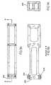
- FIGS. 1 a - bare top and back views of an embodiment of the invention, respectively, showing an instrument with the arms open and without the retractor;
- FIG. 2is a side cutaway view of the embodiment, with the arms open and the body of the retractor positioned to allow access to the proximal end of the shaft;
- FIG. 3is a side cutaway view of the embodiment, with the arms closed and the body of the retractor positioned so that the bore is coaxial with the shaft, and showing the screw of the retractor positioned for insertion into the bore;
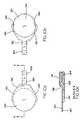
- FIGS. 4 a - bare top and cutaway (along line B-B in FIG. 4 a ) views of the shaft, respectively;
- FIGS. 5 a - bare side (showing a partial section along line A-A in FIG. 4 a ) and back views of the shaft, respectively;
- FIGS. 6 a - bare top and back views of the arms, respectively;
- FIGS. 7 a - care front, side cutaway (along line A-A in FIG. 6 a ), and back views of the arms, respectively;
- FIG. 8is a side view of the arms
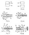
- FIGS. 9 a - care top, side cutaway (along line A-A in FIG. 9 a ), and back views of the collar, respectively;
- FIGS. 10 a - care top, bottom and side cutaway (along line A-A in FIG. 10 a ) views of the extension of the distal end of one of the arms, respectively;
- FIGS. 11 a - care top, cutaway (along line A-A in FIG. 11 a ) and side views of the body of the retractor, respectively;
- FIG. 12is a side view of the screw of the retractor
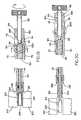
- FIGS. 13-14show damaged or unwanted tissue between vertebral bodies and clearance of the same
- FIGS. 15-16show an exemplary receipt of an implant by the instrument
- FIG. 17shows an exemplary insertion of the implant in between the vertebral bodies using the instrument
- FIG. 18shows an exemplary engagement of the distal end of the screw with the engagement surface of the shaft
- FIGS. 19-20show an exemplary retraction of the distal ends of the arms.
- the instrumentincludes a holder adapted to hold the implant during insertion of the implant between the vertebral bodies, a retractor adapted to retract the holder away from the implant after the insertion, and a guard adapted to prevent the implant from being removed from between the vertebral bodies during the retraction.
- the guardincludes a shaft 50 that has a longitudinal axis, a proximal end 54 that has an engagement surface 60 , and a distal end 64 .
- the shaft 50is tapered to have a narrower cross-section at the distal end 64 than at the proximal end 54 .
- the distal end 64has a curved surface.
- the holderincludes a plurality of arms 70 , each having a proximal end 74 and a distal end 80 .
- Each of the arms 70longitudinally extends alongside the shaft 50 .
- the retractorincludes a bore 84 having a longitudinal axis and a screw 90 that can thread within the bore 84 .
- the screw 90has a head 92 and a distal end 94 .
- the arms 70are adapted to cooperate to hold the implant using the distal ends 80 of the arms 70 such that the implant is longitudinally adjacent the distal end 64 of the shaft 50 . More specifically, the proximal ends 54 of the arms 70 are joined to one another, and the distal ends 80 of the arms 70 can be opened away from one another (as shown in FIG. 2 ) to receive the implant, and closed toward one another (as shown in FIG. 3 ) to hold the implant.
- each arm 70has an outer surface 100
- the instrumentfurther includes a laterally rigid collar 104 that can be slid against the outer surfaces 100 of the arms 70 to open and close the distal ends 80 of the arms 70 .
- each of the outer surfaces 100has a laterally outwardly tapering portion 110 against which the collar 104 can be slid. Accordingly, the imposition of the collar 104 against the tapered portions 110 causes the arms 70 to be forced toward the shaft 50 . The taper of the shaft 50 accommodates this movement of the arms 70 .
- the instrumentfurther includes a handle 108 that is attached to the collar 104 and that can be used to slide the collar 104 .
- each of the distal ends 80 of the arms 70includes an extension 114 that extends beyond the distal end 64 of the shaft 50 , and the implant can be held between the extensions 114 when the distal ends 80 are closed.
- Each extensionincludes a plate 120 having a surface 124 that contacts the implant when the implant is held.
- Each plate 120has a lateral edge 130 and a lateral guard 134 at the edge 130 to prevent the implant from laterally moving from between the plates 120 when the implant is held.
- Each extension 114has a ridge 138 that prevents the plates 120 and the implant from being inserted further in between the vertebral bodies than clinically desired, as described in greater detail below.
- the distal ends 80 of the arms 70are adapted to adjust to accommodate the surface topography of the implant to hold the implant.
- the implant to be insertedtypically has a surface topography such that an upper surface of the implant is substantially parallel to a lower surface of the implant.
- the implantmay have a tapered surface topography such that an upper surface of the implant is not substantially parallel to a lower surface of the implant. This embodiment and other embodiments of the invention accommodate such varied surface topographies to hold either type of implant for insertion.
- each of the arms 70includes a longitudinally extending body 140 .
- Each of the distal ends 80 of the arms 70includes the extension 114 and a coupling whereby the extension 114 is coupled to the body 140 so that the extension 114 can hinge relative to the body 140 .
- the couplingincludes a distal lateral through hole 150 on the extension 114 and a proximal lateral through slot 154 on the extension 114 .
- the couplingfurther includes a distal lateral through hole 160 on the body 140 and a proximal lateral through hole 164 on the body 140 .
- the couplingfurther includes a distal rod 170 passing laterally through the distal through holes 150 , 160 .
- the couplingfurther includes a proximal rod 174 passing laterally through the proximal through hole 150 and the proximal through slot 154 .
- the through slot 154can expand to allow the extension 114 to hinge relative to the body 140 .
- the through slot 154permits the expansion but is biased toward not expanding.
- This feature of the through slot 154can be provided by constructing the extension 114 using a material that provides structural stability but which has some elasticity to permit the expansion when stressed. Suitable materials include, but are not limited to, surgical steel and titanium.
- the retractorincludes a body 180 having the bore 84 and a coupling whereby the body 180 is coupled to the proximal ends 74 of the arms 70 so that the body 180 can hinge relative to the arms 70 .
- the couplingenables the bore 84 to be placed in longitudinally fixed relation to the arms 70 so that if the bore 84 is moved longitudinally, the arms 70 will also move with the bore 84 .
- the couplingalso enables the longitudinal axis of the bore 84 to be aligned coaxial with the longitudinal axis of the shaft 50 .
- This alignmentpermits the screw 90 to be used to effect the retraction, as described in greater detail below.
- the couplingalso enables the body 180 to hinge relative to the arms 70 to allow access to the proximal ends 74 of the arms 70 . Such access may be required during the insertion procedure, as described in greater detail below.
- the body 180includes a trunk 190 having the bore 84 and the coupling includes two curved passageways 194 fixed to the proximal ends 74 of the arms 70 and corresponding hooks 200 fixed to the trunk 190 .
- the travel of the hooks 200 through the passageways 194provides a range of positions through which the trunk 190 can hinge relative to the arms 70 .
- One of the positions(shown, e.g., in FIG. 3 ) is a position in which the bore 84 is in longitudinally fixed relation to the arms 70 and the longitudinal axis of the bore 84 is aligned coaxial with the longitudinal axis of the shaft 50 .
- Another of the positions(shown, e.g., in FIG. 2 ) is a position in which the trunk 190 is positioned to allow access to the proximal end 54 of the shaft 50 .
- the shaft 50is coupled to the arms 70 to prevent lateral movement between the shaft 50 and the arms 70 and allow longitudinal movement between the shaft 50 and the arms 70 .
- the coupling between the shaft 50 and the arms 70includes a lateral through slot 230 through the shaft 50 that extends longitudinally within the shaft 50 , and a pin 234 attached to the arms 70 that passes laterally through the through slot 230 and travels longitudinally within the through slot 230 during the retraction. This feature facilitates the longitudinal movement of the arms 70 with respect to the shaft 50 while helping to maintain the stability of the instrument during use.
- the surgeonfirst prepares the vertebral column for insertion of the implant.
- the surgeonclears away any damaged or unwanted tissue 204 from between the vertebral bodies 210 between which the implant is to be inserted.
- the surgeonthen expands the space between the vertebral bodies 210 enough to accommodate the implant which is to be inserted. Any suitable method for expanding the space in this regard can be used, including methods known in the art.
- the instrument of the inventionis used after the space between the vertebral bodies 210 has been expanded sufficiently to accommodate the implant which is to be inserted. While during the insertion using the instrument some expansion of the space will be effected in many cases due to forces exerted by the surgeon, the instrument is not used primarily for expanding the space prior to the insertion.
- vertebral bodies 210do not need to be cut in any specific manner, and the space does not otherwise need to be prepared, in order for the instrument of the invention to effectively insert the implant and remove the holder. Specifically, for example, there is no need to cut the vertebral bodies 210 , or otherwise prepare the space, so that the implant jams into the space. Novel features and methods of the invention are disclosed herein for avoiding the need for such activities and events.
- the surgeonthen operates the instrument to hold the implant 214 between the plates 120 .
- the surgeonprepares the instrument for receiving the implant 214 by placing the collar 104 in a proximal position that allows the arms 70 to open ( FIG. 2 ). In this position, as shown in magnified view in FIG. 15 , the plates 120 are open and the surgeon places the implant 214 on the lower plate 120 .
- the lateral guard 134 on the lower plate 120prevents the implant 214 from slipping off the lower plate 120 as the surgeon continues to operate the instrument.
- the surgeonmoves the collar 104 to a distal position that closes the arms 70 ( FIG. 3 ). In this position, as shown in magnified view in FIG. 16 , the implant 214 is held between the plates 120 .
- Movement of the collar 104 from the proximal position to the distal positioncauses the collar 104 to engage the laterally outwardly tapering portions 110 of the outer surfaces 100 of the arms 70 . Because the collar 104 is laterally rigid, and the tapering portions 110 gradually increase the thickness of the arms 70 , the engagement of the collar 104 with the tapering portions 110 forces the arms 70 toward the shaft 50 . The taper of the shaft 50 accommodates this movement of the arms 70 . The surgeon is able to move the collar 104 by gripping the handle 108 and sliding the handle 108 toward the proximal ends 74 of the arms 70 or toward the distal ends 80 of the arms 70 .
- the plates 120adjust to the topography of the implant 214 . More specifically, as the plates 120 close on the implant 214 , each of the contact surfaces 124 of the plates 120 seeks to rest flat against the corresponding surfaces of the implant 214 . Whether or not the upper and lower surfaces 220 , 224 of the implant 214 are parallel, the plates 120 are able to move to positions in which the contact surfaces 124 rest flat against the corresponding surfaces 220 , 224 of the implant 214 .
- the extensions 114hinge about the distal rods 170 and, if necessary, the through slots 154 expand as the proximal rods 174 press against the inner surface of the through slots 154 .
- the extensions. 114 in this embodiment and other embodimentsare formed from a material having some elasticity so as to permit the expansion but be biased toward not expanding. This ensures that even as the through slots 154 expand, the extensions 114 provide structural support for holding the implant 214 .
- the lateral guards 134 of the plates 120prevent the implant 214 from exiting laterally from between the plates 120 .
- the surgeonthen inserts the plates 120 between the vertebral bodies 210 with the implant 214 between the plates 120 .
- the surfaces of the plates 120 in this embodiment and other embodimentsare micromachined to be extremely smooth so that the insertion can be accomplished with a minimum of force and a minimum of collateral damage.
- the surgeoncan grip the handle 108 and push the instrument to insert the plates 120 and the implant 214 in between the vertebral bodies 210 .
- the lateral guards 134 of the plates 120press against the implant 214 (depending on the direction of insertion) to assist in urging the implant 214 in between the vertebral bodies 210 , and prevent the implant 214 from exiting laterally from between the plates 120 .
- the shaft 50it is not necessary for the shaft 50 to act as a ram to push the implant 214 in between the vertebral bodies 210 .
- the screw 90rotated to use the shaft 50 in such a manner. The use of the screw 90 is described below, and is for retracting the plates 120 , not for pushing the implant 214 .
- the implant 214is held between the plates 120 , and the arms 70 provide structural support as the surgeon pushes the arms 70 to insert the implant 214 and the plates 120 in between the vertebral bodies 210 .
- the lateral guards 134and primarily the most proximal portions of the lateral guards 134 , press against the implant 214 to help urge the implant 214 in between the vertebral bodies 210 along with the plates 120 .
- the ridges 138limit the extent to which the plates 120 can be inserted between the vertebral bodies 210 during the insertion, because the ridges 138 will contact the sides of the vertebral bodies 210 if the surgeon attempts to insert the plates 120 further than is clinically desirable.
- an instrument of the inventioncan include alternative or additional ridges or protrusions to prevent the implant from being inserted further than is clinically desirable.
- Such protrusionscould also assist the surgeon in maintaining the placement of the implant during the retraction of the holder.
- the guardcould have one or more protrusions that can rest against the side or sides of the vertebral body or bodies during the retraction of the holder. This would be useful, for example, to allow the surgeon to press the protrusion or protrusions against the side or sides to ensure that the placement of the implant is maintained as the holder is retracted.
- the shaft 50can include one or more ridges or other protrusions near or at its distal end 64 that protrude far enough out from the shaft 50 to engage the side (or sides) of the vertebral body (or bodies) 210 if the surgeon attempts to insert the plates 120 further than is clinically desirable.
- each arm 70can include a slot through which a ridge of the shaft 50 is accommodated when the arms 70 are closed and not retracted.
- Each slotcould extend through the extension 114 all the way through the plate 120 . Therefore, each extension 114 could be partially split by the slot.
- Each half of each extension 114could still have enough surface area on its half-plate and enough structural stability to hold the implant 214 , because the halves of the extension 114 could be secured to one another aft of the plate 120 but forward of the distal end 80 of the arm 70 , e.g., the halves can meet near where the extension 114 is coupled to the distal end 80 of the arm 70 .
- the slotswould allow the extensions 114 including the plates 120 to avoid the ridges of the shaft 50 during the retraction.
- the ridges of the shaft 50can be held against the sides of the vertebral bodies 210 during the retraction, to serve as guides to help the surgeon maintain the shaft 50 in place so that the implant 214 remains in place during the retraction.
- a benefit of not needing to prepare the vertebral bodies 210 or the space so that the implant 214 jams into the space so that the plates 120 can be removedis that the instrument of the invention in this embodiment and other embodiments does not rely on the structural integrity of the implant 214 for effective functioning of the instrument. Therefore, implants that are designed to have structural stability when finally inserted in between vertebral bodies, but which do not have a structure capable of withstanding the insertion forces, can be inserted using this embodiment and other embodiments of the invention. In addition, the risk of structural collapse (and possibly dangerous fragmentation) of the implant 214 is minimized by this embodiment and other embodiments of the invention.
- the surgeonmay need to use a hammer to tap the plates 120 and implant 214 in between the vertebral bodies 210 .
- the surgeoncan hinge the body 180 relative to the arms 70 to position the trunk 190 to allow access to the proximal ends 74 of the arms 70 .
- the surgeoncan tap the proximal ends 74 of the arms 70 with the hammer to move the plates 120 and the implant 214 further in between the vertebral bodies 210 .
- the surgeonoperates the instrument to pull the plates 120 out from between the vertebral bodies 210 while preventing the implant 214 from exiting from between the vertebral bodies 210 .
- the bore 84should be in longitudinally fixed relation to the arms 70 during the retraction.
- the longitudinal axis of the bore 84should be coaxial with the longitudinal axis of the shaft 50 during the retraction. Therefore, if the trunk 190 has been positioned to allow access to the proximal ends 74 of the arms 70 , the surgeon can hinge the body 180 to align the longitudinal axis of the bore 84 coaxial with the longitudinal axis of the shaft 50 . Because of the engagement of the hooks 200 with the passageways 194 , this also places the bore 84 in longitudinally fixed relation to the arms 70 , as best shown in FIG. 18 .
- the distal end 94 of the screw 90should engage the engagement surface 60 of the proximal end 54 of the shaft 50 during the retraction. Therefore, if the screw 90 is not already in the bore 84 , the surgeon inserts the screw 90 into the bore 84 and rotates the screw 90 within the bore 84 until the distal end 94 of the screw 90 engages the engagement surface 60 , as best shown in FIG. 18 .
- rotation of the screw 90 within the bore 84effects the retraction by pulling the arms 70 alongside the shaft 50 until the distal ends 80 of the arms 70 no longer hold the implant 214 .
- the distal end 64 of the shaft 50can engage the implant 214 to prevent the implant 214 from being removed from between the vertebral bodies 210 .
- the curvature of the distal end 64 of the shaft 50helps to stabilize the implant 214 so that the implant 214 does not move laterally during the retraction.
- the trunk 190begins to move longitudinally with respect to the shaft 50 , toward the head 92 of the screw 90 , pulling the arms 70 with it using the hooks 200 .
- the arms 70are pulled, the plates 120 are pulled and the implant 214 may be urged in the pulling direction due, e.g., to friction between the plates 120 and the implant 214 .
- the distal end 64 of the shaft 50can engage the implant 214 to remain fixed relative to the implant 214 while the plates 120 are pulled from between the vertebral bodies 210 , it can prevent the implant 214 from being removed from between the vertebral bodies 210 with the plates 120 .
- the surgeonremoves the instrument from the treatment site and the patient's body and closes the wound.
Landscapes
- Health & Medical Sciences (AREA)
- Transplantation (AREA)
- Engineering & Computer Science (AREA)
- Biomedical Technology (AREA)
- Orthopedic Medicine & Surgery (AREA)
- Oral & Maxillofacial Surgery (AREA)
- Physical Education & Sports Medicine (AREA)
- Cardiology (AREA)
- Neurology (AREA)
- Heart & Thoracic Surgery (AREA)
- Vascular Medicine (AREA)
- Life Sciences & Earth Sciences (AREA)
- Animal Behavior & Ethology (AREA)
- General Health & Medical Sciences (AREA)
- Public Health (AREA)
- Veterinary Medicine (AREA)
- Prostheses (AREA)
Abstract
Description
Claims (20)
Priority Applications (3)
| Application Number | Priority Date | Filing Date | Title |
|---|---|---|---|
| US12/214,334US7938837B2 (en) | 2001-04-27 | 2008-06-18 | Femoral ring loader |
| US13/079,468US8690877B2 (en) | 2001-04-27 | 2011-04-04 | Femoral ring loader |
| US14/185,145US20140172110A1 (en) | 2001-04-27 | 2014-02-20 | Femoral ring loader |
Applications Claiming Priority (4)
| Application Number | Priority Date | Filing Date | Title |
|---|---|---|---|
| US09/844,917US6440142B1 (en) | 2001-04-27 | 2001-04-27 | Femoral ring loader |
| US10/075,688US6663638B2 (en) | 2001-04-27 | 2002-02-13 | Femoral ring loader |
| US10/715,968US7404795B2 (en) | 2001-04-27 | 2003-11-18 | Femoral ring loader |
| US12/214,334US7938837B2 (en) | 2001-04-27 | 2008-06-18 | Femoral ring loader |
Related Parent Applications (1)
| Application Number | Title | Priority Date | Filing Date |
|---|---|---|---|
| US10/715,968ContinuationUS7404795B2 (en) | 2001-04-27 | 2003-11-18 | Femoral ring loader |
Related Child Applications (1)
| Application Number | Title | Priority Date | Filing Date |
|---|---|---|---|
| US13/079,468ContinuationUS8690877B2 (en) | 2001-04-27 | 2011-04-04 | Femoral ring loader |
Publications (2)
| Publication Number | Publication Date |
|---|---|
| US20080262504A1 US20080262504A1 (en) | 2008-10-23 |
| US7938837B2true US7938837B2 (en) | 2011-05-10 |
Family
ID=25293962
Family Applications (6)
| Application Number | Title | Priority Date | Filing Date |
|---|---|---|---|
| US09/844,917Expired - LifetimeUS6440142B1 (en) | 2001-04-27 | 2001-04-27 | Femoral ring loader |
| US10/075,688Expired - Fee RelatedUS6663638B2 (en) | 2001-04-27 | 2002-02-13 | Femoral ring loader |
| US10/715,968Expired - Fee RelatedUS7404795B2 (en) | 2001-04-27 | 2003-11-18 | Femoral ring loader |
| US12/214,334Expired - Fee RelatedUS7938837B2 (en) | 2001-04-27 | 2008-06-18 | Femoral ring loader |
| US13/079,468Expired - Fee RelatedUS8690877B2 (en) | 2001-04-27 | 2011-04-04 | Femoral ring loader |
| US14/185,145AbandonedUS20140172110A1 (en) | 2001-04-27 | 2014-02-20 | Femoral ring loader |
Family Applications Before (3)
| Application Number | Title | Priority Date | Filing Date |
|---|---|---|---|
| US09/844,917Expired - LifetimeUS6440142B1 (en) | 2001-04-27 | 2001-04-27 | Femoral ring loader |
| US10/075,688Expired - Fee RelatedUS6663638B2 (en) | 2001-04-27 | 2002-02-13 | Femoral ring loader |
| US10/715,968Expired - Fee RelatedUS7404795B2 (en) | 2001-04-27 | 2003-11-18 | Femoral ring loader |
Family Applications After (2)
| Application Number | Title | Priority Date | Filing Date |
|---|---|---|---|
| US13/079,468Expired - Fee RelatedUS8690877B2 (en) | 2001-04-27 | 2011-04-04 | Femoral ring loader |
| US14/185,145AbandonedUS20140172110A1 (en) | 2001-04-27 | 2014-02-20 | Femoral ring loader |
Country Status (1)
| Country | Link |
|---|---|
| US (6) | US6440142B1 (en) |
Cited By (1)
| Publication number | Priority date | Publication date | Assignee | Title |
|---|---|---|---|---|
| US20110184476A1 (en)* | 2001-04-27 | 2011-07-28 | Spinecore, Inc. | Femoral ring loader |
Families Citing this family (166)
| Publication number | Priority date | Publication date | Assignee | Title |
|---|---|---|---|---|
| US6368325B1 (en) | 1998-05-27 | 2002-04-09 | Nuvasive, Inc. | Bone blocks and methods for inserting bone blocks into intervertebral spaces |
| CA2363254C (en) | 1999-03-07 | 2009-05-05 | Discure Ltd. | Method and apparatus for computerized surgery |
| US6936071B1 (en) | 1999-07-02 | 2005-08-30 | Spine Solutions, Inc. | Intervertebral implant |
| EP1792586B1 (en) | 1999-09-14 | 2012-12-26 | Spine Solutions Inc. | Insert instrument for an implant between vertebrae |
| US8920509B2 (en) | 2000-04-10 | 2014-12-30 | Biomet Manufacturing, Llc | Modular radial head prosthesis |
| US8114163B2 (en) | 2000-04-10 | 2012-02-14 | Biomet Manufacturing Corp. | Method and apparatus for adjusting height and angle for a radial head |
| US6656225B2 (en)* | 2000-04-10 | 2003-12-02 | Biomet Manufacturing Corp. | Modular radial head prostheses |
| US8535382B2 (en) | 2000-04-10 | 2013-09-17 | Biomet Manufacturing, Llc | Modular radial head prostheses |
| US6478800B1 (en) | 2000-05-08 | 2002-11-12 | Depuy Acromed, Inc. | Medical installation tool |
| US6852126B2 (en) | 2000-07-17 | 2005-02-08 | Nuvasive, Inc. | Stackable interlocking intervertebral support system |
| US7204851B2 (en)* | 2000-08-30 | 2007-04-17 | Sdgi Holdings, Inc. | Method and apparatus for delivering an intervertebral disc implant |
| AU2002235351A1 (en)* | 2001-01-26 | 2002-08-06 | Osteotech, Inc. | Implant insertion tool |
| US7235081B2 (en) | 2001-07-16 | 2007-06-26 | Spinecore, Inc. | Wedge plate inserter/impactor and related methods for use in implanting an artificial intervertebral disc |
| US6989032B2 (en) | 2001-07-16 | 2006-01-24 | Spinecore, Inc. | Artificial intervertebral disc |
| US6673113B2 (en) | 2001-10-18 | 2004-01-06 | Spinecore, Inc. | Intervertebral spacer device having arch shaped spring elements |
| US7169182B2 (en) | 2001-07-16 | 2007-01-30 | Spinecore, Inc. | Implanting an artificial intervertebral disc |
| US8940047B2 (en)* | 2001-02-15 | 2015-01-27 | Spinecore, Inc. | Intervertebral spacer device having recessed notch pairs for manipulation using a surgical tool |
| US6929647B2 (en)* | 2001-02-21 | 2005-08-16 | Howmedica Osteonics Corp. | Instrumentation and method for implant insertion |
| FR2824261B1 (en) | 2001-05-04 | 2004-05-28 | Ldr Medical | INTERVERTEBRAL DISC PROSTHESIS AND IMPLEMENTATION METHOD AND TOOLS |
| EP1417000B1 (en) | 2001-07-11 | 2018-07-11 | Nuvasive, Inc. | System for determining nerve proximity during surgery |
| US7695478B2 (en)* | 2001-07-16 | 2010-04-13 | Spinecore, Inc. | Insertion tool for use with intervertebral spacers |
| US7722675B2 (en) | 2001-07-16 | 2010-05-25 | Spinecore, Inc. | Instruments for reorienting vertebral bones for the treatment of scoliosis |
| US6471725B1 (en)* | 2001-07-16 | 2002-10-29 | Third Millenium Engineering, Llc | Porous intervertebral distraction spacers |
| US7118599B2 (en) | 2001-07-16 | 2006-10-10 | Spinecore, Inc. | Artificial intervertebral disc |
| US6478801B1 (en)* | 2001-07-16 | 2002-11-12 | Third Millennium Engineering, Llc | Insertion tool for use with tapered trial intervertebral distraction spacers |
| US7160327B2 (en) | 2001-07-16 | 2007-01-09 | Spinecore, Inc. | Axially compressible artificial intervertebral disc having limited rotation using a captured ball and socket joint with a solid ball and compression locking post |
| US6428544B1 (en)* | 2001-07-16 | 2002-08-06 | Third Millennium Engineering, Llc | Insertion tool for use with trial intervertebral distraction spacers |
| JP2005503857A (en) | 2001-09-25 | 2005-02-10 | ヌバシブ, インコーポレイテッド | Systems and methods for performing surgical procedures and surgical diagnosis |
| US7713302B2 (en) | 2001-10-01 | 2010-05-11 | Spinecore, Inc. | Intervertebral spacer device utilizing a spirally slotted belleville washer having radially spaced concentric grooves |
| US7771477B2 (en) | 2001-10-01 | 2010-08-10 | Spinecore, Inc. | Intervertebral spacer device utilizing a belleville washer having radially spaced concentric grooves |
| US6923814B1 (en)* | 2001-10-30 | 2005-08-02 | Nuvasive, Inc. | System and methods for cervical spinal fusion |
| US8038713B2 (en) | 2002-04-23 | 2011-10-18 | Spinecore, Inc. | Two-component artificial disc replacements |
| US20080027548A9 (en) | 2002-04-12 | 2008-01-31 | Ferree Bret A | Spacerless artificial disc replacements |
| US6660006B2 (en)* | 2002-04-17 | 2003-12-09 | Stryker Spine | Rod persuader |
| US7799086B2 (en) | 2002-04-25 | 2010-09-21 | Zimmer Technology, Inc. | Modular bone implant, tools, and method |
| US7618423B1 (en) | 2002-06-15 | 2009-11-17 | Nuvasive, Inc. | System and method for performing spinal fusion |
| US7582058B1 (en) | 2002-06-26 | 2009-09-01 | Nuvasive, Inc. | Surgical access system and related methods |
| CA2495404C (en) | 2002-08-15 | 2011-05-03 | Justin K. Coppes | Intervertebral disc implant |
| EP1542626B1 (en) | 2002-08-15 | 2012-09-26 | Synthes GmbH | Controlled artificial intervertebral disc implant |
| US7776049B1 (en) | 2002-10-02 | 2010-08-17 | Nuvasive, Inc. | Spinal implant inserter, implant, and method |
| EP1558184A2 (en)* | 2002-10-08 | 2005-08-03 | SDGI Holdings, Inc. | Insertion device and techniques for orthopaedic implants |
| US8137284B2 (en) | 2002-10-08 | 2012-03-20 | Nuvasive, Inc. | Surgical access system and related methods |
| FR2846550B1 (en) | 2002-11-05 | 2006-01-13 | Ldr Medical | INTERVERTEBRAL DISC PROSTHESIS |
| US7204852B2 (en) | 2002-12-13 | 2007-04-17 | Spine Solutions, Inc. | Intervertebral implant, insertion tool and method of inserting same |
| US7691057B2 (en) | 2003-01-16 | 2010-04-06 | Nuvasive, Inc. | Surgical access system and related methods |
| US7887539B2 (en) | 2003-01-24 | 2011-02-15 | Depuy Spine, Inc. | Spinal rod approximators |
| US7988698B2 (en)* | 2003-01-28 | 2011-08-02 | Depuy Spine, Inc. | Spinal rod approximator |
| US6908484B2 (en) | 2003-03-06 | 2005-06-21 | Spinecore, Inc. | Cervical disc replacement |
| WO2004084742A1 (en) | 2003-03-24 | 2004-10-07 | Theken Surgical Llc | Spinal implant adjustment device |
| US7491204B2 (en) | 2003-04-28 | 2009-02-17 | Spine Solutions, Inc. | Instruments and method for preparing an intervertebral space for receiving an artificial disc implant |
| US20040267275A1 (en)* | 2003-06-26 | 2004-12-30 | Cournoyer John R. | Spinal implant holder and rod reduction systems and methods |
| US7803162B2 (en) | 2003-07-21 | 2010-09-28 | Spine Solutions, Inc. | Instruments and method for inserting an intervertebral implant |
| US20050059969A1 (en)* | 2003-09-17 | 2005-03-17 | Depuy Acromed, Inc. | Rod approximator |
| US7905840B2 (en) | 2003-10-17 | 2011-03-15 | Nuvasive, Inc. | Surgical access system and related methods |
| JP4463819B2 (en) | 2003-09-25 | 2010-05-19 | ヌヴァシヴ インコーポレイテッド | Surgical access system |
| US7967826B2 (en) | 2003-10-21 | 2011-06-28 | Theken Spine, Llc | Connector transfer tool for internal structure stabilization systems |
| ATE441376T1 (en) | 2003-12-17 | 2009-09-15 | Depuy Spine Inc | INSTRUMENTS AND PROCEDURES FOR BONE ANCHOR PROCEDURES AND SPINAL BAR REDUCTION |
| US7842044B2 (en) | 2003-12-17 | 2010-11-30 | Depuy Spine, Inc. | Instruments and methods for bone anchor engagement and spinal rod reduction |
| US8123757B2 (en)* | 2003-12-31 | 2012-02-28 | Depuy Spine, Inc. | Inserter instrument and implant clip |
| US7625379B2 (en)* | 2004-01-26 | 2009-12-01 | Warsaw Orthopedic, Inc. | Methods and instrumentation for inserting intervertebral grafts and devices |
| FR2865629B1 (en) | 2004-02-04 | 2007-01-26 | Ldr Medical | INTERVERTEBRAL DISC PROSTHESIS |
| EP2113227B1 (en) | 2004-02-04 | 2015-07-29 | LDR Medical | Intervertebral disc prosthesis |
| US7393361B2 (en) | 2004-02-20 | 2008-07-01 | Spinecore, Inc. | Artificial intervertebral disc having a bored semispherical bearing with a compression locking post and retaining caps |
| US7468076B2 (en) | 2004-02-20 | 2008-12-23 | Spinecore, Inc. | Artificial intervertebral disc having a universal joint |
| US7811292B2 (en)* | 2004-03-02 | 2010-10-12 | Aesculap Implant Systems, Inc. | Surgical instrument for implants |
| US7918891B1 (en) | 2004-03-29 | 2011-04-05 | Nuvasive Inc. | Systems and methods for spinal fusion |
| FR2869528B1 (en) | 2004-04-28 | 2007-02-02 | Ldr Medical | INTERVERTEBRAL DISC PROSTHESIS |
| US7544208B1 (en) | 2004-05-03 | 2009-06-09 | Theken Spine, Llc | Adjustable corpectomy apparatus |
| US7608080B2 (en)* | 2004-07-02 | 2009-10-27 | Warsaw Orthopedic, Inc. | Device for inserting implants |
| US7585326B2 (en)* | 2004-08-06 | 2009-09-08 | Spinalmotion, Inc. | Methods and apparatus for intervertebral disc prosthesis insertion |
| JP2006068086A (en)* | 2004-08-31 | 2006-03-16 | Takiron Co Ltd | Artificial spinal disk insertion tool and tool set |
| DE102004043996B4 (en)* | 2004-09-08 | 2008-04-17 | Aesculap Ag & Co. Kg | Surgical instrument and implant system |
| US8979857B2 (en)* | 2004-10-06 | 2015-03-17 | DePuy Synthes Products, LLC | Modular medical tool and connector |
| WO2006058079A2 (en)* | 2004-11-22 | 2006-06-01 | Endius, Inc. | Expandable device for providing access to the spine |
| FR2879436B1 (en) | 2004-12-22 | 2007-03-09 | Ldr Medical | INTERVERTEBRAL DISC PROSTHESIS |
| US7722622B2 (en) | 2005-02-25 | 2010-05-25 | Synthes Usa, Llc | Implant insertion apparatus and method of use |
| US7951175B2 (en) | 2005-03-04 | 2011-05-31 | Depuy Spine, Inc. | Instruments and methods for manipulating a vertebra |
| US7951172B2 (en) | 2005-03-04 | 2011-05-31 | Depuy Spine Sarl | Constrained motion bone screw assembly |
| USD530423S1 (en) | 2005-03-29 | 2006-10-17 | Nuvasive, Inc. | Intervertebral implant |
| US20060241641A1 (en)* | 2005-04-22 | 2006-10-26 | Sdgi Holdings, Inc. | Methods and instrumentation for distraction and insertion of implants in a spinal disc space |
| US20060293692A1 (en) | 2005-06-02 | 2006-12-28 | Whipple Dale E | Instruments and methods for manipulating a spinal fixation element |
| US8623088B1 (en) | 2005-07-15 | 2014-01-07 | Nuvasive, Inc. | Spinal fusion implant and related methods |
| US8328851B2 (en) | 2005-07-28 | 2012-12-11 | Nuvasive, Inc. | Total disc replacement system and related methods |
| SE0501784L (en)* | 2005-08-05 | 2007-02-06 | Ortoma Ab | Device for application of damping-effect material between vertebrae |
| FR2891135B1 (en) | 2005-09-23 | 2008-09-12 | Ldr Medical Sarl | INTERVERTEBRAL DISC PROSTHESIS |
| US7618459B2 (en)* | 2005-09-26 | 2009-11-17 | Infinity Orthopedics Ltd. | Universal spinal disc implant system |
| US20070161998A1 (en)* | 2005-10-28 | 2007-07-12 | Dale Whipple | Instruments and Methods For Manipulating A Spinal Rod |
| US7867237B2 (en)* | 2005-10-31 | 2011-01-11 | Depuy Spine, Inc. | Arthroplasty revision device and method |
| US20070123903A1 (en)* | 2005-10-31 | 2007-05-31 | Depuy Spine, Inc. | Medical Device installation tool and methods of use |
| US20070123904A1 (en)* | 2005-10-31 | 2007-05-31 | Depuy Spine, Inc. | Distraction instrument and method for distracting an intervertebral site |
| EP1787603A1 (en) | 2005-11-18 | 2007-05-23 | Zimmer GmbH | Basis-platform for an artificial joint |
| FR2893838B1 (en) | 2005-11-30 | 2008-08-08 | Ldr Medical Soc Par Actions Si | PROSTHESIS OF INTERVERTEBRAL DISC AND INSTRUMENTATION OF INSERTION OF THE PROSTHESIS BETWEEN VERTEBRATES |
| US7988695B2 (en) | 2005-12-21 | 2011-08-02 | Theken Spine, Llc | Articulated delivery instrument |
| US7867279B2 (en)* | 2006-01-23 | 2011-01-11 | Depuy Spine, Inc. | Intervertebral disc prosthesis |
| US8377072B2 (en)* | 2006-02-06 | 2013-02-19 | Depuy Spine, Inc. | Medical device installation tool |
| US7806901B2 (en)* | 2006-03-17 | 2010-10-05 | Depuy Spine, Inc. | Arthroplasty final seating instruments |
| US7976549B2 (en) | 2006-03-23 | 2011-07-12 | Theken Spine, Llc | Instruments for delivering spinal implants |
| US8303601B2 (en) | 2006-06-07 | 2012-11-06 | Stryker Spine | Collet-activated distraction wedge inserter |
| USD741488S1 (en) | 2006-07-17 | 2015-10-20 | Nuvasive, Inc. | Spinal fusion implant |
| EP3628244A1 (en) | 2006-07-24 | 2020-04-01 | Centinel Spine Schweiz GmbH | Intervertebral implant with keel |
| BRPI0714955A2 (en) | 2006-07-31 | 2013-07-23 | Systhes Gmbh | instrument system and method for preparing an intervertebral space to receive an implant, and milling guide for use with an instrument system |
| US8506636B2 (en) | 2006-09-08 | 2013-08-13 | Theken Spine, Llc | Offset radius lordosis |
| US7686809B2 (en) | 2006-09-25 | 2010-03-30 | Stryker Spine | Rod inserter and rod with reduced diameter end |
| US8465546B2 (en)* | 2007-02-16 | 2013-06-18 | Ldr Medical | Intervertebral disc prosthesis insertion assemblies |
| US8673005B1 (en) | 2007-03-07 | 2014-03-18 | Nuvasive, Inc. | System and methods for spinal fusion |
| US8172847B2 (en)* | 2007-03-29 | 2012-05-08 | Depuy Spine, Inc. | In-line rod reduction device and methods |
| US8361080B2 (en)* | 2007-03-30 | 2013-01-29 | Depuy Spine, Inc. | Implant inserter having a bifurcated adjustable stop |
| US20080255574A1 (en)* | 2007-04-13 | 2008-10-16 | Zimmer Technology, Inc. | Instrument for insertion of prosthetic components |
| US8197484B2 (en)* | 2007-04-24 | 2012-06-12 | Depuy Products, Inc. | Assembly for minimally invasive reduction of hip fracture |
| US8579910B2 (en)* | 2007-05-18 | 2013-11-12 | DePuy Synthes Products, LLC | Insertion blade assembly and method of use |
| FR2916956B1 (en) | 2007-06-08 | 2012-12-14 | Ldr Medical | INTERSOMATIC CAGE, INTERVERTEBRAL PROSTHESIS, ANCHORING DEVICE AND IMPLANTATION INSTRUMENTATION |
| US8486081B2 (en) | 2007-07-23 | 2013-07-16 | DePuy Synthes Products, LLC | Implant insertion device and method |
| US7887541B2 (en)* | 2007-07-26 | 2011-02-15 | Depuy Spine, Inc. | Spinal rod reduction instruments and methods for use |
| USD671645S1 (en) | 2007-09-18 | 2012-11-27 | Nuvasive, Inc. | Intervertebral implant |
| US8790348B2 (en)* | 2007-09-28 | 2014-07-29 | Depuy Spine, Inc. | Dual pivot instrument for reduction of a fixation element and method of use |
| US8591587B2 (en) | 2007-10-30 | 2013-11-26 | Aesculap Implant Systems, Llc | Vertebral body replacement device and method for use to maintain a space between two vertebral bodies within a spine |
| US8142441B2 (en)* | 2008-10-16 | 2012-03-27 | Aesculap Implant Systems, Llc | Surgical instrument and method of use for inserting an implant between two bones |
| US9101491B2 (en) | 2007-12-28 | 2015-08-11 | Nuvasive, Inc. | Spinal surgical implant and related methods |
| US8535323B2 (en)* | 2008-01-25 | 2013-09-17 | DePuy Synthes Products, LLC | Constraining ring inserter |
| US8343163B1 (en) | 2008-02-14 | 2013-01-01 | Nuvasive, Inc. | Spinal implant installation device |
| US8840622B1 (en) | 2008-02-14 | 2014-09-23 | Nuvasive, Inc. | Implant installation assembly and related methods |
| US8083796B1 (en) | 2008-02-29 | 2011-12-27 | Nuvasive, Inc. | Implants and methods for spinal fusion |
| USD599019S1 (en) | 2008-03-07 | 2009-08-25 | Nuvasive, Inc. | Spinal fusion implant |
| US8608746B2 (en) | 2008-03-10 | 2013-12-17 | DePuy Synthes Products, LLC | Derotation instrument with reduction functionality |
| US8709015B2 (en) | 2008-03-10 | 2014-04-29 | DePuy Synthes Products, LLC | Bilateral vertebral body derotation system |
| CA2722918C (en) | 2008-05-07 | 2014-07-15 | George A. Frey | Methods and apparatus for insertion of intervertebral implants and devices therefor |
| US9615938B2 (en) | 2008-05-07 | 2017-04-11 | Mighty Oak Medical, Inc. | Methods and apparatus for insertion of implant material |
| US10973556B2 (en) | 2008-06-17 | 2021-04-13 | DePuy Synthes Products, Inc. | Adjustable implant assembly |
| EP2340002B1 (en) | 2008-10-06 | 2015-03-25 | Providence Health System - Oregon | Foam medical devices and methods |
| USD621509S1 (en) | 2008-10-15 | 2010-08-10 | Nuvasive, Inc. | Intervertebral implant |
| WO2010075195A1 (en) | 2008-12-22 | 2010-07-01 | Synthes Usa, Llc | Orthopedic implant with flexible keel |
| USD754346S1 (en) | 2009-03-02 | 2016-04-19 | Nuvasive, Inc. | Spinal fusion implant |
| US9387090B2 (en) | 2009-03-12 | 2016-07-12 | Nuvasive, Inc. | Vertebral body replacement |
| US9687357B2 (en) | 2009-03-12 | 2017-06-27 | Nuvasive, Inc. | Vertebral body replacement |
| US8906033B2 (en) | 2009-03-30 | 2014-12-09 | DePuy Synthes Products, LLC | Cervical motion disc inserter |
| US8287597B1 (en) | 2009-04-16 | 2012-10-16 | Nuvasive, Inc. | Method and apparatus for performing spine surgery |
| US9351845B1 (en) | 2009-04-16 | 2016-05-31 | Nuvasive, Inc. | Method and apparatus for performing spine surgery |
| US8206394B2 (en) | 2009-05-13 | 2012-06-26 | Depuy Spine, Inc. | Torque limited instrument for manipulating a spinal rod relative to a bone anchor |
| US8109935B2 (en) | 2009-05-15 | 2012-02-07 | Musculoskeletal Transplant Foundation | Implant inserter device |
| US8394125B2 (en)* | 2009-07-24 | 2013-03-12 | Zyga Technology, Inc. | Systems and methods for facet joint treatment |
| USD731063S1 (en) | 2009-10-13 | 2015-06-02 | Nuvasive, Inc. | Spinal fusion implant |
| US9028553B2 (en) | 2009-11-05 | 2015-05-12 | DePuy Synthes Products, Inc. | Self-pivoting spinal implant and associated instrumentation |
| US9301853B2 (en) | 2010-04-09 | 2016-04-05 | DePuy Synthes Products, Inc. | Holder for implantation and extraction of prosthesis |
| US8439932B2 (en) | 2010-05-03 | 2013-05-14 | Biomet Manufacturing Corp. | Submuscular plating system |
| US8790406B1 (en) | 2011-04-01 | 2014-07-29 | William D. Smith | Systems and methods for performing spine surgery |
| US9198765B1 (en) | 2011-10-31 | 2015-12-01 | Nuvasive, Inc. | Expandable spinal fusion implants and related methods |
| USD721808S1 (en) | 2011-11-03 | 2015-01-27 | Nuvasive, Inc. | Intervertebral implant |
| USD675320S1 (en) | 2011-11-03 | 2013-01-29 | Nuvasive, Inc. | Intervertebral implant |
| US8771277B2 (en)* | 2012-05-08 | 2014-07-08 | Globus Medical, Inc | Device and a method for implanting a spinous process fixation device |
| ES2544274T3 (en)* | 2012-10-24 | 2015-08-28 | Waldemar Link Gmbh & Co. Kg | Support for a medical implant |
| US10022245B2 (en) | 2012-12-17 | 2018-07-17 | DePuy Synthes Products, Inc. | Polyaxial articulating instrument |
| USD745159S1 (en) | 2013-10-10 | 2015-12-08 | Nuvasive, Inc. | Intervertebral implant |
| US10478313B1 (en) | 2014-01-10 | 2019-11-19 | Nuvasive, Inc. | Spinal fusion implant and related methods |
| USD858769S1 (en) | 2014-11-20 | 2019-09-03 | Nuvasive, Inc. | Intervertebral implant |
| US10413427B2 (en)* | 2015-03-19 | 2019-09-17 | Warsaw Orthopedic, Inc. | Spinal implant system and method |
| US10543106B2 (en)* | 2016-04-05 | 2020-01-28 | Alphatec Spine, Inc. | Inserter with impact and rotational drive advancement and implant holder with implant auto release |
| EP3287088B1 (en) | 2016-08-24 | 2019-01-09 | Biedermann Technologies GmbH & Co. KG | Instrument for locking and unlocking a head of a bone anchor in a polyaxial bone anchoring device |
| US10966843B2 (en) | 2017-07-18 | 2021-04-06 | DePuy Synthes Products, Inc. | Implant inserters and related methods |
| US11045331B2 (en) | 2017-08-14 | 2021-06-29 | DePuy Synthes Products, Inc. | Intervertebral implant inserters and related methods |
| US10966762B2 (en) | 2017-12-15 | 2021-04-06 | Medos International Sarl | Unilateral implant holders and related methods |
| US11096802B2 (en) | 2018-03-03 | 2021-08-24 | K2M, Inc. | Intervertebral trial with marker |
| USD1004774S1 (en) | 2019-03-21 | 2023-11-14 | Medos International Sarl | Kerrison rod reducer |
| US11291481B2 (en) | 2019-03-21 | 2022-04-05 | Medos International Sarl | Rod reducers and related methods |
| US11291482B2 (en) | 2019-03-21 | 2022-04-05 | Medos International Sarl | Rod reducers and related methods |
| EP4240262B1 (en) | 2020-11-09 | 2024-12-04 | Medos International Sàrl | Biplanar forceps reducers |
| US12232790B2 (en) | 2022-12-30 | 2025-02-25 | IvyTech Design LLC | Adjustable angle orthopedic distractor, compressor, and distractor-compressor |
Citations (21)
| Publication number | Priority date | Publication date | Assignee | Title |
|---|---|---|---|---|
| US2167287A (en) | 1934-02-10 | 1939-07-25 | Leon A Witter | Piston skirt expander |
| US3486505A (en)* | 1967-05-22 | 1969-12-30 | Gordon M Morrison | Orthopedic surgical instrument |
| US5020519A (en) | 1990-12-07 | 1991-06-04 | Zimmer, Inc. | Sagittal approximator |
| US5122130A (en) | 1988-03-23 | 1992-06-16 | Waldemar Link Gmbh & Co. | Forceps for inserting intervertebral device |
| US5431658A (en)* | 1994-02-14 | 1995-07-11 | Moskovich; Ronald | Facilitator for vertebrae grafts and prostheses |
| US5720751A (en) | 1996-11-27 | 1998-02-24 | Jackson; Roger P. | Tools for use in seating spinal rods in open ended implants |
| US5782830A (en) | 1995-10-16 | 1998-07-21 | Sdgi Holdings, Inc. | Implant insertion device |
| US6004326A (en) | 1997-09-10 | 1999-12-21 | United States Surgical | Method and instrumentation for implant insertion |
| US6083225A (en) | 1996-03-14 | 2000-07-04 | Surgical Dynamics, Inc. | Method and instrumentation for implant insertion |
| US6159215A (en) | 1997-12-19 | 2000-12-12 | Depuy Acromed, Inc. | Insertion instruments and method for delivering a vertebral body spacer |
| US6174311B1 (en) | 1998-10-28 | 2001-01-16 | Sdgi Holdings, Inc. | Interbody fusion grafts and instrumentation |
| US6261296B1 (en) | 1998-10-02 | 2001-07-17 | Synthes U.S.A. | Spinal disc space distractor |
| US20010010001A1 (en) | 1999-01-25 | 2001-07-26 | Michelson Gary K. | Instrumentation and method for creating an intervertebral space for receiving an implant |
| US6267763B1 (en) | 1999-03-31 | 2001-07-31 | Surgical Dynamics, Inc. | Method and apparatus for spinal implant insertion |
| US6319257B1 (en) | 1999-12-20 | 2001-11-20 | Kinamed, Inc. | Inserter assembly |
| US20020099377A1 (en) | 1998-10-20 | 2002-07-25 | Zucherman James F. | Mating insertion instruments for spinal implants and methods of use |
| US6440142B1 (en)* | 2001-04-27 | 2002-08-27 | Third Millennium Engineering, Llc | Femoral ring loader |
| US6478800B1 (en) | 2000-05-08 | 2002-11-12 | Depuy Acromed, Inc. | Medical installation tool |
| US20030028197A1 (en) | 2000-07-06 | 2003-02-06 | Hanson David A. | Bone implants and methods |
| US20030083747A1 (en) | 2001-10-30 | 2003-05-01 | Osteotech, Inc. | Bone implant and isertion tools |
| US6652533B2 (en)* | 2001-09-20 | 2003-11-25 | Depuy Acromed, Inc. | Medical inserter tool with slaphammer |
Family Cites Families (4)
| Publication number | Priority date | Publication date | Assignee | Title |
|---|---|---|---|---|
| US7452359B1 (en)* | 1988-06-13 | 2008-11-18 | Warsaw Orthopedic, Inc. | Apparatus for inserting spinal implants |
| US6287314B1 (en)* | 1998-04-21 | 2001-09-11 | Advanced Cardiovascular Systems, Inc. | Stent deploying catheter system |
| US6368325B1 (en)* | 1998-05-27 | 2002-04-09 | Nuvasive, Inc. | Bone blocks and methods for inserting bone blocks into intervertebral spaces |
| US6422778B2 (en)* | 2000-04-03 | 2002-07-23 | 3M Innovative Properties Company | Surgical prep solution applicator system and methods |
- 2001
- 2001-04-27USUS09/844,917patent/US6440142B1/ennot_activeExpired - Lifetime
- 2002
- 2002-02-13USUS10/075,688patent/US6663638B2/ennot_activeExpired - Fee Related
- 2003
- 2003-11-18USUS10/715,968patent/US7404795B2/ennot_activeExpired - Fee Related
- 2008
- 2008-06-18USUS12/214,334patent/US7938837B2/ennot_activeExpired - Fee Related
- 2011
- 2011-04-04USUS13/079,468patent/US8690877B2/ennot_activeExpired - Fee Related
- 2014
- 2014-02-20USUS14/185,145patent/US20140172110A1/ennot_activeAbandoned
Patent Citations (25)
| Publication number | Priority date | Publication date | Assignee | Title |
|---|---|---|---|---|
| US2167287A (en) | 1934-02-10 | 1939-07-25 | Leon A Witter | Piston skirt expander |
| US3486505A (en)* | 1967-05-22 | 1969-12-30 | Gordon M Morrison | Orthopedic surgical instrument |
| US5122130A (en) | 1988-03-23 | 1992-06-16 | Waldemar Link Gmbh & Co. | Forceps for inserting intervertebral device |
| US5020519A (en) | 1990-12-07 | 1991-06-04 | Zimmer, Inc. | Sagittal approximator |
| US5431658A (en)* | 1994-02-14 | 1995-07-11 | Moskovich; Ronald | Facilitator for vertebrae grafts and prostheses |
| US5782830A (en) | 1995-10-16 | 1998-07-21 | Sdgi Holdings, Inc. | Implant insertion device |
| US6066174A (en) | 1995-10-16 | 2000-05-23 | Sdgi Holdings, Inc. | Implant insertion device |
| US6083225A (en) | 1996-03-14 | 2000-07-04 | Surgical Dynamics, Inc. | Method and instrumentation for implant insertion |
| US5720751A (en) | 1996-11-27 | 1998-02-24 | Jackson; Roger P. | Tools for use in seating spinal rods in open ended implants |
| US6004326A (en) | 1997-09-10 | 1999-12-21 | United States Surgical | Method and instrumentation for implant insertion |
| US6159215A (en) | 1997-12-19 | 2000-12-12 | Depuy Acromed, Inc. | Insertion instruments and method for delivering a vertebral body spacer |
| US6261296B1 (en) | 1998-10-02 | 2001-07-17 | Synthes U.S.A. | Spinal disc space distractor |
| US20020099377A1 (en) | 1998-10-20 | 2002-07-25 | Zucherman James F. | Mating insertion instruments for spinal implants and methods of use |
| US6174311B1 (en) | 1998-10-28 | 2001-01-16 | Sdgi Holdings, Inc. | Interbody fusion grafts and instrumentation |
| US20010010001A1 (en) | 1999-01-25 | 2001-07-26 | Michelson Gary K. | Instrumentation and method for creating an intervertebral space for receiving an implant |
| US6267763B1 (en) | 1999-03-31 | 2001-07-31 | Surgical Dynamics, Inc. | Method and apparatus for spinal implant insertion |
| US6319257B1 (en) | 1999-12-20 | 2001-11-20 | Kinamed, Inc. | Inserter assembly |
| US6478800B1 (en) | 2000-05-08 | 2002-11-12 | Depuy Acromed, Inc. | Medical installation tool |
| US6755841B2 (en)* | 2000-05-08 | 2004-06-29 | Depuy Acromed, Inc. | Medical installation tool |
| US20030028197A1 (en) | 2000-07-06 | 2003-02-06 | Hanson David A. | Bone implants and methods |
| US6440142B1 (en)* | 2001-04-27 | 2002-08-27 | Third Millennium Engineering, Llc | Femoral ring loader |
| US6663638B2 (en)* | 2001-04-27 | 2003-12-16 | Spinecore, Inc. | Femoral ring loader |
| US7404795B2 (en)* | 2001-04-27 | 2008-07-29 | Spinecore, Inc. | Femoral ring loader |
| US6652533B2 (en)* | 2001-09-20 | 2003-11-25 | Depuy Acromed, Inc. | Medical inserter tool with slaphammer |
| US20030083747A1 (en) | 2001-10-30 | 2003-05-01 | Osteotech, Inc. | Bone implant and isertion tools |
Cited By (2)
| Publication number | Priority date | Publication date | Assignee | Title |
|---|---|---|---|---|
| US20110184476A1 (en)* | 2001-04-27 | 2011-07-28 | Spinecore, Inc. | Femoral ring loader |
| US8690877B2 (en)* | 2001-04-27 | 2014-04-08 | Spinecore, Inc. | Femoral ring loader |
Also Published As
| Publication number | Publication date |
|---|---|
| US20040102790A1 (en) | 2004-05-27 |
| US6663638B2 (en) | 2003-12-16 |
| US20020161375A1 (en) | 2002-10-31 |
| US8690877B2 (en) | 2014-04-08 |
| US20080262504A1 (en) | 2008-10-23 |
| US20110184476A1 (en) | 2011-07-28 |
| US7404795B2 (en) | 2008-07-29 |
| US20140172110A1 (en) | 2014-06-19 |
| US6440142B1 (en) | 2002-08-27 |
Similar Documents
| Publication | Publication Date | Title |
|---|---|---|
| US7938837B2 (en) | Femoral ring loader | |
| US7507255B2 (en) | Insertion tool for use with trial intervertebral distraction spacers | |
| EP2051660B1 (en) | Apparatus for inserting an implant | |
| US6471725B1 (en) | Porous intervertebral distraction spacers | |
| US6562047B2 (en) | Vertebral bone distraction instruments | |
| US7153310B2 (en) | Vertebral bone distraction instruments | |
| US6554864B2 (en) | Surgical method of treating scoliosis | |
| US6805716B2 (en) | Orthopedic device set for reorienting vertebral bones for the treatment of scoliosis | |
| US6837904B2 (en) | Method of surgically treating scoliosis | |
| US6436102B1 (en) | Method of distracting vertebral bones | |
| US8608752B2 (en) | Trial intervertebral distraction spacers | |
| US8348958B2 (en) | Insertion tool for use with intervertebral spacers | |
| US20030014115A1 (en) | Insertion tool for use with intervertebral spacers | |
| US6890356B2 (en) | Surgical method of treating scoliosis | |
| US20040158326A1 (en) | Instruments for reorienting vertebral bones for the treatment of scoliosis | |
| US8038717B2 (en) | Method of distracting vertebral bones |
Legal Events
| Date | Code | Title | Description |
|---|---|---|---|
| AS | Assignment | Owner name:THIRD MILLENNIUM ENGINEERING, LLC, NEW JERSEY Free format text:ASSIGNMENT OF ASSIGNORS INTEREST;ASSIGNORS:RALPH, JAMES D.;TATAR, STEPHEN;REEL/FRAME:026109/0686 Effective date:20020213 | |
| AS | Assignment | Owner name:SPINECORE, INC., NEW JERSEY Free format text:ASSIGNMENT OF ASSIGNORS INTEREST;ASSIGNOR:THIRD MILLENNIUM ENGINEERING, LLC;REEL/FRAME:026110/0379 Effective date:20030121 | |
| STCF | Information on status: patent grant | Free format text:PATENTED CASE | |
| FPAY | Fee payment | Year of fee payment:4 | |
| FEPP | Fee payment procedure | Free format text:MAINTENANCE FEE REMINDER MAILED (ORIGINAL EVENT CODE: REM.); ENTITY STATUS OF PATENT OWNER: LARGE ENTITY | |
| LAPS | Lapse for failure to pay maintenance fees | Free format text:PATENT EXPIRED FOR FAILURE TO PAY MAINTENANCE FEES (ORIGINAL EVENT CODE: EXP.); ENTITY STATUS OF PATENT OWNER: LARGE ENTITY | |
| STCH | Information on status: patent discontinuation | Free format text:PATENT EXPIRED DUE TO NONPAYMENT OF MAINTENANCE FEES UNDER 37 CFR 1.362 | |
| FP | Lapsed due to failure to pay maintenance fee | Effective date:20190510 | |
| AS | Assignment | Owner name:HOWMEDICA OTEONICS CORP., NEW JERSEY Free format text:MERGER;ASSIGNOR:SPINECORE, INC.;REEL/FRAME:053897/0621 Effective date:20190327 | |
| AS | Assignment | Owner name:HOWMEDICA OSTEONICS CORP., NEW JERSEY Free format text:CORRECTIVE ASSIGNMENT TO CORRECT THE ASSIGNEE NAME PREVIOUSLY RECORDED AT REEL: 053897 FRAME: 0621. ASSIGNOR(S) HEREBY CONFIRMS THE ASSIGNMENT;ASSIGNOR:SPINECORE, INC.;REEL/FRAME:053941/0753 Effective date:20190327 |