US7938836B2 - Driver assembly for simultaneous axial delivery of spinal implants - Google Patents
Driver assembly for simultaneous axial delivery of spinal implantsDownload PDFInfo
- Publication number
- US7938836B2 US7938836B2US11/259,614US25961405AUS7938836B2US 7938836 B2US7938836 B2US 7938836B2US 25961405 AUS25961405 AUS 25961405AUS 7938836 B2US7938836 B2US 7938836B2
- Authority
- US
- United States
- Prior art keywords
- component
- proximal
- distal
- driver
- vertebral body
- Prior art date
- Legal status (The legal status is an assumption and is not a legal conclusion. Google has not performed a legal analysis and makes no representation as to the accuracy of the status listed.)
- Active, expires
Links
- 239000007943implantSubstances0.000titleclaimsabstractdescription28
- 230000033001locomotionEffects0.000claimsabstractdescription69
- 238000013459approachMethods0.000claimsabstractdescription11
- 239000012620biological materialSubstances0.000claimsabstractdescription11
- 230000009969flowable effectEffects0.000claimsabstractdescription11
- 230000009977dual effectEffects0.000claimsdescription37
- 239000000017hydrogelSubstances0.000claimsdescription12
- 229920001971elastomerPolymers0.000claimsdescription9
- 239000000806elastomerSubstances0.000claimsdescription9
- 239000000203mixtureSubstances0.000claimsdescription6
- 229920001296polysiloxanePolymers0.000claimsdescription4
- 210000003484anatomyAnatomy0.000claimsdescription3
- 230000006978adaptationEffects0.000claims4
- 238000011065in-situ storageMethods0.000claims2
- 239000000463materialSubstances0.000abstractdescription37
- 238000000034methodMethods0.000abstractdescription27
- 230000000712assemblyEffects0.000abstractdescription26
- 238000000429assemblyMethods0.000abstractdescription26
- 238000004321preservationMethods0.000abstractdescription26
- 230000008569processEffects0.000abstractdescription11
- 210000000988bone and boneAnatomy0.000description87
- 239000012528membraneSubstances0.000description28
- 230000014759maintenance of locationEffects0.000description26
- 239000011295pitchSubstances0.000description21
- 208000002193PainDiseases0.000description10
- 238000003780insertionMethods0.000description9
- 230000037431insertionEffects0.000description9
- 230000004927fusionEffects0.000description8
- 239000010410layerSubstances0.000description8
- 230000035882stressEffects0.000description8
- 238000002560therapeutic procedureMethods0.000description8
- 238000002347injectionMethods0.000description7
- 239000007924injectionSubstances0.000description7
- 210000005036nerveAnatomy0.000description7
- 230000006641stabilisationEffects0.000description7
- 238000011105stabilizationMethods0.000description7
- 238000001356surgical procedureMethods0.000description7
- 230000006378damageEffects0.000description6
- 230000007850degenerationEffects0.000description6
- 239000000835fiberSubstances0.000description6
- 239000012530fluidSubstances0.000description6
- 238000011282treatmentMethods0.000description6
- 210000004705lumbosacral regionAnatomy0.000description5
- 210000000278spinal cordAnatomy0.000description5
- 230000001225therapeutic effectEffects0.000description5
- XLYOFNOQVPJJNP-UHFFFAOYSA-NwaterSubstancesOXLYOFNOQVPJJNP-UHFFFAOYSA-N0.000description5
- 102000008186CollagenHuman genes0.000description4
- 108010035532CollagenProteins0.000description4
- 208000003618Intervertebral Disc DisplacementDiseases0.000description4
- 229920001436collagenPolymers0.000description4
- 238000004891communicationMethods0.000description4
- 230000001054cortical effectEffects0.000description4
- 230000007423decreaseEffects0.000description4
- 208000014674injuryDiseases0.000description4
- 230000002829reductive effectEffects0.000description4
- 239000000243solutionSubstances0.000description4
- 208000008930Low Back PainDiseases0.000description3
- 208000027418Wounds and injuryDiseases0.000description3
- 230000015572biosynthetic processEffects0.000description3
- 230000001010compromised effectEffects0.000description3
- 238000009826distributionMethods0.000description3
- 238000000605extractionMethods0.000description3
- 238000002513implantationMethods0.000description3
- 230000003993interactionEffects0.000description3
- 210000003041ligamentAnatomy0.000description3
- 230000035790physiological processes and functionsEffects0.000description3
- 230000000717retained effectEffects0.000description3
- 229920002379silicone rubberPolymers0.000description3
- 239000011800void materialSubstances0.000description3
- 230000009471actionEffects0.000description2
- 230000032683agingEffects0.000description2
- 230000004888barrier functionEffects0.000description2
- 238000005452bendingMethods0.000description2
- 230000008901benefitEffects0.000description2
- 210000000845cartilageAnatomy0.000description2
- 230000006835compressionEffects0.000description2
- 238000007906compressionMethods0.000description2
- 238000005520cutting processMethods0.000description2
- 230000003247decreasing effectEffects0.000description2
- 238000013461designMethods0.000description2
- 238000010586diagramMethods0.000description2
- 201000010099diseaseDiseases0.000description2
- 208000037265diseases, disorders, signs and symptomsDiseases0.000description2
- 238000005553drillingMethods0.000description2
- 230000000694effectsEffects0.000description2
- 238000005516engineering processMethods0.000description2
- 230000010006flightEffects0.000description2
- 239000012634fragmentSubstances0.000description2
- 238000011068loading methodMethods0.000description2
- 230000005012migrationEffects0.000description2
- 238000013508migrationMethods0.000description2
- 210000003205muscleAnatomy0.000description2
- 230000037361pathwayEffects0.000description2
- 230000008439repair processEffects0.000description2
- 238000010079rubber tappingMethods0.000description2
- 239000012812sealant materialSubstances0.000description2
- 239000004945silicone rubberSubstances0.000description2
- 230000003068static effectEffects0.000description2
- 210000000115thoracic cavityAnatomy0.000description2
- 210000001519tissueAnatomy0.000description2
- 210000002517zygapophyseal jointAnatomy0.000description2
- KIUKXJAPPMFGSW-DNGZLQJQSA-N(2S,3S,4S,5R,6R)-6-[(2S,3R,4R,5S,6R)-3-Acetamido-2-[(2S,3S,4R,5R,6R)-6-[(2R,3R,4R,5S,6R)-3-acetamido-2,5-dihydroxy-6-(hydroxymethyl)oxan-4-yl]oxy-2-carboxy-4,5-dihydroxyoxan-3-yl]oxy-5-hydroxy-6-(hydroxymethyl)oxan-4-yl]oxy-3,4,5-trihydroxyoxane-2-carboxylic acidChemical compoundCC(=O)N[C@H]1[C@H](O)O[C@H](CO)[C@@H](O)[C@@H]1O[C@H]1[C@H](O)[C@@H](O)[C@H](O[C@H]2[C@@H]([C@@H](O[C@H]3[C@@H]([C@@H](O)[C@H](O)[C@H](O3)C(O)=O)O)[C@H](O)[C@@H](CO)O2)NC(C)=O)[C@@H](C(O)=O)O1KIUKXJAPPMFGSW-DNGZLQJQSA-N0.000description1
- 208000008035Back PainDiseases0.000description1
- 229910000684Cobalt-chromeInorganic materials0.000description1
- 208000032170Congenital AbnormalitiesDiseases0.000description1
- 208000034657ConvalescenceDiseases0.000description1
- 229910000599Cr alloyInorganic materials0.000description1
- 208000036829Device dislocationDiseases0.000description1
- 208000032766Device expulsionDiseases0.000description1
- 208000032765Device extrusionDiseases0.000description1
- 241000722985FidiaSpecies0.000description1
- 206010018852HaematomaDiseases0.000description1
- 206010061246Intervertebral disc degenerationDiseases0.000description1
- 206010050296Intervertebral disc protrusionDiseases0.000description1
- 206010061310Nerve root injuryDiseases0.000description1
- 208000008558OsteophyteDiseases0.000description1
- 102000016611ProteoglycansHuman genes0.000description1
- 108010067787ProteoglycansProteins0.000description1
- 208000008765SciaticaDiseases0.000description1
- FAPWRFPIFSIZLT-UHFFFAOYSA-MSodium chlorideChemical compound[Na+].[Cl-]FAPWRFPIFSIZLT-UHFFFAOYSA-M0.000description1
- 206010041591Spinal osteoarthritisDiseases0.000description1
- 229910001069Ti alloyInorganic materials0.000description1
- 229910000883Ti6Al4VInorganic materials0.000description1
- 238000005299abrasionMethods0.000description1
- 229910045601alloyInorganic materials0.000description1
- 239000000956alloySubstances0.000description1
- 238000004873anchoringMethods0.000description1
- 230000003416augmentationEffects0.000description1
- 230000036772blood pressureEffects0.000description1
- 230000037396body weightEffects0.000description1
- 239000002639bone cementSubstances0.000description1
- 230000015556catabolic processEffects0.000description1
- 239000010952cobalt-chromeSubstances0.000description1
- 210000002808connective tissueAnatomy0.000description1
- 230000008878couplingEffects0.000description1
- 238000010168coupling processMethods0.000description1
- 238000005859coupling reactionMethods0.000description1
- 230000006837decompressionEffects0.000description1
- 230000005786degenerative changesEffects0.000description1
- 230000006866deteriorationEffects0.000description1
- 238000011161developmentMethods0.000description1
- 230000018109developmental processEffects0.000description1
- 238000002059diagnostic imagingMethods0.000description1
- 238000002224dissectionMethods0.000description1
- 239000003814drugSubstances0.000description1
- 229940079593drugDrugs0.000description1
- 239000013536elastomeric materialSubstances0.000description1
- 230000001747exhibiting effectEffects0.000description1
- 238000001125extrusionMethods0.000description1
- 230000001815facial effectEffects0.000description1
- 238000011049fillingMethods0.000description1
- 239000000499gelSubstances0.000description1
- 229920002674hyaluronanPolymers0.000description1
- 229960003160hyaluronic acidDrugs0.000description1
- 230000002706hydrostatic effectEffects0.000description1
- 208000015181infectious diseaseDiseases0.000description1
- 230000028709inflammatory responseEffects0.000description1
- 239000011229interlayerSubstances0.000description1
- 238000002684laminectomyMethods0.000description1
- 210000004446longitudinal ligamentAnatomy0.000description1
- 238000013507mappingMethods0.000description1
- 230000007246mechanismEffects0.000description1
- 229910001092metal group alloyInorganic materials0.000description1
- 238000012986modificationMethods0.000description1
- 230000004048modificationEffects0.000description1
- 230000004660morphological changeEffects0.000description1
- 230000003387muscularEffects0.000description1
- 210000003739neckAnatomy0.000description1
- 208000015122neurodegenerative diseaseDiseases0.000description1
- 150000004767nitridesChemical class0.000description1
- 235000015097nutrientsNutrition0.000description1
- 230000035764nutritionEffects0.000description1
- 235000016709nutritionNutrition0.000description1
- 230000036961partial effectEffects0.000description1
- 230000002085persistent effectEffects0.000description1
- 229920000642polymerPolymers0.000description1
- 238000002360preparation methodMethods0.000description1
- 238000012545processingMethods0.000description1
- 230000002035prolonged effectEffects0.000description1
- 102000004169proteins and genesHuman genes0.000description1
- 108090000623proteins and genesProteins0.000description1
- 210000000664rectumAnatomy0.000description1
- 238000000518rheometryMethods0.000description1
- 230000036573scar formationEffects0.000description1
- 238000000926separation methodMethods0.000description1
- 238000004904shorteningMethods0.000description1
- 239000011780sodium chlorideSubstances0.000description1
- 210000004872soft tissueAnatomy0.000description1
- 239000007787solidSubstances0.000description1
- 210000001032spinal nerveAnatomy0.000description1
- 229910000601superalloyInorganic materials0.000description1
- 238000011477surgical interventionMethods0.000description1
- 210000002435tendonAnatomy0.000description1
- 238000012360testing methodMethods0.000description1
- 230000000451tissue damageEffects0.000description1
- 231100000827tissue damageToxicity0.000description1
- 238000012546transferMethods0.000description1
- 230000007704transitionEffects0.000description1
- 238000013519translationMethods0.000description1
- 230000008733traumaEffects0.000description1
- 238000003466weldingMethods0.000description1
Images


Classifications
- A—HUMAN NECESSITIES
- A61—MEDICAL OR VETERINARY SCIENCE; HYGIENE
- A61B—DIAGNOSIS; SURGERY; IDENTIFICATION
- A61B17/00—Surgical instruments, devices or methods
- A61B17/56—Surgical instruments or methods for treatment of bones or joints; Devices specially adapted therefor
- A61B17/58—Surgical instruments or methods for treatment of bones or joints; Devices specially adapted therefor for osteosynthesis, e.g. bone plates, screws or setting implements
- A61B17/68—Internal fixation devices, including fasteners and spinal fixators, even if a part thereof projects from the skin
- A61B17/70—Spinal positioners or stabilisers, e.g. stabilisers comprising fluid filler in an implant
- A61B17/7055—Spinal positioners or stabilisers, e.g. stabilisers comprising fluid filler in an implant connected to sacrum, pelvis or skull
- A—HUMAN NECESSITIES
- A61—MEDICAL OR VETERINARY SCIENCE; HYGIENE
- A61B—DIAGNOSIS; SURGERY; IDENTIFICATION
- A61B17/00—Surgical instruments, devices or methods
- A61B17/02—Surgical instruments, devices or methods for holding wounds open, e.g. retractors; Tractors
- A61B17/025—Joint distractors
- A—HUMAN NECESSITIES
- A61—MEDICAL OR VETERINARY SCIENCE; HYGIENE
- A61B—DIAGNOSIS; SURGERY; IDENTIFICATION
- A61B17/00—Surgical instruments, devices or methods
- A61B17/56—Surgical instruments or methods for treatment of bones or joints; Devices specially adapted therefor
- A61B17/58—Surgical instruments or methods for treatment of bones or joints; Devices specially adapted therefor for osteosynthesis, e.g. bone plates, screws or setting implements
- A61B17/88—Osteosynthesis instruments; Methods or means for implanting or extracting internal or external fixation devices
- A61B17/8875—Screwdrivers, spanners or wrenches
- A61B17/8886—Screwdrivers, spanners or wrenches holding the screw head
- A61B17/8888—Screwdrivers, spanners or wrenches holding the screw head at its central region
- A—HUMAN NECESSITIES
- A61—MEDICAL OR VETERINARY SCIENCE; HYGIENE
- A61F—FILTERS IMPLANTABLE INTO BLOOD VESSELS; PROSTHESES; DEVICES PROVIDING PATENCY TO, OR PREVENTING COLLAPSING OF, TUBULAR STRUCTURES OF THE BODY, e.g. STENTS; ORTHOPAEDIC, NURSING OR CONTRACEPTIVE DEVICES; FOMENTATION; TREATMENT OR PROTECTION OF EYES OR EARS; BANDAGES, DRESSINGS OR ABSORBENT PADS; FIRST-AID KITS
- A61F2/00—Filters implantable into blood vessels; Prostheses, i.e. artificial substitutes or replacements for parts of the body; Appliances for connecting them with the body; Devices providing patency to, or preventing collapsing of, tubular structures of the body, e.g. stents
- A61F2/02—Prostheses implantable into the body
- A61F2/30—Joints
- A61F2/44—Joints for the spine, e.g. vertebrae, spinal discs
- A61F2/442—Intervertebral or spinal discs, e.g. resilient
- A61F2/4425—Intervertebral or spinal discs, e.g. resilient made of articulated components
- A—HUMAN NECESSITIES
- A61—MEDICAL OR VETERINARY SCIENCE; HYGIENE
- A61F—FILTERS IMPLANTABLE INTO BLOOD VESSELS; PROSTHESES; DEVICES PROVIDING PATENCY TO, OR PREVENTING COLLAPSING OF, TUBULAR STRUCTURES OF THE BODY, e.g. STENTS; ORTHOPAEDIC, NURSING OR CONTRACEPTIVE DEVICES; FOMENTATION; TREATMENT OR PROTECTION OF EYES OR EARS; BANDAGES, DRESSINGS OR ABSORBENT PADS; FIRST-AID KITS
- A61F2/00—Filters implantable into blood vessels; Prostheses, i.e. artificial substitutes or replacements for parts of the body; Appliances for connecting them with the body; Devices providing patency to, or preventing collapsing of, tubular structures of the body, e.g. stents
- A61F2/02—Prostheses implantable into the body
- A61F2/30—Joints
- A61F2/46—Special tools for implanting artificial joints
- A61F2/4603—Special tools for implanting artificial joints for insertion or extraction of endoprosthetic joints or of accessories thereof
- A61F2/4611—Special tools for implanting artificial joints for insertion or extraction of endoprosthetic joints or of accessories thereof of spinal prostheses
- A—HUMAN NECESSITIES
- A61—MEDICAL OR VETERINARY SCIENCE; HYGIENE
- A61B—DIAGNOSIS; SURGERY; IDENTIFICATION
- A61B17/00—Surgical instruments, devices or methods
- A61B17/34—Trocars; Puncturing needles
- A61B17/3417—Details of tips or shafts, e.g. grooves, expandable, bendable; Multiple coaxial sliding cannulas, e.g. for dilating
- A61B17/3421—Cannulas
- A—HUMAN NECESSITIES
- A61—MEDICAL OR VETERINARY SCIENCE; HYGIENE
- A61B—DIAGNOSIS; SURGERY; IDENTIFICATION
- A61B17/00—Surgical instruments, devices or methods
- A61B17/56—Surgical instruments or methods for treatment of bones or joints; Devices specially adapted therefor
- A61B17/58—Surgical instruments or methods for treatment of bones or joints; Devices specially adapted therefor for osteosynthesis, e.g. bone plates, screws or setting implements
- A61B17/88—Osteosynthesis instruments; Methods or means for implanting or extracting internal or external fixation devices
- A61B17/8897—Guide wires or guide pins
- A—HUMAN NECESSITIES
- A61—MEDICAL OR VETERINARY SCIENCE; HYGIENE
- A61B—DIAGNOSIS; SURGERY; IDENTIFICATION
- A61B17/00—Surgical instruments, devices or methods
- A61B17/00234—Surgical instruments, devices or methods for minimally invasive surgery
- A61B2017/00238—Type of minimally invasive operation
- A61B2017/00261—Discectomy
- A—HUMAN NECESSITIES
- A61—MEDICAL OR VETERINARY SCIENCE; HYGIENE
- A61B—DIAGNOSIS; SURGERY; IDENTIFICATION
- A61B17/00—Surgical instruments, devices or methods
- A61B17/02—Surgical instruments, devices or methods for holding wounds open, e.g. retractors; Tractors
- A61B17/025—Joint distractors
- A61B2017/0256—Joint distractors for the spine
- A—HUMAN NECESSITIES
- A61—MEDICAL OR VETERINARY SCIENCE; HYGIENE
- A61B—DIAGNOSIS; SURGERY; IDENTIFICATION
- A61B17/00—Surgical instruments, devices or methods
- A61B17/34—Trocars; Puncturing needles
- A61B17/3417—Details of tips or shafts, e.g. grooves, expandable, bendable; Multiple coaxial sliding cannulas, e.g. for dilating
- A61B17/3421—Cannulas
- A61B2017/3445—Cannulas used as instrument channel for multiple instruments
- A—HUMAN NECESSITIES
- A61—MEDICAL OR VETERINARY SCIENCE; HYGIENE
- A61F—FILTERS IMPLANTABLE INTO BLOOD VESSELS; PROSTHESES; DEVICES PROVIDING PATENCY TO, OR PREVENTING COLLAPSING OF, TUBULAR STRUCTURES OF THE BODY, e.g. STENTS; ORTHOPAEDIC, NURSING OR CONTRACEPTIVE DEVICES; FOMENTATION; TREATMENT OR PROTECTION OF EYES OR EARS; BANDAGES, DRESSINGS OR ABSORBENT PADS; FIRST-AID KITS
- A61F2/00—Filters implantable into blood vessels; Prostheses, i.e. artificial substitutes or replacements for parts of the body; Appliances for connecting them with the body; Devices providing patency to, or preventing collapsing of, tubular structures of the body, e.g. stents
- A61F2/02—Prostheses implantable into the body
- A61F2/30—Joints
- A61F2/30721—Accessories
- A61F2/30742—Bellows or hose-like seals; Sealing membranes
- A—HUMAN NECESSITIES
- A61—MEDICAL OR VETERINARY SCIENCE; HYGIENE
- A61F—FILTERS IMPLANTABLE INTO BLOOD VESSELS; PROSTHESES; DEVICES PROVIDING PATENCY TO, OR PREVENTING COLLAPSING OF, TUBULAR STRUCTURES OF THE BODY, e.g. STENTS; ORTHOPAEDIC, NURSING OR CONTRACEPTIVE DEVICES; FOMENTATION; TREATMENT OR PROTECTION OF EYES OR EARS; BANDAGES, DRESSINGS OR ABSORBENT PADS; FIRST-AID KITS
- A61F2/00—Filters implantable into blood vessels; Prostheses, i.e. artificial substitutes or replacements for parts of the body; Appliances for connecting them with the body; Devices providing patency to, or preventing collapsing of, tubular structures of the body, e.g. stents
- A61F2/02—Prostheses implantable into the body
- A61F2/30—Joints
- A61F2/44—Joints for the spine, e.g. vertebrae, spinal discs
- A61F2/441—Joints for the spine, e.g. vertebrae, spinal discs made of inflatable pockets or chambers filled with fluid, e.g. with hydrogel
- A—HUMAN NECESSITIES
- A61—MEDICAL OR VETERINARY SCIENCE; HYGIENE
- A61F—FILTERS IMPLANTABLE INTO BLOOD VESSELS; PROSTHESES; DEVICES PROVIDING PATENCY TO, OR PREVENTING COLLAPSING OF, TUBULAR STRUCTURES OF THE BODY, e.g. STENTS; ORTHOPAEDIC, NURSING OR CONTRACEPTIVE DEVICES; FOMENTATION; TREATMENT OR PROTECTION OF EYES OR EARS; BANDAGES, DRESSINGS OR ABSORBENT PADS; FIRST-AID KITS
- A61F2/00—Filters implantable into blood vessels; Prostheses, i.e. artificial substitutes or replacements for parts of the body; Appliances for connecting them with the body; Devices providing patency to, or preventing collapsing of, tubular structures of the body, e.g. stents
- A61F2/02—Prostheses implantable into the body
- A61F2/30—Joints
- A61F2/44—Joints for the spine, e.g. vertebrae, spinal discs
- A61F2/4455—Joints for the spine, e.g. vertebrae, spinal discs for the fusion of spinal bodies, e.g. intervertebral fusion of adjacent spinal bodies, e.g. fusion cages
- A—HUMAN NECESSITIES
- A61—MEDICAL OR VETERINARY SCIENCE; HYGIENE
- A61F—FILTERS IMPLANTABLE INTO BLOOD VESSELS; PROSTHESES; DEVICES PROVIDING PATENCY TO, OR PREVENTING COLLAPSING OF, TUBULAR STRUCTURES OF THE BODY, e.g. STENTS; ORTHOPAEDIC, NURSING OR CONTRACEPTIVE DEVICES; FOMENTATION; TREATMENT OR PROTECTION OF EYES OR EARS; BANDAGES, DRESSINGS OR ABSORBENT PADS; FIRST-AID KITS
- A61F2/00—Filters implantable into blood vessels; Prostheses, i.e. artificial substitutes or replacements for parts of the body; Appliances for connecting them with the body; Devices providing patency to, or preventing collapsing of, tubular structures of the body, e.g. stents
- A61F2/02—Prostheses implantable into the body
- A61F2/30—Joints
- A61F2/46—Special tools for implanting artificial joints
- A61F2/4637—Special tools for implanting artificial joints for connecting or disconnecting two parts of a prosthesis
- A—HUMAN NECESSITIES
- A61—MEDICAL OR VETERINARY SCIENCE; HYGIENE
- A61F—FILTERS IMPLANTABLE INTO BLOOD VESSELS; PROSTHESES; DEVICES PROVIDING PATENCY TO, OR PREVENTING COLLAPSING OF, TUBULAR STRUCTURES OF THE BODY, e.g. STENTS; ORTHOPAEDIC, NURSING OR CONTRACEPTIVE DEVICES; FOMENTATION; TREATMENT OR PROTECTION OF EYES OR EARS; BANDAGES, DRESSINGS OR ABSORBENT PADS; FIRST-AID KITS
- A61F2/00—Filters implantable into blood vessels; Prostheses, i.e. artificial substitutes or replacements for parts of the body; Appliances for connecting them with the body; Devices providing patency to, or preventing collapsing of, tubular structures of the body, e.g. stents
- A61F2/02—Prostheses implantable into the body
- A61F2/30—Joints
- A61F2002/30001—Additional features of subject-matter classified in A61F2/28, A61F2/30 and subgroups thereof
- A61F2002/30003—Material related properties of the prosthesis or of a coating on the prosthesis
- A61F2002/3006—Properties of materials and coating materials
- A61F2002/30075—Properties of materials and coating materials swellable, e.g. when wetted
- A—HUMAN NECESSITIES
- A61—MEDICAL OR VETERINARY SCIENCE; HYGIENE
- A61F—FILTERS IMPLANTABLE INTO BLOOD VESSELS; PROSTHESES; DEVICES PROVIDING PATENCY TO, OR PREVENTING COLLAPSING OF, TUBULAR STRUCTURES OF THE BODY, e.g. STENTS; ORTHOPAEDIC, NURSING OR CONTRACEPTIVE DEVICES; FOMENTATION; TREATMENT OR PROTECTION OF EYES OR EARS; BANDAGES, DRESSINGS OR ABSORBENT PADS; FIRST-AID KITS
- A61F2/00—Filters implantable into blood vessels; Prostheses, i.e. artificial substitutes or replacements for parts of the body; Appliances for connecting them with the body; Devices providing patency to, or preventing collapsing of, tubular structures of the body, e.g. stents
- A61F2/02—Prostheses implantable into the body
- A61F2/30—Joints
- A61F2002/30001—Additional features of subject-matter classified in A61F2/28, A61F2/30 and subgroups thereof
- A61F2002/30108—Shapes
- A61F2002/30199—Three-dimensional shapes
- A61F2002/30224—Three-dimensional shapes cylindrical
- A61F2002/30235—Three-dimensional shapes cylindrical tubular, e.g. sleeves
- A—HUMAN NECESSITIES
- A61—MEDICAL OR VETERINARY SCIENCE; HYGIENE
- A61F—FILTERS IMPLANTABLE INTO BLOOD VESSELS; PROSTHESES; DEVICES PROVIDING PATENCY TO, OR PREVENTING COLLAPSING OF, TUBULAR STRUCTURES OF THE BODY, e.g. STENTS; ORTHOPAEDIC, NURSING OR CONTRACEPTIVE DEVICES; FOMENTATION; TREATMENT OR PROTECTION OF EYES OR EARS; BANDAGES, DRESSINGS OR ABSORBENT PADS; FIRST-AID KITS
- A61F2/00—Filters implantable into blood vessels; Prostheses, i.e. artificial substitutes or replacements for parts of the body; Appliances for connecting them with the body; Devices providing patency to, or preventing collapsing of, tubular structures of the body, e.g. stents
- A61F2/02—Prostheses implantable into the body
- A61F2/30—Joints
- A61F2002/30001—Additional features of subject-matter classified in A61F2/28, A61F2/30 and subgroups thereof
- A61F2002/30316—The prosthesis having different structural features at different locations within the same prosthesis; Connections between prosthetic parts; Special structural features of bone or joint prostheses not otherwise provided for
- A61F2002/30317—The prosthesis having different structural features at different locations within the same prosthesis
- A61F2002/30327—The prosthesis having different structural features at different locations within the same prosthesis differing in diameter
- A—HUMAN NECESSITIES
- A61—MEDICAL OR VETERINARY SCIENCE; HYGIENE
- A61F—FILTERS IMPLANTABLE INTO BLOOD VESSELS; PROSTHESES; DEVICES PROVIDING PATENCY TO, OR PREVENTING COLLAPSING OF, TUBULAR STRUCTURES OF THE BODY, e.g. STENTS; ORTHOPAEDIC, NURSING OR CONTRACEPTIVE DEVICES; FOMENTATION; TREATMENT OR PROTECTION OF EYES OR EARS; BANDAGES, DRESSINGS OR ABSORBENT PADS; FIRST-AID KITS
- A61F2/00—Filters implantable into blood vessels; Prostheses, i.e. artificial substitutes or replacements for parts of the body; Appliances for connecting them with the body; Devices providing patency to, or preventing collapsing of, tubular structures of the body, e.g. stents
- A61F2/02—Prostheses implantable into the body
- A61F2/30—Joints
- A61F2002/30001—Additional features of subject-matter classified in A61F2/28, A61F2/30 and subgroups thereof
- A61F2002/30316—The prosthesis having different structural features at different locations within the same prosthesis; Connections between prosthetic parts; Special structural features of bone or joint prostheses not otherwise provided for
- A61F2002/30329—Connections or couplings between prosthetic parts, e.g. between modular parts; Connecting elements
- A61F2002/30405—Connections or couplings between prosthetic parts, e.g. between modular parts; Connecting elements made by screwing complementary threads machined on the parts themselves
- A—HUMAN NECESSITIES
- A61—MEDICAL OR VETERINARY SCIENCE; HYGIENE
- A61F—FILTERS IMPLANTABLE INTO BLOOD VESSELS; PROSTHESES; DEVICES PROVIDING PATENCY TO, OR PREVENTING COLLAPSING OF, TUBULAR STRUCTURES OF THE BODY, e.g. STENTS; ORTHOPAEDIC, NURSING OR CONTRACEPTIVE DEVICES; FOMENTATION; TREATMENT OR PROTECTION OF EYES OR EARS; BANDAGES, DRESSINGS OR ABSORBENT PADS; FIRST-AID KITS
- A61F2/00—Filters implantable into blood vessels; Prostheses, i.e. artificial substitutes or replacements for parts of the body; Appliances for connecting them with the body; Devices providing patency to, or preventing collapsing of, tubular structures of the body, e.g. stents
- A61F2/02—Prostheses implantable into the body
- A61F2/30—Joints
- A61F2002/30001—Additional features of subject-matter classified in A61F2/28, A61F2/30 and subgroups thereof
- A61F2002/30316—The prosthesis having different structural features at different locations within the same prosthesis; Connections between prosthetic parts; Special structural features of bone or joint prostheses not otherwise provided for
- A61F2002/30329—Connections or couplings between prosthetic parts, e.g. between modular parts; Connecting elements
- A61F2002/30476—Connections or couplings between prosthetic parts, e.g. between modular parts; Connecting elements locked by an additional locking mechanism
- A61F2002/30495—Connections or couplings between prosthetic parts, e.g. between modular parts; Connecting elements locked by an additional locking mechanism using a locking ring
- A—HUMAN NECESSITIES
- A61—MEDICAL OR VETERINARY SCIENCE; HYGIENE
- A61F—FILTERS IMPLANTABLE INTO BLOOD VESSELS; PROSTHESES; DEVICES PROVIDING PATENCY TO, OR PREVENTING COLLAPSING OF, TUBULAR STRUCTURES OF THE BODY, e.g. STENTS; ORTHOPAEDIC, NURSING OR CONTRACEPTIVE DEVICES; FOMENTATION; TREATMENT OR PROTECTION OF EYES OR EARS; BANDAGES, DRESSINGS OR ABSORBENT PADS; FIRST-AID KITS
- A61F2/00—Filters implantable into blood vessels; Prostheses, i.e. artificial substitutes or replacements for parts of the body; Appliances for connecting them with the body; Devices providing patency to, or preventing collapsing of, tubular structures of the body, e.g. stents
- A61F2/02—Prostheses implantable into the body
- A61F2/30—Joints
- A61F2002/30001—Additional features of subject-matter classified in A61F2/28, A61F2/30 and subgroups thereof
- A61F2002/30316—The prosthesis having different structural features at different locations within the same prosthesis; Connections between prosthetic parts; Special structural features of bone or joint prostheses not otherwise provided for
- A61F2002/30329—Connections or couplings between prosthetic parts, e.g. between modular parts; Connecting elements
- A61F2002/30476—Connections or couplings between prosthetic parts, e.g. between modular parts; Connecting elements locked by an additional locking mechanism
- A61F2002/30507—Connections or couplings between prosthetic parts, e.g. between modular parts; Connecting elements locked by an additional locking mechanism using a threaded locking member, e.g. a locking screw or a set screw
- A—HUMAN NECESSITIES
- A61—MEDICAL OR VETERINARY SCIENCE; HYGIENE
- A61F—FILTERS IMPLANTABLE INTO BLOOD VESSELS; PROSTHESES; DEVICES PROVIDING PATENCY TO, OR PREVENTING COLLAPSING OF, TUBULAR STRUCTURES OF THE BODY, e.g. STENTS; ORTHOPAEDIC, NURSING OR CONTRACEPTIVE DEVICES; FOMENTATION; TREATMENT OR PROTECTION OF EYES OR EARS; BANDAGES, DRESSINGS OR ABSORBENT PADS; FIRST-AID KITS
- A61F2/00—Filters implantable into blood vessels; Prostheses, i.e. artificial substitutes or replacements for parts of the body; Appliances for connecting them with the body; Devices providing patency to, or preventing collapsing of, tubular structures of the body, e.g. stents
- A61F2/02—Prostheses implantable into the body
- A61F2/30—Joints
- A61F2002/30001—Additional features of subject-matter classified in A61F2/28, A61F2/30 and subgroups thereof
- A61F2002/30316—The prosthesis having different structural features at different locations within the same prosthesis; Connections between prosthetic parts; Special structural features of bone or joint prostheses not otherwise provided for
- A61F2002/30535—Special structural features of bone or joint prostheses not otherwise provided for
- A61F2002/30537—Special structural features of bone or joint prostheses not otherwise provided for adjustable
- A61F2002/3055—Special structural features of bone or joint prostheses not otherwise provided for adjustable for adjusting length
- A—HUMAN NECESSITIES
- A61—MEDICAL OR VETERINARY SCIENCE; HYGIENE
- A61F—FILTERS IMPLANTABLE INTO BLOOD VESSELS; PROSTHESES; DEVICES PROVIDING PATENCY TO, OR PREVENTING COLLAPSING OF, TUBULAR STRUCTURES OF THE BODY, e.g. STENTS; ORTHOPAEDIC, NURSING OR CONTRACEPTIVE DEVICES; FOMENTATION; TREATMENT OR PROTECTION OF EYES OR EARS; BANDAGES, DRESSINGS OR ABSORBENT PADS; FIRST-AID KITS
- A61F2/00—Filters implantable into blood vessels; Prostheses, i.e. artificial substitutes or replacements for parts of the body; Appliances for connecting them with the body; Devices providing patency to, or preventing collapsing of, tubular structures of the body, e.g. stents
- A61F2/02—Prostheses implantable into the body
- A61F2/30—Joints
- A61F2002/30001—Additional features of subject-matter classified in A61F2/28, A61F2/30 and subgroups thereof
- A61F2002/30316—The prosthesis having different structural features at different locations within the same prosthesis; Connections between prosthetic parts; Special structural features of bone or joint prostheses not otherwise provided for
- A61F2002/30535—Special structural features of bone or joint prostheses not otherwise provided for
- A61F2002/30563—Special structural features of bone or joint prostheses not otherwise provided for having elastic means or damping means, different from springs, e.g. including an elastomeric core or shock absorbers
- A—HUMAN NECESSITIES
- A61—MEDICAL OR VETERINARY SCIENCE; HYGIENE
- A61F—FILTERS IMPLANTABLE INTO BLOOD VESSELS; PROSTHESES; DEVICES PROVIDING PATENCY TO, OR PREVENTING COLLAPSING OF, TUBULAR STRUCTURES OF THE BODY, e.g. STENTS; ORTHOPAEDIC, NURSING OR CONTRACEPTIVE DEVICES; FOMENTATION; TREATMENT OR PROTECTION OF EYES OR EARS; BANDAGES, DRESSINGS OR ABSORBENT PADS; FIRST-AID KITS
- A61F2/00—Filters implantable into blood vessels; Prostheses, i.e. artificial substitutes or replacements for parts of the body; Appliances for connecting them with the body; Devices providing patency to, or preventing collapsing of, tubular structures of the body, e.g. stents
- A61F2/02—Prostheses implantable into the body
- A61F2/30—Joints
- A61F2002/30001—Additional features of subject-matter classified in A61F2/28, A61F2/30 and subgroups thereof
- A61F2002/30316—The prosthesis having different structural features at different locations within the same prosthesis; Connections between prosthetic parts; Special structural features of bone or joint prostheses not otherwise provided for
- A61F2002/30535—Special structural features of bone or joint prostheses not otherwise provided for
- A61F2002/30565—Special structural features of bone or joint prostheses not otherwise provided for having spring elements
- A61F2002/30566—Helical springs
- A—HUMAN NECESSITIES
- A61—MEDICAL OR VETERINARY SCIENCE; HYGIENE
- A61F—FILTERS IMPLANTABLE INTO BLOOD VESSELS; PROSTHESES; DEVICES PROVIDING PATENCY TO, OR PREVENTING COLLAPSING OF, TUBULAR STRUCTURES OF THE BODY, e.g. STENTS; ORTHOPAEDIC, NURSING OR CONTRACEPTIVE DEVICES; FOMENTATION; TREATMENT OR PROTECTION OF EYES OR EARS; BANDAGES, DRESSINGS OR ABSORBENT PADS; FIRST-AID KITS
- A61F2/00—Filters implantable into blood vessels; Prostheses, i.e. artificial substitutes or replacements for parts of the body; Appliances for connecting them with the body; Devices providing patency to, or preventing collapsing of, tubular structures of the body, e.g. stents
- A61F2/02—Prostheses implantable into the body
- A61F2/30—Joints
- A61F2002/30001—Additional features of subject-matter classified in A61F2/28, A61F2/30 and subgroups thereof
- A61F2002/30316—The prosthesis having different structural features at different locations within the same prosthesis; Connections between prosthetic parts; Special structural features of bone or joint prostheses not otherwise provided for
- A61F2002/30535—Special structural features of bone or joint prostheses not otherwise provided for
- A61F2002/30581—Special structural features of bone or joint prostheses not otherwise provided for having a pocket filled with fluid, e.g. liquid
- A61F2002/30588—Special structural features of bone or joint prostheses not otherwise provided for having a pocket filled with fluid, e.g. liquid filled with solid particles
- A—HUMAN NECESSITIES
- A61—MEDICAL OR VETERINARY SCIENCE; HYGIENE
- A61F—FILTERS IMPLANTABLE INTO BLOOD VESSELS; PROSTHESES; DEVICES PROVIDING PATENCY TO, OR PREVENTING COLLAPSING OF, TUBULAR STRUCTURES OF THE BODY, e.g. STENTS; ORTHOPAEDIC, NURSING OR CONTRACEPTIVE DEVICES; FOMENTATION; TREATMENT OR PROTECTION OF EYES OR EARS; BANDAGES, DRESSINGS OR ABSORBENT PADS; FIRST-AID KITS
- A61F2/00—Filters implantable into blood vessels; Prostheses, i.e. artificial substitutes or replacements for parts of the body; Appliances for connecting them with the body; Devices providing patency to, or preventing collapsing of, tubular structures of the body, e.g. stents
- A61F2/02—Prostheses implantable into the body
- A61F2/30—Joints
- A61F2002/30001—Additional features of subject-matter classified in A61F2/28, A61F2/30 and subgroups thereof
- A61F2002/30316—The prosthesis having different structural features at different locations within the same prosthesis; Connections between prosthetic parts; Special structural features of bone or joint prostheses not otherwise provided for
- A61F2002/30535—Special structural features of bone or joint prostheses not otherwise provided for
- A61F2002/30601—Special structural features of bone or joint prostheses not otherwise provided for telescopic
- A—HUMAN NECESSITIES
- A61—MEDICAL OR VETERINARY SCIENCE; HYGIENE
- A61F—FILTERS IMPLANTABLE INTO BLOOD VESSELS; PROSTHESES; DEVICES PROVIDING PATENCY TO, OR PREVENTING COLLAPSING OF, TUBULAR STRUCTURES OF THE BODY, e.g. STENTS; ORTHOPAEDIC, NURSING OR CONTRACEPTIVE DEVICES; FOMENTATION; TREATMENT OR PROTECTION OF EYES OR EARS; BANDAGES, DRESSINGS OR ABSORBENT PADS; FIRST-AID KITS
- A61F2/00—Filters implantable into blood vessels; Prostheses, i.e. artificial substitutes or replacements for parts of the body; Appliances for connecting them with the body; Devices providing patency to, or preventing collapsing of, tubular structures of the body, e.g. stents
- A61F2/02—Prostheses implantable into the body
- A61F2/30—Joints
- A61F2002/30001—Additional features of subject-matter classified in A61F2/28, A61F2/30 and subgroups thereof
- A61F2002/30621—Features concerning the anatomical functioning or articulation of the prosthetic joint
- A61F2002/30649—Ball-and-socket joints
- A61F2002/30665—Dual arrangement of two adjacent ball-and-socket joints
- A—HUMAN NECESSITIES
- A61—MEDICAL OR VETERINARY SCIENCE; HYGIENE
- A61F—FILTERS IMPLANTABLE INTO BLOOD VESSELS; PROSTHESES; DEVICES PROVIDING PATENCY TO, OR PREVENTING COLLAPSING OF, TUBULAR STRUCTURES OF THE BODY, e.g. STENTS; ORTHOPAEDIC, NURSING OR CONTRACEPTIVE DEVICES; FOMENTATION; TREATMENT OR PROTECTION OF EYES OR EARS; BANDAGES, DRESSINGS OR ABSORBENT PADS; FIRST-AID KITS
- A61F2/00—Filters implantable into blood vessels; Prostheses, i.e. artificial substitutes or replacements for parts of the body; Appliances for connecting them with the body; Devices providing patency to, or preventing collapsing of, tubular structures of the body, e.g. stents
- A61F2/02—Prostheses implantable into the body
- A61F2/30—Joints
- A61F2/30767—Special external or bone-contacting surface, e.g. coating for improving bone ingrowth
- A61F2/30771—Special external or bone-contacting surface, e.g. coating for improving bone ingrowth applied in original prostheses, e.g. holes or grooves
- A61F2002/3085—Special external or bone-contacting surface, e.g. coating for improving bone ingrowth applied in original prostheses, e.g. holes or grooves with a threaded, e.g. self-tapping, bone-engaging surface, e.g. external surface
- A61F2002/30859—Special external or bone-contacting surface, e.g. coating for improving bone ingrowth applied in original prostheses, e.g. holes or grooves with a threaded, e.g. self-tapping, bone-engaging surface, e.g. external surface having threaded portions of different pitches
- A—HUMAN NECESSITIES
- A61—MEDICAL OR VETERINARY SCIENCE; HYGIENE
- A61F—FILTERS IMPLANTABLE INTO BLOOD VESSELS; PROSTHESES; DEVICES PROVIDING PATENCY TO, OR PREVENTING COLLAPSING OF, TUBULAR STRUCTURES OF THE BODY, e.g. STENTS; ORTHOPAEDIC, NURSING OR CONTRACEPTIVE DEVICES; FOMENTATION; TREATMENT OR PROTECTION OF EYES OR EARS; BANDAGES, DRESSINGS OR ABSORBENT PADS; FIRST-AID KITS
- A61F2/00—Filters implantable into blood vessels; Prostheses, i.e. artificial substitutes or replacements for parts of the body; Appliances for connecting them with the body; Devices providing patency to, or preventing collapsing of, tubular structures of the body, e.g. stents
- A61F2/02—Prostheses implantable into the body
- A61F2/30—Joints
- A61F2/30767—Special external or bone-contacting surface, e.g. coating for improving bone ingrowth
- A61F2/30771—Special external or bone-contacting surface, e.g. coating for improving bone ingrowth applied in original prostheses, e.g. holes or grooves
- A61F2002/3085—Special external or bone-contacting surface, e.g. coating for improving bone ingrowth applied in original prostheses, e.g. holes or grooves with a threaded, e.g. self-tapping, bone-engaging surface, e.g. external surface
- A61F2002/30863—Special external or bone-contacting surface, e.g. coating for improving bone ingrowth applied in original prostheses, e.g. holes or grooves with a threaded, e.g. self-tapping, bone-engaging surface, e.g. external surface the entry end surface having flutes, relief grooves, starter notches or bevelled indentations
- A—HUMAN NECESSITIES
- A61—MEDICAL OR VETERINARY SCIENCE; HYGIENE
- A61F—FILTERS IMPLANTABLE INTO BLOOD VESSELS; PROSTHESES; DEVICES PROVIDING PATENCY TO, OR PREVENTING COLLAPSING OF, TUBULAR STRUCTURES OF THE BODY, e.g. STENTS; ORTHOPAEDIC, NURSING OR CONTRACEPTIVE DEVICES; FOMENTATION; TREATMENT OR PROTECTION OF EYES OR EARS; BANDAGES, DRESSINGS OR ABSORBENT PADS; FIRST-AID KITS
- A61F2/00—Filters implantable into blood vessels; Prostheses, i.e. artificial substitutes or replacements for parts of the body; Appliances for connecting them with the body; Devices providing patency to, or preventing collapsing of, tubular structures of the body, e.g. stents
- A61F2/02—Prostheses implantable into the body
- A61F2/30—Joints
- A61F2/44—Joints for the spine, e.g. vertebrae, spinal discs
- A61F2/442—Intervertebral or spinal discs, e.g. resilient
- A61F2/4425—Intervertebral or spinal discs, e.g. resilient made of articulated components
- A61F2002/443—Intervertebral or spinal discs, e.g. resilient made of articulated components having two transversal endplates and at least one intermediate component
- A—HUMAN NECESSITIES
- A61—MEDICAL OR VETERINARY SCIENCE; HYGIENE
- A61F—FILTERS IMPLANTABLE INTO BLOOD VESSELS; PROSTHESES; DEVICES PROVIDING PATENCY TO, OR PREVENTING COLLAPSING OF, TUBULAR STRUCTURES OF THE BODY, e.g. STENTS; ORTHOPAEDIC, NURSING OR CONTRACEPTIVE DEVICES; FOMENTATION; TREATMENT OR PROTECTION OF EYES OR EARS; BANDAGES, DRESSINGS OR ABSORBENT PADS; FIRST-AID KITS
- A61F2/00—Filters implantable into blood vessels; Prostheses, i.e. artificial substitutes or replacements for parts of the body; Appliances for connecting them with the body; Devices providing patency to, or preventing collapsing of, tubular structures of the body, e.g. stents
- A61F2/02—Prostheses implantable into the body
- A61F2/30—Joints
- A61F2/44—Joints for the spine, e.g. vertebrae, spinal discs
- A61F2/442—Intervertebral or spinal discs, e.g. resilient
- A61F2002/444—Intervertebral or spinal discs, e.g. resilient for replacing the nucleus pulposus
- A—HUMAN NECESSITIES
- A61—MEDICAL OR VETERINARY SCIENCE; HYGIENE
- A61F—FILTERS IMPLANTABLE INTO BLOOD VESSELS; PROSTHESES; DEVICES PROVIDING PATENCY TO, OR PREVENTING COLLAPSING OF, TUBULAR STRUCTURES OF THE BODY, e.g. STENTS; ORTHOPAEDIC, NURSING OR CONTRACEPTIVE DEVICES; FOMENTATION; TREATMENT OR PROTECTION OF EYES OR EARS; BANDAGES, DRESSINGS OR ABSORBENT PADS; FIRST-AID KITS
- A61F2/00—Filters implantable into blood vessels; Prostheses, i.e. artificial substitutes or replacements for parts of the body; Appliances for connecting them with the body; Devices providing patency to, or preventing collapsing of, tubular structures of the body, e.g. stents
- A61F2/02—Prostheses implantable into the body
- A61F2/30—Joints
- A61F2/46—Special tools for implanting artificial joints
- A61F2/4603—Special tools for implanting artificial joints for insertion or extraction of endoprosthetic joints or of accessories thereof
- A61F2002/4625—Special tools for implanting artificial joints for insertion or extraction of endoprosthetic joints or of accessories thereof with relative movement between parts of the instrument during use
- A61F2002/4627—Special tools for implanting artificial joints for insertion or extraction of endoprosthetic joints or of accessories thereof with relative movement between parts of the instrument during use with linear motion along or rotating motion about the instrument axis or the implantation direction, e.g. telescopic, along a guiding rod, screwing inside the instrument
- A—HUMAN NECESSITIES
- A61—MEDICAL OR VETERINARY SCIENCE; HYGIENE
- A61F—FILTERS IMPLANTABLE INTO BLOOD VESSELS; PROSTHESES; DEVICES PROVIDING PATENCY TO, OR PREVENTING COLLAPSING OF, TUBULAR STRUCTURES OF THE BODY, e.g. STENTS; ORTHOPAEDIC, NURSING OR CONTRACEPTIVE DEVICES; FOMENTATION; TREATMENT OR PROTECTION OF EYES OR EARS; BANDAGES, DRESSINGS OR ABSORBENT PADS; FIRST-AID KITS
- A61F2/00—Filters implantable into blood vessels; Prostheses, i.e. artificial substitutes or replacements for parts of the body; Appliances for connecting them with the body; Devices providing patency to, or preventing collapsing of, tubular structures of the body, e.g. stents
- A61F2/02—Prostheses implantable into the body
- A61F2/30—Joints
- A61F2/46—Special tools for implanting artificial joints
- A61F2/4603—Special tools for implanting artificial joints for insertion or extraction of endoprosthetic joints or of accessories thereof
- A61F2002/4629—Special tools for implanting artificial joints for insertion or extraction of endoprosthetic joints or of accessories thereof connected to the endoprosthesis or implant via a threaded connection
- A—HUMAN NECESSITIES
- A61—MEDICAL OR VETERINARY SCIENCE; HYGIENE
- A61F—FILTERS IMPLANTABLE INTO BLOOD VESSELS; PROSTHESES; DEVICES PROVIDING PATENCY TO, OR PREVENTING COLLAPSING OF, TUBULAR STRUCTURES OF THE BODY, e.g. STENTS; ORTHOPAEDIC, NURSING OR CONTRACEPTIVE DEVICES; FOMENTATION; TREATMENT OR PROTECTION OF EYES OR EARS; BANDAGES, DRESSINGS OR ABSORBENT PADS; FIRST-AID KITS
- A61F2210/00—Particular material properties of prostheses classified in groups A61F2/00 - A61F2/26 or A61F2/82 or A61F9/00 or A61F11/00 or subgroups thereof
- A61F2210/0061—Particular material properties of prostheses classified in groups A61F2/00 - A61F2/26 or A61F2/82 or A61F9/00 or A61F11/00 or subgroups thereof swellable
- A—HUMAN NECESSITIES
- A61—MEDICAL OR VETERINARY SCIENCE; HYGIENE
- A61F—FILTERS IMPLANTABLE INTO BLOOD VESSELS; PROSTHESES; DEVICES PROVIDING PATENCY TO, OR PREVENTING COLLAPSING OF, TUBULAR STRUCTURES OF THE BODY, e.g. STENTS; ORTHOPAEDIC, NURSING OR CONTRACEPTIVE DEVICES; FOMENTATION; TREATMENT OR PROTECTION OF EYES OR EARS; BANDAGES, DRESSINGS OR ABSORBENT PADS; FIRST-AID KITS
- A61F2220/00—Fixations or connections for prostheses classified in groups A61F2/00 - A61F2/26 or A61F2/82 or A61F9/00 or A61F11/00 or subgroups thereof
- A61F2220/0025—Connections or couplings between prosthetic parts, e.g. between modular parts; Connecting elements
- A—HUMAN NECESSITIES
- A61—MEDICAL OR VETERINARY SCIENCE; HYGIENE
- A61F—FILTERS IMPLANTABLE INTO BLOOD VESSELS; PROSTHESES; DEVICES PROVIDING PATENCY TO, OR PREVENTING COLLAPSING OF, TUBULAR STRUCTURES OF THE BODY, e.g. STENTS; ORTHOPAEDIC, NURSING OR CONTRACEPTIVE DEVICES; FOMENTATION; TREATMENT OR PROTECTION OF EYES OR EARS; BANDAGES, DRESSINGS OR ABSORBENT PADS; FIRST-AID KITS
- A61F2230/00—Geometry of prostheses classified in groups A61F2/00 - A61F2/26 or A61F2/82 or A61F9/00 or A61F11/00 or subgroups thereof
- A61F2230/0063—Three-dimensional shapes
- A61F2230/0069—Three-dimensional shapes cylindrical
- A—HUMAN NECESSITIES
- A61—MEDICAL OR VETERINARY SCIENCE; HYGIENE
- A61F—FILTERS IMPLANTABLE INTO BLOOD VESSELS; PROSTHESES; DEVICES PROVIDING PATENCY TO, OR PREVENTING COLLAPSING OF, TUBULAR STRUCTURES OF THE BODY, e.g. STENTS; ORTHOPAEDIC, NURSING OR CONTRACEPTIVE DEVICES; FOMENTATION; TREATMENT OR PROTECTION OF EYES OR EARS; BANDAGES, DRESSINGS OR ABSORBENT PADS; FIRST-AID KITS
- A61F2250/00—Special features of prostheses classified in groups A61F2/00 - A61F2/26 or A61F2/82 or A61F9/00 or A61F11/00 or subgroups thereof
- A61F2250/0014—Special features of prostheses classified in groups A61F2/00 - A61F2/26 or A61F2/82 or A61F9/00 or A61F11/00 or subgroups thereof having different values of a given property or geometrical feature, e.g. mechanical property or material property, at different locations within the same prosthesis
- A61F2250/0039—Special features of prostheses classified in groups A61F2/00 - A61F2/26 or A61F2/82 or A61F9/00 or A61F11/00 or subgroups thereof having different values of a given property or geometrical feature, e.g. mechanical property or material property, at different locations within the same prosthesis differing in diameter
Definitions
- the present inventionrelates generally to implantable device assemblies, instrumentation systems, and methods for accessing and a spinal motion segment via a minimally-invasive trans-sacral approach (as described in U.S. Pat. No. 6,558,390 which is incorporated herein by reference) and procedures comprising the deployment of implantable components and assemblies that are anchored in bone that can be used to position, manage motion, and stabilize a vertebral motion segments in the human spine to relieve lower back pain, restore physiological function of the lumbar spine, and prevent progression or transition of degenerative disease. More specifically, the present invention generally relates to spinal motion preservation assemblies (MPA) generally introduced percutaneously through tissue to an access point on the spine in a minimally invasive, low trauma manner, to provide therapy to the spine.
- MPAspinal motion preservation assemblies
- the present inventionis an extension of work assigned to TranS1 Inc. with a principle place of business located in Wilmington, N.C. Much of the work is described in great detail in the many applications referenced above and incorporated by reference into this application. Accordingly, the background of the invention provided here does not repeat all of the detail provided in the earlier applications, but instead highlights how the present invention adds to this body of work.
- the spinal columnis a complex system of bone segments (vertebral bodies and other bone segments) which are in most cases separated from one another by discs in the intervertebral spaces (sacral vertebrae are an exception).
- FIG. 1shows the various segments of a human spinal column as viewed from the side.
- a “motion segment”comprises adjacent vertebrae, i.e., an inferior and a superior vertebral body, and the intervertebral disc space separating said two vertebral bodies, whether denucleated space or with intact or damaged spinal discs.
- Each motion segmentcontributes to the overall flexibility of the spine contributes to the overall ability of the spine to flex to provide support for the movement of the trunk and head.
- the vertebrae of the spinal cordare conventionally subdivided into several sections. Moving from the head to the tailbone, the sections are cervical 104 , thoracic 108 , lumbar 112 , sacral 116 , and coccygeal 120 .
- the individual vertebral bodies within the sectionsare identified by number starting at the vertebral body closest to the head. Of particular interest in this application are the vertebral bodies in the lumbar section and the sacral section. As the various vertebral bodies in the sacral section are usually fused together in adults, it is sufficient and perhaps more descriptive to merely refer to the sacrum rather than the individual sacral components.
- anteriorrefers to in front of the spinal column; (ventral) and posterior refers to behind the column (dorsal); cephalad means towards the patient's head (sometimes “superior”); caudal (sometimes “inferior”) refers to the direction or location that is closer to the feet.
- proximal and distalare defined in context of this channel of approach. Consequently, proximal is closer to the beginning of the channel and thus towards the feet or the surgeon, distal is further from the beginning of the channel and thus towards the head, or more distant from the surgeon.
- the individual motion segments within the spinal columnsallow movement within constrained limits and provide protection for the spinal cord.
- the discsare important to bear and distribute the large forces that pass through the spinal column as a person walks, bends, lifts, or otherwise moves.
- one or more discs in the spinal columnwill not operate as intended.
- the reasons for disc problemsrange from a congenital defect, disease, injury, or degeneration attributable to aging. Often when the discs are not operating properly, the gap between adjacent vertebral bodies is reduced and this causes additional problems including pain.
- a range of therapieshave been developed to alleviate the pain associated with disc problems.
- One class of solutionsis to remove the failed disc and then fuse the two adjacent vertebral bodies together with a permanent but inflexible spacing, also referred to as static stabilization.
- static stabilizationAs mentioned above, an estimated 300,000 fusion operations take place each year. Fusing one section together ends the ability to flex in that motion segment. While the loss of the normal physiologic disc function for a motion segment through fusion of a motion segment may be better than continuing to suffer from the pain, it would be better to alleviate the pain and yet retain all or much of the normal performance of a healthy motion segment.
- Another class of therapiesattempts to repair the disc so that it resumes operation with the intended intervertebral spacing and mechanical properties.
- One type of repairis the replacement of the original damaged disc with a prosthetic disc. This type of therapy is called by different names such as dynamic stabilization or spinal motion preservation.
- Each spinal disccomprises a fibrous cartilage shell enclosing a central mass, the “nucleus pulposus” (or “nucleus” herein) that provides for cushioning and dampening of compressive forces to the spinal column.
- the shell enclosing the nucleuscomprises cartilaginous endplates adhered to the opposed cortical bone endplates of the cephalad and caudal vertebral bodies and the “annulus fibrosus” (or “annulus” herein) comprising multiple layers of opposing collagen fibers running circumferentially around the nucleus pulposus and connecting the cartilaginous endplates.
- the natural, physiological nucleusis comprised of hydrophilic (water attracting) mucopolysacharides and fibrous strands (protein polymers).
- the nucleusis relatively inelastic, but the annulus can bulge outward slightly to accommodate loads axially applied to the spinal motion segment.
- the intervertebral discsare anterior to the spinal canal and located between the opposed end faces or endplates of a cephalad and a caudal vertebral bodies.
- the inferior articular processesarticulate with the superior articular processes of the next succeeding vertebra in the caudal (i.e., toward the feet or inferior) direction.
- Several ligamentssupraspinous, interspinous, anterior and posterior longitudinal, and the ligamenta flava hold the vertebrae in position yet permit a limited degree of movement.
- the assembly of two vertebral bodies, the interposed, intervertebral, spinal disc and the attached ligaments, muscles and facet jointsis referred to as a “spinal motion segment”.
- the relatively large vertebral bodies located in the anterior portion of the spine and the intervertebral discsprovide the majority of the weight bearing support of the vertebral column.
- Each vertebral bodyhas relatively strong, cortical bone layer comprising the exposed outside surface of the body, including the endplates, and weaker, cancellous bone comprising the center of the vertebral body.
- the nucleus pulposus that forms the center portion of the intervertebral discconsists of 80% water that is absorbed by the proteoglycans in a healthy adult spine. With aging, the nucleus becomes less fluid and more viscous and sometimes even dehydrates and contracts (sometimes referred to as “isolated disc resorption”) causing severe pain in many instances.
- the spinal discsserve as “dampeners” between each vertebral body that minimize the impact of movement on the spinal column, and disc degeneration, marked by a decrease in water content within the nucleus, renders discs ineffective in transferring loads to the annulus layers.
- the annulustends to thicken, desiccate, and become more rigid, lessening its ability to elastically deform under load and making it susceptible to fracturing or fissuring, and one form of degeneration of the disc thus occurs when the annulus fissures or is torn.
- the fissuremay or may not be accompanied by extrusion of nucleus material into and beyond the annulus.
- the fissureitself may be the sole morphological change, above and beyond generalized degenerative changes in the connective tissue of the disc, and disc fissures can nevertheless be painful and debilitating. Biochemicals contained within the nucleus are enabled to escape through the fissure and irritate nearby structures.
- a fissurealso may be associated with a herniation or rupture of the annulus causing the nucleus to bulge outward or extrude out through the fissure and impinge upon the spinal column or nerves (a “ruptured” or “slipped” disc).
- a herniation or rupture of the annuluscausing the nucleus to bulge outward or extrude out through the fissure and impinge upon the spinal column or nerves (a “ruptured” or “slipped” disc).
- the nucleusmay work its way partly through the annulus but is still contained within the annulus or beneath the posterior longitudinal ligament, and there are no free nucleus fragments in the spinal canal. Nevertheless, even a contained disc herniation is problematic because the outward protrusion can press on the spinal cord or on spinal nerves causing sciatica.
- Another disc problemoccurs when the disc bulges outward circumferentially in all directions and not just in one location. This occurs when, over time, the disc weakens bulges outward and takes on a “roll” shape. Mechanical stiffness of the joint is reduced and the spinal motion segment may become unstable, shortening the spinal cord segment. As the disc “roll” extends beyond the normal circumference, the disc height may be compromised, and foramina with nerve roots are compressed causing pain.
- Current treatment methods other than spinal fusion for symptomatic disc rolls and herniated discsinclude “laminectomy” which involves the surgical exposure of the annulus and surgical excision of the symptomatic portion of the herniated disc followed by a relatively lengthy recuperation period.
- osteophytesmay form on the outer surface of the disc roll and further encroach on the spinal canal and foramina through which nerves pass.
- the cephalad vertebramay eventually settle on top of the caudal vertebra. This condition is called “lumbar spondylosis”.
- Various other surgical treatments that attempt to preserve the intervertebral spinal disc and to simply relieve paininclude a “discectomy” or “disc decompression” to remove some or most of the interior nucleus thereby decompressing and decreasing outward pressure on the annulus.
- a “discectomy” or “disc decompression”to remove some or most of the interior nucleus thereby decompressing and decreasing outward pressure on the annulus.
- microsurgical proceduresknown as “microlumbar discectomy” and “automated percutaneous lumbar discectomy”
- the nucleusis removed by suction through a needle laterally extended through the annulus.
- these proceduresare less invasive than open surgery, they nevertheless suffer the possibility of injury to the nerve root and dural sac, perineural scar formation, re-herniation of the site of the surgery, and instability due to excess bone removal.
- theygenerally involve the perforation of the annulus.
- Surgical complicationsinclude disc space infection; nerve root injury; hematoma formation; instability of adjacent vertebrae, and disruption of muscle, tendons, and ligaments, for example.
- a preferred treatment optionmay be to replace or augment the nucleus pulposus, involving the deployment of a prosthetic disc nucleus.
- the normal nucleusis contained within the space bounded by the bony vertebrae above and below it and the annulus fibrosus, which circumferentially surrounds it. In this way the nucleus is completely encapsulated and sealed with the only communication to the body being a fluid exchange that takes place through the bone interface with the vertebrae, known as the endplates.
- the hydroscopic material comprising the physiological nucleushas an affinity for water (and swells in volume) which is sufficiently powerful to distract (i.e., elevate or “inflate”) the intervertebral disc space, despite the significant physiological loads that are carried across the disc in normal activities.
- These forceswhich range from about 0.4 ⁇ to about 1.8 ⁇ body weight, generate local pressure well above normal blood pressure, and the nucleus and inner annulus tissue are, in fact, effectively avascular.
- nucleusas a cushion
- the nucleusis the “air” in the “tire” known as a spinal disc
- the annulusas a flexible member, contributes to the range of motion in the normal disc.
- Range of motionis described in terms of degrees of freedom (i.e., translation and rotation about three orthogonal planes relative to a reference point, the instantaneous center of rotation around the vertical axis of the spine).
- a distraction forceis therapeutic spinal traction to “unload” the spine.
- distractionrefers procedurally to an elevation in height that increases the intervertebral disc space resulting from introduction of the motion preservation assembly or prosthetic nucleus device (“PND”), which may be achieved either in the axial deployment of the device itself, or assisted by means of a temporary distraction rod, during implantation.
- Temporary distractionrefers to elevation of disc height by means, such as a distraction rod, which is subsequently removed but wherein the elevation is retained intra-operatively, while the patient remains prone.
- the devicemay be inserted into an elevated disc space first created by other distraction means, and thereafter physical presence and dimensionality of the inserted device is key to preserving that height space, to decompress the disc and alleviate pain caused by nerve impingement.
- drawbacks of currently contemplated or deployed prosthetic nucleus devicesinclude subsidence; their tendency to extrude or migrate; to erode the bone; to degrade with time, or to fail to provide sufficient biomechanical load distribution and support.
- Some of these drawbacksrelate to the fact that their deployment typically involves a virtually complete discectomy of the disc achieved by instruments introduced laterally through the patient's body to the disc site and manipulated to cut away or drill lateral holes through the disc and adjoining cortical bone.
- the endplates of the vertebral bodieswhich comprise very hard cortical bone and help to give the vertebral bodies needed strength, are usually weakened or destroyed during the drilling.
- the vertebral endplatesare special cartilage structures that surround the top and bottom of each vertebra and are in direct contact with the disc.
- the annulus fibrosusconsists of tough, thick collagen fibers.
- the collagen fibers which comprise the annulus fibrosusare arranged in concentric, alternating layers. Intra-layer orientation of these fibers is parallel, however, each alternating (i.e., interlayer) layers' collagen fibers are oriented obliquely ( ⁇ 120). This oblique orientation allows the annulus to resist forces in both vertical and horizontal directions. Axial compression of a disc results in increased pressure in the disc space. This pressure is transferred to the annulus in the form of loads (stresses) perpendicular to the wall of the annulus.
- annulus disruptionwill remain post-operatively, and present a pathway for device extrusion and migration in addition to compromising the physiological biomechanics of the disc structure.
- Other devicesin an attempt to provide sufficient mechanical integrity to withstand the stresses to which they will be subjected, are configured to be so firm, stiff, and inflexible that they tend to erode the bone or become imbedded, over time, in the vertebral bodies, a phenomenon known as “subsidence”, sometimes also termed “telescoping”.
- Subsidencesometimes also termed “telescoping”.
- the result of subsidenceis that the effective length of the vertebral column is shortened, which can subsequently cause damage to the nerve root and nerves that pass between the two adjacent vertebrae.
- the assembliesmay be inserted axially within the spine, following either partial or complete nucleectomy and through a cannula that is docked against the sacrum, into a surgically de-nucleated disc space, from said access point across a treatment zone.
- prosthetic or augmentation materialsare introduced, through at least one vertebral body or into at least one disc space.
- the introduction of the spinal motion preservation assembliesis accomplished without the need to surgically create or deleteriously enlarge an existing hole in the annulus fibrosus of the disc, and their deployment therapeutically preserves the physiological function of natural disc structures.
- risks associated with implant expulsion, migration, or subsidencemay be even further mitigated by retention means, e.g., by external, self-tapping threads configured to distribute stress evenly over a large surface area, that engage the vertebral body and secure (i.e., anchor) the implant assemblies therein.
- the screw threadsare typical of “cancellous” type bone threads known in the art.
- the threadsare typically cut with generally flat faces on the flights of the thread with the most flat of the faces oriented in the direction of the applied load.
- the thread profilegenerally comprises deep flights with an asymmetric thread form, which provides the advantage of improved weight bearing and load distribution.
- Threadsare formed on root portions and extend as continuous threads from the trailing end to the leading end of the respective threaded sections.
- the screw threadsinclude multiple revolutions that are spaced apart along the roots by inter-thread spacings.
- the proximal component and distal component threadsare like-handed (i.e. the threads turn in the same direction) so that both screw threads are right-handed or so that both are left-handed.
- the self-tapping threadsmay or may not be configured to assist in distraction of adjacent vertebral bodies within a motion segment, i.e., may or may not be configured with distal and proximal components (anchored in superior and inferior vertebral bodies, respectively) with differential thread pitches, and wherein the distal anchor has a major diameter that is less than that of the proximal anchor.
- Clockwise rotation of embodiments configured with right-handed threadsi.e., differential pitch and major diameters as just described) advances assemblies axially and distracts the superior and inferior vertebral bodies within a motion segment relative one to the other.
- “dynamic”refers to non-static devices with an inherent ability to allow mobility by enabling or facilitating forces or load bearing that assist or substitute for physiological structures that are otherwise compromised, weakened or absent.
- the mobility preservation assemblies (MPA) introduced by an axial trans-sacral approachprovide dynamic stabilization (DS) across a progression-of-treatment interventions for treating symptomatic discogenic pain, ranging from treatment in patients where little degeneration or collapse is evident radio-graphically, to those for whom prosthetic nucleus devices or total disc replacements are indicated.
- a prosthetic nucleus (PN)would be indicated in patients with a greater degree of degeneration and loss of disc height but not to the stage where advanced annular break-down is present.
- a prosthetic nucleuswould go beyond dynamic stabilization by including an aggressive nucleectomy and subsequent filling of the de-nucleated space with an appropriate material.
- the goalis to restore disc height and motion.
- Total disc replacement (TDR)is generally indicated with more advanced disease than with a prosthetic nucleus but where some annular function remains.
- the motion preservation assembliescan serve as prosthetic disc replacements (PDR) that are much less invasive (in terms of deployment) than traditional total disc replacements, and are configured so as to augment, preserve, restore, and/or manage the physiological function according to the intervention indicated.
- the axial motion preservation assembliesare preferably configured as devices with an aspect ratio of greater than 1, i.e., the device dimension in the axial vertebral plane is greater than the device dimension in any orthogonal direction to that axial plane in close proximity to the physiological instantaneous center of axial rotation, and are deployed in an orientation in approximately the line of principal compressive stress, and placed at approximately the center of rotation vis á vis a human disc motion segment.
- FIG. 1identifies the sections of a human spine.
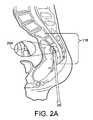
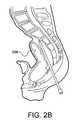
- FIG. 2illustrates an anterior axial trans-sacral access method of creating an axial channel in the spine which can be used to prepare an axial channel in the spine for use with the present invention.
- FIG. 3illustrates an implanted motion preservation assembly 300 in a spinal motion segment.
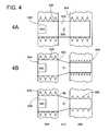
- FIG. 4is a series of drawings describing situations with a dual anchor rod implanted in a motion segment.
- FIG. 5illustrates a situation where driving the proximal component will not rotate the distal component.
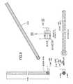
- FIG. 6shows a dual anchor driver assembly with an elongated polygonal torque driver.
- FIG. 7shows the complete dual anchor driver assembly of FIG. 6 .
- FIGS. 8-16provide details on components within the dual anchor driver assembly of FIGS. 6-7 .
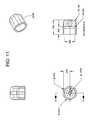
- FIG. 17shows a dual hex head driver with apertures.
- FIG. 18shows an exploded diagram and a loaded driver assembly with a dual hex head driver.
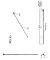
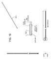
- FIG. 19shows the cross section of a keyed driver assembly for delivery of two implanted components.
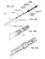
- FIG. 20shows a perspective view with a quarter round removed from a distractor/injector tool.
- FIG. 21is a flow chart describing a particular method for deployment of a motion preservation assembly.
- the present inventioncontemplates the use of the axial trans-sacral access to the lumbo-sacral spine.
- the axial trans-sacral access method illustrated in FIG. 2eliminates the need for muscular dissection and other invasive steps associated with traditional spinal surgery while allowing for the design and deployment of new and improved instruments and therapeutic interventions, including stabilization, motion preservation, and fixation devices/fusion systems across a progression-of-treatment in intervention.
- FIG. 2provides an introductory overview of the process with FIGS. 2A and 2B showing the process of “walking” a blunt tip stylet 204 up the anterior face of the sacrum 116 to the desired position on the sacrum 116 while monitored on a fluoroscope (not shown). This process moves the rectum 208 out of the way so that a straight path is established for the subsequent steps.
- FIG. 2Cillustrates a representative axial trans-sacral channel 212 established through the sacrum 116 , the L5/sacrum intervertebral space, the L5 vertebra 216 , the L4/L5 intervertebral space, and into the L4 vertebra 220 . If therapy is not being provided to the L4/L5 motion segment then the channel would end in L5 rather than extend into L4.
- FIG. 2The discussion of FIG. 2 is provided to provide context for the present invention.
- Previous applications(some now issued as United States patents) assigned to TranS1, Inc. have included a description of an alternative access method that is a posterior trans-sacral axial spinal approach rather than an anterior trans-sacral axial spinal approach.
- U.S. Pat. No. 6,558,386for Axial Spinal Implant and Method and Apparatus for Implanting an Axial Spinal Implant Within the Vertebrae of the Spine as this patent describes the anterior trans-sacral axial approach illustrated in FIG. 2 and is incorporated by reference in its entirety.
- the teachings of the present inventioncan be utilized with an axial trans-sacral channel.
- FIG. 2AA brief overview of this method of accessing the spinal region to receive therapy is useful to provide context for the present invention.
- a pre-sacral approachthrough percutaneous anterior track towards sacral target, through which trans-sacral axial bore will be made and channel extended distally for subsequent advancement of multi-level axial spinal stabilization assemblies.
- An anterior, pre-sacral, percutaneous tractextends through the “pre-sacral space” anterior to the sacrum.
- the pre-sacral, percutaneous tractis preferably used to introduce instrumentation to access and prepare (e.g., by drilling a bore in the distal/cephalad direction through one or more lumbar vertebral bodies and intervening discs).
- percutaneousin this context simply means through the skin and to the posterior or anterior target point, as in transcutaneous or transdermal, without implying any particular procedure from other medical arts.
- percutaneousis distinct from a surgical access, and the percutaneous opening in the skin is preferably minimized so that it is less than 4 cm across, preferably less than 2 cm, and, in certain applications, less than 1 cm across.
- the percutaneous pathwayis generally axially aligned with the bore extending from the respective anterior or posterior target point through at least one sacral vertebral body and one or more lumbar vertebral body in the cephalad direction as visualized by radiographic or fluoroscopic equipment. More specifically, as shown in FIG.
- the lumbar spineis accessed via a small skin puncture adjacent to the tip of the coccyx bone.
- the pre-sacral spaceis entered, using standard percutaneous technique, and the introducer assembly with the stylet's blunt tip serving as a dilator is placed through the paracoccygeal entry site.
- the blunt tipis rotated back against the anterior face of the sacrum and “walked” to the desired position on the sacrum under fluoroscopic guidance.
- the blunt-tipped styletis removed and a guide pin, or wire, is safely introduced through the guide pin introducer tube, and “tapped in”.
- the guide pinestablishes the trajectory for placement of subsequent bone dilators and sheath through which a twist drill is introduced creating an axial bore track, the lumen of which is extended distally.
- the guide pinmaintains the axial alignment of access & preparation tools as well as the alignment of cannulated spinal stabilization devices and assemblies, of larger diameter than the bore track, that are subsequently introduced over a 23′′ long, 0.090′′ diameter guide pin and through an exchange cannula for deployment of within the vertebral column, as described at least in part in co-pending and commonly assigned U.S. patent application Ser. Nos.
- FIG. 3illustrates an implanted motion preservation assembly 300 .
- This motion preservation assembly 300is implanted into a distal vertebral body 304 and a proximal vertebral body 308 and extends across an intervertebral disc space 312 .
- the motion preservation assembly 300would be placed in a previously prepared axial channel 212 .
- the distal vertebral body 304 , the proximal vertebral body 308 and the intervertebral disc space 312form a motion segment 316 .
- the drawings of the vertebral bodiesare not intended to convey anatomical details of the spinal components but to illustrate the placement of the assembled motion preservation assembly 300 .
- the motion segmentcould be more cephalad (and thus more distal to the surgeon) such as the L4/L5 vertebral bodies 220 , 216 (See FIG. 2 ).
- the major components of the motion preservation assembly 300include the distal component (anchored in the superior, or distal vertebral body, herein also sometimes referred to as distal bone anchor) 340 , proximal component (anchored in the inferior, or proximal vertebral body, herein also sometimes referred to as proximal bone anchor) 344 , prosthetic nucleus 348 (generally including outer membrane 460 ), and a pivot 352 .
- the outer membranecan be comprised of an elastomeric material, e.g. silicone rubber, such as that obtained from Nusil Silicone Technology located in Carpeneria, Calif., exhibiting elongation of between about 500% and about 1500% and most preferably about 1000% and having a wall thickness of 0.220 inches.
- the distal bone anchor 340 shown in FIG. 3has a set of external threads 356 .
- the set of external threads 356can include a chip breaker section 360 at the distal end of the distal bone anchor to facilitate the starting of cutting a thread path into the distal vertebral body 304 .
- a chip breakeris a discontinuity in the thread that allows chips to break off as the thread path is cut.
- the axial channel 212is created into the distal vertebral body 304 , with the diameter of the axial channel 212 at the distal vertebral body 304 approximately equal to the minor diameter of the set of external threads 356 .
- the distal bone anchor 340has a cavity 364 running from the distal face 366 of the distal bone anchor 340 to the proximal face 370 of the distal bone anchor 340 .
- a faceis the three dimensional surface of the part as viewed from that side, akin to the six three dimensional faces of die from a pair of dice.
- the cavity 364is not of uniform cross section and serves several purposes.
- the distal end of the cavity 364illustrates that the cavity can be used to allow the distal bone anchor 340 to be deployed over a guide wire.
- the cavity 364includes an internal threaded section 368 which can be engaged by a driver, retention or extraction tool as described below.
- the cavity 364 in the distal bone anchor 340 shown in FIG. 3contains a distal pivot cup 372 in a corresponding cup section 376 of the cavity 364 .
- the distal pivot cup 372in turn has a cavity 380 which serves as a bearing surface for the distal end 384 of the pivot 352 .
- the pivot 352 shown in FIG. 3has the distal end 384 referenced above and a proximal end 388 which in this embodiment are configured as substantially spherical components integral with the pivot body 392 .
- the proximal bone anchor 344has a set of external threads 404 including a lead-in section 408 .
- the proximal bone anchor 344has a cavity 412 that runs from the distal face 410 of the proximal bone anchor 344 to the proximal face 414 of the proximal bone anchor 344 .
- the cavity 412is not uniform in cross section.
- a portion of the cavity 412has a set of internal threads 416 .
- the pitch of the set of internal thread 416will be relatively fine (perhaps 16 threads per inch up to 64 threads per inch). In the particular motion preservation assembly shown in FIG.
- the proximal bone anchor cavity 412contains a proximal pivot cup 420 that has a set of external threads 424 that engage with the set of internal threads 416 to allow torque from a driver (not shown) imparted to a driver engagement section 428 to rotate the proximal pivot cup 420 relative to the proximal bone anchor 344 to axially (distally) advance the proximal pivot cup 420 .
- a drivernot shown
- a driver engagement section 428to rotate the proximal pivot cup 420 relative to the proximal bone anchor 344 to axially (distally) advance the proximal pivot cup 420 .
- axially advancing the proximal pivot cup 420will cause the proximal pivot cup 420 to contact the pivot 352 and cause the pivot 352 to contact the distal pivot cup 372 .
- proximal pivot cup 420After these components are in contact, further axial advancement of the proximal pivot cup 420 will cause the axial movement of the distal bone anchor 340 (and the distal vertebral body 304 engaged with the distal bone anchor 340 ) relative to the proximal bone anchor 344 (and the proximal vertebral body 308 engaged with the proximal bone anchor 344 ). This movement of one vertebral body away from another vertebral body causes a distraction of the intervertebral disc space between the two vertebral bodies.
- the distraction that can be achieved by rotation of the proximal pivot cup 420is preferably used as an adjustment to alter the distribution of loading between the pivot and the prosthetic nucleus component of the motion preservation assembly.
- the primary means for achieving distractionis by means of the distraction and insertion tool as will be described below.
- the driver engagement section 428could be configured among any one of many types of ways to impart torque with a driver.
- a female hex socketis a suitable choice.
- the proximal pivot cup 420 shown in FIG. 3includes a threaded cavity 432 which can be engaged with a driver or extraction tool.
- the proximal pivot cup 420includes a distal cavity 436 that serves as a bearing surface for the proximal end 388 of the pivot 352 .
- the cavity 412 in the proximal bone anchor 344also includes a jam nut 440 with a distal end 442 and a proximal end 446 .
- the jam nut 440has set of external threads 444 adapted to engage with the set of internal threads.
- the jam nut 440also has a driver engagement section 448 that is adapted to receive torque imparted by a corresponding driver such as a male hex driver. The torque input can cause the jam nut 440 to axially (distally) advance until it makes contact with the proximal pivot cup 420 .
- the jam nut 440 shown in FIG. 3also includes a threaded cavity 452 which can be used by a driver or extraction tool.
- the prosthetic nucleus 348includes an outer membrane 460 and prosthetic nucleus material 464 .
- outer membrane 460is filled with prosthetic nucleus material 464 , the outer membrane 460 expands to conformably contact the inferior endplate of the distal vertebral body 304 , the superior endplate of the proximal vertebral body 308 , and the inner wall of the annulus fibrosus (not shown) which collectively define the boundaries of an intervertebral disc space 312 .
- Preferred prosthetic nucleus materials and systemscomprise biomedical grade silicone elastomer e.g. silicone rubber, such as that obtained from Nusil Silicone Technology located in Carpeneria, Calif. or hydrogels or blends thereof (e.g., hydrogel/hydrogel, or hydrogel/elastomer).
- Cross-linked hyaluronic acidsuch as is available from Fidia Corporation in Italy, is an example of a suitable material, however, many natural and man-made hydrogels or blends thereof may be configured to achieve similar properties without inflammatory response, such as those disclosed and described in and commonly assigned United States patent applications referenced above, and in detail in particular in U.S. Provisional Patent Application 60/599,989 filed Aug. 9, 2004, and 60/558,069 filed Mar. 31, 2004, each of which are incorporated in their entirety into this disclosure by reference
- a threaded rod with a distal threaded section of a first, finer thread pitchengages with a distal vertebral body (after passing through a bore in the proximal vertebral body larger than the major diameter of the threads on the distal threaded section) and a proximal, coarser threaded section on the same threaded rod engages with a proximal vertebral body
- the rotation of the two threaded sections with different thread pitchescauses the distal finer pitched threads to advance into the distal vertebral body slower than the coarser threads advance into the proximal vertebral body.
- the net effectis that the engagement of the two threaded sections with the two vertebral bodies causes the two vertebral bodies to move apart.
- implant componentssuch as distal bone anchor 340 and proximal bone anchor 344 shown in FIG. 3 are much more than bone anchors but they do serve the function of anchoring the spinal implant assembly into vertebral bodies.
- the distal vertebral bodyis bored through to create a bore hole approximately the size of the proximal bone anchor 344 less the external threads 404 , or in other words approximately the size of the minor diameter of the external threads 404 of the proximal bone anchor 344 .
- the axial channel 212is extended at least partway into the distal vertebral body 304 and the bore size is approximately the size of the minor diameter of the external threads 356 on the distal bone anchor 340 .
- the minor diameters of both these sets of external threadsare the same.
- the major diameter of the external threads of the distal bone anchoris less than the minor diameter of the external threads on the proximal bone anchor so that the distal bone anchor can pass through the bore in the proximal vertebral body without leaving a helical thread cut in the proximal vertebral body.
- FIG. 4illustrates the various combinations of thread and bore sizes starting with a single rod with two threaded sections, one for the distal vertebral body and one for the proximal vertebral body.
- FIG. 4serves to introduce and illustrate concepts relevant to the present invention and is not intended to convey specific dimensional proportions.
- FIG. 4shows a series of proximal vertebral bodies 604 and distal vertebral bodies 608 with intervertebral disc spaces 612 located between the two vertebral bodies. Each pair of vertebral bodies as a dual anchor rod implanted.
- FIG. 4Ashows a dual anchor rod 620 with two threaded sections of the same diameter and pitch. As the threads 624 for the distal vertebral body 608 were driven through the proximal vertebral body 604 , a helical thread path was cut into the proximal vertebral body 604 .
- threads 628When the leading portion of threads 628 reach the proximal vertebral body 604 , it is preferable that these threads 628 use the same helical thread path previously cut by the threads 624 . Failure to do so results in cross threading which either makes it difficult to drive the dual anchor rod 620 or results in cutting new helical path into the proximal vertebral body which means that the vertebral body has undergone more mechanical damage than necessary (or both happen). Avoidance of cross threading is not difficult in this situation as the pitch of the threads 624 is the same as the pitch of the thread 628 so that the two sets of threads can be placed relative to one another as if it was one continuous set of threads.
- Waist section 632lies between the two threaded sections and in particular, is located in the intervertebral disc space 612 .
- the waist section 632can include apertures 636 in fluid communication with a central cavity in the dual anchor rod 620 so that therapeutic materials such as bone paste used in fusion therapy can be delivered.
- a single driver engagement section 640such as a female hex socket can be engaged with a corresponding driver to rotate, axially advance, and implant the dual anchor rod 620 into engagement with both the proximal vertebral body 604 and the distal vertebral body 608 .
- FIG. 4Bshows a dual anchor rod 644 where the set of threads 648 for engagement with the distal vertebral body 608 , have a major diameter that is slightly less than the minor diameter of the set of threads 628 so that the set of thread 648 do not cut a spiral thread cut into the proximal vertebral body 604 as these threads are axially advanced towards a bore in the distal vertebral body 608 .
- the dual anchor rod 644has a single driver engagement section 640 which rotates both sets of threads 628 and 648 as these sections are connected by waist 652 .
- the use of threads with a finer pitch in the distal vertebral body 608 and threads of a coarser pitch in the proximal vertebral body 604imposes a distraction to increase the distance between the proximal vertebral body 604 and the distal vertebral body 608 to increase the size of the intervertebral disc space 612 .
- the decrease in major diameter between thread set 628 and thread set 648has the disadvantage of decreasing the amount of interaction between the thread set 648 and the distal vertebral body 608 .
- This decrease in major diameteris necessary when the pitches are not the same in order to avoid creating a helical thread path that the subsequent thread set 628 would be unable to follow due to the difference in thread pitch.
- FIG. 4Cis not commonly found as having a dual anchor rod 656 with thread sections 628 and 660 with different major diameters but the same thread pitch connected by waist 664 does not have the advantages of either dual anchor rod 620 or dual anchor rod 644 .
- Some spinal implant assembliesincluding spinal implant assemblies disclosed in and commonly assigned U.S. patent Ser. No. 11/256,810 filed Oct. 24, 2005 for Spinal Motion Preservation Assemblies (incorporated by reference herein) disclose assemblies where the component that is implanted in the distal vertebral body 608 is not rigidly connected to the component implanted in the proximal vertebral body 604 .
- the two componentsmay be connected at point of implantation into the vertebral bodies by a flexible membrane 460 (See FIG. 3 ) that will be expanded with injected prosthetic nucleus material to form a prosthetic nucleus 348 ( FIG. 3 ), however, the connection afforded by the flexible membrane 460 is not sufficiently rigid to control the relative positions of the two separate components.
- FIG. 3See FIG. 3
- FIG. 5Aillustrates that when using a distal component 816 and a proximal component 820 with the external thread sets 824 and 828 having the same major diameter and pitch, a driver engaged with driver engagement section 832 cannot impart torque to the distal component 816 .
- a driver engaged with driver engagement section 832cannot impart torque to the distal component 816 .
- the previous applications and issued patents for assignee, TranS1 Inc.include teachings regarding the formation of a prosthetic nucleus using an injected barrier sealant material to seal the interior surfaces of the intervertebral disc space before injection prosthetic nucleus material.
- Components delivered as part of the process of a therapy using a barrier sealant material in lieu of a flexible membranewould, by definition, not be connected by a flexible membrane.
- FIG. 5Billustrates the case where distraction of the motion segment is desired and the chosen method of distraction is the use of dissimilar thread pitches between the thread set 848 on the distal component 836 and thread set 828 on the proximal component 820 . Again there is a need to impart torque to not only a driver engagement section 820 on proximal component 820 but also to convey torque to distal component 836 .
- FIG. 5Cis offered for completeness, but it will be less common to use two separate components 856 and 862 that have different major diameters for their thread sets but have the same thread pitch.
- the prior artdid not provide a suitable solution for use in the axial delivery of two components to two adjacent vertebral bodies nor did the prior art provide a suitable solution for the process of axial delivery of two components to two adjacent vertebral bodies combined with an imposed distraction of the vertebral bodies to be maintained by the insertion of prosthetic nucleus material.
- FIG. 6Ashows an enlarged portion of a loaded dual anchor driver assembly 2100 in a perspective view with a quarter round removed to expose the interaction of components.
- the dual anchor driver assembly 2100uses a polygonal torque driver 2104 to simultaneously engage a distal bone anchor 2108 and a proximal bone anchor 2112 .
- These bone anchorshave external threaded sections ( 2116 and 2120 ) that have the same minor diameter, the same major diameter, the same pitch, and the same handedness.
- the delivery of the two bone anchorsmust be timed. Having control over the relative position of the bone anchors during the rotation and axial advancement of the bone anchors makes this possible.
- controlis provided by A) the action of retention rod 2012 engaging with internal threads 2124 of distal anchor 2108 to pull the distal anchor 2108 to seat it on the distal tip 2128 of the polygonal torque driver 2104 and B) the action of proximal anchor retention coupler 2132 engaging a set of external threads 2136 with internal threads 2142 of proximal anchor 2112 to seat the proximal anchor 2112 on a shoulder 2146 polygonal torque driver 2104 .
- Both retention rod 2012 and proximal anchor retention coupler 2132are connected to dual anchor driver 2100 such that each can rotate relative to the polygonal torque driver 2104 .
- FIG. 6Bshows a cross section of the dual anchor driver 2100 including shoulder 2138 of the polygonal torque driver 2104 that contacts the proximal anchor 2112 and shows the engagement of the flange 2130 with the other components in the dual anchor driver assembly 2100 .
- hexagonal polygonis commonly used as a torque driver
- other polygonscould be used such as triangular, square, pentagonal, octagonal and so on. More complex shapes such as stars or non symmetric shapes could be used but a simple polygon is adequate.
- FIG. 7shows dual anchor driver assembly 2100 with handle 2204 .
- Rotating the handlerotates the driver shaft 2216 including the polygonal torque driver 2104 .
- the distal component 2108can be threadedly engaged by rotation of thread on retention rod 2012 by rotating the retention rod knob 2208 . This causes the retention rod to rotate relative to the polygonal torque driver 2014 .
- Rotation of external sheath 2212causes threaded engagement by external threads 2036 on proximal anchor retention coupler 2032 with corresponding threads on the proximal anchor.
- the sheath 2211 and attached proximal anchor retention coupler 2032can rotate relative to the polygonal torque driver 2104 .
- Retention pins 2220retain the proximal anchor coupler 2032 to the sheath 2212 .
- FIGS. 8-16A set of detailed drawings of the various components that comprise a dual anchor driver 2100 of the type shown in FIG. 7 are provided in FIGS. 8-16 and should be self-explanatory of those of skill in the art. (Detailed drawings not provided of retainer pins as these details should be discernable from the other drawings).
- polygonal torque driver 2104has a hollow cavity 2224 running along its longitudinal axis which is used by the retention rod 2012 .
- This same cavity 2224could be connected through apertures (not shown) to deliver flowable material between the distal component 2108 and the proximal component 2112 into the intervertebral disc space.
- a variety of biomaterialscan be delivered. Examples include curable elastomers, hydrogels, and blends of elastomers and hydrogels.
- the cavity 364 in the distal end of the distal componentis open to allow a loaded driver assembly to be deployed over a guide wire, this should not present a problem while injecting material.
- the opening to the cavity 364will often be contained within the distal vertebral body (See FIG. 3 ).
- the retention rod or some other delivery devicecould be used to deliver a plug to this cavity 364 after it has served its purpose with respect to the guide wire.
- FIG. 17shows an alternative torque driver 2230 with apertures 2234 .
- a dual hex head driver 2230 of this typeis adapted for use when the cross section of the distal component is reduced relative to the cross section of the proximal component such as illustrated in FIG. 5B , typically when dissimilar thread pitch is being used to provide distraction.
- a driver assembly using the dual hex head driver 2230can be left in place, that is with the driver maintaining the relative position of the two components as one component is held by engagement with the distal portion of the dual hex head driver 2230 by the retention rod and the other component is held in engagement with a more proximal portion of the dual hex head driver by the coupling.
- FIG. 18Aprovides an exploded diagram showing the use of an O-Ring to help limit the undesired flow of injected material into the driver assembly.
- FIGS. 18B and 18Cillustrate other details of the interaction between the dual hex head driver and other system components.
- a dual hex head driveris a descriptive name for the driver shown in FIGS. 17 and 18 but one of skill in the art will recognize that other polygonal shapes are viable.
- the dual hex head driver and the polygonal torque driver described in connection with Example Acan be manufactured in a variety of lengths so that the drivers can maintain the distal and proximal components at relative axial distances that are appropriate for both timed delivery of the proximal component (if timed delivery is used to avoid cross threading) and to adjust to the variations in anatomy between patients and the desired level of distraction.
- FIG. 19shows a distal bone anchor 1340 and a proximal bone anchor 1344 with a membrane 460 connected to the distal bone anchor 1340 and the proximal bone anchor 1344 .
- the thread pitch of the external threads 356 on the distal bone anchorare the same as the thread pitch on the set of external threads 404 on the proximal bone anchor.
- the keyed driver assembly 2000has a key 2004 with a shoulder 2008 . The key 2004 slides in the slots in the proximal bone anchor and the distal bone anchor (previously discussed). The keyed driver assembly 2000 thus prevents the proximal bone anchor 1344 from rotating relative to the distal bone anchor 1340 .
- a retention rod 2012 with external thread 2016engages with the internal threaded section 368 of the distal bone anchor 1340 .
- the retention rod 2012can be rotated relative to the driver tip 2018 so that the distal bone anchor 1340 is pulled to contact the driver tip 2018 .
- a proximal anchor retention coupler 2088 with external threads 2092can rotate relative to the driver tip 2018 as the proximal anchor retention coupler 2088 is attached to an external sheath 2096 .
- Rotation of the proximal anchor retention coupler 2088causes engagement between the external threads 2092 and the internal threads 416 of the proximal anchor 1344 to draw the proximal anchor 1344 down onto the shoulder 2008 .
- the position of the distal bone anchor 1340 relative to the proximal bone anchor 1344can be set based on the distances between the shoulder 2008 and the driver tip 2018 . Control over the distances between the two separate bone anchors allows the two bone anchors with the same major diameter to be inserted without cross threading of the proximal vertebral body.
- FIG. 20show the use of a distractor/injector that is used after the components have been implanted in the proximal and distal vertebral bodies and the implant driver removed.
- This type of distractor/injectoris useful when additional components need to be inserted into the distal bone anchor 340 before the injection of prosthetic nucleus material.
- a distal pivot cup 372that will serve as the bearing surface for a pivot (not shown here but see FIG. 3 ) has been inserted in an implanted distal bone anchor.
- the bone anchorscould be implanted with an driver assembly of the type discussed in Example A and FIG. 6 , or if the distal and proximal components had a slot for keyed delivery, a driver assembly of the type discussed in connection FIG. 19 could be used.
- FIG. 20shows a distraction and insertion tool 2032 used to distract the motion segment then deploy prosthetic nucleus material in to the membrane 460 to distend the membrane 460 to a conforming fit within the space of the intervertebral disc space.
- the insertion tool 2032has a set of external threads 2036 which engage with a set of internal threads 416 in the proximal bone anchor 344 .
- the distal end of the insertion tool 2032is an atraumatic tip 2042 designed to contact without damaging the bearing surface in the distal pivot cup 372 .
- Axially advancing the distraction and insertion tool 2032pushes the atraumatic tip 2042 on the distal pivot cup 372 to move the vertebral body engaged with the distal bone anchor 340 relative to the vertebral body engaged with the proximal bone anchor 344 .
- an internal channel 2048is used to provide prosthetic nucleus material to be delivered through a set of fenestrations 2052 to fill and expand the membrane 460 .
- the prosthetic nucleus materialis inserted until there is a conforming fit between the membrane 460 and the endplates of the two vertebral bodies and the wall of the annulus fibrosus.
- the insertion tool 2032can be removed leaving behind a void in the prosthetic nucleus material where the insertion tool was during the formation of the prosthetic nucleus. (see element 348 on FIG. 3 ).
- the process 3200 for using a driver to first implant the distal and proximal devices, then insert one or more components before inserting a different tool to distract and then inject prosthetic nucleus materialis summarized in FIG. 21 .
- Step 3210Load the device driver assembly with both the distal and proximal components. These two anchors, connected by a flexible membrane, are placed on the anchor driver assembly.
- the driver assemblyuses an elongated torque driver, in this case a hexagonal shaped toque driver with an elongated section with a constant cross sectional (taken perpendicular to the longitudinal axis).
- the step of loading the driver assemblyincludes seating the distal component onto the distal end of the driver wherein it is retained on the tip during insertion and axial, distal advancement by means of a threaded retention rod, and seating the proximal bone anchor on a shoulder within the dual anchor driver assembly through use of a proximal anchor retention coupler.
- Seating the two bone anchors on the driver assemblymaintains a predetermined spatial separation between the distal component and proximal component and stretches the flexible membrane located there between so that the membrane slightly “necks in” and is less likely to be damaged while passing through the proximal vertebral body.
- Step 3220Insert the anchor driver assembly over a guide wire and advance the anchor driver assembly through the previously prepared axial channel that includes a bore through the proximal vertebral body and a bore in the distal vertebral body.
- the bore hole in the proximal vertebral bodyis about the size of the minor diameter of the external threads on both bone anchors.
- Step 3230Torque is applied using the anchor driver assembly to rotate and axially advance the distal bone anchor through the proximal vertebral body thereby creating a helical thread path through the first vertebral body.
- Step 3240Continued application of torque axially advances the bone anchors, which are held on the anchor driver assembly at a spatially maintained distance, to anchor the distal component into the distal vertebral body and anchor the proximal component into the proximal vertebral body without cross threading or rethreading in the proximal vertebral body.
- Step 3250Once the bone anchors are positioned into the respective vertebral bodies, release the distal bone anchor from the threaded engagement with the retention rod and release the proximal bone anchor from the proximal anchor retention coupler as the retention rod and the proximal anchor retention coupler can be rotated relative to the elongated hexagonal hex driver.
- Step 3260Remove the anchor driver assembly.
- Step 3270Insert the distal pivot cup by engaging the distal pivot cup with driver (not shown here) that employs a detent mechanism to engage the distal pivot cup.
- drivernot shown here
- a detent mechanismto engage the distal pivot cup.
- Step 3280Disengage the distal pivot cup driver from the distal pivot cup and remove the distal pivot cup driver.
- Step 3290Insert distractor/injector tool into the implanted bone anchors so that atraumatic tip of the distractor/injector tool contacts the distal pivot cup bearing surface.
- the material selected for the atraumatic tipmay be advantageously selected to be less hard than the bearing surface and smooth so it is not apt to scratch the bearing surface.
- Step 3300Move the distal vertebral body relative to the proximal vertebral body by axially advancing the distractor/injector tool relative to the proximal bone anchor through threaded engagement within the proximal bone anchor to push via an atraumatic tip on the distal pivot cup.
- Step 3310Inject prosthetic nucleus material through the interior of the distractor/injector and out apertures in fluid communication between the interior of the distractor/injector and the flexible membrane to expand and fill the flexible membrane sufficiently to form the prosthetic nucleus component of this prosthetic disc device, the prosthetic nucleus component being in conformal contact with the surfaces of the intervertebral disc space.
- Step 3320Allow the injected material to cure.
- Step 3330Remove the distractor/injector tool. This will leave a void in the cured injected material where the tool occupied volume in the intervertebral disc space during injection and curing.
- the cured prosthetic nucleus materialshould substantially retain the distraction imposed between the vertebral bodies.
- Subsequent processing steps during assembly of the spinal implant assemblycould include a minor secondary distraction. Alternatively, the original distraction could be increased a small amount to compensate for any movement of cured injected material towards the void left by the removal of the distractor/injector.
- Preferred materials for the various components shown in the drivers described aboveinclude components that are formed, i.e., machined, from among high strength (e.g., high tensile strength, high fatigue strength), wear and abrasion resistant metal alloys (e.g., MP35N; ElgiloyTM, a super alloy of cobalt chrome; Co—Cr alloy such as StelliteTM; Ti6Al4V alloy, and nitride coated Ti alloys) according to the biomechanical properties being selected by design (e.g., ability of driver to withstand torque while rotating to axially advance dual anchor implants through and into vertebral bone).
- high strengthe.g., high tensile strength, high fatigue strength
- wear and abrasion resistant metal alloyse.g., MP35N; ElgiloyTM, a super alloy of cobalt chrome; Co—Cr alloy such as StelliteTM; Ti6Al4V alloy, and nitride coated Ti alloys
- designe.g
- the membraneis expanded by means of high pressure injection, with a syringe, of prosthetic nucleus material (PNM) (e.g., saline, viscoelastic gel or an elastomeric solid or blends or combinations thereof), that is engaged by means of an integral Luer lock fitting that is configured to engage the handle at the proximal end of the MPA distractor/injector.
- PPMprosthetic nucleus material
- a delivery tube or catheterwherein the distal end of the tube is configured to engage the fitting in proximal end of the tool, and the proximal end of the tube engages a syringe attached thereon.
- the expandable membraneis enlarged or filled by means of apertures or fenestrations, e.g., through the slits or “cuts” in the cannulated rod comprising the in the torque driver (such as the dual hex head driver discussed above) or the distractor/injector tool, which enable fluid communication between the exterior and interior of the driver of the and through which prosthetic nucleus material is injected into the disc space, either directly, or via an intermediate (from about 6-12 mm of the overall deployed implant length) expandable membrane configured to be adhesively affixed and engaged by laser welding of a retainer ring, to or into the distal end of the proximal threaded anchor component and the proximal end of the distal threaded anchor component, respectively.
- the expandable membraneinflates and extends into the intervertebral disc space previously distracted by means of the driver/injector or distractor/injector of the present invention, until when filled, it conformably contacts the surfaces within the intervertebral disc space.
- the ultimate expansion of the membraneis limited by contact with the end plates and the annulus, preventing rupture of the membrane due to over inflation.
- the MPAWhen filled and expanded in this manner with a suitable PNM, e.g., a hydrogel selected at least in part based on viscoelastic properties, the MPA is enabled to biomechanically perform the intended function of the motion restoration segment, e.g., the membrane, when filled with PNM, transfers hydrostatic pressure within the nuclear space into tensile “hoop stresses” in the annulus.
- a suitable PNMe.g., a hydrogel selected at least in part based on viscoelastic properties
- driver/injectors or distractor/injectorsare configured to accommodate injection means with sufficient pressure/forces of substantially about 300 psi to deliver the PNM (or therapeutic, e.g., drug materials delivery) without accompanying shear forces that would fragment; denaturate; modify viscoelastic properties, e.g., rheology and/or compressibility; or otherwise render the therapeutic materials or PNM ineffective for their intended functionality (e.g., biomechanical motion segment mobility restoration/preservation in the case of PND with PNM).
- driver/injectors or distractor/injectorscomprise at least one O-ring to enable injection of fluid(s) under pressure.
Landscapes
- Health & Medical Sciences (AREA)
- Orthopedic Medicine & Surgery (AREA)
- Life Sciences & Earth Sciences (AREA)
- Engineering & Computer Science (AREA)
- Biomedical Technology (AREA)
- Surgery (AREA)
- General Health & Medical Sciences (AREA)
- Public Health (AREA)
- Veterinary Medicine (AREA)
- Animal Behavior & Ethology (AREA)
- Heart & Thoracic Surgery (AREA)
- Neurology (AREA)
- Molecular Biology (AREA)
- Nuclear Medicine, Radiotherapy & Molecular Imaging (AREA)
- Medical Informatics (AREA)
- Transplantation (AREA)
- Cardiology (AREA)
- Oral & Maxillofacial Surgery (AREA)
- Vascular Medicine (AREA)
- Neurosurgery (AREA)
- Physical Education & Sports Medicine (AREA)
- Prostheses (AREA)
- Surgical Instruments (AREA)
Abstract
Description
Claims (35)
Priority Applications (19)
| Application Number | Priority Date | Filing Date | Title |
|---|---|---|---|
| US11/259,614US7938836B2 (en) | 2003-10-23 | 2005-10-25 | Driver assembly for simultaneous axial delivery of spinal implants |
| EP06826585AEP1945115A2 (en) | 2005-10-24 | 2006-10-24 | Methods and tools for delivery of spinal motion preservation assemblies |
| KR1020087012483AKR20080083265A (en) | 2005-10-24 | 2006-10-24 | Apparatus and method for delivery of spinal motion preservation assemblies |
| AU2006306225AAU2006306225A1 (en) | 2005-10-24 | 2006-10-24 | Spinal motion preservation assemblies |
| JP2008537887AJP2009512537A (en) | 2005-10-24 | 2006-10-24 | Spinal motion maintenance assembly |
| PCT/US2006/041535WO2007050640A2 (en) | 2005-10-24 | 2006-10-24 | Spinal motion preservation assemblies |
| US11/586,338US7776068B2 (en) | 2003-10-23 | 2006-10-24 | Spinal motion preservation assemblies |
| EP06826589AEP1945114A2 (en) | 2005-10-24 | 2006-10-24 | Spinal motion preservation assemblies |
| CA002627030ACA2627030A1 (en) | 2005-10-24 | 2006-10-24 | Spinal motion preservation assemblies |
| KR1020087012482AKR20080080505A (en) | 2005-10-24 | 2006-10-24 | Spinal Exercise Preservation Assembly |
| CA002627167ACA2627167A1 (en) | 2005-10-24 | 2006-10-24 | Methods and tools for delivery of spinal motion preservation assemblies |
| JP2008537890AJP2009512538A (en) | 2005-10-24 | 2006-10-24 | Spinal motion maintenance assembly |
| PCT/US2006/041522WO2007050629A2 (en) | 2005-10-24 | 2006-10-24 | Methods and tools for delivery of spinal motion preservation assemblies |
| US11/586,486US8038680B2 (en) | 2003-10-23 | 2006-10-24 | Drivers for inserts to bone anchors |
| AU2006306302AAU2006306302A1 (en) | 2005-10-24 | 2006-10-24 | Methods and tools for delivery of spinal motion preservation assemblies |
| US11/712,548US20070260270A1 (en) | 2000-02-16 | 2007-02-28 | Cutter for preparing intervertebral disc space |
| US11/712,241US7632274B2 (en) | 2000-02-16 | 2007-02-28 | Thin cutter blades with retaining film for preparing intervertebral disc spaces |
| IL191046AIL191046A0 (en) | 2005-10-24 | 2008-04-27 | Methods and tools for delivery of spinal motion preservation assemblies |
| IL191045AIL191045A0 (en) | 2005-10-24 | 2008-04-27 | Spinal motion preservation assemblies |
Applications Claiming Priority (12)
| Application Number | Priority Date | Filing Date | Title |
|---|---|---|---|
| US51389903P | 2003-10-23 | 2003-10-23 | |
| US55806904P | 2004-03-31 | 2004-03-31 | |
| US59998904P | 2004-08-09 | 2004-08-09 | |
| US62114804P | 2004-10-22 | 2004-10-22 | |
| US10/972,039US7491236B2 (en) | 2000-02-16 | 2004-10-22 | Dual anchor prosthetic nucleus apparatus |
| US10/972,176US7547324B2 (en) | 2000-02-16 | 2004-10-22 | Spinal mobility preservation apparatus having an expandable membrane |
| US10/972,184US7717958B2 (en) | 2000-02-16 | 2004-10-22 | Prosthetic nucleus apparatus |
| US10/972,040US7662173B2 (en) | 2000-02-16 | 2004-10-22 | Spinal mobility preservation apparatus |
| US62173004P | 2004-10-25 | 2004-10-25 | |
| US11/199,541US20060206209A1 (en) | 2003-10-23 | 2005-08-08 | Prosthetic nucleus apparatus and methods |
| US11/256,810US7601171B2 (en) | 2003-10-23 | 2005-10-24 | Spinal motion preservation assemblies |
| US11/259,614US7938836B2 (en) | 2003-10-23 | 2005-10-25 | Driver assembly for simultaneous axial delivery of spinal implants |
Related Parent Applications (3)
| Application Number | Title | Priority Date | Filing Date |
|---|---|---|---|
| US10/972,184Continuation-In-PartUS7717958B2 (en) | 2000-02-16 | 2004-10-22 | Prosthetic nucleus apparatus |
| US11/256,810Continuation-In-PartUS7601171B2 (en) | 2000-02-16 | 2005-10-24 | Spinal motion preservation assemblies |
| US11/586,486Continuation-In-PartUS8038680B2 (en) | 2000-02-16 | 2006-10-24 | Drivers for inserts to bone anchors |
Related Child Applications (2)
| Application Number | Title | Priority Date | Filing Date |
|---|---|---|---|
| US11/586,486Continuation-In-PartUS8038680B2 (en) | 2000-02-16 | 2006-10-24 | Drivers for inserts to bone anchors |
| US11/586,338Continuation-In-PartUS7776068B2 (en) | 2000-02-16 | 2006-10-24 | Spinal motion preservation assemblies |
Publications (2)
| Publication Number | Publication Date |
|---|---|
| US20060155297A1 US20060155297A1 (en) | 2006-07-13 |
| US7938836B2true US7938836B2 (en) | 2011-05-10 |
Family
ID=37968496
Family Applications (2)
| Application Number | Title | Priority Date | Filing Date |
|---|---|---|---|
| US11/259,614Active2029-01-22US7938836B2 (en) | 2000-02-16 | 2005-10-25 | Driver assembly for simultaneous axial delivery of spinal implants |
| US11/586,486Expired - Fee RelatedUS8038680B2 (en) | 2000-02-16 | 2006-10-24 | Drivers for inserts to bone anchors |
Family Applications After (1)
| Application Number | Title | Priority Date | Filing Date |
|---|---|---|---|
| US11/586,486Expired - Fee RelatedUS8038680B2 (en) | 2000-02-16 | 2006-10-24 | Drivers for inserts to bone anchors |
Country Status (8)
| Country | Link |
|---|---|
| US (2) | US7938836B2 (en) |
| EP (2) | EP1945115A2 (en) |
| JP (2) | JP2009512537A (en) |
| KR (2) | KR20080083265A (en) |
| AU (2) | AU2006306302A1 (en) |
| CA (2) | CA2627167A1 (en) |
| IL (2) | IL191045A0 (en) |
| WO (2) | WO2007050629A2 (en) |
Cited By (35)
| Publication number | Priority date | Publication date | Assignee | Title |
|---|---|---|---|---|
| US20090138053A1 (en)* | 2007-09-25 | 2009-05-28 | Zyga Technology, Inc. | Method and apparatus for facet joint stabilization |
| US8394125B2 (en) | 2009-07-24 | 2013-03-12 | Zyga Technology, Inc. | Systems and methods for facet joint treatment |
| US8663293B2 (en) | 2010-06-15 | 2014-03-04 | Zyga Technology, Inc. | Systems and methods for facet joint treatment |
| US8696707B2 (en) | 2005-03-08 | 2014-04-15 | Zyga Technology, Inc. | Facet joint stabilization |
| US20140114365A1 (en)* | 2005-05-10 | 2014-04-24 | Acumed Llc | Bone connector with pivotable joint |
| US9138219B2 (en) | 2010-12-29 | 2015-09-22 | Tarsus Medical Inc. | Methods and devices for treating a syndesmosis injury |
| US9186484B2 (en) | 2010-07-01 | 2015-11-17 | DePuy Synthes Products, Inc. | Guidewire insertion methods and devices |
| US20150327902A1 (en)* | 2014-05-16 | 2015-11-19 | Biomet C.V. | Method and apparatus for bone fixation |
| US9233006B2 (en) | 2010-06-15 | 2016-01-12 | Zyga Technology, Inc. | Systems and methods for facet joint treatment |
| US9289249B2 (en) | 2013-03-14 | 2016-03-22 | DePuy Synthes Products, Inc. | Bone anchors and surgical instruments with integrated guide tips |
| US9532884B2 (en) | 2011-07-14 | 2017-01-03 | Nlt Spine Ltd. | Laterally deflectable implant |
| US9833328B2 (en) | 2010-06-15 | 2017-12-05 | Zyga Technology | System and methods for facet joint treatment |
| US9855087B2 (en) | 2014-08-04 | 2018-01-02 | DePuy Synthes Products, LLC | Methods and devices for spinal screw insertion |
| US20180116814A1 (en)* | 2016-10-31 | 2018-05-03 | Warsaw Orthopedic, Inc | Sacro-iliac joint implant system and method |
| US10349982B2 (en) | 2011-11-01 | 2019-07-16 | Nuvasive Specialized Orthopedics, Inc. | Adjustable magnetic devices and methods of using same |
| US10433883B2 (en) | 2017-06-27 | 2019-10-08 | Medos International Sarl | Spinal screw insertion devices and methods |
| US10478232B2 (en) | 2009-04-29 | 2019-11-19 | Nuvasive Specialized Orthopedics, Inc. | Interspinous process device and method |
| US10617453B2 (en) | 2015-10-16 | 2020-04-14 | Nuvasive Specialized Orthopedics, Inc. | Adjustable devices for treating arthritis of the knee |
| US10646262B2 (en) | 2011-02-14 | 2020-05-12 | Nuvasive Specialized Orthopedics, Inc. | System and method for altering rotational alignment of bone sections |
| US10660675B2 (en) | 2010-06-30 | 2020-05-26 | Nuvasive Specialized Orthopedics, Inc. | External adjustment device for distraction device |
| US10729470B2 (en) | 2008-11-10 | 2020-08-04 | Nuvasive Specialized Orthopedics, Inc. | External adjustment device for distraction device |
| US10743794B2 (en) | 2011-10-04 | 2020-08-18 | Nuvasive Specialized Orthopedics, Inc. | Devices and methods for non-invasive implant length sensing |
| US10751094B2 (en) | 2013-10-10 | 2020-08-25 | Nuvasive Specialized Orthopedics, Inc. | Adjustable spinal implant |
| US10779872B2 (en) | 2017-11-02 | 2020-09-22 | Medos International Sarl | Bone anchor insertion instruments and methods |
| US10835290B2 (en) | 2015-12-10 | 2020-11-17 | Nuvasive Specialized Orthopedics, Inc. | External adjustment device for distraction device |
| US10918425B2 (en) | 2016-01-28 | 2021-02-16 | Nuvasive Specialized Orthopedics, Inc. | System and methods for bone transport |
| US11123113B2 (en) | 2019-06-13 | 2021-09-21 | Medos International Sarl | Screw inserter instruments and methods |
| US11191579B2 (en) | 2012-10-29 | 2021-12-07 | Nuvasive Specialized Orthopedics, Inc. | Adjustable devices for treating arthritis of the knee |
| US11202707B2 (en) | 2008-03-25 | 2021-12-21 | Nuvasive Specialized Orthopedics, Inc. | Adjustable implant system |
| US11224472B2 (en) | 2019-06-13 | 2022-01-18 | Medos International Sarl | Screw inserter instruments and methods |
| US11234849B2 (en) | 2006-10-20 | 2022-02-01 | Nuvasive Specialized Orthopedics, Inc. | Adjustable implant and method of use |
| US11246694B2 (en) | 2014-04-28 | 2022-02-15 | Nuvasive Specialized Orthopedics, Inc. | System for informational magnetic feedback in adjustable implants |
| US11357549B2 (en) | 2004-07-02 | 2022-06-14 | Nuvasive Specialized Orthopedics, Inc. | Expandable rod system to treat scoliosis and method of using the same |
| US11439449B2 (en) | 2014-12-26 | 2022-09-13 | Nuvasive Specialized Orthopedics, Inc. | Systems and methods for distraction |
| US11612416B2 (en) | 2015-02-19 | 2023-03-28 | Nuvasive Specialized Orthopedics, Inc. | Systems and methods for vertebral adjustment |
Families Citing this family (55)
| Publication number | Priority date | Publication date | Assignee | Title |
|---|---|---|---|---|
| WO2007084649A2 (en)* | 2006-01-17 | 2007-07-26 | Highgate Orthopedics, Inc. | Systems, devices and apparatuses for bony fixation and disk repair and replacement and methods related thereto |
| US20050267481A1 (en) | 2003-10-17 | 2005-12-01 | Allen Carl | Systems, devices and apparatuses for bony fixation and disk repair and replacement and methods related thereto |
| US7641657B2 (en) | 2003-06-10 | 2010-01-05 | Trans1, Inc. | Method and apparatus for providing posterior or anterior trans-sacral access to spinal vertebrae |
| US7717958B2 (en) | 2000-02-16 | 2010-05-18 | Trans1, Inc. | Prosthetic nucleus apparatus |
| US7014633B2 (en) | 2000-02-16 | 2006-03-21 | Trans1, Inc. | Methods of performing procedures in the spine |
| US6740090B1 (en) | 2000-02-16 | 2004-05-25 | Trans1 Inc. | Methods and apparatus for forming shaped axial bores through spinal vertebrae |
| US7744599B2 (en) | 2000-02-16 | 2010-06-29 | Trans1 Inc. | Articulating spinal implant |
| DK1578315T3 (en) | 2000-02-16 | 2008-10-06 | Trans1 Inc | Device for vertebral column distribution and fusion |
| US6558390B2 (en) | 2000-02-16 | 2003-05-06 | Axiamed, Inc. | Methods and apparatus for performing therapeutic procedures in the spine |
| US8828067B2 (en)* | 2001-10-18 | 2014-09-09 | Orthoip, Llc | Bone screw system and method |
| US9060809B2 (en) | 2001-10-18 | 2015-06-23 | Orthoip, Llc | Lagwire system and method for the fixation of bone fractures |
| US7955388B2 (en)* | 2006-11-01 | 2011-06-07 | Acumed Llc | Orthopedic connector system |
| WO2007079242A2 (en) | 2005-12-29 | 2007-07-12 | Highgate Orthopedics, Inc. | Devices and methods for bony fixation and disk repair and replaceme |
| AU2004283727A1 (en) | 2003-10-23 | 2005-05-06 | Trans1 Inc. | Tools and tool kits for performing minimally invasive procedures on the spine |
| US7637927B2 (en)* | 2004-03-25 | 2009-12-29 | Hyde Jr Edward R | Transosseous spine core approach method implant and instrumentation |
| JP2008508980A (en)* | 2004-08-09 | 2008-03-27 | トランス1,インク. | Nucleus nucleus prosthesis device and method |
| US20100016889A1 (en)* | 2006-06-13 | 2010-01-21 | Anova Corporation | Methods and apparatus for anulus repair |
| US8834496B2 (en) | 2006-06-13 | 2014-09-16 | Bret A. Ferree | Soft tissue repair methods and apparatus |
| US8821549B2 (en) | 2006-06-13 | 2014-09-02 | Anova Corporation | Methods and apparatus for anulus repair |
| US9232938B2 (en) | 2006-06-13 | 2016-01-12 | Anova Corp. | Method and apparatus for closing fissures in the annulus fibrosus |
| US8764835B2 (en) | 2006-06-13 | 2014-07-01 | Bret A. Ferree | Intervertebral disc treatment methods and apparatus |
| US8088147B2 (en)* | 2006-10-24 | 2012-01-03 | Trans1 Inc. | Multi-membrane prosthetic nucleus |
| US20100179573A1 (en)* | 2006-10-31 | 2010-07-15 | Core Essence Orthopaedics, Llc | Medical device and procedure for attaching tissue to bone |
| US20090275993A1 (en)* | 2008-04-30 | 2009-11-05 | Phan Christopher U | Apparatus and methods for inserting facet screws |
| US20100312251A1 (en)* | 2009-06-03 | 2010-12-09 | Fraser Landreneau | Pedicle Driver |
| US8747472B2 (en)* | 2009-08-14 | 2014-06-10 | Baxano Surgical, Inc. | Spinal therapy device with fixated distraction distance |
| FR2968535B1 (en)* | 2010-12-13 | 2012-12-28 | D L P Sarl | SURGICAL INSTRUMENT FOR A TECHNIQUE FOR ATTACHING BONE FRAGMENTS USING CANULATED SCREW |
| JP4995978B2 (en)* | 2011-03-15 | 2012-08-08 | 宏美 林 | Treatment method of living body excluding human body |
| US10799367B2 (en)* | 2011-10-05 | 2020-10-13 | H. Lee Moffitt Cancer Center And Research Institute, Inc. | Bone fusion system |
| WO2013052807A2 (en)* | 2011-10-05 | 2013-04-11 | H. Lee Moffitt Cancer Center And Research Institute, Inc. | Bone fusion system |
| US9198765B1 (en) | 2011-10-31 | 2015-12-01 | Nuvasive, Inc. | Expandable spinal fusion implants and related methods |
| EP2877129B1 (en) | 2012-07-25 | 2017-10-11 | Spineology, Inc. | Mesh spacer hybrid |
| US9011450B2 (en) | 2012-08-08 | 2015-04-21 | DePuy Synthes Products, LLC | Surgical instrument |
| US9724149B2 (en)* | 2013-03-07 | 2017-08-08 | Warsaw Orhtopedic, Inc. | Surgical implant system and method |
| WO2014159225A2 (en) | 2013-03-14 | 2014-10-02 | Baxano Surgical, Inc. | Spinal implants and implantation system |
| US9125694B2 (en)* | 2013-05-06 | 2015-09-08 | Life Spine, Inc. | Systems and methods for spinal rod insertion and reduction |
| WO2015095353A1 (en) | 2013-12-17 | 2015-06-25 | H. Lee Moffit Cancer Center And Research Institute, Inc. | Transdiscal screw |
| WO2015168478A1 (en)* | 2014-05-01 | 2015-11-05 | Lorio Morgan Packard | Sacroiliac joint fastener, systems, and methods of using the same |
| US9974563B2 (en)* | 2014-05-28 | 2018-05-22 | Cook Medical Technologies Llc | Medical devices having a releasable member and methods of using the same |
| US10322009B2 (en) | 2014-08-01 | 2019-06-18 | H. Lee Moffitt Cancer Center And Research Institute, Inc. | Expandable intervertebral cage |
| US9931141B2 (en)* | 2014-11-26 | 2018-04-03 | Ex Technology, Llc | Method and apparatus for joint fusion |
| JP6432740B2 (en)* | 2015-05-08 | 2018-12-05 | 多摩メディカル有限会社 | Medical screw |
| US10285825B2 (en)* | 2016-04-07 | 2019-05-14 | Howmedica Osteonics Corp. | Surgical insertion instruments |
| US10420591B2 (en)* | 2016-04-14 | 2019-09-24 | Spinal Simplicity, Llc | Interspinous implant insertion instrument with staggered path implant deployment mechanism |
| CN105796170A (en)* | 2016-05-06 | 2016-07-27 | 赵德伟 | Porous tantalum metal screw for fracture fixation and application thereof |
| US11452548B2 (en)* | 2017-04-21 | 2022-09-27 | Stryker Corporation | Stabilization system, implant, and methods for preventing relative motion between sections of tissue |
| EP3456297B1 (en) | 2017-09-15 | 2023-10-04 | Howmedica Osteonics Corp. | Instruments for expandable interbody implants |
| US11173047B2 (en) | 2018-06-07 | 2021-11-16 | Stryker European Operations Holdings Llc | Surgical instrument with angled drive shaft |
| CN108836421A (en)* | 2018-09-07 | 2018-11-20 | 山东省文登整骨医院 | Intervertebral foramen former |
| US11554025B1 (en)* | 2019-08-19 | 2023-01-17 | Nuvasive, Inc. | Expandable implant expansion driver |
| US11628005B2 (en)* | 2020-12-03 | 2023-04-18 | Metal Industries Research & Development Centre | Tool for bone implant |
| EP4312890A1 (en)* | 2021-04-02 | 2024-02-07 | Nuvasive, Inc. | Expansion driver |
| US11759334B2 (en)* | 2021-06-03 | 2023-09-19 | Astura Medical Inc. | Height and lordosis adjustable spacer |
| US12023257B2 (en) | 2021-10-05 | 2024-07-02 | Spineology Inc. | Mesh spacer hybrid spinal implant |
| US20250241688A1 (en)* | 2024-01-29 | 2025-07-31 | Adam Isaac Lewis | Sacroiliac fusion implant |
Citations (111)
| Publication number | Priority date | Publication date | Assignee | Title |
|---|---|---|---|---|
| US640661A (en) | 1899-06-12 | 1900-01-02 | Francis W Johnstone | Stay-bolt for steam-boilers. |
| US1007107A (en) | 1910-03-12 | 1911-10-31 | Frederic Hulsmann | Screw-driving. |
| US1029104A (en) | 1911-06-24 | 1912-06-11 | Edward W Clark | Stay-bolt. |
| US1079224A (en) | 1911-09-25 | 1913-11-18 | Flannery Bolt Co | Stay-bolt. |
| US1086144A (en) | 1911-09-25 | 1914-02-03 | Flannery Bolt Co | Stay-bolt. |
| US1111691A (en) | 1913-05-05 | 1914-09-22 | Flannery Bolt Co | Flexible stay-bolt for boilers. |
| US2243717A (en)* | 1938-09-20 | 1941-05-27 | Moreira Franciseo Elias Godoy | Surgical device |
| US2329398A (en) | 1941-01-23 | 1943-09-14 | Bernard A Duffy | Screw driver |
| US2550866A (en)* | 1946-05-11 | 1951-05-01 | Rosan Joseph | Tool for installing inserts |
| US2586556A (en) | 1946-11-23 | 1952-02-19 | Mullikin Alfred | Flexible binder post |
| US3272541A (en) | 1954-06-10 | 1966-09-13 | Latzen Josef | Ball joints |
| US3367326A (en) | 1965-06-15 | 1968-02-06 | Calvin H. Frazier | Intra spinal fixation rod |
| US3837347A (en) | 1972-04-20 | 1974-09-24 | Electro Catheter Corp | Inflatable balloon-type pacing probe |
| US4175555A (en) | 1977-02-24 | 1979-11-27 | Interfix Limited | Bone screw |
| US4276874A (en) | 1978-11-15 | 1981-07-07 | Datascope Corp. | Elongatable balloon catheter |
| US4297047A (en) | 1979-06-09 | 1981-10-27 | Automotive Products Limited | Ball and socket joint |
| US4309777A (en) | 1980-11-13 | 1982-01-12 | Patil Arun A | Artificial intervertebral disc |
| US4636217A (en) | 1985-04-23 | 1987-01-13 | Regents Of The University Of Minnesota | Anterior spinal implant |
| US4854797A (en) | 1988-10-05 | 1989-08-08 | Ford Motor Company | Threaded fastener with resilient linking means |
| US4858601A (en)* | 1988-05-27 | 1989-08-22 | Glisson Richard R | Adjustable compression bone screw |
| US4875794A (en) | 1987-12-23 | 1989-10-24 | Dana Corporation | Preloaded steering ball joint assembly and method |
| US4878915A (en) | 1987-01-22 | 1989-11-07 | Brantigan John W | Surgical prosthetic implant facilitating vertebral interbody fusion |
| US4932925A (en) | 1988-03-21 | 1990-06-12 | Ashworth Bros., Inc. | Link having a work-hardened area |
| US4932975A (en) | 1989-10-16 | 1990-06-12 | Vanderbilt University | Vertebral prosthesis |
| US4959064A (en) | 1988-10-07 | 1990-09-25 | Boehringer Mannheim Corporation | Dynamic tension bone screw |
| WO1991000713A1 (en) | 1989-07-06 | 1991-01-24 | Martin Nolde | Nucleus prosthesis with an introductory device and probe to determine the size of nucleus prosthesis required |
| US5002576A (en) | 1988-06-06 | 1991-03-26 | Mecron Medizinische Produkte Gmbh | Intervertebral disk endoprosthesis |
| US5059193A (en) | 1989-11-20 | 1991-10-22 | Spine-Tech, Inc. | Expandable spinal implant and surgical method |
| US5061137A (en) | 1991-04-29 | 1991-10-29 | Ford Motor Company | Fastener with resilient linking means |
| US5078718A (en)* | 1990-04-17 | 1992-01-07 | Origin Medsystems, Inc. | Multi-part method and apparatus for removing pre-placed prosthetic joints and preparing for their replacement |
| US5102276A (en) | 1990-07-12 | 1992-04-07 | Ford Motor Company | Removable fastener with elastic linking means |
| US5108430A (en) | 1987-02-20 | 1992-04-28 | Biagio Ravo | Implantable reservoir adapted to receive and store structural devices therein |
| US5139499A (en) | 1989-02-06 | 1992-08-18 | American Cyanamid Company | Screw and driver |
| US5246458A (en) | 1992-10-07 | 1993-09-21 | Graham Donald V | Artificial disk |
| US5338297A (en) | 1993-03-19 | 1994-08-16 | Kocur Medical Associates | Cervical canal balloon catheter |
| US5360430A (en) | 1993-07-29 | 1994-11-01 | Lin Chih I | Intervertebral locking device |
| US5433739A (en) | 1993-11-02 | 1995-07-18 | Sluijter; Menno E. | Method and apparatus for heating an intervertebral disc for relief of back pain |
| US5480401A (en) | 1993-02-17 | 1996-01-02 | Psi | Extra-discal inter-vertebral prosthesis for controlling the variations of the inter-vertebral distance by means of a double damper |
| US5489307A (en) | 1993-02-10 | 1996-02-06 | Spine-Tech, Inc. | Spinal stabilization surgical method |
| US5498265A (en)* | 1991-03-05 | 1996-03-12 | Howmedica Inc. | Screw and driver |
| US5562737A (en) | 1993-11-18 | 1996-10-08 | Henry Graf | Extra-discal intervertebral prosthesis |
| US5702453A (en) | 1994-12-09 | 1997-12-30 | Sofamor Danek Group | Adjustable vertebral body replacement |
| US5733284A (en) | 1993-08-27 | 1998-03-31 | Paulette Fairant | Device for anchoring spinal instrumentation on a vertebra |
| US5743912A (en) | 1995-08-23 | 1998-04-28 | Biomat | Upper femoral epiphysis osteosynthesis implant |
| US5827285A (en) | 1996-12-12 | 1998-10-27 | Bramlet; Dale G. | Multipiece interfragmentary fixation assembly |
| US6030162A (en)* | 1998-12-18 | 2000-02-29 | Acumed, Inc. | Axial tension screw |
| US6056749A (en) | 1999-03-15 | 2000-05-02 | Spineology, Inc. | Method and device for fixing and correcting spondylolisthesis anteriorly |
| US6063121A (en) | 1998-07-29 | 2000-05-16 | Xavier; Ravi | Vertebral body prosthesis |
| US6086589A (en) | 1999-02-02 | 2000-07-11 | Spineology, Inc. | Method and device for fixing spondylolisthesis posteriorly |
| US6093205A (en) | 1997-06-25 | 2000-07-25 | Bridport-Gundry Plc C/O Pearsalls Implants | Surgical implant |
| US6125726A (en)* | 1997-12-31 | 2000-10-03 | Emhart Inc. | Tool for attaching to an element for handling thereof |
| US6190413B1 (en) | 1998-04-16 | 2001-02-20 | Ulrich Gmbh & Co. Kg | Vertebral implant |
| US6235043B1 (en) | 1994-01-26 | 2001-05-22 | Kyphon, Inc. | Inflatable device for use in surgical protocol relating to fixation of bone |
| US6258090B1 (en) | 2000-04-28 | 2001-07-10 | Roger P. Jackson | Closure for open ended medical implant and removal tool |
| US20010021852A1 (en) | 2000-04-10 | 2001-09-13 | Chappius James L. | Fenestrated surgical screw and method |
| US6319254B1 (en) | 1999-04-22 | 2001-11-20 | Newdeal | Compression osteosynthesis screw, and an ancillaty device for use therewith |
| US20020035400A1 (en) | 2000-08-08 | 2002-03-21 | Vincent Bryan | Implantable joint prosthesis |
| US20020068975A1 (en) | 2000-06-23 | 2002-06-06 | Teitelbaum George P. | Formable orthopedic fixation system with cross linking |
| US6428576B1 (en) | 1999-04-16 | 2002-08-06 | Endospine, Ltd. | System for repairing inter-vertebral discs |
| US6440168B1 (en) | 1998-04-23 | 2002-08-27 | Sdgi Holdings, Inc. | Articulating spinal implant |
| US20020198527A1 (en) | 2001-06-21 | 2002-12-26 | Helmut Muckter | Implantable screw for stabilization of a joint or a bone fracture |
| US6506194B1 (en) | 2000-06-08 | 2003-01-14 | Mohammed Ali Hajianpour | Medullary plug including an external shield and an internal valve |
| US20030028193A1 (en) | 2001-07-05 | 2003-02-06 | Weil Lowell Scott | Self-tapping screw for small-bone surgery |
| US6517543B1 (en) | 1999-08-17 | 2003-02-11 | Pioneer Laboratories, Inc. | Bone connector system with anti-rotational feature |
| US20030055427A1 (en) | 1999-12-01 | 2003-03-20 | Henry Graf | Intervertebral stabilising device |
| US6558386B1 (en) | 2000-02-16 | 2003-05-06 | Trans1 Inc. | Axial spinal implant and method and apparatus for implanting an axial spinal implant within the vertebrae of the spine |
| US6558390B2 (en) | 2000-02-16 | 2003-05-06 | Axiamed, Inc. | Methods and apparatus for performing therapeutic procedures in the spine |
| US6575979B1 (en) | 2000-02-16 | 2003-06-10 | Axiamed, Inc. | Method and apparatus for providing posterior or anterior trans-sacral access to spinal vertebrae |
| US20030114930A1 (en) | 2001-12-18 | 2003-06-19 | Lim Kit Yeng | Apparatus and method to stabilize and repair an intervertebral disc |
| US6582468B1 (en) | 1998-12-11 | 2003-06-24 | Spryker Spine | Intervertebral disc prosthesis with compressible body |
| US6582466B1 (en) | 1998-12-11 | 2003-06-24 | Stryker Spine | Intervertebral disc prosthesis with reduced friction |
| US20030181982A1 (en) | 2002-03-04 | 2003-09-25 | Spineology, Inc. | No-profile, lumbo-sacral fixation device and method |
| US6626943B2 (en) | 2001-08-24 | 2003-09-30 | Sulzer Orthopedics Ltd. | Artificial intervertebral disc |
| US20030204261A1 (en) | 2002-04-25 | 2003-10-30 | Lukas Eisermann | Articular disc prosthesis and method for implanting the same |
| US6652535B2 (en) | 1999-01-19 | 2003-11-25 | Nobel Biocare Ab | Distraction osteogenesis fixture |
| US6656184B1 (en) | 2002-01-09 | 2003-12-02 | Biomet, Inc. | Bone screw with helical spring |
| US6669699B2 (en) | 2001-11-30 | 2003-12-30 | Spinecore, Inc. | Distraction instrument for use in anterior cervical fixation surgery |
| US6682561B2 (en) | 1998-06-18 | 2004-01-27 | Pioneer Laboratories, Inc. | Spinal fixation system |
| US6692495B1 (en) | 1999-10-14 | 2004-02-17 | Fred Zacouto | Vertebral fixator and articulation |
| US20040083002A1 (en) | 2001-04-06 | 2004-04-29 | Belef William Martin | Methods for treating spinal discs |
| US6730088B2 (en) | 2001-08-29 | 2004-05-04 | Chung-Chun Yeh | Device for fixing spinal column under treatment |
| US6733532B1 (en) | 1998-12-11 | 2004-05-11 | Stryker Spine | Intervertebral disc prosthesis with improved mechanical behavior |
| US6740090B1 (en) | 2000-02-16 | 2004-05-25 | Trans1 Inc. | Methods and apparatus for forming shaped axial bores through spinal vertebrae |
| US6764489B2 (en) | 2001-03-27 | 2004-07-20 | Novasive, Inc | Hinged anterior thoracic/lumbar plate |
| US20040210227A1 (en) | 2003-02-03 | 2004-10-21 | Kinetikos Medical, Inc. | Compression screw apparatuses, systems and methods |
| US20040230309A1 (en) | 2003-02-14 | 2004-11-18 | Depuy Spine, Inc. | In-situ formed intervertebral fusion device and method |
| US6821277B2 (en) | 2000-06-23 | 2004-11-23 | University Of Southern California Patent And Copyright Administration | Percutaneous vertebral fusion system |
| US20050043796A1 (en) | 2003-07-01 | 2005-02-24 | Grant Richard L. | Spinal disc nucleus implant |
| US20050113929A1 (en) | 2000-02-16 | 2005-05-26 | Cragg Andrew H. | Spinal mobility preservation apparatus |
| US6899719B2 (en) | 1994-01-26 | 2005-05-31 | Kyphon Inc. | Systems and methods for treating fractured or diseased bone using expandable bodies |
| US6899716B2 (en) | 2000-02-16 | 2005-05-31 | Trans1, Inc. | Method and apparatus for spinal augmentation |
| US20050154390A1 (en) | 2003-11-07 | 2005-07-14 | Lutz Biedermann | Stabilization device for bones comprising a spring element and manufacturing method for said spring element |
| US20050209602A1 (en) | 2004-03-22 | 2005-09-22 | Disc Dynamics, Inc. | Multi-stage biomaterial injection system for spinal implants |
| US6964665B2 (en) | 2000-12-29 | 2005-11-15 | Thomas James C | Vertebral alignment system |
| US20050277940A1 (en)* | 2004-06-15 | 2005-12-15 | Neff James R | Dynamic compression device and driving tool |
| US20060058800A1 (en) | 2002-12-03 | 2006-03-16 | Trans1 Inc. | Methods and apparatus for provision of therapy to adjacent motion segments |
| US7014633B2 (en) | 2000-02-16 | 2006-03-21 | Trans1, Inc. | Methods of performing procedures in the spine |
| US20060085073A1 (en) | 2004-10-18 | 2006-04-20 | Kamshad Raiszadeh | Medical device systems for the spine |
| US7048717B1 (en) | 1999-09-27 | 2006-05-23 | Essex Technology, Inc. | Rotate-to-advance catheterization system |
| US20060129147A1 (en) | 2004-04-16 | 2006-06-15 | Biedermann Motech Gmbh | Elastic element for the use in a stabilization device for bones and vertebrae and method for the manufacture of such elastic element |
| US7077865B2 (en) | 1994-05-06 | 2006-07-18 | Disc Dynamics, Inc. | Method of making an intervertebral disc prosthesis |
| US20060229609A1 (en) | 2005-03-18 | 2006-10-12 | Chao-Jan Wang | Microadjustment spinal joint fixture |
| US20060264954A1 (en) | 2005-04-07 | 2006-11-23 | Sweeney Thomas M Ii | Active compression screw system and method for using the same |
| US7140281B1 (en)* | 2005-01-24 | 2006-11-28 | Jim Ruff | Elastic connection wedge wrench |
| US7156877B2 (en) | 2001-06-29 | 2007-01-02 | The Regents Of The University Of California | Biodegradable/bioactive nucleus pulposus implant and method for treating degenerated intervertebral discs |
| US20070106383A1 (en) | 2005-10-03 | 2007-05-10 | Abdou M S | Devices and methods for inter-vertebral orthopedic device placement |
| US20070168042A1 (en) | 2006-01-13 | 2007-07-19 | Hudgins Robert G | Devices and methods for disc replacement |
| US7361192B2 (en) | 2005-04-22 | 2008-04-22 | Doty Keith L | Spinal disc prosthesis and methods of use |
| US7419505B2 (en) | 2003-04-22 | 2008-09-02 | Fleischmann Lewis W | Collapsible, rotatable, and tiltable hydraulic spinal disc prosthesis system with selectable modular components |
| US7452359B1 (en) | 1988-06-13 | 2008-11-18 | Warsaw Orthopedic, Inc. | Apparatus for inserting spinal implants |
| US7473256B2 (en) | 2003-10-23 | 2009-01-06 | Trans1 Inc. | Method and apparatus for spinal distraction |
Family Cites Families (7)
| Publication number | Priority date | Publication date | Assignee | Title |
|---|---|---|---|---|
| US4936848A (en)* | 1989-09-22 | 1990-06-26 | Bagby George W | Implant for vertebrae |
| DK0637944T3 (en)* | 1992-04-28 | 1998-12-28 | Donald R Huene | Absorbable bone screw and device for mounting such |
| AU2621295A (en) | 1994-05-24 | 1995-12-18 | Smith & Nephew Plc | Intervertebral disc implant |
| US5649931A (en)* | 1996-01-16 | 1997-07-22 | Zimmer, Inc. | Orthopaedic apparatus for driving and/or removing a bone screw |
| US20070282443A1 (en) | 1997-03-07 | 2007-12-06 | Disc-O-Tech Medical Technologies Ltd. | Expandable element |
| US8167944B2 (en) | 2004-10-20 | 2012-05-01 | The Board Of Trustees Of The Leland Stanford Junior University | Systems and methods for posterior dynamic stabilization of the spine |
| US20060116680A1 (en)* | 2004-11-30 | 2006-06-01 | Stryker Trauma Sa | Extractor for a bone connection element |
- 2005
- 2005-10-25USUS11/259,614patent/US7938836B2/enactiveActive
- 2006
- 2006-10-24AUAU2006306302Apatent/AU2006306302A1/ennot_activeAbandoned
- 2006-10-24EPEP06826585Apatent/EP1945115A2/ennot_activeWithdrawn
- 2006-10-24JPJP2008537887Apatent/JP2009512537A/ennot_activeWithdrawn
- 2006-10-24CACA002627167Apatent/CA2627167A1/ennot_activeAbandoned
- 2006-10-24EPEP06826589Apatent/EP1945114A2/ennot_activeWithdrawn
- 2006-10-24KRKR1020087012483Apatent/KR20080083265A/ennot_activeWithdrawn
- 2006-10-24WOPCT/US2006/041522patent/WO2007050629A2/enactiveApplication Filing
- 2006-10-24WOPCT/US2006/041535patent/WO2007050640A2/enactiveSearch and Examination
- 2006-10-24JPJP2008537890Apatent/JP2009512538A/ennot_activeWithdrawn
- 2006-10-24AUAU2006306225Apatent/AU2006306225A1/ennot_activeAbandoned
- 2006-10-24KRKR1020087012482Apatent/KR20080080505A/ennot_activeWithdrawn
- 2006-10-24USUS11/586,486patent/US8038680B2/ennot_activeExpired - Fee Related
- 2006-10-24CACA002627030Apatent/CA2627030A1/ennot_activeAbandoned
- 2008
- 2008-04-27ILIL191045Apatent/IL191045A0/enunknown
- 2008-04-27ILIL191046Apatent/IL191046A0/enunknown
Patent Citations (121)
| Publication number | Priority date | Publication date | Assignee | Title |
|---|---|---|---|---|
| US640661A (en) | 1899-06-12 | 1900-01-02 | Francis W Johnstone | Stay-bolt for steam-boilers. |
| US1007107A (en) | 1910-03-12 | 1911-10-31 | Frederic Hulsmann | Screw-driving. |
| US1029104A (en) | 1911-06-24 | 1912-06-11 | Edward W Clark | Stay-bolt. |
| US1079224A (en) | 1911-09-25 | 1913-11-18 | Flannery Bolt Co | Stay-bolt. |
| US1086144A (en) | 1911-09-25 | 1914-02-03 | Flannery Bolt Co | Stay-bolt. |
| US1111691A (en) | 1913-05-05 | 1914-09-22 | Flannery Bolt Co | Flexible stay-bolt for boilers. |
| US2243717A (en)* | 1938-09-20 | 1941-05-27 | Moreira Franciseo Elias Godoy | Surgical device |
| US2329398A (en) | 1941-01-23 | 1943-09-14 | Bernard A Duffy | Screw driver |
| US2550866A (en)* | 1946-05-11 | 1951-05-01 | Rosan Joseph | Tool for installing inserts |
| US2586556A (en) | 1946-11-23 | 1952-02-19 | Mullikin Alfred | Flexible binder post |
| US3272541A (en) | 1954-06-10 | 1966-09-13 | Latzen Josef | Ball joints |
| US3367326A (en) | 1965-06-15 | 1968-02-06 | Calvin H. Frazier | Intra spinal fixation rod |
| US3837347A (en) | 1972-04-20 | 1974-09-24 | Electro Catheter Corp | Inflatable balloon-type pacing probe |
| US4175555A (en) | 1977-02-24 | 1979-11-27 | Interfix Limited | Bone screw |
| US4276874A (en) | 1978-11-15 | 1981-07-07 | Datascope Corp. | Elongatable balloon catheter |
| US4297047A (en) | 1979-06-09 | 1981-10-27 | Automotive Products Limited | Ball and socket joint |
| US4309777A (en) | 1980-11-13 | 1982-01-12 | Patil Arun A | Artificial intervertebral disc |
| US4636217A (en) | 1985-04-23 | 1987-01-13 | Regents Of The University Of Minnesota | Anterior spinal implant |
| US4878915A (en) | 1987-01-22 | 1989-11-07 | Brantigan John W | Surgical prosthetic implant facilitating vertebral interbody fusion |
| US5108430A (en) | 1987-02-20 | 1992-04-28 | Biagio Ravo | Implantable reservoir adapted to receive and store structural devices therein |
| US4875794A (en) | 1987-12-23 | 1989-10-24 | Dana Corporation | Preloaded steering ball joint assembly and method |
| US4932925A (en) | 1988-03-21 | 1990-06-12 | Ashworth Bros., Inc. | Link having a work-hardened area |
| US4858601A (en)* | 1988-05-27 | 1989-08-22 | Glisson Richard R | Adjustable compression bone screw |
| US5002576A (en) | 1988-06-06 | 1991-03-26 | Mecron Medizinische Produkte Gmbh | Intervertebral disk endoprosthesis |
| US7452359B1 (en) | 1988-06-13 | 2008-11-18 | Warsaw Orthopedic, Inc. | Apparatus for inserting spinal implants |
| US4854797A (en) | 1988-10-05 | 1989-08-08 | Ford Motor Company | Threaded fastener with resilient linking means |
| US4959064A (en) | 1988-10-07 | 1990-09-25 | Boehringer Mannheim Corporation | Dynamic tension bone screw |
| US5139499A (en) | 1989-02-06 | 1992-08-18 | American Cyanamid Company | Screw and driver |
| WO1991000713A1 (en) | 1989-07-06 | 1991-01-24 | Martin Nolde | Nucleus prosthesis with an introductory device and probe to determine the size of nucleus prosthesis required |
| US4932975A (en) | 1989-10-16 | 1990-06-12 | Vanderbilt University | Vertebral prosthesis |
| US5059193A (en) | 1989-11-20 | 1991-10-22 | Spine-Tech, Inc. | Expandable spinal implant and surgical method |
| US5078718A (en)* | 1990-04-17 | 1992-01-07 | Origin Medsystems, Inc. | Multi-part method and apparatus for removing pre-placed prosthetic joints and preparing for their replacement |
| US5102276A (en) | 1990-07-12 | 1992-04-07 | Ford Motor Company | Removable fastener with elastic linking means |
| US5498265A (en)* | 1991-03-05 | 1996-03-12 | Howmedica Inc. | Screw and driver |
| US5061137A (en) | 1991-04-29 | 1991-10-29 | Ford Motor Company | Fastener with resilient linking means |
| US5246458A (en) | 1992-10-07 | 1993-09-21 | Graham Donald V | Artificial disk |
| US5489307A (en) | 1993-02-10 | 1996-02-06 | Spine-Tech, Inc. | Spinal stabilization surgical method |
| US5480401A (en) | 1993-02-17 | 1996-01-02 | Psi | Extra-discal inter-vertebral prosthesis for controlling the variations of the inter-vertebral distance by means of a double damper |
| US5338297A (en) | 1993-03-19 | 1994-08-16 | Kocur Medical Associates | Cervical canal balloon catheter |
| US5360430A (en) | 1993-07-29 | 1994-11-01 | Lin Chih I | Intervertebral locking device |
| US5733284A (en) | 1993-08-27 | 1998-03-31 | Paulette Fairant | Device for anchoring spinal instrumentation on a vertebra |
| US5433739A (en) | 1993-11-02 | 1995-07-18 | Sluijter; Menno E. | Method and apparatus for heating an intervertebral disc for relief of back pain |
| US5562737A (en) | 1993-11-18 | 1996-10-08 | Henry Graf | Extra-discal intervertebral prosthesis |
| US6899719B2 (en) | 1994-01-26 | 2005-05-31 | Kyphon Inc. | Systems and methods for treating fractured or diseased bone using expandable bodies |
| US6235043B1 (en) | 1994-01-26 | 2001-05-22 | Kyphon, Inc. | Inflatable device for use in surgical protocol relating to fixation of bone |
| US7077865B2 (en) | 1994-05-06 | 2006-07-18 | Disc Dynamics, Inc. | Method of making an intervertebral disc prosthesis |
| US5702453A (en) | 1994-12-09 | 1997-12-30 | Sofamor Danek Group | Adjustable vertebral body replacement |
| US5743912A (en) | 1995-08-23 | 1998-04-28 | Biomat | Upper femoral epiphysis osteosynthesis implant |
| US5827285A (en) | 1996-12-12 | 1998-10-27 | Bramlet; Dale G. | Multipiece interfragmentary fixation assembly |
| US6093205A (en) | 1997-06-25 | 2000-07-25 | Bridport-Gundry Plc C/O Pearsalls Implants | Surgical implant |
| US6125726A (en)* | 1997-12-31 | 2000-10-03 | Emhart Inc. | Tool for attaching to an element for handling thereof |
| US6190413B1 (en) | 1998-04-16 | 2001-02-20 | Ulrich Gmbh & Co. Kg | Vertebral implant |
| US6440168B1 (en) | 1998-04-23 | 2002-08-27 | Sdgi Holdings, Inc. | Articulating spinal implant |
| US6682561B2 (en) | 1998-06-18 | 2004-01-27 | Pioneer Laboratories, Inc. | Spinal fixation system |
| US6063121A (en) | 1998-07-29 | 2000-05-16 | Xavier; Ravi | Vertebral body prosthesis |
| US6582466B1 (en) | 1998-12-11 | 2003-06-24 | Stryker Spine | Intervertebral disc prosthesis with reduced friction |
| US6582468B1 (en) | 1998-12-11 | 2003-06-24 | Spryker Spine | Intervertebral disc prosthesis with compressible body |
| US6733532B1 (en) | 1998-12-11 | 2004-05-11 | Stryker Spine | Intervertebral disc prosthesis with improved mechanical behavior |
| US6030162A (en)* | 1998-12-18 | 2000-02-29 | Acumed, Inc. | Axial tension screw |
| US6652535B2 (en) | 1999-01-19 | 2003-11-25 | Nobel Biocare Ab | Distraction osteogenesis fixture |
| US6086589A (en) | 1999-02-02 | 2000-07-11 | Spineology, Inc. | Method and device for fixing spondylolisthesis posteriorly |
| US6056749A (en) | 1999-03-15 | 2000-05-02 | Spineology, Inc. | Method and device for fixing and correcting spondylolisthesis anteriorly |
| US6428576B1 (en) | 1999-04-16 | 2002-08-06 | Endospine, Ltd. | System for repairing inter-vertebral discs |
| US6319254B1 (en) | 1999-04-22 | 2001-11-20 | Newdeal | Compression osteosynthesis screw, and an ancillaty device for use therewith |
| US6517543B1 (en) | 1999-08-17 | 2003-02-11 | Pioneer Laboratories, Inc. | Bone connector system with anti-rotational feature |
| US7048717B1 (en) | 1999-09-27 | 2006-05-23 | Essex Technology, Inc. | Rotate-to-advance catheterization system |
| US6692495B1 (en) | 1999-10-14 | 2004-02-17 | Fred Zacouto | Vertebral fixator and articulation |
| US20030055427A1 (en) | 1999-12-01 | 2003-03-20 | Henry Graf | Intervertebral stabilising device |
| US7291150B2 (en) | 1999-12-01 | 2007-11-06 | Sdgi Holdings, Inc. | Intervertebral stabilising device |
| US20050113929A1 (en) | 2000-02-16 | 2005-05-26 | Cragg Andrew H. | Spinal mobility preservation apparatus |
| US6558386B1 (en) | 2000-02-16 | 2003-05-06 | Trans1 Inc. | Axial spinal implant and method and apparatus for implanting an axial spinal implant within the vertebrae of the spine |
| US7547324B2 (en) | 2000-02-16 | 2009-06-16 | Trans1, Inc. | Spinal mobility preservation apparatus having an expandable membrane |
| US7491236B2 (en) | 2000-02-16 | 2009-02-17 | Trans1, Inc. | Dual anchor prosthetic nucleus apparatus |
| US20050113919A1 (en) | 2000-02-16 | 2005-05-26 | Cragg Andrew H. | Prosthetic nucleus apparatus |
| US6575979B1 (en) | 2000-02-16 | 2003-06-10 | Axiamed, Inc. | Method and apparatus for providing posterior or anterior trans-sacral access to spinal vertebrae |
| US6899716B2 (en) | 2000-02-16 | 2005-05-31 | Trans1, Inc. | Method and apparatus for spinal augmentation |
| US7087058B2 (en) | 2000-02-16 | 2006-08-08 | Trans1, Inc. | Method and apparatus for providing posterior or anterior trans-sacral access to spinal vertebrae |
| US6558390B2 (en) | 2000-02-16 | 2003-05-06 | Axiamed, Inc. | Methods and apparatus for performing therapeutic procedures in the spine |
| US6790210B1 (en) | 2000-02-16 | 2004-09-14 | Trans1, Inc. | Methods and apparatus for forming curved axial bores through spinal vertebrae |
| US20050149191A1 (en) | 2000-02-16 | 2005-07-07 | Cragg Andrew H. | Spinal mobility preservation apparatus having an expandable membrane |
| US7014633B2 (en) | 2000-02-16 | 2006-03-21 | Trans1, Inc. | Methods of performing procedures in the spine |
| US6921403B2 (en) | 2000-02-16 | 2005-07-26 | Trans1 Inc. | Method and apparatus for spinal distraction and fusion |
| US6740090B1 (en) | 2000-02-16 | 2004-05-25 | Trans1 Inc. | Methods and apparatus for forming shaped axial bores through spinal vertebrae |
| US20010021852A1 (en) | 2000-04-10 | 2001-09-13 | Chappius James L. | Fenestrated surgical screw and method |
| US6258090B1 (en) | 2000-04-28 | 2001-07-10 | Roger P. Jackson | Closure for open ended medical implant and removal tool |
| US6506194B1 (en) | 2000-06-08 | 2003-01-14 | Mohammed Ali Hajianpour | Medullary plug including an external shield and an internal valve |
| US20020068975A1 (en) | 2000-06-23 | 2002-06-06 | Teitelbaum George P. | Formable orthopedic fixation system with cross linking |
| US6821277B2 (en) | 2000-06-23 | 2004-11-23 | University Of Southern California Patent And Copyright Administration | Percutaneous vertebral fusion system |
| US20020035400A1 (en) | 2000-08-08 | 2002-03-21 | Vincent Bryan | Implantable joint prosthesis |
| US6964665B2 (en) | 2000-12-29 | 2005-11-15 | Thomas James C | Vertebral alignment system |
| US6764489B2 (en) | 2001-03-27 | 2004-07-20 | Novasive, Inc | Hinged anterior thoracic/lumbar plate |
| US20040083002A1 (en) | 2001-04-06 | 2004-04-29 | Belef William Martin | Methods for treating spinal discs |
| US20020198527A1 (en) | 2001-06-21 | 2002-12-26 | Helmut Muckter | Implantable screw for stabilization of a joint or a bone fracture |
| US20050177167A1 (en) | 2001-06-21 | 2005-08-11 | Karl-Heinz Hildinger & Helmut Muckter | Implantable screw for stabilization of a joint or a bone fracture |
| US7156877B2 (en) | 2001-06-29 | 2007-01-02 | The Regents Of The University Of California | Biodegradable/bioactive nucleus pulposus implant and method for treating degenerated intervertebral discs |
| US20030028193A1 (en) | 2001-07-05 | 2003-02-06 | Weil Lowell Scott | Self-tapping screw for small-bone surgery |
| US6626943B2 (en) | 2001-08-24 | 2003-09-30 | Sulzer Orthopedics Ltd. | Artificial intervertebral disc |
| US6730088B2 (en) | 2001-08-29 | 2004-05-04 | Chung-Chun Yeh | Device for fixing spinal column under treatment |
| US6669699B2 (en) | 2001-11-30 | 2003-12-30 | Spinecore, Inc. | Distraction instrument for use in anterior cervical fixation surgery |
| US20030114930A1 (en) | 2001-12-18 | 2003-06-19 | Lim Kit Yeng | Apparatus and method to stabilize and repair an intervertebral disc |
| US6656184B1 (en) | 2002-01-09 | 2003-12-02 | Biomet, Inc. | Bone screw with helical spring |
| US20030181982A1 (en) | 2002-03-04 | 2003-09-25 | Spineology, Inc. | No-profile, lumbo-sacral fixation device and method |
| US20030204261A1 (en) | 2002-04-25 | 2003-10-30 | Lukas Eisermann | Articular disc prosthesis and method for implanting the same |
| US20060058800A1 (en) | 2002-12-03 | 2006-03-16 | Trans1 Inc. | Methods and apparatus for provision of therapy to adjacent motion segments |
| US20040210227A1 (en) | 2003-02-03 | 2004-10-21 | Kinetikos Medical, Inc. | Compression screw apparatuses, systems and methods |
| US20040230309A1 (en) | 2003-02-14 | 2004-11-18 | Depuy Spine, Inc. | In-situ formed intervertebral fusion device and method |
| US7419505B2 (en) | 2003-04-22 | 2008-09-02 | Fleischmann Lewis W | Collapsible, rotatable, and tiltable hydraulic spinal disc prosthesis system with selectable modular components |
| US20050043796A1 (en) | 2003-07-01 | 2005-02-24 | Grant Richard L. | Spinal disc nucleus implant |
| US7473256B2 (en) | 2003-10-23 | 2009-01-06 | Trans1 Inc. | Method and apparatus for spinal distraction |
| US20050154390A1 (en) | 2003-11-07 | 2005-07-14 | Lutz Biedermann | Stabilization device for bones comprising a spring element and manufacturing method for said spring element |
| US20050209602A1 (en) | 2004-03-22 | 2005-09-22 | Disc Dynamics, Inc. | Multi-stage biomaterial injection system for spinal implants |
| US20060129147A1 (en) | 2004-04-16 | 2006-06-15 | Biedermann Motech Gmbh | Elastic element for the use in a stabilization device for bones and vertebrae and method for the manufacture of such elastic element |
| US7175626B2 (en)* | 2004-06-15 | 2007-02-13 | Board Of Regents Of The University Of Nebraska | Dynamic compression device and driving tool |
| US20050277940A1 (en)* | 2004-06-15 | 2005-12-15 | Neff James R | Dynamic compression device and driving tool |
| US20060085073A1 (en) | 2004-10-18 | 2006-04-20 | Kamshad Raiszadeh | Medical device systems for the spine |
| US7140281B1 (en)* | 2005-01-24 | 2006-11-28 | Jim Ruff | Elastic connection wedge wrench |
| US20060229609A1 (en) | 2005-03-18 | 2006-10-12 | Chao-Jan Wang | Microadjustment spinal joint fixture |
| US20060264954A1 (en) | 2005-04-07 | 2006-11-23 | Sweeney Thomas M Ii | Active compression screw system and method for using the same |
| US7361192B2 (en) | 2005-04-22 | 2008-04-22 | Doty Keith L | Spinal disc prosthesis and methods of use |
| US20070106383A1 (en) | 2005-10-03 | 2007-05-10 | Abdou M S | Devices and methods for inter-vertebral orthopedic device placement |
| US20070168042A1 (en) | 2006-01-13 | 2007-07-19 | Hudgins Robert G | Devices and methods for disc replacement |
Cited By (54)
| Publication number | Priority date | Publication date | Assignee | Title |
|---|---|---|---|---|
| US11357549B2 (en) | 2004-07-02 | 2022-06-14 | Nuvasive Specialized Orthopedics, Inc. | Expandable rod system to treat scoliosis and method of using the same |
| US8696707B2 (en) | 2005-03-08 | 2014-04-15 | Zyga Technology, Inc. | Facet joint stabilization |
| US20140114365A1 (en)* | 2005-05-10 | 2014-04-24 | Acumed Llc | Bone connector with pivotable joint |
| US11234849B2 (en) | 2006-10-20 | 2022-02-01 | Nuvasive Specialized Orthopedics, Inc. | Adjustable implant and method of use |
| US11672684B2 (en) | 2006-10-20 | 2023-06-13 | Nuvasive Specialized Orthopedics, Inc. | Adjustable implant and method of use |
| US8343189B2 (en)* | 2007-09-25 | 2013-01-01 | Zyga Technology, Inc. | Method and apparatus for facet joint stabilization |
| US20090138053A1 (en)* | 2007-09-25 | 2009-05-28 | Zyga Technology, Inc. | Method and apparatus for facet joint stabilization |
| US11202707B2 (en) | 2008-03-25 | 2021-12-21 | Nuvasive Specialized Orthopedics, Inc. | Adjustable implant system |
| US10729470B2 (en) | 2008-11-10 | 2020-08-04 | Nuvasive Specialized Orthopedics, Inc. | External adjustment device for distraction device |
| US10478232B2 (en) | 2009-04-29 | 2019-11-19 | Nuvasive Specialized Orthopedics, Inc. | Interspinous process device and method |
| US8394125B2 (en) | 2009-07-24 | 2013-03-12 | Zyga Technology, Inc. | Systems and methods for facet joint treatment |
| US9017389B2 (en) | 2009-07-24 | 2015-04-28 | Zyga Technology, Inc. | Methods for facet joint treatment |
| US9233006B2 (en) | 2010-06-15 | 2016-01-12 | Zyga Technology, Inc. | Systems and methods for facet joint treatment |
| US9314277B2 (en) | 2010-06-15 | 2016-04-19 | Zyga Technology, Inc. | Systems and methods for facet joint treatment |
| US9833328B2 (en) | 2010-06-15 | 2017-12-05 | Zyga Technology | System and methods for facet joint treatment |
| US8663293B2 (en) | 2010-06-15 | 2014-03-04 | Zyga Technology, Inc. | Systems and methods for facet joint treatment |
| US10660675B2 (en) | 2010-06-30 | 2020-05-26 | Nuvasive Specialized Orthopedics, Inc. | External adjustment device for distraction device |
| US9186484B2 (en) | 2010-07-01 | 2015-11-17 | DePuy Synthes Products, Inc. | Guidewire insertion methods and devices |
| US9138219B2 (en) | 2010-12-29 | 2015-09-22 | Tarsus Medical Inc. | Methods and devices for treating a syndesmosis injury |
| US10646262B2 (en) | 2011-02-14 | 2020-05-12 | Nuvasive Specialized Orthopedics, Inc. | System and method for altering rotational alignment of bone sections |
| US9532884B2 (en) | 2011-07-14 | 2017-01-03 | Nlt Spine Ltd. | Laterally deflectable implant |
| US12029655B2 (en) | 2011-07-14 | 2024-07-09 | Seaspine, Inc. | Laterally deflectable implant |
| US10617530B2 (en) | 2011-07-14 | 2020-04-14 | Seaspine, Inc. | Laterally deflectable implant |
| US10743794B2 (en) | 2011-10-04 | 2020-08-18 | Nuvasive Specialized Orthopedics, Inc. | Devices and methods for non-invasive implant length sensing |
| US10349982B2 (en) | 2011-11-01 | 2019-07-16 | Nuvasive Specialized Orthopedics, Inc. | Adjustable magnetic devices and methods of using same |
| US11123107B2 (en) | 2011-11-01 | 2021-09-21 | Nuvasive Specialized Orthopedics, Inc. | Adjustable magnetic devices and methods of using same |
| US11213330B2 (en) | 2012-10-29 | 2022-01-04 | Nuvasive Specialized Orthopedics, Inc. | Adjustable devices for treating arthritis of the knee |
| US11191579B2 (en) | 2012-10-29 | 2021-12-07 | Nuvasive Specialized Orthopedics, Inc. | Adjustable devices for treating arthritis of the knee |
| US11457961B2 (en) | 2013-03-14 | 2022-10-04 | DePuy Synthes Products, Inc. | Bone anchors and surgical instruments with integrated guide tips |
| US9433445B2 (en) | 2013-03-14 | 2016-09-06 | DePuy Synthes Products, Inc. | Bone anchors and surgical instruments with integrated guide tips |
| US10413339B2 (en) | 2013-03-14 | 2019-09-17 | DePuy Synthes Products, Inc. | Bone anchors and surgical instruments with integrated guide tips |
| US11937857B2 (en) | 2013-03-14 | 2024-03-26 | DePuy Synthes Products, Inc. | Bone anchors and surgical instruments with integrated guide tips |
| US9289249B2 (en) | 2013-03-14 | 2016-03-22 | DePuy Synthes Products, Inc. | Bone anchors and surgical instruments with integrated guide tips |
| US10751094B2 (en) | 2013-10-10 | 2020-08-25 | Nuvasive Specialized Orthopedics, Inc. | Adjustable spinal implant |
| US11246694B2 (en) | 2014-04-28 | 2022-02-15 | Nuvasive Specialized Orthopedics, Inc. | System for informational magnetic feedback in adjustable implants |
| US10166055B2 (en)* | 2014-05-16 | 2019-01-01 | Biomet C.V. | Method and apparatus for bone fixation |
| US20150327902A1 (en)* | 2014-05-16 | 2015-11-19 | Biomet C.V. | Method and apparatus for bone fixation |
| US9855087B2 (en) | 2014-08-04 | 2018-01-02 | DePuy Synthes Products, LLC | Methods and devices for spinal screw insertion |
| US10568677B2 (en) | 2014-08-04 | 2020-02-25 | DePuy Synthes Products, Inc. | Methods and devices for spinal screw insertion |
| US11642158B2 (en) | 2014-08-04 | 2023-05-09 | DePuy Synthes Products, Inc. | Methods and devices for spinal screw insertion |
| US11439449B2 (en) | 2014-12-26 | 2022-09-13 | Nuvasive Specialized Orthopedics, Inc. | Systems and methods for distraction |
| US12076051B2 (en) | 2015-02-19 | 2024-09-03 | Nuvasive Specialized Orthopedics, Inc. | Systems and methods for vertebral adjustment |
| US11612416B2 (en) | 2015-02-19 | 2023-03-28 | Nuvasive Specialized Orthopedics, Inc. | Systems and methods for vertebral adjustment |
| US10617453B2 (en) | 2015-10-16 | 2020-04-14 | Nuvasive Specialized Orthopedics, Inc. | Adjustable devices for treating arthritis of the knee |
| US10835290B2 (en) | 2015-12-10 | 2020-11-17 | Nuvasive Specialized Orthopedics, Inc. | External adjustment device for distraction device |
| US10918425B2 (en) | 2016-01-28 | 2021-02-16 | Nuvasive Specialized Orthopedics, Inc. | System and methods for bone transport |
| US20180116814A1 (en)* | 2016-10-31 | 2018-05-03 | Warsaw Orthopedic, Inc | Sacro-iliac joint implant system and method |
| US10667923B2 (en)* | 2016-10-31 | 2020-06-02 | Warsaw Orthopedic, Inc. | Sacro-iliac joint implant system and method |
| US11648038B2 (en) | 2017-06-27 | 2023-05-16 | Medos International Sarl | Spinal screw insertion devices and methods |
| US10433883B2 (en) | 2017-06-27 | 2019-10-08 | Medos International Sarl | Spinal screw insertion devices and methods |
| US10779872B2 (en) | 2017-11-02 | 2020-09-22 | Medos International Sarl | Bone anchor insertion instruments and methods |
| US11123113B2 (en) | 2019-06-13 | 2021-09-21 | Medos International Sarl | Screw inserter instruments and methods |
| US11224472B2 (en) | 2019-06-13 | 2022-01-18 | Medos International Sarl | Screw inserter instruments and methods |
| US12336746B2 (en) | 2019-06-13 | 2025-06-24 | Medos International Sàrl | Screw inserter instruments and methods |
Also Published As
| Publication number | Publication date |
|---|---|
| WO2007050640A2 (en) | 2007-05-03 |
| JP2009512537A (en) | 2009-03-26 |
| IL191045A0 (en) | 2008-12-29 |
| WO2007050629A3 (en) | 2007-06-21 |
| CA2627030A1 (en) | 2007-05-03 |
| AU2006306225A1 (en) | 2007-05-03 |
| WO2007050640A3 (en) | 2007-10-11 |
| AU2006306302A1 (en) | 2007-05-03 |
| US8038680B2 (en) | 2011-10-18 |
| KR20080080505A (en) | 2008-09-04 |
| CA2627167A1 (en) | 2007-05-03 |
| IL191046A0 (en) | 2008-12-29 |
| US20070167951A1 (en) | 2007-07-19 |
| KR20080083265A (en) | 2008-09-17 |
| EP1945115A2 (en) | 2008-07-23 |
| EP1945114A2 (en) | 2008-07-23 |
| US20060155297A1 (en) | 2006-07-13 |
| WO2007050629A2 (en) | 2007-05-03 |
| JP2009512538A (en) | 2009-03-26 |
Similar Documents
| Publication | Publication Date | Title |
|---|---|---|
| US7938836B2 (en) | Driver assembly for simultaneous axial delivery of spinal implants | |
| US7601171B2 (en) | Spinal motion preservation assemblies | |
| US7776068B2 (en) | Spinal motion preservation assemblies | |
| AU2005272596B2 (en) | Therapy provision to adjacent motion segments | |
| US20100145462A1 (en) | Preformed membranes for use in intervertebral disc spaces | |
| US8328846B2 (en) | Prosthetic nucleus with a preformed membrane | |
| AU2005299446A1 (en) | Spinal motion preservation assemblies | |
| WO2006047541A2 (en) | Spinal motion preservation assemblies | |
| AU2005299356A1 (en) | Simultaneous axial delivery of spinal implants |
Legal Events
| Date | Code | Title | Description |
|---|---|---|---|
| AS | Assignment | Owner name:TRANS1 INC., NORTH CAROLINA Free format text:ASSIGNMENT OF ASSIGNORS INTEREST;ASSIGNORS:AINSWORTH, STEPHEN D.;ASSELL, ROBERT L.;WESSMAN, BRADLEY L.;REEL/FRAME:017129/0177 Effective date:20051202 | |
| AS | Assignment | Owner name:TRANS1 INC., NORTH CAROLINA Free format text:RECORD TO CORRECT THIRD ASSIGNOR'S NAME ON AN ASSI;ASSIGNORS:AINSWORTH, STEPHEN D.;ASSELL, ROBERT L.;WEESMAN, BRADLEY J.;REEL/FRAME:018217/0031 Effective date:20051202 Owner name:TRANS1 INC.,NORTH CAROLINA Free format text:RECORD TO CORRECT THIRD ASSIGNOR'S NAME ON AN ASSI;ASSIGNORS:AINSWORTH, STEPHEN D.;ASSELL, ROBERT L.;WESSMAN, BRADLEY J.;REEL/FRAME:018217/0031 Effective date:20051202 Owner name:TRANS1 INC., NORTH CAROLINA Free format text:RECORD TO CORRECT THIRD ASSIGNOR'S NAME ON AN ASSI;ASSIGNORS:AINSWORTH, STEPHEN D.;ASSELL, ROBERT L.;WESSMAN, BRADLEY J.;REEL/FRAME:018217/0031 Effective date:20051202 | |
| STCF | Information on status: patent grant | Free format text:PATENTED CASE | |
| AS | Assignment | Owner name:BAXANO SURGICAL, INC., NORTH CAROLINA Free format text:MERGER;ASSIGNOR:TRANS1 INC.;REEL/FRAME:031621/0682 Effective date:20130531 | |
| REMI | Maintenance fee reminder mailed | ||
| AS | Assignment | Owner name:QUANDARY MEDICAL, LLC, COLORADO Free format text:ASSIGNMENT OF ASSIGNORS INTEREST;ASSIGNOR:BAXANO SURGICAL, INC;REEL/FRAME:034954/0526 Effective date:20150120 | |
| FPAY | Fee payment | Year of fee payment:4 | |
| SULP | Surcharge for late payment | ||
| AS | Assignment | Owner name:MIS IP HOLDINGS LLC, COLORADO Free format text:ASSIGNMENT OF ASSIGNORS INTEREST;ASSIGNOR:QUANDARY MEDICAL LLC;REEL/FRAME:044343/0094 Effective date:20170817 | |
| MAFP | Maintenance fee payment | Free format text:PAYMENT OF MAINTENANCE FEE, 8TH YR, SMALL ENTITY (ORIGINAL EVENT CODE: M2552); ENTITY STATUS OF PATENT OWNER: SMALL ENTITY Year of fee payment:8 | |
| MAFP | Maintenance fee payment | Free format text:PAYMENT OF MAINTENANCE FEE, 12TH YR, SMALL ENTITY (ORIGINAL EVENT CODE: M2553); ENTITY STATUS OF PATENT OWNER: SMALL ENTITY Year of fee payment:12 |