US7938830B2 - Powered tissue modification devices and methods - Google Patents
Powered tissue modification devices and methodsDownload PDFInfo
- Publication number
- US7938830B2 US7938830B2US11/406,486US40648606AUS7938830B2US 7938830 B2US7938830 B2US 7938830B2US 40648606 AUS40648606 AUS 40648606AUS 7938830 B2US7938830 B2US 7938830B2
- Authority
- US
- United States
- Prior art keywords
- tissue
- distal portion
- shaft
- target
- modifying
- Prior art date
- Legal status (The legal status is an assumption and is not a legal conclusion. Google has not performed a legal analysis and makes no representation as to the accuracy of the status listed.)
- Expired - Fee Related, expires
Links
- 0C(C1)C11*=*CC1Chemical compoundC(C1)C11*=*CC10.000description1
Images


Classifications
- A—HUMAN NECESSITIES
- A61—MEDICAL OR VETERINARY SCIENCE; HYGIENE
- A61B—DIAGNOSIS; SURGERY; IDENTIFICATION
- A61B17/00—Surgical instruments, devices or methods
- A61B17/16—Instruments for performing osteoclasis; Drills or chisels for bones; Trepans
- A61B17/1659—Surgical rasps, files, planes, or scrapers
- A—HUMAN NECESSITIES
- A61—MEDICAL OR VETERINARY SCIENCE; HYGIENE
- A61B—DIAGNOSIS; SURGERY; IDENTIFICATION
- A61B17/00—Surgical instruments, devices or methods
- A61B17/00234—Surgical instruments, devices or methods for minimally invasive surgery
- A—HUMAN NECESSITIES
- A61—MEDICAL OR VETERINARY SCIENCE; HYGIENE
- A61B—DIAGNOSIS; SURGERY; IDENTIFICATION
- A61B17/00—Surgical instruments, devices or methods
- A61B17/16—Instruments for performing osteoclasis; Drills or chisels for bones; Trepans
- A61B17/1662—Instruments for performing osteoclasis; Drills or chisels for bones; Trepans for particular parts of the body
- A61B17/1671—Instruments for performing osteoclasis; Drills or chisels for bones; Trepans for particular parts of the body for the spine
- A—HUMAN NECESSITIES
- A61—MEDICAL OR VETERINARY SCIENCE; HYGIENE
- A61B—DIAGNOSIS; SURGERY; IDENTIFICATION
- A61B17/00—Surgical instruments, devices or methods
- A61B17/16—Instruments for performing osteoclasis; Drills or chisels for bones; Trepans
- A61B17/17—Guides or aligning means for drills, mills, pins or wires
- A61B17/1739—Guides or aligning means for drills, mills, pins or wires specially adapted for particular parts of the body
- A61B17/1757—Guides or aligning means for drills, mills, pins or wires specially adapted for particular parts of the body for the spine
- A—HUMAN NECESSITIES
- A61—MEDICAL OR VETERINARY SCIENCE; HYGIENE
- A61B—DIAGNOSIS; SURGERY; IDENTIFICATION
- A61B17/00—Surgical instruments, devices or methods
- A61B17/34—Trocars; Puncturing needles
- A61B17/3417—Details of tips or shafts, e.g. grooves, expandable, bendable; Multiple coaxial sliding cannulas, e.g. for dilating
- A61B17/3421—Cannulas
- A—HUMAN NECESSITIES
- A61—MEDICAL OR VETERINARY SCIENCE; HYGIENE
- A61B—DIAGNOSIS; SURGERY; IDENTIFICATION
- A61B17/00—Surgical instruments, devices or methods
- A61B17/02—Surgical instruments, devices or methods for holding wounds open, e.g. retractors; Tractors
- A—HUMAN NECESSITIES
- A61—MEDICAL OR VETERINARY SCIENCE; HYGIENE
- A61B—DIAGNOSIS; SURGERY; IDENTIFICATION
- A61B17/00—Surgical instruments, devices or methods
- A61B17/32—Surgical cutting instruments
- A61B17/320016—Endoscopic cutting instruments, e.g. arthroscopes, resectoscopes
- A—HUMAN NECESSITIES
- A61—MEDICAL OR VETERINARY SCIENCE; HYGIENE
- A61B—DIAGNOSIS; SURGERY; IDENTIFICATION
- A61B17/00—Surgical instruments, devices or methods
- A61B17/32—Surgical cutting instruments
- A61B17/320016—Endoscopic cutting instruments, e.g. arthroscopes, resectoscopes
- A61B17/32002—Endoscopic cutting instruments, e.g. arthroscopes, resectoscopes with continuously rotating, oscillating or reciprocating cutting instruments
- A—HUMAN NECESSITIES
- A61—MEDICAL OR VETERINARY SCIENCE; HYGIENE
- A61B—DIAGNOSIS; SURGERY; IDENTIFICATION
- A61B17/00—Surgical instruments, devices or methods
- A61B17/00234—Surgical instruments, devices or methods for minimally invasive surgery
- A61B2017/00238—Type of minimally invasive operation
- A61B2017/00261—Discectomy
- A—HUMAN NECESSITIES
- A61—MEDICAL OR VETERINARY SCIENCE; HYGIENE
- A61B—DIAGNOSIS; SURGERY; IDENTIFICATION
- A61B17/00—Surgical instruments, devices or methods
- A61B2017/00831—Material properties
- A61B2017/00867—Material properties shape memory effect
- A—HUMAN NECESSITIES
- A61—MEDICAL OR VETERINARY SCIENCE; HYGIENE
- A61B—DIAGNOSIS; SURGERY; IDENTIFICATION
- A61B17/00—Surgical instruments, devices or methods
- A61B17/32—Surgical cutting instruments
- A61B2017/32006—Surgical cutting instruments with a cutting strip, band or chain, e.g. like a chainsaw
- A—HUMAN NECESSITIES
- A61—MEDICAL OR VETERINARY SCIENCE; HYGIENE
- A61B—DIAGNOSIS; SURGERY; IDENTIFICATION
- A61B17/00—Surgical instruments, devices or methods
- A61B17/34—Trocars; Puncturing needles
- A61B2017/348—Means for supporting the trocar against the body or retaining the trocar inside the body
- A61B2017/3482—Means for supporting the trocar against the body or retaining the trocar inside the body inside
- A61B2017/3484—Anchoring means, e.g. spreading-out umbrella-like structure
- A61B2017/3488—Fixation to inner organ or inner body tissue
- A—HUMAN NECESSITIES
- A61—MEDICAL OR VETERINARY SCIENCE; HYGIENE
- A61B—DIAGNOSIS; SURGERY; IDENTIFICATION
- A61B90/00—Instruments, implements or accessories specially adapted for surgery or diagnosis and not covered by any of the groups A61B1/00 - A61B50/00, e.g. for luxation treatment or for protecting wound edges
- A61B90/08—Accessories or related features not otherwise provided for
- A61B2090/0801—Prevention of accidental cutting or pricking
- A61B2090/08021—Prevention of accidental cutting or pricking of the patient or his organs
Definitions
- tissuemay press against (or “impinge on”) one or more otherwise normal tissues or organs.
- a cancerous tumormay press against an adjacent organ and adversely affect the functioning and/or the health of that organ.
- bony growthsor “bone spurs”
- arthritic changes in bone and/or soft tissueor “bone spurs”
- Other examples of tissues which may grow or move to press against adjacent tissuesinclude ligaments, tendons, cysts, cartilage, scar tissue, blood vessels, adipose tissue, tumor, hematoma, and inflammatory tissue.
- FIG. 1is offered to show an approximate top view of a vertebra (one of the bones of the spinal column) with the cauda equina (the horsetail-shaped bundle of nerves that extends from the base of the spinal cord through the central spinal canal) shown in cross section and two nerve roots exiting the central spinal canal and extending through intervertebral foramina on either side of the vertebra.
- FIG. 1is not drawn to exact scale and is intended for exemplary purposes only.
- the spinal cord and cauda equinarun vertically along the spine through the central spinal canal, while nerve roots branch off of the spinal cord and cauda equina between adjacent vertebrae and extend through the intervertebral foramina.
- an intervertebral discis shown with three solid-tipped arrows demonstrating how the disc might bulge or herniate into the central spinal canal to impinge upon the spinal cord, cauda equina and/or individual nerve roots.
- Other causes of neural and neurovascular impingement in the spineinclude: hypertrophy of one or more facet joints (also known as zygopophaseal joints, facet joints provide articulation between adjacent vertebrae—two vertebral facet superior articular processes are shown in FIG. 1 ); formation of osteophytes (bony growths or “bone spurs”) on vertebrae; spondylolisthesis (sliding of one vertebra relative to an adjacent vertebra); and (facet joint) synovial cysts.
- Disc, bone, ligament or other tissuemay impinge on the spinal cord, the cauda equina, branching spinal nerves and/or blood vessels in the spine to cause loss of function, ischemia (shortage of blood supply) and even permanent damage of neural or neurovascular tissue. In a patient, this may manifest as pain, impaired sensation and/or loss of strength or mobility.
- spinal stenosisoccurs with an incidence of between 4% and 6% of adults aged 50 and older and is the most frequent reason cited for back surgery in patients aged 60 and older.
- Conservative approaches to the treatment of symptoms of spinal stensosisinclude systemic medications and physical therapy. Epidural steroid injections may also be utilized, but they do not provide long lasting benefits. When these approaches are inadequate, current treatment for spinal stenosis is generally limited to invasive surgical procedures to remove vertebral ligament, cartilage, bone spurs, synovial cysts, cartilage, and bone to provide increased room for neural and neurovascular tissue.
- the standard surgical procedure for spinal stenosis treatmentincludes laminectomy (complete removal of the lamina (see FIG.
- methods and devices for addressing impingement in spinewould treat one or more targets tissues while preventing unwanted effects on adjacent or nearby non-target tissues.
- methods and deviceswould be minimally invasive and reduce impingement without removing significant amounts of vertebral bone, joint, or other spinal support structures, thereby avoiding the need for spinal fusion and, ideally, reducing the long-term morbidity levels resulting from currently available surgical treatments.
- T-sawsthreadwire saws
- Gigli sawshave been used since the late 1800s to saw through or file/abrade bone and other tissue in the human body. See, for example, Brunori A et al., “Celebrating the Centennial (1894-1994): Leonardo Gigli and H is Wire Saw,” J Neurosurg 82:1086-1090, 1995.
- An example of one such sawis described in U.S. Pat. No. 8,250, issued to P. A. Stohlmann on Nov. 28, 1876.
- a description of using a T-saw to cut vertebral boneis provided in Kawahara N et al., “Recapping T-Saw Laminoplasty for Spinal Cord Tumors,” SPINE Volume 24, Number 13, pp. 1363-1370.
- the present inventionprovides methods, apparatus and systems for modifying tissue in a patient.
- the methods, apparatus and systemsmay involve using an elongate, at least partially flexible tissue modification device having one or more tissue modifying members to modify one or more target tissues.
- the tissue modification devicemay be configured such that when the tissue modification member (or members) is in a position for modifying target tissue, one or more sides, surfaces or portions of the tissue modification device configured to avoid or prevent damage to non-target tissue will face non-target tissue.
- an anchoring forcemay be applied at or near either a distal portion or a proximal portion of the tissue modification device, either inside or outside the patient.
- tissue modifying membersmay then be activated to modify tissue while being prevented from extending significantly beyond the target tissue in a proximal or distal direction.
- the tissue modifying membersmay be generally disposed along a length of the tissue modification device that approximates a length of target tissue to be modified.
- applying an anchoring forceit is meant that a force is applied to maintain a portion of a device, or the device as a whole, substantially stable or motion-free. Applying an anchoring force is, therefore, not limited to preventing all movement of a device, and in fact, a device to which an anchoring force is applied may actually move in one or more directions in some embodiments. In other embodiments, an anchoring force is applied to maintain a portion of a device substantially stable, while another portion of the device is allowed to move more freely. As will be described in further detail below, applying an anchoring force in one embodiment involves a user of a device grasping the device at or near one of its ends. In other embodiments, devices may use one or more anchoring members to apply an anchoring force.
- an anchoring forcemay be applied with or against one or more tissues of a patient's body, and the tissue(s) may often move even as they apply (or help apply) the force.
- applying an anchoring force to a devicedoes not necessarily mean that all motion of the device is eliminated.
- anchoring forcemay be used to do so.
- Methods, apparatus and systems of aspects of the present inventiongenerally provide for tissue modification while preventing unwanted modification of, or damage to, surrounding tissues.
- Tensioning the tissue modification device by applying anchoring force at or near one end and applying tensioning or pulling force at or near the opposite endmay enhance the ability of tissue modification members of the device to work effectively within a limited treatment space. Applying tensioning force to a predominantly flexible device may also allow the device to have a relatively small profile, thus facilitating its use in less invasive procedures and in other procedures in which alternative approaches to target tissue may be advantageous.
- the described methods, apparatus and systemsmay be used to modify tissue in a spine, such as for treating neural impingement, neurovascular impingement and/or spinal stenosis.
- target tissues in other parts of the bodymay be modified.
- a device for modifying tissue in a spinemay include one or more of the following: a shaft having a proximal portion and a distal portion, the distal portion having dimensions which allow it to be passed into an epidural space of the spine and between target and non-target tissues; at least one distal force application member extending from the distal portion of the shaft and configured to facilitate application of at least one of anchoring force and tensioning force to the shaft; at least one movable tissue modifying member coupled with the shaft at or near its distal portion; at least one drive member coupled with the at least one tissue modifying member to activate the at least one tissue modifying member; and at least one power transmission member coupled with the at least one drive member to deliver power to the at least one drive member.
- a device for modifying tissue in a patientmay include: an elongate, at least partially flexible body having a proximal portion and a distal portion, the distal portion having dimensions which allow it to be passed between target and non-target tissues in the patient; at least one distal force application member extending from the distal portion of the elongate body and configured to facilitate application of at least one of anchoring force and tensioning force to the elongate body; at least one proximal force application member coupled with the elongate body at or near the proximal portion and configured to facilitate application of tensioning force to the elongate body; at least one movable tissue modifying member coupled with the elongate body; at least one drive member coupled with the at least one tissue modifying member to activate the at least one tissue modifying member; and at least one power transmission member coupled with the at least one drive member to deliver power to the at least one drive member.
- a method for modifying tissue in a spinemay include one or more of the following steps: passing a distal portion of a tissue modification device into an epidural space of a spine and between one or more target tissues and one or more non-target tissues; positioning at least one tissue modifying member of the tissue modification device adjacent the target tissue such that the tissue modifying member(s) face the target tissue and do not face the non-target tissue; applying at least one of anchoring force and tensioning force at or near the distal portion and at or near a proximal portion of the tissue modification device to urge the at least one tissue modifying member against the target tissue; and transmitting power to at least one drive member coupled with the at least one tissue modifying member to activate the tissue modifying member(s) and thus modify the target tissue.
- FIG. 1is cross-sectional view of a spine, showing a top view of a lumbar vertebra, a cross-sectional view of the cauda equina, and two exiting nerve roots;
- FIG. 2is a cross-sectional view of a portion of a patient's back and spine, showing part of a vertebra and apparatus in place for modifying tissue according to one embodiment of the present invention
- FIG. 3Ais a perspective view of a tissue modification device according to one embodiment of the present invention.
- FIG. 3Bis a perspective view of a portion of the tissue modification device of FIG. 3A ;
- FIG. 3Cis a top view of the portion shown in FIG. 3B ;
- FIG. 3Dis a side view of the portion shown in FIGS. 3B and 3C ;
- FIGS. 3E and 3Fare cross-sectional views of a portion of the tissue modification device taken through lines A-A and B-B, respectively, shown in FIG. 3C ;
- FIG. 3Gis a perspective view of a portion of the tissue modification device of FIGS. 3B-3F , shown with a blade of the device in a closed position according to one embodiment of the present invention
- FIG. 3His a top view of the portion shown in FIG. 3G ;
- FIG. 3Iis a side view of the portion shown in FIGS. 3G and 3H ;
- FIG. 4Ais a perspective view of a tissue modification device according to one embodiment of the present invention.
- FIG. 4Bis a perspective view of a portion of the tissue modification device of FIG. 4A ;
- FIG. 4Cis a close-up, perspective view of a portion of the tissue modification device of FIGS. 4A and 4B , showing a tissue modifying member according to one embodiment of the present invention
- FIGS. 5A-5Dare cross-sectional views of a spine and demonstrate a methods for using a tissue modification device according to one embodiment of the present invention
- FIG. 6Ais a cross-sectional view of a portion of a patient's spine and back, with apparatus for modifying tissue in position for modifying spinal tissue and with a distal portion of the apparatus anchored outside the patient according to one embodiment of the present invention
- FIG. 6Bis a cross-sectional view of a portion of a patient's spine and back, with apparatus for modifying tissue in position for modifying spinal tissue and with a distal portion of the apparatus anchored inside the patient according to one embodiment of the present invention
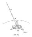
- FIGS. 7A-7Sare cross-sectional views of a portion of a patient's spine and back, demonstrating a method for introducing apparatus for modifying spinal tissue to an area in the spine for performing the tissue modification according to one embodiment of the present invention
- FIGS. 8A-8Fare cross-sectional views of a portion of a patient's spine and back, demonstrating a method for introducing apparatus for modifying spinal tissue to an area in the spine for performing the tissue modification according to an alternative embodiment of the present invention
- FIGS. 9A-9Bare cross-sectional views of a portion of a patient's spine and back, demonstrating a method for introducing apparatus for modifying spinal tissue to an area in the spine for performing the tissue modification according to an alternative embodiment of the present invention
- FIG. 10Ais a perspective view of a distal portion of an introducer sheath according to one embodiment of the present invention.
- FIGS. 10B and 10Care perspective and cross-sectional views, respectively, of a tissue shield device according to one embodiment of the present invention.
- FIGS. 10D and 10Eare perspective and cross-sectional views, respectively, of a tissue shield device according to an alternative embodiment of the present invention.
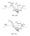
- FIGS. 11A and 11Bare cross-sectional views of a spine with a tissue modification device in position for modifying tissue according to various embodiments of the present invention.
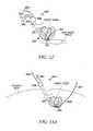
- FIG. 12is a cross-sectional view of a portion of a spine with a tissue modification device in position for modifying tissue according to an alternative embodiment of the present invention.
- FIGS. 13A-13Eare cross-sectional views of a portion of a spine with a tissue modification device in position for modifying tissue according to various alternative embodiments of the present invention.
- FIGS. 13F and 13Gare cross-sectional views of a portion of the tissue modification device of FIG. 13E , through line C-C on FIG. 13E , in various configurations according to one embodiment of the present invention.
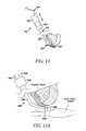
- FIG. 14is a cross-sectional view of a portion of a spine with a tissue modification device having a steerable distal portion in position for modifying tissue according to one embodiment of the present invention.
- FIG. 15Ais a cross-sectional view of a portion of a spine with a tissue modification device in position for modifying tissue according to one embodiment of the present invention.
- FIG. 15Bis a close-up of portion D-D of FIG. 15A .
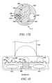
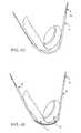
- FIG. 16is a cross-sectional view of a portion of a spine with a tissue modification device in position for modifying tissue according to one embodiment of the present invention.
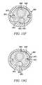
- FIGS. 17A-17Eare cross-sectional views taken through line A-A of FIG. 16 according to various alternative embodiments of the present invention.
- FIG. 18is a cross-sectional view taken through line B-B of FIG. 16 according to one embodiment of the present invention.
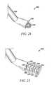
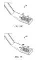
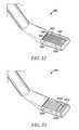
- FIGS. 19-33are perspective or side views of a distal portion of a tissue modification device according to various alternative embodiments of the present invention.
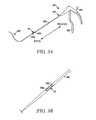
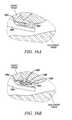
- FIGS. 34A and 34Bare perspective views of a distal portion of a tissue modification device according to alternative embodiments of the present invention.
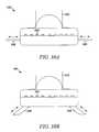
- FIGS. 35A and 35Bare side views of a distal portion of a tissue modification device according to one embodiment of the present invention.
- FIGS. 36A and 36Bare side views of a distal portion of a tissue modification device according to an alternative embodiment of the present invention.
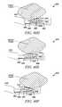
- FIGS. 37A and 37Bare perspective views of a distal portion of a tissue modification device according to an alternative embodiment of the present invention.
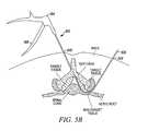
- FIGS. 38A-38Care end-on views of a distal portion of a tissue modification device according to various alternative embodiments of the present invention.
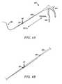
- FIGS. 39A-39Dare perspective ( FIG. 39A ), cross-sectional ( FIG. 39B ) and top ( FIGS. 39C and 39D ) views of a distal portion of a tissue modification device according to one embodiment of the present invention.
- FIGS. 40A-40Fare perspective ( FIG. 40A ), cross-sectional perspective ( FIG. 40B ), and cross-sectional side ( FIGS. 40C-40F ) views of a distal portion of a tissue modification device according to an alternative embodiment of the present invention.
- a tissue modification device 102may include an elongate body 108 having a proximal portion 107 and a distal portion 109 , a handle 104 with an actuator 106 coupled with proximal portion 107 , one or more tissue modifying members 110 , and one or more protective surfaces 112 .
- modification device 102may be introduced into an area for performing a treatment, such as a spine, using any of a number of different introduction methods, devices and systems 100 .
- modification device 102extends through an introducer device 114 placed through a first incision 240 on the patient's back and into the central spinal canal.
- Modification device 102is advanced along a guide member 116 , which extends through introducer member 114 , through the intervertebral foramen between two adjacent vertebrae (only part of one vertebra is shown in FIG. 2 ), and out a second (or “distal”) incision 242 on the back.
- guide memberhas a beveled distal tip 117 for facilitating advancement of guide member 116 through tissue.
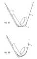
- FIGS. 41-46are partial cross-sectional views through a patient's spine, illustrating a double barrel system used with additional methods and apparatus for placement of an abrasion apparatus through the neural foramina for selective surgical removal of tissue.
- tissue modification device 102may be advanced to a position in the spine such that tissue modifying member 110 faces target tissue to be modified, such as buckled, thickened or otherwise impinging ligamentum flavum tissue as shown in FIG. 2 .
- Modification device 102is configured such that when tissue modifying member 110 faces the target tissue, protective surface(s) 112 face non-target tissue.
- Protective surface 112may be simply a length of elongate body 108 or may have one or more protective features, such as a widened diameter, protective or lubricious coating, extendable barrier, drug-eluting coating or ports, or the like.
- protective surface(s) 112may act as “non-tissue-modifying” surfaces, in that they may not substantially modify the non-target tissue.
- protective surface(s) 112may affect non-target tissue by protecting it in some active way, such as by administering one or more protective drugs, applying one or more forms of energy, providing a physical barrier, or the like.
- an anchoring forcemay be applied at or near distal portion 109 of elongate body 108 , either inside or outside the patient's body.
- a tensioning forcemay also be applied at or near proximal portion 107 of elongate body 108 , such as by pulling on handle 104 (one-directional arrows), and actuator 106 may be used (two-headed arrow) to activate tissue modifying member(s) 110 to modify target tissue.
- anchoring forceis applied near distal portion 109 by a user's hand 244 , and handle 104 is pulled proximally (arrows) to apply tensioning force.
- hand 244may grasp guide member 116 at or near its distal portion 117 and thus apply anchoring force to it, thus also applying anchoring force to elongate body 108 .
- elongate body 108 or handle 104may optionally be adjustably clamped to guide member 116 to further enhance or facilitate application of anchoring force to elongate body 108 .
- Tissue modification via tissue modifying members 110may include cutting, ablating, dissecting, repairing, reducing blood flow in, shrinking, shaving, burring, biting, remodeling, biopsying, debriding, lysing, debulking, sanding, filing, planing, heating, cooling, vaporizing, delivering a drug to, and/or retracting the target tissue.
- tissue modification device 102 and any introducer devices 114 , guide members 116 or other devicesmay be removed from the patient.
- tissue modifying member(s) 110may be disposed along any suitable length of body 108 .
- tissue modifying members 110may be disposed along a length of the device measuring no longer than 10 cm, and preferably no more than 6 cm, and even more preferably no more than 3 cm.
- tissue modifying member(s) 110may include a rongeur, a curette, a scalpel, one or more cutting blades, a scissors, a forceps, a probe, a rasp, a file, an abrasive element, one or more small planes, an electrosurgical device, a bipolar electrode, a unipolar electrode, a thermal electrode, a rotary powered mechanical shaver, a reciprocating powered mechanical shaver, a powered mechanical burr, a laser, an ultrasound crystal, a cryogenic probe, a pressurized water jet, a drug dispensing element, a needle, a needle electrode, or some combination thereof.
- all tissue modifying members 110may be mobile relative to the elongate body, all may be static, or some may be mobile and some may be static.
- tissue modification device 102may include elongate body 108 having proximal portion 107 and distal portion 109 , a window 111 disposed along elongate body 108 , two tissue modifying blades 110 exposed through window 111 , and handle 104 with actuator 106 coupled with proximal portion 107 .
- the tissue modifying memberscomprise blades 110 , although in alternative embodiments other tissue modifying members may be added or substituted.
- elongate body 108may have any number of dimensions, shapes, profiles and amounts of flexibility.
- distal portion 109is shown having a curved shape to demonstrate that at least a portion of elongate body 108 may be flexible.
- elongate body 108may have one or more of a round, ovoid, ellipsoid, flat, cambered flat, rectangular, square, triangular, symmetric or asymmetric cross-sectional shape.
- elongate body 108has a relatively flat configuration, which may facilitate placement of body 108 between target and non-target tissues.
- Distal portion 109 of body 108may be tapered, to facilitate its passage into or through narrow spaces as well as through small incisions on a patient's skin.
- Body 108may also include a slightly widened portion around the area of window 111 and blades.
- body 108may have a small profile, such as having a height of not more than 10 mm at any point along its length and a width of not more than 20 mm at any point along its length, or more preferably a height not more than 5 mm at any point along its length and a width of not more than 10 mm at any point along its length, or even more preferably a height not more than 2 mm at any point along its length and a width of not more than 4 mm at any point along its length.
- Body 108may be long enough to extend through a first incision on a patient, between target and non-target tissue, and out a second incision on a patient.
- body 108may be long enough to extend through a first incision, between the target and non-target tissue, and to an anchoring location within the patient.
- body 108may be long enough to extend through a first incision, between the target and non-target tissue, to a location nearby but distal to the target tissue within the patient, with some portion of tissue modification device 102 anchored to guide member 116 .
- elongate body 108includes at least one feature for allowing passage of the body over a guidewire or other guide member or to allow passage of one or more guide members over or through body 108 .
- body 108may include one or more guidewire lumens, rails, tracks, lengthwise impressions or some combination thereof.
- elongate body 108is predominantly flexible along its length and comprises any suitable flexible material, such as thin, flexible metals, plastics, fabrics or the like.
- it may be advantageous to include one or more rigid sections in elongate body 108such as to impart pushability to a portion of body 108 or to facilitate application of force to tissue modification members 110 without causing unwanted bending or kinking of elongate body 108 .
- rigiditymay be conferred by using additional materials in body 108 or by making the rigid portions thicker or wider or of a different shape.
- Handle 104may have any suitable configuration according to various embodiments.
- actuator 106may include any of a number of actuation devices in various embodiments.
- actuator 106comprises a trigger or moving handle portion, which is grasped by a user and pulled or squeezed toward handle 104 to bring blades 110 together to cut tissue.
- actuator 106instead may include a switch or button for activating a radiofrequency surgical ablation tissue modifying member.
- actuator 106may include a combination trigger and switch, one or more pull wires, any suitable form of lever and/or some combination thereof.
- the distal portion of body 108may have a very low profile (height compared to width), as shown in side view FIG. 3D , where only blades 110 protrude from the top surface of the elongate body 108 .
- a guidewire tube 120(or lumen) may extend from (or be coupled with) a lower surface of elongate body 108 .
- the lower surface of elongate body 108is an example of a protective or non-tissue-modifying surface.
- distal blade 110 ais coupled with two pull-wires 118 , as seen in FIGS. 3C , 3 E and 3 F.
- Pull-wires 118coupled to and translated by actuator 106 on handle 104 may be used to drive distal blade 110 a proximally to contact the cutting edge of proximal blade 110 b , thus cutting tissue.
- Other alternative mechanisms for driving blades 110such as gears, ribbons or belts, magnets, electrically powered, shape memory alloy, electro magnetic solenoids and/or the like, coupled to suitable actuators, may be used in alternative embodiments.
- distal blade 110 a and/or proximal blade 110 bmay have an outwardly curvilinear shape along its cutting edge.
- distal blade 110 amay have a different blade shape, including flat, rectilinear, v-shaped, and inwardly curvilinear (concave vs. convex).
- the cutting edge of either blade 110may have a sharp edge formed by a simple bevel or chamfer.
- a cutting edgemay have tooth-like elements that interlock with a cutting edge of an opposing blade, or may have corrugated ridges, serrations, rasp-like features, or the like.
- both blades 110may be of equal sharpness, or alternatively one blade 110 may be sharp and the other substantially flat to provide a surface against which the sharp blade 110 may cut.
- both cutting edgesmay be equally hard, or a first cutting edge may be harder than a second, the latter of which deflects under force from the first harder edge to facilitate shearing of the target tissue.
- FIGS. 3E and 3Fshow cross-sectional views through elongate body at lines A-A and B-B, respectively, of FIG. 3C .
- all or a portion of elongate body 108may include a lubricious surface for facilitating manipulation of the tool in the surgical space and at the anatomical site.
- the lubricious lower surfacealso provides a barrier between blades 110 and non-target tissue in the surgical space.
- the lower surfacemay include a guide member lumen 120 to accommodate a guidewire or other access device or rail.
- FIG. 3Eshows distal blade 110 coupled with pull wires 118 .
- proximal blade 110 bwhich is not coupled with pull wires 118 but rather fixed to body 108 .
- proximal blade 110 bmay be movable distally while distal blade 110 a is static, both blades may be moved toward one another, or a different number of blades may be used, such as one blade drawn toward a backstop or more than two blades, one or more of which may be mobile.
- guide member lumen 120may be accommodated on a side surface or more centrally within elongate body 108 .
- the one or more guide member lumens 120may comprise one or more various cross sectional shapes, for example substantially round, substantially oval, or substantially rectabular, to accommodate alternative guide members, for example flat or rectangular guidewires, needles or rails.
- guide member lumen 120may be adjustably coupled with the elongate body 108 to enable manipulation of the location of the elongate body 108 and therefore the tissue modifying members 110 relative to the guiding member.
- blades 110are shown in their closed position.
- distal blade 110 awhen distal blade 110 a is drawn proximally to cut tissue, at least some of the cut tissue is captured in a hollow interior portion of elongate body 108 .
- Various embodimentsmay further include a cover, a cut tissue housing portion and/or the like for collecting cut tissue and/or other tissue debris. Such collected tissue and debris may then be removed from the patient during or after a tissue modification procedure.
- distal blade 110 amay be drawn proximally to cut tissue, allowed to retract distally, and drawn proximally again to further cut tissue as many times as desired to achieve a desired amount of tissue cutting.
- Blades 110may be made from any suitable metal, polymer, ceramic, or combination thereof.
- Suitable metalsmay include but are not limited to stainless steel, nickel-titanium alloy, tungsten carbide alloy, or cobalt-chromium alloy, for example, ElgiloyTM (Elgin Specialty Metals, Elgin, Ill., USA), ConichromeTM (Carpenter Technology, Reading, Pa., USA), or PhynoxTM (Imphy SA, Paris, France).
- materials for the blades or for portions or coatings of the bladesmay be chosen for their electrically conductive or thermally resistive properties.
- Suitable polymersinclude but are not limited to nylon, polyester, DacronTM, polyethylene, acetal, DelrinTM (DuPont, Wilmington, Del.), polycarbonate, nylon, polyetheretherketone (PEEK), and polyetherketoneketone (PEKK).
- polymersmay be glass-filled to add strength and stiffness. Ceramics may include but are not limited to aluminas, zirconias, and carbides.
- blades 110may be manufactured using metal injection molding (MIM), CNC machining, injection molding, grinding and/or the like.
- Pull wires 118be made from metal or polymer and may have circular, oval, rectangular, square or braided cross-sections. In some embodiments, a diameter of a pull wire 118 may range from about 0.001′′-0.050′′, and more preferably from about 0.010′′-0.020′′.
- activating blades 110may cause them to modify target tissue along an area having any of a number of suitable lengths.
- blades 110may operate along a length of target tissue of no more than 10 cm, and preferably no more than 6 cm, and even more preferably no more than 3 cm.
- tissue modifying membersmay have many different lengths of activity.
- tissue modifying members and/or the elongate body and/or one or more additional features intended for just such a purposemay be composed of a material readily identifiable via x-ray, fluoroscopic, magnetic resonance or ultrasound imaging techniques.
- a number of different techniquesmay be used to prevent blades 110 (or other tissue modifying members) from extending significantly beyond the target tissue.
- preventing blades 110 from extending significantly beyond the target tissueinvolves holding tissue modification device 102 as a whole predominantly stable to prevent device 102 from translating in a direction toward its proximal portion or toward its distal portion while activating blades 110 .
- Holding device 102 stableis achieved by anchoring one end of the device and applying tensioning force at or near the other end, as described further below.
- pull wires 118are retracted proximally by squeezing actuator 106 proximally.
- squeezing actuator 106may cause both blades 110 to translate inward so that they meet approximately in the middle of window 111 .
- distal blade 110 amay be returned to it's starting position by a pulling force generated from the distal end of device 102 , for example by using a distal actuator that is attached to distal wires, or by pulling on the distal guide member which is attached to distal blade 110 a .
- proximal blade 110 bmay be moved to cut by a pulling force generated from the distal end of device 102 , for example by using a distal actuator that is attached to distal wires, or by pulling on the distal guide member which is attached to proximal blade 110 b .
- squeezing actuator 106may cause proximal blade 110 b to move distally while distal blade 110 a stays fixed.
- one or more blades 110may move side-to-side, one or more blades 110 may pop, slide or bow up out of window 111 when activated, or one or more blades 110 may expand through window.
- one or more blades 110 and/or other tissue modifying members of device 102may be powered devices configured to cut, shave, grind, abrade and/or resect target tissue.
- one or more bladesmay be coupled with an energy transmission device, such as a radiofrequency (RF) or thermal resistive device, to provide energy to blade(s) 110 for cutting, ablating, shrinking, dissecting, coagulating or heating and thus enhancing tissue modification.
- RFradiofrequency
- a rasp or filemay be used in conjunction with or coupled with one or more blades.
- use of actuator 106 and one or more moving blades 110provides for tissue modification with relatively little overall translation or other movement of tissue modification device 102 .
- target tissuemay be modified without extending blades 110 or other tissue modification members significantly beyond an area of target tissue to be treated.
- a tissue modification device 202may include an elongate body 208 having a proximal portion and a distal portion 209 , a handle 204 and actuator 206 coupled with proximal portion, and a window 211 and tissue modifying member 210 disposed near distal portion 209 .
- tissue modifying member 210comprises an RF electrode wire loop.
- Wire loop 210may comprise any suitable RF electrode, such as those commonly used and known in the electrosurgical arts, and may be powered by an internal or external RF generator, such as the RF generators provided by Gyrus Medical, Inc. (Maple Grove, Minn.).
- Radio frequencymay be any of a number of different ranges of radio frequency, according to various embodiments.
- some embodimentsmay use RF energy in a range of between about 70 hertz and about 5 megahertz.
- the power range for RF energymay be between about 0.5 Watts and about 200 Watts.
- RF currentmay be delivered directly into conductive tissue or may be delivered to a conductive medium, such as saline or Lactate Ringers solution, which may in some embodiments be heated or vaporized or converted to plasma that in turn modifies target tissue.
- Distal portion 209includes a tapered tip, similar to that described above, to facilitate passage of elongate body 208 into narrow anatomical sites.
- Handle 204 and actuator 206are similar to those described above, although in the embodiment of FIGS. 4A-4C , actuator 206 may be used to change the diameter of the wire loop 210 .
- wire loop 210may be caused to extend out of window 211 , expand, retract, translate and/or the like.
- Some embodimentsmay optionally include a second actuator (not shown), such as a foot switch for activating an RF generator to delivery RF current to an electrode.
- Elongate body 208may be fabricated from any suitable material and have any of a number of configurations.
- body 208comprises a metal tube with a full-thickness slit (to unfold the tube into a flat form—not shown) or stiffening element (not shown).
- the split tubeprovides for a simple manufacturing process as well as a conductive pathway for bi-polar RF operation.
- the tubemay include a waist region 220 .
- insulators 222may be disposed around a portion of wire loop 210 so that only a desired portion of wire loop 210 may transfer RF current into the tissue for tissue modifying capability.
- Wire loop 210covered with insulators 222 may extend proximally into support tubes 218 .
- an electrode tissue modifying member(of which wire loop 210 is but one example) may be bipolar or monopolar.
- a sleeve 224 housed toward the distal portion of window 211may act as a return electrode for wire loop 210 in a bipolar device.
- Wire loop electrodes 210may be made from various conductive metals such as stainless steel alloys, nickel titanium alloys, titanium alloys, tungsten alloys and the like.
- Insulators 222may be made from a thermally and electrically stable polymer, such as polyimide, polyetheretherketone (PEEK), polytetrafluoroethylene (PTFE), polyamide-imide, or the like, and may optionally be fiber reinforced or contain a braid for additional stiffness and strength. In alternative embodiments, insulators 222 may be composed of a ceramic-based material.
- wire loop 210may be housed within elongate body 208 during delivery of tissue modification device 202 into a patient, and then caused to extend up out of window 211 , relative to the rest of body 208 , to remove tissue.
- Wire loop 210may also be flexible so that it may pop or bow up out of window 211 and may deflect when it encounters hard tissue surfaces.
- Wire loop 210may have any of a number of shapes, such as curved, flat, spiral or ridged.
- Wire loop 210may have a diameter similar to the width of body 208 , while in alternative embodiments it may expand when extended out of window 211 to have a smaller or larger diameter than that of body 208 .
- Pull wiresmay be retracted proximally, in a manner similar to that described above, in order to collapse wire loop 210 , decrease the diameter and lower the profile of the wire loop 210 , and/or pull wire loop 210 proximally to remove tissue or be housed within body 208 .
- the low profile of the collapsed wire loop 210facilitates insertion and removal of tissue modification device 202 prior to and after tissue modification.
- support tubes 218deflect toward the center of elongate body 208 .
- tissue modification device 202may include multiple RF wire loops 210 or other RF members.
- device 202may include one or more blades as well as RF wire loop 210 .
- wire loop 210may be used to remove or otherwise modify soft tissues, such as ligamentum flavum, or to provide hemostasis, and blades may be used to modify hard tissues, such as bone.
- two separate tissue modification devicesmay be used in one procedure to modify different types of tissue, enhance modification of one type of tissue or the like.
- tissue modification devices 202may include tissue modifying members such as a rongeur, a curette, a scalpel, a scissors, a forceps, a probe, a rasp, a file, an abrasive element, one or more small planes, a rotary powered mechanical shaver, a reciprocating powered mechanical shaver, a powered mechanical burr, a laser, an ultrasound crystal a cryogenic probe, a pressurized water jet, a drug dispensing element, a needle, a needle electrode, or some combination thereof.
- tissue modifying memberssuch as a rongeur, a curette, a scalpel, a scissors, a forceps, a probe, a rasp, a file, an abrasive element, one or more small planes, a rotary powered mechanical shaver, a reciprocating powered mechanical shaver, a powered mechanical burr, a laser, an ultrasound crystal a cryogenic probe, a pressurized water jet,
- tissue modifying membersthat stabilize target tissue, such as by grasping the tissue or using tissue restraints such as barbs, hooks, compressive members or the like.
- soft tissuemay be stabilized by applying a contained, low-temperature substance (for example, in the cryo-range of temperatures) that hardens the tissue, thus facilitating resection of the tissue by a blade, rasp or other device.
- one or more stiffening substances or membersmay be applied to tissue, such as bioabsorbable rods.
- FIGS. 5A-5Done embodiment of a method for modifying tissue in a spine is demonstrated in simplified, diagrammatic, cross-sectional views of a portion of a patient's back and spine.
- FIG. 5Ashows a portion of the patient's back in cross section, with a portion of a vertebra, the spinal cord with branching nerve roots, and target tissue, which in this illustration is the ligamentum flavum and possibly a portion of the facet capsule.
- the target tissueis typically impinging directly on one or more of the group including nerve roots, neurovascular structures, dorsal root ganglia, cauda equina, or individual nerves.
- tissue modification device 102has been positioned in the patient's back to perform a tissue modification procedure.
- device 102may be positioned via a percutaneous or open surgical procedure, according to various embodiments.
- device 102may be inserted into the patient through a first incision 240 , advanced into the spine and between target tissue and non-target tissue (such as spinal cord, nerve roots, nerves and/or neurovascular tissue), and further advanced so a distal portion of elongate body 108 exits a second (or distal) incision 242 to reside outside the patient.
- target tissue and non-target tissuesuch as spinal cord, nerve roots, nerves and/or neurovascular tissue
- tissue modifying membersare positioned to face the target tissue, while one or more protective portions of elongate body 108 face non-target tissue.
- anchoring forcemay be applied at or near the distal portion of elongate body 108 .
- applying anchoring forceinvolves a user 244 grasping body 108 at or near its distal portion.
- anchoring forcemay be applied by deploying one or more anchor members disposed at or near the distal portion of body 108 , or by grasping a guidewire or other guide member extending through at least part of body 108 .
- proximally-directed tensioning forcemay be applied to device 102 , such as by pulling proximally on handle 104 (one-directional, diagonal arrows).
- This tensioning forcewhen applied to the substantially anchored device 102 , may help urge the tissue modifying member(s) against the target tissue (one-directional, vertical arrows near target tissue), thus enhancing contact with the target tissue and facilitating its modification.
- actuator 106With the tissue modifying member(s) contacting the target tissue, actuator 106 may be squeezed or pulled (two-headed arrow) to cause the tissue modifying member(s) to modify tissue. (Alternative actuators may be activated in different ways in alternative embodiments.)
- the distal portion of elongate body 108may be anchored within or outside the patient before the tissue modifying members are positioned adjacent the target tissue.
- the proximal portion of device 102may be anchored, and the tensioning force may be applied to the distal portion of device 102 .
- tensioning forcemay be applied to both ends of the device.
- a second handle and actuatormay be coupled with the distal end of body 108 after it exits the patient's back, allowing tensioning forces as well as tissue modifying actuation to occur at both the proximal and distal portions of device 102 .
- tissue modifying membersBy anchoring one end of device 102 and applying tensioning force to the opposite end, contact of the tissue modifying members with the target tissue is enhanced, thus reducing or eliminating the need for translating or otherwise moving device 102 as a whole and reducing the overall profile and the resulting access pathway required to position the device. Reducing movement and profile of device 102 and using tissue modifying members confined to a relatively small area of device 102 helps facilitate target tissue modification while minimizing or eliminating damage to surrounding tissues or structures.
- tissuemay be modified using one tissue modification device or multiple devices, according to various embodiments.
- an RF electrosurgical tissue modification devicemay be used in the patient to remove soft tissue such as ligament, and a bladed tissue modification device such as a rongeur may then be used to remove additional soft tissue, calcified soft tissue, or hard tissue such as bone.
- tissue modification devicesuch as a rongeur may then be used to remove additional soft tissue, calcified soft tissue, or hard tissue such as bone.
- multiple devicesmay be inserted, used and removed serially, while in alternative embodiments such devices may be inserted into the patient at the same time to be used in combination.
- FIG. 5Dusing one or more tissue modification devices 102 , a desired amount of target tissue may be removed from more than one area in the spine.
- FIGS. 5A-5Cdemonstrate removal of target tissue on one side of the spine, and that method or a similar method may also be used to remove target tissue on an opposite side of the spine, as shown in FIG. 5D , where target tissue has been removed from both sides.
- That the desired amount of tissue has been removedmay be confirmed by tactile feedback from the device or from a separate device, by testing nerve conduction through one or more previously impinged nerves, by testing blood flow through one or more previously impinged blood vessels, by passing (independently or over the guide member) a measurement probe or sound through the treated portion, through one or more radiographic tests, through some combination thereof, or by any other reasonable means.
- anchoring membersmay include but are not limited to one or more handles, barbs, hooks, screws, toggle bolts, needles, inflatable balloons, meshes, stents, wires, lassos, backstops or the like.
- anchoring members 250may be disposed at the extreme distal portion 109 of elongate body 108 , while in other embodiments anchoring members 250 may be located more proximally. In the embodiment shown, anchoring members 250 are deployed at the patient's skin.
- anchoringmay be achieved outside the patient by deploying one or more anchoring members 250 above the skin and having a user grasp the anchoring members 250 .
- anchoringmay be achieved outside the patient by deploying one or more anchoring members 250 above the skin and having a user grasp anchoring members 250 , after tissue modification device 102 has been anchored to the guide member.
- anchoringmay be achieved outside the patient by attaching anchoring member 250 to an external device, for example one that is mounted on the patient or on the procedure table.
- anchoringmay be achieved outside the patient by attaching the guide member to an external device, for example one that is mounted to on the patient or on the procedure table, after tissue modification device 102 has been anchored to the guide member.
- Anchoring members 250generally are deployable from a first, contracted configuration to facilitate delivery of device 102 , to a second, expanded configuration to facilitate anchoring. This change in configuration may be achieved, for example, by using shape memory or super-elastic materials, by spring loading anchoring members 250 into body 108 or the like. In most embodiments, anchoring members 250 may also be collapsed down into the first, contracted configuration after a tissue modification procedure has been performed, to facilitate withdrawal of device 102 from the patient. In an alternative embodiment, anchoring members 250 may detach from body 108 and may be easily removable from the patient's skin.
- FIG. 6Bshows tissue modification device 102 with an alternative embodiment of a distal anchoring member 260 .
- distal anchoring member 260includes multiple hooks or barbs extended out the distal portion 109 of elongate body 108 within the patient's back. In using such an embodiment, it may not be necessary to pass guide member 117 through a second, distal incision on the patient, although in some embodiments guide member 117 may extend significantly beyond distal portion 109 .
- Anchoring member(s) 260may be deployed so as to anchor to bone, ligament, tendon, capsule, cartilage, muscle, or any other suitable tissue of the patient.
- anchoring members 260are retracted within elongate body for removal of device 102 from the patient.
- FIGS. 7A-7Sa system and method for introducing a tissue modification device into a spine is demonstrated.
- This system and methodmay be referred to as an “access system” or “access method,” in that they provide or facilitate gaining access to a target tissue to be modified.
- the embodiment shownis merely one exemplary embodiment, and any of a number of other suitable methods, devices or systems may be used to introduce one or more devices for modifying tissue in spine.
- a spinal tissue modification proceduremay be carried out through an open surgical approach. Therefore, the following description is provided primarily for exemplary purposes and should not be interpreted to limit the scope of the invention as it is defined in the claims.
- a device delivery methodfirst involves advancing an introducer cannula 300 coupled with a stylet 302 into the patient's back. Cannula 300 and stylet 302 are then passed between adjacent vertebrae and into the ligamentum flavum or an adjacent spinal ligament, as shown further in FIG. 7B . As shown in FIG. 7C , when the distal tip of cannula is positioned as desired, stylet 302 is removed. Referring to FIGS. 7D and 7E , a loss of resistance syringe 304 including a plunger 310 , barrel 308 and fluid and/or air 306 , is coupled with the proximal portion of cannula 300 .
- cannula 300is advanced through the ligamentum flavum until it enters the central spinal canal where a loss of resistance to pressure placed on plunger 310 is encountered, and fluid and/or air 306 is injected into central spinal canal to confirm correct placement of cannula 300 as shown in FIG. 7E .
- Syringe 304is then removed, as in FIG. 7F , and a guidewire 312 with a non-rigid, atraumatic tip is advanced through cannula 300 into the central spinal canal, as in FIG. 7G .
- cannula 300is removed, as in FIG. 7H , leaving behind guidewire 312 .
- an introducer sheath 114coupled with a dilator 314 , is then advanced over guidewire 312 to position a distal portion of sheath 114 at a desired location within the spine. Dilator 314 and guidewire 312 are then removed, as in FIG. 7K .
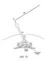
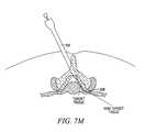
- one or more curved or steerable guide devices 318may be advanced through it to desired positions in and/or through the spine, as shown in FIGS. 7L and 7M .
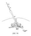
- One or more guide members 116may then be advanced through the guide device 318 , as shown in FIGS. 7N-7P .
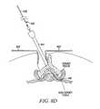
- guide device 318may be removed, as in FIG. 7Q , and elongate body 108 of tissue modification device 102 may be advanced over guide member 116 and through introducer sheath 114 to a desired position in the spine, as in FIG. 7R .
- FIG. 7QAs shown in FIG.
- elongate body 108may be tensioned to urge tissue modifying members 110 against target tissue, as shown with arrows at opposite ends of device 102 , while distal portion 109 is anchored, in this case by hand 244 .
- guide member 116may be tensioned to urge tissue modifying members 110 against target tissue as shown in FIG. 7R .
- the system and method described immediately abovemay include additional features or steps, may have fewer features or steps, may have an alternate order of implementation of steps, or may have different features or steps.
- placement of device 102will be performed in a medial-to-lateral direction (relative to the patient), while in alternative embodiments device placement will be performed lateral-to-medial.
- one or more components of the system describedmay be anchored to the patient, such as guide member 116 or introducer sheath 114 .
- one or more guide members 116may include one or more wires, rails or tracks and may be inserted through guide device 318 , introducer sheath 114 without guide device 318 , cannula 300 , an epidural needle, a lumen of an endoscope, a lumen of a tissue shield or barrier device, a curved guide device 318 placed through a lumen of an endoscope, or the like.
- guide device 318may be placed through introducer cannula 300 and then introducer sheath 114 may be passed over guide device 318 .
- Tissue modification device 102may similarly be inserted with or without using any of these devices or components in various combinations.
- Various guidewires 312 , guide devices 318 and/or guide members 116may be pre-shaped to have one or more curves, may be steerable, and/or may include one or more rails, tracks, grooves, lumens, slots, partial lumens, or some combination thereof.
- tissue modification device 102may be slidably coupled with one or more delivery devices during delivery and/or during use.
- tissue modification device 102is advanced through introducer sheath 114 and sheath 114 is used as an irrigation and evacuation lumen to irrigate the area of the target tissue and evacuate removed tissue and other debris, typically by applying a vacuum.
- tissue modification device 102may include an irrigation and/or evacuation lumen to irrigate an area of the target tissue and evacuate removed tissue and other debris.
- an access system for facilitating tissue modificationmay further include one or more visualization devices (not shown). Such devices may be used to facilitate placement of the access system for introducing the tissue modification device, to facilitate tissue modification itself, or any combination of these functions.
- visualization devicesinclude flexible, partially flexible, or rigid fiber optic scopes, rigid rod and lens endoscopes, CCD or CMOS chips at the distal portion of rigid or flexible probes, LED illumination, fibers or transmission of an external light source for illumination or the like.
- Such devicesmay be slidably couplable with one or more components of an access system or may be slidably or fixedly coupled with a tissue modification device.
- additional or alternative devices for helping position, use or assess the effect of a tissue modification devicemay be included.
- Examples of other such devicesmay include one or more neural stimulation electrodes with EMG or SSEP monitoring, ultrasound imaging transducers external or internal to the patient, a computed tomography (CT) scanner, a magnetic resonance imaging (MRI) scanner, a reflectance spectrophotometry device, and a tissue impedance monitor disposed across a bipolar electrode tissue modification member or disposed elsewhere on a tissue modification device or disposed on the access system.
- CTcomputed tomography
- MRImagnetic resonance imaging
- spectrophotometry devicea tissue impedance monitor disposed across a bipolar electrode tissue modification member or disposed elsewhere on a tissue modification device or disposed on the access system.
- a tissue modification device and optionally one or more introduction/access devicesmay be positioned in a patient using an open surgical technique.
- an open surgical incisionis made on a patient's back, and two retractors 402 are used to expose a portion of the patient's vertebra.
- an introducer sheath 414may then be inserted through the incision, between retractors 402 .
- a curved guide device 418may then be inserted through introducer sheath 414 .
- Guide device 418extends into the epidural space and through the intervertebral foramen as shown in FIG. 8D .
- a curved and cannulated thin, blunt probemay be placed directly through the open incision into the epidural space of the spine, or alternatively may be placed through introducer sheath 414 .
- the probe tipmay be advanced to or through a neural foramen.
- Such a probemay be similar in shape, for example, to a Woodson elevator, Penfield 3, hockey stick probe, ball tipped probe, or the like.
- probes that may be manually bent to change their shapes, or probes with articulating tips, or probes with shape lock portions, and/or probes having grooves instead of cannulasmay be used.
- a curved, flexible cannulamay be inserted through the curved guide device, until it extends lateral to the neural foramen, after which a substantially straight, flexible guidewire with a sharp tip may then be inserted through curved cannula and advanced so that its distal portion with sharp tip extends outside the patient's back.
- FIGS. 9A and 9Banother alternative open surgical access method is shown.
- a curved guide device 446is shown in place through the epidural space and intervertebral foramen, and a guidewire 440 with a beveled distal tip 442 is about to be advanced through guide device 446 .
- guidewire 440is directed by guide device 446 back through the open incision through which the various access devices are introduced. In such an embodiment, then, only one incision is created and the proximal and distal portions of one or more devices extend out of the patient's back through the same incision.
- open surgical accessmay be through exposure down to a vertebral lamina, through ligamentum flavum without lamina removal, through ligamentum flavum with partial or complete lamina removal, through ligamentum flavum with or without lamina removal with partial or complete medial facet joint removal, through open exposure and out through skin laterally, through open exposure and back out through the open exposure, or through a lateral open exposure that accesses the neural foramen from the lateral side.
- One or more visualization devicesmay be used with open surgical access procedures as well as with percutaneous or other less invasive procedures.
- a tissue modification devicemay be placed in the patient directly, without any introduction devices.
- the tissue modification devices 102 , 202include at least one non-tissue-modifying (or “protective”) portion, side or surface.
- the non-tissue-modifying portionis located on tissue modification device 102 , 202 so as to be positioned adjacent non-target tissue when tissue modifying members 110 , 210 are facing the target tissue.
- the non-tissue-modification surface of the deviceis configured so as to not modify or damage tissue, and thus the non-target tissue is protected from unwanted modification or damage during a tissue modification procedure.
- a protective surface or portion of tissue modification device 102 , 202may actually modify non-target tissue in a protective manner, such as by delivering a protective drug, coating, fluid, energy or the like to the non-target tissue.
- tissue modification devices or systemsmay further include one or more tissue barriers (or “shields”) for further protecting non-target tissues.
- tissue barriersmay be slidably coupled with, fixedly coupled with, or separate from the tissue modification devices with which they are used.
- a barriermay be delivered between target and non-target tissues before delivering the tissue modification device, may be delivered along with the tissue modification device, or may be delivered after delivery of the tissue modification device but before the device is activated or otherwise used to modify target tissue.
- a barriermay be interposed between the non-target tissue and one or more tissue modification devices to prevent unwanted damage of the non-target tissue.
- FIG. 10Ashows a distal portion of an introducer device 514 through which a barrier may be introduced.
- FIGS. 10B and 10Cshow one embodiment of a barrier 500 partially deployed and in cross-section, respectively.
- barrier 500will have a first, small-profile configuration for delivery to an area near non-target tissue and a second, expanded configuration for protecting the non target tissue.
- barrier 500may be configured as one piece of super-elastic or shape-memory material, as a scaffold with material draped between the scaffolding, as a series of expandable wires or tubes, as a semicircular stent-like device, as one or more expandable balloons or bladders, as a fan or spring-loaded device, or as any of a number of different devices configured to expand upon release from delivery device 514 to protect tissue.
- barrier 500may comprise a sheet of material disposed with a first end 502 a abutting a second end 502 b within introducer device 514 and unfurling upon delivery.
- FIGS. 10B and 10Cbarrier 500 may comprise a sheet of material disposed with a first end 502 a abutting a second end 502 b within introducer device 514 and unfurling upon delivery.
- barrier 500 , 520may be introduced via introducer device 514 in one embodiment or, alternatively, may be introduced via any of the various means for introducing the tissue modification device, such as those described in conjunction with FIGS. 7A-7S , 8 A- 8 F and 9 A- 9 B. In some embodiments, barrier 500 , 520 may be fixedly coupled with or an extension of a tissue modification device.
- Barrier 500 , 520may also include one or more lumens, rails, passages or the like for passing a guidewire or other guide member, for introducing, removing or exchanging any of a variety of tissue modification, drug delivery, or diagnostic devices, for passing a visualization device, for providing irrigation fluid at the tissue modification site, and or the like.
- barrier 500 , 520is advanced over multiple guidewires and the guidewires remain in place during a tissue modification procedure to enhance the stability and/or maintain positioning of barrier 500 , 520 .
- a powered tissue modification device 1000suitably includes an elongate shaft 1001 having a proximal portion 1002 , a distal portion 1003 and a longitudinal axis 1008 , one or more tissue modifying members 1004 coupled with shaft 1001 at or near distal portion 1003 , and a handle 1006 coupled with shaft 1001 at or near proximal portion 1002 .
- some embodimentsmay also include one or more power connectors 1010 for connecting device 1000 with one or more power sources.
- shaft 1001has a size and shape that facilitate passage of at least distal portion 1003 into an epidural space of the spine and between target tissue, such as ligamentum flavum, and non-target tissue, such as neural and/or neurovascular tissue.
- target tissuesuch as ligamentum flavum
- non-target tissuesuch as neural and/or neurovascular tissue.
- shaft 1001may include one or more bends or curves at or near its distal portion 1003 to further facilitate passage and positioning of device 1000 .
- a bend or curvemay facilitate passage of at least part of distal portion 1003 at least partway into an intervertebral foramen.
- the portion of device 1000 facing the non-target tissuemay be configured to modify the non-target tissue in some way, such as to protect the tissue with a delivered substance, and/or to test the non-target tissue to confirm that it is non-target tissue.
- handle 1006may have any suitable configuration and features.
- handle 1006includes one or more actuators for activating tissue modifying member(s) 1004 .
- Power connector 1010may have any suitable configuration and may deliver any suitable type of energy from an external power source (not shown) to device 1000 in various embodiments, such as but not limited to electric, radiofrequency, ultrasound, laser or conductive energy.
- device 1000may be battery operated or use any other suitable source of internal power or energy, and such internal energy source may be housed in handle 1006 , for example. From whatever source, power is typically transmitted to tissue modifying member(s) 1004 to activate them and thus modify tissue.
- tissue modification device 1000may be advanced into a patient using any of a number of suitable techniques and approaches, some of which have been described previously.
- FIG. 11Aillustrates one approach to advancing distal portion 1003 of device 1000 to a position between target and non-target tissue from a contralateral approach, while FIG. 11B illustrates an ipsilateral approach.
- distal portion 1003may include two or more bends and/or may be at least partially flexible or steerable to facilitate a desired approach angle, according to various embodiments.
- a tissue modification device 1020includes an elongate shaft 1011 having a proximal portion 1012 and a distal portion 1013 , one or more tissue modification member(s) 1014 , a conductive electrode 1015 coupled with shaft 1011 , a handle 1016 , a power connector 1030 , and multiple additional connection members 1032 , 1033 .
- Electrode 1015may be configured to deliver a non-target frequency and non-target amplitude of electrical current to non-target tissue. The non-target frequency and non-target amplitude may stimulate a response from a neural tissue.
- a first connection member 1032may provide power to electrode 1015 , and if non-target-tissue is stimulated by current from the electrode, the observation of this stimulation, as measured by EMG, SSEP or watching for muscular activation, provides evidence that electrode 1015 is adjacent the non-target tissue.
- a target stimulating electric currentmay also be delivered through second connection member 1033 to tissue modifying member(s) 1014 (e.g., composed of electrically conductive material) and/or to a target stimulating electrode located adjacent and on the same side of device 1020 as tissue modifying member(s) 1014 .
- the type (e.g., neural, non-neural) of the tissue immediately adjacent tissue modifying member(s) 1014may be determined based on the tissue response or lack thereof.
- device 1020may be configured to allow for control of the target stimulating electric current and the non-target stimulating electric current.
- the target stimulating electric current and the non-target stimulating electric currentmay be sequentially delivered to distal portion 1013 of device 1020 to determine the location of neural tissue prior to activation of tissue modifying member(s) 1014 , for example, to help ensure that tissue modifying member(s) 1014 do not damage neural tissue.
- tissue modifying member(s) 1014may include one or more of a rongeur, a curette, a scalpel, one or more cutting blades, a scissors, a forceps, a probe, a rasp, a file, an abrasive element, one or more small planes, an electrosurgical device, a bipolar electrode, a unipolar electrode, a thermal electrode, a rotary powered mechanical shaver, a reciprocating powered mechanical shaver, a powered mechanical burr, a laser, an ultrasound crystal, a cryogenic probe, a pressurized water jet, or some combination thereof. Some embodiments include one tissue modifying member 1014 , while others include multiple tissue modifying members 1014 . As is described further below, tissue modifying member(s) 1014 may have any of a number of suitable sizes, shapes and configurations and may move or actuate in any suitable way.
- a tissue modification device 1040includes an elongate shaft 1041 , one or more tissue modifying member(s) 1044 , a handle 1046 and a power connector 1050 . Additionally, device 1040 may include a guidewire lumen (not shown) extending through all or part of shaft 1041 , which may allow passage of a guidewire 1048 having proximal 1049 and distal 1047 ends therethrough. In one embodiment, for example, guidewire 1048 may extend from a proximal end of shaft 1041 through a distal end of shaft 1041 and out the patient. In some embodiments, as described previously above, anchoring and/or tensioning force may be applied at or near distal end 1047 and/or proximal end 1049 to help urge tissue modifying member(s) 1044 against target tissue.
- tissue modifying member 1044is shown having relatively flat configuration.
- tissue modification devicemay include a curved and/or flexible tissue modifying member 1045 (or multiple curved and/or flexible members), having a curved/flexible surface for contacting target tissue.
- Device 1040may also include a curved and/or flexible shaft 1042 .
- Such curved and/or flexible tissue modifying members 1045 (or tissue modifying surfaces) and shafts 1042may facilitate tissue modification in some embodiments, in that tissue modifying members 1045 may more readily conform to target tissue.
- many if not all of the devices described in the present applicationmay have such curved and/or flexible tissue modifying member(s).
- FIG. 13Cshows tissue modification device 1040 including a wire anchor 1060 coupled with guidewire 1048 .
- wire anchor 1060may be either removably or permanently attached to guidewire 1048 at or near its distal end 1047 to provide anchoring force against the patient's back from outside the patient.
- Wire anchor 1060may minimize or prevent guidewire 1048 from moving through the patient's back towards proximal end 1049 .
- additional anchoring and/or tensioning forcemay be applied to distal end 1047 , such as by holding and/or pulling distal end 1047 by hand.
- distal end 1047 of guidewire 1048may include one or more deployable anchoring members 1062 , which may be deployed within the patient to anchor into tissue of the patient's back, such as muscle, bone, ligament or the like.
- guidewire 1048may have one or more lumens (not shown), and anchoring members 1062 may be translated through the lumen(s) to extend out of distal end 1047 .
- anchoring members 1062may be retracted within the lumen(s) so that guidewire 1048 may be more easily removed from the patient.
- tissue removal device 1040may also include one or more proximal shaft anchoring members 1066 and/or one or more proximal guidewire anchoring members 1064 .
- Shaft anchoring member 1066may, in alternative embodiments, either be coupled with or removably couplable with shaft 1041 to facilitate application of anchoring force.
- shaft anchoring member 1066may abut the patient's back to resist translation of shaft 1041 into the patient.
- Proximal guidewire anchoring member 1064may be included in handle 1046 , as shown, or in other embodiments may be located proximal or distal to handle 1046 .
- Guidewire anchoring member 1064may be used to lock or anchor guidewire 1048 to prevent or minimize its translation into or out of device 1040 . This may help facilitate application of tensioning and/or anchoring force via guidewire 1048 .
- FIGS. 13F and 13Gshow cross-sectional views of handle 1046 and proximal guidewire anchoring member 1064 taken through line C-C on FIG. 13D .
- handle 1046may include proximal guidewire anchoring member 1064 , a tissue modifying drive 1068 in a first lumen, a guidewire 1048 in a guidewire lumen 1070 , multiple guiding slots 1074 with corresponding guiding tabs 1075 , and one or more lobes 1072 .
- FIG. 13Fwhen guidewire anchoring member 1064 is disengaged, guidewire 1048 may freely translate within guidewire lumen 1070 , because lobe 1072 does not interfere.
- FIG. 13Fwhen guidewire anchoring member 1064 is disengaged, guidewire 1048 may freely translate within guidewire lumen 1070 , because lobe 1072 does not interfere.
- FIG. 13Fwhen guidewire anchoring member 1064 is disengaged, guidewire 1048 may freely translate within guidewire lumen 1070 , because lobe 10
- guidewire 1048may friction fit (e.g., clamp, pinch) between lobe 1072 of guidewire anchoring member 1064 and the wall of guide wire lumen 1070 .
- Guidewire anchoring member 1064may then be translated and/or rotated back to the original position ( FIG. 13F ) to disengage guidewire 1048 .
- a tissue removal device 1100may include an elongate shaft 1104 having proximal 1106 and distal 1105 portions, one or more tissue modifying members 1108 , a movable handle 1103 coupled with proximal portion 1106 , and a power connector 1107 .
- distal portion 1105is at least partially steerable (shown in FIG. 14 as two, overlapping distal portions), and movable handle 1103 may be used (two-headed, straight arrow) to steer distal portion 1105 while holding shaft 1104 relatively stationary.
- a steerable distal portion 1105may enhance the ability of tissue modifying members 1108 to contact and apply force against target tissue.
- the location of tissue modifying members 1108may be adjusted, using steerable distal portion 1105 , without significantly moving shaft 1104 .
- steerable distal portion 1105may move in multiple directions, such as laterally and up-and-down, relative to the longitudinal axis of shaft 1104 .
- Movable handle 1103may operate with a piston-like motion, in one embodiment, where a distal portion of handle 1102 is attached to the shaft and a proximal portion handle 1103 is attached to a tensioning member. The tensioning member may translate tension to steerable distal end 1105 when handle 1103 is actuated, which in turn deflects distal end 1105 .
- any other handle steering mechanisms and/or other steering mechanismsmay be used.
- FIGS. 15A and 15Bshow one embodiment of a tissue modification device 1080 , which includes an elongate shaft 1081 , one or more tissue modifying members 1082 , a handle 1084 , a visualization device 1086 , an optical cable 1090 and a power connector 1088 .
- Visualization device 1086may include any suitable device, such as but not limited to an endoscope.
- An endoscope visualization devicemay have lenses and/or fiber optics, for example, for delivering light (or other energy) to illuminate the tissue and capturing images.
- visualization device 1086may include one or more image capturing elements 1094 and one or more illuminating elements 1092 .
- Image capturing element 1094may include, for example, a CCD or CMOS chip, in some embodiments.
- Illuminating element 1092may include, for example, one or more light emitting diodes (LEDs) or fiber optics, in some embodiments.
- LEDslight emitting diodes
- optical cable 1090may include fiber optics. Some or all of the fiber optics may comprise or may be coupled with illuminating elements 1092 . Alternatively or additionally, some or all of the fiber optics may be connected to a camera (not shown). For example, such a camera may be attached to the proximal end of tissue modification device 1080 .
- Optical cable 1090may alternatively include one or more electrical wires connected to a power source (e.g., to power LED(s)) and/or an image capturing element 1094 . Lenses, fiber optics, LED(s), or combinations thereof may be used for illumination with lenses, fiber optics, CCD, CMOS, or combinations thereof used for image capturing, according to various embodiments.
- tissue modification device 1120may suitably include an elongate shaft 1132 , one or more tissue modifying members 1130 , a handle 1124 , a visualization device 1122 , an optical cable 1128 and a power connector 1126 .
- visualization device 1122is located proximal to tissue modifying member(s) 1130 on shaft 1132 .
- visualization device(s) 1112may be positioned along shaft 1132 at any desired location.
- FIGS. 17A-17Eshow cross-sectional views of various embodiments of shaft 1132 , from the perspective of line A-A in FIG. 16 .
- shaft 1132may include a tissue modifying drive 1134 within a tissue modifying drive lumen 1140 , and a guidewire 1136 within a guidewire lumen 1138 .
- Tissue modifying drive 1134may be configured to translate or rotate with respect to tissue modifying drive lumen 1140 .
- tissue modifying drives 1134include, but are not limited to, a drive shaft, one or more conductive wires, one or more optical fibers, or the like.
- Various embodimentsmay also include a motor, which may be located in the handle of the device, near the device distal end, in a separate drive apparatus, or the like.
- shaft 1132may include tissue modifying drive 1134 within tissue modifying drive lumen 1140 , guidewire 1136 within guidewire lumen 1138 , conductive elements 1146 within a visualization lumen 1144 , and suction/irrigation lumen 1142 .
- Suction/irrigation lumen 1142may be used, for example, to deliver gas, fluid or pushable solids (e.g., granular solids) from outside the patient to the distal end of the device or to aspirate gas, fluids, tissue and/or other material from the targeted tissue region to the outside of the patient.
- Suction/irrigation lumen 1142may also be used, in some embodiments, to slidably pass instruments, such as a long flexible needle or biopsy forceps.
- Visualization lumen 1144may be configured to receive conductive elements 1146 , such as elements to power LEDs at the distal end of the device, and/or to carry the signal from a CCD or CMOS chip located at the distal end of the device that has captured a visual image and converted it into an electronic signal to a display device located outside the patient.
- shaft 1132may include tissue modifying drive 1134 within tissue modifying drive lumen 1140 , conductive elements and/or fiber optics 1152 within visualization lumen 1144 , and separate suction 1150 and irrigation 1148 lumens.
- Suction lumen 1150 and irrigation lumen 1148may be used, in some embodiments, to simultaneously or sequentially deliver and remove gases, fluids and/or pushable solids to and from the distal end of a tissue modification device. Delivery and removal of gases, fluids and/or pushable solids may help clear detached and/or non-detached target tissue and other debris from the treatment site and/or maintain a clear visualization of the target and non-target tissue via the visualization element.
- fiber optics 1152may be disposed within a hollow shaft 1132 , in between various lumens 1148 , 1150 , 1144 , 1140 .
- fiber optics 1152may be replaced with electrical conductors in other embodiments.
- Fiber optics 1152may deliver light to illuminate the target tissue and/or deliver light from the tissue to a viewing device.
- Visualization lumen 1144in such an embodiment, may transport light or electrical signals in proximal and/or distal directions.
- shaft 1132may include a steering actuator 1154 within a steering lumen 1156 .
- Steering actuator 1154may be used, for example, to help steer a distal portion of a tissue modification device, as described in further detail above.
- FIG. 18is an end-on cross-sectional view of tissue modification device 1120 of FIG. 16 , shown from the perspective of line B-B.
- visualization device 1122 and illuminating elements 1158are located proximal to tissue modifying member 1130 .
- tissue modifying member 1130includes a rotating disc mounted on a post in a bearing 1160 , with multiple raised cutting edges 1131 on the disc.
- Two suction/irrigation lumens 1142allow for introduction and suction of gas, fluid and/or pushable solids from an area of tissue modification.
- FIGS. 19-40Fillustrate a number of embodiments of a distal end of a tissue modification device having various different tissue modifying members.
- a tissue modification device 1170may include multiple tissue modifying members 1172 , each including a cup 1174 attached to a drive shaft 1173 and having a cutting edge 1175 .
- Tissue modifying membersare located within an open chamber 1176 formed by multiple walls 1178 , 1180 , 1182 , 1184 , 1186 .
- Cups 1174may be rotated and/or translated to cut target tissue disposed in open chamber 1176 , as shown by the curved and straight arrows.
- FIG. 19Aillustrates an alternative embodiment in which a tissue modification device 1170 a may include a shaft 1171 , which is curved and/or flexible along at least part of its length, and a tissue modifying portion 1177 , which is also curved and/or flexible.
- Tissue modifying portion 1177may include curved and/or flexible shafts 1173 a , and cups 1174 a , similar to those shown in FIG. 19 .
- many of the embodiments described hereinmay have either flat/straight tissue modifying members/surfaces or curved and/or flexible tissue modifying members/surfaces, according to various embodiments. Therefore, although many of the following embodiments of tissue modifying members are shown and described as having generally flat configurations, in alternative embodiments, many if not all such tissue modifying members may have curved and/or flexible configurations instead.
- a tissue modification device 1190may include multiple tissue modification members 1192 , each comprising a hollow tube 1194 with a cutting edge 1193 .
- tubes 1194may be rotated and translated to cut tissue. Tubes 1194 may also be used for suction and/or irrigation in some embodiments.
- FIG. 21shows another alternative embodiment, in which a tissue modification device 1200 includes a tissue modifying member 1202 comprising a disc and multiple raised cups 1204 , each cup having a cutting edge 1205 , and the disc being mounted on a drive shaft 1206 .
- tissue modifying membermay oscillate by moving shaft 1206 back and forth and/or may rotate by rotating the disc around an axis.
- a tissue modification device 1210may include two rotating tissue modification members 1212 a , 1212 b , each comprising a disc with raised cutting members.
- the discsmay rotate in the same directions or opposite directions in various embodiments.
- Rotating members 1212 a , 1212 b in opposite directionsmay help balance forces between the two members 1212 a , 1212 b and target tissue, thereby helping stabilize tissue modification device 1210 and enhance tissue modification procedures.
- FIG. 23illustrates that, in some embodiments, a tissue modifying member 1224 of a tissue modification device 1220 may be angled relative to a longitudinal axis of a distal portion 1126 of a shaft 1222 .
- Angling tissue modifying member 1224 away from the long axis of distal portion 1126may allow tissue modifying member 1224 to extend out of a an open chamber or window, for example, to facilitate tissue in various embodiments.
- Angling tissue modifying member 1224may also enhance contact of tissue modifying member 1224 with target tissue, thus enhancing tissue modification.
- a tissue modification device 1230may include a tissue modification member 1234 that extends out of a distal opening 1236 at the distal end of a shaft 1232 .
- tissue modification member 1234may be moved back and forth to be housed within or to extend out of distal opening 1236 .
- tissue modification member 1234may be fixed in relation to opening 1236 .
- FIG. 25shows another embodiment of a tissue modification device 1240 , which includes tissue modifying members 1242 , each including a rotating shaft 1244 , 1246 and a helical cutting blade 1248 .
- Device 1240also may include one or more irrigation ports 1250 and one or more suction ports 1252 .
- cutting blades 1248may be configured to remove both hard and/or soft tissue.
- Cutting blades 1248may also be configured to transport separated tissue proximally toward and/or into the shaft of device 1240 , and/or suction port 1252 , so that such tissue may be removed from the patient.
- Rotating shafts 1244may be configured to rotate in opposite directions, in some embodiments, thus helping balance forces exerted by tissue modifying members 1242 on target tissues.
- a tissue modification device 1260may include a tissue modifying member 1262 comprising a belt 1266 , mounted on rotating rollers 1264 and carrying multiple raised abrasive members 1268 . Rollers 1264 may be activated to rotate, thus causing belt 1266 to move, and thus causing abrasive members 1268 to abrade target tissue.
- a tissue removal device 1270may include a tissue modifying member 1272 comprising a belt 1276 , mounted on rotating rollers 1278 and carrying multiple raised cutting members 1274 . Rollers 1278 may be activated to rotate, thus causing belt 1276 to move, and thus causing cutting members 1274 to cut target tissue.
- a tissue removal device 1280may include a tissue modifying member 1286 comprising one or more wires that move along multiple transverse guide rails 1282 , 1284 .
- tissue modifying member 1286may move laterally along guide rails 1282 , 1284 and may also translate over guide rails 1282 , 1284 .
- the tissue modifying member(s) 1286i.e., the wire(s)
- the wire(s)may translate, rotate, reciprocate and/or oscillate.
- the wire(s)may be coated (e.g., on the outer surface) with an abrasive material, and/or have a high friction outer texture.
- the wiresmay be coupled to an energy (e.g., RF current, thermal) generator.
- wiresmay be solely at or within the shaft distal portion or may extend from the shaft distal end to a more proximal location along shaft.
- FIG. 29illustrates another embodiment of a tissue modification device 1290 , in which a tissue modifying member 1292 is coupled with rotating drive post 1294 and two free posts 1296 , 1298 .
- Drive post 1294is coupled with a drive shaft 1302 , which turns drive post 1294 , thus translating tissue modifying member 1292 to modify tissue.
- Tissue modifying member 1292may be elevated above a floor 1300 of the device shaft, so as to more easily contact target tissue.
- tissue modifying member 1292comprises a cutting wire or abrasive wire and may be translated either in one direction or in both directions.
- drive shaft 1302may be advanced and retracted to further move and/or change the configuration of tissue modifying member 1292 .
- a tissue modification device 1310may include a tissue modifying member 1312 comprising a movable platform with an abrasive surface and coupled with a drive shaft 1314 extending out of a distal opening 1316 .
- tissue modifying member 1312may move laterally ( FIG. 30A ), may translate back and forth ( FIG. 30B ) and/or may vibrate ( FIG. 30C ).
- a tissue modification device 1320may include a tissue modification member 1322 comprising an oval or round platform with an abrasive surface and coupled with a drive shaft 1324 extending out of a distal opening 1326 .
- tissue modifying member 1322may be made to rotate or move in a circular pattern, as well as translate, move laterally, oscillate and/or vibrate according to various embodiments.
- a tissue modification device 1330includes multiple tissue modifying members 1332 , each including a movable platform 1333 with an abrasive surface attached to a drive shaft 1334 .
- Tissue modifying membersmay move back and forth relative to one another and to the device shaft in any suitable pattern. Moving tissue modifying members 1332 back and forth relative to one another may help them apply tensioning forces to target tissue, thereby enhancing the ability of tissue modifying members 1332 to cut, shear, tear and/or otherwise modify target tissues.
- a tissue modification device 1340may suitably include tissue modifying members comprising one or more blades, such as a distal blade 1344 a and a proximal blade 1344 b , each having a cutting edge 1345 a , 1345 b .
- proximal blade 1344 bis movable and may translated distally toward the opposing distal blade 1344 a .
- distal blade 1344 amay be movable or both blades 1344 a , 1344 b may be movable.
- Alternative embodimentsmay include one movable blade, more than two movable blades facing in one direction, more that two movable blades facing in different directions, a movable blade and a backstop against which the blade may be driven, or any other suitable combination of movable and/or immobile blades.
- any blade of any given embodimentmay have any suitable shape, size and overall configuration. In some embodiments, blades may be flat, while in others they may be curved, squared off, ridged, bent, serrated or the like.
- Blades 1344 a , 1344 bmay be fabricated from metals, polymers, ceramics, any other suitable material or combination of materials.
- suitable metals for bladesmay include, but are not limited to, stainless steel, nickel-titanium alloy, or cobalt-chromium alloy, for example, ElgiloyTM (Elgin Specialty Metals, Elgin, Ill., USA), ConichromeTM (Carpenter Technology, Reading, Pa., USA), or PhynoxTM (Imphy SA, Paris, France).
- Polymer materialsinclude nylon, polyester, DacronTM, polyethylene, acetal, DelrinTM (DuPont), polycarbonate, nylon, polyetheretherketone (PEEK), and polyetherketoneketone (PEKK).
- polymersmay be glass-filled or carbon-filled to add strength and stiffness.
- Ceramicsmay include, but are not limited to, aluminas, zirconias, and carbides. Blades may be manufactured using skills known in the art, for example, metal injection molding (MIM), CNC machining, injection molding, grinding, EDM, sheet metal bending, etching, or the like.
- a blade covermay be fabricated in various embodiments of one or more polymeric materials, such as nylon, silicone, polyetheretherketone (PEEK), polyetherketoneketone (PEKK), polytetrafluoroethylene (PTFE), polyurethane (Tecothane,), Pebax (co, USA), polycarbonate, Delrin (co, USA), high-density polyethylene (HDPE), low-density polyethylene (LDPE), HMWPE, UHMWPE, or the like.
- PEEKpolyetheretherketone
- PEKKpolyetherketoneketone
- PTFEpolytetrafluoroethylene
- Tecothanepolyurethane
- Pebaxco, USA
- polycarbonateDelrin (co, USA)
- HDPEhigh-density polyethylene
- LDPElow-density polyethylene
- HMWPEUHMWPE, or the like.
- a tissue modification device 1350may have a substantially cylindrical, circular, or otherwise curved shaft 1352 as well as one or more substantially cylindrical, circular, or otherwise curved blades 1354 .
- blade 1354protrudes out of a window 1358 of shaft 1352 .
- cutting edge 1356moves toward and perhaps engages with an opposing cutting edge 1356 of shaft 1352 .
- a tissue modification device 1360may have a substantially cylindrical, circular, or otherwise curved shaft 1362 as well as one or more substantially cylindrical, circular, or otherwise curved blades 1364 .
- blade 1364protrudes out of a window 1368 of shaft 1362 .
- Blade 1364may be rotated (arrows), to cause its cutting edges 1366 cut target tissue.
- one or more curved blades 1364may be translated as well as rotated.
- cut target tissuemay optionally be removed through the inside of curved shaft 1352 or curved blade 1364 .
- a tissue modification devicemay include one or more anchoring members 1374 coupled with a distal shaft portion 1370 of the device.
- anchoring members 1374may comprise multiple needles, as shown in FIGS. 35A and 35B .
- Needles 1374may act not only to anchor distal shaft portion 1370 to tissue, but may also change one or more characteristics of the tissue. For example, in some embodiments, inserting multiple needles into tissue may stiffen the tissue and thus enhance the ability of one or more tissue modifying members 1372 to cut or otherwise modify the tissue.
- anchoring members/needles 1374may be deployable out of distal shaft portion 1370 (arrow), such that needles 1374 are retracted during delivery of the device into the patient and then deployed into the target tissue when in a desired position.
- anchoring members/needles 1374may extend out of distal shaft portion 1370 in an orientation substantially perpendicular to the longitudinal axis of distal shaft portion 1370 or in any other suitable orientation relative to distal shaft portion 1370 . or otherwise non-parallel to the longitudinal axis.
- the tissue stiffening projectionscan extend into the target tissue. Needles 1374 will typically have a modulus of elasticity greater than the modulus of elasticity of the target tissue, and thus may stiffen (i.e., increase the effective modulus of elasticity) of the target tissue.
- one or more memberssuch as tissue anchoring members/needles 1374 may be used to modify tissue in any of a number of suitable ways.
- energymay be transmitted to one or more tissue anchoring members/needles 1374 to cool, heat or otherwise transmit energy to the tissue.
- Such cooling or heatingmay further change the stiffness or consistency of the tissue, thus facilitating tissue modification by one or more tissue modifying members.
- itmay be advantageous to cool or even freeze tissue to increase its stiffness so that it can be more easily cut or abraded.
- a cryogenic fluidmay be delivered via an irrigation lumen and/or suction/irrigation lumen to directly reduce the temperature of the anchoring members 1374 or to separately cool the target tissue. Any other suitable change may alternatively be made to tissue to enhance a tissue modification procedure according to various embodiments.
- tissue modifying member 1372(a blade in the embodiment shown) may be translated out of distal shaft portion to cut or otherwise modify tissue.
- Tissue modifying member 1372may advance out of distal shaft portion 1370 in a direction perpendicular or otherwise non-parallel to anchoring members 1374 .
- anchoring members/needles 1374may retain target tissue after cutting, so that it may be removed from the patient.
- FIGS. 36A and 36Billustrate an alternative embodiment a tissue stiffening probe 1382 extends out of a distal shaft portion 1380 ( FIG. 36A ) and then breaks into multiple tissue stiffening inserts 1386 ( FIG. 36B ) to stiffen target tissue before it is modified by a tissue modifying member 1384 .
- multiple tissue stiffening inserts 1386may be delivered directly into the tissue.
- inserts 1386may be made from a bioresorbable material, so that if one or more inserts are left in the patient, they will harmlessly resorb in the patient's body.
- a tissue modification device 1390includes multiple deployable tissue anchoring members 1392 and a tissue modifying blade 1396 that translates through a blade lumen 1394 .
- Tissue anchoring members 1392may have a curved or circular configuration upon being deployed from tissue modification device 1390 , and in some embodiments they may serve the dual function of anchoring to tissue and stiffening tissue.
- anchoring members 1406may alternatively comprise one or more deployable support members, which may be extended laterally out of a distal shaft portion 1402 to anchor in tissue and support distal shaft portion 1402 and a tissue modifying member 1404 .
- Any desired number, size, shape and configuration of lateral anchoring members 1406may be used in various embodiments.
- FIG. 38Bshows an alternative embodiment in which a tissue modification device 1410 includes anchoring members 1416 , which extend laterally and inferiorly from a distal shaft portion 1412 to support distal shaft portion 1412 and tissue modifying member 1414 .
- an inflatable balloon 1426may be included on a distal shaft portion 1422 of a tissue modification device 1420 to support distal shaft portion 1422 and tissue modifying member 1424 .
- a tissue modification device 1430may suitably include a shaft 1432 and a semicircular tissue modifying member 1434 .
- Tissue modifying member 1434may include multiple cup-shaped blades 1435 , each having a cutting edge 1436 , and may rotate about a central axle 1440 that defines a central axis of rotation 1438 .
- tissue modifying member 1434may be hollow and may include a chamber 1442 which may collect cut tissue for removal from the patient. Cups 1435 may be in fluid communication with chamber 1442 such that at least some of the tissue removed by cups 1435 enters chamber 1442 . Suction may be applied to enhance the capture of tissue in chamber 1442 and/or to remove tissue from chamber 1442 proximally through shaft 1432 .
- Each cup 1435may be spaced apart from adjacent cups 1435 at regular angle intervals, for example, in longitudinal and/or latitudinal direction around tissue modifying member 1434 .
- Cups 1434may be disposed on all or part ( FIGS. 39C and 39D ) of the perimeter of tissue modifying member 1434 .
- Tissue modifying member 1434may rotate, in various embodiments, either clockwise, counterclockwise or both.
- tissue modifying member 1434may have clockwise and/or counterclockwise rotational limits.
- such rotational limitsmay comprise from about ⁇ 180° to about 180°, or alternatively from about ⁇ 90° to about 90°, or alternatively from about ⁇ 45° to about 45°.
- tissue modification device 1430may be counterbalanced (e.g., to minimize vibrations caused by the oscillating or otherwise rotating tissue modifying member 1434 during use).
- shaft 1432may comprise an offset-weighted rotating balance shaft.
- tissue modification device 1440may include a shaft 1442 , and a tissue modifying member 1444 including multiple cutting members 1445 .
- tissue modifying member 1444may include an abrasive surface in place of cutting members 1445 .
- tissue modifying member 1444may include a platform 1448 , multiple cutting members 1445 , an axle 1456 defining an axis of rotation 1458 , a bottom plate 1450 , a drive groove 1452 , a cross beam 1454 , and a base plate 1460 .
- Device 1440may further include a tissue modifying drive shaft 1462 .
- Base plate 1460may be rigidly attached to a mount 1464 ( FIG. 40C ).
- Platform 1448may be integrated with and/or attached to bottom plate 1450 at cross beam 1454 or, in an alternative embodiment, at a center shaft (not shown).
- Cross beam 1454may include a stress relief channel 1466 ( FIG. 40C ).
- Mount 1464may be rotatably attached to stress relief channel 1466 .
- mount 1464may have one or more protruding beams that may extend into stress relief channel 1466 .
- Mount 1464may be on one or both sides of the tissue modifying member 1444 .
- Mount 1464may be biased with respect to stress relief channel 1466 , for example, to force cross beam 1454 to a configuration (e.g., perpendicular) with respect to base plate 1460 and bottom plate 1450 , as shown in FIGS. 40B and 40C .
- platform 1448may be flexibly and/or rigidly integrated and/or attached to cross beam 1454 .
- Bottom plate 1450may be flexibly and/or rigidly integrated and/or attached to cross beam 1454 .
- Base plate 1460 and/or bottom plate 1450 and/or cross beam 1454may be attached and/or integrated to drive shaft 1462 .
- the tissue modifying member 1444may include a drive groove, and the drive groove may be configured to receive drive shaft 1462 .
- FIGS. 40D-40Fdemonstrate that tissue modifying member 1444 may flex to accommodate and more effectively modify target tissue from a number of orientations.
- FIG. 40Dillustrates that the target tissue may be proximal to rotational axis 1458 .
- Top plate 1448may rotate with respect to bottom plate 1450 . Additionally, all or part of bottom plate 1450 may rotate with respect to base plate 1460 .
- Top plate 1448may rotate passively (e.g., forced by pressure against the target tissue) or actively (e.g., driven by a motor or electrical current).
- FIG. 40Eillustrates that the target tissue can be substantially aligned with rotational axis 1458
- FIG. 40Fillustrates that the target tissue can be distal to rotational axis 1458 .
- any of a number of changesmay be made to various embodiments without departing from the scope of the invention as described by the claims.
- the order in which various described method steps are performedmay often be changed in alternative embodiments, and in other alternative embodiments one or more method steps may be skipped altogether.
- Optional features of various device and system embodimentsmay be included in some embodiments and not in others.
- one or more abrasive tissue modifying membersmay be substituted for one or more bladed tissue modifying members or vice versa.
- straight wire or needle 4is driven through curved needle 16 disposed in working channel 50 of double barrel epidural needle.
- This straight wire or needle 4is advanced until it has penetrated through the skin and out of the patient's body.
- the straight wirepreferably has a sharp tip.
- curved needle 16is withdrawn from working channel 50 , leaving straight wire or needle 4 in place.
- the epidural needle and working channelmay be withdrawn from the patient, or, in an alternative embodiment, when using a detectable working channel 50 , the working channel alone may be withdrawn from the patient, leaving straight wire 4 in place.
- FIG. 41straight wire or needle 4 is driven through curved needle 16 disposed in working channel 50 of double barrel epidural needle.
- This straight wire or needle 4is advanced until it has penetrated through the skin and out of the patient's body.
- the straight wirepreferably has a sharp tip.
- curved needle 16is withdrawn from working channel 50 , leaving straight wire or needle 4 in place.
- the epidural needle and working channelmay be withdrawn
- straight wire 4is hooked to abrasion device 14 and/or the abrasion device's protective sleeve 6 .
- the abrasion device 14 and/or the device's protective sleeveare pulled into position by wire 4 as the wire is removed.
- wire 4has been completely removed, and the abrasion device 14 and its protective sleeve 6 are properly positioned for tissue resection, anterior to the facet 12 and ligamentum flavum 10 .
Landscapes
- Health & Medical Sciences (AREA)
- Surgery (AREA)
- Life Sciences & Earth Sciences (AREA)
- Biomedical Technology (AREA)
- Medical Informatics (AREA)
- Veterinary Medicine (AREA)
- Public Health (AREA)
- Engineering & Computer Science (AREA)
- General Health & Medical Sciences (AREA)
- Heart & Thoracic Surgery (AREA)
- Nuclear Medicine, Radiotherapy & Molecular Imaging (AREA)
- Molecular Biology (AREA)
- Animal Behavior & Ethology (AREA)
- Orthopedic Medicine & Surgery (AREA)
- Dentistry (AREA)
- Oral & Maxillofacial Surgery (AREA)
- Pathology (AREA)
- Surgical Instruments (AREA)
Abstract
Description
Claims (22)
Priority Applications (10)
| Application Number | Priority Date | Filing Date | Title |
|---|---|---|---|
| US11/406,486US7938830B2 (en) | 2004-10-15 | 2006-04-17 | Powered tissue modification devices and methods |
| CA002646251ACA2646251A1 (en) | 2006-03-13 | 2007-03-09 | Methods and apparatus for tissue modification |
| AU2007226692AAU2007226692B2 (en) | 2006-03-13 | 2007-03-09 | Methods and apparatus for tissue modification |
| EP07758250AEP2019635A2 (en) | 2006-03-13 | 2007-03-09 | Methods and apparatus for tissue modification |
| JP2009500564AJP5175264B2 (en) | 2006-03-13 | 2007-03-09 | Apparatus and method for modifying tissue |
| PCT/US2007/063679WO2007106740A2 (en) | 2006-03-13 | 2007-03-09 | Methods and apparatus for tissue modification |
| US13/078,376US20110190772A1 (en) | 2004-10-15 | 2011-04-01 | Powered tissue modification devices and methods |
| US13/757,599US9125682B2 (en) | 2005-10-15 | 2013-02-01 | Multiple pathways for spinal nerve root decompression from a single access point |
| US13/913,801US9456829B2 (en) | 2004-10-15 | 2013-06-10 | Powered tissue modification devices and methods |
| US14/816,813US9492151B2 (en) | 2005-10-15 | 2015-08-03 | Multiple pathways for spinal nerve root decompression from a single access point |
Applications Claiming Priority (8)
| Application Number | Priority Date | Filing Date | Title |
|---|---|---|---|
| US61930604P | 2004-10-15 | 2004-10-15 | |
| US62286504P | 2004-10-28 | 2004-10-28 | |
| US68171905P | 2005-05-16 | 2005-05-16 | |
| US68186405P | 2005-05-16 | 2005-05-16 | |
| US68519005P | 2005-05-27 | 2005-05-27 | |
| PCT/US2005/037136WO2006044727A2 (en) | 2004-10-15 | 2005-10-15 | Devices and methods for tissue removal |
| US11/375,265US7887538B2 (en) | 2005-10-15 | 2006-03-13 | Methods and apparatus for tissue modification |
| US11/406,486US7938830B2 (en) | 2004-10-15 | 2006-04-17 | Powered tissue modification devices and methods |
Related Parent Applications (1)
| Application Number | Title | Priority Date | Filing Date |
|---|---|---|---|
| US11/375,265Continuation-In-PartUS7887538B2 (en) | 2004-10-15 | 2006-03-13 | Methods and apparatus for tissue modification |
Related Child Applications (1)
| Application Number | Title | Priority Date | Filing Date |
|---|---|---|---|
| US13/078,376Continuation-In-PartUS20110190772A1 (en) | 2004-10-15 | 2011-04-01 | Powered tissue modification devices and methods |
Publications (3)
| Publication Number | Publication Date |
|---|---|
| US20070213735A1 US20070213735A1 (en) | 2007-09-13 |
| US20110098708A9 US20110098708A9 (en) | 2011-04-28 |
| US7938830B2true US7938830B2 (en) | 2011-05-10 |
Family
ID=56290810
Family Applications (1)
| Application Number | Title | Priority Date | Filing Date |
|---|---|---|---|
| US11/406,486Expired - Fee RelatedUS7938830B2 (en) | 2004-10-15 | 2006-04-17 | Powered tissue modification devices and methods |
Country Status (1)
| Country | Link |
|---|---|
| US (1) | US7938830B2 (en) |
Cited By (128)
| Publication number | Priority date | Publication date | Assignee | Title |
|---|---|---|---|---|
| US20090204119A1 (en)* | 2004-10-15 | 2009-08-13 | Bleich Jeffery L | Devices and methods for tissue modification |
| US20100274250A1 (en)* | 2008-07-01 | 2010-10-28 | Wallace Michael P | Tissue modification devices and methods |
| US20110004207A1 (en)* | 2004-10-15 | 2011-01-06 | Baxano, Inc. | Flexible Neural Localization Devices and Methods |
| US20110087255A1 (en)* | 2009-08-07 | 2011-04-14 | Mccormack Bruce M | Systems and methods for treatment of compressed nerves |
| US20110184420A1 (en)* | 2010-01-22 | 2011-07-28 | Trans1 Inc. | Abrading tool for preparing intervertebral disc spaces |
| US8062300B2 (en) | 2006-05-04 | 2011-11-22 | Baxano, Inc. | Tissue removal with at least partially flexible devices |
| US8092456B2 (en) | 2005-10-15 | 2012-01-10 | Baxano, Inc. | Multiple pathways for spinal nerve root decompression from a single access point |
| US8255045B2 (en)* | 2007-04-03 | 2012-08-28 | Nuvasive, Inc. | Neurophysiologic monitoring system |
| USD666725S1 (en) | 2010-09-15 | 2012-09-04 | Thayer Intellectual Property, Inc. | Handle for a medical device |
| US8257356B2 (en) | 2004-10-15 | 2012-09-04 | Baxano, Inc. | Guidewire exchange systems to treat spinal stenosis |
| US8303516B2 (en) | 2007-09-06 | 2012-11-06 | Baxano, Inc. | Method, system and apparatus for neural localization |
| USD673683S1 (en) | 2010-09-15 | 2013-01-01 | Thayer Intellectual Property, Inc. | Medical device |
| USD674489S1 (en) | 2010-09-15 | 2013-01-15 | Thayer Intellectual Property, Inc. | Handle for a medical device |
| US8366712B2 (en) | 2005-10-15 | 2013-02-05 | Baxano, Inc. | Multiple pathways for spinal nerve root decompression from a single access point |
| US8394102B2 (en) | 2009-06-25 | 2013-03-12 | Baxano, Inc. | Surgical tools for treatment of spinal stenosis |
| US8398641B2 (en) | 2008-07-01 | 2013-03-19 | Baxano, Inc. | Tissue modification devices and methods |
| US8419653B2 (en) | 2005-05-16 | 2013-04-16 | Baxano, Inc. | Spinal access and neural localization |
| US8430881B2 (en) | 2004-10-15 | 2013-04-30 | Baxano, Inc. | Mechanical tissue modification devices and methods |
| US8551097B2 (en) | 2006-08-29 | 2013-10-08 | Baxano Surgical, Inc. | Tissue access guidewire system and method |
| US8568416B2 (en) | 2004-10-15 | 2013-10-29 | Baxano Surgical, Inc. | Access and tissue modification systems and methods |
| US8579902B2 (en) | 2004-10-15 | 2013-11-12 | Baxano Signal, Inc. | Devices and methods for tissue modification |
| US8585704B2 (en) | 2006-05-04 | 2013-11-19 | Baxano Surgical, Inc. | Flexible tissue removal devices and methods |
| US8613745B2 (en) | 2004-10-15 | 2013-12-24 | Baxano Surgical, Inc. | Methods, systems and devices for carpal tunnel release |
| US8652138B2 (en) | 2004-10-15 | 2014-02-18 | Baxano Surgical, Inc. | Flexible tissue rasp |
| US8652157B2 (en) | 2009-08-07 | 2014-02-18 | Thayer Intellectual Property, Inc. | Systems and methods for treatment of compressed nerves |
| US8663228B2 (en) | 2007-12-07 | 2014-03-04 | Baxano Surgical, Inc. | Tissue modification devices |
| US8753364B2 (en) | 2009-08-07 | 2014-06-17 | Thayer Intellectual Property, Inc. | Systems and methods for treatment of compressed nerves |
| US8880185B2 (en) | 2010-06-11 | 2014-11-04 | Boston Scientific Scimed, Inc. | Renal denervation and stimulation employing wireless vascular energy transfer arrangement |
| US8939970B2 (en) | 2004-09-10 | 2015-01-27 | Vessix Vascular, Inc. | Tuned RF energy and electrical tissue characterization for selective treatment of target tissues |
| US8951251B2 (en) | 2011-11-08 | 2015-02-10 | Boston Scientific Scimed, Inc. | Ostial renal nerve ablation |
| US8974451B2 (en) | 2010-10-25 | 2015-03-10 | Boston Scientific Scimed, Inc. | Renal nerve ablation using conductive fluid jet and RF energy |
| US9023034B2 (en) | 2010-11-22 | 2015-05-05 | Boston Scientific Scimed, Inc. | Renal ablation electrode with force-activatable conduction apparatus |
| US9028472B2 (en) | 2011-12-23 | 2015-05-12 | Vessix Vascular, Inc. | Methods and apparatuses for remodeling tissue of or adjacent to a body passage |
| US9028485B2 (en) | 2010-11-15 | 2015-05-12 | Boston Scientific Scimed, Inc. | Self-expanding cooling electrode for renal nerve ablation |
| US9050106B2 (en) | 2011-12-29 | 2015-06-09 | Boston Scientific Scimed, Inc. | Off-wall electrode device and methods for nerve modulation |
| US9060761B2 (en) | 2010-11-18 | 2015-06-23 | Boston Scientific Scime, Inc. | Catheter-focused magnetic field induced renal nerve ablation |
| US9079000B2 (en) | 2011-10-18 | 2015-07-14 | Boston Scientific Scimed, Inc. | Integrated crossing balloon catheter |
| US9084609B2 (en) | 2010-07-30 | 2015-07-21 | Boston Scientific Scime, Inc. | Spiral balloon catheter for renal nerve ablation |
| US9089350B2 (en) | 2010-11-16 | 2015-07-28 | Boston Scientific Scimed, Inc. | Renal denervation catheter with RF electrode and integral contrast dye injection arrangement |
| US9119632B2 (en) | 2011-11-21 | 2015-09-01 | Boston Scientific Scimed, Inc. | Deflectable renal nerve ablation catheter |
| US9119600B2 (en) | 2011-11-15 | 2015-09-01 | Boston Scientific Scimed, Inc. | Device and methods for renal nerve modulation monitoring |
| US9125666B2 (en) | 2003-09-12 | 2015-09-08 | Vessix Vascular, Inc. | Selectable eccentric remodeling and/or ablation of atherosclerotic material |
| US9125667B2 (en) | 2004-09-10 | 2015-09-08 | Vessix Vascular, Inc. | System for inducing desirable temperature effects on body tissue |
| US9155589B2 (en) | 2010-07-30 | 2015-10-13 | Boston Scientific Scimed, Inc. | Sequential activation RF electrode set for renal nerve ablation |
| US9162046B2 (en) | 2011-10-18 | 2015-10-20 | Boston Scientific Scimed, Inc. | Deflectable medical devices |
| US9173696B2 (en) | 2012-09-17 | 2015-11-03 | Boston Scientific Scimed, Inc. | Self-positioning electrode system and method for renal nerve modulation |
| US9186210B2 (en) | 2011-10-10 | 2015-11-17 | Boston Scientific Scimed, Inc. | Medical devices including ablation electrodes |
| US9186209B2 (en) | 2011-07-22 | 2015-11-17 | Boston Scientific Scimed, Inc. | Nerve modulation system having helical guide |
| US9192435B2 (en) | 2010-11-22 | 2015-11-24 | Boston Scientific Scimed, Inc. | Renal denervation catheter with cooled RF electrode |
| US9192790B2 (en) | 2010-04-14 | 2015-11-24 | Boston Scientific Scimed, Inc. | Focused ultrasonic renal denervation |
| US9220558B2 (en) | 2010-10-27 | 2015-12-29 | Boston Scientific Scimed, Inc. | RF renal denervation catheter with multiple independent electrodes |
| US9220561B2 (en) | 2011-01-19 | 2015-12-29 | Boston Scientific Scimed, Inc. | Guide-compatible large-electrode catheter for renal nerve ablation with reduced arterial injury |
| US9265969B2 (en) | 2011-12-21 | 2016-02-23 | Cardiac Pacemakers, Inc. | Methods for modulating cell function |
| US9277955B2 (en) | 2010-04-09 | 2016-03-08 | Vessix Vascular, Inc. | Power generating and control apparatus for the treatment of tissue |
| US9297845B2 (en) | 2013-03-15 | 2016-03-29 | Boston Scientific Scimed, Inc. | Medical devices and methods for treatment of hypertension that utilize impedance compensation |
| US9314253B2 (en) | 2008-07-01 | 2016-04-19 | Amendia, Inc. | Tissue modification devices and methods |
| US9326751B2 (en) | 2010-11-17 | 2016-05-03 | Boston Scientific Scimed, Inc. | Catheter guidance of external energy for renal denervation |
| US9327100B2 (en) | 2008-11-14 | 2016-05-03 | Vessix Vascular, Inc. | Selective drug delivery in a lumen |
| US9358365B2 (en) | 2010-07-30 | 2016-06-07 | Boston Scientific Scimed, Inc. | Precision electrode movement control for renal nerve ablation |
| US9364284B2 (en) | 2011-10-12 | 2016-06-14 | Boston Scientific Scimed, Inc. | Method of making an off-wall spacer cage |
| US9392953B1 (en) | 2010-09-17 | 2016-07-19 | Nuvasive, Inc. | Neurophysiologic monitoring |
| US9408661B2 (en) | 2010-07-30 | 2016-08-09 | Patrick A. Haverkost | RF electrodes on multiple flexible wires for renal nerve ablation |
| US9420955B2 (en) | 2011-10-11 | 2016-08-23 | Boston Scientific Scimed, Inc. | Intravascular temperature monitoring system and method |
| US9433760B2 (en) | 2011-12-28 | 2016-09-06 | Boston Scientific Scimed, Inc. | Device and methods for nerve modulation using a novel ablation catheter with polymeric ablative elements |
| US9456829B2 (en) | 2004-10-15 | 2016-10-04 | Amendia, Inc. | Powered tissue modification devices and methods |
| US9463062B2 (en) | 2010-07-30 | 2016-10-11 | Boston Scientific Scimed, Inc. | Cooled conductive balloon RF catheter for renal nerve ablation |
| US9486355B2 (en) | 2005-05-03 | 2016-11-08 | Vessix Vascular, Inc. | Selective accumulation of energy with or without knowledge of tissue topography |
| US9579030B2 (en) | 2011-07-20 | 2017-02-28 | Boston Scientific Scimed, Inc. | Percutaneous devices and methods to visualize, target and ablate nerves |
| US9636173B2 (en) | 2010-10-21 | 2017-05-02 | Medtronic Ardian Luxembourg S.A.R.L. | Methods for renal neuromodulation |
| US9649156B2 (en) | 2010-12-15 | 2017-05-16 | Boston Scientific Scimed, Inc. | Bipolar off-wall electrode device for renal nerve ablation |
| US9668811B2 (en) | 2010-11-16 | 2017-06-06 | Boston Scientific Scimed, Inc. | Minimally invasive access for renal nerve ablation |
| US9687166B2 (en) | 2013-10-14 | 2017-06-27 | Boston Scientific Scimed, Inc. | High resolution cardiac mapping electrode array catheter |
| US9693821B2 (en) | 2013-03-11 | 2017-07-04 | Boston Scientific Scimed, Inc. | Medical devices for modulating nerves |
| US9707036B2 (en) | 2013-06-25 | 2017-07-18 | Boston Scientific Scimed, Inc. | Devices and methods for nerve modulation using localized indifferent electrodes |
| US9713730B2 (en) | 2004-09-10 | 2017-07-25 | Boston Scientific Scimed, Inc. | Apparatus and method for treatment of in-stent restenosis |
| US9757067B1 (en) | 2012-11-09 | 2017-09-12 | Nuvasive, Inc. | Systems and methods for performing neurophysiologic monitoring during spine surgery |
| US9757072B1 (en) | 2013-02-11 | 2017-09-12 | Nuvasive, Inc. | Waveform marker placement algorithm for use in neurophysiologic monitoring |
| US9770606B2 (en) | 2013-10-15 | 2017-09-26 | Boston Scientific Scimed, Inc. | Ultrasound ablation catheter with cooling infusion and centering basket |
| US9808300B2 (en) | 2006-05-02 | 2017-11-07 | Boston Scientific Scimed, Inc. | Control of arterial smooth muscle tone |
| US9808311B2 (en) | 2013-03-13 | 2017-11-07 | Boston Scientific Scimed, Inc. | Deflectable medical devices |
| US9820722B1 (en) | 2008-12-16 | 2017-11-21 | Zanetta Malanowska-Stega | Simultaneous multiple method out-patient uterus biopsy device and method |
| US9827039B2 (en) | 2013-03-15 | 2017-11-28 | Boston Scientific Scimed, Inc. | Methods and apparatuses for remodeling tissue of or adjacent to a body passage |
| US9833283B2 (en) | 2013-07-01 | 2017-12-05 | Boston Scientific Scimed, Inc. | Medical devices for renal nerve ablation |
| US9895194B2 (en) | 2013-09-04 | 2018-02-20 | Boston Scientific Scimed, Inc. | Radio frequency (RF) balloon catheter having flushing and cooling capability |
| US9907609B2 (en) | 2014-02-04 | 2018-03-06 | Boston Scientific Scimed, Inc. | Alternative placement of thermal sensors on bipolar electrode |
| US9925001B2 (en) | 2013-07-19 | 2018-03-27 | Boston Scientific Scimed, Inc. | Spiral bipolar electrode renal denervation balloon |
| US9943365B2 (en) | 2013-06-21 | 2018-04-17 | Boston Scientific Scimed, Inc. | Renal denervation balloon catheter with ride along electrode support |
| US9956033B2 (en) | 2013-03-11 | 2018-05-01 | Boston Scientific Scimed, Inc. | Medical devices for modulating nerves |
| US9962223B2 (en) | 2013-10-15 | 2018-05-08 | Boston Scientific Scimed, Inc. | Medical device balloon |
| US9974607B2 (en) | 2006-10-18 | 2018-05-22 | Vessix Vascular, Inc. | Inducing desirable temperature effects on body tissue |
| US10022182B2 (en) | 2013-06-21 | 2018-07-17 | Boston Scientific Scimed, Inc. | Medical devices for renal nerve ablation having rotatable shafts |
| US10085799B2 (en) | 2011-10-11 | 2018-10-02 | Boston Scientific Scimed, Inc. | Off-wall electrode device and methods for nerve modulation |
| US10166069B2 (en) | 2014-01-27 | 2019-01-01 | Medtronic Ardian Luxembourg S.A.R.L. | Neuromodulation catheters having jacketed neuromodulation elements and related devices, systems, and methods |
| US10188829B2 (en) | 2012-10-22 | 2019-01-29 | Medtronic Ardian Luxembourg S.A.R.L. | Catheters with enhanced flexibility and associated devices, systems, and methods |
| US10265122B2 (en) | 2013-03-15 | 2019-04-23 | Boston Scientific Scimed, Inc. | Nerve ablation devices and related methods of use |
| US10271898B2 (en) | 2013-10-25 | 2019-04-30 | Boston Scientific Scimed, Inc. | Embedded thermocouple in denervation flex circuit |
| US10321946B2 (en) | 2012-08-24 | 2019-06-18 | Boston Scientific Scimed, Inc. | Renal nerve modulation devices with weeping RF ablation balloons |
| US10321833B2 (en) | 2016-10-05 | 2019-06-18 | Innovative Surgical Solutions. | Neural locating method |
| US10342609B2 (en) | 2013-07-22 | 2019-07-09 | Boston Scientific Scimed, Inc. | Medical devices for renal nerve ablation |
| US10376209B2 (en) | 2013-09-20 | 2019-08-13 | Innovative Surgical Solutions, Llc | Neural locating method |
| US10376208B2 (en) | 2013-09-20 | 2019-08-13 | Innovative Surgical Solutions, Llc | Nerve mapping system |
| US10398464B2 (en) | 2012-09-21 | 2019-09-03 | Boston Scientific Scimed, Inc. | System for nerve modulation and innocuous thermal gradient nerve block |
| US10413357B2 (en) | 2013-07-11 | 2019-09-17 | Boston Scientific Scimed, Inc. | Medical device with stretchable electrode assemblies |
| US10420480B1 (en) | 2014-09-16 | 2019-09-24 | Nuvasive, Inc. | Systems and methods for performing neurophysiologic monitoring |
| US10449002B2 (en) | 2013-09-20 | 2019-10-22 | Innovative Surgical Solutions, Llc | Method of mapping a nerve |
| US10478097B2 (en) | 2013-08-13 | 2019-11-19 | Innovative Surgical Solutions | Neural event detection |
| US10478096B2 (en) | 2013-08-13 | 2019-11-19 | Innovative Surgical Solutions. | Neural event detection |
| US10548663B2 (en) | 2013-05-18 | 2020-02-04 | Medtronic Ardian Luxembourg S.A.R.L. | Neuromodulation catheters with shafts for enhanced flexibility and control and associated devices, systems, and methods |
| US10549127B2 (en) | 2012-09-21 | 2020-02-04 | Boston Scientific Scimed, Inc. | Self-cooling ultrasound ablation catheter |
| US10660698B2 (en) | 2013-07-11 | 2020-05-26 | Boston Scientific Scimed, Inc. | Devices and methods for nerve modulation |
| US10660703B2 (en) | 2012-05-08 | 2020-05-26 | Boston Scientific Scimed, Inc. | Renal nerve modulation devices |
| US10695124B2 (en) | 2013-07-22 | 2020-06-30 | Boston Scientific Scimed, Inc. | Renal nerve ablation catheter having twist balloon |
| US10722300B2 (en) | 2013-08-22 | 2020-07-28 | Boston Scientific Scimed, Inc. | Flexible circuit having improved adhesion to a renal nerve modulation balloon |
| US10736690B2 (en) | 2014-04-24 | 2020-08-11 | Medtronic Ardian Luxembourg S.A.R.L. | Neuromodulation catheters and associated systems and methods |
| US10835305B2 (en) | 2012-10-10 | 2020-11-17 | Boston Scientific Scimed, Inc. | Renal nerve modulation devices and methods |
| US10870002B2 (en) | 2018-10-12 | 2020-12-22 | DePuy Synthes Products, Inc. | Neuromuscular sensing device with multi-sensor array |
| US10869616B2 (en) | 2018-06-01 | 2020-12-22 | DePuy Synthes Products, Inc. | Neural event detection |
| US10945786B2 (en) | 2013-10-18 | 2021-03-16 | Boston Scientific Scimed, Inc. | Balloon catheters with flexible conducting wires and related methods of use and manufacture |
| US10952790B2 (en) | 2013-09-13 | 2021-03-23 | Boston Scientific Scimed, Inc. | Ablation balloon with vapor deposited cover layer |
| US11000679B2 (en) | 2014-02-04 | 2021-05-11 | Boston Scientific Scimed, Inc. | Balloon protection and rewrapping devices and related methods of use |
| US11202671B2 (en) | 2014-01-06 | 2021-12-21 | Boston Scientific Scimed, Inc. | Tear resistant flex circuit assembly |
| US11246654B2 (en) | 2013-10-14 | 2022-02-15 | Boston Scientific Scimed, Inc. | Flexible renal nerve ablation devices and related methods of use and manufacture |
| US11259737B2 (en) | 2012-11-06 | 2022-03-01 | Nuvasive, Inc. | Systems and methods for performing neurophysiologic monitoring during spine surgery |
| US11364020B2 (en) | 2016-12-09 | 2022-06-21 | Techmed Ventures, Llc | Brush biopsy device, kit and method |
| US11399777B2 (en) | 2019-09-27 | 2022-08-02 | DePuy Synthes Products, Inc. | Intraoperative neural monitoring system and method |
| US11877860B2 (en) | 2012-11-06 | 2024-01-23 | Nuvasive, Inc. | Systems and methods for performing neurophysiologic monitoring during spine surgery |
| US12102348B2 (en) | 2016-09-07 | 2024-10-01 | Vertos Medical, Inc. | Percutaneous lateral recess resection methods and instruments |
| US12324572B2 (en) | 2022-06-16 | 2025-06-10 | Vertos Medical, Inc. | Integrated instrument assembly |
Families Citing this family (90)
| Publication number | Priority date | Publication date | Assignee | Title |
|---|---|---|---|---|
| EP1465701A4 (en) | 2002-01-15 | 2008-08-13 | Univ California | SYSTEM AND METHOD FOR DIRECTIONAL ULTRASONIC THERAPY OF SKELETAL JOINTS |
| US7819826B2 (en) | 2002-01-23 | 2010-10-26 | The Regents Of The University Of California | Implantable thermal treatment method and apparatus |
| US8641715B2 (en) | 2002-05-31 | 2014-02-04 | Vidacare Corporation | Manual intraosseous device |
| EP2039298B1 (en) | 2002-05-31 | 2017-10-25 | Vidacare LLC | Apparatus to access bone marrow |
| US10973545B2 (en) | 2002-05-31 | 2021-04-13 | Teleflex Life Sciences Limited | Powered drivers, intraosseous devices and methods to access bone marrow |
| US8142365B2 (en) | 2002-05-31 | 2012-03-27 | Vidacare Corporation | Apparatus and method for accessing the bone marrow of the sternum |
| US9072543B2 (en) | 2002-05-31 | 2015-07-07 | Vidacare LLC | Vascular access kits and methods |
| US7811260B2 (en) | 2002-05-31 | 2010-10-12 | Vidacare Corporation | Apparatus and method to inject fluids into bone marrow and other target sites |
| US9314228B2 (en) | 2002-05-31 | 2016-04-19 | Vidacare LLC | Apparatus and method for accessing the bone marrow |
| US7951089B2 (en) | 2002-05-31 | 2011-05-31 | Vidacare Corporation | Apparatus and methods to harvest bone and bone marrow |
| US7850620B2 (en) | 2002-05-31 | 2010-12-14 | Vidacare Corporation | Biopsy devices and related methods |
| US8668698B2 (en) | 2002-05-31 | 2014-03-11 | Vidacare Corporation | Assembly for coupling powered driver with intraosseous device |
| US11298202B2 (en) | 2002-05-31 | 2022-04-12 | Teleflex Life Sciences Limited | Biopsy devices and related methods |
| US20070049945A1 (en) | 2002-05-31 | 2007-03-01 | Miller Larry J | Apparatus and methods to install, support and/or monitor performance of intraosseous devices |
| US10973532B2 (en) | 2002-05-31 | 2021-04-13 | Teleflex Life Sciences Limited | Powered drivers, intraosseous devices and methods to access bone marrow |
| US9451968B2 (en) | 2002-05-31 | 2016-09-27 | Vidacare LLC | Powered drivers, intraosseous devices and methods to access bone marrow |
| US11337728B2 (en) | 2002-05-31 | 2022-05-24 | Teleflex Life Sciences Limited | Powered drivers, intraosseous devices and methods to access bone marrow |
| US8690791B2 (en) | 2002-05-31 | 2014-04-08 | Vidacare Corporation | Apparatus and method to access the bone marrow |
| US8361067B2 (en) | 2002-09-30 | 2013-01-29 | Relievant Medsystems, Inc. | Methods of therapeutically heating a vertebral body to treat back pain |
| US6907884B2 (en) | 2002-09-30 | 2005-06-21 | Depay Acromed, Inc. | Method of straddling an intraosseous nerve |
| US9504477B2 (en) | 2003-05-30 | 2016-11-29 | Vidacare LLC | Powered driver |
| US7815642B2 (en) | 2004-01-26 | 2010-10-19 | Vidacare Corporation | Impact-driven intraosseous needle |
| CN101536926B (en) | 2004-01-26 | 2012-07-18 | 维达保健公司 | Manual interosseous device |
| US7738969B2 (en) | 2004-10-15 | 2010-06-15 | Baxano, Inc. | Devices and methods for selective surgical removal of tissue |
| US9101386B2 (en) | 2004-10-15 | 2015-08-11 | Amendia, Inc. | Devices and methods for treating tissue |
| US7887538B2 (en) | 2005-10-15 | 2011-02-15 | Baxano, Inc. | Methods and apparatus for tissue modification |
| US9247952B2 (en) | 2004-10-15 | 2016-02-02 | Amendia, Inc. | Devices and methods for tissue access |
| US7963915B2 (en) | 2004-10-15 | 2011-06-21 | Baxano, Inc. | Devices and methods for tissue access |
| US8998848B2 (en) | 2004-11-12 | 2015-04-07 | Vidacare LLC | Intraosseous device and methods for accessing bone marrow in the sternum and other target areas |
| EP2335600B1 (en) | 2005-07-29 | 2017-04-19 | Vertos Medical, Inc. | Percutaneous tissue excision devices |
| US7942830B2 (en) | 2006-05-09 | 2011-05-17 | Vertos Medical, Inc. | Ipsilateral approach to minimally invasive ligament decompression procedure |
| EP2068743B1 (en)* | 2006-09-12 | 2017-03-15 | Vidacare LLC | Medical procedures trays, kits and related methods |
| EP2073728B1 (en) | 2006-09-12 | 2018-11-07 | Teleflex Medical Devices S.à.r.l. | Biopsy device |
| EP3189787B1 (en) | 2006-09-12 | 2019-01-09 | Teleflex Medical Devices S.à.r.l. | Medical procedures trays and related methods |
| US8944069B2 (en) | 2006-09-12 | 2015-02-03 | Vidacare Corporation | Assemblies for coupling intraosseous (IO) devices to powered drivers |
| US8273080B2 (en) | 2006-10-16 | 2012-09-25 | Syneron Medical Ltd. | Methods and devices for treating tissue |
| US8974410B2 (en) | 2006-10-30 | 2015-03-10 | Vidacare LLC | Apparatus and methods to communicate fluids and/or support intraosseous devices |
| US20080281224A1 (en)* | 2007-05-11 | 2008-11-13 | Johnson Michael E | Biopsy device needle tip |
| US20090156958A1 (en)* | 2007-12-12 | 2009-06-18 | Mehta Bankim H | Devices and methods for percutaneous energy delivery |
| US8118845B2 (en)* | 2008-02-01 | 2012-02-21 | William M White | Apparatus and procedure for anterior cervical microdiskectomy |
| WO2009108789A1 (en)* | 2008-02-29 | 2009-09-03 | Vot, Llc | Tibial prosthesis |
| AU2009271047B2 (en) | 2008-07-14 | 2014-04-17 | Baxano Surgical, Inc. | Tissue modification devices |
| US20100022824A1 (en) | 2008-07-22 | 2010-01-28 | Cybulski James S | Tissue modification devices and methods of using the same |
| CA2737374C (en) | 2008-09-26 | 2017-03-28 | Relievant Medsystems, Inc. | Systems and methods for navigating an instrument through bone |
| US10028753B2 (en) | 2008-09-26 | 2018-07-24 | Relievant Medsystems, Inc. | Spine treatment kits |
| US20100121139A1 (en) | 2008-11-12 | 2010-05-13 | Ouyang Xiaolong | Minimally Invasive Imaging Systems |
| US8470043B2 (en) | 2008-12-23 | 2013-06-25 | Benvenue Medical, Inc. | Tissue removal tools and methods of use |
| US9161773B2 (en) | 2008-12-23 | 2015-10-20 | Benvenue Medical, Inc. | Tissue removal tools and methods of use |
| US8303594B2 (en)* | 2008-12-30 | 2012-11-06 | Howmedica Osteonics Corp. | Method and apparatus for removal of tissue |
| US9168047B2 (en) | 2009-04-02 | 2015-10-27 | John T. To | Minimally invasive discectomy |
| US8911474B2 (en) | 2009-07-16 | 2014-12-16 | Howmedica Osteonics Corp. | Suture anchor implantation instrumentation system |
| CA2713309C (en) | 2009-08-20 | 2013-07-02 | Howmedica Osteonics Corp. | Flexible acl instrumentation, kit and method |
| JP5771597B2 (en)* | 2010-03-16 | 2015-09-02 | テルモ株式会社 | Guidewire and catheter assembly |
| US9943360B2 (en) | 2011-01-30 | 2018-04-17 | University Health Network | Coil electrode for thermal therapy |
| US9795398B2 (en) | 2011-04-13 | 2017-10-24 | Howmedica Osteonics Corp. | Flexible ACL instrumentation, kit and method |
| US9445803B2 (en) | 2011-11-23 | 2016-09-20 | Howmedica Osteonics Corp. | Filamentary suture anchor |
| HK1197964A2 (en) | 2011-12-03 | 2015-02-27 | DePuy Synthes Products, Inc. | Safe cutting heads and systems for fast removal of a target tissue |
| AU2012362524B2 (en) | 2011-12-30 | 2018-12-13 | Relievant Medsystems, Inc. | Systems and methods for treating back pain |
| US9095345B2 (en) | 2012-03-06 | 2015-08-04 | Linares Medical Devices, Llc | Tissue and bone graft removal device |
| US20140039552A1 (en) | 2012-08-03 | 2014-02-06 | Howmedica Osteonics Corp. | Soft tissue fixation devices and methods |
| US10588691B2 (en) | 2012-09-12 | 2020-03-17 | Relievant Medsystems, Inc. | Radiofrequency ablation of tissue within a vertebral body |
| WO2014071161A1 (en) | 2012-11-05 | 2014-05-08 | Relievant Medsystems, Inc. | System and methods for creating curved paths through bone and modulating nerves within the bone |
| US9078740B2 (en) | 2013-01-21 | 2015-07-14 | Howmedica Osteonics Corp. | Instrumentation and method for positioning and securing a graft |
| US9402620B2 (en) | 2013-03-04 | 2016-08-02 | Howmedica Osteonics Corp. | Knotless filamentary fixation devices, assemblies and systems and methods of assembly and use |
| US9788826B2 (en) | 2013-03-11 | 2017-10-17 | Howmedica Osteonics Corp. | Filamentary fixation device and assembly and method of assembly, manufacture and use |
| US9463013B2 (en) | 2013-03-13 | 2016-10-11 | Stryker Corporation | Adjustable continuous filament structure and method of manufacture and use |
| US9480574B2 (en) | 2013-03-14 | 2016-11-01 | Benvenue Medical, Inc. | Spinal fusion implants and devices and methods for deploying such implants |
| US10292694B2 (en) | 2013-04-22 | 2019-05-21 | Pivot Medical, Inc. | Method and apparatus for attaching tissue to bone |
| EP3021768B1 (en) | 2013-07-19 | 2020-08-19 | DePuy Synthes Products, Inc. | An anti-clogging device for a vacuum-assisted, tissue removal system |
| US9724151B2 (en) | 2013-08-08 | 2017-08-08 | Relievant Medsystems, Inc. | Modulating nerves within bone using bone fasteners |
| US10610211B2 (en) | 2013-12-12 | 2020-04-07 | Howmedica Osteonics Corp. | Filament engagement system and methods of use |
| US11547446B2 (en) | 2014-01-13 | 2023-01-10 | Trice Medical, Inc. | Fully integrated, disposable tissue visualization device |
| US10342579B2 (en) | 2014-01-13 | 2019-07-09 | Trice Medical, Inc. | Fully integrated, disposable tissue visualization device |
| US9370295B2 (en) | 2014-01-13 | 2016-06-21 | Trice Medical, Inc. | Fully integrated, disposable tissue visualization device |
| US10314605B2 (en) | 2014-07-08 | 2019-06-11 | Benvenue Medical, Inc. | Apparatus and methods for disrupting intervertebral disc tissue |
| US9986992B2 (en) | 2014-10-28 | 2018-06-05 | Stryker Corporation | Suture anchor and associated methods of use |
| US10568616B2 (en) | 2014-12-17 | 2020-02-25 | Howmedica Osteonics Corp. | Instruments and methods of soft tissue fixation |
| US10022243B2 (en) | 2015-02-06 | 2018-07-17 | Benvenue Medical, Inc. | Graft material injector system and method |
| WO2017027749A1 (en) | 2015-08-11 | 2017-02-16 | Trice Medical, Inc. | Fully integrated, disposable tissue visualization device |
| EP3868306A1 (en)* | 2016-06-20 | 2021-08-25 | Evalve, Inc. | Transapical removal device |
| US10758286B2 (en) | 2017-03-22 | 2020-09-01 | Benvenue Medical, Inc. | Minimal impact access system to disc space |
| WO2019148083A1 (en) | 2018-01-29 | 2019-08-01 | Benvenue Medical, Inc. | Minimally invasive interbody fusion |
| USD902405S1 (en) | 2018-02-22 | 2020-11-17 | Stryker Corporation | Self-punching bone anchor inserter |
| WO2019178575A1 (en) | 2018-03-16 | 2019-09-19 | Benvenue Medical, Inc. | Articulated instrumentation and methods of using the same |
| EP3773235B1 (en) | 2018-03-29 | 2023-07-19 | Trice Medical, Inc. | Fully integrated endoscope with biopsy capabilities |
| AU2020346827A1 (en) | 2019-09-12 | 2022-03-31 | Relievant Medsystems, Inc. | Systems and methods for tissue modulation |
| US12336767B2 (en) | 2020-03-09 | 2025-06-24 | Biosense Webster (Israel) Ltd. | Finding roll angle of distal end of deflectable or non-deflectable invasive medical instrument |
| US12082876B1 (en) | 2020-09-28 | 2024-09-10 | Relievant Medsystems, Inc. | Introducer drill |
| EP4268150A4 (en) | 2020-12-22 | 2024-12-18 | Relievant Medsystems, Inc. | PREDICTION OF CANDIDATES FOR SPINAL NEUROMODULATION |
| US12433668B1 (en) | 2021-11-08 | 2025-10-07 | Relievant Medsystems, Inc. | Impedance stoppage mitigation during radiofrequency tissue ablation procedures |
Citations (554)
| Publication number | Priority date | Publication date | Assignee | Title |
|---|---|---|---|---|
| US184804A (en) | 1876-11-28 | Improvement in surgical saws | ||
| US289104A (en) | 1883-11-27 | Combined rasp and saw | ||
| US863389A (en)* | 1906-06-07 | 1907-08-13 | E N Dickerson | Flexible file. |
| US1039487A (en) | 1912-03-09 | 1912-09-24 | Williams Patent Crusher & Pulv | Abrasive. |
| US1201467A (en) | 1915-04-26 | 1916-10-17 | Emil J Hoglund | Bone-cutting instrument. |
| US1374638A (en) | 1920-01-06 | 1921-04-12 | Cew Charles A De | Hand power-driven band-saw |
| US1543195A (en) | 1921-07-07 | 1925-06-23 | Thygesen Jens Peter Nielsen | Device for cutting up fetal and like objects in animals |
| US1690812A (en) | 1927-10-08 | 1928-11-06 | John P Benning | File |
| US1938200A (en) | 1933-12-05 | Band-saw operating mechanism | ||
| US2243757A (en) | 1939-11-09 | 1941-05-27 | Continental Machines | File band |
| US2269749A (en) | 1940-09-16 | 1942-01-13 | Continental Machines | File band |
| US2372553A (en) | 1942-06-11 | 1945-03-27 | Continental Machines | File band |
| US2437697A (en) | 1946-04-01 | 1948-03-16 | Kalom Lawrence | Electrical probe |
| US2516882A (en) | 1948-01-22 | 1950-08-01 | Kalom Lawrence | Electrical probe |
| US2704064A (en) | 1952-09-10 | 1955-03-15 | Meditron Company | Neurosurgical stimulator |
| US2820281A (en) | 1956-11-30 | 1958-01-21 | Red Devil Tools | Abrasive article |
| US2843128A (en) | 1957-03-18 | 1958-07-15 | Storz Instr Co | Adenotome |
| US2982005A (en) | 1952-02-06 | 1961-05-02 | Simmonds Aerocessories Ltd | Cutting and abrading machines |
| USRE25582E (en) | 1964-05-19 | D a vi es | ||
| US3150470A (en) | 1961-08-11 | 1964-09-29 | Lee H Barron | Diamond coated wire saw |
| US3389447A (en) | 1967-05-26 | 1968-06-25 | Theobald Elwin | Omnidirectional cutting tool |
| US3491776A (en) | 1967-06-08 | 1970-01-27 | Floxite Co Inc | Dental cleaner for the removal of tobacco and other stains from teeth |
| US3495590A (en) | 1967-03-15 | 1970-02-17 | Warren Zeiller | Surgical cast and cast removal saw |
| US3528152A (en) | 1966-03-17 | 1970-09-15 | Shinnosuke Funakubo | Band-type file |
| US3624484A (en) | 1968-12-13 | 1971-11-30 | Wellcome Foundation Ltd Inc Th | Oscillator output circuit configuration |
| US3640280A (en) | 1969-11-26 | 1972-02-08 | Daniel R Slanker | Power-driven reciprocating bone surgery instrument |
| US3651844A (en) | 1970-02-24 | 1972-03-28 | Terry B C Barnes | All purpose saw |
| US3664329A (en) | 1970-03-09 | 1972-05-23 | Concept | Nerve locator/stimulator |
| US3682162A (en) | 1968-12-13 | 1972-08-08 | Wellcome Found | Combined electrode and hypodermic syringe needle |
| US3699729A (en) | 1971-05-14 | 1972-10-24 | Carrier Craft Corp | Sanding hand tool |
| US3752166A (en) | 1969-12-24 | 1973-08-14 | American Filtrona Corp | Tobacco smoke filter |
| US3774355A (en) | 1971-10-15 | 1973-11-27 | Remington Arms Co Inc | Armored metal file band and production thereof |
| US3830226A (en) | 1973-06-15 | 1974-08-20 | Concept | Variable output nerve locator |
| US3835859A (en) | 1973-02-22 | 1974-09-17 | R Roberts | Surgical instrument |
| US3956858A (en) | 1973-11-23 | 1976-05-18 | Remington Arms Company, Inc. | Flexible hand held abrading tool |
| US3957036A (en) | 1975-02-03 | 1976-05-18 | Baylor College Of Medicine | Method and apparatus for recording activity in intact nerves |
| US3978862A (en) | 1974-08-26 | 1976-09-07 | Stryker Corporation | Surgical cutting device |
| US4015931A (en) | 1975-09-29 | 1977-04-05 | Engelhard Minerals & Chemicals Corporation | Bonded-abrasive wire saw |
| US4099519A (en) | 1977-01-14 | 1978-07-11 | Warren Fred E | Diagnostic device |
| US4108182A (en) | 1977-02-16 | 1978-08-22 | Concept Inc. | Reciprocation vitreous suction cutter head |
| US4160320A (en) | 1977-04-06 | 1979-07-10 | Best & Donovan | Hand held band saw |
| US4172440A (en) | 1976-03-27 | 1979-10-30 | Hoechst Aktiengesellschaft | Cutting monofilament |
| US4203444A (en) | 1977-11-07 | 1980-05-20 | Dyonics, Inc. | Surgical instrument suitable for closed surgery such as of the knee |
| US4207897A (en) | 1976-07-21 | 1980-06-17 | Spembly Limited | Cryosurgical probe |
| US4259276A (en) | 1977-06-24 | 1981-03-31 | Rawlings Derek S | Hole forming |
| US4405061A (en) | 1981-08-18 | 1983-09-20 | National Instrument Co., Inc. | Filling machine |
| DE3209403A1 (en) | 1982-03-16 | 1983-09-22 | M.A.N. Maschinenfabrik Augsburg-Nürnberg AG, 8000 München | Device for making an excavation in a bone |
| USD273806S (en) | 1981-08-03 | 1984-05-08 | Zimmer, Inc. | Reamer/rasp tool, with disposable, debris retaining cutting surface |
| US4464836A (en) | 1982-09-15 | 1984-08-14 | Hissa Robert E | Friction saw and handle assembly |
| US4502184A (en) | 1983-06-30 | 1985-03-05 | Kentmaster Manufacturing Co., Inc. | Reversible carcass saw |
| US4515168A (en) | 1983-07-22 | 1985-05-07 | Chester Martin H | Clamp-on nerve stimulator and locator |
| US4545374A (en) | 1982-09-03 | 1985-10-08 | Jacobson Robert E | Method and instruments for performing a percutaneous lumbar diskectomy |
| US4573448A (en) | 1983-10-05 | 1986-03-04 | Pilling Co. | Method for decompressing herniated intervertebral discs |
| US4580545A (en) | 1984-02-29 | 1986-04-08 | Florida Wire And Cable Company | Stone sawing strand |
| US4590949A (en) | 1984-11-01 | 1986-05-27 | Cordis Corporation | Neural stimulating lead with stabilizing mechanism and method for using same |
| US4616660A (en) | 1984-12-10 | 1986-10-14 | Suncoast Medical Manufacturing, Inc. | Variable alternating current output nerve locator/stimulator |
| US4621636A (en) | 1979-07-23 | 1986-11-11 | Fogarty Thomas J | Endarterectomy method and apparatus |
| US4625725A (en) | 1983-08-30 | 1986-12-02 | Snowden-Pencer, Inc. | Surgical rasp and method of manufacture |
| US4660571A (en) | 1985-07-18 | 1987-04-28 | Cordis Corporation | Percutaneous lead having radially adjustable electrode |
| US4678459A (en) | 1984-07-23 | 1987-07-07 | E-Z-Em, Inc. | Irrigating, cutting and aspirating system for percutaneous surgery |
| US4690642A (en) | 1984-11-09 | 1987-09-01 | G-C Dental Industrial Corp. | Dental polishing strip |
| US4700702A (en) | 1985-12-09 | 1987-10-20 | Tatiana Nilsson | Instrument for cutting tissues in surgery |
| US4709699A (en) | 1986-08-06 | 1987-12-01 | Fort Wayne Metals Research Products Corporation | Surgeon's Gigli saw and method |
| US4741343A (en) | 1985-05-06 | 1988-05-03 | Massachusetts Institute Of Technology | Method and apparatus for measuring oxygen partial pressure and temperature in living tissue |
| US4794931A (en) | 1986-02-28 | 1989-01-03 | Cardiovascular Imaging Systems, Inc. | Catheter apparatus, system and method for intravascular two-dimensional ultrasonography |
| US4808157A (en) | 1987-07-13 | 1989-02-28 | Neuro Delivery Technology, Inc. | Multi-lumen epidural-spinal needle |
| US4856193A (en) | 1987-07-24 | 1989-08-15 | Grachan Ronald A | Saw |
| US4867155A (en) | 1988-06-21 | 1989-09-19 | Nu-Tech Industries, Inc. | Arthroscopic cutting device |
| US4872452A (en) | 1989-01-09 | 1989-10-10 | Minnesota Mining And Manufacturing Company | Bone rasp |
| US4873978A (en) | 1987-12-04 | 1989-10-17 | Robert Ginsburg | Device and method for emboli retrieval |
| US4883460A (en) | 1988-04-25 | 1989-11-28 | Zanetti Paul H | Technique for removing deposits from body vessels |
| US4894063A (en) | 1983-05-24 | 1990-01-16 | Baxter International Inc. | Barrier layer for implantable tendons and ligaments |
| USRE33258E (en) | 1984-07-23 | 1990-07-10 | Surgical Dynamics Inc. | Irrigating, cutting and aspirating system for percutaneous surgery |
| US4943295A (en) | 1988-07-13 | 1990-07-24 | Hartlaub Thaddeus J | Surgical cutting tool |
| US4957117A (en) | 1988-11-03 | 1990-09-18 | Ramsey Foundation | One-handed percutaneous transluminal angioplasty steering device and method |
| US4962766A (en) | 1989-07-19 | 1990-10-16 | Herzon Garrett D | Nerve locator and stimulator |
| US4973329A (en) | 1988-05-16 | 1990-11-27 | Medical Innovations Corporation | Assembly of wire inserter and lock for a medical wire |
| US4990148A (en) | 1989-01-13 | 1991-02-05 | Codman & Shurtleff, Inc. | Thin footplate rongeur |
| US4994036A (en) | 1988-09-09 | 1991-02-19 | B. Braun Melsungen Ag | Catheter set for spinal anaesthesia |
| US4994072A (en) | 1988-08-31 | 1991-02-19 | Meadox Medicals, Inc. | Dilation catheter |
| US4995200A (en) | 1990-02-27 | 1991-02-26 | Edward Eberhart | Sanding tool |
| US5019082A (en) | 1987-01-08 | 1991-05-28 | Sulzer Brothers Limited | Rasp-like reaming instrument |
| US5026379A (en) | 1989-12-05 | 1991-06-25 | Inbae Yoon | Multi-functional instruments and stretchable ligating and occluding devices |
| US5025787A (en) | 1986-10-08 | 1991-06-25 | The Imperial College Of Science, Technology & Medicine | Intrauterine probe |
| US5026386A (en) | 1988-12-23 | 1991-06-25 | Michelson Gary K | Flaval separator |
| US5078137A (en) | 1986-05-05 | 1992-01-07 | Massachusetts Institute Of Technology | Apparatus for measuring oxygen partial pressure and temperature, in living tissue |
| US5089003A (en) | 1989-12-22 | 1992-02-18 | Zimmer, Inc. | Rasp tool including detachable handle member |
| US5100424A (en)* | 1990-05-21 | 1992-03-31 | Cardiovascular Imaging Systems, Inc. | Intravascular catheter having combined imaging abrasion head |
| US5108403A (en) | 1990-11-09 | 1992-04-28 | Stern Mark S | Bone waxing device |
| DE4036804A1 (en) | 1990-11-19 | 1992-05-21 | Univ Halle Wittenberg | Instruments for decompression of cervical narrow spinal channel - act to remove dorsal edge points of vertebrae and ventral bridge building of damaged segments |
| US5125928A (en) | 1989-04-13 | 1992-06-30 | Everest Medical Corporation | Ablation catheter with selectively deployable electrodes |
| US5147364A (en) | 1981-08-20 | 1992-09-15 | Ohio Medical Instrument Company | Osteotomy saw/file, cutting guide and method |
| US5152749A (en) | 1991-06-28 | 1992-10-06 | American Medical Systems, Inc. | Instrument placement apparatus |
| US5161534A (en) | 1991-09-05 | 1992-11-10 | C. R. Bard, Inc. | Tool for manipulating a medical guidewire |
| US5163939A (en) | 1991-06-27 | 1992-11-17 | Frederick Winston | Disk flow and methods therefor |
| US5176649A (en) | 1991-01-28 | 1993-01-05 | Akio Wakabayashi | Insertion device for use with curved, rigid endoscopic instruments and the like |
| US5178161A (en) | 1988-09-02 | 1993-01-12 | The Board Of Trustees Of The Leland Stanford Junior University | Microelectronic interface |
| US5178145A (en) | 1991-07-24 | 1993-01-12 | Rea James L | Self retaining laryngeal surface electrode and method for independent identification of human recurrent laryngeal nerve |
| US5191888A (en) | 1990-04-18 | 1993-03-09 | Cordis Corporation | Assembly of an extension guidewire and an alignment tool for same |
| US5195507A (en) | 1990-11-06 | 1993-03-23 | Ethicon, Inc. | Endoscopic surgical instrument for displacing tissue or organs |
| US5201704A (en) | 1989-11-07 | 1993-04-13 | Ray Joel W | Method of making and using a hemostatic agent applicator |
| US5215105A (en) | 1989-11-14 | 1993-06-01 | Custom Medical Concepts, Inc. | Method of treating epidural lesions |
| US5219358A (en) | 1991-08-29 | 1993-06-15 | Ethicon, Inc. | Shape memory effect surgical needles |
| US5242418A (en) | 1992-05-22 | 1993-09-07 | Weinstein James D | Protective means for a needle or similar cannula medical device |
| US5250035A (en) | 1992-04-20 | 1993-10-05 | Abbott Laboratories | Cannula and stylet system |
| US5255691A (en) | 1991-11-13 | 1993-10-26 | Medtronic, Inc. | Percutaneous epidural lead introducing system and method |
| US5271415A (en) | 1992-01-28 | 1993-12-21 | Baxter International Inc. | Guidewire extension system |
| US5281218A (en) | 1992-06-05 | 1994-01-25 | Cardiac Pathways Corporation | Catheter having needle electrode for radiofrequency ablation |
| US5284154A (en) | 1992-04-14 | 1994-02-08 | Brigham And Women's Hospital | Apparatus for locating a nerve and for protecting nerves from injury during surgery |
| US5300077A (en) | 1990-07-16 | 1994-04-05 | Arthrotek | Method and instruments for ACL reconstruction |
| US5325868A (en) | 1993-05-04 | 1994-07-05 | Kimmelstiel Carey D | Self-gripping medical wire torquer |
| US5341807A (en) | 1992-06-30 | 1994-08-30 | American Cardiac Ablation Co., Inc. | Ablation catheter positioning system |
| US5351679A (en) | 1992-08-17 | 1994-10-04 | Ilya Mayzels | Surgical endoscopic retractor instrument |
| US5353802A (en) | 1990-10-18 | 1994-10-11 | Centrum For Dentalteknik Och Biomaterial | Device for measurement of electrical impedance of organic and biological materials |
| US5353784A (en) | 1993-04-02 | 1994-10-11 | The Research Foundation Of Suny | Endoscopic device and method of use |
| US5353789A (en) | 1991-11-21 | 1994-10-11 | Dragerwerk Ag | A flaccid mask with straps and a supporting element that force the mask into sealing engagement with the wearer's face in response to force exerted by the straps on the supporting element |
| US5360441A (en) | 1992-10-30 | 1994-11-01 | Medtronic, Inc. | Lead with stylet capture member |
| US5365928A (en) | 1992-11-25 | 1994-11-22 | Medrad, Inc. | Endorectal probe with planar moveable MRI coil |
| US5374261A (en) | 1990-07-24 | 1994-12-20 | Yoon; Inbae | Multifunctional devices for use in endoscopic surgical procedures and methods-therefor |
| US5383879A (en) | 1990-01-22 | 1995-01-24 | Phillips; Arnold G. | Bone wax applicator and method for dressing bone tissue |
| US5385146A (en) | 1993-01-08 | 1995-01-31 | Goldreyer; Bruce N. | Orthogonal sensing for use in clinical electrophysiology |
| US5387218A (en) | 1990-12-06 | 1995-02-07 | University College London | Surgical instrument for shaping a bone |
| US5396880A (en) | 1992-04-08 | 1995-03-14 | Danek Medical, Inc. | Endoscope for direct visualization of the spine and epidural space |
| US5421348A (en) | 1993-11-29 | 1995-06-06 | Cordis Corporation | Rotating guidewire extension system with mechanically locking extension wire |
| US5437661A (en) | 1994-03-23 | 1995-08-01 | Rieser; Bernhard | Method for removal of prolapsed nucleus pulposus material on an intervertebral disc using a laser |
| US5439464A (en) | 1993-03-09 | 1995-08-08 | Shapiro Partners Limited | Method and instruments for performing arthroscopic spinal surgery |
| US5441510A (en) | 1993-09-01 | 1995-08-15 | Technology Development Center | Bi-axial cutter apparatus for catheter |
| US5441044A (en) | 1993-08-16 | 1995-08-15 | United States Surgical Corporation | Surgical retractor |
| US5454815A (en) | 1992-04-01 | 1995-10-03 | Imt Integral Medizintechnik Trading Ag | Bone rasp made of plastics |
| FR2706309B1 (en) | 1993-06-17 | 1995-10-06 | Sofamor | Instrument for surgical treatment of an intervertebral disc by the anterior route. |
| US5456254A (en) | 1991-02-15 | 1995-10-10 | Cardiac Pathways Corp | Flexible strip assembly having insulating layer with conductive pads exposed through insulating layer and device utilizing the same |
| US5496325A (en) | 1994-08-09 | 1996-03-05 | Mclees; Donald J. | Split stem surgical saw blade |
| US5512037A (en) | 1994-05-12 | 1996-04-30 | United States Surgical Corporation | Percutaneous surgical retractor |
| US5515848A (en) | 1991-10-22 | 1996-05-14 | Pi Medical Corporation | Implantable microelectrode |
| US5531749A (en) | 1993-06-10 | 1996-07-02 | Gary K. Michelson | Spinal bone waxer |
| US5534009A (en) | 1987-10-13 | 1996-07-09 | United States Surgical Corporation | Trocar assembly with rotatable tip |
| US5546958A (en) | 1994-03-31 | 1996-08-20 | Lake Region Manufacturing Company, Inc. | Guidewire extension system with tactile connection indication |
| US5554110A (en) | 1992-08-12 | 1996-09-10 | Vidamed, Inc. | Medical ablation apparatus |
| US5555892A (en) | 1994-11-14 | 1996-09-17 | Tipton; Clyde C. | Biopsy shaver |
| US5560372A (en) | 1994-02-02 | 1996-10-01 | Cory; Philip C. | Non-invasive, peripheral nerve mapping device and method of use |
| US5562695A (en) | 1995-01-10 | 1996-10-08 | Obenchain; Theodore G. | Nerve deflecting conduit needle and method |
| US5571181A (en) | 1992-05-11 | 1996-11-05 | Li; Shu-Tung | Soft tissue closure systems |
| US5582618A (en) | 1993-01-12 | 1996-12-10 | R.J. Surgical Instruments, Inc. | Surgical cutting instrument |
| US5598848A (en) | 1994-03-31 | 1997-02-04 | Ep Technologies, Inc. | Systems and methods for positioning multiple electrode structures in electrical contact with the myocardium |
| US5620447A (en) | 1993-01-29 | 1997-04-15 | Smith & Nephew Dyonics Inc. | Surgical instrument |
| US5630426A (en) | 1995-03-03 | 1997-05-20 | Neovision Corporation | Apparatus and method for characterization and treatment of tumors |
| US5634475A (en) | 1994-09-01 | 1997-06-03 | Datascope Investment Corp. | Guidewire delivery assist device and system |
| US5643304A (en) | 1993-02-16 | 1997-07-01 | Danek Medical, Inc. | Method and apparatus for minimally invasive tissue removal |
| US5651373A (en) | 1993-09-24 | 1997-07-29 | Cardiometrics, Inc. | Extension device, assembly thereof, heater for use therewith and method |
| US5656012A (en) | 1994-10-06 | 1997-08-12 | United States Surgical Corporation | Surgical retractor |
| WO1997034536A2 (en) | 1996-03-22 | 1997-09-25 | Sdgi Holdings, Inc. | Devices and methods for percutaneous surgery |
| US5681324A (en) | 1993-06-16 | 1997-10-28 | Ethicon, Inc. | Surgical tissue retrieval instrument |
| US5680860A (en) | 1994-07-07 | 1997-10-28 | Cardiac Pathways Corporation | Mapping and/or ablation catheter with coilable distal extremity and method for using same |
| US5697889A (en) | 1994-03-16 | 1997-12-16 | Gus J. Slotman | Surgical instruments useful for endoscopic spinal procedures |
| US5709697A (en) | 1995-11-22 | 1998-01-20 | United States Surgical Corporation | Apparatus and method for removing tissue |
| US5725530A (en) | 1996-06-19 | 1998-03-10 | Popken; John A. | Surgical saw and methods therefor |
| RU2107459C1 (en) | 1994-09-29 | 1998-03-27 | Нижегородский государственный научно-исследовательский институт травматологии и ортопедии | Method and device for searching nerves and plexus nervosus |
| US5735792A (en) | 1992-11-25 | 1998-04-07 | Clarus Medical Systems, Inc. | Surgical instrument including viewing optics and an atraumatic probe |
| US5755732A (en) | 1994-03-16 | 1998-05-26 | United States Surgical Corporation | Surgical instruments useful for endoscopic spinal procedures |
| US5759159A (en) | 1996-09-25 | 1998-06-02 | Ormco Corporation | Method and apparatus for apical detection with complex impedance measurement |
| US5762629A (en) | 1991-10-30 | 1998-06-09 | Smith & Nephew, Inc. | Oval cannula assembly and method of use |
| US5766168A (en) | 1996-01-11 | 1998-06-16 | Northgate Technologies, Inc. | Perforated resectoscope electrode assembly |
| US5769865A (en) | 1997-02-25 | 1998-06-23 | Surgical Insight, Inc. | Instrument and method for transection of a ligament |
| US5775331A (en) | 1995-06-07 | 1998-07-07 | Uromed Corporation | Apparatus and method for locating a nerve |
| US5779642A (en) | 1996-01-16 | 1998-07-14 | Nightengale; Christopher | Interrogation device and method |
| US5788653A (en) | 1996-04-03 | 1998-08-04 | Cordis Corporation | Guidewire extension with sliding release mechanism |
| US5792044A (en) | 1996-03-22 | 1998-08-11 | Danek Medical, Inc. | Devices and methods for percutaneous surgery |
| US5795308A (en) | 1995-03-09 | 1998-08-18 | Russin; Lincoln D. | Apparatus for coaxial breast biopsy |
| US5800350A (en) | 1993-11-01 | 1998-09-01 | Polartechnics, Limited | Apparatus for tissue type recognition |
| US5803904A (en) | 1997-10-28 | 1998-09-08 | Mehdizadeh; Hamid | Nerve root retractor and disc space separator |
| US5803902A (en) | 1994-10-06 | 1998-09-08 | United States Surgical Corporation | Surgical retractor |
| US5807263A (en) | 1992-06-17 | 1998-09-15 | Non-Invasivie Technology, Inc. | Imaging of biological tissue using photon migration with high directionality techniques |
| US5810744A (en) | 1993-05-17 | 1998-09-22 | Boston Scientific Corporation | Instrument for collecting multiple biopsy specimens |
| US5813405A (en) | 1990-04-18 | 1998-09-29 | Cordis Corporation | Snap-in connection assembly for extension guidewire system |
| US5824040A (en) | 1995-12-01 | 1998-10-20 | Medtronic, Inc. | Endoluminal prostheses and therapies for highly variable body lumens |
| US5830188A (en) | 1996-12-11 | 1998-11-03 | Board Of Regents, The University Of Texas System | Curved cannula for continuous spinal anesthesia |
| US5830157A (en) | 1997-05-09 | 1998-11-03 | Merit Medical Systems, Inc. | Guidewire connection guide and method of use |
| US5830151A (en) | 1995-04-10 | 1998-11-03 | Innovative Design Associates | Apparatus for locating and anesthetizing peripheral nerves a method therefor |
| US5833692A (en)* | 1993-01-29 | 1998-11-10 | Smith & Nephew, Inc. | Surgical instrument |
| US5836948A (en) | 1997-01-02 | 1998-11-17 | Saint Francis Medical Technologies, Llc | Spine distraction implant and method |
| US5843110A (en) | 1995-03-29 | 1998-12-01 | Linvatec Corporation | Apparatus and method for harvesting a bone-tendon-bone ligament graft |
| US5846244A (en) | 1995-09-18 | 1998-12-08 | Exactech, Inc. | Counter-balanced oscillating surgical saw |
| US5846196A (en) | 1995-12-13 | 1998-12-08 | Cordis Europa N.V. | Intravascular multielectrode cardiac mapping probe |
| US5851191A (en) | 1997-07-01 | 1998-12-22 | Neurometrix, Inc. | Apparatus and methods for assessment of neuromuscular function |
| US5851214A (en) | 1994-10-07 | 1998-12-22 | United States Surgical Corporation | Surgical instrument useful for endoscopic procedures |
| US5851209A (en) | 1996-01-16 | 1998-12-22 | Hospital For Joint Diseases | Bone cerclage tool |
| US5853373A (en) | 1996-08-05 | 1998-12-29 | Becton, Dickinson And Company | Bi-level charge pulse apparatus to facilitate nerve location during peripheral nerve block procedures |
| US5865844A (en) | 1989-08-18 | 1999-02-02 | Endovascular Instruments, Inc. | Anti-stenotic method and product for occluded and partially occluded arteries |
| US5868767A (en) | 1994-12-23 | 1999-02-09 | Devices For Vascular Intervention | Universal catheter with interchangeable work element |
| US5879353A (en) | 1995-01-17 | 1999-03-09 | Gore Enterprise Holdings, Inc. | Guided bone rasp |
| US5895417A (en) | 1996-03-06 | 1999-04-20 | Cardiac Pathways Corporation | Deflectable loop design for a linear lesion ablation apparatus |
| WO1999018866A1 (en) | 1997-10-14 | 1999-04-22 | Parallax Medical, Inc. | Precision instruments for use in vertebroplasty |
| US5897583A (en) | 1994-07-13 | 1999-04-27 | Fraunhofer Gesellschaft Zur Forderung Der Angewandten Forschung E.V. | Flexible artificial nerve plates |
| US5899909A (en) | 1994-08-30 | 1999-05-04 | Medscand Medical Ab | Surgical instrument for treating female urinary incontinence |
| WO1999021500A1 (en) | 1997-10-27 | 1999-05-06 | Saint Francis Medical Technologies, Llc | Spine distraction implant |
| US5904657A (en) | 1997-02-26 | 1999-05-18 | Unsworth; John D. | System for guiding devices in body lumens |
| US5916173A (en) | 1997-02-26 | 1999-06-29 | Kirsner; Vaclav | Methods and apparatus for monitoring fertility status in the mammalian vagina |
| US5918604A (en) | 1997-02-12 | 1999-07-06 | Arthrex, Inc. | Method of loading tendons into the knee |
| US5919190A (en) | 1996-12-20 | 1999-07-06 | Vandusseldorp; Gregg A. | Cutting loop for an electrocautery probe |
| US5928158A (en) | 1997-03-25 | 1999-07-27 | Aristides; Arellano | Medical instrument with nerve sensor |
| US5941822A (en) | 1997-03-17 | 1999-08-24 | Polartechnics Limited | Apparatus for tissue type recognition within a body canal |
| US5961522A (en) | 1997-11-10 | 1999-10-05 | Mehdizadeh; Hamid M. | Laminectomy chisel and guide apparatus |
| JP2960140B2 (en) | 1990-10-02 | 1999-10-06 | ユニチカ株式会社 | Surgical suture assembly |
| US5972013A (en) | 1997-09-19 | 1999-10-26 | Comedicus Incorporated | Direct pericardial access device with deflecting mechanism and method |
| US5976146A (en) | 1997-07-11 | 1999-11-02 | Olympus Optical Co., Ltd. | Surgical operation system and method of securing working space for surgical operation in body |
| US5976110A (en) | 1998-01-14 | 1999-11-02 | Duke University | Catheter system for administration of continuous peripheral nerve anesthetic |
| US6002964A (en) | 1998-07-15 | 1999-12-14 | Feler; Claudio A. | Epidural nerve root stimulation |
| US6004326A (en) | 1997-09-10 | 1999-12-21 | United States Surgical | Method and instrumentation for implant insertion |
| US6010493A (en) | 1992-07-06 | 2000-01-04 | Catheter Imaging Systems | Method of epidural surgery |
| US6015406A (en) | 1996-01-09 | 2000-01-18 | Gyrus Medical Limited | Electrosurgical instrument |
| US6022362A (en) | 1998-09-03 | 2000-02-08 | Rubicor Medical, Inc. | Excisional biopsy devices and methods |
| US6030401A (en) | 1998-10-07 | 2000-02-29 | Nuvasive, Inc. | Vertebral enplate decorticator and osteophyte resector |
| US6030383A (en) | 1996-05-21 | 2000-02-29 | Benderev; Theodore V. | Electrosurgical instrument and method of use |
| US6038480A (en) | 1996-04-04 | 2000-03-14 | Medtronic, Inc. | Living tissue stimulation and recording techniques with local control of active sites |
| US6048345A (en) | 1999-04-08 | 2000-04-11 | Joseph J. Berke | Motorized reciprocating surgical file apparatus and method |
| US6068642A (en) | 1996-03-01 | 2000-05-30 | Orthopaedic Innovations, Inc. | Flexible cutting tool and methods for its use |
| US6073051A (en) | 1996-08-13 | 2000-06-06 | Oratec Interventions, Inc. | Apparatus for treating intervertebal discs with electromagnetic energy |
| US6099514A (en) | 1996-08-13 | 2000-08-08 | Oratec Interventions, Inc. | Method and apparatus for delivering or removing material from the interior of an intervertebral disc |
| US6102930A (en) | 1997-05-16 | 2000-08-15 | Simmons, Jr.; Edward D. | Volumetric measurement device and method in lateral recess and foraminal spinal stenosis |
| US6106558A (en) | 1997-09-15 | 2000-08-22 | Applied Medical Research, Inc. | Neuro decompression device |
| US6113534A (en) | 1998-03-19 | 2000-09-05 | Koros; Tibor B. | Adjustable heart surface stabilizer |
| US6132387A (en) | 1997-07-01 | 2000-10-17 | Neurometrix, Inc. | Neuromuscular electrode |
| USD432384S (en)* | 2000-01-21 | 2000-10-24 | Sandpaper tool | |
| US6136014A (en) | 1998-09-01 | 2000-10-24 | Vivant Medical, Inc. | Percutaneous tissue removal device |
| US6142994A (en) | 1994-10-07 | 2000-11-07 | Ep Technologies, Inc. | Surgical method and apparatus for positioning a diagnostic a therapeutic element within the body |
| US6142993A (en) | 1998-02-27 | 2000-11-07 | Ep Technologies, Inc. | Collapsible spline structure using a balloon as an expanding actuator |
| US6146380A (en) | 1998-01-09 | 2000-11-14 | Radionics, Inc. | Bent tip electrical surgical probe |
| WO2000067651A1 (en) | 1999-05-10 | 2000-11-16 | Highgate Orthopedics, Inc. | Systems and methods for spinal fixation |
| US6152894A (en)* | 1997-10-27 | 2000-11-28 | Kubler; Harald | Surgical cutting instrument |
| US6169916B1 (en) | 1996-08-08 | 2001-01-02 | Medtronic Inc. | Electrophysiology catheter with multifunctional wire and method for making |
| WO2001008571A1 (en) | 1999-08-01 | 2001-02-08 | Disc-O-Tech Medical Technologies Ltd. | Method and apparatus for spinal procedures |
| US6205360B1 (en) | 1995-09-07 | 2001-03-20 | Cochlear Limited | Apparatus and method for automatically determining stimulation parameters |
| US6214016B1 (en) | 1999-04-29 | 2001-04-10 | Medtronic, Inc. | Medical instrument positioning device internal to a catheter or lead and method of use |
| US6214001B1 (en) | 1997-09-19 | 2001-04-10 | Oratec Interventions, Inc. | Electrocauterizing tool for orthopedic shave devices |
| US6236892B1 (en) | 1999-10-07 | 2001-05-22 | Claudio A. Feler | Spinal cord stimulation lead |
| US6256540B1 (en) | 1994-01-28 | 2001-07-03 | Ep Technologies | Systems and methods for examining the electrical characteristic of cardiac tissue |
| US6259945B1 (en) | 1999-04-30 | 2001-07-10 | Uromed Corporation | Method and device for locating a nerve |
| US6261582B1 (en) | 1996-10-15 | 2001-07-17 | C. R. Bard, Inc. | Surgical method and composition therefor |
| US6266558B1 (en) | 1998-12-01 | 2001-07-24 | Neurometrix, Inc. | Apparatus and method for nerve conduction measurements with automatic setting of stimulus intensity |
| US6266551B1 (en) | 1996-02-15 | 2001-07-24 | Biosense, Inc. | Catheter calibration and usage monitoring system |
| US6267760B1 (en) | 1998-05-05 | 2001-07-31 | Scimed Life Systems, Inc. | Surgical method and apparatus for positioning a diagnostic or therapeutic element within the body and forming an incision in tissue with minimal blood loss |
| US20010014806A1 (en) | 1999-05-03 | 2001-08-16 | Ellman Alan G. | Electrosurgical handpiece for treating tissue |
| US6277094B1 (en) | 1999-04-28 | 2001-08-21 | Medtronic, Inc. | Apparatus and method for dilating ligaments and tissue by the alternating insertion of expandable tubes |
| US6280447B1 (en) | 1998-12-23 | 2001-08-28 | Nuvasive, Inc. | Bony tissue resector |
| WO2001062168A2 (en) | 2000-02-25 | 2001-08-30 | Oratec Interventions, Inc. | Apparatus and method for accessing and performing a function within an intervertebral disc |
| US6292702B1 (en) | 1998-04-30 | 2001-09-18 | Medtronic, Inc. | Apparatus and method for expanding a stimulation lead body in situ |
| US20010025192A1 (en) | 1999-04-29 | 2001-09-27 | Medtronic, Inc. | Single and multi-polar implantable lead for sacral nerve electrical stimulation |
| US6298256B1 (en) | 1999-09-10 | 2001-10-02 | Frank-Egbert Meyer | Device and method for the location and catheterization of the surroundings of a nerve |
| US6312392B1 (en) | 2000-04-06 | 2001-11-06 | Garrett D. Herzon | Bipolar handheld nerve locator and evaluator |
| US6324418B1 (en) | 1997-09-29 | 2001-11-27 | Boston Scientific Corporation | Portable tissue spectroscopy apparatus and method |
| US20010049527A1 (en) | 2000-02-16 | 2001-12-06 | Cragg Andrew H. | Methods and apparatus for performing therapeutic procedures in the spine |
| US20010053885A1 (en) | 1998-04-30 | 2001-12-20 | Frans Gielen | Techniques for positioning therapy delivery elements within a spinal cord or a brain |
| US6334068B1 (en) | 1999-09-14 | 2001-12-25 | Medtronic Xomed, Inc. | Intraoperative neuroelectrophysiological monitor |
| US6343226B1 (en) | 1999-06-25 | 2002-01-29 | Neurokinetic Aps | Multifunction electrode for neural tissue stimulation |
| WO2002007901A1 (en) | 2000-07-25 | 2002-01-31 | Alan Bertram Kingsbury | Flexible file and method for making it |
| US20020016555A1 (en) | 1994-03-24 | 2002-02-07 | Ritchart Mark A. | Methods and devices for automated biopsy and collection of soft tissue |
| US20020019637A1 (en) | 1999-10-21 | 2002-02-14 | George Frey | Devices and techniques for a posterior lateral disc space approach |
| US20020022873A1 (en) | 2000-08-10 | 2002-02-21 | Erickson John H. | Stimulation/sensing lead adapted for percutaneous insertion |
| US20020022788A1 (en) | 1999-08-19 | 2002-02-21 | Tim Corvi | Apparatus and methods for material capture and removal |
| US20020029060A1 (en) | 1998-07-29 | 2002-03-07 | Michael Hogendijk | Surgical cutting instrument and method of use |
| US6358254B1 (en) | 2000-09-11 | 2002-03-19 | D. Greg Anderson | Method and implant for expanding a spinal canal |
| US6360750B1 (en) | 1999-04-29 | 2002-03-26 | Medtronic, Inc. | Minimally invasive surgical techniques for implanting devices that deliver stimulant to the nervous system |
| US6364886B1 (en) | 1996-06-04 | 2002-04-02 | Joseph H. Sklar | Apparatus and method for reconstructing ligaments |
| US6370411B1 (en) | 1998-02-10 | 2002-04-09 | Biosense, Inc. | Catheter calibration |
| US6368324B1 (en) | 1999-09-24 | 2002-04-09 | Medtronic Xomed, Inc. | Powered surgical handpiece assemblies and handpiece adapter assemblies |
| WO2002034120A2 (en) | 2000-10-27 | 2002-05-02 | Blackstone Medical, Inc. | Facet fixation devices |
| US6383509B1 (en) | 2000-06-02 | 2002-05-07 | Allergan Sales, Inc. | Biodegradable neurotoxin implant |
| US6390906B1 (en) | 1998-07-06 | 2002-05-21 | Saint-Gobain Abrasives Technology Company | Flexible abrasive belts |
| US6391028B1 (en) | 1997-02-12 | 2002-05-21 | Oratec Interventions, Inc. | Probe with distally orientated concave curve for arthroscopic surgery |
| US6416505B1 (en) | 1998-05-05 | 2002-07-09 | Scimed Life Systems, Inc. | Surgical method and apparatus for positioning a diagnostic or therapeutic element within the body and pressure application probe for use with same |
| US6423071B1 (en)* | 2000-07-25 | 2002-07-23 | Kevin Jon Lawson | Surgical tool and method for passing pilot-line sutures through spinal vertebrae |
| US6423080B1 (en)* | 1997-02-13 | 2002-07-23 | Scimed Life Systems, Inc. | Percutaneous and hiatal devices and methods for use in minimally invasive pelvic surgery |
| US6425887B1 (en) | 1998-12-09 | 2002-07-30 | Cook Incorporated | Multi-directional needle medical device |
| US20020106681A1 (en) | 2000-11-24 | 2002-08-08 | Alvin Wexler | High definition electrical impedance tomography methods for the detection and diagnosis of early stages of breast cancer |
| US6436101B1 (en) | 1999-10-13 | 2002-08-20 | James S. Hamada | Rasp for use in spine surgery |
| US6442848B1 (en) | 1999-03-22 | 2002-09-03 | Ethan Dean | Coping saw |
| US6451335B1 (en) | 1998-07-02 | 2002-09-17 | Euro-Celtique S.A. | Formulations and methods for providing prolonged local anesthesia |
| US6454767B2 (en) | 1992-11-12 | 2002-09-24 | Neville Alleyne | Protection device |
| US20020138091A1 (en) | 2001-03-23 | 2002-09-26 | Devonrex, Inc. | Micro-invasive nucleotomy device and method |
| WO2002076311A2 (en) | 2001-03-23 | 2002-10-03 | Sdgi Holdings, Inc. | Devices and methods for percutaneous surgery |
| US6466817B1 (en) | 1999-11-24 | 2002-10-15 | Nuvasive, Inc. | Nerve proximity and status detection system and method |
| US6478805B1 (en) | 1999-04-16 | 2002-11-12 | Nuvasive, Inc. | System for removing cut tissue from the inner bore of a surgical instrument |
| US6487439B1 (en) | 1997-03-17 | 2002-11-26 | Victor N. Skladnev | Glove-mounted hybrid probe for tissue type recognition |
| US6488636B2 (en) | 1997-09-19 | 2002-12-03 | United States Surgical Corporation | Biopsy apparatus |
| US20020183647A1 (en) | 1997-07-01 | 2002-12-05 | Gozani Shai N. | Apparatus and method for performing nerve conduction studies with localization of evoked responses |
| US6491646B1 (en) | 1993-03-11 | 2002-12-10 | Lake Region Manufacturing, Inc. | Guidewire extension system |
| US6500128B2 (en) | 2000-06-08 | 2002-12-31 | Nuvasive, Inc. | Nerve movement and status detection system and method |
| US6500189B1 (en) | 1999-04-29 | 2002-12-31 | Karl Storz Gmbh & Co. Kg | Medical instrument for dissecting tissue |
| US6512958B1 (en) | 2001-04-26 | 2003-01-28 | Medtronic, Inc. | Percutaneous medical probe and flexible guide wire |
| US20030023190A1 (en) | 2001-06-20 | 2003-01-30 | Micro Vention, Inc. | Medical devices having full or partial polymer coatings and their methods of manufacture |
| US6516223B2 (en) | 1997-08-01 | 2003-02-04 | Genetronics, Inc. | Apparatus for electroporation mediated delivery for drugs and genes |
| US6527786B1 (en) | 1998-04-09 | 2003-03-04 | Origin Medsystems, Inc. | System and method of use for ligating and cutting tissue |
| US6533749B1 (en) | 1999-09-24 | 2003-03-18 | Medtronic Xomed, Inc. | Angled rotary tissue cutting instrument with flexible inner member |
| US6540742B1 (en) | 1997-07-24 | 2003-04-01 | Stuart Thomas | Intraoperative endocardial and epicardial ablation probe |
| US6540761B2 (en) | 1995-01-23 | 2003-04-01 | Russell A. Houser | Tissue cutting/tissue removing device with vacuum feature |
| WO2003026482A2 (en) | 2001-09-25 | 2003-04-03 | Nuvasive, Inc. | System and methods for performing surgical procedures and assessments |
| US6546270B1 (en) | 2000-07-07 | 2003-04-08 | Biosense, Inc. | Multi-electrode catheter, system and method |
| EP1304080A2 (en) | 2001-10-19 | 2003-04-23 | Mani, Inc. | Surgical ribbon file |
| US6558353B2 (en) | 2001-01-25 | 2003-05-06 | Walter A. Zohmann | Spinal needle |
| US6564079B1 (en) | 2000-07-27 | 2003-05-13 | Ckm Diagnostics, Inc. | Electrode array and skin attachment system for noninvasive nerve location and imaging device |
| US6564078B1 (en) | 1998-12-23 | 2003-05-13 | Nuvasive, Inc. | Nerve surveillance cannula systems |
| US6562033B2 (en) | 2001-04-09 | 2003-05-13 | Baylis Medical Co. | Intradiscal lesioning apparatus |
| US6564088B1 (en) | 2000-01-21 | 2003-05-13 | University Of Massachusetts | Probe for localized tissue spectroscopy |
| US6569160B1 (en) | 2000-07-07 | 2003-05-27 | Biosense, Inc. | System and method for detecting electrode-tissue contact |
| US20030105503A1 (en) | 2001-06-08 | 2003-06-05 | Nuvasive, Inc. | Relative nerve movement and status detection system and method |
| US6575979B1 (en) | 2000-02-16 | 2003-06-10 | Axiamed, Inc. | Method and apparatus for providing posterior or anterior trans-sacral access to spinal vertebrae |
| US20030109871A1 (en) | 2000-07-25 | 2003-06-12 | Johnson Theodore C. | Apparatus for detecting and treating tumors using locaIized impedance measurement |
| US6579291B1 (en) | 2000-10-10 | 2003-06-17 | Spinalabs, Llc | Devices and methods for the treatment of spinal disorders |
| US20030113906A1 (en) | 2001-12-14 | 2003-06-19 | Sangha Jangbir S. | Method and apparatus for DNA collection |
| US6584345B2 (en) | 2001-03-13 | 2003-06-24 | Biosense, Inc. | Apparatus and method for measuring a plurality of electrical signals from the body of a patient |
| US20030130738A1 (en) | 2001-11-08 | 2003-07-10 | Arthrocare Corporation | System and method for repairing a damaged intervertebral disc |
| US20030130655A1 (en) | 1995-06-07 | 2003-07-10 | Arthrocare Corporation | Electrosurgical systems and methods for removing and modifying tissue |
| US6595932B2 (en) | 1998-12-28 | 2003-07-22 | Micrus Corporation | Composite guidewire |
| US6606523B1 (en) | 1999-04-14 | 2003-08-12 | Transneuronix Inc. | Gastric stimulator apparatus and method for installing |
| WO2003066147A1 (en) | 2002-02-04 | 2003-08-14 | Kaplan Aaron V | Methods and apparatus for pericardial access |
| EP1340467A2 (en) | 1996-05-09 | 2003-09-03 | Olympus Optical Co., Ltd. | A cavity retaining tool for general surgery |
| US20030167021A1 (en) | 2002-03-04 | 2003-09-04 | Shimm Peter B. | Apparatus for locating and anesthetizing nerve groups |
| US6620129B2 (en) | 2001-07-09 | 2003-09-16 | Eric C. Stecker | Enlargeable multifunctional devices |
| US6624510B1 (en) | 2000-09-28 | 2003-09-23 | University Of Iowa Research Foundation | Electrode array having a thin, flexible substrate |
| US6622731B2 (en) | 2001-01-11 | 2003-09-23 | Rita Medical Systems, Inc. | Bone-treatment instrument and method |
| US6626916B1 (en) | 1998-12-31 | 2003-09-30 | Teresa T. Yeung | Tissue fastening devices and methods for sustained holding strength |
| US20030187368A1 (en) | 2000-06-12 | 2003-10-02 | Masataka Sata | Medical guide wire doubling as a catheter |
| US20030188749A1 (en) | 2002-04-05 | 2003-10-09 | Nichols Travis R. | Systems and methods for endotracheal intubation |
| US6632184B1 (en) | 2000-02-11 | 2003-10-14 | Regents Of The University Of Minnesota | Method and device for deflecting a probe |
| US20030208206A1 (en)* | 2002-05-01 | 2003-11-06 | Norm Gitis | Multiportal device and method for percutaneous surgery |
| US20030212400A1 (en) | 2002-03-12 | 2003-11-13 | Aesculap Ag & Co. Kg | Methods for treating spinal stenosis by pedicle distraction |
| US6648883B2 (en) | 2001-04-26 | 2003-11-18 | Medtronic, Inc. | Ablation system and method of use |
| US20030225415A1 (en) | 2002-01-18 | 2003-12-04 | Alain Richard | Method and apparatus for reconstructing bone surfaces during surgery |
| US6666874B2 (en) | 1998-04-10 | 2003-12-23 | Endicor Medical, Inc. | Rotational atherectomy system with serrated cutting tip |
| US6673068B1 (en) | 2000-04-12 | 2004-01-06 | Afx, Inc. | Electrode arrangement for use in a medical instrument |
| US6673063B2 (en) | 2000-10-06 | 2004-01-06 | Expanding Concepts, Llc. | Epidural thermal posterior annuloplasty |
| US20040006379A1 (en) | 2000-10-06 | 2004-01-08 | Expanding Concepts, L.L.C. | Epidural thermal posterior annuloplasty |
| WO2004002331A1 (en) | 2002-06-29 | 2004-01-08 | Hee-Young Lee | Facial bone contouring device using hollowed rasp provided with non-plugging holes formed through cutting plane |
| US20040006391A1 (en) | 1999-10-22 | 2004-01-08 | Archus Orthopedics Inc. | Facet arthroplasty devices and methods |
| US6678552B2 (en) | 1994-10-24 | 2004-01-13 | Transscan Medical Ltd. | Tissue characterization based on impedance images and on impedance measurements |
| US6682536B2 (en) | 2000-03-22 | 2004-01-27 | Advanced Stent Technologies, Inc. | Guidewire introducer sheath |
| US6682535B2 (en) | 1999-06-16 | 2004-01-27 | Thomas Hoogland | Apparatus for decompressing herniated intervertebral discs |
| US20040019359A1 (en) | 2002-07-24 | 2004-01-29 | Worley Seth J. | Telescopic introducer with a compound curvature for inducing alignment and method of using the same |
| US20040024399A1 (en)* | 1995-04-13 | 2004-02-05 | Arthrocare Corporation | Method for repairing damaged intervertebral discs |
| US20040030330A1 (en) | 2002-04-18 | 2004-02-12 | Brassell James L. | Electrosurgery systems |
| US6699246B2 (en) | 1997-01-02 | 2004-03-02 | St. Francis Medical Technologies, Inc. | Spine distraction implant |
| US20040049208A1 (en) | 2002-04-03 | 2004-03-11 | Thomas Fogarty, M.D. | Methods and systems for vein harvesting and fistula creation |
| US20040054368A1 (en) | 1998-07-13 | 2004-03-18 | Novacept | Apparatuses and methods for interstitial tissue removal |
| US20040059247A1 (en) | 2002-09-04 | 2004-03-25 | Urmey William F. | Positioning system for a nerve stimulator needle |
| US20040064058A1 (en) | 2001-10-24 | 2004-04-01 | Mckay William F. | Methods and instruments for treating pseudoarthrosis |
| WO2004028351A2 (en) | 2002-09-27 | 2004-04-08 | Surgifile, Inc. | Shielded reciprocating surgical file |
| US20040067000A1 (en) | 2002-10-07 | 2004-04-08 | Bates Kenneth N. | Systems and methods for minimally-invasive optical-acoustic imaging |
| US6723049B2 (en) | 2001-06-15 | 2004-04-20 | Polartechnics Limited | Apparatus for tissue type recognition using multiple measurement techniques |
| US6726531B1 (en) | 1999-03-26 | 2004-04-27 | Stephen K. Harrel | Abrasive tool having safe and active areas |
| US6726685B2 (en)* | 2001-06-06 | 2004-04-27 | Oratec Interventions, Inc. | Intervertebral disc device employing looped probe |
| US6733496B2 (en)* | 2001-06-06 | 2004-05-11 | Oratec Interventions, Inc. | Intervertebral disc device employing flexible probe |
| US6736835B2 (en) | 2002-03-21 | 2004-05-18 | Depuy Acromed, Inc. | Early intervention spinal treatment methods and devices for use therein |
| US6736815B2 (en) | 2001-09-06 | 2004-05-18 | Core Medical, Inc. | Apparatus and methods for treating spinal discs |
| US20040097927A1 (en) | 2001-02-13 | 2004-05-20 | Yeung Jeffrey E. | Intervertebral disc repair |
| WO2004043272A1 (en) | 2002-11-14 | 2004-05-27 | Sydney West Area Health Service | An intramural needle-tipped surgical device |
| US20040102721A1 (en) | 2002-11-22 | 2004-05-27 | Mckinley Laurence M. | System, method and apparatus for locating, measuring and evaluating the enlargement of a foramen |
| US20040106940A1 (en) | 2002-11-08 | 2004-06-03 | Shaolian Samuel M. | Transpedicular intervertebral disk access methods and devices |
| US6746451B2 (en) | 2001-06-01 | 2004-06-08 | Lance M. Middleton | Tissue cavitation device and method |
| US20040116977A1 (en) | 2002-12-13 | 2004-06-17 | Finch Philip M. | System and method for electrical stimulation of the intervertebral disc |
| US20040122482A1 (en) | 2002-12-20 | 2004-06-24 | James Tung | Nerve proximity method and device |
| US20040122433A1 (en) | 2001-02-06 | 2004-06-24 | Thierry Loubens | Endoscopic rongeur-type surgical instrument |
| US20040127963A1 (en) | 1999-01-25 | 2004-07-01 | Uchida Andy H. | Intervertebral decompression |
| US20040127893A1 (en) | 2002-12-13 | 2004-07-01 | Arthrocare Corporation | Methods for visualizing and treating intervertebral discs |
| US6760616B2 (en) | 2000-05-18 | 2004-07-06 | Nu Vasive, Inc. | Tissue discrimination and applications in medical procedures |
| US20040133208A1 (en) | 2000-09-01 | 2004-07-08 | Synthes (Usa) | Tools and methods for creating cavities in bone |
| US20040138534A1 (en) | 2000-09-29 | 2004-07-15 | Stephen Ritland | Method and device for retractor for microsurgical intermuscular lumbar arthrodesis |
| US20040143165A1 (en) | 2000-01-21 | 2004-07-22 | Neville Alleyne | Intervertebral disc repair methods and apparatus |
| US20040143280A1 (en) | 2003-01-17 | 2004-07-22 | Loubert Suddaby | Flexible wire transection the transverse carpal ligament |
| US6772012B2 (en) | 1995-06-07 | 2004-08-03 | Arthrocare Corporation | Methods for electrosurgical treatment of spinal tissue |
| US6776765B2 (en) | 2001-08-21 | 2004-08-17 | Synovis Life Technologies, Inc. | Steerable stylet |
| US20040162609A1 (en) | 1999-12-23 | 2004-08-19 | Hossainy Syed F.A. | Coating for implantable devices and a method of forming the same |
| US20040167553A1 (en) | 2000-12-20 | 2004-08-26 | Fox Hollow Technologies, Inc. | Methods and devices for cutting tissue |
| US20040167444A1 (en) | 1998-02-13 | 2004-08-26 | Ventrica, Inc., Corporation Of Delaware | Placing a guide member into a heart chamber through a coronary vessel and delivering devices for placing the coronary vessel in communication with the heart chamber |
| US6788966B2 (en) | 2001-10-22 | 2004-09-07 | Transscan Medical Ltd. | Diagnosis probe |
| US6790210B1 (en) | 2000-02-16 | 2004-09-14 | Trans1, Inc. | Methods and apparatus for forming curved axial bores through spinal vertebrae |
| US20040181150A1 (en) | 1999-09-01 | 2004-09-16 | Bacchus Vascular, Inc. | Methods and apparatus for accessing and treating body lumens |
| WO2004078066A2 (en) | 2003-03-03 | 2004-09-16 | Sinus Rhythm Technologies, Inc. | Primary examiner |
| WO2004080316A1 (en) | 2003-03-13 | 2004-09-23 | Sdgi Holdings, Inc. | Vertebral endplate preparation tool kit |
| US20040199159A1 (en) | 2001-09-12 | 2004-10-07 | Manoa Medical, Inc., A Delaware Corporation | Devices and methods for tissue severing and removal |
| US20040199166A1 (en) | 2003-03-18 | 2004-10-07 | Reinhold Schmieding | ACL reconstruction technique using retrodrill |
| US20040199084A1 (en) | 1999-11-24 | 2004-10-07 | Nuvasive, Inc. | Electromyography system |
| US6807444B2 (en) | 2001-11-05 | 2004-10-19 | Hosheng Tu | Apparatus and methods for monitoring tissue impedance |
| US6805697B1 (en) | 1999-05-07 | 2004-10-19 | University Of Virginia Patent Foundation | Method and system for fusing a spinal region |
| US6805695B2 (en) | 2000-04-04 | 2004-10-19 | Spinalabs, Llc | Devices and methods for annular repair of intervertebral discs |
| WO2004096080A2 (en) | 2003-04-25 | 2004-11-11 | Vertelink Corporation | System and method for minimally invasive posterior fixation |
| US6832111B2 (en) | 2001-07-06 | 2004-12-14 | Hosheng Tu | Device for tumor diagnosis and methods thereof |
| US6830570B1 (en) | 1999-10-21 | 2004-12-14 | Sdgi Holdings, Inc. | Devices and techniques for a posterior lateral disc space approach |
| US6830561B2 (en) | 2002-05-08 | 2004-12-14 | Scimed Life Systems, Inc. | Catheter with protective sleeve |
| US20040260358A1 (en) | 2003-06-17 | 2004-12-23 | Robin Vaughan | Triggered electromyographic test device and methods of use thereof |
| US6845264B1 (en) | 1998-10-08 | 2005-01-18 | Victor Skladnev | Apparatus for recognizing tissue types |
| US6847849B2 (en) | 2000-11-15 | 2005-01-25 | Medtronic, Inc. | Minimally invasive apparatus for implanting a sacral stimulation lead |
| US20050027199A1 (en) | 2001-04-11 | 2005-02-03 | Clarke Dana S. | Tissue structure identification in advance of instrument |
| WO2005009300A1 (en) | 2003-07-24 | 2005-02-03 | Byung-Kwan Choi | Prosthesis for vertebra |
| US6851430B2 (en) | 2000-05-01 | 2005-02-08 | Paul M. Tsou | Method and apparatus for endoscopic spinal surgery |
| US20050033393A1 (en) | 2003-08-08 | 2005-02-10 | Advanced Neuromodulation Systems, Inc. | Apparatus and method for implanting an electrical stimulation system and a paddle style electrical stimulation lead |
| US6865409B2 (en) | 2001-11-07 | 2005-03-08 | Kinesense, Inc. | Surface electromyographic electrode assembly |
| US20050060006A1 (en) | 2000-03-20 | 2005-03-17 | Pflueger D. Russell | Epidural nerve root access catheter and treatment methods |
| US6875221B2 (en) | 2001-12-14 | 2005-04-05 | Bausch & Lomb Incorporated | Turbine driven vitrectomy cutter |
| US6882879B2 (en) | 2000-07-19 | 2005-04-19 | Innovamedica S.A. De C.V. | Impedance spectroscopy system and catheter for ischemic mucosal damage monitoring in hollow viscous organs |
| US6884220B2 (en) | 2001-06-29 | 2005-04-26 | The Trustees Of Columbia University In The City Of New York | Optical transesophageal echocardiography probe |
| US6890353B2 (en) | 2001-03-23 | 2005-05-10 | Viacor, Inc. | Method and apparatus for reducing mitral regurgitation |
| EP1315463B1 (en) | 2000-09-07 | 2005-05-11 | Sherwood Services AG | Apparatus for the treatment of the intervertebral disc |
| US6899716B2 (en) | 2000-02-16 | 2005-05-31 | Trans1, Inc. | Method and apparatus for spinal augmentation |
| US6907884B2 (en) | 2002-09-30 | 2005-06-21 | Depay Acromed, Inc. | Method of straddling an intraosseous nerve |
| WO2005057467A2 (en) | 2003-12-02 | 2005-06-23 | Subqiview Inc. | Tissue characterization using an eddy-current probe |
| US6911003B2 (en) | 2002-03-07 | 2005-06-28 | Ams Research Corporation | Transobturator surgical articles and methods |
| US6911016B2 (en) | 2001-08-06 | 2005-06-28 | Scimed Life Systems, Inc. | Guidewire extension system |
| US20050149034A1 (en) | 2003-10-23 | 2005-07-07 | Assell Robert L. | Method and apparatus for manipulating material in the spine |
| US20050149035A1 (en) | 2003-10-17 | 2005-07-07 | Nuvasive, Inc. | Surgical access system and related methods |
| US20050149154A1 (en) | 2003-12-29 | 2005-07-07 | Biocontrol Medical Bcm Ltd. | Nerve-branch-specific action-potential activation,inhibition, and monitoring |
| US6916328B2 (en) | 2001-11-15 | 2005-07-12 | Expanding Concepts, L.L.C | Percutaneous cellulite removal system |
| US6923813B2 (en) | 2003-09-03 | 2005-08-02 | Kyphon Inc. | Devices for creating voids in interior body regions and related methods |
| US20050171587A1 (en) | 2003-11-25 | 2005-08-04 | Advanced Neuromodulation Systems, Inc. | Directional stimulation lead and orientation system |
| US6929647B2 (en) | 2001-02-21 | 2005-08-16 | Howmedica Osteonics Corp. | Instrumentation and method for implant insertion |
| US20050182454A1 (en) | 2001-07-11 | 2005-08-18 | Nuvasive, Inc. | System and methods for determining nerve proximity, direction, and pathology during surgery |
| US20050187537A1 (en) | 2004-02-19 | 2005-08-25 | Loeb Marvin P. | Angular deflection apparatus for use in confined spaces and method of use |
| US20050197661A1 (en)* | 2004-03-03 | 2005-09-08 | Scimed Life Systems, Inc. | Tissue removal probe with sliding burr in cutting window |
| US20050203599A1 (en) | 2004-03-12 | 2005-09-15 | Scimed Life Systems, Inc. | Modular stimulation lead network |
| US20050209617A1 (en) | 2004-03-05 | 2005-09-22 | Paul Koven | Valvulotome |
| US20050209622A1 (en) | 2004-03-03 | 2005-09-22 | Scimed Life Systems, Inc. | Tissue removal probe with irrigation and aspiration ports |
| US20050209610A1 (en) | 2004-03-03 | 2005-09-22 | Scimed Life Systems, Inc. | Radially adjustable tissue removal device |
| US6949104B2 (en) | 2002-05-31 | 2005-09-27 | Jack Griffis | Guide wire steering handle |
| WO2005089433A2 (en) | 2004-03-18 | 2005-09-29 | Onset Medical, Inc. | Expandable medical access device |
| US20050216023A1 (en) | 2004-03-29 | 2005-09-29 | Luke Aram | Method and apparatus for arthroscopic bone preparation |
| US20050222598A1 (en) | 2004-04-05 | 2005-10-06 | Manoa Medical, Inc., A Delaware Corporation | Tissue cutting device |
| US20050234425A1 (en) | 2004-04-16 | 2005-10-20 | Innospine, Inc. | Spinal diagnostic methods and apparatus |
| US20050256423A1 (en) | 2002-07-01 | 2005-11-17 | Vaclav Kirsner | Vaginal probe |
| US20050261692A1 (en) | 2004-05-21 | 2005-11-24 | Scimed Life Systems, Inc. | Articulating tissue removal probe and methods of using the same |
| US6971986B2 (en) | 2001-01-23 | 2005-12-06 | American Medical Systems, Inc. | Sling delivery system and method of use |
| US6973342B1 (en) | 2000-03-02 | 2005-12-06 | Advanced Neuromodulation Systems, Inc. | Flexible bio-probe assembly |
| US6972199B2 (en) | 2000-07-25 | 2005-12-06 | Verimetra, Inc. | Method of making a cutting instrument having integrated sensors |
| US20050277942A1 (en) | 2004-05-27 | 2005-12-15 | Kullas Karen E | Method and apparatus for delivering a prosthetic fabric into a patient |
| US20050283148A1 (en) | 2004-06-17 | 2005-12-22 | Janssen William M | Ablation apparatus and system to limit nerve conduction |
| EP1611851A1 (en) | 2004-06-30 | 2006-01-04 | Thompson Surgical Instruments, Inc. | Elongateable surgical port and dilator |
| US20060004369A1 (en)* | 2004-06-17 | 2006-01-05 | Scimed Life Systems, Inc. | Slidable sheaths for tissue removal devices |
| US6991643B2 (en) | 2000-12-20 | 2006-01-31 | Usgi Medical Inc. | Multi-barbed device for retaining tissue in apposition and methods of use |
| US20060025797A1 (en) | 2004-07-15 | 2006-02-02 | James Lock | Cannula for in utero surgery |
| US20060025703A1 (en) | 2003-08-05 | 2006-02-02 | Nuvasive, Inc. | System and methods for performing dynamic pedicle integrity assessments |
| US20060025702A1 (en) | 2004-07-29 | 2006-02-02 | Medtronic Xomed, Inc. | Stimulator handpiece for an evoked potential monitoring system |
| US6994693B2 (en) | 2001-07-17 | 2006-02-07 | Yale University | Tunneler-needle combination for tunneled catheter placement |
| US20060030854A1 (en) | 2004-02-02 | 2006-02-09 | Haines Timothy G | Methods and apparatus for wireplasty bone resection |
| WO2006015302A1 (en) | 2004-07-29 | 2006-02-09 | X-Sten, Corp. | Spinal ligament modification devices |
| US6999820B2 (en) | 2003-05-29 | 2006-02-14 | Advanced Neuromodulation Systems, Inc. | Winged electrode body for spinal cord stimulation |
| US6997934B2 (en) | 1999-08-19 | 2006-02-14 | Fox Hollow Technologies, Inc. | Atherectomy catheter with aligned imager |
| WO2006017507A2 (en) | 2004-08-03 | 2006-02-16 | Triage Medical | Telescopic percutaneous tissue dilation systems and related methods |
| US7001333B2 (en) | 2000-12-20 | 2006-02-21 | Hamel Ross J | Surgical retractor system |
| US7008431B2 (en) | 2001-10-30 | 2006-03-07 | Depuy Spine, Inc. | Configured and sized cannula |
| US7010352B2 (en) | 2002-12-11 | 2006-03-07 | The Mcw Research Foundation, Inc. | Transcutaneous electrical nerve locator |
| US7011663B2 (en) | 1989-08-28 | 2006-03-14 | Gary Karlin Michelson | Surgical rongeur having a removable storage member |
| US7011635B1 (en) | 1999-12-10 | 2006-03-14 | Sedat | Manual control device for a surgical guide |
| US20060064101A1 (en) | 2004-02-12 | 2006-03-23 | Arthrocare Corporation | Bone access system |
| WO2006039279A2 (en) | 2004-09-29 | 2006-04-13 | Synthes (U.S.A) | Less invasive surgical system and methods |
| US20060085049A1 (en) | 2004-10-20 | 2006-04-20 | Nervonix, Inc. | Active electrode, bio-impedance based, tissue discrimination system and methods of use |
| WO2006042206A2 (en) | 2004-10-06 | 2006-04-20 | Nuvasive, Inc. | Systems and methods for direct restoration of foraminal volume |
| US20060085048A1 (en) | 2004-10-20 | 2006-04-20 | Nervonix, Inc. | Algorithms for an active electrode, bioimpedance-based tissue discrimination system |
| US7033373B2 (en) | 2000-11-03 | 2006-04-25 | Satiety, Inc. | Method and device for use in minimally invasive placement of space-occupying intragastric devices |
| US20060089609A1 (en) | 2004-10-15 | 2006-04-27 | Baxano, Inc. | Devices and methods for tissue modification |
| US20060089650A1 (en) | 2003-04-11 | 2006-04-27 | Martin Nolde | Rasp attachment for a motor-driven surgical hand-held device |
| US20060089688A1 (en) | 2004-10-25 | 2006-04-27 | Dorin Panescu | Method and apparatus to reduce wrinkles through application of radio frequency energy to nerves |
| US20060089633A1 (en) | 2004-10-15 | 2006-04-27 | Baxano, Inc. | Devices and methods for tissue access |
| US20060095026A1 (en) | 1995-06-07 | 2006-05-04 | Arthrocare Corporation | Methods for electrosurgical treatment of spinal tissue |
| WO2006047598A1 (en) | 2002-09-27 | 2006-05-04 | Surgifile, Inc. | Surgical file system |
| US7047084B2 (en) | 2002-11-20 | 2006-05-16 | Advanced Neuromodulation Systems, Inc. | Apparatus for directionally stimulating nerve tissue |
| US7048682B2 (en) | 2001-01-23 | 2006-05-23 | American Medical Systems, Inc. | Surgical articles and methods |
| WO2006058195A2 (en) | 2004-11-23 | 2006-06-01 | Pneumrx, Inc. | Steerable device for accessing a target site and methods |
| US20060122458A1 (en)* | 2004-10-15 | 2006-06-08 | Baxano, Inc. | Devices and methods for tissue access |
| US20060122620A1 (en) | 2004-10-20 | 2006-06-08 | The Board Of Trustees Of The Leland Stanford Junior University | Systems and methods for stabilizing the motion or adjusting the position of the spine |
| US20060122653A1 (en) | 2001-12-04 | 2006-06-08 | Kerry Bradley | Apparatus and method for determining the relative position and orientation of neurostimulation leads |
| WO2006062555A2 (en) | 2004-12-06 | 2006-06-15 | Mckinley Laurence M | Improved surgical rongeur |
| US7063682B1 (en) | 1996-12-19 | 2006-06-20 | Ep Technologies, Inc. | Catheter distal assembly with pull wires |
| US20060142753A1 (en) | 2001-04-26 | 2006-06-29 | Medtronic, Inc. | Ablation system and method of use |
| US7070596B1 (en) | 2000-08-09 | 2006-07-04 | Arthrocare Corporation | Electrosurgical apparatus having a curved distal section |
| US7070556B2 (en) | 2002-03-07 | 2006-07-04 | Ams Research Corporation | Transobturator surgical articles and methods |
| US20060149278A1 (en) | 2004-11-24 | 2006-07-06 | Abdou Amy M | Devices and methods for inter-vertebral orthopedic device placement |
| US7079883B2 (en) | 1998-12-23 | 2006-07-18 | Nuvaslve, Inc. | Nerve surveillance cannulae systems |
| US7081122B1 (en) | 1999-10-19 | 2006-07-25 | Kyphon Inc. | Hand-held instruments that access interior body regions |
| US20060173374A1 (en) | 2005-01-31 | 2006-08-03 | Neubardt Seth L | Electrically insulated surgical probing tool |
| US7087053B2 (en) | 2004-05-27 | 2006-08-08 | St. Jude Medical, Atrial Fibrillation Division, Inc. | Catheter with bifurcated, collapsible tip for sensing and ablating |
| WO2006086241A2 (en) | 2005-02-04 | 2006-08-17 | Nuvasive, Inc. | Methods and apparatus for treating spinal stenosis |
| US20060195107A1 (en) | 2005-02-02 | 2006-08-31 | Jones Bryan S | Ultrasonic cutting device |
| US7107104B2 (en) | 2003-05-30 | 2006-09-12 | Medtronic, Inc. | Implantable cortical neural lead and method |
| US20060206178A1 (en) | 2005-03-11 | 2006-09-14 | Kim Daniel H | Percutaneous endoscopic access tools for the spinal epidural space and related methods of treatment |
| EP1006885B1 (en) | 1996-10-23 | 2006-09-20 | Oratec Interventions, Inc. | Apparatus for treating intervertebral discs |
| WO2006102085A2 (en) | 2005-03-18 | 2006-09-28 | Alphaspine, Inc. | Less invasive access port system and method for using the same |
| US20060224060A1 (en) | 2005-03-31 | 2006-10-05 | Garell P C | Neural probe array |
| US7118576B2 (en) | 2002-05-15 | 2006-10-10 | Nevmet Corporation | Multiportal device with linked cannulae and method for percutaneous surgery |
| US20060241648A1 (en) | 2005-02-04 | 2006-10-26 | Bleich Jeffery L | Methods and apparatus for tissue modification |
| US20060258951A1 (en) | 2005-05-16 | 2006-11-16 | Baxano, Inc. | Spinal Access and Neural Localization |
| US20060264952A1 (en) | 2005-05-18 | 2006-11-23 | Nelson Charles L | Methods of Using Minimally Invasive Actuable Bone Fixation Devices |
| WO2006058079A3 (en) | 2004-11-22 | 2006-11-30 | Endius Inc | Expandable device for providing access to the spine |
| US20060276720A1 (en) | 2005-06-03 | 2006-12-07 | Mcginnis William C | Method of using dermatomal somatosensory evoked potentials in real-time for surgical and clinical management |
| US20060276836A1 (en) | 2005-06-07 | 2006-12-07 | Bergin Patrick J | Hemostatic wire guided bandage and method of use |
| US20060276802A1 (en) | 2005-03-29 | 2006-12-07 | Edward Vresilovic | Method and apparatus for implanting a hydrogel prosthesis for a nucleus pulposus |
| US20070010717A1 (en) | 2000-02-16 | 2007-01-11 | Cragg Andrew H | Methods of performing procedures in the spine |
| US20070016185A1 (en) | 2005-04-29 | 2007-01-18 | Tullis Philip J | Medical Bipolar Electrode Assembly With A Cannula Having A Bipolar Active Tip And A Separate Supply Electrode And Medical Monopolar Electrode Assembly With A Cannula Having A Monopolar Active Tip And A Separate Temperature-Transducer Post |
| US20070016097A1 (en) | 2003-01-15 | 2007-01-18 | Nuvasive, Inc. | System and methods for determining nerve direction to a surgical instrument |
| WO2007008709A2 (en) | 2005-07-12 | 2007-01-18 | Kyphon Inc. | Measurement instrument for percutaneous surgery |
| US7166107B2 (en) | 2000-09-11 | 2007-01-23 | D. Greg Anderson | Percutaneous technique and implant for expanding the spinal canal |
| US7166073B2 (en) | 2000-09-29 | 2007-01-23 | Stephen Ritland | Method and device for microsurgical intermuscular spinal surgery |
| US7169107B2 (en) | 2002-01-25 | 2007-01-30 | Karen Jersey-Willuhn | Conductivity reconstruction based on inverse finite element measurements in a tissue monitoring system |
| US20070027514A1 (en) | 2005-07-29 | 2007-02-01 | Medtronic, Inc. | Electrical stimulation lead with conformable array of electrodes |
| US20070027464A1 (en) | 2005-07-29 | 2007-02-01 | X-Sten, Corp. | Device for resecting spinal tissue |
| WO2007021588A1 (en) | 2005-08-12 | 2007-02-22 | Stryker Spine | System and method for spinal implant placement |
| WO2007022194A2 (en) | 2005-08-16 | 2007-02-22 | Benvenue Medical, Inc. | Spinal tissue distraction devices |
| US20070055263A1 (en) | 2005-07-29 | 2007-03-08 | X-Sten Corp. | Tools for Percutaneous Spinal Ligament Decompression and Device for Supporting Same |
| US20070055262A1 (en) | 2005-05-10 | 2007-03-08 | Mani., Inc. | Surgical saw |
| US7198598B2 (en) | 1996-03-22 | 2007-04-03 | Warsaw Orthopedic, Inc. | Devices and methods for percutaneous surgery |
| US7198626B2 (en) | 2000-12-07 | 2007-04-03 | Rubicor Medical, Inc. | Methods and devices for radiofrequency electrosurgery |
| US7207949B2 (en) | 2003-09-25 | 2007-04-24 | Nuvasive, Inc. | Surgical access system and related methods |
| US7211082B2 (en) | 1998-09-11 | 2007-05-01 | Stereotaxis, Inc. | Magnetically navigable telescoping catheter and method of navigating telescoping catheter |
| US7216001B2 (en) | 2003-01-22 | 2007-05-08 | Medtronic Xomed, Inc. | Apparatus for intraoperative neural monitoring |
| US20070106219A1 (en) | 2005-10-31 | 2007-05-10 | Andreas Grabinsky | Cleveland round tip (CRT) needle |
| WO2007059343A2 (en) | 2005-11-16 | 2007-05-24 | Boston Scientific Neuromodulation Corporation | Implantable stimulator configured to be implanted within a patient in a pre-determined orientation |
| US7223278B2 (en) | 1998-08-20 | 2007-05-29 | Endius, Inc. | Cannula for receiving surgical instruments |
| US20070123890A1 (en) | 2005-11-04 | 2007-05-31 | X-Sten, Corp. | Tissue retrieval devices and methods |
| US20070123888A1 (en) | 2004-10-15 | 2007-05-31 | Baxano, Inc. | Flexible tissue rasp |
| WO2007067632A2 (en) | 2005-12-06 | 2007-06-14 | Epi-Sci, Llc | Method and system for detecting electrophysiological changes in pre-cancerous and cancerous tissue and epithelium |
| US7239911B2 (en) | 2002-07-08 | 2007-07-03 | Siemens Aktiengesellschaft | Method for localizing at least one focal lesion in a biological tissue section |
| US20070162044A1 (en) | 2005-11-23 | 2007-07-12 | Trinity Orthopedics | Percutaneous transpedicular access, fusion, discectomy, and stabilization system and method |
| US20070162061A1 (en) | 2005-11-04 | 2007-07-12 | X-Sten, Corp. | Tissue excision devices and methods |
| US20070162062A1 (en)* | 2005-12-08 | 2007-07-12 | Norton Britt K | Reciprocating apparatus and methods for removal of intervertebral disc tissues |
| US20070166345A1 (en) | 2003-11-28 | 2007-07-19 | Dusan Pavcnik | Vascular occlusion methods, systems and devices |
| US20070213734A1 (en) | 2006-03-13 | 2007-09-13 | Bleich Jeffery L | Tissue modification barrier devices and methods |
| US20070213733A1 (en) | 2004-10-15 | 2007-09-13 | Bleich Jeffery L | Mechanical tissue modification devices and methods |
| US20070213583A1 (en) | 2006-03-10 | 2007-09-13 | Kim Daniel H | Percutaneous access and visualization of the spine |
| US20070213584A1 (en) | 2006-03-10 | 2007-09-13 | Kim Daniel H | Percutaneous access and visualization of the spine |
| US7270658B2 (en) | 2000-05-12 | 2007-09-18 | Arthrocare Corporation | Systems and methods for electrosurgery |
| US20070225703A1 (en) | 2005-10-15 | 2007-09-27 | Baxano, Inc. | Flexible Tissue Removal Devices and Methods |
| US20070255162A1 (en) | 2005-11-18 | 2007-11-01 | Marwan Abboud | Bioimpedance measurement system and method |
| US20070260252A1 (en) | 2006-05-04 | 2007-11-08 | Baxano, Inc. | Tissue Removal with at Least Partially Flexible Devices |
| US20070270865A1 (en) | 2006-04-05 | 2007-11-22 | Uri Arnin | Spinal reamer |
| US20070270795A1 (en) | 2001-04-26 | 2007-11-22 | Francischelli David E | Ablation system and method of use |
| US20080033465A1 (en) | 2006-08-01 | 2008-02-07 | Baxano, Inc. | Multi-Wire Tissue Cutter |
| US7337006B2 (en) | 2004-09-08 | 2008-02-26 | Spinal Modulation, Inc. | Methods and systems for modulating neural tissue |
| US20080051812A1 (en) | 2006-08-01 | 2008-02-28 | Baxano, Inc. | Multi-Wire Tissue Cutter |
| US20080125709A1 (en) | 2003-12-31 | 2008-05-29 | Gregory Waimong Chang | Needle catheter |
| US20080161810A1 (en) | 2006-10-18 | 2008-07-03 | Warsaw Orthopedic, Inc. | Guide and Cutter for Contouring Facet Joints and Methods of Use |
| US20080197024A1 (en) | 2003-12-05 | 2008-08-21 | Dexcom, Inc. | Analyte sensor |
| US20080288005A1 (en) | 2004-02-27 | 2008-11-20 | Jackson Roger P | Orthopedic implant rod reduction tool set and method |
| US20080319459A1 (en) | 2005-12-23 | 2008-12-25 | Azad Al-Najjar | Laparoscopic Instrument |
| US20090018610A1 (en) | 2004-10-07 | 2009-01-15 | James Gharib | System and methods for assessing the neuromuscular pathway prior to nerve testing |
| US7494473B2 (en) | 2003-07-30 | 2009-02-24 | Intact Medical Corp. | Electrical apparatus and system with improved tissue capture component |
| US7503920B2 (en) | 2004-08-11 | 2009-03-17 | Tzony Siegal | Spinal surgery system and method |
| US7507218B2 (en) | 2004-04-26 | 2009-03-24 | Gyrus Acmi, Inc. | Stent with flexible elements |
| US20090105604A1 (en) | 2005-02-02 | 2009-04-23 | Nuvasive, Inc. | System and Methods for Monitoring During Anterior Surgery |
| US20090125036A1 (en) | 2004-10-15 | 2009-05-14 | Bleich Jeffery L | Devices and methods for selective surgical removal of tissue |
| US20090138056A1 (en) | 2003-12-16 | 2009-05-28 | Depuy Spine, Inc. | Methods and devices for minimally invasive spinal fixation element placement |
| US20090143829A1 (en) | 2003-05-16 | 2009-06-04 | Zimmer Spine, Inc. | Access device for minimally invasive surgery |
| US20090177112A1 (en) | 2005-02-02 | 2009-07-09 | James Gharib | System and Methods for Performing Neurophysiologic Assessments During Spine Surgery |
| US20090182382A1 (en) | 2006-02-07 | 2009-07-16 | Warsaw Orthopedic, Inc. | Surgical instruments and techniques for percutaneous placement of spinal stablization elements |
| US20090204119A1 (en) | 2004-10-15 | 2009-08-13 | Bleich Jeffery L | Devices and methods for tissue modification |
| US7655026B2 (en) | 2006-01-31 | 2010-02-02 | Warsaw Orthopedic, Inc. | Expandable spinal rods and methods of use |
| US20100057087A1 (en) | 2004-12-20 | 2010-03-04 | Spinascope, Inc. | Surgical instrument for orthopedic surgery |
| EP3589883A1 (en) | 2017-03-01 | 2020-01-08 | Zumtobel Lighting GmbH | Lamp having rotatably mounted light head |
- 2006
- 2006-04-17USUS11/406,486patent/US7938830B2/ennot_activeExpired - Fee Related
Patent Citations (634)
| Publication number | Priority date | Publication date | Assignee | Title |
|---|---|---|---|---|
| US1938200A (en) | 1933-12-05 | Band-saw operating mechanism | ||
| US289104A (en) | 1883-11-27 | Combined rasp and saw | ||
| USRE25582E (en) | 1964-05-19 | D a vi es | ||
| US184804A (en) | 1876-11-28 | Improvement in surgical saws | ||
| US863389A (en)* | 1906-06-07 | 1907-08-13 | E N Dickerson | Flexible file. |
| US1039487A (en) | 1912-03-09 | 1912-09-24 | Williams Patent Crusher & Pulv | Abrasive. |
| US1201467A (en) | 1915-04-26 | 1916-10-17 | Emil J Hoglund | Bone-cutting instrument. |
| US1374638A (en) | 1920-01-06 | 1921-04-12 | Cew Charles A De | Hand power-driven band-saw |
| US1543195A (en) | 1921-07-07 | 1925-06-23 | Thygesen Jens Peter Nielsen | Device for cutting up fetal and like objects in animals |
| US1690812A (en) | 1927-10-08 | 1928-11-06 | John P Benning | File |
| US2243757A (en) | 1939-11-09 | 1941-05-27 | Continental Machines | File band |
| US2269749A (en) | 1940-09-16 | 1942-01-13 | Continental Machines | File band |
| US2372553A (en) | 1942-06-11 | 1945-03-27 | Continental Machines | File band |
| US2437697A (en) | 1946-04-01 | 1948-03-16 | Kalom Lawrence | Electrical probe |
| US2516882A (en) | 1948-01-22 | 1950-08-01 | Kalom Lawrence | Electrical probe |
| US2982005A (en) | 1952-02-06 | 1961-05-02 | Simmonds Aerocessories Ltd | Cutting and abrading machines |
| US2704064A (en) | 1952-09-10 | 1955-03-15 | Meditron Company | Neurosurgical stimulator |
| US2820281A (en) | 1956-11-30 | 1958-01-21 | Red Devil Tools | Abrasive article |
| US2843128A (en) | 1957-03-18 | 1958-07-15 | Storz Instr Co | Adenotome |
| US3150470A (en) | 1961-08-11 | 1964-09-29 | Lee H Barron | Diamond coated wire saw |
| US3528152A (en) | 1966-03-17 | 1970-09-15 | Shinnosuke Funakubo | Band-type file |
| US3495590A (en) | 1967-03-15 | 1970-02-17 | Warren Zeiller | Surgical cast and cast removal saw |
| US3389447A (en) | 1967-05-26 | 1968-06-25 | Theobald Elwin | Omnidirectional cutting tool |
| US3491776A (en) | 1967-06-08 | 1970-01-27 | Floxite Co Inc | Dental cleaner for the removal of tobacco and other stains from teeth |
| US3624484A (en) | 1968-12-13 | 1971-11-30 | Wellcome Foundation Ltd Inc Th | Oscillator output circuit configuration |
| US3682162A (en) | 1968-12-13 | 1972-08-08 | Wellcome Found | Combined electrode and hypodermic syringe needle |
| US3640280A (en) | 1969-11-26 | 1972-02-08 | Daniel R Slanker | Power-driven reciprocating bone surgery instrument |
| US3752166A (en) | 1969-12-24 | 1973-08-14 | American Filtrona Corp | Tobacco smoke filter |
| US3651844A (en) | 1970-02-24 | 1972-03-28 | Terry B C Barnes | All purpose saw |
| US3664329A (en) | 1970-03-09 | 1972-05-23 | Concept | Nerve locator/stimulator |
| US3699729A (en) | 1971-05-14 | 1972-10-24 | Carrier Craft Corp | Sanding hand tool |
| US3774355A (en) | 1971-10-15 | 1973-11-27 | Remington Arms Co Inc | Armored metal file band and production thereof |
| US3835859A (en) | 1973-02-22 | 1974-09-17 | R Roberts | Surgical instrument |
| US3830226A (en) | 1973-06-15 | 1974-08-20 | Concept | Variable output nerve locator |
| US3956858A (en) | 1973-11-23 | 1976-05-18 | Remington Arms Company, Inc. | Flexible hand held abrading tool |
| US3978862A (en) | 1974-08-26 | 1976-09-07 | Stryker Corporation | Surgical cutting device |
| US3957036A (en) | 1975-02-03 | 1976-05-18 | Baylor College Of Medicine | Method and apparatus for recording activity in intact nerves |
| US4015931A (en) | 1975-09-29 | 1977-04-05 | Engelhard Minerals & Chemicals Corporation | Bonded-abrasive wire saw |
| US4172440A (en) | 1976-03-27 | 1979-10-30 | Hoechst Aktiengesellschaft | Cutting monofilament |
| US4207897A (en) | 1976-07-21 | 1980-06-17 | Spembly Limited | Cryosurgical probe |
| US4099519A (en) | 1977-01-14 | 1978-07-11 | Warren Fred E | Diagnostic device |
| US4108182A (en) | 1977-02-16 | 1978-08-22 | Concept Inc. | Reciprocation vitreous suction cutter head |
| US4160320A (en) | 1977-04-06 | 1979-07-10 | Best & Donovan | Hand held band saw |
| US4259276A (en) | 1977-06-24 | 1981-03-31 | Rawlings Derek S | Hole forming |
| US4203444A (en) | 1977-11-07 | 1980-05-20 | Dyonics, Inc. | Surgical instrument suitable for closed surgery such as of the knee |
| US4203444B1 (en) | 1977-11-07 | 1987-07-21 | ||
| US4621636A (en) | 1979-07-23 | 1986-11-11 | Fogarty Thomas J | Endarterectomy method and apparatus |
| USD273806S (en) | 1981-08-03 | 1984-05-08 | Zimmer, Inc. | Reamer/rasp tool, with disposable, debris retaining cutting surface |
| US4405061A (en) | 1981-08-18 | 1983-09-20 | National Instrument Co., Inc. | Filling machine |
| US5147364A (en) | 1981-08-20 | 1992-09-15 | Ohio Medical Instrument Company | Osteotomy saw/file, cutting guide and method |
| DE3209403A1 (en) | 1982-03-16 | 1983-09-22 | M.A.N. Maschinenfabrik Augsburg-Nürnberg AG, 8000 München | Device for making an excavation in a bone |
| US4545374A (en) | 1982-09-03 | 1985-10-08 | Jacobson Robert E | Method and instruments for performing a percutaneous lumbar diskectomy |
| US4464836A (en) | 1982-09-15 | 1984-08-14 | Hissa Robert E | Friction saw and handle assembly |
| US4894063A (en) | 1983-05-24 | 1990-01-16 | Baxter International Inc. | Barrier layer for implantable tendons and ligaments |
| US4502184A (en) | 1983-06-30 | 1985-03-05 | Kentmaster Manufacturing Co., Inc. | Reversible carcass saw |
| US4515168A (en) | 1983-07-22 | 1985-05-07 | Chester Martin H | Clamp-on nerve stimulator and locator |
| US4625725A (en) | 1983-08-30 | 1986-12-02 | Snowden-Pencer, Inc. | Surgical rasp and method of manufacture |
| US4573448A (en) | 1983-10-05 | 1986-03-04 | Pilling Co. | Method for decompressing herniated intervertebral discs |
| US4580545A (en) | 1984-02-29 | 1986-04-08 | Florida Wire And Cable Company | Stone sawing strand |
| US4678459A (en) | 1984-07-23 | 1987-07-07 | E-Z-Em, Inc. | Irrigating, cutting and aspirating system for percutaneous surgery |
| USRE33258E (en) | 1984-07-23 | 1990-07-10 | Surgical Dynamics Inc. | Irrigating, cutting and aspirating system for percutaneous surgery |
| US4590949A (en) | 1984-11-01 | 1986-05-27 | Cordis Corporation | Neural stimulating lead with stabilizing mechanism and method for using same |
| US4690642A (en) | 1984-11-09 | 1987-09-01 | G-C Dental Industrial Corp. | Dental polishing strip |
| US4616660A (en) | 1984-12-10 | 1986-10-14 | Suncoast Medical Manufacturing, Inc. | Variable alternating current output nerve locator/stimulator |
| US4741343A (en) | 1985-05-06 | 1988-05-03 | Massachusetts Institute Of Technology | Method and apparatus for measuring oxygen partial pressure and temperature in living tissue |
| US4660571A (en) | 1985-07-18 | 1987-04-28 | Cordis Corporation | Percutaneous lead having radially adjustable electrode |
| US4700702A (en) | 1985-12-09 | 1987-10-20 | Tatiana Nilsson | Instrument for cutting tissues in surgery |
| US4794931A (en) | 1986-02-28 | 1989-01-03 | Cardiovascular Imaging Systems, Inc. | Catheter apparatus, system and method for intravascular two-dimensional ultrasonography |
| US5078137A (en) | 1986-05-05 | 1992-01-07 | Massachusetts Institute Of Technology | Apparatus for measuring oxygen partial pressure and temperature, in living tissue |
| US4709699A (en) | 1986-08-06 | 1987-12-01 | Fort Wayne Metals Research Products Corporation | Surgeon's Gigli saw and method |
| US5025787A (en) | 1986-10-08 | 1991-06-25 | The Imperial College Of Science, Technology & Medicine | Intrauterine probe |
| US5019082A (en) | 1987-01-08 | 1991-05-28 | Sulzer Brothers Limited | Rasp-like reaming instrument |
| US4808157A (en) | 1987-07-13 | 1989-02-28 | Neuro Delivery Technology, Inc. | Multi-lumen epidural-spinal needle |
| US4856193A (en) | 1987-07-24 | 1989-08-15 | Grachan Ronald A | Saw |
| US5534009A (en) | 1987-10-13 | 1996-07-09 | United States Surgical Corporation | Trocar assembly with rotatable tip |
| US4873978A (en) | 1987-12-04 | 1989-10-17 | Robert Ginsburg | Device and method for emboli retrieval |
| US4883460A (en) | 1988-04-25 | 1989-11-28 | Zanetti Paul H | Technique for removing deposits from body vessels |
| US4973329A (en) | 1988-05-16 | 1990-11-27 | Medical Innovations Corporation | Assembly of wire inserter and lock for a medical wire |
| US4867155A (en) | 1988-06-21 | 1989-09-19 | Nu-Tech Industries, Inc. | Arthroscopic cutting device |
| US4943295A (en) | 1988-07-13 | 1990-07-24 | Hartlaub Thaddeus J | Surgical cutting tool |
| US4994072A (en) | 1988-08-31 | 1991-02-19 | Meadox Medicals, Inc. | Dilation catheter |
| US5178161A (en) | 1988-09-02 | 1993-01-12 | The Board Of Trustees Of The Leland Stanford Junior University | Microelectronic interface |
| US4994036A (en) | 1988-09-09 | 1991-02-19 | B. Braun Melsungen Ag | Catheter set for spinal anaesthesia |
| US5423331A (en) | 1988-11-03 | 1995-06-13 | Ramsey Foundation | One-handed angioplasty steering device and method |
| US4957117A (en) | 1988-11-03 | 1990-09-18 | Ramsey Foundation | One-handed percutaneous transluminal angioplasty steering device and method |
| US5026386A (en) | 1988-12-23 | 1991-06-25 | Michelson Gary K | Flaval separator |
| US4872452A (en) | 1989-01-09 | 1989-10-10 | Minnesota Mining And Manufacturing Company | Bone rasp |
| US4990148A (en) | 1989-01-13 | 1991-02-05 | Codman & Shurtleff, Inc. | Thin footplate rongeur |
| US5125928A (en) | 1989-04-13 | 1992-06-30 | Everest Medical Corporation | Ablation catheter with selectively deployable electrodes |
| US4962766A (en) | 1989-07-19 | 1990-10-16 | Herzon Garrett D | Nerve locator and stimulator |
| US5865844A (en) | 1989-08-18 | 1999-02-02 | Endovascular Instruments, Inc. | Anti-stenotic method and product for occluded and partially occluded arteries |
| US7011663B2 (en) | 1989-08-28 | 2006-03-14 | Gary Karlin Michelson | Surgical rongeur having a removable storage member |
| US5201704A (en) | 1989-11-07 | 1993-04-13 | Ray Joel W | Method of making and using a hemostatic agent applicator |
| US5215105A (en) | 1989-11-14 | 1993-06-01 | Custom Medical Concepts, Inc. | Method of treating epidural lesions |
| US5026379A (en) | 1989-12-05 | 1991-06-25 | Inbae Yoon | Multi-functional instruments and stretchable ligating and occluding devices |
| US5089003A (en) | 1989-12-22 | 1992-02-18 | Zimmer, Inc. | Rasp tool including detachable handle member |
| US5383879A (en) | 1990-01-22 | 1995-01-24 | Phillips; Arnold G. | Bone wax applicator and method for dressing bone tissue |
| US4995200A (en) | 1990-02-27 | 1991-02-26 | Edward Eberhart | Sanding tool |
| US5191888A (en) | 1990-04-18 | 1993-03-09 | Cordis Corporation | Assembly of an extension guidewire and an alignment tool for same |
| US5813405A (en) | 1990-04-18 | 1998-09-29 | Cordis Corporation | Snap-in connection assembly for extension guidewire system |
| US5100424A (en)* | 1990-05-21 | 1992-03-31 | Cardiovascular Imaging Systems, Inc. | Intravascular catheter having combined imaging abrasion head |
| US5300077A (en) | 1990-07-16 | 1994-04-05 | Arthrotek | Method and instruments for ACL reconstruction |
| US5374261A (en) | 1990-07-24 | 1994-12-20 | Yoon; Inbae | Multifunctional devices for use in endoscopic surgical procedures and methods-therefor |
| JP2960140B2 (en) | 1990-10-02 | 1999-10-06 | ユニチカ株式会社 | Surgical suture assembly |
| US5353802A (en) | 1990-10-18 | 1994-10-11 | Centrum For Dentalteknik Och Biomaterial | Device for measurement of electrical impedance of organic and biological materials |
| US5195507A (en) | 1990-11-06 | 1993-03-23 | Ethicon, Inc. | Endoscopic surgical instrument for displacing tissue or organs |
| US5108403A (en) | 1990-11-09 | 1992-04-28 | Stern Mark S | Bone waxing device |
| DE4036804A1 (en) | 1990-11-19 | 1992-05-21 | Univ Halle Wittenberg | Instruments for decompression of cervical narrow spinal channel - act to remove dorsal edge points of vertebrae and ventral bridge building of damaged segments |
| US5387218A (en) | 1990-12-06 | 1995-02-07 | University College London | Surgical instrument for shaping a bone |
| US5176649A (en) | 1991-01-28 | 1993-01-05 | Akio Wakabayashi | Insertion device for use with curved, rigid endoscopic instruments and the like |
| US5456254A (en) | 1991-02-15 | 1995-10-10 | Cardiac Pathways Corp | Flexible strip assembly having insulating layer with conductive pads exposed through insulating layer and device utilizing the same |
| US5163939A (en) | 1991-06-27 | 1992-11-17 | Frederick Winston | Disk flow and methods therefor |
| US5152749A (en) | 1991-06-28 | 1992-10-06 | American Medical Systems, Inc. | Instrument placement apparatus |
| US5178145A (en) | 1991-07-24 | 1993-01-12 | Rea James L | Self retaining laryngeal surface electrode and method for independent identification of human recurrent laryngeal nerve |
| US5219358A (en) | 1991-08-29 | 1993-06-15 | Ethicon, Inc. | Shape memory effect surgical needles |
| US5161534A (en) | 1991-09-05 | 1992-11-10 | C. R. Bard, Inc. | Tool for manipulating a medical guidewire |
| US5515848A (en) | 1991-10-22 | 1996-05-14 | Pi Medical Corporation | Implantable microelectrode |
| US5762629A (en) | 1991-10-30 | 1998-06-09 | Smith & Nephew, Inc. | Oval cannula assembly and method of use |
| US5255691A (en) | 1991-11-13 | 1993-10-26 | Medtronic, Inc. | Percutaneous epidural lead introducing system and method |
| US5353789A (en) | 1991-11-21 | 1994-10-11 | Dragerwerk Ag | A flaccid mask with straps and a supporting element that force the mask into sealing engagement with the wearer's face in response to force exerted by the straps on the supporting element |
| US5271415A (en) | 1992-01-28 | 1993-12-21 | Baxter International Inc. | Guidewire extension system |
| US5454815A (en) | 1992-04-01 | 1995-10-03 | Imt Integral Medizintechnik Trading Ag | Bone rasp made of plastics |
| US5396880A (en) | 1992-04-08 | 1995-03-14 | Danek Medical, Inc. | Endoscope for direct visualization of the spine and epidural space |
| US5284153A (en) | 1992-04-14 | 1994-02-08 | Brigham And Women's Hospital | Method for locating a nerve and for protecting nerves from injury during surgery |
| US5284154A (en) | 1992-04-14 | 1994-02-08 | Brigham And Women's Hospital | Apparatus for locating a nerve and for protecting nerves from injury during surgery |
| US5250035A (en) | 1992-04-20 | 1993-10-05 | Abbott Laboratories | Cannula and stylet system |
| US5571181A (en) | 1992-05-11 | 1996-11-05 | Li; Shu-Tung | Soft tissue closure systems |
| US5242418A (en) | 1992-05-22 | 1993-09-07 | Weinstein James D | Protective means for a needle or similar cannula medical device |
| US5281218A (en) | 1992-06-05 | 1994-01-25 | Cardiac Pathways Corporation | Catheter having needle electrode for radiofrequency ablation |
| US5807263A (en) | 1992-06-17 | 1998-09-15 | Non-Invasivie Technology, Inc. | Imaging of biological tissue using photon migration with high directionality techniques |
| US6272367B1 (en) | 1992-06-17 | 2001-08-07 | Non-Invasive Technology, Inc. | Examination of a biological tissue using photon migration between a plurality of input and detection locations |
| US5341807A (en) | 1992-06-30 | 1994-08-30 | American Cardiac Ablation Co., Inc. | Ablation catheter positioning system |
| US6464682B1 (en) | 1992-07-06 | 2002-10-15 | Catheter Imaging Systems, Inc. | Method of epidural surgery |
| US6470209B2 (en) | 1992-07-06 | 2002-10-22 | Catheter Imaging Systems, Inc. | System for enhancing visibility in the epidural space |
| US6010493A (en) | 1992-07-06 | 2000-01-04 | Catheter Imaging Systems | Method of epidural surgery |
| US5554110A (en) | 1992-08-12 | 1996-09-10 | Vidamed, Inc. | Medical ablation apparatus |
| US5351679A (en) | 1992-08-17 | 1994-10-04 | Ilya Mayzels | Surgical endoscopic retractor instrument |
| US5360441A (en) | 1992-10-30 | 1994-11-01 | Medtronic, Inc. | Lead with stylet capture member |
| US6454767B2 (en) | 1992-11-12 | 2002-09-24 | Neville Alleyne | Protection device |
| US5735792A (en) | 1992-11-25 | 1998-04-07 | Clarus Medical Systems, Inc. | Surgical instrument including viewing optics and an atraumatic probe |
| US5365928A (en) | 1992-11-25 | 1994-11-22 | Medrad, Inc. | Endorectal probe with planar moveable MRI coil |
| US5385146A (en) | 1993-01-08 | 1995-01-31 | Goldreyer; Bruce N. | Orthogonal sensing for use in clinical electrophysiology |
| US5582618A (en) | 1993-01-12 | 1996-12-10 | R.J. Surgical Instruments, Inc. | Surgical cutting instrument |
| US5620447A (en) | 1993-01-29 | 1997-04-15 | Smith & Nephew Dyonics Inc. | Surgical instrument |
| US5833692A (en)* | 1993-01-29 | 1998-11-10 | Smith & Nephew, Inc. | Surgical instrument |
| US5643304A (en) | 1993-02-16 | 1997-07-01 | Danek Medical, Inc. | Method and apparatus for minimally invasive tissue removal |
| US5439464A (en) | 1993-03-09 | 1995-08-08 | Shapiro Partners Limited | Method and instruments for performing arthroscopic spinal surgery |
| US6491646B1 (en) | 1993-03-11 | 2002-12-10 | Lake Region Manufacturing, Inc. | Guidewire extension system |
| US5353784A (en) | 1993-04-02 | 1994-10-11 | The Research Foundation Of Suny | Endoscopic device and method of use |
| US5325868A (en) | 1993-05-04 | 1994-07-05 | Kimmelstiel Carey D | Self-gripping medical wire torquer |
| US5810744A (en) | 1993-05-17 | 1998-09-22 | Boston Scientific Corporation | Instrument for collecting multiple biopsy specimens |
| US5531749A (en) | 1993-06-10 | 1996-07-02 | Gary K. Michelson | Spinal bone waxer |
| US5681324A (en) | 1993-06-16 | 1997-10-28 | Ethicon, Inc. | Surgical tissue retrieval instrument |
| FR2706309B1 (en) | 1993-06-17 | 1995-10-06 | Sofamor | Instrument for surgical treatment of an intervertebral disc by the anterior route. |
| US5441044A (en) | 1993-08-16 | 1995-08-15 | United States Surgical Corporation | Surgical retractor |
| US5441510A (en) | 1993-09-01 | 1995-08-15 | Technology Development Center | Bi-axial cutter apparatus for catheter |
| US5651373A (en) | 1993-09-24 | 1997-07-29 | Cardiometrics, Inc. | Extension device, assembly thereof, heater for use therewith and method |
| US5800350A (en) | 1993-11-01 | 1998-09-01 | Polartechnics, Limited | Apparatus for tissue type recognition |
| US5421348A (en) | 1993-11-29 | 1995-06-06 | Cordis Corporation | Rotating guidewire extension system with mechanically locking extension wire |
| US6597955B2 (en) | 1994-01-28 | 2003-07-22 | Ep Technologies, Inc. | Systems and methods for examining the electrical characteristic of cardiac tissue |
| US6370435B2 (en) | 1994-01-28 | 2002-04-09 | Ep Technologies, Inc. | Systems and methods for examining the electrical characteristic of cardiac tissue |
| US6256540B1 (en) | 1994-01-28 | 2001-07-03 | Ep Technologies | Systems and methods for examining the electrical characteristic of cardiac tissue |
| US5560372A (en) | 1994-02-02 | 1996-10-01 | Cory; Philip C. | Non-invasive, peripheral nerve mapping device and method of use |
| US5755732A (en) | 1994-03-16 | 1998-05-26 | United States Surgical Corporation | Surgical instruments useful for endoscopic spinal procedures |
| US5697889A (en) | 1994-03-16 | 1997-12-16 | Gus J. Slotman | Surgical instruments useful for endoscopic spinal procedures |
| US5437661A (en) | 1994-03-23 | 1995-08-01 | Rieser; Bernhard | Method for removal of prolapsed nucleus pulposus material on an intervertebral disc using a laser |
| US20020016555A1 (en) | 1994-03-24 | 2002-02-07 | Ritchart Mark A. | Methods and devices for automated biopsy and collection of soft tissue |
| US5598848A (en) | 1994-03-31 | 1997-02-04 | Ep Technologies, Inc. | Systems and methods for positioning multiple electrode structures in electrical contact with the myocardium |
| US5546958A (en) | 1994-03-31 | 1996-08-20 | Lake Region Manufacturing Company, Inc. | Guidewire extension system with tactile connection indication |
| US5512037A (en) | 1994-05-12 | 1996-04-30 | United States Surgical Corporation | Percutaneous surgical retractor |
| US5680860A (en) | 1994-07-07 | 1997-10-28 | Cardiac Pathways Corporation | Mapping and/or ablation catheter with coilable distal extremity and method for using same |
| US5897583A (en) | 1994-07-13 | 1999-04-27 | Fraunhofer Gesellschaft Zur Forderung Der Angewandten Forschung E.V. | Flexible artificial nerve plates |
| US5496325A (en) | 1994-08-09 | 1996-03-05 | Mclees; Donald J. | Split stem surgical saw blade |
| US5899909A (en) | 1994-08-30 | 1999-05-04 | Medscand Medical Ab | Surgical instrument for treating female urinary incontinence |
| US5634475A (en) | 1994-09-01 | 1997-06-03 | Datascope Investment Corp. | Guidewire delivery assist device and system |
| RU2107459C1 (en) | 1994-09-29 | 1998-03-27 | Нижегородский государственный научно-исследовательский институт травматологии и ортопедии | Method and device for searching nerves and plexus nervosus |
| US5803902A (en) | 1994-10-06 | 1998-09-08 | United States Surgical Corporation | Surgical retractor |
| US5656012A (en) | 1994-10-06 | 1997-08-12 | United States Surgical Corporation | Surgical retractor |
| US6142994A (en) | 1994-10-07 | 2000-11-07 | Ep Technologies, Inc. | Surgical method and apparatus for positioning a diagnostic a therapeutic element within the body |
| US5851214A (en) | 1994-10-07 | 1998-12-22 | United States Surgical Corporation | Surgical instrument useful for endoscopic procedures |
| US7141019B2 (en) | 1994-10-24 | 2006-11-28 | Mirabel Medical Systems Ltd. | Tissue characterization based on impedance images and on impedance measurements |
| US6678552B2 (en) | 1994-10-24 | 2004-01-13 | Transscan Medical Ltd. | Tissue characterization based on impedance images and on impedance measurements |
| US5555892A (en) | 1994-11-14 | 1996-09-17 | Tipton; Clyde C. | Biopsy shaver |
| US5868767A (en) | 1994-12-23 | 1999-02-09 | Devices For Vascular Intervention | Universal catheter with interchangeable work element |
| US5562695A (en) | 1995-01-10 | 1996-10-08 | Obenchain; Theodore G. | Nerve deflecting conduit needle and method |
| US5879353A (en) | 1995-01-17 | 1999-03-09 | Gore Enterprise Holdings, Inc. | Guided bone rasp |
| US6540761B2 (en) | 1995-01-23 | 2003-04-01 | Russell A. Houser | Tissue cutting/tissue removing device with vacuum feature |
| US6872204B2 (en) | 1995-01-23 | 2005-03-29 | Russell A. | Tissue cutting catheter and RF cutting method |
| US5630426A (en) | 1995-03-03 | 1997-05-20 | Neovision Corporation | Apparatus and method for characterization and treatment of tumors |
| US5928159A (en) | 1995-03-03 | 1999-07-27 | Neothermia Corporation | Apparatus and method for characterization and treatment of tumors |
| US5795308A (en) | 1995-03-09 | 1998-08-18 | Russin; Lincoln D. | Apparatus for coaxial breast biopsy |
| US5843110A (en) | 1995-03-29 | 1998-12-01 | Linvatec Corporation | Apparatus and method for harvesting a bone-tendon-bone ligament graft |
| US5830151A (en) | 1995-04-10 | 1998-11-03 | Innovative Design Associates | Apparatus for locating and anesthetizing peripheral nerves a method therefor |
| US20040024399A1 (en)* | 1995-04-13 | 2004-02-05 | Arthrocare Corporation | Method for repairing damaged intervertebral discs |
| US20060095026A1 (en) | 1995-06-07 | 2006-05-04 | Arthrocare Corporation | Methods for electrosurgical treatment of spinal tissue |
| US20030130655A1 (en) | 1995-06-07 | 2003-07-10 | Arthrocare Corporation | Electrosurgical systems and methods for removing and modifying tissue |
| US5775331A (en) | 1995-06-07 | 1998-07-07 | Uromed Corporation | Apparatus and method for locating a nerve |
| US6772012B2 (en) | 1995-06-07 | 2004-08-03 | Arthrocare Corporation | Methods for electrosurgical treatment of spinal tissue |
| US6205360B1 (en) | 1995-09-07 | 2001-03-20 | Cochlear Limited | Apparatus and method for automatically determining stimulation parameters |
| US5846244A (en) | 1995-09-18 | 1998-12-08 | Exactech, Inc. | Counter-balanced oscillating surgical saw |
| US5709697A (en) | 1995-11-22 | 1998-01-20 | United States Surgical Corporation | Apparatus and method for removing tissue |
| US5824040A (en) | 1995-12-01 | 1998-10-20 | Medtronic, Inc. | Endoluminal prostheses and therapies for highly variable body lumens |
| US5846196A (en) | 1995-12-13 | 1998-12-08 | Cordis Europa N.V. | Intravascular multielectrode cardiac mapping probe |
| US6015406A (en) | 1996-01-09 | 2000-01-18 | Gyrus Medical Limited | Electrosurgical instrument |
| US5766168A (en) | 1996-01-11 | 1998-06-16 | Northgate Technologies, Inc. | Perforated resectoscope electrode assembly |
| US5779642A (en) | 1996-01-16 | 1998-07-14 | Nightengale; Christopher | Interrogation device and method |
| US5851209A (en) | 1996-01-16 | 1998-12-22 | Hospital For Joint Diseases | Bone cerclage tool |
| US5885219A (en) | 1996-01-16 | 1999-03-23 | Nightengale; Christopher | Interrogation device and method |
| US6266551B1 (en) | 1996-02-15 | 2001-07-24 | Biosense, Inc. | Catheter calibration and usage monitoring system |
| US6068642A (en) | 1996-03-01 | 2000-05-30 | Orthopaedic Innovations, Inc. | Flexible cutting tool and methods for its use |
| US5895417A (en) | 1996-03-06 | 1999-04-20 | Cardiac Pathways Corporation | Deflectable loop design for a linear lesion ablation apparatus |
| US6425859B1 (en) | 1996-03-22 | 2002-07-30 | Sdgi Holdings, Inc. | Cannula and a retractor for percutaneous surgery |
| US6520907B1 (en) | 1996-03-22 | 2003-02-18 | Sdgi Holdings, Inc. | Methods for accessing the spinal column |
| US7198598B2 (en) | 1996-03-22 | 2007-04-03 | Warsaw Orthopedic, Inc. | Devices and methods for percutaneous surgery |
| US5792044A (en) | 1996-03-22 | 1998-08-11 | Danek Medical, Inc. | Devices and methods for percutaneous surgery |
| WO1997034536A2 (en) | 1996-03-22 | 1997-09-25 | Sdgi Holdings, Inc. | Devices and methods for percutaneous surgery |
| US5788653A (en) | 1996-04-03 | 1998-08-04 | Cordis Corporation | Guidewire extension with sliding release mechanism |
| US6038480A (en) | 1996-04-04 | 2000-03-14 | Medtronic, Inc. | Living tissue stimulation and recording techniques with local control of active sites |
| EP1340467A2 (en) | 1996-05-09 | 2003-09-03 | Olympus Optical Co., Ltd. | A cavity retaining tool for general surgery |
| US6030383A (en) | 1996-05-21 | 2000-02-29 | Benderev; Theodore V. | Electrosurgical instrument and method of use |
| US6364886B1 (en) | 1996-06-04 | 2002-04-02 | Joseph H. Sklar | Apparatus and method for reconstructing ligaments |
| US5725530A (en) | 1996-06-19 | 1998-03-10 | Popken; John A. | Surgical saw and methods therefor |
| US5853373A (en) | 1996-08-05 | 1998-12-29 | Becton, Dickinson And Company | Bi-level charge pulse apparatus to facilitate nerve location during peripheral nerve block procedures |
| US6169916B1 (en) | 1996-08-08 | 2001-01-02 | Medtronic Inc. | Electrophysiology catheter with multifunctional wire and method for making |
| US7282061B2 (en) | 1996-08-13 | 2007-10-16 | Oratec Interventions, Inc. | Method of treating intervertebral disc |
| US6073051A (en) | 1996-08-13 | 2000-06-06 | Oratec Interventions, Inc. | Apparatus for treating intervertebal discs with electromagnetic energy |
| US6099514A (en) | 1996-08-13 | 2000-08-08 | Oratec Interventions, Inc. | Method and apparatus for delivering or removing material from the interior of an intervertebral disc |
| US5759159A (en) | 1996-09-25 | 1998-06-02 | Ormco Corporation | Method and apparatus for apical detection with complex impedance measurement |
| US6261582B1 (en) | 1996-10-15 | 2001-07-17 | C. R. Bard, Inc. | Surgical method and composition therefor |
| EP1006885B1 (en) | 1996-10-23 | 2006-09-20 | Oratec Interventions, Inc. | Apparatus for treating intervertebral discs |
| US5830188A (en) | 1996-12-11 | 1998-11-03 | Board Of Regents, The University Of Texas System | Curved cannula for continuous spinal anesthesia |
| US7063682B1 (en) | 1996-12-19 | 2006-06-20 | Ep Technologies, Inc. | Catheter distal assembly with pull wires |
| US5919190A (en) | 1996-12-20 | 1999-07-06 | Vandusseldorp; Gregg A. | Cutting loop for an electrocautery probe |
| US7666209B2 (en) | 1997-01-02 | 2010-02-23 | Kyphon Sarl | Spine distraction implant and method |
| US6699246B2 (en) | 1997-01-02 | 2004-03-02 | St. Francis Medical Technologies, Inc. | Spine distraction implant |
| US5836948A (en) | 1997-01-02 | 1998-11-17 | Saint Francis Medical Technologies, Llc | Spine distraction implant and method |
| US6391028B1 (en) | 1997-02-12 | 2002-05-21 | Oratec Interventions, Inc. | Probe with distally orientated concave curve for arthroscopic surgery |
| US5918604A (en) | 1997-02-12 | 1999-07-06 | Arthrex, Inc. | Method of loading tendons into the knee |
| US20080125621A1 (en) | 1997-02-13 | 2008-05-29 | Scimed Life Systems, Inc. | Devices for minimally invasive pelvic surgery |
| US20080146867A1 (en) | 1997-02-13 | 2008-06-19 | Scimed Life Systems, Inc. | Devices for minimally invasive pelvic surgery |
| US6752814B2 (en) | 1997-02-13 | 2004-06-22 | Scimed Life Systems, Inc. | Devices for minimally invasive pelvic surgery |
| US6423080B1 (en)* | 1997-02-13 | 2002-07-23 | Scimed Life Systems, Inc. | Percutaneous and hiatal devices and methods for use in minimally invasive pelvic surgery |
| US5769865A (en) | 1997-02-25 | 1998-06-23 | Surgical Insight, Inc. | Instrument and method for transection of a ligament |
| US5904657A (en) | 1997-02-26 | 1999-05-18 | Unsworth; John D. | System for guiding devices in body lumens |
| US5916173A (en) | 1997-02-26 | 1999-06-29 | Kirsner; Vaclav | Methods and apparatus for monitoring fertility status in the mammalian vagina |
| US6487439B1 (en) | 1997-03-17 | 2002-11-26 | Victor N. Skladnev | Glove-mounted hybrid probe for tissue type recognition |
| US5941822A (en) | 1997-03-17 | 1999-08-24 | Polartechnics Limited | Apparatus for tissue type recognition within a body canal |
| US5928158A (en) | 1997-03-25 | 1999-07-27 | Aristides; Arellano | Medical instrument with nerve sensor |
| US5830157A (en) | 1997-05-09 | 1998-11-03 | Merit Medical Systems, Inc. | Guidewire connection guide and method of use |
| US6102930A (en) | 1997-05-16 | 2000-08-15 | Simmons, Jr.; Edward D. | Volumetric measurement device and method in lateral recess and foraminal spinal stenosis |
| US6132387A (en) | 1997-07-01 | 2000-10-17 | Neurometrix, Inc. | Neuromuscular electrode |
| US5851191A (en) | 1997-07-01 | 1998-12-22 | Neurometrix, Inc. | Apparatus and methods for assessment of neuromuscular function |
| US20020183647A1 (en) | 1997-07-01 | 2002-12-05 | Gozani Shai N. | Apparatus and method for performing nerve conduction studies with localization of evoked responses |
| US5976146A (en) | 1997-07-11 | 1999-11-02 | Olympus Optical Co., Ltd. | Surgical operation system and method of securing working space for surgical operation in body |
| US6540742B1 (en) | 1997-07-24 | 2003-04-01 | Stuart Thomas | Intraoperative endocardial and epicardial ablation probe |
| US7041099B2 (en) | 1997-07-24 | 2006-05-09 | Western Sydney Area Health Service | Intraoperative endocardial and epicardial ablation probe |
| US6516223B2 (en) | 1997-08-01 | 2003-02-04 | Genetronics, Inc. | Apparatus for electroporation mediated delivery for drugs and genes |
| US6004326A (en) | 1997-09-10 | 1999-12-21 | United States Surgical | Method and instrumentation for implant insertion |
| US6106558A (en) | 1997-09-15 | 2000-08-22 | Applied Medical Research, Inc. | Neuro decompression device |
| US5972013A (en) | 1997-09-19 | 1999-10-26 | Comedicus Incorporated | Direct pericardial access device with deflecting mechanism and method |
| US6488636B2 (en) | 1997-09-19 | 2002-12-03 | United States Surgical Corporation | Biopsy apparatus |
| US6214001B1 (en) | 1997-09-19 | 2001-04-10 | Oratec Interventions, Inc. | Electrocauterizing tool for orthopedic shave devices |
| US6324418B1 (en) | 1997-09-29 | 2001-11-27 | Boston Scientific Corporation | Portable tissue spectroscopy apparatus and method |
| WO1999018866A1 (en) | 1997-10-14 | 1999-04-22 | Parallax Medical, Inc. | Precision instruments for use in vertebroplasty |
| US6152894A (en)* | 1997-10-27 | 2000-11-28 | Kubler; Harald | Surgical cutting instrument |
| WO1999021500A1 (en) | 1997-10-27 | 1999-05-06 | Saint Francis Medical Technologies, Llc | Spine distraction implant |
| US5803904A (en) | 1997-10-28 | 1998-09-08 | Mehdizadeh; Hamid | Nerve root retractor and disc space separator |
| US5961522A (en) | 1997-11-10 | 1999-10-05 | Mehdizadeh; Hamid M. | Laminectomy chisel and guide apparatus |
| US6146380A (en) | 1998-01-09 | 2000-11-14 | Radionics, Inc. | Bent tip electrical surgical probe |
| US5976110A (en) | 1998-01-14 | 1999-11-02 | Duke University | Catheter system for administration of continuous peripheral nerve anesthetic |
| US6370411B1 (en) | 1998-02-10 | 2002-04-09 | Biosense, Inc. | Catheter calibration |
| US20040167444A1 (en) | 1998-02-13 | 2004-08-26 | Ventrica, Inc., Corporation Of Delaware | Placing a guide member into a heart chamber through a coronary vessel and delivering devices for placing the coronary vessel in communication with the heart chamber |
| US6142993A (en) | 1998-02-27 | 2000-11-07 | Ep Technologies, Inc. | Collapsible spline structure using a balloon as an expanding actuator |
| US6113534A (en) | 1998-03-19 | 2000-09-05 | Koros; Tibor B. | Adjustable heart surface stabilizer |
| US6527786B1 (en) | 1998-04-09 | 2003-03-04 | Origin Medsystems, Inc. | System and method of use for ligating and cutting tissue |
| US6666874B2 (en) | 1998-04-10 | 2003-12-23 | Endicor Medical, Inc. | Rotational atherectomy system with serrated cutting tip |
| US20010053885A1 (en) | 1998-04-30 | 2001-12-20 | Frans Gielen | Techniques for positioning therapy delivery elements within a spinal cord or a brain |
| US6292702B1 (en) | 1998-04-30 | 2001-09-18 | Medtronic, Inc. | Apparatus and method for expanding a stimulation lead body in situ |
| US6416505B1 (en) | 1998-05-05 | 2002-07-09 | Scimed Life Systems, Inc. | Surgical method and apparatus for positioning a diagnostic or therapeutic element within the body and pressure application probe for use with same |
| US6267760B1 (en) | 1998-05-05 | 2001-07-31 | Scimed Life Systems, Inc. | Surgical method and apparatus for positioning a diagnostic or therapeutic element within the body and forming an incision in tissue with minimal blood loss |
| US6451335B1 (en) | 1998-07-02 | 2002-09-17 | Euro-Celtique S.A. | Formulations and methods for providing prolonged local anesthesia |
| US6390906B1 (en) | 1998-07-06 | 2002-05-21 | Saint-Gobain Abrasives Technology Company | Flexible abrasive belts |
| US20040054368A1 (en) | 1998-07-13 | 2004-03-18 | Novacept | Apparatuses and methods for interstitial tissue removal |
| US6002964A (en) | 1998-07-15 | 1999-12-14 | Feler; Claudio A. | Epidural nerve root stimulation |
| US20020029060A1 (en) | 1998-07-29 | 2002-03-07 | Michael Hogendijk | Surgical cutting instrument and method of use |
| US7223278B2 (en) | 1998-08-20 | 2007-05-29 | Endius, Inc. | Cannula for receiving surgical instruments |
| US6136014A (en) | 1998-09-01 | 2000-10-24 | Vivant Medical, Inc. | Percutaneous tissue removal device |
| US6022362A (en) | 1998-09-03 | 2000-02-08 | Rubicor Medical, Inc. | Excisional biopsy devices and methods |
| US7211082B2 (en) | 1998-09-11 | 2007-05-01 | Stereotaxis, Inc. | Magnetically navigable telescoping catheter and method of navigating telescoping catheter |
| US6030401A (en) | 1998-10-07 | 2000-02-29 | Nuvasive, Inc. | Vertebral enplate decorticator and osteophyte resector |
| US6845264B1 (en) | 1998-10-08 | 2005-01-18 | Victor Skladnev | Apparatus for recognizing tissue types |
| US6266558B1 (en) | 1998-12-01 | 2001-07-24 | Neurometrix, Inc. | Apparatus and method for nerve conduction measurements with automatic setting of stimulus intensity |
| US6425887B1 (en) | 1998-12-09 | 2002-07-30 | Cook Incorporated | Multi-directional needle medical device |
| US6592559B1 (en) | 1998-12-09 | 2003-07-15 | Cook Incorporated | Hollow, curved, superlastic medical needle |
| US6280447B1 (en) | 1998-12-23 | 2001-08-28 | Nuvasive, Inc. | Bony tissue resector |
| US6564078B1 (en) | 1998-12-23 | 2003-05-13 | Nuvasive, Inc. | Nerve surveillance cannula systems |
| US20070049962A1 (en) | 1998-12-23 | 2007-03-01 | Nuvasive, Inc. | Nerve surveillance cannulae systems |
| US7079883B2 (en) | 1998-12-23 | 2006-07-18 | Nuvaslve, Inc. | Nerve surveillance cannulae systems |
| US7014616B2 (en) | 1998-12-28 | 2006-03-21 | Micrus Corporation | Composite guidewire |
| US6595932B2 (en) | 1998-12-28 | 2003-07-22 | Micrus Corporation | Composite guidewire |
| US6626916B1 (en) | 1998-12-31 | 2003-09-30 | Teresa T. Yeung | Tissue fastening devices and methods for sustained holding strength |
| US20040127963A1 (en) | 1999-01-25 | 2004-07-01 | Uchida Andy H. | Intervertebral decompression |
| US6442848B1 (en) | 1999-03-22 | 2002-09-03 | Ethan Dean | Coping saw |
| US6726531B1 (en) | 1999-03-26 | 2004-04-27 | Stephen K. Harrel | Abrasive tool having safe and active areas |
| US6048345A (en) | 1999-04-08 | 2000-04-11 | Joseph J. Berke | Motorized reciprocating surgical file apparatus and method |
| US6606523B1 (en) | 1999-04-14 | 2003-08-12 | Transneuronix Inc. | Gastric stimulator apparatus and method for installing |
| US6478805B1 (en) | 1999-04-16 | 2002-11-12 | Nuvasive, Inc. | System for removing cut tissue from the inner bore of a surgical instrument |
| US6277094B1 (en) | 1999-04-28 | 2001-08-21 | Medtronic, Inc. | Apparatus and method for dilating ligaments and tissue by the alternating insertion of expandable tubes |
| US6214016B1 (en) | 1999-04-29 | 2001-04-10 | Medtronic, Inc. | Medical instrument positioning device internal to a catheter or lead and method of use |
| US6360750B1 (en) | 1999-04-29 | 2002-03-26 | Medtronic, Inc. | Minimally invasive surgical techniques for implanting devices that deliver stimulant to the nervous system |
| US6500189B1 (en) | 1999-04-29 | 2002-12-31 | Karl Storz Gmbh & Co. Kg | Medical instrument for dissecting tissue |
| US6251115B1 (en) | 1999-04-29 | 2001-06-26 | Medtronic, Inc. | Method for the medical treatment of the neurological system |
| US20010025192A1 (en) | 1999-04-29 | 2001-09-27 | Medtronic, Inc. | Single and multi-polar implantable lead for sacral nerve electrical stimulation |
| US6259945B1 (en) | 1999-04-30 | 2001-07-10 | Uromed Corporation | Method and device for locating a nerve |
| US6535759B1 (en) | 1999-04-30 | 2003-03-18 | Blue Torch Medical Technologies, Inc. | Method and device for locating and mapping nerves |
| US20010014806A1 (en) | 1999-05-03 | 2001-08-16 | Ellman Alan G. | Electrosurgical handpiece for treating tissue |
| US6805697B1 (en) | 1999-05-07 | 2004-10-19 | University Of Virginia Patent Foundation | Method and system for fusing a spinal region |
| WO2000067651A1 (en) | 1999-05-10 | 2000-11-16 | Highgate Orthopedics, Inc. | Systems and methods for spinal fixation |
| US6682535B2 (en) | 1999-06-16 | 2004-01-27 | Thomas Hoogland | Apparatus for decompressing herniated intervertebral discs |
| EP1207794B1 (en) | 1999-06-16 | 2004-05-26 | joimax GmbH | Apparatus for decompressing herniated intervertebral discs |
| US6343226B1 (en) | 1999-06-25 | 2002-01-29 | Neurokinetic Aps | Multifunction electrode for neural tissue stimulation |
| US7189240B1 (en)* | 1999-08-01 | 2007-03-13 | Disc-O-Tech Medical Technologies Ltd. | Method and apparatus for spinal procedures |
| WO2001008571A1 (en) | 1999-08-01 | 2001-02-08 | Disc-O-Tech Medical Technologies Ltd. | Method and apparatus for spinal procedures |
| US6997934B2 (en) | 1999-08-19 | 2006-02-14 | Fox Hollow Technologies, Inc. | Atherectomy catheter with aligned imager |
| US20020022788A1 (en) | 1999-08-19 | 2002-02-21 | Tim Corvi | Apparatus and methods for material capture and removal |
| US6638233B2 (en) | 1999-08-19 | 2003-10-28 | Fox Hollow Technologies, Inc. | Apparatus and methods for material capture and removal |
| US20040181150A1 (en) | 1999-09-01 | 2004-09-16 | Bacchus Vascular, Inc. | Methods and apparatus for accessing and treating body lumens |
| US6298256B1 (en) | 1999-09-10 | 2001-10-02 | Frank-Egbert Meyer | Device and method for the location and catheterization of the surroundings of a nerve |
| US6334068B1 (en) | 1999-09-14 | 2001-12-25 | Medtronic Xomed, Inc. | Intraoperative neuroelectrophysiological monitor |
| US6533749B1 (en) | 1999-09-24 | 2003-03-18 | Medtronic Xomed, Inc. | Angled rotary tissue cutting instrument with flexible inner member |
| US6610066B2 (en) | 1999-09-24 | 2003-08-26 | Medtronic Xomed, Inc. | Suction rasp and handpiece adapter assembly and powered surgical handpiece assembly including a suction rasp |
| US6368324B1 (en) | 1999-09-24 | 2002-04-09 | Medtronic Xomed, Inc. | Powered surgical handpiece assemblies and handpiece adapter assemblies |
| US6236892B1 (en) | 1999-10-07 | 2001-05-22 | Claudio A. Feler | Spinal cord stimulation lead |
| US6436101B1 (en) | 1999-10-13 | 2002-08-20 | James S. Hamada | Rasp for use in spine surgery |
| US7081122B1 (en) | 1999-10-19 | 2006-07-25 | Kyphon Inc. | Hand-held instruments that access interior body regions |
| US6830570B1 (en) | 1999-10-21 | 2004-12-14 | Sdgi Holdings, Inc. | Devices and techniques for a posterior lateral disc space approach |
| US20020019637A1 (en) | 1999-10-21 | 2002-02-14 | George Frey | Devices and techniques for a posterior lateral disc space approach |
| US20040006391A1 (en) | 1999-10-22 | 2004-01-08 | Archus Orthopedics Inc. | Facet arthroplasty devices and methods |
| US20030045808A1 (en) | 1999-11-24 | 2003-03-06 | Nuvasive, Inc. | Nerve proximity and status detection system and method |
| US7470236B1 (en) | 1999-11-24 | 2008-12-30 | Nuvasive, Inc. | Electromyography system |
| US6466817B1 (en) | 1999-11-24 | 2002-10-15 | Nuvasive, Inc. | Nerve proximity and status detection system and method |
| US20040199084A1 (en) | 1999-11-24 | 2004-10-07 | Nuvasive, Inc. | Electromyography system |
| US7011635B1 (en) | 1999-12-10 | 2006-03-14 | Sedat | Manual control device for a surgical guide |
| US20040162609A1 (en) | 1999-12-23 | 2004-08-19 | Hossainy Syed F.A. | Coating for implantable devices and a method of forming the same |
| USD432384S (en)* | 2000-01-21 | 2000-10-24 | Sandpaper tool | |
| US20040143165A1 (en) | 2000-01-21 | 2004-07-22 | Neville Alleyne | Intervertebral disc repair methods and apparatus |
| US6564088B1 (en) | 2000-01-21 | 2003-05-13 | University Of Massachusetts | Probe for localized tissue spectroscopy |
| US6632184B1 (en) | 2000-02-11 | 2003-10-14 | Regents Of The University Of Minnesota | Method and device for deflecting a probe |
| US7087058B2 (en) | 2000-02-16 | 2006-08-08 | Trans1, Inc. | Method and apparatus for providing posterior or anterior trans-sacral access to spinal vertebrae |
| US6575979B1 (en) | 2000-02-16 | 2003-06-10 | Axiamed, Inc. | Method and apparatus for providing posterior or anterior trans-sacral access to spinal vertebrae |
| US20070010717A1 (en) | 2000-02-16 | 2007-01-11 | Cragg Andrew H | Methods of performing procedures in the spine |
| US6899716B2 (en) | 2000-02-16 | 2005-05-31 | Trans1, Inc. | Method and apparatus for spinal augmentation |
| US6790210B1 (en) | 2000-02-16 | 2004-09-14 | Trans1, Inc. | Methods and apparatus for forming curved axial bores through spinal vertebrae |
| US20010049527A1 (en) | 2000-02-16 | 2001-12-06 | Cragg Andrew H. | Methods and apparatus for performing therapeutic procedures in the spine |
| WO2001062168A2 (en) | 2000-02-25 | 2001-08-30 | Oratec Interventions, Inc. | Apparatus and method for accessing and performing a function within an intervertebral disc |
| US6973342B1 (en) | 2000-03-02 | 2005-12-06 | Advanced Neuromodulation Systems, Inc. | Flexible bio-probe assembly |
| US20050060006A1 (en) | 2000-03-20 | 2005-03-17 | Pflueger D. Russell | Epidural nerve root access catheter and treatment methods |
| US6682536B2 (en) | 2000-03-22 | 2004-01-27 | Advanced Stent Technologies, Inc. | Guidewire introducer sheath |
| US6805695B2 (en) | 2000-04-04 | 2004-10-19 | Spinalabs, Llc | Devices and methods for annular repair of intervertebral discs |
| US20050049592A1 (en) | 2000-04-04 | 2005-03-03 | Keith Peter T. | Devices and methods for annular repair of intervertebral discs |
| US6312392B1 (en) | 2000-04-06 | 2001-11-06 | Garrett D. Herzon | Bipolar handheld nerve locator and evaluator |
| US6976986B2 (en) | 2000-04-12 | 2005-12-20 | Afx, Inc. | Electrode arrangement for use in a medical instrument |
| US6673068B1 (en) | 2000-04-12 | 2004-01-06 | Afx, Inc. | Electrode arrangement for use in a medical instrument |
| US6851430B2 (en) | 2000-05-01 | 2005-02-08 | Paul M. Tsou | Method and apparatus for endoscopic spinal surgery |
| US7270658B2 (en) | 2000-05-12 | 2007-09-18 | Arthrocare Corporation | Systems and methods for electrosurgery |
| US7050848B2 (en) | 2000-05-18 | 2006-05-23 | Nuvasive, Inc. | Tissue discrimination and applications in medical procedures |
| US6760616B2 (en) | 2000-05-18 | 2004-07-06 | Nu Vasive, Inc. | Tissue discrimination and applications in medical procedures |
| US20060224078A1 (en) | 2000-05-18 | 2006-10-05 | Nuvasive, Inc. | Tissue discrimination and applications in medical procedures |
| US6383509B1 (en) | 2000-06-02 | 2002-05-07 | Allergan Sales, Inc. | Biodegradable neurotoxin implant |
| US6500128B2 (en) | 2000-06-08 | 2002-12-31 | Nuvasive, Inc. | Nerve movement and status detection system and method |
| US20030187368A1 (en) | 2000-06-12 | 2003-10-02 | Masataka Sata | Medical guide wire doubling as a catheter |
| US6569160B1 (en) | 2000-07-07 | 2003-05-27 | Biosense, Inc. | System and method for detecting electrode-tissue contact |
| US6546270B1 (en) | 2000-07-07 | 2003-04-08 | Biosense, Inc. | Multi-electrode catheter, system and method |
| US6882879B2 (en) | 2000-07-19 | 2005-04-19 | Innovamedica S.A. De C.V. | Impedance spectroscopy system and catheter for ischemic mucosal damage monitoring in hollow viscous organs |
| US20060015035A1 (en) | 2000-07-19 | 2006-01-19 | Rock Emilio S | Impedance spectroscopy system for ischemic mucosal damage monitoring in hollow viscous organs |
| US6972199B2 (en) | 2000-07-25 | 2005-12-06 | Verimetra, Inc. | Method of making a cutting instrument having integrated sensors |
| US20030109871A1 (en) | 2000-07-25 | 2003-06-12 | Johnson Theodore C. | Apparatus for detecting and treating tumors using locaIized impedance measurement |
| US6423071B1 (en)* | 2000-07-25 | 2002-07-23 | Kevin Jon Lawson | Surgical tool and method for passing pilot-line sutures through spinal vertebrae |
| US6962587B2 (en) | 2000-07-25 | 2005-11-08 | Rita Medical Systems, Inc. | Method for detecting and treating tumors using localized impedance measurement |
| WO2002007901A1 (en) | 2000-07-25 | 2002-01-31 | Alan Bertram Kingsbury | Flexible file and method for making it |
| US6609018B2 (en) | 2000-07-27 | 2003-08-19 | Ckm Diagnostics, Inc. | Electrode array and sensor attachment system for noninvasive nerve location and imaging device |
| US6564079B1 (en) | 2000-07-27 | 2003-05-13 | Ckm Diagnostics, Inc. | Electrode array and skin attachment system for noninvasive nerve location and imaging device |
| US7070596B1 (en) | 2000-08-09 | 2006-07-04 | Arthrocare Corporation | Electrosurgical apparatus having a curved distal section |
| US20020022873A1 (en) | 2000-08-10 | 2002-02-21 | Erickson John H. | Stimulation/sensing lead adapted for percutaneous insertion |
| US20040133208A1 (en) | 2000-09-01 | 2004-07-08 | Synthes (Usa) | Tools and methods for creating cavities in bone |
| EP1315463B1 (en) | 2000-09-07 | 2005-05-11 | Sherwood Services AG | Apparatus for the treatment of the intervertebral disc |
| US6358254B1 (en) | 2000-09-11 | 2002-03-19 | D. Greg Anderson | Method and implant for expanding a spinal canal |
| US7166107B2 (en) | 2000-09-11 | 2007-01-23 | D. Greg Anderson | Percutaneous technique and implant for expanding the spinal canal |
| US6624510B1 (en) | 2000-09-28 | 2003-09-23 | University Of Iowa Research Foundation | Electrode array having a thin, flexible substrate |
| US20040138534A1 (en) | 2000-09-29 | 2004-07-15 | Stephen Ritland | Method and device for retractor for microsurgical intermuscular lumbar arthrodesis |
| US7166073B2 (en) | 2000-09-29 | 2007-01-23 | Stephen Ritland | Method and device for microsurgical intermuscular spinal surgery |
| US6673063B2 (en) | 2000-10-06 | 2004-01-06 | Expanding Concepts, Llc. | Epidural thermal posterior annuloplasty |
| US20040111084A1 (en) | 2000-10-06 | 2004-06-10 | Expanding Concepts, L.L.C. | Epidural thermal posterior annuloplasty |
| US20040006379A1 (en) | 2000-10-06 | 2004-01-08 | Expanding Concepts, L.L.C. | Epidural thermal posterior annuloplasty |
| US6579291B1 (en) | 2000-10-10 | 2003-06-17 | Spinalabs, Llc | Devices and methods for the treatment of spinal disorders |
| WO2002034120A2 (en) | 2000-10-27 | 2002-05-02 | Blackstone Medical, Inc. | Facet fixation devices |
| US7033373B2 (en) | 2000-11-03 | 2006-04-25 | Satiety, Inc. | Method and device for use in minimally invasive placement of space-occupying intragastric devices |
| US6847849B2 (en) | 2000-11-15 | 2005-01-25 | Medtronic, Inc. | Minimally invasive apparatus for implanting a sacral stimulation lead |
| US20020106681A1 (en) | 2000-11-24 | 2002-08-08 | Alvin Wexler | High definition electrical impedance tomography methods for the detection and diagnosis of early stages of breast cancer |
| US7198626B2 (en) | 2000-12-07 | 2007-04-03 | Rubicor Medical, Inc. | Methods and devices for radiofrequency electrosurgery |
| US6991643B2 (en) | 2000-12-20 | 2006-01-31 | Usgi Medical Inc. | Multi-barbed device for retaining tissue in apposition and methods of use |
| US20040167553A1 (en) | 2000-12-20 | 2004-08-26 | Fox Hollow Technologies, Inc. | Methods and devices for cutting tissue |
| US7001333B2 (en) | 2000-12-20 | 2006-02-21 | Hamel Ross J | Surgical retractor system |
| US6622731B2 (en) | 2001-01-11 | 2003-09-23 | Rita Medical Systems, Inc. | Bone-treatment instrument and method |
| US6971986B2 (en) | 2001-01-23 | 2005-12-06 | American Medical Systems, Inc. | Sling delivery system and method of use |
| US7048682B2 (en) | 2001-01-23 | 2006-05-23 | American Medical Systems, Inc. | Surgical articles and methods |
| US6558353B2 (en) | 2001-01-25 | 2003-05-06 | Walter A. Zohmann | Spinal needle |
| US20040122433A1 (en) | 2001-02-06 | 2004-06-24 | Thierry Loubens | Endoscopic rongeur-type surgical instrument |
| US20040097927A1 (en) | 2001-02-13 | 2004-05-20 | Yeung Jeffrey E. | Intervertebral disc repair |
| US6929647B2 (en) | 2001-02-21 | 2005-08-16 | Howmedica Osteonics Corp. | Instrumentation and method for implant insertion |
| US6584345B2 (en) | 2001-03-13 | 2003-06-24 | Biosense, Inc. | Apparatus and method for measuring a plurality of electrical signals from the body of a patient |
| US20020138091A1 (en) | 2001-03-23 | 2002-09-26 | Devonrex, Inc. | Micro-invasive nucleotomy device and method |
| WO2002076311A2 (en) | 2001-03-23 | 2002-10-03 | Sdgi Holdings, Inc. | Devices and methods for percutaneous surgery |
| US6890353B2 (en) | 2001-03-23 | 2005-05-10 | Viacor, Inc. | Method and apparatus for reducing mitral regurgitation |
| US6562033B2 (en) | 2001-04-09 | 2003-05-13 | Baylis Medical Co. | Intradiscal lesioning apparatus |
| US20050027199A1 (en) | 2001-04-11 | 2005-02-03 | Clarke Dana S. | Tissue structure identification in advance of instrument |
| US6512958B1 (en) | 2001-04-26 | 2003-01-28 | Medtronic, Inc. | Percutaneous medical probe and flexible guide wire |
| US20040049179A1 (en) | 2001-04-26 | 2004-03-11 | Francischelli David E. | Ablation system |
| US6648883B2 (en) | 2001-04-26 | 2003-11-18 | Medtronic, Inc. | Ablation system and method of use |
| US20060142753A1 (en) | 2001-04-26 | 2006-06-29 | Medtronic, Inc. | Ablation system and method of use |
| US20070270795A1 (en) | 2001-04-26 | 2007-11-22 | Francischelli David E | Ablation system and method of use |
| US6746451B2 (en) | 2001-06-01 | 2004-06-08 | Lance M. Middleton | Tissue cavitation device and method |
| US6726685B2 (en)* | 2001-06-06 | 2004-04-27 | Oratec Interventions, Inc. | Intervertebral disc device employing looped probe |
| US6733496B2 (en)* | 2001-06-06 | 2004-05-11 | Oratec Interventions, Inc. | Intervertebral disc device employing flexible probe |
| US20030105503A1 (en) | 2001-06-08 | 2003-06-05 | Nuvasive, Inc. | Relative nerve movement and status detection system and method |
| US6723049B2 (en) | 2001-06-15 | 2004-04-20 | Polartechnics Limited | Apparatus for tissue type recognition using multiple measurement techniques |
| US20030023190A1 (en) | 2001-06-20 | 2003-01-30 | Micro Vention, Inc. | Medical devices having full or partial polymer coatings and their methods of manufacture |
| US6884220B2 (en) | 2001-06-29 | 2005-04-26 | The Trustees Of Columbia University In The City Of New York | Optical transesophageal echocardiography probe |
| US6832111B2 (en) | 2001-07-06 | 2004-12-14 | Hosheng Tu | Device for tumor diagnosis and methods thereof |
| US6620129B2 (en) | 2001-07-09 | 2003-09-16 | Eric C. Stecker | Enlargeable multifunctional devices |
| US20090209879A1 (en) | 2001-07-11 | 2009-08-20 | Nuvasive, Inc. | System and Methods for Determining Nerve Proximity, Direction, and Pathology During Surgery |
| US20050182454A1 (en) | 2001-07-11 | 2005-08-18 | Nuvasive, Inc. | System and methods for determining nerve proximity, direction, and pathology during surgery |
| US6994693B2 (en) | 2001-07-17 | 2006-02-07 | Yale University | Tunneler-needle combination for tunneled catheter placement |
| US6911016B2 (en) | 2001-08-06 | 2005-06-28 | Scimed Life Systems, Inc. | Guidewire extension system |
| US6776765B2 (en) | 2001-08-21 | 2004-08-17 | Synovis Life Technologies, Inc. | Steerable stylet |
| US6736815B2 (en) | 2001-09-06 | 2004-05-18 | Core Medical, Inc. | Apparatus and methods for treating spinal discs |
| US20040199159A1 (en) | 2001-09-12 | 2004-10-07 | Manoa Medical, Inc., A Delaware Corporation | Devices and methods for tissue severing and removal |
| US20050075578A1 (en) | 2001-09-25 | 2005-04-07 | James Gharib | System and methods for performing surgical procedures and assessments |
| WO2003026482A2 (en) | 2001-09-25 | 2003-04-03 | Nuvasive, Inc. | System and methods for performing surgical procedures and assessments |
| EP1304080A2 (en) | 2001-10-19 | 2003-04-23 | Mani, Inc. | Surgical ribbon file |
| US20030225412A1 (en) | 2001-10-19 | 2003-12-04 | Tateru Shiraishi | Surgical ribbon file |
| US6788966B2 (en) | 2001-10-22 | 2004-09-07 | Transscan Medical Ltd. | Diagnosis probe |
| US20040064058A1 (en) | 2001-10-24 | 2004-04-01 | Mckay William F. | Methods and instruments for treating pseudoarthrosis |
| US7008431B2 (en) | 2001-10-30 | 2006-03-07 | Depuy Spine, Inc. | Configured and sized cannula |
| US6807444B2 (en) | 2001-11-05 | 2004-10-19 | Hosheng Tu | Apparatus and methods for monitoring tissue impedance |
| US6865409B2 (en) | 2001-11-07 | 2005-03-08 | Kinesense, Inc. | Surface electromyographic electrode assembly |
| US20030130738A1 (en) | 2001-11-08 | 2003-07-10 | Arthrocare Corporation | System and method for repairing a damaged intervertebral disc |
| US6916328B2 (en) | 2001-11-15 | 2005-07-12 | Expanding Concepts, L.L.C | Percutaneous cellulite removal system |
| US20060122654A1 (en) | 2001-12-04 | 2006-06-08 | Kerry Bradley | Apparatus and method for determining the relative position and orientation of neurostimulation leads |
| US20060122653A1 (en) | 2001-12-04 | 2006-06-08 | Kerry Bradley | Apparatus and method for determining the relative position and orientation of neurostimulation leads |
| US20030113906A1 (en) | 2001-12-14 | 2003-06-19 | Sangha Jangbir S. | Method and apparatus for DNA collection |
| US6875221B2 (en) | 2001-12-14 | 2005-04-05 | Bausch & Lomb Incorporated | Turbine driven vitrectomy cutter |
| US20030225415A1 (en) | 2002-01-18 | 2003-12-04 | Alain Richard | Method and apparatus for reconstructing bone surfaces during surgery |
| US7169107B2 (en) | 2002-01-25 | 2007-01-30 | Karen Jersey-Willuhn | Conductivity reconstruction based on inverse finite element measurements in a tissue monitoring system |
| WO2003066147A1 (en) | 2002-02-04 | 2003-08-14 | Kaplan Aaron V | Methods and apparatus for pericardial access |
| US20030167021A1 (en) | 2002-03-04 | 2003-09-04 | Shimm Peter B. | Apparatus for locating and anesthetizing nerve groups |
| US6911003B2 (en) | 2002-03-07 | 2005-06-28 | Ams Research Corporation | Transobturator surgical articles and methods |
| US7070556B2 (en) | 2002-03-07 | 2006-07-04 | Ams Research Corporation | Transobturator surgical articles and methods |
| US20030212400A1 (en) | 2002-03-12 | 2003-11-13 | Aesculap Ag & Co. Kg | Methods for treating spinal stenosis by pedicle distraction |
| US6736835B2 (en) | 2002-03-21 | 2004-05-18 | Depuy Acromed, Inc. | Early intervention spinal treatment methods and devices for use therein |
| US20040049208A1 (en) | 2002-04-03 | 2004-03-11 | Thomas Fogarty, M.D. | Methods and systems for vein harvesting and fistula creation |
| US20030188749A1 (en) | 2002-04-05 | 2003-10-09 | Nichols Travis R. | Systems and methods for endotracheal intubation |
| US20040030330A1 (en) | 2002-04-18 | 2004-02-12 | Brassell James L. | Electrosurgery systems |
| US20030208206A1 (en)* | 2002-05-01 | 2003-11-06 | Norm Gitis | Multiportal device and method for percutaneous surgery |
| US6830561B2 (en) | 2002-05-08 | 2004-12-14 | Scimed Life Systems, Inc. | Catheter with protective sleeve |
| US7118576B2 (en) | 2002-05-15 | 2006-10-10 | Nevmet Corporation | Multiportal device with linked cannulae and method for percutaneous surgery |
| US6949104B2 (en) | 2002-05-31 | 2005-09-27 | Jack Griffis | Guide wire steering handle |
| WO2004002331A1 (en) | 2002-06-29 | 2004-01-08 | Hee-Young Lee | Facial bone contouring device using hollowed rasp provided with non-plugging holes formed through cutting plane |
| US20050256423A1 (en) | 2002-07-01 | 2005-11-17 | Vaclav Kirsner | Vaginal probe |
| US7239911B2 (en) | 2002-07-08 | 2007-07-03 | Siemens Aktiengesellschaft | Method for localizing at least one focal lesion in a biological tissue section |
| US20040019359A1 (en) | 2002-07-24 | 2004-01-29 | Worley Seth J. | Telescopic introducer with a compound curvature for inducing alignment and method of using the same |
| US20040059247A1 (en) | 2002-09-04 | 2004-03-25 | Urmey William F. | Positioning system for a nerve stimulator needle |
| US20060161189A1 (en) | 2002-09-27 | 2006-07-20 | Harp Richard J | Surgical file system with a visualization instrument |
| US7666186B2 (en) | 2002-09-27 | 2010-02-23 | Surgitech, Llc | Surgical system with a blade |
| US20060058732A1 (en) | 2002-09-27 | 2006-03-16 | Harp Richard J | Pump system |
| WO2006047598A1 (en) | 2002-09-27 | 2006-05-04 | Surgifile, Inc. | Surgical file system |
| WO2004028351A2 (en) | 2002-09-27 | 2004-04-08 | Surgifile, Inc. | Shielded reciprocating surgical file |
| US20040122459A1 (en) | 2002-09-27 | 2004-06-24 | Harp Richard J. | Shielded reciprocating surgical file |
| US20060206117A1 (en) | 2002-09-27 | 2006-09-14 | Harp Richard J | Surgical system with a blade |
| US20060200154A1 (en) | 2002-09-27 | 2006-09-07 | Harp Richard J | Surgical file system with fluid system |
| US20060200155A1 (en) | 2002-09-27 | 2006-09-07 | Harp Richard J | Surgical file instrument |
| US20060079919A1 (en) | 2002-09-27 | 2006-04-13 | Harp Richard J | Drive apparatus |
| US20060200153A1 (en) | 2002-09-27 | 2006-09-07 | Harp Richard J | Surgical assembly for tissue removal |
| US6907884B2 (en) | 2002-09-30 | 2005-06-21 | Depay Acromed, Inc. | Method of straddling an intraosseous nerve |
| US20040067000A1 (en) | 2002-10-07 | 2004-04-08 | Bates Kenneth N. | Systems and methods for minimally-invasive optical-acoustic imaging |
| US7641658B2 (en) | 2002-11-08 | 2010-01-05 | Warsaw Orthopedic, Inc. | Transpedicular intervertebral disk access methods and devices |
| US20040106940A1 (en) | 2002-11-08 | 2004-06-03 | Shaolian Samuel M. | Transpedicular intervertebral disk access methods and devices |
| WO2004043272A1 (en) | 2002-11-14 | 2004-05-27 | Sydney West Area Health Service | An intramural needle-tipped surgical device |
| US7047084B2 (en) | 2002-11-20 | 2006-05-16 | Advanced Neuromodulation Systems, Inc. | Apparatus for directionally stimulating nerve tissue |
| US7166081B2 (en) | 2002-11-22 | 2007-01-23 | Mckinley Laurence M | Method for locating, measuring, and evaluating the enlargement of a foramen |
| US20040102721A1 (en) | 2002-11-22 | 2004-05-27 | Mckinley Laurence M. | System, method and apparatus for locating, measuring and evaluating the enlargement of a foramen |
| US7010352B2 (en) | 2002-12-11 | 2006-03-07 | The Mcw Research Foundation, Inc. | Transcutaneous electrical nerve locator |
| US20040116977A1 (en) | 2002-12-13 | 2004-06-17 | Finch Philip M. | System and method for electrical stimulation of the intervertebral disc |
| US20040127893A1 (en) | 2002-12-13 | 2004-07-01 | Arthrocare Corporation | Methods for visualizing and treating intervertebral discs |
| WO2004056267A1 (en) | 2002-12-20 | 2004-07-08 | Baylis Medical Company Inc. | Nerve proximity method and device |
| US20040122482A1 (en) | 2002-12-20 | 2004-06-24 | James Tung | Nerve proximity method and device |
| US20070016097A1 (en) | 2003-01-15 | 2007-01-18 | Nuvasive, Inc. | System and methods for determining nerve direction to a surgical instrument |
| US20040143280A1 (en) | 2003-01-17 | 2004-07-22 | Loubert Suddaby | Flexible wire transection the transverse carpal ligament |
| US7216001B2 (en) | 2003-01-22 | 2007-05-08 | Medtronic Xomed, Inc. | Apparatus for intraoperative neural monitoring |
| WO2004078066A2 (en) | 2003-03-03 | 2004-09-16 | Sinus Rhythm Technologies, Inc. | Primary examiner |
| WO2004080316A1 (en) | 2003-03-13 | 2004-09-23 | Sdgi Holdings, Inc. | Vertebral endplate preparation tool kit |
| US20040199166A1 (en) | 2003-03-18 | 2004-10-07 | Reinhold Schmieding | ACL reconstruction technique using retrodrill |
| US20060089650A1 (en) | 2003-04-11 | 2006-04-27 | Martin Nolde | Rasp attachment for a motor-driven surgical hand-held device |
| WO2004096080A2 (en) | 2003-04-25 | 2004-11-11 | Vertelink Corporation | System and method for minimally invasive posterior fixation |
| US20090143829A1 (en) | 2003-05-16 | 2009-06-04 | Zimmer Spine, Inc. | Access device for minimally invasive surgery |
| US6999820B2 (en) | 2003-05-29 | 2006-02-14 | Advanced Neuromodulation Systems, Inc. | Winged electrode body for spinal cord stimulation |
| US7107104B2 (en) | 2003-05-30 | 2006-09-12 | Medtronic, Inc. | Implantable cortical neural lead and method |
| US20040260358A1 (en) | 2003-06-17 | 2004-12-23 | Robin Vaughan | Triggered electromyographic test device and methods of use thereof |
| WO2005009300A1 (en) | 2003-07-24 | 2005-02-03 | Byung-Kwan Choi | Prosthesis for vertebra |
| US7494473B2 (en) | 2003-07-30 | 2009-02-24 | Intact Medical Corp. | Electrical apparatus and system with improved tissue capture component |
| US20060025703A1 (en) | 2003-08-05 | 2006-02-02 | Nuvasive, Inc. | System and methods for performing dynamic pedicle integrity assessments |
| US20050033393A1 (en) | 2003-08-08 | 2005-02-10 | Advanced Neuromodulation Systems, Inc. | Apparatus and method for implanting an electrical stimulation system and a paddle style electrical stimulation lead |
| US6923813B2 (en) | 2003-09-03 | 2005-08-02 | Kyphon Inc. | Devices for creating voids in interior body regions and related methods |
| US7207949B2 (en) | 2003-09-25 | 2007-04-24 | Nuvasive, Inc. | Surgical access system and related methods |
| US20050149035A1 (en) | 2003-10-17 | 2005-07-07 | Nuvasive, Inc. | Surgical access system and related methods |
| US20050149034A1 (en) | 2003-10-23 | 2005-07-07 | Assell Robert L. | Method and apparatus for manipulating material in the spine |
| US20050171587A1 (en) | 2003-11-25 | 2005-08-04 | Advanced Neuromodulation Systems, Inc. | Directional stimulation lead and orientation system |
| US20070166345A1 (en) | 2003-11-28 | 2007-07-19 | Dusan Pavcnik | Vascular occlusion methods, systems and devices |
| WO2005057467A2 (en) | 2003-12-02 | 2005-06-23 | Subqiview Inc. | Tissue characterization using an eddy-current probe |
| US20080197024A1 (en) | 2003-12-05 | 2008-08-21 | Dexcom, Inc. | Analyte sensor |
| US20090138056A1 (en) | 2003-12-16 | 2009-05-28 | Depuy Spine, Inc. | Methods and devices for minimally invasive spinal fixation element placement |
| US20050149154A1 (en) | 2003-12-29 | 2005-07-07 | Biocontrol Medical Bcm Ltd. | Nerve-branch-specific action-potential activation,inhibition, and monitoring |
| US20080125709A1 (en) | 2003-12-31 | 2008-05-29 | Gregory Waimong Chang | Needle catheter |
| US20060030854A1 (en) | 2004-02-02 | 2006-02-09 | Haines Timothy G | Methods and apparatus for wireplasty bone resection |
| US20060064101A1 (en) | 2004-02-12 | 2006-03-23 | Arthrocare Corporation | Bone access system |
| US20050187537A1 (en) | 2004-02-19 | 2005-08-25 | Loeb Marvin P. | Angular deflection apparatus for use in confined spaces and method of use |
| US20080288005A1 (en) | 2004-02-27 | 2008-11-20 | Jackson Roger P | Orthopedic implant rod reduction tool set and method |
| US20050209610A1 (en) | 2004-03-03 | 2005-09-22 | Scimed Life Systems, Inc. | Radially adjustable tissue removal device |
| US20050197661A1 (en)* | 2004-03-03 | 2005-09-08 | Scimed Life Systems, Inc. | Tissue removal probe with sliding burr in cutting window |
| US20050209622A1 (en) | 2004-03-03 | 2005-09-22 | Scimed Life Systems, Inc. | Tissue removal probe with irrigation and aspiration ports |
| US20050209617A1 (en) | 2004-03-05 | 2005-09-22 | Paul Koven | Valvulotome |
| US20050203599A1 (en) | 2004-03-12 | 2005-09-15 | Scimed Life Systems, Inc. | Modular stimulation lead network |
| WO2005089433A2 (en) | 2004-03-18 | 2005-09-29 | Onset Medical, Inc. | Expandable medical access device |
| US20050216023A1 (en) | 2004-03-29 | 2005-09-29 | Luke Aram | Method and apparatus for arthroscopic bone preparation |
| US20050222598A1 (en) | 2004-04-05 | 2005-10-06 | Manoa Medical, Inc., A Delaware Corporation | Tissue cutting device |
| US20050234425A1 (en) | 2004-04-16 | 2005-10-20 | Innospine, Inc. | Spinal diagnostic methods and apparatus |
| US7507218B2 (en) | 2004-04-26 | 2009-03-24 | Gyrus Acmi, Inc. | Stent with flexible elements |
| US20050261692A1 (en) | 2004-05-21 | 2005-11-24 | Scimed Life Systems, Inc. | Articulating tissue removal probe and methods of using the same |
| US7087053B2 (en) | 2004-05-27 | 2006-08-08 | St. Jude Medical, Atrial Fibrillation Division, Inc. | Catheter with bifurcated, collapsible tip for sensing and ablating |
| US20050277942A1 (en) | 2004-05-27 | 2005-12-15 | Kullas Karen E | Method and apparatus for delivering a prosthetic fabric into a patient |
| US20050283148A1 (en) | 2004-06-17 | 2005-12-22 | Janssen William M | Ablation apparatus and system to limit nerve conduction |
| WO2006009705A2 (en) | 2004-06-17 | 2006-01-26 | Jnj Technology Holdings, L.L.C. | Ablation apparatus and system to limit nerve conduction |
| US20060004369A1 (en)* | 2004-06-17 | 2006-01-05 | Scimed Life Systems, Inc. | Slidable sheaths for tissue removal devices |
| EP1611851A1 (en) | 2004-06-30 | 2006-01-04 | Thompson Surgical Instruments, Inc. | Elongateable surgical port and dilator |
| US20060025797A1 (en) | 2004-07-15 | 2006-02-02 | James Lock | Cannula for in utero surgery |
| US20060184175A1 (en) | 2004-07-29 | 2006-08-17 | X-Sten, Inc. | Spinal ligament modification devices |
| US20060036272A1 (en) | 2004-07-29 | 2006-02-16 | X-Sten, Inc. | Spinal ligament modification |
| US20060235451A1 (en) | 2004-07-29 | 2006-10-19 | X-Sten | Ligament Decompression Tool with Tissue Engaging Device |
| US20070198019A1 (en) | 2004-07-29 | 2007-08-23 | X-Sten Corp. | Spinal ligament modification devices |
| US20060025702A1 (en) | 2004-07-29 | 2006-02-02 | Medtronic Xomed, Inc. | Stimulator handpiece for an evoked potential monitoring system |
| US20060206115A1 (en) | 2004-07-29 | 2006-09-14 | X-Sten | Ligament decompression kit with contrast |
| US20060264994A1 (en) | 2004-07-29 | 2006-11-23 | X-Sten | Spinal Decompression Method Using Tissue Retraction |
| WO2006015302A1 (en) | 2004-07-29 | 2006-02-09 | X-Sten, Corp. | Spinal ligament modification devices |
| US20060036211A1 (en) | 2004-07-29 | 2006-02-16 | X-Sten, Inc. | Spinal ligament modification kit |
| US20060235452A1 (en) | 2004-07-29 | 2006-10-19 | X-Sten | Ligament Decompression Tool with Tissue Removal Device |
| US20060036271A1 (en)* | 2004-07-29 | 2006-02-16 | X-Sten, Inc. | Spinal ligament modification devices |
| WO2006017507A2 (en) | 2004-08-03 | 2006-02-16 | Triage Medical | Telescopic percutaneous tissue dilation systems and related methods |
| US7503920B2 (en) | 2004-08-11 | 2009-03-17 | Tzony Siegal | Spinal surgery system and method |
| US7337006B2 (en) | 2004-09-08 | 2008-02-26 | Spinal Modulation, Inc. | Methods and systems for modulating neural tissue |
| US7337005B2 (en) | 2004-09-08 | 2008-02-26 | Spinal Modulations, Inc. | Methods for stimulating a nerve root ganglion |
| WO2006039279A2 (en) | 2004-09-29 | 2006-04-13 | Synthes (U.S.A) | Less invasive surgical system and methods |
| WO2006042206A2 (en) | 2004-10-06 | 2006-04-20 | Nuvasive, Inc. | Systems and methods for direct restoration of foraminal volume |
| US20090018610A1 (en) | 2004-10-07 | 2009-01-15 | James Gharib | System and methods for assessing the neuromuscular pathway prior to nerve testing |
| US20060095059A1 (en) | 2004-10-15 | 2006-05-04 | Baxano, Inc. | Devices and methods for tissue modification |
| US20100094231A1 (en) | 2004-10-15 | 2010-04-15 | Bleich Jeffery L | Devices and methods for tissue modification |
| US20060100651A1 (en) | 2004-10-15 | 2006-05-11 | Baxano, Inc. | Devices and methods for tissue access |
| US20060122458A1 (en)* | 2004-10-15 | 2006-06-08 | Baxano, Inc. | Devices and methods for tissue access |
| US20060094976A1 (en) | 2004-10-15 | 2006-05-04 | Baxano, Inc. | Devices and methods for selective surgical removal of tissue |
| US20060135882A1 (en) | 2004-10-15 | 2006-06-22 | Baxano, Inc. | Devices and methods for selective surgical removal of tissue |
| US20060095028A1 (en) | 2004-10-15 | 2006-05-04 | Baxano, Inc. | Devices and methods for tissue access |
| WO2006044727A2 (en) | 2004-10-15 | 2006-04-27 | Baxano, Inc. | Devices and methods for tissue removal |
| US20090125036A1 (en) | 2004-10-15 | 2009-05-14 | Bleich Jeffery L | Devices and methods for selective surgical removal of tissue |
| US20060089633A1 (en) | 2004-10-15 | 2006-04-27 | Baxano, Inc. | Devices and methods for tissue access |
| US20060089640A1 (en) | 2004-10-15 | 2006-04-27 | Baxano, Inc. | Devices and methods for tissue modification |
| US20090204119A1 (en) | 2004-10-15 | 2009-08-13 | Bleich Jeffery L | Devices and methods for tissue modification |
| US20070213733A1 (en) | 2004-10-15 | 2007-09-13 | Bleich Jeffery L | Mechanical tissue modification devices and methods |
| US20060089609A1 (en) | 2004-10-15 | 2006-04-27 | Baxano, Inc. | Devices and methods for tissue modification |
| US20070123888A1 (en) | 2004-10-15 | 2007-05-31 | Baxano, Inc. | Flexible tissue rasp |
| US20060085048A1 (en) | 2004-10-20 | 2006-04-20 | Nervonix, Inc. | Algorithms for an active electrode, bioimpedance-based tissue discrimination system |
| US20060085049A1 (en) | 2004-10-20 | 2006-04-20 | Nervonix, Inc. | Active electrode, bio-impedance based, tissue discrimination system and methods of use |
| US20060122620A1 (en) | 2004-10-20 | 2006-06-08 | The Board Of Trustees Of The Leland Stanford Junior University | Systems and methods for stabilizing the motion or adjusting the position of the spine |
| US20060089688A1 (en) | 2004-10-25 | 2006-04-27 | Dorin Panescu | Method and apparatus to reduce wrinkles through application of radio frequency energy to nerves |
| WO2006058079A3 (en) | 2004-11-22 | 2006-11-30 | Endius Inc | Expandable device for providing access to the spine |
| WO2006058195A2 (en) | 2004-11-23 | 2006-06-01 | Pneumrx, Inc. | Steerable device for accessing a target site and methods |
| US20060149278A1 (en) | 2004-11-24 | 2006-07-06 | Abdou Amy M | Devices and methods for inter-vertebral orthopedic device placement |
| WO2006062555A2 (en) | 2004-12-06 | 2006-06-15 | Mckinley Laurence M | Improved surgical rongeur |
| US20100057087A1 (en) | 2004-12-20 | 2010-03-04 | Spinascope, Inc. | Surgical instrument for orthopedic surgery |
| US20060173374A1 (en) | 2005-01-31 | 2006-08-03 | Neubardt Seth L | Electrically insulated surgical probing tool |
| US20090177112A1 (en) | 2005-02-02 | 2009-07-09 | James Gharib | System and Methods for Performing Neurophysiologic Assessments During Spine Surgery |
| US20090105604A1 (en) | 2005-02-02 | 2009-04-23 | Nuvasive, Inc. | System and Methods for Monitoring During Anterior Surgery |
| US20060195107A1 (en) | 2005-02-02 | 2006-08-31 | Jones Bryan S | Ultrasonic cutting device |
| WO2006086241A2 (en) | 2005-02-04 | 2006-08-17 | Nuvasive, Inc. | Methods and apparatus for treating spinal stenosis |
| US20060241648A1 (en) | 2005-02-04 | 2006-10-26 | Bleich Jeffery L | Methods and apparatus for tissue modification |
| US20060206118A1 (en) | 2005-03-11 | 2006-09-14 | Kim Daniel H | Percutaneous endoscopic access tools for the spinal epidural space and related methods of treatment |
| WO2006099285A2 (en) | 2005-03-11 | 2006-09-21 | The Board Of Trustees Of The Leland Stanford Junior University | Percutaneous endoscopic access tools for the spinal epidural space and related methods of treatment |
| US20060206178A1 (en) | 2005-03-11 | 2006-09-14 | Kim Daniel H | Percutaneous endoscopic access tools for the spinal epidural space and related methods of treatment |
| WO2006102085A2 (en) | 2005-03-18 | 2006-09-28 | Alphaspine, Inc. | Less invasive access port system and method for using the same |
| US20060276802A1 (en) | 2005-03-29 | 2006-12-07 | Edward Vresilovic | Method and apparatus for implanting a hydrogel prosthesis for a nucleus pulposus |
| US20060224060A1 (en) | 2005-03-31 | 2006-10-05 | Garell P C | Neural probe array |
| US20070016185A1 (en) | 2005-04-29 | 2007-01-18 | Tullis Philip J | Medical Bipolar Electrode Assembly With A Cannula Having A Bipolar Active Tip And A Separate Supply Electrode And Medical Monopolar Electrode Assembly With A Cannula Having A Monopolar Active Tip And A Separate Temperature-Transducer Post |
| US20070055262A1 (en) | 2005-05-10 | 2007-03-08 | Mani., Inc. | Surgical saw |
| US20060258951A1 (en) | 2005-05-16 | 2006-11-16 | Baxano, Inc. | Spinal Access and Neural Localization |
| US20060264952A1 (en) | 2005-05-18 | 2006-11-23 | Nelson Charles L | Methods of Using Minimally Invasive Actuable Bone Fixation Devices |
| US20060276720A1 (en) | 2005-06-03 | 2006-12-07 | Mcginnis William C | Method of using dermatomal somatosensory evoked potentials in real-time for surgical and clinical management |
| US20060276836A1 (en) | 2005-06-07 | 2006-12-07 | Bergin Patrick J | Hemostatic wire guided bandage and method of use |
| WO2007008709A2 (en) | 2005-07-12 | 2007-01-18 | Kyphon Inc. | Measurement instrument for percutaneous surgery |
| US20070055215A1 (en) | 2005-07-29 | 2007-03-08 | X-Sten Corp. | Percutaneous Tissue Excision Devices and Methods |
| US20070055263A1 (en) | 2005-07-29 | 2007-03-08 | X-Sten Corp. | Tools for Percutaneous Spinal Ligament Decompression and Device for Supporting Same |
| US20070027464A1 (en) | 2005-07-29 | 2007-02-01 | X-Sten, Corp. | Device for resecting spinal tissue |
| US20070027514A1 (en) | 2005-07-29 | 2007-02-01 | Medtronic, Inc. | Electrical stimulation lead with conformable array of electrodes |
| WO2007021588A1 (en) | 2005-08-12 | 2007-02-22 | Stryker Spine | System and method for spinal implant placement |
| WO2007022194A2 (en) | 2005-08-16 | 2007-02-22 | Benvenue Medical, Inc. | Spinal tissue distraction devices |
| US20070225703A1 (en) | 2005-10-15 | 2007-09-27 | Baxano, Inc. | Flexible Tissue Removal Devices and Methods |
| US20070106219A1 (en) | 2005-10-31 | 2007-05-10 | Andreas Grabinsky | Cleveland round tip (CRT) needle |
| US20070123890A1 (en) | 2005-11-04 | 2007-05-31 | X-Sten, Corp. | Tissue retrieval devices and methods |
| US20070162061A1 (en) | 2005-11-04 | 2007-07-12 | X-Sten, Corp. | Tissue excision devices and methods |
| WO2007059343A2 (en) | 2005-11-16 | 2007-05-24 | Boston Scientific Neuromodulation Corporation | Implantable stimulator configured to be implanted within a patient in a pre-determined orientation |
| US20070255162A1 (en) | 2005-11-18 | 2007-11-01 | Marwan Abboud | Bioimpedance measurement system and method |
| US20070162044A1 (en) | 2005-11-23 | 2007-07-12 | Trinity Orthopedics | Percutaneous transpedicular access, fusion, discectomy, and stabilization system and method |
| WO2007067632A2 (en) | 2005-12-06 | 2007-06-14 | Epi-Sci, Llc | Method and system for detecting electrophysiological changes in pre-cancerous and cancerous tissue and epithelium |
| US20070162062A1 (en)* | 2005-12-08 | 2007-07-12 | Norton Britt K | Reciprocating apparatus and methods for removal of intervertebral disc tissues |
| US20080319459A1 (en) | 2005-12-23 | 2008-12-25 | Azad Al-Najjar | Laparoscopic Instrument |
| US7655026B2 (en) | 2006-01-31 | 2010-02-02 | Warsaw Orthopedic, Inc. | Expandable spinal rods and methods of use |
| US20090182382A1 (en) | 2006-02-07 | 2009-07-16 | Warsaw Orthopedic, Inc. | Surgical instruments and techniques for percutaneous placement of spinal stablization elements |
| US20070213584A1 (en) | 2006-03-10 | 2007-09-13 | Kim Daniel H | Percutaneous access and visualization of the spine |
| US20070213583A1 (en) | 2006-03-10 | 2007-09-13 | Kim Daniel H | Percutaneous access and visualization of the spine |
| US20070213734A1 (en) | 2006-03-13 | 2007-09-13 | Bleich Jeffery L | Tissue modification barrier devices and methods |
| US20070270865A1 (en) | 2006-04-05 | 2007-11-22 | Uri Arnin | Spinal reamer |
| US20070260252A1 (en) | 2006-05-04 | 2007-11-08 | Baxano, Inc. | Tissue Removal with at Least Partially Flexible Devices |
| WO2008008898A2 (en) | 2006-07-13 | 2008-01-17 | Baxano, Inc. | Spinal access and neural localization |
| US20080033465A1 (en) | 2006-08-01 | 2008-02-07 | Baxano, Inc. | Multi-Wire Tissue Cutter |
| US20080051812A1 (en) | 2006-08-01 | 2008-02-28 | Baxano, Inc. | Multi-Wire Tissue Cutter |
| US20080161810A1 (en) | 2006-10-18 | 2008-07-03 | Warsaw Orthopedic, Inc. | Guide and Cutter for Contouring Facet Joints and Methods of Use |
| EP3589883A1 (en) | 2017-03-01 | 2020-01-08 | Zumtobel Lighting GmbH | Lamp having rotatably mounted light head |
Non-Patent Citations (77)
| Title |
|---|
| Abdel-Wanis et al., "Tumor growth potential after tumoral and instrumental contamination: an in-vivo comparative study of T-saw, Gigli saw, and scalpel," Journal of orthopaedic science, 2001, vol. 6, 424R429. |
| Barer, Malvin, Instrument to Enhance Passage of the Gigli Saw, Journal of Pediatric Orthopedics, 1984, vol. 4, pp. 762-763. |
| Baumgart et al., "Indikation and Technik der Knochendurchtrennung," Der Chirurg, 1998, vol. 69:1188-1196. (in German with Eng Summary). |
| Bleich et al.; U.S. Appl. No. 12/352,978 entitled "Multiple pathways for spinal nerve rood decompression from a single access point," filed Jan. 13, 2009. |
| Bleich et al.; U.S. Appl. No. 12/504,545 entitled "Spinal access and neural localization," filed Jul. 16, 2009. |
| Bleich et al; U.S. Appl. No. 11/952,934 entitled "Tissue Removal Devices and Methods," filed Dec. 7, 2007. |
| Bleich, et al.; U.S. Appl. No. 12/127,535 entitled "Guidewire exchange systems to treat spinal stenosis," filed May 27, 2008. |
| Bleich, et al.; U.S. Appl. No. 12/140,201 entitled "Devices and methods for measuring the space around a nerve root," filed Jun. 16, 2008. |
| Bohinski et al., "Novel use of a threadwire saw for high sacral amputation," Journal of neurosurgery: Spine, 2005, vol. 3, 71R78. |
| Brunori, Andrea, et al., Celebrating the Centennial (1894-1994): Leonardo Gigli and His Wire Saw, J. Neurosurg, Jun. 1995, vol. 82, pp. 1086-1090. |
| Burrows, Harold, "Surgical instruments and appliances used in operations," Faber and Faber, London, 1937, total pages 4. |
| Codman Laminectomy Shaver (a Johnson & Johnson company www.codman.com) catalogue, pp. 416-431, [online] Retrieved from the internet: . |
| Codman Laminectomy Shaver (a Johnson & Johnson company www.codman.com) catalogue, pp. 416-431, [online] Retrieved from the internet: <URL: http://www.codman.com/PDFs/Catalog—04—R.pdf >. |
| Dammann, Gordon, Pictorial Encyclopedia of Civil War Medical Instruments and Equipment, Pictorial Histories Publishing Company, Missoula, Montana, 1983, Total pages 2. |
| Edwards et al; "T-Saw Laminoplasty for the Management of Cervical Spondylotic Myelopathy," SPINE, Lippincott Williams & Wilkins, Inc., 2000, vol. 25 (14): 1788R1794. |
| Ellman Int. Disc-FX System Accessories K052241 [online] Retrieved from the internet: . |
| Ellman Int. Disc-FX System Accessories K052241 [online] Retrieved from the internet: <URL: http://www.ellman.com/medical/ >. |
| Eralp et al., "A comparison of two osteotomy techniques for tibial lengthening," Archives of orthopaedic and trauma surgery, 2004, vol. 124:298R300. |
| Fessler, Richard G., "Minimally Invasive Microendoscopic Decompressive Laminotomy for Lumbar Stenosis" [online], Copyright © 2006 American Association of Neurological Surgeons, Online CME Course, [Retrieved on Jun. 29, 2006], Retrieved from the Internet: . |
| Fessler, Richard G., "Minimally Invasive Microendoscopic Decompressive Laminotomy for Lumbar Stenosis" [online], Copyright © 2006 American Association of Neurological Surgeons, Online CME Course, [Retrieved on Jun. 29, 2006], Retrieved from the Internet: <URL: http://www.aans.emedtrain.com/lumbar—stenosis/lumbarStenosis.swf>. |
| Fujita, Takuya, et al., Chordoma in the Cervical Spine Managed With En Bloc Excision, SPINE, 1999, vol. 24, No. 17, pp. 1848-1851. |
| Garabedian et al.; U.S. Appl. No. 12/824,043; entitled "Surgical Tools for Treatment of Spinal Stenosis"; filed Jun. 25, 2010. |
| Goel, Atul, "Neurosurgical forum, Supraorbital Craniotomy," Journal of Neurosurgery, 1994, vol. 81, 642-643. |
| Gore Smoother User Manual, W. L. Gore & Associates, Inc. Flagstaff, AZ, Dec. 1999, Total pages 3. |
| Hara, Masahito, et al., En Bloc Laminoplasty Performed with Threadwire Saw: Technical Note, Neurosurgery, Jan. 2001, vol. 48, No. 1, pp. 235-239. |
| Hata et al; "A less invasive surgery for rotator cuff tear: Mini-open repair," Journal of Shoulder and Elbow Surgery, 2001, vol. 10 No. 1, 11-16. |
| Honl, Matthias, et al., The Use of Water-Jetting Technology in Prostheses Revision Surgery-First Results of Parameter Studies on Bone and Bone Cement, Journal of Biomedical Materials Research; Applied Biomaterials, vol. 53, Issue 6, published online Nov. 20, 2000, pp. 781-790. |
| Integra Ruggles(TM) Kerrison Rongeurs [online] Retrieved from the internet: . |
| Integra Ruggles™ Kerrison Rongeurs [online] Retrieved from the internet: <URL: http://www.integra-ls.com/products/?product=>. |
| Jun, Byung-Yoon, "Posterior Lumbar Interbody Fusion With Restoration of Lamina and Facet Fusion," SPINE, Lippincott Williams & Wilkins, Inc. 2000, vol. 25 No. 8, 917R922. |
| Kawahara, Norio, et al., Recapping T-Saw Laminoplasty for Spinal Cord Tumors, SPINE, 1999, vol. 24, No. 13, pp. 1363-1370. |
| Martin-Benlloch et al., "Expansive Laminoplasty as a Method for Managing Cervical Multilevel Spondylotic Myelopathy," Spine, Lippincott Williams & Wilkins, Inc., 2003, vol. 28 No. 7, 680R684. |
| Miyamoto et al., "Kyphectomy Using a Surgical Threadwire (T-saw) for Kyphotic Deformity in a Child With Myelomeningocele," SPINE, Lippincott Williams & Wilkins, Inc., 2003, vol. 28 No. 10, E187RE190. |
| Mopec Bone-Cutting tool, Product brochure, Total pp. 4. |
| Nakagiri et al., "Thoracoscopic Rib Resection Using a Gigli Saw," The Annals of Thoracic Surgery, 2005, vol. 80, 755R756. |
| Osaka et al., "Clinical significance of a wide excision policy for Sacrococcygeal chordoma," J Cancer Res Clin Oncol, 2005, Total pp. 6. |
| Paktiss et al., "Afghan Percutaneous Osteotomy," Journal of Pediatric Orthopaedics, Raven Press Ltd, New York, 1993, vol. 13 No. 4, 531-533. |
| Paley et al., "Percutaneous Osteotomies," Orthopedic Clinics of North America, 1991, vol. 22 No. 4, 613-624. |
| Pancoast, Joseph, "A Treatise on Operative Surgery," Carey and Hart, Philadelphia,1844, Total pp. 11. |
| Park et al; "Cases of the Excision of Carious Joints," John Scrymgeour, Glasgow, 1806, Total pp. 6. |
| Peavy et al., "Comparison of Cortical Bone Ablations by Using Infrared Laser Wavelengths 2.9 to 9.2 mum, Lasers in Surgery and Medicine," 1999, vol. 26, 421R434. |
| Peavy et al., "Comparison of Cortical Bone Ablations by Using Infrared Laser Wavelengths 2.9 to 9.2 μm, Lasers in Surgery and Medicine," 1999, vol. 26, 421R434. |
| Peltier, Leonard Orthopedics: A History and Iconography, Norman Publishing, San Francisco, 1993, Total pp. 3. |
| Reckling, Frederick W., Modified Stethoscope Earpiece Makes Excellent Gigli Saw Guide, Orthopaedic Surgery, Department of Surgery, University of Kansis Medical Center, Kansis City, Dec. 1972, vol. 54-A, No. 8, pp. 1787-1788. |
| Rutkow, Ira, "Surgery an Illustrated History," Mosby'Year Book, Inc., St. Louis, 1993, Total pp. 4. |
| Schmitz et al.; U.S. Appl. No. 12/170,392 entitled "Spinal access system and method," filed Jul. 9, 2008. |
| Schmitz et al.; U.S. Appl. No. 12/324,147 entitled "Tissue modification devices," filed Nov. 26, 2008. |
| Schmitz et al.; U.S. Appl. No. 12/352,385 entitled "Devices, methods and systems for neural localization," filed Jan. 12, 2009. |
| Schmitz et al.; U.S. Appl. No. 12/496,094 entitled "Access and tissue modification systems and methods," filed Jul. 1, 2009. |
| Schmitz et al.; U.S. Appl. No. 12/816,729 entitled Access and Tissue Modification Systems and Methods, filed Jun. 16, 2010. |
| Schmitz et al; U.S. Appl. No. 11/468,247 entitled "Tissue access guidewire system and method," filed Aug. 29, 2006. |
| Schmitz et al; U.S. Appl. No. 11/468,252 entitled "Tissue access guidewire system and method," filed Aug. 29, 2006. |
| Schmitz et al; U.S. Appl. No. 11/538,345 entitled "Articulating Tissue Cutting Device," filed Oct. 3, 2006. |
| Schmitz et al; U.S. Appl. No. 11/843,561 entitled "Surgical Probe and Method of Making," filed Aug. 22, 2007. |
| Schmitz et al; U.S. Appl. No. 11/870,370 entitled "Percutaneous Spinal Stenosis Treatment," filed Oct. 10, 2007. |
| Schmitz et al; U.S. Appl. No. 12/060,229 entitled "Method, system, and apparatus for neural localization," filed Mar. 31, 2008. |
| Schwieger et al., "Abrasive Water Jet Cutting as a New Procedure for Cutting Cancellous Bone' In Vitro Testing in Comparison with the Oscillating Saw," Wiley Interscience, www.interscience,wiley.com, Sep. 20, 2004, 223-228. |
| Sen, Cengiz, Tibia proksimalinde Gigli testeresi ile yapilanperkütan osteotominin güvenilirligi: Kadavra calismasi, Acta orthopaedica et traumatologica turcica, 2002, vol. 36, 136-140; (In Russian w/ Eng Summary). |
| Shiraishi et al., "Results of Skip Laminectomy-Minimum 2-Year Follow-up Study Compared With Open-Door Laminoplasty," Spine, Lippincott Williams & Wilkins, Inc., 2003, vol. 28 No. 24, 2667-2672. |
| Shiraishi T., "A new technique for exposure of the cervical spine laminae," Journal of neurosurgery. Spine, 2002, vol. 96(1), 122-126. |
| Shiraishi T., Skip laminectomy-a new treatment for cervical spondylotic myelopathy, preserving bilateral muscular attachments to the spinous processes: a preliminary report, Spine, 2002, vol. 2(2), 108-115. |
| Skippen et al., "The Chain Saw R A Scottish Invention," Scottish Medical Journal, 2004, vol. 49(2), 72-75. |
| Stevens et al., "Calvarial Bone Graft Harvest Using the Gigli Saw," Journal of Oral and Maxillofacial Surgery, 1998, vol. 56, 798-799. |
| Takada et al., "Unusual Metastasis to the Cauda Equina From Renal Cell Carcinoma," SPINE, Lippincott Williams & Wilkins, Inc., 2003, vol. 28 No. 6, E114RE117. |
| Tomita et al., "The Threadwire Saw: a New Device for Cutting Bone," The Journal of Bone and Joint Surgery, 1996, vol. 78, 1915-1917. |
| Tomita et al., "The Use of the T-Saw for Expansive Midline laminoplasty in the Treatment of Cervical Myelopathy," Orthopedics and Traumatology, No. 3, pp. 169-178, 2002. |
| Tomita, K., et al., Total En Bloc Spondylectomy and Circumspinal Decompression for Solitary Spinal Metastasis, International Medical Society of Paraplegia, 1994, vol. 32, pp. 36-46. |
| Tomita, K., et al., Total En Bloc Spondylectomy for Solitary Spinal Metastases, International Orthopaedics, 1994, vol. 18, pp. 291-298. |
| Tomita, Katsuro, et al., Expansive Midline T-Saw Laminoplasty (Modified Spinous Process-Splitting) for the Management of Cervical Myelopathy; SPINE, 1998, vol. 23, No. 1, p. 32-37. |
| Truax, Charles, "The Mechanics of Surgery," Chicago, IL; 1899, Total pp. 3. |
| US Surgical Kerrison Spinal Rongeur K943116 [online] Retrieved from the internet: . |
| US Surgical Kerrison Spinal Rongeur K943116 [online] Retrieved from the internet: <URL: http://www.ussurg.com/uss/index.html>. |
| Wallace et al.; U.S. Appl. No. 12/724,315 entitled "Flexible Neural Localization Devices and Methods," filed Mar. 15, 2010. |
| Wallace et al.; U.S. Appl. No. 12/773,595 entitled "Tissue Modification Devices and Methods," filed May 4, 2010. |
| Wilkins, Robert H, "Neurosurgical Classics," Johnson Reprint Corporation, New York, 1965, 377-382. |
| Zeppelin Laminectomy Rongeur K901372, [online] Retrieved from the internet: . |
| Zeppelin Laminectomy Rongeur K901372, [online] Retrieved from the internet: <URL: http://www.zeppelin-medical.com/download/instruments.pdf>. |
Cited By (170)
| Publication number | Priority date | Publication date | Assignee | Title |
|---|---|---|---|---|
| US10188457B2 (en) | 2003-09-12 | 2019-01-29 | Vessix Vascular, Inc. | Selectable eccentric remodeling and/or ablation |
| US9510901B2 (en) | 2003-09-12 | 2016-12-06 | Vessix Vascular, Inc. | Selectable eccentric remodeling and/or ablation |
| US9125666B2 (en) | 2003-09-12 | 2015-09-08 | Vessix Vascular, Inc. | Selectable eccentric remodeling and/or ablation of atherosclerotic material |
| US9713730B2 (en) | 2004-09-10 | 2017-07-25 | Boston Scientific Scimed, Inc. | Apparatus and method for treatment of in-stent restenosis |
| US9125667B2 (en) | 2004-09-10 | 2015-09-08 | Vessix Vascular, Inc. | System for inducing desirable temperature effects on body tissue |
| US8939970B2 (en) | 2004-09-10 | 2015-01-27 | Vessix Vascular, Inc. | Tuned RF energy and electrical tissue characterization for selective treatment of target tissues |
| US9320618B2 (en) | 2004-10-15 | 2016-04-26 | Amendia, Inc. | Access and tissue modification systems and methods |
| US8801626B2 (en) | 2004-10-15 | 2014-08-12 | Baxano Surgical, Inc. | Flexible neural localization devices and methods |
| US20090204119A1 (en)* | 2004-10-15 | 2009-08-13 | Bleich Jeffery L | Devices and methods for tissue modification |
| US20110004207A1 (en)* | 2004-10-15 | 2011-01-06 | Baxano, Inc. | Flexible Neural Localization Devices and Methods |
| US8257356B2 (en) | 2004-10-15 | 2012-09-04 | Baxano, Inc. | Guidewire exchange systems to treat spinal stenosis |
| US8221397B2 (en) | 2004-10-15 | 2012-07-17 | Baxano, Inc. | Devices and methods for tissue modification |
| US9345491B2 (en) | 2004-10-15 | 2016-05-24 | Amendia, Inc. | Flexible tissue rasp |
| US8652138B2 (en) | 2004-10-15 | 2014-02-18 | Baxano Surgical, Inc. | Flexible tissue rasp |
| US9456829B2 (en) | 2004-10-15 | 2016-10-04 | Amendia, Inc. | Powered tissue modification devices and methods |
| US8647346B2 (en) | 2004-10-15 | 2014-02-11 | Baxano Surgical, Inc. | Devices and methods for tissue modification |
| US8617163B2 (en) | 2004-10-15 | 2013-12-31 | Baxano Surgical, Inc. | Methods, systems and devices for carpal tunnel release |
| US8613745B2 (en) | 2004-10-15 | 2013-12-24 | Baxano Surgical, Inc. | Methods, systems and devices for carpal tunnel release |
| US8579902B2 (en) | 2004-10-15 | 2013-11-12 | Baxano Signal, Inc. | Devices and methods for tissue modification |
| US8568416B2 (en) | 2004-10-15 | 2013-10-29 | Baxano Surgical, Inc. | Access and tissue modification systems and methods |
| US8430881B2 (en) | 2004-10-15 | 2013-04-30 | Baxano, Inc. | Mechanical tissue modification devices and methods |
| US9486355B2 (en) | 2005-05-03 | 2016-11-08 | Vessix Vascular, Inc. | Selective accumulation of energy with or without knowledge of tissue topography |
| US8419653B2 (en) | 2005-05-16 | 2013-04-16 | Baxano, Inc. | Spinal access and neural localization |
| US9125682B2 (en) | 2005-10-15 | 2015-09-08 | Amendia, Inc. | Multiple pathways for spinal nerve root decompression from a single access point |
| US9492151B2 (en) | 2005-10-15 | 2016-11-15 | Amendia, Inc. | Multiple pathways for spinal nerve root decompression from a single access point |
| US8092456B2 (en) | 2005-10-15 | 2012-01-10 | Baxano, Inc. | Multiple pathways for spinal nerve root decompression from a single access point |
| US8366712B2 (en) | 2005-10-15 | 2013-02-05 | Baxano, Inc. | Multiple pathways for spinal nerve root decompression from a single access point |
| US9808300B2 (en) | 2006-05-02 | 2017-11-07 | Boston Scientific Scimed, Inc. | Control of arterial smooth muscle tone |
| US8062300B2 (en) | 2006-05-04 | 2011-11-22 | Baxano, Inc. | Tissue removal with at least partially flexible devices |
| US8585704B2 (en) | 2006-05-04 | 2013-11-19 | Baxano Surgical, Inc. | Flexible tissue removal devices and methods |
| US9351741B2 (en) | 2006-05-04 | 2016-05-31 | Amendia, Inc. | Flexible tissue removal devices and methods |
| US8551097B2 (en) | 2006-08-29 | 2013-10-08 | Baxano Surgical, Inc. | Tissue access guidewire system and method |
| US8845637B2 (en) | 2006-08-29 | 2014-09-30 | Baxano Surgical, Inc. | Tissue access guidewire system and method |
| US12161392B2 (en) | 2006-10-18 | 2024-12-10 | Boston Scientific Scimed, Inc. | System for inducing desirable temperature effects on body tissue |
| US10413356B2 (en) | 2006-10-18 | 2019-09-17 | Boston Scientific Scimed, Inc. | System for inducing desirable temperature effects on body tissue |
| US9974607B2 (en) | 2006-10-18 | 2018-05-22 | Vessix Vascular, Inc. | Inducing desirable temperature effects on body tissue |
| US10213252B2 (en) | 2006-10-18 | 2019-02-26 | Vessix, Inc. | Inducing desirable temperature effects on body tissue |
| US8255045B2 (en)* | 2007-04-03 | 2012-08-28 | Nuvasive, Inc. | Neurophysiologic monitoring system |
| US9295396B2 (en) | 2007-04-03 | 2016-03-29 | Nuvasive, Inc. | Neurophysiologic monitoring system |
| US8303516B2 (en) | 2007-09-06 | 2012-11-06 | Baxano, Inc. | Method, system and apparatus for neural localization |
| US9463029B2 (en) | 2007-12-07 | 2016-10-11 | Amendia, Inc. | Tissue modification devices |
| US8663228B2 (en) | 2007-12-07 | 2014-03-04 | Baxano Surgical, Inc. | Tissue modification devices |
| US8398641B2 (en) | 2008-07-01 | 2013-03-19 | Baxano, Inc. | Tissue modification devices and methods |
| US9314253B2 (en) | 2008-07-01 | 2016-04-19 | Amendia, Inc. | Tissue modification devices and methods |
| US8409206B2 (en) | 2008-07-01 | 2013-04-02 | Baxano, Inc. | Tissue modification devices and methods |
| US20100274250A1 (en)* | 2008-07-01 | 2010-10-28 | Wallace Michael P | Tissue modification devices and methods |
| US9327100B2 (en) | 2008-11-14 | 2016-05-03 | Vessix Vascular, Inc. | Selective drug delivery in a lumen |
| US9820722B1 (en) | 2008-12-16 | 2017-11-21 | Zanetta Malanowska-Stega | Simultaneous multiple method out-patient uterus biopsy device and method |
| US10736615B1 (en) | 2008-12-16 | 2020-08-11 | Zanetta Malanowska-Stega | Simultaneous multiple method out-patient uterus biopsy device and method |
| US12029400B1 (en) | 2008-12-16 | 2024-07-09 | Zanetta Malanowska-Stega | Simultaneous multiple method out-patient uterus biopsy device and method |
| US8394102B2 (en) | 2009-06-25 | 2013-03-12 | Baxano, Inc. | Surgical tools for treatment of spinal stenosis |
| US8721668B2 (en) | 2009-08-07 | 2014-05-13 | Thayer Intellectual Property, Inc. | Systems and methods for treatment of compressed nerves |
| US20110087255A1 (en)* | 2009-08-07 | 2011-04-14 | Mccormack Bruce M | Systems and methods for treatment of compressed nerves |
| US8753364B2 (en) | 2009-08-07 | 2014-06-17 | Thayer Intellectual Property, Inc. | Systems and methods for treatment of compressed nerves |
| US8348966B2 (en) | 2009-08-07 | 2013-01-08 | Thayer Intellectual Property, Inc. | Systems and methods for treatment of compressed nerves |
| US8652157B2 (en) | 2009-08-07 | 2014-02-18 | Thayer Intellectual Property, Inc. | Systems and methods for treatment of compressed nerves |
| US20110184420A1 (en)* | 2010-01-22 | 2011-07-28 | Trans1 Inc. | Abrading tool for preparing intervertebral disc spaces |
| US8696672B2 (en) | 2010-01-22 | 2014-04-15 | Baxano Surgical, Inc. | Abrading tool for preparing intervertebral disc spaces |
| US9277955B2 (en) | 2010-04-09 | 2016-03-08 | Vessix Vascular, Inc. | Power generating and control apparatus for the treatment of tissue |
| US9192790B2 (en) | 2010-04-14 | 2015-11-24 | Boston Scientific Scimed, Inc. | Focused ultrasonic renal denervation |
| US8880185B2 (en) | 2010-06-11 | 2014-11-04 | Boston Scientific Scimed, Inc. | Renal denervation and stimulation employing wireless vascular energy transfer arrangement |
| US9463062B2 (en) | 2010-07-30 | 2016-10-11 | Boston Scientific Scimed, Inc. | Cooled conductive balloon RF catheter for renal nerve ablation |
| US9155589B2 (en) | 2010-07-30 | 2015-10-13 | Boston Scientific Scimed, Inc. | Sequential activation RF electrode set for renal nerve ablation |
| US9084609B2 (en) | 2010-07-30 | 2015-07-21 | Boston Scientific Scime, Inc. | Spiral balloon catheter for renal nerve ablation |
| US9408661B2 (en) | 2010-07-30 | 2016-08-09 | Patrick A. Haverkost | RF electrodes on multiple flexible wires for renal nerve ablation |
| US9358365B2 (en) | 2010-07-30 | 2016-06-07 | Boston Scientific Scimed, Inc. | Precision electrode movement control for renal nerve ablation |
| USD666725S1 (en) | 2010-09-15 | 2012-09-04 | Thayer Intellectual Property, Inc. | Handle for a medical device |
| USD673683S1 (en) | 2010-09-15 | 2013-01-01 | Thayer Intellectual Property, Inc. | Medical device |
| USD674489S1 (en) | 2010-09-15 | 2013-01-15 | Thayer Intellectual Property, Inc. | Handle for a medical device |
| US9392953B1 (en) | 2010-09-17 | 2016-07-19 | Nuvasive, Inc. | Neurophysiologic monitoring |
| US10342612B2 (en) | 2010-10-21 | 2019-07-09 | Medtronic Ardian Luxembourg S.A.R.L. | Catheter apparatuses, systems, and methods for renal neuromodulation |
| US9636173B2 (en) | 2010-10-21 | 2017-05-02 | Medtronic Ardian Luxembourg S.A.R.L. | Methods for renal neuromodulation |
| US9855097B2 (en) | 2010-10-21 | 2018-01-02 | Medtronic Ardian Luxembourg S.A.R.L. | Catheter apparatuses, systems, and methods for renal neuromodulation |
| US8974451B2 (en) | 2010-10-25 | 2015-03-10 | Boston Scientific Scimed, Inc. | Renal nerve ablation using conductive fluid jet and RF energy |
| US9220558B2 (en) | 2010-10-27 | 2015-12-29 | Boston Scientific Scimed, Inc. | RF renal denervation catheter with multiple independent electrodes |
| US9028485B2 (en) | 2010-11-15 | 2015-05-12 | Boston Scientific Scimed, Inc. | Self-expanding cooling electrode for renal nerve ablation |
| US9848946B2 (en) | 2010-11-15 | 2017-12-26 | Boston Scientific Scimed, Inc. | Self-expanding cooling electrode for renal nerve ablation |
| US9089350B2 (en) | 2010-11-16 | 2015-07-28 | Boston Scientific Scimed, Inc. | Renal denervation catheter with RF electrode and integral contrast dye injection arrangement |
| US9668811B2 (en) | 2010-11-16 | 2017-06-06 | Boston Scientific Scimed, Inc. | Minimally invasive access for renal nerve ablation |
| US9326751B2 (en) | 2010-11-17 | 2016-05-03 | Boston Scientific Scimed, Inc. | Catheter guidance of external energy for renal denervation |
| US9060761B2 (en) | 2010-11-18 | 2015-06-23 | Boston Scientific Scime, Inc. | Catheter-focused magnetic field induced renal nerve ablation |
| US9023034B2 (en) | 2010-11-22 | 2015-05-05 | Boston Scientific Scimed, Inc. | Renal ablation electrode with force-activatable conduction apparatus |
| US9192435B2 (en) | 2010-11-22 | 2015-11-24 | Boston Scientific Scimed, Inc. | Renal denervation catheter with cooled RF electrode |
| US9649156B2 (en) | 2010-12-15 | 2017-05-16 | Boston Scientific Scimed, Inc. | Bipolar off-wall electrode device for renal nerve ablation |
| US9220561B2 (en) | 2011-01-19 | 2015-12-29 | Boston Scientific Scimed, Inc. | Guide-compatible large-electrode catheter for renal nerve ablation with reduced arterial injury |
| US9579030B2 (en) | 2011-07-20 | 2017-02-28 | Boston Scientific Scimed, Inc. | Percutaneous devices and methods to visualize, target and ablate nerves |
| US9186209B2 (en) | 2011-07-22 | 2015-11-17 | Boston Scientific Scimed, Inc. | Nerve modulation system having helical guide |
| US9186210B2 (en) | 2011-10-10 | 2015-11-17 | Boston Scientific Scimed, Inc. | Medical devices including ablation electrodes |
| US10085799B2 (en) | 2011-10-11 | 2018-10-02 | Boston Scientific Scimed, Inc. | Off-wall electrode device and methods for nerve modulation |
| US9420955B2 (en) | 2011-10-11 | 2016-08-23 | Boston Scientific Scimed, Inc. | Intravascular temperature monitoring system and method |
| US9364284B2 (en) | 2011-10-12 | 2016-06-14 | Boston Scientific Scimed, Inc. | Method of making an off-wall spacer cage |
| US9079000B2 (en) | 2011-10-18 | 2015-07-14 | Boston Scientific Scimed, Inc. | Integrated crossing balloon catheter |
| US9162046B2 (en) | 2011-10-18 | 2015-10-20 | Boston Scientific Scimed, Inc. | Deflectable medical devices |
| US8951251B2 (en) | 2011-11-08 | 2015-02-10 | Boston Scientific Scimed, Inc. | Ostial renal nerve ablation |
| US9119600B2 (en) | 2011-11-15 | 2015-09-01 | Boston Scientific Scimed, Inc. | Device and methods for renal nerve modulation monitoring |
| US9119632B2 (en) | 2011-11-21 | 2015-09-01 | Boston Scientific Scimed, Inc. | Deflectable renal nerve ablation catheter |
| US9265969B2 (en) | 2011-12-21 | 2016-02-23 | Cardiac Pacemakers, Inc. | Methods for modulating cell function |
| US9028472B2 (en) | 2011-12-23 | 2015-05-12 | Vessix Vascular, Inc. | Methods and apparatuses for remodeling tissue of or adjacent to a body passage |
| US9402684B2 (en) | 2011-12-23 | 2016-08-02 | Boston Scientific Scimed, Inc. | Methods and apparatuses for remodeling tissue of or adjacent to a body passage |
| US9174050B2 (en) | 2011-12-23 | 2015-11-03 | Vessix Vascular, Inc. | Methods and apparatuses for remodeling tissue of or adjacent to a body passage |
| US9037259B2 (en) | 2011-12-23 | 2015-05-19 | Vessix Vascular, Inc. | Methods and apparatuses for remodeling tissue of or adjacent to a body passage |
| US9072902B2 (en) | 2011-12-23 | 2015-07-07 | Vessix Vascular, Inc. | Methods and apparatuses for remodeling tissue of or adjacent to a body passage |
| US9186211B2 (en) | 2011-12-23 | 2015-11-17 | Boston Scientific Scimed, Inc. | Methods and apparatuses for remodeling tissue of or adjacent to a body passage |
| US9592386B2 (en) | 2011-12-23 | 2017-03-14 | Vessix Vascular, Inc. | Methods and apparatuses for remodeling tissue of or adjacent to a body passage |
| US9433760B2 (en) | 2011-12-28 | 2016-09-06 | Boston Scientific Scimed, Inc. | Device and methods for nerve modulation using a novel ablation catheter with polymeric ablative elements |
| US9050106B2 (en) | 2011-12-29 | 2015-06-09 | Boston Scientific Scimed, Inc. | Off-wall electrode device and methods for nerve modulation |
| US10660703B2 (en) | 2012-05-08 | 2020-05-26 | Boston Scientific Scimed, Inc. | Renal nerve modulation devices |
| US10321946B2 (en) | 2012-08-24 | 2019-06-18 | Boston Scientific Scimed, Inc. | Renal nerve modulation devices with weeping RF ablation balloons |
| US9173696B2 (en) | 2012-09-17 | 2015-11-03 | Boston Scientific Scimed, Inc. | Self-positioning electrode system and method for renal nerve modulation |
| US10549127B2 (en) | 2012-09-21 | 2020-02-04 | Boston Scientific Scimed, Inc. | Self-cooling ultrasound ablation catheter |
| US10398464B2 (en) | 2012-09-21 | 2019-09-03 | Boston Scientific Scimed, Inc. | System for nerve modulation and innocuous thermal gradient nerve block |
| US10835305B2 (en) | 2012-10-10 | 2020-11-17 | Boston Scientific Scimed, Inc. | Renal nerve modulation devices and methods |
| US10188829B2 (en) | 2012-10-22 | 2019-01-29 | Medtronic Ardian Luxembourg S.A.R.L. | Catheters with enhanced flexibility and associated devices, systems, and methods |
| US11147948B2 (en) | 2012-10-22 | 2021-10-19 | Medtronic Ardian Luxembourg S.A.R.L. | Catheters with enhanced flexibility and associated devices, systems, and methods |
| US11877860B2 (en) | 2012-11-06 | 2024-01-23 | Nuvasive, Inc. | Systems and methods for performing neurophysiologic monitoring during spine surgery |
| US11259737B2 (en) | 2012-11-06 | 2022-03-01 | Nuvasive, Inc. | Systems and methods for performing neurophysiologic monitoring during spine surgery |
| US9757067B1 (en) | 2012-11-09 | 2017-09-12 | Nuvasive, Inc. | Systems and methods for performing neurophysiologic monitoring during spine surgery |
| US9757072B1 (en) | 2013-02-11 | 2017-09-12 | Nuvasive, Inc. | Waveform marker placement algorithm for use in neurophysiologic monitoring |
| US9693821B2 (en) | 2013-03-11 | 2017-07-04 | Boston Scientific Scimed, Inc. | Medical devices for modulating nerves |
| US9956033B2 (en) | 2013-03-11 | 2018-05-01 | Boston Scientific Scimed, Inc. | Medical devices for modulating nerves |
| US9808311B2 (en) | 2013-03-13 | 2017-11-07 | Boston Scientific Scimed, Inc. | Deflectable medical devices |
| US10265122B2 (en) | 2013-03-15 | 2019-04-23 | Boston Scientific Scimed, Inc. | Nerve ablation devices and related methods of use |
| US9297845B2 (en) | 2013-03-15 | 2016-03-29 | Boston Scientific Scimed, Inc. | Medical devices and methods for treatment of hypertension that utilize impedance compensation |
| US9827039B2 (en) | 2013-03-15 | 2017-11-28 | Boston Scientific Scimed, Inc. | Methods and apparatuses for remodeling tissue of or adjacent to a body passage |
| US10548663B2 (en) | 2013-05-18 | 2020-02-04 | Medtronic Ardian Luxembourg S.A.R.L. | Neuromodulation catheters with shafts for enhanced flexibility and control and associated devices, systems, and methods |
| US9943365B2 (en) | 2013-06-21 | 2018-04-17 | Boston Scientific Scimed, Inc. | Renal denervation balloon catheter with ride along electrode support |
| US10022182B2 (en) | 2013-06-21 | 2018-07-17 | Boston Scientific Scimed, Inc. | Medical devices for renal nerve ablation having rotatable shafts |
| US9707036B2 (en) | 2013-06-25 | 2017-07-18 | Boston Scientific Scimed, Inc. | Devices and methods for nerve modulation using localized indifferent electrodes |
| US9833283B2 (en) | 2013-07-01 | 2017-12-05 | Boston Scientific Scimed, Inc. | Medical devices for renal nerve ablation |
| US10660698B2 (en) | 2013-07-11 | 2020-05-26 | Boston Scientific Scimed, Inc. | Devices and methods for nerve modulation |
| US10413357B2 (en) | 2013-07-11 | 2019-09-17 | Boston Scientific Scimed, Inc. | Medical device with stretchable electrode assemblies |
| US9925001B2 (en) | 2013-07-19 | 2018-03-27 | Boston Scientific Scimed, Inc. | Spiral bipolar electrode renal denervation balloon |
| US10342609B2 (en) | 2013-07-22 | 2019-07-09 | Boston Scientific Scimed, Inc. | Medical devices for renal nerve ablation |
| US10695124B2 (en) | 2013-07-22 | 2020-06-30 | Boston Scientific Scimed, Inc. | Renal nerve ablation catheter having twist balloon |
| US10478096B2 (en) | 2013-08-13 | 2019-11-19 | Innovative Surgical Solutions. | Neural event detection |
| US10478097B2 (en) | 2013-08-13 | 2019-11-19 | Innovative Surgical Solutions | Neural event detection |
| US10722300B2 (en) | 2013-08-22 | 2020-07-28 | Boston Scientific Scimed, Inc. | Flexible circuit having improved adhesion to a renal nerve modulation balloon |
| US12167889B2 (en) | 2013-08-22 | 2024-12-17 | Boston Scientific Scimed, Inc. | Flexible circuit having improved adhesion to a renal nerve modulation balloon |
| US9895194B2 (en) | 2013-09-04 | 2018-02-20 | Boston Scientific Scimed, Inc. | Radio frequency (RF) balloon catheter having flushing and cooling capability |
| US10952790B2 (en) | 2013-09-13 | 2021-03-23 | Boston Scientific Scimed, Inc. | Ablation balloon with vapor deposited cover layer |
| US10376209B2 (en) | 2013-09-20 | 2019-08-13 | Innovative Surgical Solutions, Llc | Neural locating method |
| US10449002B2 (en) | 2013-09-20 | 2019-10-22 | Innovative Surgical Solutions, Llc | Method of mapping a nerve |
| US10376208B2 (en) | 2013-09-20 | 2019-08-13 | Innovative Surgical Solutions, Llc | Nerve mapping system |
| US11246654B2 (en) | 2013-10-14 | 2022-02-15 | Boston Scientific Scimed, Inc. | Flexible renal nerve ablation devices and related methods of use and manufacture |
| US9687166B2 (en) | 2013-10-14 | 2017-06-27 | Boston Scientific Scimed, Inc. | High resolution cardiac mapping electrode array catheter |
| US9770606B2 (en) | 2013-10-15 | 2017-09-26 | Boston Scientific Scimed, Inc. | Ultrasound ablation catheter with cooling infusion and centering basket |
| US9962223B2 (en) | 2013-10-15 | 2018-05-08 | Boston Scientific Scimed, Inc. | Medical device balloon |
| US10945786B2 (en) | 2013-10-18 | 2021-03-16 | Boston Scientific Scimed, Inc. | Balloon catheters with flexible conducting wires and related methods of use and manufacture |
| US10271898B2 (en) | 2013-10-25 | 2019-04-30 | Boston Scientific Scimed, Inc. | Embedded thermocouple in denervation flex circuit |
| US11202671B2 (en) | 2014-01-06 | 2021-12-21 | Boston Scientific Scimed, Inc. | Tear resistant flex circuit assembly |
| US10166069B2 (en) | 2014-01-27 | 2019-01-01 | Medtronic Ardian Luxembourg S.A.R.L. | Neuromodulation catheters having jacketed neuromodulation elements and related devices, systems, and methods |
| US11154353B2 (en) | 2014-01-27 | 2021-10-26 | Medtronic Ardian Luxembourg S.A.R.L. | Neuromodulation catheters having jacketed neuromodulation elements and related devices, systems, and methods |
| US11000679B2 (en) | 2014-02-04 | 2021-05-11 | Boston Scientific Scimed, Inc. | Balloon protection and rewrapping devices and related methods of use |
| US9907609B2 (en) | 2014-02-04 | 2018-03-06 | Boston Scientific Scimed, Inc. | Alternative placement of thermal sensors on bipolar electrode |
| US10736690B2 (en) | 2014-04-24 | 2020-08-11 | Medtronic Ardian Luxembourg S.A.R.L. | Neuromodulation catheters and associated systems and methods |
| US11464563B2 (en) | 2014-04-24 | 2022-10-11 | Medtronic Ardian Luxembourg S.A.R.L. | Neuromodulation catheters and associated systems and methods |
| US11471086B2 (en) | 2014-09-16 | 2022-10-18 | Nuvasive, Inc. | Systems and methods for performing neurophysiologic monitoring |
| US10420480B1 (en) | 2014-09-16 | 2019-09-24 | Nuvasive, Inc. | Systems and methods for performing neurophysiologic monitoring |
| US12102348B2 (en) | 2016-09-07 | 2024-10-01 | Vertos Medical, Inc. | Percutaneous lateral recess resection methods and instruments |
| US12109042B2 (en) | 2016-10-05 | 2024-10-08 | Innovative Surgical Solutions, Llc | Neural locating system and method |
| US11311222B2 (en) | 2016-10-05 | 2022-04-26 | Innovative Surgical Solutions | Neural locating system |
| US10321833B2 (en) | 2016-10-05 | 2019-06-18 | Innovative Surgical Solutions. | Neural locating method |
| US11364020B2 (en) | 2016-12-09 | 2022-06-21 | Techmed Ventures, Llc | Brush biopsy device, kit and method |
| US10869616B2 (en) | 2018-06-01 | 2020-12-22 | DePuy Synthes Products, Inc. | Neural event detection |
| US10870002B2 (en) | 2018-10-12 | 2020-12-22 | DePuy Synthes Products, Inc. | Neuromuscular sensing device with multi-sensor array |
| US12090320B2 (en) | 2018-10-12 | 2024-09-17 | DePuy Synthes Products, Inc. | Neuromuscular sensing device with multi-sensor array |
| US11399777B2 (en) | 2019-09-27 | 2022-08-02 | DePuy Synthes Products, Inc. | Intraoperative neural monitoring system and method |
| US12303301B2 (en) | 2019-09-27 | 2025-05-20 | DePuy Synthes Products, Inc. | Intraoperative neural monitoring system and method |
| US12324572B2 (en) | 2022-06-16 | 2025-06-10 | Vertos Medical, Inc. | Integrated instrument assembly |
| US12342999B2 (en) | 2022-06-16 | 2025-07-01 | Vertos Medical, Inc. | Integrated instrument assembly |
Also Published As
| Publication number | Publication date |
|---|---|
| US20070213735A1 (en) | 2007-09-13 |
| US20110098708A9 (en) | 2011-04-28 |
Similar Documents
| Publication | Publication Date | Title |
|---|---|---|
| US7938830B2 (en) | Powered tissue modification devices and methods | |
| US9345491B2 (en) | Flexible tissue rasp | |
| US9456829B2 (en) | Powered tissue modification devices and methods | |
| US7887538B2 (en) | Methods and apparatus for tissue modification | |
| US8419653B2 (en) | Spinal access and neural localization | |
| US8430881B2 (en) | Mechanical tissue modification devices and methods | |
| US8617163B2 (en) | Methods, systems and devices for carpal tunnel release | |
| AU2007226692B2 (en) | Methods and apparatus for tissue modification | |
| US9463041B2 (en) | Devices and methods for tissue access | |
| US20080051812A1 (en) | Multi-Wire Tissue Cutter | |
| US20080033465A1 (en) | Multi-Wire Tissue Cutter | |
| US20080103504A1 (en) | Percutaneous spinal stenosis treatment | |
| US20170172586A1 (en) | Devices, systems and methods for tissue modification | |
| AU2012201909B2 (en) | Methods and apparatus for tissue modification | |
| AU2007272427B2 (en) | Spinal access and neural localization |
Legal Events
| Date | Code | Title | Description |
|---|---|---|---|
| AS | Assignment | Owner name:BAXANO, INC., CALIFORNIA Free format text:ASSIGNMENT OF ASSIGNORS INTEREST;ASSIGNORS:SAADAT, VAHID;BLEICH, JEFFERY;MICHLITSCH, KENNETH;AND OTHERS;REEL/FRAME:017784/0930 Effective date:20060607 | |
| STCF | Information on status: patent grant | Free format text:PATENTED CASE | |
| AS | Assignment | Owner name:BAXANO SURGICAL, INC., NORTH CAROLINA Free format text:CHANGE OF NAME;ASSIGNOR:BAXANO, INC.;REEL/FRAME:031666/0526 Effective date:20130531 | |
| FPAY | Fee payment | Year of fee payment:4 | |
| AS | Assignment | Owner name:EXWORKS CAPITAL FUND I, L.P., ILLINOIS Free format text:ASSIGNMENT OF ASSIGNORS INTEREST;ASSIGNOR:BAXANO SURGICAL, INC.;REEL/FRAME:034947/0732 Effective date:20150130 Owner name:QUANDARY MEDICAL, LLC, COLORADO Free format text:ASSIGNMENT OF ASSIGNORS INTEREST;ASSIGNOR:BAXANO SURGICAL, INC;REEL/FRAME:034954/0526 Effective date:20150120 | |
| AS | Assignment | Owner name:AMENDIA, INC., GEORGIA Free format text:ASSIGNMENT OF ASSIGNORS INTEREST;ASSIGNOR:EXWORKS CAPITAL FUND I, L.P.;REEL/FRAME:035613/0952 Effective date:20150413 | |
| AS | Assignment | Owner name:ANTARES CAPITAL LP, AS AGENT, ILLINOIS Free format text:SECURITY INTEREST;ASSIGNOR:AMENDIA, INC.;REEL/FRAME:038587/0753 Effective date:20160429 | |
| AS | Assignment | Owner name:CORTLAND CAPITAL MARKET SERVICES LLC, AS AGENT, IL Free format text:SECURITY INTEREST;ASSIGNOR:AMENDIA, INC.;REEL/FRAME:038606/0520 Effective date:20160429 | |
| AS | Assignment | Owner name:MIS IP HOLDINGS LLC, COLORADO Free format text:ASSIGNMENT OF ASSIGNORS INTEREST;ASSIGNOR:QUANDARY MEDICAL LLC;REEL/FRAME:044343/0094 Effective date:20170817 | |
| MAFP | Maintenance fee payment | Free format text:PAYMENT OF MAINTENANCE FEE, 8TH YR, SMALL ENTITY (ORIGINAL EVENT CODE: M2552); ENTITY STATUS OF PATENT OWNER: SMALL ENTITY Year of fee payment:8 | |
| AS | Assignment | Owner name:AMENDIA, INC., CALIFORNIA Free format text:ASSIGNMENT CORRECTION UNDER MPEP 323.01(C) AT REEL 034954 FRAME 0526;ASSIGNOR:AMENDIA, INC.;REEL/FRAME:051364/0541 Effective date:20190822 | |
| AS | Assignment | Owner name:SCHELL, JEFFREY, COLORADO Free format text:SECURITY INTEREST;ASSIGNOR:QUANDARY MEDICAL LLC;REEL/FRAME:051797/0221 Effective date:20180101 | |
| AS | Assignment | Owner name:SPINAL ELEMENTS, INC., CALIFORNIA Free format text:MERGER AND CHANGE OF NAME;ASSIGNORS:SPINAL ELEMENTS, INC.;AMENDIA, INC.;REEL/FRAME:051665/0979 Effective date:20191231 | |
| FEPP | Fee payment procedure | Free format text:MAINTENANCE FEE REMINDER MAILED (ORIGINAL EVENT CODE: REM.); ENTITY STATUS OF PATENT OWNER: SMALL ENTITY | |
| LAPS | Lapse for failure to pay maintenance fees | Free format text:PATENT EXPIRED FOR FAILURE TO PAY MAINTENANCE FEES (ORIGINAL EVENT CODE: EXP.); ENTITY STATUS OF PATENT OWNER: SMALL ENTITY | |
| STCH | Information on status: patent discontinuation | Free format text:PATENT EXPIRED DUE TO NONPAYMENT OF MAINTENANCE FEES UNDER 37 CFR 1.362 | |
| FP | Lapsed due to failure to pay maintenance fee | Effective date:20230510 | |
| AS | Assignment | Owner name:SPINAL ELEMENTS, INC. (F.K.A. AMENDIA, INC.), CALIFORNIA Free format text:RELEASE BY SECURED PARTY;ASSIGNOR:CORTLAND CAPITAL MARKET SERVICES LLC, AS AGENT;REEL/FRAME:067605/0676 Effective date:20240531 Owner name:SPINAL ELEMENTS, INC. (F.K.A. AMENDIA, INC.), CALIFORNIA Free format text:RELEASE BY SECURED PARTY;ASSIGNOR:ANTARES CAPITAL LP, AS ADMINISTRATIVE AGENT;REEL/FRAME:067605/0599 Effective date:20240531 |