US7937821B2 - Blind rivet method - Google Patents
Blind rivet methodDownload PDFInfo
- Publication number
- US7937821B2 US7937821B2US12/687,427US68742710AUS7937821B2US 7937821 B2US7937821 B2US 7937821B2US 68742710 AUS68742710 AUS 68742710AUS 7937821 B2US7937821 B2US 7937821B2
- Authority
- US
- United States
- Prior art keywords
- rivet
- blind
- workpieces
- setting
- mandrel
- Prior art date
- Legal status (The legal status is an assumption and is not a legal conclusion. Google has not performed a legal analysis and makes no representation as to the accuracy of the status listed.)
- Expired - Lifetime
Links
- 238000000034methodMethods0.000titleclaimsabstractdescription39
- 238000003780insertionMethods0.000claims4
- 230000037431insertionEffects0.000claims4
- 239000000463materialSubstances0.000description8
- 230000004323axial lengthEffects0.000description7
- 230000001419dependent effectEffects0.000description2
- 238000006073displacement reactionMethods0.000description2
- 230000000694effectsEffects0.000description2
- 230000007246mechanismEffects0.000description2
- 230000004075alterationEffects0.000description1
- 230000008859changeEffects0.000description1
- 238000006243chemical reactionMethods0.000description1
- 238000007373indentationMethods0.000description1
- 238000004519manufacturing processMethods0.000description1
- 230000004048modificationEffects0.000description1
- 238000012986modificationMethods0.000description1
- 230000000452restraining effectEffects0.000description1
- 230000000717retained effectEffects0.000description1
- 239000007787solidSubstances0.000description1
- 230000007480spreadingEffects0.000description1
Images

Classifications
- F—MECHANICAL ENGINEERING; LIGHTING; HEATING; WEAPONS; BLASTING
- F16—ENGINEERING ELEMENTS AND UNITS; GENERAL MEASURES FOR PRODUCING AND MAINTAINING EFFECTIVE FUNCTIONING OF MACHINES OR INSTALLATIONS; THERMAL INSULATION IN GENERAL
- F16B—DEVICES FOR FASTENING OR SECURING CONSTRUCTIONAL ELEMENTS OR MACHINE PARTS TOGETHER, e.g. NAILS, BOLTS, CIRCLIPS, CLAMPS, CLIPS OR WEDGES; JOINTS OR JOINTING
- F16B19/00—Bolts without screw-thread; Pins, including deformable elements; Rivets
- F16B19/04—Rivets; Spigots or the like fastened by riveting
- F16B19/08—Hollow rivets; Multi-part rivets
- F16B19/10—Hollow rivets; Multi-part rivets fastened by expanding mechanically
- F16B19/1027—Multi-part rivets
- F16B19/1036—Blind rivets
- F16B19/1045—Blind rivets fastened by a pull - mandrel or the like
- F16B19/1054—Blind rivets fastened by a pull - mandrel or the like the pull-mandrel or the like being frangible
- Y—GENERAL TAGGING OF NEW TECHNOLOGICAL DEVELOPMENTS; GENERAL TAGGING OF CROSS-SECTIONAL TECHNOLOGIES SPANNING OVER SEVERAL SECTIONS OF THE IPC; TECHNICAL SUBJECTS COVERED BY FORMER USPC CROSS-REFERENCE ART COLLECTIONS [XRACs] AND DIGESTS
- Y10—TECHNICAL SUBJECTS COVERED BY FORMER USPC
- Y10T—TECHNICAL SUBJECTS COVERED BY FORMER US CLASSIFICATION
- Y10T29/00—Metal working
- Y10T29/49—Method of mechanical manufacture
- Y10T29/49826—Assembling or joining
- Y10T29/49908—Joining by deforming
- Y10T29/49915—Overedge assembling of seated part
- Y10T29/4992—Overedge assembling of seated part by flaring inserted cup or tube end
- Y—GENERAL TAGGING OF NEW TECHNOLOGICAL DEVELOPMENTS; GENERAL TAGGING OF CROSS-SECTIONAL TECHNOLOGIES SPANNING OVER SEVERAL SECTIONS OF THE IPC; TECHNICAL SUBJECTS COVERED BY FORMER USPC CROSS-REFERENCE ART COLLECTIONS [XRACs] AND DIGESTS
- Y10—TECHNICAL SUBJECTS COVERED BY FORMER USPC
- Y10T—TECHNICAL SUBJECTS COVERED BY FORMER US CLASSIFICATION
- Y10T29/00—Metal working
- Y10T29/49—Method of mechanical manufacture
- Y10T29/49826—Assembling or joining
- Y10T29/49908—Joining by deforming
- Y10T29/49938—Radially expanding part in cavity, aperture, or hollow body
- Y10T29/49943—Riveting
- Y—GENERAL TAGGING OF NEW TECHNOLOGICAL DEVELOPMENTS; GENERAL TAGGING OF CROSS-SECTIONAL TECHNOLOGIES SPANNING OVER SEVERAL SECTIONS OF THE IPC; TECHNICAL SUBJECTS COVERED BY FORMER USPC CROSS-REFERENCE ART COLLECTIONS [XRACs] AND DIGESTS
- Y10—TECHNICAL SUBJECTS COVERED BY FORMER USPC
- Y10T—TECHNICAL SUBJECTS COVERED BY FORMER US CLASSIFICATION
- Y10T29/00—Metal working
- Y10T29/49—Method of mechanical manufacture
- Y10T29/49826—Assembling or joining
- Y10T29/49947—Assembling or joining by applying separate fastener
- Y10T29/49954—Fastener deformed after application
- Y10T29/49956—Riveting
Definitions
- the present inventionis directed towards a blind rivet and more particularly to a blind rivet of the head break type whereby a mandrel head is ejected from the rivet body after setting.
- Conventional blind rivetscomprise an outer tubular shell or body having an enlarged flange at one end, together with a mandrel associated therewith, such mandrel comprising a cylindrical stem extending through the tubular rivet body so as to be coaxial therewith, the stem having a radially enlarged head at one end for engagement with an end face (tail end) of the rivet body remote from the enlarged flange.
- the blind rivetis then passed through a preformed hole in a workpiece until the flange engages with the edge of the hole and is held in engagement therewith during a setting operation.
- the remote end of the rivetwhich is disposed inwardly of the work pieces (the blind side) is then compressed towards the flange by drawing the mandrel stem, and hence the mandrel head, back towards the flange, whereby the deformed portion of the rivet body compresses the work piece therebetween with the flange itself.
- a break stem type blind rivetrelies on the mandrel head entering the tail end of the rivet body and being pulled through the rivet body so as to be encapsulated thereby, until the mandrel head meets resistance as the expanded rivet body engages the blind side of the work pieces, whereby the subsequent increase in load on the mandrel stem causes this stem to break at a predefined weakened region so that the mandrel head is retained within the rivet body to form an expanded portion or bulge of the rivet body on the blind side of the work piece thereby compressing the work pieces between this enlarged region and the flange.
- a break head type blind rivetrelies upon the mandrel head being ejected following setting.
- the mandrel headhas an abrupt change of section between the mandrel stem and the mandrel head to present a shoulder portion which engages the tail end of the blind rivet to exert a substantially axial force thereon thereby compressing and deforming the end of the rivet against the blind side of the work piece to form a flattened bulge between which the work pieces are again compressed against the flange.
- a weakened region of the stemwill again break, but since the mandrel head has not being drawn into the rivet body it is simply ejected away therefrom when the stem breaks due to the high reaction force between the deformed rivet body and the head.
- blind rivetin both these conventional types of blind rivet, a defined or enlarged section of the blind rivet is maintained on the blind side of the work piece presenting a projection which may limit the available workspace on the blind side of the work pieces. This is particularly relevant in the use of blind rivets to manufacture small cabinets, such as those used in the computer industry, whereby the internal projection of a set blind rivet may interfere with the placement of components within such cabinets.
- a blind rivetcomprising an axially extending hollow tubular body having a tail end face at one end, and a pre-formed radially enlarged flange at the other end, the rivet further comprising a mandrel having a stem which extends co-axially through the tubular body and having an enlarged head adjacent the tail end of the body, this head having an outer diameter greater than an inner diameter of the body, wherein the mandrel has a uniform conical shoulder extending between the outer diameter of the head and the stem, the stem being further provided with a weakened region immediately adjacent this conical shoulder.
- this conical surfacewill be inclined at an angle between 91 and 110° to the axis will usually lie between 98 and 102°. Ideally, this angle will be at 100°.
- the use of such a conical surface to form a conical shoulder at these angleshas been found to transmit a force, as the mandrel head is drawn into the rivet body, which has an axial component serving to compress the rivet body and also has a axially inclined component which serves to deform the tail end face of the rivet body conically outwards of its axis.
- the head diameter of the mandrel headis between 4% and 9% greater than an outer diameter of the tubular rivet body.
- the rivetis intended to be inserted into a preformed hole extending through a workpiece/s which must have a diameter greater than this maximum head diameter and which is usually provided to have a diameter 10% greater than the body diameter.
- the hole diametermay lie in a range of 9% and 15% greater than the body diameter, dependent on the head diameter. This increased diameter of the head alleviates the possibility of the head being drawn into the rivet body during setting.
- the mandrel headhas an outer cylindrical diameter, usually co-axial with the rivet body, having an axial length of at least 1 mm, again to alleviate the possibility of the conically deformed body encompassing the mandrel head during the setting operation and, further, to prevent the head from becoming distorted (or “dished”) under the large loads applied thereto during a setting operation.
- the axial length of the rivet bodywill be between 25% and 55% greater than the grip thickness of such rivet, the grip thickness being defined as the combined thickness of the work pieces being joined together by this rivet and hence the thickness to be gripped thereby.
- This predefined rivet body lengthensures that there is sufficient rivet body material to form an appropriate rivet joint and to flow into the preformed hole in the workpieces without resulting in excess rivet body material projecting excessively from the blind side of the connected work pieces once set.
- a method of fastening together at least two work pieces using a blind rivetcomprises the steps of selecting an axially extending blind rivet having a body with a length between 25% and 55% greater than the combined thickness of the at least two work pieces, the body also having a known outer diameter, then, pre-forming a hole through the workpieces, which hole having a diameter between 9% and 15% greater than the outer diameter of the rivet body, and subsequently inserting the blind rivet through this hole; this method then provides the step of applying an axial setting force to the rivet body by use of a mandrel head having a conical shoulder, whereby this setting force has a first axial component which is exerted in the axial direction to compress the rivet body into the hole and a second annular component to deform the rivet body conically outwards of its axis.
- the hole forming stepcomprises providing the blind side of the hole with a counter-sunk region so that the conical deformation of the rivet body is deformed into the counter-sunk region of the hole, so as not to project substantially proud of the blind side of the workpiece.
- this methodwill comprise the selecting and inserting of a blind rivet according to the present invention and as described above.
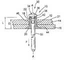
- FIG. 1is a partial cross-section of a blind rivet according to the present invention inserted through a workpiece
- FIG. 2is a cross-sectional view of the set rivet body of the rivet of FIG. 1 .
- a blind rivet assembly 10is shown inserted, but not set, in a preformed hole 12 extending between two work pieces 14 and 16 .
- the rivet assembly 10comprises a hollow tubular rivet body 18 having an enlarged counter-sunk flange 20 , this counter-sunk head tapering inwards along an axis A of the rivet body for complimentary receipt within a pre-formed counter-sunk region 44 of the hole 12 .
- the remote tail end 22 of the rivet body 18has a substantially flat end face extending perpendicular to the rivet axis A.
- the rivet body length Lis predetermined to be between 25% and 55% greater than the combined depth D of the two work pieces 14 and 16 .
- This depth Dis commonly referred to as the grip thickness of a blind rivet—defined as the thickness of material to be gripped by the set rivet. In the present embodiment, depth L is approximately 30% greater than depth D.
- the assembly 10is further provided with a mandrel 30 comprising a cylindrical mandrel stem having an enlarged head 34 at its blind end thereof which lies adjacent to the tail end 22 of the rivet body 18 .
- the mandrel stem 32is of substantially uniform cross-section area along its axial length and which diameter is substantially equal to the internal diameter of the tubular rivet body 18 so as to form a complimentary frictional fit therewith.
- the mandrel head 34has a maximum outer diameter defined by a radial wall 36 extending coaxial about the axis A and having an axial length of at least 1 mm. This minimum axial length of the mandrel head is required to provide appropriate strength to the head to alleviate the possibility of the mandrel head distorting, or “dishing” when it is subject to large stresses during the rivet setting operation and particularly when the circumference of the head is engaged with the rivet body to effect deformation thereof (as described below).
- This wall 36is greater than the maximum outer diameter of the rivet body so as to be at least 4% greater than the body diameter, but no greater than 9% thereof.
- the shoulder 38 of the mandrel headextending between the outer wall 36 and the mandrel stem, is axially inclined to form a substantially uniform conical surface which has a preferred angle of inclination, relative to the axis A, of 100°, although this angle of conical angular inclination can lie between the ranges of 91 and 110° to remain within acceptable operational parameters.
- This angular rangehas been determined to be appropriate for effecting the required deformation of the rivet during setting.
- the remote end of the mandrel headis also provide with a conical surface about axis A to act as an alignment mechanism for the assembly 10 , whereby the inclined surfaces thereof help align the assembly with the hole 12 as it is being inserted therein.
- the mandrel head diameteris required to be at least 4% greater than the outer diameter of the rivet body to alleviate this head being pulled into the body during the setting operation, which could prevent the head being ejected after setting.
- this diametermust not exceed 9% greater than the rivet body otherwise too large a hole will be required through the workpieces to allow the rivet to pass therethrough, making the filling of this hole difficult during setting (possibly leaving the set rivet loosely set) or the closer the hole diameter is to the diameter of the flange the risk of failure of the set rivet increases.
- the mandrel stem 32is provided with a preformed weakened region 42 immediately adjacent this conical surface 38 .
- this weakened region 42is formed as a narrowed portion of the stem resulting from squaring off the stem diameter to provide four flats about the diameter so as to present a substantially square cross-sectional area immediately adjacent the head being thinner, and hence weaker, than the main mandrel stem.
- the weakened portioncould result from two or more diametrically opposed indentations or even a circumferential groove. What is important here is that such weakened portion be immediately adjacent the mandrel head.
- the mandrel head 34has a diameter greater than the rivet body 18 , it is essential that the preformed hole 12 be of a diameter at least equal to that of the maximum mandrel head diameter and is usually formed to be 10% greater than the maximum diameter of the body (since the maximum diameter of the head is limited to 9% greater than the maximum diameter of the body).
- the hole 12can be formed to have a diameter of between 9% and 15% greater diameter than that of the maximum body diameter, dependent on the exact diameter ratio of the mandrel head to rivet body.
- the blind rivet system utilising a rivet according to the present inventionwill be compatible with standard hole sizes made with existing standard size drill bits (i.e. the rivet body diameter being such that the holes are 10% greater in diameter) although different size rivets could also be produced but requiring specific hole forming tools (drill bit) which will be of appropriate diameter to use with such rivets.
- the preformed hole 12whilst having a counter-sunk region 44 to accommodate the counter-sunk head 20 of the rivet body, will also have formed on the blind side region 21 of the workpieces (i.e. the inner side or that side opposite to the setting tool) a conical counter-sunk region 46 extending about the periphery of the hole.
- the rivet assembly 10may be set using a conventional blind rivet setting tool (not shown) which comprises a nose portion for restraining the rivet body flange (or head) 20 in solid abutment with the work piece 16 , whilst having a displaceable jaw mechanism for clamping the mandrel stem 32 and exerting a setting force F in the direction shown substantially by the arrow F in FIG. 1 .
- a conventional blind rivet setting tool(not shown) which comprises a nose portion for restraining the rivet body flange (or head) 20 in solid abutment with the work piece 16 , whilst having a displaceable jaw mechanism for clamping the mandrel stem 32 and exerting a setting force F in the direction shown substantially by the arrow F in FIG. 1 .
- the application of the setting force Fdraws the mandrel head into engagement with the flat surface of tail end portion 22 of the rivet body which, due to its conical shoulder 38 , exerts a setting force having a first component extending in an axial direction and which serves to compress the rivet body 18 towards the rivet flange 20 , resulting in radial expansion of the compressed (reduced length) rivet body so as to fill the enlarged hole 12 (this radial expansion being outwardly, due to the mandrel stem being maintained through the body 18 ).
- the conical shoulder 38also provides a secondary force component perpendicular to the conical surface of the such 38 which serves to deform the tail end 22 of the rivet body radially and conically outwards so that the mandrel head 34 does not substantially enter this shortened rivet body which, due to the axial length of the walls 36 (and the restricted length of the rivet body) is also unable to encompass and surround the mandrel head 34 . Rather, some of the material of tail end 22 of the rivet 18 is partially displaced axially towards the rivet head 20 with the remaining material of the rivet body in this tail end region forming a considerably thinned conical outer wall ( FIG.
- the resultant set blind rivetis shown in FIG. 2 having a compressed axial length L 2 , substantially equal to the grip thickness D, whereby the axially displaced rivet body material has been squeezed into the enlarged hole 12 to provide a rivet body having an increased body thickness 18 ′ in this region and which has a substantially conical, cup-shaped tail end 22 ′ formed into the counter-sunk region 46 of the preformed hole 12 .
- a substantially rigid rivet jointis formed which does not extend substantially proud of the blind side of the work piece 14 .
- the angular setting range of the conical shoulderhas been determined so that the appropriate deformation forces can be applied to compress and conically deform the rivet body in the manner described above. If the angle of this conical surface was greater than 110 degrees then there would be a risk that insufficient axial force would be applied during setting and that the head could be pulled into the rivet body. If this angle was less than 90 degrees then there would be no angular force component to effect conical deformation of the tail end of the rivet and the mandrel head is likely to be ejected without the rivet being correctly set.
- the rivet body head 20is shown to be counter-sunk so that this head 20 is also maintained flush with the outer work piece 16 once set, although this feature is optional and it will be appreciated that the current invention may utilize a conventional blind rivet which does not use a counter-sunk head.
- the importance of providing the length L within the predefined ranges discussed aboveis to provide sufficient material of the rivet body to allow appropriate deformation of the rivet body to fill the enlarged hole 12 after setting and to form a sufficiently robust set-end of the rivet that will resist any applied tensile loading on that joint, but not to result in excess rivet body material which cannot be accommodated by the counter-sunk region 46 of the hole 12 and may project beyond the blind side of the workpiece.
Landscapes
- Engineering & Computer Science (AREA)
- General Engineering & Computer Science (AREA)
- Mechanical Engineering (AREA)
- Insertion Pins And Rivets (AREA)
- Connection Of Plates (AREA)
Abstract
Description
This is a continuation application of U.S. Ser. No. 11/652,962, filed on Jan. 12, 2007, issued as U.S. Pat. No. 7,650,681, which is a divisional of U.S. Ser. No. 10/430,742, filed May 6, 2003, which claims priority to Great Britain Application No. 0210463.6, filed May 8, 2002, all of which are incorporated by reference herein.
The present invention is directed towards a blind rivet and more particularly to a blind rivet of the head break type whereby a mandrel head is ejected from the rivet body after setting.
Conventional blind rivets comprise an outer tubular shell or body having an enlarged flange at one end, together with a mandrel associated therewith, such mandrel comprising a cylindrical stem extending through the tubular rivet body so as to be coaxial therewith, the stem having a radially enlarged head at one end for engagement with an end face (tail end) of the rivet body remote from the enlarged flange. The blind rivet is then passed through a preformed hole in a workpiece until the flange engages with the edge of the hole and is held in engagement therewith during a setting operation. During setting, the remote end of the rivet, which is disposed inwardly of the work pieces (the blind side), is then compressed towards the flange by drawing the mandrel stem, and hence the mandrel head, back towards the flange, whereby the deformed portion of the rivet body compresses the work piece therebetween with the flange itself.
Of this type of blind rivet there are two main types. A break stem type blind rivet relies on the mandrel head entering the tail end of the rivet body and being pulled through the rivet body so as to be encapsulated thereby, until the mandrel head meets resistance as the expanded rivet body engages the blind side of the work pieces, whereby the subsequent increase in load on the mandrel stem causes this stem to break at a predefined weakened region so that the mandrel head is retained within the rivet body to form an expanded portion or bulge of the rivet body on the blind side of the work piece thereby compressing the work pieces between this enlarged region and the flange.
Alternatively, a break head type blind rivet relies upon the mandrel head being ejected following setting. In this type of blind rivet, the mandrel head has an abrupt change of section between the mandrel stem and the mandrel head to present a shoulder portion which engages the tail end of the blind rivet to exert a substantially axial force thereon thereby compressing and deforming the end of the rivet against the blind side of the work piece to form a flattened bulge between which the work pieces are again compressed against the flange. Here again a weakened region of the stem will again break, but since the mandrel head has not being drawn into the rivet body it is simply ejected away therefrom when the stem breaks due to the high reaction force between the deformed rivet body and the head.
However, in both these conventional types of blind rivet, a defined or enlarged section of the blind rivet is maintained on the blind side of the work piece presenting a projection which may limit the available workspace on the blind side of the work pieces. This is particularly relevant in the use of blind rivets to manufacture small cabinets, such as those used in the computer industry, whereby the internal projection of a set blind rivet may interfere with the placement of components within such cabinets.
It is therefore an object of the current invention to provide an improved blind rivet which alleviates the aforementioned problems.
According to the present invention there is now provided a blind rivet comprising an axially extending hollow tubular body having a tail end face at one end, and a pre-formed radially enlarged flange at the other end, the rivet further comprising a mandrel having a stem which extends co-axially through the tubular body and having an enlarged head adjacent the tail end of the body, this head having an outer diameter greater than an inner diameter of the body, wherein the mandrel has a uniform conical shoulder extending between the outer diameter of the head and the stem, the stem being further provided with a weakened region immediately adjacent this conical shoulder. Preferably the angle of this conical surface will be inclined at an angle between 91 and 110° to the axis will usually lie between 98 and 102°. Ideally, this angle will be at 100°. The use of such a conical surface to form a conical shoulder at these angles has been found to transmit a force, as the mandrel head is drawn into the rivet body, which has an axial component serving to compress the rivet body and also has a axially inclined component which serves to deform the tail end face of the rivet body conically outwards of its axis.
It is also preferred that the head diameter of the mandrel head is between 4% and 9% greater than an outer diameter of the tubular rivet body. For this reason, the rivet is intended to be inserted into a preformed hole extending through a workpiece/s which must have a diameter greater than this maximum head diameter and which is usually provided to have adiameter 10% greater than the body diameter. However, the hole diameter may lie in a range of 9% and 15% greater than the body diameter, dependent on the head diameter. This increased diameter of the head alleviates the possibility of the head being drawn into the rivet body during setting.
Furthermore, it is preferred that the mandrel head has an outer cylindrical diameter, usually co-axial with the rivet body, having an axial length of at least 1 mm, again to alleviate the possibility of the conically deformed body encompassing the mandrel head during the setting operation and, further, to prevent the head from becoming distorted (or “dished”) under the large loads applied thereto during a setting operation.
It is also preferred that the axial length of the rivet body will be between 25% and 55% greater than the grip thickness of such rivet, the grip thickness being defined as the combined thickness of the work pieces being joined together by this rivet and hence the thickness to be gripped thereby. This predefined rivet body length ensures that there is sufficient rivet body material to form an appropriate rivet joint and to flow into the preformed hole in the workpieces without resulting in excess rivet body material projecting excessively from the blind side of the connected work pieces once set.
Further according to the present invention there is also provided a method of fastening together at least two work pieces using a blind rivet, which method comprises the steps of selecting an axially extending blind rivet having a body with a length between 25% and 55% greater than the combined thickness of the at least two work pieces, the body also having a known outer diameter, then, pre-forming a hole through the workpieces, which hole having a diameter between 9% and 15% greater than the outer diameter of the rivet body, and subsequently inserting the blind rivet through this hole; this method then provides the step of applying an axial setting force to the rivet body by use of a mandrel head having a conical shoulder, whereby this setting force has a first axial component which is exerted in the axial direction to compress the rivet body into the hole and a second annular component to deform the rivet body conically outwards of its axis. Furthermore, it is preferred that the hole forming step comprises providing the blind side of the hole with a counter-sunk region so that the conical deformation of the rivet body is deformed into the counter-sunk region of the hole, so as not to project substantially proud of the blind side of the workpiece.
Preferably, this method will comprise the selecting and inserting of a blind rivet according to the present invention and as described above.
The preferred embodiment of the present invention will now be described, by way of example only, with reference to the accompanying, illustrative drawings in which:
Referring now toFIG. 1 , ablind rivet assembly 10 is shown inserted, but not set, in apreformed hole 12 extending between twowork pieces rivet assembly 10 comprises a hollowtubular rivet body 18 having an enlargedcounter-sunk flange 20, this counter-sunk head tapering inwards along an axis A of the rivet body for complimentary receipt within apre-formed counter-sunk region 44 of thehole 12.
Theremote tail end 22 of therivet body 18, axially opposed to theflange 20, has a substantially flat end face extending perpendicular to the rivet axis A. The rivet body length L is predetermined to be between 25% and 55% greater than the combined depth D of the twowork pieces assembly 10 is further provided with amandrel 30 comprising a cylindrical mandrel stem having an enlargedhead 34 at its blind end thereof which lies adjacent to thetail end 22 of therivet body 18. Themandrel stem 32 is of substantially uniform cross-section area along its axial length and which diameter is substantially equal to the internal diameter of the tubularrivet body 18 so as to form a complimentary frictional fit therewith.
Themandrel head 34 has a maximum outer diameter defined by aradial wall 36 extending coaxial about the axis A and having an axial length of at least 1 mm. This minimum axial length of the mandrel head is required to provide appropriate strength to the head to alleviate the possibility of the mandrel head distorting, or “dishing” when it is subject to large stresses during the rivet setting operation and particularly when the circumference of the head is engaged with the rivet body to effect deformation thereof (as described below).
The diameter of thiswall 36 is greater than the maximum outer diameter of the rivet body so as to be at least 4% greater than the body diameter, but no greater than 9% thereof.
Theshoulder 38 of the mandrel head, extending between theouter wall 36 and the mandrel stem, is axially inclined to form a substantially uniform conical surface which has a preferred angle of inclination, relative to the axis A, of 100°, although this angle of conical angular inclination can lie between the ranges of 91 and 110° to remain within acceptable operational parameters. This angular range has been determined to be appropriate for effecting the required deformation of the rivet during setting.
The remote end of the mandrel head is also provide with a conical surface about axis A to act as an alignment mechanism for theassembly 10, whereby the inclined surfaces thereof help align the assembly with thehole 12 as it is being inserted therein.
The mandrel head diameter is required to be at least 4% greater than the outer diameter of the rivet body to alleviate this head being pulled into the body during the setting operation, which could prevent the head being ejected after setting. However, this diameter must not exceed 9% greater than the rivet body otherwise too large a hole will be required through the workpieces to allow the rivet to pass therethrough, making the filling of this hole difficult during setting (possibly leaving the set rivet loosely set) or the closer the hole diameter is to the diameter of the flange the risk of failure of the set rivet increases.
Furthermore, themandrel stem 32 is provided with a preformed weakenedregion 42 immediately adjacent thisconical surface 38. As is conventional for blind rivets, this weakenedregion 42 is formed as a narrowed portion of the stem resulting from squaring off the stem diameter to provide four flats about the diameter so as to present a substantially square cross-sectional area immediately adjacent the head being thinner, and hence weaker, than the main mandrel stem. Alternatively, the weakened portion could result from two or more diametrically opposed indentations or even a circumferential groove. What is important here is that such weakened portion be immediately adjacent the mandrel head.
Since themandrel head 34 has a diameter greater than therivet body 18, it is essential that thepreformed hole 12 be of a diameter at least equal to that of the maximum mandrel head diameter and is usually formed to be 10% greater than the maximum diameter of the body (since the maximum diameter of the head is limited to 9% greater than the maximum diameter of the body). However, thehole 12 can be formed to have a diameter of between 9% and 15% greater diameter than that of the maximum body diameter, dependent on the exact diameter ratio of the mandrel head to rivet body. Usually the blind rivet system utilising a rivet according to the present invention will be compatible with standard hole sizes made with existing standard size drill bits (i.e. the rivet body diameter being such that the holes are 10% greater in diameter) although different size rivets could also be produced but requiring specific hole forming tools (drill bit) which will be of appropriate diameter to use with such rivets.
Furthermore, thepreformed hole 12, whilst having acounter-sunk region 44 to accommodate thecounter-sunk head 20 of the rivet body, will also have formed on theblind side region 21 of the workpieces (i.e. the inner side or that side opposite to the setting tool) aconical counter-sunk region 46 extending about the periphery of the hole.
Once therivet assembly 10 has been inserted through thispreformed hole 12 it may be set using a conventional blind rivet setting tool (not shown) which comprises a nose portion for restraining the rivet body flange (or head)20 in solid abutment with thework piece 16, whilst having a displaceable jaw mechanism for clamping themandrel stem 32 and exerting a setting force F in the direction shown substantially by the arrow F inFIG. 1 .
The application of the setting force F draws the mandrel head into engagement with the flat surface oftail end portion 22 of the rivet body which, due to itsconical shoulder 38, exerts a setting force having a first component extending in an axial direction and which serves to compress therivet body 18 towards therivet flange 20, resulting in radial expansion of the compressed (reduced length) rivet body so as to fill the enlarged hole12 (this radial expansion being outwardly, due to the mandrel stem being maintained through the body18). Theconical shoulder 38 also provides a secondary force component perpendicular to the conical surface of the such38 which serves to deform thetail end 22 of the rivet body radially and conically outwards so that themandrel head 34 does not substantially enter this shortened rivet body which, due to the axial length of the walls36 (and the restricted length of the rivet body) is also unable to encompass and surround themandrel head 34. Rather, some of the material oftail end 22 of therivet 18 is partially displaced axially towards therivet head 20 with the remaining material of the rivet body in this tail end region forming a considerably thinned conical outer wall (FIG. 2 ) which is displaced into thecounter-sunk region 46 of thehole 12 so as not to project externally of the secured workpieces. Thus the combination of theconical shoulder 38 of the mandrel and the countersunkregion 46 serve to provide such conical spreading of the tail end of the body.
Continued axial displacement of the mandrel in direction F results in an increased resistance force encountered by themandrel head 34 as it encounters theworkpiece 14, and which subsequently prevents further displacement of the mandrel head. Continued application of the setting force F the increases the stress on the mandrel stem in a conventional manner until resulting failure of themandrel stem 32 at the weakenedregion 42. The resultant re-action force between therivet head 34 and therivet body 18 causing ejection of therivet head 34 therefrom.
The resultant set blind rivet is shown inFIG. 2 having a compressed axial length L2, substantially equal to the grip thickness D, whereby the axially displaced rivet body material has been squeezed into theenlarged hole 12 to provide a rivet body having an increasedbody thickness 18′ in this region and which has a substantially conical, cup-shapedtail end 22′ formed into thecounter-sunk region 46 of the preformedhole 12. In this manner, a substantially rigid rivet joint is formed which does not extend substantially proud of the blind side of thework piece 14.
Furthermore, the angular setting range of the conical shoulder has been determined so that the appropriate deformation forces can be applied to compress and conically deform the rivet body in the manner described above. If the angle of this conical surface was greater than 110 degrees then there would be a risk that insufficient axial force would be applied during setting and that the head could be pulled into the rivet body. If this angle was less than 90 degrees then there would be no angular force component to effect conical deformation of the tail end of the rivet and the mandrel head is likely to be ejected without the rivet being correctly set.
In this preferred embodiment, therivet body head 20 is shown to be counter-sunk so that thishead 20 is also maintained flush with theouter work piece 16 once set, although this feature is optional and it will be appreciated that the current invention may utilize a conventional blind rivet which does not use a counter-sunk head.
The importance of providing the length L within the predefined ranges discussed above is to provide sufficient material of the rivet body to allow appropriate deformation of the rivet body to fill theenlarged hole 12 after setting and to form a sufficiently robust set-end of the rivet that will resist any applied tensile loading on that joint, but not to result in excess rivet body material which cannot be accommodated by thecounter-sunk region 46 of thehole 12 and may project beyond the blind side of the workpiece.
While the above detailed description describes the preferred embodiment of the present invention, it should be understood that the present invention is susceptible to modification, variation and alteration without deviating from the scope and fair meaning of the subjoined claims.
Claims (29)
1. A method of joining workpieces having a hole, the method comprising:
(a) using a blind rivet having a hollow central body segment, a preformed tool-side flange and a blind-side end;
(b) inserting the rivet body segment into the hole and the tool-side flange into a frusto-conical depression of a tool-side surface of the workpieces;
(c) applying an axial setting force to the rivet body by use of a mandrel head and a shoulder, the shoulder having a graduated cross-sectional diameter between a mandrel shaft and the head, the shaft operably extending through the rivet body segment;
(d) laterally expanding the blind-side end of the rivet into a frusto-conical depression in a blind-side surface of the workpieces, all of the blind-side and tool-side ends of the rivet being substantially flush with or below the adjacent outer workpiece surfaces after setting;
(e) the workpiece hole being radially larger than the central body segment of the rivet prior to setting, and radially expanding the central body segment of the rivet to fill the workpiece hole during setting; and
(f) removing the mandrel head, shoulder and shaft from the blind rivet.
2. The method ofclaim 1 wherein the rivet body segment and flange have a continuous and uniformly sized bore therethrough, at least prior to rivet setting.
3. The method ofclaim 1 wherein the rivet flange has a substantially conical outside shape.
4. The method ofclaim 1 wherein the rivet flange is pre-shaped into an enlarged configuration prior to rivet setting.
5. The method ofclaim 1 further comprising creating a bulbously curved outside surface adjacent the blind-side end during the laterally expanding step.
6. The method ofclaim 1 further comprising intentionally breaking the mandrel shaft during rivet setting.
7. The method ofclaim 1 further comprising inserting the mandrel shaft and rivet body segment together into the hole of the workpieces, the shaft snugly fitting within the rivet body segment during the insertion.
8. The method ofclaim 1 further comprising setting the blind rivet so that a tool-facing surface and an opposite blind surface of the blind rivet are substantially parallel to each other and to the corresponding tool and blind-side surfaces of the workpieces after the setting.
9. The method ofclaim 1 further comprising inserting the blind rivet into the workpieces which are part of a computer cabinet.
10. The method ofclaim 1 further comprising making the depression in the tool-side surface of the workpieces and making the depression in the blind-side surface of the workpieces.
11. The method ofclaim 1 further comprising preventing the mandrel head from distorting during setting.
12. A method of joining workpieces, the method comprising:
(a) inserting a blind rivet into a hole in the workpieces;
(b) inserting a substantially conical tool-side flange of the rivet into a substantially conical countersink in a tool-side outer surface of the workpieces;
(c) setting the blind rivet to the workpieces by deforming a blind-end of the rivet into a substantially conical countersink in a blind-side outer surface of the workpieces;
(d) causing a through-bore in the rivet to be unobstructed after the setting; and
(e) the workpiece hole being radially larger than the central body segment of the rivet prior to setting, and radially expanding a central body segment of the rivet to fill the workpiece hole during setting.
13. The method ofclaim 12 further comprising creating a substantially bulbously curved outside surface adjacent a blind-side end during the setting.
14. The method ofclaim 12 further comprising inserting a mandrel and rivet body segment together into the hole of the workpieces, the mandrel snugly fitting within the rivet body segment during the insertion.
15. The method ofclaim 12 further comprising setting the blind rivet so that a tool-facing surface and an opposite blind surface of the blind rivet are substantially parallel to each other and to corresponding tool and blind-side surfaces of the workpieces.
16. The method ofclaim 12 further comprising inserting the blind rivet into the workpieces which are part of a computer cabinet.
17. The method ofclaim 12 further comprising compressing and expanding the blind-end of the rivet by pulling on a mandrel, the mandrel including an enlarged head adjacent to the blind-end, an elongated stem and a tapered shoulder located between the head and the stem.
18. The method ofclaim 12 further comprising intentionally breaking a mandrel attached to the blind rivet during the setting.
19. The method ofclaim 12 further comprising making the countersink in the tool-side outer surface of the workpieces and making the countersink in the blind-side outer surface of the workpieces.
20. The method ofclaim 12 further comprising setting the blind rivet by moving a mandrel through the through-bore in the blind rivet, and preventing a head of the mandrel from distorting during setting.
21. A method of joining using a rivet, the method comprising:
(a) inserting a mandrel and a blind rivet body together into a hole of computer workpieces;
(b) securing a pre-enlarged tool-side flange of the blind rivet body entirely into a countersink in a tool-side surface of the computer workpieces;
(c) securing a blind-end of the blind rivet body into a countersink in a blind-side surface of the computer workpieces;
(d) applying axial and lateral forces to deform the blind-end of the blind rivet body to assist in the securing steps; and
(e) preventing the blind rivet body from fixedly encompassing a head of the mandrel during setting, and allowing a bore of the rivet to be unobstructed after setting.
22. The method ofclaim 21 further comprising creating a substantially curved and bulbous outside surface adjacent the blind-side end during the securing.
23. The method ofclaim 21 further comprising setting the tool-side flange and blind-end of the rivet substantially flush with respective outside surfaces of the computer workpieces.
24. The method ofclaim 21 further comprising intentionally breaking a mandrel attached to the blind rivet during setting.
25. The method ofclaim 21 further comprising outwardly expanding the blind-end of the blind rivet with a tapered shoulder on the mandrel, and inserting a substantially pointed blind-end of the mandrel into the hole in the computer workpieces prior to inserting the blind rivet into the hole.
26. The method ofclaim 21 wherein the countersinks each have a substantially conical shape.
27. The method ofclaim 21 further comprising making the countersink in the tool-side surface of the workpieces and making the countersink in the blind-side surface of the workpieces.
28. The method ofclaim 21 further comprising preventing the mandrel head from distorting during setting.
29. A method of joining workpieces having a hole, the method comprising:
(a) providing a depression in a tool-side surface of the workpieces and providing a depression in a blind-side surface of the workpieces;
(b) using a blind rivet having a body segment between a tool-side flange and a blind-side end, the flange including a substantially conical outside surface pre-shaped prior to rivet setting;
(c) providing a shaft of a mandrel in the rivet body segment of the blind rivet prior to insertion of the blind rivet into the hole of the workpieces, the shaft being located within the rivet body segment in a friction-fit manner during the rivet-to-hole insertion;
(d) inserting the tool-side flange into the depression of the tool-side surface of the workpieces;
(e) applying an axial setting force to the rivet body by use of a head and a shoulder of the mandrel, the shoulder having a graduated cross-sectional diameter between a mandrel shaft and the head;
(f) laterally expanding the blind-side end of the rivet into the depression in the blind-side surface of the workpieces, all of the blind-side end and tool-side flange of the rivet being substantially flush with or below the adjacent outer workpiece surfaces after setting;
(g) the workpiece hole being radially larger than the body segment of the blind rivet prior to setting, and radially expanding the body segment of the rivet to fill the workpiece hole during setting;
(h) preventing the mandrel head from distorting during setting;
(i) intentionally breaking the mandrel shaft during rivet setting; and
(j) removing the mandrel head from the blind rivet substantially after the blind rivet is set in the workpiece hole.
Priority Applications (1)
| Application Number | Priority Date | Filing Date | Title |
|---|---|---|---|
| US12/687,427US7937821B2 (en) | 2002-05-08 | 2010-01-14 | Blind rivet method |
Applications Claiming Priority (5)
| Application Number | Priority Date | Filing Date | Title |
|---|---|---|---|
| GB0210463.6 | 2002-05-08 | ||
| GB0210463AGB2388412A (en) | 2002-05-08 | 2002-05-08 | Blind rivet |
| US10/430,742US8328483B2 (en) | 2002-05-08 | 2003-05-06 | Blind rivet |
| US11/652,962US7650681B2 (en) | 2002-05-08 | 2007-01-12 | Blind rivet method |
| US12/687,427US7937821B2 (en) | 2002-05-08 | 2010-01-14 | Blind rivet method |
Related Parent Applications (1)
| Application Number | Title | Priority Date | Filing Date |
|---|---|---|---|
| US11/652,962ContinuationUS7650681B2 (en) | 2002-05-08 | 2007-01-12 | Blind rivet method |
Publications (2)
| Publication Number | Publication Date |
|---|---|
| US20100139076A1 US20100139076A1 (en) | 2010-06-10 |
| US7937821B2true US7937821B2 (en) | 2011-05-10 |
Family
ID=9936229
Family Applications (3)
| Application Number | Title | Priority Date | Filing Date |
|---|---|---|---|
| US10/430,742Expired - Fee RelatedUS8328483B2 (en) | 2002-05-08 | 2003-05-06 | Blind rivet |
| US11/652,962Expired - LifetimeUS7650681B2 (en) | 2002-05-08 | 2007-01-12 | Blind rivet method |
| US12/687,427Expired - LifetimeUS7937821B2 (en) | 2002-05-08 | 2010-01-14 | Blind rivet method |
Family Applications Before (2)
| Application Number | Title | Priority Date | Filing Date |
|---|---|---|---|
| US10/430,742Expired - Fee RelatedUS8328483B2 (en) | 2002-05-08 | 2003-05-06 | Blind rivet |
| US11/652,962Expired - LifetimeUS7650681B2 (en) | 2002-05-08 | 2007-01-12 | Blind rivet method |
Country Status (12)
| Country | Link |
|---|---|
| US (3) | US8328483B2 (en) |
| EP (1) | EP1361370B1 (en) |
| JP (2) | JP4542751B2 (en) |
| CN (2) | CN1333175C (en) |
| AT (1) | ATE300679T1 (en) |
| DE (1) | DE60301083T2 (en) |
| ES (1) | ES2246439T3 (en) |
| GB (1) | GB2388412A (en) |
| MY (1) | MY137832A (en) |
| PL (1) | PL206141B1 (en) |
| TW (2) | TWI341369B (en) |
| WO (1) | WO2003095848A1 (en) |
Cited By (2)
| Publication number | Priority date | Publication date | Assignee | Title |
|---|---|---|---|---|
| US9334893B2 (en) | 2010-06-08 | 2016-05-10 | Newfrey Llc | Blind rivet and fastening arrangement with a blind rivet |
| US10087969B2 (en) | 2013-05-02 | 2018-10-02 | Ornit Agriculture Industry Business And Management Agricultural Cooperative Association Ltd. | Blind rivet |
Families Citing this family (33)
| Publication number | Priority date | Publication date | Assignee | Title |
|---|---|---|---|---|
| GB2388412A (en) | 2002-05-08 | 2003-11-12 | Emhart Llc | Blind rivet |
| JP4468711B2 (en)* | 2004-02-16 | 2010-05-26 | ポップリベット・ファスナー株式会社 | Blind rivet |
| US7722303B2 (en)* | 2005-02-11 | 2010-05-25 | Newfrey Llc | Frangible blind rivet |
| US8449234B2 (en)* | 2007-01-16 | 2013-05-28 | Harry E. Taylor | Blind rivet |
| US8096742B2 (en)* | 2007-08-03 | 2012-01-17 | Newfrey Llc | Blind rivet |
| US7824141B2 (en)* | 2007-08-03 | 2010-11-02 | Newfrey Llc | Blind rivet |
| JP2010094713A (en)* | 2008-10-17 | 2010-04-30 | Nec Computertechno Ltd | Method and structure for fastening plate material |
| JP2010144806A (en)* | 2008-12-17 | 2010-07-01 | Nippon Pop Rivets & Fasteners Ltd | Fastening member and its mounting method |
| DE102009039936A1 (en)* | 2009-08-24 | 2011-04-07 | Newfrey Llc, Newark | Punch rivet, method of producing a punched rivet joint and workpiece assembly |
| JP2011157996A (en)* | 2010-01-29 | 2011-08-18 | Nippon Pop Rivets & Fasteners Ltd | Blind rivet |
| TW201137245A (en)* | 2010-04-23 | 2011-11-01 | bing-song Chen | Method of manufacturing rivet with single riveting bolt and multiple specifications and structure thereof |
| US8696719B2 (en) | 2010-06-03 | 2014-04-15 | Tarsus Medical Inc. | Methods and devices for treating hallux valgus |
| DE102010051039A1 (en)* | 2010-11-11 | 2012-05-16 | Daimler Ag | Height-adjustable safety steering column assembly |
| US9138219B2 (en) | 2010-12-29 | 2015-09-22 | Tarsus Medical Inc. | Methods and devices for treating a syndesmosis injury |
| JP6045805B2 (en)* | 2012-03-26 | 2016-12-14 | 須藤 二三男 | Chair frame structure |
| EP2689867A1 (en)* | 2012-07-27 | 2014-01-29 | GESIPA Blindniettechnik GmbH | Connection element and setting device for a connection element |
| DE202013012734U1 (en)* | 2013-12-11 | 2018-12-13 | Newfrey Llc | Punch rivet and punched rivet connection |
| FR3019864B1 (en)* | 2014-04-14 | 2017-04-07 | Snecma | RIVETE ASSEMBLY AND METHOD OF MANUFACTURING THE SAME |
| PL409401A1 (en) | 2014-09-08 | 2016-03-14 | Newtech Spółka Z Ograniczoną Odpowiedzialnością | Device, preferably for mechanization of riveting processes of internal combustion turbines |
| PL409400A1 (en) | 2014-09-08 | 2016-03-14 | Newtech Spółka Z Ograniczoną Odpowiedzialnością | Method for removing rivets, preferably for the magnetic-pulse system for hot riveting |
| PL409399A1 (en) | 2014-09-08 | 2016-03-14 | Newtech Spółka Z Ograniczoną Odpowiedzialnością | Magnetic-pulse system for hot riveting |
| DE102015120278A1 (en) | 2015-11-24 | 2017-05-24 | Newfrey Llc | Blind rivet assembly and blind riveting method |
| CN106938305A (en)* | 2016-01-05 | 2017-07-11 | 中兴通讯股份有限公司 | From riveting connection method and from riveting attachment means |
| CN105626647A (en)* | 2016-03-11 | 2016-06-01 | 无锡安士达五金有限公司 | Detachable expansion-type rivet |
| CN106050845A (en)* | 2016-07-26 | 2016-10-26 | 中国电子科技集团公司第十研究所 | Method for connecting two thin plates by using countersunk riveting bushing |
| FR3068541B1 (en)* | 2017-06-28 | 2019-07-19 | Valeo Equipements Electriques Moteur | PARTS ASSEMBLY AND METHOD FOR MANUFACTURING SUCH ASSEMBLY |
| US11384783B2 (en) | 2017-10-31 | 2022-07-12 | Allfast Fastening Systems | Chip break bolt head |
| US11098742B2 (en) | 2017-12-27 | 2021-08-24 | Allfast Fastening Systems | Tacking fastener |
| DE102019117086A1 (en)* | 2019-06-25 | 2020-12-31 | Profil Verbindungstechnik Gmbh & Co. Kg | Fastening unit |
| CN114001098B (en)* | 2021-11-04 | 2023-12-08 | 浙江翎天科技有限公司 | Hub bearing production process |
| US12420341B2 (en)* | 2021-12-03 | 2025-09-23 | Howmet Aerospace Inc. | Blind fastener |
| CN114992201A (en)* | 2022-05-27 | 2022-09-02 | 中国航空工业集团公司沈阳飞机设计研究所 | a fastening structure |
| CN116630306B (en)* | 2023-07-19 | 2023-10-20 | 成都信息工程大学 | Defect detection method and device for aircraft semi-circular head rivet |
Citations (138)
| Publication number | Priority date | Publication date | Assignee | Title |
|---|---|---|---|---|
| US1979686A (en) | 1929-11-13 | 1934-11-06 | Hall & Kay Ltd | Metal socket, bush, ferrule, rivet, and the like |
| US1996128A (en) | 1933-11-21 | 1935-04-02 | Dardelet Threadlock Corp | Fastener |
| US2146461A (en) | 1937-01-06 | 1939-02-07 | Aviat Developments Ltd | Method of riveting |
| US2183543A (en) | 1937-06-21 | 1939-12-19 | Carl W Cherry | Rivet and method of applying the same |
| US2328023A (en) | 1942-05-16 | 1943-08-31 | Bocjl Corp | Blind rivet |
| US2366965A (en) | 1939-08-18 | 1945-01-09 | Aviat Developments Ltd | Tubular rivet |
| US2371423A (en) | 1943-04-17 | 1945-03-13 | B F B Engineers Inc | Mandrel extrusion rivet |
| US2371452A (en) | 1944-03-14 | 1945-03-13 | Jr Milton H Lees | Rivet |
| US2384321A (en) | 1944-03-29 | 1945-09-04 | Jr Milton H Lees | Rivet construction |
| GB642664A (en) | 1947-05-23 | 1950-09-06 | Aviat Developments Ltd | Improvements in or relating to feeding appliances |
| US2546602A (en) | 1945-05-14 | 1951-03-27 | Cherry Rivet Company | Rivet with self-locking mandrel |
| US2774098A (en) | 1952-08-19 | 1956-12-18 | Arthur J Tieri | Ophthalmic mounting hinge |
| US2885798A (en) | 1957-12-23 | 1959-05-12 | United Shoe Machinery Corp | Shoes, heels and lift attachments therefor |
| US3047181A (en) | 1956-02-28 | 1962-07-31 | Hans Georg Biermann | Rivet combination |
| US3055255A (en) | 1957-03-25 | 1962-09-25 | Avdel Ltd | Blind rivet with internal mandrel supporting element |
| US3144158A (en) | 1961-06-13 | 1964-08-11 | Gobin Daude | Device for setting rivets in a wall whitch is accessible on one side only |
| US3148578A (en) | 1961-10-16 | 1964-09-15 | Townsend Company | Rivet and method of riveting |
| GB1066033A (en) | 1963-08-30 | 1967-04-19 | Avdel Ltd | Improvements in or relating to blind rivet fastening devices |
| FR1494693A (en) | 1965-05-19 | 1967-09-08 | Olympic Screw & Rivet Corp | Blind rivets |
| US3390601A (en) | 1965-08-12 | 1968-07-02 | Avdel Ltd | Blind fastening devices |
| FR1553116A (en) | 1967-11-30 | 1969-01-10 | ||
| US3424051A (en) | 1967-03-20 | 1969-01-28 | Huck Mfg Co | Hollow fastener and plug assembly |
| US3438301A (en) | 1967-04-10 | 1969-04-15 | Emhart Corp | Hollow rivet and pull-stem assembly for blind fastening or the like |
| US3459447A (en) | 1966-12-13 | 1969-08-05 | Huck Mfg Co | Flush fastener for panel assembly including soft core material |
| US3460429A (en) | 1967-04-19 | 1969-08-12 | Jack La Torre | Expansible fastener with expander therefor |
| US3491649A (en) | 1967-08-09 | 1970-01-27 | Aerpat Ag | Rivets |
| GB1183049A (en) | 1966-09-16 | 1970-03-04 | Avdel Ltd | Riveting Apparatus |
| US3750518A (en) | 1972-06-07 | 1973-08-07 | Illinois Tool Works | Self-drilling blind rivet |
| US3835688A (en) | 1970-04-30 | 1974-09-17 | J King | Apparatus and method for sizing holes |
| US3837208A (en) | 1972-02-14 | 1974-09-24 | Avdel Ltd | Method and apparatus for blind riveting |
| US3915055A (en) | 1972-10-30 | 1975-10-28 | Lloyd Sylvester Binns | Blind rivet having counterbored sleeve head of double-angle configuration |
| US3922586A (en) | 1974-04-01 | 1975-11-25 | Ite Imperial Corp | Ground fault detecting power outlet |
| US3949535A (en) | 1973-01-17 | 1976-04-13 | King John O Jun | Coldworked joint held by seamless tubular member |
| US3975786A (en) | 1973-02-05 | 1976-08-24 | Textron, Inc. | Method of forming a rivet of titanium-columbium alloy |
| US4003288A (en) | 1969-07-28 | 1977-01-18 | Aerpat A.G. | Tubular rivet |
| US4044591A (en) | 1975-07-23 | 1977-08-30 | Usm Corporation | Blind rivet and improved method of blind riveting |
| GB1495592A (en) | 1974-01-18 | 1977-12-21 | Raymond A | Securing members |
| US4137817A (en) | 1972-04-17 | 1979-02-06 | Olympic Fastening Systems, Inc. | Blind rivet with recessed expanding head |
| US4164807A (en) | 1974-03-19 | 1979-08-21 | King John O Jun | Method of forming a coldworked joint |
| GB1572269A (en) | 1978-03-17 | 1980-07-30 | Advel Ltd | Jaw assembly for blind riveting apparatus |
| US4236429A (en) | 1976-12-30 | 1980-12-02 | Gernot Dolch | Blind rivet |
| US4261245A (en) | 1976-12-10 | 1981-04-14 | Usm Corporation | Fastener |
| US4388031A (en) | 1980-10-03 | 1983-06-14 | Rodgers Earl T | Blind fastener device |
| US4407619A (en) | 1979-09-20 | 1983-10-04 | Olympic Fastening Systems | Blind fastener with deformable clamping means |
| US4447944A (en) | 1982-06-16 | 1984-05-15 | The United States Of America As Represented By The Secretary Of The Navy | Method of forming a tubular rivet in fastening relation to a plurality of laminates |
| US4466048A (en) | 1980-10-21 | 1984-08-14 | B/K Patent Development Co., Inc. | Electrical shunts for integrated circuit applications |
| US4473914A (en) | 1982-09-30 | 1984-10-02 | Huck Manufacturing Company | Method and apparatus for manufacturing a stop and lock shoulder for a blind fastener sleeve |
| US4497603A (en) | 1982-06-28 | 1985-02-05 | Usm Corporation | Pull through blind rivet |
| US4507706A (en) | 1982-06-18 | 1985-03-26 | Paccar Inc. | Plug-in instrumentation system |
| US4541032A (en) | 1980-10-21 | 1985-09-10 | B/K Patent Development Company, Inc. | Modular electrical shunts for integrated circuit applications |
| US4541761A (en) | 1983-09-26 | 1985-09-17 | Usm Corporation | Easily removed blind rivet |
| US4585382A (en) | 1983-12-01 | 1986-04-29 | Usm Corporation | Easily removable rivet with tab |
| US4620825A (en) | 1983-12-03 | 1986-11-04 | Usm Corporation | Pull-type blind-riveting assemblies |
| US4659271A (en) | 1984-02-23 | 1987-04-21 | Monogram Industries, Inc. | Flush break blind fastener |
| DE3612501A1 (en) | 1986-04-14 | 1987-10-22 | Tucker Gmbh | Metal blind rivet |
| US4702655A (en) | 1985-08-27 | 1987-10-27 | Huck Manufacturing Company | Fastening system including an improved interference fit blind fastener and method of manufacture |
| EP0251700A2 (en) | 1986-06-26 | 1988-01-07 | Textron Inc. | Blind fastener with self-locking collar |
| US4736560A (en) | 1986-12-01 | 1988-04-12 | Engineered Construction Components (America) | Peel rivet |
| US4765010A (en) | 1985-07-12 | 1988-08-23 | Advel Limited | Method of making a stem for a self-plugging blind fastener |
| US4836728A (en) | 1983-11-15 | 1989-06-06 | Emhart Industries, Inc. | Blind-riveting assembly |
| US4858067A (en) | 1987-11-18 | 1989-08-15 | Crl Electronics, Inc. | Modular electronic control housing assembly |
| US4863325A (en) | 1982-09-28 | 1989-09-05 | Huck Manufacturing Company | Two piece blind fastener with lock spindle construction |
| US4893390A (en) | 1988-09-01 | 1990-01-16 | Snyder General Corporation | Method and expander for manufacturing a furnace heat exchanger and plate assembly |
| US4897003A (en) | 1988-02-12 | 1990-01-30 | Avdel Systems Limited | Blind rivet |
| US4904133A (en) | 1988-07-11 | 1990-02-27 | Textron Inc. | Fastener with integral locking means |
| US4909687A (en) | 1988-05-27 | 1990-03-20 | Avdel Systems Limited, A British Company | Blind rivet |
| US4929137A (en) | 1986-11-21 | 1990-05-29 | Dasmler-Benz AG | Safety arrangement for proving the unauthorized opening of a housing |
| US4958971A (en) | 1987-01-30 | 1990-09-25 | Avdel Limited | Break-stem blind rivet |
| US4969785A (en) | 1989-11-01 | 1990-11-13 | Textron, Inc. | Fastener mandrel and method |
| US5006024A (en) | 1990-03-05 | 1991-04-09 | George Siebol | Dual-lock blind fastener |
| US5035129A (en) | 1989-07-21 | 1991-07-30 | Avdel Systems Limited | Repetition riveting apparatus |
| DE4003136A1 (en) | 1990-02-02 | 1991-08-08 | Boellhoff & Co | Mandrel for closing blind rivet - has specially shaped transition surface between head and shank |
| US5044850A (en) | 1990-05-11 | 1991-09-03 | Avdel Corporation | Self plugging blind rivet |
| US5054977A (en) | 1990-09-18 | 1991-10-08 | Automatic Fastener Corporation | Self plugging blind rivet |
| US5167585A (en) | 1990-07-17 | 1992-12-01 | Emhart Inc. | Blind riveting assembly |
| US5252013A (en) | 1991-01-18 | 1993-10-12 | Avdel Systems Limited | Self-plugging blind rivet |
| US5259713A (en) | 1991-01-11 | 1993-11-09 | Emhart Inc. | Blind rivet nut with pulling mandrel |
| US5299667A (en) | 1989-07-22 | 1994-04-05 | Dunlop Limited, A British Company | Carbon composite laminated structure |
| US5320465A (en) | 1992-02-15 | 1994-06-14 | Emhart Inc. | Blind pin fixing |
| US5333980A (en) | 1993-07-15 | 1994-08-02 | Textron, Inc. | Buckling semi-solid rivet |
| US5359765A (en) | 1985-09-18 | 1994-11-01 | Ste Ateliers De La Haute-Garonne-Ets Auriol Et Cie | Rivet for composite material and composite material assembly process |
| US5378098A (en) | 1992-12-09 | 1995-01-03 | Textron Inc. | Hole filling blind rivet |
| US5403135A (en) | 1991-01-11 | 1995-04-04 | Emhart Inc. | Blind rivet nut with pulling mandrel |
| US5443344A (en) | 1994-09-12 | 1995-08-22 | Iowa State University Research Foundation, Inc. | Method and apparatus for attaching two members together from one side thereof |
| US5476350A (en) | 1993-10-28 | 1995-12-19 | Avdel Corporation - Systems Division | Slotted push-in rivet and method of riveting |
| US5496140A (en) | 1993-12-17 | 1996-03-05 | Gesipa Blindniettechnik Gmbh | Blind rivets and method for its manufacture |
| US5503510A (en) | 1993-08-27 | 1996-04-02 | Ornit Blind Rivets | Blind rivet |
| US5551817A (en) | 1993-06-04 | 1996-09-03 | Emhart Inc. | Fastener for attaching in one direction |
| US5569006A (en) | 1995-05-11 | 1996-10-29 | Textron, Inc. | Bulb fastener |
| US5645383A (en) | 1995-03-01 | 1997-07-08 | Emhart Inc. | Blind rivet |
| US5651172A (en) | 1990-01-26 | 1997-07-29 | Ste. Ateliers De La Haute-Garonne-Ets Auriol Et Cie | Process for the assembly of materials and riveting member for carrying out the process |
| US5658107A (en) | 1993-11-26 | 1997-08-19 | Emhart, Inc. | Blind rivet |
| US5689873A (en) | 1996-01-11 | 1997-11-25 | Allfast Fastening Systems, Inc. | Tacking fastener |
| US5741099A (en) | 1996-05-17 | 1998-04-21 | Asar Group, Inc. | Self tapping blind setting rivet assembly |
| US5743691A (en) | 1997-02-03 | 1998-04-28 | Textron Inc. | Clinch-type fastener member |
| US5759001A (en) | 1995-09-23 | 1998-06-02 | Emhart Inc. | Blind rivet |
| US5881989A (en) | 1997-03-04 | 1999-03-16 | Apple Computer, Inc. | Audio enclosure assembly mounting system and method |
| US5889648A (en) | 1997-07-25 | 1999-03-30 | Storage Technology Corporation | Seismic cabinet |
| US5890693A (en) | 1996-05-03 | 1999-04-06 | Citicorp Development Center, Inc. | Personal computer enclosure with peripheral device mounting system |
| US5915901A (en) | 1996-07-12 | 1999-06-29 | Asar Group, Inc. | Blind setting rivet assembly |
| US5960667A (en) | 1997-12-23 | 1999-10-05 | Emhart Inc. | Ball device for setting blind riverts |
| US5982610A (en) | 1998-05-27 | 1999-11-09 | Reltec Corporation | Multisided communication distribution cabinet having adjustable tie rod |
| US6004086A (en) | 1997-09-22 | 1999-12-21 | Avdel Verbindungselemente Gmbh | Breakable-stem blind rivet and apparatus for setting the same |
| US6007287A (en) | 1997-10-30 | 1999-12-28 | Mcdonnell Douglas Corporation | Deformable head fastener |
| US6042313A (en) | 1997-07-29 | 2000-03-28 | Richard Bergner Gmbh & Co. | Blind rivet |
| JP3048106B2 (en) | 1994-03-18 | 2000-06-05 | 株式会社富士通ゼネラル | Electric carpet |
| US6081984A (en) | 1995-01-31 | 2000-07-04 | Avdel Textron Limited | Method of fastening members of an assembly |
| US6171038B1 (en) | 1998-11-12 | 2001-01-09 | Textron Inc. | Tapered shank rivet |
| US6224310B1 (en) | 1996-11-28 | 2001-05-01 | Emhart Inc. | Blind rivet and method of making same |
| US20010005475A1 (en) | 1998-06-04 | 2001-06-28 | Robert Frigg | Blind rivet with fastener |
| US6254324B1 (en) | 1999-02-19 | 2001-07-03 | Emhart Inc. | Blind rivet |
| US6276050B1 (en) | 1998-07-20 | 2001-08-21 | Emhart Inc. | Riveting system and process for forming a riveted joint |
| US6299398B1 (en) | 1999-06-01 | 2001-10-09 | Yugenkaisha Shinjo Seisakusho | Blind rivet |
| US6389676B1 (en) | 1997-10-10 | 2002-05-21 | Textron Fastening Systems Limited | Blind riveting |
| US6398472B1 (en) | 1999-03-03 | 2002-06-04 | Emhart Llc | Blind rivet assembly with localized attachment and methods of assembling |
| US6418599B2 (en) | 2000-07-07 | 2002-07-16 | Emhart Llc | Setting apparatus for blind rivets or the like |
| US6428255B1 (en) | 1999-12-07 | 2002-08-06 | Emhart Llc | Blind rivet |
| US6445568B1 (en) | 1999-11-25 | 2002-09-03 | Daimlerchrysler Ag | Plastic housing with condensation protection for electric and electronic assemblies |
| US6443322B1 (en) | 2000-10-19 | 2002-09-03 | Fujitsu Network Communications, Inc. | Wall mount enclosure having installation features for multiple separately-installed components |
| US6461213B1 (en) | 1999-11-12 | 2002-10-08 | Volz Modellbau | Casing for a model vehicle rudder machine |
| US6484370B2 (en) | 2000-05-19 | 2002-11-26 | Emhart Llc | Molding fastening assembly |
| US6553622B2 (en) | 2000-09-05 | 2003-04-29 | Newfrey Llc | Connecting fastener |
| US20030082025A1 (en) | 2001-10-18 | 2003-05-01 | Ralph Luhm | Blind fasteners and installation methods and apparatus |
| US6637995B1 (en) | 2000-02-09 | 2003-10-28 | Patrick Michel White | Super-elastic rivet assembly |
| US20040022597A1 (en) | 2002-05-08 | 2004-02-05 | Jones Steven V. | Blind rivet |
| US20040071525A1 (en) | 2002-06-06 | 2004-04-15 | M. E. Millington | Peel-type blind rivet |
| US6746192B2 (en) | 2001-12-27 | 2004-06-08 | Textron Inc. | Anti-rotation tacking rivet having ribs |
| US6751841B2 (en) | 2002-06-10 | 2004-06-22 | Sun Microsystems, Inc. | Riveting method |
| US6754066B2 (en) | 2000-10-27 | 2004-06-22 | Liebert Corporation | UPS cabinet and method of assembly |
| USRE38664E1 (en) | 1996-01-11 | 2004-11-30 | Allfast Fastening Systems, Inc. | Method for creating a hole for a permanent fastener that replaces a tacking fastener |
| US6826820B2 (en) | 1999-12-14 | 2004-12-07 | Textron Fastening Systems Limited | Insert and method of installation thereof |
| US20040247414A1 (en) | 2001-11-01 | 2004-12-09 | Pearce Richard A. | Self-drilling pull-through blind rivet and methods of and apparatus for the assembly and setting thereof |
| US6854940B2 (en) | 1999-12-08 | 2005-02-15 | Newfrey Llc | Closed-end blind rivet with a crimped shank and method of manufacture thereof |
| US6881898B2 (en) | 2001-03-02 | 2005-04-19 | Liebert Corporation | Remote distribution cabinet |
| US20050100423A1 (en) | 2001-01-23 | 2005-05-12 | Summerlin Frederick A. | Blind rivet and method of assembly |
| US6898918B2 (en) | 2002-02-25 | 2005-05-31 | Textron Inc. | Honeycomb rivet |
| US20060251490A1 (en) | 2003-05-14 | 2006-11-09 | Kleinman Jeffrey R | Blind fastener and method of removing it from a workpiece |
| US20070154277A1 (en) | 2005-05-31 | 2007-07-05 | Smith Daniel R | Blind rivet, removal system and related method |
Family Cites Families (24)
| Publication number | Priority date | Publication date | Assignee | Title |
|---|---|---|---|---|
| US3285121A (en)* | 1965-05-19 | 1966-11-15 | Siebol George | Blind rivet |
| JPS4740207Y1 (en)* | 1969-12-26 | 1972-12-05 | ||
| JPS474369U (en)* | 1971-02-08 | 1972-09-09 | ||
| FR2438347A1 (en)* | 1978-10-03 | 1980-04-30 | Joux Jean Claude | Blind rivet forming electric connection - has central hole shaped by fitting process to receive male contact terminal |
| US4457652A (en)* | 1981-04-13 | 1984-07-03 | Pratt John D | Composite buckling blind fastener |
| US4844673A (en)* | 1982-06-29 | 1989-07-04 | Huck Manufacturing Company | Lock spindle blind bolt with lock collar providing pin stop support |
| JPS5926609A (en)* | 1982-07-30 | 1984-02-10 | 昭和電線電纜株式会社 | Riveting and joining method of plate |
| JPS6136716U (en)* | 1984-08-10 | 1986-03-07 | 三和シヤツタ−工業株式会社 | Attachment device using rivets |
| DE3610976A1 (en)* | 1986-04-02 | 1987-10-08 | Tucker Gmbh | PROFILE BOLT ASSEMBLY |
| JPS6325810U (en)* | 1986-08-04 | 1988-02-20 | ||
| US4897971A (en)* | 1988-10-24 | 1990-02-06 | Gsw Inc. | Washroom partition |
| JPH0348106U (en)* | 1989-09-18 | 1991-05-08 | Nec Corp | Blind rivet |
| US4950115A (en)* | 1989-10-02 | 1990-08-21 | Huck Manufacturing Company | Blind fastener with expandable sleeve forming a blind bulbed head with large bearing area and a pin having a controlled protrusion length |
| JPH0439538U (en)* | 1990-08-01 | 1992-04-03 | ||
| JPH06173914A (en)* | 1992-12-09 | 1994-06-21 | Nec Eng Ltd | Fiber-containing resin rivet |
| JPH07113364B2 (en)* | 1993-06-22 | 1995-12-06 | 有限会社新城製作所 | Blind rivet mandrel and its manufacturing equipment |
| JPH0861339A (en)* | 1994-07-05 | 1996-03-08 | Emhart Inc | Blind rivet assembly |
| JP2768649B2 (en)* | 1995-07-13 | 1998-06-25 | 静哉 坂田 | Blind rivet |
| JPH10306814A (en)* | 1997-04-30 | 1998-11-17 | Ricoh Co Ltd | Blind rivet, its mandrel and blind rivet structure |
| DE19826157A1 (en)* | 1998-06-12 | 1999-12-23 | Wirth Maschinenbau Gmbh | Device for producing a riveted joint and associated rivet |
| JP3201379B2 (en) | 1999-03-26 | 2001-08-20 | 日本電気株式会社 | Front plate mold mounting structure for electronic circuit package |
| JP4014794B2 (en)* | 2000-10-19 | 2007-11-28 | 東芝トランスポートエンジニアリング株式会社 | Railway vehicle control device box |
| JP2003214414A (en)* | 2002-01-22 | 2003-07-30 | Nippon Pop Rivets & Fasteners Ltd | Blind rivet |
| GB2389398B (en) | 2002-06-06 | 2005-08-03 | Emhart Llc | Peel-type blind rivet |
- 2002
- 2002-05-08GBGB0210463Apatent/GB2388412A/ennot_activeWithdrawn
- 2003
- 2003-04-25PLPL359889Apatent/PL206141B1/ennot_activeIP Right Cessation
- 2003-05-02ATAT03010030Tpatent/ATE300679T1/ennot_activeIP Right Cessation
- 2003-05-02DEDE60301083Tpatent/DE60301083T2/ennot_activeExpired - Lifetime
- 2003-05-02ESES03010030Tpatent/ES2246439T3/ennot_activeExpired - Lifetime
- 2003-05-02EPEP03010030Apatent/EP1361370B1/ennot_activeExpired - Lifetime
- 2003-05-06USUS10/430,742patent/US8328483B2/ennot_activeExpired - Fee Related
- 2003-05-06CNCNB038100851Apatent/CN1333175C/ennot_activeExpired - Lifetime
- 2003-05-06WOPCT/IB2003/001782patent/WO2003095848A1/enactiveApplication Filing
- 2003-05-06CNCN200710004072.3Apatent/CN101012845B/ennot_activeExpired - Lifetime
- 2003-05-07MYMYPI20031709Apatent/MY137832A/enunknown
- 2003-05-08TWTW096146227Apatent/TWI341369B/ennot_activeIP Right Cessation
- 2003-05-08TWTW092112596Apatent/TWI297750B/ennot_activeIP Right Cessation
- 2003-05-08JPJP2003129903Apatent/JP4542751B2/ennot_activeExpired - Fee Related
- 2007
- 2007-01-12USUS11/652,962patent/US7650681B2/ennot_activeExpired - Lifetime
- 2009
- 2009-09-07JPJP2009205920Apatent/JP5154525B2/ennot_activeExpired - Lifetime
- 2010
- 2010-01-14USUS12/687,427patent/US7937821B2/ennot_activeExpired - Lifetime
Patent Citations (144)
| Publication number | Priority date | Publication date | Assignee | Title |
|---|---|---|---|---|
| US1979686A (en) | 1929-11-13 | 1934-11-06 | Hall & Kay Ltd | Metal socket, bush, ferrule, rivet, and the like |
| US1996128A (en) | 1933-11-21 | 1935-04-02 | Dardelet Threadlock Corp | Fastener |
| US2146461A (en) | 1937-01-06 | 1939-02-07 | Aviat Developments Ltd | Method of riveting |
| US2183543A (en) | 1937-06-21 | 1939-12-19 | Carl W Cherry | Rivet and method of applying the same |
| US2366965A (en) | 1939-08-18 | 1945-01-09 | Aviat Developments Ltd | Tubular rivet |
| US2328023A (en) | 1942-05-16 | 1943-08-31 | Bocjl Corp | Blind rivet |
| US2371423A (en) | 1943-04-17 | 1945-03-13 | B F B Engineers Inc | Mandrel extrusion rivet |
| US2371452A (en) | 1944-03-14 | 1945-03-13 | Jr Milton H Lees | Rivet |
| US2384321A (en) | 1944-03-29 | 1945-09-04 | Jr Milton H Lees | Rivet construction |
| US2546602A (en) | 1945-05-14 | 1951-03-27 | Cherry Rivet Company | Rivet with self-locking mandrel |
| GB642664A (en) | 1947-05-23 | 1950-09-06 | Aviat Developments Ltd | Improvements in or relating to feeding appliances |
| US2774098A (en) | 1952-08-19 | 1956-12-18 | Arthur J Tieri | Ophthalmic mounting hinge |
| US3047181A (en) | 1956-02-28 | 1962-07-31 | Hans Georg Biermann | Rivet combination |
| US3055255A (en) | 1957-03-25 | 1962-09-25 | Avdel Ltd | Blind rivet with internal mandrel supporting element |
| US2885798A (en) | 1957-12-23 | 1959-05-12 | United Shoe Machinery Corp | Shoes, heels and lift attachments therefor |
| US3144158A (en) | 1961-06-13 | 1964-08-11 | Gobin Daude | Device for setting rivets in a wall whitch is accessible on one side only |
| US3148578A (en) | 1961-10-16 | 1964-09-15 | Townsend Company | Rivet and method of riveting |
| GB1066033A (en) | 1963-08-30 | 1967-04-19 | Avdel Ltd | Improvements in or relating to blind rivet fastening devices |
| FR1494693A (en) | 1965-05-19 | 1967-09-08 | Olympic Screw & Rivet Corp | Blind rivets |
| US3390601A (en) | 1965-08-12 | 1968-07-02 | Avdel Ltd | Blind fastening devices |
| GB1183049A (en) | 1966-09-16 | 1970-03-04 | Avdel Ltd | Riveting Apparatus |
| US3459447A (en) | 1966-12-13 | 1969-08-05 | Huck Mfg Co | Flush fastener for panel assembly including soft core material |
| US3424051A (en) | 1967-03-20 | 1969-01-28 | Huck Mfg Co | Hollow fastener and plug assembly |
| US3438301A (en) | 1967-04-10 | 1969-04-15 | Emhart Corp | Hollow rivet and pull-stem assembly for blind fastening or the like |
| US3460429A (en) | 1967-04-19 | 1969-08-12 | Jack La Torre | Expansible fastener with expander therefor |
| US3491649A (en) | 1967-08-09 | 1970-01-27 | Aerpat Ag | Rivets |
| FR1553116A (en) | 1967-11-30 | 1969-01-10 | ||
| US4003288A (en) | 1969-07-28 | 1977-01-18 | Aerpat A.G. | Tubular rivet |
| US3835688A (en) | 1970-04-30 | 1974-09-17 | J King | Apparatus and method for sizing holes |
| US3837208A (en) | 1972-02-14 | 1974-09-24 | Avdel Ltd | Method and apparatus for blind riveting |
| US4137817A (en) | 1972-04-17 | 1979-02-06 | Olympic Fastening Systems, Inc. | Blind rivet with recessed expanding head |
| US3750518A (en) | 1972-06-07 | 1973-08-07 | Illinois Tool Works | Self-drilling blind rivet |
| US3915055A (en) | 1972-10-30 | 1975-10-28 | Lloyd Sylvester Binns | Blind rivet having counterbored sleeve head of double-angle configuration |
| US3949535A (en) | 1973-01-17 | 1976-04-13 | King John O Jun | Coldworked joint held by seamless tubular member |
| US3975786A (en) | 1973-02-05 | 1976-08-24 | Textron, Inc. | Method of forming a rivet of titanium-columbium alloy |
| GB1495592A (en) | 1974-01-18 | 1977-12-21 | Raymond A | Securing members |
| US4164807A (en) | 1974-03-19 | 1979-08-21 | King John O Jun | Method of forming a coldworked joint |
| US3922586A (en) | 1974-04-01 | 1975-11-25 | Ite Imperial Corp | Ground fault detecting power outlet |
| US4044591A (en) | 1975-07-23 | 1977-08-30 | Usm Corporation | Blind rivet and improved method of blind riveting |
| US4261245A (en) | 1976-12-10 | 1981-04-14 | Usm Corporation | Fastener |
| US4236429A (en) | 1976-12-30 | 1980-12-02 | Gernot Dolch | Blind rivet |
| GB1572269A (en) | 1978-03-17 | 1980-07-30 | Advel Ltd | Jaw assembly for blind riveting apparatus |
| US4407619A (en) | 1979-09-20 | 1983-10-04 | Olympic Fastening Systems | Blind fastener with deformable clamping means |
| US4388031A (en) | 1980-10-03 | 1983-06-14 | Rodgers Earl T | Blind fastener device |
| US4541032A (en) | 1980-10-21 | 1985-09-10 | B/K Patent Development Company, Inc. | Modular electrical shunts for integrated circuit applications |
| US4466048A (en) | 1980-10-21 | 1984-08-14 | B/K Patent Development Co., Inc. | Electrical shunts for integrated circuit applications |
| US4447944A (en) | 1982-06-16 | 1984-05-15 | The United States Of America As Represented By The Secretary Of The Navy | Method of forming a tubular rivet in fastening relation to a plurality of laminates |
| US4507706A (en) | 1982-06-18 | 1985-03-26 | Paccar Inc. | Plug-in instrumentation system |
| US4497603A (en) | 1982-06-28 | 1985-02-05 | Usm Corporation | Pull through blind rivet |
| US4863325A (en) | 1982-09-28 | 1989-09-05 | Huck Manufacturing Company | Two piece blind fastener with lock spindle construction |
| US4473914A (en) | 1982-09-30 | 1984-10-02 | Huck Manufacturing Company | Method and apparatus for manufacturing a stop and lock shoulder for a blind fastener sleeve |
| US4541761A (en) | 1983-09-26 | 1985-09-17 | Usm Corporation | Easily removed blind rivet |
| US4836728A (en) | 1983-11-15 | 1989-06-06 | Emhart Industries, Inc. | Blind-riveting assembly |
| US4585382A (en) | 1983-12-01 | 1986-04-29 | Usm Corporation | Easily removable rivet with tab |
| US4620825A (en) | 1983-12-03 | 1986-11-04 | Usm Corporation | Pull-type blind-riveting assemblies |
| US4659271A (en) | 1984-02-23 | 1987-04-21 | Monogram Industries, Inc. | Flush break blind fastener |
| US4765010A (en) | 1985-07-12 | 1988-08-23 | Advel Limited | Method of making a stem for a self-plugging blind fastener |
| US4781501A (en) | 1985-07-12 | 1988-11-01 | Avdel Limited | Self-plugging blind fastener |
| US4702655A (en) | 1985-08-27 | 1987-10-27 | Huck Manufacturing Company | Fastening system including an improved interference fit blind fastener and method of manufacture |
| US5359765A (en) | 1985-09-18 | 1994-11-01 | Ste Ateliers De La Haute-Garonne-Ets Auriol Et Cie | Rivet for composite material and composite material assembly process |
| DE3612501A1 (en) | 1986-04-14 | 1987-10-22 | Tucker Gmbh | Metal blind rivet |
| EP0251700A2 (en) | 1986-06-26 | 1988-01-07 | Textron Inc. | Blind fastener with self-locking collar |
| US4929137A (en) | 1986-11-21 | 1990-05-29 | Dasmler-Benz AG | Safety arrangement for proving the unauthorized opening of a housing |
| US4736560A (en) | 1986-12-01 | 1988-04-12 | Engineered Construction Components (America) | Peel rivet |
| US4958971A (en) | 1987-01-30 | 1990-09-25 | Avdel Limited | Break-stem blind rivet |
| US4858067A (en) | 1987-11-18 | 1989-08-15 | Crl Electronics, Inc. | Modular electronic control housing assembly |
| US4897003A (en) | 1988-02-12 | 1990-01-30 | Avdel Systems Limited | Blind rivet |
| US4909687A (en) | 1988-05-27 | 1990-03-20 | Avdel Systems Limited, A British Company | Blind rivet |
| US4904133A (en) | 1988-07-11 | 1990-02-27 | Textron Inc. | Fastener with integral locking means |
| US4893390A (en) | 1988-09-01 | 1990-01-16 | Snyder General Corporation | Method and expander for manufacturing a furnace heat exchanger and plate assembly |
| US5035129A (en) | 1989-07-21 | 1991-07-30 | Avdel Systems Limited | Repetition riveting apparatus |
| US5299667A (en) | 1989-07-22 | 1994-04-05 | Dunlop Limited, A British Company | Carbon composite laminated structure |
| US4969785A (en) | 1989-11-01 | 1990-11-13 | Textron, Inc. | Fastener mandrel and method |
| US5651172A (en) | 1990-01-26 | 1997-07-29 | Ste. Ateliers De La Haute-Garonne-Ets Auriol Et Cie | Process for the assembly of materials and riveting member for carrying out the process |
| DE4003136A1 (en) | 1990-02-02 | 1991-08-08 | Boellhoff & Co | Mandrel for closing blind rivet - has specially shaped transition surface between head and shank |
| US5006024A (en) | 1990-03-05 | 1991-04-09 | George Siebol | Dual-lock blind fastener |
| US5044850A (en) | 1990-05-11 | 1991-09-03 | Avdel Corporation | Self plugging blind rivet |
| US5167585A (en) | 1990-07-17 | 1992-12-01 | Emhart Inc. | Blind riveting assembly |
| US5054977A (en) | 1990-09-18 | 1991-10-08 | Automatic Fastener Corporation | Self plugging blind rivet |
| US5259713A (en) | 1991-01-11 | 1993-11-09 | Emhart Inc. | Blind rivet nut with pulling mandrel |
| US5403135A (en) | 1991-01-11 | 1995-04-04 | Emhart Inc. | Blind rivet nut with pulling mandrel |
| US5252013A (en) | 1991-01-18 | 1993-10-12 | Avdel Systems Limited | Self-plugging blind rivet |
| US5320465A (en) | 1992-02-15 | 1994-06-14 | Emhart Inc. | Blind pin fixing |
| US5378098A (en) | 1992-12-09 | 1995-01-03 | Textron Inc. | Hole filling blind rivet |
| US5551817A (en) | 1993-06-04 | 1996-09-03 | Emhart Inc. | Fastener for attaching in one direction |
| US5333980A (en) | 1993-07-15 | 1994-08-02 | Textron, Inc. | Buckling semi-solid rivet |
| US5503510A (en) | 1993-08-27 | 1996-04-02 | Ornit Blind Rivets | Blind rivet |
| US5476350A (en) | 1993-10-28 | 1995-12-19 | Avdel Corporation - Systems Division | Slotted push-in rivet and method of riveting |
| US5658107A (en) | 1993-11-26 | 1997-08-19 | Emhart, Inc. | Blind rivet |
| US5496140A (en) | 1993-12-17 | 1996-03-05 | Gesipa Blindniettechnik Gmbh | Blind rivets and method for its manufacture |
| JP3048106B2 (en) | 1994-03-18 | 2000-06-05 | 株式会社富士通ゼネラル | Electric carpet |
| US5443344A (en) | 1994-09-12 | 1995-08-22 | Iowa State University Research Foundation, Inc. | Method and apparatus for attaching two members together from one side thereof |
| US6081984A (en) | 1995-01-31 | 2000-07-04 | Avdel Textron Limited | Method of fastening members of an assembly |
| US5645383A (en) | 1995-03-01 | 1997-07-08 | Emhart Inc. | Blind rivet |
| US5569006A (en) | 1995-05-11 | 1996-10-29 | Textron, Inc. | Bulb fastener |
| US5759001A (en) | 1995-09-23 | 1998-06-02 | Emhart Inc. | Blind rivet |
| US5689873A (en) | 1996-01-11 | 1997-11-25 | Allfast Fastening Systems, Inc. | Tacking fastener |
| USRE38664E1 (en) | 1996-01-11 | 2004-11-30 | Allfast Fastening Systems, Inc. | Method for creating a hole for a permanent fastener that replaces a tacking fastener |
| USRE39582E1 (en) | 1996-01-11 | 2007-04-24 | Allfast Fastening Systems, Inc. | Method for replacing a tacking fastener |
| US5890693A (en) | 1996-05-03 | 1999-04-06 | Citicorp Development Center, Inc. | Personal computer enclosure with peripheral device mounting system |
| US5741099A (en) | 1996-05-17 | 1998-04-21 | Asar Group, Inc. | Self tapping blind setting rivet assembly |
| US5915901A (en) | 1996-07-12 | 1999-06-29 | Asar Group, Inc. | Blind setting rivet assembly |
| US6224310B1 (en) | 1996-11-28 | 2001-05-01 | Emhart Inc. | Blind rivet and method of making same |
| US5743691A (en) | 1997-02-03 | 1998-04-28 | Textron Inc. | Clinch-type fastener member |
| US5881989A (en) | 1997-03-04 | 1999-03-16 | Apple Computer, Inc. | Audio enclosure assembly mounting system and method |
| US6502008B2 (en) | 1997-07-21 | 2002-12-31 | Newfrey Llc | Riveting system and process for forming a riveted joint |
| US5889648A (en) | 1997-07-25 | 1999-03-30 | Storage Technology Corporation | Seismic cabinet |
| US6042313A (en) | 1997-07-29 | 2000-03-28 | Richard Bergner Gmbh & Co. | Blind rivet |
| US6004086A (en) | 1997-09-22 | 1999-12-21 | Avdel Verbindungselemente Gmbh | Breakable-stem blind rivet and apparatus for setting the same |
| US6389676B1 (en) | 1997-10-10 | 2002-05-21 | Textron Fastening Systems Limited | Blind riveting |
| US6007287A (en) | 1997-10-30 | 1999-12-28 | Mcdonnell Douglas Corporation | Deformable head fastener |
| US5960667A (en) | 1997-12-23 | 1999-10-05 | Emhart Inc. | Ball device for setting blind riverts |
| US5982610A (en) | 1998-05-27 | 1999-11-09 | Reltec Corporation | Multisided communication distribution cabinet having adjustable tie rod |
| US20010005475A1 (en) | 1998-06-04 | 2001-06-28 | Robert Frigg | Blind rivet with fastener |
| US6276050B1 (en) | 1998-07-20 | 2001-08-21 | Emhart Inc. | Riveting system and process for forming a riveted joint |
| US6171038B1 (en) | 1998-11-12 | 2001-01-09 | Textron Inc. | Tapered shank rivet |
| US6254324B1 (en) | 1999-02-19 | 2001-07-03 | Emhart Inc. | Blind rivet |
| US6398472B1 (en) | 1999-03-03 | 2002-06-04 | Emhart Llc | Blind rivet assembly with localized attachment and methods of assembling |
| US6299398B1 (en) | 1999-06-01 | 2001-10-09 | Yugenkaisha Shinjo Seisakusho | Blind rivet |
| US6461213B1 (en) | 1999-11-12 | 2002-10-08 | Volz Modellbau | Casing for a model vehicle rudder machine |
| US6445568B1 (en) | 1999-11-25 | 2002-09-03 | Daimlerchrysler Ag | Plastic housing with condensation protection for electric and electronic assemblies |
| US6428255B1 (en) | 1999-12-07 | 2002-08-06 | Emhart Llc | Blind rivet |
| US6854940B2 (en) | 1999-12-08 | 2005-02-15 | Newfrey Llc | Closed-end blind rivet with a crimped shank and method of manufacture thereof |
| US6826820B2 (en) | 1999-12-14 | 2004-12-07 | Textron Fastening Systems Limited | Insert and method of installation thereof |
| US6637995B1 (en) | 2000-02-09 | 2003-10-28 | Patrick Michel White | Super-elastic rivet assembly |
| US6484370B2 (en) | 2000-05-19 | 2002-11-26 | Emhart Llc | Molding fastening assembly |
| US6418599B2 (en) | 2000-07-07 | 2002-07-16 | Emhart Llc | Setting apparatus for blind rivets or the like |
| US6553622B2 (en) | 2000-09-05 | 2003-04-29 | Newfrey Llc | Connecting fastener |
| US6443322B1 (en) | 2000-10-19 | 2002-09-03 | Fujitsu Network Communications, Inc. | Wall mount enclosure having installation features for multiple separately-installed components |
| US6754066B2 (en) | 2000-10-27 | 2004-06-22 | Liebert Corporation | UPS cabinet and method of assembly |
| US20050100423A1 (en) | 2001-01-23 | 2005-05-12 | Summerlin Frederick A. | Blind rivet and method of assembly |
| US20050214094A1 (en) | 2001-01-23 | 2005-09-29 | Summerlin Frederick A | Blind rivet and method of assembly |
| US6881898B2 (en) | 2001-03-02 | 2005-04-19 | Liebert Corporation | Remote distribution cabinet |
| US20030082025A1 (en) | 2001-10-18 | 2003-05-01 | Ralph Luhm | Blind fasteners and installation methods and apparatus |
| US20040247414A1 (en) | 2001-11-01 | 2004-12-09 | Pearce Richard A. | Self-drilling pull-through blind rivet and methods of and apparatus for the assembly and setting thereof |
| US6746192B2 (en) | 2001-12-27 | 2004-06-08 | Textron Inc. | Anti-rotation tacking rivet having ribs |
| US6898918B2 (en) | 2002-02-25 | 2005-05-31 | Textron Inc. | Honeycomb rivet |
| US20040022597A1 (en) | 2002-05-08 | 2004-02-05 | Jones Steven V. | Blind rivet |
| US6905296B2 (en) | 2002-06-06 | 2005-06-14 | Newfrey Llc | Peel-type blind rivet |
| US20040071525A1 (en) | 2002-06-06 | 2004-04-15 | M. E. Millington | Peel-type blind rivet |
| US6877204B1 (en) | 2002-06-10 | 2005-04-12 | Sun Microsystems, Inc. | Riveting method |
| US6751841B2 (en) | 2002-06-10 | 2004-06-22 | Sun Microsystems, Inc. | Riveting method |
| US20060251490A1 (en) | 2003-05-14 | 2006-11-09 | Kleinman Jeffrey R | Blind fastener and method of removing it from a workpiece |
| US20070154277A1 (en) | 2005-05-31 | 2007-07-05 | Smith Daniel R | Blind rivet, removal system and related method |
Non-Patent Citations (26)
| Title |
|---|
| "Assembly Directory & Handbook", Hitchcock Publishing Company, vol. 5, 1966, pp. 218-249. |
| "Cherry Commercial Products-Cherry C Rivets" brochure published prior to 2002 (6 pages). |
| "Cherry Commercial Products—Cherry C Rivets" brochure published prior to 2002 (6 pages). |
| "Design Considerations for Blind Fasteners", ‘OEM Design’, Jul. 1992, 2 pages. |
| "Design Considerations for Blind Fasteners", 'OEM Design', Jul. 1992, 2 pages. |
| "Don't Overlook Blind Riveting When Designing Your Next Product", ‘Design Engineering Feature’, ‘Product Engineering’, Jul. 1974, 4 pages. |
| "Don't Overlook Blind Riveting When Designing Your Next Product", 'Design Engineering Feature', 'Product Engineering', Jul. 1974, 4 pages. |
| BRIV® Fastening Systems-Product Information brochure published Jan. 1997 (4 pages). |
| BRIV® Fastening Systems—Product Information brochure published Jan. 1997 (4 pages). |
| CHOBERT® Fastening Systems-Product Information brochure published Jan. 1997 (4 pages). |
| CHOBERT® Fastening Systems—Product Information brochure published Jan. 1997 (4 pages). |
| Mark P. Spector: "AE Blind Riveting of Plastics", ‘Design/Fastening/Joining’, believed to have been published before 2002, 4 pages. |
| Mark P. Spector: "AE Blind Riveting of Plastics", 'Design/Fastening/Joining', believed to have been published before 2002, 4 pages. |
| Paul A. Gustafson et al. : "For Special Applications: Special Blind Rivets", ‘AE Design/Fastening/Joining’, Aug. 1979, 3 pages. |
| Paul A. Gustafson et al. : "For Special Applications: Special Blind Rivets", 'AE Design/Fastening/Joining', Aug. 1979, 3 pages. |
| Photograph of Emhart blind rivet Part No. 14021 (believed to have been publicly used prior to May 2002). |
| Photograph of Emhart blind rivet Part No. 14045 (believed to have been publicly used prior to May 2002). |
| Photograph of Emhart blind rivet Part No. 14046M (believed to have been publicly used prior to May 2002). |
| Photograph of Emhart blind rivet Part No. 14171 (believed to have been publicly used prior to May 2002). |
| Photograph of Emhart blind rivet Part No. 15780 (believed to have been publicly used prior to May 2002). |
| Photograph of Emhart blind rivet Part No. 15780M (believed to have been publicly used prior to May 2002). |
| Photograph of Emhart blind rivet Part No. 15891 (believed to have been publicly used prior to May 2002). |
| Photograph of Emhart blind rivet Part No. 16220M (believed to have been publicly used prior to May 2002). |
| Photograph of Emhart blind rivet Part No. 16225 (believed to have been publicly used prior to May 2002). |
| Photograph of Emhart blind rivet Part No. 16226 (believed to have been publicly used prior to May 2002). |
| Photograph of Emhart blind rivet Part No. 16289 (believed to have been publicly used prior to May 2002). |
Cited By (2)
| Publication number | Priority date | Publication date | Assignee | Title |
|---|---|---|---|---|
| US9334893B2 (en) | 2010-06-08 | 2016-05-10 | Newfrey Llc | Blind rivet and fastening arrangement with a blind rivet |
| US10087969B2 (en) | 2013-05-02 | 2018-10-02 | Ornit Agriculture Industry Business And Management Agricultural Cooperative Association Ltd. | Blind rivet |
Also Published As
| Publication number | Publication date |
|---|---|
| CN101012845B (en) | 2015-08-19 |
| EP1361370B1 (en) | 2005-07-27 |
| TW200401082A (en) | 2004-01-16 |
| GB0210463D0 (en) | 2002-06-12 |
| ATE300679T1 (en) | 2005-08-15 |
| US7650681B2 (en) | 2010-01-26 |
| MY137832A (en) | 2009-03-31 |
| GB2388412A (en) | 2003-11-12 |
| WO2003095848A1 (en) | 2003-11-20 |
| TWI297750B (en) | 2008-06-11 |
| PL206141B1 (en) | 2010-07-30 |
| US20040022597A1 (en) | 2004-02-05 |
| CN101012845A (en) | 2007-08-08 |
| ES2246439T3 (en) | 2006-02-16 |
| PL359889A1 (en) | 2003-11-17 |
| JP2009287782A (en) | 2009-12-10 |
| US8328483B2 (en) | 2012-12-11 |
| US20070110540A1 (en) | 2007-05-17 |
| CN1333175C (en) | 2007-08-22 |
| DE60301083D1 (en) | 2005-09-01 |
| JP5154525B2 (en) | 2013-02-27 |
| HK1080923A1 (en) | 2006-05-04 |
| JP2003322123A (en) | 2003-11-14 |
| TW200825298A (en) | 2008-06-16 |
| US20100139076A1 (en) | 2010-06-10 |
| CN1650111A (en) | 2005-08-03 |
| JP4542751B2 (en) | 2010-09-15 |
| TWI341369B (en) | 2011-05-01 |
| EP1361370A1 (en) | 2003-11-12 |
| DE60301083T2 (en) | 2006-04-20 |
Similar Documents
| Publication | Publication Date | Title |
|---|---|---|
| US7937821B2 (en) | Blind rivet method | |
| US8366363B2 (en) | Blind rivet | |
| US5618142A (en) | Self-drilling blind rivet and method for making a pressure tight riveted joint by means of the same | |
| US8297899B2 (en) | Clinch pin fastener | |
| US6224310B1 (en) | Blind rivet and method of making same | |
| JP2009287782A6 (en) | Blind rivet | |
| US8096742B2 (en) | Blind rivet | |
| EP1173680B1 (en) | Blind fastener with high strength blind head and high clamp and high shear load resistance | |
| US5333980A (en) | Buckling semi-solid rivet | |
| US20120324978A1 (en) | Clinch Pin Fastener | |
| US6905296B2 (en) | Peel-type blind rivet | |
| US6494652B1 (en) | Blind rivet and method of making the same | |
| US6389676B1 (en) | Blind riveting | |
| GB2124317A (en) | Blind rivet assembly | |
| HK1080923B (en) | A blind rivet | |
| GB2233059A (en) | Self plugging blind rivets | |
| GB2332722A (en) | Blind rivet with work hardened groove in shank |
Legal Events
| Date | Code | Title | Description |
|---|---|---|---|
| FEPP | Fee payment procedure | Free format text:PAYOR NUMBER ASSIGNED (ORIGINAL EVENT CODE: ASPN); ENTITY STATUS OF PATENT OWNER: LARGE ENTITY | |
| STCF | Information on status: patent grant | Free format text:PATENTED CASE | |
| FPAY | Fee payment | Year of fee payment:4 | |
| MAFP | Maintenance fee payment | Free format text:PAYMENT OF MAINTENANCE FEE, 8TH YEAR, LARGE ENTITY (ORIGINAL EVENT CODE: M1552); ENTITY STATUS OF PATENT OWNER: LARGE ENTITY Year of fee payment:8 | |
| MAFP | Maintenance fee payment | Free format text:PAYMENT OF MAINTENANCE FEE, 12TH YEAR, LARGE ENTITY (ORIGINAL EVENT CODE: M1553); ENTITY STATUS OF PATENT OWNER: LARGE ENTITY Year of fee payment:12 |