US7937791B2 - Pressure relief surface - Google Patents
Pressure relief surfaceDownload PDFInfo
- Publication number
- US7937791B2 US7937791B2US12/343,613US34361308AUS7937791B2US 7937791 B2US7937791 B2US 7937791B2US 34361308 AUS34361308 AUS 34361308AUS 7937791 B2US7937791 B2US 7937791B2
- Authority
- US
- United States
- Prior art keywords
- bladders
- bladder assembly
- base
- mattress
- section bladder
- Prior art date
- Legal status (The legal status is an assumption and is not a legal conclusion. Google has not performed a legal analysis and makes no representation as to the accuracy of the status listed.)
- Expired - Lifetime
Links
Images


Classifications
- A—HUMAN NECESSITIES
- A61—MEDICAL OR VETERINARY SCIENCE; HYGIENE
- A61G—TRANSPORT, PERSONAL CONVEYANCES, OR ACCOMMODATION SPECIALLY ADAPTED FOR PATIENTS OR DISABLED PERSONS; OPERATING TABLES OR CHAIRS; CHAIRS FOR DENTISTRY; FUNERAL DEVICES
- A61G7/00—Beds specially adapted for nursing; Devices for lifting patients or disabled persons
- A61G7/05—Parts, details or accessories of beds
- A61G7/057—Arrangements for preventing bed-sores or for supporting patients with burns, e.g. mattresses specially adapted therefor
- A61G7/05769—Arrangements for preventing bed-sores or for supporting patients with burns, e.g. mattresses specially adapted therefor with inflatable chambers
- A—HUMAN NECESSITIES
- A61—MEDICAL OR VETERINARY SCIENCE; HYGIENE
- A61G—TRANSPORT, PERSONAL CONVEYANCES, OR ACCOMMODATION SPECIALLY ADAPTED FOR PATIENTS OR DISABLED PERSONS; OPERATING TABLES OR CHAIRS; CHAIRS FOR DENTISTRY; FUNERAL DEVICES
- A61G7/00—Beds specially adapted for nursing; Devices for lifting patients or disabled persons
- A61G7/05—Parts, details or accessories of beds
- A61G7/057—Arrangements for preventing bed-sores or for supporting patients with burns, e.g. mattresses specially adapted therefor
- A61G7/05715—Arrangements for preventing bed-sores or for supporting patients with burns, e.g. mattresses specially adapted therefor with modular blocks, or inserts, with layers of different material
- A—HUMAN NECESSITIES
- A61—MEDICAL OR VETERINARY SCIENCE; HYGIENE
- A61G—TRANSPORT, PERSONAL CONVEYANCES, OR ACCOMMODATION SPECIALLY ADAPTED FOR PATIENTS OR DISABLED PERSONS; OPERATING TABLES OR CHAIRS; CHAIRS FOR DENTISTRY; FUNERAL DEVICES
- A61G7/00—Beds specially adapted for nursing; Devices for lifting patients or disabled persons
- A61G7/05—Parts, details or accessories of beds
- A61G7/057—Arrangements for preventing bed-sores or for supporting patients with burns, e.g. mattresses specially adapted therefor
- A61G7/05784—Arrangements for preventing bed-sores or for supporting patients with burns, e.g. mattresses specially adapted therefor with ventilating means, e.g. mattress or cushion with ventilating holes or ventilators
- A—HUMAN NECESSITIES
- A61—MEDICAL OR VETERINARY SCIENCE; HYGIENE
- A61G—TRANSPORT, PERSONAL CONVEYANCES, OR ACCOMMODATION SPECIALLY ADAPTED FOR PATIENTS OR DISABLED PERSONS; OPERATING TABLES OR CHAIRS; CHAIRS FOR DENTISTRY; FUNERAL DEVICES
- A61G2203/00—General characteristics of devices
- A61G2203/30—General characteristics of devices characterised by sensor means
- A61G2203/34—General characteristics of devices characterised by sensor means for pressure
Definitions
- the present disclosurerelates to a device for supporting a patient, such as a mattress.
- the present disclosurerelates to patient supports appropriate for use in hospitals, acute care facilities, and other patient care environments.
- Certain embodiments disclosed hereinrelate to pressure relief support surfaces.
- a patient supporthas a cover defining an interior region.
- the coverincludes a top surface and a bottom surface.
- First and second layers of a three-dimensional material and a plurality of vertical can bladdersare positioned in the interior region.
- the plurality of vertical can bladdersis positioned below the second layer.
- the three-dimensional materialcomprises a network of thermoplastic fibers.
- the networkcomprises a plurality of spaced-apart dome-shaped projections.
- the first layeris positioned with the dome-shaped projections projecting upwardly toward the top surface of the cover.
- the second layeris positioned below the first layer.
- the dome-shaped projections of the second layerproject downwardly away from the first layer toward the bottom surface of the cover.
- a patient supportin another embodiment, has an outer cover defining an interior region.
- a support layer and a plurality of vertical can bladdersare positioned in the interior region.
- the plurality of vertical can bladderspositioned below the support layer.
- the support layerincludes a support cover, an upper section, and a lower section.
- the upper and lower sectionsare formed from a three-dimensional material comprising a network of thermoplastic fibers.
- a patient supportin another embodiment, has a cover defining an interior region.
- a body and a top layerare positioned in the interior region.
- the bodyincludes a plurality of inflatable zones, each zone including a plurality of vertical can bladders.
- the top layeris positioned above the body in the interior region.
- the top layerincludes at least one layer of an air-permeable three-dimensional material.
- the three-dimensional materialcomprises a network of thermoplastic fibers three-dimensional material.
- a patient supportin yet another embodiment, has a cover defining an interior region.
- a first layer and a second layerare located in the interior region.
- the second layeris positioned below the first layer.
- the first layerincludes an upper section and a lower section.
- Each of the upper and lower sectionsincludes at least one layer of an air-permeable three-dimensional material.
- the three-dimensional materialcomprises a network of thermoplastic fibers.
- the second layerincludes head, seat, and foot sections. At least one of the head, seat, and foot sections include vertical inflatable bladders.
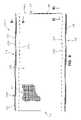
- FIG. 1is a perspective view of a patient support positioned on an exemplary hospital bed, with a portion of the patient support being cut away to show interior components of the patient support;
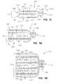
- FIG. 2is a perspective view of a patient support, with a portion being cut away to show interior components of the patient support;
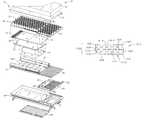
- FIG. 3is an exploded view of components of the illustrated embodiment of a patient support
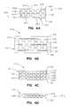
- FIGS. 4 a - 4 fillustrate side views of various configurations of a three-dimensional material
- FIG. 4 gis a side view of one embodiment of a three-dimensional spacer material
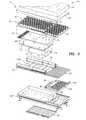
- FIG. 5illustrates another configuration of three-dimensional material including two different embodiments of three-dimensional material
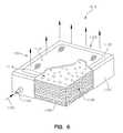
- FIG. 6illustrates a perspective view of one embodiment of a support surface including three-dimensional material and a foam base, with a portion of the cover cut away;
- FIG. 7illustrates a perspective view of a second embodiment of a support surface including three-dimensional material and a foam base, with a portion of the cover cut away;
- FIG. 8is top view of another embodiment of a support surface including layers of three-dimensional material, with a portion of the cover cut-a-way;
- FIG. 9is cross section of FIG. 8 along 9 - 9 showing the interior of the support surface
- FIG. 10is cross section of FIG. 8 along 10 - 10 showing the interior of the support surface
- FIGS. 11 a - 11 billustrate side views of various configurations of a three-dimensional material similar to those in FIG. 8 .
- the support surface of the present inventionincludes a variety of features designed to accommodate a variety of beds and frames and meet the needs of many different types of patients, including bariatric patients.
- the various aspects of the novel pressure-relief support surfaceare described in detail below.
- FIG. 1shows an embodiment of a patient support 10 in accordance with the present invention.
- Patient support 10is positioned on an exemplary bed 2 .
- Bed 2is a hospital bed including a frame 4 , a headboard 36 , a footboard 38 , and a plurality of siderails 40 .
- Frame 4 of the exemplary bed 2generally includes a deck 6 supported by a base 8 .
- Deck 6includes one or more deck sections (not shown), some or all of which may be articulating sections, i.e., pivotable with respect to base 8 .
- patient support 10is configured to be supported by deck 6 .
- Patient support 10has an associated control unit 42 , which controls inflation and deflation of certain internal components of patient support 10 , among other things.
- Control unit 42includes a user interface 44 , which enables caregivers and service providers to configure patient support 10 according to the needs of a particular patient. For example, support characteristics of patient support 10 may be adjusted according to the size, weight, position, or activity of the patient.
- User interface 44also enables patient support 10 to be adapted to different bed configurations.
- deck 6may be a flat deck or a step or recessed deck.
- a caregivermay select the appropriate deck configuration via user interface 44 .
- patient support 10has a head end 32 generally configured to support a patient's head and/or upper body region, and a foot end 34 generally configured to support a patient's feet and/or lower body region.
- Patient support 10includes a cover 12 which defines an interior region 14 .
- interior region 14includes a first layer 20 , a second layer 50 , and a third layer 52 .
- first layer 20a first layer 20
- second layer 50a second layer 50
- third layer 52a third layer 52 .
- other embodiments of the present inventionmay not include all three of these layers, or may include additional layers, without departing from the scope of the present invention.
- first layer 20includes a support material
- second layer 50includes a plurality of vertically-oriented inflatable bladders located underneath the first layer 20
- third layer 52includes a plurality of pressure sensors located underneath the vertical bladders of second layer 50 , as more particularly described below.
- interior region 14Also located within interior region 14 are a plurality of bolsters 54 , one or more filler portions 56 , and a pneumatic valve control box 58 .
- a fire-resistant material(not shown) may also be included in the interior region 14 .
- Patient support 10may be coupled to deck 6 by one or more couplers 46 .
- couplers 46are conventional woven or knit or fabric straps including a D-ring assembly or Velcro®-brand strip or similar fastener. It will be understood by those skilled in the art that other suitable couplers, such as buttons, snaps, or tethers may also be used equally as well.
- FIG. 3Components of one embodiment of a patient support in accordance with the present invention are shown in exploded view in FIG. 3 .
- This embodiment of patient support 10includes a top cover portion 16 and a bottom cover portion 18 .
- Top cover portion 16 and bottom cover portion 18couple together by conventional means (such as zipper, Velcro® strips, snaps, buttons, or other suitable fastener) to form cover 12 , which defines interior region 14 . While a plurality of layers and/or components are illustrated within interior region 14 , it will be understood by those of skill in the art that the present invention does not necessarily require all of the illustrated components.
- a first support layer 20is located below top cover portion 16 in interior region 14 .
- First support layer 20includes one or more materials, structures, or fabrics suitable for supporting a patient, such as foam, inflatable bladders, or three-dimensional material. Suitable three-dimensional materials include Spacenet, Tytex, and/or similar materials. One embodiment of a suitable three dimensional material for support layer 20 is shown in FIG. 4 , described below.
- a second support layer 50 including one or more inflatable bladder assemblies coupled to a base 96is located underneath the first support layer 20 .
- the illustrated embodiment of the second support layer 50includes first, second and third bladder assemblies, namely, a head section bladder assembly 60 , a seat section bladder assembly 62 , and a foot section bladder assembly 64 .
- first, second and third bladder assembliesnamely, a head section bladder assembly 60 , a seat section bladder assembly 62 , and a foot section bladder assembly 64 .
- the base 96is a plastic sheet.
- “Different sections of the support surfacemay have differently sized vertical air cells within them.
- the vertical air cells used in the head and back sections of the support surfacehave a larger height than those used in the foot section.
- the vertical air cells of the head and back sectionshave a height in the range of 5-8 inches and the vertical air cells of the foot section have a height in the range of 3-5 inches.
- the vertical air cells of the head and back sectionsare about 6-7 inches high and the vertical air cells of the foot section are about 4-4.5 inches high.”
- a pressure-sensing layer 69illustratively including first and second sensor pads, namely a head sensor pad 68 and a seat sensor pad 70 , is positioned underneath bladder assemblies 60 , 62 , 64 .
- Head sensor pad 68is generally aligned underneath head section bladder assembly 60
- seat sensor pad 70is generally aligned underneath seat section bladder assembly 62 , as shown.
- a single sensor pad or additional sensor padsfor example, located underneath foot section bladder assembly 64 , and/or different alignments of the sensor pads, are provided. Additional details of pressure sensing layer 69 can be found in U.S. patent application title PATIENT SUPPORT HAVING REAL TIME PRESSURE CONTROL, application Ser. No. 11/119,635, which is expressly incorporated by reference herein.
- a turn-assist cushion or turning bladder or rotational bladder 74is located below sensor pads 68 , 70 .
- the exemplary turn-assist cushion 74 shown in FIG. 3includes a pair of inflatable bladders.
- Another suitable rotational bladderis a bellows-shaped bladder.
- Another suitable turn-assist cushionis disclosed in, for example, U.S. Pat. No. 6,499,167 to Ellis, et al., which patent is owned by the assignee of the present invention and incorporated herein by this reference.
- turn-assist cushions 74are not necessarily a required element of the present invention.
- a plurality of other support components 66 , 72 , 76 , 78 , 80 , 84 , 86 , 90are also provided in the embodiment of FIG. 3 .
- One or more of these support componentsare provided to enable patient support 10 to be used in connection with a variety of different bed frames, in particular, a variety of bed frames having different deck configurations.
- One or more of these support componentsmay be selectively added to or removed from patient support 10 in order to conform patient support 10 to a particular deck configuration, such as a step or recessed deck or a flat deck.
- the support components illustrated in FIG. 3are made of foam, inflatable bladders, three-dimensional material, other suitable support material, or a combination of these.
- head filler 66includes a plurality of foam ribs extending transversely across patient support 10 .
- Filler portion 72includes a foam layer positioned substantially underneath the sensor pads 68 , 70 and extending transversely across the patient support 10 .
- Head bolster assembly 76seat bolster assembly 78 , and foot section bolster assembly 86 each include longitudinally-oriented inflatable bladders spaced apart by coupler plates 144 .
- first foot filler portion 80includes a plurality of inflatable bladders extending transversely across patient support 10
- second foot filler portion 84includes a foam member, illustratively with portions cut out to allow for retractability of the foot section or for other reasons.
- Deck filler portion 90includes a plurality of transversely-extending inflatable bladders. As illustrated, deck filler portion 90 includes two bladder sections, and is located outside of cover 12 . However, one of ordinary skill in the art will recognize that deck filler portion 90 may include one or more bladder regions, or may be located within interior region 14 , without departing from the scope of the present invention.
- a pneumatic valve box 58 and an air supply tube assembly 82are also provided in the illustrated embodiment.
- Receptacle 88is sized to house pneumatic valve box 58 .
- receptacle 88is coupled to bottom cover portion 18 by Velcro® strips.
- support layer 20includes a breathable or air permeable material which provides cushioning or support for a patient positioned thereon and allows for circulation of air underneath a patient.
- the circulated airmay be at ambient temperature, or may be cooled or warmed in order to achieve desired therapeutic effects.
- support layer 20includes or is enclosed in a low friction material (such as spandex, nylon, or similar material) enclosure that allows support layer 20 to move with movement of a patient on patient support 10 , in order to reduce shear forces or for other reasons. Additional details relating to patient support 10 are found in U.S. patent application titled PATIENT SUPPORT, U.S. patent application Ser. No. 11/120,080, which is expressly incorporated by reference herein.
- a low friction materialsuch as spandex, nylon, or similar material
- a first embodiment of the pressure-relief support surface of the present inventionincludes a cover and a plurality of layers of a three-dimensional material located within an interior region of the cover.
- the three-dimensional materialis an air permeable network of fibers that has resilient, spring-like qualities, and allows for internal air circulation, for example, to provide cooling to aid in wound healing and minimize patient perspiration.
- the circulated aircould be air that is above, at, or below ambient temperature in order to warm the patient if the patient is cool and vice versa, or achieve other desired therapeutic effects.
- the three-dimensional materialalso has low-friction characteristics; that is, it is able to move or slide along with the movement of the patient on the support surface to reduce shear forces.
- the three-dimensional materialis a collapsible, slidable or lockable material.
- the three-dimensional materialis made of a woven, knitted, or non-woven fabric which comprises thermoplastic fibers or monofilaments.
- the three-dimensional materialis a breathable monofilament polyester mesh fabric that is formed into various three-dimensional patterns after weaving such as is manufactured by Freudenberg & Co. of Weinheim, Germany.
- a three-dimensional knit materialsuch as is manufactured by Tytex Group (Tytex Inc. of Rhode Island, U.S.A.) is used in place of or in addition to the SpaceNet or other three-dimensional material.
- FIGS. 4 a - 4 fillustrate alternative embodiments of a support surface including a three-dimensional material located within an interior region of a cover.
- the illustrated three-dimensional materialgenerally includes a plurality of alternating dome- or semicircular-shaped projections and depressions, or peaks and troughs.
- peaks and troughsmay be mentioned in connection with particular embodiments discussed below, but it is understood that these dimensions are not so limited. Any type of three dimensional material, with peaks and troughs of any size may be used. In certain embodiments, these dimensions are adjusted to, for example, achieve particular support characteristics.
- FIG. 4 ais a side view of a first embodiment of a support surface 1010 including the three-dimensional material located inside a cover 1012 .
- the cover 1012defines an interior region 1014 , which contains a plurality of layers of three-dimensional material 1020 .
- Each individual layer of three-dimensional materialincludes a plurality of peaks or substantially dome-shaped projections 1022 and troughs or depressions 1024 .
- FIG. 4 athere are two layers 1028 , 1030 of three-dimensional material stacked “back-to-back”, with the dome-shaped projections or peaks facing in opposite directions, located above a separator material 1026 , and two layers 1032 , 1034 of the three-dimensional material stacked or positioned back-to-back below the separator material 1026 .
- the dome-shaped projections or peaks 1022 and depressions or troughs 1024 , respectively,are substantially aligned.
- the separator material 1026is comprised of the same material used for the cover 1012 , or another suitable divider material. In the illustrated embodiments, the separator material 1026 is breathable or air permeable. Alternatively or in addition, the separator material 1026 provides support for the layers 1028 , 1030 . In alternative embodiments, no separator material 1026 is used.
- the cover 1012has a top surface 1016 and a bottom surface 1018 .
- a first sublayer 1028 of the three-dimensional materialhas dome-shaped projections 1022 projecting upwardly and located adjacent the top surface 1016 of the cover within the interior region 1014 .
- a second sublayer 1030 of the three-dimensional materialhas dome-shaped projections 1022 facing downwardly and located adjacent the separator material 1026 .
- a third sublayer 1032 of the three-dimensional materialhas dome-shaped projections 1022 facing upwardly toward and adjacent to the separator material 1026 .
- a fourth sublayer 1034 of the three-dimensional materialhas dome-shaped projections 1022 projecting downwardly toward the bottom surface 1018 of the cover 1012 .
- FIG. 4 billustrates an alternative embodiment of the support surface 1010 , which is similar to the embodiment shown in FIG. 4 a , except that within the interior region 1014 of the cover 1012 , there is located three layers of a three-dimensional spacer material 1036 , 1038 , 1040 .
- the first layer of spacer material 1036is located above the first sublayer 1028 of three-dimensional fabric.
- the second layer 1038 of three-dimensional spacer materialis located between the second and third sublayers 1030 , 1032 of three-dimensional material.
- the third layer 1040 of three-dimensional spacer fabricis located below or underneath the fourth sublayer 1034 of three-dimensional material.
- the layers of three-dimensional spacer material 1036 , 1038 , 1040are made of an air permeable spacer fabric 1041 .
- the three-dimensional spacer fabricis a lightweight material that also has a cushioning effect and is breathable and able to transfer moisture.
- the spacer fabricis a three-dimensional knit spacer fabric manufactured by Tytex Group.
- the three-dimensional spacer fabricis latex-free.
- FIG. 4 gis a side view of one form of spacer fabric 1041 .
- FIG. 4 cshows another alternative embodiment of the support surface 1010 , which is similar to the embodiment shown in FIG. 4 a , except that it includes a second layer of a separator material 1042 and two additional individual layers 1052 , 1054 of the three-dimensional material.
- first and second sublayers 1044 , 1046 of the three-dimensional materialare located above the first separator material 1026 .
- Second and third sublayers 1048 , 1050 of the three-dimensional materialare located between the first separator material 1026 and the second separator material 1042 .
- the third and fourth individual layers 1052 , 1054 of three-dimensional materialare located between the second separator material 1042 and the bottom surface 1018 of the cover 1012 .
- the layers of separator material 1026 , 1042are comprised of the same material as is used for the cover 1012 , a three-dimensional spacer fabric as described above, or other similar suitable material.
- FIG. 4 dshows yet another alternative embodiment of the support surface 1010 .
- a first individual layer 1056 of three-dimensional materialis separated by a separator material 1026 from a second individual layer 1058 of three-dimensional material, within the cover 1012 , so that there is only one individual layer of three-dimensional material on either side of the separator material 1026 .
- the peaks or dome-shaped projections and troughs or depressions of the layers 1056 and 1058are substantially aligned as discussed above.
- FIG. 4 eshows a side view of two back-to-back individual layers of three dimensional material 1060 , 1062 which are positioned so that the peaks or dome-shaped projections 1066 and troughs or depressions 1068 are aligned directly above or below each other.
- the material located between the peaks and depressions 1066 , 1068 of the layers 1060 , 1062is welded together at points 1064 . Welding, joining, or otherwise fastening the material together at points 1064 maintains the back-to-back alignment of the peaks and depressions 1066 , 1068 . It is understood that in any of the illustrated embodiments, the material may be welded as shown in FIG. 4 e.
- FIG. 4 fshows still another embodiment of the three-dimensional material located within the cover 1012 of the support surface 1010 .
- Located between the second and third layers 1074 , 1078 of spacer fabricis a pair of individual layers 1076 of three-dimensional material aligned back-to-back as discussed above.
- each sublayer 1072 , 1076 , 1080is another layer 1080 comprised of two back-to-back layers of three-dimensional material.
- the individual layers of three-dimensional material that make up each sublayer 1072 , 1076 , 1080are held together by welding, plastic ties or other suitable fasteners.
- the height of the projections and depressions of the three-dimensional material illustrated in FIGS. 4 a - 4 fis about 3.1 mm.
- the height of three-dimensional spacer fabric 1041 illustrated in FIG. 4 gis about 0.2 inches.
- the total height from the top of the upper projection to the bottom of the lower projectionequals about 0.44 inches.
- the three-dimensional material and spacer fabrichave different dimensions and thus the layers or combination of layers have different heights.
- FIG. 5shows yet another embodiment of the three-dimensional material located within the cover 1012 of the support surface 1010 .
- the layers 1092 , 1094 , 1096have smaller projections and depressions than the layers 1084 , 1086 , 1088 , 1090 .
- the projections and depressions of layers 1092 , 1094 , 1096each have a diameter and/or height that is smaller than the diameter and/or height of the projections and depressions of layers 1084 , 1086 , 1088 , 1090 .
- All of the layers 1084 , 1086 , 1088 , 1090 , 1092 , 1094 , 1096include two individual layers of three-dimensional material positioned back-to-back, however, the projections and depressions of layers 1092 , 1094 , 1096 are not substantially aligned as they are in the layers 1084 , 1086 , 1088 , 1090 .
- a spacer fabricis provided in between one or more of the layers or sublayers. It is understood that, in alternative embodiments of the support surface 1010 , there are varying numbers of layers and/or sublayers of three-dimensional material and spacer fabric. For example, in general, the number of layers or sublayers is between 1 and 20. In one embodiment the number of layers is 1012 .
- the cover 1012which defines the interior region within which the three-dimensional material is positioned to form a support surface, is made of a stretchy, breathable material such as Lycra®. It is understood that any of the illustrated embodiments of FIGS. 4 a - 4 f may be inserted into the interior region 1014 of the cover 1012 to form the support surface 1010 .
- any of the configurations shown in FIG. 4 a - 4 fconstitute one layer and multiple such layers are inserted within the interior region 1014 of the cover 1012 .
- the support surface 1010constitutes one layer, for example, as a “topper” or coverlet, positioned above, below, or in between one or more other layers of patient support 10 .
- additional layers of one or more other support materials, such as foam and/or air bladders,are also included within the interior region of the cover.
- the support surface 1010includes a three-dimensional material and a foam base.
- a cover 1100includes a top surface 1102 and an air inlet 1104 . At least a portion 1107 of the top surface 1102 is air permeable and permits air flow in the direction of arrows 1103 .
- the air inlet 1104is coupled to an air supply (not shown) so that air flows in the direction of arrow 1105 into the interior region 1110 of the cover 1100 through the air inlet 1104 . Because at least a portion 1107 of the top surface 1102 permits air flow, the air that flows into the interior region 1110 flows through the interior region 1110 and then upwardly out through the top surface 1102 .
- the air circulated through the support surfaceis generally at ambient temperature. It is within the scope of the invention that various temperatures of air above and below the ambient temperature could be circulated. In alternative embodiments, the air is heated or cooled prior to circulation. In such embodiments, the air temperature is controlled by the patient or caregiver, or is automatically controlled in response to a measurement of the patient's temperature or surface temperature of the patient support. In still other embodiments, top surface 1102 is vapor and moisture permeable but air impermeable. The air does not exit top surface 1102 but exits through an opening or slit (not shown) in a head end 1103 of support surface 1010 . In yet another embodiment, fluid is circulated through the support surface. The fluid could include water, refrigerant, gel, or any other suitable fluid for heating and cooling a patient.
- a plurality of layers of three-dimensional material 1106 and a foam base 1108are located in the interior region 1110 of the cover 1100 .
- the plurality of layers of three-dimensional material 1106may be configured in any of the ways shown in FIGS. 4 a - 4 f , 5 , and 9 - 11 b .
- the three-dimensional material 1106is of the type commonly known as Spacenet. However, it is understood that other suitable three-dimensional networked fiber materials may be used.
- the foam base 1108is positioned underneath the plurality of layers of three-dimensional material 1106 within the interior region 1110 of the cover 1100 .
- the base 1108is constructed of reticulated foam.
- the foam base 1108has a thickness of about 1 inch. However, it is understood that other suitable thicknesses and types of foam may be used. In alternative embodiments, foam base 1108 is not included within cover 1100 or not used at all.
- the embodiment of the support surface 1010 shown in FIG. 6is thought to be particularly useful to support the area underneath a patient's heels while that patient is lying on a hospital bed, for example.
- the air flow through the top surface 1102provides a cooling effect, and the resilient qualities of the three-dimensional material 1106 are configured to reduce the interface pressure between the patient's heels and the top surface 1102 of the cover 1100 .
- the embodiment of the support surface 1110 that is shown in FIG. 7is similar to the embodiment of FIG. 6 except that the stack of three-dimensional layers 1106 within the interior region 1110 is divided into a plurality of columns or log-shaped cells 1116 .
- the columns 1116are separated by channels 1118 which additionally allow air flow between the columns 1116 of three-dimensional material upwardly through the top surface 1120 of the cover 1112 .
- a top surface 1120 of the cover 1112includes a plurality of pleats, valleys, indentations, or creases 1114 which generally correspond to the location of the channels 1118 within the interior region 1110 .
- the top surface 1120 of the cover 1112also includes a plurality of apertures 1122 which allow for air flow through the top surface 1120 .
- the columns 1116 of the three-dimensional material 1106allow the three-dimensional material to move more freely in response to movement of a patient positioned on the support surface.
- Each individual column 1116is movable independently of the others.
- the rate of flow of the air into the interior region 1110 of the cover 1112 through the inlet 1104can be adjusted in order to remove moisture from the interior region 1110 or from the top surface 1120 and have a drying effect on the skin of a patient or portion of a patient's body that is adjacent to the top surface 1120 .
- the rate of air flow through the inlet 1104is adjustable. For example, it can be increased to partially or fully inflate the interior region 1110 to make the top surface 1120 firmer as may be desired, for example, for ease of transfer of the support surface or to support the patient's weight.
- Still other embodiments of the support surface 1110include a layer of three-dimensional material in combination with one or more inflatable cushions or bladders.
- FIGS. 8-10show yet another embodiment of support surface 1100 .
- Support surface 1010includes a cover 1300 and a plurality of layers of three dimensional material 1302 .
- Cover 1300defines an interior region 1304 , which contains the plurality of layers of three-dimensional material 1302 .
- Each individual layer of three-dimensional materialincludes a plurality of peaks or substantially dome-shaped projections 1310 and troughs or depressions 1312 .
- Cover 1300includes a first longitudinal side 1314 , a second longitudinal side 1316 , a head end 1315 , a foot end 1317 , an upper cover 1318 , and a lower cover 1320 .
- a loop fastener 1322is provided allow first and second longitudinal sides 1314 , 1316 . Loop faster 1322 matches to a hook fastener (not shown) located on an interior surface of a patient support cover (not shown). The hook fastener and loop fastener 1322 hold cover 1300 in place within the patient support cover.
- FIG. 9A cutaway along longitudinal side 1314 is illustrated in FIG. 9 .
- the dome-shaped projections or peaks 1310 and depressions or troughs 1312 , respectively,are substantially aligned.
- upper cover 1318 and lower cover 1320extend beyond the two layers 1306 , 1308 .
- Upper cover 1318 and lower cover 1320are stitched with a convention stitch at a first stitch location 1324 , a second stitch location 1326 , a third stitch location 1328 , and a forth stitch location 1330 .
- First stitch locationis near layers 1306 , 1308 and used to hold layers 1306 , 1307 within cover 1300 .
- Second stitch location 1326is provided to reinforce first stitch location 1324 .
- Upper and lower covers 1318 , 1320define a folded region 1331 near an end 1332 of upper cover 1318 and lower cover 1320 . Stitching through folded region 1331 occurs at third and fourth stitch locations 1328 , 1330 .
- a hem 1334covers the entire folded region 1331 .
- Hoop fastener 1322is held in place by hem 1334 .
- upper cover 1318 and lower cover 1320are RF Welded at the stitch and hem locations.
- FIG. 10A cutaway along foot end 1317 is illustrated in FIG. 10 .
- Upper and lower covers 1318 , 1320define a folded region 1340 near an end 1342 of upper and lower covers 1318 , 1320 .
- Stitching through folded region 1340occurs at fifth stitch location 1344 .
- a stitch or hemgoes through folded region 1340 .
- Folded region 1340includes a portion of layers 1306 , 1308 and a portion of upper and lower covers 1318 , 1320 .
- FIGS. 11A and 11Bshow alternative embodiments of support surface 1010 that are similar to those in FIGS. 8-10 .
- FIG. 11Ashows four individual layers or strips 1350 , 1352 , 1354 , 1356 of the three-dimensional material provided within the interior region 1304 of the cover 1300 .
- FIG. 11Bshows eight individual layers or strips 1358 , 1360 , 1362 , 1364 , 1366 , 1368 , 1370 , 1372 of the three-dimensional material provided within the interior region 1304 of the cover 1300 .
- any number of layers of three-dimensional materialmay be used. Layers of different thickness and support characteristics could also be used.
- a layer of material similar to that of the covercould be provide between each layer of three-dimensional material or between groups of layers of three-dimensional material.
- the three-dimensional material used in certain embodiments of the support surface 1010is generally enclosed in a cover.
- an outer cover or tickingis used to enclose all of the internal layers of the support surface within an interior region.
- the outer covering or tickingmay be provided in addition to or in place of the cover surrounding the three-dimensional material, described above.
- a zipper or other suitable fasteneris provided to couple two halves of the outer cover together around the support surface layers.
- the outer cover or tickingis made of a moisture resistant material, such as plastic or a plastic-coated material.
- a urethane-coated fabricis used.
- all or a portion of the outer tickingis made of a low air loss plastic or plastic-coated material, or is otherwise breathable.
- the outer tickingmay be coated with a low friction material such as Teflon® to reduce sheer between the patient and the support surface.
- the outer ticking or portions thereofmay be treated with chemicals, ozone or ions so that it is bacteria resistant. Further, all or portions of the outer ticking surface may be treated or otherwise designed to resist staining, for example, using a patterned tick.
- the outer tickingis generally designed to prevent fluid ingress through the use of sealed ticking or wicking channels. Also, in certain embodiments the outer ticking is designed to be disposable or replaceable.
- the outer cover or tickingis made of a moisture and vapor permeable but air impermeable layer. These materials are typically covered with either a Teflon® coating or a Urethane coating.
- outer tickingare designed primarily to minimize the amount of maintenance required to properly care for and maintain the condition of the outer ticking and the support layers within.
- the outer tickingis also configured to improve the user friendliness of the support surface 1010 .
- instructions for the caregiver with regard to appropriate installation and use of the support surface 1010are applied to the top surface or other plainly visible areas of the outer ticking.
- indications, icons, symbols, or distinct color coding schemesmay be used to guide the caregiver through proper installation and use. Alignment decals and/or an outline of the proper orientation of a patient on the surface are also provided in certain embodiments.
Landscapes
- Health & Medical Sciences (AREA)
- Nursing (AREA)
- Life Sciences & Earth Sciences (AREA)
- Animal Behavior & Ethology (AREA)
- General Health & Medical Sciences (AREA)
- Public Health (AREA)
- Veterinary Medicine (AREA)
- Invalid Beds And Related Equipment (AREA)
Abstract
Description
Claims (18)
Priority Applications (2)
| Application Number | Priority Date | Filing Date | Title |
|---|---|---|---|
| US12/343,613US7937791B2 (en) | 2004-04-30 | 2008-12-24 | Pressure relief surface |
| US13/103,360US8196240B2 (en) | 2004-04-30 | 2011-05-09 | Pressure relief surface |
Applications Claiming Priority (8)
| Application Number | Priority Date | Filing Date | Title |
|---|---|---|---|
| US56721504P | 2004-04-30 | 2004-04-30 | |
| US60801304P | 2004-09-08 | 2004-09-08 | |
| US63625204P | 2004-12-15 | 2004-12-15 | |
| US66514105P | 2005-03-25 | 2005-03-25 | |
| US66524105P | 2005-03-25 | 2005-03-25 | |
| US11998005A | 2005-05-02 | 2005-05-02 | |
| US11/324,447US7469436B2 (en) | 2004-04-30 | 2006-01-03 | Pressure relief surface |
| US12/343,613US7937791B2 (en) | 2004-04-30 | 2008-12-24 | Pressure relief surface |
Related Parent Applications (1)
| Application Number | Title | Priority Date | Filing Date |
|---|---|---|---|
| US11/324,447ContinuationUS7469436B2 (en) | 2004-04-30 | 2006-01-03 | Pressure relief surface |
Related Child Applications (1)
| Application Number | Title | Priority Date | Filing Date |
|---|---|---|---|
| US13/103,360ContinuationUS8196240B2 (en) | 2004-04-30 | 2011-05-09 | Pressure relief surface |
Publications (2)
| Publication Number | Publication Date |
|---|---|
| US20090119846A1 US20090119846A1 (en) | 2009-05-14 |
| US7937791B2true US7937791B2 (en) | 2011-05-10 |
Family
ID=36566042
Family Applications (3)
| Application Number | Title | Priority Date | Filing Date |
|---|---|---|---|
| US11/324,447Expired - LifetimeUS7469436B2 (en) | 2004-04-30 | 2006-01-03 | Pressure relief surface |
| US12/343,613Expired - LifetimeUS7937791B2 (en) | 2004-04-30 | 2008-12-24 | Pressure relief surface |
| US13/103,360Expired - Fee RelatedUS8196240B2 (en) | 2004-04-30 | 2011-05-09 | Pressure relief surface |
Family Applications Before (1)
| Application Number | Title | Priority Date | Filing Date |
|---|---|---|---|
| US11/324,447Expired - LifetimeUS7469436B2 (en) | 2004-04-30 | 2006-01-03 | Pressure relief surface |
Family Applications After (1)
| Application Number | Title | Priority Date | Filing Date |
|---|---|---|---|
| US13/103,360Expired - Fee RelatedUS8196240B2 (en) | 2004-04-30 | 2011-05-09 | Pressure relief surface |
Country Status (1)
| Country | Link |
|---|---|
| US (3) | US7469436B2 (en) |
Cited By (30)
| Publication number | Priority date | Publication date | Assignee | Title |
|---|---|---|---|---|
| US20100122417A1 (en)* | 2008-11-19 | 2010-05-20 | Kci Licensing, Inc. | Multi-Layered Support System |
| US20110047710A1 (en)* | 2008-03-11 | 2011-03-03 | Allyn Beard | Mattress |
| US20110209289A1 (en)* | 2004-04-30 | 2011-09-01 | Meyer Eric R | Pressure relief surface |
| US20110219548A1 (en)* | 2006-05-11 | 2011-09-15 | Kci Licensing, Inc. | Multi-Layered Support System |
| US20110247143A1 (en)* | 2008-04-15 | 2011-10-13 | Richards Sandy M | Temperature and moisture regulating topper for non-powered person-support surfaces |
| US20110289685A1 (en)* | 1998-05-06 | 2011-12-01 | Romano James J | Cover system for a patient support surface |
| US20120284926A1 (en)* | 2011-05-12 | 2012-11-15 | Tyree Steven | Low shear mattress topper constructions |
| US8397326B2 (en) | 2010-02-05 | 2013-03-19 | Stryker Corporation | Patient/invalid handling support |
| US8595873B2 (en) | 2010-12-08 | 2013-12-03 | Hill-Rom Services, Inc. | Mattress deflation management |
| US8918930B2 (en) | 2011-01-04 | 2014-12-30 | Huntleigh Technology Limited | Methods and apparatuses for low-air-loss (LAL) coverlets and airflow units for coverlets |
| US9254231B2 (en) | 2011-07-28 | 2016-02-09 | Huntleigh Technology Limited | Multi-layered support system |
| US9326903B2 (en) | 2011-10-03 | 2016-05-03 | Huntleigh Technology Limited | Multi-layered support system |
| US9433300B2 (en) | 2013-02-28 | 2016-09-06 | Hill-Rom Services, Inc. | Topper for a patient surface |
| US9462893B2 (en) | 1998-05-06 | 2016-10-11 | Hill-Rom Services, Inc. | Cover system for a patient support surface |
| US9504620B2 (en) | 2014-07-23 | 2016-11-29 | American Sterilizer Company | Method of controlling a pressurized mattress system for a support structure |
| US9782312B2 (en) | 2013-09-05 | 2017-10-10 | Stryker Corporation | Patient support |
| US9820904B2 (en) | 2011-07-13 | 2017-11-21 | Stryker Corporation | Patient/invalid handling support |
| US9875633B2 (en) | 2014-09-11 | 2018-01-23 | Hill-Rom Sas | Patient support apparatus |
| US10045715B2 (en) | 2015-04-27 | 2018-08-14 | Hill-Rom Services, Inc. | Self-compensating bed scale system for removable components |
| US10054479B2 (en) | 2015-05-05 | 2018-08-21 | Hill-Rom Services, Inc. | Bed with automatic weight offset detection and modification |
| US10238566B2 (en) | 2010-12-08 | 2019-03-26 | Hill-Rom Services, Inc. | Mattress bladder boosting during chair egress |
| US20200253388A1 (en)* | 2012-02-21 | 2020-08-13 | Hill-Rom Services, Inc. | Topper with targeted fluid flow distribution |
| US10765227B2 (en)* | 2017-04-21 | 2020-09-08 | Me. Res. S.R.L. | Mattress |
| US11357683B2 (en) | 2005-07-08 | 2022-06-14 | Hill-Rom Services, Inc. | Foot zone of a mattress |
| US20220346562A1 (en)* | 2021-04-29 | 2022-11-03 | Zachariah Clarence Holtquist | Mattress |
| US12042440B1 (en) | 2021-04-16 | 2024-07-23 | Turn Medical, LLC | Stowable patient supports |
| US12121479B1 (en) | 2021-04-16 | 2024-10-22 | Turn Medical, LLC | Strap and release system |
| WO2024164029A3 (en)* | 2023-02-02 | 2024-10-24 | Universal Tech Corporation | Decubitus prevention device |
| US12226356B1 (en) | 2021-04-16 | 2025-02-18 | Turn Medical, LLC | Adjustable posterior head support |
| US12403057B1 (en) | 2021-04-16 | 2025-09-02 | Turn Medical, LLC | Proning face pack |
Families Citing this family (65)
| Publication number | Priority date | Publication date | Assignee | Title |
|---|---|---|---|---|
| US7469437B2 (en) | 2005-06-24 | 2008-12-30 | Tempur-Pedic Management, Inc. | Reticulated material body support and method |
| EP2902586A1 (en) | 2006-05-09 | 2015-08-05 | Hill-Rom Services, Inc. | Pulmonary mattress |
| US20080040860A1 (en)* | 2006-08-17 | 2008-02-21 | Gaymar Industries, Inc. | Turn-assist with access areas |
| EP2702966B1 (en)* | 2008-04-15 | 2019-07-17 | Hill-Rom Services, Inc. | Microclimate management system |
| US8296887B2 (en)* | 2008-09-22 | 2012-10-30 | Stryker Corporation | Resilient material/air bladder system |
| WO2010078047A2 (en)* | 2008-12-17 | 2010-07-08 | Stryker Corporation | Patient support |
| FR2949320B1 (en) | 2009-08-31 | 2012-11-16 | Hill Rom Ind Sa | LATERAL TILT DEVICE |
| US8677536B2 (en)* | 2009-11-18 | 2014-03-25 | Hill-Rom Services, Inc. | Method and apparatus for sensing foot retraction in a mattress replacement system |
| US9420895B2 (en)* | 2009-12-17 | 2016-08-23 | Stryker Corporation | Patient support |
| US20110185508A1 (en)* | 2010-02-02 | 2011-08-04 | Charles Hsu | Prevention and Treatment of Pressure Sores Using a Sheet with an Integrated Inflatable Component |
| US8266742B2 (en) | 2010-12-06 | 2012-09-18 | Hill-Rom Services, Inc. | Biometric bed configuration |
| USD690424S1 (en) | 2011-01-26 | 2013-09-24 | Sage Products, Inc. | Set of components for a patient repositioning system |
| US9295600B2 (en) | 2011-04-08 | 2016-03-29 | Hill-Rom Services, Inc. | Person support apparatus with activity and mobility sensing |
| US20120259245A1 (en) | 2011-04-08 | 2012-10-11 | Receveur Timothy J | Person support apparatus with activity and mobility sensing |
| US9700247B2 (en) | 2012-03-21 | 2017-07-11 | Hill-Rom Services, Inc. | Patient support apparatus with redundant identity verification |
| CN102631097B (en)* | 2012-04-17 | 2015-06-03 | 东莞市慕思寝室用品有限公司 | Three-dimensional modified polyester fiber mattress |
| US9009892B2 (en) | 2012-05-10 | 2015-04-21 | Hill-Rom Services, Inc. | Occupant support and topper assembly with liquid removal and microclimate control capabilities |
| US20130340175A1 (en)* | 2012-06-20 | 2013-12-26 | International Business Machines Corporation | Managing mattress pressure on wounds |
| US9833369B2 (en) | 2012-06-21 | 2017-12-05 | Hill-Rom Services, Inc. | Patient support systems and methods of use |
| US9228885B2 (en)* | 2012-06-21 | 2016-01-05 | Hill-Rom Services, Inc. | Patient support systems and methods of use |
| JP6017686B2 (en) | 2012-06-21 | 2016-11-02 | ヒル−ロム サービシズ,インコーポレイテッド | Patient holding system and method of use |
| US9358168B2 (en) | 2012-09-04 | 2016-06-07 | Hill-Rom Services, Inc. | Patient position detection for patient support surface |
| US9468307B2 (en) | 2012-09-05 | 2016-10-18 | Stryker Corporation | Inflatable mattress and control methods |
| WO2014039661A1 (en)* | 2012-09-05 | 2014-03-13 | Stryker Corporation | Patient support |
| US20150335506A9 (en)* | 2012-09-10 | 2015-11-26 | Boyd Thomas Kildey | Sleep Cycle Bed |
| ES2687959T3 (en)* | 2012-10-18 | 2018-10-30 | Tempur-Pedic Management, Llc | Support cushion |
| US9463124B2 (en)* | 2013-01-15 | 2016-10-11 | Hill-Rom Services, Inc. | Microclimate system for a patient support apparatus |
| US10238560B2 (en)* | 2013-03-13 | 2019-03-26 | Hill-Rom Services, Inc. | Air fluidized therapy bed having pulmonary therapy |
| US9005101B1 (en) | 2014-01-04 | 2015-04-14 | Julian Van Erlach | Smart surface biological sensor and therapy administration |
| US9615984B2 (en) | 2014-03-11 | 2017-04-11 | Herniamesh S.R.L. | Treatment of chronic back pain using a three-dimensional monofilament mattress overlay |
| US9849734B2 (en) | 2014-10-31 | 2017-12-26 | The Goodyear Tire & Rubber Company | Pneumatic tire with a three dimensional component |
| US20160235610A1 (en) | 2015-02-18 | 2016-08-18 | Allen Medical Systems, Inc. | Using patient monitoring data to control a person support apparatus |
| WO2017008080A1 (en)* | 2015-07-09 | 2017-01-12 | Skydex Technologies, Inc. | Pressure distributing aligned arrays of cushioning void cells |
| US9514841B1 (en) | 2015-11-23 | 2016-12-06 | International Business Machines Corporation | Implementing eFuse visual security of stored data using EDRAM |
| US10071603B2 (en) | 2016-04-26 | 2018-09-11 | The Goodyear Tire & Rubber Company | Lightweight tire |
| CN207784763U (en) | 2017-06-22 | 2018-08-31 | 明达实业(厦门)有限公司 | A kind of Aerated bed structure |
| JP6869925B2 (en)* | 2017-07-27 | 2021-05-12 | ヒル−ロム サービシズ,インコーポレイテッド | Dynamic foam mattress suitable for use in hospital beds of varying length |
| US11033117B2 (en)* | 2017-07-27 | 2021-06-15 | Hill-Rom Services, Inc. | Dynamic foam mattress adapted for use with a variable length hospital bed |
| WO2019036329A1 (en) | 2017-08-16 | 2019-02-21 | Covidien Lp | Operating table for robotic surgical systems |
| TWD191649S (en)* | 2017-11-13 | 2018-07-11 | 雃博股份有限公司 | Part of the operator panel |
| TWD191003S (en)* | 2017-11-13 | 2018-06-11 | 雃博股份有限公司 | Part of the air bed host (1) |
| US11173085B2 (en) | 2017-12-28 | 2021-11-16 | Stryker Corporation | Mattress cover for a mattress providing rotation therapy to a patient |
| US11246775B2 (en) | 2017-12-28 | 2022-02-15 | Stryker Corporation | Patient turning device for a patient support apparatus |
| US11160706B1 (en)* | 2018-04-08 | 2021-11-02 | John Keesaer | Patient support arrangement |
| US10463526B1 (en) | 2018-05-07 | 2019-11-05 | Levy Zur | Programmable pressure management support surface |
| USD877915S1 (en) | 2018-09-28 | 2020-03-10 | Stryker Corporation | Crib assembly |
| USD888964S1 (en) | 2018-09-28 | 2020-06-30 | Stryker Corporation | Crib assembly for a patient support |
| USD888962S1 (en) | 2018-09-28 | 2020-06-30 | Stryker Corporation | Cover assembly for a patient support |
| USD879966S1 (en) | 2018-09-28 | 2020-03-31 | Stryker Corporation | Crib assembly |
| USD901940S1 (en) | 2018-09-28 | 2020-11-17 | Stryker Corporation | Patient support |
| USD888963S1 (en) | 2018-09-28 | 2020-06-30 | Stryker Corporation | Cover assembly for a patient support |
| USD977109S1 (en) | 2018-09-28 | 2023-01-31 | Stryker Corporation | Crib assembly for a patient support |
| USD894226S1 (en) | 2018-10-31 | 2020-08-25 | Stryker Corporation | Display screen or portion thereof with graphical user interface |
| USD893543S1 (en) | 2018-10-31 | 2020-08-18 | Stryker Corporation | Display screen with graphical user interface |
| USD890914S1 (en) | 2018-10-31 | 2020-07-21 | Stryker Corporation | Pump |
| USD894956S1 (en) | 2018-10-31 | 2020-09-01 | Stryker Corporation | Display screen or portion thereof with graphical user interface |
| USD892159S1 (en) | 2018-10-31 | 2020-08-04 | Stryker Corporation | Display screen with animated graphical user interface |
| USD894223S1 (en) | 2018-10-31 | 2020-08-25 | Stryker Corporation | Display screen with animated graphical user interface |
| USD894957S1 (en) | 2018-10-31 | 2020-09-01 | Stryker Corporation | Display screen or portion thereof with graphical user interface |
| US12042453B2 (en) | 2019-02-26 | 2024-07-23 | Hill-Rom Services, Inc. | Patient positioning apparatus and mattress |
| US11383118B1 (en)* | 2019-05-02 | 2022-07-12 | Bryan Hines James | Inflatable impact attenuation device with discrete elements |
| WO2020232161A1 (en) | 2019-05-14 | 2020-11-19 | Ige, Llc | Support system including layers of spacer fabric and non-viscoelastic pressure relief material, and method for measuring pressure and pressure distribution properties of a support system |
| US11660242B2 (en) | 2019-06-17 | 2023-05-30 | Morgan Leigh Miller | Portable patient turning device |
| US12251346B2 (en) | 2020-04-21 | 2025-03-18 | TurnCare, Inc. | Network-enabled systems for mitigating pressure applied to a living body by an underlying surface |
| AU2023369682A1 (en)* | 2022-10-28 | 2025-06-05 | Umano Medical Inc. | Patient support having an inflatable bladder |
Citations (178)
| Publication number | Priority date | Publication date | Assignee | Title |
|---|---|---|---|---|
| US779576A (en) | 1903-09-11 | 1905-01-10 | Benjamin F Berryman | Mattress. |
| US800967A (en) | 1904-10-20 | 1905-10-03 | George S Tolman | Pneumatic mattress, &c. |
| US1121277A (en) | 1913-12-04 | 1914-12-15 | Theresa C Mitchell | Warming appliance for beds. |
| US1332933A (en) | 1916-05-12 | 1920-03-09 | Rubber Regenerating Co | Pneumatic cushion |
| GB159299A (en) | 1919-11-22 | 1921-02-22 | Charles Reginald Stone | Air- and water-mattresses and the like |
| US1772310A (en) | 1926-12-16 | 1930-08-05 | Julian D Hart | Variable-pressure bed or mattress |
| US1841410A (en)* | 1929-05-31 | 1932-01-19 | Charles D Karr | Pad holder |
| US2434641A (en)* | 1946-02-20 | 1948-01-20 | Henry L Burns | Resilient seat cushion |
| US3303518A (en) | 1962-03-05 | 1967-02-14 | Ingram George | Inflatable mattresses, pillows and cushions |
| US3492988A (en) | 1967-09-01 | 1970-02-03 | Baltzar Leo De Mare | Pneumatic positioner |
| US3574873A (en) | 1968-05-14 | 1971-04-13 | James D Weinstein | Fluid-type support structure for simulating flotation-type support |
| US3605145A (en) | 1968-12-05 | 1971-09-20 | Robert H Graebe | Body support |
| US3772717A (en) | 1971-02-05 | 1973-11-20 | Y Yuen | Inflatable mattresses and cushions |
| US3978530A (en) | 1975-11-21 | 1976-09-07 | Amarantos John G | Air inflatable bed-like device with adjustable back support |
| US4114620A (en) | 1977-03-02 | 1978-09-19 | Moore-Perk Corporation | Patient treatment pad for hot or cold use |
| US4316298A (en)* | 1980-03-12 | 1982-02-23 | Thonet Industries, Inc. | Composite mattress system |
| US4347633A (en) | 1980-07-22 | 1982-09-07 | American Hospital Supply Corporation | Patient treating mattress |
| US4448228A (en) | 1981-01-09 | 1984-05-15 | Aisin Seiki Kabushiki Kaisha | Air bag system having a branched joint |
| US4454615A (en)* | 1982-05-03 | 1984-06-19 | Medisearch Pr, Inc. | Air pad with integral securement straps |
| US4477935A (en) | 1982-01-08 | 1984-10-23 | Griffin Gordon D | Mattress support system |
| US4483029A (en) | 1981-08-10 | 1984-11-20 | Support Systems International, Inc. | Fluidized supporting apparatus |
| US4525409A (en)* | 1983-09-19 | 1985-06-25 | Flexi-Mat Corporation | Nylon or polyester treated fabric for bedding |
| US4525885A (en) | 1980-02-26 | 1985-07-02 | Mediscus Products Limited | Support appliance for mounting on a standard hospital bed |
| US4527298A (en) | 1982-03-18 | 1985-07-09 | Moulton Lee A | Electro pneumatic bed |
| US4541136A (en)* | 1983-09-01 | 1985-09-17 | Graebe Robert H | Multicell cushion |
| US4541135A (en) | 1984-04-16 | 1985-09-17 | Victor Karpov | Air mattress |
| US4542547A (en) | 1982-12-15 | 1985-09-24 | Hiroshi Muroi | Pnuematic mat with sensing means |
| US4637083A (en) | 1985-03-13 | 1987-01-20 | Support Systems International, Inc. | Fluidized patient support apparatus |
| US4638519A (en) | 1985-04-04 | 1987-01-27 | Air Plus, Inc. | Fluidized hospital bed |
| US4689844A (en) | 1984-12-18 | 1987-09-01 | Alivizatos Margaret A | Convertible body supporting pads |
| US4694521A (en) | 1985-06-19 | 1987-09-22 | Fuji Electric Co., Ltd | Human body supporting device |
| US4698864A (en)* | 1985-11-25 | 1987-10-13 | Graebe Robert H | Cellular cushion |
| US4706313A (en) | 1986-05-01 | 1987-11-17 | Comfortex, Inc. | Decubitus ulcer mattress |
| FR2596950B1 (en) | 1986-04-11 | 1988-11-18 | Huneau Jacques | MONITORING DEVICE FOR MONITORING MOBILE DISCRETE ELEMENTS, MONITORING SYSTEM COMPRISING SUCH DEVICES AND THEIR USE IN STABLE MANAGEMENT |
| US4797962A (en) | 1986-11-05 | 1989-01-17 | Air Plus, Inc. | Closed loop feedback air supply for air support beds |
| US4825486A (en) | 1987-06-05 | 1989-05-02 | Matsushita Electric Works, Ltd. | Bedsore-preventing air mattress controller |
| US4839512A (en) | 1987-01-27 | 1989-06-13 | Tactilitics, Inc. | Tactile sensing method and apparatus having grids as a means to detect a physical parameter |
| US4837877A (en) | 1987-01-20 | 1989-06-13 | Sanwa Shutter Corporation | Elevation bed |
| US4852195A (en)* | 1987-10-16 | 1989-08-01 | Schulman David A | Fluid pressurized cushion |
| US4864671A (en)* | 1988-03-28 | 1989-09-12 | Decubitus, Inc. | Controllably inflatable cushion |
| US4884304A (en) | 1988-09-28 | 1989-12-05 | Life Support Systems, Inc. | Bedding system with selective heating and cooling |
| US4907308A (en) | 1988-11-21 | 1990-03-13 | Kinetic Concepts, Inc. | Heat exchange system for inflatable patient support appliances |
| US4934468A (en) | 1987-12-28 | 1990-06-19 | Hill-Rom Company, Inc. | Hospital bed for weighing patients |
| US4944060A (en) | 1989-03-03 | 1990-07-31 | Peery John R | Mattress assembly for the prevention and treatment of decubitus ulcers |
| US4951335A (en) | 1989-06-05 | 1990-08-28 | Donan Marketing Corporation | Mattress assembly |
| US4953244A (en) | 1987-12-28 | 1990-09-04 | Hill-Rom Company, Inc. | Hospital bed for weighing patients |
| US4993920A (en) | 1989-04-07 | 1991-02-19 | Harkleroad Barry A | Air mattress pumping and venting system |
| US5020176A (en) | 1989-10-20 | 1991-06-04 | Angel Echevarria Co., Inc. | Control system for fluid-filled beds |
| US5029352A (en) | 1988-12-20 | 1991-07-09 | Ssi Medical Services, Inc. | Dual support surface patient support |
| US5036559A (en) | 1988-12-20 | 1991-08-06 | SSI Medical Sevices, Inc. | Method of dual mode patient support |
| US5052068A (en)* | 1989-11-14 | 1991-10-01 | Graebe Robert H | Contoured seat cushion |
| US5060174A (en) | 1990-04-18 | 1991-10-22 | Biomechanics Corporation Of America | Method and apparatus for evaluating a load bearing surface such as a seat |
| US5067189A (en) | 1990-04-11 | 1991-11-26 | Weedling Robert E | Air chamber type patient mover air pallet with multiple control features |
| US5097552A (en)* | 1991-10-07 | 1992-03-24 | Connecticut Artcraft Corporation | Inflatable air mattress with straps to attach it to a conventional mattress |
| US5101527A (en) | 1990-10-29 | 1992-04-07 | Convo Corporation | Modular body support system |
| US5103518A (en)* | 1989-08-01 | 1992-04-14 | Bio Clinic Corporation | Alternating pressure pad |
| US5117518A (en) | 1988-03-14 | 1992-06-02 | Huntleigh Technology, Plc | Pressure controller |
| US5121512A (en) | 1989-01-03 | 1992-06-16 | Irene Kaufmann | Auxiliary inflatable device serving as mattress |
| US5140309A (en) | 1991-03-12 | 1992-08-18 | Gaymar Industries, Inc. | Bed signalling apparatus |
| US5163196A (en) | 1990-11-01 | 1992-11-17 | Roho, Inc. | Zoned cellular cushion with flexible flaps containing inflating manifold |
| US5168589A (en) | 1989-04-17 | 1992-12-08 | Kinetic Concepts, Inc. | Pressure reduction air mattress and overlay |
| US5180619A (en) | 1989-12-04 | 1993-01-19 | Supracor Systems, Inc. | Perforated honeycomb |
| US5184122A (en) | 1991-01-31 | 1993-02-02 | Johnson Service Company | Facility management system with improved return to automatic control |
| US5265293A (en)* | 1993-02-02 | 1993-11-30 | Ehob, Inc. | Inflatable body support |
| US5267364A (en) | 1992-08-11 | 1993-12-07 | Kinetic Concepts, Inc. | Therapeutic wave mattress |
| US5269030A (en) | 1991-11-13 | 1993-12-14 | Ssi Medical Services, Inc. | Apparatus and method for managing waste from patient care, maintenance, and treatment |
| US5276432A (en) | 1992-01-15 | 1994-01-04 | Stryker Corporation | Patient exit detection mechanism for hospital bed |
| US5289030A (en) | 1991-03-06 | 1994-02-22 | Semiconductor Energy Laboratory Co., Ltd. | Semiconductor device with oxide layer |
| US5316041A (en) | 1992-10-27 | 1994-05-31 | Colder Product Company | Quick connection coupling valve assembly |
| US5325551A (en) | 1992-06-16 | 1994-07-05 | Stryker Corporation | Mattress for retarding development of decubitus ulcers |
| US5350417A (en) | 1993-05-18 | 1994-09-27 | Augustine Medical, Inc. | Convective thermal blanket |
| US5364162A (en) | 1991-03-01 | 1994-11-15 | Roho, Inc. | Backrest assembly for a wheelchair |
| US5373595A (en) | 1993-03-12 | 1994-12-20 | Irvin Industries Canada Ltd. | Air support device |
| US5379471A (en) | 1991-01-28 | 1995-01-10 | Holdredge; Terry K. | Pneumatic wheel chair cushion for reducing ischemic injury |
| US5402542A (en) | 1993-04-22 | 1995-04-04 | Ssi Medical Services, Inc. | Fluidized patient support with improved temperature control |
| US5412821A (en) | 1990-10-22 | 1995-05-09 | Span-America Medical Systems, Inc. | Pressure relief support system for a mattress |
| US5444881A (en) | 1989-12-04 | 1995-08-29 | Supracor Systems, Inc. | Anatomical support apparatus |
| US5448788A (en) | 1994-03-08 | 1995-09-12 | Wu; Shuenn-Jenq | Thermoelectric cooling-heating mattress |
| US5483711A (en) | 1992-06-16 | 1996-01-16 | Hargest; Thomas S. | Sudden infant death syndrome prevention apparatus and method |
| US5483709A (en) | 1994-04-01 | 1996-01-16 | Hill-Rom Company, Inc. | Low air loss mattress with rigid internal bladder and lower air pallet |
| DE29502025U1 (en) | 1995-02-08 | 1996-06-05 | Dreher, Herbert, Creutzwald | Changeable pillow |
| US5539942A (en) | 1993-12-17 | 1996-07-30 | Melou; Yves | Continuous airflow patient support with automatic pressure adjustment |
| US5542136A (en) | 1994-08-05 | 1996-08-06 | Stryker Corporation | Portable mattress for treating decubitus ulcers |
| US5561873A (en) | 1994-07-15 | 1996-10-08 | Patient Transfer Systems, Inc. | Air chamber-type patient mover air pallet with multiple control features |
| US5561875A (en) | 1992-02-20 | 1996-10-08 | Crown Therapeutics, Inc. | Vacuum/heat formed cushion supported on a fluid permeable manifold |
| US5564142A (en) | 1995-05-11 | 1996-10-15 | Liu; Tsung-Hsi | Air mattress collaboratively cushioned with pulsative and static symbiotic sacs |
| US5586346A (en) | 1994-02-15 | 1996-12-24 | Support Systems, International | Method and apparatus for supporting and for supplying therapy to a patient |
| US5611096A (en) | 1994-05-09 | 1997-03-18 | Kinetic Concepts, Inc. | Positional feedback system for medical mattress systems |
| US5623736A (en) | 1994-12-09 | 1997-04-29 | Suport Systems, International | Modular inflatable/air fluidized bed |
| US5630238A (en) | 1995-08-04 | 1997-05-20 | Hill-Rom, Inc. | Bed with a plurality of air therapy devices, having control modules and an electrical communication network |
| US5634225A (en) | 1995-05-25 | 1997-06-03 | Foamex L.P. | Modular air bed |
| USD386035S (en) | 1996-07-12 | 1997-11-11 | Roho, Inc. | Cushion |
| US5689845A (en) | 1996-04-17 | 1997-11-25 | Roho, Inc. | Expansible air cell cushion |
| US5692256A (en) | 1995-08-04 | 1997-12-02 | Hill-Rom, Inc. | Mattress for a hospital bed |
| US5699570A (en) | 1996-06-14 | 1997-12-23 | Span-America Medical Systems, Inc. | Pressure relief valve vent line mattress system and method |
| US5715548A (en) | 1994-01-25 | 1998-02-10 | Hill-Rom, Inc. | Chair bed |
| US5731062A (en) | 1995-12-22 | 1998-03-24 | Hoechst Celanese Corp | Thermoplastic three-dimensional fiber network |
| US5755000A (en) | 1994-05-25 | 1998-05-26 | Egerton Hospital Equipment Limited | Low air-loss mattresses |
| US5785716A (en) | 1996-05-09 | 1998-07-28 | Bayron; Harry | Temperature control pad for use during medical and surgical procedures |
| US5787531A (en) | 1994-07-08 | 1998-08-04 | Pepe; Michael Francis | Inflatable pad or mattress |
| US5794288A (en) | 1996-06-14 | 1998-08-18 | Hill-Rom, Inc. | Pressure control assembly for an air mattress |
| US5815864A (en) | 1996-04-02 | 1998-10-06 | Sytron Corporation | Microprocessor controller and method of initializing and controlling low air loss floatation mattress |
| US5815865A (en) | 1995-11-30 | 1998-10-06 | Sleep Options, Inc. | Mattress structure |
| US5829081A (en) | 1993-11-09 | 1998-11-03 | Teksource, Lc | Cushioning device formed from separate reshapable cells |
| US5836027A (en)* | 1997-04-25 | 1998-11-17 | Leventhal; Robert D. | Integrated matrix bedding system |
| US5840400A (en) | 1989-12-04 | 1998-11-24 | Supracor Systems, Inc. | Perforated core honeycomb panel system |
| US5845352A (en) | 1996-07-12 | 1998-12-08 | Roho, Inc. | Foam-air hybrid cushion and method of making same |
| US5873137A (en) | 1996-06-17 | 1999-02-23 | Medogar Technologies | Pnuematic mattress systems |
| USD407353S (en) | 1997-10-06 | 1999-03-30 | Roho, Inc. | Back support for a wheelchair |
| USD408767S (en) | 1997-10-06 | 1999-04-27 | Roho, Inc. | Back support for a wheelchair |
| US5917180A (en) | 1997-07-16 | 1999-06-29 | Canadian Space Agency | Pressure sensor based on illumination of a deformable integrating cavity |
| US5926884A (en) | 1997-08-05 | 1999-07-27 | Sentech Medical Systems, Inc. | Air distribution device for the prevention and the treatment of decubitus ulcers and pressure sores |
| USD412685S (en) | 1997-10-06 | 1999-08-10 | Roho, Inc. | Back support pad assembly for a wheelchair |
| US5934280A (en) | 1996-07-23 | 1999-08-10 | Support Systems International Industries | Method and a device having a tap-fed heel support region |
| USD413085S (en) | 1997-10-06 | 1999-08-24 | Roho, Inc. | Back support pad assembly for a wheelchair |
| USD413841S (en) | 1997-10-06 | 1999-09-14 | Roho, Inc. | Back support pad assembly for a wheelchair |
| US5954402A (en) | 1997-04-28 | 1999-09-21 | Crown Therapeutics, Inc. | Size-adjustable load supporting device for wheelchairs |
| USD415567S (en) | 1998-09-21 | 1999-10-19 | Roho, Inc. | Display element of biomedical apparatus for measuring or evaluating physical variables |
| US5966763A (en) | 1996-08-02 | 1999-10-19 | Hill-Rom, Inc. | Surface pad system for a surgical table |
| US5970789A (en) | 1996-11-20 | 1999-10-26 | Hill-Rom, Inc. | Method and apparatus for evaluating a support surface |
| USD415834S (en) | 1998-09-21 | 1999-10-26 | Roho, Inc. | Interface pressure measuring and display apparatus |
| USD416326S (en) | 1998-09-21 | 1999-11-09 | Roho, Inc. | Interface pressure measuring element of interface pressure measuring device |
| US5984418A (en) | 1997-04-28 | 1999-11-16 | Crown Therapeutics, Inc. | Adjustable seat for wheelchairs |
| US5989285A (en) | 1996-08-15 | 1999-11-23 | Thermotek, Inc. | Temperature controlled blankets and bedding assemblies |
| US5991949A (en) | 1995-08-15 | 1999-11-30 | Foamex L.P. | Hoseless air bed |
| US6014346A (en) | 1998-02-12 | 2000-01-11 | Accucure, L.L.C. | Medical timer/monitor and method of monitoring patient status |
| US6036660A (en) | 1996-12-24 | 2000-03-14 | Pegasus Egerton Limited | Patient movement detection |
| US6073289A (en) | 1997-12-18 | 2000-06-13 | Hill-Rom, Inc. | Air fluidized bed |
| US6076208A (en) | 1997-07-14 | 2000-06-20 | Hill-Rom, Inc. | Surgical stretcher |
| US6095611A (en) | 1997-10-07 | 2000-08-01 | Roho, Inc. | Modular backrest system for a wheelchair |
| US6145142A (en) | 1997-08-13 | 2000-11-14 | Gaymar Industries, Inc. | Apparatus and method for controlling a patient positioned upon a cushion |
| US6154907A (en) | 1997-07-21 | 2000-12-05 | Poly System Injection | Pneumatic cushion having individually deformable cells |
| US6165142A (en) | 1998-09-21 | 2000-12-26 | Roho, Inc. | Biomedical apparatus |
| US6175752B1 (en) | 1998-04-30 | 2001-01-16 | Therasense, Inc. | Analyte monitoring device and methods of use |
| USD439098S1 (en) | 1996-07-12 | 2001-03-20 | Roho, Inc. | Cushion seating area |
| US6212718B1 (en) | 1998-03-31 | 2001-04-10 | Hill-Rom, Inc | Air-over-foam mattress |
| US6240584B1 (en) | 1999-01-08 | 2001-06-05 | Hill-Rom, Inc. | Mattress assembly |
| US6269504B1 (en) | 1998-05-06 | 2001-08-07 | Hill-Rom Services, Inc. | Mattress or cushion structure |
| US6272707B1 (en) | 1998-11-12 | 2001-08-14 | Colbond Inc. | Support pad |
| US6320510B2 (en) | 1999-03-05 | 2001-11-20 | Douglas J. Menkedick | Bed control apparatus |
| US20020066143A1 (en) | 2001-01-18 | 2002-06-06 | Roho, Inc. | Valve for zoned cellular cushion |
| USD463701S1 (en) | 2001-10-19 | 2002-10-01 | Roho, Incorporated | Seat cushion |
| US6474743B1 (en) | 2000-09-18 | 2002-11-05 | Crown Therapeutics, Inc. | Wheelchair back support assembly |
| US6487739B1 (en) | 2000-06-01 | 2002-12-03 | Crown Therapeutics, Inc. | Moisture drying mattress with separate zone controls |
| US6499167B1 (en) | 1995-08-04 | 2002-12-31 | Hill-Rom Services, Inc. | Mattress section support |
| US20030030319A1 (en) | 2001-08-09 | 2003-02-13 | Roho, Inc. | Cellular cushion vehicle seat system |
| US6560804B2 (en) | 1997-11-24 | 2003-05-13 | Kci Licensing, Inc. | System and methods for mattress control in relation to patient distance |
| US6560803B2 (en) | 2000-09-05 | 2003-05-13 | Levy Zur | Pressure relief pneumatic area support device and system |
| WO2003041538A1 (en) | 2001-11-14 | 2003-05-22 | Aero International Products, Inc. | Inflatable mattress topper |
| US6568273B2 (en) | 1999-05-28 | 2003-05-27 | Ernest M. Reimer | Pressure sensor |
| US6582456B1 (en) | 1998-06-26 | 2003-06-24 | Hill-Rom Services, Inc. | Heated patient support apparatus |
| US20030205920A1 (en)* | 2002-05-06 | 2003-11-06 | Sprouse Anothony Eric | Multi-layer cushion and cover |
| US6646556B1 (en) | 2000-06-09 | 2003-11-11 | Bed-Check Corporation | Apparatus and method for reducing the risk of decubitus ulcers |
| US6687987B2 (en) | 2000-06-06 | 2004-02-10 | The Penn State Research Foundation | Electro-fluidic assembly process for integration of electronic devices onto a substrate |
| US6687936B2 (en) | 2001-01-18 | 2004-02-10 | Roho, Inc. | Valve for zoned cellular cushion |
| US6730115B1 (en) | 1996-05-16 | 2004-05-04 | Kci Licensing, Inc. | Cooling system |
| US6735800B1 (en) | 2000-04-18 | 2004-05-18 | Hill-Rom Services, Inc. | Disposable mattress portion |
| US6735801B2 (en) | 1997-10-24 | 2004-05-18 | Hill-Rom Services, Inc. | Mattress |
| US6735799B1 (en) | 1997-08-25 | 2004-05-18 | Hill-Rom Services, Inc. | Air supply apparatus for an air mattress |
| US6760939B2 (en) | 1997-08-25 | 2004-07-13 | Hill-Rom Services, Inc. | Mattress assembly |
| US6782574B2 (en) | 2000-07-18 | 2004-08-31 | Span-America Medical Systems, Inc. | Air-powered low interface pressure support surface |
| DE10316162A1 (en) | 2003-04-09 | 2004-10-28 | Gerhard Wilhelm Klemm | Device to stabilize the balance of human bodies in land sea or air vehicles has automatically adjustable seat carriers and acceleration sensors |
| US20040237203A1 (en) | 1998-05-06 | 2004-12-02 | Romano James J. | Patient support |
| US6848135B1 (en) | 2003-01-29 | 2005-02-01 | Aquila Corporation Of Wisconsin | Inflation level monitoring system for inflatable cushions |
| DE10333742A1 (en) | 2003-07-23 | 2005-02-10 | Horn, Andreas, Dr. | Air-cushioned support system as patient support surface, especially for operating tables |
| US6877178B2 (en) | 2001-03-15 | 2005-04-12 | Huntleigh Technology, Plc | Inflatable support |
| US20060080778A1 (en) | 2004-04-30 | 2006-04-20 | Chambers Kenith W | Method and apparatus for improving air flow under a patient |
| US20060112489A1 (en) | 2004-04-30 | 2006-06-01 | Bobey John A | Patient support |
| US20060168736A1 (en) | 2004-04-30 | 2006-08-03 | Meyer Eric R | Pressure relief surface |
| JP2007159981A (en) | 2005-12-16 | 2007-06-28 | Yuko Shimada | Mat device |
| US20080028533A1 (en) | 2006-08-04 | 2008-02-07 | Stacy Richard B | Patient Support |
| US7350251B2 (en) | 2005-07-12 | 2008-04-01 | Kevin Gerard Fraser | Cellular cushion |
| FR2814062B1 (en) | 2000-09-15 | 2008-06-06 | Jean Jacques Maurice | METHOD AND DEVICE FOR ADAPTING INTERFACE PRESSURE BETWEEN PATIENT AND INFLATABLE MEDIUM |
| US7409735B2 (en) | 2004-08-16 | 2008-08-12 | Hill-Rom Services, Inc. | Dynamic cellular person support surface |
| US20080196166A1 (en) | 2005-07-12 | 2008-08-21 | Star Cushion Products, Inc. | Cellular cushion |
| US7557718B2 (en)* | 2004-04-30 | 2009-07-07 | Hill-Rom Services, Inc. | Lack of patient movement monitor and method |
| US20090217460A1 (en)* | 2005-07-08 | 2009-09-03 | Bobey John A | Patient support |
| US7883478B2 (en)* | 2004-04-30 | 2011-02-08 | Hill-Rom Services, Inc. | Patient support having real time pressure control |
Family Cites Families (12)
| Publication number | Priority date | Publication date | Assignee | Title |
|---|---|---|---|---|
| US5140306A (en) | 1989-01-04 | 1992-08-18 | Hemphill Sr Francis A | Alarm indicating system |
| DE69318848T2 (en) | 1992-10-29 | 1998-09-24 | Geomarine Systems Inc | SYSTEM AND METHOD FOR A MATTRESS FOR TREATMENT BY SIDE TURNING |
| DK0821559T3 (en) | 1995-04-25 | 2003-10-06 | Kinetic Concepts Inc | Airbed with fluidized bead surface and associated methods |
| US6047424A (en)* | 1995-08-04 | 2000-04-11 | Hill-Rom, Inc. | Bed having modular therapy devices |
| US6119291A (en)* | 1995-08-04 | 2000-09-19 | Hill-Rom, Inc. | Percussion and vibration therapy apparatus |
| US5966762A (en) | 1998-07-01 | 1999-10-19 | Wu; Shan-Chieh | Air mattress for modulating ridden positions |
| US20020067273A1 (en) | 1998-09-10 | 2002-06-06 | Senior Technologies, Inc. | Patient monitoring system |
| JP3098997B1 (en) | 1999-05-06 | 2000-10-16 | 川崎重工業株式会社 | Nursing support device |
| US6240581B1 (en)* | 2000-06-27 | 2001-06-05 | Tom N. Pender | Sheet and blanket support |
| US6604252B1 (en)* | 2002-05-22 | 2003-08-12 | Terry Tu | Air mattress with alternate lifting function and sideguards |
| CN1610519A (en) | 2002-09-19 | 2005-04-27 | 松下电器产业株式会社 | Body motion evaluation device and body motion evaluation system |
| US20070008156A1 (en) | 2003-06-20 | 2007-01-11 | Matsushita Electric Industrial Co., Ltd. | Sleeping device and sleeper 's in-bed state detection method |
- 2006
- 2006-01-03USUS11/324,447patent/US7469436B2/ennot_activeExpired - Lifetime
- 2008
- 2008-12-24USUS12/343,613patent/US7937791B2/ennot_activeExpired - Lifetime
- 2011
- 2011-05-09USUS13/103,360patent/US8196240B2/ennot_activeExpired - Fee Related
Patent Citations (206)
| Publication number | Priority date | Publication date | Assignee | Title |
|---|---|---|---|---|
| US779576A (en) | 1903-09-11 | 1905-01-10 | Benjamin F Berryman | Mattress. |
| US800967A (en) | 1904-10-20 | 1905-10-03 | George S Tolman | Pneumatic mattress, &c. |
| US1121277A (en) | 1913-12-04 | 1914-12-15 | Theresa C Mitchell | Warming appliance for beds. |
| US1332933A (en) | 1916-05-12 | 1920-03-09 | Rubber Regenerating Co | Pneumatic cushion |
| GB159299A (en) | 1919-11-22 | 1921-02-22 | Charles Reginald Stone | Air- and water-mattresses and the like |
| US1772310A (en) | 1926-12-16 | 1930-08-05 | Julian D Hart | Variable-pressure bed or mattress |
| US1841410A (en)* | 1929-05-31 | 1932-01-19 | Charles D Karr | Pad holder |
| US2434641A (en)* | 1946-02-20 | 1948-01-20 | Henry L Burns | Resilient seat cushion |
| US3303518A (en) | 1962-03-05 | 1967-02-14 | Ingram George | Inflatable mattresses, pillows and cushions |
| US3492988A (en) | 1967-09-01 | 1970-02-03 | Baltzar Leo De Mare | Pneumatic positioner |
| US3574873A (en) | 1968-05-14 | 1971-04-13 | James D Weinstein | Fluid-type support structure for simulating flotation-type support |
| US3605145A (en) | 1968-12-05 | 1971-09-20 | Robert H Graebe | Body support |
| US3772717A (en) | 1971-02-05 | 1973-11-20 | Y Yuen | Inflatable mattresses and cushions |
| US3978530A (en) | 1975-11-21 | 1976-09-07 | Amarantos John G | Air inflatable bed-like device with adjustable back support |
| US4114620A (en) | 1977-03-02 | 1978-09-19 | Moore-Perk Corporation | Patient treatment pad for hot or cold use |
| US4525885A (en) | 1980-02-26 | 1985-07-02 | Mediscus Products Limited | Support appliance for mounting on a standard hospital bed |
| US4316298A (en)* | 1980-03-12 | 1982-02-23 | Thonet Industries, Inc. | Composite mattress system |
| US4347633A (en) | 1980-07-22 | 1982-09-07 | American Hospital Supply Corporation | Patient treating mattress |
| US4448228A (en) | 1981-01-09 | 1984-05-15 | Aisin Seiki Kabushiki Kaisha | Air bag system having a branched joint |
| US4483029A (en) | 1981-08-10 | 1984-11-20 | Support Systems International, Inc. | Fluidized supporting apparatus |
| US4477935A (en) | 1982-01-08 | 1984-10-23 | Griffin Gordon D | Mattress support system |
| US4527298A (en) | 1982-03-18 | 1985-07-09 | Moulton Lee A | Electro pneumatic bed |
| US4454615A (en)* | 1982-05-03 | 1984-06-19 | Medisearch Pr, Inc. | Air pad with integral securement straps |
| US4542547A (en) | 1982-12-15 | 1985-09-24 | Hiroshi Muroi | Pnuematic mat with sensing means |
| US4541136A (en)* | 1983-09-01 | 1985-09-17 | Graebe Robert H | Multicell cushion |
| US4525409A (en)* | 1983-09-19 | 1985-06-25 | Flexi-Mat Corporation | Nylon or polyester treated fabric for bedding |
| US4541135A (en) | 1984-04-16 | 1985-09-17 | Victor Karpov | Air mattress |
| US4689844A (en) | 1984-12-18 | 1987-09-01 | Alivizatos Margaret A | Convertible body supporting pads |
| US4637083A (en) | 1985-03-13 | 1987-01-20 | Support Systems International, Inc. | Fluidized patient support apparatus |
| US4638519A (en) | 1985-04-04 | 1987-01-27 | Air Plus, Inc. | Fluidized hospital bed |
| US4694521A (en) | 1985-06-19 | 1987-09-22 | Fuji Electric Co., Ltd | Human body supporting device |
| US4698864A (en)* | 1985-11-25 | 1987-10-13 | Graebe Robert H | Cellular cushion |
| FR2596950B1 (en) | 1986-04-11 | 1988-11-18 | Huneau Jacques | MONITORING DEVICE FOR MONITORING MOBILE DISCRETE ELEMENTS, MONITORING SYSTEM COMPRISING SUCH DEVICES AND THEIR USE IN STABLE MANAGEMENT |
| US4706313A (en) | 1986-05-01 | 1987-11-17 | Comfortex, Inc. | Decubitus ulcer mattress |
| US4797962A (en) | 1986-11-05 | 1989-01-17 | Air Plus, Inc. | Closed loop feedback air supply for air support beds |
| US4837877A (en) | 1987-01-20 | 1989-06-13 | Sanwa Shutter Corporation | Elevation bed |
| US4839512A (en) | 1987-01-27 | 1989-06-13 | Tactilitics, Inc. | Tactile sensing method and apparatus having grids as a means to detect a physical parameter |
| US4825486A (en) | 1987-06-05 | 1989-05-02 | Matsushita Electric Works, Ltd. | Bedsore-preventing air mattress controller |
| US4852195A (en)* | 1987-10-16 | 1989-08-01 | Schulman David A | Fluid pressurized cushion |
| US4934468A (en) | 1987-12-28 | 1990-06-19 | Hill-Rom Company, Inc. | Hospital bed for weighing patients |
| US4953244A (en) | 1987-12-28 | 1990-09-04 | Hill-Rom Company, Inc. | Hospital bed for weighing patients |
| US5117518A (en) | 1988-03-14 | 1992-06-02 | Huntleigh Technology, Plc | Pressure controller |
| US4864671A (en)* | 1988-03-28 | 1989-09-12 | Decubitus, Inc. | Controllably inflatable cushion |
| US4884304A (en) | 1988-09-28 | 1989-12-05 | Life Support Systems, Inc. | Bedding system with selective heating and cooling |
| US4907308A (en) | 1988-11-21 | 1990-03-13 | Kinetic Concepts, Inc. | Heat exchange system for inflatable patient support appliances |
| US5029352A (en) | 1988-12-20 | 1991-07-09 | Ssi Medical Services, Inc. | Dual support surface patient support |
| US5036559A (en) | 1988-12-20 | 1991-08-06 | SSI Medical Sevices, Inc. | Method of dual mode patient support |
| US5121512A (en) | 1989-01-03 | 1992-06-16 | Irene Kaufmann | Auxiliary inflatable device serving as mattress |
| US4944060A (en) | 1989-03-03 | 1990-07-31 | Peery John R | Mattress assembly for the prevention and treatment of decubitus ulcers |
| US4993920A (en) | 1989-04-07 | 1991-02-19 | Harkleroad Barry A | Air mattress pumping and venting system |
| US5168589A (en) | 1989-04-17 | 1992-12-08 | Kinetic Concepts, Inc. | Pressure reduction air mattress and overlay |
| US4951335A (en) | 1989-06-05 | 1990-08-28 | Donan Marketing Corporation | Mattress assembly |
| US5103518A (en)* | 1989-08-01 | 1992-04-14 | Bio Clinic Corporation | Alternating pressure pad |
| US5020176A (en) | 1989-10-20 | 1991-06-04 | Angel Echevarria Co., Inc. | Control system for fluid-filled beds |
| US5052068A (en)* | 1989-11-14 | 1991-10-01 | Graebe Robert H | Contoured seat cushion |
| US5840400A (en) | 1989-12-04 | 1998-11-24 | Supracor Systems, Inc. | Perforated core honeycomb panel system |
| US5444881A (en) | 1989-12-04 | 1995-08-29 | Supracor Systems, Inc. | Anatomical support apparatus |
| US5180619A (en) | 1989-12-04 | 1993-01-19 | Supracor Systems, Inc. | Perforated honeycomb |
| US5067189A (en) | 1990-04-11 | 1991-11-26 | Weedling Robert E | Air chamber type patient mover air pallet with multiple control features |
| US5060174A (en) | 1990-04-18 | 1991-10-22 | Biomechanics Corporation Of America | Method and apparatus for evaluating a load bearing surface such as a seat |
| US5412821A (en) | 1990-10-22 | 1995-05-09 | Span-America Medical Systems, Inc. | Pressure relief support system for a mattress |
| US5101527A (en) | 1990-10-29 | 1992-04-07 | Convo Corporation | Modular body support system |
| US5127119A (en) | 1990-10-29 | 1992-07-07 | Rogers John E | Shear stress control in body support pads |
| US5163196A (en) | 1990-11-01 | 1992-11-17 | Roho, Inc. | Zoned cellular cushion with flexible flaps containing inflating manifold |
| US5379471A (en) | 1991-01-28 | 1995-01-10 | Holdredge; Terry K. | Pneumatic wheel chair cushion for reducing ischemic injury |
| US5184122A (en) | 1991-01-31 | 1993-02-02 | Johnson Service Company | Facility management system with improved return to automatic control |
| US5364162A (en) | 1991-03-01 | 1994-11-15 | Roho, Inc. | Backrest assembly for a wheelchair |
| US5289030A (en) | 1991-03-06 | 1994-02-22 | Semiconductor Energy Laboratory Co., Ltd. | Semiconductor device with oxide layer |
| US5140309A (en) | 1991-03-12 | 1992-08-18 | Gaymar Industries, Inc. | Bed signalling apparatus |
| US5097552A (en)* | 1991-10-07 | 1992-03-24 | Connecticut Artcraft Corporation | Inflatable air mattress with straps to attach it to a conventional mattress |
| US5269030A (en) | 1991-11-13 | 1993-12-14 | Ssi Medical Services, Inc. | Apparatus and method for managing waste from patient care, maintenance, and treatment |
| US5276432A (en) | 1992-01-15 | 1994-01-04 | Stryker Corporation | Patient exit detection mechanism for hospital bed |
| US5596781A (en) | 1992-02-20 | 1997-01-28 | Crown Therapeutics, Inc. | Vacuum/heat formed cushion with pyramidal, inflatable cells |
| US5561875A (en) | 1992-02-20 | 1996-10-08 | Crown Therapeutics, Inc. | Vacuum/heat formed cushion supported on a fluid permeable manifold |
| US5325551A (en) | 1992-06-16 | 1994-07-05 | Stryker Corporation | Mattress for retarding development of decubitus ulcers |
| US5483711A (en) | 1992-06-16 | 1996-01-16 | Hargest; Thomas S. | Sudden infant death syndrome prevention apparatus and method |
| US5267364A (en) | 1992-08-11 | 1993-12-07 | Kinetic Concepts, Inc. | Therapeutic wave mattress |
| US5316041A (en) | 1992-10-27 | 1994-05-31 | Colder Product Company | Quick connection coupling valve assembly |
| US5265293A (en)* | 1993-02-02 | 1993-11-30 | Ehob, Inc. | Inflatable body support |
| US5373595A (en) | 1993-03-12 | 1994-12-20 | Irvin Industries Canada Ltd. | Air support device |
| US5402542A (en) | 1993-04-22 | 1995-04-04 | Ssi Medical Services, Inc. | Fluidized patient support with improved temperature control |
| US5350417A (en) | 1993-05-18 | 1994-09-27 | Augustine Medical, Inc. | Convective thermal blanket |
| US5829081A (en) | 1993-11-09 | 1998-11-03 | Teksource, Lc | Cushioning device formed from separate reshapable cells |
| US5539942A (en) | 1993-12-17 | 1996-07-30 | Melou; Yves | Continuous airflow patient support with automatic pressure adjustment |
| US5715548A (en) | 1994-01-25 | 1998-02-10 | Hill-Rom, Inc. | Chair bed |
| US5586346A (en) | 1994-02-15 | 1996-12-24 | Support Systems, International | Method and apparatus for supporting and for supplying therapy to a patient |
| US5448788A (en) | 1994-03-08 | 1995-09-12 | Wu; Shuenn-Jenq | Thermoelectric cooling-heating mattress |
| US5483709A (en) | 1994-04-01 | 1996-01-16 | Hill-Rom Company, Inc. | Low air loss mattress with rigid internal bladder and lower air pallet |
| US5611096A (en) | 1994-05-09 | 1997-03-18 | Kinetic Concepts, Inc. | Positional feedback system for medical mattress systems |
| US5755000A (en) | 1994-05-25 | 1998-05-26 | Egerton Hospital Equipment Limited | Low air-loss mattresses |
| US5787531A (en) | 1994-07-08 | 1998-08-04 | Pepe; Michael Francis | Inflatable pad or mattress |
| US5561873A (en) | 1994-07-15 | 1996-10-08 | Patient Transfer Systems, Inc. | Air chamber-type patient mover air pallet with multiple control features |
| US5542136A (en) | 1994-08-05 | 1996-08-06 | Stryker Corporation | Portable mattress for treating decubitus ulcers |
| US5623736A (en) | 1994-12-09 | 1997-04-29 | Suport Systems, International | Modular inflatable/air fluidized bed |
| DE29502025U1 (en) | 1995-02-08 | 1996-06-05 | Dreher, Herbert, Creutzwald | Changeable pillow |
| US5564142A (en) | 1995-05-11 | 1996-10-15 | Liu; Tsung-Hsi | Air mattress collaboratively cushioned with pulsative and static symbiotic sacs |
| US5634225A (en) | 1995-05-25 | 1997-06-03 | Foamex L.P. | Modular air bed |
| US6499167B1 (en) | 1995-08-04 | 2002-12-31 | Hill-Rom Services, Inc. | Mattress section support |
| US5692256A (en) | 1995-08-04 | 1997-12-02 | Hill-Rom, Inc. | Mattress for a hospital bed |
| US5630238A (en) | 1995-08-04 | 1997-05-20 | Hill-Rom, Inc. | Bed with a plurality of air therapy devices, having control modules and an electrical communication network |
| US5991949A (en) | 1995-08-15 | 1999-11-30 | Foamex L.P. | Hoseless air bed |
| US6378152B1 (en) | 1995-11-30 | 2002-04-30 | Hill-Rom Services, Inc. | Mattress structure |
| US5815865A (en) | 1995-11-30 | 1998-10-06 | Sleep Options, Inc. | Mattress structure |
| US5731062A (en) | 1995-12-22 | 1998-03-24 | Hoechst Celanese Corp | Thermoplastic three-dimensional fiber network |
| US5815864A (en) | 1996-04-02 | 1998-10-06 | Sytron Corporation | Microprocessor controller and method of initializing and controlling low air loss floatation mattress |
| US5689845A (en) | 1996-04-17 | 1997-11-25 | Roho, Inc. | Expansible air cell cushion |
| US5785716A (en) | 1996-05-09 | 1998-07-28 | Bayron; Harry | Temperature control pad for use during medical and surgical procedures |
| US6730115B1 (en) | 1996-05-16 | 2004-05-04 | Kci Licensing, Inc. | Cooling system |
| US5699570A (en) | 1996-06-14 | 1997-12-23 | Span-America Medical Systems, Inc. | Pressure relief valve vent line mattress system and method |
| US5794288A (en) | 1996-06-14 | 1998-08-18 | Hill-Rom, Inc. | Pressure control assembly for an air mattress |
| US5873137A (en) | 1996-06-17 | 1999-02-23 | Medogar Technologies | Pnuematic mattress systems |
| USD386035S (en) | 1996-07-12 | 1997-11-11 | Roho, Inc. | Cushion |
| USD439098S1 (en) | 1996-07-12 | 2001-03-20 | Roho, Inc. | Cushion seating area |
| US5845352A (en) | 1996-07-12 | 1998-12-08 | Roho, Inc. | Foam-air hybrid cushion and method of making same |
| US5934280A (en) | 1996-07-23 | 1999-08-10 | Support Systems International Industries | Method and a device having a tap-fed heel support region |
| US6182316B1 (en) | 1996-08-02 | 2001-02-06 | Hill-Rom, Inc. | Surface pad system for a surgical table |
| US6401283B2 (en) | 1996-08-02 | 2002-06-11 | Hill-Rom Services, Inc. | Surface pad system for a surgical table |
| US6049927A (en) | 1996-08-02 | 2000-04-18 | Hill-Rom, Inc. | Surface pad system for a surgical table |
| US5966763A (en) | 1996-08-02 | 1999-10-19 | Hill-Rom, Inc. | Surface pad system for a surgical table |
| US5989285A (en) | 1996-08-15 | 1999-11-23 | Thermotek, Inc. | Temperature controlled blankets and bedding assemblies |
| US5970789A (en) | 1996-11-20 | 1999-10-26 | Hill-Rom, Inc. | Method and apparatus for evaluating a support surface |
| US6036660A (en) | 1996-12-24 | 2000-03-14 | Pegasus Egerton Limited | Patient movement detection |
| US5836027A (en)* | 1997-04-25 | 1998-11-17 | Leventhal; Robert D. | Integrated matrix bedding system |
| US5984418A (en) | 1997-04-28 | 1999-11-16 | Crown Therapeutics, Inc. | Adjustable seat for wheelchairs |
| US5954402A (en) | 1997-04-28 | 1999-09-21 | Crown Therapeutics, Inc. | Size-adjustable load supporting device for wheelchairs |
| US6076208A (en) | 1997-07-14 | 2000-06-20 | Hill-Rom, Inc. | Surgical stretcher |
| US5917180A (en) | 1997-07-16 | 1999-06-29 | Canadian Space Agency | Pressure sensor based on illumination of a deformable integrating cavity |
| US6154907A (en) | 1997-07-21 | 2000-12-05 | Poly System Injection | Pneumatic cushion having individually deformable cells |
| US5926884A (en) | 1997-08-05 | 1999-07-27 | Sentech Medical Systems, Inc. | Air distribution device for the prevention and the treatment of decubitus ulcers and pressure sores |
| US6145142A (en) | 1997-08-13 | 2000-11-14 | Gaymar Industries, Inc. | Apparatus and method for controlling a patient positioned upon a cushion |
| US6760939B2 (en) | 1997-08-25 | 2004-07-13 | Hill-Rom Services, Inc. | Mattress assembly |
| US6735799B1 (en) | 1997-08-25 | 2004-05-18 | Hill-Rom Services, Inc. | Air supply apparatus for an air mattress |
| USD413085S (en) | 1997-10-06 | 1999-08-24 | Roho, Inc. | Back support pad assembly for a wheelchair |
| USD412685S (en) | 1997-10-06 | 1999-08-10 | Roho, Inc. | Back support pad assembly for a wheelchair |
| USD407353S (en) | 1997-10-06 | 1999-03-30 | Roho, Inc. | Back support for a wheelchair |
| USD408767S (en) | 1997-10-06 | 1999-04-27 | Roho, Inc. | Back support for a wheelchair |
| USD413841S (en) | 1997-10-06 | 1999-09-14 | Roho, Inc. | Back support pad assembly for a wheelchair |
| US6095611A (en) | 1997-10-07 | 2000-08-01 | Roho, Inc. | Modular backrest system for a wheelchair |
| US6735801B2 (en) | 1997-10-24 | 2004-05-18 | Hill-Rom Services, Inc. | Mattress |
| US6560804B2 (en) | 1997-11-24 | 2003-05-13 | Kci Licensing, Inc. | System and methods for mattress control in relation to patient distance |
| US6073289A (en) | 1997-12-18 | 2000-06-13 | Hill-Rom, Inc. | Air fluidized bed |
| US6014346A (en) | 1998-02-12 | 2000-01-11 | Accucure, L.L.C. | Medical timer/monitor and method of monitoring patient status |
| US6212718B1 (en) | 1998-03-31 | 2001-04-10 | Hill-Rom, Inc | Air-over-foam mattress |
| US6175752B1 (en) | 1998-04-30 | 2001-01-16 | Therasense, Inc. | Analyte monitoring device and methods of use |
| US6701556B2 (en) | 1998-05-06 | 2004-03-09 | Hill-Rom Services, Inc. | Mattress or cushion structure |
| US20100095461A1 (en)* | 1998-05-06 | 2010-04-22 | Romano James J | Patient support surface |
| US20010054200A1 (en) | 1998-05-06 | 2001-12-27 | Hill-Rom, Inc. | Mattress or cushion structure |
| US7617555B2 (en)* | 1998-05-06 | 2009-11-17 | Hill-Rom Services, Inc. | Patient support surface |
| US7191480B2 (en) | 1998-05-06 | 2007-03-20 | Hill-Rom Services, Inc. | Mattress or cushion structure |
| US7191482B2 (en) | 1998-05-06 | 2007-03-20 | Hill Rom Services, Inc. | Patient support |
| US6269504B1 (en) | 1998-05-06 | 2001-08-07 | Hill-Rom Services, Inc. | Mattress or cushion structure |
| US7480953B2 (en)* | 1998-05-06 | 2009-01-27 | Hill-Rom Services, Inc. | Patient support |
| US20040237203A1 (en) | 1998-05-06 | 2004-12-02 | Romano James J. | Patient support |
| US20070163052A1 (en) | 1998-05-06 | 2007-07-19 | Romano James J | Patient support |
| US20040168255A1 (en) | 1998-05-06 | 2004-09-02 | Hill-Rom Services, Inc. | Mattress or cushion structure |
| US6582456B1 (en) | 1998-06-26 | 2003-06-24 | Hill-Rom Services, Inc. | Heated patient support apparatus |
| USD415834S (en) | 1998-09-21 | 1999-10-26 | Roho, Inc. | Interface pressure measuring and display apparatus |
| USD415567S (en) | 1998-09-21 | 1999-10-19 | Roho, Inc. | Display element of biomedical apparatus for measuring or evaluating physical variables |
| USD416326S (en) | 1998-09-21 | 1999-11-09 | Roho, Inc. | Interface pressure measuring element of interface pressure measuring device |
| US6165142A (en) | 1998-09-21 | 2000-12-26 | Roho, Inc. | Biomedical apparatus |
| US6272707B1 (en) | 1998-11-12 | 2001-08-14 | Colbond Inc. | Support pad |
| US6240584B1 (en) | 1999-01-08 | 2001-06-05 | Hill-Rom, Inc. | Mattress assembly |
| US6320510B2 (en) | 1999-03-05 | 2001-11-20 | Douglas J. Menkedick | Bed control apparatus |
| US6593588B1 (en) | 1999-05-28 | 2003-07-15 | Canpolar East Inc. | Sensors for detecting physical conditions |
| US6568273B2 (en) | 1999-05-28 | 2003-05-27 | Ernest M. Reimer | Pressure sensor |
| US6735800B1 (en) | 2000-04-18 | 2004-05-18 | Hill-Rom Services, Inc. | Disposable mattress portion |
| US6487739B1 (en) | 2000-06-01 | 2002-12-03 | Crown Therapeutics, Inc. | Moisture drying mattress with separate zone controls |
| US6687937B2 (en) | 2000-06-01 | 2004-02-10 | Crown Therapeutics, Inc. | Moisture drying mattress with separate zone controls |
| US6687987B2 (en) | 2000-06-06 | 2004-02-10 | The Penn State Research Foundation | Electro-fluidic assembly process for integration of electronic devices onto a substrate |
| US6646556B1 (en) | 2000-06-09 | 2003-11-11 | Bed-Check Corporation | Apparatus and method for reducing the risk of decubitus ulcers |
| US6782574B2 (en) | 2000-07-18 | 2004-08-31 | Span-America Medical Systems, Inc. | Air-powered low interface pressure support surface |
| US6560803B2 (en) | 2000-09-05 | 2003-05-13 | Levy Zur | Pressure relief pneumatic area support device and system |
| FR2814062B1 (en) | 2000-09-15 | 2008-06-06 | Jean Jacques Maurice | METHOD AND DEVICE FOR ADAPTING INTERFACE PRESSURE BETWEEN PATIENT AND INFLATABLE MEDIUM |
| US6474743B1 (en) | 2000-09-18 | 2002-11-05 | Crown Therapeutics, Inc. | Wheelchair back support assembly |
| US6564410B2 (en) | 2001-01-18 | 2003-05-20 | Roho, Inc. | Valve for zoned cellular cushion |
| US6687936B2 (en) | 2001-01-18 | 2004-02-10 | Roho, Inc. | Valve for zoned cellular cushion |
| US20020066143A1 (en) | 2001-01-18 | 2002-06-06 | Roho, Inc. | Valve for zoned cellular cushion |
| US6877178B2 (en) | 2001-03-15 | 2005-04-12 | Huntleigh Technology, Plc | Inflatable support |
| US20040160112A1 (en)* | 2001-08-09 | 2004-08-19 | Clapper Dennis L. | Cellular cushion vehicle seat system |
| US20030030319A1 (en) | 2001-08-09 | 2003-02-13 | Roho, Inc. | Cellular cushion vehicle seat system |
| US6623080B2 (en) | 2001-08-09 | 2003-09-23 | Roho, Inc. | Cellular cushion vehicle seat system |
| USD463701S1 (en) | 2001-10-19 | 2002-10-01 | Roho, Incorporated | Seat cushion |
| WO2003041538A1 (en) | 2001-11-14 | 2003-05-22 | Aero International Products, Inc. | Inflatable mattress topper |
| US6901617B2 (en)* | 2002-05-06 | 2005-06-07 | Roho, Inc. | Multi-layer cushion and cover |
| US20030205920A1 (en)* | 2002-05-06 | 2003-11-06 | Sprouse Anothony Eric | Multi-layer cushion and cover |
| US6848135B1 (en) | 2003-01-29 | 2005-02-01 | Aquila Corporation Of Wisconsin | Inflation level monitoring system for inflatable cushions |
| DE10316162A1 (en) | 2003-04-09 | 2004-10-28 | Gerhard Wilhelm Klemm | Device to stabilize the balance of human bodies in land sea or air vehicles has automatically adjustable seat carriers and acceleration sensors |
| DE10333742A1 (en) | 2003-07-23 | 2005-02-10 | Horn, Andreas, Dr. | Air-cushioned support system as patient support surface, especially for operating tables |
| US7557718B2 (en)* | 2004-04-30 | 2009-07-07 | Hill-Rom Services, Inc. | Lack of patient movement monitor and method |
| US7698765B2 (en)* | 2004-04-30 | 2010-04-20 | Hill-Rom Services, Inc. | Patient support |
| US7883478B2 (en)* | 2004-04-30 | 2011-02-08 | Hill-Rom Services, Inc. | Patient support having real time pressure control |
| US20100095462A1 (en)* | 2004-04-30 | 2010-04-22 | Bobey John A | Patient support |
| US20060080778A1 (en) | 2004-04-30 | 2006-04-20 | Chambers Kenith W | Method and apparatus for improving air flow under a patient |
| US7469436B2 (en) | 2004-04-30 | 2008-12-30 | Hill-Rom Services, Inc. | Pressure relief surface |
| US20060112489A1 (en) | 2004-04-30 | 2006-06-01 | Bobey John A | Patient support |
| US20090119846A1 (en)* | 2004-04-30 | 2009-05-14 | Meyer Eric R | Pressure relief surface |
| US20060168736A1 (en) | 2004-04-30 | 2006-08-03 | Meyer Eric R | Pressure relief surface |
| US7409735B2 (en) | 2004-08-16 | 2008-08-12 | Hill-Rom Services, Inc. | Dynamic cellular person support surface |
| US20090217460A1 (en)* | 2005-07-08 | 2009-09-03 | Bobey John A | Patient support |
| US7681265B2 (en)* | 2005-07-12 | 2010-03-23 | Star Cushion Products, Inc. | Cellular cushion |
| US7350251B2 (en) | 2005-07-12 | 2008-04-01 | Kevin Gerard Fraser | Cellular cushion |
| US20080196166A1 (en) | 2005-07-12 | 2008-08-21 | Star Cushion Products, Inc. | Cellular cushion |
| JP2007159981A (en) | 2005-12-16 | 2007-06-28 | Yuko Shimada | Mat device |
| US7657956B2 (en)* | 2006-08-04 | 2010-02-09 | Hill-Rom Services, Inc. | Patient support |
| US20100132116A1 (en)* | 2006-08-04 | 2010-06-03 | Stacy Richard B | Patient Support with Orientation Sensitive Air Bladder Control |
| US20080028533A1 (en) | 2006-08-04 | 2008-02-07 | Stacy Richard B | Patient Support |
Non-Patent Citations (26)
| Title |
|---|
| A Hill-Rom Solution, Acucair Continuous Airflow System, Hill-Rom Company, Inc., Batesville, IN, 1998. |
| Air Flow 5000 Mattress Replacement System, Atlantis Medical, Milltown, NJ, date unknown. |
| Apropros, CRS-8500, National Patient Care Systems, date unknown. |
| ASAP II Therapy System, DynaMedics Corporation, London, ON, Canada Mar. 1995. |
| Bazooka, Innovative Medical System, Manchester, NH, 1995. |
| DFS® Homecare Advanced Dynamic Flotation System, HNE Healthcare, Manalapan, NJ, date unknown. |
| Economic Relief, Bio Therapy © Plus, Sunrise Medical Bio Clinic, Ontario, CA, date unknown. |
| First Step, Mattress Replacement System, KCI, San Antonio, TX, 1991. |
| Gaymar Soft-Care Plus © Companion System, Gaymar Industries, Inc., 1994. |
| Hill-Rom PrimeAire® ARS Pressure Relief Mattress, Hill-Rom Company, Inc., Batesville, IN, 2004. |
| Impression Pressure Relief Therapy, KCI, date unknown. |
| International Search Report and Written Opinion for PCT/US06/26787, dated Mar. 6, 2008 (8 pages). |
| Lumex Akro Tech 4000, Lumex, date unknown. |
| MicroAIRO 1000, GSI Medical Systems, Carmel, NY, 1989. |
| Office Action mailed from the United States Patent and Trademark Office on Dec. 21, 2006 for U.S. Appl. No. 11/324,520 and accompanying PTO-892 (38pages). |
| Office Action mailed from the United States Patent and Trademark Office on Jul. 6, 2006 for U.S. Appl. No. 11/324,520 and accompanying PTO-892 (10 pages). |
| Office Action mailed from the United States Patent and Trademark Office on May 22, 2007 for U.S. Appl. No. 11/324,520 (14 pages). |
| Office Action mailed from the United States Patent and Trademark Office on Nov. 29, 2007, for U.S. Appl. No. 11/120,080 (10 pages). |
| Office Action mailed from the United States Patent and Trademark Office on Sep. 18, 2008 for U.S. Appl. No. 11/324,420, and accompanying PTO-892 (13 pages). |
| PRO 2000 MRS, Pneu-Care Series, Cardio Systems, Dallas, TX, date unknown. |
| Prodigy Mattress Crown Therapeutics, Inc., date unknown. |
| Renaissance(TM) Therapeutic Mattress Replacement System, Pegasus Airwave, Inc., date unknown. |
| Renaissance™ Therapeutic Mattress Replacement System, Pegasus Airwave, Inc., date unknown. |
| Roho Dry Flotation Isolette see roho.com/medical/isolette.jsp., date unknown. |
| Roho series Crown Therapeutic, Inc., see woundheal.com, date unknown. |
| Tytex Group AirX #D Spacer Fabric see tytex.cms. digitalis.dk, dte unknown. |
Cited By (48)
| Publication number | Priority date | Publication date | Assignee | Title |
|---|---|---|---|---|
| US8601620B2 (en)* | 1998-05-06 | 2013-12-10 | Hill-Rom Services, Inc. | Cover system for a patient support surface |
| US9462893B2 (en) | 1998-05-06 | 2016-10-11 | Hill-Rom Services, Inc. | Cover system for a patient support surface |
| US20110289685A1 (en)* | 1998-05-06 | 2011-12-01 | Romano James J | Cover system for a patient support surface |
| US8196240B2 (en)* | 2004-04-30 | 2012-06-12 | Hill-Rom Services, Inc. | Pressure relief surface |
| US20110209289A1 (en)* | 2004-04-30 | 2011-09-01 | Meyer Eric R | Pressure relief surface |
| US11357683B2 (en) | 2005-07-08 | 2022-06-14 | Hill-Rom Services, Inc. | Foot zone of a mattress |
| US8118920B2 (en) | 2006-05-11 | 2012-02-21 | Kci Licensing, Inc. | Multi-layered support system |
| US8372182B2 (en) | 2006-05-11 | 2013-02-12 | Huntleigh Technology Limited | Multi-layered support system |
| US20110219548A1 (en)* | 2006-05-11 | 2011-09-15 | Kci Licensing, Inc. | Multi-Layered Support System |
| US20110047710A1 (en)* | 2008-03-11 | 2011-03-03 | Allyn Beard | Mattress |
| US8856993B2 (en)* | 2008-04-15 | 2014-10-14 | Hill-Rom Services, Inc. | Temperature and moisture regulating topper for non-powered person-support surfaces |
| US20110247143A1 (en)* | 2008-04-15 | 2011-10-13 | Richards Sandy M | Temperature and moisture regulating topper for non-powered person-support surfaces |
| US9907408B2 (en) | 2008-11-19 | 2018-03-06 | Huntleigh Technology Limited | Multi-layered support system |
| US20100122417A1 (en)* | 2008-11-19 | 2010-05-20 | Kci Licensing, Inc. | Multi-Layered Support System |
| US8397326B2 (en) | 2010-02-05 | 2013-03-19 | Stryker Corporation | Patient/invalid handling support |
| US8856992B2 (en) | 2010-02-05 | 2014-10-14 | Stryker Corporation | Patient/invalid handling support |
| US8911387B2 (en) | 2010-02-05 | 2014-12-16 | Stryker Corporation | Patient/invalid handling support |
| US8832885B2 (en) | 2010-02-05 | 2014-09-16 | Stryker Corporation | Patient/invalid handling support |
| US9277827B2 (en) | 2010-12-08 | 2016-03-08 | Hill-Rom Services, Inc. | Mattress deflation management |
| US8595873B2 (en) | 2010-12-08 | 2013-12-03 | Hill-Rom Services, Inc. | Mattress deflation management |
| US10238566B2 (en) | 2010-12-08 | 2019-03-26 | Hill-Rom Services, Inc. | Mattress bladder boosting during chair egress |
| US8918930B2 (en) | 2011-01-04 | 2014-12-30 | Huntleigh Technology Limited | Methods and apparatuses for low-air-loss (LAL) coverlets and airflow units for coverlets |
| US20120284926A1 (en)* | 2011-05-12 | 2012-11-15 | Tyree Steven | Low shear mattress topper constructions |
| US10987265B2 (en) | 2011-07-13 | 2021-04-27 | Stryker Corporation | Patient/invalid handling support |
| US9820904B2 (en) | 2011-07-13 | 2017-11-21 | Stryker Corporation | Patient/invalid handling support |
| US12329700B2 (en) | 2011-07-13 | 2025-06-17 | Stryker Corporation | Patient/invalid handling support with immersion sensing |
| US12213926B2 (en) | 2011-07-13 | 2025-02-04 | Stryker Corporation | Patient/invalid handling support |
| US9254231B2 (en) | 2011-07-28 | 2016-02-09 | Huntleigh Technology Limited | Multi-layered support system |
| US9326903B2 (en) | 2011-10-03 | 2016-05-03 | Huntleigh Technology Limited | Multi-layered support system |
| US20200253388A1 (en)* | 2012-02-21 | 2020-08-13 | Hill-Rom Services, Inc. | Topper with targeted fluid flow distribution |
| US12082701B2 (en) | 2012-02-21 | 2024-09-10 | Hill-Rom Services, Inc. | Topper with targeted fluid flow distribution |
| US11278125B2 (en) | 2012-02-21 | 2022-03-22 | Hill-Rom Services, Inc. | Topper with targeted fluid flow distribution |
| US9433300B2 (en) | 2013-02-28 | 2016-09-06 | Hill-Rom Services, Inc. | Topper for a patient surface |
| US10426681B2 (en) | 2013-02-28 | 2019-10-01 | Hill-Rom Services, Inc. | Topper for a patient surface with flexible fabric sleeves |
| US9782312B2 (en) | 2013-09-05 | 2017-10-10 | Stryker Corporation | Patient support |
| US9504620B2 (en) | 2014-07-23 | 2016-11-29 | American Sterilizer Company | Method of controlling a pressurized mattress system for a support structure |
| US10276021B2 (en) | 2014-09-11 | 2019-04-30 | Hill-Rom Sas | Patient support apparatus having articulated mattress support deck with load sensors |
| US9875633B2 (en) | 2014-09-11 | 2018-01-23 | Hill-Rom Sas | Patient support apparatus |
| US10660544B2 (en) | 2015-04-27 | 2020-05-26 | Hill-Rom Services, Inc. | Self-compensating bed scale system for removable components |
| US10045715B2 (en) | 2015-04-27 | 2018-08-14 | Hill-Rom Services, Inc. | Self-compensating bed scale system for removable components |
| US10054479B2 (en) | 2015-05-05 | 2018-08-21 | Hill-Rom Services, Inc. | Bed with automatic weight offset detection and modification |
| US10765227B2 (en)* | 2017-04-21 | 2020-09-08 | Me. Res. S.R.L. | Mattress |
| US12121479B1 (en) | 2021-04-16 | 2024-10-22 | Turn Medical, LLC | Strap and release system |
| US12042440B1 (en) | 2021-04-16 | 2024-07-23 | Turn Medical, LLC | Stowable patient supports |
| US12226356B1 (en) | 2021-04-16 | 2025-02-18 | Turn Medical, LLC | Adjustable posterior head support |
| US12403057B1 (en) | 2021-04-16 | 2025-09-02 | Turn Medical, LLC | Proning face pack |
| US20220346562A1 (en)* | 2021-04-29 | 2022-11-03 | Zachariah Clarence Holtquist | Mattress |
| WO2024164029A3 (en)* | 2023-02-02 | 2024-10-24 | Universal Tech Corporation | Decubitus prevention device |
Also Published As
| Publication number | Publication date |
|---|---|
| US20110209289A1 (en) | 2011-09-01 |
| US20060168736A1 (en) | 2006-08-03 |
| US7469436B2 (en) | 2008-12-30 |
| US20090119846A1 (en) | 2009-05-14 |
| US8196240B2 (en) | 2012-06-12 |
Similar Documents
| Publication | Publication Date | Title |
|---|---|---|
| US7937791B2 (en) | Pressure relief surface | |
| US7469432B2 (en) | Method and apparatus for improving air flow under a patient | |
| US9526348B2 (en) | Person support systems | |
| US8601620B2 (en) | Cover system for a patient support surface | |
| US9462893B2 (en) | Cover system for a patient support surface | |
| US7480953B2 (en) | Patient support | |
| CA2740802C (en) | Multi-layered support system | |
| EP1021108B1 (en) | Mattress structure | |
| EP1985273B1 (en) | Patient support including turn assist, low air loss, or integrated lateral transfer | |
| US20090056030A1 (en) | Mattress cover for convalescing patient | |
| US20180078436A1 (en) | Self-powered microclimate controlled mattress | |
| EP3431066B1 (en) | Patient cooling system responsive to head elevation | |
| EP3649898B1 (en) | Temperature and moisture regulating topper for non-powered person-support surfaces | |
| AU2023303396A1 (en) | Patient support apparatus with patient support surfaces therefor |
Legal Events
| Date | Code | Title | Description |
|---|---|---|---|
| AS | Assignment | Owner name:HILL-ROM SERVICES, INC. (INDIANA CORPORATION), IND Free format text:CHANGE OF STATE OF INCORPORATION FROM DELAWARE TO INDIANA;ASSIGNOR:HILL-ROM SERVICES, INC. (DELAWARE CORPORATION);REEL/FRAME:026073/0017 Effective date:20101228 | |
| STCF | Information on status: patent grant | Free format text:PATENTED CASE | |
| FPAY | Fee payment | Year of fee payment:4 | |
| AS | Assignment | Owner name:JPMORGAN CHASE BANK, N.A., AS COLLATERAL AGENT, ILLINOIS Free format text:SECURITY INTEREST;ASSIGNORS:ALLEN MEDICAL SYSTEMS, INC.;HILL-ROM SERVICES, INC.;ASPEN SURGICAL PRODUCTS, INC.;AND OTHERS;REEL/FRAME:036582/0123 Effective date:20150908 Owner name:JPMORGAN CHASE BANK, N.A., AS COLLATERAL AGENT, IL Free format text:SECURITY INTEREST;ASSIGNORS:ALLEN MEDICAL SYSTEMS, INC.;HILL-ROM SERVICES, INC.;ASPEN SURGICAL PRODUCTS, INC.;AND OTHERS;REEL/FRAME:036582/0123 Effective date:20150908 | |
| AS | Assignment | Owner name:JPMORGAN CHASE BANK, N.A., AS COLLATERAL AGENT, ILLINOIS Free format text:SECURITY AGREEMENT;ASSIGNORS:HILL-ROM SERVICES, INC.;ASPEN SURGICAL PRODUCTS, INC.;ALLEN MEDICAL SYSTEMS, INC.;AND OTHERS;REEL/FRAME:040145/0445 Effective date:20160921 Owner name:JPMORGAN CHASE BANK, N.A., AS COLLATERAL AGENT, IL Free format text:SECURITY AGREEMENT;ASSIGNORS:HILL-ROM SERVICES, INC.;ASPEN SURGICAL PRODUCTS, INC.;ALLEN MEDICAL SYSTEMS, INC.;AND OTHERS;REEL/FRAME:040145/0445 Effective date:20160921 | |
| MAFP | Maintenance fee payment | Free format text:PAYMENT OF MAINTENANCE FEE, 8TH YEAR, LARGE ENTITY (ORIGINAL EVENT CODE: M1552); ENTITY STATUS OF PATENT OWNER: LARGE ENTITY Year of fee payment:8 | |
| AS | Assignment | Owner name:HILL-ROM, INC., ILLINOIS Free format text:RELEASE BY SECURED PARTY;ASSIGNOR:JPMORGAN CHASE BANK, N.A.;REEL/FRAME:050254/0513 Effective date:20190830 Owner name:HILL-ROM SERVICES, INC., ILLINOIS Free format text:RELEASE BY SECURED PARTY;ASSIGNOR:JPMORGAN CHASE BANK, N.A.;REEL/FRAME:050254/0513 Effective date:20190830 Owner name:WELCH ALLYN, INC., NEW YORK Free format text:RELEASE BY SECURED PARTY;ASSIGNOR:JPMORGAN CHASE BANK, N.A.;REEL/FRAME:050254/0513 Effective date:20190830 Owner name:ALLEN MEDICAL SYSTEMS, INC., ILLINOIS Free format text:RELEASE BY SECURED PARTY;ASSIGNOR:JPMORGAN CHASE BANK, N.A.;REEL/FRAME:050254/0513 Effective date:20190830 Owner name:HILL-ROM COMPANY, INC., ILLINOIS Free format text:RELEASE BY SECURED PARTY;ASSIGNOR:JPMORGAN CHASE BANK, N.A.;REEL/FRAME:050254/0513 Effective date:20190830 Owner name:ANODYNE MEDICAL DEVICE, INC., FLORIDA Free format text:RELEASE BY SECURED PARTY;ASSIGNOR:JPMORGAN CHASE BANK, N.A.;REEL/FRAME:050254/0513 Effective date:20190830 Owner name:VOALTE, INC., FLORIDA Free format text:RELEASE BY SECURED PARTY;ASSIGNOR:JPMORGAN CHASE BANK, N.A.;REEL/FRAME:050254/0513 Effective date:20190830 Owner name:MORTARA INSTRUMENT, INC., WISCONSIN Free format text:RELEASE BY SECURED PARTY;ASSIGNOR:JPMORGAN CHASE BANK, N.A.;REEL/FRAME:050254/0513 Effective date:20190830 Owner name:MORTARA INSTRUMENT SERVICES, INC., WISCONSIN Free format text:RELEASE BY SECURED PARTY;ASSIGNOR:JPMORGAN CHASE BANK, N.A.;REEL/FRAME:050254/0513 Effective date:20190830 | |
| AS | Assignment | Owner name:JPMORGAN CHASE BANK, N.A., ILLINOIS Free format text:SECURITY AGREEMENT;ASSIGNORS:HILL-ROM HOLDINGS, INC.;HILL-ROM, INC.;HILL-ROM SERVICES, INC.;AND OTHERS;REEL/FRAME:050260/0644 Effective date:20190830 | |
| AS | Assignment | Owner name:HILL-ROM HOLDINGS, INC., ILLINOIS Free format text:RELEASE OF SECURITY INTEREST AT REEL/FRAME 050260/0644;ASSIGNOR:JPMORGAN CHASE BANK, N.A.;REEL/FRAME:058517/0001 Effective date:20211213 Owner name:BARDY DIAGNOSTICS, INC., ILLINOIS Free format text:RELEASE OF SECURITY INTEREST AT REEL/FRAME 050260/0644;ASSIGNOR:JPMORGAN CHASE BANK, N.A.;REEL/FRAME:058517/0001 Effective date:20211213 Owner name:VOALTE, INC., FLORIDA Free format text:RELEASE OF SECURITY INTEREST AT REEL/FRAME 050260/0644;ASSIGNOR:JPMORGAN CHASE BANK, N.A.;REEL/FRAME:058517/0001 Effective date:20211213 Owner name:HILL-ROM, INC., ILLINOIS Free format text:RELEASE OF SECURITY INTEREST AT REEL/FRAME 050260/0644;ASSIGNOR:JPMORGAN CHASE BANK, N.A.;REEL/FRAME:058517/0001 Effective date:20211213 Owner name:WELCH ALLYN, INC., NEW YORK Free format text:RELEASE OF SECURITY INTEREST AT REEL/FRAME 050260/0644;ASSIGNOR:JPMORGAN CHASE BANK, N.A.;REEL/FRAME:058517/0001 Effective date:20211213 Owner name:ALLEN MEDICAL SYSTEMS, INC., ILLINOIS Free format text:RELEASE OF SECURITY INTEREST AT REEL/FRAME 050260/0644;ASSIGNOR:JPMORGAN CHASE BANK, N.A.;REEL/FRAME:058517/0001 Effective date:20211213 Owner name:HILL-ROM SERVICES, INC., ILLINOIS Free format text:RELEASE OF SECURITY INTEREST AT REEL/FRAME 050260/0644;ASSIGNOR:JPMORGAN CHASE BANK, N.A.;REEL/FRAME:058517/0001 Effective date:20211213 Owner name:BREATHE TECHNOLOGIES, INC., CALIFORNIA Free format text:RELEASE OF SECURITY INTEREST AT REEL/FRAME 050260/0644;ASSIGNOR:JPMORGAN CHASE BANK, N.A.;REEL/FRAME:058517/0001 Effective date:20211213 | |
| MAFP | Maintenance fee payment | Free format text:PAYMENT OF MAINTENANCE FEE, 12TH YEAR, LARGE ENTITY (ORIGINAL EVENT CODE: M1553); ENTITY STATUS OF PATENT OWNER: LARGE ENTITY Year of fee payment:12 |