US7937160B2 - Methods for delivering cortical electrode leads into patient's head - Google Patents
Methods for delivering cortical electrode leads into patient's headDownload PDFInfo
- Publication number
- US7937160B2 US7937160B2US11/010,232US1023204AUS7937160B2US 7937160 B2US7937160 B2US 7937160B2US 1023204 AUS1023204 AUS 1023204AUS 7937160 B2US7937160 B2US 7937160B2
- Authority
- US
- United States
- Prior art keywords
- electrode lead
- cranium
- patient
- lead
- burr hole
- Prior art date
- Legal status (The legal status is an assumption and is not a legal conclusion. Google has not performed a legal analysis and makes no representation as to the accuracy of the status listed.)
- Expired - Fee Related, expires
Links
Images


Classifications
- A—HUMAN NECESSITIES
- A61—MEDICAL OR VETERINARY SCIENCE; HYGIENE
- A61N—ELECTROTHERAPY; MAGNETOTHERAPY; RADIATION THERAPY; ULTRASOUND THERAPY
- A61N1/00—Electrotherapy; Circuits therefor
- A61N1/02—Details
- A61N1/04—Electrodes
- A61N1/05—Electrodes for implantation or insertion into the body, e.g. heart electrode
- A61N1/0526—Head electrodes
- A61N1/0529—Electrodes for brain stimulation
- A61N1/0531—Brain cortex electrodes
- A—HUMAN NECESSITIES
- A61—MEDICAL OR VETERINARY SCIENCE; HYGIENE
- A61N—ELECTROTHERAPY; MAGNETOTHERAPY; RADIATION THERAPY; ULTRASOUND THERAPY
- A61N1/00—Electrotherapy; Circuits therefor
- A61N1/02—Details
- A61N1/04—Electrodes
- A61N1/05—Electrodes for implantation or insertion into the body, e.g. heart electrode
- A61N1/0526—Head electrodes
- A61N1/0529—Electrodes for brain stimulation
- A61N1/0539—Anchoring of brain electrode systems, e.g. within burr hole
- A—HUMAN NECESSITIES
- A61—MEDICAL OR VETERINARY SCIENCE; HYGIENE
- A61N—ELECTROTHERAPY; MAGNETOTHERAPY; RADIATION THERAPY; ULTRASOUND THERAPY
- A61N1/00—Electrotherapy; Circuits therefor
- A61N1/18—Applying electric currents by contact electrodes
- A61N1/32—Applying electric currents by contact electrodes alternating or intermittent currents
- A61N1/36—Applying electric currents by contact electrodes alternating or intermittent currents for stimulation
- A61N1/3605—Implantable neurostimulators for stimulating central or peripheral nerve system
- A61N1/3606—Implantable neurostimulators for stimulating central or peripheral nerve system adapted for a particular treatment
- A61N1/36082—Cognitive or psychiatric applications, e.g. dementia or Alzheimer's disease
Definitions
- the inventionrelates to the treatment and diagnosis of physiological disorders, and in particular, the treatment and diagnosis of physiological disorders using electrical brain stimulation.
- Implantable electrical stimulation leadsIt is sometimes desirable to treat disorders in patients using implantable electrical stimulation leads. For example, it is known to treat the adverse effects of neurological disorders, such as Parkinson's disease and epilepsy, and most recently, to rehabilitate stroke patients, by electrically stimulating the motor/pre-motor regions of the patient's cortical brain tissue with one or more paddle-like stimulation leads. Access to the patient's brain is accomplished using a fairly invasive procedure, which involves either drilling multiple burr holes through the patient's cranium or performing a craniotomy on the patient.
- the stimulation leadsare merely inserted through the large opening in the cranium and placed into their proper positions along the cortex. The portion of the patient's cranium that was removed during the craniotomy is then placed back and secured within its original position in the cranium.
- burr holesare the selected means for accessing the patient's brain
- each stimulation leadis inserted through one of the burr holes and advanced towards another burr hole.
- a medical implementis inserted into the other burr hole and used to pull or otherwise manipulate the lead into proper position along the cortex.
- burr holesare generally less invasive than a craniotomy, the size of burr holes are still relatively large—typically around 15 mm in diameter, in order to accommodate the high-profile paddle-like leads and medical implements.
- a method of delivering an electrode lead into the head of a patientcomprises forming a burr hole within the cranium of the patient.
- the burr holeis preferably as small as possible, e.g., 2-3 millimeters.
- the methodfurther comprises linearly introducing the electrode lead through the burr hole, and placing the electrode lead in a pre-shaped two-dimensional geometry between the cranium and cortical brain tissue of the patient.
- the electrode leadis placed between the dura mater that protects the cortical brain tissue and the cranium.
- the electrode leadmay be, e.g., an electrical stimulation lead, in which case, it can be electrically coupled to an electrical stimulation source. Stimulation energy can then be conveyed from the stimulation source to the stimulation lead and into the cortical brain tissue to treat a disorder.
- the electrical leadmay be a sensing lead for recording brain signals.
- the methodmay optionally comprise mounting an access anchor into the burr hole, and then introducing the electrode lead though the access anchor. The access anchor can then be used to electrically couple an extension lead, which may be routed outside of the patient's head to the stimulation source or other device, to the electrode lead.
- the electrode leadmay be placed into the two-dimensional geometry between the cortical brain tissue and the cranium in any one of a number of ways.
- the electrode leadcan be advanced between the cranium and the cortical brain tissue during which the electrode is automatically placed into the two-dimensional geometry. This can conveniently be accomplished by pre-shaping the stimulation into a coil that outwardly winds as the electrode lead is introduced through the burr hole.
- the electrode leadcan be introduced through the burr hole with a sheath, in which case, the sheath can be removed from the electrode lead to place it into the two-dimensional geometry.
- the electrode leadmay be pre-shaped, e.g., in an meandering or branched fashion.
- the electrode leadcan be urged into the two-dimensional geometry via an integrated center support or by a stylet that can then be removed from the electrode lead after the two-dimensional geometry has been assumed.
- the electrode leadmay have a monitoring lumen that aspirates any fluid from between the cranium and the cortical brain tissue and/or allows a scope to be inserted therethrough into the patient's head to visualize any fluid.
- CSFcerebral spinal fluid
- the electrode leadmay have a monitoring lumen that aspirates any fluid from between the cranium and the cortical brain tissue and/or allows a scope to be inserted therethrough into the patient's head to visualize any fluid.
- a tissue layer dissection devicecan be introduced through the burr hole, operated to separate the dura mater from the cranium, and then removed from the burr hole.
- the dissection devicecomprises a balloon that can be inflated to separate the dura mater and cranium, and then deflated prior to removing the dissection device from the burr hole.
- another method of delivering an electrode lead into the head of a patientcomprises introducing a balloon through the burr hole, inflating the balloon to create a pocket between the dura mater and cranium of the patient, deflating the balloon, and removing the balloon from burr hole.
- An electrode leadis then introduced through the burr hole and placed within the pocket.
- the electrode leadmay have the same structure and function, and delivered in the same manner, as the electrode leads described above, or alternatively, may be a standard cortical brain tissue electrode lead that is delivered in a standard manner through the burr hole.
- a cortical brain tissue electrode kitcomprising an access anchor configured for being mounted in a burr hole formed in the cranium of a patient.
- the access anchormay comprise threads to facilitate mounting in the burr hole when the access anchor is rotated.
- a toolcan be used to rotate the access anchor within the burr hole.
- the kitfurther comprises an electrode lead configured for being linearly delivered through the access anchor and placed in a pre-shaped two-dimensional geometry between the cranium and cortical brain tissue of the patient.
- the electrode leadmay have the same structure and function as the electrode leads described above.
- the kitmay optionally comprise an electrical stimulation source configured for delivering stimulation energy to the stimulation lead.
- the kitmay also optionally comprise a tissue layer dissection device configured for being introduced through the access anchor and operated to separate the dura mater overlying the cortical brain tissue from the cranium.
- This dissection devicemay have the same structure as that of the dissection device described above.
- the kitcomprises an access anchor configured for being mounted in a burr hole formed in the cranium of a patient.
- the access anchorcan have the same structure as the previously described access anchor.
- the kitfurther comprises a balloon configured for being alternately placed between a deflated state for delivery through the access anchor, and an inflated state for separating dura tissue from the cranium to form a pocket.
- the kitalso comprises an electrode lead configured for being advanced through the access anchor and into the pocket.
- the electrode leadcan have the same structure and function as the electrode leads described above, or alternatively, may be a standard cortical brain tissue electrode lead.
- FIG. 1is a plan view of a cortical brain tissue stimulation kit arranged in accordance with a preferred embodiment of the present invention
- FIG. 2is a side perspective view of an access anchor used in the kit of FIG. 1 ;
- FIG. 3is a proximal perspective view of the access anchor of FIG. 2 ;
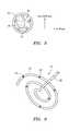
- FIG. 4is a distal perspective view of the access anchor of FIG. 2 ;
- FIG. 4Ais a cross-section view of the access anchor of FIG. 2 , particularly showing the mating of lead connectors therein;
- FIG. 5is a cross-sectional view of one embodiment of a pushable stimulation lead used in the kit of FIG. 1 , taken along the line 5 - 5 ;
- FIG. 6is a perspective view of the expanded distal end of the pushable stimulation lead of FIG. 1 ;
- FIG. 7is a perspective view of the expanded distal end of another embodiment of the pushable stimulation lead of FIG. 1 ;
- FIG. 8is an exploded perspective view of the expanded distal end of still another embodiment of the pushable stimulation lead of FIG. 1 ;
- FIG. 9is an integrated perspective view of the expanded distal end of the pushable stimulation lead of FIG. 8 ;
- FIG. 10is a cross-sectional view of the stimulation lead of FIG. 8 , taken along the line 10 - 10 ;
- FIG. 11is a cross-sectional view of the stimulation lead of FIG. 9 , taken along the line 11 - 11 ;
- FIG. 12is a plan view of an alternative embodiment of a sheathed stimulation lead that can be used in the kit of FIG. 1 , particularly showing expansion of the distal end of the stimulation lead;
- FIG. 13is a cross-sectional view of the sheathed stimulation lead of FIG. 12 , taken along the line 13 - 13 ;
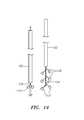
- FIG. 14is a plan view of another alternative embodiment of a sheathed stimulation lead that can be used in the kit of FIG. 1 , particularly showing expansion of the distal end of the stimulation lead;
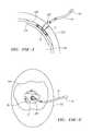
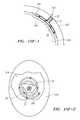
- FIGS. 15A-15Jillustrates a method for installing a stimulation lead within a patient using the kit of FIG. 1 .
- kits 10constructed in accordance with one preferred embodiment of the present invention.
- the kit 10can be used to stimulate cortical brain tissue in order to treat disorders, such as Parkinson's disease, epilepsy, and stroke, or the effects thereof.
- the kit 10generally comprises an access anchor 12 for providing convenient access to the patient's cortical brain tissue, an electrode lead, and in particular, a stimulation lead 14 for electrically stimulating the cortical brain tissue, and an implantable stimulation source 16 for providing stimulation energy to the stimulation lead 14 .
- the kit 10also comprises an optional tissue layer dissection device 18 for separating the dura mater from the cranium of the patient in order to form a pocket in which the stimulation lead 14 can be manipulated, as well as an optional extension lead 20 for electrically coupling the implanted stimulation source 16 to the stimulation lead 14 .
- the access anchor 12is configured for being mounted in a burr hole formed in the cranium of the patient.
- the burr hole in which the access anchor 12 is mountedis as small as possible, e.g., 2-3 millimeters in diameter, in contrast to prior art burr holes, which were on the order of 15 millimeters in diameter.
- the access anchor 12comprises a generally cylindrical rigid body 22 having a proximal end 24 and a distal end 26 .
- the diameter of the rigid body 22is preferably approximately equal to that of the burr hole.
- the rigid body 22may be composed of any suitable rigid and biocompatible material, such as stainless steel, titanium, metallic alloy, polysulfone, urethane, or polyimide.
- the rigid body 22is composed of an electrically non-conductive material in order to provide a robust means of electrical insulation between the stimulation lead 14 and the optional extension lead 20 , as will be described in further detail below.
- the access anchor 12further comprise a port 28 that extends through the entire length of the rigid body 22 .
- the port 28can be used to deliver and remove the stimulation lead 14 , optional tissue layer dissection device 18 , and other therapeutic and/or diagnostic devices to and from the patient's head as necessary.
- the access anchor 12further comprises self-tapping threads 30 disposed on the exterior of the rigid body 22 , so that the access anchor 12 will firmly anchor itself within the burr hole when rotated around its longitudinal axis. It can be appreciated that the diameter of the threads 30 is greater than the diameter of the burr hole, so that the threads 30 etch themselves into the bone tissue surrounding the burr hole when the access anchor 12 is mounted.
- the access anchor 12also comprises a driven mechanism 32 that can be used to facilitate its rotation within the burr hole.
- the driven mechanism 32takes the form of a hexagonal recess formed at the proximal end of the rigid body 22 .
- a driver mechanismsuch as an alien wrench (not shown), can be inserted into the hexagonal recess 32 and torqued in order to rotate the access anchor 12 against the frictional resistance exerted by the bone tissue.
- the hexagonal recess 32also functions as a female connector for the extension lead 20 , as will be described in further detail below.
- the stimulation lead 14comprises an elongated tubular body 34 having a proximal end 36 and a distal end 38 .
- the tubular body 34is composed of a suitably flexible material (such as polyurethane, polyethylene, silicone, PEBAX®, etc.), which may either be resilient or non-resilient, and may be formed via an extrusion process or by any other suitable means.
- the tubular body 34is cylindrically-shaped, but may have other cross-sectional geometries, such as oval, rectangular, triangular, etc.
- the stimulation lead 14further comprises a plurality of segmented electrodes 40 mounted along the distal end 38 of the elongated tubular body 34 , and a connector 42 mounted on the proximal end 36 of the tubular body 34 .
- the electrodes 40are electrically coupled to the connector 42 via signal wires 44 extending through the tubular body 34 .
- the stimulation lead 14may be arranged such that signals can be independently transmitted to the electrodes 40 either in a monopolar or bipolar arrangement, in which case, the stimulation lead will have multiple channels, or may be arranged such that a signal is simultaneously transmitted to multiple electrodes.
- the segmented electrodes 40may comprise, e.g., solid rings of a biocompatible and electrically conductive material, such as platinum, copper alloy, stainless steel, or nitinol.
- the electrically conducting material of the electrodes 40can be further coated with platinum-iridium or gold to improve their conduction properties, biocompatibility, and radiopacity.
- the connector 42is shaped and sized to be interference fitted within the port 28 of the access anchor 28 , such as, e.g., using a snap-fit configuration.
- the stimulation lead 14is configured for being linearly delivered through the access anchor port 28 .
- the outer diameter of the tubular body 34is slightly smaller than the diameter of the access anchor port 28 , so that the stimulation lead 14 can more easily pass in and out of the port 28 .
- the stimulation lead 14is also configured for being expanded into a pre-shaped two-dimensional geometry, as illustrated in FIG. 6 , which for the purposes of this specification, is any geometry that is planar or curviplanar.
- the stimulation lead 14comprises a pre-shaped resilient center support 46 that extends through the tubular body 34 in a fixed manner and urges the stimulation lead 14 into the two-dimensional geometry.
- the center support 46also provides the stimulation lead 14 with axial rigidity to facilitate its introduction through the access anchor 12 and between the patient's cortical brain tissue and cranium, and in particular, between the dura mater covering the cortical brain tissue and the cranium.
- the center support 46may be composed of any relatively stiff and resilient material, such as stainless steel, a metallic and polymer material, or a high-stiffness urethane or silicone, that is shaped into the desired geometry.
- the center support 46may be composed of a shape memory material, such as nitinol, so that it assumes the desired geometry in the presence of a defined temperature, such as, e.g., body temperature.
- the stimulation lead 14is configured as a pushable design, meaning that as the stimulation lead 14 is introduced through the access anchor 12 , the distal end 38 of the stimulation lead 14 will expand into its two-dimensional geometry between the dura mater and cranium.
- the two-dimensional geometry assumed by the expandable distal end 38 of the stimulation lead 14is a coil that outwardly winds over the dura mater as the stimulation lead 14 is advanced through the access anchor 12 , as will be described in further detail below. As illustrated in FIG.
- the cross-section of the center support 46is rectangular, with the longer edges of the cross-section being orientated out-of-plane and the shorter edges of the cross-section being in-plane, so that the coil more easily winds in-plane between the cortical tissue and cranium of the patient.
- the expandable distal end 38 of the stimulation lead 14is pre-shaped to lie in a plane that is orthogonal to the proximal end of the stimulation lead 14 .
- the stimulation lead 54is similar to the previously described stimulation lead 14 , with the exception that it includes a monitoring lumen 56 that can be used to aspirate blood or cerebral spinal fluid (CSF) from the patient's head or introduce a small diameter scope (not shown) within the patient's head. In this manner, leakage of CSF, or worse yet, leakage of blood, can be monitored, and remedial measures can be taken if necessary.
- the monitoring lumen 56externally extends down one side of the tubular body 34 .
- the monitoring lumen 56can be formed onto the tubular body 34 in any suitable manner, for example, bonding the monitoring lumen 56 to the side of the tubular body 34 , or coextruding the tubular body 34 and monitoring lumen 56 together.
- an external monitoring lumenincreases the profile of the stimulation lead 54 , which may disadvantageously result in an increase in the burr hole in which the access anchor 12 is mounted.
- a stimulation lead 64 with an internal monitoring lumencan be used.
- the stimulation lead 54is similar to the previously described stimulation lead 14 , with the exception that, rather than a fixed center support 46 , it comprises an internal monitoring lumen 66 and a stilette 68 removably disposed within the monitoring lumen 66 .
- the stilette 68can be composed of the same material and be pre-shaped in the same manner as the center support 46 .
- the stilette 68can be inserted into the monitoring lumen 66 in order to facilitate introduction of the stimulation lead 64 through the access anchor 12 and expansion of the distal end of the stimulation lead 64 into the desired two-dimensional geometry, in this case, a coil.
- the stilette 68can be removed from the monitoring lumen 66 , after which, the empty monitoring lumen 66 may serve either as an aspiration lumen or as a means for introducing the small bore scope into the patient's head for detection of any CSF or blood leaks.
- the cross-section of the monitoring port 28as well as the stilette 68 , is circular, in order to facilitate introduction of the bore scope, which will typically have a circular cross-section.
- monitoring lumenscan also be used to introduce other devices or agents into the patient's head.
- the monitoring lumenscan be used to perform functional mapping using voltage or current sensing dyes, direct spectroscopy, or indirect optical measurement of physiological parameters, such as oxy- to deoxyhemogoblin transitions. This will produce convergent information used to enhance physiological mapping of regions, such as eloquent neocortex or areas of pathophysiology like epileptic foci, or dysgenic cortex.
- stimulation leadscan also be configured as a sheath design, meaning that the stimulation lead is configured to be introduced through the access anchor 12 using a sheath that maintains the stimulation lead in a collapsed or linear geometry, while providing the axial strength necessary to manipulate the stimulation lead between the dura mater and cranium. The sheath can then be pulled back to deploy or place the stimulation lead into an expanded two-dimensional geometry between the dura mater and cranium.
- FIG. 12illustrates one embodiment of a stimulation lead 104 that can be delivered through the access anchor 12 with a sheath 102 .
- the stimulation lead 104comprises a spring element 106 having a proximal end 108 and a distal end 110 , a plurality of electrodes 112 mounted along the distal end 110 of the spring element 106 , and a connector 112 mounted on the proximal end 108 of the spring element 106 .
- the electrodes 112are electrically coupled to the connector 42 via insulated signal wires 114 (shown in FIG. 13 ) extending through the spring element 106 .
- the stimulation lead 104may be arranged such that signals can be independently transmitted to the electrodes 112 either in a monopolar or bipolar arrangement, in which case, the stimulation lead 104 will have multiple channels, or may be arranged such that a signal is simultaneously transmitted to multiple electrodes.
- the spring element 106comprises an electrically insulative layer (not shown) between the electrodes 112 in order to electrically isolate the electrodes 112 .
- the electrodes 112can be formed onto the spring element 106 using known deposition processes, such as sputtering, vapor deposition, ion beam deposition, electroplating over a deposited seed layer, or a combination of these processes. Or the electrodes can be discrete elements that are suitably mounted to the spring element 106 .
- the electrodes 112may be composed of the same material as the previously described segmented electrodes 112 .
- the spring element 106is composed of any relatively stiff and resilient material, such as stainless steel, a metallic and polymer material, or a high-stiffness urethane or silicone, that is shaped into the desired geometry.
- the spring element 106may be composed of a shape memory material, such as nitinol, so that it assumes the desired geometry in the presence of a defined temperature, such as, e.g., body temperature.
- a defined temperaturesuch as, e.g., body temperature.
- the spring element 106has a planar geometry in that it has a minimal thickness (height) as compared to its width.
- the stimulation lead 104may be more easily manipulated between the cortical brain tissue and cranium.
- the spring element 106can be made from wire, which is cylindrical in nature.
- the spring element 106is formed of a single linear element that longitudinally extends in a meandering fashion.
- the laterally extending curves of the meandering spring element 106provide the necessary spring force to urge the distal end of the stimulation lead 104 from its low-profile collapsed geometry into an expanded two-dimensional geometry.
- the stimulation lead 104lacks pushability.
- the sheath 102is used to deliver the stimulation lead 104 , in its collapsed geometry, through the access anchor 12 and between the dura mater and cranium. The sheath 102 can then be removed to place the distal end of the stimulation lead 104 into its expanded geometry.
- the sheath 102can be provided with an optional monitoring lumen (not shown) to detect any CSF or blood through aspiration or visualization with a scope.
- a sheath-type stimulation leadmay have other expanded geometries besides the meandering geometry illustrated in FIG. 12 .
- FIG. 14illustrates a stimulation lead 124 that is similar to the previously described stimulation lead 104 , with the exception that it comprises a main spring element 126 that extends along a straight line and a plurality of lateral spring elements 128 that branch off of the main spring segment 124 , with each lateral spring element 126 carrying an electrode 112 .
- the lateral spring elements 126act to provide the necessary spring force to urge the distal end of the stimulation lead 124 from its low-profile collapsed geometry into an expanded two-dimensional geometry.
- the sheath 102can be used to deliver the stimulation lead 124 , in its collapsed geometry, through the access anchor 12 and between the dura mater and cranium. The sheath 102 can then be removed to place the distal end of the stimulation lead 124 into its expanded geometry.
- the tissue layer dissection device 18is configured to separate the dura mater from the cranium to create a pocket in which the stimulation lead 14 will be expanded.
- the dissection device 18comprises an elongated shaft 70 having a proximal end 72 and a distal end 74 , an expandable balloon 76 mounted to the distal end 74 of the shaft 70 , and an inflation port 78 mounted to the proximal end 72 of the shaft 70 .
- the elongated shaft 70is composed of a rigid material, such as stainless steel, but can alternatively be composed of a semi-rigid or flexible material.
- the inflation port 78is in fluid communication with the interior of the balloon 76 via a lumen (not shown).
- an inflation mediumsuch as saline
- salinecan be introduced through the inflation port 78 under pressure in order to expand the balloon 76 (as shown in phantom), and the inflation medium can be removed from the inflation port 78 to deflate the balloon 76 .
- the balloon 76when expanded, assumes a planar-like radial geometry that resembles the shape of the intended pocket to be created, and in particular, the pocket between the dura mater and cranium. It can be appreciated that this planar-like pocket, while minimizing unnecessary displacement and trauma to surrounding tissue, such as the cortical brain tissue, provides the necessary space to allow navigation and expansion of the low-profile stimulation lead 14 within the patient's head. To further minimize unnecessary displacement and trauma to the cortical brain tissue, the balloon 76 is composed of a compliant material, such as silicone.
- the balloon 76may be composed of a semi-compliant material, such as SELAR®, or a non-compliant material, such as PET, although additional care must be taken when expanding the balloon 76 within the patient's head.
- the tissue layer dissection device 18may optionally comprise an external or internal monitoring lumen (not shown) similar to that incorporated into the tubular bodies of the stimulation lead 54 , 64 illustrated in FIGS. 7 and 8 .
- any leakage of CSF or blood caused by creation of the pocketcan be detected via its aspiration through the monitoring lumen or a small-bore scope can be introduced through the monitoring lumen to visualize such leakage.
- the extension lead 20is configured to be coupled between the stimulation lead 14 via the access anchor 12 and the implantable stimulation source 16 .
- the extension lead 20comprises an electrically insulative sheath 80 having a proximal end 82 and a distal end 84 , a distal connector 86 mounted on the distal end 84 of the sheath 80 , a proximal connector 88 mounted on the proximal end 82 of the sheath 80 , and wire conductors (not shown) that extend through the length of the sheath between the respective connectors 86 , 88 .
- wire conductorsnot shown
- the distal connector 86 of the extension lead 20is configured to mate with the connector 42 of the stimulation lead 14 , which will be in a snap-fit arrangement with the port 28 of the access anchor 12 .
- the connector 86has a hexagonal shape that allows it to be interference fit within the hexagonal recess 32 of the access anchor 12 using, e.g., a snap fit connection.
- the distal connector 86 of the extension lead 20comprises pins 90 that are configured to be received into pin receptacles 92 within the connector 42 of the stimulation lead 14 .
- the proximal connector 88can be mated with the stimulation source 16 in a standard manner.
- the length of the extension lead 20is preferably sized to extend from the mounted access anchor 12 to the implant location of the stimulation source 16 .
- the length of the stimulation lead 14may be in the range of 50 cm to 100 cm. If, however, the stimulation source 16 is to be implanted in the abdomen or groin area of the patient, the length of the stimulation lead 14 may be in the range of 150 cm to 300 cm.
- the implantable stimulation source 16is designed to deliver electrical pulses to the stimulation lead 12 in accordance with programmed parameters.
- the stimulation source 16is programmed to output electrical pulses having amplitudes varying from 0.1 to 20 volts, pulse widths varying from 0.02 to 2 milliseconds, and repetition rates varying from 2 to 2500 Hertz.
- the stimulation source 16takes the form of a totally self-contained generator, which once implanted, may be activated by a small magnet and/or controlled by an outside telemetry source that transmits programmed parameters to the pulse generator and monitors the performance of the pulse generator, e.g., a small magnet.
- the pulse generatorhas an internal power source that limits the life of the pulse generator to a few years, and after the power source is expended, the pulse generator must be replaced.
- these types of stimulation sourcesmay be implanted within the chest or abdominal region beneath the skin of the patient.
- the implantable stimulation source 16may take the form of a passive receiver that receives radio frequency (RF) signals from an external transmitter worn by the patient.
- RFradio frequency
- the receivers of these types of stimulation sourcescan be implanted within the chest or abdominal region beneath the skin of the patient.
- the receiversmay also be suitable for implantation behind the ear of the patient, in which case, the external transmitter may be worn on the ear of the patient in a manner similar to that of a hearing aid.
- Stimulation sourcessuch as those just described, are commercially available from Medtronic, Inc., located in Minneapolis, Minn. Further details regarding the construction of a stimulation source for the purpose of treating neurological disorders is disclosed in U.S. Pat. No. 5,716,377, which is expressly incorporated herein by reference.
- the stimulation source 16may be connected to the stimulation lead 14 or multiple stimulation leads in any one of a variety of manners.
- each stimulation lead 14can be connected in a unipolar arrangement or a bipolar or multipolar arrangement or multiple stimulation leads can be connected together in a bipolar arrangement, further details of which are described in U.S. Patent Application Publication 2005/0137646 A1, previously abandoned, which has previously be incorporated herein by reference.
- cortical brain tissue stimulation kit 10Having described the construction and function of the cortical brain tissue stimulation kit 10 , a preferred method of installing it in the patient's head to treat a diagnosed disorder via cortical brain tissue stimulation will now be described with reference to FIGS. 15A-15J .
- a standard imaging systemsuch as Computed Tomography (CT), Computed Tomography Angiography (CTA) or Digital Angiography can be used to facilitate installation of the kit 10 .
- CTComputed Tomography
- CTAComputed Tomography
- Digital AngiographyDigital Angiography
- a relative small burr hole 200(e.g., 2-3 millimeter diameter) is drilled through the patient's cranium 202 to access the underlying dura mater 204 that protects the cortical brain tissue 206 ( FIG. 15A ).
- the access anchor 12is installed within the burr hole 200 by inserting the distal end of the access anchor 12 into the burr hole 200 and rotating the access anchor 12 the access anchor 12 until it is flush with the external surface of the cranium 202 ( FIG. 15B ).
- the driven mechanism 32can be engaged with an allen wrench (not shown) to rotate the access anchor 12 . As previously described above, the recessed driven mechanism 32 will avoid any protrusion of the access anchor 12 from the cranium 202 .
- the tissue layer dissection device 18be used to separate the dura mater 204 from the cranium 202 .
- the tissue layer dissection device 18while the balloon 76 is in its deflated geometry, is introduced through the port 28 of the access anchor 12 until the distal end 74 of the dissection device 18 contacts the dura mater 204 ( FIG. 15C ).
- inflation mediumis introduced through the inflation port 78 of the dissection device 18 , thereby inflating the balloon 76 , which will expand radially outward in a planar geometry to separate the dura mater 204 from the cranium 202 to create a pocket 208 therebetween ( FIG. 15D ).
- the dissection device 18has an optional monitoring lumen, any CSF or blood leakage can be detected simply be checking to see if CSF or blood is aspirated through the monitoring lumen or by placing a scope through the monitoring lumen and internally visualizing any fluid leakage.
- the balloon 76is then deflated by removing the inflation medium from the inflation port 78 of the dissection device 18 , which is then removed from the patient's head via the access anchor 12 .
- a stimulation leadis introduced through the port 28 of the access anchor 12 into the pocket, where it is placed in its expanded geometry between the dura mater 204 and cranium 202 .
- the details of this stepwill ultimately depend on the type of stimulation lead used. For example, if the pushable stimulation lead 14 illustrated in FIG. 6 (or alternatively, the pushable stimulation leads 54 , 54 illustrated in FIGS. 7 and 8 ) is used, the stimulation lead 14 will be linearly introduced (i.e., by threading) through the port 28 of the access anchor 12 ( FIG. 15E-1 ). Advancement of the stimulation lead 14 will automatically cause the distal end 38 of the stimulation lead 14 to expand by outwardly winding ( FIG. 15E-2 ).
- the stimulation lead 14will continue to be advanced through the access anchor 12 until the connector 42 of the stimulation lead 14 mates within the port 28 of the access anchor 12 ( FIG. 15F-1 ) (see FIG. 4A for details), during which the distal end 38 of the stimulation lead 14 will be fully expanded between the dura mater 204 and cranium 202 ( FIG. 15F-2 ).
- the sheath 102 , along with the collapsed stimulation lead 104 , 124will be threaded through the port 28 of the access anchor 12 and into the pocket 208 formed between the dura mater 204 and cranium 202 until the distal tip of the sheath 102 lies at the distal-most portion of the pocket 208 ( FIG. 15G ).
- the sheath 102will then be pulled back and removed to expose the distal ends of the stimulation leads 104 , 124 , which will then fully expand between the dura mater 204 and cranium 202 ( FIGS. 15H-1 and 15 H- 2 ).
- the stimulation lead 104 , 124will be further advanced through the access anchor 12 until the connector 42 of the stimulation lead 104 , 124 mates within the port 28 of the access anchor 12 in the same manner illustrated in FIGS. 15F-1 and 15 F- 2 .
- the stimulation lead 14may be left within the patient's head either acutely (i.e., only during an operation and then removed after the operation has been completed), chronically, or sub-chronically (i.e., less than six months).
- the distal connector 42 of the extension lead 20(which as described above takes the form of a male hexagonal connector) is snap fit into the hexagonal recess 32 of the access anchor 12 and mated with the connector 42 of the stimulation lead 14 ( FIG. 15I ) (see FIG. 4A for details).
- the extension lead 20can then be subcutaneously routed to the clavical or chest region or the abdominal or groin region of the patient, where it can be coupled to the implanted stimulation source 16 ( FIG. 15J ).
- the stimulation source 16may not be implanted, but rather located exterior to the patient. e.g., during a non-chronic procedure.
- the stimulation kit 10is designed to minimize the number of burr holes made within the patient's cranium, the steps illustrated in FIGS. 15A-15F and 151 - 15 J (if pushable stimulation leads are used) and FIGS. 15A-15D and 15 G- 15 J (if sheathed stimulation leads are used) can be repeated if additional stimulation leads are to be placed within the pocket 208 between the dura mater 204 and cranium 202 .
- the stimulation source 16can then be operated to transmit stimulation energy to the stimulation lead 14 (or stimulation leads 54 , 64 , 104 , or 124 ), which delivers the stimulation energy to the cortical brain tissue 206 through the dura mater 204 .
Landscapes
- Health & Medical Sciences (AREA)
- Neurology (AREA)
- Neurosurgery (AREA)
- Psychology (AREA)
- Cardiology (AREA)
- Heart & Thoracic Surgery (AREA)
- Engineering & Computer Science (AREA)
- Biomedical Technology (AREA)
- Nuclear Medicine, Radiotherapy & Molecular Imaging (AREA)
- Radiology & Medical Imaging (AREA)
- Life Sciences & Earth Sciences (AREA)
- Animal Behavior & Ethology (AREA)
- General Health & Medical Sciences (AREA)
- Public Health (AREA)
- Veterinary Medicine (AREA)
- Electrotherapy Devices (AREA)
Abstract
Description
Claims (21)
Priority Applications (1)
| Application Number | Priority Date | Filing Date | Title |
|---|---|---|---|
| US11/010,232US7937160B2 (en) | 2004-12-10 | 2004-12-10 | Methods for delivering cortical electrode leads into patient's head |
Applications Claiming Priority (1)
| Application Number | Priority Date | Filing Date | Title |
|---|---|---|---|
| US11/010,232US7937160B2 (en) | 2004-12-10 | 2004-12-10 | Methods for delivering cortical electrode leads into patient's head |
Publications (2)
| Publication Number | Publication Date |
|---|---|
| US20060129203A1 US20060129203A1 (en) | 2006-06-15 |
| US7937160B2true US7937160B2 (en) | 2011-05-03 |
Family
ID=36585069
Family Applications (1)
| Application Number | Title | Priority Date | Filing Date |
|---|---|---|---|
| US11/010,232Expired - Fee RelatedUS7937160B2 (en) | 2004-12-10 | 2004-12-10 | Methods for delivering cortical electrode leads into patient's head |
Country Status (1)
| Country | Link |
|---|---|
| US (1) | US7937160B2 (en) |
Cited By (14)
| Publication number | Priority date | Publication date | Assignee | Title |
|---|---|---|---|---|
| US20090030479A1 (en)* | 2005-07-11 | 2009-01-29 | Mcintyre Jon T | Percutaneous Access for Neuromodulation Procedures |
| US20110224528A1 (en)* | 2008-10-08 | 2011-09-15 | Korea Institute Of Science And Technology | flexible, multi-channel microelectrode for recording laboratory animal eeg and method for recording laboratory animal eeg using the same |
| US20140148805A1 (en)* | 1999-04-05 | 2014-05-29 | Medtronic, Inc. | Ablation catheters and associated systems and methods |
| US9179875B2 (en) | 2009-12-21 | 2015-11-10 | Sherwin Hua | Insertion of medical devices through non-orthogonal and orthogonal trajectories within the cranium and methods of using |
| US9675413B2 (en) | 2002-04-08 | 2017-06-13 | Medtronic Ardian Luxembourg S.A.R.L. | Methods and apparatus for renal neuromodulation |
| US9855096B2 (en) | 2012-05-11 | 2018-01-02 | Medtronic Ardian Luxembourg S.A.R.L. | Multi-electrode catheter assemblies for renal neuromodulation and associated systems and methods |
| US10314614B2 (en) | 2009-06-19 | 2019-06-11 | Medtronic, Inc. | Arcuate introducer |
| US10736690B2 (en) | 2014-04-24 | 2020-08-11 | Medtronic Ardian Luxembourg S.A.R.L. | Neuromodulation catheters and associated systems and methods |
| US10792098B2 (en) | 2013-03-15 | 2020-10-06 | Medtronic Ardian Luxembourg S.A.R.L. | Helical push wire electrode |
| US20210236042A1 (en)* | 2018-05-01 | 2021-08-05 | Mayo Foundation For Medical Education And Research | Intracranial electrode and delivery system |
| US11160580B2 (en) | 2019-04-24 | 2021-11-02 | Spine23 Inc. | Systems and methods for pedicle screw stabilization of spinal vertebrae |
| US11759238B2 (en) | 2008-10-01 | 2023-09-19 | Sherwin Hua | Systems and methods for pedicle screw stabilization of spinal vertebrae |
| US12076058B2 (en) | 2021-05-12 | 2024-09-03 | Spine23 Inc. | Systems and methods for pedicle screw stabilization of spinal vertebrae |
| US12268422B2 (en) | 2019-11-27 | 2025-04-08 | Spine23 Inc. | Systems, devices and methods for treating a lateral curvature of a spine |
Families Citing this family (34)
| Publication number | Priority date | Publication date | Assignee | Title |
|---|---|---|---|---|
| US7590454B2 (en)* | 2004-03-12 | 2009-09-15 | Boston Scientific Neuromodulation Corporation | Modular stimulation lead network |
| US20050203600A1 (en)* | 2004-03-12 | 2005-09-15 | Scimed Life Systems, Inc. | Collapsible/expandable tubular electrode leads |
| US9307925B2 (en) | 2005-06-16 | 2016-04-12 | Aaken Laboratories | Methods and systems for generating electrical property maps of biological structures |
| US8068892B2 (en)* | 2005-06-16 | 2011-11-29 | Aaken Labs | Methods and systems for using intracranial electrodes |
| FR2909883B1 (en)* | 2006-12-18 | 2012-11-30 | Commissariat Energie Atomique | MULTI-ARM SENSOR AND SYSTEM FOR DEEP ELECTRICAL NEUROSTIMULATION COMPRISING SUCH A PROBE |
| US20080154331A1 (en)* | 2006-12-21 | 2008-06-26 | Varghese John | Device for multicentric brain modulation, repair and interface |
| KR100865950B1 (en)* | 2007-07-11 | 2008-11-03 | 김형일 | Epidural electrode using shape memory alloy |
| US20090118786A1 (en)* | 2007-11-02 | 2009-05-07 | Advanced Bionics Corporation | Automated fitting system for deep brain stimulation |
| US9248280B2 (en)* | 2007-11-02 | 2016-02-02 | Boston Scientific Neuromodulation Corporation | Closed-loop feedback for steering stimulation energy within tissue |
| US20090118804A1 (en)* | 2007-11-05 | 2009-05-07 | Advanced Bionics Corporation | Method of mounting minimally invasive plug electrodes within cranium of patient |
| US20110029055A1 (en)* | 2008-04-21 | 2011-02-03 | Medronic, Inc. | Spiral lead |
| US20090306750A1 (en)* | 2008-06-06 | 2009-12-10 | Neuropace, Inc. | Lead Fixation Assembly and Methods of Using Same |
| CA2732309C (en) | 2008-07-30 | 2018-04-10 | Ecole Polytechnique Federale De Lausanne (Epfl) | Apparatus and method for optimized stimulation of a neurological target |
| DE102008048788B4 (en)* | 2008-09-24 | 2012-07-26 | Dr. Langer Medical Gmbh | Electrode for intraoperative nerve stimulation |
| JP5667987B2 (en)* | 2008-11-12 | 2015-02-12 | エコーレ ポリテクニーク フェデラーレ デ ローザンヌ (イーピーエフエル) | Micromachined nerve stimulation device |
| US9044588B2 (en)* | 2009-04-16 | 2015-06-02 | Cochlear Limited | Reference electrode apparatus and method for neurostimulation implants |
| KR101108739B1 (en) | 2009-07-15 | 2012-02-16 | 김형일 | Wireless implantable electrical cortical stimulation apparatus |
| CA2782710C (en) | 2009-12-01 | 2019-01-22 | Ecole Polytechnique Federale De Lausanne | Microfabricated neurostimulation device and methods of making and using the same |
| US20120302857A1 (en)* | 2010-01-25 | 2012-11-29 | Kyushu Institute Of Technology | Brain signal measurement system and measurement system |
| CN102198308A (en)* | 2010-03-26 | 2011-09-28 | 苏州鼎迈医疗科技有限公司 | Extension lead of implanted nervous electrical stimulation system |
| CA2795159C (en) | 2010-04-01 | 2020-11-03 | Ecole Polytechnique Federale De Lausanne | Device for interacting with neurological tissue and methods of making and using the same |
| US8818525B2 (en) | 2011-02-11 | 2014-08-26 | Medtronic, Inc. | Lead having thin distal end portion |
| US9610437B2 (en) | 2013-08-01 | 2017-04-04 | University Of Florida Research Foundation, Inc. | Apparatuses and methods for securing deep brain stimulation leads |
| US11311718B2 (en) | 2014-05-16 | 2022-04-26 | Aleva Neurotherapeutics Sa | Device for interacting with neurological tissue and methods of making and using the same |
| WO2015173787A1 (en) | 2014-05-16 | 2015-11-19 | Aleva Neurotherapeutics Sa | Device for interacting with neurological tissue and methods of making and using the same |
| US9403011B2 (en) | 2014-08-27 | 2016-08-02 | Aleva Neurotherapeutics | Leadless neurostimulator |
| US9925376B2 (en) | 2014-08-27 | 2018-03-27 | Aleva Neurotherapeutics | Treatment of autoimmune diseases with deep brain stimulation |
| US9474894B2 (en) | 2014-08-27 | 2016-10-25 | Aleva Neurotherapeutics | Deep brain stimulation lead |
| EP3541465A4 (en)* | 2016-11-16 | 2020-08-05 | Ramot at Tel-Aviv University Ltd. | INTRACRANIAL VOLUME ADAPTER FOR CEREBRAL BLOOD FLOW |
| US10702692B2 (en) | 2018-03-02 | 2020-07-07 | Aleva Neurotherapeutics | Neurostimulation device |
| WO2019195707A1 (en)* | 2018-04-06 | 2019-10-10 | Medtronic, Inc. | Cranial implant for device fixation in burr holes |
| WO2020264041A1 (en)* | 2019-06-24 | 2020-12-30 | Neuroone Medical Technologies Corporation | Minimally invasive electrode and delivery device and related systems and methods |
| EP4188221A4 (en) | 2020-08-03 | 2024-07-31 | Neuroone Medical Technologies Corporation | METHOD OF MANUFACTURING PROBE DEVICES AND RELATED DEVICES |
| EP4518955B1 (en)* | 2022-05-06 | 2025-06-18 | Ecole Polytechnique Federale De Lausanne (Epfl) | Implantable electrical/electronic biomedical device. |
Citations (178)
| Publication number | Priority date | Publication date | Assignee | Title |
|---|---|---|---|---|
| US538514A (en) | 1895-04-30 | haeselee | ||
| US661047A (en) | 1900-08-29 | 1900-11-06 | Elbert G Graves | Cultivator and planter. |
| US4141365A (en) | 1977-02-24 | 1979-02-27 | The Johns Hopkins University | Epidural lead electrode and insertion needle |
| US4285347A (en) | 1979-07-25 | 1981-08-25 | Cordis Corporation | Stabilized directional neural electrode lead |
| US4519403A (en) | 1983-04-29 | 1985-05-28 | Medtronic, Inc. | Balloon lead and inflator |
| US4608985A (en) | 1984-10-11 | 1986-09-02 | Case Western Reserve University | Antidromic pulse generating wave form for collision blocking |
| US4658835A (en) | 1985-07-25 | 1987-04-21 | Cordis Corporation | Neural stimulating lead with fixation canopy formation |
| US4739768A (en) | 1986-06-02 | 1988-04-26 | Target Therapeutics | Catheter for guide-wire tracking |
| US4813934A (en) | 1987-08-07 | 1989-03-21 | Target Therapeutics | Valved catheter device and method |
| US4869255A (en) | 1987-12-04 | 1989-09-26 | Ad-Tech Medical Instrument Corp. | Electrical connection device |
| US4884579A (en) | 1988-04-18 | 1989-12-05 | Target Therapeutics | Catheter guide wire |
| US5005587A (en) | 1989-11-13 | 1991-04-09 | Pacing Systems, Inc. | Braid Electrode leads and catheters and methods for using the same |
| US5010894A (en) | 1988-01-07 | 1991-04-30 | Edhag Knut O | Intravascular electrode lead usable for cardiac defibrillation |
| US5010895A (en) | 1989-08-03 | 1991-04-30 | Empi, Inc. | Expandable vaginal electrode |
| US5107856A (en) | 1991-01-10 | 1992-04-28 | Siemens-Pacesetter, Inc. | Multiple lead suture sleeve |
| US5170802A (en) | 1991-01-07 | 1992-12-15 | Medtronic, Inc. | Implantable electrode for location within a blood vessel |
| US5224491A (en) | 1991-01-07 | 1993-07-06 | Medtronic, Inc. | Implantable electrode for location within a blood vessel |
| US5234437A (en) | 1991-12-12 | 1993-08-10 | Target Therapeutics, Inc. | Detachable pusher-vasoocclusion coil assembly with threaded coupling |
| US5239999A (en) | 1992-03-27 | 1993-08-31 | Cardiac Pathways Corporation | Helical endocardial catheter probe |
| US5250071A (en) | 1992-09-22 | 1993-10-05 | Target Therapeutics, Inc. | Detachable embolic coil assembly using interlocking clasps and method of use |
| US5261916A (en) | 1991-12-12 | 1993-11-16 | Target Therapeutics | Detachable pusher-vasoocclusive coil assembly with interlocking ball and keyway coupling |
| US5263488A (en) | 1992-10-05 | 1993-11-23 | Nicolet Instrument Corporation | Method and apparatus for localization of intracerebral sources of electrical activity |
| US5304195A (en) | 1991-12-12 | 1994-04-19 | Target Therapeutics, Inc. | Detachable pusher-vasoocclusive coil assembly with interlocking coupling |
| US5306272A (en)* | 1992-11-02 | 1994-04-26 | Neuro Navigational Corporation | Advancer for surgical instrument |
| US5312415A (en) | 1992-09-22 | 1994-05-17 | Target Therapeutics, Inc. | Assembly for placement of embolic coils using frictional placement |
| US5342410A (en) | 1990-10-05 | 1994-08-30 | Eric Braverman | Apparatus and method for increasing the amplitude of P300 waves in the human brain |
| US5350397A (en) | 1992-11-13 | 1994-09-27 | Target Therapeutics, Inc. | Axially detachable embolic coil assembly |
| US5358514A (en) | 1991-12-18 | 1994-10-25 | Alfred E. Mann Foundation For Scientific Research | Implantable microdevice with self-attaching electrodes |
| US5365926A (en) | 1986-11-14 | 1994-11-22 | Desai Jawahar M | Catheter for mapping and ablation and method therefor |
| US5374285A (en) | 1992-07-31 | 1994-12-20 | Aries S.R.L. | Spinal electrode catheter |
| US5391200A (en) | 1992-09-30 | 1995-02-21 | Cardiac Pacemakers, Inc. | Defibrillation patch electrode having conductor-free resilient zone for minimally invasive deployment |
| US5397341A (en) | 1992-03-16 | 1995-03-14 | Siemens Elema Ab | Defibrillation electrode |
| US5411551A (en) | 1992-08-05 | 1995-05-02 | Ultrasonic Sensing And Monitoring Systems, Inc. | Stent assembly with sensor |
| US5417719A (en) | 1993-08-25 | 1995-05-23 | Medtronic, Inc. | Method of using a spinal cord stimulation lead |
| US5423864A (en) | 1992-12-11 | 1995-06-13 | Siemens Elema Ab | Difibrillation system |
| US5423877A (en) | 1992-05-04 | 1995-06-13 | David C. Mackey | Method and device for acute pain management by simultaneous spinal cord electrical stimulation and drug infusion |
| US5443492A (en) | 1994-02-02 | 1995-08-22 | Medtronic, Inc. | Medical electrical lead and introducer system for implantable pulse generator |
| US5462545A (en)* | 1994-01-31 | 1995-10-31 | New England Medical Center Hospitals, Inc. | Catheter electrodes |
| US5464446A (en)* | 1993-10-12 | 1995-11-07 | Medtronic, Inc. | Brain lead anchoring system |
| US5501703A (en) | 1994-01-24 | 1996-03-26 | Medtronic, Inc. | Multichannel apparatus for epidural spinal cord stimulator |
| US5509411A (en) | 1993-01-29 | 1996-04-23 | Cardima, Inc. | Intravascular sensing device |
| US5531779A (en) | 1992-10-01 | 1996-07-02 | Cardiac Pacemakers, Inc. | Stent-type defibrillation electrode structures |
| US5534007A (en) | 1995-05-18 | 1996-07-09 | Scimed Life Systems, Inc. | Stent deployment catheter with collapsible sheath |
| US5543864A (en) | 1994-10-11 | 1996-08-06 | Hudson Optical Corporation | Method and kit for attaching side shields to eyeglass temples |
| US5582609A (en) | 1993-10-14 | 1996-12-10 | Ep Technologies, Inc. | Systems and methods for forming large lesions in body tissue using curvilinear electrode elements |
| US5603731A (en) | 1994-11-21 | 1997-02-18 | Whitney; Douglass G. | Method and apparatus for thwarting thrombosis |
| US5611345A (en) | 1995-04-24 | 1997-03-18 | Hibbeln; John F. | Medical instrument with improved ultrasonic visibility |
| US5647870A (en) | 1993-03-16 | 1997-07-15 | Ep Technologies, Inc. | Multiple electrode support structures |
| US5683422A (en) | 1996-04-25 | 1997-11-04 | Medtronic, Inc. | Method and apparatus for treating neurodegenerative disorders by electrical brain stimulation |
| US5702438A (en) | 1995-06-08 | 1997-12-30 | Avitall; Boaz | Expandable recording and ablation catheter system |
| US5707354A (en) | 1995-04-17 | 1998-01-13 | Cardiovascular Imaging Systems, Inc. | Compliant catheter lumen and methods |
| US5713922A (en) | 1996-04-25 | 1998-02-03 | Medtronic, Inc. | Techniques for adjusting the locus of excitation of neural tissue in the spinal cord or brain |
| US5716377A (en) | 1996-04-25 | 1998-02-10 | Medtronic, Inc. | Method of treating movement disorders by brain stimulation |
| US5752979A (en) | 1996-11-01 | 1998-05-19 | Medtronic, Inc. | Method of controlling epilepsy by brain stimulation |
| US5755750A (en) | 1995-11-13 | 1998-05-26 | University Of Florida | Method and apparatus for selectively inhibiting activity in nerve fibers |
| US5782239A (en) | 1992-06-30 | 1998-07-21 | Cordis Webster, Inc. | Unique electrode configurations for cardiovascular electrode catheter with built-in deflection method and central puller wire |
| US5782798A (en) | 1996-06-26 | 1998-07-21 | Medtronic, Inc. | Techniques for treating eating disorders by brain stimulation and drug infusion |
| US5792187A (en) | 1993-02-22 | 1998-08-11 | Angeion Corporation | Neuro-stimulation to control pain during cardioversion defibrillation |
| US5800474A (en) | 1996-11-01 | 1998-09-01 | Medtronic, Inc. | Method of controlling epilepsy by brain stimulation |
| EP0865800A2 (en) | 1997-03-17 | 1998-09-23 | Medtronic, Inc. | Medical electrical lead |
| US5814062A (en) | 1994-12-22 | 1998-09-29 | Target Therapeutics, Inc. | Implant delivery assembly with expandable coupling/decoupling mechanism |
| US5846238A (en) | 1996-01-19 | 1998-12-08 | Ep Technologies, Inc. | Expandable-collapsible electrode structures with distal end steering or manipulation |
| US5860974A (en) | 1993-07-01 | 1999-01-19 | Boston Scientific Corporation | Heart ablation catheter with expandable electrode and method of coupling energy to an electrode on a catheter shaft |
| US5871483A (en) | 1996-01-19 | 1999-02-16 | Ep Technologies, Inc. | Folding electrode structures |
| US5891136A (en) | 1996-01-19 | 1999-04-06 | Ep Technologies, Inc. | Expandable-collapsible mesh electrode structures |
| US5902331A (en) | 1998-03-10 | 1999-05-11 | Medtronic, Inc. | Arrangement for implanting an endocardial cardiac lead |
| US5902236A (en)* | 1997-09-03 | 1999-05-11 | Pmt Corporation | Tissue electrode for recording and stimulation |
| US5908385A (en) | 1994-04-01 | 1999-06-01 | Cardiometrics, Inc. | Apparatus for mapping electrical activity in a body and treating tissue |
| US5925070A (en) | 1996-04-04 | 1999-07-20 | Medtronic, Inc. | Techniques for adjusting the locus of excitation of electrically excitable tissue |
| US5928278A (en) | 1997-01-28 | 1999-07-27 | Sulzer Osypka Gmbh | Defibrillation electrode |
| US5931862A (en) | 1997-12-22 | 1999-08-03 | Pacesetter, Inc. | Medical lead and method of making and using with sodium sulfosuccinic ester |
| US5938689A (en) | 1998-05-01 | 1999-08-17 | Neuropace, Inc. | Electrode configuration for a brain neuropacemaker |
| US5954761A (en) | 1997-03-25 | 1999-09-21 | Intermedics Inc. | Implantable endocardial lead assembly having a stent |
| US5967986A (en) | 1997-11-25 | 1999-10-19 | Vascusense, Inc. | Endoluminal implant with fluid flow sensing capability |
| US5984909A (en) | 1993-08-13 | 1999-11-16 | Daig Corporation | Coronary sinus catheter |
| US6002964A (en) | 1998-07-15 | 1999-12-14 | Feler; Claudio A. | Epidural nerve root stimulation |
| US6006124A (en)* | 1998-05-01 | 1999-12-21 | Neuropace, Inc. | Means and method for the placement of brain electrodes |
| US6006134A (en) | 1998-04-30 | 1999-12-21 | Medtronic, Inc. | Method and device for electronically controlling the beating of a heart using venous electrical stimulation of nerve fibers |
| US6015387A (en) | 1997-03-20 | 2000-01-18 | Medivas, Llc | Implantation devices for monitoring and regulating blood flow |
| US6016449A (en) | 1997-10-27 | 2000-01-18 | Neuropace, Inc. | System for treatment of neurological disorders |
| US6018682A (en) | 1998-04-30 | 2000-01-25 | Medtronic, Inc. | Implantable seizure warning system |
| US6027456A (en) | 1998-07-10 | 2000-02-22 | Advanced Neuromodulation Systems, Inc. | Apparatus and method for positioning spinal cord stimulation leads |
| US6036689A (en) | 1998-09-24 | 2000-03-14 | Tu; Lily Chen | Ablation device for treating atherosclerotic tissues |
| US6053873A (en) | 1997-01-03 | 2000-04-25 | Biosense, Inc. | Pressure-sensing stent |
| US6066163A (en) | 1996-02-02 | 2000-05-23 | John; Michael Sasha | Adaptive brain stimulation method and system |
| US6074507A (en) | 1998-01-09 | 2000-06-13 | Corrugating Roll Corporation | Corrugating roll with improved flute profile |
| US6074407A (en) | 1997-10-14 | 2000-06-13 | Target Therapeutics, Inc. | Delivery catheter for occlusive implants |
| US6091980A (en) | 1998-05-12 | 2000-07-18 | Massachusetts Institute Of Technology | Stent slip sensing system and method |
| US6094596A (en) | 1998-06-19 | 2000-07-25 | Angeron Corporation | Transvenous defibrillation lead system for use in middle cardiac vein |
| US6119044A (en) | 1997-06-02 | 2000-09-12 | Advanced Bionics Corporation | Cochlear electrode array with positioning stylet |
| US6122548A (en) | 1997-04-30 | 2000-09-19 | Medtronic, Inc. | System and method for preventing cross-conduction in a human-implantable dual channel neurostimulator |
| US6128537A (en) | 1997-05-01 | 2000-10-03 | Medtronic, Inc | Techniques for treating anxiety by brain stimulation and drug infusion |
| US6136021A (en) | 1999-03-23 | 2000-10-24 | Cardiac Pacemakers, Inc. | Expandable electrode for coronary venous leads |
| US6152899A (en) | 1996-03-05 | 2000-11-28 | Vnus Medical Technologies, Inc. | Expandable catheter having improved electrode design, and method for applying energy |
| US6161029A (en) | 1999-03-08 | 2000-12-12 | Medtronic, Inc. | Apparatus and method for fixing electrodes in a blood vessel |
| US6161047A (en) | 1998-04-30 | 2000-12-12 | Medtronic Inc. | Apparatus and method for expanding a stimulation lead body in situ |
| US6170488B1 (en) | 1999-03-24 | 2001-01-09 | The B. F. Goodrich Company | Acoustic-based remotely interrogated diagnostic implant device and system |
| US6179858B1 (en) | 1998-05-12 | 2001-01-30 | Massachusetts Institute Of Technology | Stent expansion and apposition sensing |
| US6192280B1 (en) | 1999-06-02 | 2001-02-20 | Medtronic, Inc. | Guidewire placed implantable lead with tip seal |
| US6192279B1 (en) | 1999-02-23 | 2001-02-20 | Medtronic, Inc. | Non-invasively maneuverable lead system |
| US6205361B1 (en) | 1998-02-10 | 2001-03-20 | Advanced Bionics Corporation | Implantable expandable multicontact electrodes |
| US6216045B1 (en) | 1999-04-26 | 2001-04-10 | Advanced Neuromodulation Systems, Inc. | Implantable lead and method of manufacture |
| US6231516B1 (en) | 1997-10-14 | 2001-05-15 | Vacusense, Inc. | Endoluminal implant with therapeutic and diagnostic capability |
| US6249707B1 (en) | 1999-04-30 | 2001-06-19 | Medtronic, Inc. | Apparatus and method for percutaneous implant of a paddle style lead |
| US6263248B1 (en) | 1997-11-12 | 2001-07-17 | Vnus Medical Technologies, Inc. | Catheter having expandable electrodes and adjustable stent |
| US6266568B1 (en) | 1998-06-02 | 2001-07-24 | Advanced Bionics Corporation | Inflatable cochlear electrode array and method of making same |
| US20010025192A1 (en) | 1999-04-29 | 2001-09-27 | Medtronic, Inc. | Single and multi-polar implantable lead for sacral nerve electrical stimulation |
| US20010041821A1 (en) | 1993-06-17 | 2001-11-15 | Wilk Peter J. | Intrapericardial assist method |
| US6319251B1 (en) | 1998-09-24 | 2001-11-20 | Hosheng Tu | Medical device and methods for treating intravascular restenosis |
| US6319241B1 (en)* | 1998-04-30 | 2001-11-20 | Medtronic, Inc. | Techniques for positioning therapy delivery elements within a spinal cord or a brain |
| US6330477B1 (en) | 1999-04-12 | 2001-12-11 | Medtronic, Inc. | Ventricular synchronized atrial pacing mode of implantable cardioverter/defibrillator |
| US20020026228A1 (en) | 1999-11-30 | 2002-02-28 | Patrick Schauerte | Electrode for intravascular stimulation, cardioversion and/or defibrillation |
| US6353762B1 (en) | 1999-04-30 | 2002-03-05 | Medtronic, Inc. | Techniques for selective activation of neurons in the brain, spinal cord parenchyma or peripheral nerve |
| US6361528B1 (en) | 1999-04-05 | 2002-03-26 | Acist Medical Systems, Inc. | Dynamically compliant catheter |
| US6370427B1 (en) | 1998-07-23 | 2002-04-09 | Intermedics, Inc. | Method and apparatus for dual chamber bi-ventricular pacing and defibrillation |
| US6391052B2 (en) | 1994-04-29 | 2002-05-21 | Scimed Life Systems, Inc. | Stent with collagen |
| US6393325B1 (en) | 1999-01-07 | 2002-05-21 | Advanced Bionics Corporation | Directional programming for implantable electrode arrays |
| US6391643B1 (en) | 1998-10-28 | 2002-05-21 | Cygnus, Inc. | Kit and method for quality control testing of an iontophoretic sampling system |
| US6397109B1 (en) | 1998-12-23 | 2002-05-28 | Avio Maria Perna | Single pass multiple chamber implantable electro-catheter for multi-site electrical therapy of up to four cardiac chambers, indicated in the treatment of such pathologies as atrial fibrillation and congestive/dilate cardio myopathy |
| US6402746B1 (en) | 1996-12-19 | 2002-06-11 | Ep Technologies, Inc. | Branched structures for supporting multiple electrode elements |
| US6408214B1 (en) | 2000-07-11 | 2002-06-18 | Medtronic, Inc. | Deflectable tip catheter for CS pacing |
| US6415187B1 (en) | 1998-02-10 | 2002-07-02 | Advanced Bionics Corporation | Implantable, expandable, multicontact electrodes and insertion needle for use therewith |
| US6418344B1 (en) | 2000-02-24 | 2002-07-09 | Electrocore Techniques, Llc | Method of treating psychiatric disorders by electrical stimulation within the orbitofrontal cerebral cortex |
| US6430442B1 (en) | 2000-02-29 | 2002-08-06 | Medtronic, Inc. | Split contact with super elastic retaining ring for implantable medical device |
| US20020111618A1 (en)* | 1999-04-05 | 2002-08-15 | Stewart Mark T. | Ablation catheter assembly with radially decreasing helix and method of use |
| US20020111661A1 (en) | 1998-04-30 | 2002-08-15 | Medtronic, Inc. | Multiple electrode lead body for spinal cord stimulation |
| US6438427B1 (en) | 1999-03-20 | 2002-08-20 | Biotronik Mess-Und Therapiegerate Gmbh & Co. Ingenieurburo Berlin | Dilatable cardiac electrode arrangement for implantation in particular in the coronary sinus of the heart |
| US6442413B1 (en) | 2000-05-15 | 2002-08-27 | James H. Silver | Implantable sensor |
| US6445953B1 (en) | 2001-01-16 | 2002-09-03 | Kenergy, Inc. | Wireless cardiac pacing system with vascular electrode-stents |
| US6463328B1 (en) | 1996-02-02 | 2002-10-08 | Michael Sasha John | Adaptive brain stimulation method and system |
| US6466822B1 (en) | 2000-04-05 | 2002-10-15 | Neuropace, Inc. | Multimodal neurostimulator and process of using it |
| US20020151949A1 (en) | 2000-12-21 | 2002-10-17 | Medtronic, Inc. | Medical electrical lead having an expandable electrode assembly |
| US20020156513A1 (en) | 2000-08-17 | 2002-10-24 | Borkan William N. | Spinal cord stimulation leads |
| US6480743B1 (en) | 2000-04-05 | 2002-11-12 | Neuropace, Inc. | System and method for adaptive brain stimulation |
| US6484059B2 (en) | 1998-11-05 | 2002-11-19 | Medtronic, Inc. | Method for optimized brain stimulation for treating movement disorders |
| US20020188207A1 (en) | 1998-01-08 | 2002-12-12 | Jacob Richter | Anchor for sensor implanted in a bodily lumen |
| US20030014016A1 (en) | 2001-07-13 | 2003-01-16 | Purdy Phillip D. | Methods and apparatuses for navigating the subaracnhnoid space |
| US6516227B1 (en) | 1999-07-27 | 2003-02-04 | Advanced Bionics Corporation | Rechargeable spinal cord stimulator system |
| US6519488B2 (en) | 1999-04-19 | 2003-02-11 | Cardiac Pacemakers, Inc. | Method and system for reducing arterial restenosis in the presence of an intravascular stent |
| US6522932B1 (en) | 1998-02-10 | 2003-02-18 | Advanced Bionics Corporation | Implantable, expandable, multicontact electrodes and tools for use therewith |
| US20030040785A1 (en) | 2001-08-21 | 2003-02-27 | Maschino Steve E. | Circumneural electrode assembly |
| US6529774B1 (en)* | 2000-11-09 | 2003-03-04 | Neuropace, Inc. | Extradural leads, neurostimulator assemblies, and processes of using them for somatosensory and brain stimulation |
| US6539263B1 (en) | 1999-06-11 | 2003-03-25 | Cornell Research Foundation, Inc. | Feedback mechanism for deep brain stimulation |
| US6547788B1 (en) | 1997-07-08 | 2003-04-15 | Atrionx, Inc. | Medical device with sensor cooperating with expandable member |
| US6547870B1 (en) | 1998-06-18 | 2003-04-15 | MERCK Patent Gesellschaft mit beschränkter Haftung | Pigment preparation |
| US6562063B1 (en) | 1993-10-22 | 2003-05-13 | Scimed Life Systems, Inc. | Stent delivery apparatus and method |
| US6584358B2 (en) | 2000-01-07 | 2003-06-24 | Biowave Corporation | Electro therapy method and apparatus |
| US6587733B1 (en) | 2000-02-08 | 2003-07-01 | Medtronic, Inc. | Percutaneous surgical lead body with directed stimulation |
| US6589230B2 (en) | 1994-12-30 | 2003-07-08 | Target Therapeutics, Inc. | System for detaching an occlusive device within a mammalian body using a solderless, electrolytically severable joint |
| US6591138B1 (en) | 2000-08-31 | 2003-07-08 | Neuropace, Inc. | Low frequency neurostimulator for the treatment of neurological disorders |
| US6597953B2 (en) | 2001-02-20 | 2003-07-22 | Neuropace, Inc. | Furcated sensing and stimulation lead |
| US6600954B2 (en) | 2001-01-25 | 2003-07-29 | Biocontrol Medical Bcm Ltd. | Method and apparatus for selective control of nerve fibers |
| US6606521B2 (en) | 2001-07-09 | 2003-08-12 | Neuropace, Inc. | Implantable medical lead |
| US6625496B1 (en) | 2000-05-16 | 2003-09-23 | Ela Medical S.A. | Kit and method for installation of a probe implantable in the coronary network for stimulation of a cardiac cavity |
| EP0861676B1 (en) | 1993-11-10 | 2003-10-01 | Medtronic Cardiorhythm | Electrode array catheter |
| US20030199962A1 (en) | 2002-04-22 | 2003-10-23 | Chester Struble | Anti-slip leads for placement within tissue |
| US20030204135A1 (en) | 2002-04-30 | 2003-10-30 | Alexander Bystritsky | Methods for stimulating neurons |
| US20030204228A1 (en) | 2002-04-25 | 2003-10-30 | Cross Thomas E. | Surgical lead paddle |
| US6647296B2 (en) | 1997-10-27 | 2003-11-11 | Neuropace, Inc. | Implantable apparatus for treating neurological disorders |
| US6662055B1 (en) | 1999-12-17 | 2003-12-09 | Impulse Dynamics Nv | Multi-electrode intravascular lead |
| US6665562B2 (en) | 1999-12-07 | 2003-12-16 | George Mason University | Adaptive electric field modulation of neural systems |
| US6671544B2 (en) | 2001-06-28 | 2003-12-30 | Medtronic, Inc. | Low impedance implantable extension for a neurological electrical stimulator |
| US6675046B2 (en) | 1998-04-30 | 2004-01-06 | Medtronic, Inc. | Selective dorsal column stimulation in SCS, using conditioning pulses |
| US20040015193A1 (en) | 2002-04-11 | 2004-01-22 | Transvascular, Inc. | Devices and methods for transluminal or transthoracic interstitial electrode placement |
| US6837886B2 (en) | 2000-05-03 | 2005-01-04 | C.R. Bard, Inc. | Apparatus and methods for mapping and ablation in electrophysiology procedures |
| US20050004639A1 (en) | 2003-07-03 | 2005-01-06 | Advanced Neuromodulation Systems, Inc. | Medical lead with resorbable material |
| US6842648B2 (en) | 1999-07-07 | 2005-01-11 | Cardiac Pacemakers, Inc. | System and assembly having conductive fixation features |
| US6895283B2 (en) | 2000-08-10 | 2005-05-17 | Advanced Neuromodulation Systems, Inc. | Stimulation/sensing lead adapted for percutaneous insertion |
| US6909918B2 (en) | 2001-10-10 | 2005-06-21 | Medtronic, Inc. | Implantable percutaneous stimulation lead with lead carrier |
| US20050137646A1 (en) | 2003-12-22 | 2005-06-23 | Scimed Life Systems, Inc. | Method of intravascularly delivering stimulation leads into brain |
| US20050149156A1 (en) | 2003-12-24 | 2005-07-07 | Imad Libbus | Lead for stimulating the baroreceptors in the pulmonary artery |
| US6959820B2 (en) | 2002-01-31 | 2005-11-01 | Koslow Evan E | Microporous filter media, filtration systems containing same, and methods of making and using |
| US6988007B1 (en) | 2002-08-13 | 2006-01-17 | Pacesetter, Inc. | Single pass telescoping cardiac lead for the left heart |
| US6999820B2 (en) | 2003-05-29 | 2006-02-14 | Advanced Neuromodulation Systems, Inc. | Winged electrode body for spinal cord stimulation |
| US7072719B2 (en) | 2001-09-20 | 2006-07-04 | Medtronic, Inc. | Implantable percutaneous stimulation lead with interlocking elements |
| US20060161246A1 (en) | 2003-02-19 | 2006-07-20 | Hyun Chul Rhim | Stent for high frequency thermotherapy |
| US7349743B2 (en)* | 2003-01-03 | 2008-03-25 | Advanced Neuromodulation Systems, Inc. | System, method, and resilient neurological stimulation lead for stimulation of a person's nerve tissue |
| US7561924B2 (en) | 2001-10-24 | 2009-07-14 | Biotronik Mess -und Therapiegeraede GmbH & Co. Ingenieurbuero Berlin | Electrode arrangement |
Family Cites Families (2)
| Publication number | Priority date | Publication date | Assignee | Title |
|---|---|---|---|---|
| JPH08505234A (en)* | 1993-10-19 | 1996-06-04 | ゲンナディエビチ ウサノフ,ユリー | Humidity sensor |
| US6763912B2 (en)* | 2002-08-29 | 2004-07-20 | Century Group, L.L.C. | Modular stair assembly |
- 2004
- 2004-12-10USUS11/010,232patent/US7937160B2/ennot_activeExpired - Fee Related
Patent Citations (198)
| Publication number | Priority date | Publication date | Assignee | Title |
|---|---|---|---|---|
| US538514A (en) | 1895-04-30 | haeselee | ||
| US661047A (en) | 1900-08-29 | 1900-11-06 | Elbert G Graves | Cultivator and planter. |
| US4141365A (en) | 1977-02-24 | 1979-02-27 | The Johns Hopkins University | Epidural lead electrode and insertion needle |
| US4285347A (en) | 1979-07-25 | 1981-08-25 | Cordis Corporation | Stabilized directional neural electrode lead |
| US4519403A (en) | 1983-04-29 | 1985-05-28 | Medtronic, Inc. | Balloon lead and inflator |
| US4608985A (en) | 1984-10-11 | 1986-09-02 | Case Western Reserve University | Antidromic pulse generating wave form for collision blocking |
| US4658835A (en) | 1985-07-25 | 1987-04-21 | Cordis Corporation | Neural stimulating lead with fixation canopy formation |
| US4739768A (en) | 1986-06-02 | 1988-04-26 | Target Therapeutics | Catheter for guide-wire tracking |
| US4739768B2 (en) | 1986-06-02 | 1995-10-24 | Target Therapeutics Inc | Catheter for guide-wire tracking |
| US4739768B1 (en) | 1986-06-02 | 1994-11-15 | Target Therapeutics Inc | Catheter for guide-wire tracking |
| US5365926A (en) | 1986-11-14 | 1994-11-22 | Desai Jawahar M | Catheter for mapping and ablation and method therefor |
| US4813934A (en) | 1987-08-07 | 1989-03-21 | Target Therapeutics | Valved catheter device and method |
| US4813934B1 (en) | 1987-08-07 | 1992-05-12 | Target Therapeutics Inc | |
| US4869255A (en) | 1987-12-04 | 1989-09-26 | Ad-Tech Medical Instrument Corp. | Electrical connection device |
| US5010894A (en) | 1988-01-07 | 1991-04-30 | Edhag Knut O | Intravascular electrode lead usable for cardiac defibrillation |
| US4884579A (en) | 1988-04-18 | 1989-12-05 | Target Therapeutics | Catheter guide wire |
| US5010895A (en) | 1989-08-03 | 1991-04-30 | Empi, Inc. | Expandable vaginal electrode |
| US5005587A (en) | 1989-11-13 | 1991-04-09 | Pacing Systems, Inc. | Braid Electrode leads and catheters and methods for using the same |
| US5342410A (en) | 1990-10-05 | 1994-08-30 | Eric Braverman | Apparatus and method for increasing the amplitude of P300 waves in the human brain |
| US5224491A (en) | 1991-01-07 | 1993-07-06 | Medtronic, Inc. | Implantable electrode for location within a blood vessel |
| US5170802A (en) | 1991-01-07 | 1992-12-15 | Medtronic, Inc. | Implantable electrode for location within a blood vessel |
| US5107856A (en) | 1991-01-10 | 1992-04-28 | Siemens-Pacesetter, Inc. | Multiple lead suture sleeve |
| US5234437A (en) | 1991-12-12 | 1993-08-10 | Target Therapeutics, Inc. | Detachable pusher-vasoocclusion coil assembly with threaded coupling |
| US5261916A (en) | 1991-12-12 | 1993-11-16 | Target Therapeutics | Detachable pusher-vasoocclusive coil assembly with interlocking ball and keyway coupling |
| US5304195A (en) | 1991-12-12 | 1994-04-19 | Target Therapeutics, Inc. | Detachable pusher-vasoocclusive coil assembly with interlocking coupling |
| US5358514A (en) | 1991-12-18 | 1994-10-25 | Alfred E. Mann Foundation For Scientific Research | Implantable microdevice with self-attaching electrodes |
| US5397341A (en) | 1992-03-16 | 1995-03-14 | Siemens Elema Ab | Defibrillation electrode |
| US5239999A (en) | 1992-03-27 | 1993-08-31 | Cardiac Pathways Corporation | Helical endocardial catheter probe |
| US5423877A (en) | 1992-05-04 | 1995-06-13 | David C. Mackey | Method and device for acute pain management by simultaneous spinal cord electrical stimulation and drug infusion |
| US5782239A (en) | 1992-06-30 | 1998-07-21 | Cordis Webster, Inc. | Unique electrode configurations for cardiovascular electrode catheter with built-in deflection method and central puller wire |
| US5374285A (en) | 1992-07-31 | 1994-12-20 | Aries S.R.L. | Spinal electrode catheter |
| US5411551A (en) | 1992-08-05 | 1995-05-02 | Ultrasonic Sensing And Monitoring Systems, Inc. | Stent assembly with sensor |
| US5312415A (en) | 1992-09-22 | 1994-05-17 | Target Therapeutics, Inc. | Assembly for placement of embolic coils using frictional placement |
| US5250071A (en) | 1992-09-22 | 1993-10-05 | Target Therapeutics, Inc. | Detachable embolic coil assembly using interlocking clasps and method of use |
| US5391200A (en) | 1992-09-30 | 1995-02-21 | Cardiac Pacemakers, Inc. | Defibrillation patch electrode having conductor-free resilient zone for minimally invasive deployment |
| US5531779A (en) | 1992-10-01 | 1996-07-02 | Cardiac Pacemakers, Inc. | Stent-type defibrillation electrode structures |
| US5263488A (en) | 1992-10-05 | 1993-11-23 | Nicolet Instrument Corporation | Method and apparatus for localization of intracerebral sources of electrical activity |
| US5306272A (en)* | 1992-11-02 | 1994-04-26 | Neuro Navigational Corporation | Advancer for surgical instrument |
| US5350397A (en) | 1992-11-13 | 1994-09-27 | Target Therapeutics, Inc. | Axially detachable embolic coil assembly |
| US5423864A (en) | 1992-12-11 | 1995-06-13 | Siemens Elema Ab | Difibrillation system |
| US5509411A (en) | 1993-01-29 | 1996-04-23 | Cardima, Inc. | Intravascular sensing device |
| US6141576A (en) | 1993-01-29 | 2000-10-31 | Cardima, Inc. | Intravascular sensing device |
| US5792187A (en) | 1993-02-22 | 1998-08-11 | Angeion Corporation | Neuro-stimulation to control pain during cardioversion defibrillation |
| US5647870A (en) | 1993-03-16 | 1997-07-15 | Ep Technologies, Inc. | Multiple electrode support structures |
| US20010041821A1 (en) | 1993-06-17 | 2001-11-15 | Wilk Peter J. | Intrapericardial assist method |
| US5860974A (en) | 1993-07-01 | 1999-01-19 | Boston Scientific Corporation | Heart ablation catheter with expandable electrode and method of coupling energy to an electrode on a catheter shaft |
| US5984909A (en) | 1993-08-13 | 1999-11-16 | Daig Corporation | Coronary sinus catheter |
| US5417719A (en) | 1993-08-25 | 1995-05-23 | Medtronic, Inc. | Method of using a spinal cord stimulation lead |
| US5464446A (en)* | 1993-10-12 | 1995-11-07 | Medtronic, Inc. | Brain lead anchoring system |
| US5582609A (en) | 1993-10-14 | 1996-12-10 | Ep Technologies, Inc. | Systems and methods for forming large lesions in body tissue using curvilinear electrode elements |
| US6562063B1 (en) | 1993-10-22 | 2003-05-13 | Scimed Life Systems, Inc. | Stent delivery apparatus and method |
| EP0861676B1 (en) | 1993-11-10 | 2003-10-01 | Medtronic Cardiorhythm | Electrode array catheter |
| US5501703A (en) | 1994-01-24 | 1996-03-26 | Medtronic, Inc. | Multichannel apparatus for epidural spinal cord stimulator |
| US5462545A (en)* | 1994-01-31 | 1995-10-31 | New England Medical Center Hospitals, Inc. | Catheter electrodes |
| US5443492A (en) | 1994-02-02 | 1995-08-22 | Medtronic, Inc. | Medical electrical lead and introducer system for implantable pulse generator |
| US5908385A (en) | 1994-04-01 | 1999-06-01 | Cardiometrics, Inc. | Apparatus for mapping electrical activity in a body and treating tissue |
| US6391052B2 (en) | 1994-04-29 | 2002-05-21 | Scimed Life Systems, Inc. | Stent with collagen |
| US5543864A (en) | 1994-10-11 | 1996-08-06 | Hudson Optical Corporation | Method and kit for attaching side shields to eyeglass temples |
| US5603731A (en) | 1994-11-21 | 1997-02-18 | Whitney; Douglass G. | Method and apparatus for thwarting thrombosis |
| US5814062A (en) | 1994-12-22 | 1998-09-29 | Target Therapeutics, Inc. | Implant delivery assembly with expandable coupling/decoupling mechanism |
| US6589230B2 (en) | 1994-12-30 | 2003-07-08 | Target Therapeutics, Inc. | System for detaching an occlusive device within a mammalian body using a solderless, electrolytically severable joint |
| US5707354A (en) | 1995-04-17 | 1998-01-13 | Cardiovascular Imaging Systems, Inc. | Compliant catheter lumen and methods |
| US5611345A (en) | 1995-04-24 | 1997-03-18 | Hibbeln; John F. | Medical instrument with improved ultrasonic visibility |
| US5534007A (en) | 1995-05-18 | 1996-07-09 | Scimed Life Systems, Inc. | Stent deployment catheter with collapsible sheath |
| US5702438A (en) | 1995-06-08 | 1997-12-30 | Avitall; Boaz | Expandable recording and ablation catheter system |
| US5755750A (en) | 1995-11-13 | 1998-05-26 | University Of Florida | Method and apparatus for selectively inhibiting activity in nerve fibers |
| US5846238A (en) | 1996-01-19 | 1998-12-08 | Ep Technologies, Inc. | Expandable-collapsible electrode structures with distal end steering or manipulation |
| US5871483A (en) | 1996-01-19 | 1999-02-16 | Ep Technologies, Inc. | Folding electrode structures |
| US5891136A (en) | 1996-01-19 | 1999-04-06 | Ep Technologies, Inc. | Expandable-collapsible mesh electrode structures |
| US6066163A (en) | 1996-02-02 | 2000-05-23 | John; Michael Sasha | Adaptive brain stimulation method and system |
| US6463328B1 (en) | 1996-02-02 | 2002-10-08 | Michael Sasha John | Adaptive brain stimulation method and system |
| US6152899A (en) | 1996-03-05 | 2000-11-28 | Vnus Medical Technologies, Inc. | Expandable catheter having improved electrode design, and method for applying energy |
| US5925070A (en) | 1996-04-04 | 1999-07-20 | Medtronic, Inc. | Techniques for adjusting the locus of excitation of electrically excitable tissue |
| US5683422A (en) | 1996-04-25 | 1997-11-04 | Medtronic, Inc. | Method and apparatus for treating neurodegenerative disorders by electrical brain stimulation |
| US5833709A (en) | 1996-04-25 | 1998-11-10 | Medtronic, Inc. | Method of treating movement disorders by brain stimulation |
| US5713922A (en) | 1996-04-25 | 1998-02-03 | Medtronic, Inc. | Techniques for adjusting the locus of excitation of neural tissue in the spinal cord or brain |
| US5716377A (en) | 1996-04-25 | 1998-02-10 | Medtronic, Inc. | Method of treating movement disorders by brain stimulation |
| US5782798A (en) | 1996-06-26 | 1998-07-21 | Medtronic, Inc. | Techniques for treating eating disorders by brain stimulation and drug infusion |
| US5752979A (en) | 1996-11-01 | 1998-05-19 | Medtronic, Inc. | Method of controlling epilepsy by brain stimulation |
| US5800474A (en) | 1996-11-01 | 1998-09-01 | Medtronic, Inc. | Method of controlling epilepsy by brain stimulation |
| US6402746B1 (en) | 1996-12-19 | 2002-06-11 | Ep Technologies, Inc. | Branched structures for supporting multiple electrode elements |
| US6053873A (en) | 1997-01-03 | 2000-04-25 | Biosense, Inc. | Pressure-sensing stent |
| US5928278A (en) | 1997-01-28 | 1999-07-27 | Sulzer Osypka Gmbh | Defibrillation electrode |
| EP0865800A2 (en) | 1997-03-17 | 1998-09-23 | Medtronic, Inc. | Medical electrical lead |
| EP0865800A3 (en) | 1997-03-17 | 1999-12-08 | Medtronic, Inc. | Medical electrical lead |
| EP0865800B1 (en) | 1997-03-17 | 2004-09-29 | Medtronic, Inc. | Medical electrical lead |
| US6015387A (en) | 1997-03-20 | 2000-01-18 | Medivas, Llc | Implantation devices for monitoring and regulating blood flow |
| US5954761A (en) | 1997-03-25 | 1999-09-21 | Intermedics Inc. | Implantable endocardial lead assembly having a stent |
| US6122548A (en) | 1997-04-30 | 2000-09-19 | Medtronic, Inc. | System and method for preventing cross-conduction in a human-implantable dual channel neurostimulator |
| US6128537A (en) | 1997-05-01 | 2000-10-03 | Medtronic, Inc | Techniques for treating anxiety by brain stimulation and drug infusion |
| US6119044A (en) | 1997-06-02 | 2000-09-12 | Advanced Bionics Corporation | Cochlear electrode array with positioning stylet |
| US6547788B1 (en) | 1997-07-08 | 2003-04-15 | Atrionx, Inc. | Medical device with sensor cooperating with expandable member |
| US5902236A (en)* | 1997-09-03 | 1999-05-11 | Pmt Corporation | Tissue electrode for recording and stimulation |
| US6074407A (en) | 1997-10-14 | 2000-06-13 | Target Therapeutics, Inc. | Delivery catheter for occlusive implants |
| US6231516B1 (en) | 1997-10-14 | 2001-05-15 | Vacusense, Inc. | Endoluminal implant with therapeutic and diagnostic capability |
| US6016449A (en) | 1997-10-27 | 2000-01-18 | Neuropace, Inc. | System for treatment of neurological disorders |
| US6128538A (en) | 1997-10-27 | 2000-10-03 | Neuropace, Inc. | Means and method for the treatment of neurological disorders |
| US6360122B1 (en) | 1997-10-27 | 2002-03-19 | Neuropace, Inc. | Data recording methods for an implantable device |
| US6647296B2 (en) | 1997-10-27 | 2003-11-11 | Neuropace, Inc. | Implantable apparatus for treating neurological disorders |
| US6263248B1 (en) | 1997-11-12 | 2001-07-17 | Vnus Medical Technologies, Inc. | Catheter having expandable electrodes and adjustable stent |
| US5967986A (en) | 1997-11-25 | 1999-10-19 | Vascusense, Inc. | Endoluminal implant with fluid flow sensing capability |
| US5931862A (en) | 1997-12-22 | 1999-08-03 | Pacesetter, Inc. | Medical lead and method of making and using with sodium sulfosuccinic ester |
| US20020188207A1 (en) | 1998-01-08 | 2002-12-12 | Jacob Richter | Anchor for sensor implanted in a bodily lumen |
| US6074507A (en) | 1998-01-09 | 2000-06-13 | Corrugating Roll Corporation | Corrugating roll with improved flute profile |
| US6658302B1 (en) | 1998-02-10 | 2003-12-02 | Advanced Bionics Corporation | Insertion needle for use with implantable, expandable, multicontact electrodes |
| US6522932B1 (en) | 1998-02-10 | 2003-02-18 | Advanced Bionics Corporation | Implantable, expandable, multicontact electrodes and tools for use therewith |
| US6205361B1 (en) | 1998-02-10 | 2001-03-20 | Advanced Bionics Corporation | Implantable expandable multicontact electrodes |
| US6415187B1 (en) | 1998-02-10 | 2002-07-02 | Advanced Bionics Corporation | Implantable, expandable, multicontact electrodes and insertion needle for use therewith |
| US5902331A (en) | 1998-03-10 | 1999-05-11 | Medtronic, Inc. | Arrangement for implanting an endocardial cardiac lead |
| US20020111661A1 (en) | 1998-04-30 | 2002-08-15 | Medtronic, Inc. | Multiple electrode lead body for spinal cord stimulation |
| US20020151948A1 (en) | 1998-04-30 | 2002-10-17 | Medtronic, Inc. | Apparatus and method for expanding a simulation lead body in situ |
| US6018682A (en) | 1998-04-30 | 2000-01-25 | Medtronic, Inc. | Implantable seizure warning system |
| US6292702B1 (en) | 1998-04-30 | 2001-09-18 | Medtronic, Inc. | Apparatus and method for expanding a stimulation lead body in situ |
| US6675046B2 (en) | 1998-04-30 | 2004-01-06 | Medtronic, Inc. | Selective dorsal column stimulation in SCS, using conditioning pulses |
| US6006134A (en) | 1998-04-30 | 1999-12-21 | Medtronic, Inc. | Method and device for electronically controlling the beating of a heart using venous electrical stimulation of nerve fibers |
| US6319241B1 (en)* | 1998-04-30 | 2001-11-20 | Medtronic, Inc. | Techniques for positioning therapy delivery elements within a spinal cord or a brain |
| US6161047A (en) | 1998-04-30 | 2000-12-12 | Medtronic Inc. | Apparatus and method for expanding a stimulation lead body in situ |
| US20010053885A1 (en) | 1998-04-30 | 2001-12-20 | Frans Gielen | Techniques for positioning therapy delivery elements within a spinal cord or a brain |
| US6714822B2 (en) | 1998-04-30 | 2004-03-30 | Medtronic, Inc. | Apparatus and method for expanding a stimulation lead body in situ |
| US6442435B2 (en)* | 1998-04-30 | 2002-08-27 | Medtronic, Inc. | Apparatus and method for expanding a stimulation lead body in situ |
| US5938689A (en) | 1998-05-01 | 1999-08-17 | Neuropace, Inc. | Electrode configuration for a brain neuropacemaker |
| US6006124A (en)* | 1998-05-01 | 1999-12-21 | Neuropace, Inc. | Means and method for the placement of brain electrodes |
| US6091980A (en) | 1998-05-12 | 2000-07-18 | Massachusetts Institute Of Technology | Stent slip sensing system and method |
| US6179858B1 (en) | 1998-05-12 | 2001-01-30 | Massachusetts Institute Of Technology | Stent expansion and apposition sensing |
| US6266568B1 (en) | 1998-06-02 | 2001-07-24 | Advanced Bionics Corporation | Inflatable cochlear electrode array and method of making same |
| US6547870B1 (en) | 1998-06-18 | 2003-04-15 | MERCK Patent Gesellschaft mit beschränkter Haftung | Pigment preparation |
| US6094596A (en) | 1998-06-19 | 2000-07-25 | Angeron Corporation | Transvenous defibrillation lead system for use in middle cardiac vein |
| US6027456A (en) | 1998-07-10 | 2000-02-22 | Advanced Neuromodulation Systems, Inc. | Apparatus and method for positioning spinal cord stimulation leads |
| US6002964A (en) | 1998-07-15 | 1999-12-14 | Feler; Claudio A. | Epidural nerve root stimulation |
| US6370427B1 (en) | 1998-07-23 | 2002-04-09 | Intermedics, Inc. | Method and apparatus for dual chamber bi-ventricular pacing and defibrillation |
| US6036689A (en) | 1998-09-24 | 2000-03-14 | Tu; Lily Chen | Ablation device for treating atherosclerotic tissues |
| US6319251B1 (en) | 1998-09-24 | 2001-11-20 | Hosheng Tu | Medical device and methods for treating intravascular restenosis |
| US6391643B1 (en) | 1998-10-28 | 2002-05-21 | Cygnus, Inc. | Kit and method for quality control testing of an iontophoretic sampling system |
| US6484059B2 (en) | 1998-11-05 | 2002-11-19 | Medtronic, Inc. | Method for optimized brain stimulation for treating movement disorders |
| US6397109B1 (en) | 1998-12-23 | 2002-05-28 | Avio Maria Perna | Single pass multiple chamber implantable electro-catheter for multi-site electrical therapy of up to four cardiac chambers, indicated in the treatment of such pathologies as atrial fibrillation and congestive/dilate cardio myopathy |
| US6393325B1 (en) | 1999-01-07 | 2002-05-21 | Advanced Bionics Corporation | Directional programming for implantable electrode arrays |
| US6192279B1 (en) | 1999-02-23 | 2001-02-20 | Medtronic, Inc. | Non-invasively maneuverable lead system |
| US6161029A (en) | 1999-03-08 | 2000-12-12 | Medtronic, Inc. | Apparatus and method for fixing electrodes in a blood vessel |
| US6438427B1 (en) | 1999-03-20 | 2002-08-20 | Biotronik Mess-Und Therapiegerate Gmbh & Co. Ingenieurburo Berlin | Dilatable cardiac electrode arrangement for implantation in particular in the coronary sinus of the heart |
| US6136021A (en) | 1999-03-23 | 2000-10-24 | Cardiac Pacemakers, Inc. | Expandable electrode for coronary venous leads |
| US6170488B1 (en) | 1999-03-24 | 2001-01-09 | The B. F. Goodrich Company | Acoustic-based remotely interrogated diagnostic implant device and system |
| US6361528B1 (en) | 1999-04-05 | 2002-03-26 | Acist Medical Systems, Inc. | Dynamically compliant catheter |
| US20020111618A1 (en)* | 1999-04-05 | 2002-08-15 | Stewart Mark T. | Ablation catheter assembly with radially decreasing helix and method of use |
| US6330477B1 (en) | 1999-04-12 | 2001-12-11 | Medtronic, Inc. | Ventricular synchronized atrial pacing mode of implantable cardioverter/defibrillator |
| US6519488B2 (en) | 1999-04-19 | 2003-02-11 | Cardiac Pacemakers, Inc. | Method and system for reducing arterial restenosis in the presence of an intravascular stent |
| US6216045B1 (en) | 1999-04-26 | 2001-04-10 | Advanced Neuromodulation Systems, Inc. | Implantable lead and method of manufacture |
| US20010025192A1 (en) | 1999-04-29 | 2001-09-27 | Medtronic, Inc. | Single and multi-polar implantable lead for sacral nerve electrical stimulation |
| US6249707B1 (en) | 1999-04-30 | 2001-06-19 | Medtronic, Inc. | Apparatus and method for percutaneous implant of a paddle style lead |
| US6353762B1 (en) | 1999-04-30 | 2002-03-05 | Medtronic, Inc. | Techniques for selective activation of neurons in the brain, spinal cord parenchyma or peripheral nerve |
| US6192280B1 (en) | 1999-06-02 | 2001-02-20 | Medtronic, Inc. | Guidewire placed implantable lead with tip seal |
| US6539263B1 (en) | 1999-06-11 | 2003-03-25 | Cornell Research Foundation, Inc. | Feedback mechanism for deep brain stimulation |
| US6842648B2 (en) | 1999-07-07 | 2005-01-11 | Cardiac Pacemakers, Inc. | System and assembly having conductive fixation features |
| US6516227B1 (en) | 1999-07-27 | 2003-02-04 | Advanced Bionics Corporation | Rechargeable spinal cord stimulator system |
| US20020026228A1 (en) | 1999-11-30 | 2002-02-28 | Patrick Schauerte | Electrode for intravascular stimulation, cardioversion and/or defibrillation |
| US6665562B2 (en) | 1999-12-07 | 2003-12-16 | George Mason University | Adaptive electric field modulation of neural systems |
| US6662055B1 (en) | 1999-12-17 | 2003-12-09 | Impulse Dynamics Nv | Multi-electrode intravascular lead |
| US6584358B2 (en) | 2000-01-07 | 2003-06-24 | Biowave Corporation | Electro therapy method and apparatus |
| US6587733B1 (en) | 2000-02-08 | 2003-07-01 | Medtronic, Inc. | Percutaneous surgical lead body with directed stimulation |
| US6418344B1 (en) | 2000-02-24 | 2002-07-09 | Electrocore Techniques, Llc | Method of treating psychiatric disorders by electrical stimulation within the orbitofrontal cerebral cortex |
| US6430442B1 (en) | 2000-02-29 | 2002-08-06 | Medtronic, Inc. | Split contact with super elastic retaining ring for implantable medical device |
| US6690974B2 (en) | 2000-04-05 | 2004-02-10 | Neuropace, Inc. | Stimulation signal generator for an implantable device |
| US6480743B1 (en) | 2000-04-05 | 2002-11-12 | Neuropace, Inc. | System and method for adaptive brain stimulation |
| US6466822B1 (en) | 2000-04-05 | 2002-10-15 | Neuropace, Inc. | Multimodal neurostimulator and process of using it |
| US6837886B2 (en) | 2000-05-03 | 2005-01-04 | C.R. Bard, Inc. | Apparatus and methods for mapping and ablation in electrophysiology procedures |
| US6442413B1 (en) | 2000-05-15 | 2002-08-27 | James H. Silver | Implantable sensor |
| US6625496B1 (en) | 2000-05-16 | 2003-09-23 | Ela Medical S.A. | Kit and method for installation of a probe implantable in the coronary network for stimulation of a cardiac cavity |
| US6408214B1 (en) | 2000-07-11 | 2002-06-18 | Medtronic, Inc. | Deflectable tip catheter for CS pacing |
| US6895283B2 (en) | 2000-08-10 | 2005-05-17 | Advanced Neuromodulation Systems, Inc. | Stimulation/sensing lead adapted for percutaneous insertion |
| US20020156513A1 (en) | 2000-08-17 | 2002-10-24 | Borkan William N. | Spinal cord stimulation leads |
| US6510347B2 (en) | 2000-08-17 | 2003-01-21 | William N. Borkan | Spinal cord stimulation leads |
| US6591138B1 (en) | 2000-08-31 | 2003-07-08 | Neuropace, Inc. | Low frequency neurostimulator for the treatment of neurological disorders |
| US6529774B1 (en)* | 2000-11-09 | 2003-03-04 | Neuropace, Inc. | Extradural leads, neurostimulator assemblies, and processes of using them for somatosensory and brain stimulation |
| US6697676B2 (en) | 2000-12-21 | 2004-02-24 | Medtronic, Inc. | Medical electrical lead having an expandable electrode assembly |
| US20020151949A1 (en) | 2000-12-21 | 2002-10-17 | Medtronic, Inc. | Medical electrical lead having an expandable electrode assembly |
| US6445953B1 (en) | 2001-01-16 | 2002-09-03 | Kenergy, Inc. | Wireless cardiac pacing system with vascular electrode-stents |
| US20020183791A1 (en) | 2001-01-16 | 2002-12-05 | Stephen Denker | Implantable defibrillator with wireless vascular stent electrodes |
| US6600954B2 (en) | 2001-01-25 | 2003-07-29 | Biocontrol Medical Bcm Ltd. | Method and apparatus for selective control of nerve fibers |
| US6597953B2 (en) | 2001-02-20 | 2003-07-22 | Neuropace, Inc. | Furcated sensing and stimulation lead |
| US6671544B2 (en) | 2001-06-28 | 2003-12-30 | Medtronic, Inc. | Low impedance implantable extension for a neurological electrical stimulator |
| US6606521B2 (en) | 2001-07-09 | 2003-08-12 | Neuropace, Inc. | Implantable medical lead |
| US20030014016A1 (en) | 2001-07-13 | 2003-01-16 | Purdy Phillip D. | Methods and apparatuses for navigating the subaracnhnoid space |
| US6600956B2 (en) | 2001-08-21 | 2003-07-29 | Cyberonics, Inc. | Circumneural electrode assembly |
| US20030040785A1 (en) | 2001-08-21 | 2003-02-27 | Maschino Steve E. | Circumneural electrode assembly |
| US7072719B2 (en) | 2001-09-20 | 2006-07-04 | Medtronic, Inc. | Implantable percutaneous stimulation lead with interlocking elements |
| US6909918B2 (en) | 2001-10-10 | 2005-06-21 | Medtronic, Inc. | Implantable percutaneous stimulation lead with lead carrier |
| US7561924B2 (en) | 2001-10-24 | 2009-07-14 | Biotronik Mess -und Therapiegeraede GmbH & Co. Ingenieurbuero Berlin | Electrode arrangement |
| US6959820B2 (en) | 2002-01-31 | 2005-11-01 | Koslow Evan E | Microporous filter media, filtration systems containing same, and methods of making and using |
| US20040015193A1 (en) | 2002-04-11 | 2004-01-22 | Transvascular, Inc. | Devices and methods for transluminal or transthoracic interstitial electrode placement |
| US20030199962A1 (en) | 2002-04-22 | 2003-10-23 | Chester Struble | Anti-slip leads for placement within tissue |
| US20030204228A1 (en) | 2002-04-25 | 2003-10-30 | Cross Thomas E. | Surgical lead paddle |
| US20030204135A1 (en) | 2002-04-30 | 2003-10-30 | Alexander Bystritsky | Methods for stimulating neurons |
| US6988007B1 (en) | 2002-08-13 | 2006-01-17 | Pacesetter, Inc. | Single pass telescoping cardiac lead for the left heart |
| US7349743B2 (en)* | 2003-01-03 | 2008-03-25 | Advanced Neuromodulation Systems, Inc. | System, method, and resilient neurological stimulation lead for stimulation of a person's nerve tissue |
| US20060161246A1 (en) | 2003-02-19 | 2006-07-20 | Hyun Chul Rhim | Stent for high frequency thermotherapy |
| US6999820B2 (en) | 2003-05-29 | 2006-02-14 | Advanced Neuromodulation Systems, Inc. | Winged electrode body for spinal cord stimulation |
| US20050004639A1 (en) | 2003-07-03 | 2005-01-06 | Advanced Neuromodulation Systems, Inc. | Medical lead with resorbable material |
| US20050137646A1 (en) | 2003-12-22 | 2005-06-23 | Scimed Life Systems, Inc. | Method of intravascularly delivering stimulation leads into brain |
| US20050149156A1 (en) | 2003-12-24 | 2005-07-07 | Imad Libbus | Lead for stimulating the baroreceptors in the pulmonary artery |
Non-Patent Citations (32)
| Title |
|---|
| Canavero, Sergio et al., "Extradular Motor Cortex Stimulation for Advanced Parkinson Disease," J. Neurosurg. 97: pp. 1208-1211, 2002. |
| Canavero, Sergio et al., "Extradural Motor Cortex Stimulation for Advanced Parkinson Disease," J. Neurosurg. 97: pp. 1208-1211, 2002. |
| Extended European Search Report dated Dec. 19, 2008 in EP Application No. 08017295.0-1265; (5 pages). |
| IP.com: Dual Lumen Inflatable Lead, file://C:\unzipped\IPCOM000019703D1\0-properties.xml, Published Sep. 25, 2003. |
| IP.com: Electrotrode Design to Stimulate Blood Vessels, Nerves, or Other Tubular Organs, file://C:\unzipped\IPCOM000010247D1\0-properties.xml, Published Nov. 13, 2002. |
| IP.com: Epidural Needle for Spinal Cord Stimulation Electrode, file://C:unzipped\IPCOM000011384D1\0-properties.xml, Published Feb. 14, 2003. |
| IP.com: Medical Lead System and Method for Insertion into the Spinal Cord, file://C:\unzipped\IPCOM000011389D1\0-properties.xml, Published Feb. 17, 2003. |
| IP.com: Skull-Mounted Electrical Stimulation System and Method for Treating Patients, file://C:\unzipped\IPCOM000021554D1\0-properties.xml, Published Jan. 22, 2004. |
| IP.com: Skull-Mounted Electrical Stimulation System, file://C:\unzipped\IPCOM000019827D1\0-properties.xml, Published Oct. 1, 2003. |
| IP.com: Spinal Cord Stimulation as a Therapy for Epilepsy, file://C:\unzipped\IPCOM000019881D1\0-properties.xml, published Oct. 6, 2003. |
| IP.com: System and Method for Lead Fixation, file://C:\unzipped\IPCOM000019571D1\0-properties.xml, Published Sep. 19, 2003. |
| IP.com: Transcutaneous Screening Test for Evaluation of Potential Efficacy of Chronic Trigeminal Neurostimulation as a Therapy for Epilepsy, file://C:\unzipped\IPCOM000011987D1\0-properties.xml, Published Mar. 28, 2003. |
| Kunieda, Takeharu et al., "Use of Cavernous Sinus EEG in the Detection of Seizure Onset and Spread in Mesial Temporal Lobe Epilepsy," Epilepsia, 41(11): pp. 1411-1419, 2000. |
| Office Action dated Apr. 16, 2008 for related U.S. Appl. No. 10/799,271, filed Mar. 12, 2004, Inventor: Robert J. Garabedian (22 pages). |
| Onal, Cagatay, et al. "Complications of Invasive Subdural Grid Monitoring in Children with Epilepsy," J. Neurosurg. 98: pp. 1017-1026, 2003. |
| Onal, Cagatay, et al., "Complications of Invasive Subdural Grid Monitoring in Children with Epilepsy," J. Neurosurg. 98: pp. 1017-1026, 2003. |
| PCT International Search Report and the Written Opinion for PCT/US2005/007179, Applicant: Boston Scientific Scimed, Inc., Forms PCT/ISA/210, 220, and 237, dated Jun. 24, 2005. (11 pages). |
| PCT International Search Report for PCT/US2005/006569, Applicant: Boston Scientific Scimed, Inc., Forms PCT/ISA/210 and 220, dated Jun. 13, 2005 (7 pages). |
| PCT International Search Report for PCT/US2005/010121, Applicant: Boston Scientific Scimed, Inc., Forms PCT/ISA/210 and 220, dated Jul. 4, 2005 (7 pages). |
| PCT Written Opinion of the International Search Authority for PCT/US2005/006569, Applicant: Boston Scientific Scimed, Inc., Form PCT/ISA/237, dated Jun. 2005 (5 pages). |
| PCT Written Opinion of the International Search Authority for PCT/US2005/010121, Applicant: Boston Scientific Scimed, Inc., Form PCT/ISA/237, dated Jul. 4, 2005 (5 pages). |
| Web Article: IP.com: "Dual Lumen Inflatable Lead." File://c:\unzipped \IPCOM000019703D1\0-properties.xml, Published Sep. 25, 2003 (7 pages). |
| Web Article: IP.com: "Electrode Design to Stimulate Blood Vessels, Nerves, or Other Tubular Organs." File://c\unzipped\IPCOM000010247D1\0-properties.xml, Published Nov. 13, 2002 (13 pages). |
| Web Article: IP.com: "Epidural Needle for Spinal Cord Stimulation Electrode." File://c:\unzipped\IPCOM000011384D1\0-properties.xml, Published Feb. 14, 2003 (6 pages). |
| Web Article: IP.com: "Medical Lead System and Method for Insertion into the Spinal Cord." File://c:\unzipped\IPCOM000011389D1\0-properties.xml, Published Feb. 17, 2003 (7 pages). |
| Web Article: IP.com: "Methods and Placement of Neurostimulation Lead, Infusion Catheter, and/or Sensor Via the Vasculature to the Brain." IPCOM000012135D, Published Apr. 10, 2003 (11 pages). |
| Web Article: IP.com: "Methods of Placement of Neurostimulation Lead, Infusion Catheter, and/or Sensor Via Peripheral Vasculature." 0349945-003 (7 pages). |
| Web Article: IP.com: "Skull-Mounted Electrical Stimulation System and Method for Treating Patients." File://c:\unzipped\IPCOM000021554D1\0-properties.xml, Published Jan. 22, 2004 (31 pages). |
| Web Article: IP.com: "Skull-Mounted Electrical Stimulation System." File://c:\unzipped\IPCOM000019827D1\0-properties.xml, Published Oct. 1, 2003 (29 pages). |
| Web Article: IP.com: "Spinal Cord Stimulation as a Therapy for Epilepsy." File://c:\unzipped\IPCOM000019881D1\0-properties.xml, Published Oct. 6, 2003 (10 pages). |
| Web Article: IP.com: "System and Method for Lead Fixation." File://c:\unzipped\IPCOM000019571D1\0-properties.xml, Published Sep. 19, 2003 (11 pages). |
| Web Article: IP.com: "Transcutaneous Screening Test for Evaluation of Potential Efficacy of Chronic Trigeminal Neurostimulation as a Therapy for Epilepsy." File://c:\unzipped\IPCOM000011987D1\0-properties.xml, Published Mar. 28, 2003 (8 pages). |
Cited By (22)
| Publication number | Priority date | Publication date | Assignee | Title |
|---|---|---|---|---|
| US9554848B2 (en)* | 1999-04-05 | 2017-01-31 | Medtronic, Inc. | Ablation catheters and associated systems and methods |
| US20140148805A1 (en)* | 1999-04-05 | 2014-05-29 | Medtronic, Inc. | Ablation catheters and associated systems and methods |
| US9675413B2 (en) | 2002-04-08 | 2017-06-13 | Medtronic Ardian Luxembourg S.A.R.L. | Methods and apparatus for renal neuromodulation |
| US8332044B2 (en)* | 2005-07-11 | 2012-12-11 | Boston Scientific Scimed, Inc. | Percutaneous access for neuromodulation procedures |
| US20090030479A1 (en)* | 2005-07-11 | 2009-01-29 | Mcintyre Jon T | Percutaneous Access for Neuromodulation Procedures |
| US11759238B2 (en) | 2008-10-01 | 2023-09-19 | Sherwin Hua | Systems and methods for pedicle screw stabilization of spinal vertebrae |
| US20110224528A1 (en)* | 2008-10-08 | 2011-09-15 | Korea Institute Of Science And Technology | flexible, multi-channel microelectrode for recording laboratory animal eeg and method for recording laboratory animal eeg using the same |
| US8798707B2 (en)* | 2008-10-08 | 2014-08-05 | Korea Institute Of Science And Technology | Flexible, multi-channel microelectrode for recording laboratory animal EEG and method for recording laboratory animal EEG using the same |
| US10314614B2 (en) | 2009-06-19 | 2019-06-11 | Medtronic, Inc. | Arcuate introducer |
| US9179875B2 (en) | 2009-12-21 | 2015-11-10 | Sherwin Hua | Insertion of medical devices through non-orthogonal and orthogonal trajectories within the cranium and methods of using |
| US10736533B2 (en) | 2009-12-21 | 2020-08-11 | Sherwin Hua | Insertion of medical devices through non-orthogonal and orthogonal trajectories within the cranium and methods of using |
| US9642552B2 (en) | 2009-12-21 | 2017-05-09 | Sherwin Hua | Insertion of medical devices through non-orthogonal and orthogonal trajectories within the cranium and methods of using |
| US9820668B2 (en) | 2009-12-21 | 2017-11-21 | Sherwin Hua | Insertion of medical devices through non-orthogonal and orthogonal trajectories within the cranium and methods of using |
| US9855096B2 (en) | 2012-05-11 | 2018-01-02 | Medtronic Ardian Luxembourg S.A.R.L. | Multi-electrode catheter assemblies for renal neuromodulation and associated systems and methods |
| US10512504B2 (en) | 2012-05-11 | 2019-12-24 | Medtronic Ardian Luxembourg S.A.R.L. | Multi-electrode catheter assemblies for renal neuromodulation and associated systems and methods |
| US10792098B2 (en) | 2013-03-15 | 2020-10-06 | Medtronic Ardian Luxembourg S.A.R.L. | Helical push wire electrode |
| US10736690B2 (en) | 2014-04-24 | 2020-08-11 | Medtronic Ardian Luxembourg S.A.R.L. | Neuromodulation catheters and associated systems and methods |
| US11464563B2 (en) | 2014-04-24 | 2022-10-11 | Medtronic Ardian Luxembourg S.A.R.L. | Neuromodulation catheters and associated systems and methods |
| US20210236042A1 (en)* | 2018-05-01 | 2021-08-05 | Mayo Foundation For Medical Education And Research | Intracranial electrode and delivery system |
| US11160580B2 (en) | 2019-04-24 | 2021-11-02 | Spine23 Inc. | Systems and methods for pedicle screw stabilization of spinal vertebrae |
| US12268422B2 (en) | 2019-11-27 | 2025-04-08 | Spine23 Inc. | Systems, devices and methods for treating a lateral curvature of a spine |
| US12076058B2 (en) | 2021-05-12 | 2024-09-03 | Spine23 Inc. | Systems and methods for pedicle screw stabilization of spinal vertebrae |
Also Published As
| Publication number | Publication date |
|---|---|
| US20060129203A1 (en) | 2006-06-15 |
Similar Documents
| Publication | Publication Date | Title |
|---|---|---|
| US7937160B2 (en) | Methods for delivering cortical electrode leads into patient's head | |
| US11766560B2 (en) | Device for interacting with neurological tissue and methods of making and using the same | |
| JP5793190B2 (en) | Method for manufacturing a brain stimulator | |
| US8755906B2 (en) | Devices with cannula and electrode lead for brain stimulation and methods of use and manufacture | |
| US6597953B2 (en) | Furcated sensing and stimulation lead | |
| US7608064B2 (en) | Depth probe for intracranial treatment | |
| JP6072986B2 (en) | Lead having segment electrode and method of manufacturing and using lead | |
| US7783359B2 (en) | Devices and methods using an implantable pulse generator for brain stimulation | |
| JP4912304B2 (en) | Implantable MRI compatible stimulation lead and antenna and related systems | |
| US6301492B1 (en) | Device for performing microelectrode recordings through the central channel of a deep-brain stimulation electrode | |
| US9364658B2 (en) | Electrical stimulation leads with multiple anchoring units and methods of making and using | |
| US20160296745A1 (en) | Systems and methods for making and using improved contact arrays for electrical stimulation systems | |
| AU2014265848B2 (en) | Electrical stimulation leads and systems with anchoring units and methods of making and using | |
| JP2016519985A (en) | Segment electrode leads formed from pre-electrodes having alignment features and methods for making and using the leads | |
| EP3389763B1 (en) | Electrical stimulation cuff devices and systems | |
| JP2016527054A (en) | System and method for manufacturing and using segmented tip electrodes for electrical stimulation system leads | |
| AU2022210245B2 (en) | Electrical stimulation cuff devices and systems with directional electrode configurations | |
| AU2022277556A1 (en) | Electrical stimulation cuff devices and systems with helical arrangement of electrodes | |
| US20160121103A1 (en) | Electrical stimulation system with anchoring stylet and methods of making and using | |
| KR102144041B1 (en) | Medical inserting apparatus and neuromonitoring system including the same |
Legal Events
| Date | Code | Title | Description |
|---|---|---|---|
| AS | Assignment | Owner name:SCIMED LIFE SYSTEMS, INC., MINNESOTA Free format text:ASSIGNMENT OF ASSIGNORS INTEREST;ASSIGNORS:GARABEDIAN, ROBERT J.;WALLACE, MICHALE P.;HEIT, GARY;REEL/FRAME:016088/0471;SIGNING DATES FROM 20041207 TO 20041209 Owner name:SCIMED LIFE SYSTEMS, INC., MINNESOTA Free format text:ASSIGNMENT OF ASSIGNORS INTEREST;ASSIGNORS:GARABEDIAN, ROBERT J.;WALLACE, MICHALE P.;HEIT, GARY;SIGNING DATES FROM 20041207 TO 20041209;REEL/FRAME:016088/0471 | |
| AS | Assignment | Owner name:BOSTON SCIENTIFIC SCIMED, INC., MINNESOTA Free format text:CHANGE OF NAME;ASSIGNOR:SCIMED LIFE SYSTEMS, INC.;REEL/FRAME:018505/0868 Effective date:20050101 Owner name:BOSTON SCIENTIFIC SCIMED, INC.,MINNESOTA Free format text:CHANGE OF NAME;ASSIGNOR:SCIMED LIFE SYSTEMS, INC.;REEL/FRAME:018505/0868 Effective date:20050101 | |
| FEPP | Fee payment procedure | Free format text:PAYOR NUMBER ASSIGNED (ORIGINAL EVENT CODE: ASPN); ENTITY STATUS OF PATENT OWNER: LARGE ENTITY | |
| STCF | Information on status: patent grant | Free format text:PATENTED CASE | |
| FPAY | Fee payment | Year of fee payment:4 | |
| FEPP | Fee payment procedure | Free format text:MAINTENANCE FEE REMINDER MAILED (ORIGINAL EVENT CODE: REM.); ENTITY STATUS OF PATENT OWNER: LARGE ENTITY | |
| LAPS | Lapse for failure to pay maintenance fees | Free format text:PATENT EXPIRED FOR FAILURE TO PAY MAINTENANCE FEES (ORIGINAL EVENT CODE: EXP.); ENTITY STATUS OF PATENT OWNER: LARGE ENTITY | |
| STCH | Information on status: patent discontinuation | Free format text:PATENT EXPIRED DUE TO NONPAYMENT OF MAINTENANCE FEES UNDER 37 CFR 1.362 | |
| FP | Lapsed due to failure to pay maintenance fee | Effective date:20190503 |