US7937080B2 - Wireless measurement device - Google Patents
Wireless measurement deviceDownload PDFInfo
- Publication number
- US7937080B2 US7937080B2US10/780,087US78008704AUS7937080B2US 7937080 B2US7937080 B2US 7937080B2US 78008704 AUS78008704 AUS 78008704AUS 7937080 B2US7937080 B2US 7937080B2
- Authority
- US
- United States
- Prior art keywords
- wireless communications
- measurement
- processor
- devices
- equipment
- Prior art date
- Legal status (The legal status is an assumption and is not a legal conclusion. Google has not performed a legal analysis and makes no representation as to the accuracy of the status listed.)
- Expired - Fee Related, expires
Links
- 238000005259measurementMethods0.000titleclaimsabstractdescription114
- 238000004891communicationMethods0.000claimsabstractdescription44
- 238000000034methodMethods0.000claimsdescription37
- 230000006870functionEffects0.000description15
- 238000012545processingMethods0.000description8
- 230000005540biological transmissionEffects0.000description2
- 230000001413cellular effectEffects0.000description2
- 230000003466anti-cipated effectEffects0.000description1
- 238000006243chemical reactionMethods0.000description1
- 230000000295complement effectEffects0.000description1
- 238000012669compression testMethods0.000description1
- 238000013480data collectionMethods0.000description1
- 238000011161developmentMethods0.000description1
- 230000018109developmental processEffects0.000description1
- 230000000694effectsEffects0.000description1
- 238000005516engineering processMethods0.000description1
- 230000007246mechanismEffects0.000description1
- 238000012986modificationMethods0.000description1
- 230000004048modificationEffects0.000description1
- 238000012360testing methodMethods0.000description1
Images


Classifications
- G—PHYSICS
- G07—CHECKING-DEVICES
- G07C—TIME OR ATTENDANCE REGISTERS; REGISTERING OR INDICATING THE WORKING OF MACHINES; GENERATING RANDOM NUMBERS; VOTING OR LOTTERY APPARATUS; ARRANGEMENTS, SYSTEMS OR APPARATUS FOR CHECKING NOT PROVIDED FOR ELSEWHERE
- G07C5/00—Registering or indicating the working of vehicles
- G07C5/008—Registering or indicating the working of vehicles communicating information to a remotely located station
- G—PHYSICS
- G08—SIGNALLING
- G08C—TRANSMISSION SYSTEMS FOR MEASURED VALUES, CONTROL OR SIMILAR SIGNALS
- G08C17/00—Arrangements for transmitting signals characterised by the use of a wireless electrical link
Definitions
- This inventionrelates to receiving, in a remote device through wireless communications, measurements from sensors attached to components in a piece of equipment, such as a vehicle.
- U.S. Pat. Nos. 5,442,553, 5,758,300, 6,295,492, 6,604,033, 6,611,740, 6,636,790 and U.S. published application 2003/0171111all describe communicating information from components in a vehicle, but teach doing so through a central processor or data collection module in the vehicle.
- U.S. Pat. No. 5,732,074describes communication of vehicle data to a remote computer, but discloses that the communications take place via known data network protocols, such as CAN (controller area network).
- U.S. Pat. No. 6,263,268teaches sending vehicle data to clients upon request using a server located on board the vehicle.
- a usermust depend on intermediate mechanisms, such as a central processor or CAN communications, to retrieve data from a sensor on a piece of equipment such as a vehicle. Accordingly, the need exists for an invention that enables the direct communication of data from sensors to a remote user.
- the present inventioncomprises a system for viewing measurements remotely, including a first processor that is connected to a wireless communications device; a sensor; and at least one measurement device comprising a second processor programmed to (1) receive an input from the sensor and (2) wirelessly communicate with the first processor.
- the first processoris programmed to retrieve measurements from the measurement device via the wireless communications device.
- FIG. 1Aprovides a general overview of the invention.
- FIG. 1Bprovides a detailed view of a measurement device that can be attached to a sensor.
- FIG. 2describes the structure of data packets used in some embodiments of the invention.
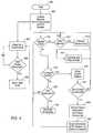
- FIG. 3describes the flow of programming instructions executed in a measurement device.
- FIG. 4describes the flow of programming instructions executed in a remote device that receives data from a measurement device.
- FIG. 1Aprovides a general overview of the invention.
- Remote device 100generally comprises a processor 102 , a memory 103 comprising RAM (random access memory) 104 and ROM (read-only memory) 105 , as well as RF modem 106 .
- remote device 100also comprises a user interface 110 , which in turn comprises a display 112 and input means 114 .
- Remote device 100also comprises a network socket 116 , through which network communications, including wireless communications, may occur.
- remote device 100may be a personal laptop or desktop computer, a handheld computer such as a personal digital assistant or a JavaTM-enabled device, a cellular telephone, or some other computing device such as is known to those skilled in the art.
- Various displays and input means used with such devicesare well known in the art, and may be used in the present invention.
- RF modem 106is used by remote device 100 to effect wireless communications, sometimes through a wireless network 118 , using any one of a number of standards and technologies that are known to those skilled in the art, including but by no means limited to Bluetooth®, EEE 802.11, cellular networks, or any other form of wireless transmission known to those skilled in the art.
- Software instructions loaded into RAM 104 from ROM 105 or some external mediumare executable by processor 102 for configuring and retrieving data from at least one of measurement devices 120 a , 120 b , . . . , 120 n attached to at least one of sensors 122 a , 122 b , . . . , 122 n .
- Remote device 100communicates either directly or through wireless network 118 with measurement devices 120 a , 120 b , . . . , 120 n.
- Sensor 122comprises either a gauge or a transducer.
- Gauges and transducers in equipment, particularly vehiclesare well known to those skilled in the art.
- gauges and/or transducersmay be used to measure vehicle speed, or the pressure or temperature of a vehicle component 123 to which sensor 122 is attached or otherwise proximately located as appropriate.
- Measurement device 120is shown in more detail in FIG. 1B .
- Measurement signal processing device 124enables measurement device 120 to communicate with RF modem 106 via a direct wireless connection or via wireless network 118 .
- measurement signal processing device 124is detachable from and interchangeable with each of measurement devices 120 a , 120 b , . . . , 120 n , whereas in other embodiments measurement signal processing device 124 is a permanent portion of measurement device 120 .
- Measurement signal processing device 124further comprises a measurement processor 126 and a memory 127 comprising a RAM 128 and a ROM 130 .
- Software instructions loaded into RAM 128 from ROM 130are executable by the processor for recording, configuring, and sending information to a remote device 100 .
- component 123can be subjected to diagnostic or analysis tests to assist in isolating problems.
- Remote device 100may comprise a software program for diagnosing the condition of component 123 based on data received from measurement device 120 .
- Measurement device 120 and sensor 122would be placed in the cylinder, and the software program for diagnosing the condition of component 123 would analyze pressure readings received from measurement device 120 to determine whether or not the cylinder's performance fell into an accepted range.
- FIG. 2depicts the structure of a valid data packet 200 that may be used in some embodiments to enable communications between remote device 100 and measurement device 120 .
- Number of bytes field 202indicates the number of bytes of data contained in valid data packet 200 .
- Command number field 204indicates the type of command, i.e., the type of data that is being sent in valid data packet 200 .
- the command numberis one-hundred if valid data packet 200 contains a standard broadcast of information from measurement device 120 , and is two-hundred if valid data packet 200 contains a setup command sent from remote device 100 to measurement device 120 as described below with reference to FIG. 4 .
- Data field 206contains the actual data that is being sent in valid data packet 200 . In some cases this data comprises a setup command, i.e., configuration information, sent by remote device 100 to measurement device 120 . In other cases data field 206 represents the determination by measurement device 120 of a reading taken from sensor 122 . Data field 206 could contain the raw data output by sensor 122 and/or the reading determined by measurement device 24 . Referring to the example given below with reference to Table 1, if sensor 122 was a pressure transducer that had output two volts, measurement device 120 would determine that sensor 122 had provided a reading of eight PSI, and the output of two volts as well as the reading of eight PSI could be included in data field 206 .
- Checksum field 208contains a checksum that is used to validate the integrity of valid data packet 200 , the use of checksums to validate data packets being well known in the art.
- checksum field 208is a twos complement of the sum of the bytes representing command number field 204 and data field 206 .
- FIG. 3describes the function of measurement device 120 .
- measurement device 120is powered up. In some embodiments, this step is initiated when a vehicle engine is started. In other embodiments, one, some, or all of measurement devices 120 a , 120 b , . . . , 120 n may be powered up on receiving a signal from remote device 100 .
- measurement device 120is initialized. As part of this initialization measurement signal processing device 124 is initialized to enable communication with RF modem 106 .
- This stepcomprises measurement device 120 loading configuration information into RAM 128 , either by loading information stored in memory 127 of measurement device 120 , or by receiving configuration instructions from remote device 100 via a setup command.
- Configuration information for measurement device 120comprises the type of measurement for which it is to be configured (e.g., speed, pressure, temperature, etc.).
- Configuration informationgenerally includes at least one scaling function, as discussed below with respect to step 306 .
- Configuration informationalso generally includes an identification of the type of signal that measurement device 120 will be receiving from sensor 122 (e.g., type of digital or analog signal).
- some configuration informationmay be obtained for storage in memory 127 by performing a calibration of measurement device 120 .
- a calibrationmay be performed by capturing outputs from sensor 122 and associating such outputs with a known state of a component 123 .
- a calibrationmight comprise associating a voltage output from sensor 122 with a temperature of component 123 .
- performing a plurality of such calibrationswould enable the creation of a scaling function as is described below with respect to step 306 .
- sensor 122provides input or inputs to measurement device 120 .
- These inputsmay be in any of a number of formats known to those skilled in the art, such as known analog or digital signals.
- sensor 122In embodiments in which sensor 122 is a gauge or transducer in a vehicle, sensor 122 typically provides analog signals in a range of between approximately four and approximately twenty milliamps or zero to approximately five volts.
- measurement processor 126executing software instructions contained in memory 127 , formats the data input by sensor 122 for transmission to remote device 100 .
- This formattingmay comprise a number of different steps. If the data input by sensor 122 is in analog or some other format, measurement processor 126 converts the data to digital format using analog to digital or other conversion methods that are well known to those skilled in the art. Also in step 306 , any required scaling function is applied to the data. The scaling function converts the raw output of sensor 122 to appropriately scaled measurement units representing a measurement read from sensor 122 .
- the particular scaling function applied by measurement processor 126will depend on the kind of sensor 122 whose output is being read; that is, as will be understood by those skilled in the art, different scaling functions will be appropriate for different kinds of gauges and/or transducers. Often, but by no means always, the scaling function will be linear.
- sensor 122is a pressure transducer capable of providing output in a range from zero to five volts, representing pressure readings in a range from zero to twenty PSI (pounds per square inch).
- Table 1 belowrepresents the scaling function used in this case by measurement device 120 to determine the pressure reading provided by sensor 122 based on the voltage output from sensor 122 .
- Measurement processor 126may be programmed to apply the scaling function to data output from sensor 122 .
- measurement processor 126could be programmed to use a table such as Table 1 above to interpolate values for a measurement reading such as the pressure reading. For example, if sensor 122 output 2.25 volts, measurement processor 126 would determine that 2 is the closest number to 2.25 in the sensor output column of Table 1, and that therefore the reported pressure reading P is equal to a number bearing the same ratio to 8 as 2.25 bears to 2, i.e., the reading reported by measurement device 120 is 9 PSI.
- step 308the data input from sensor 122 , having been converted to digital format and otherwise formatted, is stored into the memory of measurement device 120 as a structured packet array.
- Structured packetsare well known, and those skilled in the art will recognize that a number of different structured packet formats could be used in the context of the present invention. Some steps below are discussed with reference to valid data packet 200 , which is used in some embodiments.
- step 310measurement signal processing device 124 sends the data packet or packets created in step 308 to RF modem 106 .
- step 312measurement processor 126 checks command field 204 of valid data packet 200 to see if a valid setup command has been received from remote device 10 . If no setup command has been received, or if the received command was invalid, control returns to step 304 . If a valid setup command has been received, control proceeds to step 314 .
- step 314the process parses the setup command and stores setup data contained in data field 206 in memory 127 .
- the setup commandgenerally will contain information identifying the kind of sensor 122 to which measurement device 120 is connected and the type of signal (e.g., analog or digital) that sensor 122 will provide as input.
- setup datacould be encoded into data field 206 in a variety of different ways.
- data field 206could comprise two bytes, wherein the first byte contains a code indicating the kind of sensor 122 to which measurement device 120 is connected and the second byte indicates the type of signal (e.g., analog or digital) that sensor 122 will output to measurement device 120 .
- other datasuch as a scaling function, could be included in data field 206 .
- controlreturns to step 302 .
- the process described with reference to FIG. 3is terminated when measurement device 120 is powered off. This may occur when measurement device 120 receives an instruction from remote device 100 to power off, or it may occur when, for example, a vehicle engine is powered off.
- step 400a software application running on remote device 100 is initiated.
- step 402network socket connection 116 in remote device 100 , connecting to RF Modem 106 , is initialized.
- preprogrammed configuration informationsuch as the configuration information described above with respect to step 302 , is sent to at least one of measurement devices 120 a , 120 b , . . . , 120 n .
- Controlthen proceeds simultaneously to steps 404 and 410 .
- Steps 404 - 408 and 410 - 428respectively run as first and second parallel processes until the software application is terminated as described below with reference to step 430 .
- the first parallel processbegins in step 404 , in which the process listens for data from measurement device 120 .
- controlproceeds to step 406 , wherein the process determines whether valid data packet 200 has been received, i.e., whether the received data conforms to the format of valid data packet 200 .
- checksum field 208is used to validate received data as described above. If the received data is not in the format of valid data packet 200 , control returns to step 404 . If the received data is valid data packet 200 , control proceeds to step 408 .
- valid data packet 200is stored in RAM 104 of remote device 100 .
- valid data packet 200when stored in RAM 104 , is associated with a time stamp, i.e., the time at which valid data packet 200 was received from measurement device 120 .
- the time stampcan be used, in certain embodiments that allow the user to graph the data received from measurement device 120 , to provide values for the axis of a graph. It will be understood that, once data received from measurement device 120 is stored in RAM 104 , in some embodiments such data may be stored on a computer readable medium or transferred to other computing devices through means that are well known in the art.
- data received from measurement device 120persists in RAM 104 only so long as remote device 100 is communicating with measurement device 120 and/or so long as the processes described with reference to FIG. 4 are running.
- control of the first parallel processreturns to step 404 .
- the second parallel processbegins in step 410 , in which the process determines whether a user input requesting the display of information relating to at least one of measurement devices 120 a , 120 b , . . . , 120 n has been received. If no, control proceeds to step 418 . If yes, control proceeds to step 412 .
- step 412the process determines whether any data from at least one of measurement devices 120 a , 120 b , . . . , 120 n has been stored in RAM 104 as described above with respect to step 408 . If no, control returns to step 410 . If yes, control process to step 414 . In step 414 , the proceeds to retrieve data stored in RAM 104 .
- step 416the data is organized for display and displayed on display 112 .
- valid data packet 200 received in step 406is parsed, using any of the techniques for parsing data packets that are well known to those skilled in the art, for information comprising readings received from measurement device 120 that are contained in data field 206 as described above.
- Datamay then be presented to the user organized in a number of different ways that will be apparent to those skilled in the art. In most embodiments, data is organized according to which of components 123 a , 123 b , . . . , 123 n to which it is related.
- data from one or more of measurement devices 120 a , 120 b , . . . , 120 ncan be graphed over time; such data could also be displayed sorted by time stamps.
- Step 416is repeated for each valid data packet 200 that has been received, or for each valid data packet 200 that has been received since the last time step 416 was visited, if step 416 has been previously executed. Control of the second parallel process then returns to step 410 .
- step 418if a request to display data has not been received in step 410 , the process determines whether a user input has been received requesting a configuration of at least one of measurement devices 120 a , 120 b , . . . , 120 n . If no, control proceeds to step 428 . If yes, control proceeds to step 420 .
- step 420options for configuring measurement devices 120 a , 120 b , 120 n are displayed to the user on display 112 .
- Configuring a measurement devicegenerally comprises providing a measurement device with a scaling function.
- the useris prompted to enter values into a sensor table following the format of Table 1 above.
- Values in a first column of the sensor tabledefine possible values for output from sensor 122 .
- Values in a second column of the sensor tabledefine the readings that correspond to possible output values for sensor 122 .
- an output value from sensor 122 of two voltscorresponds to a pressure reading of eight PSI.
- step 422the process determines whether it has been instructed to send setup commands to at least one of measurement devices 120 a , 120 b , . . . , 120 n . If no, control returns to step 410 . If yes, control proceeds to step 424 .
- step 424the process formats the selected setup options into defined setup commands. In some embodiments, this means that command field 204 has a value of two-hundred.
- data field 206will contain an identifier for measurement device 120 . Also in some embodiments, data field 206 will contain a sensor table created in step 420 above and/or a scaling function.
- step 426the commands formatted in step 424 are sent to RF Modem 106 via network socket connection 116 .
- RF Modem 106in turn transmits the formatted setup commands to one, some, or all of measurement signal processing devices 124 a , 124 b , . . . , 124 n as appropriate. Control of the second parallel process then returns to step 410 .
- step 428the process determines whether input has been received from the user requesting to exit the application. If no, control returns to step 410 . If yes, the application, including both the first parallel process running as described with reference to steps 404 - 408 as well as the second parallel process running as described with reference to steps 410 - 430 , is terminated in step 430 .
Landscapes
- Physics & Mathematics (AREA)
- General Physics & Mathematics (AREA)
- Engineering & Computer Science (AREA)
- Computer Networks & Wireless Communication (AREA)
- Arrangements For Transmission Of Measured Signals (AREA)
Abstract
Description
| TABLE 1 | |||
| Sensor output (volts) | Pressure reading (PSI) | ||
| 0 | 0 | ||
| 1 | 4 | ||
| 2 | 8 | ||
| 3 | 12 | ||
| 4 | 16 | ||
| 5 | 20 | ||
It should be apparent that, in this example, the scaling function can be represented by the equation P=4v, where P represents the pressure reading of sensor122 in PSI determined by
Claims (29)
Priority Applications (7)
| Application Number | Priority Date | Filing Date | Title |
|---|---|---|---|
| US10/780,087US7937080B2 (en) | 2004-02-17 | 2004-02-17 | Wireless measurement device |
| AU2005200530AAU2005200530A1 (en) | 2004-02-17 | 2005-02-08 | Wireless measurement device |
| MXPA05001802AMXPA05001802A (en) | 2004-02-17 | 2005-02-15 | Wireless measurement device. |
| CA002497092ACA2497092A1 (en) | 2004-02-17 | 2005-02-15 | Wireless measurement device |
| CN200510054196.3ACN1658248A (en) | 2004-02-17 | 2005-02-17 | Wireless measurement device |
| GB0503254AGB2411241B (en) | 2004-02-17 | 2005-02-17 | Wireless measurement device |
| AU2010238571AAU2010238571B2 (en) | 2004-02-17 | 2010-11-01 | Wireless measurement device |
Applications Claiming Priority (1)
| Application Number | Priority Date | Filing Date | Title |
|---|---|---|---|
| US10/780,087US7937080B2 (en) | 2004-02-17 | 2004-02-17 | Wireless measurement device |
Publications (2)
| Publication Number | Publication Date |
|---|---|
| US20050181781A1 US20050181781A1 (en) | 2005-08-18 |
| US7937080B2true US7937080B2 (en) | 2011-05-03 |
Family
ID=34394607
Family Applications (1)
| Application Number | Title | Priority Date | Filing Date |
|---|---|---|---|
| US10/780,087Expired - Fee RelatedUS7937080B2 (en) | 2004-02-17 | 2004-02-17 | Wireless measurement device |
Country Status (6)
| Country | Link |
|---|---|
| US (1) | US7937080B2 (en) |
| CN (1) | CN1658248A (en) |
| AU (2) | AU2005200530A1 (en) |
| CA (1) | CA2497092A1 (en) |
| GB (1) | GB2411241B (en) |
| MX (1) | MXPA05001802A (en) |
Families Citing this family (5)
| Publication number | Priority date | Publication date | Assignee | Title |
|---|---|---|---|---|
| US7868780B2 (en)* | 2005-09-20 | 2011-01-11 | Jds Uniphase Corporation | System and method for test probe management |
| US7898430B2 (en)* | 2005-09-20 | 2011-03-01 | Jds Uniphase Corporation | System and method for opportunistic transmission of test probe metadata |
| US8762076B2 (en)* | 2005-09-20 | 2014-06-24 | Jds Uniphase Corporation | System and method for selective distribution of measurement device configuration in a loosely coupled autonomous system |
| EP2661831A2 (en)* | 2011-02-11 | 2013-11-13 | Huawei Technologies Co., Ltd. | Path computation element system and method of routing and wavelength assignment in a wavelength switched optical network |
| CN102506940B (en)* | 2011-11-17 | 2013-11-20 | 中国矿业大学 | Comprehensive detection device and method of coal mine fire area environment by introducing GPS signal |
Citations (32)
| Publication number | Priority date | Publication date | Assignee | Title |
|---|---|---|---|---|
| US5400018A (en)* | 1992-12-22 | 1995-03-21 | Caterpillar Inc. | Method of relaying information relating to the status of a vehicle |
| US5442553A (en)* | 1992-11-16 | 1995-08-15 | Motorola | Wireless motor vehicle diagnostic and software upgrade system |
| US5631832A (en) | 1984-04-27 | 1997-05-20 | Hagenbuch; Leroy G. | Apparatus and method responsive to the on-board measuring of haulage parameters of a vehicle |
| US5732074A (en) | 1996-01-16 | 1998-03-24 | Cellport Labs, Inc. | Mobile portable wireless communication system |
| US5758300A (en)* | 1994-06-24 | 1998-05-26 | Fuji Jukogyo Kabushiki Kaisha | Diagnosis system for motor vehicles and the method thereof |
| US5783990A (en)* | 1996-02-28 | 1998-07-21 | Robert Bosch Gmbh | Method of detecting and documenting exhaust-gas relevant malfunctions of a vehicle having an internal combustion engine utilizing onboard means |
| GB2343253A (en) | 1998-08-04 | 2000-05-03 | Csi Technology Inc | Hand-held wireless collection of machine data |
| US6141610A (en)* | 1998-09-08 | 2000-10-31 | Trimble Navigation Limited | Automated vehicle monitoring system |
| US6263268B1 (en) | 1997-08-26 | 2001-07-17 | Transcontech Corporation | System and method for providing mobile automotive telemetry |
| US6266527B1 (en)* | 1998-04-28 | 2001-07-24 | Ericsson Inc. | System and method for measuring power and bit error rate on the up-link and down-link simultaneously |
| US6295492B1 (en) | 1999-01-27 | 2001-09-25 | Infomove.Com, Inc. | System for transmitting and displaying multiple, motor vehicle information |
| US6308065B1 (en)* | 1998-12-07 | 2001-10-23 | Agilent Technologies, Inc. | Apparatus for testing cellular base stations |
| GB2364126A (en) | 2000-06-26 | 2002-01-16 | Palmer Environmental Ltd | Leak detection apparatus and method |
| US20020049077A1 (en)* | 2000-09-26 | 2002-04-25 | Gero Baese | Weather station |
| US20020119769A1 (en)* | 1998-03-09 | 2002-08-29 | Pekka Heinonen | System for performing environmental measurements and for transferring measurement results |
| US20020133273A1 (en) | 2001-03-14 | 2002-09-19 | Lowrey Larkin Hill | Internet-based vehicle-diagnostic system |
| US20020155816A1 (en)* | 2001-02-27 | 2002-10-24 | Kevin Fodor | Systems and methods for measuring data quality in wireless communication networks |
| US6604033B1 (en) | 2000-07-25 | 2003-08-05 | Networkcar.Com | Wireless diagnostic system for characterizing a vehicle's exhaust emissions |
| US20030162539A1 (en)* | 2002-02-28 | 2003-08-28 | Fiut Brian D. | System and method for remote monitoring of basestations |
| US20030171111A1 (en) | 2002-01-29 | 2003-09-11 | Tim Clark | Cellular telephone interface apparatus and methods |
| GB2386952A (en) | 2002-03-27 | 2003-10-01 | Mitutoyo Corp | Tyre pressure gauge and measuring system having wireless data transmission |
| WO2003085617A1 (en) | 2002-04-02 | 2003-10-16 | Digital Angel Corporation | Method and apparatus for sensing and transmitting a body characteristic of a host |
| US6636790B1 (en) | 2000-07-25 | 2003-10-21 | Reynolds And Reynolds Holdings, Inc. | Wireless diagnostic system and method for monitoring vehicles |
| GB2388197A (en) | 2002-03-01 | 2003-11-05 | Lear Corp | Tire pressure monitor |
| CN2599560Y (en) | 2003-01-30 | 2004-01-14 | 聂建伟 | Motor-driven braking property detector |
| CN1468755A (en) | 2002-06-03 | 2004-01-21 | ŷķ����ʽ���� | Monitoring system, method for remoto-controlling sensing equipment and monitor remoto controller |
| US6819924B1 (en)* | 1999-05-25 | 2004-11-16 | National Semiconductor Corporation | Universal quality measurement system for multimedia and other signals |
| US20050079880A1 (en)* | 2003-10-14 | 2005-04-14 | Donner Peter J. | Wireless sensor alerts |
| GB2410554A (en) | 2004-01-28 | 2005-08-03 | Expert Monitoring Ltd | Configuration of remote sensors in a wireless sensor monitoring system |
| US6941202B2 (en)* | 2001-06-29 | 2005-09-06 | Battelle Memorial Institute | Diagnostics/prognostics using wireless links |
| US20050221817A1 (en)* | 1999-06-04 | 2005-10-06 | Nokia Corporation | Testing device and software |
| US20060079208A1 (en)* | 2004-10-08 | 2006-04-13 | Jeong Kim | Mobile telephone network-based system for detection and location of hazardous agents |
- 2004
- 2004-02-17USUS10/780,087patent/US7937080B2/ennot_activeExpired - Fee Related
- 2005
- 2005-02-08AUAU2005200530Apatent/AU2005200530A1/ennot_activeAbandoned
- 2005-02-15MXMXPA05001802Apatent/MXPA05001802A/enactiveIP Right Grant
- 2005-02-15CACA002497092Apatent/CA2497092A1/ennot_activeAbandoned
- 2005-02-17GBGB0503254Apatent/GB2411241B/ennot_activeExpired - Fee Related
- 2005-02-17CNCN200510054196.3Apatent/CN1658248A/enactivePending
- 2010
- 2010-11-01AUAU2010238571Apatent/AU2010238571B2/ennot_activeCeased
Patent Citations (36)
| Publication number | Priority date | Publication date | Assignee | Title |
|---|---|---|---|---|
| US5631832A (en) | 1984-04-27 | 1997-05-20 | Hagenbuch; Leroy G. | Apparatus and method responsive to the on-board measuring of haulage parameters of a vehicle |
| US5442553A (en)* | 1992-11-16 | 1995-08-15 | Motorola | Wireless motor vehicle diagnostic and software upgrade system |
| US5400018A (en)* | 1992-12-22 | 1995-03-21 | Caterpillar Inc. | Method of relaying information relating to the status of a vehicle |
| US5758300A (en)* | 1994-06-24 | 1998-05-26 | Fuji Jukogyo Kabushiki Kaisha | Diagnosis system for motor vehicles and the method thereof |
| US5732074A (en) | 1996-01-16 | 1998-03-24 | Cellport Labs, Inc. | Mobile portable wireless communication system |
| EP1515496A2 (en) | 1996-01-16 | 2005-03-16 | Cellport Labs. Inc. | Mobile portable wireless communication system |
| US5783990A (en)* | 1996-02-28 | 1998-07-21 | Robert Bosch Gmbh | Method of detecting and documenting exhaust-gas relevant malfunctions of a vehicle having an internal combustion engine utilizing onboard means |
| US6263268B1 (en) | 1997-08-26 | 2001-07-17 | Transcontech Corporation | System and method for providing mobile automotive telemetry |
| US20020119769A1 (en)* | 1998-03-09 | 2002-08-29 | Pekka Heinonen | System for performing environmental measurements and for transferring measurement results |
| US6266527B1 (en)* | 1998-04-28 | 2001-07-24 | Ericsson Inc. | System and method for measuring power and bit error rate on the up-link and down-link simultaneously |
| GB2343253A (en) | 1998-08-04 | 2000-05-03 | Csi Technology Inc | Hand-held wireless collection of machine data |
| US6141610A (en)* | 1998-09-08 | 2000-10-31 | Trimble Navigation Limited | Automated vehicle monitoring system |
| US6308065B1 (en)* | 1998-12-07 | 2001-10-23 | Agilent Technologies, Inc. | Apparatus for testing cellular base stations |
| US6295492B1 (en) | 1999-01-27 | 2001-09-25 | Infomove.Com, Inc. | System for transmitting and displaying multiple, motor vehicle information |
| US6819924B1 (en)* | 1999-05-25 | 2004-11-16 | National Semiconductor Corporation | Universal quality measurement system for multimedia and other signals |
| US20050221817A1 (en)* | 1999-06-04 | 2005-10-06 | Nokia Corporation | Testing device and software |
| GB2364126A (en) | 2000-06-26 | 2002-01-16 | Palmer Environmental Ltd | Leak detection apparatus and method |
| US6636790B1 (en) | 2000-07-25 | 2003-10-21 | Reynolds And Reynolds Holdings, Inc. | Wireless diagnostic system and method for monitoring vehicles |
| US6604033B1 (en) | 2000-07-25 | 2003-08-05 | Networkcar.Com | Wireless diagnostic system for characterizing a vehicle's exhaust emissions |
| US20020049077A1 (en)* | 2000-09-26 | 2002-04-25 | Gero Baese | Weather station |
| US20020155816A1 (en)* | 2001-02-27 | 2002-10-24 | Kevin Fodor | Systems and methods for measuring data quality in wireless communication networks |
| US20020133273A1 (en) | 2001-03-14 | 2002-09-19 | Lowrey Larkin Hill | Internet-based vehicle-diagnostic system |
| US6611740B2 (en) | 2001-03-14 | 2003-08-26 | Networkcar | Internet-based vehicle-diagnostic system |
| US6941202B2 (en)* | 2001-06-29 | 2005-09-06 | Battelle Memorial Institute | Diagnostics/prognostics using wireless links |
| US20030171111A1 (en) | 2002-01-29 | 2003-09-11 | Tim Clark | Cellular telephone interface apparatus and methods |
| US20030162539A1 (en)* | 2002-02-28 | 2003-08-28 | Fiut Brian D. | System and method for remote monitoring of basestations |
| GB2388197A (en) | 2002-03-01 | 2003-11-05 | Lear Corp | Tire pressure monitor |
| GB2386952A (en) | 2002-03-27 | 2003-10-01 | Mitutoyo Corp | Tyre pressure gauge and measuring system having wireless data transmission |
| WO2003085617A1 (en) | 2002-04-02 | 2003-10-16 | Digital Angel Corporation | Method and apparatus for sensing and transmitting a body characteristic of a host |
| CN1468755A (en) | 2002-06-03 | 2004-01-21 | ŷķ����ʽ���� | Monitoring system, method for remoto-controlling sensing equipment and monitor remoto controller |
| US6950020B2 (en)* | 2002-06-03 | 2005-09-27 | Omron Corporation | Surveillance system, method of remotely controlling sensor apparatus, and surveillance remote controller |
| CN2599560Y (en) | 2003-01-30 | 2004-01-14 | 聂建伟 | Motor-driven braking property detector |
| US20050079880A1 (en)* | 2003-10-14 | 2005-04-14 | Donner Peter J. | Wireless sensor alerts |
| WO2005073671A1 (en) | 2004-01-28 | 2005-08-11 | Expert Monitoring Limited | Wireless sensor monitoring systems |
| GB2410554A (en) | 2004-01-28 | 2005-08-03 | Expert Monitoring Ltd | Configuration of remote sensors in a wireless sensor monitoring system |
| US20060079208A1 (en)* | 2004-10-08 | 2006-04-13 | Jeong Kim | Mobile telephone network-based system for detection and location of hazardous agents |
Non-Patent Citations (2)
| Title |
|---|
| Examination Report dated Jan. 9, 2007 (4 pages). |
| International Search Report dated Jun. 8, 2005 (2 pages). |
Also Published As
| Publication number | Publication date |
|---|---|
| GB2411241A (en) | 2005-08-24 |
| GB0503254D0 (en) | 2005-03-23 |
| GB2411241B (en) | 2007-08-08 |
| MXPA05001802A (en) | 2005-08-19 |
| CA2497092A1 (en) | 2005-08-17 |
| AU2010238571B2 (en) | 2011-09-22 |
| AU2010238571A1 (en) | 2010-11-18 |
| US20050181781A1 (en) | 2005-08-18 |
| CN1658248A (en) | 2005-08-24 |
| AU2005200530A1 (en) | 2005-09-01 |
Similar Documents
| Publication | Publication Date | Title |
|---|---|---|
| AU2010238571B2 (en) | Wireless measurement device | |
| US8180515B2 (en) | Cellular phone configured with off-board device capabilities and starter/charger and battery testing capabilities | |
| US8738329B2 (en) | Calibration method/system and verification method for digital torque tools | |
| US12158371B2 (en) | Calibration precision enhancement method for digital scale | |
| EP0949506A3 (en) | Method and apparatus for data management authentication in a clinical analyzer | |
| Wobschall | Networked sensor monitoring using the universal IEEE 1451 standard | |
| US7630801B2 (en) | System and method for retrieving and displaying vehicle control unit data | |
| KR20050002890A (en) | System for collecting operation data of work machine | |
| US20040002349A1 (en) | Mobile telephone with environment sensor | |
| US12139080B2 (en) | Apparatus for diagnostics communication error of vehicle, system having the same, and method thereof | |
| JP4093392B2 (en) | Self-supporting network measurement system | |
| KR20220054985A (en) | Management system for experiment equipment | |
| US7802143B2 (en) | Testing system and testing method thereof | |
| US8333876B2 (en) | Ion concentration measurement system and methods thereof | |
| US9454510B2 (en) | Measuring device, a calibration device, a measuring system and a method with a dynamic data sheet | |
| JPH07160556A (en) | Data format converting device | |
| AU764753B2 (en) | Weight simulation calibration rig and method | |
| JP2006232032A (en) | Sensor information transmitting/receiving system, and sensor information transmitting/receiving method | |
| FI110286B (en) | Method and apparatus for processing weighing results | |
| KR100262609B1 (en) | Apparatus and method for monitoring data in automobiles | |
| KR20020073833A (en) | A multi-channel measuring instrument of a temperature and a humidity for value a hot and heat's optimum | |
| CN119643105A (en) | Screen testing method, system, industrial computer and storage medium | |
| CN116431078A (en) | Information acquisition method, device, equipment and storage medium | |
| SE0201429D0 (en) | Method and device for volume meter diagnostics | |
| CN118535395A (en) | Verification method and system for flash memory control chip |
Legal Events
| Date | Code | Title | Description |
|---|---|---|---|
| AS | Assignment | Owner name:EATON CORPORATION (HG), OHIO Free format text:ASSIGNMENT OF ASSIGNORS INTEREST;ASSIGNORS:STARKS, MATTHEW W.;MELVIN, STEVEN L.;SNOW, KEVIN D.;REEL/FRAME:015004/0539 Effective date:20040212 | |
| AS | Assignment | Owner name:EATON CORPORATION, OHIO Free format text:ASSIGNMENT OF ASSIGNORS INTEREST;ASSIGNORS:STARKS, MATTHEW W.;MELVIN, STEVEN L.;SNOW, KEVIN D.;REEL/FRAME:015888/0754 Effective date:20040212 | |
| STCF | Information on status: patent grant | Free format text:PATENTED CASE | |
| FPAY | Fee payment | Year of fee payment:4 | |
| FEPP | Fee payment procedure | Free format text:MAINTENANCE FEE REMINDER MAILED (ORIGINAL EVENT CODE: REM.); ENTITY STATUS OF PATENT OWNER: LARGE ENTITY | |
| AS | Assignment | Owner name:EATON INTELLIGENT POWER LIMITED, IRELAND Free format text:ASSIGNMENT OF ASSIGNORS INTEREST;ASSIGNOR:EATON CORPORATION;REEL/FRAME:048855/0626 Effective date:20171231 | |
| LAPS | Lapse for failure to pay maintenance fees | Free format text:PATENT EXPIRED FOR FAILURE TO PAY MAINTENANCE FEES (ORIGINAL EVENT CODE: EXP.); ENTITY STATUS OF PATENT OWNER: LARGE ENTITY | |
| STCH | Information on status: patent discontinuation | Free format text:PATENT EXPIRED DUE TO NONPAYMENT OF MAINTENANCE FEES UNDER 37 CFR 1.362 | |
| FP | Lapsed due to failure to pay maintenance fee | Effective date:20190503 |