US7936160B1 - Apparatus and method for valley emulated current mode control - Google Patents
Apparatus and method for valley emulated current mode controlDownload PDFInfo
- Publication number
- US7936160B1 US7936160B1US11/740,236US74023607AUS7936160B1US 7936160 B1US7936160 B1US 7936160B1US 74023607 AUS74023607 AUS 74023607AUS 7936160 B1US7936160 B1US 7936160B1
- Authority
- US
- United States
- Prior art keywords
- current
- inductor
- voltage
- mode switching
- capacitor
- Prior art date
- Legal status (The legal status is an assumption and is not a legal conclusion. Google has not performed a legal analysis and makes no representation as to the accuracy of the status listed.)
- Active, expires
Links
Images


Classifications
- H—ELECTRICITY
- H02—GENERATION; CONVERSION OR DISTRIBUTION OF ELECTRIC POWER
- H02M—APPARATUS FOR CONVERSION BETWEEN AC AND AC, BETWEEN AC AND DC, OR BETWEEN DC AND DC, AND FOR USE WITH MAINS OR SIMILAR POWER SUPPLY SYSTEMS; CONVERSION OF DC OR AC INPUT POWER INTO SURGE OUTPUT POWER; CONTROL OR REGULATION THEREOF
- H02M3/00—Conversion of DC power input into DC power output
- H02M3/02—Conversion of DC power input into DC power output without intermediate conversion into AC
- H02M3/04—Conversion of DC power input into DC power output without intermediate conversion into AC by static converters
- H02M3/10—Conversion of DC power input into DC power output without intermediate conversion into AC by static converters using discharge tubes with control electrode or semiconductor devices with control electrode
- H02M3/145—Conversion of DC power input into DC power output without intermediate conversion into AC by static converters using discharge tubes with control electrode or semiconductor devices with control electrode using devices of a triode or transistor type requiring continuous application of a control signal
- H02M3/155—Conversion of DC power input into DC power output without intermediate conversion into AC by static converters using discharge tubes with control electrode or semiconductor devices with control electrode using devices of a triode or transistor type requiring continuous application of a control signal using semiconductor devices only
- H02M3/156—Conversion of DC power input into DC power output without intermediate conversion into AC by static converters using discharge tubes with control electrode or semiconductor devices with control electrode using devices of a triode or transistor type requiring continuous application of a control signal using semiconductor devices only with automatic control of output voltage or current, e.g. switching regulators
Definitions
- the inventionis related to voltage regulation, and in particular, to an apparatus and method for valley emulated current mode control for a switching regulator.
- a switching regulatormay be configured to provide an output voltage (Vout) in response to an input voltage (Vin).
- a switching regulatorincludes an inductor that is coupled to a switch.
- the inductor currentis a triangle wave current based on the opening and closing of the switch, and an output capacitor provides Vout from the inductor current.
- the switchis controlled by a control signal, where the duty cycle or the frequency of the control signal is typically modulated based on negative feedback.
- a diode-rectified switching regulatoremploys a diode to rectify the inductor current.
- a synchronous switching regulatoremploys a synchronous switch rather than a diode.
- the inductor currentcan be positive or negative.
- other topologiesmay be employed, such as a SEPIC topology or a CUK topology.
- FIG. 1illustrates a block diagram of an embodiment of a regulator circuit
- FIG. 2shows a block diagram of an embodiment of the regulator circuit of FIG. 1 in which a boost topology is employed
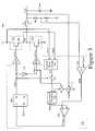
- FIG. 3illustrates a block diagram of an embodiment of the regulator circuit of FIG. 1 ;
- FIGS. 4A-4Bshow timing diagrams of peak current mode control and valley current mode control respectively
- FIG. 5illustrates a block diagram of an embodiment of the regulator controller of FIG. 3 ;
- FIG. 6shows a block diagram of an embodiment of the regulator controller of FIG. 5 ;
- FIG. 7illustrates an embodiment of the regulator controller of FIG. 6 , arranged in accordance with aspects of the invention.
- the inventionis related to a valley current mode switching regulator.
- the main switch of the switching regulatorWhen the main switch of the switching regulator is closed, the current through the main switch is sensed and sampled. The sensed main switch current is held while the main switch is off. While the main switch is off, the inductor current is emulated. Emulated valley current mode control is provided based on the sensed main switch current and the emulated flywheel current.
- FIG. 1illustrates a block diagram of an embodiment of regulator circuit 100 .
- Regulator circuit 100includes main switch 110 , synchronous switch 111 , inductor L 1 , output capacitor Cout, drivers DR 1 and DR 2 , and regulator controller 101 .
- Regulator controller 101includes current sense circuit 120 , switch S 1 , capacitor C 1 , and switch control circuitry 130 .
- inductor L 1provides current I L . More specifically, in a buck regulator topology embodiment, inductor circuit L 1 is arranged such that a voltage substantially given by Vin ⁇ Vout is across inductor L 1 when switch 110 is closed. Accordingly, in a buck regulator topology embodiment, dI L /dt is substantially given by (Vin ⁇ Vout)/L 1 when switch 110 is closed. In a buck regulator topology embodiment, when switch 110 is open, a voltage substantially given by—Vout is across L 1 , so that dI L /dt is substantially given by—Vout/L 1 .
- capacitor Coutis an output capacitor for regulator circuit 100 .
- Current-sense circuit 120is configured to sense a current across main switch circuit 110 and provide current sense signal CS in response to the sensed current.
- switch S 1 and capacitor C 1are arranged to operate together as a sample-and-hold circuit to sample signal CS when main switch 110 is closed, and to hold signal CS when main switch 110 is open, to provide signal Vsh.
- Switch control circuitry 130is arranged to provide driver input signal DRIN 1 and driver input signal DRIN 2 based, in part, on signal Vsh and output voltage Vout. Further, switch control circuitry 130 is configured to provide signal DRIN 2 as a logical inverse of signal DRIN 1 .
- switch control circuitry 130may control different switching regulation topologies, including buck regulation, boost regulation, buck-boost regulation, inverting regulation, or the like.
- Driver DR 1is arranged to provide switch control signal SCTL 1 from driver input signal DRIN 1
- driver DR 2is arranged to provide switch control signal SCTL 2 from driver input signal DRIN 1 .
- switch 110is configured to open and close responsive to signal SCTL 1
- synchronous switch 111is configured to open and close responsive to signal SCTL 2 .
- FIG. 1illustrates a step-down (buck) switching regulator topology
- the inventionis not so limited.
- Embodiments of the inventionmay be used in virtually any valley current mode switching regulator topology, including a boost topology, an inverting topology, a buck-boost topology, or the like.
- Embodiments of the inventionmay also include transformer isolated versions of the various topologies, and may include various combinations of ac or dc voltage or current as input, output, or controlled quantities.
- FIG. 2illustrates an embodiment of a regulator circuit 200 , which is an embodiment of regulator circuit 100 in a boost topology.
- the main switchis a top-side switch and the synchronous switch is a bottom-side switch.
- the main switchis a bottom-side switch and the synchronous switch is a top-side switch.
- FIG. 3illustrates an embodiment of regulator circuit 300 , which may be employed as an embodiment of regulator circuit 100 of FIG. 1 .
- Regulator circuit 300further includes resistors R 1 and R 2 .
- main switch 310includes transistor M 0 .
- Synchronous switch 311includes transistor M 1 .
- Switch control circuitry 330includes SR latch SR 1 , inverter 370 , PWM comparator 340 , error amp A 1 , current source I 1 , and summing junction 350 .
- Summing junction 350includes capacitor C 1 (not shown in FIG. 3 ) to which signals are provided at the summing junction.
- regulator circuit 300provides power regulation with valley current mode control.
- the main switche.g. transistor M 0
- the synchronous switche.g. transistor M 1
- V RAMPthe slope of voltage V RAMP (where V RAMP is the voltage associated with signal RAMP) while transistor M 1 is conducting
- V RAMP /T⁇ Vout*Ri/L 1
- Rithe current sense gain (i.e. the ratio the current sense voltage CS to the current across transistor M 0 )
- Tthe period of signal CLK.
- Resistors R 1 and R 2may be arranged as a voltage divider that is configured to provide voltage Vfb from voltage Vout. Additionally, error amplifier A 1 may be configured to provide error signal ERR from signals Vfb and Vref 1 PWM comparator circuit 340 is configured to provide comparator output signal Comp_out in response to a comparison of signals ERR and Ramp. In one embodiment, SR latch SR 1 is arranged to provide driver input signal DRIN 1 responsive to comparator output signal Comp_out and clock signal CLK. Clock signal CLK may be provided by a clock generator (not shown). Driver DR 1 may be configured to provide main switch control signal SCTL 1 from signal DRIN 1 . Also, inverter 370 may be arranged to providing driver input signal DRIN 2 by inverting signal DRV 1 . Driver DR 2 may be arranged to provide synchronous switch control signal SCTL 2 from signal DRIN 2 .
- regulator circuit 300may include other arrangements of circuit 300 .
- current source circuit I 1may be arranged in a different manner than shown in FIG. 3 .
- FIG. 3illustrates an embodiment in which inverter 370 is employed to provide signal DRIN 2 as an inverse of signal DRIN 1
- inverter 370is employed to provide signal DRIN 2 as an inverse of signal DRIN 1
- other arrangementsmay be employed to provide signal DRIN 2 .
- additionally circuitrysuch as over-voltage protection and the like may be included between the output of SR latch SR 1 and driver DR 1 .
- Regulator circuit 300may include a compensation loop for error amp A 1 .
- a boost topology, a buck-boost topology, inverting topology, or the likemay be employed.
- the components shown in regulator controller 301are included together on an integrated circuit, with the components shown outside regulator controller 301 off-chip. However, in other embodiments, some of the components shown inside regulator controller 301 may be off-chip, and some of the component shown outside regulator controller 301 may be on-chip.
- Each of the resistors describedmay consist of a single resistor only, or may include a plurality of resistors that are coupled in series and/or in parallel, and the like.
- each of the capacitors describedmay consist of a single capacitor only, or may include a plurality of capacitors that are coupled in series and/or in parallel, and the like.
- Each of the inductors describedmay consist of a single inductor only, or may include a plurality of inductors that are coupled in series and/or in parallel, and the like.
- Regulator circuit 300employs valley current mode control, which may be more easily understood with reference to FIG. 4B , discussed below.
- FIGS. 4A-4Bshow timing diagrams of peak current mode control and valley current mode control, respectively.
- inductor current I Lbegins ramping upward at the beginning of each clock cycle. Once inductor current I L reaches a peak current threshold, I PEAK , inductor current I L then begins ramping downward. It continues ramping downward until the beginning of the next clock cycle, where it begins ramping upward again.
- inductor current I Lbegins ramping downward at the beginning of each clock cycle. Once inductor current I L reaches a valley current threshold, I VALLEY , inductor current I L then begins ramping upward. It continues ramping upward until the beginning of the next clock cycle, where it begins ramping downward again.
- FIG. 5illustrates an embodiment of the regulator controller 501 of FIG. 5 , which is an embodiment of valley current mode regulator controller 301 of FIG. 301 .
- Regulator controller 501further includes slope compensation circuit 560 .
- summing junction 550includes another input for slope compensation signal Slope_comp so that signal Slope_comp is added to the signals that are summed at summing junction 550 .
- Slope compensationis used in order to help stabilize gain and prevent sub-harmonic oscillation, by adding an external ramp V SLOPE to the current sense signal.
- Slope compensationessentially compensates for the fact that valley current is being used rather than average current; slope compensation is not needed for average current mode.
- signal Slope_compis a fixed ramp (e.g., the slope of the ramp is constant).
- the rampis proportional to the opposite slope of the inductor. This may cause any tendency toward sub-harmonic oscillation to damp in one switching cycle.
- signal Slope_compmay be a voltage substantially given by (Vin ⁇ Vout)*Ri/L 1 .
- the down-slope of the emulated inductor currentis provided as signal Ramp is Vout*Ri/L 1 .
- this combined rampmay be provided by current source I 1 rather providing a separate slope compensation and a separate emulated down-slope signal and combining them.
- current source I 1rather providing a separate slope compensation and a separate emulated down-slope signal and combining them.
- a ramp having a down-slope of Vin*Ri/Lmay be provided rather than providing separate slope compensation and down-slope emulation signal, as illustrated in FIG. 6 .
- FIG. 6shows an embodiment of the regulator controller 601 , which is similar to regulator controller 501 of FIG. 5 in some ways, albeit different in other ways.
- the slope compensation circuit 560 and current source I 1are replaced by capacitor C 1 and current source 12 , which operate to provide a signal that combines slope compensation and emulated down slope.
- the node at the top of capacitor C 1is a summing junction since current voltage CS and current from current source 12 are both provided to capacitor C 1 .
- current source circuit 12provides current given by Vin/R, as shown in FIG. 6 .
- the down-slope of signal Rampis Vin*Ri/L, which is a combination of the emulated down-slope and the ramp compensation.
- a current given by Vout/Rmay be provided.
- a current given by (Vin+Vout)/Rmay be provided.
- FIG. 6Although one particular embodiment is illustrated in FIG. 6 , other embodiments are within the scope of the spirit of the invention. For example, other embodiments may use a separate sample and hold capacitor, with an additional emulation ramp capacitor, slope compensation capacitor and associated switches, or the functions may be combined by C 1 .
- Signals CS, RAMP and ERRmay be configured or reconfigured in such a manner as to use ground referenced, positive or negative supply voltages, with normal or inverted slopes and polarities to accommodate such.
- FIG. 7illustrates an embodiment of regulator controller 701 , which may be employed as an embodiment of regulator controller 601 of FIG. 6 .
- Current source 12includes resistor R and transistors Q 0 -Q 3 .
Landscapes
- Engineering & Computer Science (AREA)
- Power Engineering (AREA)
- Dc-Dc Converters (AREA)
Abstract
Description
The invention is related to voltage regulation, and in particular, to an apparatus and method for valley emulated current mode control for a switching regulator.
A switching regulator may be configured to provide an output voltage (Vout) in response to an input voltage (Vin). Typically, a switching regulator includes an inductor that is coupled to a switch. In operation, the inductor current is a triangle wave current based on the opening and closing of the switch, and an output capacitor provides Vout from the inductor current. Also, the switch is controlled by a control signal, where the duty cycle or the frequency of the control signal is typically modulated based on negative feedback.
Additionally, a diode-rectified switching regulator employs a diode to rectify the inductor current. A synchronous switching regulator employs a synchronous switch rather than a diode. In a synchronous switching regulator, the inductor current can be positive or negative. Additionally, other topologies may be employed, such as a SEPIC topology or a CUK topology.
Non-limiting and non-exhaustive embodiments of the present invention are described with reference to the following drawings, in which:
Various embodiments of the present invention will be described in detail with reference to the drawings, where like reference numerals represent like parts and assemblies throughout the several views. Reference to various embodiments does not limit the scope of the invention, which is limited only by the scope of the claims attached hereto. Additionally, any examples set forth in this specification are not intended to be limiting and merely set forth some of the many possible embodiments for the claimed invention.
Briefly stated, the invention is related to a valley current mode switching regulator. When the main switch of the switching regulator is closed, the current through the main switch is sensed and sampled. The sensed main switch current is held while the main switch is off. While the main switch is off, the inductor current is emulated. Emulated valley current mode control is provided based on the sensed main switch current and the emulated flywheel current.
In operation, inductor L1 provides current IL. More specifically, in a buck regulator topology embodiment, inductor circuit L1 is arranged such that a voltage substantially given by Vin−Vout is across inductor L1 whenswitch 110 is closed. Accordingly, in a buck regulator topology embodiment, dIL/dt is substantially given by (Vin−Vout)/L1 whenswitch 110 is closed. In a buck regulator topology embodiment, whenswitch 110 is open, a voltage substantially given by—Vout is across L1, so that dIL/dt is substantially given by—Vout/L1.
Also, capacitor Cout is an output capacitor forregulator circuit 100. Current-sense circuit 120 is configured to sense a current acrossmain switch circuit 110 and provide current sense signal CS in response to the sensed current. Additionally, switch S1 and capacitor C1 are arranged to operate together as a sample-and-hold circuit to sample signal CS whenmain switch 110 is closed, and to hold signal CS whenmain switch 110 is open, to provide signal Vsh.Switch control circuitry 130 is arranged to provide driver input signal DRIN1 and driver input signal DRIN2 based, in part, on signal Vsh and output voltage Vout. Further,switch control circuitry 130 is configured to provide signal DRIN2 as a logical inverse of signal DRIN1. In various embodiments,switch control circuitry 130 may control different switching regulation topologies, including buck regulation, boost regulation, buck-boost regulation, inverting regulation, or the like. Driver DR1 is arranged to provide switch control signal SCTL1 from driver input signal DRIN1, and driver DR2 is arranged to provide switch control signal SCTL2 from driver input signal DRIN1. Additionally,switch 110 is configured to open and close responsive to signal SCTL1, andsynchronous switch 111 is configured to open and close responsive to signal SCTL2.
AlthoughFIG. 1 illustrates a step-down (buck) switching regulator topology, the invention is not so limited. Embodiments of the invention may be used in virtually any valley current mode switching regulator topology, including a boost topology, an inverting topology, a buck-boost topology, or the like. Embodiments of the invention may also include transformer isolated versions of the various topologies, and may include various combinations of ac or dc voltage or current as input, output, or controlled quantities.
For example,FIG. 2 illustrates an embodiment of aregulator circuit 200, which is an embodiment ofregulator circuit 100 in a boost topology. Inregulator circuit 100 ofFIG. 1 , the main switch is a top-side switch and the synchronous switch is a bottom-side switch. Conversely, inregulator circuit 200 ofFIG. 2 the main switch is a bottom-side switch and the synchronous switch is a top-side switch.
In operation,regulator circuit 300 provides power regulation with valley current mode control.
While the main switch (e.g. transistor M0) is conducting and the synchronous switch (e.g. transistor M1) is not conducting, switch S1 is closed and switch S2 is open. Accordingly, while the main switch (e.g. transistor M0) is conducting, current sense voltage CS is sampled and used as signal Ramp. In a buck embodiment, signal Ramp ramps upward while the main switch (e.g. transistor M0) is conducting. When the synchronous switch (e.g. transistor M1) stops conducting and transistor M1 starts conducting, switch S1 opens and switch S2 closes. Accordingly, voltage CS is held at summingjunction 350 at the moment switch S1 opens. Current provided by current source I1 is provided to summingjunction 350 to emulate the slope of inductor current ILwhile the synchronous switch (e.g. transistor M1) is conducting.
For the specific embodiment illustrated inFIG. 3 , when transistor M1 is conducting, the slope of inductor current ILis substantially given by—Vout/L1. Accordingly, the slope of voltage VRAMP(where VRAMPis the voltage associated with signal RAMP) while transistor M1 is conducting should be VRAMP/T=−Vout*Ri/L1, where Ri represents the current sense gain (i.e. the ratio the current sense voltage CS to the current across transistor M0) and T is the period of signal CLK. Accordingly, R and C1 should be pre-selected by the designer such that the equation C1=L1/(R*Ri) is substantially satisfied.
This way, when the main switch is closed, the actual inductor current is sensed. The peak value of the inductor current is sampled and held. When the main switch is open, the down-slope of the inductor current is emulated by providing current I1 to capacitor C1 of summingjunction 350.
Current I1 may be provided differently in different topologies. As discussed above, for a buck regulator topology, I1=−Vout/R may be used (e.g. Vout/R with I1 as a sinking current). For a boost regulator topology, (Vin−Vout)/R as sourcing current may be used instead. In other topologies, the current provided may be different from that discussed above by providing a current that is a combination of (1) the current provided to the capacitor to generate an emulated slope, and (2) a slope compensation current (as discussed below with regard toFIG. 6 in one embodiment).
Resistors R1 and R2 may be arranged as a voltage divider that is configured to provide voltage Vfb from voltage Vout. Additionally, error amplifier A1 may be configured to provide error signal ERR from signals Vfb and Vref1PWM comparator circuit 340 is configured to provide comparator output signal Comp_out in response to a comparison of signals ERR and Ramp. In one embodiment, SR latch SR1 is arranged to provide driver input signal DRIN1 responsive to comparator output signal Comp_out and clock signal CLK. Clock signal CLK may be provided by a clock generator (not shown). Driver DR1 may be configured to provide main switch control signal SCTL1 from signal DRIN1. Also,inverter 370 may be arranged to providing driver input signal DRIN2 by inverting signal DRV1. Driver DR2 may be arranged to provide synchronous switch control signal SCTL2 from signal DRIN2.
Although a particulararrangement regulator circuit 300 is illustrated inFIG. 3 , other embodiments may include other arrangements ofcircuit 300. For example, current source circuit I1 may be arranged in a different manner than shown inFIG. 3 . AlthoughFIG. 3 illustrates an embodiment in which inverter370 is employed to provide signal DRIN2 as an inverse of signal DRIN1, in other embodiments, other arrangements may be employed to provide signal DRIN2. Also, additionally circuitry such as over-voltage protection and the like may be included between the output of SR latch SR1 and driver DR1.Regulator circuit 300 may include a compensation loop for error amp A1. As previously discussed, although a buck topology is illustrated inFIG. 3 , in other embodiments, a boost topology, a buck-boost topology, inverting topology, or the like may be employed.
In one embodiment, the components shown inregulator controller 301 are included together on an integrated circuit, with the components shown outsideregulator controller 301 off-chip. However, in other embodiments, some of the components shown insideregulator controller 301 may be off-chip, and some of the component shown outsideregulator controller 301 may be on-chip.
Each of the resistors described may consist of a single resistor only, or may include a plurality of resistors that are coupled in series and/or in parallel, and the like. Similarly, each of the capacitors described may consist of a single capacitor only, or may include a plurality of capacitors that are coupled in series and/or in parallel, and the like. Each of the inductors described may consist of a single inductor only, or may include a plurality of inductors that are coupled in series and/or in parallel, and the like. These and other embodiments are within the spirit and scope of the invention.
There are several different methods of current mode control, including peak, valley, average, and sample-and-hold. Each of these methods sample the DC current, and include an outer voltage loop and an inner current loop. The current loop gain splits the complex conjugate pole of the output LC filter into two real poles, so that the characteristics of the output LC filter are set by the output capacitor and the load resistor.
In peak current mode, as illustrated inFIG. 4A , inductor current ILbegins ramping upward at the beginning of each clock cycle. Once inductor current ILreaches a peak current threshold, IPEAK, inductor current ILthen begins ramping downward. It continues ramping downward until the beginning of the next clock cycle, where it begins ramping upward again.
In valley current mode, as illustrated inFIG. 4B , inductor current ILbegins ramping downward at the beginning of each clock cycle. Once inductor current ILreaches a valley current threshold, IVALLEY, inductor current ILthen begins ramping upward. It continues ramping upward until the beginning of the next clock cycle, where it begins ramping downward again.
Inregulator controller 501, summingjunction 550 includes another input for slope compensation signal Slope_comp so that signal Slope_comp is added to the signals that are summed at summingjunction 550.
Slope compensation is used in order to help stabilize gain and prevent sub-harmonic oscillation, by adding an external ramp VSLOPEto the current sense signal. Slope compensation essentially compensates for the fact that valley current is being used rather than average current; slope compensation is not needed for average current mode.
In one embodiment, signal Slope_comp is a fixed ramp (e.g., the slope of the ramp is constant).
In another embodiment, the ramp is proportional to the opposite slope of the inductor. This may cause any tendency toward sub-harmonic oscillation to damp in one switching cycle. For example, for one buck embodiment, signal Slope_comp may be a voltage substantially given by (Vin−Vout)*Ri/L1. In this example, the down-slope of the emulated inductor current is provided as signal Ramp is Vout*Ri/L1. In this embodiment, when switch S2 is closed, the total slope is [(Vin−Vout)*Ri/L1]+Vout*Ri/L1=Vin*Ri/L.
Accordingly, in another example embodiment, as illustrated inFIG. 6 , this combined ramp may be provided by current source I1 rather providing a separate slope compensation and a separate emulated down-slope signal and combining them. For example, for a buck embodiment, since the combined down-slope is [(Vin−Vout)*Ri/L1]+Vout*Ri/L1=Vin*Ri/L, a ramp having a down-slope of Vin*Ri/L may be provided rather than providing separate slope compensation and down-slope emulation signal, as illustrated inFIG. 6 .
In a buck embodiment,current source circuit 12 provides current given by Vin/R, as shown inFIG. 6 . Accordingly, in this embodiment, the down-slope of signal Ramp is Vin*Ri/L, which is a combination of the emulated down-slope and the ramp compensation.
In a boost embodiment, a current given by Vout/R may be provided. In a buck-boost embodiment, a current given by (Vin+Vout)/R may be provided.
Although one particular embodiment is illustrated inFIG. 6 , other embodiments are within the scope of the spirit of the invention. For example, other embodiments may use a separate sample and hold capacitor, with an additional emulation ramp capacitor, slope compensation capacitor and associated switches, or the functions may be combined by C1.
Signals CS, RAMP and ERR may be configured or reconfigured in such a manner as to use ground referenced, positive or negative supply voltages, with normal or inverted slopes and polarities to accommodate such.
The above specification, examples and data provide a description of the manufacture and use of the composition of the invention. Since many embodiments of the invention can be made without departing from the spirit and scope of the invention, the invention also resides in the claims hereinafter appended.
Claims (17)
1. A circuit for current mode switching regulation, comprising:
a valley current mode switching regulator controller that is arranged to provide a first switch control signal to a main switch based, in part, on a capacitor voltage and an output voltage, wherein the valley current mode switching regulator controller includes:
a current sense circuit that is arranged to sense a current across the main switch, and to provide a current sense voltage at a current sense node based on the sensed current;
a sampling switch that is coupled between the current sense node and a capacitor node, wherein the sampling switch is arranged to close if the main switch is closed, and to open if the main switch is open; and
a capacitor that is coupled to the capacitor node, wherein the capacitor is arranged to provide the capacitor voltage at the capacitor node, wherein the valley current mode switching regulator controller is further arranged to provide a synchronous switch control signal to a synchronous switch based, in part, on the first switch control signal, wherein the valley current mode switching regulator controller is a buck valley current mode switching regulator controller, the main switch is a high-side switch, and wherein the synchronous switch is a low-side switch.
2. A circuit for current mode switching regulation, comprising:
a valley current mode switching regulator controller that is arranged to provide a first switch control signal to a main switch based, in part, on a capacitor voltage and an output voltage, wherein the valley current mode switching regulator controller includes:
a current sense circuit that is arranged to sense a current across the main switch, and to provide a current sense voltage at a current sense node based on the sensed current;
a sampling switch that is coupled between the current sense node and a capacitor node, wherein the sampling switch is arranged to close if the main switch is closed, and to open if the main switch is open; and
a capacitor that is coupled to the capacitor node, wherein the capacitor is arranged to provide the capacitor voltage at the capacitor node, wherein the valley current mode switching regulator controller is further arranged to provide a synchronous switch control signal to a synchronous switch based, in part, on the first switch control signal, wherein the valley current mode switching regulator controller is a boost valley current mode switching regulator controller, the main switch is a low-side switch, and wherein the synchronous switch is a high-side switch.
3. A circuit for current mode switching regulation, comprising:
a valley current mode switching regulator controller that is arranged to provide a first switch control signal to a main switch based, in part, on a capacitor voltage and an output voltage, wherein the valley current mode switching regulator controller includes:
a current sense circuit that is arranged to sense a current across the main switch, and to provide a current sense voltage at a current sense node based on the sensed current;
a sampling switch that is coupled between the current sense node and a capacitor node, wherein the sampling switch is arranged to close if the main switch is closed, and to open if the main switch is open;
a capacitor that is coupled to the capacitor node, wherein the capacitor is arranged to provide the capacitor voltage at the capacitor node, wherein the valley current mode switching regulator controller is further arranged to provide a synchronous switch control signal to a synchronous switch based, in part, on the first switch control signal;
a summing junction that is coupled to the capacitor node; and
a current source circuit that is arranged to provide a first current to the summing junction such that the first current is based, at least in part, on an emulated inductor current downslope such that an inductor current downslope is emulated while the sampling switch is open.
4. The circuit ofclaim 3 , wherein the valley current mode switching regulator controller further includes:
an error amplifier having at least a first input that is arranged to receive a reference signal; a second input that is arranged to receive a feedback signal that is based, at least in part, on the output voltage; and an output;
a comparator having at least a first input that is coupled to the output of the error amplifier, a second input that is coupled to the summing junction, and an output;
a clock generator that is arranged to provide a clock signal having a plurality of clock cycles;
a latch circuit having at least a first input, a second input, and an output, wherein the first input of the latch circuit is coupled to the output of the comparator; the second input of the latch circuit is arranged to receive the clock signal; and wherein the latch circuit is arranged to provide the first switch control signal at the output of the latch circuit such that main switch is opened at the beginning of each clock cycle of the clock signal such that the inductor current ramps downward, and such that the main switch is closed when the inductor current reaches a valley current threshold.
5. A circuit for current mode switching regulation, comprising:
a valley current mode switching regulator controller that is arranged to provide a first switch control signal to a main switch based, in part, on a capacitor voltage and an output voltage, wherein the valley current mode switching regulator controller includes:
a current sense circuit that is arranged to sense a current across the main switch, and to provide a current sense voltage at a current sense node based on the sensed current;
a sampling switch that is coupled between the current sense node and a capacitor node, wherein the sampling switch is arranged to close if the main switch is closed, and to open if the main switch is open;
a capacitor that is coupled to the capacitor node, wherein the capacitor is arranged to provide the capacitor voltage at the capacitor node;
a summing junction that is coupled to the capacitor node; and
a current source circuit that is arranged to provide a first current to the summing junction such that the first current is based, at least in part, on an emulated inductor current downslope such that an inductor current downslope is emulated while the sampling switch is open, wherein
the current source circuit is arranged to provide the first current such that the first current is further based, in part, on slope compensation.
6. The circuit ofclaim 5 , wherein the valley current mode switching regulator controller is arranged to control conversion of an input voltage into the output voltage, the valley current mode switching regulator controller is a buck valley current mode switching regulator controller, and wherein the current source circuit is arranged to provide the first current such that the first current is substantially proportional to the input voltage and substantially independent of the output voltage.
7. The circuit ofclaim 5 , wherein the valley current mode switching regulator controller is arranged to control conversion of an input voltage into the output voltage, the valley current mode switching regulator controller is a boost valley current mode switching regulator controller, and wherein the current source circuit is arranged to provide the first current such that the first current is substantially proportional to the output voltage and substantially independent of the input voltage.
8. The circuit ofclaim 5 , wherein the valley current mode switching regulator controller is arranged to control conversion of an input voltage into the output voltage, the valley current mode switching regulator controller is a buck-boost valley current mode switching regulator controller, and wherein the current source circuit is arranged to provide the first current such that the first current is substantially proportional to a sum of the input voltage and the output voltage.
9. A circuit for current mode switching regulation, comprising:
a valley current mode switching regulator controller that is arranged to provide a first switch control signal to a main switch based, in part, on a capacitor voltage and an output voltage, wherein the valley current mode switching regulator controller includes:
a current sense circuit that is arranged to provide a current sense voltage at a current sense node, wherein the current sense voltage is based on an inductor current while the inductor current slopes upwards;
a sampling switch that is coupled between the current sense node and a capacitor node, wherein the sampling switch is arranged to be closed if the inductor current is ramping upwards, and to be open if the inductor current is ramping downwards; and
a capacitor that is coupled to the capacitor node, wherein the capacitor is arranged to provide the capacitor voltage at the capacitor node.
10. The circuit ofclaim 9 , wherein the valley current mode switching regulator controller is arranged to control a regulation of the output voltage to perform at least one of buck regulation, boost regulation, buck/boost regulation, inverting regulation, forward regulation, or flyback regulation.
11. The circuit ofclaim 9 , wherein the valley current mode switching regulator controller further includes:
a summing junction that is coupled to the capacitor node; and
a current source circuit that is arranged to provide a first current to the summing junction such that the first current is based, at least in part, on an emulated inductor current downslope such that an inductor current downslope is emulated while the sampling switch is open.
12. The circuit ofclaim 1 , wherein the valley current mode switching regulator controller further includes:
an error amplifier having at least a first input that is arranged to receive a reference signal; a second input that is arranged to receive a feedback signal that is based, at least in part, on the output voltage; and an output;
a comparator having at least a first input that is coupled to the output of the error amplifier, a second input that is coupled to the summing junction, and an output;
a clock generator that is arranged to provide a clock signal having a plurality of clock cycles;
a latch circuit having at least a first input, a second input, and an output, wherein the first input of the latch circuit is coupled to the output of the comparator; the second input of the latch circuit is arranged to receive the clock signal; and wherein the latch circuit is arranged to provide, the first switch control signal at the output of the latch circuit such that main switch is opened at the beginning of each clock cycle of the clock signal such that the inductor current ramps downward, and such that the main switch is closed when the inductor current reaches a valley current threshold.
13. The circuit ofclaim 11 , wherein
the current source circuit is arranged to provide the first current such that the first current is further based, in part, on slope compensation.
14. A method for current mode switching regulation, comprising:
converting an input voltage into an output voltage such that the output voltage is regulated, wherein converting the input voltage into the output voltage includes:
providing a clock signal having a plurality of clock cycles;
employing a ramp signal and an error signal to control an inductor current associated with an inductor such that:
the inductor current ramps downward at the beginning of each clock cycle of the clock signal; and
when the inductor current reaches a valley current threshold that is based on valley current mode control, the inductor current ramps upward;
while the inductor current is ramping upward, providing a current sense voltage that is based, at least in part, on the inductor current while the inductor current is ramping upward;
while the inductor current is ramping downward, emulating the inductor downslope such that the emulated inductor downslope emulates the actual inductor downslope but is independent of the actual inductor;
de-coupling the actual inductor current from the current sense voltage while the inductor current is ramping downward such that the current sense voltage is isolated from the actual inductor current while the inductor current is ramping downward; and
providing the ramp signal based on a combination of the current sense voltage and the emulated inductor downslope.
15. The method ofclaim 14 , wherein the conversion of the input voltage into the output voltage includes at least one of at least one of buck regulation, boost regulation, buck/boost regulation, inverting regulation, forward regulation, or flyback regulation.
16. A method for current mode switching regulation, comprising:
converting an input voltage into an output voltage such that the output voltage is regulated, wherein converting the input voltage into the output voltage includes:
providing a clock signal having a plurality of clock cycles;
employing a ramp signal and an error signal to control an inductor current associated with an inductor such that:
the inductor current ramps downward at the beginning of each clock cycle of the clock signal; and
when the inductor current reaches a valley current threshold that is based on valley current mode control, the inductor current ramps upward;
while the inductor current is ramping upward, providing a current sense voltage that is based, at least in part, on the inductor current while the inductor current is ramping upward;
while the inductor current is ramping downward, emulating the inductor downslope such that the emulated inductor downslope emulates the actual inductor downslope but is independent of the actual inductor; and
providing the ramp signal based on a combination of the current sense voltage and the emulated inductor downslope, wherein providing the ramp signal based on a combination of the current sense voltage, the emulated inductor downslope, and slope compensation.
17. The method ofclaim 16 , wherein providing the ramp signal based on a combination of the current sense voltage, the emulated inductor downslope, and the slope compensation is accomplished by combining the current sense voltage with another signal, wherein said another signal has a current that is the sum of the emulated inductor downslope and the slope compensation.
Priority Applications (1)
| Application Number | Priority Date | Filing Date | Title |
|---|---|---|---|
| US11/740,236US7936160B1 (en) | 2007-04-25 | 2007-04-25 | Apparatus and method for valley emulated current mode control |
Applications Claiming Priority (1)
| Application Number | Priority Date | Filing Date | Title |
|---|---|---|---|
| US11/740,236US7936160B1 (en) | 2007-04-25 | 2007-04-25 | Apparatus and method for valley emulated current mode control |
Publications (1)
| Publication Number | Publication Date |
|---|---|
| US7936160B1true US7936160B1 (en) | 2011-05-03 |
Family
ID=43903301
Family Applications (1)
| Application Number | Title | Priority Date | Filing Date |
|---|---|---|---|
| US11/740,236Active2028-10-03US7936160B1 (en) | 2007-04-25 | 2007-04-25 | Apparatus and method for valley emulated current mode control |
Country Status (1)
| Country | Link |
|---|---|
| US (1) | US7936160B1 (en) |
Cited By (78)
| Publication number | Priority date | Publication date | Assignee | Title |
|---|---|---|---|---|
| US20070075816A1 (en)* | 2005-10-05 | 2007-04-05 | Lotfi Ashraf W | Power module with a magnetic device having a conductive clip |
| US20070075815A1 (en)* | 2005-10-05 | 2007-04-05 | Lotfi Ashraf W | Method of forming a magnetic device having a conductive clip |
| US20080301929A1 (en)* | 2004-11-10 | 2008-12-11 | Lotfi Ashraf W | Method of Manufacturing a Power Module |
| US20090068347A1 (en)* | 2007-09-10 | 2009-03-12 | Lotfi Ashraf W | Method of Forming a Micromagnetic Device |
| US20090146620A1 (en)* | 2007-12-11 | 2009-06-11 | Primarion, Inc. | Methods and apparatus for current sensing |
| US20100072964A1 (en)* | 2008-09-24 | 2010-03-25 | Intersil Americas Inc. | Voltage regulator including constant loop gain control |
| US20100087036A1 (en)* | 2008-10-02 | 2010-04-08 | Lotfi Ashraf W | Module having a stacked passive element and method of forming the same |
| US20100084750A1 (en)* | 2008-10-02 | 2010-04-08 | Lotfi Ashraf W | Module having a stacked passive element and method of forming the same |
| US20100141228A1 (en)* | 2008-04-16 | 2010-06-10 | Lopata Douglas D | Power Converter with Power Switch Operable in Controlled Current Mode |
| US20100164650A1 (en)* | 2008-12-29 | 2010-07-01 | Ahmed Mohamed Abou-Alfotouh | Power Converter with a Dynamically Configurable Controller and Output Filter |
| US20100176905A1 (en)* | 2005-10-05 | 2010-07-15 | Lotfi Ashraf W | Magnetic Device Having a Conductive Clip |
| US20100213911A1 (en)* | 2009-02-24 | 2010-08-26 | Fujitsu Microelectronics Limited | Semiconductor integrated circuit and power supply device |
| US20100214746A1 (en)* | 2008-10-02 | 2010-08-26 | Lotfi Ashraf W | Module Having a Stacked Magnetic Device and Semiconductor Device and Method of Forming the Same |
| US20100212150A1 (en)* | 2008-10-02 | 2010-08-26 | Lotfi Ashraf W | Module Having a Stacked Magnetic Device and Semiconductor Device and Method of Forming the Same |
| US20110095742A1 (en)* | 2008-04-16 | 2011-04-28 | Douglas Dean Lopata | Power Converter with Controller Operable in Selected Modes of Operation |
| US20110101949A1 (en)* | 2008-04-16 | 2011-05-05 | Douglas Dean Lopata | Power Converter with Controller Operable in Selected Modes of Operation |
| US20110101948A1 (en)* | 2008-04-16 | 2011-05-05 | Douglas Dean Lopata | Power Converter with Controller Operable in Selected Modes of Operation |
| US20110101934A1 (en)* | 2008-04-16 | 2011-05-05 | Douglas Dean Lopata | Power Converter with Controller Operable in Selected Modes of Operation |
| US20110181383A1 (en)* | 2007-09-10 | 2011-07-28 | Lotfi Ashraf W | Micromagnetic Device and Method of Forming the Same |
| US20120019226A1 (en)* | 2010-07-26 | 2012-01-26 | Wiktor Stefan W | Tracking current through switching devices |
| US20120200277A1 (en)* | 2011-02-09 | 2012-08-09 | National Semiconductor Corporation | Instantaneous average current measurement method |
| US20120235652A1 (en)* | 2011-03-16 | 2012-09-20 | Honggang Sheng | Switching mode power supply with virtual current sensing and associated methods |
| CN102801315A (en)* | 2011-05-23 | 2012-11-28 | 万国半导体股份有限公司 | Constant on-time switching regulator implementing light load control |
| US20130063107A1 (en)* | 2011-09-13 | 2013-03-14 | Ricoh Company, Ltd. | Dc-dc converter control circuit and dc-dc converter including same |
| US20130063105A1 (en)* | 2011-09-13 | 2013-03-14 | Ricoh Company, Ltd. | Dc-dc converter control circuit and dc-dc converter including same |
| US20130063108A1 (en)* | 2011-09-13 | 2013-03-14 | Ricoh Company, Ltd. | Dc-dc converter control circuit and dc-dc converter including same |
| US20130063106A1 (en)* | 2011-09-13 | 2013-03-14 | Ricoh Company, Ltd. | Dc-dc converter control circuit and dc-dc converter including same |
| US20130063113A1 (en)* | 2011-07-28 | 2013-03-14 | Texas Instruments Deutschland Gmbh | Load current sensing circuit and method |
| US8482272B2 (en)* | 2010-09-28 | 2013-07-09 | Murata Manufacturing Co., Ltd. | DC-DC converter |
| US8493047B2 (en) | 2011-05-23 | 2013-07-23 | Alpha And Omega Semiconductor Incorporated | Constant on-time switching regulator implementing dual control loops |
| US8541991B2 (en) | 2008-04-16 | 2013-09-24 | Enpirion, Inc. | Power converter with controller operable in selected modes of operation |
| US20130293211A1 (en)* | 2012-05-07 | 2013-11-07 | Anpec Electronics Corporation | Method and Apparatus for All Duty Current Sensing in Current Mode Converter |
| US20130301311A1 (en)* | 2012-05-08 | 2013-11-14 | Chengdu Monolithic Power Systems Co., Ltd. | Switching mode power supply and the method thereof |
| US20140049239A1 (en)* | 2012-08-17 | 2014-02-20 | St-Ericsson Sa | Current-Mode Controller for Step-Down (Buck) Converter |
| US20140062558A1 (en)* | 2012-08-31 | 2014-03-06 | Denso Corporation | Current mode controlled power converter |
| US20140084884A1 (en)* | 2012-07-06 | 2014-03-27 | Jong J. Lee | Lc switching regulators |
| US20140092641A1 (en)* | 2012-10-03 | 2014-04-03 | Inno-Tech Co., Ltd. | Synchronous rectifying buck-boost converter |
| US8698463B2 (en) | 2008-12-29 | 2014-04-15 | Enpirion, Inc. | Power converter with a dynamically configurable controller based on a power conversion mode |
| US8701272B2 (en) | 2005-10-05 | 2014-04-22 | Enpirion, Inc. | Method of forming a power module with a magnetic device having a conductive clip |
| US20140111172A1 (en)* | 2012-10-24 | 2014-04-24 | Sony Computer Entertainment Inc. | Dc/dc converter and game machine using it |
| US8867295B2 (en) | 2010-12-17 | 2014-10-21 | Enpirion, Inc. | Power converter for a memory module |
| US20140320103A1 (en)* | 2011-10-19 | 2014-10-30 | Melexis Technologies Nv | Direct Current Control with Low E-M Emission |
| US20140375332A1 (en)* | 2013-06-25 | 2014-12-25 | Stmicroelectronics International N.V. | Method of valley inductance current polarity detection in a pulse width modulated circuit with an inductive charge |
| US20150145495A1 (en)* | 2013-11-25 | 2015-05-28 | Gazelle Semiconductor, Inc. | Switching regulator current mode feedback circuits and methods |
| US20150346247A1 (en)* | 2014-06-02 | 2015-12-03 | Tarun Mahajan | Digital current sensor for on-die switching voltage regulator |
| US9379612B2 (en)* | 2014-11-19 | 2016-06-28 | Dialog Semiconductor (Uk) Limited | Output current monitor circuit for switching regulator |
| US9442503B2 (en) | 2013-01-28 | 2016-09-13 | Qualcomm Incorporated | Negative current sense feedback for reverse boost mode |
| US20160294277A1 (en)* | 2015-04-03 | 2016-10-06 | Semiconductor Components Industries, Llc | Power converter with hysteretic buck-boost architecture and method therefor |
| US9509217B2 (en) | 2015-04-20 | 2016-11-29 | Altera Corporation | Asymmetric power flow controller for a power converter and method of operating the same |
| US9588532B2 (en)* | 2012-03-26 | 2017-03-07 | Infineon Technologies Americas Corp. | Voltage regulator having an emulated ripple generator |
| CN106787831A (en)* | 2016-11-23 | 2017-05-31 | 杰华特微电子(杭州)有限公司 | A kind of switch transformed circuit and its control method |
| US9755518B2 (en) | 2016-02-05 | 2017-09-05 | Qualcomm Incorporated | Current measurments in switching regulators |
| US20170324325A1 (en)* | 2016-05-09 | 2017-11-09 | Cirrus Logic International Semiconductor Ltd. | Constant on time boost converter control |
| US9852860B2 (en)* | 2015-11-09 | 2017-12-26 | Upi Semiconductor Corp. | Parameter setting circuit of a power conversion apparatus and a method for generating a current |
| US9853548B1 (en)* | 2017-02-06 | 2017-12-26 | Alpha And Omega Semiconductor Incorporated | Accurate high-side current emulation with auto-conversion for smart power stage applications |
| US20180091051A1 (en)* | 2016-09-23 | 2018-03-29 | Apple Inc. | Control and Detection of Average Phase Current in Switching DC-DC Power Converters |
| CN108093528A (en)* | 2018-01-10 | 2018-05-29 | 上海灿瑞科技股份有限公司 | A kind of overvoltage crowbar applied to LED drive chip |
| US10044267B1 (en) | 2017-12-14 | 2018-08-07 | Dialog Semiconductor (Uk) Limited | Current emulation auto-calibration with peak-current servo |
| US20190013732A1 (en)* | 2017-07-05 | 2019-01-10 | Dialog Semiconductor (Uk) Limited | Compensation Ramp Offset Removal |
| US10193442B2 (en) | 2016-02-09 | 2019-01-29 | Faraday Semi, LLC | Chip embedded power converters |
| US10205388B2 (en) | 2014-10-17 | 2019-02-12 | Samsung Electronics Co., Ltd. | Power management integrated circuit for supplying load current information and electronic device having the same |
| KR101977534B1 (en) | 2018-03-21 | 2019-05-10 | 선전 챌운 세미컨덕터 컴퍼니 리미티드 | Apparatus and method for current mode control of switching mode power supplies |
| US10504848B1 (en) | 2019-02-19 | 2019-12-10 | Faraday Semi, Inc. | Chip embedded integrated voltage regulator |
| WO2020046901A1 (en)* | 2018-08-28 | 2020-03-05 | Texas Instruments Incorporated | Methods and apparatus to provide adaptive compensation in buck converters or other switched mode power supplies |
| CN112106286A (en)* | 2018-05-25 | 2020-12-18 | 德州仪器公司 | Methods, apparatus, and systems to facilitate current sensing of power converters for valley current control |
| US10886833B2 (en)* | 2016-05-24 | 2021-01-05 | Fairchild Semiconductor Corporation | Inductor current emulation for output current monitoring |
| CN112290812A (en)* | 2020-10-26 | 2021-01-29 | 深圳市稳先微电子有限公司 | AC-DC control chip and AC-DC flyback controller |
| US20210159788A1 (en)* | 2019-11-27 | 2021-05-27 | Infineon Technologies Austria Ag | Slope Detection and Correction for Current Sensing Using On-State Resistance of a Power Switch |
| US11038427B1 (en)* | 2020-01-06 | 2021-06-15 | Nxp B.V. | Charge-cycle control for burst-mode DC-DC converters |
| US11063516B1 (en) | 2020-07-29 | 2021-07-13 | Faraday Semi, Inc. | Power converters with bootstrap |
| US11069624B2 (en) | 2019-04-17 | 2021-07-20 | Faraday Semi, Inc. | Electrical devices and methods of manufacture |
| US20220114303A1 (en)* | 2020-10-12 | 2022-04-14 | Industrial Technology Research Institute | Pulse-width modulation signal observation circuit and hardware-in-the-loop simulation device having the same |
| US20220312568A1 (en)* | 2021-03-25 | 2022-09-29 | Semiconductor Components Industries, Llc | Methods and systems of detecting faults in circuits driving average-current loads |
| US20220311338A1 (en)* | 2021-03-25 | 2022-09-29 | Silergy Semiconductor Technology (Hangzhou) Ltd | Inductor current reconstruction circuit, power converter and inductor current reconstruction method thereof |
| US20220393596A1 (en)* | 2019-12-17 | 2022-12-08 | Rohm Co., Ltd. | Output feedback control circuit |
| US20240039406A1 (en)* | 2022-07-27 | 2024-02-01 | Texas Instruments Incorporated | Dc-dc converter with hybrid current sensing |
| US11990839B2 (en) | 2022-06-21 | 2024-05-21 | Faraday Semi, Inc. | Power converters with large duty cycles |
| WO2024227150A1 (en)* | 2023-04-28 | 2024-10-31 | Texas Instruments Incorporated | Multimode current mode control for pwm converters |
Citations (17)
| Publication number | Priority date | Publication date | Assignee | Title |
|---|---|---|---|---|
| US5428267A (en) | 1992-07-09 | 1995-06-27 | Premier Power Systems, Inc. | Regulated DC power supply |
| US5903452A (en) | 1997-08-11 | 1999-05-11 | System General Corporation | Adaptive slope compensator for current mode power converters |
| US6166528A (en)* | 1999-11-02 | 2000-12-26 | Fairchild Semiconductor Corporation | Lossless current sensing in buck converters working with low duty cycles and high clock frequencies |
| US6246220B1 (en) | 1999-09-01 | 2001-06-12 | Intersil Corporation | Synchronous-rectified DC to DC converter with improved current sensing |
| US6377032B1 (en) | 2000-07-20 | 2002-04-23 | Semtech Corporation | Method and apparatus for virtual current sensing in DC-DC switched mode power supplies |
| US6396252B1 (en) | 2000-12-14 | 2002-05-28 | National Semiconductor Corporation | Switching DC-to-DC converter with discontinuous pulse skipping and continuous operating modes without external sense resistor |
| US6476589B2 (en) | 2001-04-06 | 2002-11-05 | Linear Technology Corporation | Circuits and methods for synchronizing non-constant frequency switching regulators with a phase locked loop |
| US6559684B2 (en)* | 2000-10-13 | 2003-05-06 | Primarion, Inc. | System and method for current sensing |
| US6879136B1 (en) | 2003-10-31 | 2005-04-12 | Analog Devices, Inc. | Inductor current emulation circuit for switching power supply |
| US6930474B2 (en) | 2002-09-20 | 2005-08-16 | Richtek Technology Corp. | Current sense apparatus and method using a combination of a simulation and a real sense for a switching mode power converter |
| US6952093B1 (en) | 2003-11-07 | 2005-10-04 | National Semiconductor Corporation | Adaptive small-signal compensation for switching regulators |
| US20050219926A1 (en)* | 2004-03-30 | 2005-10-06 | Liang-Pin Tai | Real current sense apparatus for a DC-to-DC converter |
| US7045993B1 (en) | 2004-04-29 | 2006-05-16 | National Semiconductor Corporation | Apparatus and method for step-down switching voltage regulation |
| US7135841B1 (en) | 2004-11-10 | 2006-11-14 | National Semiconductor Corporation | Emulated inductor current automatic correction without knowledge of actual inductor current ramp for emulated peak control mode PWM |
| US7148669B2 (en)* | 2004-02-02 | 2006-12-12 | The Regents Of The University Of Colorado, A Body Corporate | Predictive digital current controllers for switching power converters |
| US7391199B2 (en)* | 2005-07-20 | 2008-06-24 | Matsushita Electric Industrial Co., Ltd. | DC-DC converter |
| US7425819B2 (en)* | 2005-06-16 | 2008-09-16 | Microsemi Corporation | Slope compensation circuit |
- 2007
- 2007-04-25USUS11/740,236patent/US7936160B1/enactiveActive
Patent Citations (21)
| Publication number | Priority date | Publication date | Assignee | Title |
|---|---|---|---|---|
| US5428267A (en) | 1992-07-09 | 1995-06-27 | Premier Power Systems, Inc. | Regulated DC power supply |
| US5903452A (en) | 1997-08-11 | 1999-05-11 | System General Corporation | Adaptive slope compensator for current mode power converters |
| USRE38940E1 (en) | 1999-09-01 | 2006-01-24 | Intersil Communications, Inc. | Synchronous-rectified DC to DC converter with improved current sensing |
| US6246220B1 (en) | 1999-09-01 | 2001-06-12 | Intersil Corporation | Synchronous-rectified DC to DC converter with improved current sensing |
| US6166528A (en)* | 1999-11-02 | 2000-12-26 | Fairchild Semiconductor Corporation | Lossless current sensing in buck converters working with low duty cycles and high clock frequencies |
| US6377032B1 (en) | 2000-07-20 | 2002-04-23 | Semtech Corporation | Method and apparatus for virtual current sensing in DC-DC switched mode power supplies |
| US6559684B2 (en)* | 2000-10-13 | 2003-05-06 | Primarion, Inc. | System and method for current sensing |
| US6396252B1 (en) | 2000-12-14 | 2002-05-28 | National Semiconductor Corporation | Switching DC-to-DC converter with discontinuous pulse skipping and continuous operating modes without external sense resistor |
| US6476589B2 (en) | 2001-04-06 | 2002-11-05 | Linear Technology Corporation | Circuits and methods for synchronizing non-constant frequency switching regulators with a phase locked loop |
| US6930474B2 (en) | 2002-09-20 | 2005-08-16 | Richtek Technology Corp. | Current sense apparatus and method using a combination of a simulation and a real sense for a switching mode power converter |
| US6879136B1 (en) | 2003-10-31 | 2005-04-12 | Analog Devices, Inc. | Inductor current emulation circuit for switching power supply |
| US6952093B1 (en) | 2003-11-07 | 2005-10-04 | National Semiconductor Corporation | Adaptive small-signal compensation for switching regulators |
| US6969976B1 (en) | 2003-11-07 | 2005-11-29 | National Semiconductor Corporation | Dynamic current limit adjustments |
| US7042207B1 (en) | 2003-11-07 | 2006-05-09 | National Semiconductor Corporation | Inductive measurement system and method |
| US7148669B2 (en)* | 2004-02-02 | 2006-12-12 | The Regents Of The University Of Colorado, A Body Corporate | Predictive digital current controllers for switching power converters |
| US20050219926A1 (en)* | 2004-03-30 | 2005-10-06 | Liang-Pin Tai | Real current sense apparatus for a DC-to-DC converter |
| US7045993B1 (en) | 2004-04-29 | 2006-05-16 | National Semiconductor Corporation | Apparatus and method for step-down switching voltage regulation |
| US7119522B1 (en) | 2004-04-29 | 2006-10-10 | National Semiconductor Corporation | Apparatus and method for step-down switching voltage regulation |
| US7135841B1 (en) | 2004-11-10 | 2006-11-14 | National Semiconductor Corporation | Emulated inductor current automatic correction without knowledge of actual inductor current ramp for emulated peak control mode PWM |
| US7425819B2 (en)* | 2005-06-16 | 2008-09-16 | Microsemi Corporation | Slope compensation circuit |
| US7391199B2 (en)* | 2005-07-20 | 2008-06-24 | Matsushita Electric Industrial Co., Ltd. | DC-DC converter |
Non-Patent Citations (14)
| Title |
|---|
| "LM5116: Wide Range Synchronous Buck Controller," National Semiconductor Corporation, Feb. 2007, 26 pgs. |
| Babu, C. Sudhakar et al., "Predictive Controller for Interleaved Boost Converter," IEEE ISIE, Jun. 20-23, 2005, pp. 577-582. |
| Babu, C. Sudhakar et al., "Predictive Valley Current Controller for Two Inductor Buck Converter," Department of Electrical Engineering, 4 pgs. |
| Bryant, Brad et al., "Modeling the Closed-Current Loop of PWM Boost DC-DC Converters Operating in CCM with Peak Current-Mode Control," IEEE Transactions on Circuits and Systems, Nov. 2005, vol. 52, No. 11, pp. 2404-2412. |
| Chattopadhyay, Souvik et al., "A Digital Current Mode Control Technique for DC-DC Converters," Power Electronics and Drives Group Department of Electrical Engineering, 2005, pp. 885-891. |
| Chen, Jingquan et al., "Predictive Digital Current Programmed Control," IEEE Transactions on Power Electronics, vol. 18, No. 1, Jan. 2003, pp. 411-419. |
| Linear Technology Data Sheet (1999) "LTC 1707-High Efficiency Monolithic Synchronous Step-Down Switching Regulator," Linear Technology Corporation, pp. 1-16. |
| Maxim Data Sheet (2001) "MAX1684/MAX1685-Low-Noise, 14V Input, 1A, PWM Step-Down Converters," Maxim Integrated Products, pp. 1-14. |
| Nishida, Yasuyuki et al., "A Predictive Instantaneous-Current PWM Controlled Rectifier with AC-Side Harmonic Current Reduction," IEEE Transactions on Industrial Electronics, vol. 44, No. 3, Jun. 1997, pp. 337-343. |
| Pressman, Abraham I. et al., "Switching Power Supply Design", 1998, pp. 143-165. |
| Ridley, Raymond, "A New Continuous Time Model for Current-Mode Control," IEEE Transaction on Power Electronics, vol. 6, No. 2, Apr. 1991, pp. 271-280. |
| Robert W. Erickson and Dragan Maksimovic, Editors, Fundamentals of Power Electronics, 2.sup.nd Edition, 2001, pp. 439-487, 654-657, 834-839. |
| Shanker, P. et al., "A New Current Programming Technique Using Predictive Control," Department of Electrical & Computer Engineering, 1994, pp. 428-434. |
| Sheehan, Robert, "Emulated Current Mode Control for Buck Regulators Using Sample and Hold Technique," Power Electronics Technology Exhibition and Conference, Oct. 24-26, 2006, 48 pgs. |
Cited By (151)
| Publication number | Priority date | Publication date | Assignee | Title |
|---|---|---|---|---|
| US20080301929A1 (en)* | 2004-11-10 | 2008-12-11 | Lotfi Ashraf W | Method of Manufacturing a Power Module |
| US8528190B2 (en) | 2004-11-10 | 2013-09-10 | Enpirion, Inc. | Method of manufacturing a power module |
| US20100176905A1 (en)* | 2005-10-05 | 2010-07-15 | Lotfi Ashraf W | Magnetic Device Having a Conductive Clip |
| US20070075815A1 (en)* | 2005-10-05 | 2007-04-05 | Lotfi Ashraf W | Method of forming a magnetic device having a conductive clip |
| US8631560B2 (en) | 2005-10-05 | 2014-01-21 | Enpirion, Inc. | Method of forming a magnetic device having a conductive clip |
| US8384506B2 (en) | 2005-10-05 | 2013-02-26 | Enpirion, Inc. | Magnetic device having a conductive clip |
| US8701272B2 (en) | 2005-10-05 | 2014-04-22 | Enpirion, Inc. | Method of forming a power module with a magnetic device having a conductive clip |
| US10304615B2 (en) | 2005-10-05 | 2019-05-28 | Enpirion, Inc. | Method of forming a power module with a magnetic device having a conductive clip |
| US8139362B2 (en) | 2005-10-05 | 2012-03-20 | Enpirion, Inc. | Power module with a magnetic device having a conductive clip |
| US20070075816A1 (en)* | 2005-10-05 | 2007-04-05 | Lotfi Ashraf W | Power module with a magnetic device having a conductive clip |
| US9299489B2 (en) | 2007-09-10 | 2016-03-29 | Enpirion, Inc. | Micromagnetic device and method of forming the same |
| US20110181383A1 (en)* | 2007-09-10 | 2011-07-28 | Lotfi Ashraf W | Micromagnetic Device and Method of Forming the Same |
| US8618900B2 (en) | 2007-09-10 | 2013-12-31 | Enpirion, Inc. | Micromagnetic device and method of forming the same |
| US20090068347A1 (en)* | 2007-09-10 | 2009-03-12 | Lotfi Ashraf W | Method of Forming a Micromagnetic Device |
| US8339232B2 (en) | 2007-09-10 | 2012-12-25 | Enpirion, Inc. | Micromagnetic device and method of forming the same |
| US8133529B2 (en) | 2007-09-10 | 2012-03-13 | Enpirion, Inc. | Method of forming a micromagnetic device |
| US20090146620A1 (en)* | 2007-12-11 | 2009-06-11 | Primarion, Inc. | Methods and apparatus for current sensing |
| US8143870B2 (en)* | 2007-12-11 | 2012-03-27 | Ng Timothy M | Methods and apparatus for current sensing |
| US20110101934A1 (en)* | 2008-04-16 | 2011-05-05 | Douglas Dean Lopata | Power Converter with Controller Operable in Selected Modes of Operation |
| US8154261B2 (en) | 2008-04-16 | 2012-04-10 | Enpirion, Inc. | Power converter with power switch operable in controlled current mode |
| US20100156374A1 (en)* | 2008-04-16 | 2010-06-24 | Lopata Douglas D | Power Converter with Power Switch Operable in Controlled Current Mode |
| US20110101948A1 (en)* | 2008-04-16 | 2011-05-05 | Douglas Dean Lopata | Power Converter with Controller Operable in Selected Modes of Operation |
| US20100141228A1 (en)* | 2008-04-16 | 2010-06-10 | Lopata Douglas D | Power Converter with Power Switch Operable in Controlled Current Mode |
| US20110101949A1 (en)* | 2008-04-16 | 2011-05-05 | Douglas Dean Lopata | Power Converter with Controller Operable in Selected Modes of Operation |
| US9246390B2 (en) | 2008-04-16 | 2016-01-26 | Enpirion, Inc. | Power converter with controller operable in selected modes of operation |
| US8686698B2 (en) | 2008-04-16 | 2014-04-01 | Enpirion, Inc. | Power converter with controller operable in selected modes of operation |
| US8410769B2 (en) | 2008-04-16 | 2013-04-02 | Enpirion, Inc. | Power converter with controller operable in selected modes of operation |
| US8541991B2 (en) | 2008-04-16 | 2013-09-24 | Enpirion, Inc. | Power converter with controller operable in selected modes of operation |
| US20110095742A1 (en)* | 2008-04-16 | 2011-04-28 | Douglas Dean Lopata | Power Converter with Controller Operable in Selected Modes of Operation |
| US8283901B2 (en) | 2008-04-16 | 2012-10-09 | Enpirion, Inc. | Power converter with power switch operable in controlled current mode |
| US8692532B2 (en) | 2008-04-16 | 2014-04-08 | Enpirion, Inc. | Power converter with controller operable in selected modes of operation |
| US20100072964A1 (en)* | 2008-09-24 | 2010-03-25 | Intersil Americas Inc. | Voltage regulator including constant loop gain control |
| US8575908B2 (en)* | 2008-09-24 | 2013-11-05 | Intersil Americas LLC | Voltage regulator including constant loop gain control |
| US8153473B2 (en) | 2008-10-02 | 2012-04-10 | Empirion, Inc. | Module having a stacked passive element and method of forming the same |
| US20100212150A1 (en)* | 2008-10-02 | 2010-08-26 | Lotfi Ashraf W | Module Having a Stacked Magnetic Device and Semiconductor Device and Method of Forming the Same |
| US8339802B2 (en) | 2008-10-02 | 2012-12-25 | Enpirion, Inc. | Module having a stacked magnetic device and semiconductor device and method of forming the same |
| US20100214746A1 (en)* | 2008-10-02 | 2010-08-26 | Lotfi Ashraf W | Module Having a Stacked Magnetic Device and Semiconductor Device and Method of Forming the Same |
| US9054086B2 (en) | 2008-10-02 | 2015-06-09 | Enpirion, Inc. | Module having a stacked passive element and method of forming the same |
| US20100087036A1 (en)* | 2008-10-02 | 2010-04-08 | Lotfi Ashraf W | Module having a stacked passive element and method of forming the same |
| US8266793B2 (en)* | 2008-10-02 | 2012-09-18 | Enpirion, Inc. | Module having a stacked magnetic device and semiconductor device and method of forming the same |
| US20100084750A1 (en)* | 2008-10-02 | 2010-04-08 | Lotfi Ashraf W | Module having a stacked passive element and method of forming the same |
| US8698463B2 (en) | 2008-12-29 | 2014-04-15 | Enpirion, Inc. | Power converter with a dynamically configurable controller based on a power conversion mode |
| US20100164650A1 (en)* | 2008-12-29 | 2010-07-01 | Ahmed Mohamed Abou-Alfotouh | Power Converter with a Dynamically Configurable Controller and Output Filter |
| US9548714B2 (en)* | 2008-12-29 | 2017-01-17 | Altera Corporation | Power converter with a dynamically configurable controller and output filter |
| US8698467B2 (en)* | 2009-02-24 | 2014-04-15 | Fujitsu Semiconductor Limited | Multi-mode DC-DC power converters |
| US20100213911A1 (en)* | 2009-02-24 | 2010-08-26 | Fujitsu Microelectronics Limited | Semiconductor integrated circuit and power supply device |
| US8450989B2 (en)* | 2010-07-26 | 2013-05-28 | Texas Instruments Incorporated | Tracking current through switching devices |
| US20120019226A1 (en)* | 2010-07-26 | 2012-01-26 | Wiktor Stefan W | Tracking current through switching devices |
| US8482272B2 (en)* | 2010-09-28 | 2013-07-09 | Murata Manufacturing Co., Ltd. | DC-DC converter |
| US9627028B2 (en) | 2010-12-17 | 2017-04-18 | Enpirion, Inc. | Power converter for a memory module |
| US8867295B2 (en) | 2010-12-17 | 2014-10-21 | Enpirion, Inc. | Power converter for a memory module |
| US20120200277A1 (en)* | 2011-02-09 | 2012-08-09 | National Semiconductor Corporation | Instantaneous average current measurement method |
| US8587275B2 (en)* | 2011-02-09 | 2013-11-19 | National Semiconductor Corporation | Instantaneous average current measurement method |
| US20120235652A1 (en)* | 2011-03-16 | 2012-09-20 | Honggang Sheng | Switching mode power supply with virtual current sensing and associated methods |
| US8836304B2 (en)* | 2011-03-16 | 2014-09-16 | Monolithic Power Systems, Inc. | Switching mode power supply with virtual current sensing and associated methods |
| US8493047B2 (en) | 2011-05-23 | 2013-07-23 | Alpha And Omega Semiconductor Incorporated | Constant on-time switching regulator implementing dual control loops |
| US8493048B2 (en)* | 2011-05-23 | 2013-07-23 | Alpha And Omega Semiconductor Incorporated | Constant on-time switching regulator implementing light load control |
| CN102801315B (en)* | 2011-05-23 | 2014-12-10 | 万国半导体股份有限公司 | Constant on-time switching regulator implementing light load control |
| US20120299569A1 (en)* | 2011-05-23 | 2012-11-29 | Alpha and Omega Semiconductor Inc. | Constant On-Time Switching Regulator Implementing Light Load Control |
| CN102801315A (en)* | 2011-05-23 | 2012-11-28 | 万国半导体股份有限公司 | Constant on-time switching regulator implementing light load control |
| US20130063113A1 (en)* | 2011-07-28 | 2013-03-14 | Texas Instruments Deutschland Gmbh | Load current sensing circuit and method |
| US8766615B2 (en)* | 2011-09-13 | 2014-07-01 | Ricoh Company, Ltd. | DC-DC converter control circuit and DC-DC converter including same |
| US20130063107A1 (en)* | 2011-09-13 | 2013-03-14 | Ricoh Company, Ltd. | Dc-dc converter control circuit and dc-dc converter including same |
| US8760137B2 (en)* | 2011-09-13 | 2014-06-24 | Ricoh Company, Ltd. | DC-DC converter control circuit and DC-DC converter including same |
| US8760138B2 (en)* | 2011-09-13 | 2014-06-24 | Ricoh Company, Ltd. | DC-DC converter control circuit and DC-DC converter including same |
| US8760139B2 (en)* | 2011-09-13 | 2014-06-24 | Ricoh Company, Ltd. | DC-DC converter control circuit and DC-DC converter including same |
| US20130063105A1 (en)* | 2011-09-13 | 2013-03-14 | Ricoh Company, Ltd. | Dc-dc converter control circuit and dc-dc converter including same |
| US20130063106A1 (en)* | 2011-09-13 | 2013-03-14 | Ricoh Company, Ltd. | Dc-dc converter control circuit and dc-dc converter including same |
| US20130063108A1 (en)* | 2011-09-13 | 2013-03-14 | Ricoh Company, Ltd. | Dc-dc converter control circuit and dc-dc converter including same |
| US20140320103A1 (en)* | 2011-10-19 | 2014-10-30 | Melexis Technologies Nv | Direct Current Control with Low E-M Emission |
| US9537399B2 (en)* | 2011-10-19 | 2017-01-03 | Melexis Technologies Nv | Direct current control with low E-M emission |
| US9588532B2 (en)* | 2012-03-26 | 2017-03-07 | Infineon Technologies Americas Corp. | Voltage regulator having an emulated ripple generator |
| US20130293211A1 (en)* | 2012-05-07 | 2013-11-07 | Anpec Electronics Corporation | Method and Apparatus for All Duty Current Sensing in Current Mode Converter |
| US8922186B2 (en)* | 2012-05-07 | 2014-12-30 | Anpec Electronics Corporation | Method and apparatus for all duty current sensing in current mode converter |
| US9093909B2 (en)* | 2012-05-08 | 2015-07-28 | Chengdu Monolithic Power Systems Co., Ltd. | Switching mode power supply and the method thereof |
| US20130301311A1 (en)* | 2012-05-08 | 2013-11-14 | Chengdu Monolithic Power Systems Co., Ltd. | Switching mode power supply and the method thereof |
| US20140084884A1 (en)* | 2012-07-06 | 2014-03-27 | Jong J. Lee | Lc switching regulators |
| US8878509B2 (en)* | 2012-08-17 | 2014-11-04 | St-Ericsson Sa | Current-mode controller for step-down (buck) converter |
| US20140049239A1 (en)* | 2012-08-17 | 2014-02-20 | St-Ericsson Sa | Current-Mode Controller for Step-Down (Buck) Converter |
| US20140062558A1 (en)* | 2012-08-31 | 2014-03-06 | Denso Corporation | Current mode controlled power converter |
| US9184736B2 (en)* | 2012-08-31 | 2015-11-10 | Denso Corporation | Current mode controlled power converter |
| US8988051B2 (en)* | 2012-10-03 | 2015-03-24 | Inno-Tech Co., Ltd. | Synchronous rectifying buck-boost converter |
| US20140092641A1 (en)* | 2012-10-03 | 2014-04-03 | Inno-Tech Co., Ltd. | Synchronous rectifying buck-boost converter |
| US8963525B2 (en)* | 2012-10-24 | 2015-02-24 | Sony Corporation | DC/DC converter and game machine using it |
| US20140111172A1 (en)* | 2012-10-24 | 2014-04-24 | Sony Computer Entertainment Inc. | Dc/dc converter and game machine using it |
| US9442503B2 (en) | 2013-01-28 | 2016-09-13 | Qualcomm Incorporated | Negative current sense feedback for reverse boost mode |
| US9459311B2 (en)* | 2013-06-25 | 2016-10-04 | Stmicroelectronics International N.V. | Method of valley inductance current polarity detection in a pulse width modulated circuit with an inductive charge |
| US20140375332A1 (en)* | 2013-06-25 | 2014-12-25 | Stmicroelectronics International N.V. | Method of valley inductance current polarity detection in a pulse width modulated circuit with an inductive charge |
| EP2819288A1 (en)* | 2013-06-25 | 2014-12-31 | ST-Ericsson SA | Method of valley inductance current polarity detection in a pulse width modulated circuit with an inductive charge |
| US20150145495A1 (en)* | 2013-11-25 | 2015-05-28 | Gazelle Semiconductor, Inc. | Switching regulator current mode feedback circuits and methods |
| US9397559B2 (en)* | 2013-11-25 | 2016-07-19 | Gazelle Semiconductor, Inc. | Switching regulator current mode feedback circuits and methods |
| US10348200B2 (en)* | 2014-06-02 | 2019-07-09 | Intel Corporation | Digital current sensor for on-die switching voltage regulator |
| US20150346247A1 (en)* | 2014-06-02 | 2015-12-03 | Tarun Mahajan | Digital current sensor for on-die switching voltage regulator |
| US10205388B2 (en) | 2014-10-17 | 2019-02-12 | Samsung Electronics Co., Ltd. | Power management integrated circuit for supplying load current information and electronic device having the same |
| US10965214B2 (en) | 2014-10-17 | 2021-03-30 | Samsung Electronics Co., Ltd. | Power management integrated circuit for supplying load current information and electronic device having the same |
| US9379612B2 (en)* | 2014-11-19 | 2016-06-28 | Dialog Semiconductor (Uk) Limited | Output current monitor circuit for switching regulator |
| US20160294277A1 (en)* | 2015-04-03 | 2016-10-06 | Semiconductor Components Industries, Llc | Power converter with hysteretic buck-boost architecture and method therefor |
| US9985528B2 (en)* | 2015-04-03 | 2018-05-29 | Semiconductor Components Industries, Llc | Power converter with hysteretic buck-boost architecture and method therefor |
| US9509217B2 (en) | 2015-04-20 | 2016-11-29 | Altera Corporation | Asymmetric power flow controller for a power converter and method of operating the same |
| US10084380B2 (en) | 2015-04-20 | 2018-09-25 | Altera Corporation | Asymmetric power flow controller for a power converter and method of operating the same |
| TWI675278B (en)* | 2015-11-09 | 2019-10-21 | 力智電子股份有限公司 | Parameter setting circuit of a power conversion apparatus and a method for generating a currcnt |
| US9852860B2 (en)* | 2015-11-09 | 2017-12-26 | Upi Semiconductor Corp. | Parameter setting circuit of a power conversion apparatus and a method for generating a current |
| US9755518B2 (en) | 2016-02-05 | 2017-09-05 | Qualcomm Incorporated | Current measurments in switching regulators |
| US10193442B2 (en) | 2016-02-09 | 2019-01-29 | Faraday Semi, LLC | Chip embedded power converters |
| US11557962B2 (en) | 2016-02-09 | 2023-01-17 | Faraday Semi, Inc. | Chip embedded power converters |
| US10924011B2 (en) | 2016-02-09 | 2021-02-16 | Faraday Semi, Inc. | Chip embedded power converters |
| US11996770B2 (en) | 2016-02-09 | 2024-05-28 | Faraday Semi, Inc. | Chip embedded power converters |
| US10340796B2 (en)* | 2016-05-09 | 2019-07-02 | Cirrus Logic, Inc. | Constant on time boost converter control |
| US20170324325A1 (en)* | 2016-05-09 | 2017-11-09 | Cirrus Logic International Semiconductor Ltd. | Constant on time boost converter control |
| US11374484B2 (en) | 2016-05-24 | 2022-06-28 | Semiconductor Components Industries, Llc | Inductor current emulation for output current monitoring |
| US10886833B2 (en)* | 2016-05-24 | 2021-01-05 | Fairchild Semiconductor Corporation | Inductor current emulation for output current monitoring |
| US20180091051A1 (en)* | 2016-09-23 | 2018-03-29 | Apple Inc. | Control and Detection of Average Phase Current in Switching DC-DC Power Converters |
| CN106787831A (en)* | 2016-11-23 | 2017-05-31 | 杰华特微电子(杭州)有限公司 | A kind of switch transformed circuit and its control method |
| US9853548B1 (en)* | 2017-02-06 | 2017-12-26 | Alpha And Omega Semiconductor Incorporated | Accurate high-side current emulation with auto-conversion for smart power stage applications |
| US20190013732A1 (en)* | 2017-07-05 | 2019-01-10 | Dialog Semiconductor (Uk) Limited | Compensation Ramp Offset Removal |
| US10523119B2 (en)* | 2017-07-05 | 2019-12-31 | Dialog Semiconductor (Uk) Limited | Compensation ramp offset removal |
| US10044267B1 (en) | 2017-12-14 | 2018-08-07 | Dialog Semiconductor (Uk) Limited | Current emulation auto-calibration with peak-current servo |
| CN108093528B (en)* | 2018-01-10 | 2024-03-26 | 上海灿瑞科技股份有限公司 | Overvoltage protection circuit applied to LED driving chip |
| CN108093528A (en)* | 2018-01-10 | 2018-05-29 | 上海灿瑞科技股份有限公司 | A kind of overvoltage crowbar applied to LED drive chip |
| CN110311538A (en)* | 2018-03-21 | 2019-10-08 | 深圳卓运半导体有限公司 | The switched mode power device and its signal generating method of Controlled in Current Mode and Based mode |
| KR101977534B1 (en) | 2018-03-21 | 2019-05-10 | 선전 챌운 세미컨덕터 컴퍼니 리미티드 | Apparatus and method for current mode control of switching mode power supplies |
| CN110311538B (en)* | 2018-03-21 | 2021-06-18 | 深圳卓运半导体有限公司 | Switch mode power supply device of current mode control mode and signal generation method thereof |
| CN112106286A (en)* | 2018-05-25 | 2020-12-18 | 德州仪器公司 | Methods, apparatus, and systems to facilitate current sensing of power converters for valley current control |
| CN112106286B (en)* | 2018-05-25 | 2024-01-23 | 德州仪器公司 | Methods, apparatus, and systems to facilitate current sensing for valley current controlled power converters |
| WO2020046901A1 (en)* | 2018-08-28 | 2020-03-05 | Texas Instruments Incorporated | Methods and apparatus to provide adaptive compensation in buck converters or other switched mode power supplies |
| CN112640285B (en)* | 2018-08-28 | 2024-02-06 | 德克萨斯仪器股份有限公司 | Method and apparatus for providing adaptive compensation in a buck converter or other switched mode power supply |
| CN112640285A (en)* | 2018-08-28 | 2021-04-09 | 德克萨斯仪器股份有限公司 | Method and apparatus for providing adaptive compensation in a buck converter or other switched mode power supply |
| US10879803B2 (en) | 2018-08-28 | 2020-12-29 | Texas Instruments Incorporated | Methods and apparatus to provide adaptive compensation in buck converters or other switched mode power supplies |
| US10504848B1 (en) | 2019-02-19 | 2019-12-10 | Faraday Semi, Inc. | Chip embedded integrated voltage regulator |
| US11652062B2 (en) | 2019-02-19 | 2023-05-16 | Faraday Semi, Inc. | Chip embedded integrated voltage regulator |
| US11069624B2 (en) | 2019-04-17 | 2021-07-20 | Faraday Semi, Inc. | Electrical devices and methods of manufacture |
| US12199046B2 (en) | 2019-04-17 | 2025-01-14 | Faraday Semi, Inc. | Electrical devices and methods of manufacture |
| US11621230B2 (en) | 2019-04-17 | 2023-04-04 | Faraday Semi, Inc. | Electrical devices and methods of manufacture |
| US20210159788A1 (en)* | 2019-11-27 | 2021-05-27 | Infineon Technologies Austria Ag | Slope Detection and Correction for Current Sensing Using On-State Resistance of a Power Switch |
| US11081963B2 (en)* | 2019-11-27 | 2021-08-03 | Infineon Technologies Austria Ag | Slope detection and correction for current sensing using on-state resistance of a power switch |
| US12160172B2 (en)* | 2019-12-17 | 2024-12-03 | Rohm Co., Ltd. | Output feedback control circuit and switching power supply including the same |
| US20220393596A1 (en)* | 2019-12-17 | 2022-12-08 | Rohm Co., Ltd. | Output feedback control circuit |
| US11038427B1 (en)* | 2020-01-06 | 2021-06-15 | Nxp B.V. | Charge-cycle control for burst-mode DC-DC converters |
| US11855534B2 (en) | 2020-07-29 | 2023-12-26 | Faraday Semi, Inc. | Power converters with bootstrap |
| US11063516B1 (en) | 2020-07-29 | 2021-07-13 | Faraday Semi, Inc. | Power converters with bootstrap |
| US12401261B2 (en) | 2020-07-29 | 2025-08-26 | Faraday Semi, Inc. | Power converters with current sensing |
| US12039232B2 (en)* | 2020-10-12 | 2024-07-16 | Industrial Technology Research Institute | Pulse-width modulation signal observation circuit and hardware-in-the-loop simulation device having the same |
| US20220114303A1 (en)* | 2020-10-12 | 2022-04-14 | Industrial Technology Research Institute | Pulse-width modulation signal observation circuit and hardware-in-the-loop simulation device having the same |
| CN112290812A (en)* | 2020-10-26 | 2021-01-29 | 深圳市稳先微电子有限公司 | AC-DC control chip and AC-DC flyback controller |
| US20220311338A1 (en)* | 2021-03-25 | 2022-09-29 | Silergy Semiconductor Technology (Hangzhou) Ltd | Inductor current reconstruction circuit, power converter and inductor current reconstruction method thereof |
| US20220312568A1 (en)* | 2021-03-25 | 2022-09-29 | Semiconductor Components Industries, Llc | Methods and systems of detecting faults in circuits driving average-current loads |
| US12244229B2 (en)* | 2021-03-25 | 2025-03-04 | Silergy Semiconductor Technology (Hangzhou) Ltd | Inductor current reconstruction circuit, power converter and inductor current reconstruction method thereof |
| US11990839B2 (en) | 2022-06-21 | 2024-05-21 | Faraday Semi, Inc. | Power converters with large duty cycles |
| US20240039406A1 (en)* | 2022-07-27 | 2024-02-01 | Texas Instruments Incorporated | Dc-dc converter with hybrid current sensing |
| US12206331B2 (en)* | 2022-07-27 | 2025-01-21 | Texas Instruments Incorporated | DC-DC converter with hybrid current sensing |
| WO2024227150A1 (en)* | 2023-04-28 | 2024-10-31 | Texas Instruments Incorporated | Multimode current mode control for pwm converters |
Similar Documents
| Publication | Publication Date | Title |
|---|---|---|
| US7936160B1 (en) | Apparatus and method for valley emulated current mode control | |
| US8698475B2 (en) | Switching-mode power supply with ripple mode control and associated methods | |
| US7391190B1 (en) | Apparatus and method for three-phase buck-boost regulation | |
| US9548651B2 (en) | Advanced control circuit for switched-mode DC-DC converter | |
| US7495423B1 (en) | Apparatus and method for loop adjustment for a DC/DC switching regulator | |
| US8493049B2 (en) | Converter with crossover frequency responsive to switching frequency | |
| US8680836B2 (en) | Regulating current output from a buck converter without external current sensing | |
| US8624566B2 (en) | Current-mode control switching regulator and operations control method thereof | |
| US7196503B2 (en) | Current averaging circuit for a PWM power converter | |
| US9985528B2 (en) | Power converter with hysteretic buck-boost architecture and method therefor | |
| US7626370B1 (en) | Apparatus and method for hysteretic boost DC-DC converter | |
| US7045992B1 (en) | Apparatus and method for start-up for a synchronous switching regulator | |
| US8743567B2 (en) | Multi-output voltage converter with switching arrangement and method for voltage conversion | |
| US9780657B2 (en) | Circuits and methods for controlling a boost switching regulator based on inductor current | |
| JP2014075967A (en) | Windowless h-bridge buck-boost switching converter | |
| GB2449914A (en) | Control of constant frequency, current mode, buck-boost converters | |
| CN207442688U (en) | Circuit and power supply | |
| US20190058398A1 (en) | Inductor current sensing and regulation for power converter | |
| CN104956577B (en) | Negative current for reverse boost mode senses feedback | |
| US7221134B1 (en) | Apparatus and method for flywheel current injection for a regulator | |
| US7579819B1 (en) | Apparatus and method for flywheel current injection for a regulator | |
| CN109564439A (en) | Pseudo current tracking for power supply regulation | |
| US7423414B1 (en) | Apparatus and method for switching regulator with compensation delay for output voltage error correction | |
| US7495424B1 (en) | Overload compensation circuit with improved recovery response for a power supply | |
| US8344703B2 (en) | Variable on-time control method for high light-load efficiency, small output voltage ripple, and audible-noise-free operation |
Legal Events
| Date | Code | Title | Description |
|---|---|---|---|
| AS | Assignment | Owner name:NATIONAL SEMICONDUCTOR CORPORATION, CALIFORNIA Free format text:ASSIGNMENT OF ASSIGNORS INTEREST;ASSIGNOR:SHEEHAN, ROBERT AGAL;REEL/FRAME:019495/0778 Effective date:20070418 | |
| FEPP | Fee payment procedure | Free format text:PAYOR NUMBER ASSIGNED (ORIGINAL EVENT CODE: ASPN); ENTITY STATUS OF PATENT OWNER: LARGE ENTITY | |
| STCF | Information on status: patent grant | Free format text:PATENTED CASE | |
| CC | Certificate of correction | ||
| FPAY | Fee payment | Year of fee payment:4 | |
| MAFP | Maintenance fee payment | Free format text:PAYMENT OF MAINTENANCE FEE, 8TH YEAR, LARGE ENTITY (ORIGINAL EVENT CODE: M1552); ENTITY STATUS OF PATENT OWNER: LARGE ENTITY Year of fee payment:8 | |
| MAFP | Maintenance fee payment | Free format text:PAYMENT OF MAINTENANCE FEE, 12TH YEAR, LARGE ENTITY (ORIGINAL EVENT CODE: M1553); ENTITY STATUS OF PATENT OWNER: LARGE ENTITY Year of fee payment:12 |