US7935105B2 - Data storage for an infusion pump system - Google Patents
Data storage for an infusion pump systemDownload PDFInfo
- Publication number
- US7935105B2 US7935105B2US11/851,986US85198607AUS7935105B2US 7935105 B2US7935105 B2US 7935105B2US 85198607 AUS85198607 AUS 85198607AUS 7935105 B2US7935105 B2US 7935105B2
- Authority
- US
- United States
- Prior art keywords
- pump
- pump device
- controller
- medicine
- controller device
- Prior art date
- Legal status (The legal status is an assumption and is not a legal conclusion. Google has not performed a legal analysis and makes no representation as to the accuracy of the status listed.)
- Active, expires
Links
Images


Classifications
- G—PHYSICS
- G16—INFORMATION AND COMMUNICATION TECHNOLOGY [ICT] SPECIALLY ADAPTED FOR SPECIFIC APPLICATION FIELDS
- G16H—HEALTHCARE INFORMATICS, i.e. INFORMATION AND COMMUNICATION TECHNOLOGY [ICT] SPECIALLY ADAPTED FOR THE HANDLING OR PROCESSING OF MEDICAL OR HEALTHCARE DATA
- G16H20/00—ICT specially adapted for therapies or health-improving plans, e.g. for handling prescriptions, for steering therapy or for monitoring patient compliance
- G16H20/10—ICT specially adapted for therapies or health-improving plans, e.g. for handling prescriptions, for steering therapy or for monitoring patient compliance relating to drugs or medications, e.g. for ensuring correct administration to patients
- G16H20/17—ICT specially adapted for therapies or health-improving plans, e.g. for handling prescriptions, for steering therapy or for monitoring patient compliance relating to drugs or medications, e.g. for ensuring correct administration to patients delivered via infusion or injection
- A—HUMAN NECESSITIES
- A61—MEDICAL OR VETERINARY SCIENCE; HYGIENE
- A61M—DEVICES FOR INTRODUCING MEDIA INTO, OR ONTO, THE BODY; DEVICES FOR TRANSDUCING BODY MEDIA OR FOR TAKING MEDIA FROM THE BODY; DEVICES FOR PRODUCING OR ENDING SLEEP OR STUPOR
- A61M5/00—Devices for bringing media into the body in a subcutaneous, intra-vascular or intramuscular way; Accessories therefor, e.g. filling or cleaning devices, arm-rests
- A61M5/14—Infusion devices, e.g. infusing by gravity; Blood infusion; Accessories therefor
- A61M5/142—Pressure infusion, e.g. using pumps
- A61M5/14244—Pressure infusion, e.g. using pumps adapted to be carried by the patient, e.g. portable on the body
- A—HUMAN NECESSITIES
- A61—MEDICAL OR VETERINARY SCIENCE; HYGIENE
- A61M—DEVICES FOR INTRODUCING MEDIA INTO, OR ONTO, THE BODY; DEVICES FOR TRANSDUCING BODY MEDIA OR FOR TAKING MEDIA FROM THE BODY; DEVICES FOR PRODUCING OR ENDING SLEEP OR STUPOR
- A61M5/00—Devices for bringing media into the body in a subcutaneous, intra-vascular or intramuscular way; Accessories therefor, e.g. filling or cleaning devices, arm-rests
- A61M5/14—Infusion devices, e.g. infusing by gravity; Blood infusion; Accessories therefor
- A61M5/168—Means for controlling media flow to the body or for metering media to the body, e.g. drip meters, counters ; Monitoring media flow to the body
- A61M5/172—Means for controlling media flow to the body or for metering media to the body, e.g. drip meters, counters ; Monitoring media flow to the body electrical or electronic
- G—PHYSICS
- G16—INFORMATION AND COMMUNICATION TECHNOLOGY [ICT] SPECIALLY ADAPTED FOR SPECIFIC APPLICATION FIELDS
- G16H—HEALTHCARE INFORMATICS, i.e. INFORMATION AND COMMUNICATION TECHNOLOGY [ICT] SPECIALLY ADAPTED FOR THE HANDLING OR PROCESSING OF MEDICAL OR HEALTHCARE DATA
- G16H40/00—ICT specially adapted for the management or administration of healthcare resources or facilities; ICT specially adapted for the management or operation of medical equipment or devices
- G16H40/60—ICT specially adapted for the management or administration of healthcare resources or facilities; ICT specially adapted for the management or operation of medical equipment or devices for the operation of medical equipment or devices
- A—HUMAN NECESSITIES
- A61—MEDICAL OR VETERINARY SCIENCE; HYGIENE
- A61M—DEVICES FOR INTRODUCING MEDIA INTO, OR ONTO, THE BODY; DEVICES FOR TRANSDUCING BODY MEDIA OR FOR TAKING MEDIA FROM THE BODY; DEVICES FOR PRODUCING OR ENDING SLEEP OR STUPOR
- A61M5/00—Devices for bringing media into the body in a subcutaneous, intra-vascular or intramuscular way; Accessories therefor, e.g. filling or cleaning devices, arm-rests
- A61M5/14—Infusion devices, e.g. infusing by gravity; Blood infusion; Accessories therefor
- A61M5/142—Pressure infusion, e.g. using pumps
- A61M5/14244—Pressure infusion, e.g. using pumps adapted to be carried by the patient, e.g. portable on the body
- A61M2005/14268—Pressure infusion, e.g. using pumps adapted to be carried by the patient, e.g. portable on the body with a reusable and a disposable component
- A—HUMAN NECESSITIES
- A61—MEDICAL OR VETERINARY SCIENCE; HYGIENE
- A61M—DEVICES FOR INTRODUCING MEDIA INTO, OR ONTO, THE BODY; DEVICES FOR TRANSDUCING BODY MEDIA OR FOR TAKING MEDIA FROM THE BODY; DEVICES FOR PRODUCING OR ENDING SLEEP OR STUPOR
- A61M5/00—Devices for bringing media into the body in a subcutaneous, intra-vascular or intramuscular way; Accessories therefor, e.g. filling or cleaning devices, arm-rests
- A61M5/178—Syringes
- A61M5/31—Details
- A61M5/315—Pistons; Piston-rods; Guiding, blocking or restricting the movement of the rod or piston; Appliances on the rod for facilitating dosing ; Dosing mechanisms
- A61M5/31511—Piston or piston-rod constructions, e.g. connection of piston with piston-rod
- A61M2005/31518—Piston or piston-rod constructions, e.g. connection of piston with piston-rod designed to reduce the overall size of an injection device, e.g. using flexible or pivotally connected chain-like rod members
- A—HUMAN NECESSITIES
- A61—MEDICAL OR VETERINARY SCIENCE; HYGIENE
- A61M—DEVICES FOR INTRODUCING MEDIA INTO, OR ONTO, THE BODY; DEVICES FOR TRANSDUCING BODY MEDIA OR FOR TAKING MEDIA FROM THE BODY; DEVICES FOR PRODUCING OR ENDING SLEEP OR STUPOR
- A61M2205/00—General characteristics of the apparatus
- A61M2205/16—General characteristics of the apparatus with back-up system in case of failure
- A—HUMAN NECESSITIES
- A61—MEDICAL OR VETERINARY SCIENCE; HYGIENE
- A61M—DEVICES FOR INTRODUCING MEDIA INTO, OR ONTO, THE BODY; DEVICES FOR TRANSDUCING BODY MEDIA OR FOR TAKING MEDIA FROM THE BODY; DEVICES FOR PRODUCING OR ENDING SLEEP OR STUPOR
- A61M2205/00—General characteristics of the apparatus
- A61M2205/50—General characteristics of the apparatus with microprocessors or computers
- A61M2205/52—General characteristics of the apparatus with microprocessors or computers with memories providing a history of measured variating parameters of apparatus or patient
- A—HUMAN NECESSITIES
- A61—MEDICAL OR VETERINARY SCIENCE; HYGIENE
- A61M—DEVICES FOR INTRODUCING MEDIA INTO, OR ONTO, THE BODY; DEVICES FOR TRANSDUCING BODY MEDIA OR FOR TAKING MEDIA FROM THE BODY; DEVICES FOR PRODUCING OR ENDING SLEEP OR STUPOR
- A61M5/00—Devices for bringing media into the body in a subcutaneous, intra-vascular or intramuscular way; Accessories therefor, e.g. filling or cleaning devices, arm-rests
- A61M5/14—Infusion devices, e.g. infusing by gravity; Blood infusion; Accessories therefor
- A61M5/142—Pressure infusion, e.g. using pumps
- A61M5/145—Pressure infusion, e.g. using pumps using pressurised reservoirs, e.g. pressurised by means of pistons
- A61M5/1452—Pressure infusion, e.g. using pumps using pressurised reservoirs, e.g. pressurised by means of pistons pressurised by means of pistons
- A61M5/14566—Pressure infusion, e.g. using pumps using pressurised reservoirs, e.g. pressurised by means of pistons pressurised by means of pistons with a replaceable reservoir for receiving a piston rod of the pump
Definitions
- This documentrelates to storing information related to usage of a pump device, in one or more memory devices of an infusion pump device.
- a medical infusion pump devicemay be used to deliver a medicine to a patient as part of a medical treatment.
- the medicine that is delivered by the infusion pump devicecan depend on the condition of the patient and the desired treatment plan.
- infusion pump deviceshave been used to deliver insulin to the vasculature of diabetes patients so as to regulate blood-glucose levels.
- a pump systemcan include a pump device and a controller device removably attachable to the pump device.
- the controller devicecan be reusable, and one or more pump devices can be disconnected and reconnected to the controller device. As such, some pump usage data can be conveniently stored in the pump device itself. In such circumstances, the controller device can receive data related to the pump's history or other usage when the pump device is attached to the controller.
- a wearable infusion pump systemcan include a pump device and a controller device that is removably attachable to the pump device.
- the pump devicemay define a space to receive a medicine source and can include a drive system to dispense medicine from the pump device when the medicine source is received in the space.
- the pump devicecan include a memory device that stores an event log of pump system operations.
- the controller devicecan activate the drive system to dispense the medicine source and can record data to the event log on the memory device when the controller device is removably attached to the pump device.
- a wearable infusion pump systemcan include a pump device and a controller device that is removably attachable to the pump device.
- the pump devicemay define a space to receive a medicine source and can include a drive system to dispense medicine from the pump device when the medicine source is received in the space.
- the pump devicecan include a memory device storing an energy requirement profile to perform a medicine dispensing operation.
- the energy requirement profilecan be defined by the drive system of the pump device.
- the controller devicecan receive the energy requirement profile from the memory device and initiate a medicine dispensing operation by supplying a pattern of voltage pulses from the energy storage source to the drive system. The pattern of voltage pulses may be correlated to the energy requirement profile of the drive system.
- a wearable infusion pump systemcan include a pump device and a controller device that is removably attachable to the pump device.
- the pump devicemay define a space to receive a medicine source and can include a drive system to dispense medicine from the pump device when the medicine source is received in the space.
- the pump devicemay also include a battery.
- the pump devicecan including a memory device that stores data indicative of a charge level of the battery
- the controller devicecan activate the drive system to dispense the medicine source and can receive the data indicative of the charge level of the battery.
- a method of storing information regarding a pump devicemay include initiating one or more pump system operations of a pump device removably attached to a controller device.
- the pump devicemay include a medicine and a drive system to dispense the medicine from the pump device.
- the pump devicecan include a memory device.
- the controller devicecan communicate data to the memory device when the controller device is removably attached to the pump device.
- the methodmay further include communicating event log data from the controller device to memory device of the pump device. The event log data may be indicative of the pump system operations.
- a wearable infusion pump systemmay include a disposable and non-reusable pump device defining a space to receive a medicine cartridge.
- the pump devicecan include a drive system to dispense medicine from the pump device when the medicine cartridge is received in the space.
- the pump devicecan include a memory device storing an event log of pump system operations on the memory device.
- the systemcan also include a reusable controller device removably attachable to the pump device.
- the controller devicecan include a user interface.
- the controller devicecan activate the drive system to dispense the medicine source and record data to the event log on the memory device when the controller device is removably attached to the pump device.
- the controller devicecan include control circuitry communicating control signals to the drive system to dispense the medicine.
- an infusion pump systemmay include a configuration that records an event log on a memory device in the pump device. This configuration may permit a physician or counselor to help check compliance with recommended dosages or diet protocols by accessing the pump device. Moreover, the recorded data of a user's medical dosages and eating habits can enhance the ability of the user or a medical practitioner to perform retrospective analysis and correction of the medicine delivery profile.
- some embodiments of the infusion pump systemcan include a memory device in a pump device that stores an energy requirement profile for the drive system of the pump device.
- a controllercan quickly determine the appropriate energy delivery profile for completing a medicine dispensing operation.
- the controllercan detect situation where the delivered energy profile is insufficient, correct the delivered energy profile, and record the corrected energy requirement profile as a new energy requirement profile on the memory device in the pump device. If the pump device is disconnected from the controller and reattached to the same or even a different controller, the controller can use the corrected energy requirement profile without having to re-correct the energy requirement profile.
- some embodiments of the infusion pump systemmay include a memory device in a pump device that stores data indicative of the battery life of a battery in the pump device.
- the memory devicecan store an indication of whether the battery life of the battery in the pump device is in a depleted or non-depleted state.
- the controllercan write data to the memory device in the pump device to indicate that the pump battery is in a depleted state. This can prevent the controller from attempting to use a depleted pump battery after an initial determination, even if the pump device has been disconnected from the controller and either reconnected to the same controller or connected to a new controller.
- the controllercan estimate an amount of battery life remaining and store this data on the memory device.
- some embodiments of the controller deviceare configured to removably attach to the pump device in a manner that provides a reliable electrical connection therebetween. Such an electrical connection may permit communication from the controller device to the drive system of the pump device.
- some embodiments of the pump devicemay be attached to the controller device so that a user can readily monitor infusion pump operation by simply viewing the user interface connected to the pump device. In these circumstances, the user may activate and control the pump device without the requirement of locating and operating a separate monitoring module.
- some embodiments of the infusion pump systemmay be configured to be portable, wearable, and (in some circumstances) concealable.
- a usercan conveniently wear the infusion pump system on the user's skin under clothing or can carry the pump device in the user's pocket (or other portable location) while receiving the medicine dispensed from the pump device.
- FIG. 1is a perspective view of an infusion pump system in accordance with some embodiments.
- FIG. 2is a perspective view of the infusion pump system of FIG. 1 in an assembled state.
- FIG. 3is another perspective view of the infusion pump system of FIG. 2 .
- FIG. 4is a perspective view of the infusion pump system of FIG. 1 in a detached state.
- FIG. 5is another perspective view of the infusion pump system on FIG. 4 .
- FIG. 6is a perspective view of an infusion pump system, in accordance with some embodiments.
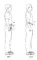
- FIG. 7is a perspective view of the infusion pump system of FIG. 5 worn on clothing of a user.
- FIG. 8is a perspective view of an infusion pump system worn on skin of a user, in accordance with particular embodiments.
- FIGS. 9 , 10 , and 11are perspective views of a pump device being detached from a controller device, in accordance with some embodiments.
- FIGS. 12-13are perspective views of the pump device of FIGS. 11-12 being discarded and the controller device of FIGS. 11-12 being reused with a new pump device.
- FIGS. 14-15are perspective views of the new pump device of FIG. 12 being attached to the controller device of FIG. 12 .
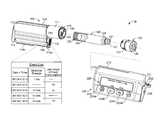
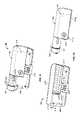
- FIG. 15is an exploded perspective view of a controller device for an infusion pump system, in accordance with some embodiments.
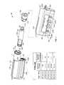
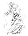
- FIG. 16is an exploded perspective view of a pump device for an infusion pump system, in accordance with some embodiments.
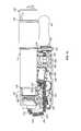
- FIG. 17is a perspective view of a portion of the pump device of FIG. 16 .
- FIG. 18is a top view of a portion of the pump device of FIG. 16 .
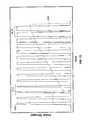
- FIG. 19is an example of an event log that can be stored in a memory device in a pump device.
- FIG. 20is an example of user profile data that can be stored in a memory device in a pump device.
- FIG. 21is a flow diagram of how a user can update a software program in the controller device.
- FIG. 22is a graphs depicting a variety of drive system energy requirement profiles.
- FIG. 23is graphs depicting an example of a pattern of delivered voltage pulses and an energy profile created by that pattern of delivered voltage pulses.
- an infusion pump system 10can include a pump device 100 and a controller device 200 that communicates with the pump device 100 .
- the pump device 100can include a housing structure 110 that defines a cavity 116 in which a fluid cartridge 120 can be received.
- the pump device 100also can include a cap device 130 to retain the fluid cartridge 120 in the cavity 116 of the housing structure 110 .
- the pump device 100can include a drive system (described in more detail below) that advances a plunger 125 in the fluid cartridge 120 so as to dispense fluid therefrom.
- the controller device 200communicates with the pump device 100 to control the operation of the drive system.
- the usercan (in some embodiments) conveniently wear the infusion pump system 10 on the user's skin under clothing or in the user's pocket while receiving the fluid dispensed from the pump device 100 .
- the controller device 200may be configured as a reusable component that provides electronics and a user interface to control the operation of the pump device 100 .
- the pump device 100can be a disposable component that is disposed of after a single use.
- the pump device 100can be a “one time use” component that is thrown away after the fluid cartridge 120 therein is exhausted. Thereafter, the user can removably attach a new pump device 100 ′ (having a new medicine cartridge 120 ′) to the reusable controller device 200 for the dispensation of fluid from a new fluid cartridge 120 ′.
- the useris permitted to reuse the controller device 200 (which may include complex or valuable electronics) while disposing of the relatively low-cost pump device 100 after each use.
- the controller device 200which may include complex or valuable electronics
- Such a pump system 10can provide enhanced user safety as a new pump device 100 (and drive system therein) is employed with each new fluid cartridge 120 .
- a usermay use a controller device 200 to dispense more than one drug in sequence from different pump devices 100 , which may mean that a user swaps the pump devices 100 before the fluid cartridge 120 is empty.
- a diabeticmay use the controller device 200 and a series of pump devices 100 for dispensation of more than one type of insulin.
- a usermay detach and reattach a pump device 100 from the controller device 200 before discarding the pump device 100 when the fluid cartridge 120 is exhausted.
- the detachment and reattachment of the pump device 100 from the controller device 200can be accommodated.
- a memory device 318 included in the pump device 100can store data related to the pump device 100 .
- the memory device 318can be configured to store pump-related data such as: a unique serial number designated for the pump device 100 ; a manufacturer identifier code; a lot number code; a manufacturing date stamp; a model number; compatibility codes used to ensure that the pump device 100 , the controller device 200 , and the fluid cartridge 120 can work together; a energy requirement profile for the drive system of the pump device; an event log including time and date stamped records of pump activations, user input, and/or sensor input (refer to FIGS.
- the data stored on the memory device 318can be received by the controller device 200 or an external device for use by a physician or practitioner.
- the controller device 200can write data onto the memory device 318 . Recording this data on the memory device 318 within the disposable pump device can be useful, particularly when a user might detach and reattach a pump device 100 multiple times from the controller device 200 before discarding the pump device 100 when the fluid cartridge 120 is empty.
- the pump device 100is configured to removably attach to the controller device 200 in a manner that provides a secure fitting, an overall compact size, and a reliable electrical connection that is resistant to water migration.
- the controller device 200can include a housing 210 having a number of features that mate with complementary features of the pump housing 110 .
- the controller device 200can removably attach with the pump device 100 in a generally side-by-side configuration while not fully surrounding the pump housing 110 .
- the pump device 100 and the controller device 200can be separate components that fit together, but the overall size of the combined assembly is reduced because there is no requirement for one component (e.g., the controller device) to completely surround or envelop the second component (e.g., the pump device).
- the compact sizepermits the infusion pump system 10 to be discrete and portable (as described below in connection with FIGS. 6-8 ).
- at least one of the pump device 100 or the controller device 200can include a release member that facilitates an easy-to-use detachment and replacement process.
- the pump system 10can be a medical infusion pump system that is configured to controllably dispense a medicine from the cartridge 120 .
- the fluid cartridge 120can contain a medicine 126 ( FIG. 1 ) to be infused into the tissue or vasculature of a targeted individual, such as a human or animal patient.
- the pump device 100can be adapted to receive a medicine cartridge 120 in the form of a carpule that is preloaded with insulin or another medicine for use in the treatment of Diabetes (e.g., Byetta®, Symlin®, or others).
- a medicine cartridge 120may be supplied, for example, by Eli Lilly and Co. of Indianapolis, Ind.
- the fluid cartridge 120may have other configurations.
- the fluid cartridge 120may comprise a reservoir that is integral with the pump housing structure 110 (e.g., the fluid cartridge 120 can be defined by one or more walls of the pump housing structure 110 that surround a plunger to define a reservoir in which the medicine is injected or otherwise received).
- the pump device 100can include one or more structures that interfere with the removal of the medicine cartridge 120 after the medicine cartridge 120 is inserted into the cavity 116 .
- the pump housing structure 110can include one or more retainer wings 119 that at least partially extend into the cavity 116 to engage a portion of the medicine cartridge 120 when the medicine cartridge 120 is installed therein.
- Such a configurationmay facilitate the “one-time-use” feature of the pump device 100 and ensure that an data stored on the memory device 318 is reflective of the one and only fluid cartridge 120 .
- the retainer wings 119can interfere with attempts to remove the medicine cartridge 120 from the pump device 100 , thus ensuring that the pump device 100 will be discarded along with the medicine cartridge 120 after the medicine cartridge 120 is emptied, expired, or otherwise exhausted. Accordingly, the pump device 100 can operate in a tamper-resistant and safe manner because the pump device 100 can be designed with predetermined life expectancy (e.g., the “one-time-use” feature in which the pump device is discarded after the medicine cartridge 120 is emptied, expired, or otherwise exhausted).
- the controller device 200can be removably attached to the pump device 100 so that the two components are mechanically mounted to one another in a fixed relationship. Such a mechanical mounting can form an electrical connection between the removable controller device 200 and the pump device 100 .
- the controller device 200can be in electrical communication with a portion of a drive system (not shown in FIGS. 1-3 ) of the pump device 100 .
- the controller device 200can also then be adapted to read data from (and in some embodiments write data to) the memory device 318
- the pump device 100can include a drive system that causes controlled dispensation of the medicine or other fluid from the cartridge 120 .
- the drive systemincrementally advances a piston rod (not shown in FIGS. 1-3 ) longitudinally into the cartridge 120 so that the fluid is forced out of an output end 122 .
- a septum 121 ( FIG. 1 ) at the output end 122 of the fluid cartridge 120can be pierced to permit fluid outflow when the cap device 130 is connected to the pump housing structure 110 (described in more detail below).
- the controller device 200communicates electronic control signals via a hardwire-connection (e.g., electrical contacts or the like) to the drive system or other components of the pump device 100 .
- the drive system of the pump device 100causes medicine to incrementally dispense from the medicine cartridge 120 .
- the pump device 100can include an electrical connector 118 (e.g., having conductive pads, pins, and the like) that are exposed to the controller device 200 and that mate with a complementary electrical connector (refer to connector 218 in FIG. 3 ) on the adjacent face of the controller device 200 .
- the electrical connectors 118 and 218provide the electrical communication between the control circuitry (refer, for example, to FIG. 16 ) housed in the controller device 200 and at least a portion of the drive system or other components of the pump device 100 .
- the electrical connectors 118 and 218can permit the transmission of electrical control signals to the pump device 100 and the reception of feedback signals (e.g., sensor signals) from particular components within the pump device 100 .
- electrical connectorscan permit for the transmission of data between the memory device 318 and the controller device 200 .
- the infusion pump system 10can include a gasket 140 that provides a seal that is resistant to migration of external contaminants when the pump device 100 is attached to the controller device 200 .
- the infusion pump system 10can be assembled into a water resistant configuration that protects the electrical interconnection from water migration (e.g., if the user encounters water while carrying the pump system 10 ).
- the controller device 200can include a user interface 220 that permits a user to monitor the operation of the pump device 100 .
- the user interface 220can include a display device 222 and one or more user-selectable buttons (e.g., four buttons 224 a , 224 b , 224 c , and 224 d in this embodiment).
- the display device 222can include an active area in which numerals, text, symbols, images, or a combination thereof can be displayed (refer, for example, to FIG. 2 ).
- the display device 222can be used to communicate a number of settings or menu options for the infusion pump system 10 .
- the usermay press one or more of the buttons 224 a , 224 b , 224 c , and 224 d to shuffle through a number of menus or program screens that show particular settings and data (e.g., review data that shows the medicine dispensing rate, the total amount of medicine dispensed in a given time period, the amount of medicine scheduled to be dispensed at a particular time or date, the approximate amount of medicine remaining in the cartridge 120 , or the like).
- the usercan adjust the settings or otherwise program the controller device 200 by pressing one or more buttons 224 a , 224 b , 224 c , and 224 d of the user interface 220 .
- an event log on the memory device 318can record user interaction with the user interface (e.g., storing the date and time for each adjustment in settings or other programming of the controller device).
- the userwhen the controller device 200 is connected to the pump device 100 , the user can be provided with the opportunity to readily monitor the infusion pump operation by simply viewing the user interface 220 of the controller device 200 connected to the pump device 100 .
- Such monitoring capabilitiesmay provide comfort to a user who may have urgent questions about the current operation of the pump device 100 .
- the usercan readily operate the user interface 220 of the controller device 200 , which is removably attached to the pump device 100 , without the requirement of locating and operating a separate monitoring module.
- the controller device 200can be removably attached to the pump device 100 in a side-by-side arrangement.
- the pump device 100may be moved in a longitudinal direction (e.g., refer to direction 219 in FIG. 13 ) toward the controller device 200 until the complementary features connect and secure the separate components in the side-by-side arrangement.
- the pump device 100 and the controller device 200can be separate components that fit together, but the overall size of the combined assembly can be reduced because there is no requirement for one component (e.g., the controller device or pump device) to surround or envelop the second component (e.g., the pump device or controller device).
- the pump device 100 and controller device 200can be readily attached together with a “one-movement” process that is convenient to the user.
- the controller device 200can include a controller housing structure 210 having a number of features that are configured to mate with complementary features of the pump housing structure 110 so as to form a releasable mechanical connection.
- the pump housing structure 110can include a barrel 111 that mates with a complementary barrel channel 211 of the controller housing 210 .
- the pump housing 110can include slider channel 112 that slidably engages a complementary rail 212 defined by the controller housing 210 .
- the slider channel 112can guide the relative motion between the pump device 100 and the controller device 200 in the longitudinal direction during the attachment process.
- the pump housing 110can include a segmented rail 114 a - b ( FIG.
- the pump housing 110can include an extension 113 ( FIG. 1 ) that mates with a depression 213 ( FIG. 5 ) in the controller housing 210 when the pump device 100 is fully attached to the controller device 200 . It should be understood that, in other embodiments, other features or connector devices can be used to facilitate the side-by-side mounting arrangement.
- the memory device 318can include a number of compatibility codes corresponding to these features and the controller device 200 can detect those compatibility codes to ensure that the controller device 200 and the pump device 100 will properly mate.
- a controller device 200can indicate that a pump device 100 is not compatible if the pump device does not include a suitable set of compatibility codes for controller device 200 .
- the pump device 100 and the controller device 200can be attached in a manner that is resistant to migration of external contaminants (e.g., water, dirt, and the like) both into the pump housing structure 110 and the controller housing structure 210 .
- external contaminantse.g., water, dirt, and the like
- the electrical connector 118 ( FIG. 5 ) of the pump device 100is directed toward engagement with the mating connector 218 ( FIG. 4 ) of the controller device 200 .
- the gasket 140is compressed between the adjacent surfaces of the pump housing 110 and the controller housing 210 .
- the gasket 140thereby forms a water-resistant seal between the ambient environment and the mated connectors 118 and 218 . Accordingly, in particular circumstances, the infusion pump system 10 can be assembled into a “water tight” configuration that protects sensitive internal components from water migration in the event that the user encounters water while wearing the pump system 10 . In one example, the gasket 140 can resist migration of water to the electrical connectors 118 and 218 even when the system 10 is submerged underwater (e.g., in a pool, in a bath, or the like) for an extended period of time, such as at least 10 minutes, at least 30 minutes, at least one hour, at least two hours, and preferably at least four hours.
- the infusion pump system 10can include one or more seals that are arranged to hinder migration of external contaminants between the cap device 130 and the pump housing 110 into the cavity 116 of the pump device 100 .
- the seal 131 arranged between the cap device 130 and the barrel 111can provide an effective water-resistant seal against water migration into the cavity.
- the medicine cartridge 120 and pump drive system(not shown in FIGS. 4-5 ) can be protected during operation.
- some embodiments of the infusion pump system 10may employ a power source arranged in pump device 100 or the controller device 200 that draws upon surrounding air for optimum operation. Because the controller device 200 and the pump device 100 may be sealed to resist water migration during normal usage, a water-resistant vent instrument 145 can be used to provide the air to the power source without permitting migration of water therethrough.
- the pump device 100can contain a first power source 345 in the form of a zinc-air cell battery (refer to FIGS. 17 and 18 ), which draws upon the surrounding air during operation.
- the pump housing 110can be sealed to protect the internal drive system and medicine cartridge from water migration.
- the pump housing 10can include a water-resistant vent instrument 145 disposed proximate to the first power source 345 (e.g., a zinc-air cell battery) so that some air may pass through the vent 145 and toward the first power source 345 .
- the water-resistant vent instrument 145can include one or more layers of a material that is permeable to air and resistant to passage of liquids such as water.
- the water-resistant vent instrument 145can include one or more layers of a GORE-TEX material to resist the migration of water into the pump device while permitting the passage of air toward the battery.
- the pump device 100 and the controller device 200can be mounted to one another so that the assembled system 10 is resistant to water migration both into the pump housing structure 110 and the controller housing structure 210 .
- Such a configurationcan also provide water-resistant protection for the electrical connection between the pump device 100 and the controller device 200 .
- the sensitive internal components in the controller device 200 and the pump device 100can be reliably protected from water migration if the user encounters water (e.g., rain, incidental splashing, and the like) while using the pump system 10 .
- the infusion pump system 10can be configured to be portable and can be wearable and concealable.
- a usercan conveniently wear the infusion pump system 10 on the user's skin (e.g., skin adhesive) underneath the user's clothing or carry the pump device 100 in the user's pocket (or other portable location) while receiving the medicine dispensed from the pump device 100 .
- the drive system of the pump device 100can be arranged in a compact manner so that the pump device 100 has a reduced length.
- the overall length of the pump housing structure 110(which contains medicine cartridge and the drive system) can be about 7 cm to about 10 cm and about 7 cm to about 9 cm (about 8.3 cm or less in some embodiments).
- the pump housing structure 110can have an overall height of about 2 cm to about 4 cm (about 3.1 cm or less in some embodiments) and an overall thickness of about 8 mm to about 20 mm (about 17.5 mm or less in one embodiment).
- the pump system 10is shown in FIG. 6 as being held in a user's hand 5 so as to illustrate an exemplary size of the system 10 in accordance with some embodiments.
- This embodiment of the infusion pump system 10is compact so that the user can wear the portable infusion pump system 10 (e.g., in the user's pocket, connected to a belt clip, adhered to the user's skin, or the like) without the need for carrying and operating a separate module.
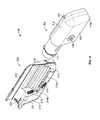
- the cap device 130 of the pump device 100can be configured to mate with an infusion set 146 .
- the infusion set 146can be a tubing system that connects the infusion pump system 10 to the tissue or vasculature of the user (e.g., to deliver medicine into the tissue or vasculature under the user's skin).
- the infusion set 146can include a flexible tube 147 that extends from the pump device 100 to a subcutaneous cannula 149 retained by a skin adhesive patch 148 that secures the subcutaneous cannula 149 to the infusion site.
- the skin adhesive patch 148can retain the infusion cannula 149 in fluid communication with the tissue or vasculature of the user so that the medicine dispensed through the tube 147 passes through the cannula 149 and into the user's body.
- the cap device 130can provide fluid communication between the output end 122 ( FIG. 1 ) of the medicine cartridge 120 and the tube 147 of the infusion set 146 .
- the infusion pump system 10can be pocket-sized so that the pump device 100 and controller device 200 can be worn in the user's pocket 6 or in another portion of the user's clothing.
- the usermay desire to wear the pump system 10 in a more discrete manner. Accordingly, the user can pass the tube 147 from the pocket 6 , under the user's clothing, and to the infusion site where the adhesive patch 148 can be positioned.
- the pump system 10can be used to delivery medicine to the tissues or vasculature of the user in a portable, concealable, and discrete manner.
- the infusion pump system 10can be configured to adhere to the user's skin 7 directly at the location in which the skin is penetrated for medicine infusion.
- a rear surface 102 ( FIG. 3 ) of the pump device 100can include a skin adhesive patch so that the pump device 100 can be physically adhered to the skin of the user at a particular location.
- the cap device 130can have a configuration in which medicine passes directly from the cap device 130 into an infusion cannula 149 that is penetrated into the user's skin.
- the usercan temporarily detach the controller device 200 (while the pump device 100 remains adhered to the skin 7 ) so as to view and interact with the user interface 220 .
- the infusion pump system 10can be operated such that the pump device 100 is a disposable, non-reusable component while the controller device 200 is a reusable component.
- the pump device 100may be configured as a “one-time-use” device that is discarded after the medicine cartridge is emptied, expired, or otherwise exhausted.
- the pump device 100can be designed to have an expected operational life of about 1 day to about 30 days, about 1 day to about 20 days, about 1 to about 14 days, or about 1 day to about 7 days-depending on the volume of medicine in the cartridge 120 , the dispensation patterns that are selected for the individual user, and other factors.
- a medicine cartridge 120 containing insulincan have an expected usage life about 7 days after the cartridge is removed from a refrigerated state and the septum 121 is punctured.
- the dispensation pattern selected by the usercan cause the insulin to be emptied from the medicine cartridge 120 before the 7-day period. If the insulin is not emptied from the medicine cartridge 120 after the 7-day period, the remaining insulin can become expired sometime thereafter. In either case, the pump device 100 and the medicine cartridge 120 therein can be discarded after exhaustion of the medicine cartridge 120 (e.g., after being emptied, expired, or otherwise not available for use).
- the controller device 200may be reused with subsequent new pump devices 100 ′ and new medicine cartridges 120 ′.
- the control circuitry, the user interface components, and other components that may have relatively higher manufacturing costscan be reused over a longer period of time.
- the controller device 200can be designed to have an expected operational life of about 1 year to about 7 years, about 2 years to about 6 years, or about 3 years to about 5 years—depending on a number of factors including the usage conditions for the individual user. Accordingly, the user can be permitted to reuse the controller device 200 (which can include complex or valuable electronics) while disposing of the relatively low-cost pump device 100 after each use.
- Such a pump system 10can provide enhanced user safety as a new pump device 100 ′ (and drive system therein) is employed with each new fluid cartridge 120 .
- the pump devices 100may be disposable, a user can disconnect and reconnect a pump devices 100 multiple times before discarding the pump devices 100 when the medicine cartridges 120 are empty.
- the same controller device 200can be reused with a new pump device 100 ′ having a new medicine cartridge 120 ′ retained therein, and the previously used pump device 100 can be discarded with the exhausted medicine cartridge 120 .
- the new pump device 100 ′( FIG. 11 ) can have a similar appearance, form factor, and operation as the previously used pump device 100 , and thus the new pump device 100 ′ can be readily attached to the controller device 200 for controlled dispensation of medicine from the new medicine cartridge 120 ′.
- additional pump devicescan be used having different appearances, different form factors, and/or different operations.
- a usercan use the reusable controller with pump devices 100 including different medications.
- the usercan prepare the new pump device 100 for use with the controller device 200 .
- the usermay insert the new medicine cartridge 120 ′ in the cavity 116 of the new pump device 100 ′ and then join the cap device 130 to the pump housing to retain the new medicine cartridge 120 ′ therein (refer, for example, to FIG. 1 ).
- the tubing 147 of the infusion set 146is not shown in FIG. 11 , it should be understood that the tubing 147 can be attached to the cap device 130 prior to the cap device 130 being joined with the housing 110 .
- a new infusion set 146can be connected to the cap device 130 so that the tubing 147 can be primed (e.g., a selected function of the pump device 100 controlled by the controller device 200 ) before attaching the infusion set patch to the user's skin.
- the new medicine cartridge 120 ′may be filled with medicine such that the plunger 125 is not viewable through the barrel 111 .
- the new pump device 100 ′can be removably attached to the controller device 200 to assemble into the infusion pump system 10 for delivery of medicine to the user.
- the usermay prepare the new pump device 100 ′ for use by pulling the removable tab 141 away from the pump housing 110 .
- the new pump device 100 ′can include the removable tab 141 to seal the battery in the unused pump device 100 ′ and thereby maintain the battery in a storage mode (refer, for example, to FIG. 12 in which the removable tab 141 is arranged to cover an internal face of the vent 115 ).
- the removable tab 141can be pulled away from the pump housing 110 (and away from the battery therein), which switches the battery into an activation mode.
- the shelf-life of the pump device 100 ′(prior to usage with the controller device 200 ) may be extended by sealing the battery in a storage mode because little, if any, energy is dissipated from the battery when in the storage mode.
- the guided motion in the longitudinal direction 219provides the user with a convenient “one-movement” process to attach the pump device 100 ′ and the controller device 200 .
- the usercan readily slide the pump device 100 ′ and the controller device 200 toward one another in a single movement (e.g., in the longitudinal direction) that causes both a physical connection and an electrical connection.
- the infusion pump system 10can permit users to readily join the pump device 100 ′ and the controller device 200 without compound or otherwise difficult hand movements a feature that can be beneficial to child users or to elderly users.
- the controller device 200houses a number of components that can be reused with a series of successive pump devices 100 .
- the controller device 200can include control circuitry 240 arranged in the controller housing 210 configured to communicate control signals to the drive system of the pump device 100 .
- the control circuitry 240can include a main processor board 242 in communication with a power supply board 244 .
- the control circuitry 240can include at least one processor 243 that coordinates the electrical communication to and/or from the controller device 200 (e.g., communication between the controller device 200 and the pump device 100 ).
- the processor 243can be arranged on the main processor board 242 along with a number of other electrical components, such as memory devices.
- the control circuitry 240can be programmable, i.e., the user may provide one or more instructions to adjust a number of settings for the operation of the infusion pump system 10 . Such settings may be stored in the memory devices arranged in the control circuitry 240 . Furthermore, the control circuitry 240 can include one or more dedicated memory devices storing executable software instructions for the processor 243 . The control circuitry 240 can include other components, such as sensors, that are electrically connected to the main processor board 242 . For example, at least a portion of the occlusion sensor 250 (not shown in FIG. 15 ) can be electrically connected to the main processor board 242 via a flexible circuit substrate and/or one or more wires.
- the user interface 220 of the controller device 200can include input components and/or output components, that are electrically connected to the control circuitry 240 .
- the user interface 220can include a display device 222 having an active area that outputs information to a user and four buttons 224 a - d that receive input from the user.
- the display device 222can be used to communicate a number of settings or menu options for the infusion pump system 10 .
- control circuitry 240can receive input commands from a user's button selections and thereby cause the display device 222 to output a number of menus or program screens that show particular settings and data (e.g., review data that shows the medicine dispensing rate, the total amount of medicine dispensed in a given time period, the amount of medicine scheduled to be dispensed at a particular time or date, the approximate amount of medicine remaining the cartridge 120 , the amount of battery life remaining, or the like).
- the controller circuit 240can be programmable to cause the controller circuit 240 to change any one of a number of settings for the infusion pump system 100 .
- control circuitry 240can include a cable connector (e.g., a USB connection port or another data cable port) that is accessible on an external portion of the controller housing 210 .
- a cablecan be connected to the control circuitry 240 to upload data or program settings to the controller circuit or to download data from the control circuitry 240 .
- datacan be downloaded from the control circuitry 240 (via the cable connector) to a computer system of a physician or a user for purposes of analysis and program adjustments.
- the data cablecan also provide recharging power.
- the pump device 100can include a first power source 345 (refer to FIGS. 16-18 ) capable of transmitting electrical energy to the controller device 200 when the pump device 100 is attached to the controller device 200 . Such energy transmission is described in more detail below.
- the first power source 345can be maintained in a storage mode and then switched to an activation mode when the pump device 100 is used to dispense medicine.
- the storage modecan provide a long shelf life of storage for the first power source 345 .
- the first power sourcecan retain a substantial portion of its charge for a period of more than six months, more than one year, or more than two years. As shown in FIGS.
- the first power source 345can be equipped with a removable tab 141 that seals the first power source 345 to maintain it in the storage mode.
- the removable tab 141can be pulled away from the pump housing 110 , which switches the first power source into the activation mode.
- the first power source 345can dispense electrical energy for a usage period in which the pump device is used.
- the first power source 345can provide electrical energy to other components (e.g., the second power source 245 ) over a usage period of about one week to about one month (e.g., about two weeks).
- the first power source 345can include a disposable and/or non-rechargeable battery (e.g., a zinc-air cell).
- the first power source 345can have a large volumetric energy density compared to the second power source 245 .
- the first power source 345can be a zinc-air cell battery that has a volumetric energy density of greater than about 900 Watt-hours/Liter (Wh/L), about 1000 Wh/L to about 1700 Wh/L, and about 1200 Wh/L to about 1600 Wh/L.
- the zinc-air cell batterycan have a long storage life, as described above.
- One exemplary zinc-air cell batteryis available from Duracell Corporation of Bethel, Conn., which can provide a potential voltage of about 1.1V to about 1.6V (about 1.2V to about 1.4 V, and about 1.3 V in one embodiment), a current output of about 8 mA to about 12 mA (about 10 mA in one embodiment), and a storage capacity of greater than about 600 mA ⁇ h (about 650 mA ⁇ h in one embodiment).
- the control circuitry 240 of the controller device 200can include a second power source 245 , which can be coupled to the power supply board 244 of the control circuitry 240 .
- the second power source 245can be a rechargeable energy source (e.g., a lithium polymer battery).
- the second power source 245can include a high current-output battery that is capable of discharging a brief current burst to power, for example, a drive system of the pump device 100 and can be capable of accepting and storing electrical energy over time (e.g., “trickle charge”).
- the second power source 245can be charged with energy supplied from the first power source 345 .
- the hard-wired transmission of electrical energy from the second power source 245 to the drive system 300can occur through the previously described connectors 118 and 218 ( FIGS. 6-7 ).
- the second power source 245can receive electrical energy from a power source housed in the pump device 100 (e.g., the first power source 345 ), from a plug-in wall charger, from a cable connector (e.g., a USB connection port that is connected to the control circuitry 240 ), or from another charging device (e.g., a charging cradle).
- the second power source 245can include a high current-output device that is contained inside the controller housing 210 .
- the second power source 245can be charged over a period of time (e.g., by a first power source 345 ) and can intermittently deliver high-current bursts to the drive system 300 over brief moments of time.
- the second power source 245can include a lithium-polymer battery
- the second power source 245 (e.g., lithium polymer battery) disposed in the controller device 200can have an initial current output that is greater than that of the first power source 345 (e.g., zinc-air cell battery) disposed in the pump device 100 , but the first power source 345 can have an energy density that is greater than the second power source 245 (e.g., the lithium polymer battery disposed in the controller device 200 can have a volumetric energy density of less than about 600 Wh/L).
- the second power source 245(e.g., lithium-polymer battery) can be readily rechargeable, which can permit the first power source 345 disposed in the pump device 100 to provide electrical energy to the second power source 245 for purposes of recharging.
- One exemplary lithium-polymer batterycan provide a initial current output of about greater than 80 mA (about 90 mA to about 110 mA, and about 100 mA in one embodiment) and a maximum potential voltage of about 4.0V to 4.4V (about 4.2 V in one embodiment).
- the second power source 245can include a capacitor device capable of being recharged over time and intermittently discharging a current burst to activate the drive system 300 . Additional embodiments of the power source 245 can include a combination of batteries and capacitors.
- the infusion pump system 10can have two power sources 345 and 245 —one arranged in the disposable pump device 100 and another arranged in the reusable controller device 200 —which can permit a user to continually operate the controller device 200 without having to recharge a battery via a plug-in wall charger or other cable.
- the controller device 200can be reusable with a number of pump devices 100 (e.g., attach the new pump device 100 ′ after the previous pump device 100 is expended and disposed)
- the second power source 245 in the controller devicecan be recharged over a period of time, each time when a new pump device 100 is connected thereto.
- Such a configurationcan be advantageous in those embodiments where the pump device 100 is configured to be a disposable, one-time-use device that attaches to a reusable controller device 200 .
- the “disposable” pump devices 100recharge the second power source 245 in the “reusable” controller device 200 , thereby reducing or possibly eliminating the need for separate recharging of the controller device 200 via a power cord plugged into a wall outlet.
- the pump device 100can include the drive system 300 that is controlled by the removable controller device 200 ( FIGS. 1-5 ). Accordingly, the drive system 300 can accurately and incrementally dispense fluid from the pump device 100 in a controlled manner.
- the drive system 300can include a flexible piston rod 370 that can be incrementally advanced toward the medicine cartridge 120 so as to dispense the medicine from the pump device 100 .
- At least a portion of the drive system 300can be mounted, to the pump housing 110 .
- the pump housing 110can include a chassis 107 , a shell portion 108 , and a cover mount 109 .
- the shell portion 108can be used to cover at least a portion of the drive system 300 .
- the shell 108can include an inner curved surface against which a curved section of a piston rod 370 rests.
- the cover mount 109may be assembled to the chassis 107 of the pump housing 110 to secure some components of the drive system 300 in position between the cover mount 109 and the chassis 107 .
- the “unused” or retracted portion of the piston rod 370can rest in a channel defined in the top of the cover mount 109 .
- the shell portion 108can slide over the cover mount 109 and join with the chassis 107 to form the assembled pump housing 110 .
- the drive system 300can include a battery powered actuator (e.g., reversible motor 320 or the like) that resets a ratchet mechanism 330 , a spring device (not shown) that provides the driving force to the ratchet mechanism 330 , and a drive wheel 360 that is rotated by the ratchet mechanism 330 to advance the flexible piston rod 370 toward the medicine cartridge 120 .
- a battery powered actuatore.g., reversible motor 320 or the like
- a spring devicenot shown
- a drive wheel 360that is rotated by the ratchet mechanism 330 to advance the flexible piston rod 370 toward the medicine cartridge 120 .
- the pump device 100can include one or more motion detectors coupled with the drive system 300 to provide feedback regarding the operation of the drive system 300 .
- the pump device 100can include a first motion detector 302 configured as a limit switch that detects when a portion of the ratchet mechanism has reached the limit of its travel and must thereafter stop movement or reverse direction.
- the pump device 100can include a second motion detector 307 in the form of a mechanical error switch that indicates whether components of the drive system 300 completed the desired motion for each drive cycle.
- the pump device 100can include a connector circuit 310 to facilitate the transfer of signals to and from the electrical connector 118 .
- the electrical connector 118 of the pump device 100can mate with the connector 218 ( FIG. 5 ) of the controller device 200 so that electrical communication can occur between the pump device 100 and the controller device 200 .
- the connector circuit 310can include a generally non-complex circuit 310 that does not include a processor or other relatively high-cost components.
- the connector circuit 310can operate as a passageway for the control signals (from the control circuitry 240 ( FIG. 15 ) of the controller device 200 ) to transmit to the drive system 300 (e.g., to the actuator 320 ).
- the reversible motor 320may be connected to the connector circuit 310 via one or more wires 304 .
- the connector circuit 310can also operate as a passageway for the electrical power from the first battery 345 ( FIG. 17 ) to pass to the controller device 200 for recharging of the second battery 245 ( FIG. 15 ).
- the first battery 345can be connected to the connector circuit 310 via one or more power contacts 305 .
- the connector circuit 310can operate as a passageway for feedback signals (e.g., from the motion detectors 302 and 307 ) to transmit to the control circuitry 240 ( FIG. 15 ) of the controller device 200 .
- the limit switch 302can be connected to the connector circuit 310 via one or more wires 306 (the one or more wires connecting the mechanical error switch 307 to the connector circuit 310 are not shown in FIG. 18 ).
- the connector circuit 310 in the pump device 100can include a memory device 318 that can store data regarding the pump device 100 , its operational history, and the user.
- the memory device 318can include nonvolatile memory (e.g., a flash memory chip), a Serial EEPROM powered by the power source in the controller device 200 , static RAM and a power source to allow the static RAM to retain the stored data, or a combination thereof.
- the memory device 318can be configured to store data such as: a unique serial number designated for the pump device 100 ; a manufacturer identifier code; a lot number code; a manufacturing date stamp; a model number; compatibility codes used to ensure that the pump device 100 , the controller device 200 , and the fluid cartridge 120 can work together; an energy requirement profile for the drive system of the pump device; user profile information; an event log including time and date stamped records of pump activations, user input, and/or sensor input; data regarding the pump battery life (e.g., the power remaining in the first power source 345 ); a drive cycle counter; an estimation of pump motor run time; the type of medicine contained in the fluid cartridge 120 ; and an estimation of the medicine remaining in the fluid cartridge 120 .
- datasuch as: a unique serial number designated for the pump device 100 ; a manufacturer identifier code; a lot number code; a manufacturing date stamp; a model number; compatibility codes used to ensure that the pump device 100 , the controller device 200 , and the fluid cartridge 120 can work
- the data stored on the memory device 318can be received by the controller device 200 or an external device for use by a physician.
- the controller device 200can communicate with the memory device 318 so as to write data onto the memory device 318 .
- some data on the memory device 318may be write protected as a safety precaution.
- the memory device 318can include data representing an estimate of the amount of medicine remaining in the fluid cartridge 120 . This data can be used by the controller device 200 to alert a user as to how much medicine is remaining in the pump device 100 . The estimate can be determined by identifying the cartridge capacity when the pump device 100 is first attached to the controller device 200 and subtracting an amount corresponding to the dose whenever the pump actuates.
- the controller device 200may determine cartridge capacity by a machine-readable indicia, by an optical, electrical, or mechanical feature of the cartridge, or by user input or selection.
- a manufacturermay identify a fluid cartridge 120 capacity and a dose volume for each pump actuation and record the fluid cartridge 120 capacity and the dose volume on the memory device.
- the controller device 200can subtract a dose volume from the fluid cartridge 120 capacity for each pump actuation and rewrite the new fluid cartridge 120 capacity to the memory device 318 . Accordingly, the controller device 200 can determine the remaining fluid cartridge capacity for a pump device 100 that has been partially used, detached, and again attached to the same or even a different controller device 200 .
- the memory device 318can include data indicating the battery life of a battery in the pump device 100 .
- the pump device 100can include a first power source 345 (e.g., a zinc-air cell), which may be used to charge the second power source 245 in the controller device 200 .
- the first power source 345can be a non-rechargeable battery.
- the memory device 318can store an indication of whether the battery life of first power source 345 in the pump device 100 is in a depleted or non-depleted state.
- the controller device 200can determine if the first power source 345 is in a depleted state by detecting a voltage output of the first power source 345 .
- the controller device 200can record an indication that the first power source 345 is depleted in the memory device 318 . This can prevent the controller device 200 from attempting to charge the second power source 245 within the controller device 200 with a depleted first power source 345 when a pump device 100 with a depleted first power source 345 is reattached to a controller device 200 .
- the memory device 318can include data estimating the amount of battery life remaining for the first power source 345 .
- the controller device 200can update this estimation by counting the number of recharge operations, calculating an amount of self discharge from a self-discharge rate for the first power source 345 , which can also be recorded in the memory device 318 , and a time and date stamp for the first use of the pump device, for when tab 141 was removed and/or a manufacturing date for the pump device.
- the memory device 318can include data indicating a medicinal fluid type, an unique serial number, a manufacturer identifier code, a manufacturing lot code, a manufacturing date and/or time stamp, and a model number.
- This datamay be useful quality control information that remains with the pump device 100 throughout its shelf-life and operational life. In some embodiments, this data may be write protected. If, for example, a manufacturing error is identified for a particular pump device 100 , the unique serial number, the manufacturer identifier code, the manufacturing lot code, the manufacturing date stamp, and/or the model number can be used to promptly identify when and/or where the error occurred.
- a manufacturing date and/or time stampcan also allow the controller device 200 to identify expired medication.
- this informationcan also be used to allow the controller device 200 to determine if the pump device 100 is compatible with the controller device 200 or if the pump device 100 includes the correct medical fluid cartridge 120 for the user.
- a usermay want to administer different medical fluids at different points in time with the same pump system 10 .
- Symlin®pramlintide acetate
- the usercan enter in data (e.g., via the user interface 220 ) about a meal prior to eating. After receiving data about the meal, the pump system 10 can request that the user remove the existing pump device 100 , containing insulin for example, and replace it with pump device 100 containing Symlin®.
- the pump system 10can cause a bolus of Symnlin® to be administered to the user. Upon infusion of the Symlin®, the pump system 10 can request that the insulin containing pump device 100 be re-attached.
- the memory device 318can include data indicating an event log including time and date stamped records of pump activations, user input, and/or sensor input.
- An visual representation of an event logcan be similar to that shown in FIG. 19 .
- the event logcan also record time and date stamps for when a pump device was first used with a controller device 200 and/or for each reattachment of the pump device 100 to the controller device 200 .
- This datacan allow for the reconstruction of events if there is a pump failure or other adverse event.
- This datacan also be retrieved by a physician or counselor to help check compliance with recommended dosages, diet protocols, and/or exercise regimes.
- the recorded data of a user's medical dosages and eating habitscan enhance the ability of the user or a medical practitioner to perform retrospective analysis and correction of the medicine delivery profile.
- the memory device 318can include compatibility codes that can be used to ensure that the pump device 100 , the controller device 200 , and the cartridge 120 can work together.
- controller device 200can be adapted such that only a physician can program which medications the user is allowed to receive and pump devices can include compatibility codes in the memory device 318 indicating whether the medication in the pump device is compatible with that controller's settings.
- some pump devicesmay require an updated or older controller (or that the controller includes include particular software) and the compatibility codes can indicate to a controller that that particular pump device should not be actuated by that controller.
- the memory device 318can include data indicative of user profile information.
- the memory device 318 in the disposable pump device 100can serve as a backup data system for the user profile information that is originally stored in the controller device 200 .
- Exemplary user profile datacan include a user's identifying information (e.g., name and/or social security number), the types of medication that a user is allowed to take, the different menu options available to the user, a user's physical characteristics (e.g., height, weight, gender, and the like), a user's insulin sensitivity (e.g., the users blood glucose to insulin ratio), how a user's blood glucose level responds to eating (e.g., blood glucose to carbohydrate ratio), how a user's blood glucose level responds to increased activity levels (e.g., blood glucose to activity ratio), treatment data (e.g., basal insulin rates, schedules, and/or profile), and the like.
- the controller device 200may transfer a user profile to the memory device 318 .
- the controller device 200can initially interrogate the memory 318 to determine if a pump device 100 already stores user profile data (e.g., stored as backup data when the pump device 100 was previously attached to another controller device 200 ). If a pump device 100 is detached and reattached to the same controller device 200 , the controller device 200 can verify that the pump device 100 is being for used the correct user by comparing the user profile data in the pump memory 318 to the user profile data stored in the controller device 200 . Furthermore, if the user has two controller devices 200 , the controller devices 200 should have the same user profile, thereby allowing the user to change controller devices 200 .
- user profile datae.g., stored as backup data when the pump device 100 was previously attached to another controller device 200 .
- the memory device 318can serve as a backup of the user profile in the case that the controller device 200 becomes inoperable or in the case that the user misplaces the controller device 200 .
- the controller device 200can be configured such that only a physician can set some of the user profile information (e.g., the types of medications allowed and/or the menu options available to the user).
- This operationmay facilitate that a user does not misuse the medication, that the user knows bow to control her blood glucose level (e.g., as a user becomes more knowledgeable about her condition, how to control her condition, and how the infusion pump system operates, a physician or practitioner can allow the user access to more advanced features of the infusion pump system), and verify that the controller device 200 does not dispense the wrong medication in the case where the user obtained a pump device 100 containing the wrong medication.
- the user profile information stored on the memory device 318 of a pump device 100can allow a user to more quickly make a clone of the controller device 200 , without the need for access to the original controller device 200 and without the need to seek out her physician to program a new controller device 200 .
- some of the information stored in the user profilecan be information determined by the controller device 200 during use with the user, as opposed to information programmed into the controller by either the user or a physician or practitioner.
- a new controller device 200when first attached to a pump device 100 having a user profile recorded from an old controller device 200 , can receive the user profile information from the memory 318 of the pump device 100 and allow the user to make a clone controller quickly and without the help of a physician or practitioner.
- the usercan review the user profile and accept or reject some portions of the profile (e.g., if the user's weight has changed).
- some portions of the profilemay be reviewed but not altered by the user without the intervention of a physician or practitioner (e.g., the types of medication allowed for the user or the menu options available to the user).
- data regarding the menu options available to the usercan be stored as user interface flags, which can be set at various levels (e.g., basic, intermediate, or advanced) or can specifically indicate which menu options are available to the user.
- the controller device 200may be configured to receive a user profile from the pump memory 318 only once. For example, the controller device 200 that has been previously programmed with user profile information from the pump memory 318 may thereafter ignore the user profile data when the pump device 100 is attached or can confirm that the user profile data matches the data previously stored in the controller device 200 .
- a new controller device 200can require the user to input data to confirm that the person in possession of the pump device 100 and the new controller device 200 is the person associated with the user profile.
- the new controller device 200can request that a user input a security code or a portion of the user's social security number. If the user does not input information that matches information recorded in the user profile, the new controller device 200 can decline to be programmed by the user profile stored in the memory device 318 of the pump device 100 . In some embodiments, the new controller device 200 can determine whether to store the user profile information on the memory device 318 of the pump device 100 based on a time and date stamp of when the user profile was uploaded. For example, an extended time period (e.g., about 6 months to about 12 months) from when the user profile was recorded on the memory device 318 can indicate that the user profile might be inaccurate.
- an extended time periode.g., about 6 months to about 12 months
- an individually removable memory devicecan be used to produce a user profile backup.
- a flash memory device having a USB connectioncan be attached to the controller device 200 to receive the user profile information.
- the backup copy of the user profile informationcould then be used to program a second controller device 200 if the first is damaged or misplaced.
- a date and time stamp of when the pump device 100 is first usedcan also ensure that the medicine in the pump device is not expired.
- this time and data stamp for when the pump device 100 was first usedcan be associated with when the user profile data was first transferred to the memory device 318 . This could identify the pump device to not only the first controller device 200 but also to additional controller clones.
- the infusion systemcan include a pump unit that houses the drive system, the control circuitry, the energy source, and the first memory device (without a removable controller housing).
- an individually removable memory devicecan be used to produce a user profile backup.
- a flash memory device having a USB connectioncan be attached to the pump unit to receive the user profile information from the control circuitry housed therein. The backup copy of the user profile information could then be used to program a second pump unit if the first is damaged or misplaced.
- the memory device 318can include a software program including machine executable instructions.
- the software programcan be a software update (e.g., a patch) for the controller operation software stored in a memory device of the control circuitry 240 or an entirely new software program for use with the controller device 200 .
- the software program stored in the memory device 318can also include identifying information that would allow the controller to determine whether the controller device 200 should receive, store, and/or execute the software update (e.g., whether the controller device 200 already included the software update or whether the software update is compatible with the particular model of the controller device 200 ).
- the controller device 200can query the user regarding whether to receive, store, and/or execute the software program.
- the process of receiving and updating the softwarecan require excessive time or add features that the user may not desire.
- the software program stored in the memory device 318can include an indication of whether the user should be queried regarding whether to receive, store, and/or execute the software program.
- the software program stored in the memory device 318can be automatically transmitted to the controller device 200 and executed by the control circuitry 240 without any user interaction.
- the software programcan update selected portions of machine executable instructions stored in the memory devices of the control circuitry 240 according to the software program transferred from the memory device 318 of the pump device 100 .
- a manufacturercan include the software program (e.g., a software update or patch) on the memory device 318 for use with the controller device 200 as a way of distributing a software update for the controller device 200 .
- the controller device 200can then perform the update either by overwriting its main program entirely with the new code, or by patching selected portions or subroutines according to a list in the software program of the pump memory 318 .
- a usercan receive a new pump device 100 including the software program and then releasably attach the new pump device 100 to their controller device 200 .
- the controller device 200can communicate with the memory device 318 in the pump device 100 to thereafter determine whether the software update is needed and/or compatible and, in some embodiments, query the user regarding whether to receive, store, and/or execute the software program.
- the controller device 200can then transfer the software program to memory of the control circuitry 240 and execute the software program now stored in the controller memory.
- the execution of the software programcan reprogram the controller device 200 .
- the software programcan be executed to perform various controller functions (e.g., to issue new user alerts, queries, or to allow for additional user input).
- the controller device 200can then be used to perform medicine dispensing operations.
- a physician or other medical practitionercan allow a user to update the software program on the controller device 200 by uploading a software program to the memory device 318 in the pump device 100 .
- the memory device 318can include pump motor run time or pump activation cycle count. This data can be used to limit use of the pump device 100 when it has been determined that the pump device 100 has exceeded its usable life.
- the drive cycle countercan also be useful for maintaining an accurate estimate of the volume of medicine that remains in the medicine cartridge 120 .
- the number of drive cycles that are required to incrementally advance the plunger 125 and thereby dispense a full medicine cartridge 120may be a predetermined value (e.g., in some embodiments, 6,300 drive cycles result in full dispensation of a new medicine cartridge). Accordingly, the drive cycle counter stored in the memory device 318 can keep track of the number of drive cycles that have occurred through the operational life of the pump device 100 .
- the controller device 200can store an updated value for the drive cycle counter stored in the memory device 318 .
- the controller device 200can alert the user that the medicine cartridge is approaching exhaustion.
- the drive cycle counter stored in the memory device 318remains local to the pump device 100 .
- the controller device 200can retrieve the value for the drive cycle counter stored in the memory device 318 and promptly ascertain how much medicine remains in the medicine cartridge 120 .
- the memory device 318can include a microcontroller.
- the memory device 318can include an EEPROM device integrated on-chip, and the microcontroller can be capable of running a communication protocol between the controller device 200 and the pump device 100 .
- the microcontrollercan, in some embodiments, multiplex signals from limit switches or other sensors required to operate the pump mechanics and/or confirm a series of operations directed by the controller.
- the microcontrollercan update the data stored on the memory device 318 regarding, for example, the number of drive cycles. By having the microprocessor update the data on the memory device 318 , the number of pin connectors between the pump device 100 and the controller device 200 can be reduced.
- the memory device 318can include a energy requirement profile for the drive system of the pump device 100 .
- the infusion pump system 10can include a pulse width modulation (PWM) system for controlling the power delivery to the drive system 300 .
- PWMpulse width modulation
- the drive system 300can define an energy requirement profile to perform a medicine dispensing operation (e.g., a torque profile) and this energy requirement profile can be stored on the memory device 318 .
- an energy requirement profilecan be similar to that shown in FIG. 22 . As shown in FIG.
- the PWM systemcan supply a pattern pulses of energy (voltage) 410 , of varying widths or with varying timing, to provide a delivered energy profile 400 that correlates to the energy requirement profile 470 (e.g., a torque profile) of the drive system 300 .
- the energy requirement profile 470e.g., a torque profile
- Different drive systems for different pump devicecan have different energy requirement profiles 470 (e.g., the different dashed lined profiles). Accordingly, by supplying an energy requirement profile 470 in the memory device 318 in the pump device 100 , the controller device 200 can readily determine the appropriate pattern of pulses of voltage to supply the drive system to provide the optimal amount of energy to the drive system of that particular pump device 100 .
- the energy requirement profilecan be developed to optimize a plurality of variables, such as power consumption, gear RPM, and the like and the PMW system can be configured to provide a pattern of voltage pulses correlated to the energy requirement profile from the second power source 245 (e.g., the lithium polymer battery) to the drive system.
- the torque profilecan be developed to maintain the motor 320 at a constant rate of rotation, in spite of changing torque demands on the motor 320 (e.g., from the drive system 300 ). Maintaining the motor 320 at a substantially constant rate of rotation can have the advantageous qualities of reducing power consumption, reducing vibration, and/or increasing the life of the motor 320 .
- the controller device 200can detect whether the drive system 300 completes the medicine dispensing operation and adjust the delivered energy profile to meet the energy requirement profile needed for the drive system.
- the controller device 200can store the delivered energy profile as an adjusted energy requirement profile for that particular pump device 100 .
- an energy requirement profile for a pump devicecan be stored in the memory device 318 in the pump device.
- the controller device 200can update the energy requirement profile stored on the memory device 318 for subsequent medicine dispensing operations.
- a drive systemcan have varying energy requirement profiles 410 (as shown in the dotted lines).
- This torque curvecan represent the torque that is estimated to maintain a constant RPM of the motor 320 when rotating in a first rotational direction that advances the ratchet mechanism 330 to elongate the spring device 350 .
- This torque curve 400can be a sum of, for example, the torque curve associated with initial motor 320 startup, the torque curve associated with the no load torque of the motor 320 , the torque curve associated with the torque required to elongate the spring device 350 , and the torque curve associated with the mechanical advantage that is achieved due to the connection of the ratchet mechanism 330 to the gear system.
- the torque curve 470here is described as a sum of other torque curves, the torque curve 470 could be determined from empirical data, for example by testing one or more pump devices 100 to determine the actual torque at any given time in a pump cycle required to keep the rate of rotation of the motor 320 substantially constant. In some embodiments, the torque curve 470 determined from a sum of other torque curves could be recorded in the memory device 318 at the time of manufacture of the pump device 100 . In some embodiments, a manufacturer can test the pump device 100 after manufacture to find the optimal torque curve 470 and record that on the memory device 318 . In other embodiments, a controller device 200 could determine the optimal torque curve for a particular pump device 100 and record the torque curve on the memory device 318 .
- a tachometercan be used to determine an optimum PWM profile for a particular pump device.
- motor commutationcan be used as a tachometer surrogate.
- the commutation signalsare already in digital form and these digital signals can be used as a tachometer signal by measuring their frequency and/or period. It may also be possible to use the actuation period of the drive (interval between limit switch actuations) to provide feedback to the PWM controller to optimize the profile.
- a PWM profile that provides more power than necessarywill result in a faster actuation time, while a PWM profile that fails to provide the optimal amount of power can result in a sluggish actuation or even fail to start the actuation process.
- the controller device 200can detect a time period for the drive system to complete a medicine dispensing operation and adjust the delivered energy profile to meet the energy requirement profile needed for the drive system. For example, a PWM profile that provides more energy than required can result in a more rapid actuation of the pump device. If the controller device 200 detects that the drive system completed the medicine dispensing operation in less time than a predetermined actuation time, then the controller device 200 can downwardly adjust the delivered energy profile. If the actuation takes more time than a predetermined actuation time, the controller device 200 can upwardly adjust the delivered energy profile. For example, a controller device 200 can correct a torque curve 470 initially recorded in the memory device 318 using one of the torque curves 470 shown in FIG.
- the controller device 200can store the delivered energy profile as an adjusted energy requirement profile for the pump.
- an energy requirement profile for a pump devicecan be stored in the memory device 318 in the pump device.
- the controller device 200can update the energy requirement profile stored on the memory device 318 for subsequent medicine dispensing operations.
- the controller device 200can also detect whether the actuation of the pump actually begins and upwardly adjust the delivered energy profile if the pump fails to start.
- a PWM controller systemcan work by supplying intermittent, full-voltage, pulses of energy to supply a given amount of energy to a device (e.g., the motor 320 ) during a period of time.
- the controller device 200can supply a variable voltage to the motor 320 to achieve a pre-determined torque curve (e.g., the continuous torque curve 470 shown in FIG. 21 ) using a digital-to-analog (D/A) converter and a power amplifier.
- D/Adigital-to-analog
- the system 10can use a series of pulses, all at the full output voltage (e.g., a PWM system) to simulate a continuous torque curve (e.g., torque curve 400 ) without the need for a D/A converter or power amplifier and without the power loss associated with these components.
- a PWM torque curve 400is depicted by a PWM torque curve 400 in FIG. 22 .
- the continuous torque curve 400has been superimposed on the PWM pattern 410 .
- the width of the delivered pulsesis decreased (as in pulses 412 ).
- the width of the delivered pulsesis increased (as in pulses 414 ).
- Embodiments of the system 10that employ a technique for limiting the torque supplied by the motor 320 have the advantage of controlling the RPM of the motor 320 , thus conserving energy and reducing vibration associated with over-revving of the motor 320 .
- the voltage received by the drive system 300 from the second power source 245can vary due to, for example, the charge remaining in the second power source 245 .
- these pulse widthscan be adjusted to supply the necessary torque.
- a scalar multiplecan be applied to the duration of the pulse width to correct for increased or decreased voltage. For example, if the sampled supply voltage to the motor 320 is 3.2 V, instead of the 4V rated output voltage, a scalar multiplier (e.g., 1.25) can be applied to the pulse width to correct for the change in voltage.
- the voltage of the pulsesremained constant, while the width of the pulses were adjusted to maintain the motor 320 at a constant RPM.
- the pulse widthscould be kept constant, while the pauses in between the pulses could be increased or decreased to simulate a pre-determined torque curve.
- the RPM of the motor 320could be monitored and the pulse widths could be adjusted based on the RPM of the motor 320 .
- the controller and/or the pump device 100can store a series of tables in memory for converting between a detected voltage output and an adjustment to the pulse duration (pulse widths) and/or pulse frequency. For example, a detected voltage output of between 3.4 V and 3.5 V can result in the use of a particular table defining a particular PWM pattern for voltage outputs in that range or a particular scalar multiplier adjustment to another PWM pattern stored in memory. The use of tables for particular voltage outputs can reduce the number of computations needed to adjust the PWM pattern for changes in voltage output.
Landscapes
- Health & Medical Sciences (AREA)
- Engineering & Computer Science (AREA)
- Biomedical Technology (AREA)
- Public Health (AREA)
- General Health & Medical Sciences (AREA)
- Primary Health Care (AREA)
- Epidemiology (AREA)
- Medical Informatics (AREA)
- Vascular Medicine (AREA)
- Anesthesiology (AREA)
- Heart & Thoracic Surgery (AREA)
- Hematology (AREA)
- Life Sciences & Earth Sciences (AREA)
- Animal Behavior & Ethology (AREA)
- Veterinary Medicine (AREA)
- General Business, Economics & Management (AREA)
- Business, Economics & Management (AREA)
- Chemical & Material Sciences (AREA)
- Bioinformatics & Cheminformatics (AREA)
- Medicinal Chemistry (AREA)
- Infusion, Injection, And Reservoir Apparatuses (AREA)
Abstract
Description
Claims (29)
Priority Applications (11)
| Application Number | Priority Date | Filing Date | Title |
|---|---|---|---|
| US11/851,986US7935105B2 (en) | 2007-09-07 | 2007-09-07 | Data storage for an infusion pump system |
| US11/851,989US8032226B2 (en) | 2007-09-07 | 2007-09-07 | User profile backup system for an infusion pump device |
| EP08830011AEP2206062A2 (en) | 2007-09-07 | 2008-07-16 | User profile backup system for an infusion pump device |
| EP08831000.8AEP2198380B1 (en) | 2007-09-07 | 2008-07-16 | Data storage for an infusion pump system |
| PCT/US2008/070148WO2009035761A2 (en) | 2007-09-07 | 2008-07-16 | Data storage for an infusion pump system |
| PCT/US2008/070150WO2009035762A2 (en) | 2007-09-07 | 2008-07-16 | User profile backup system for an infusion pump device |
| US13/095,632US8211093B2 (en) | 2007-09-07 | 2011-04-27 | Data storage for an infusion pump system |
| US13/251,869US8551070B2 (en) | 2007-09-07 | 2011-10-03 | User profile backup system for an infusion pump device |
| US13/468,077US8685002B2 (en) | 2007-09-07 | 2012-05-10 | Data storage for an infusion pump system |
| US14/047,142US9381302B2 (en) | 2007-09-07 | 2013-10-07 | User profile backup system for an infusion pump device |
| US14/228,535US9522232B2 (en) | 2007-09-07 | 2014-03-28 | Data storage for an infusion pump system |
Applications Claiming Priority (2)
| Application Number | Priority Date | Filing Date | Title |
|---|---|---|---|
| US11/851,986US7935105B2 (en) | 2007-09-07 | 2007-09-07 | Data storage for an infusion pump system |
| US11/851,989US8032226B2 (en) | 2007-09-07 | 2007-09-07 | User profile backup system for an infusion pump device |
Related Child Applications (1)
| Application Number | Title | Priority Date | Filing Date |
|---|---|---|---|
| US13/095,632DivisionUS8211093B2 (en) | 2007-09-07 | 2011-04-27 | Data storage for an infusion pump system |
Publications (2)
| Publication Number | Publication Date |
|---|---|
| US20090069746A1 US20090069746A1 (en) | 2009-03-12 |
| US7935105B2true US7935105B2 (en) | 2011-05-03 |
Family
ID=41105123
Family Applications (7)
| Application Number | Title | Priority Date | Filing Date |
|---|---|---|---|
| US11/851,989Active2028-05-26US8032226B2 (en) | 2007-09-07 | 2007-09-07 | User profile backup system for an infusion pump device |
| US11/851,986Active2029-08-03US7935105B2 (en) | 2007-09-07 | 2007-09-07 | Data storage for an infusion pump system |
| US13/095,632ActiveUS8211093B2 (en) | 2007-09-07 | 2011-04-27 | Data storage for an infusion pump system |
| US13/251,869ActiveUS8551070B2 (en) | 2007-09-07 | 2011-10-03 | User profile backup system for an infusion pump device |
| US13/468,077Active2027-11-04US8685002B2 (en) | 2007-09-07 | 2012-05-10 | Data storage for an infusion pump system |
| US14/047,142Active2028-05-18US9381302B2 (en) | 2007-09-07 | 2013-10-07 | User profile backup system for an infusion pump device |
| US14/228,535Active2028-08-12US9522232B2 (en) | 2007-09-07 | 2014-03-28 | Data storage for an infusion pump system |
Family Applications Before (1)
| Application Number | Title | Priority Date | Filing Date |
|---|---|---|---|
| US11/851,989Active2028-05-26US8032226B2 (en) | 2007-09-07 | 2007-09-07 | User profile backup system for an infusion pump device |
Family Applications After (5)
| Application Number | Title | Priority Date | Filing Date |
|---|---|---|---|
| US13/095,632ActiveUS8211093B2 (en) | 2007-09-07 | 2011-04-27 | Data storage for an infusion pump system |
| US13/251,869ActiveUS8551070B2 (en) | 2007-09-07 | 2011-10-03 | User profile backup system for an infusion pump device |
| US13/468,077Active2027-11-04US8685002B2 (en) | 2007-09-07 | 2012-05-10 | Data storage for an infusion pump system |
| US14/047,142Active2028-05-18US9381302B2 (en) | 2007-09-07 | 2013-10-07 | User profile backup system for an infusion pump device |
| US14/228,535Active2028-08-12US9522232B2 (en) | 2007-09-07 | 2014-03-28 | Data storage for an infusion pump system |
Country Status (3)
| Country | Link |
|---|---|
| US (7) | US8032226B2 (en) |
| EP (2) | EP2198380B1 (en) |
| WO (2) | WO2009035762A2 (en) |
Cited By (60)
| Publication number | Priority date | Publication date | Assignee | Title |
|---|---|---|---|---|
| US20110190701A1 (en)* | 2009-08-12 | 2011-08-04 | Roche Diagnostics Operations, Inc. | Methods, systems and devices for recording data |
| US20120220936A1 (en)* | 2007-09-07 | 2012-08-30 | Asante Solutions, Inc. | Data Storage for an Infusion Pump System |
| US8287495B2 (en) | 2009-07-30 | 2012-10-16 | Tandem Diabetes Care, Inc. | Infusion pump system with disposable cartridge having pressure venting and pressure feedback |
| US8333717B1 (en) | 2011-06-21 | 2012-12-18 | Yofimeter, Llc | Test unit cartridge for analyte testing device |
| US20130012917A1 (en)* | 2007-09-07 | 2013-01-10 | Asante Solutions, Inc. | Power Management Techniques for an Infusion Pump System |
| US8694331B2 (en) | 2008-04-01 | 2014-04-08 | Smiths Medical Asd, Inc. | Software features for medical infusion pump |
| US8852152B2 (en) | 2011-02-09 | 2014-10-07 | Asante Solutions, Inc. | Infusion pump systems and methods |
| US8961432B2 (en) | 2011-06-21 | 2015-02-24 | Yofimeter, Llc | Analyte testing devices |
| US9072827B2 (en) | 2012-03-26 | 2015-07-07 | Medimop Medical Projects Ltd. | Fail safe point protector for needle safety flap |
| US9149575B2 (en) | 2010-01-19 | 2015-10-06 | Medimop Medical Projects Ltd. | Needle assembly for drug pump |
| US9166313B2 (en) | 2013-04-30 | 2015-10-20 | Medimop Medical Projects | Power supply contact for installation of printed circuit board |
| US9173997B2 (en) | 2007-10-02 | 2015-11-03 | Medimop Medical Projects Ltd. | External drug pump |
| US9173998B2 (en) | 2013-03-14 | 2015-11-03 | Tandem Diabetes Care, Inc. | System and method for detecting occlusions in an infusion pump |
| USD747799S1 (en) | 2011-03-22 | 2016-01-19 | Medimop Medical Projects Ltd. | Cartridge |
| US9259532B2 (en) | 2010-01-19 | 2016-02-16 | Medimop Medical Projects Ltd. | Cartridge interface assembly |
| US9345836B2 (en) | 2007-10-02 | 2016-05-24 | Medimop Medical Projects Ltd. | Disengagement resistant telescoping assembly and unidirectional method of assembly for such |
| US9421323B2 (en) | 2013-01-03 | 2016-08-23 | Medimop Medical Projects Ltd. | Door and doorstop for portable one use drug delivery apparatus |
| US9421329B2 (en) | 2013-03-15 | 2016-08-23 | Tandem Diabetes Care, Inc. | Infusion device occlusion detection system |
| US9452261B2 (en) | 2010-05-10 | 2016-09-27 | Medimop Medical Projects Ltd. | Low volume accurate injector |
| US9463280B2 (en) | 2012-03-26 | 2016-10-11 | Medimop Medical Projects Ltd. | Motion activated septum puncturing drug delivery device |
| US9572926B2 (en) | 2009-09-15 | 2017-02-21 | Medimop Medical Projects Ltd. | Cartridge insertion assembly |
| US9656019B2 (en) | 2007-10-02 | 2017-05-23 | Medimop Medical Projects Ltd. | Apparatuses for securing components of a drug delivery system during transport and methods of using same |
| US9744297B2 (en) | 2015-04-10 | 2017-08-29 | Medimop Medical Projects Ltd. | Needle cannula position as an input to operational control of an injection device |
| US9795534B2 (en) | 2015-03-04 | 2017-10-24 | Medimop Medical Projects Ltd. | Compliant coupling assembly for cartridge coupling of a drug delivery device |
| US9889256B2 (en) | 2013-05-03 | 2018-02-13 | Medimop Medical Projects Ltd. | Sensing a status of an infuser based on sensing motor control and power input |
| US9987432B2 (en) | 2015-09-22 | 2018-06-05 | West Pharma. Services IL, Ltd. | Rotation resistant friction adapter for plunger driver of drug delivery device |
| US9987428B2 (en) | 2011-10-14 | 2018-06-05 | Amgen Inc. | Injector and method of assembly |
| US10071198B2 (en) | 2012-11-02 | 2018-09-11 | West Pharma. Servicees IL, Ltd. | Adhesive structure for medical device |
| US10071196B2 (en) | 2012-05-15 | 2018-09-11 | West Pharma. Services IL, Ltd. | Method for selectively powering a battery-operated drug-delivery device and device therefor |
| US10149943B2 (en) | 2015-05-29 | 2018-12-11 | West Pharma. Services IL, Ltd. | Linear rotation stabilizer for a telescoping syringe stopper driverdriving assembly |
| US10251813B2 (en) | 2015-03-04 | 2019-04-09 | West Pharma. Services IL, Ltd. | Flexibly mounted cartridge alignment collar for drug delivery device |
| US10255408B2 (en) | 2006-08-03 | 2019-04-09 | Smiths Medical Asd, Inc. | Interface for medical infusion pump |
| US10258736B2 (en) | 2012-05-17 | 2019-04-16 | Tandem Diabetes Care, Inc. | Systems including vial adapter for fluid transfer |
| US10279106B1 (en) | 2014-05-08 | 2019-05-07 | Tandem Diabetes Care, Inc. | Insulin patch pump |
| US10293120B2 (en) | 2015-04-10 | 2019-05-21 | West Pharma. Services IL, Ltd. | Redundant injection device status indication |
| US10335545B2 (en) | 2012-01-31 | 2019-07-02 | West Pharma. Services IL, Ltd. | Time dependent drug delivery apparatus |
| US10420880B2 (en) | 2007-10-02 | 2019-09-24 | West Pharma. Services IL, Ltd. | Key for securing components of a drug delivery system during assembly and/or transport and methods of using same |
| US10668213B2 (en) | 2012-03-26 | 2020-06-02 | West Pharma. Services IL, Ltd. | Motion activated mechanisms for a drug delivery device |
| US10780215B2 (en) | 2013-03-15 | 2020-09-22 | Tandem Diabetes Care, Inc. | Device and method for setting therapeutic parameters for an infusion device |
| US10850037B2 (en) | 2013-03-22 | 2020-12-01 | Amgen Inc. | Injector and method of assembly |
| US11049614B2 (en) | 2013-03-15 | 2021-06-29 | Tandem Diabetes Care, Inc. | Field update of an ambulatory infusion pump system |
| US11065381B2 (en) | 2015-10-05 | 2021-07-20 | E3D A.C.A.L. | Infusion pump device and method for use thereof |
| US11097055B2 (en) | 2013-10-24 | 2021-08-24 | Amgen Inc. | Injector and method of assembly |
| US11167086B2 (en) | 2008-09-15 | 2021-11-09 | West Pharma. Services IL, Ltd. | Stabilized pen injector |
| US11311674B2 (en) | 2016-01-21 | 2022-04-26 | West Pharma. Services IL, Ltd. | Medicament delivery device comprising a visual indicator |
| US11318254B2 (en) | 2015-10-09 | 2022-05-03 | West Pharma. Services IL, Ltd. | Injector needle cap remover |
| US11338090B2 (en) | 2016-08-01 | 2022-05-24 | West Pharma. Services IL, Ltd. | Anti-rotation cartridge pin |
| US11364337B2 (en) | 2016-01-21 | 2022-06-21 | West Pharma. Services IL, Ltd. | Force containment in an automatic injector |
| US20220203028A1 (en)* | 2020-12-30 | 2022-06-30 | Baxter International Inc. | System and method for generating battery alarms in infusion devices |
| US11389597B2 (en) | 2016-03-16 | 2022-07-19 | West Pharma. Services IL, Ltd. | Staged telescopic screw assembly having different visual indicators |
| US11547802B2 (en) | 2015-10-09 | 2023-01-10 | West Pharma. Services IL, Ltd. | Angled syringe patch injector |
| US11607492B2 (en) | 2013-03-13 | 2023-03-21 | Tandem Diabetes Care, Inc. | System and method for integration and display of data of insulin pumps and continuous glucose monitoring |
| US11672904B2 (en) | 2016-01-21 | 2023-06-13 | West Pharma. Services IL, Ltd. | Needle insertion and retraction mechanism |
| US11730892B2 (en) | 2016-08-01 | 2023-08-22 | West Pharma. Services IL, Ltd. | Partial door closure prevention spring |
| US11819666B2 (en) | 2017-05-30 | 2023-11-21 | West Pharma. Services IL, Ltd. | Modular drive train for wearable injector |
| US11819673B2 (en) | 2016-06-02 | 2023-11-21 | West Pharma. Services, IL, Ltd. | Three position needle retraction |
| US11857767B2 (en) | 2017-12-22 | 2024-01-02 | West Pharma. Services IL, Ltd. | Injector usable with different dimension cartridges |
| US11896799B2 (en) | 2013-03-15 | 2024-02-13 | Tandem Diabetes Care, Inc. | System and method for detecting presence of an infusion cartridge in an infusion pump |
| US11931552B2 (en) | 2015-06-04 | 2024-03-19 | West Pharma Services Il, Ltd. | Cartridge insertion for drug delivery device |
| US12097357B2 (en) | 2008-09-15 | 2024-09-24 | West Pharma. Services IL, Ltd. | Stabilized pen injector |
Families Citing this family (113)
| Publication number | Priority date | Publication date | Assignee | Title |
|---|---|---|---|---|
| US8034026B2 (en) | 2001-05-18 | 2011-10-11 | Deka Products Limited Partnership | Infusion pump assembly |
| EP1815879A3 (en) | 2001-05-18 | 2007-11-14 | Deka Products Limited Partnership | Infusion set for a fluid pump |
| US9123077B2 (en) | 2003-10-07 | 2015-09-01 | Hospira, Inc. | Medication management system |
| US8065161B2 (en) | 2003-11-13 | 2011-11-22 | Hospira, Inc. | System for maintaining drug information and communicating with medication delivery devices |
| IL175460A (en) | 2006-05-07 | 2011-05-31 | Doron Aurbach | Drug delivery device |
| US9687186B2 (en) | 2005-07-21 | 2017-06-27 | Steadymed Ltd. | Drug delivery device |
| AU2007317669A1 (en) | 2006-10-16 | 2008-05-15 | Hospira, Inc. | System and method for comparing and utilizing activity information and configuration information from mulitple device management systems |
| US8986253B2 (en) | 2008-01-25 | 2015-03-24 | Tandem Diabetes Care, Inc. | Two chamber pumps and related methods |
| US8234126B1 (en) | 2008-02-12 | 2012-07-31 | Asante Solutions, Inc. | Distribution of infusion pumps |
| ATE494026T1 (en)* | 2008-03-10 | 2011-01-15 | Hoffmann La Roche | MEDICAL DEVICE AND CHARGING STATION THEREOF |
| JP2010057898A (en)* | 2008-08-08 | 2010-03-18 | Ricoh Co Ltd | Liquid medicine injection amount adjusting device, liquid medicine injection amount adjusting method, and liquid medicine injection system |
| US7959598B2 (en) | 2008-08-20 | 2011-06-14 | Asante Solutions, Inc. | Infusion pump systems and methods |
| US8408421B2 (en) | 2008-09-16 | 2013-04-02 | Tandem Diabetes Care, Inc. | Flow regulating stopcocks and related methods |
| CA2737461A1 (en) | 2008-09-19 | 2010-03-25 | Tandem Diabetes Care, Inc. | Solute concentration measurement device and related methods |
| US8016789B2 (en) | 2008-10-10 | 2011-09-13 | Deka Products Limited Partnership | Pump assembly with a removable cover assembly |
| US8066672B2 (en)* | 2008-10-10 | 2011-11-29 | Deka Products Limited Partnership | Infusion pump assembly with a backup power supply |
| US9180245B2 (en) | 2008-10-10 | 2015-11-10 | Deka Products Limited Partnership | System and method for administering an infusible fluid |
| US8708376B2 (en) | 2008-10-10 | 2014-04-29 | Deka Products Limited Partnership | Medium connector |
| US8267892B2 (en) | 2008-10-10 | 2012-09-18 | Deka Products Limited Partnership | Multi-language / multi-processor infusion pump assembly |
| US8223028B2 (en) | 2008-10-10 | 2012-07-17 | Deka Products Limited Partnership | Occlusion detection system and method |
| US8262616B2 (en) | 2008-10-10 | 2012-09-11 | Deka Products Limited Partnership | Infusion pump assembly |
| US9250106B2 (en) | 2009-02-27 | 2016-02-02 | Tandem Diabetes Care, Inc. | Methods and devices for determination of flow reservoir volume |
| CA2753214C (en) | 2009-02-27 | 2017-07-25 | Tandem Diabetes Care, Inc. | Methods and devices for determination of flow reservoir volume |
| WO2010100213A1 (en)* | 2009-03-05 | 2010-09-10 | Sanofi-Aventis Deutschland Gmbh | Drug delivery device |
| US8271106B2 (en) | 2009-04-17 | 2012-09-18 | Hospira, Inc. | System and method for configuring a rule set for medical event management and responses |
| US9744300B2 (en) | 2011-12-21 | 2017-08-29 | Deka Products Limited Partnership | Syringe pump and related method |
| US9789247B2 (en) | 2011-12-21 | 2017-10-17 | Deka Products Limited Partnership | Syringe pump, and related method and system |
| US11164672B2 (en) | 2010-01-22 | 2021-11-02 | Deka Products Limited Partnership | System and apparatus for electronic patient care |
| US11881307B2 (en) | 2012-05-24 | 2024-01-23 | Deka Products Limited Partnership | System, method, and apparatus for electronic patient care |
| US9295778B2 (en) | 2011-12-21 | 2016-03-29 | Deka Products Limited Partnership | Syringe pump |
| US10453157B2 (en) | 2010-01-22 | 2019-10-22 | Deka Products Limited Partnership | System, method, and apparatus for electronic patient care |
| US10242159B2 (en) | 2010-01-22 | 2019-03-26 | Deka Products Limited Partnership | System and apparatus for electronic patient care |
| US10911515B2 (en) | 2012-05-24 | 2021-02-02 | Deka Products Limited Partnership | System, method, and apparatus for electronic patient care |
| US20110313789A1 (en) | 2010-01-22 | 2011-12-22 | Deka Products Limited Partnership | Electronic patient monitoring system |
| US11244745B2 (en) | 2010-01-22 | 2022-02-08 | Deka Products Limited Partnership | Computer-implemented method, system, and apparatus for electronic patient care |
| US11210611B2 (en) | 2011-12-21 | 2021-12-28 | Deka Products Limited Partnership | System, method, and apparatus for electronic patient care |
| US9677555B2 (en) | 2011-12-21 | 2017-06-13 | Deka Products Limited Partnership | System, method, and apparatus for infusing fluid |
| US8366667B2 (en)* | 2010-02-11 | 2013-02-05 | Baxter International Inc. | Flow pulsatility dampening devices |
| USD669167S1 (en) | 2010-05-27 | 2012-10-16 | Asante Solutions, Inc. | Controller for an infusion pump |
| USD669166S1 (en) | 2010-05-27 | 2012-10-16 | Asante Solutions, Inc. | Infusion pump unit |
| USD669165S1 (en) | 2010-05-27 | 2012-10-16 | Asante Solutions, Inc. | Infusion pump |
| KR20140039132A (en) | 2010-09-27 | 2014-04-01 | 스테디메드 리미티드 | Size-efficient drug-delivery device |
| CN102813977B (en)* | 2011-06-06 | 2016-04-06 | 西诺医药有限责任公司 | The medical pump of customizable programming license is provided |
| EP2573403B1 (en)* | 2011-09-20 | 2017-12-06 | Grundfos Holding A/S | Pump |
| CA2852271A1 (en) | 2011-10-21 | 2013-04-25 | Hospira, Inc. | Medical device update system |
| US8745298B2 (en)* | 2011-10-24 | 2014-06-03 | Roche Diagnostics Operations, Inc. | Interoperability enhancement that supports connectivity of applications on a medical device |
| US20140058755A1 (en) | 2011-11-23 | 2014-02-27 | Remedev, Inc. | Remotely-executed medical diagnosis and therapy including emergency automation |
| US10722645B2 (en) | 2011-12-21 | 2020-07-28 | Deka Products Limited Partnership | Syringe pump, and related method and system |
| US11217340B2 (en) | 2011-12-21 | 2022-01-04 | Deka Products Limited Partnership | Syringe pump having a pressure sensor assembly |
| US11295846B2 (en) | 2011-12-21 | 2022-04-05 | Deka Products Limited Partnership | System, method, and apparatus for infusing fluid |
| US12131826B2 (en) | 2011-12-21 | 2024-10-29 | Deka Products Limited Partnership | Syringe pump and related method |
| US10563681B2 (en) | 2011-12-21 | 2020-02-18 | Deka Products Limited Partnership | System, method, and apparatus for clamping |
| US9675756B2 (en) | 2011-12-21 | 2017-06-13 | Deka Products Limited Partnership | Apparatus for infusing fluid |
| US12196364B2 (en) | 2011-12-21 | 2025-01-14 | DEKA Research Products Limited Partnership | System, method, and apparatus for clamping |
| US10286148B2 (en)* | 2012-01-23 | 2019-05-14 | Fenwal, Inc. | Using physiological data in a medical device |
| WO2013136327A1 (en) | 2012-03-15 | 2013-09-19 | Steadymed Ltd. | Enhanced infusion-site pain-reduction for drug-delivery devices |
| ES2715311T3 (en) | 2012-03-19 | 2019-06-03 | Steadymed Ltd | Fluid connection mechanism for patch type pumps |
| US9555186B2 (en) | 2012-06-05 | 2017-01-31 | Tandem Diabetes Care, Inc. | Infusion pump system with disposable cartridge having pressure venting and pressure feedback |
| US9238100B2 (en) | 2012-06-07 | 2016-01-19 | Tandem Diabetes Care, Inc. | Device and method for training users of ambulatory medical devices |
| WO2014118111A1 (en)* | 2013-01-29 | 2014-08-07 | Sanofi-Aventis Deutschland Gmbh | Electronic module and drug delivery device |
| US8751039B1 (en) | 2013-02-22 | 2014-06-10 | Remedev, Inc. | Remotely-executed medical therapy device |
| WO2014138446A1 (en) | 2013-03-06 | 2014-09-12 | Hospira,Inc. | Medical device communication method |
| US9180243B2 (en)* | 2013-03-15 | 2015-11-10 | Tandem Diabetes Care, Inc. | Detection of infusion pump conditions |
| US9561324B2 (en) | 2013-07-19 | 2017-02-07 | Bigfoot Biomedical, Inc. | Infusion pump system and method |
| EP3039596A4 (en) | 2013-08-30 | 2017-04-12 | Hospira, Inc. | System and method of monitoring and managing a remote infusion regimen |
| US9662436B2 (en) | 2013-09-20 | 2017-05-30 | Icu Medical, Inc. | Fail-safe drug infusion therapy system |
| US10311972B2 (en) | 2013-11-11 | 2019-06-04 | Icu Medical, Inc. | Medical device system performance index |
| EP3071253B1 (en) | 2013-11-19 | 2019-05-22 | ICU Medical, Inc. | Infusion pump automation system and method |
| US10569015B2 (en) | 2013-12-02 | 2020-02-25 | Bigfoot Biomedical, Inc. | Infusion pump system and method |
| WO2015127189A1 (en) | 2014-02-21 | 2015-08-27 | Deka Products Limited Partnership | Syringe pump having a pressure sensor assembly |
| WO2015160994A1 (en)* | 2014-04-15 | 2015-10-22 | Thoratec Corporation | Methods and systems for upgrading ventricle assist devices |
| US9744280B2 (en) | 2014-04-15 | 2017-08-29 | Tc1 Llc | Methods for LVAD operation during communication losses |
| EP3138032B1 (en) | 2014-04-30 | 2024-07-24 | ICU Medical, Inc. | Patient care system with conditional alarm forwarding |
| US9724470B2 (en) | 2014-06-16 | 2017-08-08 | Icu Medical, Inc. | System for monitoring and delivering medication to a patient and method of using the same to minimize the risks associated with automated therapy |
| US10137246B2 (en)* | 2014-08-06 | 2018-11-27 | Bigfoot Biomedical, Inc. | Infusion pump assembly and method |
| CN105311702B (en)* | 2014-09-03 | 2019-10-08 | 上海移宇科技股份有限公司 | Disposable duct free drug infusion system |
| US9539383B2 (en) | 2014-09-15 | 2017-01-10 | Hospira, Inc. | System and method that matches delayed infusion auto-programs with manually entered infusion programs and analyzes differences therein |
| EP3193975B1 (en) | 2014-09-18 | 2022-07-06 | DEKA Products Limited Partnership | Apparatus and method for infusing fluid through a tube by appropriately heating the tube |
| EP3200846B1 (en) | 2014-10-01 | 2020-01-15 | Heartware, Inc. | Backup controller system with updating |
| US9878097B2 (en) | 2015-04-29 | 2018-01-30 | Bigfoot Biomedical, Inc. | Operating an infusion pump system |
| EP3304370B1 (en) | 2015-05-26 | 2020-12-30 | ICU Medical, Inc. | Infusion pump system and method with multiple drug library editor source capability |
| US10463847B2 (en) | 2015-06-11 | 2019-11-05 | Steadymed Ltd. | Infusion set |
| US10492141B2 (en)* | 2015-11-17 | 2019-11-26 | Tandem Diabetes Care, Inc. | Methods for reduction of battery usage in ambulatory infusion pumps |
| AU2016385454B2 (en) | 2016-01-05 | 2021-12-16 | Bigfoot Biomedical, Inc. | Operating multi-modal medicine delivery systems |
| HK1256995A1 (en) | 2016-01-14 | 2019-10-11 | Bigfoot Biomedical, Inc. | Occlusion resolution in medication delivery devices, systems, and methods |
| USD809134S1 (en) | 2016-03-10 | 2018-01-30 | Bigfoot Biomedical, Inc. | Infusion pump assembly |
| CA3030786A1 (en) | 2016-07-14 | 2018-01-18 | Icu Medical, Inc. | Multi-communication path selection and security system for a medical device |
| AU2017335762B2 (en) | 2016-09-27 | 2022-03-17 | Bigfoot Biomedical, Inc. | Medicine injection and disease management systems, devices, and methods |
| USD836769S1 (en) | 2016-12-12 | 2018-12-25 | Bigfoot Biomedical, Inc. | Insulin delivery controller |
| EP3500161A4 (en) | 2016-12-12 | 2020-01-08 | Bigfoot Biomedical, Inc. | ALARMS AND WARNINGS FOR MEDICINE DELIVERY DEVICES AND RELATED SYSTEMS AND METHODS |
| EP3348293A1 (en) | 2017-01-17 | 2018-07-18 | Carebay Europe Ltd. | Medicament delivery device |
| USD839294S1 (en) | 2017-06-16 | 2019-01-29 | Bigfoot Biomedical, Inc. | Display screen with graphical user interface for closed-loop medication delivery |
| EP3651647A1 (en) | 2017-07-13 | 2020-05-20 | Bigfoot Biomedical, Inc. | Multi-scale display of blood glucose information |
| EP3720526B1 (en)* | 2017-12-08 | 2025-07-09 | Eli Lilly and Company | Medical delivery device with axially expandable drive ribbon |
| CA3106519A1 (en) | 2018-07-17 | 2020-01-23 | Icu Medical, Inc. | Systems and methods for facilitating clinical messaging in a network environment |
| US11139058B2 (en) | 2018-07-17 | 2021-10-05 | Icu Medical, Inc. | Reducing file transfer between cloud environment and infusion pumps |
| ES2985889T3 (en) | 2018-07-17 | 2024-11-07 | Icu Medical Inc | Updating infusion pump drug libraries and operational software in a networked environment |
| US11483402B2 (en) | 2018-07-17 | 2022-10-25 | Icu Medical, Inc. | Maintaining clinical messaging during an internet outage |
| EP3827337A4 (en) | 2018-07-26 | 2022-04-13 | ICU Medical, Inc. | Drug library management system |
| US10692595B2 (en) | 2018-07-26 | 2020-06-23 | Icu Medical, Inc. | Drug library dynamic version management |
| JP7047185B2 (en) | 2018-08-16 | 2022-04-04 | デカ・プロダクツ・リミテッド・パートナーシップ | Medical pump |
| US11100782B2 (en)* | 2018-11-15 | 2021-08-24 | Fenwal, Inc. | System and methods for remote updates on medical devices |
| CA3138528A1 (en) | 2019-05-08 | 2020-11-12 | Icu Medical, Inc. | Threshold signature based medical device management |
| US11957876B2 (en) | 2019-07-16 | 2024-04-16 | Beta Bionics, Inc. | Glucose control system with automated backup therapy protocol generation |
| WO2021011738A1 (en)* | 2019-07-16 | 2021-01-21 | Beta Bionics, Inc. | Blood glucose control system |
| EP4000075A4 (en) | 2019-07-16 | 2023-10-04 | Beta Bionics, Inc. | BLOOD GLUCOSE CONTROL SYSTEM |
| USD982156S1 (en)* | 2019-07-29 | 2023-03-28 | Abbvie Inc. | Infusion pump |
| US11590057B2 (en) | 2020-04-03 | 2023-02-28 | Icu Medical, Inc. | Systems, methods, and components for transferring medical fluids |
| CN113750317A (en)* | 2020-06-01 | 2021-12-07 | 比亚迪股份有限公司 | Portable infusion device and therapeutic apparatus |
| EP4208798A4 (en) | 2020-09-05 | 2024-10-09 | ICU Medical, Inc. | Identity-based secure medical device communications |
| US20220188388A1 (en) | 2020-12-07 | 2022-06-16 | Beta Bionics, Inc. | Ambulatory medicament pump with safe access control |
| JPWO2023132103A1 (en)* | 2022-01-07 | 2023-07-13 | ||
| FR3132223A1 (en)* | 2022-02-03 | 2023-08-04 | Feeligreen | Electronic cap |
Citations (206)
| Publication number | Priority date | Publication date | Assignee | Title |
|---|---|---|---|---|
| US2605765A (en) | 1947-06-05 | 1952-08-05 | Kollsman Paul | Automatic syringe |
| GB747701A (en) | 1953-12-16 | 1956-04-11 | Lines Bros Ltd | Improvements in apparatus for controlling movements of model ships or other toys |
| US3886938A (en) | 1973-10-23 | 1975-06-03 | Scala Anthony | Power operated fluid infusion device |
| US4077405A (en) | 1975-03-26 | 1978-03-07 | Siemens Aktiengesellschaft | Apparatus for infusing liquids into human or animal bodies |
| US4231368A (en) | 1978-03-23 | 1980-11-04 | Michael Becker | Device for intramuscular injections, especially of insulin |
| US4265241A (en) | 1979-02-28 | 1981-05-05 | Andros Incorporated | Implantable infusion device |
| US4300554A (en) | 1979-02-22 | 1981-11-17 | Intermedicat Gmbh | Portable infusion apparatus |
| US4313439A (en) | 1980-03-24 | 1982-02-02 | Biotek, Inc. | Automated, spring-powered medicament infusion system |
| US4398908A (en) | 1980-11-28 | 1983-08-16 | Siposs George G | Insulin delivery system |
| US4435173A (en) | 1982-03-05 | 1984-03-06 | Delta Medical Industries | Variable rate syringe pump for insulin delivery |
| US4443218A (en) | 1982-09-09 | 1984-04-17 | Infusaid Corporation | Programmable implantable infusate pump |
| US4493704A (en) | 1982-11-29 | 1985-01-15 | Oximetrix, Inc. | Portable fluid infusion apparatus |
| US4529401A (en) | 1982-01-11 | 1985-07-16 | Cardiac Pacemakers, Inc. | Ambulatory infusion pump having programmable parameters |
| US4850817A (en) | 1987-12-01 | 1989-07-25 | Pacesetter Infusion, Ltd. | Mechanical drive system for a medication infusion system |
| GB2218831A (en) | 1988-05-17 | 1989-11-22 | Mark John Newland | Personal medical apparatus |
| FR2585252B1 (en) | 1985-07-26 | 1990-06-15 | Gazuit Ste Nle Electronique | SYRINGE DRIVER |
| US5045064A (en) | 1990-06-01 | 1991-09-03 | Infusaid, Inc. | Constant pressure implantable pump reservoir |
| US5088981A (en) | 1985-01-18 | 1992-02-18 | Howson David C | Safety enhanced device and method for effecting application of a therapeutic agent |
| US5190522A (en) | 1989-01-20 | 1993-03-02 | Institute Of Biocybernetics And Biomedical Engineering P.A.S. | Device for monitoring the operation of a delivery system and the method of use thereof |
| US5250027A (en) | 1991-10-08 | 1993-10-05 | Sherwood Medical Company | Peristaltic infusion device with backpack sensor |
| US5261882A (en) | 1993-04-26 | 1993-11-16 | Sealfon Andrew I | Negator spring-powered syringe |
| US5314412A (en) | 1991-04-17 | 1994-05-24 | Novo Nordisk A S | Manifold for a two barrel syringe |
| US5335994A (en) | 1988-10-04 | 1994-08-09 | G.I.R. | Temperature monitoring device containing at least one element of an alloy which memorizes its shape |
| US5338157A (en) | 1992-09-09 | 1994-08-16 | Pharmacia Deltec, Inc. | Systems and methods for communicating with ambulatory medical devices such as drug delivery devices |
| US5342180A (en) | 1992-11-17 | 1994-08-30 | Ivac Corporation | Pump mechanism having a drive motor with an external rotor |
| US5395340A (en) | 1993-03-15 | 1995-03-07 | Lee; Tzium-Shou | Infusion pump and a method for infusing patients using same |
| US5411487A (en) | 1992-12-07 | 1995-05-02 | Castagna; John F. | Hypodermic syringe with automatic needle cover |
| EP0580723B1 (en) | 1991-04-18 | 1995-10-25 | Novo Nordisk A/S | Infuser |
| US5545143A (en) | 1993-01-21 | 1996-08-13 | T. S. I. Medical | Device for subcutaneous medication delivery |
| US5551850A (en) | 1994-03-09 | 1996-09-03 | Baxter International Inc. | Pump chamber and valve assembly |
| US5569186A (en) | 1994-04-25 | 1996-10-29 | Minimed Inc. | Closed loop infusion pump system with removable glucose sensor |
| EP0496141B1 (en) | 1991-01-22 | 1997-04-02 | Eli Lilly And Company | Multiple dose injection pen |
| US5626566A (en) | 1991-10-18 | 1997-05-06 | Novo Nordisk A/S | Large dose pen |
| US5637095A (en) | 1995-01-13 | 1997-06-10 | Minimed Inc. | Medication infusion pump with flexible drive plunger |
| US5665065A (en) | 1995-05-26 | 1997-09-09 | Minimed Inc. | Medication infusion device with blood glucose data input |
| US5681285A (en)* | 1992-10-15 | 1997-10-28 | Baxter International Inc. | Infusion pump with an electronically loadable drug library and a user interface for loading the library |
| US5741216A (en) | 1992-04-10 | 1998-04-21 | Novo Nordisk A/S | Pressure monitor |
| US5772635A (en) | 1995-05-15 | 1998-06-30 | Alaris Medical Systems, Inc. | Automated infusion system with dose rate calculator |
| US5816306A (en) | 1993-11-22 | 1998-10-06 | Giacomel; Jeffrey A. | Shape memory alloy actuator |
| US5852803A (en) | 1992-03-20 | 1998-12-22 | Chips International, Inc. | Apparatus, system and method for recording and/or retrieving audio information |
| US5919167A (en) | 1998-04-08 | 1999-07-06 | Ferring Pharmaceuticals | Disposable micropump |
| US5925018A (en) | 1994-11-14 | 1999-07-20 | Cma/Microdialysis Ab | Infusion and microdialysis pump |
| US5928201A (en) | 1996-07-05 | 1999-07-27 | Novo Nordisk A/S | Dose setting device |
| US5947934A (en) | 1996-09-13 | 1999-09-07 | Novo Nordisk A/S | Dose display for an injection syringe |
| US5951530A (en) | 1996-04-24 | 1999-09-14 | Novo Nordisk A/S | Injection needle |
| US5957889A (en) | 1993-09-27 | 1999-09-28 | Novo Nordisk A/S | Displacement system for controlled infusion of a liquid |
| US5984897A (en) | 1993-04-01 | 1999-11-16 | Novo Nordisk A/S | Dispenser secured against reuse |
| US5984894A (en) | 1991-04-18 | 1999-11-16 | Novo Nordisk A/S | Infuser |
| US5997475A (en) | 1997-08-18 | 1999-12-07 | Solefound, Inc. | Device for diabetes management |
| US6003736A (en) | 1997-06-09 | 1999-12-21 | Novo Nordisk A/S | Device for controlled dispensing of a dose of a liquid contained in a cartridge |
| US6010485A (en) | 1996-09-20 | 2000-01-04 | Novo Nordisk A/S | Working cylinder |
| US6033377A (en) | 1997-02-04 | 2000-03-07 | Novo Nordisk A/S | Device for the administration of a liquid medicament suspension |
| US6045537A (en) | 1995-06-02 | 2000-04-04 | Novo Nordisk A/C | Syringe with automatically withdrawable of piston rod |
| US6074372A (en) | 1997-06-09 | 2000-06-13 | Novo Nordisk A/S | Dose setting mechanism and an injection syringe having such a dose setting mechanism |
| US6110149A (en) | 1996-09-13 | 2000-08-29 | Novo Nordisk A/S | Syringe |
| EP0612004B2 (en) | 1993-01-15 | 2000-10-04 | Alaris Medical Systems, Inc. | Configuration control system for configuring multiple biomedical devices |
| US6171276B1 (en) | 1997-08-06 | 2001-01-09 | Pharmacia & Upjohn Ab | Automated delivery device and method for its operation |
| EP1045146A3 (en) | 1999-04-14 | 2001-03-21 | Clemens Micheler | Medical dosing pump |
| US6231540B1 (en) | 1997-07-14 | 2001-05-15 | Novo Nordisk A/S | Injection member |
| US6248067B1 (en) | 1999-02-05 | 2001-06-19 | Minimed Inc. | Analyte sensor and holter-type monitor system and method of using the same |
| US6248093B1 (en) | 1998-10-29 | 2001-06-19 | Minimed Inc. | Compact pump drive system |
| US6248090B1 (en) | 1996-02-23 | 2001-06-19 | Novo Nordisk A/S | Syringe with electronic representation of parameters |
| US6277098B1 (en) | 1996-03-12 | 2001-08-21 | Novo Nordisk A/S | Injection device with electronic presentation of set doses |
| EP1136698A1 (en) | 2000-03-17 | 2001-09-26 | Seiko Epson Corporation | Temperature difference drive unit, and electric device, timepiece and light electrical appliance having the same |
| US6302855B1 (en) | 1998-05-20 | 2001-10-16 | Novo Nordisk A/S | Medical apparatus for use by a patient for medical self treatment of diabetes |
| US6302869B1 (en) | 1996-07-05 | 2001-10-16 | Novo Nordisk A/S | Syringe having a flexible piston rod |
| US20010056262A1 (en) | 1998-05-21 | 2001-12-27 | Oz Cabiri | Adhesive system for medical devices |
| US20020004651A1 (en) | 2000-04-13 | 2002-01-10 | Henrik Ljunggreen | Drug delivery device provided with a one-way mechanism |
| US20020007154A1 (en) | 2000-05-04 | 2002-01-17 | Steffen Hansen | Injection device, a preassembled dose setting and injection mechanism for an injection device, and a method of assembling an injection device |
| US20020040208A1 (en) | 2000-10-04 | 2002-04-04 | Flaherty J. Christopher | Data collection assembly for patient infusion system |
| US6375638B2 (en) | 1999-02-12 | 2002-04-23 | Medtronic Minimed, Inc. | Incremental motion pump mechanisms powered by shape memory alloy wire or the like |
| US6379339B1 (en) | 1996-09-13 | 2002-04-30 | Nova Nordisk A/S | Syringe |
| US6381496B1 (en) | 1999-10-01 | 2002-04-30 | Advanced Bionics Corporation | Parameter context switching for an implanted device |
| EP0721358B1 (en) | 1993-09-27 | 2002-05-08 | Novo Nordisk A/S | Displacement system for controlled infusion of a liquid |
| US6404098B1 (en) | 1999-04-15 | 2002-06-11 | Sony Corporation | Drive unit using shape memory alloy |
| US20020091358A1 (en) | 2000-10-05 | 2002-07-11 | Klitmose Lars Peter | Medication delivery device with bended piston rod |
| US6427088B1 (en) | 2000-01-21 | 2002-07-30 | Medtronic Minimed, Inc. | Ambulatory medical apparatus and method using telemetry system with predefined reception listening periods |
| US20020126036A1 (en) | 2000-12-21 | 2002-09-12 | Flaherty J. Christopher | Medical apparatus remote control and method |
| US6461331B1 (en) | 1999-05-21 | 2002-10-08 | Minimed Inc. | Device and method for infusion of small molecule insulin mimetic materials |
| US6474219B2 (en) | 2000-03-24 | 2002-11-05 | Novo Nordisk A/S | Flexible piston rod |
| US6485461B1 (en) | 2000-04-04 | 2002-11-26 | Insulet, Inc. | Disposable infusion device |
| US6508788B2 (en) | 2000-10-27 | 2003-01-21 | Novo Nordisk A/S | Medication delivery device with telescopic piston rod |
| US6524280B2 (en) | 2000-01-28 | 2003-02-25 | Noro Nordisk A/S | Dose setting limiter |
| US6533183B2 (en) | 2000-05-03 | 2003-03-18 | Novo Nordisk A/S | Coding of cartridges for an injection device |
| US20030055380A1 (en) | 2001-09-19 | 2003-03-20 | Flaherty J. Christopher | Plunger for patient infusion device |
| US6540672B1 (en) | 1998-12-09 | 2003-04-01 | Novo Nordisk A/S | Medical system and a method of controlling the system for use by a patient for medical self treatment |
| US6544229B1 (en) | 2000-05-01 | 2003-04-08 | Baxter International Inc | Linearly motile infusion pump |
| US6547764B2 (en) | 2000-05-31 | 2003-04-15 | Novo Nordisk A/S | Double pointed injection needle |
| US6551276B1 (en) | 1998-08-18 | 2003-04-22 | Medtronic Minimed, Inc. | External infusion device with remote programming bolus estimator and/or vibration alarm capabilities |
| US6554800B1 (en) | 2000-08-09 | 2003-04-29 | Medtronic Minimed, Inc. | Compact pump motor system and dispensing process |
| US6558320B1 (en) | 2000-01-20 | 2003-05-06 | Medtronic Minimed, Inc. | Handheld personal data assistant (PDA) with a medical device and method of using the same |
| US6558351B1 (en) | 1999-06-03 | 2003-05-06 | Medtronic Minimed, Inc. | Closed loop system for controlling insulin infusion |
| US20030088238A1 (en) | 2001-09-26 | 2003-05-08 | Poulsen Jens Ulrik | Modular drug delivery system |
| US6562011B1 (en) | 1998-07-08 | 2003-05-13 | Novo Nordisk A/S | Medication delivery device |
| US6569126B1 (en) | 1997-07-14 | 2003-05-27 | Novo Nordisk A/S | Cylinder ampoule |
| US6582404B1 (en) | 1999-09-16 | 2003-06-24 | Nna/S | Dose setting limiter |
| US6605067B1 (en) | 1998-11-20 | 2003-08-12 | Novo Nordisk A/S | Injection needle |
| US6613019B2 (en) | 2000-07-14 | 2003-09-02 | Novo Nordisk A/S | Liquid medication delivery device and a method of delivering an intended dose |
| US20030199825A1 (en) | 2002-04-23 | 2003-10-23 | Flaherty J. Christopher | Dispenser for patient infusion device |
| US6650951B1 (en) | 2000-06-19 | 2003-11-18 | International Business Machines Corporation | Method and insulin pump for providing a forgotten bolus warning |
| US20030216683A1 (en) | 2001-11-26 | 2003-11-20 | Nili-Med Ltd. | Drug delivery device and method |
| US6656158B2 (en) | 2002-04-23 | 2003-12-02 | Insulet Corporation | Dispenser for patient infusion device |
| US6659978B1 (en) | 1999-10-04 | 2003-12-09 | Seiko Instruments Inc. | Portable dosing apparatus |
| US6659980B2 (en) | 2000-03-29 | 2003-12-09 | Medtronic Minimed Inc | Methods, apparatuses, and uses for infusion pump fluid pressure and force detection |
| US6663602B2 (en) | 2000-06-16 | 2003-12-16 | Novo Nordisk A/S | Injection device |
| US6669669B2 (en) | 2001-10-12 | 2003-12-30 | Insulet Corporation | Laminated patient infusion device |
| US20040010207A1 (en) | 2002-07-15 | 2004-01-15 | Flaherty J. Christopher | Self-contained, automatic transcutaneous physiologic sensing system |
| EP1384490A1 (en) | 2002-07-22 | 2004-01-28 | Precimedix S.A. | Programmable pump for medicament injection |
| US20040019325A1 (en) | 2002-07-29 | 2004-01-29 | Medrip Ltd. | Syringe Pump |
| US6691043B2 (en) | 2001-08-28 | 2004-02-10 | Maxi-Med, Llc | Bolus calculator |
| US6690192B1 (en) | 2002-10-16 | 2004-02-10 | Pericom Semiconductor Corp. | Current-compensated CMOS output buffer adjusting edge rate for process, temperature, and Vcc variations |
| US6692457B2 (en) | 2002-03-01 | 2004-02-17 | Insulet Corporation | Flow condition sensor assembly for patient infusion device |
| US6699218B2 (en) | 2000-11-09 | 2004-03-02 | Insulet Corporation | Transcutaneous delivery means |
| US6702779B2 (en) | 2000-08-18 | 2004-03-09 | Becton, Dickinson And Company | Constant rate fluid delivery device with selectable flow rate and titratable bolus button |
| US20040064088A1 (en) | 2002-09-30 | 2004-04-01 | William Gorman | Dispenser components and methods for patient infusion device |
| US20040064096A1 (en) | 2002-09-30 | 2004-04-01 | Flaherty J. Christopher | Components and methods for patient infusion device |
| US6715516B2 (en) | 2001-12-19 | 2004-04-06 | Novo Nordisk A/S | Method and apparatus for filling cartridges with a liquid |
| US6716198B2 (en) | 2000-05-18 | 2004-04-06 | Novo Nordisk A/S | Injection device |
| US6723072B2 (en) | 2002-06-06 | 2004-04-20 | Insulet Corporation | Plunger assembly for patient infusion device |
| US20040078028A1 (en) | 2001-11-09 | 2004-04-22 | Flaherty J. Christopher | Plunger assembly for patient infusion device |
| US20040087894A1 (en) | 2000-09-08 | 2004-05-06 | Flaherty J. Christopher | Devices, systems and methods for patient infusion |
| US6736796B2 (en) | 2001-11-26 | 2004-05-18 | Nili-Med Ltd. | Fluid drug delivery device |
| US6740072B2 (en) | 2001-09-07 | 2004-05-25 | Medtronic Minimed, Inc. | System and method for providing closed loop infusion formulation delivery |
| US6744350B2 (en) | 2002-02-28 | 2004-06-01 | Smiths Medical Md, Inc. | Insulin pump having missed meal bolus alarm |
| US6749587B2 (en) | 2001-02-22 | 2004-06-15 | Insulet Corporation | Modular infusion device and method |
| US20040116866A1 (en) | 2002-12-17 | 2004-06-17 | William Gorman | Skin attachment apparatus and method for patient infusion device |
| US6752787B1 (en) | 1999-06-08 | 2004-06-22 | Medtronic Minimed, Inc., | Cost-sensitive application infusion device |
| US20040153032A1 (en) | 2002-04-23 | 2004-08-05 | Garribotto John T. | Dispenser for patient infusion device |
| US6780156B2 (en) | 1998-09-08 | 2004-08-24 | Disetronic Licensing Ag | Module for a computer interface |
| US20040167804A1 (en)* | 2002-04-30 | 2004-08-26 | Simpson Thomas L.C. | Medical data communication notification and messaging system and method |
| US20040167465A1 (en)* | 2002-04-30 | 2004-08-26 | Mihai Dan M. | System and method for medical device authentication |
| US20040171983A1 (en) | 2003-02-24 | 2004-09-02 | Integrated Sensing Systems, Inc. | Fluid delivery system and sensing unit therefor |
| US6786890B2 (en) | 2002-01-25 | 2004-09-07 | Novo Nordisk A/S | Linear actuator and a medical delivery device comprising such linear actuator |
| US6799149B2 (en) | 2000-12-29 | 2004-09-28 | Medtronic, Inc. | Therapy management techniques for an implantable medical device |
| US6796970B1 (en) | 1997-06-17 | 2004-09-28 | Novo Nordisk A/S | Dose setting device |
| EP1177802B1 (en) | 2000-07-31 | 2004-09-29 | Becton Dickinson and Company | Wearable, self-contained drug infusion device |
| US6809653B1 (en) | 1998-10-08 | 2004-10-26 | Medtronic Minimed, Inc. | Telemetered characteristic monitor system and method of using the same |
| US20040220551A1 (en) | 2003-04-30 | 2004-11-04 | Flaherty J. Christopher | Low profile components for patient infusion device |
| US6827702B2 (en) | 2001-09-07 | 2004-12-07 | Medtronic Minimed, Inc. | Safety limits for closed-loop infusion pump control |
| US6830558B2 (en) | 2002-03-01 | 2004-12-14 | Insulet Corporation | Flow condition sensor assembly for patient infusion device |
| US20040260233A1 (en) | 2000-09-08 | 2004-12-23 | Garibotto John T. | Data collection assembly for patient infusion system |
| EP1495775A1 (en) | 2003-07-08 | 2005-01-12 | Novo Nordisk A/S | Portable drug delivery device having an encapsulated needle |
| US20050022274A1 (en) | 2003-04-18 | 2005-01-27 | Robert Campbell | User interface for infusion pump remote controller and method of using the same |
| US6852104B2 (en) | 2002-02-28 | 2005-02-08 | Smiths Medical Md, Inc. | Programmable insulin pump |
| US6854620B2 (en) | 2001-04-13 | 2005-02-15 | Nipro Diabetes, Systems, Inc. | Drive system for an infusion pump |
| US6855129B2 (en) | 2001-11-30 | 2005-02-15 | Novo Nordisk A/S | Safety needle assembly |
| US6854653B2 (en) | 2000-08-10 | 2005-02-15 | Novo Nordisk A/S | Electronic marking of a medication cartridge |
| US20050065760A1 (en) | 2003-09-23 | 2005-03-24 | Robert Murtfeldt | Method for advising patients concerning doses of insulin |
| US6878132B2 (en) | 1999-10-05 | 2005-04-12 | Disetronic Licensing Ag | Device for administering an injectable product in doses |
| US20050090808A1 (en) | 2003-04-30 | 2005-04-28 | Luis Malave | Multi-processor medical device |
| EP1527792A1 (en) | 2003-10-27 | 2005-05-04 | Novo Nordisk A/S | Medical injection device mountable to the skin |
| US20050095063A1 (en) | 2003-10-30 | 2005-05-05 | Fathallah Marwan A. | Medical device system |
| CA2543545A1 (en) | 2003-10-21 | 2005-05-06 | Ole Christian Nielsen | Medical injection device mountable to the skin |
| US6893415B2 (en) | 2000-09-22 | 2005-05-17 | Novo Nordisk A/S | Medication delivery device |
| US6899695B2 (en) | 2003-08-08 | 2005-05-31 | Hector J. Herrera | Medication security apparatus and method |
| US6899699B2 (en) | 2001-01-05 | 2005-05-31 | Novo Nordisk A/S | Automatic injection device with reset feature |
| US6922590B1 (en) | 2000-11-21 | 2005-07-26 | Advanced Bionics Corporation | Systems and methods for treatment of diabetes by electrical brain stimulation and/or drug infusion |
| US20050160858A1 (en) | 2002-07-24 | 2005-07-28 | M 2 Medical A/S | Shape memory alloy actuator |
| US20050182366A1 (en) | 2003-04-18 | 2005-08-18 | Insulet Corporation | Method For Visual Output Verification |
| US6936006B2 (en) | 2002-03-22 | 2005-08-30 | Novo Nordisk, A/S | Atraumatic insertion of a subcutaneous device |
| US20050192561A1 (en) | 2002-07-24 | 2005-09-01 | M 2 Medical A/S | Infusion pump system, an infusion pump unit and an infusion pump |
| US20050203461A1 (en) | 2002-04-23 | 2005-09-15 | Insulet Corporation | Transcutaneous fluid delivery system |
| US6945961B2 (en) | 2002-07-10 | 2005-09-20 | Novo Nordisk A/S | Injection device |
| US6948918B2 (en) | 2002-09-27 | 2005-09-27 | Novo Nordisk A/S | Membrane pump with stretchable pump membrane |
| US20050238507A1 (en) | 2002-04-23 | 2005-10-27 | Insulet Corporation | Fluid delivery device |
| US20050245878A1 (en) | 2002-11-05 | 2005-11-03 | M 2 Medical A/S | Disposable wearable insulin dispensing device, a combination of such a device and a programming controller and a method of controlling the operation of such a device |
| US20050251097A1 (en) | 2002-12-23 | 2005-11-10 | M 2 Medical A/S | Flexible piston rod |
| US20050267402A1 (en) | 2004-05-27 | 2005-12-01 | Janice Stewart | Multi-state alarm system for a medical pump |
| US20050273059A1 (en) | 2002-12-23 | 2005-12-08 | M 2 Medical A/S | Disposable, wearable insulin dispensing device, a combination of such a device and a programming controller and a method of controlling the operation of such a device |
| US6997911B2 (en) | 2000-05-30 | 2006-02-14 | Novo Nordisk A/S | Medication delivery device with replaceable cooperating modules and a method of making same |
| US20060041229A1 (en) | 2002-07-16 | 2006-02-23 | Insulet Corporation | Flow restriction system and method for patient infusion device |
| US7005078B2 (en) | 2000-05-25 | 2006-02-28 | Debiotech Sa | Micromachined fluidic device and method for making same |
| US7008399B2 (en) | 2001-02-14 | 2006-03-07 | Novo Nordisk A/S | Electronically controlled device |
| US7014625B2 (en) | 2002-10-07 | 2006-03-21 | Novo Nordick A/S | Needle insertion device |
| US20060069382A1 (en) | 2003-04-11 | 2006-03-30 | Novo Nordisk A/S | Delivery device |
| US20060079765A1 (en) | 2004-10-13 | 2006-04-13 | Liebel-Flarsheim Company | Powerhead of a power injection system |
| US20060095014A1 (en) | 2003-05-08 | 2006-05-04 | Novo Nordisk A/S | External inserter for transcutaneous device |
| US7054836B2 (en) | 2000-11-30 | 2006-05-30 | Novo Nordisk A/S | Method for assisting a customer in building a build-to-order medical device |
| US20060135913A1 (en) | 2003-05-08 | 2006-06-22 | Novo Nordisk A/S | Pivotable needle unit |
| US20060142698A1 (en) | 2003-05-08 | 2006-06-29 | Novo Nordisk A/S | Internal needle inserter |
| US20060178633A1 (en) | 2005-02-03 | 2006-08-10 | Insulet Corporation | Chassis for fluid delivery device |
| US20060184119A1 (en) | 2003-06-17 | 2006-08-17 | Axel Remde | Modular infusion pump |
| US20060200073A1 (en) | 2003-07-08 | 2006-09-07 | Novo Nordisk A/S | Portable drug delivery device having an encapsulated needle |
| US7104972B2 (en) | 2002-07-10 | 2006-09-12 | Novo Nordisk A/S | Injection device with a dose setting limiter |
| US20060206054A1 (en) | 2001-11-26 | 2006-09-14 | Nilimedix Ltd. | Drug delivery device and method |
| US20060247581A1 (en) | 2003-09-08 | 2006-11-02 | Novo Nordisk A/S | Threaded rod and nut assembly |
| US7133329B2 (en) | 2002-07-23 | 2006-11-07 | Novo Nordisk A/S | Device with time indicating means |
| EP1754498A1 (en) | 2005-08-19 | 2007-02-21 | Roche Diagnostics GmbH | Driving device for an injection or infusion device |
| US20070073236A1 (en) | 2005-09-26 | 2007-03-29 | Morten Mernoe | Dispensing fluid from an infusion pump system |
| US20070073235A1 (en) | 2005-09-26 | 2007-03-29 | Estes Mark C | Operating an infusion pump system |
| US20070073228A1 (en) | 2005-09-26 | 2007-03-29 | Morten Mernoe | Dispensing fluid from an infusion pump system |
| US20070124002A1 (en) | 2005-11-08 | 2007-05-31 | M2 Medical A/S | Method and System for Manual and Autonomous Control of an Infusion Pump |
| US20070167912A1 (en) | 2005-09-26 | 2007-07-19 | M2 Medical A/S | Operating an Infusion Pump System |
| US20070213598A1 (en)* | 2003-11-13 | 2007-09-13 | Howard Gary A | System for maintaining drug information and communicating with medication delivery devices |
| US7404796B2 (en) | 2004-03-01 | 2008-07-29 | Becton Dickinson And Company | System for determining insulin dose using carbohydrate to insulin ratio and insulin sensitivity factor |
| US20080208627A1 (en) | 2005-03-17 | 2008-08-28 | Ole Skyggebjerg | Securing Pairing of Electronic Devices |
| US20080287922A1 (en)* | 2005-06-27 | 2008-11-20 | Novo Nordisk A/S | User Interface for Delivery System Providing Graphical Programming of Profile |
| US20080294024A1 (en)* | 2007-05-24 | 2008-11-27 | Cosentino Daniel L | Glucose meter system and monitor |
| US20090018495A1 (en)* | 2005-06-27 | 2009-01-15 | Novo Nordisk A/S | User Interface For Delivery System Providing Shortcut Navigation |
| US20090069785A1 (en)* | 2007-09-07 | 2009-03-12 | M2 Medical Group Holdings, Inc. | User Profile Backup System For an Infusion Pump Device |
| US20090069749A1 (en)* | 2007-09-07 | 2009-03-12 | M2 Medical | Power Management Techniques for an Infusion Pump System |
| US7569050B2 (en)* | 2005-05-06 | 2009-08-04 | Medtronic Minimed, Inc. | Infusion device and method with drive device in infusion device and method with drive device in separable durable housing portion |
| US20090212966A1 (en)* | 2005-06-27 | 2009-08-27 | Novo Nordisk A/S | User Interface for Delivery System Providing Dual Setting of Parameters |
| US20090254037A1 (en)* | 2008-04-01 | 2009-10-08 | Deka Products Limited Partnership | Methods and systems for controlling an infusion pump |
| US20090326445A1 (en)* | 2006-10-04 | 2009-12-31 | Henning Graskov | User Interface for Delivery System Comprising Diary Function |
| US20100069890A1 (en)* | 2006-12-14 | 2010-03-18 | Novo Nordisk A/S | User interface for medical system comprising diary function with time change feature |
Family Cites Families (24)
| Publication number | Priority date | Publication date | Assignee | Title |
|---|---|---|---|---|
| WO1990015928A1 (en) | 1989-06-21 | 1990-12-27 | Johnson Service Company | A shape memory actuator |
| ZA9610374B (en) | 1995-12-11 | 1997-06-23 | Elan Med Tech | Cartridge-based drug delivery device |
| DE19627619A1 (en) | 1996-07-09 | 1998-01-15 | Orlita Prozesstechnik Orlita G | Drive for diaphragm or piston pump for dosing of media, e.g. medicine into body |
| WO1998011927A1 (en) | 1996-09-20 | 1998-03-26 | Disetronic Licensing Ag | Expulsion member for advancing the stopper of a syringe ampoule and a corresponding stopper |
| CA2294612A1 (en) | 1997-06-16 | 1998-12-23 | Elan Corporation Plc | Pre-filled drug-delivery device and method of manufacture and assembly of same |
| WO1999021596A1 (en) | 1997-10-23 | 1999-05-06 | Mernoee Morten | An infusion pump system and an infusion pump unit |
| WO1999039118A1 (en) | 1998-02-03 | 1999-08-05 | The Board Of Trustees Operating Michigan State University Et Al. | Thin film fluid control systems and method of fabricating the same |
| JP4425465B2 (en) | 1998-03-23 | 2010-03-03 | エラン コーポレーション ピーエルシー | Drug delivery device |
| IL153017A0 (en)* | 2000-05-30 | 2003-06-24 | Novo Nordisk As | A medication delivery device with replaceable cooperating modules and a method of making same |
| AU2001263946A1 (en) | 2000-05-31 | 2001-12-11 | Mnemoscience Gmbh | Shape memory thermoplastics and polymer networks for tissue engineering |
| WO2002057627A1 (en) | 2001-01-17 | 2002-07-25 | M 2 Medical A/S | Shape memory alloy actuator |
| AU2002345757A1 (en) | 2001-06-11 | 2002-12-23 | Glaxo Group Limited | Medicament dispenser for containers of varying sizes |
| US20080132842A1 (en) | 2002-06-06 | 2008-06-05 | Flaherty J Christopher | Plunger assembly for patient infusion device |
| US7018361B2 (en)* | 2002-06-14 | 2006-03-28 | Baxter International Inc. | Infusion pump |
| JP2004045170A (en)* | 2002-07-11 | 2004-02-12 | Fuji Photo Film Co Ltd | Battery residual quantity warning circuit |
| DE10236669A1 (en) | 2002-08-09 | 2004-02-19 | Korszak, Dieter | Pen for administration of insulin injections, comprising LED to display amount to be injected, acoustic repeat and timer to give visual and acoustic indications of dosages and timings |
| DE10330094B4 (en) | 2003-07-03 | 2008-04-17 | Disetronic Licensing Ag | Device for administering a liquid product |
| WO2005072795A2 (en) | 2004-01-29 | 2005-08-11 | M 2 Medical A/S | Disposable medicine dispensing device |
| US7753879B2 (en) | 2004-01-29 | 2010-07-13 | M2 Group Holdings, Inc. | Disposable medicine dispensing device |
| EP1877115A1 (en) | 2005-04-06 | 2008-01-16 | M 2 Medical A/S | An actuator |
| US20070073226A1 (en)* | 2005-09-23 | 2007-03-29 | John Polidoro | Syringe |
| US8057436B2 (en)* | 2005-09-26 | 2011-11-15 | Asante Solutions, Inc. | Dispensing fluid from an infusion pump system |
| US8551046B2 (en)* | 2006-09-18 | 2013-10-08 | Asante Solutions, Inc. | Dispensing fluid from an infusion pump system |
| US20090177142A1 (en)* | 2008-01-09 | 2009-07-09 | Smiths Medical Md, Inc | Insulin pump with add-on modules |
- 2007
- 2007-09-07USUS11/851,989patent/US8032226B2/enactiveActive
- 2007-09-07USUS11/851,986patent/US7935105B2/enactiveActive
- 2008
- 2008-07-16EPEP08831000.8Apatent/EP2198380B1/enactiveActive
- 2008-07-16WOPCT/US2008/070150patent/WO2009035762A2/enactiveApplication Filing
- 2008-07-16EPEP08830011Apatent/EP2206062A2/ennot_activeWithdrawn
- 2008-07-16WOPCT/US2008/070148patent/WO2009035761A2/enactiveApplication Filing
- 2011
- 2011-04-27USUS13/095,632patent/US8211093B2/enactiveActive
- 2011-10-03USUS13/251,869patent/US8551070B2/enactiveActive
- 2012
- 2012-05-10USUS13/468,077patent/US8685002B2/enactiveActive
- 2013
- 2013-10-07USUS14/047,142patent/US9381302B2/enactiveActive
- 2014
- 2014-03-28USUS14/228,535patent/US9522232B2/enactiveActive
Patent Citations (263)
| Publication number | Priority date | Publication date | Assignee | Title |
|---|---|---|---|---|
| US2605765A (en) | 1947-06-05 | 1952-08-05 | Kollsman Paul | Automatic syringe |
| GB747701A (en) | 1953-12-16 | 1956-04-11 | Lines Bros Ltd | Improvements in apparatus for controlling movements of model ships or other toys |
| US3886938A (en) | 1973-10-23 | 1975-06-03 | Scala Anthony | Power operated fluid infusion device |
| US4077405A (en) | 1975-03-26 | 1978-03-07 | Siemens Aktiengesellschaft | Apparatus for infusing liquids into human or animal bodies |
| US4231368A (en) | 1978-03-23 | 1980-11-04 | Michael Becker | Device for intramuscular injections, especially of insulin |
| US4300554A (en) | 1979-02-22 | 1981-11-17 | Intermedicat Gmbh | Portable infusion apparatus |
| US4265241A (en) | 1979-02-28 | 1981-05-05 | Andros Incorporated | Implantable infusion device |
| US4313439A (en) | 1980-03-24 | 1982-02-02 | Biotek, Inc. | Automated, spring-powered medicament infusion system |
| US4398908A (en) | 1980-11-28 | 1983-08-16 | Siposs George G | Insulin delivery system |
| US4529401A (en) | 1982-01-11 | 1985-07-16 | Cardiac Pacemakers, Inc. | Ambulatory infusion pump having programmable parameters |
| US4435173A (en) | 1982-03-05 | 1984-03-06 | Delta Medical Industries | Variable rate syringe pump for insulin delivery |
| US4443218A (en) | 1982-09-09 | 1984-04-17 | Infusaid Corporation | Programmable implantable infusate pump |
| US4493704A (en) | 1982-11-29 | 1985-01-15 | Oximetrix, Inc. | Portable fluid infusion apparatus |
| US5088981A (en) | 1985-01-18 | 1992-02-18 | Howson David C | Safety enhanced device and method for effecting application of a therapeutic agent |
| FR2585252B1 (en) | 1985-07-26 | 1990-06-15 | Gazuit Ste Nle Electronique | SYRINGE DRIVER |
| US4850817A (en) | 1987-12-01 | 1989-07-25 | Pacesetter Infusion, Ltd. | Mechanical drive system for a medication infusion system |
| GB2218831A (en) | 1988-05-17 | 1989-11-22 | Mark John Newland | Personal medical apparatus |
| US5335994A (en) | 1988-10-04 | 1994-08-09 | G.I.R. | Temperature monitoring device containing at least one element of an alloy which memorizes its shape |
| US5190522A (en) | 1989-01-20 | 1993-03-02 | Institute Of Biocybernetics And Biomedical Engineering P.A.S. | Device for monitoring the operation of a delivery system and the method of use thereof |
| US5045064A (en) | 1990-06-01 | 1991-09-03 | Infusaid, Inc. | Constant pressure implantable pump reservoir |
| EP0496141B1 (en) | 1991-01-22 | 1997-04-02 | Eli Lilly And Company | Multiple dose injection pen |
| US5314412A (en) | 1991-04-17 | 1994-05-24 | Novo Nordisk A S | Manifold for a two barrel syringe |
| EP0580723B1 (en) | 1991-04-18 | 1995-10-25 | Novo Nordisk A/S | Infuser |
| US5984894A (en) | 1991-04-18 | 1999-11-16 | Novo Nordisk A/S | Infuser |
| US5250027A (en) | 1991-10-08 | 1993-10-05 | Sherwood Medical Company | Peristaltic infusion device with backpack sensor |
| US5626566A (en) | 1991-10-18 | 1997-05-06 | Novo Nordisk A/S | Large dose pen |
| US5852803A (en) | 1992-03-20 | 1998-12-22 | Chips International, Inc. | Apparatus, system and method for recording and/or retrieving audio information |
| US5741216A (en) | 1992-04-10 | 1998-04-21 | Novo Nordisk A/S | Pressure monitor |
| US5338157B1 (en) | 1992-09-09 | 1999-11-02 | Sims Deltec Inc | Systems and methods for communicating with ambulat |
| US5338157A (en) | 1992-09-09 | 1994-08-16 | Pharmacia Deltec, Inc. | Systems and methods for communicating with ambulatory medical devices such as drug delivery devices |
| US6269340B1 (en)* | 1992-10-15 | 2001-07-31 | The General Hospital | Infusion pump with an electronically loadable drug library and a user interface for loading the library |
| US5681285A (en)* | 1992-10-15 | 1997-10-28 | Baxter International Inc. | Infusion pump with an electronically loadable drug library and a user interface for loading the library |
| US5342180A (en) | 1992-11-17 | 1994-08-30 | Ivac Corporation | Pump mechanism having a drive motor with an external rotor |
| US5411487A (en) | 1992-12-07 | 1995-05-02 | Castagna; John F. | Hypodermic syringe with automatic needle cover |
| EP0612004B2 (en) | 1993-01-15 | 2000-10-04 | Alaris Medical Systems, Inc. | Configuration control system for configuring multiple biomedical devices |
| US5545143A (en) | 1993-01-21 | 1996-08-13 | T. S. I. Medical | Device for subcutaneous medication delivery |
| US5395340A (en) | 1993-03-15 | 1995-03-07 | Lee; Tzium-Shou | Infusion pump and a method for infusing patients using same |
| US5984897A (en) | 1993-04-01 | 1999-11-16 | Novo Nordisk A/S | Dispenser secured against reuse |
| US6156014A (en) | 1993-04-01 | 2000-12-05 | Novo Nordisk A/S | Dispenser secured against reuse |
| US5261882A (en) | 1993-04-26 | 1993-11-16 | Sealfon Andrew I | Negator spring-powered syringe |
| US5957889A (en) | 1993-09-27 | 1999-09-28 | Novo Nordisk A/S | Displacement system for controlled infusion of a liquid |
| EP0721358B1 (en) | 1993-09-27 | 2002-05-08 | Novo Nordisk A/S | Displacement system for controlled infusion of a liquid |
| US5816306A (en) | 1993-11-22 | 1998-10-06 | Giacomel; Jeffrey A. | Shape memory alloy actuator |
| US5551850A (en) | 1994-03-09 | 1996-09-03 | Baxter International Inc. | Pump chamber and valve assembly |
| US5569186A (en) | 1994-04-25 | 1996-10-29 | Minimed Inc. | Closed loop infusion pump system with removable glucose sensor |
| US5925018A (en) | 1994-11-14 | 1999-07-20 | Cma/Microdialysis Ab | Infusion and microdialysis pump |
| US5637095A (en) | 1995-01-13 | 1997-06-10 | Minimed Inc. | Medication infusion pump with flexible drive plunger |
| US5772635A (en) | 1995-05-15 | 1998-06-30 | Alaris Medical Systems, Inc. | Automated infusion system with dose rate calculator |
| US5665065A (en) | 1995-05-26 | 1997-09-09 | Minimed Inc. | Medication infusion device with blood glucose data input |
| US6045537A (en) | 1995-06-02 | 2000-04-04 | Novo Nordisk A/C | Syringe with automatically withdrawable of piston rod |
| US6248090B1 (en) | 1996-02-23 | 2001-06-19 | Novo Nordisk A/S | Syringe with electronic representation of parameters |
| US6277098B1 (en) | 1996-03-12 | 2001-08-21 | Novo Nordisk A/S | Injection device with electronic presentation of set doses |
| US5951530A (en) | 1996-04-24 | 1999-09-14 | Novo Nordisk A/S | Injection needle |
| US6302869B1 (en) | 1996-07-05 | 2001-10-16 | Novo Nordisk A/S | Syringe having a flexible piston rod |
| US5928201A (en) | 1996-07-05 | 1999-07-27 | Novo Nordisk A/S | Dose setting device |
| US6110149A (en) | 1996-09-13 | 2000-08-29 | Novo Nordisk A/S | Syringe |
| US6379339B1 (en) | 1996-09-13 | 2002-04-30 | Nova Nordisk A/S | Syringe |
| US5947934A (en) | 1996-09-13 | 1999-09-07 | Novo Nordisk A/S | Dose display for an injection syringe |
| US6010485A (en) | 1996-09-20 | 2000-01-04 | Novo Nordisk A/S | Working cylinder |
| US6033377A (en) | 1997-02-04 | 2000-03-07 | Novo Nordisk A/S | Device for the administration of a liquid medicament suspension |
| US6074372A (en) | 1997-06-09 | 2000-06-13 | Novo Nordisk A/S | Dose setting mechanism and an injection syringe having such a dose setting mechanism |
| US6003736A (en) | 1997-06-09 | 1999-12-21 | Novo Nordisk A/S | Device for controlled dispensing of a dose of a liquid contained in a cartridge |
| US6796970B1 (en) | 1997-06-17 | 2004-09-28 | Novo Nordisk A/S | Dose setting device |
| US6231540B1 (en) | 1997-07-14 | 2001-05-15 | Novo Nordisk A/S | Injection member |
| US6569126B1 (en) | 1997-07-14 | 2003-05-27 | Novo Nordisk A/S | Cylinder ampoule |
| US6171276B1 (en) | 1997-08-06 | 2001-01-09 | Pharmacia & Upjohn Ab | Automated delivery device and method for its operation |
| US5997475A (en) | 1997-08-18 | 1999-12-07 | Solefound, Inc. | Device for diabetes management |
| US5919167A (en) | 1998-04-08 | 1999-07-06 | Ferring Pharmaceuticals | Disposable micropump |
| US6302855B1 (en) | 1998-05-20 | 2001-10-16 | Novo Nordisk A/S | Medical apparatus for use by a patient for medical self treatment of diabetes |
| US20010056262A1 (en) | 1998-05-21 | 2001-12-27 | Oz Cabiri | Adhesive system for medical devices |
| US6562011B1 (en) | 1998-07-08 | 2003-05-13 | Novo Nordisk A/S | Medication delivery device |
| US7025743B2 (en) | 1998-08-18 | 2006-04-11 | Medtronic Minimed, Inc. | External infusion device with remote programming, bolus estimator and/or vibration alarm capabilities |
| US6872200B2 (en) | 1998-08-18 | 2005-03-29 | Medtronic Minimed, Inc. | External infusion device with remote programming, bolus estimator and/or vibration alarm capabilities |
| US6641533B2 (en) | 1998-08-18 | 2003-11-04 | Medtronic Minimed, Inc. | Handheld personal data assistant (PDA) with a medical device and method of using the same |
| US6551276B1 (en) | 1998-08-18 | 2003-04-22 | Medtronic Minimed, Inc. | External infusion device with remote programming bolus estimator and/or vibration alarm capabilities |
| US6997920B2 (en) | 1998-08-18 | 2006-02-14 | Medtronic Minimed, Inc. | External infusion device with remote programming, bolus estimator and/or vibration alarm capabilities |
| US6554798B1 (en) | 1998-08-18 | 2003-04-29 | Medtronic Minimed, Inc. | External infusion device with remote programming, bolus estimator and/or vibration alarm capabilities |
| US6979326B2 (en) | 1998-08-18 | 2005-12-27 | Medtronic Minimed, Inc. | External infusion device with remote programming, bolus estimator and/or vibration alarm capabilities |
| US6936029B2 (en) | 1998-08-18 | 2005-08-30 | Medtronic Minimed, Inc. | External infusion device with remote programming, bolus estimator and/or vibration alarm capabilities |
| US6780156B2 (en) | 1998-09-08 | 2004-08-24 | Disetronic Licensing Ag | Module for a computer interface |
| US6809653B1 (en) | 1998-10-08 | 2004-10-26 | Medtronic Minimed, Inc. | Telemetered characteristic monitor system and method of using the same |
| US6248093B1 (en) | 1998-10-29 | 2001-06-19 | Minimed Inc. | Compact pump drive system |
| US6605067B1 (en) | 1998-11-20 | 2003-08-12 | Novo Nordisk A/S | Injection needle |
| US6540672B1 (en) | 1998-12-09 | 2003-04-01 | Novo Nordisk A/S | Medical system and a method of controlling the system for use by a patient for medical self treatment |
| US6248067B1 (en) | 1999-02-05 | 2001-06-19 | Minimed Inc. | Analyte sensor and holter-type monitor system and method of using the same |
| US6375638B2 (en) | 1999-02-12 | 2002-04-23 | Medtronic Minimed, Inc. | Incremental motion pump mechanisms powered by shape memory alloy wire or the like |
| EP1045146A3 (en) | 1999-04-14 | 2001-03-21 | Clemens Micheler | Medical dosing pump |
| US6404098B1 (en) | 1999-04-15 | 2002-06-11 | Sony Corporation | Drive unit using shape memory alloy |
| US6461331B1 (en) | 1999-05-21 | 2002-10-08 | Minimed Inc. | Device and method for infusion of small molecule insulin mimetic materials |
| US6558351B1 (en) | 1999-06-03 | 2003-05-06 | Medtronic Minimed, Inc. | Closed loop system for controlling insulin infusion |
| US6752787B1 (en) | 1999-06-08 | 2004-06-22 | Medtronic Minimed, Inc., | Cost-sensitive application infusion device |
| US6582404B1 (en) | 1999-09-16 | 2003-06-24 | Nna/S | Dose setting limiter |
| US6381496B1 (en) | 1999-10-01 | 2002-04-30 | Advanced Bionics Corporation | Parameter context switching for an implanted device |
| US6659978B1 (en) | 1999-10-04 | 2003-12-09 | Seiko Instruments Inc. | Portable dosing apparatus |
| US6878132B2 (en) | 1999-10-05 | 2005-04-12 | Disetronic Licensing Ag | Device for administering an injectable product in doses |
| US6558320B1 (en) | 2000-01-20 | 2003-05-06 | Medtronic Minimed, Inc. | Handheld personal data assistant (PDA) with a medical device and method of using the same |
| US6427088B1 (en) | 2000-01-21 | 2002-07-30 | Medtronic Minimed, Inc. | Ambulatory medical apparatus and method using telemetry system with predefined reception listening periods |
| US6811533B2 (en) | 2000-01-21 | 2004-11-02 | Medtronic Minimed, Inc. | Ambulatory medical apparatus and method using a robust communication protocol |
| US6758810B2 (en) | 2000-01-21 | 2004-07-06 | Medtronic Minimed, Inc. | Ambulatory medical apparatus and method using a robust communication protocol |
| US6950708B2 (en) | 2000-01-21 | 2005-09-27 | Medtronic Minimed, Inc. | Ambulatory medical apparatus and method using a telemetry system with predefined reception listening |
| US6668196B1 (en) | 2000-01-21 | 2003-12-23 | Medical Research Group, Inc. | Ambulatory medical apparatus with hand held communication device |
| US20030065370A1 (en)* | 2000-01-21 | 2003-04-03 | Lebel Ronald J. | Ambulatory medical apparatus with hand held communication device |
| US6564105B2 (en) | 2000-01-21 | 2003-05-13 | Medtronic Minimed, Inc. | Method and apparatus for communicating between an ambulatory medical device and a control device via telemetry using randomized data |
| US6562001B2 (en) | 2000-01-21 | 2003-05-13 | Medtronic Minimed, Inc. | Microprocessor controlled ambulatory medical apparatus with hand held communication device |
| US6571128B2 (en) | 2000-01-21 | 2003-05-27 | Medtronic Minimed, Inc. | Microprocessor controlled ambulatory medical apparatus with hand held communication device |
| US20030065308A1 (en) | 2000-01-21 | 2003-04-03 | Lebel Ronald J. | Ambulatory medical apparatus with hand held communication device |
| US6577899B2 (en) | 2000-01-21 | 2003-06-10 | Medtronic Minimed, Inc. | Microprocessor controlled ambulatory medical apparatus with hand held communication device |
| US6694191B2 (en) | 2000-01-21 | 2004-02-17 | Medtronic Minimed, Inc. | Ambulatory medical apparatus and method having telemetry modifiable control software |
| US6659948B2 (en) | 2000-01-21 | 2003-12-09 | Medtronic Minimed, Inc. | Ambulatory medical apparatus and method using a telemetry system with predefined reception listening periods |
| US6585644B2 (en) | 2000-01-21 | 2003-07-01 | Medtronic Minimed, Inc. | Ambulatory medical apparatus and method using a telemetry system with predefined reception listening periods |
| US6810290B2 (en) | 2000-01-21 | 2004-10-26 | Medtronic Minimed, Inc. | Ambulatory medical apparatus with hand held communication device |
| US6687546B2 (en) | 2000-01-21 | 2004-02-03 | Medtronic Minimed, Inc. | Ambulatory medical apparatus and method using a robust communication protocol |
| US20030055406A1 (en)* | 2000-01-21 | 2003-03-20 | Lebel Ronald J. | Ambulatory medical apparatus with hand held communication device |
| US6740075B2 (en) | 2000-01-21 | 2004-05-25 | Medtronic Minimed, Inc. | Ambulatory medical apparatus with hand held communication device |
| US6811534B2 (en) | 2000-01-21 | 2004-11-02 | Medtronic Minimed, Inc. | Ambulatory medical apparatus and method using a telemetry system with predefined reception listening periods |
| US6648821B2 (en) | 2000-01-21 | 2003-11-18 | Medtronic Minimed, Inc. | Microprocessor controlled ambulatory medical apparatus with hand held communication device |
| US6813519B2 (en) | 2000-01-21 | 2004-11-02 | Medtronic Minimed, Inc. | Ambulatory medical apparatus and method using a robust communication protocol |
| US6873268B2 (en) | 2000-01-21 | 2005-03-29 | Medtronic Minimed, Inc. | Microprocessor controlled ambulatory medical apparatus with hand held communication device |
| US6733446B2 (en) | 2000-01-21 | 2004-05-11 | Medtronic Minimed, Inc. | Ambulatory medical apparatus and method using a telemetry system with predefined reception listening periods |
| US6524280B2 (en) | 2000-01-28 | 2003-02-25 | Noro Nordisk A/S | Dose setting limiter |
| EP1136698A1 (en) | 2000-03-17 | 2001-09-26 | Seiko Epson Corporation | Temperature difference drive unit, and electric device, timepiece and light electrical appliance having the same |
| US6474219B2 (en) | 2000-03-24 | 2002-11-05 | Novo Nordisk A/S | Flexible piston rod |
| US6659980B2 (en) | 2000-03-29 | 2003-12-09 | Medtronic Minimed Inc | Methods, apparatuses, and uses for infusion pump fluid pressure and force detection |
| US6485461B1 (en) | 2000-04-04 | 2002-11-26 | Insulet, Inc. | Disposable infusion device |
| US6585699B2 (en) | 2000-04-13 | 2003-07-01 | Nna/S | Drug delivery device provided with a one-way mechanism |
| US20020004651A1 (en) | 2000-04-13 | 2002-01-10 | Henrik Ljunggreen | Drug delivery device provided with a one-way mechanism |
| US6544229B1 (en) | 2000-05-01 | 2003-04-08 | Baxter International Inc | Linearly motile infusion pump |
| US6533183B2 (en) | 2000-05-03 | 2003-03-18 | Novo Nordisk A/S | Coding of cartridges for an injection device |
| US20020007154A1 (en) | 2000-05-04 | 2002-01-17 | Steffen Hansen | Injection device, a preassembled dose setting and injection mechanism for an injection device, and a method of assembling an injection device |
| US6692472B2 (en) | 2000-05-04 | 2004-02-17 | Novo Nordisk A/S | Injection device, a preassembled dose setting and injection mechanism for an injection device, and a method of assembling an injection device |
| US6716198B2 (en) | 2000-05-18 | 2004-04-06 | Novo Nordisk A/S | Injection device |
| US7005078B2 (en) | 2000-05-25 | 2006-02-28 | Debiotech Sa | Micromachined fluidic device and method for making same |
| US6997911B2 (en) | 2000-05-30 | 2006-02-14 | Novo Nordisk A/S | Medication delivery device with replaceable cooperating modules and a method of making same |
| US6547764B2 (en) | 2000-05-31 | 2003-04-15 | Novo Nordisk A/S | Double pointed injection needle |
| US6663602B2 (en) | 2000-06-16 | 2003-12-16 | Novo Nordisk A/S | Injection device |
| US6650951B1 (en) | 2000-06-19 | 2003-11-18 | International Business Machines Corporation | Method and insulin pump for providing a forgotten bolus warning |
| US6613019B2 (en) | 2000-07-14 | 2003-09-02 | Novo Nordisk A/S | Liquid medication delivery device and a method of delivering an intended dose |
| EP1177802B1 (en) | 2000-07-31 | 2004-09-29 | Becton Dickinson and Company | Wearable, self-contained drug infusion device |
| US6554800B1 (en) | 2000-08-09 | 2003-04-29 | Medtronic Minimed, Inc. | Compact pump motor system and dispensing process |
| US6854653B2 (en) | 2000-08-10 | 2005-02-15 | Novo Nordisk A/S | Electronic marking of a medication cartridge |
| US6702779B2 (en) | 2000-08-18 | 2004-03-09 | Becton, Dickinson And Company | Constant rate fluid delivery device with selectable flow rate and titratable bolus button |
| US6740059B2 (en) | 2000-09-08 | 2004-05-25 | Insulet Corporation | Devices, systems and methods for patient infusion |
| US20040087894A1 (en) | 2000-09-08 | 2004-05-06 | Flaherty J. Christopher | Devices, systems and methods for patient infusion |
| US7029455B2 (en) | 2000-09-08 | 2006-04-18 | Insulet Corporation | Devices, systems and methods for patient infusion |
| US20040260233A1 (en) | 2000-09-08 | 2004-12-23 | Garibotto John T. | Data collection assembly for patient infusion system |
| US20050171512A1 (en) | 2000-09-08 | 2005-08-04 | Insulet Corporation | Devices, systems and methods for patient infusion |
| US6893415B2 (en) | 2000-09-22 | 2005-05-17 | Novo Nordisk A/S | Medication delivery device |
| US20020040208A1 (en) | 2000-10-04 | 2002-04-04 | Flaherty J. Christopher | Data collection assembly for patient infusion system |
| US6537251B2 (en) | 2000-10-05 | 2003-03-25 | Novo Nordisk A/S | Medication delivery device with bended piston rod |
| US20020091358A1 (en) | 2000-10-05 | 2002-07-11 | Klitmose Lars Peter | Medication delivery device with bended piston rod |
| US6508788B2 (en) | 2000-10-27 | 2003-01-21 | Novo Nordisk A/S | Medication delivery device with telescopic piston rod |
| US6699218B2 (en) | 2000-11-09 | 2004-03-02 | Insulet Corporation | Transcutaneous delivery means |
| US6922590B1 (en) | 2000-11-21 | 2005-07-26 | Advanced Bionics Corporation | Systems and methods for treatment of diabetes by electrical brain stimulation and/or drug infusion |
| US7054836B2 (en) | 2000-11-30 | 2006-05-30 | Novo Nordisk A/S | Method for assisting a customer in building a build-to-order medical device |
| US20020126036A1 (en) | 2000-12-21 | 2002-09-12 | Flaherty J. Christopher | Medical apparatus remote control and method |
| US20040235446A1 (en) | 2000-12-21 | 2004-11-25 | Flaherty J. Christopher | Medical apparatus remote control and method |
| US6768425B2 (en) | 2000-12-21 | 2004-07-27 | Insulet Corporation | Medical apparatus remote control and method |
| US6799149B2 (en) | 2000-12-29 | 2004-09-28 | Medtronic, Inc. | Therapy management techniques for an implantable medical device |
| US6899699B2 (en) | 2001-01-05 | 2005-05-31 | Novo Nordisk A/S | Automatic injection device with reset feature |
| US7008399B2 (en) | 2001-02-14 | 2006-03-07 | Novo Nordisk A/S | Electronically controlled device |
| US6749587B2 (en) | 2001-02-22 | 2004-06-15 | Insulet Corporation | Modular infusion device and method |
| US20040204673A1 (en) | 2001-02-22 | 2004-10-14 | Flaherty J. Christopher | Modular infusion device and method |
| US6854620B2 (en) | 2001-04-13 | 2005-02-15 | Nipro Diabetes, Systems, Inc. | Drive system for an infusion pump |
| US6691043B2 (en) | 2001-08-28 | 2004-02-10 | Maxi-Med, Llc | Bolus calculator |
| US6827702B2 (en) | 2001-09-07 | 2004-12-07 | Medtronic Minimed, Inc. | Safety limits for closed-loop infusion pump control |
| US6740072B2 (en) | 2001-09-07 | 2004-05-25 | Medtronic Minimed, Inc. | System and method for providing closed loop infusion formulation delivery |
| US20040092878A1 (en) | 2001-09-19 | 2004-05-13 | Flaherty J. Christopher | Plunger for patient infusion device |
| US20030055380A1 (en) | 2001-09-19 | 2003-03-20 | Flaherty J. Christopher | Plunger for patient infusion device |
| US20030088238A1 (en) | 2001-09-26 | 2003-05-08 | Poulsen Jens Ulrik | Modular drug delivery system |
| US20050021005A1 (en) | 2001-10-12 | 2005-01-27 | Flaherty J. Christopher | Laminated patient infusion device |
| US6669669B2 (en) | 2001-10-12 | 2003-12-30 | Insulet Corporation | Laminated patient infusion device |
| US20040078028A1 (en) | 2001-11-09 | 2004-04-22 | Flaherty J. Christopher | Plunger assembly for patient infusion device |
| US20040092865A1 (en) | 2001-11-09 | 2004-05-13 | J. Christopher Flaherty | Transcutaneous delivery means |
| US20030216683A1 (en) | 2001-11-26 | 2003-11-20 | Nili-Med Ltd. | Drug delivery device and method |
| US6736796B2 (en) | 2001-11-26 | 2004-05-18 | Nili-Med Ltd. | Fluid drug delivery device |
| US20060206054A1 (en) | 2001-11-26 | 2006-09-14 | Nilimedix Ltd. | Drug delivery device and method |
| US20040176727A1 (en) | 2001-11-26 | 2004-09-09 | Avraham Shekalim | Insulin pump |
| US6855129B2 (en) | 2001-11-30 | 2005-02-15 | Novo Nordisk A/S | Safety needle assembly |
| US6786246B2 (en) | 2001-12-19 | 2004-09-07 | Novo Nordisk A/S | Method and apparatus for filling cartridges with a liquid |
| US6715516B2 (en) | 2001-12-19 | 2004-04-06 | Novo Nordisk A/S | Method and apparatus for filling cartridges with a liquid |
| US6786890B2 (en) | 2002-01-25 | 2004-09-07 | Novo Nordisk A/S | Linear actuator and a medical delivery device comprising such linear actuator |
| US6852104B2 (en) | 2002-02-28 | 2005-02-08 | Smiths Medical Md, Inc. | Programmable insulin pump |
| US6744350B2 (en) | 2002-02-28 | 2004-06-01 | Smiths Medical Md, Inc. | Insulin pump having missed meal bolus alarm |
| US6830558B2 (en) | 2002-03-01 | 2004-12-14 | Insulet Corporation | Flow condition sensor assembly for patient infusion device |
| US20040127844A1 (en) | 2002-03-01 | 2004-07-01 | Flaherty J. Christopher | Flow condition sensor assembly for patient infusion device |
| US6692457B2 (en) | 2002-03-01 | 2004-02-17 | Insulet Corporation | Flow condition sensor assembly for patient infusion device |
| US6936006B2 (en) | 2002-03-22 | 2005-08-30 | Novo Nordisk, A/S | Atraumatic insertion of a subcutaneous device |
| US20030199825A1 (en) | 2002-04-23 | 2003-10-23 | Flaherty J. Christopher | Dispenser for patient infusion device |
| US6656159B2 (en) | 2002-04-23 | 2003-12-02 | Insulet Corporation | Dispenser for patient infusion device |
| US6656158B2 (en) | 2002-04-23 | 2003-12-02 | Insulet Corporation | Dispenser for patient infusion device |
| US6960192B1 (en) | 2002-04-23 | 2005-11-01 | Insulet Corporation | Transcutaneous fluid delivery system |
| US20050238507A1 (en) | 2002-04-23 | 2005-10-27 | Insulet Corporation | Fluid delivery device |
| US20050203461A1 (en) | 2002-04-23 | 2005-09-15 | Insulet Corporation | Transcutaneous fluid delivery system |
| US20040153032A1 (en) | 2002-04-23 | 2004-08-05 | Garribotto John T. | Dispenser for patient infusion device |
| US20040167465A1 (en)* | 2002-04-30 | 2004-08-26 | Mihai Dan M. | System and method for medical device authentication |
| US20040167804A1 (en)* | 2002-04-30 | 2004-08-26 | Simpson Thomas L.C. | Medical data communication notification and messaging system and method |
| US6723072B2 (en) | 2002-06-06 | 2004-04-20 | Insulet Corporation | Plunger assembly for patient infusion device |
| US6945961B2 (en) | 2002-07-10 | 2005-09-20 | Novo Nordisk A/S | Injection device |
| US7104972B2 (en) | 2002-07-10 | 2006-09-12 | Novo Nordisk A/S | Injection device with a dose setting limiter |
| US20040010207A1 (en) | 2002-07-15 | 2004-01-15 | Flaherty J. Christopher | Self-contained, automatic transcutaneous physiologic sensing system |
| US20060041229A1 (en) | 2002-07-16 | 2006-02-23 | Insulet Corporation | Flow restriction system and method for patient infusion device |
| US7018360B2 (en) | 2002-07-16 | 2006-03-28 | Insulet Corporation | Flow restriction system and method for patient infusion device |
| EP1384490A1 (en) | 2002-07-22 | 2004-01-28 | Precimedix S.A. | Programmable pump for medicament injection |
| US7133329B2 (en) | 2002-07-23 | 2006-11-07 | Novo Nordisk A/S | Device with time indicating means |
| US20050160858A1 (en) | 2002-07-24 | 2005-07-28 | M 2 Medical A/S | Shape memory alloy actuator |
| US20050192561A1 (en) | 2002-07-24 | 2005-09-01 | M 2 Medical A/S | Infusion pump system, an infusion pump unit and an infusion pump |
| US7232423B2 (en) | 2002-07-24 | 2007-06-19 | M2 Medical A/S | Infusion pump system, an infusion pump unit and an infusion pump |
| US20040019325A1 (en) | 2002-07-29 | 2004-01-29 | Medrip Ltd. | Syringe Pump |
| US6948918B2 (en) | 2002-09-27 | 2005-09-27 | Novo Nordisk A/S | Membrane pump with stretchable pump membrane |
| US7128727B2 (en) | 2002-09-30 | 2006-10-31 | Flaherty J Christopher | Components and methods for patient infusion device |
| US20040064088A1 (en) | 2002-09-30 | 2004-04-01 | William Gorman | Dispenser components and methods for patient infusion device |
| US20040064096A1 (en) | 2002-09-30 | 2004-04-01 | Flaherty J. Christopher | Components and methods for patient infusion device |
| US7014625B2 (en) | 2002-10-07 | 2006-03-21 | Novo Nordick A/S | Needle insertion device |
| US6690192B1 (en) | 2002-10-16 | 2004-02-10 | Pericom Semiconductor Corp. | Current-compensated CMOS output buffer adjusting edge rate for process, temperature, and Vcc variations |
| US20050245878A1 (en) | 2002-11-05 | 2005-11-03 | M 2 Medical A/S | Disposable wearable insulin dispensing device, a combination of such a device and a programming controller and a method of controlling the operation of such a device |
| US20040116866A1 (en) | 2002-12-17 | 2004-06-17 | William Gorman | Skin attachment apparatus and method for patient infusion device |
| US20050273059A1 (en) | 2002-12-23 | 2005-12-08 | M 2 Medical A/S | Disposable, wearable insulin dispensing device, a combination of such a device and a programming controller and a method of controlling the operation of such a device |
| US20050251097A1 (en) | 2002-12-23 | 2005-11-10 | M 2 Medical A/S | Flexible piston rod |
| US20040171983A1 (en) | 2003-02-24 | 2004-09-02 | Integrated Sensing Systems, Inc. | Fluid delivery system and sensing unit therefor |
| US20060069382A1 (en) | 2003-04-11 | 2006-03-30 | Novo Nordisk A/S | Delivery device |
| US20050182366A1 (en) | 2003-04-18 | 2005-08-18 | Insulet Corporation | Method For Visual Output Verification |
| US20050022274A1 (en) | 2003-04-18 | 2005-01-27 | Robert Campbell | User interface for infusion pump remote controller and method of using the same |
| US20040220551A1 (en) | 2003-04-30 | 2004-11-04 | Flaherty J. Christopher | Low profile components for patient infusion device |
| US20050090808A1 (en) | 2003-04-30 | 2005-04-28 | Luis Malave | Multi-processor medical device |
| US20060074381A1 (en) | 2003-04-30 | 2006-04-06 | Luis Malave | Medical device initialization method & system |
| US20050215982A1 (en) | 2003-04-30 | 2005-09-29 | Luis Malave | RF medical device |
| US20050222645A1 (en) | 2003-04-30 | 2005-10-06 | Luis Malave | Microchip-based medical device |
| US20060135913A1 (en) | 2003-05-08 | 2006-06-22 | Novo Nordisk A/S | Pivotable needle unit |
| US20060095014A1 (en) | 2003-05-08 | 2006-05-04 | Novo Nordisk A/S | External inserter for transcutaneous device |
| US20060142698A1 (en) | 2003-05-08 | 2006-06-29 | Novo Nordisk A/S | Internal needle inserter |
| US20060184119A1 (en) | 2003-06-17 | 2006-08-17 | Axel Remde | Modular infusion pump |
| US20060200073A1 (en) | 2003-07-08 | 2006-09-07 | Novo Nordisk A/S | Portable drug delivery device having an encapsulated needle |
| EP1495775A1 (en) | 2003-07-08 | 2005-01-12 | Novo Nordisk A/S | Portable drug delivery device having an encapsulated needle |
| US6899695B2 (en) | 2003-08-08 | 2005-05-31 | Hector J. Herrera | Medication security apparatus and method |
| US20060247581A1 (en) | 2003-09-08 | 2006-11-02 | Novo Nordisk A/S | Threaded rod and nut assembly |
| US20050065760A1 (en) | 2003-09-23 | 2005-03-24 | Robert Murtfeldt | Method for advising patients concerning doses of insulin |
| CA2543545A1 (en) | 2003-10-21 | 2005-05-06 | Ole Christian Nielsen | Medical injection device mountable to the skin |
| EP1527792A1 (en) | 2003-10-27 | 2005-05-04 | Novo Nordisk A/S | Medical injection device mountable to the skin |
| US20050095063A1 (en) | 2003-10-30 | 2005-05-05 | Fathallah Marwan A. | Medical device system |
| US20070213598A1 (en)* | 2003-11-13 | 2007-09-13 | Howard Gary A | System for maintaining drug information and communicating with medication delivery devices |
| US7404796B2 (en) | 2004-03-01 | 2008-07-29 | Becton Dickinson And Company | System for determining insulin dose using carbohydrate to insulin ratio and insulin sensitivity factor |
| US20050267402A1 (en) | 2004-05-27 | 2005-12-01 | Janice Stewart | Multi-state alarm system for a medical pump |
| US20060079765A1 (en) | 2004-10-13 | 2006-04-13 | Liebel-Flarsheim Company | Powerhead of a power injection system |
| US20060178633A1 (en) | 2005-02-03 | 2006-08-10 | Insulet Corporation | Chassis for fluid delivery device |
| US20080208627A1 (en) | 2005-03-17 | 2008-08-28 | Ole Skyggebjerg | Securing Pairing of Electronic Devices |
| US7569050B2 (en)* | 2005-05-06 | 2009-08-04 | Medtronic Minimed, Inc. | Infusion device and method with drive device in infusion device and method with drive device in separable durable housing portion |
| US20080287922A1 (en)* | 2005-06-27 | 2008-11-20 | Novo Nordisk A/S | User Interface for Delivery System Providing Graphical Programming of Profile |
| US20090212966A1 (en)* | 2005-06-27 | 2009-08-27 | Novo Nordisk A/S | User Interface for Delivery System Providing Dual Setting of Parameters |
| US20090018495A1 (en)* | 2005-06-27 | 2009-01-15 | Novo Nordisk A/S | User Interface For Delivery System Providing Shortcut Navigation |
| EP1754498A1 (en) | 2005-08-19 | 2007-02-21 | Roche Diagnostics GmbH | Driving device for an injection or infusion device |
| US20070073235A1 (en) | 2005-09-26 | 2007-03-29 | Estes Mark C | Operating an infusion pump system |
| US20070073228A1 (en) | 2005-09-26 | 2007-03-29 | Morten Mernoe | Dispensing fluid from an infusion pump system |
| US20070167905A1 (en) | 2005-09-26 | 2007-07-19 | M2 Medical A/S | Operating an Infusion Pump System |
| US20070073236A1 (en) | 2005-09-26 | 2007-03-29 | Morten Mernoe | Dispensing fluid from an infusion pump system |
| US20070167912A1 (en) | 2005-09-26 | 2007-07-19 | M2 Medical A/S | Operating an Infusion Pump System |
| US20070156092A1 (en) | 2005-09-26 | 2007-07-05 | M2 Medical A/S | Operating an Infusion Pump System |
| US20070124002A1 (en) | 2005-11-08 | 2007-05-31 | M2 Medical A/S | Method and System for Manual and Autonomous Control of an Infusion Pump |
| US20090326445A1 (en)* | 2006-10-04 | 2009-12-31 | Henning Graskov | User Interface for Delivery System Comprising Diary Function |
| US20100069890A1 (en)* | 2006-12-14 | 2010-03-18 | Novo Nordisk A/S | User interface for medical system comprising diary function with time change feature |
| US20080294024A1 (en)* | 2007-05-24 | 2008-11-27 | Cosentino Daniel L | Glucose meter system and monitor |
| US20090069785A1 (en)* | 2007-09-07 | 2009-03-12 | M2 Medical Group Holdings, Inc. | User Profile Backup System For an Infusion Pump Device |
| US20090069749A1 (en)* | 2007-09-07 | 2009-03-12 | M2 Medical | Power Management Techniques for an Infusion Pump System |
| US20090254037A1 (en)* | 2008-04-01 | 2009-10-08 | Deka Products Limited Partnership | Methods and systems for controlling an infusion pump |
Non-Patent Citations (7)
| Title |
|---|
| Debiotech News Release, "Debiotech reveals its new miniaturized Disposable Insulin Nanopump(TM) for Diabetes therapy," available at http://www.debiotech.com/news/nw-159.htm1 Apr. 24, 2006, 3 pages. |
| Debiotech News Release, "Debiotech reveals its new miniaturized Disposable Insulin Nanopump™ for Diabetes therapy," available at http://www.debiotech.com/news/nw—159.htm1 Apr. 24, 2006, 3 pages. |
| European Patent Office, International Preliminary Report on Patentability for Application PCT/US2008/070148, dated Mar. 18, 2010, 12 pages. |
| Invitation to Pay Fees,PCT/US2008/070148, mailed Feb. 16, 2009, 10 pages. |
| Medtronic News Release, "Medtronic Receives FDA Approval for World's First Insulin Pump with Real-time Continuous Glucose Monitoring," Apr. 13, 2006, 3 pages. |
| Patent Abstracts of Japan, vol. 1999, No. 04, and JP 11 010036 , Apr. 30, 1999 and Jan. 19, 1999, Toray Ind. Inc. |
| U.S. Appl. No. 11/362,616. |
Cited By (121)
| Publication number | Priority date | Publication date | Assignee | Title |
|---|---|---|---|---|
| US10255408B2 (en) | 2006-08-03 | 2019-04-09 | Smiths Medical Asd, Inc. | Interface for medical infusion pump |
| US9415158B2 (en)* | 2007-09-07 | 2016-08-16 | Bigfoot Biomedical, Inc. | Power management techniques for an infusion pump system |
| US10226575B2 (en)* | 2007-09-07 | 2019-03-12 | Bigfoot Biomedical, Inc. | Power management techniques for an infusion pump system |
| US9381302B2 (en) | 2007-09-07 | 2016-07-05 | Bigfoot Biomedical, Inc. | User profile backup system for an infusion pump device |
| US20120220936A1 (en)* | 2007-09-07 | 2012-08-30 | Asante Solutions, Inc. | Data Storage for an Infusion Pump System |
| US11241534B2 (en) | 2007-09-07 | 2022-02-08 | Bigfoot Biomedical, Inc. | Power management techniques for an infusion pump system |
| US20130012917A1 (en)* | 2007-09-07 | 2013-01-10 | Asante Solutions, Inc. | Power Management Techniques for an Infusion Pump System |
| US8685002B2 (en)* | 2007-09-07 | 2014-04-01 | Asante Solutions, Inc. | Data storage for an infusion pump system |
| US9522232B2 (en) | 2007-09-07 | 2016-12-20 | Bigfoot Biomedical, Inc. | Data storage for an infusion pump system |
| US20170128668A1 (en)* | 2007-09-07 | 2017-05-11 | Bigfoot Biomedical, Inc. | Power Management Techniques for an Infusion Pump System |
| US11504481B2 (en) | 2007-10-02 | 2022-11-22 | West Pharma. Services IL, Ltd. | Anti-rotation feature for infusion pump cartridge |
| US10384017B2 (en) | 2007-10-02 | 2019-08-20 | West Pharma. Services IL, Ltd. | Anti-rotation feature for infusion pump cartridge |
| US10420880B2 (en) | 2007-10-02 | 2019-09-24 | West Pharma. Services IL, Ltd. | Key for securing components of a drug delivery system during assembly and/or transport and methods of using same |
| US9782545B2 (en) | 2007-10-02 | 2017-10-10 | Medimop Medical Projects Ltd. | External drug pump |
| US11590291B2 (en) | 2007-10-02 | 2023-02-28 | West Pharma. Services IL, Ltd. | External drug pump |
| US10413679B2 (en) | 2007-10-02 | 2019-09-17 | West Pharma. Services IL, Ltd. | External drug pump |
| US9173997B2 (en) | 2007-10-02 | 2015-11-03 | Medimop Medical Projects Ltd. | External drug pump |
| US9656019B2 (en) | 2007-10-02 | 2017-05-23 | Medimop Medical Projects Ltd. | Apparatuses for securing components of a drug delivery system during transport and methods of using same |
| US9345836B2 (en) | 2007-10-02 | 2016-05-24 | Medimop Medical Projects Ltd. | Disengagement resistant telescoping assembly and unidirectional method of assembly for such |
| US9861759B2 (en) | 2007-10-02 | 2018-01-09 | Medimop Medical Projects Ltd. | External drug pump |
| US8694331B2 (en) | 2008-04-01 | 2014-04-08 | Smiths Medical Asd, Inc. | Software features for medical infusion pump |
| US11167086B2 (en) | 2008-09-15 | 2021-11-09 | West Pharma. Services IL, Ltd. | Stabilized pen injector |
| US12097357B2 (en) | 2008-09-15 | 2024-09-24 | West Pharma. Services IL, Ltd. | Stabilized pen injector |
| US9211377B2 (en) | 2009-07-30 | 2015-12-15 | Tandem Diabetes Care, Inc. | Infusion pump system with disposable cartridge having pressure venting and pressure feedback |
| US12042627B2 (en) | 2009-07-30 | 2024-07-23 | Tandem Diabetes Care, Inc. | Infusion pump systems and methods |
| US12144964B2 (en) | 2009-07-30 | 2024-11-19 | Tandem Diabetes Care, Inc | Infusion pump system with disposable cartridge having pressure venting and pressure feedback |
| US11135362B2 (en) | 2009-07-30 | 2021-10-05 | Tandem Diabetes Care, Inc. | Infusion pump systems and methods |
| US8926561B2 (en) | 2009-07-30 | 2015-01-06 | Tandem Diabetes Care, Inc. | Infusion pump system with disposable cartridge having pressure venting and pressure feedback |
| US8758323B2 (en) | 2009-07-30 | 2014-06-24 | Tandem Diabetes Care, Inc. | Infusion pump system with disposable cartridge having pressure venting and pressure feedback |
| US11285263B2 (en) | 2009-07-30 | 2022-03-29 | Tandem Diabetes Care, Inc. | Infusion pump systems and methods |
| US8298184B2 (en) | 2009-07-30 | 2012-10-30 | Tandem Diabetes Care, Inc. | Infusion pump system with disposable cartridge having pressure venting and pressure feedback |
| US8287495B2 (en) | 2009-07-30 | 2012-10-16 | Tandem Diabetes Care, Inc. | Infusion pump system with disposable cartridge having pressure venting and pressure feedback |
| US20110190701A1 (en)* | 2009-08-12 | 2011-08-04 | Roche Diagnostics Operations, Inc. | Methods, systems and devices for recording data |
| US9572926B2 (en) | 2009-09-15 | 2017-02-21 | Medimop Medical Projects Ltd. | Cartridge insertion assembly |
| US9522234B2 (en) | 2010-01-19 | 2016-12-20 | Medimop Medical Projects Ltd. | Needle assembly for drug pump |
| US9149575B2 (en) | 2010-01-19 | 2015-10-06 | Medimop Medical Projects Ltd. | Needle assembly for drug pump |
| US9492610B2 (en) | 2010-01-19 | 2016-11-15 | MEDIMOP Projects Ltd. | Needle assembly for drug pump |
| US9259532B2 (en) | 2010-01-19 | 2016-02-16 | Medimop Medical Projects Ltd. | Cartridge interface assembly |
| US9764092B2 (en) | 2010-01-19 | 2017-09-19 | Medimop Medical Projects Ltd. | Needle assembly for drug pump |
| US9452261B2 (en) | 2010-05-10 | 2016-09-27 | Medimop Medical Projects Ltd. | Low volume accurate injector |
| US9259529B2 (en) | 2011-02-09 | 2016-02-16 | Bigfoot Biomedical, Inc. | Infusion pump systems and methods |
| US8852152B2 (en) | 2011-02-09 | 2014-10-07 | Asante Solutions, Inc. | Infusion pump systems and methods |
| USD747799S1 (en) | 2011-03-22 | 2016-01-19 | Medimop Medical Projects Ltd. | Cartridge |
| US8961432B2 (en) | 2011-06-21 | 2015-02-24 | Yofimeter, Llc | Analyte testing devices |
| US8333717B1 (en) | 2011-06-21 | 2012-12-18 | Yofimeter, Llc | Test unit cartridge for analyte testing device |
| US8333716B1 (en) | 2011-06-21 | 2012-12-18 | Yofimeter, Llc | Methods for using an analyte testing device |
| US11110225B2 (en) | 2011-10-14 | 2021-09-07 | Amgen Inc. | Injector and method of assembly |
| US11129941B2 (en) | 2011-10-14 | 2021-09-28 | Amgen Inc. | Method of assembling and filling a drug delivery device |
| US11273260B2 (en) | 2011-10-14 | 2022-03-15 | Amgen Inc. | Injector and method of assembly |
| US11058821B2 (en) | 2011-10-14 | 2021-07-13 | Amgen Inc. | Injector and method of assembly |
| US10537682B2 (en) | 2011-10-14 | 2020-01-21 | Amgen Inc. | Injector and method of assembly |
| US10537681B2 (en) | 2011-10-14 | 2020-01-21 | Amgen Inc. | Injector and method of assembly |
| US12329943B2 (en) | 2011-10-14 | 2025-06-17 | Amgen Inc. | Injector and method of assembly |
| US9987428B2 (en) | 2011-10-14 | 2018-06-05 | Amgen Inc. | Injector and method of assembly |
| US11298463B2 (en) | 2011-10-14 | 2022-04-12 | Amgen Inc. | Method of assembling and filling a drug delivery device |
| US11160931B2 (en) | 2011-10-14 | 2021-11-02 | Amgen Inc. | Method of assembling and filling a drug delivery device |
| US10314976B2 (en) | 2011-10-14 | 2019-06-11 | Amgen Inc. | Method of assembling and filling a drug delivery device |
| US10335545B2 (en) | 2012-01-31 | 2019-07-02 | West Pharma. Services IL, Ltd. | Time dependent drug delivery apparatus |
| US9463280B2 (en) | 2012-03-26 | 2016-10-11 | Medimop Medical Projects Ltd. | Motion activated septum puncturing drug delivery device |
| US9511190B2 (en) | 2012-03-26 | 2016-12-06 | Medimop Medical Projects Ltd. | Fail safe point protector for needle safety flap |
| US9393365B2 (en) | 2012-03-26 | 2016-07-19 | Medimop Medical Projects Ltd. | Fail safe point protector for needle safety flap |
| US9878091B2 (en) | 2012-03-26 | 2018-01-30 | Medimop Medical Projects Ltd. | Motion activated septum puncturing drug delivery device |
| US10668213B2 (en) | 2012-03-26 | 2020-06-02 | West Pharma. Services IL, Ltd. | Motion activated mechanisms for a drug delivery device |
| US9072827B2 (en) | 2012-03-26 | 2015-07-07 | Medimop Medical Projects Ltd. | Fail safe point protector for needle safety flap |
| US10179204B2 (en) | 2012-03-26 | 2019-01-15 | West Pharma. Services IL, Ltd. | Motion-activated septum puncturing drug delivery device |
| US10159785B2 (en) | 2012-03-26 | 2018-12-25 | West Pharma. Services IL, Ltd. | Motion activated septum puncturing drug delivery device |
| US10071196B2 (en) | 2012-05-15 | 2018-09-11 | West Pharma. Services IL, Ltd. | Method for selectively powering a battery-operated drug-delivery device and device therefor |
| US10258736B2 (en) | 2012-05-17 | 2019-04-16 | Tandem Diabetes Care, Inc. | Systems including vial adapter for fluid transfer |
| US10071198B2 (en) | 2012-11-02 | 2018-09-11 | West Pharma. Servicees IL, Ltd. | Adhesive structure for medical device |
| US9421323B2 (en) | 2013-01-03 | 2016-08-23 | Medimop Medical Projects Ltd. | Door and doorstop for portable one use drug delivery apparatus |
| US12251536B2 (en) | 2013-03-13 | 2025-03-18 | Tandem Diabetes Care, Inc. | System and method for integration and display of data of insulin pumps and continuous glucose monitoring |
| US11607492B2 (en) | 2013-03-13 | 2023-03-21 | Tandem Diabetes Care, Inc. | System and method for integration and display of data of insulin pumps and continuous glucose monitoring |
| US9962486B2 (en) | 2013-03-14 | 2018-05-08 | Tandem Diabetes Care, Inc. | System and method for detecting occlusions in an infusion pump |
| US9173998B2 (en) | 2013-03-14 | 2015-11-03 | Tandem Diabetes Care, Inc. | System and method for detecting occlusions in an infusion pump |
| US10780215B2 (en) | 2013-03-15 | 2020-09-22 | Tandem Diabetes Care, Inc. | Device and method for setting therapeutic parameters for an infusion device |
| US11896799B2 (en) | 2013-03-15 | 2024-02-13 | Tandem Diabetes Care, Inc. | System and method for detecting presence of an infusion cartridge in an infusion pump |
| US11049614B2 (en) | 2013-03-15 | 2021-06-29 | Tandem Diabetes Care, Inc. | Field update of an ambulatory infusion pump system |
| US11152115B2 (en) | 2013-03-15 | 2021-10-19 | Tandem Diabetes Care, Inc. | Field update of an ambulatory infusion pump system |
| US9421329B2 (en) | 2013-03-15 | 2016-08-23 | Tandem Diabetes Care, Inc. | Infusion device occlusion detection system |
| US11776689B2 (en) | 2013-03-15 | 2023-10-03 | Tandem Diabetes Care, Inc. | Field update of an ambulatory infusion pump system |
| US10850037B2 (en) | 2013-03-22 | 2020-12-01 | Amgen Inc. | Injector and method of assembly |
| US11759571B2 (en) | 2013-03-22 | 2023-09-19 | Amgen Inc. | Injector and method of assembly |
| US9166313B2 (en) | 2013-04-30 | 2015-10-20 | Medimop Medical Projects | Power supply contact for installation of printed circuit board |
| US10398837B2 (en) | 2013-05-03 | 2019-09-03 | West Pharma. Services IL, Ltd. | Sensing a status of an infuser based on sensing motor control and power input |
| US9889256B2 (en) | 2013-05-03 | 2018-02-13 | Medimop Medical Projects Ltd. | Sensing a status of an infuser based on sensing motor control and power input |
| US12427260B2 (en) | 2013-10-24 | 2025-09-30 | Amgen Inc. | Injector and method of assembly |
| US11097055B2 (en) | 2013-10-24 | 2021-08-24 | Amgen Inc. | Injector and method of assembly |
| US12415030B2 (en) | 2014-05-08 | 2025-09-16 | Tandem Diabetes Care, Inc. | Insulin patch pump |
| US11033677B2 (en) | 2014-05-08 | 2021-06-15 | Tandem Diabetes Care, Inc. | Insulin patch pump |
| US10279106B1 (en) | 2014-05-08 | 2019-05-07 | Tandem Diabetes Care, Inc. | Insulin patch pump |
| US10251813B2 (en) | 2015-03-04 | 2019-04-09 | West Pharma. Services IL, Ltd. | Flexibly mounted cartridge alignment collar for drug delivery device |
| US9795534B2 (en) | 2015-03-04 | 2017-10-24 | Medimop Medical Projects Ltd. | Compliant coupling assembly for cartridge coupling of a drug delivery device |
| US11253429B2 (en) | 2015-03-04 | 2022-02-22 | West Pharma. Services IL, Ltd. | Flexibly mounted cartridge alignment collar for drug delivery device |
| US10617819B2 (en) | 2015-04-10 | 2020-04-14 | West Pharma. Services IL, Ltd. | Needle cannula position as an input to operational control of an injection device |
| US10293120B2 (en) | 2015-04-10 | 2019-05-21 | West Pharma. Services IL, Ltd. | Redundant injection device status indication |
| US9744297B2 (en) | 2015-04-10 | 2017-08-29 | Medimop Medical Projects Ltd. | Needle cannula position as an input to operational control of an injection device |
| US10149943B2 (en) | 2015-05-29 | 2018-12-11 | West Pharma. Services IL, Ltd. | Linear rotation stabilizer for a telescoping syringe stopper driverdriving assembly |
| US11931552B2 (en) | 2015-06-04 | 2024-03-19 | West Pharma Services Il, Ltd. | Cartridge insertion for drug delivery device |
| US9987432B2 (en) | 2015-09-22 | 2018-06-05 | West Pharma. Services IL, Ltd. | Rotation resistant friction adapter for plunger driver of drug delivery device |
| US11065381B2 (en) | 2015-10-05 | 2021-07-20 | E3D A.C.A.L. | Infusion pump device and method for use thereof |
| US12036394B2 (en) | 2015-10-09 | 2024-07-16 | West Pharma. Services IL, Ltd. | Injector needle cap and/or liner remover |
| US12138429B2 (en) | 2015-10-09 | 2024-11-12 | West Pharma. Services IL, Ltd. | Angled syringe patch injector |
| US11759573B2 (en) | 2015-10-09 | 2023-09-19 | West Pharma. Services, IL, Ltd. | Bent fluid path add on to a prefilled reservoir |
| US11547802B2 (en) | 2015-10-09 | 2023-01-10 | West Pharma. Services IL, Ltd. | Angled syringe patch injector |
| US12208246B2 (en) | 2015-10-09 | 2025-01-28 | West Pharma. Services IL, Ltd. | Bent fluid path add on to a prefilled fluid reservoir |
| US11318254B2 (en) | 2015-10-09 | 2022-05-03 | West Pharma. Services IL, Ltd. | Injector needle cap remover |
| US11724034B2 (en) | 2015-10-09 | 2023-08-15 | West Pharma. Services, IL, Ltd. | Injector system |
| US11311674B2 (en) | 2016-01-21 | 2022-04-26 | West Pharma. Services IL, Ltd. | Medicament delivery device comprising a visual indicator |
| US12005237B2 (en) | 2016-01-21 | 2024-06-11 | West Pharma. Services IL, Ltd. | Medicament delivery device comprising a visual indicator |
| US12427261B2 (en) | 2016-01-21 | 2025-09-30 | West Pharma. Services IL, Ltd. | Medicament delivery device comprising a visual indicator |
| US11364337B2 (en) | 2016-01-21 | 2022-06-21 | West Pharma. Services IL, Ltd. | Force containment in an automatic injector |
| US11672904B2 (en) | 2016-01-21 | 2023-06-13 | West Pharma. Services IL, Ltd. | Needle insertion and retraction mechanism |
| US11389597B2 (en) | 2016-03-16 | 2022-07-19 | West Pharma. Services IL, Ltd. | Staged telescopic screw assembly having different visual indicators |
| US11819673B2 (en) | 2016-06-02 | 2023-11-21 | West Pharma. Services, IL, Ltd. | Three position needle retraction |
| US12357767B2 (en) | 2016-08-01 | 2025-07-15 | West Pharma. Services IL, Ltd. | Partial door closure prevention spring |
| US11730892B2 (en) | 2016-08-01 | 2023-08-22 | West Pharma. Services IL, Ltd. | Partial door closure prevention spring |
| US11338090B2 (en) | 2016-08-01 | 2022-05-24 | West Pharma. Services IL, Ltd. | Anti-rotation cartridge pin |
| US11819666B2 (en) | 2017-05-30 | 2023-11-21 | West Pharma. Services IL, Ltd. | Modular drive train for wearable injector |
| US11857767B2 (en) | 2017-12-22 | 2024-01-02 | West Pharma. Services IL, Ltd. | Injector usable with different dimension cartridges |
| US12042628B2 (en)* | 2020-12-30 | 2024-07-23 | Baxter International Inc. | System and method for generating battery alarms in infusion devices |
| US20220203028A1 (en)* | 2020-12-30 | 2022-06-30 | Baxter International Inc. | System and method for generating battery alarms in infusion devices |
Also Published As
| Publication number | Publication date |
|---|---|
| US20110202004A1 (en) | 2011-08-18 |
| US8551070B2 (en) | 2013-10-08 |
| US8685002B2 (en) | 2014-04-01 |
| US20140213977A1 (en) | 2014-07-31 |
| US9381302B2 (en) | 2016-07-05 |
| WO2009035762A2 (en) | 2009-03-19 |
| US8032226B2 (en) | 2011-10-04 |
| WO2009035761A2 (en) | 2009-03-19 |
| US8211093B2 (en) | 2012-07-03 |
| US20090069785A1 (en) | 2009-03-12 |
| US20120029708A1 (en) | 2012-02-02 |
| WO2009035761A3 (en) | 2009-06-11 |
| US20140039455A1 (en) | 2014-02-06 |
| EP2198380A2 (en) | 2010-06-23 |
| US20090069746A1 (en) | 2009-03-12 |
| EP2198380B1 (en) | 2019-01-02 |
| US20120220936A1 (en) | 2012-08-30 |
| US9522232B2 (en) | 2016-12-20 |
| WO2009035762A3 (en) | 2009-06-25 |
| EP2206062A2 (en) | 2010-07-14 |
Similar Documents
| Publication | Publication Date | Title |
|---|---|---|
| US9522232B2 (en) | Data storage for an infusion pump system | |
| EP2190504B1 (en) | Controlled adjustment of medicine dispensation from an infusion pump device | |
| US11241534B2 (en) | Power management techniques for an infusion pump system | |
| US10632257B2 (en) | Activity sensing techniques for an infusion pump system |
Legal Events
| Date | Code | Title | Description |
|---|---|---|---|
| AS | Assignment | Owner name:M2 MEDICAL GROUP HOLDINGS, INC., CALIFORNIA Free format text:ASSIGNMENT OF ASSIGNORS INTEREST;ASSIGNORS:MILLER, STEVE;ESTES, MARK C.;MOCHEL, KEN;AND OTHERS;REEL/FRAME:019989/0083 Effective date:20071011 | |
| AS | Assignment | Owner name:M2 GROUP HOLDINGS, INC., CALIFORNIA Free format text:CORRECTED DOCUMENT, PREVIOUSLY RECORDED ON 10/19/2007 AT REEL 019989, FRAME 0083;ASSIGNORS:MILLER, STEVE;ESTES, MARK C.;MOCHEL, KEN;AND OTHERS;REEL/FRAME:022657/0798 Effective date:20071011 | |
| AS | Assignment | Owner name:ASANTE SOLUTIONS, INC.,CALIFORNIA Free format text:CHANGE OF NAME;ASSIGNOR:M2 GROUP HOLDINGS, INC.;REEL/FRAME:024505/0516 Effective date:20100406 Owner name:ASANTE SOLUTIONS, INC., CALIFORNIA Free format text:CHANGE OF NAME;ASSIGNOR:M2 GROUP HOLDINGS, INC.;REEL/FRAME:024505/0516 Effective date:20100406 | |
| STCF | Information on status: patent grant | Free format text:PATENTED CASE | |
| FPAY | Fee payment | Year of fee payment:4 | |
| AS | Assignment | Owner name:BIGFOOT BIOMEDICAL, INC., CALIFORNIA Free format text:ASSIGNMENT OF ASSIGNORS INTEREST;ASSIGNOR:ASANTE LLC;REEL/FRAME:036066/0921 Effective date:20150527 Owner name:ASANTE LLC, CALIFORNIA Free format text:ASSIGNMENT OF ASSIGNORS INTEREST;ASSIGNOR:ASANTE SOLUTIONS, INC.;REEL/FRAME:036069/0931 Effective date:20150522 | |
| MAFP | Maintenance fee payment | Free format text:PAYMENT OF MAINTENANCE FEE, 8TH YR, SMALL ENTITY (ORIGINAL EVENT CODE: M2552); ENTITY STATUS OF PATENT OWNER: SMALL ENTITY Year of fee payment:8 | |
| AS | Assignment | Owner name:MADRYN HEALTH PARTNERS, LP, NEW YORK Free format text:SECURITY INTEREST;ASSIGNOR:BIGFOOT BIOMEDICAL, INC.;REEL/FRAME:055583/0044 Effective date:20210312 | |
| MAFP | Maintenance fee payment | Free format text:PAYMENT OF MAINTENANCE FEE, 12TH YR, SMALL ENTITY (ORIGINAL EVENT CODE: M2553); ENTITY STATUS OF PATENT OWNER: SMALL ENTITY Year of fee payment:12 | |
| AS | Assignment | Owner name:MADRYN FUND ADMINISTRATION, LLC, NEW YORK Free format text:SECURITY INTEREST;ASSIGNOR:MADRYN HEALTH PARTNERS, LP;REEL/FRAME:062702/0145 Effective date:20230209 | |
| AS | Assignment | Owner name:BIGFOOT BIOMEDICAL, INC., CALIFORNIA Free format text:RELEASE BY SECURED PARTY;ASSIGNOR:MADRYN FUND ADMINISTRATION, LLC;REEL/FRAME:062793/0316 Effective date:20230209 | |
| AS | Assignment | Owner name:INSULET CORPORATION, MASSACHUSETTS Free format text:ASSIGNMENT OF ASSIGNORS INTEREST;ASSIGNOR:BIGFOOT BIOMEDICAL, INC.;REEL/FRAME:063909/0826 Effective date:20230209 | |
| AS | Assignment | Owner name:MORGAN STANLEY SENIOR FUNDING, INC., AS COLLATERAL AGENT, MARYLAND Free format text:SECURITY AGREEMENT SUPPLEMENT;ASSIGNOR:INSULET CORPORATION;REEL/FRAME:064840/0181 Effective date:20230609 | |
| FEPP | Fee payment procedure | Free format text:ENTITY STATUS SET TO UNDISCOUNTED (ORIGINAL EVENT CODE: BIG.); ENTITY STATUS OF PATENT OWNER: LARGE ENTITY | |
| AS | Assignment | Owner name:MADRYN HEALTH PARTNERS, LP, NEW YORK Free format text:SECURITY INTEREST;ASSIGNOR:BIGFOOT BIOMEDICAL, INC.;REEL/FRAME:068948/0172 Effective date:20210312 Owner name:MADRYN FUND ADMINISTRATION, LLC, NEW YORK Free format text:SECURITY INTEREST;ASSIGNOR:MADRYN HEALTH PARTNERS, LP;REEL/FRAME:068948/0324 Effective date:20230209 | |
| AS | Assignment | Owner name:MADRYN HEALTH PARTNERS, LP, NEW YORK Free format text:SECURITY INTEREST;ASSIGNOR:BIGFOOT BIOMEDICAL, INC.;REEL/FRAME:069019/0142 Effective date:20210312 Owner name:MADRYN FUND ADMINISTRATION, LLC, NEW YORK Free format text:SECURITY INTEREST;ASSIGNOR:MADRYN HEALTH PARTNERS, LP;REEL/FRAME:069019/0188 Effective date:20230209 | |
| AS | Assignment | Owner name:MADRYN HEALTH PARTNERS, LP, NEW YORK Free format text:SECURITY INTEREST;ASSIGNOR:BIGFOOT BIOMEDICAL, INC.;REEL/FRAME:069030/0296 Effective date:20210312 Owner name:MADRYN FUND ADMINISTRATION, LLC, NEW YORK Free format text:SECURITY INTEREST;ASSIGNOR:MADRYN HEALTH PARTNERS, LP;REEL/FRAME:069030/0104 Effective date:20230209 | |
| AS | Assignment | Owner name:MADRYN FUND ADMINISTRATION, LLC, NEW YORK Free format text:SECURITY INTEREST;ASSIGNOR:MADRYN HEALTH PARTNERS, LP;REEL/FRAME:069074/0001 Effective date:20230209 Owner name:MADRYN HEALTH PARTNERS, LP, NEW YORK Free format text:SECURITY INTEREST;ASSIGNOR:BIGFOOT BIOMEDICAL, INC.;REEL/FRAME:069073/0912 Effective date:20210312 | |
| AS | Assignment | Owner name:MADRYN FUND ADMINISTRATION, LLC, NEW YORK Free format text:SECURITY INTEREST;ASSIGNOR:MADRYN HEALTH PARTNERS, LP;REEL/FRAME:069870/0519 Effective date:20230209 Owner name:MADRYN HEALTH PARTNERS, LP, NEW YORK Free format text:SECURITY INTEREST;ASSIGNOR:BIGFOOT BIOMEDICAL, INC.;REEL/FRAME:069870/0456 Effective date:20210312 |