US7933727B2 - Method and device for interference suppression in electromagnetic multi-channel measurement - Google Patents
Method and device for interference suppression in electromagnetic multi-channel measurementDownload PDFInfo
- Publication number
- US7933727B2 US7933727B2US11/912,764US91276406AUS7933727B2US 7933727 B2US7933727 B2US 7933727B2US 91276406 AUS91276406 AUS 91276406AUS 7933727 B2US7933727 B2US 7933727B2
- Authority
- US
- United States
- Prior art keywords
- signal
- volume
- outside
- sensors
- control means
- Prior art date
- Legal status (The legal status is an assumption and is not a legal conclusion. Google has not performed a legal analysis and makes no representation as to the accuracy of the status listed.)
- Active, expires
Links
- 238000000034methodMethods0.000titleclaimsabstractdescription58
- 238000005259measurementMethods0.000titleclaimsabstractdescription32
- 230000001629suppressionEffects0.000titledescription3
- 238000000513principal component analysisMethods0.000claimsabstractdescription20
- 238000012880independent component analysisMethods0.000claimsabstractdescription16
- 238000000354decomposition reactionMethods0.000claimsabstractdescription10
- 230000005291magnetic effectEffects0.000claimsdescription44
- 239000011159matrix materialSubstances0.000claimsdescription23
- 239000013598vectorSubstances0.000claimsdescription18
- 230000005405multipoleEffects0.000claimsdescription7
- 238000004364calculation methodMethods0.000claimsdescription6
- 238000000926separation methodMethods0.000claimsdescription5
- 238000004422calculation algorithmMethods0.000claimsdescription4
- 238000012544monitoring processMethods0.000claimsdescription3
- 238000007619statistical methodMethods0.000claimsdescription3
- 238000011161developmentMethods0.000abstractdescription6
- 230000018109developmental processEffects0.000abstractdescription6
- 238000004458analytical methodMethods0.000abstractdescription5
- 238000012545processingMethods0.000description4
- 210000001186vagus nerveAnatomy0.000description4
- 210000004556brainAnatomy0.000description2
- 230000000694effectsEffects0.000description2
- 206010015037epilepsyDiseases0.000description2
- 230000002863neuromagnetic effectEffects0.000description2
- 206010010904ConvulsionDiseases0.000description1
- 238000004590computer programMethods0.000description1
- 230000005672electromagnetic fieldEffects0.000description1
- 238000005516engineering processMethods0.000description1
- 230000001037epileptic effectEffects0.000description1
- 238000002582magnetoencephalographyMethods0.000description1
- 230000007383nerve stimulationEffects0.000description1
- 238000012552reviewMethods0.000description1
- 238000005070samplingMethods0.000description1
- 230000000638stimulationEffects0.000description1
- 238000012876topographyMethods0.000description1
Images


Classifications
- A—HUMAN NECESSITIES
- A61—MEDICAL OR VETERINARY SCIENCE; HYGIENE
- A61B—DIAGNOSIS; SURGERY; IDENTIFICATION
- A61B5/00—Measuring for diagnostic purposes; Identification of persons
- A61B5/24—Detecting, measuring or recording bioelectric or biomagnetic signals of the body or parts thereof
- A61B5/242—Detecting biomagnetic fields, e.g. magnetic fields produced by bioelectric currents
- A61B5/245—Detecting biomagnetic fields, e.g. magnetic fields produced by bioelectric currents specially adapted for magnetoencephalographic [MEG] signals
- G—PHYSICS
- G01—MEASURING; TESTING
- G01R—MEASURING ELECTRIC VARIABLES; MEASURING MAGNETIC VARIABLES
- G01R33/00—Arrangements or instruments for measuring magnetic variables
- G01R33/02—Measuring direction or magnitude of magnetic fields or magnetic flux
- G01R33/025—Compensating stray fields
Definitions
- the present inventionrelates to a novel and advanced method for eliminating from electromagnetic multi-channel measurements such interference signals whose source is disposed very close to the object being measured.
- the present inventionconcerns a novel method for eliminating from multi-channel magnetoencephalographic (MEG) measurements interference signals whose source is disposed at least partly in the region of a patient's head or neck.
- MEGmagnetoencephalographic
- a device that measures weak biomagnetic signalsis very susceptible to the influence of the strong magnetic interferences in its operational environment. This is due to the fact that compared to the biomagnetic signals being measured, the interference signals are even ten million times bigger. Furthermore, the implementation of the interference suppression is made more difficult because the region to be shielded from magnetic interferences is relatively large, tens of centimeters in its diameter.
- the magnetic shieldingcan be implemented, or it can be improved, using active systems in which the magnetic interference is eliminated by means of a suitable control system in which the interference is measured in the vicinity of the region being shielded by means of a sensor or sensors; and based on this measurement, the interference field is compensated with current-carrying coils that produce a magnetic field that is opposing with respect to the interference.
- Active magnetic shieldingcan be used either alone or combined with passive shielding methods such as a magnetic shielding room.
- SSSSignal Space Separation
- a magnetic field measured by a multi-channel MEG deviceis analysed by examining three different volumes of the measurement geometry.
- the interesting sourceis in measurement volume V 1 ; the sensors are in measurement volume V 2 outside volume V 1 .
- the sources of magnetic interferences and the compensation coilsare outside the aforementioned volumes in volume V 3 .
- the V 3can also be infinite in volume.
- the magnetic field produced by the interesting sources disposed in volume V 1is parametrised in volume V 2 as a sum of elementary fields, each of them being irrotational, sourceless and finite outside volume V 1 so that a presentation of a desired accuracy is achieved for the parametrised magnetic field in volume V 2 .
- volume V 3the sum magnetic field produced by the interference fields and compensation coils disposed in volume V 3 is parameterised in volume V 2 as a sum of elementary fields.
- the measuring device's signal vectors corresponding to each elementary fieldare calculated. If a magnetic signal is measured using sensors, then thereafter, the fields produced from sources disposed in different volumes can be separated by calculating the components of the measured signal vector in the basis formed by the signal vectors associated with the elementary fields.
- the source of the interference signalcan be disposed at a location where it cannot be classified as an external interference source based on geometric grounds. In that case, one necessitates additional information about the nature of the interference source, such as the exact form of the interference signal in the time domain in order to be able to model and possibly eliminate the interference from the measured data. Advance information required for a satisfactory outcome usually is difficult, or even impossible, to obtain.
- This kind of interferencecannot be suppressed using passive shielding based on magnetic shielding structures, nor can it be suppressed using reference sensors measuring solely external interferences or by using gradiometers or by using the SSS method.
- VNSVagus Nerve Stimulator
- the prior-art technologyhas several ways of analysing and processing data sets computationally.
- One such methodis the so-called Principal Component Analysis, PCA).
- PCAPrincipal Component Analysis
- the PCAhas been used, for example, in publication US2005055175.
- the PCAenables one to reduce the dimensions of the data set while at the same time keeping as much as possible of the original information.
- Mutually correlating variablesare modified into a set of uncorrelated variables that are sorted into an order. Uncorrelated variables are linear combinations of the original variables.
- the arranged variables to be obtained as a resultare the desired main components.
- ICAIndependent Component Analysis
- the ICAhas been used in the prior art, for example, in publication US2005056140.
- the purpose of the ICAis to divide a complicated data set into independent data sets independent of one another.
- the ICAis a more efficient method than the PCA, and can be seen as an extension of the PCA.
- the ICAassumes that the data set to be examined is a linear or nonlinear combination of unknown variables. The way the combination is formed is unknown per se, but assuming that the variables are independent of each other it is possible to find out these unknown variables by means of the ICA.
- a third known method for finding out the essential components in the time domain from the datais the use of the so-called Singular Value Decomposition (SVD).
- Mis an m*n-matrix whose elements are in region K.
- Uis an m*m-dimensional unitary matrix in region K;
- Vis an n*n-dimensional unitary matrix in region K;
- V*denotes the conjugate transpose of V;
- ⁇is an m*n-dimensional diagonal matrix whose diagonal elements are non-negative real numbers.
- Zis unambiguously determined based on X, but U and V are not unambiguous.
- the objective of the present inventionis to overcome the aforementioned disadvantages or at least significantly to alleviate them.
- One specific objective of the present inventionis to disclose a new type of method that can be used to eliminate from biomagnetic measurements such interferences whose source is disposed at such a location where it cannot be clearly classified as an external interference source in geometrical sense.
- the present inventionrelates to a novel manner of identifying and eliminating from biomagnetic multi-channel measurements such interferences whose source or sources are disposed in the direct vicinity of the object being measured.
- An interference sourcesuch as this can typically be a stimulator which is disposed on the border of the internal and external region of the set of measurement sensors, or in the direct vicinity of this region.
- the present inventioncan be applied, for example, to magnetoencephalographic (MEG) devices that are used to measure weak neuromagnetic signals originating from the brain.
- MEGmagnetoencephalographic
- the interferences in questionare identified independent of the biomagnetic and the actual external interferences, and thereafter the interferences in the time domain are eliminated from the interesting signal.
- the inventive ideacomprises a method for eliminating the interference signals caused by interference sources disposed in the direct vicinity of the sensors of a multi-channel measuring device, and a system for implementing the method in question.
- the systemincludes a sensor assembly, a set of feedback coils associated with the sensors, and control means (e.g. a processor) controlling the measuring device and enabling one to perform the calculation operations of the invention.
- control meanse.g. a processor controlling the measuring device and enabling one to perform the calculation operations of the invention.
- the systemcan also include a so-called set of reference sensors.
- the identification of the interferencesis based on the capability of the SSS method (SSS reconstruction) to separate from one another the signals associated with the internal and external sources of the set of sensors.
- the separation capabilityis due to the fact that it is possible to present for the aforementioned source sets series developments independent of one another, of which the development that is convergent in the origin is valid for internal sources, and respectively the development that is convergent in the infinity is valid for external sources.
- the division in questiononly is valid for sources whose distance from the origin is smaller than the corresponding distance of the sensor that is disposed closest to the origin, or bigger than the distance of the sensor that is disposed farthest from the origin.
- the signal produced from all the other sourcesis divided in the origin in a manner to be determined in a complicated manner and among series developments that are convergent in the infinity.
- interference sourcesare referred to as sources disposed in the intermediate space, and they correspond, for example, to the magnetic field sources disposed in the direct vicinity of the head or neck surface.
- the capability of the present invention to identify interferences in the intermediate spaceis based on the very fact that after the SSS reconstruction, the signals in question are shown both in internal and external signals, while all the interesting biomagnetic signals are only shown in the internal and all the actual external interferences in the external signals.
- the interferences in the intermediate spacecan be identified by means of an analysis of the time domain because biomagnetic signals and interference signals are independent of one another in respect of time, while interferences in the intermediate space mix together with both the inner and outer signals by creating exactly the same signal in the time domain.
- the signal sets in questioncan be divided into components in the time domain.
- the data measured with sensorsis divided into periods of time to be processed.
- the calculation of the internal and external reconstruction resultsutilises so-called multi-pole component matrixes calculated based on the matrix of the measured signal.
- the signal components originating from outside the set of sensorsare compensated with a so-called residual signal.
- the calculation of the residual signalcan completely omit the signal components originating from outside the set of sensors.
- the measurement equipmentwith a so-called set of reference sensors to measure external interferences.
- the signal components originating from outside the set of sensors or the residual signalcan be formed from the signals measured by the set of reference sensors.
- the division into the componentscan be performed, for example, using the Principal Component Analysis, PCA), or by retrieving the components independent of the signals (Independent Component Analysis, ICA).
- PCAPrincipal Component Analysis
- ICAIndependent Component Analysis
- a third alternativeis to calculate a so-called Singular Value Decomposition (SVD) and to examine the elements of the diagonal matrix to be obtained as a result of the decomposition.
- SSPlinear algebraic orthogonal projection
- the method of the inventioncan be used as a movement monitoring method or as calibration algorithm of a measuring device.
- the present inventioncan be used to efficiently eliminate the effect of the interference sources disposed in the so-called intermediate space, i.e. those disposed near the measuring sensors, on the measurement of an actual biomagnetic signal.
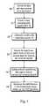
- FIG. 1is a flow chart illustrating one embodiment of the method of the invention.
- FIG. 2illustrates one embodiment of the apparatus of the invention.
- FIG. 1In the following section, one preferred embodiment of the present invention is shown. In this connection, reference is made to the flow chart shown in FIG. 1 .
- a mathematical SSS reconstruction of the measured datais performed.
- the reconstructionfinds out both the internal and external multi-pole components.
- the interferences in the intermediate space that were found outcan be filtered out using a mathematical operation.
- the datais divided into suitable periods of time 10 , which are processed separately.
- the periods of timeshall be of suitable length to ensure statistical reliability; and, for example, in the MEG, the length should be at least some tens of milliseconds.
- the lengthshould be at least some tens of milliseconds.
- the signals associated with period of time iare denoted with an N ⁇ n-dimensional matrix B i 11 , where N denotes the number of channels, and n is the number of samples, which can vary from one period of time to another.
- the length in time of the datais n/f s , where f s denotes the sampling frequency.
- each period of timeundergoes an SSS reconstruction.
- the signalsare trans-formed into an m ⁇ n-dimensional multi-pole component matrix 12 :
- X iS + B i , (2)
- S +is the pseudo inverse of the SSS basis matrix S.
- each period of timeis performed the Principal Component Analysis (PCA analysis) disclosed in the prior art in a time domain where from the data, the most significant signals 13 in the time domain are searched.
- PCA analysisis performed for signals of both the inside and outside, resulting in matrixes C in,i and C out,i , of which the former contains an n in,i number and the latter an n out,i number of n-dimensional PCA vectors, which are mutually orthogonal (i.e. independent of each other).
- the interference sources disposed in the intermediate spaceinevitably have a share in both the matrix C in,i and C out,i , whereas the internal signals only have components in the matrix C in,i , and correspondingly, the external signals only have components in the matrix C out,i .
- the desired vector set Ciis an intersection of the signal spaces to be compared. In this manner, the signals representing the interferences in the intermediate space are found out 14 . It must be noted that the number p of said vectors can vary from one period of time to another.
- the interference in the intermediate spacecan be eliminated 15 , for example, by performing in the time domain an SSP operation (Signal Space Projection), in which the internal signal vectors are in this case projected against the known interference sub-space, i.e. Ci to a perpendicular plane.
- SSP operationSignal Space Projection
- B idenotes a signal purified from interferences; P i is a projection operator; T denotes transpose and I denotes a unit matrix.
- One embodiment of the present inventioncomprises that in the calculation, the external signals B out,i are left out.
- One embodiment of the present inventioncomprises that the method utilises, in addition, the set of reference sensors.
- the actual measurement sensorsare disposed near the measurement object (e.g. a head), and farther, as seen from the measurement object, are disposed reference sensors that are only used to measure external big-amplitude interferences.
- the external signals B out,i or B res,ican be formed from the signals measured by the set of reference sensors.
- the external signals B out,i or B res,ican be formed from the signals measured by the set of reference sensors.
- One alternativeis then to compile the internal signals B in,i from the unprocessed signals measured by the actual signal sensors.
- PCAPrincipal Component Analysis
- FIG. 2is an example illustrating an MEG apparatus (magnetoencephalography) that can be used to measure a neuromagnetic signal.
- the deviceconsists of a sensor assembly 20 (including nine sensors in the example of the figure) surrounding the head of a person being monitored and of electronics 21 controlling the operation of the measuring device.
- the systemhas been illustrated as a simplified figure as seen from above.
- each sensor of the deviceis a small-sized feedback coil 22 , by means of which the control means 21 run the sensor 20 in a so-called flow-locked state.
- the voltage necessary to obtain this currentis the measurement signal given by the channel in question. All conventional MEG devices have been implemented according to this principle.
- the feedback coils 22are sensor-specific.
- the coilsare so small and so positioned that the field produced by them only causes an effect in the sensor of each coil's own.
- the interference sources disposed in the vicinity of the measurement region of the sensors 20function three electrodes 24 , which can act as the stimulator of the vagus nerve in the region of a patient's neck.
- the region of a patient's neckis considered to be included in the so-called intermediate space when the measuring sensors 20 are disposed about a patient's head 23 .
- the present inventionobserves interferences caused by electrodes 24 and filters them out from the signal measured by sensors 20 , in a manner as described above.
- One application of the present inventionincludes the use as a movement monitoring method. This can be implemented, for example, so that the outer surface of the head is provided with signal transmitters representing sources disposed in the intermediate space. These signal transmitters can be, for example, small coils. If the head is moving, then it shows as signals produced by these sources in the vector set C i . Thus, by examining the vector set it is possible to observe and model the movement.
- Another application of the present inventionis the use as a calibration algorithm.
- An inaccurate calibration of the measurement systemcauses erroneously signal components deviating from zero into the matrix C i , although there would not be any signal sources in the intermediate space.
- the devicecan be calibrated by setting the calibration parameters of the device to values by which the signal shown in the C i is minimised.
- the calibrationcan be performed in this manner provided that it is known that during the calibration measurement there are no sources in the intermediate space.
- the method of the present inventioncan be implemented as a computer program, a circuit solution or as a combination of these.
Landscapes
- Health & Medical Sciences (AREA)
- Physics & Mathematics (AREA)
- Life Sciences & Earth Sciences (AREA)
- Biomedical Technology (AREA)
- Medical Informatics (AREA)
- Biophysics (AREA)
- Pathology (AREA)
- Engineering & Computer Science (AREA)
- Condensed Matter Physics & Semiconductors (AREA)
- Heart & Thoracic Surgery (AREA)
- General Physics & Mathematics (AREA)
- Molecular Biology (AREA)
- Surgery (AREA)
- Animal Behavior & Ethology (AREA)
- General Health & Medical Sciences (AREA)
- Public Health (AREA)
- Veterinary Medicine (AREA)
- Measurement And Recording Of Electrical Phenomena And Electrical Characteristics Of The Living Body (AREA)
Abstract
Description
M=UΣV* (1)
Xi=S+Bi, (2)
Xi=[Xin,iXout,i] (3)
Bin,i=SinXin,i (4)
Bout,i=SoutXout,i (5)
Bi=[PiBin,iT]T (6)
and
Pi=I−CiCiT (7)
where Bidenotes a signal purified from interferences; Piis a projection operator; T denotes transpose and I denotes a unit matrix.
Bres,i=Bi−(Bin,i+Bout,i) (8)
Bres,i=Bi−Bin,i (9)
Claims (26)
Applications Claiming Priority (3)
| Application Number | Priority Date | Filing Date | Title |
|---|---|---|---|
| FI20050445 | 2005-04-28 | ||
| FI20050445AFI119133B (en) | 2005-04-28 | 2005-04-28 | Method and apparatus for eliminating interference during electromagnetic multichannel measurement |
| PCT/FI2006/000127WO2006114473A1 (en) | 2005-04-28 | 2006-04-21 | Method and device for interference suppression in electromagnetic multi-channel measurement |
Publications (2)
| Publication Number | Publication Date |
|---|---|
| US20080294386A1 US20080294386A1 (en) | 2008-11-27 |
| US7933727B2true US7933727B2 (en) | 2011-04-26 |
Family
ID=34508130
Family Applications (1)
| Application Number | Title | Priority Date | Filing Date |
|---|---|---|---|
| US11/912,764Active2026-11-25US7933727B2 (en) | 2005-04-28 | 2006-04-21 | Method and device for interference suppression in electromagnetic multi-channel measurement |
Country Status (6)
| Country | Link |
|---|---|
| US (1) | US7933727B2 (en) |
| EP (1) | EP1880226B1 (en) |
| JP (1) | JP4875696B2 (en) |
| CA (1) | CA2606959C (en) |
| FI (1) | FI119133B (en) |
| WO (1) | WO2006114473A1 (en) |
Cited By (11)
| Publication number | Priority date | Publication date | Assignee | Title |
|---|---|---|---|---|
| US20110156700A1 (en)* | 2009-12-31 | 2011-06-30 | Itay Kariv | System and method for assessing interference to a signal caused by a magnetic field |
| WO2013040497A3 (en)* | 2011-09-15 | 2013-05-10 | University Of Washington Through Its Center For Commercialization | Systems and methods for sensing environmental changes using light sources as sensors |
| US20170212161A1 (en)* | 2016-01-21 | 2017-07-27 | Qinetiq Limited | System and process |
| WO2017205734A1 (en)* | 2016-05-26 | 2017-11-30 | University Of Washington | Reducing sensor noise in multichannel arrays using oversampled temporal projection and associated systems and methods |
| US11273283B2 (en) | 2017-12-31 | 2022-03-15 | Neuroenhancement Lab, LLC | Method and apparatus for neuroenhancement to enhance emotional response |
| US11364361B2 (en) | 2018-04-20 | 2022-06-21 | Neuroenhancement Lab, LLC | System and method for inducing sleep by transplanting mental states |
| US11452839B2 (en) | 2018-09-14 | 2022-09-27 | Neuroenhancement Lab, LLC | System and method of improving sleep |
| US11717686B2 (en) | 2017-12-04 | 2023-08-08 | Neuroenhancement Lab, LLC | Method and apparatus for neuroenhancement to facilitate learning and performance |
| US11723579B2 (en) | 2017-09-19 | 2023-08-15 | Neuroenhancement Lab, LLC | Method and apparatus for neuroenhancement |
| US11786694B2 (en) | 2019-05-24 | 2023-10-17 | NeuroLight, Inc. | Device, method, and app for facilitating sleep |
| US12280219B2 (en) | 2017-12-31 | 2025-04-22 | NeuroLight, Inc. | Method and apparatus for neuroenhancement to enhance emotional response |
Families Citing this family (20)
| Publication number | Priority date | Publication date | Assignee | Title |
|---|---|---|---|---|
| JP5361131B2 (en) | 2007-01-03 | 2013-12-04 | エレクタ アクチボラゲット | Analysis of multi-channel measurement data using orthogonal virtual channels |
| KR101047131B1 (en) | 2008-12-29 | 2011-07-06 | 한국항공우주연구원 | Automatic generation device for calibration data of multi-channel signal control circuit |
| FI124019B (en)* | 2010-03-26 | 2014-02-14 | Elekta Ab | Method of designing coil systems to form magnetic fields of desired geometry |
| FI124427B (en)* | 2010-07-06 | 2014-08-29 | Elekta Ab | Procedure for precise interference space in biomagnetic field measurements |
| CN105212895B (en)* | 2015-08-24 | 2019-01-15 | 中国科学院苏州生物医学工程技术研究所 | Dynamic brain source localization method |
| US11051737B2 (en) | 2017-05-19 | 2021-07-06 | Ricoh Company, Ltd. | Biomagnetic measurement method, biomagnetic measuring device, and biomagnetic measuring system |
| JP6996135B2 (en) | 2017-07-03 | 2022-01-17 | 株式会社リコー | Information processing equipment, information processing methods, and programs |
| WO2020040168A1 (en) | 2018-08-22 | 2020-02-27 | 旭化成エレクトロニクス株式会社 | Magnetic field measurement device, magnetic field measurement method, and magnetic field measurement program |
| JP6936405B2 (en) | 2018-12-26 | 2021-09-15 | 旭化成エレクトロニクス株式会社 | Magnetic field measuring device |
| US11497425B2 (en) | 2019-03-08 | 2022-11-15 | Asahi Kasei Microdevices Corporation | Magnetic field measurement apparatus |
| US11768258B2 (en) | 2019-11-27 | 2023-09-26 | Ricoh Company, Ltd. | Signal separating apparatus, signal separating method, and non-transitory recording medium |
| US11454679B2 (en) | 2020-01-20 | 2022-09-27 | Asahi Kasei Microdevices Corporation | Magnetic field measuring apparatus, magnetic field measuring method and recording medium with magnetic field measuring program recorded thereon |
| JP7525297B2 (en) | 2020-05-08 | 2024-07-30 | 旭化成エレクトロニクス株式会社 | Magnetic field measurement device, magnetic field measurement method, and magnetic field measurement program |
| WO2021242680A1 (en)* | 2020-05-28 | 2021-12-02 | Hi Llc | Systems and methods for recording neural activity |
| WO2021242682A1 (en)* | 2020-05-28 | 2021-12-02 | Hi Llc | Systems and methods for recording biomagnetic fields of the human heart |
| JP7626622B2 (en) | 2021-01-20 | 2025-02-04 | 旭化成エレクトロニクス株式会社 | Magnetic field measurement device, magnetic field measurement method, magnetic field measurement program |
| CN113589051A (en)* | 2021-08-04 | 2021-11-02 | 西安电子科技大学 | Clutter suppression field electromagnetic measurement device and method |
| CA3230254A1 (en) | 2021-08-31 | 2023-03-09 | Evolv Technologies, Inc. | Suppression of interference in threat detection |
| CN115018018B (en)* | 2022-08-05 | 2022-11-11 | 北京航空航天大学杭州创新研究院 | Double spatial filtering method for inhibiting background noise |
| JP2025074529A (en) | 2023-10-30 | 2025-05-14 | Tdk株式会社 | Measurement equipment |
Citations (11)
| Publication number | Priority date | Publication date | Assignee | Title |
|---|---|---|---|---|
| EP0966689A1 (en) | 1997-03-10 | 1999-12-29 | The Secretary Of State For Defence | Magnetic gradiometer |
| US6195576B1 (en)* | 1998-03-09 | 2001-02-27 | New York University | Quantitative magnetoencephalogram system and method |
| US20030032889A1 (en) | 2001-06-18 | 2003-02-13 | Neurometrix, Inc. | Method and apparatus for identifying constituent signal components from a plurality of evoked physiological composite signals |
| US6544170B1 (en) | 1999-06-21 | 2003-04-08 | Shimadzu Corporation | Biosignal measuring method and apparatus |
| WO2004081595A1 (en) | 2003-03-14 | 2004-09-23 | Elekta Neuromag Oy | Method and system for processing a multi-channel measurement of magnetic fields |
| US20050055175A1 (en) | 2003-09-10 | 2005-03-10 | Jahns Gary L. | Industrial process fault detection using principal component analysis |
| US20050056140A1 (en) | 2003-06-02 | 2005-03-17 | Nam-Ik Cho | Apparatus and method for separating music and voice using independent component analysis algorithm for two-dimensional forward network |
| WO2005078467A1 (en) | 2004-02-13 | 2005-08-25 | Elekta Ab (Publ) | A method for interference suppression in a measuring device |
| US20050240642A1 (en)* | 1998-11-12 | 2005-10-27 | Parra Lucas C | Method and system for on-line blind source separation |
| US7254500B2 (en)* | 2003-03-31 | 2007-08-07 | The Salk Institute For Biological Studies | Monitoring and representing complex signals |
| US7263467B2 (en)* | 2002-09-30 | 2007-08-28 | University Of Florida Research Foundation Inc. | Multi-dimensional multi-parameter time series processing for seizure warning and prediction |
Family Cites Families (2)
| Publication number | Priority date | Publication date | Assignee | Title |
|---|---|---|---|---|
| US4913152A (en) | 1988-04-28 | 1990-04-03 | The Johns Hopkins University | Magnetoencephalograph (MEG) using a multi-axis magnetic gradiometer for localization and tracking of neuromagnetic signals |
| US5513649A (en)* | 1994-03-22 | 1996-05-07 | Sam Technology, Inc. | Adaptive interference canceler for EEG movement and eye artifacts |
- 2005
- 2005-04-28FIFI20050445Apatent/FI119133B/enactive
- 2006
- 2006-04-21JPJP2008508241Apatent/JP4875696B2/enactiveActive
- 2006-04-21EPEP06725888.9Apatent/EP1880226B1/enactiveActive
- 2006-04-21USUS11/912,764patent/US7933727B2/enactiveActive
- 2006-04-21CACA2606959Apatent/CA2606959C/enactiveActive
- 2006-04-21WOPCT/FI2006/000127patent/WO2006114473A1/enactiveApplication Filing
Patent Citations (11)
| Publication number | Priority date | Publication date | Assignee | Title |
|---|---|---|---|---|
| EP0966689A1 (en) | 1997-03-10 | 1999-12-29 | The Secretary Of State For Defence | Magnetic gradiometer |
| US6195576B1 (en)* | 1998-03-09 | 2001-02-27 | New York University | Quantitative magnetoencephalogram system and method |
| US20050240642A1 (en)* | 1998-11-12 | 2005-10-27 | Parra Lucas C | Method and system for on-line blind source separation |
| US6544170B1 (en) | 1999-06-21 | 2003-04-08 | Shimadzu Corporation | Biosignal measuring method and apparatus |
| US20030032889A1 (en) | 2001-06-18 | 2003-02-13 | Neurometrix, Inc. | Method and apparatus for identifying constituent signal components from a plurality of evoked physiological composite signals |
| US7263467B2 (en)* | 2002-09-30 | 2007-08-28 | University Of Florida Research Foundation Inc. | Multi-dimensional multi-parameter time series processing for seizure warning and prediction |
| WO2004081595A1 (en) | 2003-03-14 | 2004-09-23 | Elekta Neuromag Oy | Method and system for processing a multi-channel measurement of magnetic fields |
| US7254500B2 (en)* | 2003-03-31 | 2007-08-07 | The Salk Institute For Biological Studies | Monitoring and representing complex signals |
| US20050056140A1 (en) | 2003-06-02 | 2005-03-17 | Nam-Ik Cho | Apparatus and method for separating music and voice using independent component analysis algorithm for two-dimensional forward network |
| US20050055175A1 (en) | 2003-09-10 | 2005-03-10 | Jahns Gary L. | Industrial process fault detection using principal component analysis |
| WO2005078467A1 (en) | 2004-02-13 | 2005-08-25 | Elekta Ab (Publ) | A method for interference suppression in a measuring device |
Non-Patent Citations (8)
| Title |
|---|
| Binnie, ":Vagus Nerve Stimulation for Epilepsy: a Review" Seizure, vol. 9, pp. 161-169, 2000. |
| Diekmann et al., RF-SQUID to DC-SQUID Upgrade of a 28-Channel Magnetoencephalography (MEG) System, Jan. 11, 1996, Measuring Science Technology, vol. 7, pp. 845-852.* |
| Kajola et al., Presentation of Electromagnetic Multichannel Data: The Signal Space Separation Method, Jun. 21, 2005, Journal of Applied Physics, pp. 1-9.* |
| Taula et al., Suppression of Interference and Artifacts by the Signal Space Separation Method, Brain Topography, vol. 16, No. 4, pp. 269-275, 2004. |
| Taulu et al., Clinical Applications of the Signal Space Separation Method, Aug. 2004, Elsevier B.V., pp. 32-37.* |
| Tonoike et al., Noise Reduction on the Olfactory Neuromagnetic Measurements Using SSP Method, 2001, Osoka National Research Institute, pp. 1-4.* |
| Tonoike et al., Olfactory Cognitive Response Using Odorant Odd-Ball Paradigm by Magnetoencephalography, Sep. 23, 2003, Journal of Temporal Design in Architecture and the Environment, vol. 3, pp. 43-53.* |
| Volegov et al., Noise-Free Magnetoencephalography Recordings of Brain Function, May 4, 2004, Institute of Physics Publishing, pp. 2117-2127.* |
Cited By (19)
| Publication number | Priority date | Publication date | Assignee | Title |
|---|---|---|---|---|
| US8600480B2 (en)* | 2009-12-31 | 2013-12-03 | Mediguide Ltd. | System and method for assessing interference to a signal caused by a magnetic field |
| US20110156700A1 (en)* | 2009-12-31 | 2011-06-30 | Itay Kariv | System and method for assessing interference to a signal caused by a magnetic field |
| WO2013040497A3 (en)* | 2011-09-15 | 2013-05-10 | University Of Washington Through Its Center For Commercialization | Systems and methods for sensing environmental changes using light sources as sensors |
| US9618553B2 (en) | 2011-09-15 | 2017-04-11 | University Of Washington Through Its Center For Commercialization | Systems and methods for sensing environmental changes using light sources as sensors |
| US10101376B2 (en)* | 2016-01-21 | 2018-10-16 | Qinetiq Limited | System and process |
| US20170212161A1 (en)* | 2016-01-21 | 2017-07-27 | Qinetiq Limited | System and process |
| US11540778B2 (en) | 2016-05-26 | 2023-01-03 | University Of Washington | Reducing sensor noise in multichannel arrays using oversampled temporal projection and associated systems and methods |
| WO2017205734A1 (en)* | 2016-05-26 | 2017-11-30 | University Of Washington | Reducing sensor noise in multichannel arrays using oversampled temporal projection and associated systems and methods |
| US11723579B2 (en) | 2017-09-19 | 2023-08-15 | Neuroenhancement Lab, LLC | Method and apparatus for neuroenhancement |
| US11717686B2 (en) | 2017-12-04 | 2023-08-08 | Neuroenhancement Lab, LLC | Method and apparatus for neuroenhancement to facilitate learning and performance |
| US11273283B2 (en) | 2017-12-31 | 2022-03-15 | Neuroenhancement Lab, LLC | Method and apparatus for neuroenhancement to enhance emotional response |
| US11318277B2 (en) | 2017-12-31 | 2022-05-03 | Neuroenhancement Lab, LLC | Method and apparatus for neuroenhancement to enhance emotional response |
| US11478603B2 (en) | 2017-12-31 | 2022-10-25 | Neuroenhancement Lab, LLC | Method and apparatus for neuroenhancement to enhance emotional response |
| US12280219B2 (en) | 2017-12-31 | 2025-04-22 | NeuroLight, Inc. | Method and apparatus for neuroenhancement to enhance emotional response |
| US12383696B2 (en) | 2017-12-31 | 2025-08-12 | NeuroLight, Inc. | Method and apparatus for neuroenhancement to enhance emotional response |
| US12397128B2 (en) | 2017-12-31 | 2025-08-26 | NeuroLight, Inc. | Method and apparatus for neuroenhancement to enhance emotional response |
| US11364361B2 (en) | 2018-04-20 | 2022-06-21 | Neuroenhancement Lab, LLC | System and method for inducing sleep by transplanting mental states |
| US11452839B2 (en) | 2018-09-14 | 2022-09-27 | Neuroenhancement Lab, LLC | System and method of improving sleep |
| US11786694B2 (en) | 2019-05-24 | 2023-10-17 | NeuroLight, Inc. | Device, method, and app for facilitating sleep |
Also Published As
| Publication number | Publication date |
|---|---|
| FI119133B (en) | 2008-07-31 |
| US20080294386A1 (en) | 2008-11-27 |
| EP1880226A1 (en) | 2008-01-23 |
| JP2008538956A (en) | 2008-11-13 |
| CA2606959A1 (en) | 2006-11-02 |
| EP1880226A4 (en) | 2014-11-05 |
| EP1880226B1 (en) | 2018-11-28 |
| FI20050445A0 (en) | 2005-04-28 |
| WO2006114473A1 (en) | 2006-11-02 |
| JP4875696B2 (en) | 2012-02-15 |
| CA2606959C (en) | 2017-01-24 |
| FI20050445L (en) | 2006-10-29 |
Similar Documents
| Publication | Publication Date | Title |
|---|---|---|
| US7933727B2 (en) | Method and device for interference suppression in electromagnetic multi-channel measurement | |
| US10307105B2 (en) | Method and device for recognizing and removing undesired artifacts in multichannel magnetic field or electric potential measurements | |
| US8838225B2 (en) | Analysis of multi-channel measurement data using orthogonal virtual channels | |
| US7463024B2 (en) | Method and device for processing a multi-channel measurement of magnetic fields | |
| EP2591375B1 (en) | Method for adjusting interference signal space in bio-magnetic field measurements | |
| WO2020214771A1 (en) | Systems and methods for suppression of interferences in magnetoencephalography (meg) and other magnetometer measurements | |
| US9370309B2 (en) | Magnetoencephalography system and method for 3D localization and tracking of electrical activity in brain | |
| CA2556335A1 (en) | A method for interference suppression in a measuring device | |
| Helle et al. | Extended signal-space separation method for improved interference suppression in MEG | |
| EP0477434A1 (en) | Analysis of biological signals using data from arrays of sensors | |
| Zhang et al. | Source localization with MEG data: A beamforming approach based on covariance thresholding | |
| CN115245334B (en) | Magnetic field noise elimination method based on limb movement analysis | |
| Qiu et al. | A real-time signal space separation method for a 32-channel planar sensor array | |
| KR100583767B1 (en) | How to remove fake signals in signal processing of multichannel stimuli induced brain | |
| Alho | Automated quantitative analysis of MCC-IMS spectra | |
| Huang et al. | Partially adaptive STAP for fMRI: a method for detecting brain activation regions in simulation and human data |
Legal Events
| Date | Code | Title | Description |
|---|---|---|---|
| AS | Assignment | Owner name:ELECKTA AB (PUBL.), SWEDEN Free format text:ASSIGNMENT OF ASSIGNORS INTEREST;ASSIGNORS:TAULU, SAMU;SIMOLA, JUHA;REEL/FRAME:021142/0506 Effective date:20080618 | |
| STCF | Information on status: patent grant | Free format text:PATENTED CASE | |
| FPAY | Fee payment | Year of fee payment:4 | |
| MAFP | Maintenance fee payment | Free format text:PAYMENT OF MAINTENANCE FEE, 8TH YEAR, LARGE ENTITY (ORIGINAL EVENT CODE: M1552); ENTITY STATUS OF PATENT OWNER: LARGE ENTITY Year of fee payment:8 | |
| AS | Assignment | Owner name:ELEKTA OY, FINLAND Free format text:ASSIGNMENT OF ASSIGNORS INTEREST;ASSIGNOR:ELEKTA AB (PUBL);REEL/FRAME:049249/0624 Effective date:20180711 | |
| AS | Assignment | Owner name:MEGIN OY, FINLAND Free format text:CHANGE OF NAME;ASSIGNOR:ELEKTA OY;REEL/FRAME:049669/0662 Effective date:20190605 | |
| MAFP | Maintenance fee payment | Free format text:PAYMENT OF MAINTENANCE FEE, 12TH YEAR, LARGE ENTITY (ORIGINAL EVENT CODE: M1553); ENTITY STATUS OF PATENT OWNER: LARGE ENTITY Year of fee payment:12 |