US7933642B2 - Wireless ECG system - Google Patents
Wireless ECG systemDownload PDFInfo
- Publication number
- US7933642B2 US7933642B2US10/439,356US43935603AUS7933642B2US 7933642 B2US7933642 B2US 7933642B2US 43935603 AUS43935603 AUS 43935603AUS 7933642 B2US7933642 B2US 7933642B2
- Authority
- US
- United States
- Prior art keywords
- electrode
- electronics unit
- base station
- body electronics
- chest assembly
- Prior art date
- Legal status (The legal status is an assumption and is not a legal conclusion. Google has not performed a legal analysis and makes no representation as to the accuracy of the status listed.)
- Expired - Fee Related
Links
Images


Classifications
- A—HUMAN NECESSITIES
- A61—MEDICAL OR VETERINARY SCIENCE; HYGIENE
- A61B—DIAGNOSIS; SURGERY; IDENTIFICATION
- A61B5/00—Measuring for diagnostic purposes; Identification of persons
- A61B5/68—Arrangements of detecting, measuring or recording means, e.g. sensors, in relation to patient
- A61B5/6801—Arrangements of detecting, measuring or recording means, e.g. sensors, in relation to patient specially adapted to be attached to or worn on the body surface
- A61B5/684—Indicating the position of the sensor on the body
- A61B5/6841—Indicating the position of the sensor on the body by using templates
- A—HUMAN NECESSITIES
- A61—MEDICAL OR VETERINARY SCIENCE; HYGIENE
- A61B—DIAGNOSIS; SURGERY; IDENTIFICATION
- A61B5/00—Measuring for diagnostic purposes; Identification of persons
- A61B5/0002—Remote monitoring of patients using telemetry, e.g. transmission of vital signals via a communication network
- A61B5/0004—Remote monitoring of patients using telemetry, e.g. transmission of vital signals via a communication network characterised by the type of physiological signal transmitted
- A61B5/0006—ECG or EEG signals
- A—HUMAN NECESSITIES
- A61—MEDICAL OR VETERINARY SCIENCE; HYGIENE
- A61B—DIAGNOSIS; SURGERY; IDENTIFICATION
- A61B5/00—Measuring for diagnostic purposes; Identification of persons
- A61B5/24—Detecting, measuring or recording bioelectric or biomagnetic signals of the body or parts thereof
- A61B5/25—Bioelectric electrodes therefor
- A61B5/251—Means for maintaining electrode contact with the body
- A61B5/257—Means for maintaining electrode contact with the body using adhesive means, e.g. adhesive pads or tapes
- A61B5/259—Means for maintaining electrode contact with the body using adhesive means, e.g. adhesive pads or tapes using conductive adhesive means, e.g. gels
- A—HUMAN NECESSITIES
- A61—MEDICAL OR VETERINARY SCIENCE; HYGIENE
- A61B—DIAGNOSIS; SURGERY; IDENTIFICATION
- A61B5/00—Measuring for diagnostic purposes; Identification of persons
- A61B5/24—Detecting, measuring or recording bioelectric or biomagnetic signals of the body or parts thereof
- A61B5/25—Bioelectric electrodes therefor
- A61B5/279—Bioelectric electrodes therefor specially adapted for particular uses
- A61B5/28—Bioelectric electrodes therefor specially adapted for particular uses for electrocardiography [ECG]
- A61B5/282—Holders for multiple electrodes
- A—HUMAN NECESSITIES
- A61—MEDICAL OR VETERINARY SCIENCE; HYGIENE
- A61B—DIAGNOSIS; SURGERY; IDENTIFICATION
- A61B2562/00—Details of sensors; Constructional details of sensor housings or probes; Accessories for sensors
- A61B2562/08—Sensors provided with means for identification, e.g. barcodes or memory chips
- A—HUMAN NECESSITIES
- A61—MEDICAL OR VETERINARY SCIENCE; HYGIENE
- A61B—DIAGNOSIS; SURGERY; IDENTIFICATION
- A61B2562/00—Details of sensors; Constructional details of sensor housings or probes; Accessories for sensors
- A61B2562/16—Details of sensor housings or probes; Details of structural supports for sensors
- A61B2562/17—Comprising radiolucent components
- A—HUMAN NECESSITIES
- A61—MEDICAL OR VETERINARY SCIENCE; HYGIENE
- A61B—DIAGNOSIS; SURGERY; IDENTIFICATION
- A61B5/00—Measuring for diagnostic purposes; Identification of persons
- A61B5/24—Detecting, measuring or recording bioelectric or biomagnetic signals of the body or parts thereof
- A61B5/25—Bioelectric electrodes therefor
- A61B5/271—Arrangements of electrodes with cords, cables or leads, e.g. single leads or patient cord assemblies
- A61B5/273—Connection of cords, cables or leads to electrodes
- A61B5/274—Connection of cords, cables or leads to electrodes using snap or button fasteners
- A—HUMAN NECESSITIES
- A61—MEDICAL OR VETERINARY SCIENCE; HYGIENE
- A61B—DIAGNOSIS; SURGERY; IDENTIFICATION
- A61B5/00—Measuring for diagnostic purposes; Identification of persons
- A61B5/24—Detecting, measuring or recording bioelectric or biomagnetic signals of the body or parts thereof
- A61B5/25—Bioelectric electrodes therefor
- A61B5/276—Protection against electrode failure
- A—HUMAN NECESSITIES
- A61—MEDICAL OR VETERINARY SCIENCE; HYGIENE
- A61B—DIAGNOSIS; SURGERY; IDENTIFICATION
- A61B5/00—Measuring for diagnostic purposes; Identification of persons
- A61B5/72—Signal processing specially adapted for physiological signals or for diagnostic purposes
- A61B5/7232—Signal processing specially adapted for physiological signals or for diagnostic purposes involving compression of the physiological signal, e.g. to extend the signal recording period
Definitions
- the present inventionrelates to a wireless monitoring system and, more particularly, to a wireless monitoring system for monitoring physiological data.
- An electrocardiograph (ECG) systemmonitors heart electrical activity in a patient.
- ECG systemsutilize electrodes or sensors placed on a patient in specific locations to detect electrical impulses generated by the heart during each beat. Typically, these electrical impulses or signals are detected by and directly transferred from the sensors or electrodes to a stationary ECG monitor via multiple cables or wires.
- the ECG monitorperforms various signal processing and computational operations to convert the raw electrical signals into meaningful information that can be displayed on a monitor or printed out for review by a physician.
- portions of the conventional electrodes or sensors that connect to the cables, wires, or chest assembliesare not standardized.
- the metal snap pieces or metal tabs that connect to the female portions of the cables, wires, or chest assembliescome in various sizes, shapes and configurations. Accordingly, many of the conventional electrodes or sensors are not compatible for use with many of the wires, leads, or chest assemblies used in physiological data collections systems.
- some wireless or telemetry systemsuse chest assemblies having integrated electrodes or sensors.
- a major disadvantage to such chest assembliesis that those chest assemblies must be hermetically packaged to preserve the integrity of the aqueous silver chloride gel on the electrodes integrally connected to those chest assemblies.
- the cost of such chest assembliesis significant. Because those chest assemblies are designed to be disposed of after each patient use, the increased cost of those chest assemblies make them cost inefficient.
- the spring loaded, female snap pieces and the metal snaps typically used with conventional electrodes or sensorare typically constructed of metal and are not radiolucent. Consequently, those snap pieces and metal snaps show up clearly on x-rays and other imaging procedures. Transparency to hospital imaging systems such as x-ray or fluoroscopes is desirable in many medical procedures such as are carried out in cardiac catheterization labs where conventional electrocardiograph electrodes and wires may obscure the view of internal blood vessels.
- Radiolucent electrodesare known in the art and are sold by companies such as Kendle and 3M. Non-disposable radiolucent electrode leads exist but cost in excess of a thousand dollars per radiolucent lead set.
- the present inventionrelates to a wireless ECG system that is universally compatible with existing or conventional ECG monitors.
- the ECG systemgenerally comprises a chest assembly, a body electronics unit, and a base station.
- the chest assemblyconnects to electrodes specifically located on a patient's body for detecting electrical signals from the patient's heart.
- the electrical signalsare detected by the chest assembly—thus, providing up to a “7 lead” analysis of the heart.
- the chest assemblycan be augmented with a precordial assembly that connects to electrodes specifically located on the patient's body—thus, providing a “12 lead” analysis of the heart.
- the electrical signalsare transmitted through the chest assembly and/or the precordial assembly to the body electronics unit, which removably secures to the patient via an armband.
- the body electronics unittransmits the electrical signals to the base station via radio transmission.
- the base stationcontains terminals configured to attach to standard lead wires or cable.
- the base stationtransmits the electrical signals to a conventional ECG monitor via the standard lead wires or cables.
- the ECG monitorprocesses or transforms the electrical signals into meaningful information that can be displayed on the ECG monitor for review by a physician.
- the ECG systemeliminates the wires that ordinarily tether an ECG patent to an ECG monitor by replacing conventional wires with a radio link.
- the present inventionis lightweight and portable—thereby providing increased comfort and mobility to the patient.
- the present inventionrequires decreased setup times and is more convenient for health practitioners to use than conventional ECG systems.
- the present inventionis capable of collecting and transmitting other physiological data.
- the body electronics unitis capable of transmitting and the base station is capable of receiving and processing physiological data pertaining to a patient's pulse, respiration rate, heart rate, temperature, blood pressure, EEG signals, and pulse oximeter signals, or the like.
- the present inventionrelates to a fastener assembly for a connecting a conventional electrode or sensor to a system for collecting physiological data from a patient. More particularly, the fastener assembly electrically connects the conventional electrode or sensor to an electrically conductive element or trace within the lead assembly.
- the electrically conductive elementmay be silver epoxy or any other suitable electrically conductive adhesive.
- the fastener assemblyconnects the electrodes or sensors to the electrically conductive element or trace at an electrode connection point.
- the lead assemblyhas an aperture therethrough formed from a star cut pattern. The star cut pattern could be die cut, punched, laser cut or formed by other known means.
- the star cut patterndefines flaps that mechanically hold the electrode or sensor in the aperture and provide an electrical connection between the electrically conductive element or trace and the electrode or sensor upon insertion of the electrode or sensor in the aperture.
- the fastener assemblyincludes an electrode housing secured to the non-patient side of the lead assembly.
- the electrode housingis constructed of an elastomeric material bonded to the back surface of the lead assembly and contains a female void for receiving and removably securing a male portion of the electrode or sensor.
- the chest assemblymay optionally include an electrically conductive, adhesive layer for removably securing the electrode or sensor to the chest assembly and providing enhanced electrical connection between the electrically conductive element or trace and the electrode or sensor upon insertion of the electrode or sensor though the aperture.
- the male portion of the electrode or sensoris inserted through the aperture starting at the patient side of the lead assembly.
- the flaps formed by the apertureare deflected as the male portion of the electrode or sensor is inserted into the aperture.
- the resilience of the flapscause the flaps to wipe against the male portion and mechanically hold the electrode or sensor in the aperture defined between the flaps.
- the male portionis inserted into the female void contained in the electrode housing.
- the female voidreceives the male portion of the electrode or sensor and removably secures the electrode or sensor to the chest assembly.
- the elastomeric property of the electrode housingallows the female void to receive and secure electrodes or sensor having different shapes and sizes.
- the electrode or sensoris inserted into the aperture until the contact portion of the electrode or sensor (such as a male snap post) abuts or contacts the electrically conductive element in the lead assembly.
- the electrically conductive element in the lead assemblymakes contact with the electrode or sensor and creates an electrical link between the electrode or sensor and the electrically conductive element or trace in the lead assembly.
- electrically conductive adhesivesmay be added to either the lead assembly or the electrode housing to enhance the electrical connection.
- the fastener assembly of the present inventionmay be used to connect conventional electrodes or sensors to both traditional wired systems and wireless systems for collecting physiological data from a patient.
- FIG. 1is a perspective view of an exemplary embodiment of the ECG system
- FIG. 2is a cross sectional view of the chest assembly and the precordial assembly
- FIG. 2Ais a cross sectional view of an exemplary embodiment of the chest assembly
- FIG. 3is a top view of an exemplary embodiment of the chest assembly
- FIG. 3Adepicts another exemplary embodiment of the chest assembly and the precordial assembly
- FIG. 4is a top view of an exemplary embodiment of the precordial assembly
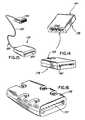
- FIG. 5is a perspective view of an exemplary embodiment of the body electronics unit
- FIG. 6is a top view an exemplary embodiment of the assembly connectors
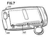
- FIG. 7is a perspective view of an exemplary embodiment of the body electronics unit
- FIG. 7Ais an exemplary embodiment of the user interface of the electronics body unit
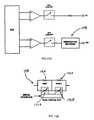
- FIG. 7Bis a block diagram of an exemplary of the respiration rate input circuit
- FIG. 7Cis a block diagram of an exemplary embodiment of the current source circuit
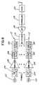
- FIG. 8is a block diagram of an exemplary embodiment of the transmitter
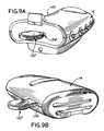
- FIG. 9Ais a perspective view of an exemplary embodiment of the base station used in conjunction with the token key
- FIG. 9Bdepicts the body electronics unit used in conjunction with the token key
- FIG. 10is a perspective view of an exemplary embodiment of the base station
- FIG. 11is a perspective view of an exemplary embodiment of the base station
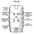
- FIG. 11Ais an exemplary embodiment of the user interface of the base station
- FIG. 12is a block diagram of an exemplary embodiment of the receiver
- FIG. 12Ais a block diagram of an exemplary embodiment of the respiration rate input circuit
- FIG. 12Bis a block diagram of an exemplary embodiment of the respiration rate network
- FIG. 13is a perspective view of an exemplary embodiment of the base station
- FIG. 14is an exemplary embodiment of the adaptor assembly
- FIG. 15is another exemplary embodiment of the adaptor assembly
- FIG. 16is another exemplary embodiment of the adaptor assembly
- FIG. 17is a flow chart of an exemplary embodiment for operation of the ECG system
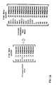
- FIG. 18depicts the order and timing in which the body electronics unit samples the signal channels
- FIG. 19depicts the formation of the raw data set and the snapshot data set after sampling the signal channels
- FIG. 20depicts the averaging process for the raw data set before transmission of the data set to the base station
- FIG. 21depicts the filtering process for the raw data set conducted after the averaging process and before transmission of the data set to the base station;
- FIG. 22depicts the raw data set and the snapshot data set packaged into raw data packets and snapshot data packets
- FIG. 23depicts the FIR interpolation process for the ECG data packets
- FIG. 24depicts the duplication process conducted after the FIR interpolation process
- FIG. 25depicts the restoration of the pacemaker pulse in the ECG data stream
- FIG. 26depicts the order and timing in which the base station plays out the signal channels
- FIG. 27is a block diagram of the BLUETOOTH air interface radio system used with the present invention.
- FIG. 28is a cross sectional view of an exemplary embodiment of chest assembly having an electrode housing
- FIG. 29is a cross sectional view of an exemplary embodiment of chest assembly having an electrode housing and coupled to an electrode;
- FIG. 30is a cross sectional view of another exemplary embodiment of chest assembly having an electrode housing and coupled to an electrode;
- FIG. 31is a cross sectional view of another exemplary embodiment of chest assembly having an electrode housing and coupled to an electrode;
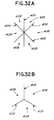
- FIGS. 32A-Edepict exemplary embodiments of an aperture formed in a chest assembly for receiving an electrode.
- the present inventionrelates to a wireless, portable ECG system.
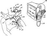
- the ECG system 10comprises a chest assembly 12 , a body electronics unit 14 , and a base station 16 .
- the chest assembly 12is a one-piece flexible circuit that connects a plurality of electrode connectors 18 .
- the electrode connectors 18are configured to connect to electrodes 20 or electrically conductive adhesives.
- the electrode connectors 18have snap terminals that connect to electrodes 20 having snap terminals.
- Each electrode connector 18connects to an electrically conductive element or trace for transmitting electrical signals.
- the electrically conductive elements or tracesrun along the chest assembly 12 and connect to a chest assembly connector 21 .
- the chest assembly 12may be constructed with electrode conductors, instead of electrode connectors.
- each electrode conductorwill have a flat, conductive surface. Electrodes having flat conductive surfaces may be coupled to the electrode conductors via a suitable adhesive. Thus, electrodes can be attached to the chest assembly by “sticking” an electrode to each electrode conductor.
- the chest assembly 12may have outer layers 22 , 24 that are constructed of a lightweight and reasonably moisture resistant material, such as DuPont Sontara® or other suitable fabric.
- the chest assembly 12may be constructed with only one outer layer or no outer layers without departing from the spirit and scope of the invention. Moreover, if the chest assembly is constructed with just one outer layer, that outer layer can be on either side of the chest assembly 12 without departing from the spirit and scope of the invention.
- Adhesive layers 26 , 28secure insulating layers 30 , 32 to the outer layers 22 , 24 respectively. Insulating layers 30 , 32 may be constructed of Mylar® (polyester) film or other suitable insulating material.
- Adhesive layers 34 , 36secure the insulating layers 30 , 32 to a base layer 38 .
- the base layer 38is preferably constructed of Mylar film and has a first side 40 and a second side 42 .
- the electrically conductive elements or traces that connect to the electrode connectors 18may be located on the first side 40 of the base layer 38 .
- One such conductive element or traceis shown at 39 .
- a shielding layer 44 for reducing any external inferences or radio frequency noise with the chest assembly 12may be located on the second side 42 of the base layer 38 .
- the shielding layer 44may be constructed of single or multiple layers of dielectric, or electrically or magnetically conductive material.
- the chest assembly 12may be constructed without a shielding layer 44 without departing from the spirit and scope of the invention.
- a shielding layer 44will be necessary in “noisy” environments.
- the shielding layerpreferably comprises an X-patterned grid.
- the back of the electrode connector 18may also be covered with Mylar to further insulate the chest assembly 12 and prevent an externally applied electric potential from entering the ECG system.
- the chest assembly 12may be constructed with an adhesive sheet 45 that partially or completely covers the chest assembly 12 .
- the electrode connectors 18may be sandwiched between the adhesive sheet 45 and the outer layer 24 of the chest assembly 12 .
- electrode conductorsmay be used instead of electrodes connectors 18 .
- the adhesive sheet 45is constructed of polymers that have isotropic electrical conductive properties and/or anisotropic electrical conductive properties such that the regional specific impedance through the adhesive sheet 45 is less than in a laterally oriented dimension direction.
- the polymersare preferably hydropolymers, which are electrically conductive, relatively nonirritating to a patient's skin, and demonstrate excellent adhesive qualities.
- Suitable hydropolymer sheets for use with the present inventionare available from Promeon of Boston, Mass., under the product designation RG-60 Series Hyrogels.
- the adhesive having isotropic electrical conductive properties and/or anisotropic electrical conductive propertiescould be applied to the electrode connector 18 or the electrode conductor just prior to the attachment of the electrode 20 to the chest assembly 12 .
- the adhesivecould be applied between the electrode connector 18 (electrode conductor) and the electrode 20 or to the side of the electrode 20 that contacts or connects to the patient.
- the chest assembly 12would not be manufactured with an adhesive sheet 45 . Instead, the health care provider would apply the adhesive to the electrode connector 18 (electrode conductor) and/or electrode 20 just prior to attaching the chest assembly 12 to the patient.
- the chest assembly 12may be constructed to connect to any conventional electrode or sensor. More specifically, as shown in FIGS. 28-29 , at each point (i.e., connection point 400 ) where an electrode or sensor connects to the chest assembly 12 , portions of the layers of the chest assembly 12 that reside on the patient side are removed or are not applied during manufacture and the first side 40 of the base layer 38 containing the electrically conductive element or trace 39 is exposed. At each electrode or sensor connection point 400 , the chest assembly 12 optionally includes an electrically conductive layer 402 adhered to the electrically conductive element or trace 39 .
- the optional electrical adhesive layer 402may be a layer of silver epoxy or other suitable electrically conductive, adhesive material capable of adhering or securing the electrode or sensor to the chest assembly 12 and providing an electrical link between the electrode or sensor with the electrically conductive element or trace 39 .
- the chest assembly 12includes an aperture 404 formed therethrough.
- the aperture 404may be defined by a star cut pattern in the form of an asterisk with six legs 406 cut through each layer of the lead assembly 12 . Each corresponding adjacent legs 406 define a flap 408 .
- the aperture 404may be cut in various shapes and configurations without departing from the scope and spirit of the invention. For example, as shown in FIG. 32B , the aperture 404 formed may be defined by three flaps 408 . Further, as shown in FIG. 32C , the aperture 404 may be defined by a semi-circular cut through the chest assembly 12 , which forms one flap 408 . In addition, as shown in FIG.
- the aperture 404may be defined by three flaps 408 and an open passage 410 formed where the three flaps 408 contact each other. Moreover, as shown in FIG. 32E , the aperture 404 may be defined by a star cut pattern with spacing between adjacent flaps 408 .
- the chest assembly 12includes an electrode housing 412 on the non-patient side of the chest assembly 16 .
- the electrode housing 412may be constructed from an elastomeric rubber, or any other suitable elastomeric or plastic material.
- the electrode housing 412may be thermally bonded to the chest assembly 12 or adhered to the chest assembly 12 with any suitable adhesive.
- the electrode housing 412contains an appropriately sized female void 414 for receiving the male portion 416 of any conventional electrode or sensor 20 .
- the electrode housing 412should be constructed from a suitable elastomeric material so that the female void 414 will conform to different male portions 416 of different shapes and sizes when such male portions 416 are inserted into the female void 414 .
- each electrode housing 412is preferably appropriately color coded and/or contains alphameric designations to correspond to the particular electrode or sensor 20 attached to that electrode housing 412 .
- the electrode housings 412may be labeled RL, LA, LL, RA, or V when the chest assembly is intended for ECG use.
- the electrode housing 412is not bonded to the chest assembly 20 but is provided separately. In such an embodiment, the technician or health care provider setting up the equipment would press on the separate electrode housings 412 when attaching the chest assembly 12 to the electrode or sensor 20 .
- the male portion 416 of an electrode or sensor 20is inserted or positioned through the aperture 404 .
- the male portion 416 of the electrode or sensor 20deflects the flaps 408 .
- the resilience of the flaps 408cause the flaps 408 to wipe against the male portion 416 and mechanically hold the electrode or sensor 20 in the aperture 404 defined between the flaps 408 .
- the pattern of the aperture 404allows for the deflection of the flaps 408 with minimal force applied during the insertion of the male portion 416 of the electrode or sensor 20 .
- the male portion 416 of the electrode or sensor 20causes deflection of the flaps 408 without placing undue stresses on the ends of the flaps 408 which could otherwise result in the flaps being torn or losing their resilient property.
- the aperture 404is formed through the electrically conductive element or trace 39 , electrical conductivity is obtained when the electrode or sensor 20 contacts the flaps 408 .
- the electrical signals corresponding to physiological data of the patientpass from the electrode or sensor 20 to the electrically conductive element or trace 39 , which, in turn, conveys the data to the body electronics unit 14 .
- the electrode or sensor 20is inserted or positioned through the aperture 404 so that a base portion 418 of the electrode or sensor 20 firmly abuts or contacts the electrically conductive elements or trace 39 .
- the electrical signals corresponding to physiological data of the patientpass from the electrode or sensor 20 to the electrically conductive element or trace 39 , which, in turn, conveys the data to the remote body electronics unit 14 .
- an electrically layer or adhesive 402may be used to enhance the mechanical and/or electrical connection.
- the chest assembly 12may be constructed such that a conductive male connector 420 to connect a conventional electrode or sensor 20 that has a female receptacle or void 422 , instead of a male portion 416 (as shown in FIG. 29 ).
- the conductive male connector 420is inserted through the aperture 404 until a first male member 424 is removably secured in the electrode housing 412 .
- the conductive male connector 420contacts the electrically conductive element or trace 39 upon insertion.
- the electrode or sensor 20 having the female receptacle or void 422is then removably connected to a second male member 426 .
- the male conductive connector 420may be integrally connected or fixedly secured to the electrode housing 412 .
- the electrode housing 412would not be constructed of elastomeric material and would not contain the female void 424 (shown in FIGS. 28-30 ).
- the electrical signals corresponding to physiological data of the patientpass from the electrode or sensor 20 to the conductive male connector 420 and to the electrically conductive element or trace 39 .
- the chest assembly 12 and the electrodes or sensor used with the chest assemblyare constructed of radiolucent materials. Radiolucent electrodes are known in the art and are sold by companies such as Kendle and 3M.
- the chest assembly 12is designed and configured to be used only a few times before being disposed. Accordingly, the chest 12 is preferably constructed such that the electrodes or sensors 20 can be connected to and disconnected from the chest assembly 12 only a limited amount of times before the connection between the chest assembly 12 and the electrodes or sensor 20 becomes unusable and the chest assembly 12 must be discarded.
- a disposable chest assembly 12has many advantages. For example, disposable chest assemblies using the present invention offer hygienic advantages since such chest assemblies will be disposed of after each patient use—thus, reducing the spread of infection or disease. Further, lead assemblies of the present design may be made radiolucent by selection of appropriate materials thereby enabling their use in medical procedures where traditional snaps would interfere with imaging equipment. Further, the materials used to construct a disposable chest assembly, which uses the present invention are significantly less expensive than the materials used on other known disposable systems. Thus, the fastener assembly of the present invention makes a disposable chest assembly very cost effective compared to other known disposable systems.
- the chest assembly 12is capable of attaching to five electrodes 20 and provides a means for generally positioning the electrodes on the patient, thereby providing up to a “7 lead” analysis of the electrical activity of the heart.
- the electrode connectors 18are preferably labeled and color-coded to ensure that the chest assembly 12 is properly positioned on the patient and connected to the appropriate electrodes 20 .
- the electrode connectorsare preferably labeled RL, LA, LL, RA, and V, respectively.
- the chest assembly 12is constructed such that the RA electrode connector is connected to an electrode positioned on the right side of the patient's chest about level of the first and second intercostal space, the LA electrode connector is connected to an electrode positioned on the left side of the patient's chest about level of the first and second intercostal space, the RL and LL electrode connectors are connected to electrodes positioned on the left side of the patient's torso, and the V electrode connector is connected to an electrode positioned in the middle of the patient's chest about level of the fourth and fifth intercostal space.
- the chest assembly 12is preferably designed such that it is centered on the chest below the patient's clavicle.
- the chest assembly 12is configured to provide flexible positioning of the chest assembly 12 on the patient.
- FIG. 3is for illustrative purposes only, and thus, the chest assembly 12 , as depicted in FIG. 3 , is not limited to any particular shape or configuration.
- the chest assembly 12has a linear section or tail 46 extending from the chest assembly connector 21 .
- the tail 46flows into an electrode retaining section 47 .
- the electrode retaining section 47has an arcuate section 48 .
- a first expandable arm 50attaches to the arcuate section 48 .
- the RA electrode connector 18 aattaches to the first expandable arm 50 .
- the arcuate section 48flows into a transition section 52 .
- the LA electrode connector 18 battaches to the transition section 52 .
- the transition section 52flows into a linear run 54 .
- the RL electrode connector 18 cattaches to the linear run 54 .
- a second expandable arm 56 and an extension arm 58attach to the linear run 54 .
- the V electrode connector 18 dattaches to the second extension arm 58 and the LL electrode connector 18 e attaches to the second expandable arm 56 .
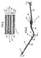
- the expandable arms 50 , 56are die cut in a serpentine pattern.
- the expandable arms 50 , 56comprise polypropylene or polyethylene fabric, Kapton, Mylar, or other flexible, memoryless material.
- the expandable arms 50 , 56expand, if necessary, by elongating the serpentine pattern. When expanded, a portion or all of the expandable arm is extended. Where only a portion of the expandable arm is extended, another portion remains folded.
- the expandable arms 50 , 56allow for extension as needed so that the chest assembly 12 can fit patients of various sizes and also allow for patient movement when the patient is wearing the chest assembly 12 .
- the extension arm 58allows for flexible positioning of the V electrode connector in the middle of the patient's chest such as placement at electrode position V 1 , V 2 or V 3 .
- the health care practitionermay desire not to utilize the extension arm 58 for taking electrocardiograph measurements.
- the extension arm 58is die cut with a perforated seam that connects the extension arm 58 and the linear run 54 along the length of the extension arm 58 . If the health care practitioner desires to use the extension arm 58 , the perforated seam is unbroken so that the extension arm 58 can be selectively positioned on the patient's chest.
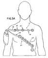
- the chest assembly 12may be configured such that the electrodes labeled RL, LA, and RA can positioned straight across the patient's chest. Such an embodiment is preferably used on an “out-patient” basis.
- the chest assembly 12 shown in FIG. 3Ahas a tail 46 that flows into an electrode retaining section 47 .
- the electrode retaining sectionmay be configured to attach to three electrodes, namely the RL, LA, and RA electrodes.
- the RL electrodeis positioned between the LA and RA electrodes.
- Expandable arms 56connect the LA and RA electrodes to the RL electrode and allow for extension as needed so that the chest assembly 12 can fit patients of various sizes and also allow for patient movement when the patient is wearing the chest assembly.
- the chest assembly 12can be used with a precordial assembly 60 to provide a “12-lead” analysis of the electrical activity of the heart.
- the precordial assembly 60is a one-piece flexible circuit that connects a plurality of electrode connectors 62 .
- the electrode connectors 62have releasable connections that connect to electrodes.
- the electrode connectors 62have snap terminals that connect to electrodes having snap terminals.
- Each electrode connector 62connects to an electrically conductive element or trace for transmitting electrical signals from a patient's heart.
- the electrically conductive elements or tracesrun along the precordial assembly 60 and connect to a precordial assembly connector 66 .
- the precordial assembly 60may be constructed similarly to the chest assembly 12 discussed above.
- the precordial assembly 60is capable of attaching to six electrodes selectively positioned on the abdomen and middle chest of the patient.
- the electrode connectors 62 of the precordial assembly 60are preferably labeled and color-coded so as to prevent a health care provider from applying or positioning the precordial assembly onto the patient improperly.
- the electrode connectors 62are preferably labeled V 1 , V 2 , V 3 , V 4 , V 5 , and V 6 , respectively.
- the precordial assembly 60is configured to provide flexible positioning of the precordial assembly 60 on the patient.
- FIG. 4is for illustrative purposes only, and thus, the precordial assembly 60 , as depicted in FIG. 4 , is not limited to any particular shape or configuration.
- the precordial assemblyhas a linear section or tail 68 extending from the precordial assembly connector 66 .
- the linear section or tail 68flows into an electrode retaining section 69 .
- the electrode retaining section 69has a first arcuate section 70 having a first transition section 72 .
- the V 2 electrode connector 62 battaches to the first transition section 72 .
- the V 1 electrode connector 62 aattaches to a first extension arm 74 connected to the first transition section 72 .
- a second arcuate section 76extends from the first transition section 72 .
- a second transition section 78abuts the second arcuate section 76 and the V 4 electrode connector 62 d attaches to the second transition section 76 .
- the V 3 electrode connector 62 cattaches to a second extension arm 80 connected the second transition section 78 .
- a third arcuate section 82flows from the second transition section 78 .
- the third arcuate section 82abuts a third transition section 84 .
- the V 5 electrode connector 62 eattaches to the third transition section 84 .
- a fourth arcuate section 86extends from the third transition section 84 .
- the V 6 electrode connector 62 fattaches to the fourth arcuate section 86 .
- the configuration of the precordial assembly 60allows the health care provider or physician to flexibly position the electrode connectors 62 as needed to properly situate the precordial assembly 60 on the patient and to allow for patient movement when the patient is wearing the precordial assembly 60 .
- the precordial assembly 60may be configured such that the electrodes labeled V 1 -V 6 can be diagonally positioned in a row across the patient's chest. Such an embodiment is preferably used on an “out-patient” basis.
- the precordial assembly 60 shown in FIG. 3Ahas tail 68 that flows into an electrode retaining section 69 .
- the electrode retaining sectionmay be configured such that the LL electrode is located at the end of the diagonal line formed by the V 1 -V 6 electrodes.
- the chest assembly 12 and the precordial assembly 60detect electrical signals generated by the heart during each beat and transfer these signals to the body electronics unit 14 .
- the body electronics unit 14acquires signals from the RL, RA, LL, LA, and V electrodes.
- the body electronics unit 14uses the RL electrode as a ground reference.
- the systemis operating in the “12 lead” mode (i.e.
- the body electronics unit 14acquires signals from the RL, RA, LL, and LA electrodes via the chest assembly 12 and acquires signals from the V 1 , V 2 , V 3 , V 4 , V 5 , and V 6 electrodes via the precordial assembly 60 .
- a various number of electrodesmay be monitored by the system.
- the health care provider or physicianmay choose to use only two electrodes to monitor the heart, seven electrodes to monitor the heart, or the like. In other words, the present system is not limited to performing a “7 lead” and “12 lead” analysis of the heart.
- the chest assembly 12 and the precordial assembly 60may be constructed to detect other vital signs of the patient, for example, pulse, respiration rate, heart rate, temperature, blood pressure, EEG signals, and pulse oximeter signals.
- the chest assembly 12connects to the body electronics unit 14 via a chest assembly connector 21 .
- the chest assembly connector 21inserts into a chest assembly port 88 located in the body electronics unit 14 .
- the precordial assembly 60(not shown) connects to the body electronics unit 14 via the precordial assembly connector 66 (not shown).
- the precordial assembly connector 66(not shown) inserts into a precordial assembly port 90 .
- Resistersare connected to the chest assembly port 88 and the precordial assembly port 90 to prevent excessive electrical current from entering the body electronics unit 14 —thereby ensuring that the body electronics unit 14 continues to operate properly in the presence a strong electrical current caused by a defibrillator (i.e.
- the chest assembly connector 21 and the precordial assembly connector 66are specifically keyed or configured to prevent the assembly connectors 21 , 66 from being inserted into the assembly ports 88 , 90 backwards, misaligned or otherwise improperly. Moreover, the chest assembly connector 21 is keyed or configured such that it is not compatible with the precordial assembly port 90 . Likewise, the precordial assembly connector 66 is keyed or configured such that it is not compatible with the chest assembly port 88 . Specifically, the chest assembly connector 21 has tongues specifically configured or arranged to fit into corresponding grooves of the chest assembly port 88 . Accordingly, the chest assembly connector 21 can only be connected to the chest assembly port 88 in one orientation.
- the chest assembly connector 21will not couple to the chest assembly port 88 .
- the precordial assembly connector 66has tongues specifically configured or arranged to fit into corresponding grooves of the precordial assembly port 90 .
- the chest assembly connector 21 and the precordial assembly connector 66(not shown) have retaining clips or flanges 92 located on the sides of the connectors 21 , 66 for removably securing the connectors 21 , 66 into the assembly ports 88 , 90 .
- other meansmay be used to removably secure the connectors 21 , 66 in the assembly ports 88 , 90 , such as screws, pins or the like.
- the assembly connectors 21 , 66may have spring flanges or clips 94 located at the tip of the connectors 21 , 66 for providing a bias or tension against the assembly ports 88 , 90 .
- the spring flanges or clips 94provide the connectors 21 , 66 with a secure fit within the assembly ports 88 , 90 , thereby reducing any play or movement of the connectors 21 , 66 within the assembly ports 88 , 90 .
- the electrically conductive elements or tracesare specifically configured on the connectors 21 , 66 so as to ensure that the electrical signals from the heart are properly transmitted to the body electronics unit 14 .
- the electrically conductive elements or tracesmust be sufficiently spaced apart or otherwise isolated in some manner to prevent arcing across the electrically conductive elements.
- the spacing of the electrically conductive elements or tracespermits the chest assembly and the precordial assembly to withstand defibrillation shock.
- the connectors 21 , 66have ribs 96 for preventing the electrically conductive elements or traces from coming into contact with metal objects or the like when the connectors 21 , 66 are not inserted into the assembly ports 88 , 90 .
- the chest assembly connector 21may have a sensor pin or ground pin 98 that completes a circuit within the body electronics unit 14 when the chest assembly connector 21 is plugged into the chest assembly port 88 , thereby activating the power and bringing the body electronic unit 14 out of “sleep mode.”
- the sensor pinhas specific tongue that corresponds and fits into a groove located in the chest assembly port 88 .
- the sensor pin 98serves as a means for the body electronics unit 14 to identify the chest assembly 12 and to prevent the use of other chest assemblies or electrocardiograph wearables that are not designed to be used with the on-body electronic unit 14 . In other words, the power of the body electronics unit 14 will not activate unless the body electronics unit 14 identifies or recognizes the sensor pin 98 of the chest assembly 12 .
- the precordial assembly connector 66may also have a sensor pin or ground pin 98 .
- the body electronics unit 14may have a power activation switch to turn the power “on” and “off” independent of any sensor pin configuration.
- the outside casing of the body electronics unit 14is constructed of lightweight, molded plastic, such as acrylonitrile-butadiene-styrene (ABS) or other suitable material.
- ABSacrylonitrile-butadiene-styrene
- the shape and configuration of the body electronics 14 unitis not limited to any particular shape or configuration.
- the body electronic unit 14removably secures to the patient's arm via an armband 100 , thus making the body electronics unit 14 readily accessibly to the patient.
- the armband 100is capable of attaching to either the patient's right or left arm and attaches via Velcro or other suitable fastening means such as pins, snaps, or the like.
- the body electronics unit 14slides under a strap or pocket on the armband 100 .
- the body electronics unit 14could be positioned in a pocket or pouch of patient gown, or a pendent or strap around a patient's neck.
- the body electronics unit 14could also be secured to the bed or other bedside mounting unit.
- the body electronic unit 14has a user interface 102 and a battery 104 .
- the user interface 102provides information to the patient pertaining to the system's operating status or functionality.
- an exemplary embodiment of the user interface 102may provide information on whether the body electronics unit 14 is communicating or transmitting normally to the base station 16 , whether the battery 104 of the body electronics unit 14 is charging or the battery 104 is low, whether the power of the body electronics unit 12 is activated, or whether the body electronics unit 14 or base station is malfunctioning.
- the user interface 102may provide instructions on the correct order or procedure for pairing or coupling the body electronics unit 14 with the base station 16 .
- Such informationmay be communicated to the patient via the user interface 102 in various ways, for example, LEDs, LCD, text, audible tones, etc.
- An exemplary embodiment of the user interfaceis shown in FIG. 7A . The user interface 102 is readily accessible to the patient when the body electronics unit 14 is secured to the armband 100 .
- the battery 104is inserted into a battery port 106 located in the bottom of the body electronics unit 14 .
- the battery 104is retained in the battery port 106 by latches or other suitable fastening means, such as clips, screws or the like.
- the battery 104is preferably a 3.6 V Li-ion rechargeable battery.
- the batteryis preferably constructed to have a charge indicator to indicate the amount of charge remaining in the battery. The battery 104 is readily accessible to the patient when the body electronics unit 14 is secured to the armband 100 .
- the body electronics unit 14controls the acquisition of the ECG signals from the chest assembly 12 and the precordial assembly 60 .
- a transmitter within the body electronics unit 14receives or acquires ECG signals from the chest assembly 12 and the precordial assembly 60 preferably at 3 kbps.
- the body electronics unit 14acquires signals from the RL, RA, LL, LA, and V electrodes.
- the systemis operating in the “12 lead mode” (i.e.
- the body electronics unit 14acquires signals from the RL, RA, LL, and LA electrodes via the chest assembly 12 and acquires signals from the V 1 thru V 6 electrodes via the precordial assembly 60 .
- other vital signs of the patientmay be detected by the system and transmitted to the body electronics unit 14 , for example pulse, respiration rate, heart rate, temperature, blood pressure, EEG signals and pulse oximeter signals.
- the detection of the respiration ratemay be achieved by obtaining a respiratory cycle or respirogram from an impedance pneumograph signal that is measured across two electrodes 20 , for example the RA and LL electrodes.
- the respiratory impedancemay be measured by applying a sinusoidal constant-current source between about 30 to 80 kHz across the electrodes 20 , preferably 39 kHz.
- the electrodes that collect respiration rate dataare also used to detect electrocardiograph signals.
- the current inventionis capable of simultaneously measuring a patient's respiration rate and cardiac activity.
- the body electronics unit 14may include a current source 107 A and a current source detection assembly that comprises a detection amplifier 107 B, and a demodulator 107 C to measure the respiratory impedance.
- the current source 107is capacitor-coupled to the RA and LL signals after the defibrillation resistors.
- the current source 107 Aoutputs a sinusoidal signal, for example, a 68- ⁇ A sinusoidal signal, which passes through the RA electrode, through the patient, and back through the LL electrode.
- a sinusoidal signalfor example, a 68- ⁇ A sinusoidal signal, which passes through the RA electrode, through the patient, and back through the LL electrode.
- the maximum load impedance for the current source 107 Ais 13.1 Kohm, which is based on a maximum output voltage of 2.5 Vpp or 0.89 Vrms.
- the maximum load impedanceis 4 Kohm, the maximum value for the defibrillation resisters is 4.54 Kohm.
- the detection amplifier 107 B and the demodulator 107 Cprocess the current source signal.
- the detection amplifier 107 Bprovides a high-impedance buffer and gain for the signal.
- the demodulator 107 Cconverts the amplitude-modulated signal to a low-frequency base impedance ( ⁇ 1000 ohm) and an AC-coupled and amplified respiration impedance signal ( ⁇ 1 ohm pp).
- the respiratory impedanceis split into a base impedance and a respiratory signal impedance to obtain more resolution for the respiratory signal impedance.
- the base impedance signalmay have a bandwidth of DC to 0.015 Hz while the respiration impedance signal has a bandwidth of 0.05 to 2.5 Hz. These signals may digitized at a sample rate of 10 Hz.
- the digitized impedance signalsare then transmitted to the base station 16 for reconstruction.
- the transmittermay comprise an application specific integrated circuit, a processor or other circuit, a plurality of signal channels 112 , a multiplexer 114 , an analog-to digital converter (ADC) 116 , a controller 118 , and a radio 120 . Additionally, fewer or different components can be used.
- the body electronics unit 14may have ten signal channels 112 corresponding to the eleven electrodes connected to the chest assembly 12 and the precordial assembly 60 .
- the electrode channels 112each comprise a connector 122 , a filter 124 , an amplifier 126 , a Nyquist filter 128 and a sample and hold circuit 130 .
- the connectors 122 of the signal channels 112connect to either the chest assembly port 88 or the precordial assembly port 90 , depending on whether the electrode channel 112 corresponds to an electrode located on the chest assembly 12 or the precordial assembly 60 .
- the filter 124comprises a low pass filter, such as for removing electromagnetic interference signals.
- the amplifier 126amplifies the signals from the electrodes.
- the Nyquist filter 128comprises a low pass filter for removing out-of-band high frequency content of the amplified signals to avoid sampling error.
- the sample and hold circuit 130enables the system to sample all nine electrode channels signals 112 at the same or relatively same time so that there is no differential error created when these signals are combined later in the ECG monitor.
- the multiplexer 114sequentially selects signals from the electrode signal channels 112 using time division multiplexing.
- the ADC 116converts the combined analog signals to digital signals for transmission.
- the controller 118comprises a digital signal processor (DSP) that decimates the digitized signals as to lessen the bandwidth required to transmit the signals.
- DSPalso performs two-sample averaging and a thirty-tap Finite Impulse Response (FIR) digital low pass filter.
- the radio 120modulates the digital signals with a carrier signal for transmission.
- the radio 120includes a demodulator for receiving information.
- the controller 118digitally transmits the ECG data to the base station 16 .
- the controller 118may transmit signals pertaining to physiological and non-physiological data such as token pairing information, pacemaker information, battery level information, electrode disconnection information, and other information as required.
- physiological and non-physiological datasuch as token pairing information, pacemaker information, battery level information, electrode disconnection information, and other information as required.
- vital signssuch as pulse, respiration rate, heart rate, temperature, blood pressure, EEG signals, and pulse oximeter signals may be transmitted.
- the body electronics unit 14continuously monitors the integrity of all patient electrode connections. This function may be achieved by supplying a direct current between all of the electrodes and the RL electrode and measuring the DC impedance between all of the electrodes and the RL electrode. When any electrode becomes disconnected, a lead wire becomes broken, or the impedance between any individual electrode and the RL electrode becomes very high, the voltage on that particular electrode goes out of range.
- the body electronics 14is capable of detecting the out of range voltage condition and sending a signal to the base station which in turn causes the base station to trigger the “lead off” alarm on the ECG monitor. Additionally, the body electronics unit 14 has a self-test function that monitors the integrity of the primary functions including the microprocessor, data acquisition, internal voltage references, and radio functionality. In the event a failure is detected, the body electronics unit will capture the fault condition, stop data acquisition and transmission and indicate that fault has occurred through the lead off alarm.
- the body electronics unit 14operates to minimize undesired noise or signals. For example, components are matched such that later application to a differential amplifier in a legacy ECG monitor for determining a heart vector is accurate. ECG vectors are not formed by the ECG system 10 , but rather by the legacy ECG monitor. Because the ECG system 10 is essentially “in-series” with the legacy ECG monitor, any error may produce undesirable results.
- One potential source of erroris differential error. This differential error can be observed on the legacy ECG monitor when the ECG monitor forms the ECG lead signals by combining the individual electrode signals in the ECG monitor input stage. This input stage comprises a difference, or differential, amplifier to eliminate common mode interference from the signals produced at the electrodes 20 .
- An artifactwill be present if there is any difference in how each of the electrode signals are processed when the legacy ECG's differential amplifier forms the ECG lead signals or ECG vectors. For example, if there is a difference in the gain of the amplifier, a difference in the phase shift associated with the anti-aliasing (Nyquist) filters, or a difference in how the respective sample and hold circuits treat the electrode signals, then this differential error creates an artifact on the legacy ECG monitor.
- One important technique to minimize this potential source of differential errorsis to choose a Nyquist filter cutoff frequency that is very high. This is because each individual filter will have differing group delay performance.
- the frequency that this group delay will affectis much higher than the frequency of the ECG signals, which are about 0.05 Hz to 150 Hz.
- the frequency of the ECG signalswhich are about 0.05 Hz to 150 Hz.
- any mismatch in the Nyquist filter componentswill not affect the accuracy of the individual electrode ECG signals. For example, picking a filter cutoff frequency of 1,200 Hz mitigates this source of error.
- the individual electrode ECG signalsare over sampled at about 3,000 Hz in order to not introduce aliasing.
- higher filter cutoff frequencies and correspondingly higher sampling ratesmay further reduce error.
- Lower cutoff frequencies and/or sampling ratemay be used.
- the electrode signalsare sampled at such a high rate, these signals may be decimated to minimize the required transmission bandwidth.
- the digital samplesare preferably decimated by a factor of eight in the controller of the body electronics unit 14 . Greater or lesser rates of decimation can be used, such as decimation as a function of the bandwidth available for transmission, the number of electrode signals to be represented, and the Nyquist sampling rate.
- the base station 16receives the transmitted signals sent from the body electronics unit 14 .
- the signalsare transmitted as radio or other signals modulated with a carrier signal.
- Various air-interfacescan be used for transmission, such as BLUETOOTH or IEEE 802.11b.
- the token key 132is inserted into the token key port 134 of the base station and reads and records an identification number for the base station 16 .
- the token key 132is then removed from the token key port 134 and inserted into the token key port 136 located in the body electronics unit 14 .
- the electronics unit 14receives the identification number for the base station 16 from the token key 132 .
- the token key 132reads and records the identification number for the body electronics unit 14 .
- the order in which the token key 132 is inserted into the body electronics unit 14 and the base station 16is not critical to the proper operation of the system.
- the user interface 102may provide the user or health care provider with instructions on the correct order for pairing the body electronics unit 14 with the base station 16 .
- the use of the token key 132allows the pairing function to occur while the body electronics unit 14 is worn by the patient. This feature eliminates the need to disconnect and reconnect the body electronics unit 14 when a patient needs to be connected to different ECG monitors as a result of being moved around a hospital. The patient's body electronics unit 14 is just repaired with a new base station using the token key 132 .
- the body electronics unit 14 and the base station 16After the body electronics unit 14 and the base station 16 are paired, the body electronics unit 14 and the base station 16 will remain communicating with each other as long as the token key 132 remains in the token key port 134 of the base station 16 (or the token key port 136 of the body electronics unit 14 , depending on the order of the pairing process). In other words, as soon as the token key 132 is removed from the base station 16 , the electronics unit 14 and the base station 16 will discontinue or cease communication. Any specific token key 132 can be used to pair any specific base station 16 with any specific body electronics unit 14 .
- the ECG systemcan be configured such that the body electronics unit 14 simultaneously communicates with more than one base station 16 .
- a body electronics unit 14can be configured to collect and transmit diagnostic “7-lead” ECG signals to a first base station 16 and collect and transmit diagnostic “12-lead” ECG signals to a second base station 16 .
- each body electronics unit 14may be configured with a temporary transmission mode that allows the body electronics unit 14 , which is already paired with and transmitting to a first base station 16 , to temporarily pair with and temporarily transmit ECG data to a second base station 16 .
- Such a configurationwill allow the health care provider to take a collect a temporary 12-lead ECG signal measurement from a patient who is already on continuous 7-lead ECG signal monitoring.
- the health care providerwill be required to attach the precordial assembly 60 (the chest assembly 12 will already be attached for 7-lead monitoring) to the body electronics unit 14 and the patient.
- a temporary 12-lead mode switch on the body electronics unit 14will be activated before the health care provider pairs the body electronics unit 14 with the second base station.
- the body electronics unit 14 and the second base station 16will be paired in accordance with the pairing method discussed above.
- the body electronics unit 14will begin to transmit 12-lead ECG data with the second base station 16 while simultaneously transmitting 7-lead ECG data to the first base station 16 .
- the body electronics unit 14can be configured to simultaneously transmit in the temporary mode for a sufficient, predetermined period of time to collect the 12-lead diagnostic ECG reading.
- the body electronics unit 14will be configured to transmit in the temporary mode for at least two minutes. After the predetermined time period for temporary transmission has ended, the body electronics unit 14 will stop transmitting to the second base station 16 .
- the outside casing of the base station 16is constructed of lightweight, molded plastic, such as acrylonitrile-butadiene-styrene (ABS) or other suitable material.
- ABSacrylonitrile-butadiene-styrene
- the shape and configuration of the base station 16is not limited to any particular shape or configuration.
- the base station 16is a portable transceiver that can be placed in any location and does not necessarily have to be placed or secured in any fixed location.
- the base station 16is preferably removably secured to an ECG monitor 138 via suitable mounting means, such as Velcro®, dual-lock strips, double-sided foam tape, or the like.
- the base station 16is removably mounted to a mounting plate secured near the ECG monitor 138 via suitable mounting means.
- the base station 16can be incorporated into the monitor 138 .
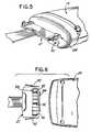
- the base station 16has a cradle 140 for storing the body electronics unit 14 when the body electronics unit 14 is not in use or otherwise off the patient.
- the base station 16has a battery port 142 in which a base station battery 144 is removably inserted.
- the base station 16may be constructed to have a plurality of battery ports that store and charge batteries when the batteries are not being used. When the base station 16 is not plugged into an AC wall power inlet, the base station battery 144 provides power to the base station 16 .
- the base station 16When the base station 16 is operating on AC wall power, the base station 16 charges the base station battery 144 when the base station battery 144 is in the battery port 142 .
- the base station 16has a power switch that activates/deactivates the power to the base station 16 and a power cord connection 148 for connecting a power cord to an AC wall power inlet.
- the base station battery 144is preferably a 3.6 V Li-ion rechargeable battery. Accordingly, the base station battery 144 and the body electronics unit battery 104 are preferably identical and interchangeable, such that each battery can be used in either the body electronics unit 14 or the base station 16 .
- the systemis designed such that a discharged body electronics unit battery 104 is swapped for a charged base station battery 144 . In this manner a charged battery is always readily available for the body electronics unit.
- the base station 16has a lead switch that allows the health care provider to instruct the base station 16 to operate in “7 lead” mode or “12 lead” mode.
- the base station 16has a user interface 152 that provides information to the health provider or patient pertaining to the system's operating status or functionality.
- the user interface 152may provide information on whether the body electronics unit 14 is communicating or transmitting normally to the base station 16 , whether the base station battery 144 is charging or the battery 144 is low, whether the body electronics unit battery 104 is low, or whether the power of the base station 16 is activated, whether the base station 16 is malfunctioning or otherwise requires servicing.
- the user interface 102may provide instructions on the correct order or procedure for pairing or coupling the body electronics unit 14 with the base station 16 .
- Such informationmay be communicated to the health care provider or patient via the user interface 152 in various ways, for example, LED's, LCD, text, audible tones, etc.
- An exemplary embodiment of the user interface 102is shown in FIG. 11A .
- the base stationhas a self-test function that monitors the integrity of the primary functions including the microprocessor, data acquisition, internal voltage references, and radio functionality. In the event a failure is detected, the body electronics unit will capture the fault condition, stop data acquisition and transmission and indicate that fault has occurred through the lead off alarm.
- a receiver located within the base station 16receives signals sent to the base station 16 from the body electronics unit 14 .
- the receiverincludes a radio 156 , a controller 158 , a digital-to-analog converter (DAC) 160 , a de-multiplexer 162 , and a plurality of electrode signal channels 166 . Additionally, fewer or different components can be used.
- the radio 156demodulates the received signals for identifying digital data representing the combined electrode signals.
- the radio 156includes a modulator for transmitting control information.
- the controller 158controls operation of the various components and may further process the signals from the radio 156 , such as interpolating data, converting the signals to digital information, generating control signals for the transmitter in the electronics unit 14 , operating any user output or input devices, and diagnosing operation of the ECG system.
- the controller 118interpolates the electrode signals to return the effective sample rate to about 3 kHz or another frequency. This enables the reconstruction filters to have a cutoff frequency many times the bandwidth of the electrode signals, thus minimizing any differences in group delay at the frequencies of interest, i.e. less than 150 Hz.
- the DAC 160converts the digital signals to analog signals.
- the demultiplexer 162separates the individual regenerated electrode signals onto the separate electrode signal channels 166 .
- the receivermay have a transceiver that operates pursuant to the BLUETOOTH air interface specification for two-way communication with the transmitter in the body electronics unit 14 .
- the receivermay have nine electrode signal channels 166 corresponding to the ten electrodes.
- the V electrode signalis output to the “V/V 1 ” terminal on the receiver.
- the V electrode signalis discarded and the V 1 electrode signal is output to the “V/V 1 ” terminal on the receiver.
- the electrode signal channels 166each comprise a sample and hold circuit 168 , a filter 170 , and an attenuator 172 .
- the sample and hold circuit 168is controlled by the controller 118 so that the converted electrode signals appear simultaneously on each electrode signal channel 166 .
- Other embodimentsmay include individual DAC's that provide the signal substantially simultaneously.
- the filter 170comprises a low pass reconstruction filter for removing high frequency signals associated with the DAC conversion process.
- the attenuator 172comprises an amplifier for decreasing the amplitude to a level associated with signals at the electrodes, which were earlier amplified in the amplifiers of the body electronics unit 14 . This results in a unity system gain so as not to introduce error between the electrodes and the conventional ECG monitor.
- the base station 16may include a respiration network 173 inserted in series with the electrode signal channel 166 , that corresponds to the RA electrode, to reconstruct the digitized impedance signals sent from the electronics body unit 14 .
- the respiration network 173may include digitally controlled resistors 173 A and dual digital potentiometers 173 B, one used for the base impedance signal and one for the respiratory signal, in series with the digitally controlled resistors.
- the base station 16may further include a log taper potentiometer (not shown) to reduce the linearity caused by using the digitally controlled resistors with the dual digital potentiometers.
- the base station 16transmits the ECG signals and other physiological and non-physiological data to the ECG monitor 138 via pre-existing or conventional monitor cables 174 .
- the informationis displayed on the ECG monitor and reviewed by a physician.
- the monitor cablesremovably insert onto snap terminals 176 located on the base station 16 .
- the base station 16has ten snap terminals 176 arranged on the left and right side of the base station 16 .
- the snap terminals 176 and the monitor cablesare preferably labeled and color-coded so that the monitor cables are properly connected to the base station 16 .
- the five snap terminals 176 located on the left side of the base station 16 and the monitor cablemay be labeled as RL, LA, LL, RA, and V/V 1 .
- the five snap terminals 176 on the right side of the base station 16 and the monitor cablemay be labeled V 2 , V 3 , V 4 , V 5 , and V 6 .
- both the chest assembly 12 and the precordial assembly 60is used) both the monitor cables are plugged into the snap terminals 176 —the top four snap terminals 176 on the left side of the base station 16 will be used for chest assembly electrodes and the remaining six snap terminals 176 will be used for precordial assembly electrodes.
- the ECG system of the present inventionmay be configured to monitor and transmit pacemaker pulse information from the body electronics unit 14 to the base station 16 .
- the body electronics unit 14may have a plurality of signal channels 112 that are sampled to collect physiological data from the patient. Preferably, there are ten channels. Three of the channels correspond to the LA, RA, and LL electrodes and are sampled at 16 kHz. The seven remaining channels correspond to the V and V 1 -V 6 electrodes and are sampled at 4 kHz. The channels corresponding to the LA, RA, and LL electrodes are sampled at a faster rate in order to detect fast transients (i.e., pacemaker pulses) in the data from these channels.
- fast transientsi.e., pacemaker pulses
- Sampling of the plurality of signal channels 112may be performed by a serial ADC.
- the ADCcan be 16-bit converter.
- a bank or series of multiplexersselect the channels for sampling.
- the virtual channelsallow the system to perform nineteen samplings at 4 kHz, rather than three samplings at 16 kHz and seven sampling at 4 kHz.
- These virtual channelsare four copies of each of the three channels corresponding to the LA, RA and LL electrodes and one copy of all the remaining channels corresponding to the V and V 1 -V 6 electrodes.
- the virtual channelsare LA i , LA ii , LA iii , LA iv , RA i , RA ii , RA iv , LL i , LL ii , LL iii , LL iv , V, and V 1 -V 6 .
- the order of and timing of the sampling of the signal channelsis depicted in FIG. 18 .
- a first data set 200is formed.
- the first data set 200is referred to as the raw data set.
- the data from the channels corresponding to the LA, RA, LL electrodesis copied and reorganized into a second data set 202 .
- the second data 202 setis referred to as the snapshot data set.
- the differences between samples n and n ⁇ 2is calculated for each lead. If the differences between samples n and n ⁇ 2 exceed a predetermined threshold value, the previous, current, and next snapshot data set are packaged and transmitted to the base station 16 .
- the three snapshot data setstotal 6 ms of high-resolution data.
- the raw dataBefore the raw data set can be transmitted to the base station 16 , the raw data is averaged and filtered. Averaging and filtering reduces the gaussian-distributed noise inherent in the A/D conversion. In addition, averaging the raw data set provides a uniform sampling rate for all channels before the data enters a series of Finite Impulse Response (FIR) filters.
- FIRFinite Impulse Response
- the raw data set that enters the averaging and filtering processrepresent 2 ms worth of data packets for all of the channels.
- the data packetscontain thirty-two samples of the channels corresponding to the LA, RA, LL electrodes and eight samples of the channels corresponding to the V and V 1 -V 6 electrodes.
- the averaging processconverts the data packets into four samples of the ten channels for an effective data rate of 2 kHz.
- a unity-gain, 150-Hz low-pass filteris applied to the data set.
- the low-pass-filtered data setthen runs through two stages of FIR half band filtering and decimation.
- the 2 kHz of datais converted to 500 Hz.
- Four samples of each channelare decimated to two samples (2 kHz to 1 kHz) and then decimated from two samples to one sample (1 kHz to 500 Hz).
- the 500 Hz datahas a maximum unaliased frequency of 250 Hz and has been low passed filtered by 150 Hz to eliminate any possibility of aliasing.
- FIG. 21depicts the filtering process.
- the raw data setAfter decimation, the raw data set is ready for packaging and transmission via the BLUETOOTH air interface. Each data point represents 2 ms of data (500 Hz sampling). The maximum frequency that this data can represent is 250 Hz and the data has been filtered to reject frequencies above 150 Hz.
- the raw data set and the snapshot data setare packaged for transmission to the base station 16 via BLUETOOTH air interface transmission as depicted in FIG. 22 .
- the raw data set and the snapshot data setare packaged into raw data set packets and snapshot data set packets. Each data packet has a packet ID so that the raw data set and the snapshot data set can be properly paired at the base station 16
- the raw data packet transmitted from the body electronics unit 14is interpolated and duplicated at the base station 16 .
- Two FIR interpolated filtersconvert one sample of raw data into four samples.
- FIG. 23depicts the FIR interpolation process.
- the data for each of the channels corresponding to the LA, RA, LL electrodesare duplicated eight times to create thirty-two samples (2 ms of data at 16 kHz playback rate).
- Data for each of the channels corresponding to the V and V 1 -V 6 electrodesare duplicated two times to create eight samples (2 ms of data at 4 kHz playback rate).
- the base station 16receives one channel of data that represents either the data from the V electrode or data from the V 1 electrode.
- the base station 16has a single port allocated to this data, regardless of whether the data is from the V electrode or the V 1 electrode. To preserve the same sequence and timing on D/A playback, two virtual channels are created from the single channel corresponding to the V/V 1 electrodes. The data for the V/V 1 channel is copied to create a V channel and V 1 channel.
- FIG. 24depicts the duplication of the interpolated data.
- the snapshot data setcan be placed into the interpolated raw data to form a reconstructed, high-resolution waveform.
- the ID of that raw data packetis compared with the next available snapshot data packet. If the ID from the raw data packet matches the ID from the snapshot data packet, the raw data corresponding to the LA, RA, LL electrodes is overwritten with the data contained within the snapshot data set. If the ID from the raw data packet matches the ID from the snapshot data packet does not match, the snapshot data packet is considered out of sync and rejected or erased.
- FIG. 25depicts the restoration of the pacemaker pulse.
- FIG. 26depicts the sequence and timing in which the nineteen virtual channels are played out.
- an adapter assembly 178may be used to connect the chest assembly 12 or the precordial assembly 60 to the ECG monitor 138 .
- the adaptor assembly 178allows the chest assembly 12 or precordial assembly 60 to be plugged directly into a conventional or existing telemetry transmitter.
- FIG. 14depicts the adapter assembly 178 having an assembly receptacle 180 that connects to the chest assembly 12 (not shown) or the precordial assembly 60 (not shown) and a telemetry box receptacle 182 that connects to a conventional or existing telemetry transmitter.
- the adaptor assembly 178allows the chest assembly 12 or precordial assembly 60 to be plugged directly into a conventional or existing ECG monitor trunk cables.
- FIG. 15depicts the adaptor assembly 178 having an assembly receptacle 184 for connecting to the chest assembly 12 (not shown) or the precordial assembly 60 (not shown) and a cable assembly 185 for connecting to a conventional or existing ECG monitor trunk cable.
- the cable assembly 185has a cable 186 that connects to a trunk cable adaptor 188 for connecting to an ECG monitor trunk cable.
- the adaptor assembly 178allows the chest assembly 12 or precordial assembly 60 to be plugged directly into standard lead wires that connect to an ECG monitor.
- Various configurations of the adapter 178are possible depending on the connector configuration of the standard lead wires.
- FIG. 17depicts the method of monitoring the cardiac activity in the patient's heart using the wireless ECG system of the present invention.
- electrodesare placed on the patient's body.
- the chest assembly 12 and/or precordial assembly 60are positioned on the patient's body by connecting the electrode connectors 21 , 62 to the electrodes.
- the chest assembly 12 and/or the precordial assembly 60are plugged into the body electronics unit 14 .
- step 204the electronics unit 14 and the base station 16 are paired or coupled by inserting the token key 132 into the base station 16 , removing the token key 132 from the base station 16 , inserting the inserting the token key 132 into the body electronics unit 14 , removing the token key 132 from the electronics unit 14 , and reinserting the token key 132 into the base station 16 .
- couplingcan be accomplished by inserting the token key 132 into the body electronics unit 14 , removing the token key 132 from the body electronics unit, inserting the token key 132 into the base station 16 , removing the token key 132 from the base station 16 and reinserting the token key 132 into the body electronics unit 14 .
- step 206electrical signals from the patient's heart are detected and transmitted to the body electronics unit 14 via chest assembly 12 and the precordial assembly 60 .
- step 208the electrical signals from the heart are transformed by the body electronics unit 14 from analog signals to digital signals.
- the body electronics unit 14transmits the digital signals to the base station 16 via radio transmission.
- step 212the base station 16 transforms the digital signals into analog signals.
- step 214the base station 16 transmits the analog signals to the ECG monitor 138 via monitor cables 174 .
- step 216the ECG monitor 138 processes the analog signals into meaningful information that can be displayed on the monitor 138 .
- various air-interfacescan be used for transmitting the physiological and non-physiological data from the body electronics unit 14 to the base station 16 .
- the technology used for the signal transmission between the body electronics unit 14 and the base station 16is based on the BLUETOOTH air interface specification for two-way communication.
- the BLUETOOTH air interface radio systemdepicted in FIG. 27 , consists of a radio unit 300 , a link control unit 302 , and a support unit 304 for link management and host terminal interface functions.
- BLUETOOTH air interface systemmay provide a point-to-point connection (only one body electronics unit 14 and one base station 16 involved), or a point-to-multipoint connection (when multiple body electronics units 14 and base stations 16 are involved).
- the transmission channelis shared among several electronics units 14 and base stations 16 .
- a “piconet”is formed.
- the base station 16performs as the master of the piconet
- the electronics unit 14performs as the slave.
- Each piconetcan only have a single master. However, slaves can participate in different piconets on a time-division multiplex basis. In addition, a master in one piconet can be a slave in another piconet. The piconets shall not be time or frequency synchronized. Each piconet has its own hopping channel.
- the radio 300uses a spread spectrum, frequency hopping, full-duplex signal at up to 1600 hops/sec.
- the signalhops among the radio frequency channels at 1 MHz intervals to provide a high degree of interference immunity.
- Informationis exchanged through packets. Each packet is transmitted on a different hop frequency.
- a packetnominally covers a single slot (e.g., 1 MHz bandwidth), but can be extended to cover up to five slots.
- the BLUETOOTH air interface specificationcan support an asynchronous data channel (e.g., one direction), up to three simultaneous synchronous voice channels, or a channel, which simultaneously supports asynchronous data and synchronous voice.
- the asynchronous channelcan support maximal 723.2 kb/s asymmetric (and still up to 57.6 kb/s in the return direction), or 433.9 kb/s symmetric.
- the channelis represented by a pseudo-random hopping sequence hopping through the radio frequency channels.
- the hopping sequenceis unique for the piconet and is determined by the Bluetooth device address of the master (e.g., each base station 16 has a transceiver that is allocated a unique 48-bit BLUETOOTH air interface device address).
- the phase in the hopping sequenceis determined by the BLUETOOTH air interface clock of the master.
- the channelis divided into time slots where each slot corresponds to an RF hop frequency. Consecutive hops correspond to different RF hop frequencies.
- the nominal hop rateis 1600 hops/s. All BLUETOOTH air interface units participating in the piconet are time and hop synchronized to the channel.
- Each time slotis 625 ⁇ s in length.
- the masteri.e., the base station 16
- slavei.e., the body electronics unit 14
- a time division duplexing (TDD) schemeis used where a master and a slave alternatively transmit in a synchronous manner.
- the mastershall start its transmission in even numbered time slots only, and the slave shall start its transmission in odd numbered time slots only.
- the packet startshall be aligned with the slot start.
- Packets transmitted by the master or the slavemay extend over or up to five time slots. Due to packet types that cover more than a single slot, master transmission may continue in odd numbered slots and slave transmission may continue in even numbered slots.
- the RF hop frequencyshall remain fixed for the duration of the packet.
- the RF hop frequency to be usedis derived from the current BLUETOOTH air interface clock value.
- the RF hop frequency to be used for the entire packetis derived from the Bluetooth clock value in the first slot of the packet.
- the RF hop frequency in the first slot after a multi-slot packetshall use the frequency as determined by the current BLUETOOTH air interface clock value. If a packet occupies more than one time slot, the hop frequency applied shall be the hop frequency as applied in the time slot where the packet transmission was started.
- the hoping sequence selection procedureconsists of selecting a sequence and mapping this sequence on the hop frequencies.
- the type of sequence selectedmostly depends on the state of the devices communicating.
- Every BLUETOOTH air interface unithas an internal system clock, which determines the timing and hopping of the transceiver.
- the BLUETOOTH air interface clockis derived from a free running native clock, which is never adjusted and is never turned off. For synchronization with other units, only offsets are used that, added to the native clock, provide temporary BLUETOOTH air interface clocks which are mutually synchronized. It should be noted that the BLUETOOTH air interface clock has no relation to the time of day; it can therefore be initialized at any value.
- the BLUETOOTH air interface clockprovides the heart beat of the Bluetooth transceiver. Its resolution is at least half the transmission or reception slot length, or 312.5 .mu.s. The clock has a cycle of about a day.
- the timing and the frequency hopping on the channel of a piconetare determined by the BLUETOOTH air interface clock of the master.
- the master clockis communicated to the slaves.
- Each slaveadds an offset to its native clock to be synchronized to the master clock. Since the clocks are free running, the offsets have to be updated regularly. This offset is updated each time a packet is received from the master: by comparing the exact receiver timing of the received packet with the estimated receiver timing, the slaves correct the offset for any timing misalignments.
- Frequency hoppingis accomplished with the use of a fast settling phase locked loop (PLL). Since the BLUETOOTH air interface hops up to 1600 hops/second, the PLL remains on a channel only 625 us, which means that the PLL lock time can be only a fraction of this, or else the system will be waiting too long for the PLL to switch frequencies and the data rate will be too slow. Therefore, typically, after a 220 .mu.s settling delay, the voltage control oscillator (VCO) of the PLL is locked and is at the prescribed RF hop channel. The RF output of the VCO is used as a local oscillator.
- VCOvoltage control oscillator
- the data transmittedhas a symbol rate of 1 Ms/s (mega sample per second).
- a Gaussian-shaped, binary frequency shift keying (FSK) modulationis applied with a bandwidth bit-duration (BT) product of 0.5.
- a binary oneis represented by a positive frequency deviation, and a binary zero is represented by a negative frequency deviation.
- the maximum frequency deviationshall be between 140 kHz and 175 kHz.
- the modulation indexmust be between 0.28 and 0.35.
- the bit ordering when defining packets and messagesfollows the Little Endian format (i.e., the least significant bit (LSB) is the first bit sent over the air and in illustrations, the LSB is shown on the left side). Furthermore, data fields generated internally, such as the packet header fields and payload header length, are transmitted with the LSB first.
- the data on the piconet channelis conveyed in packets.
- Each packetconsists of 3 entities: the access code, the header, and the payload.
- the access code and headerare of fixed size: 72 bits and 54 bits respectively.
- the payloadcan range from zero to a maximum of 2745 bits.
- Each packetstarts with an access code. If a packet header follows, the access code is 72 bits long; otherwise the access code is 68 bits long.
- This access codeis used for synchronization, DC offset compensation, and identification.
- the access codeidentifies all packets exchanged on the channel of the piconet: all packets sent in the same piconet are preceded by the same channel access code.
- a sliding correlatorcorrelates against the access code and triggers when a threshold is exceeded. This trigger signal is used to determine the receive timing.
- both the header and the payloadare scrambled with a data whitening word in order to randomize the data from highly redundant patterns and to minimize DC bias in the packet.
- the scramblingis performed prior to field error control (FEC) encoding.
- FECfield error control
- the received datais descrambled using the same whitening word generated in the recipient.
- the descramblingis performed after FEC decoding.
- a return packetis expected N ⁇ 625 ⁇ s after the start of the transmitter burst where N is an odd, positive integer. N depends on the type of the transmitted packet. To allow for some time slipping, an uncertainty window is defined around the exact receive timing. During normal operation, the window length is 20 ⁇ s, which allows the receiver burst to arrive up to 10 ⁇ s too early or 10 ⁇ s too late.
Landscapes
- Health & Medical Sciences (AREA)
- Life Sciences & Earth Sciences (AREA)
- Engineering & Computer Science (AREA)
- Molecular Biology (AREA)
- Animal Behavior & Ethology (AREA)
- Pathology (AREA)
- Physics & Mathematics (AREA)
- Biomedical Technology (AREA)
- Heart & Thoracic Surgery (AREA)
- Medical Informatics (AREA)
- Veterinary Medicine (AREA)
- Surgery (AREA)
- Biophysics (AREA)
- General Health & Medical Sciences (AREA)
- Public Health (AREA)
- Cardiology (AREA)
- Physiology (AREA)
- Computer Networks & Wireless Communication (AREA)
- Chemical & Material Sciences (AREA)
- Dispersion Chemistry (AREA)
- Measurement And Recording Of Electrical Phenomena And Electrical Characteristics Of The Living Body (AREA)
Abstract
Description
Claims (18)
Priority Applications (14)
| Application Number | Priority Date | Filing Date | Title |
|---|---|---|---|
| US10/349,486US20040127802A1 (en) | 2001-07-17 | 2003-01-22 | Wireless ECG system |
| US10/439,356US7933642B2 (en) | 2001-07-17 | 2003-05-16 | Wireless ECG system |
| DE60331833TDE60331833D1 (en) | 2002-07-01 | 2003-07-01 | WIRELESS ECG DEVICE |
| AT03742358TATE461656T1 (en) | 2002-07-01 | 2003-07-01 | WIRELESS ECG DEVICE |
| MXPA04012556AMXPA04012556A (en) | 2002-07-01 | 2003-07-01 | WIRELESS ELECTROCARDIOGRAPHIC SYSTEM. |
| EP03742358AEP1519677B9 (en) | 2002-07-01 | 2003-07-01 | Wireless ecg system |
| AU2003280415AAU2003280415A1 (en) | 2002-07-01 | 2003-07-01 | Wireless ecg system |
| PCT/US2003/020680WO2004002301A2 (en) | 2001-07-17 | 2003-07-01 | Wireless ecg system |
| JP2004518163AJP2005532849A (en) | 2002-07-01 | 2003-07-01 | Wireless ECG system |
| US11/105,231US20050251003A1 (en) | 2001-07-17 | 2005-04-13 | Disposable chest assembly |
| US11/105,230US20050251002A1 (en) | 2001-07-17 | 2005-04-13 | Vital signs monitoring assembly having elastomeric connectors |
| US11/105,232US7860557B2 (en) | 2001-07-17 | 2005-04-13 | Radiolucent chest assembly |
| US12/955,490US20110092835A1 (en) | 2001-07-17 | 2010-11-29 | Wireless ecg system |
| US13/020,284US8255041B2 (en) | 2001-07-17 | 2011-02-03 | Wireless ECG system |
Applications Claiming Priority (4)
| Application Number | Priority Date | Filing Date | Title |
|---|---|---|---|
| US09/908,509US6611705B2 (en) | 2000-07-18 | 2001-07-17 | Wireless electrocardiograph system and method |
| US09/998,733US7197357B2 (en) | 2001-07-17 | 2001-11-30 | Wireless ECG system |
| US39288202P | 2002-07-01 | 2002-07-01 | |
| US10/439,356US7933642B2 (en) | 2001-07-17 | 2003-05-16 | Wireless ECG system |
Related Parent Applications (1)
| Application Number | Title | Priority Date | Filing Date |
|---|---|---|---|
| US09/998,733Continuation-In-PartUS7197357B2 (en) | 2001-07-17 | 2001-11-30 | Wireless ECG system |
Related Child Applications (5)
| Application Number | Title | Priority Date | Filing Date |
|---|---|---|---|
| US11/105,231ContinuationUS20050251003A1 (en) | 2001-07-17 | 2005-04-13 | Disposable chest assembly |
| US11/105,232ContinuationUS7860557B2 (en) | 2001-07-17 | 2005-04-13 | Radiolucent chest assembly |
| US11/105,230ContinuationUS20050251002A1 (en) | 2001-07-17 | 2005-04-13 | Vital signs monitoring assembly having elastomeric connectors |
| US12/955,490ContinuationUS20110092835A1 (en) | 2001-07-17 | 2010-11-29 | Wireless ecg system |
| US13/020,284ContinuationUS8255041B2 (en) | 2001-07-17 | 2011-02-03 | Wireless ECG system |
Publications (2)
| Publication Number | Publication Date |
|---|---|
| US20040073127A1 US20040073127A1 (en) | 2004-04-15 |
| US7933642B2true US7933642B2 (en) | 2011-04-26 |
Family
ID=36337622
Family Applications (6)
| Application Number | Title | Priority Date | Filing Date |
|---|---|---|---|
| US10/439,356Expired - Fee RelatedUS7933642B2 (en) | 2001-07-17 | 2003-05-16 | Wireless ECG system |
| US11/105,230AbandonedUS20050251002A1 (en) | 2001-07-17 | 2005-04-13 | Vital signs monitoring assembly having elastomeric connectors |
| US11/105,232Expired - LifetimeUS7860557B2 (en) | 2001-07-17 | 2005-04-13 | Radiolucent chest assembly |
| US11/105,231AbandonedUS20050251003A1 (en) | 2001-07-17 | 2005-04-13 | Disposable chest assembly |
| US12/955,490AbandonedUS20110092835A1 (en) | 2001-07-17 | 2010-11-29 | Wireless ecg system |
| US13/020,284Expired - Fee RelatedUS8255041B2 (en) | 2001-07-17 | 2011-02-03 | Wireless ECG system |
Family Applications After (5)
| Application Number | Title | Priority Date | Filing Date |
|---|---|---|---|
| US11/105,230AbandonedUS20050251002A1 (en) | 2001-07-17 | 2005-04-13 | Vital signs monitoring assembly having elastomeric connectors |
| US11/105,232Expired - LifetimeUS7860557B2 (en) | 2001-07-17 | 2005-04-13 | Radiolucent chest assembly |
| US11/105,231AbandonedUS20050251003A1 (en) | 2001-07-17 | 2005-04-13 | Disposable chest assembly |
| US12/955,490AbandonedUS20110092835A1 (en) | 2001-07-17 | 2010-11-29 | Wireless ecg system |
| US13/020,284Expired - Fee RelatedUS8255041B2 (en) | 2001-07-17 | 2011-02-03 | Wireless ECG system |
Country Status (1)
| Country | Link |
|---|---|
| US (6) | US7933642B2 (en) |
Cited By (32)
| Publication number | Priority date | Publication date | Assignee | Title |
|---|---|---|---|---|
| US20070153705A1 (en)* | 2005-12-29 | 2007-07-05 | Rosar George C | System and method for synchronous wireless communication with a medical device |
| US20070180140A1 (en)* | 2005-12-03 | 2007-08-02 | Welch James P | Physiological alarm notification system |
| US20100276195A1 (en)* | 2009-04-29 | 2010-11-04 | Mindray Ds Usa, Inc. | Cables for patient monitoring and related systems and methods |
| US20110054286A1 (en)* | 2009-08-27 | 2011-03-03 | William Crosby | Expandable Electrode Pad |
| US20110152628A1 (en)* | 2009-12-22 | 2011-06-23 | Mindray Ds Usa, Inc. | Cables for patient monitoring and related systems with integrated front end |
| US20120190994A1 (en)* | 2011-01-26 | 2012-07-26 | Samsung Electronics Co., Ltd. | Apparatus and method for measuring biological signal with multiple unit measurers |
| US20120306662A1 (en)* | 2011-06-06 | 2012-12-06 | Halthion Medical Technologies, Inc. | Data collection module for a physiological data collection system |
| US8433399B1 (en) | 2012-01-03 | 2013-04-30 | Farhad David Nosrati | Method and apparatus for an interactively programmable ECG device with wireless communication interface to remote computing devices |
| US8514067B2 (en) | 2011-08-16 | 2013-08-20 | Elwha Llc | Systematic distillation of status data relating to regimen compliance |
| US20140275876A1 (en)* | 2013-03-15 | 2014-09-18 | Covidien Lp | Systems and methods for locating and/or identifying a wireless sensor associated with a patient monitor |
| US9142117B2 (en) | 2007-10-12 | 2015-09-22 | Masimo Corporation | Systems and methods for storing, analyzing, retrieving and displaying streaming medical data |
| US9218454B2 (en) | 2009-03-04 | 2015-12-22 | Masimo Corporation | Medical monitoring system |
| US9226680B1 (en) | 2013-02-12 | 2016-01-05 | David Kendricks | Patient electrode connectors for electrocardiograph monitoring system |
| US9307914B2 (en) | 2011-04-15 | 2016-04-12 | Infobionic, Inc | Remote data monitoring and collection system with multi-tiered analysis |
| US9323894B2 (en) | 2011-08-19 | 2016-04-26 | Masimo Corporation | Health care sanitation monitoring system |
| USD794807S1 (en) | 2016-04-29 | 2017-08-15 | Infobionic, Inc. | Health monitoring device with a display |
| USD794805S1 (en) | 2016-04-29 | 2017-08-15 | Infobionic, Inc. | Health monitoring device with a button |
| USD794806S1 (en) | 2016-04-29 | 2017-08-15 | Infobionic, Inc. | Health monitoring device |
| US20170273591A1 (en)* | 2014-08-22 | 2017-09-28 | Children's Medical Center Corporation | Multielectrode ecg sensor |
| US9882428B2 (en) | 2012-02-17 | 2018-01-30 | University Of Virginia Patent Foundation | Energy harvesting and control for sensor node |
| US9968274B2 (en) | 2016-04-29 | 2018-05-15 | Infobionic, Inc. | Systems and methods for processing ECG data |
| US9986929B1 (en) | 2017-03-01 | 2018-06-05 | CB Innovations, LLC | Emergency cardiac and electrocardiogram electrode placement system |
| US10007758B2 (en) | 2009-03-04 | 2018-06-26 | Masimo Corporation | Medical monitoring system |
| US10032002B2 (en) | 2009-03-04 | 2018-07-24 | Masimo Corporation | Medical monitoring system |
| SE1850808A1 (en)* | 2018-06-29 | 2019-12-30 | Coala Life Ab | Electrode extension assembly for a portable ecg and pcg sensor unit |
| USD872279S1 (en) | 2017-12-22 | 2020-01-07 | CB Innovations, LLC | Emergency cardiac and electrocardiogram electrode placement system |
| USD877912S1 (en) | 2017-12-22 | 2020-03-10 | CB Innovations, LLC | Cable controller for an electrocardiogram electrode placement system |
| US10660520B2 (en) | 2009-03-27 | 2020-05-26 | Braemar Manufacturing, Llc | Ambulatory and centralized processing of a physiological signal |
| US10893818B2 (en) | 2017-03-01 | 2021-01-19 | CB Innovations, LLC | Emergency cardiac and electrocardiogram electrode placement system |
| US11864858B1 (en) | 2017-03-01 | 2024-01-09 | CB Innovations, LLC | Emergency cardiac and electrocardiogram electrode system with wireless electrodes |
| US11896393B1 (en) | 2017-03-01 | 2024-02-13 | CB Innovations, LLC | Wearable diagnostic electrocardiogram garment |
| US12251227B1 (en) | 2017-03-01 | 2025-03-18 | CB Innovations, LLC | Emergency cardiac and electrocardiogram electrode placement system with artificial intelligence |
Families Citing this family (197)
| Publication number | Priority date | Publication date | Assignee | Title |
|---|---|---|---|---|
| EP1290652A2 (en) | 2000-05-05 | 2003-03-12 | Hill-Rom Services, Inc. | Hospital monitoring and control system and method |
| BR0110596A (en) | 2000-05-05 | 2005-08-02 | Hill Rom Services Inc | Patient monitoring system, computer system, patient information monitoring system, patient care device, walker device, patient care device, and computer display |
| KR100854795B1 (en)* | 2001-04-26 | 2008-08-27 | 모션 테크놀로지즈 엘엘씨 | Device for speed ratio adjustment of roller traction transmission and continuous variable transmission |
| US8055333B2 (en)* | 2001-07-05 | 2011-11-08 | Jeng-Ren Duann | Device and method for detecting cardiac impairments |
| US7599662B2 (en)* | 2002-04-29 | 2009-10-06 | Broadcom Corporation | Method and system for frequency feedback adjustment in digital receivers |
| WO2005022692A2 (en) | 2003-08-21 | 2005-03-10 | Hill-Rom Services, Inc. | Plug and receptacle having wired and wireless coupling |
| US20060293608A1 (en)* | 2004-02-27 | 2006-12-28 | Axon Sleep Research Laboratories, Inc. | Device for and method of predicting a user's sleep state |
| US7351208B2 (en)* | 2004-03-12 | 2008-04-01 | Ge Medical Systems Information Technologies, Inc. | Respiration monitoring system and method |
| US20050261559A1 (en)* | 2004-05-18 | 2005-11-24 | Mumford John R | Wireless physiological monitoring system |
| US8744564B2 (en) | 2004-06-18 | 2014-06-03 | Impedimed Limited | Oedema detection |
| US8068906B2 (en) | 2004-06-21 | 2011-11-29 | Aorora Technologies Pty Ltd | Cardiac monitoring system |
| US7319386B2 (en) | 2004-08-02 | 2008-01-15 | Hill-Rom Services, Inc. | Configurable system for alerting caregivers |
| ES2251310B1 (en)* | 2004-10-07 | 2007-07-01 | Pilar Mula Galera | DEVICE FOR CONTINUOUS AND SUMULTANEOUS MONITORING OF PHYSIOLOGICAL PARAMETERS OF A PATIENT, PARTICULARLY CARDIOLOGICAL PARAMETERS. |
| US7853317B2 (en)* | 2004-10-13 | 2010-12-14 | Sigmed, Inc. | Method and system for cardiac signal decomposition |
| CN104678315B (en)* | 2004-11-08 | 2018-03-30 | 皇家飞利浦电子股份有限公司 | Wireless battery condition managing for portable medical equipment |
| DE102005029476A1 (en)* | 2005-06-24 | 2007-02-08 | Siemens Ag | Device for carrying out intravascular examinations |
| US20110054343A1 (en) | 2005-07-01 | 2011-03-03 | Impedimed Limited | Monitoring system |
| EP1903938A4 (en)* | 2005-07-01 | 2010-01-20 | Impedance Cardiology Systems I | Pulmonary monitoring system |
| EP2460468A1 (en) | 2005-07-01 | 2012-06-06 | Impedimed Limited | Monitoring system |
| DE102005046415A1 (en)* | 2005-09-28 | 2007-04-05 | Siemens Ag | Patient fixing belt made from plastic used in medical diagnosis and therapy comprises an electrical conductor made from an X-ray transparent plastic connected to electrical sensors and an emitter connected to the conductor |
| JP5208749B2 (en) | 2005-10-11 | 2013-06-12 | インペダイムド・リミテッド | Hydration status monitoring |
| US20070112274A1 (en)* | 2005-11-14 | 2007-05-17 | Edwards Lifesciences Corporation | Wireless communication system for pressure monitoring |
| US7595723B2 (en)* | 2005-11-14 | 2009-09-29 | Edwards Lifesciences Corporation | Wireless communication protocol for a medical sensor system |
| WO2007084552A2 (en)* | 2006-01-17 | 2007-07-26 | Lifesync Corporation | Multi-lead keyhold connector |
| US7553166B2 (en)* | 2006-02-09 | 2009-06-30 | Lifesync Corporation | Electrical connector for connecting a plurality of printed circuits |
| US7616980B2 (en) | 2006-05-08 | 2009-11-10 | Tyco Healthcare Group Lp | Radial electrode array |
| AU2007266311B2 (en) | 2006-05-30 | 2014-01-30 | Impedimed Limited | Impedance measurements |
| US9101264B2 (en) | 2006-06-15 | 2015-08-11 | Peerbridge Health, Inc. | Wireless electrode arrangement and method for patient monitoring via electrocardiography |
| JP5368978B2 (en)* | 2006-07-05 | 2013-12-18 | エルキャム メディカル アグリカルチュラル コーポレーティヴ アソシエーション リミティッド | Wireless medical monitoring system |
| US7610085B2 (en)* | 2006-09-12 | 2009-10-27 | Allgeyer Dean O | Simplified ECG monitoring system |
| EP2068705B1 (en)* | 2006-09-25 | 2015-11-11 | Koninklijke Philips N.V. | Device for ambulatory monitoring of brain activity |
| US8109883B2 (en) | 2006-09-28 | 2012-02-07 | Tyco Healthcare Group Lp | Cable monitoring apparatus |
| AU2007327573B2 (en) | 2006-11-30 | 2013-07-18 | Impedimed Limited | Measurement apparatus |
| US8180425B2 (en)* | 2006-12-05 | 2012-05-15 | Tyco Healthcare Group Lp | ECG lead wire organizer and dispenser |
| US8668651B2 (en) | 2006-12-05 | 2014-03-11 | Covidien Lp | ECG lead set and ECG adapter system |
| US8238996B2 (en) | 2006-12-05 | 2012-08-07 | Tyco Healthcare Group Lp | Electrode array |
| US7996055B2 (en) | 2006-12-29 | 2011-08-09 | St. Jude Medical, Atrial Fibrillation Division, Inc. | Cardiac navigation system including electrode array for use therewith |
| EP2109397B1 (en)* | 2007-01-25 | 2020-02-19 | LifeSync Corporation | Radiolucent assembly for connecting electrode or sensor |
| US20080249389A1 (en)* | 2007-04-03 | 2008-10-09 | Tyco Electronics Corporation | Electrode lead set for measuring physiologic information |
| US7826882B2 (en)* | 2007-04-03 | 2010-11-02 | Tyco Electronics Corporation | Electrode lead set for measuring physiologic information |
| WO2008128281A1 (en) | 2007-04-20 | 2008-10-30 | Impedimed Limited | Monitoring system and probe |
| US20110046505A1 (en) | 2007-08-09 | 2011-02-24 | Impedimed Limited | Impedance measurement process |
| US8116841B2 (en)* | 2007-09-14 | 2012-02-14 | Corventis, Inc. | Adherent device with multiple physiological sensors |
| US20090088652A1 (en)* | 2007-09-28 | 2009-04-02 | Kathleen Tremblay | Physiological sensor placement and signal transmission device |
| WO2009046214A1 (en)* | 2007-10-03 | 2009-04-09 | University Of Utah Research Foundation | Miniature wireless biomedical telemetry device |
| US20090099469A1 (en)* | 2007-10-11 | 2009-04-16 | Flores Pamela A | Wireless ECG/EKG patient telemetry monitoring system |
| US8082160B2 (en) | 2007-10-26 | 2011-12-20 | Hill-Rom Services, Inc. | System and method for collection and communication of data from multiple patient care devices |
| EP3087918B1 (en)* | 2007-11-06 | 2018-08-22 | Bio-signal Group Corp. | Device for performing electroencephalography |
| US8038484B2 (en) | 2007-12-11 | 2011-10-18 | Tyco Healthcare Group Lp | ECG electrode connector |
| AU2008207672B2 (en) | 2008-02-15 | 2013-10-31 | Impedimed Limited | Impedance Analysis |
| US8548558B2 (en) | 2008-03-06 | 2013-10-01 | Covidien Lp | Electrode capable of attachment to a garment, system, and methods of manufacturing |
| WO2009146214A1 (en) | 2008-04-18 | 2009-12-03 | Corventis, Inc. | Method and apparatus to measure bioelectric impedance of patient tissue |
| US8700118B2 (en)* | 2008-05-01 | 2014-04-15 | 3M Innovative Properties Company | Biomedical sensor system |
| US20110213227A1 (en)* | 2008-09-01 | 2011-09-01 | David Ziv | Wireless medical monitoring system |
| WO2010029393A1 (en)* | 2008-09-12 | 2010-03-18 | Alcatel Lucent | A wireless transmission method for physiological signals |
| US8251736B2 (en)* | 2008-09-23 | 2012-08-28 | Tyco Electronics Corporation | Connector assembly for connecting an electrical lead to an electrode |
| US20100075537A1 (en)* | 2008-09-23 | 2010-03-25 | Mcintire James F | Connector for terminating a ribbon cable |
| US7819710B2 (en)* | 2008-09-23 | 2010-10-26 | Tyco Electronics Corporation | Termination cap for terminating an electrical lead directly to a stud of an electrode and an electrode lead assembly containing such termination cap |
| US8870780B2 (en) | 2008-10-15 | 2014-10-28 | The Board Of Trustees Of The Leland Stanford Junior University | Systems and methods for monitoring heart function |
| AU2009313957B2 (en)* | 2008-11-14 | 2014-10-23 | Neuronetrix Solutions, Llc | Electrode system |
| US8868216B2 (en) | 2008-11-21 | 2014-10-21 | Covidien Lp | Electrode garment |
| US9615766B2 (en) | 2008-11-28 | 2017-04-11 | Impedimed Limited | Impedance measurement process |
| USD737979S1 (en) | 2008-12-09 | 2015-09-01 | Covidien Lp | ECG electrode connector |
| US8668145B2 (en)* | 2009-04-21 | 2014-03-11 | Technology Innovators Inc. | Automatic touch identification system and method thereof |
| US20120213697A1 (en)* | 2009-04-21 | 2012-08-23 | Albert Einstein College Of Medicine Of Yeshiva University | Versatile nanoparticulate biomaterial for controlled delivery and/or containment of therapeutic and diagnostic material |
| US8670812B2 (en) | 2009-07-23 | 2014-03-11 | Covidien Lp | Physiological sensor having a waist |
| US8560035B2 (en)* | 2009-08-20 | 2013-10-15 | Covidien Lp | Physiological sensor with a tail |
| US8694080B2 (en) | 2009-10-21 | 2014-04-08 | Covidien Lp | ECG lead system |
| US9615767B2 (en) | 2009-10-26 | 2017-04-11 | Impedimed Limited | Fluid level indicator determination |
| CA2778770A1 (en) | 2009-11-18 | 2011-05-26 | Chung Shing Fan | Signal distribution for patient-electrode measurements |
| US8262407B2 (en)* | 2009-12-01 | 2012-09-11 | Cisco Technology, Inc. | Active copper cable extender |
| US9451897B2 (en)* | 2009-12-14 | 2016-09-27 | Medtronic Monitoring, Inc. | Body adherent patch with electronics for physiologic monitoring |
| US20110160601A1 (en)* | 2009-12-30 | 2011-06-30 | Yang Wang | Wire Free Self-Contained Single or Multi-Lead Ambulatory ECG Recording and Analyzing Device, System and Method Thereof |
| US9000914B2 (en)* | 2010-03-15 | 2015-04-07 | Welch Allyn, Inc. | Personal area network pairing |
| US8565863B2 (en)* | 2010-06-17 | 2013-10-22 | General Electric Company | ECG front end and method for acquiring ECG signals |
| US8907782B2 (en) | 2010-06-30 | 2014-12-09 | Welch Allyn, Inc. | Medical devices with proximity detection |
| US8957777B2 (en) | 2010-06-30 | 2015-02-17 | Welch Allyn, Inc. | Body area network pairing improvements for clinical workflows |
| US9017255B2 (en)* | 2010-07-27 | 2015-04-28 | Carefusion 303, Inc. | System and method for saving battery power in a patient monitoring system |
| CA2746944C (en) | 2010-07-29 | 2018-09-25 | Tyco Healthcare Group Lp | Ecg adapter system and method |
| ES2385898A1 (en)* | 2010-07-30 | 2012-08-02 | Universitat Politècnica De Catalunya | METHOD AND APPARATUS FOR MONITORING CARDIO-RESPIRATORY PARAMETERS FROM THE VARIATIONS OF THE ELECTRICAL IMPEDANCE IN ONE FOOT. |
| US9061140B2 (en) | 2010-10-13 | 2015-06-23 | Boston Scientific Neuromodulation Corporation | Sample and hold circuitry for monitoring voltages in an implantable neurostimulator |
| US20120094600A1 (en) | 2010-10-19 | 2012-04-19 | Welch Allyn, Inc. | Platform for patient monitoring |
| US8909832B2 (en) | 2010-11-02 | 2014-12-09 | Braemar Manufacturing, Llc | Medical data collection apparatus |
| US9655561B2 (en)* | 2010-12-22 | 2017-05-23 | Cardioinsight Technologies, Inc. | Multi-layered sensor apparatus |
| US9011346B2 (en) | 2011-01-27 | 2015-04-21 | The Board Of Trustees Of The Leland Stanford Junior University | Systems and methods for monitoring the circulatory system |
| EP2713864A4 (en) | 2011-06-01 | 2014-12-03 | Tech Team LLC | System and method for power-efficient transmission of emg data |
| US9615790B2 (en)* | 2011-07-14 | 2017-04-11 | Verathon Inc. | Sensor device with flexible joints |
| US8897851B2 (en) | 2011-07-14 | 2014-11-25 | Verathon Inc. | Releasable liner for sensor device |
| US20130023750A1 (en)* | 2011-07-22 | 2013-01-24 | Tyco Healthcare Group Lp | Ecg electrode system |
| ES2762190T3 (en) | 2011-07-22 | 2020-05-22 | Kpr Us Llc | ECG electrode connector |
| US8892181B2 (en)* | 2011-10-21 | 2014-11-18 | Mindchild Medical, Inc. | Non-invasive fetal monitoring |
| EP2790576A4 (en) | 2011-12-14 | 2015-07-08 | Intersection Medical Inc | Devices, systems and methods for determining the relative spatial change in subsurface resistivities across frequencies in tissue |
| US8995908B2 (en)* | 2012-01-25 | 2015-03-31 | Blackberry Limited | Mobile communications system providing enhanced out of band (OOB) bluetooth pairing and related methods |
| US8782308B2 (en) | 2012-02-29 | 2014-07-15 | Cardionet, Inc. | Connector interface system for data acquisition |
| US9386684B2 (en)* | 2012-03-20 | 2016-07-05 | Molex, Llc | Physical contact layer for body-worn leadware using selective deposition |
| US10413251B2 (en) | 2012-10-07 | 2019-09-17 | Rhythm Diagnostic Systems, Inc. | Wearable cardiac monitor |
| US10244949B2 (en) | 2012-10-07 | 2019-04-02 | Rhythm Diagnostic Systems, Inc. | Health monitoring systems and methods |
| USD850626S1 (en) | 2013-03-15 | 2019-06-04 | Rhythm Diagnostic Systems, Inc. | Health monitoring apparatuses |
| US10610159B2 (en) | 2012-10-07 | 2020-04-07 | Rhythm Diagnostic Systems, Inc. | Health monitoring systems and methods |
| US10085662B2 (en)* | 2012-10-30 | 2018-10-02 | The United States Of America As Represented By The Administrator Of The National Aeronautics And Space Administration | Device and method for digital-to-analog transformations and reconstructions of multi-channel electrocardiograms |
| US9462957B2 (en)* | 2012-11-16 | 2016-10-11 | Imec Taiwan Co. | Portable electrocardiography device |
| KR101998066B1 (en) | 2012-11-23 | 2019-10-01 | 삼성전자주식회사 | Signal processing device without mechanical switch for on/off operation |
| US20140236037A1 (en)* | 2013-02-20 | 2014-08-21 | Perminova Inc. | Necklace-shaped physiological monitor |
| USD771818S1 (en) | 2013-03-15 | 2016-11-15 | Covidien Lp | ECG electrode connector |
| USD921204S1 (en) | 2013-03-15 | 2021-06-01 | Rds | Health monitoring apparatus |
| US9408546B2 (en) | 2013-03-15 | 2016-08-09 | Covidien Lp | Radiolucent ECG electrode system |
| WO2014145695A1 (en) | 2013-03-15 | 2014-09-18 | Peerbridge Health, Inc. | System and method for monitoring and diagnosing patient condition based on wireless sensor monitoring data |
| CN105120742B (en) | 2013-03-15 | 2017-07-28 | 柯惠有限合伙公司 | Electrode connector with conductive component |
| US20140330137A1 (en)* | 2013-05-01 | 2014-11-06 | Perminova Inc. | System for monitoring heart failure patients featuring necklace-shaped sensor and display based on a conventional television or mobile device |
| US20140330139A1 (en)* | 2013-05-01 | 2014-11-06 | Perminova Inc. | System for monitoring heart failure patients featuring necklace-shaped sensor and display based on a conventional television or mobile device |
| US9861290B1 (en)* | 2013-06-05 | 2018-01-09 | Rittenhouse Engineering, LLC | Wireless medical sensor system |
| US9619660B1 (en) | 2013-09-25 | 2017-04-11 | Bardy Diagnostics, Inc. | Computer-implemented system for secure physiological data collection and processing |
| US9504423B1 (en) | 2015-10-05 | 2016-11-29 | Bardy Diagnostics, Inc. | Method for addressing medical conditions through a wearable health monitor with the aid of a digital computer |
| US10433751B2 (en) | 2013-09-25 | 2019-10-08 | Bardy Diagnostics, Inc. | System and method for facilitating a cardiac rhythm disorder diagnosis based on subcutaneous cardiac monitoring data |
| US10433748B2 (en) | 2013-09-25 | 2019-10-08 | Bardy Diagnostics, Inc. | Extended wear electrocardiography and physiological sensor monitor |
| US9408551B2 (en) | 2013-11-14 | 2016-08-09 | Bardy Diagnostics, Inc. | System and method for facilitating diagnosis of cardiac rhythm disorders with the aid of a digital computer |
| US9737224B2 (en) | 2013-09-25 | 2017-08-22 | Bardy Diagnostics, Inc. | Event alerting through actigraphy embedded within electrocardiographic data |
| US9545204B2 (en) | 2013-09-25 | 2017-01-17 | Bardy Diagnostics, Inc. | Extended wear electrocardiography patch |
| US10667711B1 (en) | 2013-09-25 | 2020-06-02 | Bardy Diagnostics, Inc. | Contact-activated extended wear electrocardiography and physiological sensor monitor recorder |
| US9700227B2 (en) | 2013-09-25 | 2017-07-11 | Bardy Diagnostics, Inc. | Ambulatory electrocardiography monitoring patch optimized for capturing low amplitude cardiac action potential propagation |
| US9433367B2 (en) | 2013-09-25 | 2016-09-06 | Bardy Diagnostics, Inc. | Remote interfacing of extended wear electrocardiography and physiological sensor monitor |
| US9655538B2 (en) | 2013-09-25 | 2017-05-23 | Bardy Diagnostics, Inc. | Self-authenticating electrocardiography monitoring circuit |
| US10463269B2 (en) | 2013-09-25 | 2019-11-05 | Bardy Diagnostics, Inc. | System and method for machine-learning-based atrial fibrillation detection |
| US9717432B2 (en) | 2013-09-25 | 2017-08-01 | Bardy Diagnostics, Inc. | Extended wear electrocardiography patch using interlaced wire electrodes |
| US9433380B1 (en) | 2013-09-25 | 2016-09-06 | Bardy Diagnostics, Inc. | Extended wear electrocardiography patch |
| US20190167139A1 (en) | 2017-12-05 | 2019-06-06 | Gust H. Bardy | Subcutaneous P-Wave Centric Insertable Cardiac Monitor For Long Term Electrocardiographic Monitoring |
| US9364155B2 (en) | 2013-09-25 | 2016-06-14 | Bardy Diagnostics, Inc. | Self-contained personal air flow sensing monitor |
| US10736529B2 (en) | 2013-09-25 | 2020-08-11 | Bardy Diagnostics, Inc. | Subcutaneous insertable electrocardiography monitor |
| US10624551B2 (en) | 2013-09-25 | 2020-04-21 | Bardy Diagnostics, Inc. | Insertable cardiac monitor for use in performing long term electrocardiographic monitoring |
| US9615763B2 (en) | 2013-09-25 | 2017-04-11 | Bardy Diagnostics, Inc. | Ambulatory electrocardiography monitor recorder optimized for capturing low amplitude cardiac action potential propagation |
| US9655537B2 (en) | 2013-09-25 | 2017-05-23 | Bardy Diagnostics, Inc. | Wearable electrocardiography and physiology monitoring ensemble |
| US9717433B2 (en) | 2013-09-25 | 2017-08-01 | Bardy Diagnostics, Inc. | Ambulatory electrocardiography monitoring patch optimized for capturing low amplitude cardiac action potential propagation |
| US9775536B2 (en) | 2013-09-25 | 2017-10-03 | Bardy Diagnostics, Inc. | Method for constructing a stress-pliant physiological electrode assembly |
| US11723575B2 (en) | 2013-09-25 | 2023-08-15 | Bardy Diagnostics, Inc. | Electrocardiography patch |
| WO2015048194A1 (en) | 2013-09-25 | 2015-04-02 | Bardy Diagnostics, Inc. | Self-contained personal air flow sensing monitor |
| US10806360B2 (en) | 2013-09-25 | 2020-10-20 | Bardy Diagnostics, Inc. | Extended wear ambulatory electrocardiography and physiological sensor monitor |
| US9345414B1 (en) | 2013-09-25 | 2016-05-24 | Bardy Diagnostics, Inc. | Method for providing dynamic gain over electrocardiographic data with the aid of a digital computer |
| US10799137B2 (en) | 2013-09-25 | 2020-10-13 | Bardy Diagnostics, Inc. | System and method for facilitating a cardiac rhythm disorder diagnosis with the aid of a digital computer |
| US10820801B2 (en) | 2013-09-25 | 2020-11-03 | Bardy Diagnostics, Inc. | Electrocardiography monitor configured for self-optimizing ECG data compression |
| US11213237B2 (en) | 2013-09-25 | 2022-01-04 | Bardy Diagnostics, Inc. | System and method for secure cloud-based physiological data processing and delivery |
| US10251576B2 (en) | 2013-09-25 | 2019-04-09 | Bardy Diagnostics, Inc. | System and method for ECG data classification for use in facilitating diagnosis of cardiac rhythm disorders with the aid of a digital computer |
| US10165946B2 (en) | 2013-09-25 | 2019-01-01 | Bardy Diagnostics, Inc. | Computer-implemented system and method for providing a personal mobile device-triggered medical intervention |
| US10888239B2 (en) | 2013-09-25 | 2021-01-12 | Bardy Diagnostics, Inc. | Remote interfacing electrocardiography patch |
| US9408545B2 (en) | 2013-09-25 | 2016-08-09 | Bardy Diagnostics, Inc. | Method for efficiently encoding and compressing ECG data optimized for use in an ambulatory ECG monitor |
| US10736531B2 (en) | 2013-09-25 | 2020-08-11 | Bardy Diagnostics, Inc. | Subcutaneous insertable cardiac monitor optimized for long term, low amplitude electrocardiographic data collection |
| EP3510920A1 (en)* | 2013-09-25 | 2019-07-17 | Bardy Diagnostics, Inc. | Extended wear electrocardiography patch using interlaced wire electrodes |
| US20150094557A1 (en)* | 2013-09-30 | 2015-04-02 | Mediatek Inc. | Patches for bio-electrical signal processing |
| GB2536163B (en)* | 2013-10-17 | 2017-11-15 | Monica Healthcare Ltd | Apparatus and method for detecting an abdominal electrophysiological signal |
| CN105813556B (en)* | 2013-12-11 | 2021-08-17 | 皇家飞利浦有限公司 | Planar magnetic resonance safety cable for biopotential measurements |
| JP6375621B2 (en)* | 2013-12-25 | 2018-08-22 | セイコーエプソン株式会社 | Biological information measuring device, information processing device, and biological information measuring system |
| USD718458S1 (en)* | 2014-01-28 | 2014-11-25 | Tesseract Sensors, LLC | Electrode patch array |
| US9949662B2 (en) | 2014-06-12 | 2018-04-24 | PhysioWave, Inc. | Device and method having automatic user recognition and obtaining impedance-measurement signals |
| US9546898B2 (en) | 2014-06-12 | 2017-01-17 | PhysioWave, Inc. | Fitness testing scale |
| US9568354B2 (en) | 2014-06-12 | 2017-02-14 | PhysioWave, Inc. | Multifunction scale with large-area display |
| US9943241B2 (en) | 2014-06-12 | 2018-04-17 | PhysioWave, Inc. | Impedance measurement devices, systems, and methods |
| US10130273B2 (en) | 2014-06-12 | 2018-11-20 | PhysioWave, Inc. | Device and method having automatic user-responsive and user-specific physiological-meter platform |
| US9865174B2 (en)* | 2014-06-13 | 2018-01-09 | Jeffrey James Quail | Sensory feedback adapter for use with a laser based combat training system |
| US9713453B2 (en) | 2014-07-16 | 2017-07-25 | Neocoil, Llc | Method and apparatus for high reliability wireless communications |
| US9498137B2 (en) | 2014-08-07 | 2016-11-22 | PhysioWave, Inc. | Multi-function fitness scale with display |
| US9693696B2 (en) | 2014-08-07 | 2017-07-04 | PhysioWave, Inc. | System with user-physiological data updates |
| US11234628B2 (en)* | 2014-11-25 | 2022-02-01 | Scienceplusplease, Llc | Non-invasive systems and methods to detect cortical spreading depression for the detection and assessment of brain injury and concussion |
| US10945671B2 (en) | 2015-06-23 | 2021-03-16 | PhysioWave, Inc. | Determining physiological parameters using movement detection |
| KR101739542B1 (en)* | 2015-10-07 | 2017-06-08 | 주식회사 헬스리안 | Wearable and wireless 12 channel electrocardiograph system |
| US10923217B2 (en) | 2015-11-20 | 2021-02-16 | PhysioWave, Inc. | Condition or treatment assessment methods and platform apparatuses |
| US10553306B2 (en) | 2015-11-20 | 2020-02-04 | PhysioWave, Inc. | Scaled-based methods and apparatuses for automatically updating patient profiles |
| US10436630B2 (en) | 2015-11-20 | 2019-10-08 | PhysioWave, Inc. | Scale-based user-physiological data hierarchy service apparatuses and methods |
| US10395055B2 (en) | 2015-11-20 | 2019-08-27 | PhysioWave, Inc. | Scale-based data access control methods and apparatuses |
| US10980483B2 (en) | 2015-11-20 | 2021-04-20 | PhysioWave, Inc. | Remote physiologic parameter determination methods and platform apparatuses |
| US11561126B2 (en) | 2015-11-20 | 2023-01-24 | PhysioWave, Inc. | Scale-based user-physiological heuristic systems |
| US10390772B1 (en) | 2016-05-04 | 2019-08-27 | PhysioWave, Inc. | Scale-based on-demand care system |
| US10360787B2 (en) | 2016-05-05 | 2019-07-23 | Hill-Rom Services, Inc. | Discriminating patient care communications system |
| NL2017406B1 (en)* | 2016-09-02 | 2018-03-09 | Nightbalance B V | Sleep trainer with heart rate measurement band |
| US10215619B1 (en) | 2016-09-06 | 2019-02-26 | PhysioWave, Inc. | Scale-based time synchrony |
| US11375937B2 (en)* | 2016-12-21 | 2022-07-05 | Prolira B.V. | Electrode carrier for electrophysiological measurement |
| US10646120B2 (en)* | 2017-01-03 | 2020-05-12 | Vytal Corporation | Body-worn biometric sensor |
| USD821588S1 (en) | 2017-01-26 | 2018-06-26 | Michael J. Vosch | Electrode patch array |
| USD821587S1 (en) | 2017-01-26 | 2018-06-26 | Michael J. Vosch | Electrode patch array |
| US20180221646A1 (en)* | 2017-02-09 | 2018-08-09 | Jennifer Silverton | Wireless Electrodes |
| CA3067690A1 (en) | 2017-06-20 | 2018-12-27 | Innovation Ventures Ip At Ukhs, Llc | Stress test garment and method of use |
| USD907213S1 (en) | 2017-09-18 | 2021-01-05 | Dms-Service Llc | Patch with electrode array |
| JP6986405B2 (en)* | 2017-09-28 | 2021-12-22 | 日本光電工業株式会社 | Biopotential detection system |
| USD898202S1 (en) | 2017-11-12 | 2020-10-06 | Dms-Service Llc | Patch with electrode array |
| EP3788955A4 (en)* | 2018-05-02 | 2021-06-16 | Osaka University | ELECTRODE SHEET |
| US11806127B2 (en)* | 2018-06-13 | 2023-11-07 | General Electric Company | System and method for apnea detection |
| CN113631097A (en) | 2019-01-25 | 2021-11-09 | Rds公司 | Health monitoring system and method |
| DE102019115022A1 (en)* | 2019-06-04 | 2020-12-10 | Wolfgang Herzberg | Device for in vivo measurement of an electrophysiological variable |
| US11116451B2 (en) | 2019-07-03 | 2021-09-14 | Bardy Diagnostics, Inc. | Subcutaneous P-wave centric insertable cardiac monitor with energy harvesting capabilities |
| US11696681B2 (en) | 2019-07-03 | 2023-07-11 | Bardy Diagnostics Inc. | Configurable hardware platform for physiological monitoring of a living body |
| US11096579B2 (en) | 2019-07-03 | 2021-08-24 | Bardy Diagnostics, Inc. | System and method for remote ECG data streaming in real-time |
| EP4021293A4 (en) | 2019-08-28 | 2023-08-09 | Rds | Vital signs or health monitoring systems and methods |
| US20210186403A1 (en)* | 2019-12-23 | 2021-06-24 | Nikomed USA, Inc. | Printed Electrocardiogram Leads for Medical Applications |
| US11744501B2 (en) | 2020-05-07 | 2023-09-05 | GE Precision Healthcare LLC | Multi-sensor patch |
| NL2026207B1 (en)* | 2020-08-04 | 2022-04-08 | Bambi Belt Holding B V | System for monitoring one or more vital signs of a human body, in particular a baby, as well as a method of pairing system elements. |
| US12186241B2 (en) | 2021-01-22 | 2025-01-07 | Hill-Rom Services, Inc. | Time-based wireless pairing between a medical device and a wall unit |
| US12279999B2 (en) | 2021-01-22 | 2025-04-22 | Hill-Rom Services, Inc. | Wireless configuration and authorization of a wall unit that pairs with a medical device |
| US12408857B1 (en) | 2023-12-20 | 2025-09-09 | Mehdi Hatamian | Cardiac monitoring system with automatic detection of wireless electrode positioning |
| WO2025151241A1 (en)* | 2024-01-08 | 2025-07-17 | JMad Creations, LLC | Wireless heart telemetry electrodes and patient monitoring system |
Citations (289)
| Publication number | Priority date | Publication date | Assignee | Title |
|---|---|---|---|---|
| US3199508A (en) | 1962-04-25 | 1965-08-10 | W R Medical Electronies Co | Coding of physiological signals |
| US3495584A (en) | 1965-06-03 | 1970-02-17 | Gen Electric | Lead failure detection circuit for a cardiac monitor |
| US3602215A (en) | 1968-09-16 | 1971-08-31 | Honeywell Inc | Electrode failure detection device |
| US3603881A (en) | 1968-03-01 | 1971-09-07 | Del Mar Eng Lab | Frequency shift telemetry system with both radio and wire transmission paths |
| US3639907A (en) | 1969-09-02 | 1972-02-01 | Mennen Greatbatch Electronic I | Interrogated telemetry alarm system for physiological monitoring |
| US3727190A (en) | 1970-11-09 | 1973-04-10 | Chromalloy American Corp | Patient signal dispatcher |
| US3729708A (en) | 1971-10-27 | 1973-04-24 | Eastman Kodak Co | Error detecting and correcting apparatus for use in a system wherein phase encoded binary information is recorded on a plural track |
| US3757778A (en) | 1971-01-13 | 1973-09-11 | Comprehensive Health Testing L | Electrocardiograph lead distribution and contact testing apparatus |
| US3774594A (en) | 1972-01-06 | 1973-11-27 | Pioneer Medical Systems Inc | Apparatus for telemetering of ekg signals from mobile stations |
| US3810102A (en) | 1972-03-31 | 1974-05-07 | Telserv Inc | System for transmission and analysis of biomedical data |
| US3830228A (en) | 1972-06-12 | 1974-08-20 | M Foner | Biophysiological information processing device |
| US3834373A (en) | 1972-02-24 | 1974-09-10 | T Sato | Silver, silver chloride electrodes |
| US3905364A (en) | 1974-04-17 | 1975-09-16 | Marquette Electronics Inc | Artifact detector |
| US3910260A (en) | 1972-03-01 | 1975-10-07 | Survival Technology | Method and apparatus of treating heart attack patients prior to the establishment of qualified direct contact personal care |
| US3925762A (en) | 1973-10-25 | 1975-12-09 | Gen Electric | Patient monitoring and data processing system |
| US3970996A (en) | 1973-02-28 | 1976-07-20 | Perfect Liberty | Apparatus for collecting medical data |
| US3986498A (en) | 1975-09-08 | 1976-10-19 | Videodetics Corporation | Remote ECG monitoring system |
| US4027663A (en) | 1974-10-04 | 1977-06-07 | Yeda Research & Development Co. Ltd. | Heart beat detector |
| US4042906A (en) | 1973-10-29 | 1977-08-16 | Texas Instruments Incorporated | Automatic data acquisition method and system |
| US4051522A (en) | 1975-05-05 | 1977-09-27 | Jonathan Systems | Patient monitoring system |
| US4074228A (en) | 1975-11-03 | 1978-02-14 | Post Office | Error correction of digital signals |
| US4121573A (en) | 1973-10-04 | 1978-10-24 | Goebel Fixture Co. | Wireless cardiac monitoring system and electrode-transmitter therefor |
| US4124894A (en) | 1974-10-15 | 1978-11-07 | Hycel, Inc. | Apparatus and method for reporting detected error in a cardiac signal |
| US4150284A (en) | 1977-04-28 | 1979-04-17 | Texas Instruments Incorporated | Medical patient condition monitoring system |
| US4156867A (en) | 1977-09-06 | 1979-05-29 | Motorola, Inc. | Data communication system with random and burst error protection and correction |
| US4173221A (en) | 1977-04-15 | 1979-11-06 | Wallace Rogozinski | EKG cable monitoring system |
| US4173971A (en) | 1977-08-29 | 1979-11-13 | Karz Allen E | Continuous electrocardiogram monitoring method and system for cardiac patients |
| US4216462A (en) | 1978-03-06 | 1980-08-05 | General Electric Company | Patient monitoring and data processing system |
| US4233241A (en) | 1974-02-22 | 1980-11-11 | L'oreal | Diphenylamines N-monosubstituted in the 4'-position and the use thereof in dye compositions for keratinic fibers |
| US4262632A (en) | 1974-01-03 | 1981-04-21 | Hanton John P | Electronic livestock identification system |
| US4281664A (en) | 1979-05-14 | 1981-08-04 | Medtronic, Inc. | Implantable telemetry transmission system for analog and digital data |
| US4321933A (en) | 1979-08-23 | 1982-03-30 | Baessler Medical Electronics, Inc. | Telemetry system for monitoring hospital patient temperature |
| US4328814A (en) | 1980-06-04 | 1982-05-11 | The Kendall Company | Precordial ECG strip |
| US4353372A (en) | 1980-02-11 | 1982-10-12 | Bunker Ramo Corporation | Medical cable set and electrode therefor |
| US4396906A (en) | 1980-10-31 | 1983-08-02 | Sri International | Method and apparatus for digital Huffman encoding |
| US4425921A (en) | 1981-01-19 | 1984-01-17 | Senoh Kabushiki Kaisha | Apparatus for checking pulse and heart rates |
| US4441498A (en) | 1982-05-10 | 1984-04-10 | Cardio-Pace Medical, Inc. | Planar receiver antenna coil for programmable electromedical pulse generator |
| US4449536A (en) | 1980-10-31 | 1984-05-22 | Sri International | Method and apparatus for digital data compression |
| US4471786A (en) | 1981-04-27 | 1984-09-18 | Kabushiki Kaisha Toyota Chuo Kenkyusho | Telemetering intracranial pressure transducer |
| US4475208A (en) | 1982-01-18 | 1984-10-02 | Ricketts James A | Wired spread spectrum data communication system |
| US4494552A (en) | 1980-08-08 | 1985-01-22 | R2 Corporation | Physiological monitoring electrode system |
| US4510495A (en) | 1982-08-09 | 1985-04-09 | Cornell Research Foundation, Inc. | Remote passive identification system |
| US4521918A (en) | 1980-11-10 | 1985-06-04 | General Electric Company | Battery saving frequency synthesizer arrangement |
| US4531526A (en) | 1981-08-07 | 1985-07-30 | Genest Leonard Joseph | Remote sensor telemetering system |
| US4539995A (en) | 1980-11-17 | 1985-09-10 | Fukuda Denshi Kabushiki Kaisha | X-Ray transmissive electrode-shielded wire assembly |
| US4556063A (en) | 1980-10-07 | 1985-12-03 | Medtronic, Inc. | Telemetry system for a medical device |
| US4573026A (en) | 1984-02-29 | 1986-02-25 | Hewlett-Packard Company | FM Modulator phase-locked loop with FM calibration |
| US4583548A (en) | 1984-03-28 | 1986-04-22 | C. R. Bard, Inc. | Bioelectric electrode-arrangement |
| US4583549A (en) | 1984-05-30 | 1986-04-22 | Samir Manoli | ECG electrode pad |
| US4585004A (en) | 1984-06-01 | 1986-04-29 | Cardiac Control Systems, Inc. | Heart pacing and intracardiac electrogram monitoring system and associated method |
| US4586508A (en) | 1984-03-23 | 1986-05-06 | Cordis Corporation | Implant communication system with patient coil |
| US4598281A (en) | 1982-12-15 | 1986-07-01 | Siemens Aktiengesellschaft | Electrical line interruption detection and alarm circuit |
| US4599723A (en) | 1984-02-14 | 1986-07-08 | Pulse Electronics, Inc. | Method of encoding data for serial transmission |
| US4601043A (en) | 1984-05-23 | 1986-07-15 | Rockwell International Corporation | Digital communications software control system |
| US4606352A (en) | 1984-07-13 | 1986-08-19 | Purdue Research Foundation | Personal electrocardiogram monitor |
| US4608987A (en) | 1982-12-03 | 1986-09-02 | Physioventures, Inc. | Apparatus for transmitting ECG data |
| US4618861A (en) | 1985-03-20 | 1986-10-21 | Cornell Research Foundation, Inc. | Passive activity monitor for livestock |
| US4625733A (en) | 1983-11-11 | 1986-12-02 | Saeynaejaekangas Seppo | Procedure and means for telemetric measuring of heartbeat and ECG signal, using a magnetic proximity field |
| EP0212278A2 (en) | 1985-07-23 | 1987-03-04 | Charles J. Policastro | Apparatus for monitoring storing and transmitting detected physiological information |
| US4653068A (en) | 1984-10-19 | 1987-03-24 | Itt Corporation | Frequency hopping data communication system |
| US4654483A (en) | 1983-06-28 | 1987-03-31 | Fujitsu Limited | Electronic conference system |
| US4681118A (en) | 1984-06-11 | 1987-07-21 | Fukuda Denshi Co., Ltd. | Waterproof electrode assembly with transmitter for recording electrocardiogram |
| GB2185403A (en) | 1985-12-10 | 1987-07-22 | Cherne Ind | Flexible and disposable electrode assembly |
| US4709704A (en) | 1984-03-06 | 1987-12-01 | The Kendall Company | Monitoring device for bio-signals |
| US4724435A (en) | 1985-11-06 | 1988-02-09 | Applied Spectrum Technologies, Inc. | Bi-directional data telemetry system |
| US4747413A (en) | 1986-11-07 | 1988-05-31 | Bloch Harry S | Infant temperature measuring apparatus and methods |
| US4783844A (en) | 1985-06-20 | 1988-11-08 | Sony Corporation | Apparatus for transmitting and recording signals |
| US4784162A (en) | 1986-09-23 | 1988-11-15 | Advanced Medical Technologies | Portable, multi-channel, physiological data monitoring system |
| US4791933A (en) | 1984-06-11 | 1988-12-20 | Fukuda Denshi Co., Ltd. | Radio electrocardiography for a living body moving in the water |
| US4794532A (en) | 1986-11-10 | 1988-12-27 | Hewlett-Packard Company | Virtual arrhythmia system |
| US4799059A (en) | 1986-03-14 | 1989-01-17 | Enscan, Inc. | Automatic/remote RF instrument monitoring system |
| US4802222A (en) | 1983-12-12 | 1989-01-31 | Sri International | Data compression system and method for audio signals |
| US4803625A (en) | 1986-06-30 | 1989-02-07 | Buddy Systems, Inc. | Personal health monitor |
| US4835372A (en) | 1985-07-19 | 1989-05-30 | Clincom Incorporated | Patient care system |
| US4839806A (en) | 1986-09-30 | 1989-06-13 | Goldfischer Jerome D | Computerized dispensing of medication |
| US4850009A (en) | 1986-05-12 | 1989-07-18 | Clinicom Incorporated | Portable handheld terminal including optical bar code reader and electromagnetic transceiver means for interactive wireless communication with a base communications station |
| US4852572A (en) | 1987-03-30 | 1989-08-01 | Fukuda Denshi Co., Ltd. | Multi-electrode type electrocardiographic electrode structure |
| US4865044A (en) | 1987-03-09 | 1989-09-12 | Wallace Thomas L | Temperature-sensing system for cattle |
| US4883064A (en) | 1987-11-19 | 1989-11-28 | Equimed Corporation | Method and system for gathering electrocardiographic data |
| US4889132A (en) | 1986-09-26 | 1989-12-26 | The University Of North Carolina At Chapel Hill | Portable automated blood pressure monitoring apparatus and method |
| US4889131A (en) | 1987-12-03 | 1989-12-26 | American Health Products, Inc. | Portable belt monitor of physiological functions and sensors therefor |
| US4909260A (en) | 1987-12-03 | 1990-03-20 | American Health Products, Inc. | Portable belt monitor of physiological functions and sensors therefor |
| US4916441A (en) | 1988-09-19 | 1990-04-10 | Clinicom Incorporated | Portable handheld terminal |
| US4928187A (en) | 1987-02-20 | 1990-05-22 | Laserdrive Limited | Method and apparatus for encoding and decoding binary data |
| US4955075A (en) | 1988-10-17 | 1990-09-04 | Motorola, Inc. | Battery saver circuit for a frequency synthesizer |
| US4957109A (en) | 1988-08-22 | 1990-09-18 | Cardiac Spectrum Technologies, Inc. | Electrocardiograph system |
| US4966154A (en) | 1988-02-04 | 1990-10-30 | Jonni Cooper | Multiple parameter monitoring system for hospital patients |
| US4974607A (en) | 1987-08-20 | 1990-12-04 | Satoru Miwa | System for centralized management of medical data |
| US4981141A (en) | 1989-02-15 | 1991-01-01 | Jacob Segalowitz | Wireless electrocardiographic monitoring system |
| US5025452A (en) | 1990-03-20 | 1991-06-18 | Andrew Corporation | Full-duplex, sub-band spread spectrum communications system |
| US5025808A (en) | 1990-01-31 | 1991-06-25 | Marquette Electronics, Inc. | Cardiac monitoring method and apparatus |
| US5036462A (en) | 1989-09-29 | 1991-07-30 | Healthtech Services Corp. | Interactive patient assistance and medication delivery systems responsive to the physical environment of the patient |
| US5036869A (en) | 1989-03-30 | 1991-08-06 | Nihon Kohden Corporation | Medical wireless telemeter |
| US5051799A (en) | 1989-02-17 | 1991-09-24 | Paul Jon D | Digital output transducer |
| US5072383A (en) | 1988-11-19 | 1991-12-10 | Emtek Health Care Systems, Inc. | Medical information system with automatic updating of task list in response to entering orders and charting interventions on associated forms |
| US5077753A (en) | 1990-04-09 | 1991-12-31 | Proxim, Inc. | Radio communication system using spread spectrum techniques |
| US5078134A (en) | 1988-04-25 | 1992-01-07 | Lifecor, Inc. | Portable device for sensing cardiac function and automatically delivering electrical therapy |
| US5085224A (en) | 1990-05-25 | 1992-02-04 | Hewlett-Packard Company | Portable signalling unit for an ekg |
| US5109845A (en) | 1989-11-17 | 1992-05-05 | Sanyo Electric Co., Ltd. | Wireless low-frequency medical treatment device |
| US5113869A (en) | 1990-08-21 | 1992-05-19 | Telectronics Pacing Systems, Inc. | Implantable ambulatory electrocardiogram monitor |
| US5127404A (en) | 1990-01-22 | 1992-07-07 | Medtronic, Inc. | Telemetry format for implanted medical device |
| US5131399A (en) | 1990-08-06 | 1992-07-21 | Sciarra Michael J | Patient monitoring apparatus and method |
| US5137022A (en) | 1990-07-13 | 1992-08-11 | Cook Pacemaker Corporation | Synchronous telemetry system and method for an implantable medical device |
| US5153584A (en) | 1989-03-17 | 1992-10-06 | Cardiac Evaluation Center, Inc. | Miniature multilead biotelemetry and patient location system |
| US5157604A (en) | 1988-03-07 | 1992-10-20 | Her Majesty The Queen In Right Of Canada As Represented By The Minister Of National Defence | Heart rate monitoring system for plural persons using radio telemetry |
| US5168874A (en) | 1989-02-15 | 1992-12-08 | Jacob Segalowitz | Wireless electrode structure for use in patient monitoring system |
| US5171977A (en) | 1990-05-14 | 1992-12-15 | Sunquest Information Systems, Inc. | Portable medical specimen data collection system |
| US5177766A (en) | 1991-06-03 | 1993-01-05 | Spectralink Corporation | Digital clock timing generation in a spread-spectrum digital communication system |
| US5177765A (en) | 1991-06-03 | 1993-01-05 | Spectralink Corporation | Direct-sequence spread-spectrum digital signal acquisition and tracking system and method therefor |
| US5179571A (en) | 1991-07-10 | 1993-01-12 | Scs Mobilecom, Inc. | Spread spectrum cellular handoff apparatus and method |
| US5179569A (en) | 1985-07-19 | 1993-01-12 | Clinicom, Incorporated | Spread spectrum radio communication system |
| US5181519A (en) | 1991-05-17 | 1993-01-26 | Caliber Medical Corporation | Device for detecting abnormal heart muscle electrical activity |
| US5184620A (en) | 1991-12-26 | 1993-02-09 | Marquette Electronics, Inc. | Method of using a multiple electrode pad assembly |
| US5191886A (en) | 1991-04-18 | 1993-03-09 | Physio-Control Corporation | Multiple electrode strip |
| US5192949A (en) | 1989-08-31 | 1993-03-09 | Sony Corporation | Digital data transmission system having error detecting and correcting function |
| US5205294A (en) | 1991-02-19 | 1993-04-27 | Pacific Communications, Inc. | Apparatus and methodology for digital telemetry of biomedical signals |
| US5212476A (en) | 1990-09-28 | 1993-05-18 | Maloney Sean R | Wireless intraoral controller disposed in oral cavity with electrodes to sense E.M.G. signals produced by contraction of the tongue |
| US5212715A (en) | 1991-01-25 | 1993-05-18 | Motorola, Inc. | Digital communication signalling system |
| US5224479A (en) | 1991-06-21 | 1993-07-06 | Topy Enterprises Limited | ECG diagnostic pad |
| US5224485A (en) | 1991-05-28 | 1993-07-06 | Hewlett-Packard Company | Portable data acquisition unit |
| US5226431A (en) | 1991-06-20 | 1993-07-13 | Caliber Medical Corporation | Optical/electrical transceiver |
| US5238001A (en) | 1991-11-12 | 1993-08-24 | Stuart Medical Inc. | Ambulatory patient monitoring system having multiple monitoring units and optical communications therebetween |
| US5270811A (en) | 1990-06-21 | 1993-12-14 | Fujitsu Limited | Telemetry monitoring method and device therefor for transmitting information by means of asynchronous transfer mode technique in broadband ISDN |
| US5272477A (en) | 1989-06-20 | 1993-12-21 | Omron Corporation | Remote control card and remote control system |
| US5305353A (en) | 1992-05-29 | 1994-04-19 | At&T Bell Laboratories | Method and apparatus for providing time diversity |
| US5305202A (en) | 1991-11-12 | 1994-04-19 | Quinton Instrument Company | Ambulatory ECG analysis system |
| GB2271691A (en) | 1992-09-21 | 1994-04-20 | Oconnor P J | Synchronisation of a radio telemetry system |
| US5307372A (en) | 1985-07-19 | 1994-04-26 | Clinicom Incorporated | Radio transceiver for transmitting and receiving data packets |
| US5307817A (en) | 1989-01-27 | 1994-05-03 | Medese Ag | Biotelemetry method for the transmission of bioelectric potential defferences, and a device for the transmission of ECG signals |
| US5307818A (en) | 1989-02-15 | 1994-05-03 | Jacob Segalowitz | Wireless electrocardiographic and monitoring system and wireless electrode assemblies for same |
| US5319363A (en) | 1990-08-31 | 1994-06-07 | The General Hospital Corporation | Network for portable patient monitoring devices |
| US5327888A (en) | 1992-06-05 | 1994-07-12 | Physiometrix, Inc. | Precordial electrode strip and apparatus and method using the same |
| US5339824A (en) | 1992-10-06 | 1994-08-23 | Cardiac Evaluation Center, Inc. | Memory loop ECG recorder with LIFO data transmission |
| US5341806A (en) | 1991-04-18 | 1994-08-30 | Physio-Control Corporation | Multiple electrode strip |
| US5342408A (en) | 1993-01-07 | 1994-08-30 | Incontrol, Inc. | Telemetry system for an implantable cardiac device |
| US5343870A (en) | 1991-11-12 | 1994-09-06 | Quinton Instrument Company | Recorder unit for ambulatory ECG monitoring system |
| US5343869A (en) | 1992-01-29 | 1994-09-06 | Hewlett Packard Company | Method and system for monitoring vital signs |
| US5348008A (en) | 1991-11-25 | 1994-09-20 | Somnus Corporation | Cardiorespiratory alert system |
| US5354319A (en) | 1990-01-22 | 1994-10-11 | Medtronic, Inc. | Telemetry system for an implantable medical device |
| US5353791A (en) | 1991-02-28 | 1994-10-11 | Shimadzu Corporation | Optical organism measuring apparatus |
| US5359641A (en) | 1992-12-22 | 1994-10-25 | Bellsouth Corporation | Telemetry system with suppressed ringing connection |
| US5365530A (en) | 1992-05-12 | 1994-11-15 | Mitsubishi Denki Kabushiki Kaisha | Error-correction encoding and decoding system |
| US5375604A (en) | 1992-12-11 | 1994-12-27 | Siemens Medical Electronics, Inc. | Transportable modular patient monitor |
| US5377222A (en) | 1992-05-08 | 1994-12-27 | Axonn Corporation | Frequency agile radio |
| US5381798A (en) | 1993-11-02 | 1995-01-17 | Quinton Instrument Company | Spread spectrum telemetry of physiological signals |
| US5392771A (en) | 1990-10-19 | 1995-02-28 | Uwatec Ag | Underwater monitoring and communication system |
| US5394882A (en) | 1993-07-21 | 1995-03-07 | Respironics, Inc. | Physiological monitoring system |
| US5400794A (en) | 1993-03-19 | 1995-03-28 | Gorman; Peter G. | Biomedical response monitor and technique using error correction |
| US5417222A (en) | 1994-01-21 | 1995-05-23 | Hewlett-Packard Company | Patient monitoring system |
| US5438607A (en) | 1992-11-25 | 1995-08-01 | U.S. Monitors, Ltd. | Programmable monitoring system and method |
| US5441047A (en) | 1992-03-25 | 1995-08-15 | David; Daniel | Ambulatory patient health monitoring techniques utilizing interactive visual communication |
| US5444719A (en) | 1993-01-26 | 1995-08-22 | International Business Machines Corporation | Adjustable error-correction composite Reed-Solomon encoder/syndrome generator |
| US5458122A (en) | 1992-09-04 | 1995-10-17 | Thomson-Csf | System for wireless transmission of medical data |
| US5458123A (en) | 1992-12-16 | 1995-10-17 | Siemens Medical Systems, Inc. | System for monitoring patient location and data |
| US5458124A (en) | 1994-02-08 | 1995-10-17 | Stanko; Bruce E. | Electrocardiographic signal monitoring system |
| US5464021A (en) | 1994-10-14 | 1995-11-07 | Polar Electro Oy | Telemetric transmitter unit |
| US5491474A (en) | 1991-05-22 | 1996-02-13 | Polar Electro Oy | Telemetric transmitter unit |
| US5507035A (en) | 1993-04-30 | 1996-04-09 | International Business Machines Corporation | Diversity transmission strategy in mobile/indoor cellula radio communications |
| US5511553A (en) | 1989-02-15 | 1996-04-30 | Segalowitz; Jacob | Device-system and method for monitoring multiple physiological parameters (MMPP) continuously and simultaneously |
| US5522396A (en) | 1992-05-12 | 1996-06-04 | Cardiac Telecom Corporation | Method and system for monitoring the heart of a patient |
| US5524637A (en) | 1994-06-29 | 1996-06-11 | Erickson; Jon W. | Interactive system for measuring physiological exertion |
| US5538007A (en) | 1993-03-19 | 1996-07-23 | Gorman; Peter G. | Biomedical response monitor and method using identification signal |
| US5544661A (en) | 1994-01-13 | 1996-08-13 | Charles L. Davis | Real time ambulatory patient monitor |
| US5549113A (en) | 1992-11-09 | 1996-08-27 | I Am Fine, Inc. | Apparatus and method for remote monitoring of physiological parameters |
| US5575284A (en) | 1994-04-01 | 1996-11-19 | University Of South Florida | Portable pulse oximeter |
| US5576952A (en) | 1993-03-09 | 1996-11-19 | Metriplex, Inc. | Medical alert distribution system with selective filtering of medical information |
| US5579001A (en) | 1994-10-20 | 1996-11-26 | Hewlett-Packard Co. | Paging-based backchannel in a medical telemetry system |
| US5579378A (en) | 1993-08-25 | 1996-11-26 | Arlinghaus, Jr.; Frank H. | Medical monitoring system |
| US5579775A (en) | 1994-10-20 | 1996-12-03 | Hewlett-Packard Company | Dynamic control of a patient monitoring system |
| US5579781A (en) | 1994-10-13 | 1996-12-03 | Cooke; Thomas H. | Wireless transmitter for needle electrodes as used in electromyography |
| US5582180A (en) | 1994-11-04 | 1996-12-10 | Physio-Control Corporation | Combination three-twelve lead electrocardiogram cable |
| US5586552A (en) | 1993-11-29 | 1996-12-24 | Colin Corporation | Physical-information detecting system |
| US5623925A (en) | 1995-06-05 | 1997-04-29 | Cmed, Inc. | Virtual medical instrument for performing medical diagnostic testing on patients |
| US5628324A (en) | 1995-02-04 | 1997-05-13 | Baumann & Haldi S.A. | Autonomous system for measuring, processing and transmitting essentially physiological parameters |
| US5628326A (en) | 1995-11-29 | 1997-05-13 | Hewlett-Packard Company | Calculating a heart rate from an ECG waveform by discarding a percentage of R-R intervals prior to averaging |
| US5634468A (en) | 1992-04-03 | 1997-06-03 | Micromedical Industries Limited | Sensor patch and system for physiological monitoring |
| US5640953A (en) | 1995-03-09 | 1997-06-24 | Siemens Medical Systems, Inc. | Portable patient monitor reconfiguration system |
| US5646701A (en) | 1990-08-14 | 1997-07-08 | Prince Corporation | Trainable transmitter with transmit/receive switch |
| US5645059A (en) | 1993-12-17 | 1997-07-08 | Nellcor Incorporated | Medical sensor with modulated encoding scheme |
| US5664270A (en) | 1994-07-19 | 1997-09-09 | Kinetic Concepts, Inc. | Patient interface system |
| US5669391A (en) | 1993-12-09 | 1997-09-23 | Ventritex, Inc. | Apparatus and method for presenting patient electrocardiogram and implantable device status information |
| US5678562A (en) | 1995-11-09 | 1997-10-21 | Burdick, Inc. | Ambulatory physiological monitor with removable disk cartridge and wireless modem |
| US5678545A (en) | 1995-05-04 | 1997-10-21 | Stratbucker; Robert A. | Anisotropic adhesive multiple electrode system, and method of use |
| US5685303A (en) | 1993-02-12 | 1997-11-11 | Bruce L. Rollman | Apparatus and method for measuring electrical activity of heart |
| US5690119A (en) | 1995-05-31 | 1997-11-25 | Polar Electro Oy | Method and system for measuring heartbeat rate using telemetric data transmission |
| US5718234A (en) | 1996-09-30 | 1998-02-17 | Northrop Grumman Corporation | Physiological data communication system |
| US5720771A (en) | 1995-08-02 | 1998-02-24 | Pacesetter, Inc. | Method and apparatus for monitoring physiological data from an implantable medical device |
| US5738102A (en) | 1994-03-31 | 1998-04-14 | Lemelson; Jerome H. | Patient monitoring system |
| US5748103A (en) | 1995-11-13 | 1998-05-05 | Vitalcom, Inc. | Two-way TDMA telemetry system with power conservation features |
| US5749365A (en)* | 1991-11-07 | 1998-05-12 | Magill; Alan | Health monitoring |
| US5755230A (en) | 1995-09-18 | 1998-05-26 | Cleveland Medical Devices Inc. | Wireless EEG system for effective auditory evoked response |
| US5759199A (en) | 1995-08-02 | 1998-06-02 | Pacesetter, Inc. | System and method for ambulatory monitoring and programming of an implantable medical device |
| US5782238A (en) | 1995-11-27 | 1998-07-21 | Beitler; Martin M. | Multiple electrode EKG device |
| US5788633A (en) | 1997-01-28 | 1998-08-04 | Hewlett-Packard Company | ECG electrode strip with elongated slots |
| US5813404A (en) | 1995-10-20 | 1998-09-29 | Aspect Medical Systems, Inc. | Electrode connector system |
| US5820567A (en) | 1995-11-02 | 1998-10-13 | Healthcare Technology Limited | Heart rate sensing apparatus adapted for chest or earlobe mounted sensor |
| US5827179A (en) | 1997-02-28 | 1998-10-27 | Qrs Diagnostic, Llc | Personal computer card for collection for real-time biological data |
| US5855550A (en) | 1996-11-13 | 1999-01-05 | Lai; Joseph | Method and system for remotely monitoring multiple medical parameters |
| US5862803A (en) | 1993-09-04 | 1999-01-26 | Besson; Marcus | Wireless medical diagnosis and monitoring equipment |
| US5865733A (en) | 1997-02-28 | 1999-02-02 | Spacelabs Medical, Inc. | Wireless optical patient monitoring apparatus |
| US5865741A (en) | 1995-07-28 | 1999-02-02 | Unilead International, Inc. | Disposable electro-dermal device |
| US5868671A (en) | 1997-01-28 | 1999-02-09 | Hewlett-Packard Company | Multiple ECG electrode strip |
| US5871451A (en) | 1993-03-31 | 1999-02-16 | Siemens Medical Systems, Inc. | Apparatus and method for providing dual output signals in a telemetry transmitter |
| US5873369A (en) | 1997-03-31 | 1999-02-23 | Chronoslim P.C.E. Ltd. | System for monitoring health conditions of an individual and a method thereof |
| US5873821A (en) | 1992-05-18 | 1999-02-23 | Non-Invasive Technology, Inc. | Lateralization spectrophotometer |
| US5882300A (en) | 1996-11-07 | 1999-03-16 | Spacelabs Medical, Inc. | Wireless patient monitoring apparatus using inductive coupling |
| US5899928A (en) | 1996-05-14 | 1999-05-04 | Pacesetter, Inc. | Descriptive transtelephonic pacing intervals for use by an emplantable pacemaker |
| US5899931A (en) | 1996-06-04 | 1999-05-04 | Ela Medical S.A. | Synchronous telemetry transmission between a programmer and an autonomous device |
| US5907291A (en) | 1997-06-05 | 1999-05-25 | Vsm Technology Inc. | Multi-patient monitoring apparatus and method |
| US5917414A (en) | 1996-09-13 | 1999-06-29 | Siemens Aktiengesellschaft | Body-worn monitoring system for obtaining and evaluating data from a person |
| US5919141A (en) | 1994-11-15 | 1999-07-06 | Life Sensing Instrument Company, Inc. | Vital sign remote monitoring device |
| US5919214A (en) | 1997-11-12 | 1999-07-06 | Pacesetter, Inc. | Two-sided telemetry in implantable cardiac therapy devices |
| US5931791A (en) | 1997-11-05 | 1999-08-03 | Instromedix, Inc. | Medical patient vital signs-monitoring apparatus |
| US5935078A (en) | 1996-01-30 | 1999-08-10 | Telecom Medical, Inc. | Transdermal communication system and method |
| US5938597A (en) | 1995-05-04 | 1999-08-17 | Stratbucker; Robert A. | Electrocardiograph bioelectric interface system and method of use |
| US5944659A (en) | 1995-11-13 | 1999-08-31 | Vitalcom Inc. | Architecture for TDMA medical telemetry system |
| US5954719A (en) | 1996-12-11 | 1999-09-21 | Irvine Biomedical, Inc. | System for operating a RF ablation generator |
| US5959529A (en) | 1997-03-07 | 1999-09-28 | Kail, Iv; Karl A. | Reprogrammable remote sensor monitoring system |
| US5964701A (en) | 1996-10-24 | 1999-10-12 | Massachusetts Institute Of Technology | Patient monitoring finger ring sensor |
| US5966692A (en) | 1992-05-12 | 1999-10-12 | Telemed Technologies International Corporation | Method and system for monitoring the heart of a patient |
| US5999857A (en) | 1996-12-18 | 1999-12-07 | Medtronic, Inc. | Implantable device telemetry system and method |
| US6009350A (en) | 1998-02-06 | 1999-12-28 | Medtronic, Inc. | Implant device telemetry antenna |
| US6047201A (en) | 1998-04-02 | 2000-04-04 | Jackson, Iii; William H. | Infant blood oxygen monitor and SIDS warning device |
| US6053887A (en) | 1996-08-27 | 2000-04-25 | Baxter Healthcare Inc. | Medical treatment apparatus and method |
| US6055448A (en) | 1994-11-07 | 2000-04-25 | Anderson; John Mccune | Sensor device |
| US6057758A (en) | 1998-05-20 | 2000-05-02 | Hewlett-Packard Company | Handheld clinical terminal |
| US6073046A (en) | 1998-04-27 | 2000-06-06 | Patel; Bharat | Heart monitor system |
| US6074345A (en) | 1998-10-27 | 2000-06-13 | University Of Florida | Patient data acquisition and control system |
| US6076003A (en) | 1998-05-01 | 2000-06-13 | R.Z. Comparative Diagnostics Ltd. | Electrocardiography electrodes holder and monitoring set |
| US6083248A (en) | 1995-06-23 | 2000-07-04 | Medtronic, Inc. | World wide patient location and data telemetry system for implantable medical devices |
| US6093146A (en) | 1998-06-05 | 2000-07-25 | Matsushita Electric Works, Ltd. | Physiological monitoring |
| US6102856A (en) | 1997-02-12 | 2000-08-15 | Groff; Clarence P | Wearable vital sign monitoring system |
| US6117076A (en) | 1998-09-21 | 2000-09-12 | Belmont Instruments Corporation | Patient monitoring system and method |
| WO2000062664A1 (en) | 1999-04-15 | 2000-10-26 | Nexan Limited | Portable remote patient telemonitoring system |
| US6141575A (en) | 1996-08-16 | 2000-10-31 | Price; Michael A. | Electrode assemblies |
| US6147618A (en) | 1999-09-15 | 2000-11-14 | Ilife Systems, Inc. | Apparatus and method for reducing power consumption in physiological condition monitors |
| US6149602A (en) | 1996-09-10 | 2000-11-21 | Arcelus; Almudena | User-worn electrocardiogram viewer device |
| US6154676A (en) | 1995-08-18 | 2000-11-28 | Levine; Robert A. | Internal monitoring and behavior control system |
| US6198394B1 (en) | 1996-12-05 | 2001-03-06 | Stephen C. Jacobsen | System for remote monitoring of personnel |
| US6206837B1 (en) | 1997-05-27 | 2001-03-27 | Paolo Brugnoli | Portable system with telemetric data transmission for the measurement of metabolic parameters |
| US6238338B1 (en) | 1999-07-19 | 2001-05-29 | Altec, Inc. | Biosignal monitoring system and method |
| US6246902B1 (en) | 1999-05-04 | 2001-06-12 | Siemens Medical Systems, Inc. | Lead set filter for a patient monitor |
| US6267723B1 (en) | 1998-03-02 | 2001-07-31 | Nihon Kohden Corporation | Medical telemetery system, and a sensor device and a receiver for the same |
| US6287252B1 (en) | 1999-06-30 | 2001-09-11 | Monitrak | Patient monitor |
| US6295466B1 (en) | 1999-01-06 | 2001-09-25 | Ball Semiconductor, Inc. | Wireless EKG |
| US20010027270A1 (en) | 1995-05-04 | 2001-10-04 | Stratbucker Robert A. | Bio-electic interface adapter with twelve-lead ECG capability and provision for defibrillation |
| US6364834B1 (en) | 1996-11-13 | 2002-04-02 | Criticare Systems, Inc. | Method and system for remotely monitoring multiple medical parameters in an integrated medical monitoring system |
| US6381492B1 (en)* | 1998-09-30 | 2002-04-30 | Martin G. Rockwell | Defibrillator with mode changing infrared communications |
| US6389308B1 (en) | 2000-05-30 | 2002-05-14 | Vladimir Shusterman | System and device for multi-scale analysis and representation of electrocardiographic data |
| US6408200B1 (en) | 1999-08-18 | 2002-06-18 | Tsunekazu Takashina | EKG recording electrode device |
| US6415169B1 (en) | 2000-05-31 | 2002-07-02 | General Electric Company | Multiple electrode assembly with extendible electrodes and methods of fabrication and application |
| US6441747B1 (en) | 2000-04-18 | 2002-08-27 | Motorola, Inc. | Wireless system protocol for telemetry monitoring |
| US6440067B1 (en) | 2000-02-28 | 2002-08-27 | Altec, Inc. | System and method for remotely monitoring functional activities |
| US6443890B1 (en) | 2000-03-01 | 2002-09-03 | I-Medik, Inc. | Wireless internet bio-telemetry monitoring system |
| US6450953B1 (en) | 1999-04-15 | 2002-09-17 | Nexan Limited | Portable signal transfer unit |
| US6453186B1 (en) | 2001-04-13 | 2002-09-17 | Ge Medical Systems Information Technologies, Inc. | Electrocardiogram electrode patch |
| US6454708B1 (en) | 1999-04-15 | 2002-09-24 | Nexan Limited | Portable remote patient telemonitoring system using a memory card or smart card |
| US6470893B1 (en) | 2000-05-15 | 2002-10-29 | Peter V. Boesen | Wireless biopotential sensing device and method with capability of short-range radio frequency transmission and reception |
| US6480733B1 (en) | 1999-11-10 | 2002-11-12 | Pacesetter, Inc. | Method for monitoring heart failure |
| US6496705B1 (en) | 2000-04-18 | 2002-12-17 | Motorola Inc. | Programmable wireless electrode system for medical monitoring |
| US6544173B2 (en) | 2000-05-19 | 2003-04-08 | Welch Allyn Protocol, Inc. | Patient monitoring system |
| US6560473B2 (en) | 2001-03-02 | 2003-05-06 | Steven Dominguez | Disposable ECG chest electrode template with built-in defibrillation electrodes |
| US6602191B2 (en) | 1999-12-17 | 2003-08-05 | Q-Tec Systems Llp | Method and apparatus for health and disease management combining patient data monitoring with wireless internet connectivity |
| US6602201B1 (en)* | 2000-07-10 | 2003-08-05 | Cardiodynamics International Corporation | Apparatus and method for determining cardiac output in a living subject |
| US6654631B1 (en) | 2001-07-12 | 2003-11-25 | Anil Sahai | Method and apparatus for a hand-held computer EKG device |
| US6694180B1 (en) | 1999-10-11 | 2004-02-17 | Peter V. Boesen | Wireless biopotential sensing device and method with capability of short-range radio frequency transmission and reception |
| US20050206518A1 (en) | 2003-03-21 | 2005-09-22 | Welch Allyn Protocol, Inc. | Personal status physiologic monitor system and architecture and related monitoring methods |
| US20050228300A1 (en) | 2004-04-07 | 2005-10-13 | Triage Data Networks | Cuffless blood-pressure monitor and accompanying wireless mobile device |
| US20050228299A1 (en) | 2004-04-07 | 2005-10-13 | Triage Wireless, Inc. | Patch sensor for measuring blood pressure without a cuff |
| WO2005104930A1 (en) | 2004-04-30 | 2005-11-10 | Biowatch Pty Ltd | Animal health monitoring system |
| US20050261594A1 (en) | 2004-01-06 | 2005-11-24 | Triage Wireless, Inc. | Vital signs monitor used for conditioning a patient's response |
| US6970737B1 (en) | 2000-09-13 | 2005-11-29 | Ge Medical Systems Information Technologies, Inc. | Portable ECG device with wireless communication interface to remotely monitor patients and method of use |
| US20050267381A1 (en) | 2004-05-10 | 2005-12-01 | Transoma Medical, Inc. | Portable device for monitoring electrocardiographic signals and indices of blood flow |
| US20050277841A1 (en) | 2004-06-10 | 2005-12-15 | Adnan Shennib | Disposable fetal monitor patch |
| WO2006009767A1 (en) | 2004-06-18 | 2006-01-26 | Neuronetrix, Inc | Wireless electrode for biopotential measurement |
| WO2006008740A1 (en) | 2004-07-21 | 2006-01-26 | Aerotel Medical Systems (1998) Ltd. | Wearable device, system and method for measuring physiological and/or environmental parameters |
| US20060030760A1 (en) | 2004-07-20 | 2006-02-09 | Geiger Mark A | Vital signs monitoring system with wireless pupilometer interface |
| WO2006018833A2 (en) | 2004-08-16 | 2006-02-23 | Tadiran Spectralink Ltd. | A wearable device, system and method for measuring a pulse while a user is in motion |
| US20060047214A1 (en) | 2004-08-24 | 2006-03-02 | Jacob Fraden | Wireless medical probe |
| US20060047447A1 (en) | 2004-08-24 | 2006-03-02 | Impact Sports Technologies, Inc. | System, method and device for monitoring an athlete |
| WO2006029322A2 (en) | 2004-09-07 | 2006-03-16 | In Touch Health, Inc. | Tele-presence system that allows for remote monitoring/observation and review of a patient and their medical records |
| WO2006039752A1 (en) | 2004-10-11 | 2006-04-20 | Newsouth Innovations Pty Limited | A patient safety system |
| US20060100531A1 (en) | 2003-06-17 | 2006-05-11 | Raymond Moser | Instrumented retrievable implantable device |
| WO2006050206A1 (en) | 2004-10-29 | 2006-05-11 | Draeger Medical Systems, Inc. | Automatic wireless pan/lan switching |
| WO2006064397A2 (en) | 2004-12-13 | 2006-06-22 | Koninklijke Philips Electronics N.V. | Mobile monitoring |
| US20060142648A1 (en) | 2003-01-07 | 2006-06-29 | Triage Data Networks | Wireless, internet-based, medical diagnostic system |
| EP1676524A1 (en) | 2004-12-28 | 2006-07-05 | Instrumentarium Corporation | Arrangement for monitoring of a patient |
| WO2006076498A2 (en) | 2005-01-13 | 2006-07-20 | Welch Allyn, Inc. | Vital signs monitor |
| US20060178617A1 (en) | 2002-09-17 | 2006-08-10 | Transoma Medical, Inc. | Vascular access port with physiological sensor |
Family Cites Families (63)
| Publication number | Priority date | Publication date | Assignee | Title |
|---|---|---|---|---|
| US2958781A (en) | 1956-03-22 | 1960-11-01 | Marchal Maurice | Radio-physiological method and means |
| US3943918A (en)* | 1971-12-02 | 1976-03-16 | Tel-Pac, Inc. | Disposable physiological telemetric device |
| US3968498A (en)* | 1973-07-27 | 1976-07-06 | Research And Development Laboratories Of Ohno Co., Ltd. | X-Y plotter incorporating non-impact, liquid jet recording instrument |
| US3925611A (en) | 1974-08-12 | 1975-12-09 | Bell Telephone Labor Inc | Combined scrambler-encoder for multilevel digital data |
| US3998213A (en) | 1975-04-08 | 1976-12-21 | Bio-Volt Corporation | Self-adjustable holder for automatically positioning electroencephalographic electrodes |
| US4083625A (en)* | 1976-08-02 | 1978-04-11 | Corning Glass Works | Optical fiber junction device |
| US4121575A (en)* | 1976-10-05 | 1978-10-24 | Harold Mills | Devices for rapid placement and recording of ECG precordial leads in patients |
| US4186749A (en)* | 1977-05-12 | 1980-02-05 | The United States Of America As Represented By The Administrator Of The National Aeronautics And Space Administration | Induction powered biological radiosonde |
| US4141351A (en)* | 1977-09-12 | 1979-02-27 | Motorola, Inc. | ECG electrode impedance checking system as for emergency medical service |
| US4260951A (en)* | 1979-01-29 | 1981-04-07 | Hughes Aircraft Company | Measurement system having pole zero cancellation |
| US4237900A (en) | 1979-02-14 | 1980-12-09 | Pacesetter Systems, Inc. | Implantable calibration means and calibration method for an implantable body transducer |
| USRE32361E (en)* | 1979-05-14 | 1987-02-24 | Medtronic, Inc. | Implantable telemetry transmission system for analog and digital data |
| US4321993A (en)* | 1980-01-09 | 1982-03-30 | Hauni-Richmond, Inc. | Arrangement for orienting and conveying barrels of tampon inserters |
| US4754483A (en) | 1980-10-31 | 1988-06-28 | Sri International | Data compression system and method for audio signals |
| US4556061A (en) | 1982-08-18 | 1985-12-03 | Cordis Corporation | Cardiac pacer with battery consumption monitor circuit |
| US4562840A (en)* | 1984-03-23 | 1986-01-07 | Cordis Corporation | Telemetry system |
| MA20406A1 (en)* | 1985-04-09 | 1985-12-31 | Majeste Hassan Ii Roi Du Maroc | DEVICE FOR THE DETECTION, STUDY AND MONITORING OF DISEASES, ESPECIALLY CARDIAC, TRANSLATED BY ELECTRICALLY RECORDABLE MANIFESTATIONS |
| US4860759A (en) | 1987-09-08 | 1989-08-29 | Criticare Systems, Inc. | Vital signs monitor |
| GB8726933D0 (en) | 1987-11-18 | 1987-12-23 | Cadell T E | Telemetry system |
| US5042498A (en) | 1990-04-06 | 1991-08-27 | Hewlett-Packard Company | Intelligent electrocardiogram system |
| US5507290A (en)* | 1990-06-21 | 1996-04-16 | Cardiotronics Int Inc | Electrodeless EKG sensor sheet |
| JP2774372B2 (en)* | 1990-09-20 | 1998-07-09 | 三菱製鋼株式会社 | Permanent magnet powder |
| US5485848A (en)* | 1991-01-31 | 1996-01-23 | Jackson; Sandra R. | Portable blood pressure measuring device and method of measuring blood pressure |
| US5335664A (en) | 1991-09-17 | 1994-08-09 | Casio Computer Co., Ltd. | Monitor system and biological signal transmitter therefor |
| US5544649A (en) | 1992-03-25 | 1996-08-13 | Cardiomedix, Inc. | Ambulatory patient health monitoring techniques utilizing interactive visual communication |
| US5356428A (en)* | 1992-03-31 | 1994-10-18 | Cardiotronics, Inc. | Non-invasive, radiolucent electrode |
| US5746207A (en) | 1993-03-23 | 1998-05-05 | Mclaughlin; James Andrew | Profiled biosignal electrode device |
| US5506059A (en)* | 1993-05-14 | 1996-04-09 | Minnesota Mining And Manufacturing Company | Metallic films and articles using same |
| US5546950A (en) | 1994-07-06 | 1996-08-20 | Mortara Instrument, Inc. | Electrocardiograpic patient lead cable apparatus |
| US5704351A (en)* | 1995-02-28 | 1998-01-06 | Mortara Instrument, Inc. | Multiple channel biomedical digital telemetry transmitter |
| IT1279590B1 (en)* | 1995-05-11 | 1997-12-16 | Marposs Spa | SYSTEM AND METHOD OF TRANSMISSION OF SIGNALS VIA ETHER BETWEEN A CONTROL HEAD AND A REMOTE RECEIVER |
| US5772591A (en)* | 1995-06-06 | 1998-06-30 | Patient Comfort, Inc. | Electrode assembly for signaling a monitor |
| US5645571B1 (en) | 1995-08-01 | 1999-08-24 | Surviva Link Corp | Automated external defibrillator with lid activated self-test system |
| JP2939867B2 (en) | 1995-11-09 | 1999-08-25 | モレックス インコーポレーテッド | Electrical connector with metal outer wall structure |
| AU693388B2 (en) | 1995-11-22 | 1998-06-25 | Medtronic, Inc. | System and method for compressing digitized signals in implantable and battery powered devices |
| US5730126A (en)* | 1996-02-26 | 1998-03-24 | Minnesota Mining And Manufacturing Company | Conductive plastic stud/eyelet with base having at least one hole therein |
| JP3874912B2 (en)* | 1996-11-06 | 2007-01-31 | アンテルユニヴェルシテール・ミクロ−エレクトロニカ・サントリュム・ヴェー・ゼッド・ドゥブルヴェ | Method and apparatus for receiving and converting spread spectrum signal |
| US6055506A (en)* | 1997-04-25 | 2000-04-25 | Unitron Medical Communications, Inc. | Outpatient care data system |
| US5963650A (en) | 1997-05-01 | 1999-10-05 | Simionescu; Dan | Method and apparatus for a customizable low power RF telemetry system with high performance reduced data rate |
| US6259939B1 (en) | 1997-08-20 | 2001-07-10 | R. Z. Comparative Diagnostics Ltd. | Electrocardiography electrodes holder including electrocardiograph electronics |
| US6039600A (en)* | 1997-10-10 | 2000-03-21 | Molex Incorporated | Male connector for flat flexible circuit |
| US6077124A (en) | 1997-10-10 | 2000-06-20 | Molex Incorporated | Electrical connectors for flat flexible circuitry with yieldable backing structure |
| DE69700384T2 (en) | 1997-12-22 | 1999-11-25 | Hewlett-Packard Co., Palo Alto | Telemetry system, in particular for medical purposes |
| JP3786796B2 (en) | 1998-06-01 | 2006-06-14 | 本田技研工業株式会社 | Planting equipment |
| US5954536A (en) | 1998-03-27 | 1999-09-21 | Molex Incorporated | Connector for flat flexible circuitry |
| US6244890B1 (en) | 1998-03-27 | 2001-06-12 | Molex Incorporated | Male electrical connector for flat flexible circuit |
| US6086412A (en) | 1998-04-22 | 2000-07-11 | Molex Incorporated | Electrical connector for flat flexible circuitry |
| US6027363A (en)* | 1998-04-22 | 2000-02-22 | Molex Incorporated | Electrical connector for flat flexible circuitry |
| US6139495A (en) | 1998-04-28 | 2000-10-31 | De La Huerga; Carlos | Medical accident avoidance method and system |
| US5970105A (en) | 1998-05-11 | 1999-10-19 | Cleveland Medical Devices Inc. | Apparatus and method for efficient wireless communications in the presence of frequency error |
| US6146190A (en) | 1998-06-01 | 2000-11-14 | Molex Incorporated | Electrical connector assembly for connecting flat flexible circuitry to discrete electrical terminals |
| US6434410B1 (en) | 1998-06-19 | 2002-08-13 | Aspect Medical Systems, Inc. | Electrode for measuring electrophysiological signals using liquid electrolytic gel with a high salt concentration |
| US6010359A (en)* | 1998-07-08 | 2000-01-04 | Molex Incorporated | Electrical connector system for shielded flat flexible circuitry |
| US6115622A (en) | 1998-08-06 | 2000-09-05 | Medtronic, Inc. | Ambulatory recorder having enhanced sampling technique |
| US6119029A (en) | 1998-08-06 | 2000-09-12 | Medtronic, Inc. | Ambulatory recorder having splash resistant sensor ports |
| US6385473B1 (en)* | 1999-04-15 | 2002-05-07 | Nexan Limited | Physiological sensor device |
| US6292687B1 (en) | 2000-05-25 | 2001-09-18 | Lowell Dewitt James | Medical emergency response and locating system |
| EP1303213A4 (en) | 2000-07-18 | 2008-04-02 | Motorola Inc | Wireless electrocardiograph system and method |
| US6360119B1 (en)* | 2000-12-18 | 2002-03-19 | Lauri E. Roberts | Electrode placement device for taking electrocardiograms and method of use |
| US7197357B2 (en)* | 2001-07-17 | 2007-03-27 | Life Sync Corporation | Wireless ECG system |
| WO2004002301A2 (en) | 2001-07-17 | 2004-01-08 | Gmp Wireless Medicine, Inc. | Wireless ecg system |
| DE502004012401D1 (en) | 2003-03-11 | 2011-05-26 | Carl Zeiss Vision Gmbh | METHOD AND DEVICE FOR MANUFACTURING EYES AND OTHER MOLDED BODIES WITH OPTICALLY ACTIVE SURFACES |
| WO2006034291A2 (en)* | 2004-09-21 | 2006-03-30 | Vivometrics, Inc. | Inductive plethysmographic sensors, monitors, and apparel |
- 2003
- 2003-05-16USUS10/439,356patent/US7933642B2/ennot_activeExpired - Fee Related
- 2005
- 2005-04-13USUS11/105,230patent/US20050251002A1/ennot_activeAbandoned
- 2005-04-13USUS11/105,232patent/US7860557B2/ennot_activeExpired - Lifetime
- 2005-04-13USUS11/105,231patent/US20050251003A1/ennot_activeAbandoned
- 2010
- 2010-11-29USUS12/955,490patent/US20110092835A1/ennot_activeAbandoned
- 2011
- 2011-02-03USUS13/020,284patent/US8255041B2/ennot_activeExpired - Fee Related
Patent Citations (321)
| Publication number | Priority date | Publication date | Assignee | Title |
|---|---|---|---|---|
| US3199508A (en) | 1962-04-25 | 1965-08-10 | W R Medical Electronies Co | Coding of physiological signals |
| US3495584A (en) | 1965-06-03 | 1970-02-17 | Gen Electric | Lead failure detection circuit for a cardiac monitor |
| US3603881A (en) | 1968-03-01 | 1971-09-07 | Del Mar Eng Lab | Frequency shift telemetry system with both radio and wire transmission paths |
| US3602215A (en) | 1968-09-16 | 1971-08-31 | Honeywell Inc | Electrode failure detection device |
| US3639907A (en) | 1969-09-02 | 1972-02-01 | Mennen Greatbatch Electronic I | Interrogated telemetry alarm system for physiological monitoring |
| US3727190A (en) | 1970-11-09 | 1973-04-10 | Chromalloy American Corp | Patient signal dispatcher |
| US3757778A (en) | 1971-01-13 | 1973-09-11 | Comprehensive Health Testing L | Electrocardiograph lead distribution and contact testing apparatus |
| US3729708A (en) | 1971-10-27 | 1973-04-24 | Eastman Kodak Co | Error detecting and correcting apparatus for use in a system wherein phase encoded binary information is recorded on a plural track |
| US3774594A (en) | 1972-01-06 | 1973-11-27 | Pioneer Medical Systems Inc | Apparatus for telemetering of ekg signals from mobile stations |
| US3834373A (en) | 1972-02-24 | 1974-09-10 | T Sato | Silver, silver chloride electrodes |
| US3910260A (en) | 1972-03-01 | 1975-10-07 | Survival Technology | Method and apparatus of treating heart attack patients prior to the establishment of qualified direct contact personal care |
| US3810102A (en) | 1972-03-31 | 1974-05-07 | Telserv Inc | System for transmission and analysis of biomedical data |
| US3830228A (en) | 1972-06-12 | 1974-08-20 | M Foner | Biophysiological information processing device |
| US3970996A (en) | 1973-02-28 | 1976-07-20 | Perfect Liberty | Apparatus for collecting medical data |
| US4121573A (en) | 1973-10-04 | 1978-10-24 | Goebel Fixture Co. | Wireless cardiac monitoring system and electrode-transmitter therefor |
| US3925762A (en) | 1973-10-25 | 1975-12-09 | Gen Electric | Patient monitoring and data processing system |
| US4042906A (en) | 1973-10-29 | 1977-08-16 | Texas Instruments Incorporated | Automatic data acquisition method and system |
| US4262632A (en) | 1974-01-03 | 1981-04-21 | Hanton John P | Electronic livestock identification system |
| US4233241A (en) | 1974-02-22 | 1980-11-11 | L'oreal | Diphenylamines N-monosubstituted in the 4'-position and the use thereof in dye compositions for keratinic fibers |
| US3905364A (en) | 1974-04-17 | 1975-09-16 | Marquette Electronics Inc | Artifact detector |
| US4027663A (en) | 1974-10-04 | 1977-06-07 | Yeda Research & Development Co. Ltd. | Heart beat detector |
| US4124894A (en) | 1974-10-15 | 1978-11-07 | Hycel, Inc. | Apparatus and method for reporting detected error in a cardiac signal |
| US4051522A (en) | 1975-05-05 | 1977-09-27 | Jonathan Systems | Patient monitoring system |
| US3986498A (en) | 1975-09-08 | 1976-10-19 | Videodetics Corporation | Remote ECG monitoring system |
| US4074228A (en) | 1975-11-03 | 1978-02-14 | Post Office | Error correction of digital signals |
| US4173221A (en) | 1977-04-15 | 1979-11-06 | Wallace Rogozinski | EKG cable monitoring system |
| US4150284A (en) | 1977-04-28 | 1979-04-17 | Texas Instruments Incorporated | Medical patient condition monitoring system |
| US4173971A (en) | 1977-08-29 | 1979-11-13 | Karz Allen E | Continuous electrocardiogram monitoring method and system for cardiac patients |
| US4156867A (en) | 1977-09-06 | 1979-05-29 | Motorola, Inc. | Data communication system with random and burst error protection and correction |
| US4216462A (en) | 1978-03-06 | 1980-08-05 | General Electric Company | Patient monitoring and data processing system |
| US4281664A (en) | 1979-05-14 | 1981-08-04 | Medtronic, Inc. | Implantable telemetry transmission system for analog and digital data |
| US4321933A (en) | 1979-08-23 | 1982-03-30 | Baessler Medical Electronics, Inc. | Telemetry system for monitoring hospital patient temperature |
| US4353372A (en) | 1980-02-11 | 1982-10-12 | Bunker Ramo Corporation | Medical cable set and electrode therefor |
| US4328814A (en) | 1980-06-04 | 1982-05-11 | The Kendall Company | Precordial ECG strip |
| US4494552A (en) | 1980-08-08 | 1985-01-22 | R2 Corporation | Physiological monitoring electrode system |
| US4556063A (en) | 1980-10-07 | 1985-12-03 | Medtronic, Inc. | Telemetry system for a medical device |
| US4449536A (en) | 1980-10-31 | 1984-05-22 | Sri International | Method and apparatus for digital data compression |
| US4396906A (en) | 1980-10-31 | 1983-08-02 | Sri International | Method and apparatus for digital Huffman encoding |
| US4521918A (en) | 1980-11-10 | 1985-06-04 | General Electric Company | Battery saving frequency synthesizer arrangement |
| US4539995A (en) | 1980-11-17 | 1985-09-10 | Fukuda Denshi Kabushiki Kaisha | X-Ray transmissive electrode-shielded wire assembly |
| US4425921A (en) | 1981-01-19 | 1984-01-17 | Senoh Kabushiki Kaisha | Apparatus for checking pulse and heart rates |
| US4471786A (en) | 1981-04-27 | 1984-09-18 | Kabushiki Kaisha Toyota Chuo Kenkyusho | Telemetering intracranial pressure transducer |
| US4531526A (en) | 1981-08-07 | 1985-07-30 | Genest Leonard Joseph | Remote sensor telemetering system |
| US4475208A (en) | 1982-01-18 | 1984-10-02 | Ricketts James A | Wired spread spectrum data communication system |
| US4441498A (en) | 1982-05-10 | 1984-04-10 | Cardio-Pace Medical, Inc. | Planar receiver antenna coil for programmable electromedical pulse generator |
| US4510495A (en) | 1982-08-09 | 1985-04-09 | Cornell Research Foundation, Inc. | Remote passive identification system |
| US4608987A (en) | 1982-12-03 | 1986-09-02 | Physioventures, Inc. | Apparatus for transmitting ECG data |
| US4598281A (en) | 1982-12-15 | 1986-07-01 | Siemens Aktiengesellschaft | Electrical line interruption detection and alarm circuit |
| US4654483A (en) | 1983-06-28 | 1987-03-31 | Fujitsu Limited | Electronic conference system |
| US4625733A (en) | 1983-11-11 | 1986-12-02 | Saeynaejaekangas Seppo | Procedure and means for telemetric measuring of heartbeat and ECG signal, using a magnetic proximity field |
| US4802222A (en) | 1983-12-12 | 1989-01-31 | Sri International | Data compression system and method for audio signals |
| US4599723A (en) | 1984-02-14 | 1986-07-08 | Pulse Electronics, Inc. | Method of encoding data for serial transmission |
| US4573026A (en) | 1984-02-29 | 1986-02-25 | Hewlett-Packard Company | FM Modulator phase-locked loop with FM calibration |
| US4709704A (en) | 1984-03-06 | 1987-12-01 | The Kendall Company | Monitoring device for bio-signals |
| US4586508A (en) | 1984-03-23 | 1986-05-06 | Cordis Corporation | Implant communication system with patient coil |
| US4583548A (en) | 1984-03-28 | 1986-04-22 | C. R. Bard, Inc. | Bioelectric electrode-arrangement |
| US4601043A (en) | 1984-05-23 | 1986-07-15 | Rockwell International Corporation | Digital communications software control system |
| US4583549A (en) | 1984-05-30 | 1986-04-22 | Samir Manoli | ECG electrode pad |
| US4585004A (en) | 1984-06-01 | 1986-04-29 | Cardiac Control Systems, Inc. | Heart pacing and intracardiac electrogram monitoring system and associated method |
| US4681118A (en) | 1984-06-11 | 1987-07-21 | Fukuda Denshi Co., Ltd. | Waterproof electrode assembly with transmitter for recording electrocardiogram |
| US4791933A (en) | 1984-06-11 | 1988-12-20 | Fukuda Denshi Co., Ltd. | Radio electrocardiography for a living body moving in the water |
| US4606352A (en) | 1984-07-13 | 1986-08-19 | Purdue Research Foundation | Personal electrocardiogram monitor |
| US4653068A (en) | 1984-10-19 | 1987-03-24 | Itt Corporation | Frequency hopping data communication system |
| US4618861A (en) | 1985-03-20 | 1986-10-21 | Cornell Research Foundation, Inc. | Passive activity monitor for livestock |
| US4783844A (en) | 1985-06-20 | 1988-11-08 | Sony Corporation | Apparatus for transmitting and recording signals |
| US5307372A (en) | 1985-07-19 | 1994-04-26 | Clinicom Incorporated | Radio transceiver for transmitting and receiving data packets |
| US4835372A (en) | 1985-07-19 | 1989-05-30 | Clincom Incorporated | Patient care system |
| US5179569A (en) | 1985-07-19 | 1993-01-12 | Clinicom, Incorporated | Spread spectrum radio communication system |
| US5012411A (en) | 1985-07-23 | 1991-04-30 | Charles J. Policastro | Apparatus for monitoring, storing and transmitting detected physiological information |
| EP0212278A2 (en) | 1985-07-23 | 1987-03-04 | Charles J. Policastro | Apparatus for monitoring storing and transmitting detected physiological information |
| US4724435A (en) | 1985-11-06 | 1988-02-09 | Applied Spectrum Technologies, Inc. | Bi-directional data telemetry system |
| GB2185403A (en) | 1985-12-10 | 1987-07-22 | Cherne Ind | Flexible and disposable electrode assembly |
| US4799059A (en) | 1986-03-14 | 1989-01-17 | Enscan, Inc. | Automatic/remote RF instrument monitoring system |
| US4850009A (en) | 1986-05-12 | 1989-07-18 | Clinicom Incorporated | Portable handheld terminal including optical bar code reader and electromagnetic transceiver means for interactive wireless communication with a base communications station |
| US4803625A (en) | 1986-06-30 | 1989-02-07 | Buddy Systems, Inc. | Personal health monitor |
| US4784162A (en) | 1986-09-23 | 1988-11-15 | Advanced Medical Technologies | Portable, multi-channel, physiological data monitoring system |
| US4889132A (en) | 1986-09-26 | 1989-12-26 | The University Of North Carolina At Chapel Hill | Portable automated blood pressure monitoring apparatus and method |
| US4839806A (en) | 1986-09-30 | 1989-06-13 | Goldfischer Jerome D | Computerized dispensing of medication |
| US4747413A (en) | 1986-11-07 | 1988-05-31 | Bloch Harry S | Infant temperature measuring apparatus and methods |
| US4794532A (en) | 1986-11-10 | 1988-12-27 | Hewlett-Packard Company | Virtual arrhythmia system |
| US4928187A (en) | 1987-02-20 | 1990-05-22 | Laserdrive Limited | Method and apparatus for encoding and decoding binary data |
| US4865044A (en) | 1987-03-09 | 1989-09-12 | Wallace Thomas L | Temperature-sensing system for cattle |
| US4852572A (en) | 1987-03-30 | 1989-08-01 | Fukuda Denshi Co., Ltd. | Multi-electrode type electrocardiographic electrode structure |
| US4974607A (en) | 1987-08-20 | 1990-12-04 | Satoru Miwa | System for centralized management of medical data |
| US4883064A (en) | 1987-11-19 | 1989-11-28 | Equimed Corporation | Method and system for gathering electrocardiographic data |
| US4909260A (en) | 1987-12-03 | 1990-03-20 | American Health Products, Inc. | Portable belt monitor of physiological functions and sensors therefor |
| US4889131A (en) | 1987-12-03 | 1989-12-26 | American Health Products, Inc. | Portable belt monitor of physiological functions and sensors therefor |
| US4966154A (en) | 1988-02-04 | 1990-10-30 | Jonni Cooper | Multiple parameter monitoring system for hospital patients |
| US5157604A (en) | 1988-03-07 | 1992-10-20 | Her Majesty The Queen In Right Of Canada As Represented By The Minister Of National Defence | Heart rate monitoring system for plural persons using radio telemetry |
| US5078134A (en) | 1988-04-25 | 1992-01-07 | Lifecor, Inc. | Portable device for sensing cardiac function and automatically delivering electrical therapy |
| US4957109A (en) | 1988-08-22 | 1990-09-18 | Cardiac Spectrum Technologies, Inc. | Electrocardiograph system |
| US4916441A (en) | 1988-09-19 | 1990-04-10 | Clinicom Incorporated | Portable handheld terminal |
| US4955075A (en) | 1988-10-17 | 1990-09-04 | Motorola, Inc. | Battery saver circuit for a frequency synthesizer |
| US5072383A (en) | 1988-11-19 | 1991-12-10 | Emtek Health Care Systems, Inc. | Medical information system with automatic updating of task list in response to entering orders and charting interventions on associated forms |
| US5307817A (en) | 1989-01-27 | 1994-05-03 | Medese Ag | Biotelemetry method for the transmission of bioelectric potential defferences, and a device for the transmission of ECG signals |
| US5511553A (en) | 1989-02-15 | 1996-04-30 | Segalowitz; Jacob | Device-system and method for monitoring multiple physiological parameters (MMPP) continuously and simultaneously |
| US5307818A (en) | 1989-02-15 | 1994-05-03 | Jacob Segalowitz | Wireless electrocardiographic and monitoring system and wireless electrode assemblies for same |
| US4981141A (en) | 1989-02-15 | 1991-01-01 | Jacob Segalowitz | Wireless electrocardiographic monitoring system |
| US5168874A (en) | 1989-02-15 | 1992-12-08 | Jacob Segalowitz | Wireless electrode structure for use in patient monitoring system |
| US5051799A (en) | 1989-02-17 | 1991-09-24 | Paul Jon D | Digital output transducer |
| US5153584A (en) | 1989-03-17 | 1992-10-06 | Cardiac Evaluation Center, Inc. | Miniature multilead biotelemetry and patient location system |
| US5036869A (en) | 1989-03-30 | 1991-08-06 | Nihon Kohden Corporation | Medical wireless telemeter |
| US5272477A (en) | 1989-06-20 | 1993-12-21 | Omron Corporation | Remote control card and remote control system |
| US5192949A (en) | 1989-08-31 | 1993-03-09 | Sony Corporation | Digital data transmission system having error detecting and correcting function |
| US5036462A (en) | 1989-09-29 | 1991-07-30 | Healthtech Services Corp. | Interactive patient assistance and medication delivery systems responsive to the physical environment of the patient |
| US5109845A (en) | 1989-11-17 | 1992-05-05 | Sanyo Electric Co., Ltd. | Wireless low-frequency medical treatment device |
| US5314450A (en) | 1990-01-22 | 1994-05-24 | Medtronic, Inc. | Dual channel telemetry for implanted medical device |
| US5354319A (en) | 1990-01-22 | 1994-10-11 | Medtronic, Inc. | Telemetry system for an implantable medical device |
| US5292343A (en) | 1990-01-22 | 1994-03-08 | Medtronic, Inc. | Hand shake for implanted medical device telemetry |
| US5127404A (en) | 1990-01-22 | 1992-07-07 | Medtronic, Inc. | Telemetry format for implanted medical device |
| US5025808A (en) | 1990-01-31 | 1991-06-25 | Marquette Electronics, Inc. | Cardiac monitoring method and apparatus |
| US5025452A (en) | 1990-03-20 | 1991-06-18 | Andrew Corporation | Full-duplex, sub-band spread spectrum communications system |
| US5077753A (en) | 1990-04-09 | 1991-12-31 | Proxim, Inc. | Radio communication system using spread spectrum techniques |
| US5171977A (en) | 1990-05-14 | 1992-12-15 | Sunquest Information Systems, Inc. | Portable medical specimen data collection system |
| US5085224A (en) | 1990-05-25 | 1992-02-04 | Hewlett-Packard Company | Portable signalling unit for an ekg |
| US5270811A (en) | 1990-06-21 | 1993-12-14 | Fujitsu Limited | Telemetry monitoring method and device therefor for transmitting information by means of asynchronous transfer mode technique in broadband ISDN |
| US5137022A (en) | 1990-07-13 | 1992-08-11 | Cook Pacemaker Corporation | Synchronous telemetry system and method for an implantable medical device |
| US5131399A (en) | 1990-08-06 | 1992-07-21 | Sciarra Michael J | Patient monitoring apparatus and method |
| US5646701A (en) | 1990-08-14 | 1997-07-08 | Prince Corporation | Trainable transmitter with transmit/receive switch |
| US5113869A (en) | 1990-08-21 | 1992-05-19 | Telectronics Pacing Systems, Inc. | Implantable ambulatory electrocardiogram monitor |
| US5319363A (en) | 1990-08-31 | 1994-06-07 | The General Hospital Corporation | Network for portable patient monitoring devices |
| US5212476A (en) | 1990-09-28 | 1993-05-18 | Maloney Sean R | Wireless intraoral controller disposed in oral cavity with electrodes to sense E.M.G. signals produced by contraction of the tongue |
| US5392771A (en) | 1990-10-19 | 1995-02-28 | Uwatec Ag | Underwater monitoring and communication system |
| US5212715A (en) | 1991-01-25 | 1993-05-18 | Motorola, Inc. | Digital communication signalling system |
| US5205294A (en) | 1991-02-19 | 1993-04-27 | Pacific Communications, Inc. | Apparatus and methodology for digital telemetry of biomedical signals |
| US5353791A (en) | 1991-02-28 | 1994-10-11 | Shimadzu Corporation | Optical organism measuring apparatus |
| US5191886A (en) | 1991-04-18 | 1993-03-09 | Physio-Control Corporation | Multiple electrode strip |
| US5341806A (en) | 1991-04-18 | 1994-08-30 | Physio-Control Corporation | Multiple electrode strip |
| US5181519A (en) | 1991-05-17 | 1993-01-26 | Caliber Medical Corporation | Device for detecting abnormal heart muscle electrical activity |
| US5491474A (en) | 1991-05-22 | 1996-02-13 | Polar Electro Oy | Telemetric transmitter unit |
| US5224485A (en) | 1991-05-28 | 1993-07-06 | Hewlett-Packard Company | Portable data acquisition unit |
| US5177765A (en) | 1991-06-03 | 1993-01-05 | Spectralink Corporation | Direct-sequence spread-spectrum digital signal acquisition and tracking system and method therefor |
| US5177766A (en) | 1991-06-03 | 1993-01-05 | Spectralink Corporation | Digital clock timing generation in a spread-spectrum digital communication system |
| US5226431A (en) | 1991-06-20 | 1993-07-13 | Caliber Medical Corporation | Optical/electrical transceiver |
| US5224479A (en) | 1991-06-21 | 1993-07-06 | Topy Enterprises Limited | ECG diagnostic pad |
| US5179571A (en) | 1991-07-10 | 1993-01-12 | Scs Mobilecom, Inc. | Spread spectrum cellular handoff apparatus and method |
| US5749365A (en)* | 1991-11-07 | 1998-05-12 | Magill; Alan | Health monitoring |
| US5568814A (en) | 1991-11-12 | 1996-10-29 | Protocol Systems, Inc. | Ambulatory patient monitoring system |
| US5309920A (en) | 1991-11-12 | 1994-05-10 | Stuart Medical Inc. | Ambulatory electrocardiographic patient monitoring system and method therefor |
| US5305202A (en) | 1991-11-12 | 1994-04-19 | Quinton Instrument Company | Ambulatory ECG analysis system |
| US5238001A (en) | 1991-11-12 | 1993-08-24 | Stuart Medical Inc. | Ambulatory patient monitoring system having multiple monitoring units and optical communications therebetween |
| US5343870A (en) | 1991-11-12 | 1994-09-06 | Quinton Instrument Company | Recorder unit for ambulatory ECG monitoring system |
| US5353793A (en) | 1991-11-25 | 1994-10-11 | Oishi-Kogyo Company | Sensor apparatus |
| US5564429A (en) | 1991-11-25 | 1996-10-15 | Vitalscan, Inc. | Method of identifying valid signal-carrying channels in a cardiorespiratory alert system |
| US5348008A (en) | 1991-11-25 | 1994-09-20 | Somnus Corporation | Cardiorespiratory alert system |
| US5184620A (en) | 1991-12-26 | 1993-02-09 | Marquette Electronics, Inc. | Method of using a multiple electrode pad assembly |
| US5343869A (en) | 1992-01-29 | 1994-09-06 | Hewlett Packard Company | Method and system for monitoring vital signs |
| US5441047A (en) | 1992-03-25 | 1995-08-15 | David; Daniel | Ambulatory patient health monitoring techniques utilizing interactive visual communication |
| US5634468A (en) | 1992-04-03 | 1997-06-03 | Micromedical Industries Limited | Sensor patch and system for physiological monitoring |
| US5377222A (en) | 1992-05-08 | 1994-12-27 | Axonn Corporation | Frequency agile radio |
| US5365530A (en) | 1992-05-12 | 1994-11-15 | Mitsubishi Denki Kabushiki Kaisha | Error-correction encoding and decoding system |
| US5966692A (en) | 1992-05-12 | 1999-10-12 | Telemed Technologies International Corporation | Method and system for monitoring the heart of a patient |
| US5522396A (en) | 1992-05-12 | 1996-06-04 | Cardiac Telecom Corporation | Method and system for monitoring the heart of a patient |
| US5873821A (en) | 1992-05-18 | 1999-02-23 | Non-Invasive Technology, Inc. | Lateralization spectrophotometer |
| US5305353A (en) | 1992-05-29 | 1994-04-19 | At&T Bell Laboratories | Method and apparatus for providing time diversity |
| US5327888A (en) | 1992-06-05 | 1994-07-12 | Physiometrix, Inc. | Precordial electrode strip and apparatus and method using the same |
| US5458122A (en) | 1992-09-04 | 1995-10-17 | Thomson-Csf | System for wireless transmission of medical data |
| GB2271691A (en) | 1992-09-21 | 1994-04-20 | Oconnor P J | Synchronisation of a radio telemetry system |
| US5339824A (en) | 1992-10-06 | 1994-08-23 | Cardiac Evaluation Center, Inc. | Memory loop ECG recorder with LIFO data transmission |
| US5549113A (en) | 1992-11-09 | 1996-08-27 | I Am Fine, Inc. | Apparatus and method for remote monitoring of physiological parameters |
| US5438607A (en) | 1992-11-25 | 1995-08-01 | U.S. Monitors, Ltd. | Programmable monitoring system and method |
| US5375604A (en) | 1992-12-11 | 1994-12-27 | Siemens Medical Electronics, Inc. | Transportable modular patient monitor |
| US5458123A (en) | 1992-12-16 | 1995-10-17 | Siemens Medical Systems, Inc. | System for monitoring patient location and data |
| US5359641A (en) | 1992-12-22 | 1994-10-25 | Bellsouth Corporation | Telemetry system with suppressed ringing connection |
| US5342408A (en) | 1993-01-07 | 1994-08-30 | Incontrol, Inc. | Telemetry system for an implantable cardiac device |
| US5444719A (en) | 1993-01-26 | 1995-08-22 | International Business Machines Corporation | Adjustable error-correction composite Reed-Solomon encoder/syndrome generator |
| US5685303A (en) | 1993-02-12 | 1997-11-11 | Bruce L. Rollman | Apparatus and method for measuring electrical activity of heart |
| US5576952A (en) | 1993-03-09 | 1996-11-19 | Metriplex, Inc. | Medical alert distribution system with selective filtering of medical information |
| US6332094B1 (en) | 1993-03-19 | 2001-12-18 | Peter Gregory Gorman | Personal monitor and method using identification to minimize interference |
| US5538007A (en) | 1993-03-19 | 1996-07-23 | Gorman; Peter G. | Biomedical response monitor and method using identification signal |
| US6304774B1 (en) | 1993-03-19 | 2001-10-16 | Peter Gregory Gorman | Personal monitor and method for measuring heart rate |
| US20020038094A1 (en) | 1993-03-19 | 2002-03-28 | Peter Gorman | Heart rate monitor and method using detection to eliminate errors from interference |
| US5913827A (en) | 1993-03-19 | 1999-06-22 | Gorman; Peter Gregory | Personal monitor and method for monitoring a biomedical condition in the presence of interference |
| US5400794A (en) | 1993-03-19 | 1995-03-28 | Gorman; Peter G. | Biomedical response monitor and technique using error correction |
| US5871451A (en) | 1993-03-31 | 1999-02-16 | Siemens Medical Systems, Inc. | Apparatus and method for providing dual output signals in a telemetry transmitter |
| US5507035A (en) | 1993-04-30 | 1996-04-09 | International Business Machines Corporation | Diversity transmission strategy in mobile/indoor cellula radio communications |
| US5394882A (en) | 1993-07-21 | 1995-03-07 | Respironics, Inc. | Physiological monitoring system |
| US5579378A (en) | 1993-08-25 | 1996-11-26 | Arlinghaus, Jr.; Frank H. | Medical monitoring system |
| US6289238B1 (en)* | 1993-09-04 | 2001-09-11 | Motorola, Inc. | Wireless medical diagnosis and monitoring equipment |
| US5957854A (en) | 1993-09-04 | 1999-09-28 | Besson; Marcus | Wireless medical diagnosis and monitoring equipment |
| US5862803A (en) | 1993-09-04 | 1999-01-26 | Besson; Marcus | Wireless medical diagnosis and monitoring equipment |
| US5617871A (en) | 1993-11-02 | 1997-04-08 | Quinton Instrument Company | Spread spectrum telemetry of physiological signals |
| US5381798A (en) | 1993-11-02 | 1995-01-17 | Quinton Instrument Company | Spread spectrum telemetry of physiological signals |
| US5586552A (en) | 1993-11-29 | 1996-12-24 | Colin Corporation | Physical-information detecting system |
| US5669391A (en) | 1993-12-09 | 1997-09-23 | Ventritex, Inc. | Apparatus and method for presenting patient electrocardiogram and implantable device status information |
| US5779630A (en) | 1993-12-17 | 1998-07-14 | Nellcor Puritan Bennett Incorporated | Medical sensor with modulated encoding scheme |
| US5645059A (en) | 1993-12-17 | 1997-07-08 | Nellcor Incorporated | Medical sensor with modulated encoding scheme |
| US5544661A (en) | 1994-01-13 | 1996-08-13 | Charles L. Davis | Real time ambulatory patient monitor |
| US5417222A (en) | 1994-01-21 | 1995-05-23 | Hewlett-Packard Company | Patient monitoring system |
| US5458124A (en) | 1994-02-08 | 1995-10-17 | Stanko; Bruce E. | Electrocardiographic signal monitoring system |
| US5738102A (en) | 1994-03-31 | 1998-04-14 | Lemelson; Jerome H. | Patient monitoring system |
| US5575284A (en) | 1994-04-01 | 1996-11-19 | University Of South Florida | Portable pulse oximeter |
| US5524637A (en) | 1994-06-29 | 1996-06-11 | Erickson; Jon W. | Interactive system for measuring physiological exertion |
| US5664270A (en) | 1994-07-19 | 1997-09-09 | Kinetic Concepts, Inc. | Patient interface system |
| US5579781A (en) | 1994-10-13 | 1996-12-03 | Cooke; Thomas H. | Wireless transmitter for needle electrodes as used in electromyography |
| US5464021A (en) | 1994-10-14 | 1995-11-07 | Polar Electro Oy | Telemetric transmitter unit |
| US5579001A (en) | 1994-10-20 | 1996-11-26 | Hewlett-Packard Co. | Paging-based backchannel in a medical telemetry system |
| US5579775A (en) | 1994-10-20 | 1996-12-03 | Hewlett-Packard Company | Dynamic control of a patient monitoring system |
| US5582180A (en) | 1994-11-04 | 1996-12-10 | Physio-Control Corporation | Combination three-twelve lead electrocardiogram cable |
| US6055448A (en) | 1994-11-07 | 2000-04-25 | Anderson; John Mccune | Sensor device |
| US5919141A (en) | 1994-11-15 | 1999-07-06 | Life Sensing Instrument Company, Inc. | Vital sign remote monitoring device |
| US5628324A (en) | 1995-02-04 | 1997-05-13 | Baumann & Haldi S.A. | Autonomous system for measuring, processing and transmitting essentially physiological parameters |
| US5640953A (en) | 1995-03-09 | 1997-06-24 | Siemens Medical Systems, Inc. | Portable patient monitor reconfiguration system |
| US20010027270A1 (en) | 1995-05-04 | 2001-10-04 | Stratbucker Robert A. | Bio-electic interface adapter with twelve-lead ECG capability and provision for defibrillation |
| US5938597A (en) | 1995-05-04 | 1999-08-17 | Stratbucker; Robert A. | Electrocardiograph bioelectric interface system and method of use |
| US5678545A (en) | 1995-05-04 | 1997-10-21 | Stratbucker; Robert A. | Anisotropic adhesive multiple electrode system, and method of use |
| US5690119A (en) | 1995-05-31 | 1997-11-25 | Polar Electro Oy | Method and system for measuring heartbeat rate using telemetric data transmission |
| US5623925A (en) | 1995-06-05 | 1997-04-29 | Cmed, Inc. | Virtual medical instrument for performing medical diagnostic testing on patients |
| US5961448A (en) | 1995-06-05 | 1999-10-05 | Cmed, Inc. | Virtual medical instrument for performing medical diagnostic testing on patients |
| US5776057A (en) | 1995-06-05 | 1998-07-07 | Cmed, Inc. | Virtual medical instrument for performing medical diagnostic testing on patients |
| US6083248A (en) | 1995-06-23 | 2000-07-04 | Medtronic, Inc. | World wide patient location and data telemetry system for implantable medical devices |
| US6219568B1 (en) | 1995-07-28 | 2001-04-17 | Unilead International Inc. | Electrode equipped electro-dermal device |
| US5865741A (en) | 1995-07-28 | 1999-02-02 | Unilead International, Inc. | Disposable electro-dermal device |
| US6066093A (en) | 1995-07-28 | 2000-05-23 | Unilead International Inc. | Disposable electrodeless electro-dermal devices |
| US6157851A (en) | 1995-07-28 | 2000-12-05 | Unilead International, Inc. | Electrodermal positioning device and process of making same |
| US6219569B1 (en) | 1995-07-28 | 2001-04-17 | Unilead International Inc. | Electrodeless electro-dermal device |
| US5916159A (en) | 1995-07-28 | 1999-06-29 | Unilead International, Inc. | Electrode equipped electro-dermal device |
| US5759199A (en) | 1995-08-02 | 1998-06-02 | Pacesetter, Inc. | System and method for ambulatory monitoring and programming of an implantable medical device |
| US5720771A (en) | 1995-08-02 | 1998-02-24 | Pacesetter, Inc. | Method and apparatus for monitoring physiological data from an implantable medical device |
| US6154676A (en) | 1995-08-18 | 2000-11-28 | Levine; Robert A. | Internal monitoring and behavior control system |
| US5755230A (en) | 1995-09-18 | 1998-05-26 | Cleveland Medical Devices Inc. | Wireless EEG system for effective auditory evoked response |
| US6236874B1 (en) | 1995-10-20 | 2001-05-22 | Aspect Medical Systems, Inc. | Electrode connector system |
| US5813404A (en) | 1995-10-20 | 1998-09-29 | Aspect Medical Systems, Inc. | Electrode connector system |
| US5820567A (en) | 1995-11-02 | 1998-10-13 | Healthcare Technology Limited | Heart rate sensing apparatus adapted for chest or earlobe mounted sensor |
| US5678562A (en) | 1995-11-09 | 1997-10-21 | Burdick, Inc. | Ambulatory physiological monitor with removable disk cartridge and wireless modem |
| US5944659A (en) | 1995-11-13 | 1999-08-31 | Vitalcom Inc. | Architecture for TDMA medical telemetry system |
| US6213942B1 (en) | 1995-11-13 | 2001-04-10 | Vitalcom, Inc. | Telemeter design and data transfer methods for medical telemetry system |
| US5748103A (en) | 1995-11-13 | 1998-05-05 | Vitalcom, Inc. | Two-way TDMA telemetry system with power conservation features |
| US5767791A (en) | 1995-11-13 | 1998-06-16 | Vitalcom | Low-power circuit and method for providing rapid frequency lock in a wireless communications device |
| US5782238A (en) | 1995-11-27 | 1998-07-21 | Beitler; Martin M. | Multiple electrode EKG device |
| US5628326A (en) | 1995-11-29 | 1997-05-13 | Hewlett-Packard Company | Calculating a heart rate from an ECG waveform by discarding a percentage of R-R intervals prior to averaging |
| US5935078A (en) | 1996-01-30 | 1999-08-10 | Telecom Medical, Inc. | Transdermal communication system and method |
| US5899928A (en) | 1996-05-14 | 1999-05-04 | Pacesetter, Inc. | Descriptive transtelephonic pacing intervals for use by an emplantable pacemaker |
| US5899931A (en) | 1996-06-04 | 1999-05-04 | Ela Medical S.A. | Synchronous telemetry transmission between a programmer and an autonomous device |
| US6141575A (en) | 1996-08-16 | 2000-10-31 | Price; Michael A. | Electrode assemblies |
| US6053887A (en) | 1996-08-27 | 2000-04-25 | Baxter Healthcare Inc. | Medical treatment apparatus and method |
| US6149602A (en) | 1996-09-10 | 2000-11-21 | Arcelus; Almudena | User-worn electrocardiogram viewer device |
| US5917414A (en) | 1996-09-13 | 1999-06-29 | Siemens Aktiengesellschaft | Body-worn monitoring system for obtaining and evaluating data from a person |
| US5718234A (en) | 1996-09-30 | 1998-02-17 | Northrop Grumman Corporation | Physiological data communication system |
| US5964701A (en) | 1996-10-24 | 1999-10-12 | Massachusetts Institute Of Technology | Patient monitoring finger ring sensor |
| US5882300A (en) | 1996-11-07 | 1999-03-16 | Spacelabs Medical, Inc. | Wireless patient monitoring apparatus using inductive coupling |
| US6364834B1 (en) | 1996-11-13 | 2002-04-02 | Criticare Systems, Inc. | Method and system for remotely monitoring multiple medical parameters in an integrated medical monitoring system |
| US5855550A (en) | 1996-11-13 | 1999-01-05 | Lai; Joseph | Method and system for remotely monitoring multiple medical parameters |
| US6319200B1 (en) | 1996-11-13 | 2001-11-20 | Criticare Systems, Inc. | Method and system for remotely monitoring multiple medical parameters |
| US6198394B1 (en) | 1996-12-05 | 2001-03-06 | Stephen C. Jacobsen | System for remote monitoring of personnel |
| US5954719A (en) | 1996-12-11 | 1999-09-21 | Irvine Biomedical, Inc. | System for operating a RF ablation generator |
| US5999857A (en) | 1996-12-18 | 1999-12-07 | Medtronic, Inc. | Implantable device telemetry system and method |
| US5788633A (en) | 1997-01-28 | 1998-08-04 | Hewlett-Packard Company | ECG electrode strip with elongated slots |
| US5868671A (en) | 1997-01-28 | 1999-02-09 | Hewlett-Packard Company | Multiple ECG electrode strip |
| US6102856A (en) | 1997-02-12 | 2000-08-15 | Groff; Clarence P | Wearable vital sign monitoring system |
| US5865733A (en) | 1997-02-28 | 1999-02-02 | Spacelabs Medical, Inc. | Wireless optical patient monitoring apparatus |
| US5827179A (en) | 1997-02-28 | 1998-10-27 | Qrs Diagnostic, Llc | Personal computer card for collection for real-time biological data |
| US5959529A (en) | 1997-03-07 | 1999-09-28 | Kail, Iv; Karl A. | Reprogrammable remote sensor monitoring system |
| US6225901B1 (en) | 1997-03-07 | 2001-05-01 | Cardionet, Inc. | Reprogrammable remote sensor monitoring system |
| US5873369A (en) | 1997-03-31 | 1999-02-23 | Chronoslim P.C.E. Ltd. | System for monitoring health conditions of an individual and a method thereof |
| US6206837B1 (en) | 1997-05-27 | 2001-03-27 | Paolo Brugnoli | Portable system with telemetric data transmission for the measurement of metabolic parameters |
| US5907291A (en) | 1997-06-05 | 1999-05-25 | Vsm Technology Inc. | Multi-patient monitoring apparatus and method |
| US5931791A (en) | 1997-11-05 | 1999-08-03 | Instromedix, Inc. | Medical patient vital signs-monitoring apparatus |
| US5919214A (en) | 1997-11-12 | 1999-07-06 | Pacesetter, Inc. | Two-sided telemetry in implantable cardiac therapy devices |
| US6009350A (en) | 1998-02-06 | 1999-12-28 | Medtronic, Inc. | Implant device telemetry antenna |
| US6267723B1 (en) | 1998-03-02 | 2001-07-31 | Nihon Kohden Corporation | Medical telemetery system, and a sensor device and a receiver for the same |
| US6047201A (en) | 1998-04-02 | 2000-04-04 | Jackson, Iii; William H. | Infant blood oxygen monitor and SIDS warning device |
| US6073046A (en) | 1998-04-27 | 2000-06-06 | Patel; Bharat | Heart monitor system |
| US6076003A (en) | 1998-05-01 | 2000-06-13 | R.Z. Comparative Diagnostics Ltd. | Electrocardiography electrodes holder and monitoring set |
| US6057758A (en) | 1998-05-20 | 2000-05-02 | Hewlett-Packard Company | Handheld clinical terminal |
| US6093146A (en) | 1998-06-05 | 2000-07-25 | Matsushita Electric Works, Ltd. | Physiological monitoring |
| US6117076A (en) | 1998-09-21 | 2000-09-12 | Belmont Instruments Corporation | Patient monitoring system and method |
| US6381492B1 (en)* | 1998-09-30 | 2002-04-30 | Martin G. Rockwell | Defibrillator with mode changing infrared communications |
| US6074345A (en) | 1998-10-27 | 2000-06-13 | University Of Florida | Patient data acquisition and control system |
| US6295466B1 (en) | 1999-01-06 | 2001-09-25 | Ball Semiconductor, Inc. | Wireless EKG |
| WO2000062664A1 (en) | 1999-04-15 | 2000-10-26 | Nexan Limited | Portable remote patient telemonitoring system |
| US6450953B1 (en) | 1999-04-15 | 2002-09-17 | Nexan Limited | Portable signal transfer unit |
| US6416471B1 (en) | 1999-04-15 | 2002-07-09 | Nexan Limited | Portable remote patient telemonitoring system |
| US6454708B1 (en) | 1999-04-15 | 2002-09-24 | Nexan Limited | Portable remote patient telemonitoring system using a memory card or smart card |
| US6246902B1 (en) | 1999-05-04 | 2001-06-12 | Siemens Medical Systems, Inc. | Lead set filter for a patient monitor |
| US6287252B1 (en) | 1999-06-30 | 2001-09-11 | Monitrak | Patient monitor |
| US6238338B1 (en) | 1999-07-19 | 2001-05-29 | Altec, Inc. | Biosignal monitoring system and method |
| US6408200B1 (en) | 1999-08-18 | 2002-06-18 | Tsunekazu Takashina | EKG recording electrode device |
| US6147618A (en) | 1999-09-15 | 2000-11-14 | Ilife Systems, Inc. | Apparatus and method for reducing power consumption in physiological condition monitors |
| US6694180B1 (en) | 1999-10-11 | 2004-02-17 | Peter V. Boesen | Wireless biopotential sensing device and method with capability of short-range radio frequency transmission and reception |
| US6480733B1 (en) | 1999-11-10 | 2002-11-12 | Pacesetter, Inc. | Method for monitoring heart failure |
| US6602191B2 (en) | 1999-12-17 | 2003-08-05 | Q-Tec Systems Llp | Method and apparatus for health and disease management combining patient data monitoring with wireless internet connectivity |
| US6440067B1 (en) | 2000-02-28 | 2002-08-27 | Altec, Inc. | System and method for remotely monitoring functional activities |
| US6443890B1 (en) | 2000-03-01 | 2002-09-03 | I-Medik, Inc. | Wireless internet bio-telemetry monitoring system |
| US6496705B1 (en) | 2000-04-18 | 2002-12-17 | Motorola Inc. | Programmable wireless electrode system for medical monitoring |
| US6441747B1 (en) | 2000-04-18 | 2002-08-27 | Motorola, Inc. | Wireless system protocol for telemetry monitoring |
| US6470893B1 (en) | 2000-05-15 | 2002-10-29 | Peter V. Boesen | Wireless biopotential sensing device and method with capability of short-range radio frequency transmission and reception |
| US6616606B1 (en) | 2000-05-19 | 2003-09-09 | Welch Allyn Protocol, Inc. | Patient monitoring system |
| US6544174B2 (en) | 2000-05-19 | 2003-04-08 | Welch Allyn Protocol, Inc. | Patient monitoring system |
| US6544173B2 (en) | 2000-05-19 | 2003-04-08 | Welch Allyn Protocol, Inc. | Patient monitoring system |
| US6389308B1 (en) | 2000-05-30 | 2002-05-14 | Vladimir Shusterman | System and device for multi-scale analysis and representation of electrocardiographic data |
| US6415169B1 (en) | 2000-05-31 | 2002-07-02 | General Electric Company | Multiple electrode assembly with extendible electrodes and methods of fabrication and application |
| US6602201B1 (en)* | 2000-07-10 | 2003-08-05 | Cardiodynamics International Corporation | Apparatus and method for determining cardiac output in a living subject |
| US6970737B1 (en) | 2000-09-13 | 2005-11-29 | Ge Medical Systems Information Technologies, Inc. | Portable ECG device with wireless communication interface to remotely monitor patients and method of use |
| US6560473B2 (en) | 2001-03-02 | 2003-05-06 | Steven Dominguez | Disposable ECG chest electrode template with built-in defibrillation electrodes |
| US6453186B1 (en) | 2001-04-13 | 2002-09-17 | Ge Medical Systems Information Technologies, Inc. | Electrocardiogram electrode patch |
| US6654631B1 (en) | 2001-07-12 | 2003-11-25 | Anil Sahai | Method and apparatus for a hand-held computer EKG device |
| US20060178617A1 (en) | 2002-09-17 | 2006-08-10 | Transoma Medical, Inc. | Vascular access port with physiological sensor |
| US20060142648A1 (en) | 2003-01-07 | 2006-06-29 | Triage Data Networks | Wireless, internet-based, medical diagnostic system |
| US20050206518A1 (en) | 2003-03-21 | 2005-09-22 | Welch Allyn Protocol, Inc. | Personal status physiologic monitor system and architecture and related monitoring methods |
| US20060100531A1 (en) | 2003-06-17 | 2006-05-11 | Raymond Moser | Instrumented retrievable implantable device |
| US20050261594A1 (en) | 2004-01-06 | 2005-11-24 | Triage Wireless, Inc. | Vital signs monitor used for conditioning a patient's response |
| US20050228299A1 (en) | 2004-04-07 | 2005-10-13 | Triage Wireless, Inc. | Patch sensor for measuring blood pressure without a cuff |
| US20050228300A1 (en) | 2004-04-07 | 2005-10-13 | Triage Data Networks | Cuffless blood-pressure monitor and accompanying wireless mobile device |
| WO2005104930A1 (en) | 2004-04-30 | 2005-11-10 | Biowatch Pty Ltd | Animal health monitoring system |
| US20050267381A1 (en) | 2004-05-10 | 2005-12-01 | Transoma Medical, Inc. | Portable device for monitoring electrocardiographic signals and indices of blood flow |
| WO2005122883A2 (en) | 2004-06-10 | 2005-12-29 | Prenatek, Inc. | Disposable fetal monitor patch |
| US20050277841A1 (en) | 2004-06-10 | 2005-12-15 | Adnan Shennib | Disposable fetal monitor patch |
| WO2006009767A1 (en) | 2004-06-18 | 2006-01-26 | Neuronetrix, Inc | Wireless electrode for biopotential measurement |
| US20060030760A1 (en) | 2004-07-20 | 2006-02-09 | Geiger Mark A | Vital signs monitoring system with wireless pupilometer interface |
| WO2006008740A1 (en) | 2004-07-21 | 2006-01-26 | Aerotel Medical Systems (1998) Ltd. | Wearable device, system and method for measuring physiological and/or environmental parameters |
| WO2006018833A2 (en) | 2004-08-16 | 2006-02-23 | Tadiran Spectralink Ltd. | A wearable device, system and method for measuring a pulse while a user is in motion |
| US20060047447A1 (en) | 2004-08-24 | 2006-03-02 | Impact Sports Technologies, Inc. | System, method and device for monitoring an athlete |
| US20060047214A1 (en) | 2004-08-24 | 2006-03-02 | Jacob Fraden | Wireless medical probe |
| WO2006029322A2 (en) | 2004-09-07 | 2006-03-16 | In Touch Health, Inc. | Tele-presence system that allows for remote monitoring/observation and review of a patient and their medical records |
| WO2006039752A1 (en) | 2004-10-11 | 2006-04-20 | Newsouth Innovations Pty Limited | A patient safety system |
| WO2006050206A1 (en) | 2004-10-29 | 2006-05-11 | Draeger Medical Systems, Inc. | Automatic wireless pan/lan switching |
| WO2006064397A2 (en) | 2004-12-13 | 2006-06-22 | Koninklijke Philips Electronics N.V. | Mobile monitoring |
| EP1676524A1 (en) | 2004-12-28 | 2006-07-05 | Instrumentarium Corporation | Arrangement for monitoring of a patient |
| US20060155173A1 (en) | 2004-12-28 | 2006-07-13 | Anttila Mika J | Arrangement for monitoring of a patient |
| WO2006076498A2 (en) | 2005-01-13 | 2006-07-20 | Welch Allyn, Inc. | Vital signs monitor |
Non-Patent Citations (39)
| Title |
|---|
| Borbely, A. A., Baumann, I. and Waser, N.M., Multichannel Telemetry of Physiological Parameters (Body Temperature, EKG, EEG) in the Rat: II. Applications in Neuropharmacology, Biotelemetry International Symposium, May 5-8, 1971, pp. 381-388. |
| Castelfiori, S. and Dubini, S., Radiotelemetry System For Fetal Monitoring, Biotelemetry International Symposium, May 5-8, 1971, pp. 237-245. |
| Cook, T., Fernald, K.W., Miller, T.K. and Paulos, J.J., A Custom Microprocessor for Implantable Telemetry Systems, Third Annual IEEE Symposium on Computer-Based Medical Systems, Jun. 3-6, 1990, pp. 412-417. |
| Currie, J.C.M., Riddle, H.C. and Watson, B.W., The Use of Telemetry to Study the Physiological and Clinical Variations of Intracranial Pressure in Man, Biotelemetry International Symposium, May 5-8, 1971, pp. 326-331. |
| Evans, B.T., A Remotely Operated ECG Telemeter for Chronic Implantation in Rats, Biotelemetry International Symposium, May 5-8, 1971, pp. 353-359. |
| Fernald, K.W., Cook, T.A., Miller III, T.K. and Paulos, J.J., A Microprocessor-Based Implantable Telemetry System, Computer, Mar. 1991, pp. 23-30. |
| Fernald, K.W., Stackhouse, B.A., Paulos, J.J. and Miller, T.K., A System Architecture for Intelligent Implantable Biotelemetry Instruments, Proceedings of the Annual International Conference of the IEEE Engineering in Medicine and Biology Society, Nov. 9-12, 1989, vol. 11, pp. 1411-1412. |
| Fernald, K.W., Thesis: A Microprocessor-Based System for the Fast Prototyping of Implantable Instruments for Biomedical Research Applications, North Carolina State Univ., 1992. |
| Furukawa, T. Tsuchida, Y., Matsumoto, G. and Shigezumi, M., Technical Improvements in Radiotelemetering of the Electrocardiogram, Biotelemetry International Symposium, May 5-8, 1971, pp. 202-215. |
| Gachmann, K. and Zerzawy, R., Radiotelemetry of Direct Blood Pressure Movements in Aorta, Pulmonary Artery and Heart, Biotelemetry International Symposium, 1971, p. 183,186-187. |
| Ijsenbrandt, H.J.B., Kimmich, H.P. and Van Den Akker, A.J., Single to Seven Channel Lightweight Biotelemetry System, Biotelemetry International Symposium, 1971, pp. 57-64. |
| Ivison, J.M., Hoare D.W. And Qazi, S., A Time-Division Multiplexed Telemetry System Using Delta-Modulation, Biotelemetry International Symposium, May 5-8, 1971, pp. 39-48. |
| Kimmich, H.P. and Ijsenbrandt, H.J.B., Personal PDM/PCM Biotelemetry System, Biotelemetry II Second International Symposium, May 20-24, 1974, pp. 2-4, S. Karger, Basel. |
| Kimmich, H.P. and Kreuzer, F., Trends in Biomedical Telemetry and Patient Monitoring, Date Unknown, pp. E2-7(1)-(2). |
| Kimmich, H.P. and Vos, J.A., Single to Seven Channel Lightweight Biotelemetry System, Biotelemetry International Symposium, May 5-8, 1971, pp. 57-64, Meander N.V., Netherlands. |
| Kimmich, H.P. and Vos, J.A., Telemetry of Respiratory Air Flow, Biotelemetry International Symposium, May 5-8, 1971, pp. 111-120, Meander N.V., Netherlands. |
| Kimmich, H.P., Biotelemetry, Encyclopedia of Medical Devices and Instrumentation, 1988, pp. 409-425, vol. 1., John Wiley & Sons, USA. |
| Kimmich, H.P., Clinical Telemetry and Patient Monitoring, Biotelemetry II Second International Symposium, May 20-24, 1974, pp. 190-195, S. Karger, Basel. |
| Kimmich, H.P., Modern Patient Care Using Biotelemetry: It's Potential and Technical Realization at Present and in the Future, Medical Progress Through Technology, 1982, pp. 85-93, vol. 9, No. 2/3, Springer-Verlag. |
| Kimmich, H.P., Oxygen Consumption Measurements During Exercise By Means of Radiotelemetry, Biotelemetry International Symposium, May 5-8, 1971, pp. 130-136. |
| Klein, M., Milhaud, C. and Rebelle, J., Development an Adjustment of a Multi-Channel Miniaturized FM/AM Telemetering System Adapted to Primates, Biotelemetry International Symposium, May 5-8, 1971, pp. 83-88. |
| Kocnar, K. and Vichr, R., Mobile Telemetric Equipment for the Transmission of ECG and Respiratory Frequency With Automatic Data Recording, Biotelemetry International Symposium, May 5-8, 1971, pp. 95-98. |
| Kozinski, E., Estimation of the Intensity of Physical Exercises in Children and Adolescents Based on Telemetric Studies of Circulatory System, Biotelemetry International Symposium, May 5-8, 1971, pp. 251-255. |
| Kristan, L., Dvorak, M., Zacek, I. and Pokorny, F., Experience With the Application of Biotelemetry (ECG, EMG) Under Strenuous Working Conditions in Various Operational Environments, Biotelemetry International Symposium, May 5-8, 1971, pp. 289-297. |
| Neukomm, Peter A., A Radio-Controlled Monitoring System for Multichannel Telemetry, Biotelemetry, 1974, pp. 251-263, vol. 1. |
| Newell D C: "ECG standard-patient belt" IBM Technical Disclosure Bulletin, Jul. 1984, USA, vol. 24, No. 2, pp. 1144-1145. ISSN: 0018-8689. |
| Nielsen, J.F. and Wagner, G., Implantable FM-Telemetry Transmitters For Registration of Biopotentials, Biotelemetry International Symposium, May 5-8, 1971, pp. 360-364. |
| Pircher, L.A., Telemetry of Cardiovascular Parameters on Fighter Aircraft Flying Pilots, Biotelemetry Internationals Symposium, May 5-8, 1971, pp. 406-411. |
| Powers, C.C., Thesis: A Base Station Receiver for Biomedical Telemetry, North Carolina State University, 1991. |
| Rous, J. and Kocnar, K., Telemetrical Measurements During Sport Performance on Sportsmen with Cardiac Arrhythmias, Biotelemetry International Symposium, 1971, pp. 256-263. |
| Sandler, H., Fryer, T.B. and Westbrook, R.M., Single and Multichannel Implanted Telemetry Systems, Biotelemetry International Symposium, May 5-8, 1971, pp. 345-352. |
| Skutt, H.R., Fell, R.B. and Hagstrom, E.C., The Use of Telemetry to Obtain Physiological Data During Exercise, Biotelemetry International Symposium, May 5-8, 1971, pp. 21-29, Meander N.V., Netherlands. |
| Stackhouse, B.A., Thesis: A Transmitter Circuit Design for an Implantable Biomedical Chip Set, North Carolina State University, 1989. |
| Stalberg, E. and Kaiser, E., Long-Term EEG-Telemetry, Biotelemetry International Symposium, May 5-8, 1971, pp. 307-316. |
| Voegeli, F. and Kraft, W., Multichannel Telemetry of Physiological Parameters (Body Temperature, ECG, EEG) in the Rat: I. Design and Methods, Biotelemetry International Symposium, May 5-8, 1971, pp. 371-380. |
| Vos, J.A. and Kimmich, H.P., Telemetry of Biomechanical Forces During Exercise, Biotelemetry International Symposium, May 5-8, 1971, pp. 279-288. |
| Wagner. G., Hrynczuk, J.R. and Nielsen, J.F., EMG From Smooth Musculature (Uterus, Ureter, Gut) in Unrestrained Animals Monitored by Telemetry, Biotelemetry International Symposium, May 5-8, 1971, pp. 298-304. |
| Wilson-Davies, C.C., Multi-Channel Telemetry of Cardiovascular Data, Biotelemetry International Symposium, May 5-8, 1971, pp. 234-236. |
| Zerzawy, R. and Bachmann, K., A Programmable Four Channel System for Long-Term Radio Telemetry of Biomedical Parameters, Biotelemetry International Symposium, 1971, pp. 49-56. |
Cited By (70)
| Publication number | Priority date | Publication date | Assignee | Title |
|---|---|---|---|---|
| US20070180140A1 (en)* | 2005-12-03 | 2007-08-02 | Welch James P | Physiological alarm notification system |
| US8102789B2 (en)* | 2005-12-29 | 2012-01-24 | Medtronic, Inc. | System and method for synchronous wireless communication with a medical device |
| US20070153705A1 (en)* | 2005-12-29 | 2007-07-05 | Rosar George C | System and method for synchronous wireless communication with a medical device |
| US9142117B2 (en) | 2007-10-12 | 2015-09-22 | Masimo Corporation | Systems and methods for storing, analyzing, retrieving and displaying streaming medical data |
| US11133105B2 (en) | 2009-03-04 | 2021-09-28 | Masimo Corporation | Medical monitoring system |
| US10366787B2 (en) | 2009-03-04 | 2019-07-30 | Masimo Corporation | Physiological alarm threshold determination |
| US9218454B2 (en) | 2009-03-04 | 2015-12-22 | Masimo Corporation | Medical monitoring system |
| US10255994B2 (en) | 2009-03-04 | 2019-04-09 | Masimo Corporation | Physiological parameter alarm delay |
| US10007758B2 (en) | 2009-03-04 | 2018-06-26 | Masimo Corporation | Medical monitoring system |
| US10325681B2 (en) | 2009-03-04 | 2019-06-18 | Masimo Corporation | Physiological alarm threshold determination |
| US12057222B2 (en) | 2009-03-04 | 2024-08-06 | Masimo Corporation | Physiological alarm threshold determination |
| US11923080B2 (en) | 2009-03-04 | 2024-03-05 | Masimo Corporation | Medical monitoring system |
| US10032002B2 (en) | 2009-03-04 | 2018-07-24 | Masimo Corporation | Medical monitoring system |
| US11145408B2 (en) | 2009-03-04 | 2021-10-12 | Masimo Corporation | Medical communication protocol translator |
| US11158421B2 (en) | 2009-03-04 | 2021-10-26 | Masimo Corporation | Physiological parameter alarm delay |
| US11087875B2 (en) | 2009-03-04 | 2021-08-10 | Masimo Corporation | Medical monitoring system |
| US10660520B2 (en) | 2009-03-27 | 2020-05-26 | Braemar Manufacturing, Llc | Ambulatory and centralized processing of a physiological signal |
| US20100276195A1 (en)* | 2009-04-29 | 2010-11-04 | Mindray Ds Usa, Inc. | Cables for patient monitoring and related systems and methods |
| US8115101B2 (en)* | 2009-04-29 | 2012-02-14 | Mindray Ds Usa, Inc. | Cables for patient monitoring and related systems and methods |
| US20110054286A1 (en)* | 2009-08-27 | 2011-03-03 | William Crosby | Expandable Electrode Pad |
| US8626260B2 (en)* | 2009-08-27 | 2014-01-07 | William Crosby | Expandable electrode pad |
| US9198620B2 (en) | 2009-12-22 | 2015-12-01 | Shenzhen Mindray Bio-Medical Electronics Co., Ltd. | Cables for patient monitoring and related systems with integrated front end |
| US20110152628A1 (en)* | 2009-12-22 | 2011-06-23 | Mindray Ds Usa, Inc. | Cables for patient monitoring and related systems with integrated front end |
| US8797714B2 (en) | 2009-12-22 | 2014-08-05 | Mindray Ds Usa, Inc. | Cables for patient monitoring and related systems with integrated front end |
| US9289146B2 (en)* | 2011-01-26 | 2016-03-22 | Samsung Electronics Co., Ltd. | Apparatus and method for measuring biological signal with multiple unit measurers |
| US20120190994A1 (en)* | 2011-01-26 | 2012-07-26 | Samsung Electronics Co., Ltd. | Apparatus and method for measuring biological signal with multiple unit measurers |
| US11663898B2 (en) | 2011-04-15 | 2023-05-30 | Infobionic, Inc. | Remote health monitoring system |
| US10796552B2 (en) | 2011-04-15 | 2020-10-06 | Infobionic, Inc. | Remote data monitoring and collection system with multi-tiered analysis |
| US10332379B2 (en) | 2011-04-15 | 2019-06-25 | Infobionic, Inc. | Remote health monitoring system |
| US12094317B2 (en) | 2011-04-15 | 2024-09-17 | Infobionic, Inc. | Remote health monitoring system |
| US10297132B2 (en) | 2011-04-15 | 2019-05-21 | Infobionic, Inc. | Remote health monitoring system |
| US10282963B2 (en) | 2011-04-15 | 2019-05-07 | Infobionic, Inc. | Remote data monitoring and collection system with multi-tiered analysis |
| US9307914B2 (en) | 2011-04-15 | 2016-04-12 | Infobionic, Inc | Remote data monitoring and collection system with multi-tiered analysis |
| US8773258B2 (en)* | 2011-06-06 | 2014-07-08 | Halthion Medical Technologies, Inc. | Data collection module for a physiological data collection system |
| US20120306662A1 (en)* | 2011-06-06 | 2012-12-06 | Halthion Medical Technologies, Inc. | Data collection module for a physiological data collection system |
| US8816814B2 (en) | 2011-08-16 | 2014-08-26 | Elwha Llc | Systematic distillation of status data responsive to whether or not a wireless signal has been received and relating to regimen compliance |
| US8723640B2 (en) | 2011-08-16 | 2014-05-13 | Elwha Llc | Distillation of status data relating to regimen compliance responsive to the presence and absence of wireless signals relating to one or more threshold frequencies |
| US8599009B2 (en) | 2011-08-16 | 2013-12-03 | Elwha Llc | Systematic distillation of status data relating to regimen compliance |
| US8514067B2 (en) | 2011-08-16 | 2013-08-20 | Elwha Llc | Systematic distillation of status data relating to regimen compliance |
| US9770189B2 (en) | 2011-08-16 | 2017-09-26 | Elwha Llc | Systematic distillation of status data relating to regimen compliance |
| US9323894B2 (en) | 2011-08-19 | 2016-04-26 | Masimo Corporation | Health care sanitation monitoring system |
| US11816973B2 (en) | 2011-08-19 | 2023-11-14 | Masimo Corporation | Health care sanitation monitoring system |
| US11176801B2 (en) | 2011-08-19 | 2021-11-16 | Masimo Corporation | Health care sanitation monitoring system |
| US8433399B1 (en) | 2012-01-03 | 2013-04-30 | Farhad David Nosrati | Method and apparatus for an interactively programmable ECG device with wireless communication interface to remote computing devices |
| US10536036B2 (en) | 2012-02-17 | 2020-01-14 | University Of Virginia Patent Foundation | Energy harvesting and control for sensor node |
| US11411435B2 (en) | 2012-02-17 | 2022-08-09 | University Of Virginia Patent Foundation | Energy harvesting and control for sensor node |
| US9882428B2 (en) | 2012-02-17 | 2018-01-30 | University Of Virginia Patent Foundation | Energy harvesting and control for sensor node |
| US11806151B2 (en) | 2013-02-12 | 2023-11-07 | Advantage Medical Electronics, Llc | Patient electrode connectors for electrocardiograph monitoring system |
| US9226680B1 (en) | 2013-02-12 | 2016-01-05 | David Kendricks | Patient electrode connectors for electrocardiograph monitoring system |
| US10010257B1 (en) | 2013-02-12 | 2018-07-03 | Advantage Medical Electronics, Llc | Patient electrode connectors for electrocardiograph monitoring system |
| US11076791B2 (en) | 2013-02-12 | 2021-08-03 | Advantage Medical Electronics, Llc | Patient electrode connectors for electrocardiograph monitoring system |
| US20140275876A1 (en)* | 2013-03-15 | 2014-09-18 | Covidien Lp | Systems and methods for locating and/or identifying a wireless sensor associated with a patient monitor |
| US20170273591A1 (en)* | 2014-08-22 | 2017-09-28 | Children's Medical Center Corporation | Multielectrode ecg sensor |
| US10702176B2 (en)* | 2014-08-22 | 2020-07-07 | Children's Medical Center Corporation | Multielectrode ECG sensor |
| US10595737B2 (en) | 2016-04-29 | 2020-03-24 | Infobionic, Inc. | Systems and methods for classifying ECG data |
| USD794807S1 (en) | 2016-04-29 | 2017-08-15 | Infobionic, Inc. | Health monitoring device with a display |
| USD794805S1 (en) | 2016-04-29 | 2017-08-15 | Infobionic, Inc. | Health monitoring device with a button |
| USD794806S1 (en) | 2016-04-29 | 2017-08-15 | Infobionic, Inc. | Health monitoring device |
| US11931154B2 (en) | 2016-04-29 | 2024-03-19 | Infobionic, Inc. | Systems and methods for classifying ECG data |
| US9968274B2 (en) | 2016-04-29 | 2018-05-15 | Infobionic, Inc. | Systems and methods for processing ECG data |
| US10893818B2 (en) | 2017-03-01 | 2021-01-19 | CB Innovations, LLC | Emergency cardiac and electrocardiogram electrode placement system |
| US11864858B1 (en) | 2017-03-01 | 2024-01-09 | CB Innovations, LLC | Emergency cardiac and electrocardiogram electrode system with wireless electrodes |
| US11896393B1 (en) | 2017-03-01 | 2024-02-13 | CB Innovations, LLC | Wearable diagnostic electrocardiogram garment |
| US9986929B1 (en) | 2017-03-01 | 2018-06-05 | CB Innovations, LLC | Emergency cardiac and electrocardiogram electrode placement system |
| US12251227B1 (en) | 2017-03-01 | 2025-03-18 | CB Innovations, LLC | Emergency cardiac and electrocardiogram electrode placement system with artificial intelligence |
| USD877912S1 (en) | 2017-12-22 | 2020-03-10 | CB Innovations, LLC | Cable controller for an electrocardiogram electrode placement system |
| USD872279S1 (en) | 2017-12-22 | 2020-01-07 | CB Innovations, LLC | Emergency cardiac and electrocardiogram electrode placement system |
| WO2020005139A1 (en)* | 2018-06-29 | 2020-01-02 | Coala-Life Ab | Electrode extension assembly for a portable ecg and pcg sensor device |
| SE541879C2 (en)* | 2018-06-29 | 2020-01-02 | Coala Life Ab | Electrode extension assembly for a portable ecg and pcg sensor unit |
| SE1850808A1 (en)* | 2018-06-29 | 2019-12-30 | Coala Life Ab | Electrode extension assembly for a portable ecg and pcg sensor unit |
Also Published As
| Publication number | Publication date |
|---|---|
| US20050251004A1 (en) | 2005-11-10 |
| US20050251003A1 (en) | 2005-11-10 |
| US7860557B2 (en) | 2010-12-28 |
| US8255041B2 (en) | 2012-08-28 |
| US20040073127A1 (en) | 2004-04-15 |
| US20110092835A1 (en) | 2011-04-21 |
| US20110160604A1 (en) | 2011-06-30 |
| US20050251002A1 (en) | 2005-11-10 |
Similar Documents
| Publication | Publication Date | Title |
|---|---|---|
| US7933642B2 (en) | Wireless ECG system | |
| EP1519677B9 (en) | Wireless ecg system | |
| JP4699694B2 (en) | Wireless electrocardiogram system | |
| WO2004002301A2 (en) | Wireless ecg system | |
| AU2001275965B2 (en) | Wireless electrocardiograph system and method | |
| US20040127802A1 (en) | Wireless ECG system | |
| AU2001275965A1 (en) | Wireless electrocardiograph system and method | |
| JP2006501873A (en) | Wireless ECG system |
Legal Events
| Date | Code | Title | Description |
|---|---|---|---|
| AS | Assignment | Owner name:GMP/WIRELESS MEDICINE, INC., FLORIDA Free format text:ASSIGNMENT OF ASSIGNORS INTEREST;ASSIGNORS:ISTVAN, RUD;GREGORY, BILL;SOLOVAY, KENNETH;AND OTHERS;REEL/FRAME:014841/0274;SIGNING DATES FROM 20030725 TO 20030806 Owner name:GMP/WIRELESS MEDICINE, INC., FLORIDA Free format text:ASSIGNMENT OF ASSIGNORS INTEREST;ASSIGNORS:ISTVAN, RUD;GREGORY, BILL;SOLOVAY, KENNETH;AND OTHERS;SIGNING DATES FROM 20030725 TO 20030806;REEL/FRAME:014841/0274 | |
| AS | Assignment | Owner name:GMP/WIRELESS MEDICINE, INC., FLORIDA Free format text:ASSIGNMENT OF ASSIGNORS INTEREST;ASSIGNOR:SALEM, MICHAEL;REEL/FRAME:014992/0328 Effective date:20040115 | |
| AS | Assignment | Owner name:LIFESYNC CORPORATION, FLORIDA Free format text:CHANGE OF NAME;ASSIGNOR:GMP WIRELESS MEDICINE, INC.;REEL/FRAME:018471/0508 Effective date:20060705 | |
| AS | Assignment | Owner name:LIFESYNC HOLDINGS, INC., FLORIDA Free format text:ASSIGNMENT OF ASSIGNORS INTEREST;ASSIGNOR:MOTOROLA, INC.;REEL/FRAME:023796/0977 Effective date:20091208 | |
| AS | Assignment | Owner name:LIFESYNC CORPORATION,FLORIDA Free format text:ASSIGNMENT OF ASSIGNORS INTEREST;ASSIGNOR:LIFESYNC HOLDINGS, INC.;REEL/FRAME:024045/0975 Effective date:20100305 Owner name:LIFESYNC CORPORATION, FLORIDA Free format text:ASSIGNMENT OF ASSIGNORS INTEREST;ASSIGNOR:LIFESYNC HOLDINGS, INC.;REEL/FRAME:024045/0975 Effective date:20100305 | |
| AS | Assignment | Owner name:GMP/WIRELESS MEDICINE, INC.,FLORIDA Free format text:ASSIGNMENT OF ASSIGNORS INTEREST;ASSIGNOR:CHASTAIN, DAVID PAUL;REEL/FRAME:024121/0738 Effective date:20031014 Owner name:GMP/WIRELESS MEDICINE, INC., FLORIDA Free format text:ASSIGNMENT OF ASSIGNORS INTEREST;ASSIGNOR:CHASTAIN, DAVID PAUL;REEL/FRAME:024121/0738 Effective date:20031014 | |
| AS | Assignment | Owner name:AMS CAPITAL LLC, ILLINOIS Free format text:SECURITY AGREEMENT;ASSIGNOR:LIFESYNC CORPORATION;REEL/FRAME:024879/0663 Effective date:20100811 Owner name:ALLEN, NEAL M., GEORGIA Free format text:SECURITY AGREEMENT;ASSIGNOR:LIFESYNC CORPORATION;REEL/FRAME:024879/0663 Effective date:20100811 Owner name:LOUISIANA VENTURES, LP, LOUISIANA Free format text:SECURITY AGREEMENT;ASSIGNOR:LIFESYNC CORPORATION;REEL/FRAME:024879/0663 Effective date:20100811 Owner name:HARTMAN CARO, LLLP, FLORIDA Free format text:SECURITY AGREEMENT;ASSIGNOR:LIFESYNC CORPORATION;REEL/FRAME:024879/0663 Effective date:20100811 Owner name:PMSV CORPORATION, LLC, NEW YORK Free format text:SECURITY AGREEMENT;ASSIGNOR:LIFESYNC CORPORATION;REEL/FRAME:024879/0663 Effective date:20100811 Owner name:GMP INVESTOR, LLC, FLORIDA Free format text:SECURITY AGREEMENT;ASSIGNOR:LIFESYNC CORPORATION;REEL/FRAME:024879/0663 Effective date:20100811 Owner name:COLLINS, PAUL, MARYLAND Free format text:SECURITY AGREEMENT;ASSIGNOR:LIFESYNC CORPORATION;REEL/FRAME:024879/0663 Effective date:20100811 Owner name:REBOLD, MATTHEW J., CONNECTICUT Free format text:SECURITY AGREEMENT;ASSIGNOR:LIFESYNC CORPORATION;REEL/FRAME:024879/0663 Effective date:20100811 Owner name:BBT FUND, L.P., TEXAS Free format text:SECURITY AGREEMENT;ASSIGNOR:LIFESYNC CORPORATION;REEL/FRAME:024879/0663 Effective date:20100811 Owner name:AFFINITY VENTURES IV, L.P., MINNESOTA Free format text:SECURITY AGREEMENT;ASSIGNOR:LIFESYNC CORPORATION;REEL/FRAME:024879/0663 Effective date:20100811 Owner name:RISINGER, DAVID, NEW YORK Free format text:SECURITY AGREEMENT;ASSIGNOR:LIFESYNC CORPORATION;REEL/FRAME:024879/0663 Effective date:20100811 | |
| AS | Assignment | Owner name:LIFESYNC CORPORATION, FLORIDA Free format text:ASSIGNMENT OF ASSIGNORS INTEREST;ASSIGNOR:LODATO, FRANCO;REEL/FRAME:025510/0836 Effective date:20101011 | |
| AS | Assignment | Owner name:LIFESYNC CORPORATION, FLORIDA Free format text:ASSIGNMENT OF ASSIGNORS INTEREST;ASSIGNORS:HOPMAN, NICHOLAS C.;WILLIAMS, DANIEL L.;SIGNING DATES FROM 20101228 TO 20110125;REEL/FRAME:025718/0529 | |
| STCF | Information on status: patent grant | Free format text:PATENTED CASE | |
| CC | Certificate of correction | ||
| AS | Assignment | Owner name:COLLINS, PAUL, MARYLAND Free format text:SECURITY AGREEMENT;ASSIGNOR:LIFESYNC CORPORATION;REEL/FRAME:026622/0421 Effective date:20110707 Owner name:HARTMAN CARO, LLLP, FLORIDA Free format text:SECURITY AGREEMENT;ASSIGNOR:LIFESYNC CORPORATION;REEL/FRAME:026622/0421 Effective date:20110707 Owner name:REBOLD, MATTHEW I., CONNECTICUT Free format text:SECURITY AGREEMENT;ASSIGNOR:LIFESYNC CORPORATION;REEL/FRAME:026622/0421 Effective date:20110707 Owner name:RISINGER, DAVID, NEW YORK Free format text:SECURITY AGREEMENT;ASSIGNOR:LIFESYNC CORPORATION;REEL/FRAME:026622/0421 Effective date:20110707 Owner name:LOUISIANA VENTURES, LP, LOUISIANA Free format text:SECURITY AGREEMENT;ASSIGNOR:LIFESYNC CORPORATION;REEL/FRAME:026622/0421 Effective date:20110707 Owner name:ALLEN, NEAL M., GEORGIA Free format text:SECURITY AGREEMENT;ASSIGNOR:LIFESYNC CORPORATION;REEL/FRAME:026622/0421 Effective date:20110707 Owner name:GMP INVESTOR LLC, FLORIDA Free format text:SECURITY AGREEMENT;ASSIGNOR:LIFESYNC CORPORATION;REEL/FRAME:026622/0421 Effective date:20110707 Owner name:AMS CAPITAL LLC, ILLINOIS Free format text:SECURITY AGREEMENT;ASSIGNOR:LIFESYNC CORPORATION;REEL/FRAME:026622/0421 Effective date:20110707 Owner name:AFFINITY VENTURES IV, L.P., MINNESOTA Free format text:SECURITY AGREEMENT;ASSIGNOR:LIFESYNC CORPORATION;REEL/FRAME:026622/0421 Effective date:20110707 Owner name:PMSV HOLDINGS, LLC, NEW YORK Free format text:SECURITY AGREEMENT;ASSIGNOR:LIFESYNC CORPORATION;REEL/FRAME:026622/0421 Effective date:20110707 Owner name:BBT FUND, L.P., TEXAS Free format text:SECURITY AGREEMENT;ASSIGNOR:LIFESYNC CORPORATION;REEL/FRAME:026622/0421 Effective date:20110707 | |
| FPAY | Fee payment | Year of fee payment:4 | |
| AS | Assignment | Owner name:CAPITALSOUTH SBIC FUND IV, L.P., NORTH CAROLINA Free format text:SECURITY INTEREST;ASSIGNOR:LIFESYNC CORPORATION;REEL/FRAME:038542/0964 Effective date:20150707 | |
| MAFP | Maintenance fee payment | Free format text:PAYMENT OF MAINTENANCE FEE, 8TH YEAR, LARGE ENTITY (ORIGINAL EVENT CODE: M1552); ENTITY STATUS OF PATENT OWNER: LARGE ENTITY Year of fee payment:8 | |
| AS | Assignment | Owner name:BRIGHTWOOD LOAN SERVICES LLC, NEW YORK Free format text:SECURITY INTEREST;ASSIGNOR:LIFESYNC CORPORATION;REEL/FRAME:050267/0779 Effective date:20190904 | |
| FEPP | Fee payment procedure | Free format text:MAINTENANCE FEE REMINDER MAILED (ORIGINAL EVENT CODE: REM.); ENTITY STATUS OF PATENT OWNER: LARGE ENTITY | |
| LAPS | Lapse for failure to pay maintenance fees | Free format text:PATENT EXPIRED FOR FAILURE TO PAY MAINTENANCE FEES (ORIGINAL EVENT CODE: EXP.); ENTITY STATUS OF PATENT OWNER: LARGE ENTITY | |
| STCH | Information on status: patent discontinuation | Free format text:PATENT EXPIRED DUE TO NONPAYMENT OF MAINTENANCE FEES UNDER 37 CFR 1.362 | |
| FP | Lapsed due to failure to pay maintenance fee | Effective date:20230426 | |
| AS | Assignment | Owner name:LIFESYNC CORPORATION, FLORIDA Free format text:RELEASE BY SECURED PARTY;ASSIGNOR:CAPITALSOUTH SBIC FUND IV, L.P.;REEL/FRAME:069569/0564 Effective date:20241211 | |
| AS | Assignment | Owner name:LIFESYNC CORPORATION, FLORIDA Free format text:RELEASE BY SECURED PARTY;ASSIGNORS:PMSV CORPORATION, LLC;HARTMAN CARO, LLLP;BBT FUND, L.P.;AND OTHERS;REEL/FRAME:069578/0927 Effective date:20241213 Owner name:LIFESYNC CORPORATION, FLORIDA Free format text:RELEASE BY SECURED PARTY;ASSIGNORS:PMSV HOLDINGS, LLC;HARTMAN CARO, LLLP;BBT FUND, L.P.;AND OTHERS;REEL/FRAME:069579/0565 Effective date:20241213 | |
| AS | Assignment | Owner name:LIFESYNC CORPORATION, FLORIDA Free format text:RELEASE BY SECURED PARTY;ASSIGNOR:BRIGHTWOOD LOAN SERVICES LLC;REEL/FRAME:070090/0248 Effective date:20250128 |