US7933448B2 - Card reading system employing CMOS reader - Google Patents
Card reading system employing CMOS readerDownload PDFInfo
- Publication number
- US7933448B2 US7933448B2US11/484,011US48401106AUS7933448B2US 7933448 B2US7933448 B2US 7933448B2US 48401106 AUS48401106 AUS 48401106AUS 7933448 B2US7933448 B2US 7933448B2
- Authority
- US
- United States
- Prior art keywords
- card
- suit
- rank
- cards
- playing
- Prior art date
- Legal status (The legal status is an assumption and is not a legal conclusion. Google has not performed a legal analysis and makes no representation as to the accuracy of the status listed.)
- Active, expires
Links
Images


Classifications
- A—HUMAN NECESSITIES
- A63—SPORTS; GAMES; AMUSEMENTS
- A63F—CARD, BOARD, OR ROULETTE GAMES; INDOOR GAMES USING SMALL MOVING PLAYING BODIES; VIDEO GAMES; GAMES NOT OTHERWISE PROVIDED FOR
- A63F1/00—Card games
- A63F1/06—Card games appurtenances
- A63F1/14—Card dealers
- A—HUMAN NECESSITIES
- A63—SPORTS; GAMES; AMUSEMENTS
- A63F—CARD, BOARD, OR ROULETTE GAMES; INDOOR GAMES USING SMALL MOVING PLAYING BODIES; VIDEO GAMES; GAMES NOT OTHERWISE PROVIDED FOR
- A63F9/00—Games not otherwise provided for
- A63F9/24—Electric games; Games using electronic circuits not otherwise provided for
- A63F2009/2401—Detail of input, input devices
- A63F2009/2411—Input form cards, tapes, discs
- A63F2009/2419—Optical
- A63F2009/2425—Scanners, e.g. for scanning regular characters
Definitions
- the present inventionrelates to the field of gaming, the play of games dealt out of a card-reading shoe, and systems for reading the rank and or suit of cards.
- Cardsare ordinarily provided to players in casino table card games either from a deck held in the dealer's hands, from a shuffler, or from a dealing shoe.
- the original dealing rackswere little more than trays that supported the deck(s) of cards after shuffling and allowed the dealer to remove the front card (with its back facing the table to hide the rank and/or suit of the card) and deliver it to a player.
- many alternative card delivery deviceshave been introduced.
- U.S. Pat. No. 4,667,959(PFEIFFER) describes a card apparatus having a card hopper adapted to hold from one to at least 104 cards, a card carousel having multiple slots for holding cards, an injector for sequentially loading cards from the hopper into the carousel, output ports, ejectors for delivering cards from the carousel to any one of the output ports, and a control board and sensors, all in a housing.
- the apparatusis capable of communicating with selectors which are adjustable for making card selections.
- U.S. Pat. No. 4,750,743(NICOLETTI) describes the use of a mechanical card dispensing means to advance cards at least part way out of a shoe.
- the described inventionis for a dispenser for playing cards comprising: a shoe adapted to contain a plurality of stacked playing cards, the playing cards including a leading card and a trailing card; the shoe including a back wall, first and second side walls, a front wall, a base, and an inclined floor extending from the back wall to proximate the front wall and adapted to support the playing cards; the floor being inclined downwardly from the back wall to the front wall; the front wall having an opening and otherwise being adapted to conceal the leading card; and the front wall, side walls, base and floor enclosing a slot positioned adjacent the floor, the slot being sized to permit a playing card to pass through the slot; card advance means contacting the trailing card and adapted to urge the stacked cards down the inclined floor; card dispensing means positioned proximate the front wall and
- U.S. Pat. No. 5,681,039describes a “no peek” device for speeding the pace of a game of blackjack.
- the deviceis comprised of a housing having a top surface.
- a card reader for reading playing card markingsis located within the housing.
- An indicator cooperating with the card readeris provided to inform the dealer if his down card is of a desired value.
- U.S. Pat. No. 5,779,546describes a method and apparatus to enable a game to be played based upon a plurality of cards.
- An automated dealing shoedispenses each of the cards and recognizes the rank and/or suit of each of the cards as each of the cards is dispensed.
- Electronic player controlsare also included. The controls enable a player to enter a bet, request that a card be dispensed or not dispensed, and converts each bet into a win or a loss based upon the cards which are dispensed by the automated dealing shoe.
- U.S. Pat. No. 5,989,122(ROBLEJO) relates to an apparatus for randomizing and verifying sets of playing cards.
- the patentdescribes a process of playing a card game comprising providing such an apparatus, feeding unverified sets of playing cards to the apparatus, and recovering verified true sets of cards from the apparatus.
- U.S. Pat. Nos. 5,605,334; 6,093,103 and 6,117,012disclose apparatus for use in a security system for card games.
- the secure game table systemcomprises: a shoe for holding each card from said at least one deck before being dealt by said dealer in said hand, said shoe having a detector for reading at least the value and the suit of said each card.
- U.S. Pat. No. 6,250,632describes an apparatus and method for sorting cards into a predetermined sequence.
- One embodimentprovides a deck holding area in which cards are held for presenting a card to a reading head for reading the characters on the face of the card.
- the apparatusalso has a tray having a sequence of slots and a card moving mechanism for moving the presented card from the deck holding area into one of the slots.
- the trayis connected to a tray positioning mechanism for selectively positioning the tray to receive a card in one of the slots from the card moving mechanism.
- a controlleris connected to the read head, the card moving mechanism, and the tray positioning mechanism. The controller controls the reading of each of the cards by the read head and identifies the value of each card read, and also controls the card moving mechanism to move each of the cards to a slot of the tray positioned by the tray positioning mechanism according to the predetermined sequence of values.
- U.S. Pat. No. 6,267,248describes a collation and/or sorting apparatus for groups of playing cards.
- the apparatuscomprises a sensor ( 15 ) to identify articles for collation and/or sorting, feeding means to feed cards from a stack ( 11 ) past the sensor ( 15 ) to a delivery means ( 14 ) adapted to deliver cards individually to a preselected one of a storing means ( 24 ) in an indexable magazine ( 20 ).
- a microprocessor ( 16 ) coupled to the feed means ( 14 ), delivery means ( 18 ), sensor ( 15 ) and magazine ( 20 )determines (according to a preprogrammed routine) whether cards identified by sensor ( 15 ) are collated in the magazine ( 20 ) as an ordered deck of cards or a randomly ordered or “shuffled” deck. This device reads card rank and or suit.
- U.S. Pat. No. 6,403,908(STARDUST) describes an automated method and apparatus for sequencing and/or inspecting decks of playing cards.
- the method and apparatusutilizes pattern recognition technology or other image comparison technology to compare one or more images of a card with memory containing known good images of a complete deck of playing cards to identify each card as it passes through the apparatus.
- U.S. Pat. No. 6,217,447(LOFINK) describes a method and system for generating displays related to the play of Baccarat. Cards dealt to each of the Banker's and Player's hands are identified as by scanning and data signals are generated. The card identification data signals are processed to determine the outcome of the hand. Displays in various formats to be used by players are created from the processed identification signals including the cards of the hand played, historical records of outcomes and the like. The display can also show bettors expected outcomes and historical bests. Players can refer to the display in making betting decisions.
- the scanner 32is of the type which optically scans the card face and generates data signals corresponding to the optical characteristics of the face of the card.
- digital camera meanscan be used to generate data signals, broken in picture elements, i.e. pixels, the signal strength at the locations of the individual pixels collectively corresponding to the actual appearance of the face.”
- U.S. Pat. Nos. 5,669,816 and 5,772,505(GARCZYNSKI) describes a “no peek” dual card scanning module that announces when the symbols of a face-up standard playing card and a face-down standard playing card achieve a desired combination (a blackjack).
- the modulehas a scanner system that illuminates and scans at least a portion of a symbol of the face-up standard playing card and at least a portion of a symbol of the face-down standard playing card and stores the results thereof in a first and second array device, respectively. When in this position, the symbol portions of the face-up and the face-down standard playing cards can be scanned by the array devices to generate respective scanning results.
- the modulecompares the scanning results with a memory storing a plurality of references representing respective symbols of the standard playing cards to determine if the cards have achieved the desired combination.
- U.S. Pat. Nos. 6,582,301; 6,299,536; 6,039,650; and 5,722,893describe a dealing shoe that has a card scanner which scans indicia on a playing card as the card moves along and out of a chute by manual direction by the dealer in the normal fashion.
- the scannercan be one of several different types of devices which will sense each card as it is moved downwardly and out of the shoe.
- a feed forward neural-networkis trained, using error back-propagation to recognize all possible card suits and card values sensed by the scanner.
- U.S. Pat. No. 6,126,166describes a system for monitoring play of a card game between a dealer and one or more players at a playing table, comprising: (a) a card-dispensing shoe comprising one or more active card-recognition sensors (for reading rank and or suit) positioned to generate signals corresponding to transitions between substantially light background and dark pip areas as standard playing cards are dispensed from the card-dispensing shoe, without generating a bit-mapped image of each dispensed standard playing card; and (b) a signal processing subsystem.
- the subsystemmay be adapted to: receive the transition signals generated by the active card-recognition sensors; determine, in real time and based on the transition signals, playing-card values for the dispensed standard playing cards; and determine, in real time, a current table statistical advantage/disadvantage relative to the players for playing cards remaining in the card-dispensing shoe.
- U.S. Pat. No. 5,941,769describes a device for use in table games of chance with playing cards and gaming chips (jettons), in particular the game of “Black Jack.”
- An automatic apparatusis provided which will register and evaluate all phases of the run of the game.
- a card shoewith an integrated device for recognition of the value (rank and or suit) of the drawn cards ( 3 ′) (optical recognition device and mirroring into a CCD-image converter); photodiodes ( 52 ) arranged under the table cloth ( 51 ) in order to register separately the casino light passing through each area ( 53 , 54 ) for placing the gaming chips ( 41 ) and areas ( 55 , 56 ) for placing the playing cards ( 3 ) in dependence of the arrangement or movement of the jettons and playing cards on the mentioned areas; a device for automatic recognition of each bet (scanner to register the color of the jettons, or a RFID-system comprising a S/R station and jettons with integrated transponder); an EDP program created in accordance with the gaming rules to evaluate and store all data transmitted from the functional devices to the computer; and a monitor to display the run of the game and players' wins.
- an integrated device for recognition of the value (rank and or suit) of the drawn cards ( 3 ′)optical recognition device and mirroring into a CCD
- U.S. Pat. No. 6,460,848SOLTYS—MindPlay LLC
- a card deck readerautomatically reads an edge symbol from each card in a deck of cards before a first one of the cards is removed. The symbol identifies a respective rank and suit of the card.
- the disclosure in some of the later Soltys Patentsincludes a disclosure of a CMOS card reading function.
- the play tracking subsystem 56is shown in FIG. 10 as including a playing surface imager 152, positioned within the enclosure formed by the side wall 120 of the chip tray 36 to provide an approximately 180 (degree) view of the playing surface 26 in front of the chip tray 36.
- the playing surface imager 152consists of nine area CMOS color sensors . . . , although the playing surface imager 152 can employ a lesser or greater number of sensors.
- the playing surface imager 152can employ other image capture devices, although area CMOS color sensors . . . are particular suitable for imaging the chips 38 and cards of the deck 18 on the playing surface 26 of the gaming table 10, such as wager chips 22 and played cards 30-34 . . . .
- the CMOS color sensors . . .provide a low angle view of the playing surface 26 (approximately 15 (degrees)) . . . ” US20030096645, page 5, paragraph [0078].
- WO 00/51076 and U.S. Pat. No. 6,629,894disclose a card deck inspection device that includes a first loading area adapted to receive one or more decks of playing cards.
- a drive rolleris located adjacent the loading area and positioned to impinge on a lowermost card if a card were present in the loading area.
- the loading areahas an exit through which cards are urged, one at a time, by a feed roller.
- a transport pathextends from the loading area exit to a card accumulation area.
- the transport pathis further defined by two pairs of transport rollers, one roller of each pair above the transport path and one roller of each pair below the transport path.
- a camerais located between the two pairs of transport rollers, and a processor governs the operation of a digital camera and the rollers.
- a printerproduces a record of the device's operation based on an output of the processor, and a portion of the transport path is illuminated by one or more blue LEDs.
- a second stage compressionwhich is slower but more effective, decompresses the earlier partially-compressed images, and re-compresses them for saving in flash memory until they are distributed to a remote platform to be finally converted to the JPEG2000 format.
- a card reading apparatusfor the determination of at least one of rank or suit of a playing card.
- the apparatuscomprises at least one complementary two-dimensional metal oxide semiconductor imaging system which provides a signal when playing cards are moved in close proximity to the sensor.
- the apparatusincludes a hardware component that receives the signal being communicated by the imaging system.
- the hardware componentidentifies at least one of rank and suit from the signal and transmits data indicating the at least one of rank or suit so that the at least one of rank or suit can be identified in real time or subsequently.
- the real time informationcan be sent to a local processor for storage and/or data analysis or to a network database.
- a preferred hardware componentis a FPGA logic circuit or an ASIC circuit.
- a preferred imaging systemis a 2-Dimensional active CMOS imager.
- the apparatus of the present inventionincludes an imager that images an area of a card containing conventional rank and or suit markings on playing cards in at least the region where suit and rank symbols are provided on the playing card.
- Gray scale datais generated from the sensor. This data may be transformed into binary data, and the binary data may be further processed into data representing at least one of a suit or rank of the playing card.
- the gray scale datais preferably a series of integers within the range of gray scale resolution of the imager.
- one preferred type of imageris a two-dimensional active CMOS imaging array.
- the signal from the CMOS imaging array or other suitable sensoris received by a FPGA or ASIC and the data is analyzed to determine at least one of a suit or rank of the playing card imaged.
- the FPGA or ASIC circuitpreferably outputs rank and suit data to either a local computer or via a network connection to a network database.
- One unique aspect to the FPGA control logicis that signals received and converted by the control logic are compared with signals of known rank and suit of a playing card.
- the present inventioncan be characterized as a method for identifying suit and rank of playing cards, of the type with no special markings.
- the methodincludes the step of passing symbols on a playing card past a two-dimensional complementary metal oxide semiconductor imager.
- the imagemay be sensed while the card is moving, or when the card is stationary. Signals are provided from the imager, such as when a triggering event such as the presence of a card is sensed.
- the datais collected and then it is parsed down into only card rank area and card suit area information, the balance of the scanned data being ignored.
- only the rank and suit areas of the cardare scanned.
- the rank and suit of the cardis identified by comparing acquired data to stored reference data.
- the identification of suit or rankis based on a signal representing a series of gray scale values within a range of gray scale values.
- the gray scale valuesare converted to binary values either in the CMOS sensor, within the FPGA or in a microprocessor associated with the FPGA prior to comparing the acquired data to stored data.
- Stored valuesare typically in the form of vector sets representing matrices, one matrix for each of the four unique card suits and one for each of the thirteen unique card ranks in a deck of cards. These reference vector sets are referred to as templates.
- the “rank” templatesare compared to the acquired rank data sets and the “suit” templates are compared to the acquired suit data sets, each by means of a cross-correlation algorithm.
- the cross-correlation values of two independent matrices A and Bare defined as:
- Ais the acquired vector set and B is a reference vector set.
- a FPGAis a particularly useful hardware component to perform this function.
- an output signal from the FPGAcan forward rank and/or suit information via a network connection, for example to a distal database on a network, or to a local computer for storage and further use.
- the FPGAitself may be in communication with a microprocessor with associated memory. Information such as the reference rank and suit templates may be stored in this associated memory.
- a thin client interfacecan be used to access and manipulate data collected by the card rank and suit reading device of the present invention. Examples of thin client user interfaces include PC's, blackberries, PDA's, cell phones and the like.
- the cross-correlation analysisis not sufficiently accurate to distinguish between the various stored symbols.
- an error correction functionis applied to templates of at least one of rank and suit images to make a more accurate identification.
- One exemplary error correction functionis defined as the following equation: ⁇ A*B ⁇ A′*B This error function detects unmatched areas between signals from the imager and predetermined signals, rather than detecting matched areas.
- Signals from the imager of the present inventionare preferably in the form of a vector set.
- a preferred sensoris a 2-D CMOS array and a more preferred form of this array is an active 2-D CMOS array.
- the datamay be sent to a game control processor for evaluation of game results.
- This processorcan be a processor assigned to a particular table, to a pit where the table is located or to a casino network processor.
- the sensing system of the present inventioncan be advantageously incorporated into a number of card handling devices, including a shuffler, a deck verification device, a sorter or a card delivery shoe.
- a shufflera deck verification device
- a sorteror a card delivery shoe.
- One type of shoeis a mechanized playing card delivery shoe.
- the playing card delivery shoeis for use in the play of the casino table card game of at least one of baccarat or blackjack.
- the shoeincludes a) an area for receiving a first set of playing cards useful in the play of the casino table card game of at least one of blackjack or baccarat; b) first card mover that moves playing cards from the first set to a playing card staging area wherein at least one playing card is staged in an order by which playing cards are removed from the first set of cards and moved to the playing card staging area; c) second playing card mover that moves playing cards from the playing card staging area to a delivery area wherein playing cards removed from the staging area to the delivery shoe are moved in the same order by which playing cards were removed from the first set of playing cards and moved to the playing card staging area; and d) a playing card reading sensor that reads at least one playing card value of each playing card separately, the playing card reading sensor comprising a CMOS sensor and FPGA logic circuit.
- the systemmay further include a processor which analyzes the data according to rules of play of the game of at least one of blackjack or baccarat and determines results of play for a round of play based upon said data.
- the sensing system of the present inventionmay also be incorporated into a playing card shoe without mechanical card moving elements.
- a dealing shoeis capable of reading cards and includes: a cavity for receiving a group of shuffled cards; a lower surface of the cavity; a front end and a back end; wherein the lower surface declines towards the front end where cards are removed; a weighted wedge that contacts a surface of a card nearest the back end and rests on the declining lower surface, urging cards towards the front end; a card removal opening in the front end; a card reading sensing system comprising a CMOS sensing array proximate the front end and a FPGA logic device for receiving signals from the CMOS sensing array and determining rank and suit of each sensed card.
- the sensing system of the present inventionmay be incorporated into an automatic card shuffler, the card shuffler having card rank and or suit reading capability including at least: a housing; a card input tray; a shuffling mechanism; a card output tray, and a card sensor within the housing comprising a CMOS card sensor and FPGA logic device for receiving signals from the CMOS sensor when a card is read and determining rank and suit from the sensed signals.
- FIG. 1is a schematic diagram of a CMOS two-dimensional Card Identification Module.
- FIG. 2shows scan area coordinates in a card scan.
- FIG. 3shows a playing card positioned over a CMOS reader.
- FIG. 4shows regions of interest and split lines for a seven of Spades.
- FIG. 5shows column sums and split line data on the seven of Spades.
- FIG. 6shows the processed Scratch ram data of the seven of Spades.
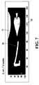
- FIG. 7shows the processed U ram data of the seven of Spades.
- FIG. 8shows the Scratch ram data of a processed rank and processed suit.
- FIG. 8Ais a CMOS gate based on a fundamental inverter circuit.
- FIG. 8Bis a CMOS gate expanded into NOR and NAND structures.
- FIG. 8Cillustrates an inverted structure
- FIG. 8Dillustrates B-series CMOS gates.
- FIG. 8Eillustrates a bilateral switch CMOS gate.
- FIG. 9shows a cutaway view of the side of a dealing shoe employing CMOS sensing according to the invention.
- FIG. 10shows a schematic cross-section of a dealing shoe having a card reading and buffer area.
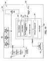
- FIG. 11shows a top cutaway view of one embodiment of a dealing shoe of FIG. 1 according to the present invention.
- FIG. 12shows selected coordinates in a CMOS scanning field.
- FIG. 13shows a series of stored images and a cross correlation outcome of different suits.
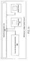
- FIG. 14shows a block diagram of a Baccarat Intelligent System which uses a mechanized shoe with CMOS reading capability.
- FIG. 15shows a schematic diagram of a second Baccarat System using CMOS sensing and a non-mechanized shoe.
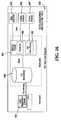
- FIG. 16shows a schematic of how data acquired by a Baccarat System using CMOS sensing is collected and accessed.
- CIScontact image sensor
- line scan arrayAs described in pending U.S. patent application Ser. No. 11/152,475, filed Jun. 13, 2005. The content of this disclosure is hereby incorporated by reference in its entirety.
- the CIS arrayis used to output 1-dimensional line scan data as a vector, and hardware (such as ASIC or preferably an FPGA) is used to transform the vectors to information signals conveying rank and suit information.
- the binary data collected by the CIS moduleis not image data (not 2-dimensional).
- the acquired vector data(or a signal vector) is compared with known (high quality) reference vectors, and the known reference vector with the highest correlation to the acquired signal vector identifies suit or rank and the hardware component can initiate sending of rank and suit information to a data storage medium or processor.
- the present CMOS reading system with FPGA logic control circuitcan be incorporated into a card handling device such as a baccarat shoe.
- the shoeis then able to read and report the rank and suit of each playing card that is dealt, determine the winner during the dealing process and record each card, the reconstructed hands and the outcome of the game (Player/Banker/Tie).
- Systems of the present inventionmay include a display that is able to display multiple rounds of play and the result of each round. It can display the result by a player-viewable reader board and send all of the game information to a casino database through a network.
- the proposed devicecan be used as a stand-alone image reading device for playing cards and it can replace camera/imaging/processor systems presently used by in delivery shoes, discard racks, deck checking and sorting devices and shufflers with reading capacity.
- Additional features proposedenable reading of different card images without precisely aligning the CMOS array or elements with each card (by using column sums of selected indices of signals, and the location of symbols). Communication may be through a digital output port or other known means.
- the output of an exemplary CMOS black and white cameracan be classified as having a series of gray scale output values between 255 (white) and 0 (black) or any other linear or exponential scale.
- the CMOS sensorprovides a representation of the 2-dimensional space by providing a continuous series of Vectors derived from a single card that are correlated with known reference vectors through the hardware (e.g., ASIC or FPGA) and the closest correlation results in an identification of the suit and rank of the card.
- the present inventionis a card reading apparatus that is capable of reading card rank, suit or both rank and suit.
- the systemreads standard cards that do not have special markings.
- the apparatusincludes at least one complementary metal oxide semiconductor (CMOS).
- CMOScomplementary metal oxide semiconductor
- the sensorgenerates signals when a playing card is moved over the sensor. Although the sensor is capable of sensing stationary cards, a preferred sensing occurs while the card is in motion.
- the inventionalso includes the use of hardware component, capable of receiving signals from the sensor, and identifying rank and/or suit.
- the hardware componenttransmits identified the rank and/or suit symbol in real-time to an external device such as a processor.
- the sensoris preferably a black and white CMOS sensor, and data from the sensor comprises grey scale data from the scanned image.
- the gray scale datais converted to binary data either in the hardware component or on the CMOS sensor board.
- the hardware component of the present inventionincludes an FPGA, ASIC or other equivalent device capable of being configured to identify rank and/or suit of cards. Also included is a microprocessor with associated memory. The FPGA receives the reference vectors on power up from the associated memory and uses the reference vectors to determine rank and suit identification.
- CMOS sensing system of the present inventionis in combination with a mechanized dealing shoe.
- the sensing systemin its broadest aspect includes a CMOS sensing array and a FPGA logic circuit that is capable of converting signals from the CMOS sensor into a vector array and compare the vector array to stored vectors to determine rank and or suit of cards.
- the present dealing shoeis implemented specifically for use in the play of casino table games, and especially blackjack (or Twenty-One), and Baccarat.
- the card reading system of the present inventionprovides card rank and or suit reading without greatly increasing the space on the casino table top as compared to a standard dealing shoe.
- the mechanized shoeprovides cards securely to a delivery area and can read the cards in one or more various positions within the shoe, including, but not exclusively a) as they are withdrawn, b) before they are actually nested in the card delivery area, c) when they are first nested in the card delivery area and d) in an area between the card delivery and card withdrawal areas.
- the card reading informationis either stored locally or transferred to a central computer for storage and/or evaluation.
- the cardspreferably may be, but are not required to be mechanically transferred from a point of entry into the dealing shoe to the card delivery area, with a buffer area in the path where at least some cards are actually held for a period of time.
- the cardsare preferably read in the buffer area, before they are delivered into the card delivery area.
- the output from the CMOS sensormay be processed by an FPGA, an ASIC circuit or other equivalent device.
- An ASICis Application-Specific Integrated Circuit, a chip designed for a particular application. ASICs are built by connecting existing circuit building blocks in new ways. Since the building blocks already exist in a library, it is much easier to produce a new ASIC than to design a new chip from scratch.
- FPGAsare field programmable gated arrays, which are a type of logic chip that can be configured after manufacturing.
- An FPGAis similar to a programmable logic device (PLD), but whereas PLDs are generally limited to hundreds of gates, FPGAs support thousands of gates. They are especially popular for prototyping integrated circuit designs. Once the design is set, hardwired chips may be produced at a lower cost. Once a FPGA is programmed, the device behaves as a hard wired circuit. FPGA's do not execute code, and this is an important point in distinguishing FPGA functionality from that of a processor.
- CMOS sensor 12As part of an imaging module 10 as sown in FIG. 1 .
- the modulemay comprise either two related units (the CMOS sensor itself 12 and a separate FPGA logic circuit 14 which receives and acts upon raw signals or data from the CMOS camera), or an integrated system with the CMOS camera and logic/intelligence/functions of the FPGA combined into the single unit.
- An optical position sensor 18may or may not be provided to initiate the capture of data from the sensor array 12 , because the array 12 is typically always sensing.
- the CMOS module 10may also include one or more LED light sources (not shown) to illuminate areas being scanned.
- CMOS Module of the present inventionshould have the following design attributes:
- the FPGAField Programmable Gated Array
- the FPGA moduleincorporates a power supply, communications capability, hardware algorithm implementation ability and data storage capability. It is connected to a sensor module, e.g., via physical connections such as a 20 pin cable.
- Template matchingworks by comparing the cross correlation values of two independent matrices where the cross correlation of two matrices A and B is defined as:
- mismatchis when the system sees a diamond and a heart as identifiable. When a diamond is overlaid on a heart, the measure of match can be nearly identical. The sum of matches for the diamond and heart can actually exceed the sum of matches for a diamond and a diamond template if there is any distortion in the acquired image.
- the templateis typically shifted over the entire ‘area’of an acquired image. It can be shown mathematically that if the matrix is converted into a single 1-D vector, shifting the template around on an image is as simple as shifting the index of the known vector being summed with respect to the corresponding index of the unknown vector.
- CMOS arraycan generate a 1-D signal representative of the scanned card.
- An optical position sensormay be provided to alert the system of the need to capture data by the CMOS array.
- a series of 1-D signals representative of a card passed over its surfaceis then generated.
- ranksare identified separately from suits and in the second, all 52 cards are identified separately, each by rank and by suit.
- an optical position sensor 18initiates the acquisition of data by the CMOS array 12 and the output from the array is sent to the FPGA 14 where the vector set is compared with known vectors to identify card rank and suit.
- a reference vector set for each suit and each rankis stored in the FPGA.
- Black and white CMOS camerastypically output grey-scale values in 8 or 16 bit format. Binary conversion of the grey-scale value is then performed within the FPGA by a simple thresholding method where everything below a certain value is assigned a 0 and everything above is assigned a value of 1. This conversion is possible because color is not needed as a distinguishing factor in determining rank and/or suit.
- CMOS 640 ⁇ 480 black and white arraywas selected, as greater detail is not needed to accurately identify rank and suit.
- the array formatis shown in FIG. 2 .
- the arrayis designed to operate in a QVGA (Quarter VGA) mode such that the resolution is only 320 ⁇ 240.
- QVGA modeis one preferred mode used for card identification (As previously noted, arrays as small as 48 ⁇ 144 or even smaller will suffice for card identification.)
- the origin of the output signalis defined at point (0,0) 21 .
- h and v directionsare defined.
- the arrayis able to output a signal representative of a smaller portion 20 of the entire array 22 if set up properly in the array controller.
- This smaller portion referred to as the window 20is shown in the diagram.
- the smaller window 20is defined in the camera operation setup and for the purposes of this application, a set of registers holds the starting points 24 for the window, known as h_start and v_start.
- the window sizeis defined by h_lines and v_lines.
- a smaller windowcan be outputted that starts at a point (h_start, ⁇ _start) and has a size in pixels of h_lines*v_lines is shown.
- the arraycan look at a selected region within the larger array by simply setting its start points and size.
- This windowing approachis advantageous to compensate for different card types and variability of array placement during the manufacturing process.
- FIG. 3shows an example card 26 positioned over the array window 20 .
- the cardis shown face-up for illustration only. During scanning, the card face is position face down over the window 20 . Only a small portion of the card with rank and suit information need be detected so the window position and size is set appropriately for a given card type.
- an optical sensor 18senses the presence of a card.
- a pair of LED object sensors 28(shown in FIG. 1 ) senses when the card has passed completely over the CMOS sensor, turning the data acquisition off.
- the FPGAcollects data again from the CMOS sensor.
- a signalis acquired that represents the card image positioned over the window. However, the signal is not reconstructed into a 2-D image, it is stored as a 1-D vector in memory U ram.
- the stored signalwould appear something like that shown in FIG. 4 where the upper left corner 30 of a typical playing card 30 appears.
- region of interest 32 and 34are identified.
- First a region of interest 32is for the card rank is defined and second, region of interest 34 is for the card suit.
- the region of interest for eachshould be large enough to completely contain the rank or suit symbol with some additional area or ‘padding’ to account for variability in the acquired signal and variability in card position.
- FIG. 5shows an example of a method of defining regions of interest.
- two regions 32 and 34are defined, one that contains the card rank symbol 32 and the other that contains the card suit symbol 34 .
- the size of the regionsare defined by first the number of vertical lines required. This is referred to as v_depth 36 . Then the depth of the rank and the suit regions are identified as rank_depth 38 and suit_depth 40 .
- the sizesare settable registers in the FPGA to allow identification of differently sized rank and suit symbols found on different styles and brands of cards.
- FIG. 5Bshows the position of the lines.
- a line v_split_start 40is defined as the vertical line position to locate one side of the region of interest.
- rank_split_start 42 and suit_split_start 44are defined to locate the regions of interest precisely
- a series of sumsmay be performed on the acquired signal.
- Each of the horizontal lines his summed and stored in memory as dob_v.
- An algorithmlooks for the location of v_split_start by starting at v_look_start 46 and looking for the minima throughout the range set by v_look_depth 48 .
- Several parametersare tunable such as the minimum threshold set in register v_threshold and the minimum width of the minima set in register v_width.
- the FPGAAfter locating the line v_split_start 40 , the FPGA then generates the column sum dob_h and stores it in memory. A similar algorithm locates the point suit_split_start 44 . The value rank_split_start 42 is then easily generated from suit_split_start 44 ⁇ rank_depth 38 . All the values are stored to registers.
- FIG. 6shows and example of reconstructed images from signals from parsing the U_ram contents into scratch_ram.
- the previous sectiondescribed the FGPA operation to acquire a signal from a CMOS array and manipulate the signal.
- This sectionshows examples of such an acquisition. Acquisition is triggered when a pair of LED sensors 28 indicate a card has been removed and then an optical sensor 18 indicates another card is present ( FIG. 1 ).
- the array outputundergoes a binary conversion inside the FPGA, or alternately, in the sensor.
- the array outputis an 8 bit value and a conversion from the 8 bit value to 0 or 1 is made at a threshold level set by register threshold. The conversion may or may not be inverted.
- When the white sections of the cardare converted to black (or 0) levels. This assists the template matching process.
- the images themselvesare mirror images of cards as we see them because of how the array is mounted and the signal reconstructed. The alignment makes no difference to the identification algorithm.
- FIG. 7shows a series of acquired signals that have been downloaded and reconstructed into 2-D images outside the FPGA to demonstrate accurate symbol identification.
- the Figureshows the large variation in location present in the shoe that necessitated the previously described method of locating first minima along the horizontal lines and then minima along the vertical lines. Additionally, face cards such as the Queen and Jack show additional information 51 from the artwork in the middle of the card. Again, this is filtered out of the U_ram signal when it is parsed into the scratch_ram.
- the rank symbol 50is a mirror image of the number 7.
- the suit symbol 52is symmetrical so the scanned object looks identical to the acquired signal.
- FIG. 8shows the data sample from FIG. 7 after it has been parsed into scratch_ram for identification.
- the modulemay be implemented, for example, using a commercially available FPGA coupled with an 8 bit microprocessor, and optionally coupled to object present sensing devices for activating the acquisition data.
- the XilinxTM XC3S1000 FPGAcontains 14 block RAMs available for high speed read/write operations. This FPGA is available from XILINX of www.xilinx.com.
- the following operationis specific to implementing the present 2-D cards sensing array in a mechanized shoe.
- the FPGA status registerprovides information on the current state of the FPGA.
- card_id_read lockup lockup -indicates FPGA locked up and requires reset.
- card_id_read -indicates a card has been read pic_done - indicates a picture is acquired
- FSM_idle -indicates FPGA master FSM in idle mode motion_reverse - indicates a card has come partially out of the shoe and moved back into shoe
- multi_card_error -indicates a card has been pulled to soon after last card to have been read properly
- Rb_trigger rb_ctl rb_run rb_run -enables FSM to run rb_ctl - lets rabbit take control of FSM rb_trigger - rabbit triggers and acquisition and ID rb_wr_mem - allows rabbit to write to memory rb_rd_ram - allows rabbit to read RAM rb_status_clr - clears status register rb_wr_ram - allows rabbit to write to RAM read_dist_ram - allows rabbit to read distributed RAM
- shoe I/O shoe_IO(Post 0x81) Bit 7 6 5 4 3 2 1 0
- CMOS I/O CMOS_IOPost 0x86 Bit 7 6 5 4 3 2 1 0 Use opt_srom_ld opt_rab_ctl optRST cisLEDon optNCS optNCS - cisLEDon - optRST - opt_rab_ctl - opt_srom_ld -
- the imager 122may be located near the card exit 136 of a mechanized shoe 2 .
- the sensormay be located within the buffer area, such as in area 123 .
- the sensor 122is connected to the FPGA logic circuit (not shown) inside the casing of the shoe 2 .
- the imager 122acquires data from each card being dealt during the game and the FPGA transmits the image information to an external PC (not shown).
- the FPGAdetermines the rank and or suit of each card.
- the imager 122 and FPGAare located internal to the shoe and the output of the FPGA contains a rank and or suit signal for each card dealt.
- the preferred CMOS imaging systemgathers light, white or preferably green LEDs, and directs the light at the original document being scanned.
- a color-reading CMOS sensoris not required, as black-and-white images of the scans are sufficient to identify suit and rank.
- the light that is reflected from the original imageis collected by a lens and directed at an image sensor array that rests just under the document being scanned. The sensor then records signals according to the intensity of light that hits the sensor.
- a CMOS scanneris more compact than a CCD scanner and can be used in smaller products than CCD scanning technologies.
- CMOS scannersalso require less power than CCD scanners and often can run off battery power or the power from a USB port.
- CCD scannersrequire more power but produce higher-resolution scans. The resolution provided by a CCD scanner is more resolution than is needed for card rank and suit identification.
- CMOSis an abbreviation for Complementary Metal Oxide Semiconductor.
- CMOSis a widely used type of semiconductor.
- CMOS semiconductorsuse both NMOS (negative polarity) and PMOS (positive polarity) circuits. Since only one of the circuit types is powered up at any given time, CMOS chips require less power than chips using just one type of transistor.
- CMOS image sensorscan be made at standard manufacturing facilities that produce 90% of all semiconductor chips, from powerful microprocessors to RAM and ROM memory chips. This standardization results in economies of scale and leads to ongoing process-line improvements.
- CMOS processesmoreover, enable very large scale integration (VLSI), and this is used by “active-pixel” architectures to incorporate all necessary camera functions onto one chip.
- VLSIvery large scale integration
- CMOS architecturesconsume much less power—up to 100 ⁇ less power—than their CCD counterparts. This is a great advantage in battery-dependent portable applications, such as laptop computers, hand-held scanners, and video cell phones.
- CCD systemstend to be inherently power hungry. This is because CCDs are essentially capacitive devices, needing external control signals and large clock swings (5-15 volts) to achieve acceptable charge transfer efficiencies. Their off-chip support circuitry dissipates significant power.
- CCD systemsrequire numerous power supplies and voltage regulators for operation, whereas active-pixel sensors use a single 5-volt (or 3.3-volt) supply, reducing power-supply inefficiency.
- a CCD systemtypically requires 2-5 watts (digital output), compared to 20-50 milliwatts for the same pixel throughput using an active-pixel system.
- a CMOS digital camera system operating from a NiCd camcorder batterycould operate for a week, while a CCD arrangement would drain the battery in a few hours.
- both the photo detector and the readout amplifierare part of each pixel. This allows the integrated charge to be converted into a voltage inside the pixel, which can then be read out over X-Y wires (instead of using a charge domain shift register, as in CCDs).
- This column and row addressabilitysimilar to common DRAM, allows for window-of-interest readout (windowing), which can be utilized for on-chip electronic pan, tilt, and zoom. Windowing provides much added flexibility in applications that need image compression, motion detection, or target tracking.
- the RMS input-referred noiseis comparable to the very high-end (and expensive) CCDs. Both technologies provide excellent imagery compared with other CMOS image sensors. Active-pixel architectures use intra-pixel amplification in conjunction with both temporal and fixed-pattern noise suppression circuitry (i.e., correlated double sampling), which produces exceptional imagery in terms of dynamic range (a wide ⁇ 75 dB) and noise (a low ⁇ 15 e-RMS noise floor), with low fixed-pattern noise ( ⁇ 0.15% sat). Active-pixel sensors achieve a quantum efficiency (sensitivity) that is comparable to high-end CCDs, but, unlike CCDs, they are not prone to column streaking due to blooming pixels. This is because CCDs rely on charge domain shift registers that can leak charge to adjacent pixels when the CCD register overflows, causing bright lights to “bloom” and leading to unwanted streaks in the image.
- the signal chargeis converted to a voltage inside the pixel and read out over the column bus, as in a DRAM.
- the sensorshave built-in anti-blooming protection in each pixel, so that there is no blooming. Smear, caused by charge transfer in a CCD under illumination, is also avoided.
- CMOS active-pixel designsare inherently fast, which is a particular advantage in machine-vision and motion-analysis applications.
- Active pixelscan drive an image array's column buses at greater speeds than is possible on passive-pixel CMOS sensors or CCDs, and on-chip analog-to-digital conversion (ADC) eases the driving of high-speed signals off-chip.
- ADCanalog-to-digital conversion
- a separate benefit of on-chip ADCsis the output signal's low sensitivity to pick-up or crosstalk. This facilitates computer and digital-controller interfacing while adding to system robustness.
- CMOS active-pixel architecturesallow signal processing to be integrated on-chip. Beyond the standard camera functions—AGC, auto-exposure control, etc.—many higher-level DSP functions can be realized. These include anti-jitter (image stabilization) for camcorders, image compression (before and after readout), color encoding, computer data bus interface circuits, multi-resolution imaging, motion tracking for perimeter surveillance (“smart image sensing”), video conferencing, and wireless control.
- CMOS logicis based on the use of complementary MOS transistors to perform logic functions with almost no current required. This makes these gates very useful in battery-powered applications. The fact that they will work with supply voltages as low as 3 volts and as high as 15 volts is also very helpful.
- CMOS gatesare all based on a fundamental inverter circuit.
- Both transistorsare enhancement-mode MOSFETs; one N-channel with its source grounded, and one P-channel with its source connected to +V. Their gates are connected together to form the input, and their drains are connected together to form the output.
- the two MOSFETsare designed to have matching characteristics. Thus, they are complementary to each other. When the transistor is off, their resistance is effectively infinite; when on, their channel resistance is about 200 ⁇ . Since the gate is essentially an open circuit, it draws no current, and the output voltage will be equal to either ground or to the power supply voltage, depending on which transistor is conducting.
- the N-channel MOSFETWhen input A is grounded (logic 0), the N-channel MOSFET is unbiased, and therefore has no channel enhanced within itself. It is an open circuit, and therefore leaves the output line disconnected from ground. At the same time, the P-channel MOSFET is forward biased, so it has a channel enhanced within itself. This channel has a resistance of about 200 ⁇ , connecting the output line to the +V supply. This pulls the output up to +V (logic 1).
- This conceptcan be viewed in FIG. 8B and shown to be expanded into NOR and NAND structures by combining inverters in a partially series, partially parallel structure.
- the circuit shown in the figureis a practical example of a CMOS 2-input NOR gate.
- both P-channel MOSFETswill be turned on, thus providing a connection to +V. Both N-channel MOSFETs will be off, so there will be no ground connection. However, if either input goes high, that P-channel MOSFET will turn off and disconnect the output from +V, while that N-channel MOSFET will turn on, thus grounding the output.
- FIG. 8Cits is shown that the structure can be inverted, as shown to the left.
- a logic 0 at either inputwill force the output to logic 1, but it takes both inputs at logic 1 to allow the output to go to logic 0.
- CMOS totem polesare not made more than four inputs high. Gates with more than four inputs are built as cascading structures rather than single structures. However, the logic is still valid.
- the totem pole structurestill causes some problems in certain applications.
- the pull-up and pull-down resistances at the outputare never the same, and can change significantly as the inputs change state, even if the output does not change logic states. The result is uneven and unpredictable rise and fall times for the output signal. This problem was addressed, and was solved with the buffered, or B-series CMOS gates, shown in FIG. 8D .
- the technique hereis to follow the actual NAND gate with a pair of inverters.
- the outputwill always be driven by a single transistor, either P-channel or N-channel. Since they are as closely matched as possible, the output resistance of the gate will always be the same, and signal behavior is therefore more predictable.
- CMOS gatesOne of the main problems with CMOS gates is their speed. They cannot operate very quickly, because of their inherent input capacitance. B-series devices help to overcome these limitations to some extent, by providing uniform output current, and by switching output states more rapidly, even if the input signals are changing more slowly.
- CMOS gate constructionhas been described here, but one skilled in the art is available of the design flexibility in CMOS and would not interpret this description as limiting practice of the technology to the specific embodiments shown.
- CMOScomplementary metal-oxide-semiconductor
- input protection circuitsto prevent input voltages from becoming too high.
- these protection circuitsdo not affect the logical behavior of the gates, so the description of the protection circuit has been omitted.
- FIG. 8EOne type of gate, shown in FIG. 8E , is unique to CMOS technology. This is the bilateral switch, or transmission gate. It makes full use of the fact that the individual FETs in a CMOS IC are constructed to be symmetrical. That is, the drain and source connections to any individual transistor can be interchanged without affecting the performance of either the transistor itself or the circuit as a whole.
- both transistorsWhen the N- and P-type FETs are connected and their gates are driven from complementary control signals, both transistors will be turned on or off together, rather than alternately. If they are both off, the signal path is essentially an open circuit—there is no connection between input and output. If they are both on, there is a very low-resistance connection between input and output, and a signal will be passed through.
- a battery power supplycould be used to power the device.
- the card sensing system of the present inventionmay be used a variety of ways in order to be useful in providing card rank and or suit information in real time from a live table game.
- Nonlimited examples of uses of the card rank and/or suit identification device of the present inventioninclude a) as a table-top card sensing system, b) as part of a mechanized shoe that moves cards within the shoe, c) as part of a standard shoe with card reading sensor at the exit end, d) as part of a shuffler, including a continuous shuffler, a batch shuffler and a hand-forming shuffler, e) as part of a deck verification device, and f) as part of a discard rack capable of moving cards over a sensor.
- FIG. 9shows a mechanized card delivery shoe 102 according to the present invention.
- the card delivery shoe 102has a card infeed or card input area 104 which is between motor 119 and the rear panel 112 of the card delivery shoe 102 .
- a belt driving motor 106drives a belt 108 that engages pick off rollers 110 . These pick off rollers 110 pick off and move individual cards from within the card infeed area 104 .
- a belt driving stepper motor 106is shown but other motor types such as gear drives, axle drives, magnetic drives and the like may be alternatively used.
- the pick off rollers 110drive individual playing cards (not shown) into a gap 114 having a deflector plate 115 to direct cards individually through the gap 114 to engage brake rollers 116 .
- the brake rollers 116 a , 116 bcontrol the movement of individual cards into the card staging area 134 .
- the brake rollers 116 a , 116 bare capable of becoming free-turning rollers during a card jam recovery process so that little or no tension is placed on a card as it is being moved by the system or manually to free a jam. A simple gear release or clutch release can affect this function.
- Speed up rollers 117 a , 117 bapply tension to a card to move it more deeply into the card staging area 134 .
- the speed up rollerscan and may turn faster then the braking rollers 116 a , 116 b , and the speed up rollers 117 a , 117 b may be driven by a separate motor 119 and belt drive 121 .
- a card path and direction of movement Ais shown through the card staging area 134 . As individual cards are passed along the card path A through the card staging area 134 , there are card presence sensors 118 , 120 , located at various intervals and positions to detect the presence of cards to assure passage of cards and/or to detect stalled or jammed cards.
- the path A through the card storage area 134is in part defined by speed-up rollers 117 a , 117 b or rear guide rollers 124 a , 124 b and forward guide rollers 126 a , 126 b which follow the brake rollers 116 a , 116 b and then the speed up rollers 117 a , 117 b .
- One form of a buffer area 148is established by the storing of cards along card path A. As cards are withdrawn from the delivery end 136 of the delivery shoe 102 , additional cards are fed from the buffer area 148 into the card feed chute 146 into the delivery end 136 .
- the mechanized delivery shoeis preferred, but a purely mechanical shoe, little different from standard non-imaging shoes used in casinos, may be provided with the imager described herein and the signals provided there from sent to hardware that transforms the signals, software that processes the signals, intermediate storage systems and/or final storage systems for use at appropriate times.
- the descriptionwill emphasize the delivery shoe (which may also be the output element of a shuffler) that automatically moves and delivers cards, only because that is a preferred embodiment, not because that is the only format of shoe that can be used with the described imaging technology.
- the jam recoverymay be based upon an identified (sensed) position of jam or may be an automated sequence of events. Where a card jam recovery is specifically identified by the sensed position of a jammed card in the device (and even the number of cards jammed may be estimated by the dimensions of the sensed image), a jam recovery procedure may be initiated at that specific location.
- a specific location in FIG. 9 within the dealing shoee.g., between and inclusive of rollers 116 a , 116 b and 117 a , 117 b will be discussed from an exemplary perspective, but the discussion relates to all other positions within the device.
- a cardis sensed (e.g., by sensors 118 and/or 120 ) as jammed between rollers 116 and 117 (e.g., a jam occurs when cards will not move out of the position between the rollers within a specified time limit and/or cards refuse to be fed into that area)
- a jamoccurs when cards will not move out of the position between the rollers within a specified time limit and/or cards refuse to be fed into that area
- one of a various number of proceduresmay be initiated to recover or remove the jam.
- the various procedureswhich are discussed by way of non-limiting examples include at least the following.
- the rear-most set of rollers ( 116 a and 116 b )may reverse direction (e.g., 116 a begins to turn clockwise and 116 a begins to turn counterclockwise) to remove the jammed card from between the rollers ( 116 a and 116 b ) and have the card extend backwards into the space 114 , without attempting to reinsert a card into the stacking area 4 .
- the reversed rotationmay be limited to assure that the card remains in contact with the rollers 116 a and 116 b , so that the card can be moved back into progression through the dealing shoe.
- An optional part of this reversalcan include allowing rollers 117 a and 117 b to become free rolling to release contact and tension on the card during the reversal.
- the reversed rotationmay be smoothly run or episodic, attempting to jerk a jammed card from its jammed position. If that procedure does not work or as an alternative procedure, both sets of rollers 116 a , 116 b and 117 a , 117 b may reverse at the same time or in either sequence (e.g., 116 a , 116 b first or 117 a , 117 b first) to attempt to free the jam of a card.
- rollersWhen one set of rollers only is turning, it is likely to be desirable to have the other set of rollers in the area of the jam to become free rolling. It is also possible to have the rollers automatically spaced further apart (e.g., by separating roller pairs to increase the gap in the potential nip between rollers) to relieve tension on a card and to facilitate its recovery from a jam.
- the adjacent pairs of rollerse.g., 116 a , 116 b and 117 a , 117 b
- the recovery processmay have the rollers act as a) ( 116 - 117 ) at the same time in the same direction), b) ( 116 - 117 ) at the same time in the opposite directions to assist in straightening out cards, c) ( 116 then 117 ) to have the rollers work sequentially, d) ( 117 then 116 ) to have the rollers work in a different sequence, e) 116 only for an extended time, and then 117 operating alone or together with 116 , f) 117 only for an extended time or extended number of individual attempts and then 116 for a prescribed time, etc.
- a non-active rollerone that is not attempting to drive or align cards
- Individual playing cardsmay be read at one or more various locations within the card delivery shoe 102 .
- the ability to provide multiple read locationsassures performance of the shoe, while other card delivery trays with read capability usually had a single reading position at the point where and when cards were removed from the shoe for delivery to players.
- the card presence sensors 118 , 120may also have card reading capabilities, and other card reading sensors may be present as elements 132 , 140 and 142 .
- Element 138may be present as another sensing element or a card value (and possibly suit) reading element without the presence of sensor 122 or in combination with sensor 122 .
- the sensor 138such as a CMOS sensor with FPGA control logic functions as a card reading element, it can read the cards as they are positioned within the card buffer area 137 , rather then as the cards are removed from the card delivery end 136 .
- Informationmay be read by the card reading sensor 138 by either continuous reading of all image data in the card pre-delivery or buffer area or by triggered on-off imaging of data in a specific region of cards 139 as a card 141 is within the pre-delivery area 137 .
- card presence sensor 122may activate sensor 138 .
- This sensoris preferably a CMOS sensor with FPGA control logic.
- a light source(not shown) may be provided to enhance the signal to the sensor 138 .
- One preferred light sourceis a green diode. The green diode causes the red print on the cards to appear black to the CMOS sensor.
- That specific region of cardsis preferably a corner of the card 141 wherein complete value information (and possibly suit information) is readable on the card, such as a corner with value and suit ranging symbols on the card. That region could also be the entire face of the card, or at lease 1 ⁇ 2 of the card (lengthwise divided). By increasing the area of the region read more processing and memory is required, but accuracy is also increased.
- Accuracycould also be increased, by reading the upper right hand corner of the card and lower left hand corner, since both of those locations contain the rank and suit of the card. By reading 2 locations on the card, and comparing the derived rank and suit data, correct identification can be confirmed.
- By using on-off or single shot imaging of each card 141the data flow from the sensor/card reading element 138 is minimized and the need for larger memory and data transmission capability is reduced in the system.
- Cardsmay be buffered or staged at various points within the dealing shoe 102 , such as where restrained by rollers 126 a , 126 b so that cards partially extend towards the chute 146 past the rollers 128 a , 128 b on plate 143 , or staged between rollers 124 a , 124 b and 126 a , 126 b , between rollers 117 a , 117 b and 124 a , 124 b , between rollers 116 a , 116 b and 117 a , 117 b and the like.
- Cardsmay partially overlap in buffering as long as two or more cards are not present between a single set of nip rollers (e.g., 126 a , and 126 b ) where nip forces may drive both cards forward at the same time.
- nip rollerse.g., 126 a , and 126 b
- rear panel 112may have a display thereon for displaying information or data, particularly to the dealer (which information would be shielded from players as the rear panel 112 would primarily face the pit and be shielded from players' view.
- a more ergonomic and aesthetic rear surface 150is shown having a display 152 that is capable of providing alphanumerics (letters and numbers) or analog or digital images of shapes and figures in black-and-white or color.
- the displaymay give messages as to the state of the shoe, time to number of cards dealt, the number of deals left before a cut card or virtual cut card is reached (e.g., the dealing shoe identifies that two decks are present, makes a virtual cut at 60 cards, and based on data input of the number of players at the table, identifies when the next deal will be the last deal with the cards in the shoe), identify any problems with the shoe (e.g., low power, card jam, where a card is jammed, misalignment of cards by rollers, and failed element such as a sensor), player hands, card rank/suit dispensed, game outcome information, game play instructions and the like.
- problems with the shoee.g., low power, card jam, where a card is jammed, misalignment of cards by rollers, and failed element such as a sensor
- player handscard rank/suit dispensed, game outcome information, game play instructions and the like.
- the rear surface 150Also on the rear surface 150 are two lights 154 and 156 , which are used to show that the shoe is ready for dealing (e.g., 154 is a green light) or that there is a problem with the dealing capability of the shoe (e.g., 156 is a red light).
- the memory board 158 for the card reading sensor 138is shown with its information outlet 144 shown.
- the card infeed area 104By having the card infeed area 104 provide the cards in at least a relatively vertical stack (e.g., with less then a 60° slope of the edges of the cards away from horizontal), length of the delivery shoe 102 is reduced to enable the motor driven delivery and reading capability of the shoe in a moderate space.
- No other card delivery shoesare known to combine vertical card infeed, horizontal (or approximately horizontal ⁇ 40° slope or ⁇ 30° slope away from horizontal) card movement from the infeed area to the delivery area, with mechanized delivery between infeed and delivery.
- the motor drive feed from the vertical infeedalso reduces the need for dealers to have to jiggle the card tray to keep cards from jamming, slipping to undesirable angles on the chutes, and otherwise having to manually adjust the infeed cards, which can lead to card spillage or exposure as well as delaying play of the game.
- Certain aspects of the inventionmay alternatively be described as a card storage shoe comprising a card infeed area where an approximately vertical set of cards can be seated.
- the shoecould have a card moving element that moves one card at-a-time from the approximately vertical set of cards.
- Therecould be an automatic mechanical transporting system for horizontally transporting individual ones of cards moved from the vertical set of cards to a card delivery area.
- Thereis preferably (but optionally) a card reading system that reads at least one of suit, rank and value of cards before read cards become stationary in the card delivery area.
- a buffer areais present between the card infeed area and the card delivery area and at least some cards remain stationary for a time in the buffer area before being delivered to the card delivery area.
- Cardsmay be read, for example, entering or while stationery in the buffer area.
- only one cardis present in the card buffer area at any time. It is one aspect of an embodiment of the invention for cards to be read in the shoe after they leave the card buffer area but before they are completely stationary in the card delivery area. They may be read when stationery in the card buffer area, but not in the card delivery area.
- a sensor-readere.g., a camera or any other form of image detector
- read cardsdiscontinuously when the sensor-reader is triggered by a card detection sensor in the shoe.
- a method for providing a card to a dealer for manual delivery of the cards by a dealercomprising:
- the methodmay include placing the set of cards in an approximately vertical stack in the card feed area. At least one card from the set of cards may be moved to a buffer area between the infeed area and the card delivery area, and at least one card may remain stationary within the buffer area until the card delivery area is sensed to be empty of cards.
- the methodmay be generated by a sensor in the card delivery area indicating that an additional card is desired in the card delivery area.
- the signalmay be generated by a sensor in the card delivery area indicating that no cards are present in the card delivery area.
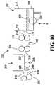
- FIG. 10shows an alternate embodiment for internal card buffering and card moving elements of the card delivery shoe 200 .
- a card infeed area 202is provided for cards 204 that sit between walls 211 and 212 on elevator 206 which moves vertically along path B.
- a pick-off roller 208drives cards one-at-a-time from the bottom of the stack of cards 204 through opening 210 that is spaced to allow only one card at a time to pass through the hole 210 .
- the individual cardis fed into the nip area 214 of the first speed control or guide roller pair 216 and then into the second guide roller pair 218 .
- the cards (one-at-a-time) passing through rollers 218are shown to deflect against plate 220 so that cards flare up as they pass into opening 222 and will overlay any cards (not shown) in card buffer area 224 .
- a second pick-off roller 226is shown within the buffer area 224 to drive cards one-at-a-time through opening 228 .
- the individual cardsare again deflected by a plate 230 to pass into guide roller pair 232 that propels the cards into the delivery area (not shown) similar to the delivery area 136 in FIG. 9 .
- Card reading elementsmay be positioned at any convenient point within the card delivery shoe 200 shown in FIG. 10 , with card reading elements 234 and 236 shown as exemplary convenient locations.
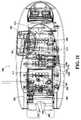
- FIG. 11shows a top view of a mechanized dealing shoe 300 of an embodiment of the present invention.
- a flip up door 302allows cards to be manually inserted from above into the card input area 304 .
- the sets of pick-off rollers 308 and 310are shown in the card input area 304 .
- the position of the sensors 318 a and 318 b and 320 a and 320 bare shown outwardly from the sets of five brake rollers 316 and five speed up rollers 317 .
- the sensorsare shown in sets of two sensors, which is an optional construction and single sensors may be used.
- the dual set of sensors(as in 320 a and 320 b ) are provided with the outermost sensor 320 b providing simply sensing card presence ability and the inner innermost sensor 320 a reads the presence of card to trigger the operation of the camera card reading sensor 338 that reads at least value, and optionally rank, and suit of cards.
- the sensor 320 aalternatively may be a single sensor used as a trigger to time the image sensing or card reading performed by CMOS/FPGA imaging system 338 as well as sensing the presence of a card.
- An LED light panel 343 or other light providing systemis shown present as a clearly optional feature. Examples of suitable LED light sources include white light, blue light and most preferably green light.
- a sensor 346 at the card removal end 336 of the shoe 300is provided.
- the finger slot 360is shown at the card delivery area 336 of the shoe 300 .
- the lowest portion 362 of the finger slot 360is narrower then the top portion 364 of the finger slot.
- the walls 366may also be sloped inwardly to the shoe and outwardly towards the opening 360 to provide an ergonomic feature to the finger slot 360 .
- the inventordevised a way to look for location of the rank and suit information by using column sums of selected indices of the signal, which can work even when different brands of cards with different symbol images are used, without the necessity of training the system or redesigning FPGAs to match specific symbols. This is a distinct advantage over most disclosed systems that require specially marked cards or training for each type of card used. Location of the rank/suit symbols is extracted from information about where the sums are low. This feature allows the sensed objects to be located in different areas in the larger sensing area and allows the device to successfully locate and compare the vectors.
- this techniquemay be implemented by utilizing an optical position sensor 18 that resides on the CMOS module 10 .
- the optical card presence sensor 18may sense the presence of a card.
- the sensormay be positioned at a specific location of the device where it can detect the card presence.
- the sensoroutputs data when it senses a card. It communicates with the FPGA 14 via a digital input/output port.
- a second sensor 28senses when the same card is removed.
- the CMOS array 12may reside on the CMOS module 10 .
- the output voltage of the CMOS arrayis an indication of a shade of gray measured on each pixel of the array, since the system is a black and white reading system. Color scanning may be used, is not needed for collecting the desired signals for determining suit and rank.
- the output of the CMOS arrayis converted into binary code in the sensor, in a separate hardware element or in the FPGA and the output would then be a series of numerical values equal to 1 or zero. Any scanned shade of gray is initially represented by a digital signal between 0 and 255 and is then converted to a 1 or a 0.
- One proposed systemscans the entire area of the card face containing the rank and suit symbols one pixel at a time.
- the areais defined by coordinates X and Y.
- the CMOS array 12 and the optical position sensor 18read the x and the y directions accordingly.
- FIG. 12shows the coordinates of the area.
- the systemTo determine card rank and suit, the system must first be trained or hardwired to recognize card rank and suit. To accomplish this, a single vector set for each rank (A, K, Q, J, 10, 9, 8, 7, 6, 5, 4, 3, 2) and a vector set for each suit (Hearts, Clubs, Diamonds and Spades) is scanned, converted to binary values and is saved (e.g., a known reference vector set is saved for each distinct symbol) by acquiring a set of signals during a training phase, or by hardwiring the system based upon a known set of card symbols or using a large tolerance hardwiring for a range of symbols. The signals acquired during training undergo the same binary conversion and are stored.
- a single vector set for each rankA, K, Q, J, 10, 9, 8, 7, 6, 5, 4, 3, 2
- a vector set for each suitHearts, Clubs, Diamonds and Spades
- an unknown vector setis acquired when a triggering signal is detected.
- This unknown vector setmay preferably be the single set of gray scale values, a set of binary values from the individual pixel scans, or be a combination of at least two attributes.
- the triggering signalcan take many forms.
- the triggering mechanismcan be an edge sensor (indicating that a first leading edge of a playing card has passed over an optical or motion sensor, a motion sensor indicating movement of a playing card, an optical present sensor 18 (shown in FIG. 1 ) indicating the presence of optical density other than white (e.g., a card sensor) over an optical sensor, or the like.
- the scanningmay be continuous or may continue on a timed, or sensed (e.g., distance or speed of movement of the card, degree of variation in the signal from the sensor, etc.) basis.
- a fast exposure timeis used such as 1/1000 of a second or less.
- timed triggeringmay be more appropriate.
- the unknown vectoris then correlated with the known vectors to determine a match and identify the card's rank and suit.
- cross correlation of 2D signals A and Bmay be defined as following equation, where ‘A’ is the unknown signal and ‘B’ is the template signal.
- a series of ‘Correlators’is generated in the FPGA that correlates all ranks and suits with the unknown vector either sequentially, or preferably concurrently.
- the unknown vectoris then shifted and a new series of correlations performed.
- the term “shifted”means that the top two values of the series of values that constitutes the entire vector (each being a zero or a 1) is removed from the top of the vector and placed at the bottom of the vector, changing the order of the number pairs in the vector.
- a simple vectormight be the following order pairs:
- the inventororiginally encountered a problem in correctly identifying the suit of the cards using the cross correlation technique: a “diamond” is read as the “heart”. This is because the diamond shape can be fit into the heart shape, see FIG. 13C for illustration. As a result, the diamond shape could have been reported as both heart or a diamond by the FPGA Card Identification Module.
- the inventoruses the error correction function to compares the “un-matched” area 402 of the shapes.
- the error correction functionis defined as the following equation: ⁇ A*B ⁇ A′*B (2)
- the proposed deviceis preferably implemented using FPGA technology (rather than using a an external processor and memory) to improve the speed of identifying cards and to dramatically reduce the cost. Speed is improved because operations are performed in real time with hardware logic circuits, rather than software running on a processor. Costs are reduced because there is no longer any need for complex computational capability.
- the card ID datacan be stored locally by a database storage system, the processor and/or transmitted to a remote location for storage.
- the term camera as generally used hereinis intended to have its broadest meaning to include any component that accepts radiation (including visible radiation, infrared, ultraviolet, etc.) and provides a signal based on variations of the radiation received.
- Thiscan be an analog camera or a digital camera with a decoder or receiver that converts the received radiation into signals that can be analyzed with respect to image content.
- the signalsmay reflect either color or black-and-white information or merely measure shifts in color density and pattern.
- Area detectors, semiconductor converters, optical fiber transmitters to sensors or the likemay be used. Any convenient software may be used that can convert to radiation signals to information that can identify the suit/rank of a card from the received signal.
- lensesmay or may not be needed to focus light, mirrors may or may not be needed to direct light and additional radiation emitters (lights, bulbs, etc.) may or may not be needed to assure sufficient radiation intensity for imaging by the camera.
- a triggering mechanismcan be used to set of the camera shot at an appropriate time when the card face is expected to be in the camera focal area or image plane or location.
- triggerscan include one or more of the following, such as optical position sensors within an initial card set receiving area, an optical sensor, a nip pressure sensor (not specifically shown, but which could be within either nip roller (e.g., 116 or 117 , see FIG. 9 ), edge sensor, light cover sensor, and the like.
- the camerais instructed to time its shot to the time when the symbol containing corner of the card is expected to be positioned within the camera focal area.
- the cardmay be moving at this time and does not have to be stopped.
- the underlying functionis to have some triggering in the device that will indicate with a sufficient degree of certainty when the symbol portion of a moving or moved card will be with the camera focal area.
- a light associated with the cameramay also be triggered in tandem with the camera or imager so as to extend the life of the light and reduce energy expenditure in the system.
- the proposed card delivery devicethat utilizes the card identification method described above in an alternate embodiment is a manual card delivery shoe (not shown).
- the card delivery devicecan deliver single or multiple decks of cards. This is different from the mechanized Shoe as shown in FIGS. 9 and 11 as this shoe does not necessarily have a motor and other mechanical elements and the reading and correlation system is improved there from.
- the imaging systemis arranged so that cards being removed from the shoe are read by a CMOS imaging system of the present invention.
- One preferred embodiment of the delivery shoe, its methods and apparatusmay be generally defined as card delivery shoe having a storage end and a delivery end.
- the shoestores a first set of pre-shuffled cards in the storage end and allows manual removal of cards from the delivery end.
- the lower edges of the cardsrest on a declining surface, whose lowermost edge is at the delivery end of the shoe.
- a block or stopslides along the declining surface, and is positioned nearest the storage end, holding the cards against the delivery end.
- the delivery endmay optionally be equipped with a motor driven shaft bearing a feed wheel (not shown), which moves a card out of the shoe.
- a sensormay provide a signal (to some intelligence or signal receiving function) and power is provided to a motor so that a next card is delivered to the delivery end.
- the cardcan be manually or automatically removed.
- the card delivery shoemay also have at least one sensor that reads card values in the card delivery shoe as each card is removed from the shoe.
- a preferred sensoris the CMOS/FGPA sensor and control logic
- Baccaratis one of the many live table games played in casinos or gaming establishments. Baccarat uses a standard deck of 52 playing cards and is usually dealt from a shoe having multiple decks that have been shuffled together prior to the beginning of play. Poker is usually dealt from a single deck of cards, and blackjack (Twenty-One) is dealt from at least one deck, with up to eight or more decks in a shoe being in common use.
- One set of individual and/or collective primary purposes of the reading suit and or rank of cards in the dealing shoeis to enable:
- the dealing shoe for use with the casino table card gamesmay be integrated with other components, subcomponents and systems that exist on casino tables for use with casino table games and card games.
- Such elementsas bet sensors, progressive jackpot meters, play analysis systems, wagering analysis systems, player comping systems, player movement analysis systems, security systems, and the like may be provided in combination with the baccarat shoe and system described herein.
- Newer formats for providing the electronics and componentsmay be combined with the baccarat system. For example, new electronic systems used on tables that provide localized intelligence to enable local components to function without absolute command by a central computer are desirable.
- the improved Baccarat Intelligent System described herein and shown in FIG. 14may include one card delivery device (preferably a simple shoe) 420 with CMOS sensing, and an internal FPGA logic module and an optional Reader Board/Display Module 422 .
- the individual modulesare connected to a network communication line 424 , and do not communicate directly to other modules.
- the baccarat shoe 420is in two-way communication via standard network communication line 424 , and through this connection, data generated by the shoe 420 is sent to a remote database (not shown) via a network communication line 424 .
- the display module 422is also in two-way communication with the network. It is programmed to display cumulative card rank information for each hand (banker and player) that was transmitted by the baccarat shoe, and other game-related information such as win/loss hits taken, historical win/loss/tie information side bet outcomes and the like.
- An improved card delivery device of the present systemis an 8-deck simple card delivery shoe (not shown).
- the shoelacks mechanical card-moving mechanisms.
- a diagrammatical illustration of the delivery shoe 500is shown in FIG. 15 .
- the simple shoe 500contains the following internal hardware components: CMOS sensor array 522 , a plurality of result indicating lights 536 and buttons 534 , an audio indicator 538 , one logic module 540 , and a LCD display 532 .
- the logic module 540includes a field programmable gated array 524 , and one 8-bit microcontroller 526 .
- the microcontrollerincludes a baccarat hand reconstruction module 528 , a configuration module 530 and a card identification module 542 .
- the CMOS sensor array 522is located near the exit end of the shoe.
- the FPGA 524 and the 8-bit microcontroller 526reside on the logic module 540 .
- This logic module 540replaces the external mini computer needed when a conventional camera is used for card identification and also acts as a game controller and communication channel.
- the CMOS sensor array 522is connected directly to the FPGA 524 .
- the sensor array 522generates an output signal that corresponds to gray scale values detected on the card.
- a card passing through the exit end of the shoetriggers the FPGA to read the output of CMOS sensor array 522 .
- the FPGAis configured to act as a digital signal processor, which transforms the signal into a signal representing card rank and or suit.
- the 8-bit microcontroller 526acts as a system controller and communication channel. It contains three software modules: Card Identification module 542 , the Baccarat Hand Reconstruction module 528 and the Configuration module 530 .
- the Card-ID modulereads the output of the FPGA, compares the signals to stored signals and determines rank and suit. The module also transmits or saves it as appropriate per the configuration.
- the Baccarat Hand Reconstruction modulehas the capabilities of reconstructing the hands and determining the outcome of each round, according to the rules of Baccarat.
- the devicecan be programmed with other game rules to track the play of other games.
- the hand informationis sent out from the logic module as the shoe output via the network communication port.
- the Configuration module 530 in one example of the inventionhas an imbedded web server which gives the user the capability to remotely change the configuration of the Baccarat Hand Reconstruction module, as well as options for the shoe through a web interface and store that information in flash memory of the 8-bit microcontroller.
- the logic module 528controls the buttons 534 , result indicating lights 536 , LCD display 532 , the audio indicator 538 ,
- the LCD display 532is located on the back of the shoe. It displays messages to communicate with users (dealers), helping user to operate the delivery shoe. For example, the display indicates when the dealer must deliver a hit card to a baccarat hand.
- buttons 534There are at least a total of three signal control buttons 534 on the shoe. One of them is located on the front side of the shoe, and the other two are located on the back of the shoe above the LCD. These three buttons are also used as switches.
- the logic moduleissues a command. For instance, the game information will not be displayed until Button A is been pressed, therefore, the dealer can decide the best time to display game result; Button B can be used to set up mode when power up the system; Button C can be used for service mode when powering up the system.
- the functions of these buttonsare customizable, which means they can be programmed differently to meet customer's varied requests.
- the three result indication lights 536are located on top of the shoe.
- a messageis sent from the Baccarat hand reconstruction module to the 8-Bit Micro Controller.
- the 8-Bit microcontrollertriggers the lights to come on/off.
- the light indication featureallows users (casinos) to select different colors when configuring the shoe) to indicate Banker, Player and Tie.
- the typical available colorsare: red, blue, green, yellow and orange.
- the audio indicator 538is also an optional feature. It can be configured to alarm operational errors or shoe malfunctions.
- the events that trigger the alarmare customizable through the user interface of the device. The events include but are not limited to the following:
- the display or “reader board”may be selected from available components.
- the reader boardcontains a processor that is capable of communicating with the network. This non-limiting description is for the ITS module that functions as a game result displaying device.
- this automatic reader board 422receives data directly from the network communication line 424 .
- the messages from the intelligent shoe 420may be broadcasted to the network.
- the display modulecan be programmed to “listen” and react to the state changes of the shoe, and display the outcome of the game automatically.
- a networked-based controllercan also send display commands to the display module 422 .
- the game outcomesare preferably displayed with a time delay or triggered by the dealer pushing a button.
- the amount of the delay timeis variable upon the user's requests.
- historical game resultscan also be displayed, as well as messages, advertising and the like.
- the baccarat system 620can be used as a data acquisition component of a module of a larger casino data acquisition system 600 .
- the collected datacan be used to perform casino table game analysis. Data analysis is possible when multiple data acquisition modules are in communication with a database 680 , preferably on a network, and the information is stored in the database 680 .
- Other data acquisition modules 682 , 684can be connected to the network and data can be transferred to the database 680 via a middleware receiver 686 .
- the middleware receiver 686includes a data receiver 688 and a data pump 690 .
- Datacan be accessed and mined via a local “thin client” application that allows users to view game results remotely on a web enabled devices such as desk top computer, PDA, Black Berry etc. 692 .
Landscapes
- Engineering & Computer Science (AREA)
- Multimedia (AREA)
- Image Analysis (AREA)
- Signal Processing For Digital Recording And Reproducing (AREA)
Abstract
Description
ΣΣA*B−ΣΣA′*B
This error function detects unmatched areas between signals from the imager and predetermined signals, rather than detecting matched areas.
- 1) small 2-Dimensional image arrays, particularly CMOS sensors;
- 2) black and white imaging;
- 3) converting sensor output to binary values so that more sophisticated shading or optical density readings are obviated;
- 4) Simple template matching may be used, rather than elaborate image extraction techniques.
- 1. Speed—Should be able to provide identification function (ID) in less than 300 milliseconds.
- 2. Modular design—Should be able to provide a modular design that is not dependent on specific installation positions or specific design/composition of the sensor.
- a. The imaging system should be capable of integration into a number of products, such as a card shoe, a card shuffler, a hand-forming card shuffler, a discard rack, a “no peek” device, a deck verification device, a collator and as a stand-alone table-top card reader, for example.
- b. The FPGA (or ASIC) design should be capable of processing signals from multiple similar sensor types such as CMOS cameras.
- 3. Communications—Preferably the system should operate with industrial standard systems such as TCP/IP enabled, SPI communication channel, RS232 communication channel, or via USB port.
- a. The communication system should be able to be in information contact with the processor of a card handling device or external computer.
- b. The communication system should be able to work within a modular table game data collection system (Intelligent Table System, comprising functional casino card table elements such as shuffler, dealing shoe, discard tray, card readers, wagering chip readers, game control computers, table computers, central computers, pit computers and a system network, with finite state machine implementation.)
- 4. Size—must fit into a card handling device such as a shoe or shuffler, with a preferred overall maximum scale of dimensions of about (80×150×20 mm), such as 60×120 mm, with its height under 17 mm
- a. Current shoe designs have room for a full board with sensor.
- b. Shuffle Master, Inc.'s (SMI's) MD-2 shuffler presently has only room for a CMOS sensor without support processing hardware. Support processing hardware may be located remotely but within shuffler housing.
- 5. Versatility—module must be capable of working in shoe, in a deck verification device, in a discard rack and in various commercial shufflers and particularly SMI's MD-2 shuffler.
- 6. Cost—Should be under $400.00 (2005 US dollars), preferably under $250.
- 7. Simplicity—the CMOS sensor is preferably an inexpensive black and white sensor.
- 1. Speed—identification algorithm implemented in hardware within FPGA allows under 300 millisecond identification speed.
- 2. Modular Design—the two piece design allows installation in a broad range of equipment by providing flexibility in the type of sensor module or modules needed for the application.
- 3. Communications—The module can have an on-board TCP/IP stack, SPI port RS232 and/or USB port communications. The two-part system currently uses a hardware component and associated e.g., microprocessor, to handle communication needs. This may be eliminated in future designs for greater cost savings.
- 4. Size—The small size for an FPGA module allows mounting anywhere, and the tiny CMOS sensor module can be mounted very close to region of interest. Two piece designs provide great flexibility in mounting location.
- 5. Versatility—This constraint is answered by compact two piece modular design.
- 6. Cost—The actual mass production cost for the two-component system is under $250.
- 7. Simplicity—A black and white CMOS sensor provides an easily processed output signal.
- 1. The region of interest on the card is limited to a corner of the face of the card bearing the rank/suit information. This area is small so the imaging array can also be small.
- 2. There is sufficient difference in shapes and contours of images that it is not necessary to also distinguish on the basis of color. Only gray-scale images need be acquired and cards may be differentiated based only on shape and contour data from the images.
- 3. There is nothing in the way of texturing or shading on the card face that must be extracted from a surrounding image prior to conversion the gray-scale signals to binary values.
- 4. Since features such as shading or texturing do not need to be extracted from the image, a simple template matching algorithm identifies the card.
Identification Algorithm
Obviously this can require a large amount of computation resources, since for a known template, it must be shifted throughout the region of interest to determine if the template is present. This step can involve hundreds of matrix calculations. However, in the case where the values are binary (0 and 1), it can be shown that the cross-correlation can be reduced to a simple AND operation and summing of the matching values so that
Cab=ΣA

This reduction provides an algorithm that is simpler, and can be performed with fewer resources, and at a lower cost. If applied in hardware instead of software, it can be implemented as a simple counter. However, this reduction suffers when multiple matches can occur for disparate images since there is no measure of the degree of mismatch. An example of a mismatch is when the system sees a diamond and a heart as identifiable. When a diamond is overlaid on a heart, the measure of match can be nearly identical. The sum of matches for the diamond and heart can actually exceed the sum of matches for a diamond and a diamond template if there is any distortion in the acquired image.
CA′B=ΣA′

is a match of everywhere the matrices don't match. Then subtracting so that:
CAB=ΣAΛB−ΣA′

provides a measure of degree match with mismatch included. This difference is maximized when the template and acquired image match exactly. Since both operations are simple AND SUM operations, they can easily be implemented in hardware (e.g., the FPGA or ASIC) and then subtracted using counters and logic inside an FPGA. Since the exact location of an object within a matrix is unknown, and even the exact location in a known template of an object may be unknown, the template is typically shifted over the entire ‘area’of an acquired image. It can be shown mathematically that if the matrix is converted into a single 1-D vector, shifting the template around on an image is as simple as shifting the index of the known vector being summed with respect to the corresponding index of the unknown vector.
| FPGA Status |
| Fpga_status (CS3 & 0x07) |
| 7 | 6 | 5 | 4 | 3 | 2 | 1 | 0 | ||
| Use | multi_card_error | motion_reverse_error | FSM_idle | Pic_done | card_id_read | lockup | ||
| lockup - indicates FPGA locked up and requires reset. | ||||||||
| card_id_read - indicates a card has been read | ||||||||
| pic_done - indicates a picture is acquired | ||||||||
| FSM_idle - indicates FPGA master FSM in idle mode | ||||||||
| motion_reverse - indicates a card has come partially out of the shoe and moved back into shoe | ||||||||
| multi_card_error - indicates a card has been pulled to soon after last card to have been read properly | ||||||||
| Shoe status |
| Shoe status (CS3 & 0x11) |
| 7 | 6 | 5 | 4 | 3 | 2 | 1 | 0 | ||
| Use | opt_ld_strom_active | shoe_open | shoe_empty | vfd_ok_to_send | vfd_busy | btn1_sw | btn2_sw | |
| btn2_sw - button 2 has been pressed | ||||||||
| btn1_sw - | ||||||||
| vfd_busy - VFD has set the busy line | ||||||||
| vfd_ok_to_send - last message sent to VFD is finished | ||||||||
| shoe_empty - no more cards in shoe | ||||||||
| shoe_open - shoe lid is open | ||||||||
| opt_ld_srom_active - indicates the fpga is loading the mouse sensor SROM, no read or writes during this time | ||||||||
| Control registers |
| ctl1 |
| ctl1 (Ant 0x0D) |
| 7 | 6 | 5 | 4 | 3 | 2 | 1 | 0 | ||
| Use | read_dist_ram | rb_wr_ram | rb_status_clr | rb_rd_ram | rb_wr_mem | Rb_trigger | rb_ctl | rb_run |
| rb_run - enables FSM to run | ||||||||
| rb_ctl - lets rabbit take control of FSM | ||||||||
| rb_trigger - rabbit triggers and acquisition and ID | ||||||||
| rb_wr_mem - allows rabbit to write to memory | ||||||||
| rb_rd_ram - allows rabbit to read RAM | ||||||||
| rb_status_clr - clears status register | ||||||||
| rb_wr_ram - allows rabbit to write to RAM | ||||||||
| read_dist_ram - allows rabbit to read distributed RAM | ||||||||
| ctl2 |
| ctl2 (Ant 0x0E) |
| 7 | 6 | 5 | 4 | 3 | 2 | 1 | 0 | ||
| Use | rb_trig_en | rb_sccb_en | rb_id_card | rb_div_pclk | rb_select_ram | Rb_select_ram | rb_select_ram | rb_select_ram |
| [3] | [2] | [1] | [0] | |||||
| rb_select_ram - 4 bit address used to select R RAM | ||||||||
| rb_div_pclk - sets whether pclk divided in half when using high resolution | ||||||||
| rb_id_card - causes a manual card ID | ||||||||
| rb_sccb_en - allows comm with the camera | ||||||||
| rb_trig_en - allows rabbit to generate an id card command (must be set prior to setting rb_id_card) | ||||||||
| ctl3 |
| ctl3 (Post 0x72) |
| 7 | 6 | 5 | 4 | 3 | 2 | 1 | 0 | ||
| Use | clear_card_id | |||||||
| clear_card_id - clears the card output escrow registers | ||||||||
| shoe I/O |
| shoe_IO (Post 0x81) |
| 7 | 6 | 5 | 4 | 3 | 2 | 1 | 0 | ||
| Use | vfd_rst | btn2_led | btn1_led | Led_disp_1 | led_disp_0 | clear_shoe_status | ||
| clear_shoe_status - | ||||||||
| led_disp_0 - | ||||||||
| led_disp_1 - | ||||||||
| btn1_led - | ||||||||
| btn2_led - | ||||||||
| vfd_rst - | ||||||||
| CMOS I/O |
| CMOS_IO (Post 0x86) |
| 7 | 6 | 5 | 4 | 3 | 2 | 1 | 0 | ||
| Use | opt_srom_ld | opt_rab_ctl | optRST | cisLEDon | optNCS | |||
| optNCS - | ||||||||
| cisLEDon - | ||||||||
| optRST - | ||||||||
| opt_rab_ctl - | ||||||||
| opt_srom_ld - | ||||||||
- placing a set of cards within a card infeed area;
- mechanically moving cards from the set of cards from the card infeed area to a card delivery area where at least some cards become stationary;
- reading individual cards for at least one of rank, suit or value after the cards are removed from the card infeed area and before the cards become stationary in the card delivery area.
For a binary signal as constrained as described, the correlation reduces to a simple binary AND operation and summation of the result over the entire vector. Then in template matching, it can be shown mathematically that for the 2D case of shifting the template over a 2D matrix, this concept can be transferred to a 1 D vector by shifting the order of the vector.
- 0,0
- 0,1
- 1,1
- 1,1
- 1,0
- 1,0
- 0,0
- 0,1
By shifting the top pair to the bottom, the vector becomes: - 0,1
- 1,1
- 1,1
- 1,0
- 1,0
- 0,0
- 0,1
- 0,0
ΣΣA*B−ΣΣA′*B (2)
By using the technique, the device is able to detect the
- 1) Pre-shuffled cards are inserted into the shoe for dealing and are mechanically moved through the shoe but not necessarily mechanically removed from the shoe.
- 2) The shoe may optionally mechanically feed the cards (one at a time) to a buffer area where one, two or more cards may be stored after removal from a card input area (before or after reading of the cards) and before delivery to a dealer accessible opening from which cards may be manually removed.
- 3) An intermediate number of cards are positioned in a buffer zone between the input area and the removal area to increase the overall speed of card feeding with rank and/or suit reading and/or scanning to the dealer.
- 4) Sensors indicate when the dealer accessible card delivery area is empty and cards are automatically fed from the buffer zone (and read then or earlier) one-at-a-time.
- 5) Cards are fed into the dealer shoe as a vertical stack of face-down cards, mechanically transmitted approximately horizontally, read, and driven into a delivery area where cards can be manually removed.
- 6) Sensors detect when a card has been moved into a card reading area. Signal sensors can be used to activate the card reading components (e.g., the camera and even associated lights) so that the normal symbols on the card can be accurately read.
- 1) The shoe to read the cards, either as being dealt (as they leave the shoe) and/or as they are fed into the dealing chamber of the shoe.
- 2) Based on fixed rules of Baccarat, which are simple and readily treated by algorithms and mathematic formulas, Wins/Losses on each round of play can be determined.
- 3) The information (rank) relating to the cards read by the dealing shoe is provided to a processor and the value of each hand is determined.
- 4) The Win/Loss information can be used to display the winning results on a board and to determine Wins/Losses.
- 5) The data from the dealing shoe can transferred and processed in real time or transferred and analyzed or processed at a later date.
- Door Open;
- End of Round Missing (when dealer does not push a button to indicate “end of round” before pulling out the next card);
- Extra End of Round (when dealer pushes the button to indicate “end of round” before the round is over);
- While burning cards;
- Dealing start (after burning cards);
- After cut card has been reached and dealer is still dealing cards.
Claims (22)
ΣΣA*B−ΣΣA′*B
Priority Applications (8)
| Application Number | Priority Date | Filing Date | Title |
|---|---|---|---|
| US11/484,011US7933448B2 (en) | 2005-06-13 | 2006-07-07 | Card reading system employing CMOS reader |
| US11/488,903US7764836B2 (en) | 2005-06-13 | 2006-07-18 | Card shuffler with card rank and value reading capability using CMOS sensor |
| PCT/US2007/015034WO2008008194A2 (en) | 2006-07-07 | 2007-06-28 | Card reading system employing cmos reader |
| US12/842,862US8150157B2 (en) | 2005-06-13 | 2010-07-23 | Card shuffler with card rank and value reading capability using CMOS sensor |
| US13/438,193US8538155B2 (en) | 2005-06-13 | 2012-04-03 | Card shuffling apparatus and card handling device |
| US14/028,210US9387390B2 (en) | 2005-06-13 | 2013-09-16 | Card shuffling apparatus and card handling device |
| US15/165,973US9908034B2 (en) | 2005-06-13 | 2016-05-26 | Card shuffling apparatus and card handling device |
| US15/910,401US10576363B2 (en) | 2005-06-13 | 2018-03-02 | Card shuffling apparatus and card handling device |
Applications Claiming Priority (3)
| Application Number | Priority Date | Filing Date | Title |
|---|---|---|---|
| US11/152,475US7769232B2 (en) | 2003-07-17 | 2005-06-13 | Unique sensing system and method for reading playing cards |
| US11/417,894US7593544B2 (en) | 2005-06-13 | 2006-05-03 | Manual dealing shoe with card feed limiter |
| US11/484,011US7933448B2 (en) | 2005-06-13 | 2006-07-07 | Card reading system employing CMOS reader |
Related Parent Applications (1)
| Application Number | Title | Priority Date | Filing Date |
|---|---|---|---|
| US11/417,894Continuation-In-PartUS7593544B2 (en) | 2005-06-13 | 2006-05-03 | Manual dealing shoe with card feed limiter |
Related Child Applications (1)
| Application Number | Title | Priority Date | Filing Date |
|---|---|---|---|
| US11/488,903Continuation-In-PartUS7764836B2 (en) | 2005-06-13 | 2006-07-18 | Card shuffler with card rank and value reading capability using CMOS sensor |
Publications (2)
| Publication Number | Publication Date |
|---|---|
| US20070018389A1 US20070018389A1 (en) | 2007-01-25 |
| US7933448B2true US7933448B2 (en) | 2011-04-26 |
Family
ID=38923757
Family Applications (1)
| Application Number | Title | Priority Date | Filing Date |
|---|---|---|---|
| US11/484,011Active2029-01-14US7933448B2 (en) | 2005-06-13 | 2006-07-07 | Card reading system employing CMOS reader |
Country Status (2)
| Country | Link |
|---|---|
| US (1) | US7933448B2 (en) |
| WO (1) | WO2008008194A2 (en) |
Cited By (53)
| Publication number | Priority date | Publication date | Assignee | Title |
|---|---|---|---|---|
| US20090307380A1 (en)* | 2008-06-10 | 2009-12-10 | Lee Uee Song | Communication device, a method of processing signal in the communication device and a system having the communication device |
| US20100304827A1 (en)* | 2009-05-29 | 2010-12-02 | Universal Entertainment Corporation | Gaming machine that navigates dealer in a game operation input in roulette game |
| US20110079956A1 (en)* | 2009-10-02 | 2011-04-07 | Universal Entertainment Corporation | Card shoe apparatus accurately identifying card information of card |
| WO2012049507A1 (en) | 2010-10-14 | 2012-04-19 | Shuffle Master Gmbh & Co Kg. | Card handling systems, devices for use in card handling systems and related methods |
| US20130026709A1 (en)* | 2011-07-29 | 2013-01-31 | Savant Shuffler LLC | Card shuffler |
| US20130099444A1 (en)* | 2011-08-08 | 2013-04-25 | Arthur C. Miller | Integrated blackjack hole card readers and chip racks, and improved covers for chip racks |
| US8490973B2 (en) | 2004-10-04 | 2013-07-23 | Shfl Entertainment, Inc. | Card reading shoe with card stop feature and systems utilizing the same |
| US8511684B2 (en) | 2004-10-04 | 2013-08-20 | Shfl Entertainment, Inc. | Card-reading shoe with inventory correction feature and methods of correcting inventory |
| US8590896B2 (en) | 2000-04-12 | 2013-11-26 | Shuffle Master Gmbh & Co Kg | Card-handling devices and systems |
| US20140042697A1 (en)* | 2012-08-09 | 2014-02-13 | Deq Systems Corp. | Card dealing shoe |
| US20140175741A1 (en)* | 2011-08-08 | 2014-06-26 | Tech Art, Inc. | Integrated blackjack hole card readers and chip racks, and improved covers for chip racks |
| US20150084279A1 (en)* | 2010-10-18 | 2015-03-26 | Angel Playing Cards Co., Ltd. | Table game system |
| US9220972B2 (en) | 2001-09-28 | 2015-12-29 | Bally Gaming, Inc. | Multiple mode card shuffler and card reading device |
| US9220971B2 (en) | 2006-05-31 | 2015-12-29 | Bally Gaming, Inc. | Automatic system and methods for accurate card handling |
| US9233298B2 (en) | 2009-04-07 | 2016-01-12 | Bally Gaming, Inc. | Playing card shuffler |
| US9259640B2 (en) | 2007-06-06 | 2016-02-16 | Bally Gaming, Inc. | Apparatus, system, method, and computer-readable medium for casino card handling with multiple hand recall feature |
| US9266012B2 (en) | 1998-04-15 | 2016-02-23 | Bally Gaming, Inc. | Methods of randomizing cards |
| US9266011B2 (en) | 1997-03-13 | 2016-02-23 | Bally Gaming, Inc. | Card-handling devices and methods of using such devices |
| US9316597B2 (en) | 2013-05-22 | 2016-04-19 | Mladen Blazevic | Detection of spurious information or defects on playing card backs |
| US9320964B2 (en) | 2006-11-10 | 2016-04-26 | Bally Gaming, Inc. | System for billing usage of a card handling device |
| US9333415B2 (en) | 2002-02-08 | 2016-05-10 | Bally Gaming, Inc. | Methods for handling playing cards with a card handling device |
| US9345951B2 (en) | 2001-09-28 | 2016-05-24 | Bally Gaming, Inc. | Methods and apparatuses for an automatic card handling device and communication networks including same |
| US9345952B2 (en) | 2006-03-24 | 2016-05-24 | Shuffle Master Gmbh & Co Kg | Card handling apparatus |
| US9370710B2 (en) | 1998-04-15 | 2016-06-21 | Bally Gaming, Inc. | Methods for shuffling cards and rack assemblies for use in automatic card shufflers |
| US9378766B2 (en) | 2012-09-28 | 2016-06-28 | Bally Gaming, Inc. | Card recognition system, card handling device, and method for tuning a card handling device |
| US9387390B2 (en) | 2005-06-13 | 2016-07-12 | Bally Gaming, Inc. | Card shuffling apparatus and card handling device |
| USD764599S1 (en) | 2014-08-01 | 2016-08-23 | Bally Gaming, Inc. | Card shuffler device |
| US9452346B2 (en) | 2001-09-28 | 2016-09-27 | Bally Gaming, Inc. | Method and apparatus for using upstream communication in a card shuffler |
| US9474957B2 (en) | 2014-05-15 | 2016-10-25 | Bally Gaming, Inc. | Playing card handling devices, systems, and methods for verifying sets of cards |
| US9504905B2 (en) | 2014-09-19 | 2016-11-29 | Bally Gaming, Inc. | Card shuffling device and calibration method |
| US9511274B2 (en) | 2012-09-28 | 2016-12-06 | Bally Gaming Inc. | Methods for automatically generating a card deck library and master images for a deck of cards, and a related card processing apparatus |
| US9539494B2 (en) | 2009-04-07 | 2017-01-10 | Bally Gaming, Inc. | Card shuffling apparatuses and related methods |
| US9566501B2 (en) | 2014-08-01 | 2017-02-14 | Bally Gaming, Inc. | Hand-forming card shuffling apparatuses including multi-card storage compartments, and related methods |
| US9616324B2 (en) | 2004-09-14 | 2017-04-11 | Bally Gaming, Inc. | Shuffling devices including one or more sensors for detecting operational parameters and related methods |
| US9623317B2 (en) | 2006-07-05 | 2017-04-18 | Bally Gaming, Inc. | Method of readying a card shuffler |
| US9672419B2 (en) | 2013-05-22 | 2017-06-06 | Mladen Blazevic | Detection of spurious information or defects on playing card backs |
| WO2017093507A1 (en)* | 2015-12-04 | 2017-06-08 | Shuffle Master Gmbh & Co Kg | Card handling devices and related assemblies and components |
| US9731190B2 (en) | 2011-07-29 | 2017-08-15 | Bally Gaming, Inc. | Method and apparatus for shuffling and handling cards |
| US9764221B2 (en) | 2006-05-31 | 2017-09-19 | Bally Gaming, Inc. | Card-feeding device for a card-handling device including a pivotable arm |
| US9849368B2 (en) | 2012-07-27 | 2017-12-26 | Bally Gaming, Inc. | Batch card shuffling apparatuses including multi card storage compartments |
| US20180065031A1 (en)* | 2016-09-06 | 2018-03-08 | Tzu-Hsiang Tseng | Shuffling machine with antistatic mechanism |
| WO2018055020A1 (en) | 2016-09-26 | 2018-03-29 | Shuffle Master Gmbh & Co Kg | Card handling devices and related assemblies and components |
| US9943751B2 (en) | 2013-07-18 | 2018-04-17 | Shark Trap Gaming & Security Systems, Llc | Automatic playing card shuffler and other card-handling devices configured to detect marked cards and method of using the same |
| US10022617B2 (en) | 2001-09-28 | 2018-07-17 | Bally Gaming, Inc. | Shuffler and method of shuffling cards |
| USD839965S1 (en) | 2011-08-08 | 2019-02-05 | Bally Gaming, Inc. | Chip racks |
| US20190099656A1 (en)* | 2017-10-02 | 2019-04-04 | Angel Playing Cards Co., Ltd. | Playing card |
| US10279245B2 (en) | 2014-04-11 | 2019-05-07 | Bally Gaming, Inc. | Method and apparatus for handling cards |
| US10339765B2 (en) | 2016-09-26 | 2019-07-02 | Shuffle Master Gmbh & Co Kg | Devices, systems, and related methods for real-time monitoring and display of related data for casino gaming devices |
| US10421007B2 (en) | 2013-07-18 | 2019-09-24 | Shark Trap Gaming & Security Systems, Llc | Automatic playing card shuffler and other card-handling devices configured to detect marked cards and method of using the same |
| US10532272B2 (en) | 2001-09-28 | 2020-01-14 | Bally Gaming, Inc. | Flush mounted card shuffler that elevates cards |
| US11338194B2 (en) | 2018-09-28 | 2022-05-24 | Sg Gaming, Inc. | Automatic card shufflers and related methods of automatic jam recovery |
| US11896891B2 (en) | 2018-09-14 | 2024-02-13 | Sg Gaming, Inc. | Card-handling devices and related methods, assemblies, and components |
| US12138528B2 (en) | 2019-10-07 | 2024-11-12 | Sg Gaming, Inc. | Card-handling devices and related methods, assemblies, and components |
Families Citing this family (30)
| Publication number | Priority date | Publication date | Assignee | Title |
|---|---|---|---|---|
| US7264241B2 (en) | 2003-07-17 | 2007-09-04 | Shuffle Master, Inc. | Intelligent baccarat shoe |
| US7769232B2 (en)* | 2003-07-17 | 2010-08-03 | Shuffle Master, Inc. | Unique sensing system and method for reading playing cards |
| US7029009B2 (en)* | 2003-07-17 | 2006-04-18 | Shuffle Master, Inc. | Playing card dealing shoe with automated internal card feeding and card reading |
| AU2005224205B2 (en) | 2004-03-19 | 2009-10-08 | Angel Group Co., Ltd. | Card reading device |
| US10238955B2 (en) | 2004-03-19 | 2019-03-26 | Angel Playing Cards Co., Ltd | System and method for delivering playing cards |
| US20230027036A1 (en)* | 2004-03-19 | 2023-01-26 | Angel Group Co., Ltd. | System and method for delivering playing cards |
| US9539495B2 (en)* | 2008-08-15 | 2017-01-10 | Bally Gaming, Inc. | Intelligent automatic shoe and cartridge |
| US7575235B2 (en)* | 2005-01-27 | 2009-08-18 | Belill Francis G | Playing card apparatus and method of concealing and displaying playing cards |
| US8636285B2 (en) | 2006-05-03 | 2014-01-28 | Shfl Entertainment, Inc. | Ergonomic card delivery shoe |
| US7654894B2 (en)* | 2007-03-20 | 2010-02-02 | Cfph, Llc | Card game with fixed rules |
| JP6091146B2 (en)* | 2012-09-25 | 2017-03-08 | エンゼルプレイングカード株式会社 | Card shooter device and table game system |
| US8221244B2 (en) | 2007-08-14 | 2012-07-17 | John B. French | Table with sensors and smart card holder for automated gaming system and gaming cards |
| TWM347204U (en)* | 2008-03-20 | 2008-12-21 | C Media Electronics Inc | Game device capable of estimating requirements of sound effect by picture parameters |
| JP5566054B2 (en)* | 2009-06-24 | 2014-08-06 | キヤノン株式会社 | Information processing apparatus, information processing apparatus control method, and program |
| US8657287B2 (en) | 2011-06-03 | 2014-02-25 | The United States Playing Card Company | Intelligent table game system |
| US8342526B1 (en) | 2011-07-29 | 2013-01-01 | Savant Shuffler LLC | Card shuffler |
| US20130107029A1 (en)* | 2011-10-26 | 2013-05-02 | Mysnapcam, Llc | Systems, methods, and apparatus for monitoring infants |
| HK1205708A1 (en) | 2012-01-30 | 2015-12-24 | 美国扑克牌公司 | Intelligent table game system |
| AU2013203316B2 (en) | 2012-09-25 | 2015-09-24 | Angel Group Co., Ltd. | Card shoe apparatus and table game system |
| US10343055B2 (en) | 2012-09-28 | 2019-07-09 | Angel Playing Cards Co., Ltd | Card shooter device and method |
| TWI822305B (en)* | 2012-11-19 | 2023-11-11 | 美商Cfph有限責任公司 | Method and apparatus for an electronic gaming table and electronic device for a gaming table |
| US20140198195A1 (en)* | 2013-01-17 | 2014-07-17 | Electronics And Telecommunications Research Institute | Terahertz health checker |
| US8969802B1 (en) | 2013-09-06 | 2015-03-03 | Mladen Blazevic | Playing card imaging technology with through-the-card viewing technology |
| US20150308449A1 (en)* | 2014-03-11 | 2015-10-29 | United Technologies Corporation | Gas turbine engine component with brazed cover |
| WO2017129611A1 (en)* | 2016-01-27 | 2017-08-03 | Evolution Malta Ltd | Method and system for card shuffle integrity tracking |
| EP3582711A1 (en)* | 2017-02-14 | 2019-12-25 | Atracsys Sàrl | High-speed optical tracking with compression and/or cmos windowing |
| US11376489B2 (en) | 2018-09-14 | 2022-07-05 | Sg Gaming, Inc. | Card-handling devices and related methods, assemblies, and components |
| WO2020055886A1 (en) | 2018-09-14 | 2020-03-19 | Sg Gaming, Inc. | Card-handling devices and related methods, assemblies, and components |
| PH12020050309A1 (en) | 2019-09-10 | 2021-03-22 | Shuffle Master Gmbh And Co Kg | Card-handling devices with defect detection and related methods |
| CN114881054B (en)* | 2022-07-08 | 2022-09-09 | 深圳熙卓科技有限公司 | Multi-module card information electric writing equipment |
Citations (75)
| Publication number | Priority date | Publication date | Assignee | Title |
|---|---|---|---|---|
| US3222071A (en) | 1963-02-14 | 1965-12-07 | Lang William | Prearranged hand playing card dealing apparatus |
| US3929339A (en) | 1973-09-28 | 1975-12-30 | S I T A V S P A Societa Increm | Device for distribution of playing-cards |
| US4494197A (en) | 1980-12-11 | 1985-01-15 | Seymour Troy | Automatic lottery system |
| US4534562A (en) | 1983-06-07 | 1985-08-13 | Tyler Griffin Company | Playing card coding system and apparatus for dealing coded cards |
| US4667959A (en) | 1985-07-25 | 1987-05-26 | Churkendoose, Incorporated | Apparatus for storing and selecting cards |
| US4750743A (en) | 1986-09-19 | 1988-06-14 | Pn Computer Gaming Systems, Inc. | Playing card dispenser |
| US4926327A (en) | 1983-04-05 | 1990-05-15 | Sidley Joseph D H | Computerized gaming system |
| US4995615A (en) | 1989-07-10 | 1991-02-26 | Cheng Kuan H | Method and apparatus for performing fair card play |
| US5179517A (en) | 1988-09-22 | 1993-01-12 | Bally Manufacturing Corporation | Game machine data transfer system utilizing portable data units |
| US5209476A (en) | 1990-12-28 | 1993-05-11 | Peter Eiba | Gaming machine and operating method therefor |
| US5224712A (en) | 1991-03-01 | 1993-07-06 | No Peek 21 | Card mark sensor and methods for blackjack |
| US5257179A (en) | 1991-10-11 | 1993-10-26 | Williams Electronics Games, Inc. | Audit and pricing system for coin-operated games |
| US5276312A (en) | 1990-12-10 | 1994-01-04 | Gtech Corporation | Wagering system using smartcards for transfer of agent terminal data |
| US5283422A (en) | 1986-04-18 | 1994-02-01 | Cias, Inc. | Information transfer and use, particularly with respect to counterfeit detection |
| US5356145A (en) | 1993-10-13 | 1994-10-18 | Nationale Stichting Tot Exploitatie Van Casinospelen In Nederland | Card shuffler |
| US5362053A (en) | 1989-12-04 | 1994-11-08 | Tech Art, Inc. | Card reader for blackjack table |
| US5374061A (en) | 1992-12-24 | 1994-12-20 | Albrecht; Jim | Card dispensing shoe having a counting device and method of using the same |
| US5470079A (en) | 1994-06-16 | 1995-11-28 | Bally Gaming International, Inc. | Game machine accounting and monitoring system |
| US5586766A (en) | 1994-05-13 | 1996-12-24 | Casinovations, Inc. | Blackjack game system and methods |
| US5586936A (en) | 1994-09-22 | 1996-12-24 | Mikohn Gaming Corporation | Automated gaming table tracking system and method therefor |
| US5605334A (en) | 1995-04-11 | 1997-02-25 | Mccrea, Jr.; Charles H. | Secure multi-site progressive jackpot system for live card games |
| US5613912A (en) | 1995-04-05 | 1997-03-25 | Harrah's Club | Bet tracking system for gaming tables |
| US5655961A (en) | 1994-10-12 | 1997-08-12 | Acres Gaming, Inc. | Method for operating networked gaming devices |
| US5669816A (en) | 1995-06-29 | 1997-09-23 | Peripheral Dynamics, Inc. | Blackjack scanner apparatus and method |
| US5722893A (en) | 1995-10-17 | 1998-03-03 | Smart Shoes, Inc. | Card dispensing shoe with scanner |
| US5772505A (en) | 1995-06-29 | 1998-06-30 | Peripheral Dynamics, Inc. | Dual card scanner apparatus and method |
| US5781647A (en) | 1995-10-05 | 1998-07-14 | Digital Biometrics, Inc. | Gambling chip recognition system |
| US5779546A (en) | 1997-01-27 | 1998-07-14 | Fm Gaming Electronics L.P. | Automated gaming system and method of automated gaming |
| US5788574A (en) | 1995-02-21 | 1998-08-04 | Mao, Inc. | Method and apparatus for playing a betting game including incorporating side betting which may be selected by a game player |
| US5803808A (en) | 1995-08-18 | 1998-09-08 | John M. Strisower | Card game hand counter/decision counter device |
| US5911626A (en) | 1995-04-11 | 1999-06-15 | Mccrea, Jr.; Charles H. | Jackpot system for live card games based upon game play wagering and method therefore |
| US5919090A (en) | 1995-09-14 | 1999-07-06 | Grips Electronic Gmbh | Apparatus and method for data gathering in games of chance |
| US5941769A (en) | 1994-11-08 | 1999-08-24 | Order; Michail | Gaming equipment for professional use of table games with playing cards and gaming chips, in particular for the game of "black jack" |
| US5989122A (en) | 1997-01-03 | 1999-11-23 | Casino Concepts, Inc. | Apparatus and process for verifying, sorting, and randomizing sets of playing cards and process for playing card games |
| US6039650A (en) | 1995-10-17 | 2000-03-21 | Smart Shoes, Inc. | Card dispensing shoe with scanner apparatus, system and method therefor |
| US6071190A (en) | 1997-05-21 | 2000-06-06 | Casino Data Systems | Gaming device security system: apparatus and method |
| WO2000051076A1 (en) | 1999-02-24 | 2000-08-31 | Dolphin Advanced Technologies Pty. Limited | Inspection of playing cards |
| US6126166A (en) | 1996-10-28 | 2000-10-03 | Advanced Casino Technologies, Inc. | Card-recognition and gaming-control device |
| US6165069A (en) | 1998-03-11 | 2000-12-26 | Digideal Corporation | Automated system for playing live casino table games having tabletop changeable playing card displays and monitoring security features |
| US6217447B1 (en) | 1997-01-31 | 2001-04-17 | Dp Stud, Inc. | Method and system for generating displays in relation to the play of baccarat |
| US6250632B1 (en)* | 1999-11-23 | 2001-06-26 | James Albrecht | Automatic card sorter |
| US6267248B1 (en) | 1997-03-13 | 2001-07-31 | Shuffle Master Inc | Collating and sorting apparatus |
| US6267671B1 (en) | 1999-02-12 | 2001-07-31 | Mikohn Gaming Corporation | Game table player comp rating system and method therefor |
| US6293864B1 (en) | 1999-11-03 | 2001-09-25 | Baccarat Plus Enterprises, Inc. | Method and assembly for playing a variation of the game of baccarat |
| US20010036231A1 (en) | 1999-06-08 | 2001-11-01 | Venkat Easwar | Digital camera device providing improved methodology for rapidly taking successive pictures |
| US20010036866A1 (en) | 1999-10-06 | 2001-11-01 | International Game Technology | Standard peripheral communications |
| US6313871B1 (en) | 1999-02-19 | 2001-11-06 | Casino Software & Services | Apparatus and method for monitoring gambling chips |
| US6346044B1 (en) | 1995-04-11 | 2002-02-12 | Mccrea, Jr. Charles H. | Jackpot system for live card games based upon game play wagering and method therefore |
| US6361044B1 (en) | 2000-02-23 | 2002-03-26 | Lawrence M. Block | Card dealer for a table game |
| US6403908B2 (en) | 1999-02-19 | 2002-06-11 | Bob Stardust | Automated method and apparatus for playing card sequencing, with optional defect detection |
| US20020107067A1 (en) | 2000-01-05 | 2002-08-08 | International Gaming Technology | Slot reel controller as a peripheral device |
| US6446864B1 (en) | 1999-01-29 | 2002-09-10 | Jung Ryeol Kim | System and method for managing gaming tables in a gaming facility |
| US6460848B1 (en) | 1999-04-21 | 2002-10-08 | Mindplay Llc | Method and apparatus for monitoring casinos and gaming |
| US6532297B1 (en) | 1995-10-05 | 2003-03-11 | Digital Biometrics, Inc. | Gambling chip recognition system |
| US20030087694A1 (en) | 1999-06-17 | 2003-05-08 | Leonard Storch | System for machine reading and processing information from gaming chips |
| US6582302B2 (en) | 1999-11-03 | 2003-06-24 | Baccarat Plus Enterprises, Inc. | Automated baccarat gaming assembly |
| US6582301B2 (en) | 1995-10-17 | 2003-06-24 | Smart Shoes, Inc. | System including card game dispensing shoe with barrier and scanner, and enhanced card gaming table, enabling waging by remote bettors |
| US6585586B1 (en) | 1999-11-03 | 2003-07-01 | Baccarat Plus Enterprises, Inc. | Automated baccarat gaming assembly |
| US6616535B1 (en) | 1998-03-09 | 2003-09-09 | Schlumberger Systems | IC card system for a game machine |
| US6622185B1 (en) | 1999-09-14 | 2003-09-16 | Innovative Gaming Corporation Of America | System and method for providing a real-time programmable interface to a general-purpose non-real-time computing system |
| US6638161B2 (en) | 2001-02-21 | 2003-10-28 | Mindplay Llc | Method, apparatus and article for verifying card games, such as playing card distribution |
| US6645077B2 (en) | 2000-10-19 | 2003-11-11 | Igt | Gaming terminal data repository and information distribution system |
| US6645068B1 (en) | 1996-11-14 | 2003-11-11 | Arcade Planet, Inc. | Profile-driven network gaming and prize redemption system |
| US6652379B2 (en) | 2001-01-04 | 2003-11-25 | Mindplay Llc | Method, apparatus and article for verifying card games, such as blackjack |
| US6666768B1 (en) | 2001-03-06 | 2003-12-23 | David J. Akers | System and method for tracking game of chance proceeds |
| US6685567B2 (en) | 2001-08-08 | 2004-02-03 | Igt | Process verification |
| US6685568B2 (en) | 2001-02-21 | 2004-02-03 | Mindplay Llc | Method, apparatus and article for evaluating card games, such as blackjack |
| US6719634B2 (en) | 1998-08-26 | 2004-04-13 | Hitachi, Ltd. | IC card, terminal device and service management server |
| US6746333B1 (en) | 1998-07-22 | 2004-06-08 | Namco Ltd. | Game system, game machine and game data distribution device, together with computer-usable information for accessing associated data of a game over a network |
| US20040116179A1 (en) | 2002-09-18 | 2004-06-17 | Nicely Mark C. | Interactive streak game |
| US6758757B2 (en) | 2000-12-20 | 2004-07-06 | Sierra Design Group | Method and apparatus for maintaining game state |
| US6804763B1 (en) | 2000-10-17 | 2004-10-12 | Igt | High performance battery backed ram interface |
| US20050242500A1 (en) | 2003-07-17 | 2005-11-03 | Shuffle Master, Inc. | Unique sensing system and method for reading playing cards |
| US20060027970A1 (en)* | 2002-11-26 | 2006-02-09 | Kyrychenko Olexandr I | Gaming equipment for table games using playing cards and tokens, in particular for black jack |
| US7264241B2 (en)* | 2003-07-17 | 2007-09-04 | Shuffle Master, Inc. | Intelligent baccarat shoe |
Family Cites Families (4)
| Publication number | Priority date | Publication date | Assignee | Title |
|---|---|---|---|---|
| GB2180086B (en)* | 1985-09-06 | 1988-12-29 | Lorenzo Bacchi | Monitoring systems |
| US7699694B2 (en)* | 1995-10-17 | 2010-04-20 | Shuffle Master, Inc. | System including card game dispensing shoe and method |
| US20060063577A1 (en)* | 2003-07-17 | 2006-03-23 | Shuffle Master, Inc. | System for monitoring the game of baccarat |
| US7764836B2 (en)* | 2005-06-13 | 2010-07-27 | Shuffle Master, Inc. | Card shuffler with card rank and value reading capability using CMOS sensor |
- 2006
- 2006-07-07USUS11/484,011patent/US7933448B2/enactiveActive
- 2007
- 2007-06-28WOPCT/US2007/015034patent/WO2008008194A2/enactiveSearch and Examination
Patent Citations (102)
| Publication number | Priority date | Publication date | Assignee | Title |
|---|---|---|---|---|
| US3222071A (en) | 1963-02-14 | 1965-12-07 | Lang William | Prearranged hand playing card dealing apparatus |
| US3929339A (en) | 1973-09-28 | 1975-12-30 | S I T A V S P A Societa Increm | Device for distribution of playing-cards |
| US4494197A (en) | 1980-12-11 | 1985-01-15 | Seymour Troy | Automatic lottery system |
| US4926327A (en) | 1983-04-05 | 1990-05-15 | Sidley Joseph D H | Computerized gaming system |
| US4534562A (en) | 1983-06-07 | 1985-08-13 | Tyler Griffin Company | Playing card coding system and apparatus for dealing coded cards |
| US4667959A (en) | 1985-07-25 | 1987-05-26 | Churkendoose, Incorporated | Apparatus for storing and selecting cards |
| US5283422A (en) | 1986-04-18 | 1994-02-01 | Cias, Inc. | Information transfer and use, particularly with respect to counterfeit detection |
| US5283422B1 (en) | 1986-04-18 | 2000-10-17 | Cias Inc | Information transfer and use particularly with respect to counterfeit detection |
| US4750743A (en) | 1986-09-19 | 1988-06-14 | Pn Computer Gaming Systems, Inc. | Playing card dispenser |
| US5179517A (en) | 1988-09-22 | 1993-01-12 | Bally Manufacturing Corporation | Game machine data transfer system utilizing portable data units |
| US4995615A (en) | 1989-07-10 | 1991-02-26 | Cheng Kuan H | Method and apparatus for performing fair card play |
| US5681039A (en) | 1989-12-04 | 1997-10-28 | Tech Art, Inc. | Card reader for blackjack table |
| US5362053A (en) | 1989-12-04 | 1994-11-08 | Tech Art, Inc. | Card reader for blackjack table |
| US5276312A (en) | 1990-12-10 | 1994-01-04 | Gtech Corporation | Wagering system using smartcards for transfer of agent terminal data |
| US5209476A (en) | 1990-12-28 | 1993-05-11 | Peter Eiba | Gaming machine and operating method therefor |
| US5224712A (en) | 1991-03-01 | 1993-07-06 | No Peek 21 | Card mark sensor and methods for blackjack |
| US5257179A (en) | 1991-10-11 | 1993-10-26 | Williams Electronics Games, Inc. | Audit and pricing system for coin-operated games |
| US5374061A (en) | 1992-12-24 | 1994-12-20 | Albrecht; Jim | Card dispensing shoe having a counting device and method of using the same |
| US5356145A (en) | 1993-10-13 | 1994-10-18 | Nationale Stichting Tot Exploitatie Van Casinospelen In Nederland | Card shuffler |
| US5586766A (en) | 1994-05-13 | 1996-12-24 | Casinovations, Inc. | Blackjack game system and methods |
| US5470079A (en) | 1994-06-16 | 1995-11-28 | Bally Gaming International, Inc. | Game machine accounting and monitoring system |
| US5586936A (en) | 1994-09-22 | 1996-12-24 | Mikohn Gaming Corporation | Automated gaming table tracking system and method therefor |
| US5655961A (en) | 1994-10-12 | 1997-08-12 | Acres Gaming, Inc. | Method for operating networked gaming devices |
| US5941769A (en) | 1994-11-08 | 1999-08-24 | Order; Michail | Gaming equipment for professional use of table games with playing cards and gaming chips, in particular for the game of "black jack" |
| US5788574A (en) | 1995-02-21 | 1998-08-04 | Mao, Inc. | Method and apparatus for playing a betting game including incorporating side betting which may be selected by a game player |
| US5613912A (en) | 1995-04-05 | 1997-03-25 | Harrah's Club | Bet tracking system for gaming tables |
| US5735525A (en) | 1995-04-11 | 1998-04-07 | Mccrea, Jr.; Charles H. | Secure multi-site progressive jackpot system for live card games |
| US6346044B1 (en) | 1995-04-11 | 2002-02-12 | Mccrea, Jr. Charles H. | Jackpot system for live card games based upon game play wagering and method therefore |
| US5605334A (en) | 1995-04-11 | 1997-02-25 | Mccrea, Jr.; Charles H. | Secure multi-site progressive jackpot system for live card games |
| US6117012A (en) | 1995-04-11 | 2000-09-12 | Mccrea, Jr.; Charles H. | Jackpot system for live card games based upon game play wagering and method |
| US5911626A (en) | 1995-04-11 | 1999-06-15 | Mccrea, Jr.; Charles H. | Jackpot system for live card games based upon game play wagering and method therefore |
| US6093103A (en) | 1995-04-11 | 2000-07-25 | Mccrea, Jr.; Charles H. | Secure multi-site progressive jackpot system for live card games |
| US5669816A (en) | 1995-06-29 | 1997-09-23 | Peripheral Dynamics, Inc. | Blackjack scanner apparatus and method |
| US5772505A (en) | 1995-06-29 | 1998-06-30 | Peripheral Dynamics, Inc. | Dual card scanner apparatus and method |
| US5803808A (en) | 1995-08-18 | 1998-09-08 | John M. Strisower | Card game hand counter/decision counter device |
| US6629889B2 (en) | 1995-09-14 | 2003-10-07 | Grips Electronic Gmbh | Apparatus and method for data gathering in games of chance |
| US5919090A (en) | 1995-09-14 | 1999-07-06 | Grips Electronic Gmbh | Apparatus and method for data gathering in games of chance |
| US6532297B1 (en) | 1995-10-05 | 2003-03-11 | Digital Biometrics, Inc. | Gambling chip recognition system |
| US5781647A (en) | 1995-10-05 | 1998-07-14 | Digital Biometrics, Inc. | Gambling chip recognition system |
| US6299536B1 (en)* | 1995-10-17 | 2001-10-09 | Smart Shoes, Inc. | Card dispensing shoe with scanner apparatus, system and method therefor |
| US6039650A (en) | 1995-10-17 | 2000-03-21 | Smart Shoes, Inc. | Card dispensing shoe with scanner apparatus, system and method therefor |
| US5722893A (en) | 1995-10-17 | 1998-03-03 | Smart Shoes, Inc. | Card dispensing shoe with scanner |
| US6582301B2 (en) | 1995-10-17 | 2003-06-24 | Smart Shoes, Inc. | System including card game dispensing shoe with barrier and scanner, and enhanced card gaming table, enabling waging by remote bettors |
| US6126166A (en) | 1996-10-28 | 2000-10-03 | Advanced Casino Technologies, Inc. | Card-recognition and gaming-control device |
| US6645068B1 (en) | 1996-11-14 | 2003-11-11 | Arcade Planet, Inc. | Profile-driven network gaming and prize redemption system |
| US5989122A (en) | 1997-01-03 | 1999-11-23 | Casino Concepts, Inc. | Apparatus and process for verifying, sorting, and randomizing sets of playing cards and process for playing card games |
| US5779546A (en) | 1997-01-27 | 1998-07-14 | Fm Gaming Electronics L.P. | Automated gaming system and method of automated gaming |
| US6217447B1 (en) | 1997-01-31 | 2001-04-17 | Dp Stud, Inc. | Method and system for generating displays in relation to the play of baccarat |
| US6267248B1 (en) | 1997-03-13 | 2001-07-31 | Shuffle Master Inc | Collating and sorting apparatus |
| US6071190A (en) | 1997-05-21 | 2000-06-06 | Casino Data Systems | Gaming device security system: apparatus and method |
| US6616535B1 (en) | 1998-03-09 | 2003-09-09 | Schlumberger Systems | IC card system for a game machine |
| US6270404B2 (en) | 1998-03-11 | 2001-08-07 | Digideal Corporation | Automated system for playing live casino table games having tabletop changeable playing card displays and play monitoring security features |
| US6165069A (en) | 1998-03-11 | 2000-12-26 | Digideal Corporation | Automated system for playing live casino table games having tabletop changeable playing card displays and monitoring security features |
| US6746333B1 (en) | 1998-07-22 | 2004-06-08 | Namco Ltd. | Game system, game machine and game data distribution device, together with computer-usable information for accessing associated data of a game over a network |
| US6719634B2 (en) | 1998-08-26 | 2004-04-13 | Hitachi, Ltd. | IC card, terminal device and service management server |
| US6446864B1 (en) | 1999-01-29 | 2002-09-10 | Jung Ryeol Kim | System and method for managing gaming tables in a gaming facility |
| US6267671B1 (en) | 1999-02-12 | 2001-07-31 | Mikohn Gaming Corporation | Game table player comp rating system and method therefor |
| US6403908B2 (en) | 1999-02-19 | 2002-06-11 | Bob Stardust | Automated method and apparatus for playing card sequencing, with optional defect detection |
| US6313871B1 (en) | 1999-02-19 | 2001-11-06 | Casino Software & Services | Apparatus and method for monitoring gambling chips |
| US6629894B1 (en) | 1999-02-24 | 2003-10-07 | Dolphin Advanced Technologies Pty Ltd. | Inspection of playing cards |
| WO2000051076A1 (en) | 1999-02-24 | 2000-08-31 | Dolphin Advanced Technologies Pty. Limited | Inspection of playing cards |
| US6595857B2 (en) | 1999-04-21 | 2003-07-22 | Mindplay Llc | Method and apparatus for monitoring casinos and gaming |
| US6688979B2 (en) | 1999-04-21 | 2004-02-10 | Mindplay, Llcc | Method and apparatus for monitoring casinos and gaming |
| US6520857B2 (en) | 1999-04-21 | 2003-02-18 | Mindplay Llc | Method and apparatus for monitoring casinos and gaming |
| US6527271B2 (en) | 1999-04-21 | 2003-03-04 | Mindplay Llc | Method and apparatus for monitoring casinos and gaming |
| US6530837B2 (en) | 1999-04-21 | 2003-03-11 | Mindplay Llc | Method and apparatus for monitoring casinos and gaming |
| US6530836B2 (en) | 1999-04-21 | 2003-03-11 | Mindplay Llc | Method and apparatus for monitoring casinos and gaming |
| US6517435B2 (en) | 1999-04-21 | 2003-02-11 | Mindplay Llc | Method and apparatus for monitoring casinos and gaming |
| US6533276B2 (en) | 1999-04-21 | 2003-03-18 | Mindplay Llc | Method and apparatus for monitoring casinos and gaming |
| US6533662B2 (en) | 1999-04-21 | 2003-03-18 | Mindplay Llc | Method and apparatus for monitoring casinos and gaming |
| US6758751B2 (en) | 1999-04-21 | 2004-07-06 | Bally Gaming International, Inc. | Method and apparatus for monitoring casinos and gaming |
| US6579180B2 (en) | 1999-04-21 | 2003-06-17 | Mindplay Llc | Method and apparatus for monitoring casinos and gaming |
| US6579181B2 (en) | 1999-04-21 | 2003-06-17 | Mindplay Llc | Method and apparatus for monitoring casinos and gaming |
| US6663490B2 (en) | 1999-04-21 | 2003-12-16 | Mindplay Llc | Method and apparatus for monitoring casinos and gaming |
| US6517436B2 (en) | 1999-04-21 | 2003-02-11 | Mindplay Llc | Method and apparatus for monitoring casinos and gaming |
| US6712696B2 (en) | 1999-04-21 | 2004-03-30 | Mindplay Llc | Method and apparatus for monitoring casinos and gaming |
| US6460848B1 (en) | 1999-04-21 | 2002-10-08 | Mindplay Llc | Method and apparatus for monitoring casinos and gaming |
| US20050119048A1 (en)* | 1999-04-21 | 2005-06-02 | Bally Gaming International, Inc. | Method and apparatus for monitoring casinos and gaming |
| US20010036231A1 (en) | 1999-06-08 | 2001-11-01 | Venkat Easwar | Digital camera device providing improved methodology for rapidly taking successive pictures |
| US20030087694A1 (en) | 1999-06-17 | 2003-05-08 | Leonard Storch | System for machine reading and processing information from gaming chips |
| US6622185B1 (en) | 1999-09-14 | 2003-09-16 | Innovative Gaming Corporation Of America | System and method for providing a real-time programmable interface to a general-purpose non-real-time computing system |
| US20020187830A1 (en) | 1999-10-06 | 2002-12-12 | International Gaming Technology | Standard peripheral communication |
| US20010036866A1 (en) | 1999-10-06 | 2001-11-01 | International Game Technology | Standard peripheral communications |
| US6293864B1 (en) | 1999-11-03 | 2001-09-25 | Baccarat Plus Enterprises, Inc. | Method and assembly for playing a variation of the game of baccarat |
| US6585586B1 (en) | 1999-11-03 | 2003-07-01 | Baccarat Plus Enterprises, Inc. | Automated baccarat gaming assembly |
| US6582302B2 (en) | 1999-11-03 | 2003-06-24 | Baccarat Plus Enterprises, Inc. | Automated baccarat gaming assembly |
| US6250632B1 (en)* | 1999-11-23 | 2001-06-26 | James Albrecht | Automatic card sorter |
| US20020107067A1 (en) | 2000-01-05 | 2002-08-08 | International Gaming Technology | Slot reel controller as a peripheral device |
| US6361044B1 (en) | 2000-02-23 | 2002-03-26 | Lawrence M. Block | Card dealer for a table game |
| US6804763B1 (en) | 2000-10-17 | 2004-10-12 | Igt | High performance battery backed ram interface |
| US6645077B2 (en) | 2000-10-19 | 2003-11-11 | Igt | Gaming terminal data repository and information distribution system |
| US6758757B2 (en) | 2000-12-20 | 2004-07-06 | Sierra Design Group | Method and apparatus for maintaining game state |
| US6652379B2 (en) | 2001-01-04 | 2003-11-25 | Mindplay Llc | Method, apparatus and article for verifying card games, such as blackjack |
| US6638161B2 (en) | 2001-02-21 | 2003-10-28 | Mindplay Llc | Method, apparatus and article for verifying card games, such as playing card distribution |
| US6685568B2 (en) | 2001-02-21 | 2004-02-03 | Mindplay Llc | Method, apparatus and article for evaluating card games, such as blackjack |
| US6666768B1 (en) | 2001-03-06 | 2003-12-23 | David J. Akers | System and method for tracking game of chance proceeds |
| US6685567B2 (en) | 2001-08-08 | 2004-02-03 | Igt | Process verification |
| US20040116179A1 (en) | 2002-09-18 | 2004-06-17 | Nicely Mark C. | Interactive streak game |
| US20060027970A1 (en)* | 2002-11-26 | 2006-02-09 | Kyrychenko Olexandr I | Gaming equipment for table games using playing cards and tokens, in particular for black jack |
| US20050242500A1 (en) | 2003-07-17 | 2005-11-03 | Shuffle Master, Inc. | Unique sensing system and method for reading playing cards |
| US7264241B2 (en)* | 2003-07-17 | 2007-09-04 | Shuffle Master, Inc. | Intelligent baccarat shoe |
| US7593544B2 (en)* | 2005-06-13 | 2009-09-22 | Shuffle Master, Inc. | Manual dealing shoe with card feed limiter |
Non-Patent Citations (5)
| Title |
|---|
| Litwiller, Dave, CCD vs. CMOS: Facts and Fiction, reprinted from the Jan. 2001 issue of Photonics Spectra, Laurin Publising Co. Inc. (4 pgs). |
| Tracking the Tables, by Jack Bularsky, Casino Journal, May 2004, vol. 17, No. 5, pp. 44-47. |
| U.S. Appl. No. 11/152,475, filed Jun. 2005, Downs, Justin.* |
| U.S. Appl. No. 11/225,393, filed Sep. 2005, Downs, Justin.* |
| U.S. Appl. No. 11/488,903, filed Jul. 2006, Downs, Justin.* |
Cited By (124)
| Publication number | Priority date | Publication date | Assignee | Title |
|---|---|---|---|---|
| US9266011B2 (en) | 1997-03-13 | 2016-02-23 | Bally Gaming, Inc. | Card-handling devices and methods of using such devices |
| US9370710B2 (en) | 1998-04-15 | 2016-06-21 | Bally Gaming, Inc. | Methods for shuffling cards and rack assemblies for use in automatic card shufflers |
| US9266012B2 (en) | 1998-04-15 | 2016-02-23 | Bally Gaming, Inc. | Methods of randomizing cards |
| US9861881B2 (en) | 1998-04-15 | 2018-01-09 | Bally Gaming, Inc. | Card handling apparatuses and methods for handling cards |
| US9561426B2 (en) | 1998-04-15 | 2017-02-07 | Bally Gaming, Inc. | Card-handling devices |
| US8590896B2 (en) | 2000-04-12 | 2013-11-26 | Shuffle Master Gmbh & Co Kg | Card-handling devices and systems |
| US10456659B2 (en) | 2000-04-12 | 2019-10-29 | Shuffle Master Gmbh & Co Kg | Card handling devices and systems |
| US9126103B2 (en) | 2000-04-12 | 2015-09-08 | Shuffle Master Gmbh & Co Kg | Card-handling devices and systems |
| US9452346B2 (en) | 2001-09-28 | 2016-09-27 | Bally Gaming, Inc. | Method and apparatus for using upstream communication in a card shuffler |
| US10532272B2 (en) | 2001-09-28 | 2020-01-14 | Bally Gaming, Inc. | Flush mounted card shuffler that elevates cards |
| US10569159B2 (en) | 2001-09-28 | 2020-02-25 | Bally Gaming, Inc. | Card shufflers and gaming tables having shufflers |
| US9345951B2 (en) | 2001-09-28 | 2016-05-24 | Bally Gaming, Inc. | Methods and apparatuses for an automatic card handling device and communication networks including same |
| US9220972B2 (en) | 2001-09-28 | 2015-12-29 | Bally Gaming, Inc. | Multiple mode card shuffler and card reading device |
| US10086260B2 (en) | 2001-09-28 | 2018-10-02 | Bally Gaming, Inc. | Method and apparatus for using upstream communication in a card shuffler |
| US10022617B2 (en) | 2001-09-28 | 2018-07-17 | Bally Gaming, Inc. | Shuffler and method of shuffling cards |
| US10004976B2 (en) | 2001-09-28 | 2018-06-26 | Bally Gaming, Inc. | Card handling devices and related methods |
| US10226687B2 (en) | 2001-09-28 | 2019-03-12 | Bally Gaming, Inc. | Method and apparatus for using upstream communication in a card shuffler |
| US10343054B2 (en) | 2001-09-28 | 2019-07-09 | Bally Gaming, Inc. | Systems including automatic card handling apparatuses and related methods |
| US10549177B2 (en) | 2001-09-28 | 2020-02-04 | Bally Gaming, Inc. | Card handling devices comprising angled support surfaces |
| US9333415B2 (en) | 2002-02-08 | 2016-05-10 | Bally Gaming, Inc. | Methods for handling playing cards with a card handling device |
| US10092821B2 (en) | 2002-02-08 | 2018-10-09 | Bally Technology, Inc. | Card-handling device and method of operation |
| US9700785B2 (en) | 2002-02-08 | 2017-07-11 | Bally Gaming, Inc. | Card-handling device and method of operation |
| US9616324B2 (en) | 2004-09-14 | 2017-04-11 | Bally Gaming, Inc. | Shuffling devices including one or more sensors for detecting operational parameters and related methods |
| US8490973B2 (en) | 2004-10-04 | 2013-07-23 | Shfl Entertainment, Inc. | Card reading shoe with card stop feature and systems utilizing the same |
| US9162138B2 (en) | 2004-10-04 | 2015-10-20 | Bally Gaming, Inc. | Card-reading shoe with inventory correction feature and methods of correcting inventory |
| US8511684B2 (en) | 2004-10-04 | 2013-08-20 | Shfl Entertainment, Inc. | Card-reading shoe with inventory correction feature and methods of correcting inventory |
| US9908034B2 (en) | 2005-06-13 | 2018-03-06 | Bally Gaming, Inc. | Card shuffling apparatus and card handling device |
| US9387390B2 (en) | 2005-06-13 | 2016-07-12 | Bally Gaming, Inc. | Card shuffling apparatus and card handling device |
| US10576363B2 (en) | 2005-06-13 | 2020-03-03 | Bally Gaming, Inc. | Card shuffling apparatus and card handling device |
| US9789385B2 (en) | 2006-03-24 | 2017-10-17 | Shuffle Master Gmbh & Co Kg | Card handling apparatus |
| US10220297B2 (en) | 2006-03-24 | 2019-03-05 | Shuffle Master Gmbh & Co Kg | Card handling apparatus and associated methods |
| US9345952B2 (en) | 2006-03-24 | 2016-05-24 | Shuffle Master Gmbh & Co Kg | Card handling apparatus |
| US9901810B2 (en) | 2006-05-31 | 2018-02-27 | Bally Gaming, Inc. | Playing card shuffling devices and related methods |
| US10525329B2 (en) | 2006-05-31 | 2020-01-07 | Bally Gaming, Inc. | Methods of feeding cards |
| US10926164B2 (en) | 2006-05-31 | 2021-02-23 | Sg Gaming, Inc. | Playing card handling devices and related methods |
| US9220971B2 (en) | 2006-05-31 | 2015-12-29 | Bally Gaming, Inc. | Automatic system and methods for accurate card handling |
| US9764221B2 (en) | 2006-05-31 | 2017-09-19 | Bally Gaming, Inc. | Card-feeding device for a card-handling device including a pivotable arm |
| US10226686B2 (en) | 2006-07-05 | 2019-03-12 | Bally Gaming, Inc. | Automatic card shuffler with pivotal card weight and divider gate |
| US10639542B2 (en) | 2006-07-05 | 2020-05-05 | Sg Gaming, Inc. | Ergonomic card-shuffling devices |
| US9623317B2 (en) | 2006-07-05 | 2017-04-18 | Bally Gaming, Inc. | Method of readying a card shuffler |
| US10286291B2 (en) | 2006-11-10 | 2019-05-14 | Bally Gaming, Inc. | Remotely serviceable card-handling devices and related systems and methods |
| US9320964B2 (en) | 2006-11-10 | 2016-04-26 | Bally Gaming, Inc. | System for billing usage of a card handling device |
| US10504337B2 (en) | 2007-06-06 | 2019-12-10 | Bally Gaming, Inc. | Casino card handling system with game play feed |
| US10410475B2 (en) | 2007-06-06 | 2019-09-10 | Bally Gaming, Inc. | Apparatus, system, method, and computer-readable medium for casino card handling with multiple hand recall feature |
| US9922502B2 (en) | 2007-06-06 | 2018-03-20 | Balley Gaming, Inc. | Apparatus, system, method, and computer-readable medium for casino card handling with multiple hand recall feature |
| US9259640B2 (en) | 2007-06-06 | 2016-02-16 | Bally Gaming, Inc. | Apparatus, system, method, and computer-readable medium for casino card handling with multiple hand recall feature |
| US9633523B2 (en) | 2007-06-06 | 2017-04-25 | Bally Gaming, Inc. | Apparatus, system, method, and computer-readable medium for casino card handling with multiple hand recall feature |
| US20090307380A1 (en)* | 2008-06-10 | 2009-12-10 | Lee Uee Song | Communication device, a method of processing signal in the communication device and a system having the communication device |
| US9208118B2 (en)* | 2008-06-10 | 2015-12-08 | Lg Electronics Inc. | Communication device, a method of processing signal in the communication device and a system having the communication device |
| US10166461B2 (en) | 2009-04-07 | 2019-01-01 | Bally Gaming, Inc. | Card shuffling apparatuses and related methods |
| US9744436B2 (en) | 2009-04-07 | 2017-08-29 | Bally Gaming, Inc. | Playing card shuffler |
| US9233298B2 (en) | 2009-04-07 | 2016-01-12 | Bally Gaming, Inc. | Playing card shuffler |
| US10137359B2 (en) | 2009-04-07 | 2018-11-27 | Bally Gaming, Inc. | Playing card shufflers and related methods |
| US9539494B2 (en) | 2009-04-07 | 2017-01-10 | Bally Gaming, Inc. | Card shuffling apparatuses and related methods |
| US8298062B2 (en)* | 2009-05-29 | 2012-10-30 | Universal Entertainment Corporation | Gaming machine that navigates dealer in a game operation input in roulette game |
| US20100304827A1 (en)* | 2009-05-29 | 2010-12-02 | Universal Entertainment Corporation | Gaming machine that navigates dealer in a game operation input in roulette game |
| US20110079956A1 (en)* | 2009-10-02 | 2011-04-07 | Universal Entertainment Corporation | Card shoe apparatus accurately identifying card information of card |
| US10583349B2 (en) | 2010-10-14 | 2020-03-10 | Shuffle Master Gmbh & Co Kg | Card handling systems, devices for use in card handling systems and related methods |
| EP3222333A2 (en) | 2010-10-14 | 2017-09-27 | Shuffle Master GmbH & Co KG | Card handling systems, devices for use in card handling systems and related methods |
| US10814212B2 (en) | 2010-10-14 | 2020-10-27 | Shuffle Master Gmbh & Co Kg | Shoe devices and card handling systems |
| US9802114B2 (en) | 2010-10-14 | 2017-10-31 | Shuffle Master Gmbh & Co Kg | Card handling systems, devices for use in card handling systems and related methods |
| US10722779B2 (en) | 2010-10-14 | 2020-07-28 | Shuffle Master Gmbh & Co Kg | Methods of operating card handling devices of card handling systems |
| WO2012049507A1 (en) | 2010-10-14 | 2012-04-19 | Shuffle Master Gmbh & Co Kg. | Card handling systems, devices for use in card handling systems and related methods |
| US8800993B2 (en) | 2010-10-14 | 2014-08-12 | Shuffle Master Gmbh & Co Kg | Card handling systems, devices for use in card handling systems and related methods |
| US10099111B2 (en)* | 2010-10-18 | 2018-10-16 | Angel Playing Cards Co., Ltd. | Table game system |
| US9662562B2 (en)* | 2010-10-18 | 2017-05-30 | Angel Playing Cards Co., Ltd. | Table game system |
| US20170225063A1 (en)* | 2010-10-18 | 2017-08-10 | Angel Playing Cards Co., Ltd. | Table game system |
| US20150084279A1 (en)* | 2010-10-18 | 2015-03-26 | Angel Playing Cards Co., Ltd. | Table game system |
| US20130026709A1 (en)* | 2011-07-29 | 2013-01-31 | Savant Shuffler LLC | Card shuffler |
| US9731190B2 (en) | 2011-07-29 | 2017-08-15 | Bally Gaming, Inc. | Method and apparatus for shuffling and handling cards |
| US8844930B2 (en) | 2011-07-29 | 2014-09-30 | Savant Shuffler LLC | Method for shuffling and dealing cards |
| US10933301B2 (en) | 2011-07-29 | 2021-03-02 | Sg Gaming, Inc. | Method for shuffling and dealing cards |
| US9713761B2 (en) | 2011-07-29 | 2017-07-25 | Bally Gaming, Inc. | Method for shuffling and dealing cards |
| US10668362B2 (en) | 2011-07-29 | 2020-06-02 | Sg Gaming, Inc. | Method for shuffling and dealing cards |
| US8485527B2 (en)* | 2011-07-29 | 2013-07-16 | Savant Shuffler LLC | Card shuffler |
| US20140175741A1 (en)* | 2011-08-08 | 2014-06-26 | Tech Art, Inc. | Integrated blackjack hole card readers and chip racks, and improved covers for chip racks |
| US9839837B2 (en)* | 2011-08-08 | 2017-12-12 | Tech Art, Inc. | Integrated blackjack hole card readers and chip racks, and improved covers for chip racks |
| US12029989B2 (en) | 2011-08-08 | 2024-07-09 | Lnw Gaming, Inc. | Chip racks including a rack for holding chips and a card reader and related devices |
| US10532274B2 (en) | 2011-08-08 | 2020-01-14 | Bally Gaming, Inc. | Chip racks including a rack for holding chips and a card reader and related devices |
| USD839965S1 (en) | 2011-08-08 | 2019-02-05 | Bally Gaming, Inc. | Chip racks |
| US8567784B2 (en)* | 2011-08-08 | 2013-10-29 | Tech Art, Inc. | Integrated blackjack hole card readers and chip racks, and improved covers for chip racks |
| US20130099444A1 (en)* | 2011-08-08 | 2013-04-25 | Arthur C. Miller | Integrated blackjack hole card readers and chip racks, and improved covers for chip racks |
| USD858643S1 (en) | 2011-08-08 | 2019-09-03 | Bally Gaming, Inc. | Chip rack |
| US9861880B2 (en) | 2012-07-27 | 2018-01-09 | Bally Gaming, Inc. | Card-handling methods with simultaneous removal |
| US9849368B2 (en) | 2012-07-27 | 2017-12-26 | Bally Gaming, Inc. | Batch card shuffling apparatuses including multi card storage compartments |
| US10124241B2 (en) | 2012-07-27 | 2018-11-13 | Bally Gaming, Inc. | Batch card shuffling apparatuses including multi card storage compartments, and related methods |
| US10668364B2 (en) | 2012-07-27 | 2020-06-02 | Sg Gaming, Inc. | Automatic card shufflers and related methods |
| US10668361B2 (en) | 2012-07-27 | 2020-06-02 | Sg Gaming, Inc. | Batch card shuffling apparatuses including multi-card storage compartments, and related methods |
| US9480905B2 (en)* | 2012-08-09 | 2016-11-01 | Deq Systems Corp. | Card dealing shoe |
| US20140042697A1 (en)* | 2012-08-09 | 2014-02-13 | Deq Systems Corp. | Card dealing shoe |
| US9511274B2 (en) | 2012-09-28 | 2016-12-06 | Bally Gaming Inc. | Methods for automatically generating a card deck library and master images for a deck of cards, and a related card processing apparatus |
| US10403324B2 (en) | 2012-09-28 | 2019-09-03 | Bally Gaming, Inc. | Card recognition system, card handling device, and method for tuning a card handling device |
| US10398966B2 (en) | 2012-09-28 | 2019-09-03 | Bally Gaming, Inc. | Methods for automatically generating a card deck library and master images for a deck of cards, and a related card processing apparatus |
| US9679603B2 (en) | 2012-09-28 | 2017-06-13 | Bally Gaming, Inc. | Card recognition system, card handling device, and method for tuning a card handling device |
| US9378766B2 (en) | 2012-09-28 | 2016-06-28 | Bally Gaming, Inc. | Card recognition system, card handling device, and method for tuning a card handling device |
| US9316597B2 (en) | 2013-05-22 | 2016-04-19 | Mladen Blazevic | Detection of spurious information or defects on playing card backs |
| US9672419B2 (en) | 2013-05-22 | 2017-06-06 | Mladen Blazevic | Detection of spurious information or defects on playing card backs |
| US10421007B2 (en) | 2013-07-18 | 2019-09-24 | Shark Trap Gaming & Security Systems, Llc | Automatic playing card shuffler and other card-handling devices configured to detect marked cards and method of using the same |
| US9943751B2 (en) | 2013-07-18 | 2018-04-17 | Shark Trap Gaming & Security Systems, Llc | Automatic playing card shuffler and other card-handling devices configured to detect marked cards and method of using the same |
| US10279245B2 (en) | 2014-04-11 | 2019-05-07 | Bally Gaming, Inc. | Method and apparatus for handling cards |
| US9474957B2 (en) | 2014-05-15 | 2016-10-25 | Bally Gaming, Inc. | Playing card handling devices, systems, and methods for verifying sets of cards |
| US10092819B2 (en) | 2014-05-15 | 2018-10-09 | Bally Gaming, Inc. | Playing card handling devices, systems, and methods for verifying sets of cards |
| US9566501B2 (en) | 2014-08-01 | 2017-02-14 | Bally Gaming, Inc. | Hand-forming card shuffling apparatuses including multi-card storage compartments, and related methods |
| US10864431B2 (en) | 2014-08-01 | 2020-12-15 | Sg Gaming, Inc. | Methods of making and using hand-forming card shufflers |
| USD764599S1 (en) | 2014-08-01 | 2016-08-23 | Bally Gaming, Inc. | Card shuffler device |
| US10238954B2 (en) | 2014-08-01 | 2019-03-26 | Bally Gaming, Inc. | Hand-forming card shuffling apparatuses including multi-card storage compartments, and related methods |
| US9504905B2 (en) | 2014-09-19 | 2016-11-29 | Bally Gaming, Inc. | Card shuffling device and calibration method |
| US10486055B2 (en) | 2014-09-19 | 2019-11-26 | Bally Gaming, Inc. | Card handling devices and methods of randomizing playing cards |
| US11358051B2 (en) | 2014-09-19 | 2022-06-14 | Sg Gaming, Inc. | Card handling devices and associated methods |
| US12029969B2 (en) | 2014-09-19 | 2024-07-09 | Lnw Gaming, Inc. | Card handling devices and associated methods |
| US9993719B2 (en) | 2015-12-04 | 2018-06-12 | Shuffle Master Gmbh & Co Kg | Card handling devices and related assemblies and components |
| US10632363B2 (en) | 2015-12-04 | 2020-04-28 | Shuffle Master Gmbh & Co Kg | Card handling devices and related assemblies and components |
| EP3636327A1 (en) | 2015-12-04 | 2020-04-15 | Shuffle Master GmbH & Co KG | Card handling devices and related assemblies and components |
| US10668363B2 (en) | 2015-12-04 | 2020-06-02 | Shuffle Master Gmbh & Co Kg | Card handling devices and related assemblies and components |
| WO2017093507A1 (en)* | 2015-12-04 | 2017-06-08 | Shuffle Master Gmbh & Co Kg | Card handling devices and related assemblies and components |
| US20180065031A1 (en)* | 2016-09-06 | 2018-03-08 | Tzu-Hsiang Tseng | Shuffling machine with antistatic mechanism |
| US10339765B2 (en) | 2016-09-26 | 2019-07-02 | Shuffle Master Gmbh & Co Kg | Devices, systems, and related methods for real-time monitoring and display of related data for casino gaming devices |
| WO2018055020A1 (en) | 2016-09-26 | 2018-03-29 | Shuffle Master Gmbh & Co Kg | Card handling devices and related assemblies and components |
| US10933300B2 (en) | 2016-09-26 | 2021-03-02 | Shuffle Master Gmbh & Co Kg | Card handling devices and related assemblies and components |
| US20190099656A1 (en)* | 2017-10-02 | 2019-04-04 | Angel Playing Cards Co., Ltd. | Playing card |
| US11896891B2 (en) | 2018-09-14 | 2024-02-13 | Sg Gaming, Inc. | Card-handling devices and related methods, assemblies, and components |
| US11338194B2 (en) | 2018-09-28 | 2022-05-24 | Sg Gaming, Inc. | Automatic card shufflers and related methods of automatic jam recovery |
| US12097423B2 (en) | 2018-09-28 | 2024-09-24 | Lnw Gaming, Inc. | Automatic card shufflers and related methods of automatic jam recovery |
| US12138528B2 (en) | 2019-10-07 | 2024-11-12 | Sg Gaming, Inc. | Card-handling devices and related methods, assemblies, and components |
Also Published As
| Publication number | Publication date |
|---|---|
| WO2008008194A2 (en) | 2008-01-17 |
| WO2008008194A3 (en) | 2008-12-04 |
| US20070018389A1 (en) | 2007-01-25 |
Similar Documents
| Publication | Publication Date | Title |
|---|---|---|
| US7933448B2 (en) | Card reading system employing CMOS reader | |
| US8150158B2 (en) | Unique sensing system and apparatus for reading playing cards | |
| US10576363B2 (en) | Card shuffling apparatus and card handling device | |
| EP1909933B1 (en) | Manual dealing shoe with card feed limiter | |
| US20060063577A1 (en) | System for monitoring the game of baccarat | |
| AU2004258912B2 (en) | Playing card dealing shoe with automated internal card feeding and card reading | |
| US8118305B2 (en) | Mechanized playing card dealing shoe with automatic jam recovery | |
| US20090091078A1 (en) | Intelligent baccarat shoe | |
| KR20070107557A (en) | Manual Dealing Shoe with Card Feed Limiter |
Legal Events
| Date | Code | Title | Description |
|---|---|---|---|
| AS | Assignment | Owner name:SHUFFLE MASTER, INC., NEVADA Free format text:ASSIGNMENT OF ASSIGNORS INTEREST;ASSIGNOR:DOWNS, III, JUSTIN G.;REEL/FRAME:018371/0382 Effective date:20060721 | |
| AS | Assignment | Owner name:DEUTSCHE BANK TRUST COMPANY AMERICAS, AS COLLATERA Free format text:SECURITY AGREEMENT;ASSIGNOR:SHUFFLE MASTER, INC.;REEL/FRAME:018645/0715 Effective date:20061130 | |
| AS | Assignment | Owner name:WELLS FARGO BANK, NA, AS ADMINISTRATIVE AGENT, NEV Free format text:SECURITY AGREEMENT;ASSIGNOR:SHUFFLE MASTER, INC.;REEL/FRAME:025314/0772 Effective date:20101029 | |
| AS | Assignment | Owner name:SHUFFLE MASTER, INC., NEVADA Free format text:RELEASE BY SECURED PARTY;ASSIGNOR:DEUTSCHE BANK TRUST COMPANY AMERICAS, AS COLLATERAL AGENT;REEL/FRAME:025941/0313 Effective date:20110302 | |
| STCF | Information on status: patent grant | Free format text:PATENTED CASE | |
| AS | Assignment | Owner name:SHFL ENTERTAINMENT, INC., FORMERLY KNOWN AS SHUFFL Free format text:RELEASE OF SECURITY INTEREST IN PATENT COLLATERAL AT REEL/FRAME NO. 25314/0772;ASSIGNOR:WELLS FARGO BANK, NATIONAL ASSOCIATION;REEL/FRAME:031721/0715 Effective date:20131125 | |
| AS | Assignment | Owner name:BANK OF AMERICA, N.A., AS ADMINISTRATIVE AGENT, TE Free format text:AMENDED AND RESTATED PATENT SECURITY AGREEMENT;ASSIGNOR:SHFL ENTERTAINMENT, INC., FORMERLY KNOWN AS SHUFFLE MASTER, INC.;REEL/FRAME:031744/0825 Effective date:20131125 | |
| FEPP | Fee payment procedure | Free format text:PAYOR NUMBER ASSIGNED (ORIGINAL EVENT CODE: ASPN); ENTITY STATUS OF PATENT OWNER: LARGE ENTITY | |
| AS | Assignment | Owner name:SHFL ENTERTAINMENT, INC., NEVADA Free format text:CHANGE OF NAME;ASSIGNOR:SHUFFLE MASTER, INC.;REEL/FRAME:032092/0407 Effective date:20120928 | |
| AS | Assignment | Owner name:BALLY GAMING, INC., NEVADA Free format text:MERGER;ASSIGNOR:SHFL ENTERTAINMENT, INC.;REEL/FRAME:033766/0248 Effective date:20140616 | |
| FPAY | Fee payment | Year of fee payment:4 | |
| AS | Assignment | Owner name:ARCADE PLANET, INC., NEVADA Free format text:RELEASE BY SECURED PARTY;ASSIGNOR:BANK OF AMERICA, N.A.;REEL/FRAME:034501/0049 Effective date:20141121 Owner name:BALLY TECHNOLOGIES, INC., NEVADA Free format text:RELEASE BY SECURED PARTY;ASSIGNOR:BANK OF AMERICA, N.A.;REEL/FRAME:034501/0049 Effective date:20141121 Owner name:BALLY GAMING, INC, NEVADA Free format text:RELEASE BY SECURED PARTY;ASSIGNOR:BANK OF AMERICA, N.A.;REEL/FRAME:034501/0049 Effective date:20141121 Owner name:SIERRA DESIGN GROUP, NEVADA Free format text:RELEASE BY SECURED PARTY;ASSIGNOR:BANK OF AMERICA, N.A.;REEL/FRAME:034501/0049 Effective date:20141121 Owner name:BALLY GAMING INTERNATIONAL, INC., NEVADA Free format text:RELEASE BY SECURED PARTY;ASSIGNOR:BANK OF AMERICA, N.A.;REEL/FRAME:034501/0049 Effective date:20141121 Owner name:SHFL ENTERTAINMENT, INC, NEVADA Free format text:RELEASE BY SECURED PARTY;ASSIGNOR:BANK OF AMERICA, N.A.;REEL/FRAME:034501/0049 Effective date:20141121 | |
| AS | Assignment | Owner name:BANK OF AMERICA, N.A., AS COLLATERAL AGENT, TEXAS Free format text:SECURITY AGREEMENT;ASSIGNOR:BALLY GAMING, INC;REEL/FRAME:034535/0094 Effective date:20141121 | |
| AS | Assignment | Owner name:DEUTSCHE BANK TRUST COMPANY AMERICAS, AS COLLATERA Free format text:SECURITY AGREEMENT;ASSIGNORS:BALLY GAMING, INC;SCIENTIFIC GAMES INTERNATIONAL, INC;WMS GAMING INC.;REEL/FRAME:034530/0318 Effective date:20141121 | |
| AS | Assignment | Owner name:SHFL ENTERTAINMENT, INC.,FORMERLY KNOWN AS SHUFFLE Free format text:RELEASE OF SECURITY INTEREST IN PATENTS (RELEASES RF 031744/0825);ASSIGNOR:BANK OF AMERICA, N.A.;REEL/FRAME:043326/0668 Effective date:20170707 | |
| AS | Assignment | Owner name:DEUTSCHE BANK TRUST COMPANY AMERICAS, AS COLLATERAL AGENT, NEW YORK Free format text:SECURITY AGREEMENT;ASSIGNORS:SCIENTIFIC GAMES INTERNATIONAL, INC.;BALLY GAMING, INC.;REEL/FRAME:044889/0662 Effective date:20171214 Owner name:DEUTSCHE BANK TRUST COMPANY AMERICAS, AS COLLATERA Free format text:SECURITY AGREEMENT;ASSIGNORS:SCIENTIFIC GAMES INTERNATIONAL, INC.;BALLY GAMING, INC.;REEL/FRAME:044889/0662 Effective date:20171214 | |
| AS | Assignment | Owner name:DEUTSCHE BANK TRUST COMPANY AMERICAS, AS COLLATERAL AGENT, NEW YORK Free format text:SECURITY AGREEMENT;ASSIGNORS:SCIENTIFIC GAMES INTERNATIONAL, INC.;BALLY GAMING, INC.;REEL/FRAME:045909/0513 Effective date:20180409 Owner name:DEUTSCHE BANK TRUST COMPANY AMERICAS, AS COLLATERA Free format text:SECURITY AGREEMENT;ASSIGNORS:SCIENTIFIC GAMES INTERNATIONAL, INC.;BALLY GAMING, INC.;REEL/FRAME:045909/0513 Effective date:20180409 | |
| MAFP | Maintenance fee payment | Free format text:PAYMENT OF MAINTENANCE FEE, 8TH YEAR, LARGE ENTITY (ORIGINAL EVENT CODE: M1552); ENTITY STATUS OF PATENT OWNER: LARGE ENTITY Year of fee payment:8 | |
| AS | Assignment | Owner name:WMS GAMING INC., NEW YORK Free format text:RELEASE OF SECURITY INTEREST IN PATENTS (RELEASES REEL/FRAME 034530/0318);ASSIGNOR:DEUTSCHE BANK TRUST COMPANY AMERICAS;REEL/FRAME:047924/0701 Effective date:20180302 Owner name:BALLY GAMING, INC., NEVADA Free format text:RELEASE OF SECURITY INTEREST IN PATENTS (RELEASES REEL/FRAME 034530/0318);ASSIGNOR:DEUTSCHE BANK TRUST COMPANY AMERICAS;REEL/FRAME:047924/0701 Effective date:20180302 Owner name:SCIENTIFIC GAMES INTERNATIONAL, INC., NEW YORK Free format text:RELEASE OF SECURITY INTEREST IN PATENTS (RELEASES REEL/FRAME 034530/0318);ASSIGNOR:DEUTSCHE BANK TRUST COMPANY AMERICAS;REEL/FRAME:047924/0701 Effective date:20180302 | |
| AS | Assignment | Owner name:SG GAMING, INC., NEVADA Free format text:CHANGE OF NAME;ASSIGNOR:BALLY GAMING, INC.;REEL/FRAME:051643/0044 Effective date:20200103 | |
| AS | Assignment | Owner name:DON BEST SPORTS CORPORATION, NEVADA Free format text:RELEASE BY SECURED PARTY;ASSIGNOR:BANK OF AMERICA, N.A.;REEL/FRAME:059756/0397 Effective date:20220414 Owner name:BALLY GAMING, INC., NEVADA Free format text:RELEASE BY SECURED PARTY;ASSIGNOR:BANK OF AMERICA, N.A.;REEL/FRAME:059756/0397 Effective date:20220414 Owner name:WMS GAMING INC., NEVADA Free format text:RELEASE BY SECURED PARTY;ASSIGNOR:BANK OF AMERICA, N.A.;REEL/FRAME:059756/0397 Effective date:20220414 Owner name:SCIENTIFIC GAMES INTERNATIONAL, INC., NEVADA Free format text:RELEASE BY SECURED PARTY;ASSIGNOR:BANK OF AMERICA, N.A.;REEL/FRAME:059756/0397 Effective date:20220414 | |
| AS | Assignment | Owner name:JPMORGAN CHASE BANK, N.A., NEW YORK Free format text:SECURITY AGREEMENT;ASSIGNOR:SG GAMING INC.;REEL/FRAME:059793/0001 Effective date:20220414 | |
| MAFP | Maintenance fee payment | Free format text:PAYMENT OF MAINTENANCE FEE, 12TH YEAR, LARGE ENTITY (ORIGINAL EVENT CODE: M1553); ENTITY STATUS OF PATENT OWNER: LARGE ENTITY Year of fee payment:12 | |
| AS | Assignment | Owner name:LNW GAMING, INC., NEVADA Free format text:CHANGE OF NAME;ASSIGNOR:SG GAMING, INC.;REEL/FRAME:062669/0341 Effective date:20230103 | |
| AS | Assignment | Owner name:SG GAMING, INC., NEVADA Free format text:CORRECTIVE ASSIGNMENT TO CORRECT THE 9076307 AND THE OTHER 19 PROPERTIES LISTED ON THE FIRST PAGE OF THE ATTACHMENT PREVIOUSLY RECORDED AT REEL: 051643 FRAME: 0044. ASSIGNOR(S) HEREBY CONFIRMS THE CHANGE OF NAME;ASSIGNOR:BALLY GAMING, INC.;REEL/FRAME:063122/0655 Effective date:20200103 | |
| AS | Assignment | Owner name:JPMORGAN CHASE BANK, N.A., AS COLLATERAL AGENT, NEW YORK Free format text:SECURITY AGREEMENT;ASSIGNOR:LNW GAMING, INC.;REEL/FRAME:071340/0404 Effective date:20250521 |