US7932696B2 - Charger alignment indicator with adjustable threshold - Google Patents
Charger alignment indicator with adjustable thresholdDownload PDFInfo
- Publication number
- US7932696B2 US7932696B2US11/748,436US74843607AUS7932696B2US 7932696 B2US7932696 B2US 7932696B2US 74843607 AUS74843607 AUS 74843607AUS 7932696 B2US7932696 B2US 7932696B2
- Authority
- US
- United States
- Prior art keywords
- electrical parameter
- processor
- threshold
- indicator
- external charger
- Prior art date
- Legal status (The legal status is an assumption and is not a legal conclusion. Google has not performed a legal analysis and makes no representation as to the accuracy of the status listed.)
- Active, expires
Links
Images


Classifications
- A—HUMAN NECESSITIES
- A61—MEDICAL OR VETERINARY SCIENCE; HYGIENE
- A61N—ELECTROTHERAPY; MAGNETOTHERAPY; RADIATION THERAPY; ULTRASOUND THERAPY
- A61N1/00—Electrotherapy; Circuits therefor
- A61N1/18—Applying electric currents by contact electrodes
- A61N1/32—Applying electric currents by contact electrodes alternating or intermittent currents
- A61N1/36—Applying electric currents by contact electrodes alternating or intermittent currents for stimulation
- A61N1/372—Arrangements in connection with the implantation of stimulators
- A61N1/378—Electrical supply
- A61N1/3787—Electrical supply from an external energy source
Definitions
- the present inventionrelates to implantable devices, and more particularly, to devices for transcutaneously recharging devices implanted within patients.
- Implantable stimulation devicesare devices that generate and deliver electrical stimuli to body nerves and tissues for the therapy of various biological disorders, such as pacemakers to treat cardiac arrhythmia, defibrillators to treat cardiac fibrillation, cochlear stimulators to treat deafness, retinal stimulators to treat blindness, muscle stimulators to produce coordinated limb movement, spinal cord stimulators to treat chronic pain, cortical and deep brain stimulators to treat motor and psychological disorders, and other neural stimulators to treat urinary incontinence, sleep apnea, shoulder sublaxation, etc.
- the present inventionmay find applicability in all such applications, although the description that follows will generally focus on the use of the invention within a spinal cord stimulation system, such as that disclosed in U.S. Pat. No. 6,516,227 (“the '227 patent”), issued Feb. 4, 2003 in the name of inventors Paul Meadows et al., which is incorporated herein by reference in its entirety.
- a spinal cord stimulation (SCS) systemtypically includes an implantable pulse generator and at least one stimulation electrode lead that carries electrodes that are arranged in a desired pattern and spacing to create an electrode array. Individual wires within the electrode lead(s) connect with each electrode in the array.
- the electrode lead(s)is typically implanted along the dura of the spinal cord, with the electrode lead(s) exiting the spinal column, where it can generally be coupled to one or more electrode lead extensions.
- the electrode lead extension(s)are typically tunneled around the torso of the patient to a subcutaneous pocket where the implantable pulse generator is implanted.
- the electrode(s) leadmay be directly coupled to the implantable pulse generator.
- the implantable pulse generatorFor examples of other SCS systems and other stimulation systems, see U.S. Pat. Nos. 3,646,940and 3,822, 708, which are hereby incorporated by reference in their entireties.
- implantable pulse generatorsare active devices requiring energy for operation. Oftentimes, it is desirable to recharge an implanted pulse generator via an external charger, so that a surgical procedure to replace a power depleted implantable pulse generator can be avoided.
- the rechargertypically includes an alternating current (AC) charging coil that supplies energy to a similar charging coil located in or on the implantable pulse generator. The energy received by the charging coil located on the implantable pulse generator can then be used to directly power the electronic componentry contained within the pulse generator, or can be stored in a rechargeable battery within the pulse generator, which can then be used to power the electronic componentry on-demand.
- ACalternating current
- the charging coil located in or on the implantable pulse generatorbe spatially arranged relative to the corresponding AC coil of the external charger in a suitable manner. That is, efficient power transmission through the patient's skin from the external charger to the implantable pulse generator via inductive coupling requires constant close alignment between the two devices.
- the external chargertypically includes an alignment indicator that provides a visual or audible signal that can be used by the patient to reposition or reorient the external charger, thereby maintaining or optimizing the rate at which the implantable pulse generator is charged.
- a charge strength indicatoron the external charger to indicate the extent of the charge rate.
- a bar charge indicatorcan be used, such that one bar indicates a relatively low charge rate, two bars indicate a greater charge rate, three bars indicate an even greater charge rate, and so forth.
- One downfall of using a bar charge connection indicatoris that the patient must continually looks at the indicator to ensure an optimal charge rate.
- Another approachis to use a misalignment indicator on the external charger that signals to the patient with an audible misalignment tone whenever the charge rate falls below the optimal level.
- this approachcurrently limits the possibility of charging more deeply implanted pulse generators at lower rates without inadvertently triggering the misalignment tone.
- the alignment zone of the external chargercould be expanded to prevent such inadvertent triggering of the misalignment tone, the indicator may not generate the misalignment tone when the charge rate actually is less than optimal.
- the patientmay charge the implantable pulse generator at a sub-optimal rate without ever being warned.
- An external charger that combines both a bar charge indicator and a misalignment indicatorwould still require the patient to monitor the bar charge indicator during charging or endure an audible tone that inappropriately signals for deeper implantable pulse generators. There, thus, remains a need for an improved method and system for indicating alignment or misalignment between an external charger and an implantable pulse generator.
- a method of adjusting a charge strength indicator for an implanted medical devicee.g., a neurostimulation device
- the charge strength indicatormay be located on an external charger, although in other embodiments, the charge strength indicator may be located on other devices, such as the implanted medical device, itself.
- the methodcomprises transcutaneously transmitting electrical energy to charge the implanted medical device, and detecting an electrical parameter (e.g., a steady-state voltage).
- the electrical parameterindicates a rate at which the implanted medical device is charged by the electrical energy.
- the methodfurther comprises adjusting a threshold (e.g., by modifying a stored threshold value) at which the charge strength indicator generates a user-discernible signal based on the detected electrical parameter.
- the user-discernible signalis binary signal; for example, an audible signal that indicates whether or not a misalignment condition has occurred.
- the thresholdmay be adjusted in any one of a variety of manners.
- the thresholdcan be manually adjusted (e.g., by setting a threshold value in accordance with the depth at which the medical device is implanted).
- the thresholdcan be automatically adjusted in response to the detection of the electrical parameter.
- the thresholdcan be adjusted based only on a currently detected electrical parameter (e.g., by modifying a threshold value to equal the value of the currently detected electrical parameter).
- the electrical energyis transcutaneously conveyed repeatedly over a series of discrete time periods to charge the implanted medical device, the electrical parameter is detected during the discrete time periods, and the threshold is adjusted based on the detected electrical parameter during the discrete time periods.
- the value of the detected electrical parameter indicating the maximum charge ratecan be determined during the discrete time periods, or the value of the detected electrical parameter indicating the most common charge rate can be determined during the discrete time periods.
- the thresholdcan then be adjusted based on the determined electrical parameter value (e.g., by automatically setting a threshold value to the determined electrical parameter value). If the value of the detected electrical parameter indicating the most common charge rate is determined, an electrical parameter histogram can be generated over the discrete time periods, so that the value of the detected electrical parameter can be selected from the histogram.
- an implantable medical systemcomprising an implantable medical device (e.g., a neurostimulation device) and an external charger configured for transcutaneously conveying electrical energy to charge the implanted medical device.
- the medical systemfurther comprises a charge strength indicator configured for generating a user-discernible signal, a detector configured for detecting an electrical parameter (e.g., a stead-state charging voltage).
- the electrical parametermay indicate a rate at which the implanted medical device is charged by the electrical energy.
- the medical systemfurther comprises a processor configured for adjusting a threshold at which the charge strength indicator generates a user-discernible signal based on the detected electrical parameter.
- the indicator, detector, and processorare contained within the external charger, although in other embodiments, any one or more of the indicator, detector, and processor, can be contained in another device, such as the medical device, itself.
- the indicatoris a binary indicator; for example, an audio transducer that indicates whether or not a misalignment condition has occurred.
- An optional embodimentcomprises memory configured for storing a threshold value, in which case, the processor is configured for adjusting the threshold by modifying the stored threshold value. The processor can modify the threshold in any one of the manners discussed above.
- an external charger for an implantable medical devicecomprises a source of electrical power (e.g., a battery), an alternating current (AC) coil configured for transcutaneously conveying electrical energy from the electrical power source to charge the implanted medical device, and a charge strength indicator configured for generating a user-discernible signal.
- the external chargerfurther comprises a detector configured for detecting an electrical parameter (e.g., a stead-state voltage). The electrical parameter may indicate a rate at which the implanted medical device is charged by the electrical energy.
- the external chargerfurther comprises a processor configured for adjusting a threshold at which the charge strength indicator generates a user-discernible signal based on the detected electrical parameter.
- the external chargercomprises a portable housing containing the electrical power source, AC coil, indicator, detector, and processor.
- the indicatoris a binary indicator; for example, an audio transducer that indicates whether or not a misalignment condition has occurred.
- An optional embodimentcomprises memory configured for storing a threshold value, in which case, the processor is configured for adjusting the threshold by modifying the stored threshold value. The processor can modify the threshold in any one of the manners discussed above.
- FIG. 1is plan view of one embodiment of a spinal cord stimulation (SCS) system arranged in accordance with the present inventions;
- SCSspinal cord stimulation
- FIG. 2is a plan view of the SCS system of FIG. 1 in use with a patient;
- FIG. 3is a perspective view of one embodiment of an external charger used in the SCS system of FIG. 1 ;
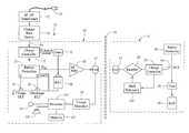
- FIG. 4is a block diagram of the internal components of one embodiment of an external charger and implantable pulse generator used in the SCS system of FIG. 1 ;
- FIG. 5is an example of a charge rate histogram generated by the external charger of FIG. 4 .
- the present inventionmay be used with an implantable pulse generator (IPG) or similar electrical stimulator, which may be used as a component of numerous different types of stimulation systems.
- IPGimplantable pulse generator
- SCSspinal cord stimulation
- the inventionlends itself well to applications in SCS, the invention, in its broadest aspects, may not be so limited. Rather, the invention may be used with any type of implantable electrical circuitry used to stimulate tissue.
- the present inventionmay be used as part of a pacemaker, a defibrillator, a cochlear stimulator, a retinal stimulator, a stimulator configured to produce coordinated limb movement, a cortical and deep brain stimulator, peripheral nerve stimulator, or in any other neural stimulator configured to treat urinary incontinence, sleep apnea, shoulder sublaxation, etc.
- an exemplary SCS system 10generally an implantable neurostimulation lead 12 , an implantable pulse generator (IPG) 14 , an external (non-implanted) programmer 16 , and an external (non-implanted) charger 18 .
- the lead 12is a percutaneous lead and, to that end, includes a plurality of in-line electrodes 20 carried on a flexible body 22 .
- the lead 12may take the form of a paddle lead.
- the IPG 14is electrically coupled to the lead 12 in order to direct electrical stimulation energy to each of the electrodes 20 .
- the IPG 14includes an outer case formed from an electrically conductive, biocompatible material, such as titanium and, in some instances, will function as an electrode.
- the caseforms a hermetically sealed compartment wherein the electronic and other components are protected from the body tissue and fluids.
- the electronic components of the IPG 14with the exception of the components needed to facilitate the recharging function (described below), will not be described herein. Details of the IPG 14 , including the battery, antenna coil, and telemetry and charging circuitry, are disclosed in U.S. Pat. No. 6,516,227, which is expressly incorporated herein by reference.
- the neurostimulation lead 12is implanted within the epidural space 26 of a patient through the use of a percutaneous needle or other convention technique, so as to be in close proximity to the spinal cord 28 .
- the electrodes 20may be used to supply stimulation energy to the spinal cord 28 or nerve roots.
- the preferred placement of the lead 12is such, that the electrodes 20 are adjacent, i.e., resting upon, the nerve area to be stimulated.
- the IPG 14is generally implanted in a surgically-made pocket either in the abdomen or above the buttocks.
- the IPG 14may, of course, also be implanted in other locations of the patient's body.
- a lead extension 30may facilitate locating the IPG 14 away from the exit point of the lead 12 .
- the IPG 14is programmed, or controlled, through the use of the external programmer 18 .
- the external programmer 18is transcutaneously coupled to the IPG 14 through a suitable communications link (represented by the arrow 32 ) that passes through the patient's skin 34 .
- Suitable linksinclude, but are not limited to radio frequency (RF) links, inductive links, optical links, and magnetic links.
- RFradio frequency
- the electronic components of the external programmer 18will not be described herein. Details of the external programmer, including the control circuitry, processing circuitry, and telemetry circuitry, are disclosed in U.S. Pat. No. 6,516,227, which has been previously incorporated herein by reference.
- the external charger 18is transcutaneously coupled to the IPG 14 through a suitable link (represented by the arrow 36 ) that passes through the patient's skin 34 , thereby coupling power into the IPG 14 for the purpose of operating the IPG 14 or replenishing a power source, such as a rechargeable battery (e.g., a Lithium Ion battery), within the IPG 14 .
- a power sourcesuch as a rechargeable battery (e.g., a Lithium Ion battery)
- the link 36is an inductive link; that is, energy from the external charger 18 is coupled to the battery within the IPG 14 via electromagnetic coupling.
- the external charger 18generates an audible tone when misaligned with the IPG 14 to alert the user to adjust the positioning of the external charger 18 relative to the IPG 14 .
- the external charger 18is designed to charge the battery of the IPG 14 to 80% capacity in two hours, and to 100% in three hours, at implant depths of up to 2.5 cm.
- the external charger 18When charging is complete, the external charger 18 generates an audible tone to alert the user to decouple the external charger 18 from the IPG 14 .
- the IPG 14may function as programmed without the external programmer 16 being present. While the external programmer 16 and external charger 18 are described herein as two separate and distinct units, it should be appreciated that the functionality of the external programmer 16 and external charger 18 can be combined into a single unit. It should be noted that rather than an IPG, the SCS system 10 may alternatively utilize an implantable receiver-stimulator (not shown) connected to leads 12 , 14 .
- the power sourcee.g., a battery
- the power sourcefor powering the implanted receiver, as well as control circuitry to command the receiver-stimulator, will be contained in an external controller/charger inductively coupled to the receiver-stimulator via an electromagnetic link.
- the external charger 18takes the form of a two-part system comprising a portable charger 50 and a charging base station 52 .
- the charging base station 52includes an AC plug 54 , so that it can be easily plugged into any standard 110 volt alternating current (VAC) or 200 VAC outlet.
- the charging base station 52further includes an AC/DC transformer 55 , which provides a suitable DC voltage (e.g., 5 VDC) to the circuitry within the charging base station 52 .
- the portable charger 50includes a housing 56 for containing circuitry, and in particular, the recharging circuitry and battery (not shown in FIG. 3 ), which will be discussed in further detail below.
- the housing 56is shaped and designed in a manner that allows the portable charger 50 to be detachably inserted into the charging base station 52 , thereby allowing the portable charger 50 , itself, to be recharged. Thus, both the IPG 14 and the portable charger 50 are rechargeable.
- the portable charger 50may be returned to the charging base station 52 between uses.
- the portable charger 50includes a charging head 58 connected to the housing 56 by way of a suitable flexible cable 60 .
- the charging head 58houses the AC coil (not shown in FIG. 3 ) from which the charging energy is transmitted.
- the portable charger 50further includes a disposable adhesive pouch 62 or Velcro® strip or patch, which may be placed on the patient's skin over the location where the IPG 14 is implanted.
- the charging head 58may be simply slid into the pouch 62 , or fastened to the strip or patch, so that it can be located in proximity to the IPG 14 (e.g., 2-3 cm).
- the portable charger 50does not include a separate charging head, but instead includes a single housing that contains the recharging circuitry, battery, and AC coil.
- the portable charger 50includes a bar charge indicator 64 located on the housing 56 , which provides a visual indication of the strength of the charging between the charging head 58 and IPG 14 in the form of bars.
- the portable charger 50comprises a misalignment indicator in the form of an audio transducer that provides an audible indication when the charging head 58 is misaligned relative to the IPG 14 .
- both the bar charge indicator 64 and misalignment indicatorcan be considered as charge strength indicators.
- the housing 56may simply be taped in place on the patient's skin using removable medical tape. Typically, charging of the IPG 14 continues until the battery of the IPG 14 has been charged to at least 80% of capacity.
- FIG. 4the recharging elements of the IPG 14 and portable charger 50 will now be described. It should be noted that the diagram of FIG. 4 is functional only, and is not intended to be limiting. Those of skill in the art, given the descriptions presented herein, should be able to readily fashion numerous types of recharging circuits, or equivalent circuits, that carry out the functions indicated and described.
- the portable charger 50includes a battery 66 , which in the illustrated embodiment is a rechargeable battery, such as a Lithium Ion battery.
- a rechargeable batterysuch as a Lithium Ion battery.
- energyshown by arrow 68
- the battery 66is fully charged in approximately four hours. Once the battery 66 is fully charged, it has enough energy to fully recharge the battery of the IPG 14 . If the portable charger 50 is not used and left on charger base station 52 , the battery 66 will self-discharge at a rate of about 10% per month. Alternatively, the battery 66 may be a replaceable battery.
- the portable charger 50includes a charge controller 70 , which serves to convert the DC power from the AC/DC transformer 55 to the proper charge current and voltage for the battery 66 , a battery protection circuit 72 , which monitors the voltage and current of the battery 66 to ensure safe operation via operation of FET switches 74 , 76 , and a fuse 78 that disconnects the battery 66 in response to an excessive current condition that occurs over an extended period of time. Further details discussing this control and protection circuitry are described in U.S. Pat. No. 6,516,227, which has been previously incorporated herein by reference.
- the portable charger 50further includes a power amplifier 80 , and in particular a radio frequency (RF) amplifier, for converting the DC power from the battery 66 to a large alternating current.
- the power amplifiermay take the form of an E-class amplifier.
- the portable charger 50further includes an antenna 82 , and in particular a coil, configured for transmitting the alternating current to the IPG 14 via inductive coupling.
- the coil 82may comprise a 36 turn, single layer, 30 AWG copper air-core coil having a typical inductance of 45 ⁇ H and a DC resistance of about 1.15 ⁇ .
- the coil 82may be tuned for a resonance at 80 KHz with a parallel capacitor (not shown).
- the IPG 14includes an antenna 84 , and in particular a coil, configured for receiving the alternating current from the portable charger 50 via the inductive coupling.
- the coil 84may be identical to, and preferably has the same resonant frequency as, the coil 82 of the portable charger 50 .
- the IPG 14further comprises rectifier circuitry 86 for converting the alternating current back to DC power.
- the rectifier circuitry 86may, e.g., take the form of a bridge rectifier circuit.
- the IPG 14further includes a rechargeable battery 88 , such as a Lithium Ion battery, which is charged by the DC power output by the rectifier circuitry 86 . In the illustrated embodiment, the battery 88 can be fully charged by the portable charger 50 in under three hours (80% charge in two hours).
- the portable charger 50includes a charge controller 90 , which serves to convert the DC power from the rectifier circuitry 86 to the proper charge current and voltage for the battery 88 , a battery protection circuit 92 , which monitors the voltage and current of the battery 88 to ensure safe operation via operation of a FET switch 94 , and a fuse 96 that disconnects the battery 88 in response to an excessive current condition that occurs over an extended period of time. Further details discussing this control and protection circuitry are described in U.S. Pat. No. 6,516,227, which has been previously incorporated herein by reference.
- the portable charger 50is capable of indicating when the battery 88 of the IPG 14 is fully charged or almost fully charged, and when the portable charger 50 is aligned/misaligned with the IPG 14 .
- the portable charger 50comprises charge detection circuitry 98 for detecting an electrical parameter indicative of the charge rate of the IPG 14 , and a processor 100 for determining the charging qualities of the IPG 14 , and in particular, when the IPG 14 is fully charged and when the portable charger 50 is aligned/misaligned with the IPG 14 , based on the detected electrical parameter.
- the portable charger 50further comprises memory 102 for storing an electrical parameter threshold value that the processor 100 uses to determine misalignment between the portable charger 50 and IPG 14 .
- the memory 102also store a computer program used by the processor 100 to perform the functions described below.
- the portable charger 50also includes an indicator 104 in the form of an audio transducer (speaker), which signals the user with an audible tone when the battery 88 of the IPG 14 is fully charged and when the portable charger 50 is misaligned with the IPG 14 .
- an indicator 104in the form of an audio transducer (speaker), which signals the user with an audible tone when the battery 88 of the IPG 14 is fully charged and when the portable charger 50 is misaligned with the IPG 14 .
- separate indicatorscan be used to indicate a full charge state and a misalignment condition.
- the electrical parameter sensed by the charge detection circuitry 98is a steady-state voltage having a value V 1 at the coil 82 , which is indicative of the charge rate of the IPG 14 . That is, the voltage value V 1 (which is dictated by the reflected impedance from the coil 84 of the IPG 14 ) is inversely proportional to the coupling between the coils 82 , 84 of the respective portable charger 50 and IPG 14 , and thus, the charge rate of the IPG 14 .
- the charge rateincreases.
- the charge detection circuitry 98also senses the voltage value V 1 at the coil 82 to detect when the IPG 14 has been fully charged.
- the IPG 14includes a back telemetry circuit 104 , which detects charge completion of the battery 88 and modulates the secondary load of the IPG 14 by changing the rectifier circuitry 86 from a full-wave rectifier into a half-wave rectifier/voltage clamp. This modulation, in turn, suddenly increases the reflected impedance into the coil 82 of the portable charger 50 , which suddenly increases the voltage value V 1 (e.g., a transient or pulsed component appears in the detected steady-state voltage) detected by the charge detection circuitry 98 .
- V 1e.g., a transient or pulsed component appears in the detected steady-state voltage
- the processor 100receives the voltage value V 1 from the charge detection circuitry 98 , and based on this value, operates the bar charge indicator 64 and audio transducer 104 accordingly. In particular, if the voltage value V 1 spikes or suddenly increases, the processor 100 determines that the battery 88 of the IPG 14 is fully charged, and prompts the audio transducer 104 (e.g., by sending a signal) to generate an audible tone or series of audible tones (e.g., an ON-OFF beeping sound), thereby alerting the user that the IPG 14 is fully charged.
- an audible tone or series of audible tonese.g., an ON-OFF beeping sound
- the processor 100operates the bar charge indicator 64 to display the proper number of bars in accordance with the charge rate indicated by the voltage value V 1 .
- the processor 100also compares the voltage value V 1 to the electrical parameter threshold value (in this case, a voltage threshold value) stored in the memory 102 to determine misalignment between the portable charger 50 and IPG 14 .
- the processor 100compares the voltage value V 1 with the voltage threshold value stored in the memory 102 to determine whether a misalignment condition has occurred, and operates the audio transducer 104 in a binary fashion, meaning that it only indicates if a particular condition has been satisfied or not satisfied (i.e., misaligned or not misaligned).
- the voltage threshold value stored in the memory 102can be varied in order to modify the actual charge rate at which a misalignment condition is deemed to occur.
- the voltage threshold valuecan be increased, so that the audible misalignment tone does not sound when the charge rate is optimum or otherwise suitable for that implant depth.
- the voltage threshold valuecan be decreased, so that the audible misalignment tone sounds when the charge rate is not optimum or otherwise suitable for that implant depth.
- the audible misalignment tonewill only sound when the charge rate is sub-optimal for the specific implant depth or orientation.
- Adjustment of the voltage threshold valuecan be accomplished in any one of a variety of manners.
- the memory 102can simply be manually programmed by a clinician with a voltage threshold value suitable for the implant depth. That is, if the IPG 14 has been implanted within the patient relatively deep, the clinician will program the memory 102 with a relatively high voltage threshold value, and if the IPG 14 has been implanted within the patient relatively shallow, the clinician will program the memory 102 with a relatively low voltage threshold value.
- the portable charger 50can be positioned relative to the IPG 14 until the bar charge indicator 64 indicates a maximum charge rate, at which time the processor 100 (as prompted by the user, e.g., by actuating a button (not shown)) can modify the voltage threshold value to the voltage value V 1 , which is indicative of the maximum charge rate.
- the portable charger 50can be trained over a series of discrete time periods during, e.g., a single session or over multiple sessions.
- the IPG 14may be charged by the portable charger 50 over the time periods, during which time the processor 100 can continually determine the maximum voltage value V 1 , which is indicative of the maximum charge rate, and automatically modify the voltage threshold value to the maximum voltage value V 1 .
- the voltage threshold valuecan be modified to a voltage value just below the maximum voltage value V 1 , thereby allowing for suitable charge rates less than optimal.
- Yet another embodimenttrades off the ease of positioning the portable charger 50 with the degree of charge rate optimization that the misalignment tone will sound.
- This embodimentconsiders not only the maximum charge rate or estimate thereof, but also the histogram of the charge rates across difference charger positions, such that an acceptable zone for locating the portable charger 50 could be maintained automatically.
- the processor 100Based on the voltage values V 1 detected by the charge detection circuitry 98 over a series of time periods, the processor 100 generates a histogram of voltage values V 1 , and modifies the voltage threshold value stored in the memory 102 equal to the value of the most common voltage V 1 , which is indicative of the most common rate used to charge the IPG 14 . For example, FIG.
- the processor 100will modify the voltage threshold value to 7V, so that the threshold at which the misalignment tone sounds will be adjusted.
- the voltage threshold valuecan be modified to a voltage value just below the most common voltage value V 1 (e.g., 6V), thereby allowing for suitable charge rates less than the most common charge rate.
- the adjustable voltage threshold valuecan be used to modify the threshold at which a binary indicator generates a user-discernible signal other than a misalignment signal.
- the voltage threshold valuecan correspond to an audio transducer that sounds an alignment tone (i.e., an audible tone that alerts the patient that the portable charger 50 is aligned with the IPG 14 ), or an indicator that illuminates an alignment light (i.e., a visual signal that alerts the patient that the portable charger 50 is aligned with the IPG 14 ).
- one or more adjustable charge rate threshold valuescan be used to modify the threshold(s) at which non-binary indicators generate user-discernible signals.
- the charge rate threshold value(s)can correspond to a bar indicator, such as, e.g., the bar charge indicator 64 , such that the thresholds at which the number of bars increases or decreases can be adjusted.
- any electrical parameter indicative of the charge ratecan be used as an indication of the charge rate.
- the charge current of the battery 88 in the IPG 14is also indicative of the charge rate, with the charge current increasing as the charge rate increases and decreasing as the charge rate decreases.
- the value (or some indication) of the battery charge currentcan be modulated onto the reflected impedance via the back telemetry circuit 104 to provide an indication of the charge rate to the charger 50 .
- the value of the charge current in the modulated signalcan then be sensed by the charge detection circuitry 98 of the charger 50 as a modulated voltage, and then, used by the processor 100 to operate the bar charge indicator 64 and audio transducer 104 in the same manner described above.
- the charge current of the battery 88may not always be indicative of the actual charge rate. That is, the constant voltage phase causes the battery charge current to decrease, regardless of the optimal alignment and spacing between the coils 82 , 84 . Thus, the battery charge current may decrease even in the presence of a maximum charge rate at the end of the charging cycle.
- the processor 100 in the charger 50may normalize the threshold adjustment method or the back telemetry circuit 104 in the IPG 104 may normalize the information modulated onto the reflected impedance to the lower battery charge current during the constant voltage phase.
- the illustrated embodimenthas been described as performing the charge rate indication and processing functions in the portable charger 50 , it should be appreciated that any of these functions can be performed in the charger base station 52 , or even the IPG 14 . If the indication function is performed by the IPG 14 , the user-discernible signal can take the form of a vibration or a modulated electrical stimulation.
Landscapes
- Health & Medical Sciences (AREA)
- Engineering & Computer Science (AREA)
- Biomedical Technology (AREA)
- Nuclear Medicine, Radiotherapy & Molecular Imaging (AREA)
- Radiology & Medical Imaging (AREA)
- Life Sciences & Earth Sciences (AREA)
- Animal Behavior & Ethology (AREA)
- General Health & Medical Sciences (AREA)
- Public Health (AREA)
- Veterinary Medicine (AREA)
- Electrotherapy Devices (AREA)
- Charge And Discharge Circuits For Batteries Or The Like (AREA)
- Secondary Cells (AREA)
Abstract
Description
Claims (42)
Priority Applications (11)
| Application Number | Priority Date | Filing Date | Title |
|---|---|---|---|
| US11/748,436US7932696B2 (en) | 2007-05-14 | 2007-05-14 | Charger alignment indicator with adjustable threshold |
| JP2010508404AJP5646991B2 (en) | 2007-05-14 | 2008-05-14 | Alignment indicator for smart charger |
| CA2826117ACA2826117C (en) | 2007-05-14 | 2008-05-14 | Smart charger alignment indicator |
| PCT/US2008/006129WO2008143857A1 (en) | 2007-05-14 | 2008-05-14 | Smart charger alignment indicator |
| ES12167016.0TES2459597T3 (en) | 2007-05-14 | 2008-05-14 | Intelligent charger alignment indicator |
| EP12167016.0AEP2495015B1 (en) | 2007-05-14 | 2008-05-14 | Smart charger alignment indicator |
| EP08767685.4AEP2148724B1 (en) | 2007-05-14 | 2008-05-14 | Smart charger alignment indicator |
| CA2684995ACA2684995C (en) | 2007-05-14 | 2008-05-14 | Smart charger alignment indicator |
| US13/053,998US8044635B2 (en) | 2007-05-14 | 2011-03-22 | Charger alignment indicator with adjustable threshold |
| US13/247,642US8598841B2 (en) | 2007-05-14 | 2011-09-28 | Charger alignment indicator with adjustable threshold |
| JP2013228682AJP5701363B2 (en) | 2007-05-14 | 2013-11-01 | Alignment indicator for smart charger |
Applications Claiming Priority (1)
| Application Number | Priority Date | Filing Date | Title |
|---|---|---|---|
| US11/748,436US7932696B2 (en) | 2007-05-14 | 2007-05-14 | Charger alignment indicator with adjustable threshold |
Related Child Applications (1)
| Application Number | Title | Priority Date | Filing Date |
|---|---|---|---|
| US13/053,998ContinuationUS8044635B2 (en) | 2007-05-14 | 2011-03-22 | Charger alignment indicator with adjustable threshold |
Publications (2)
| Publication Number | Publication Date |
|---|---|
| US20080288025A1 US20080288025A1 (en) | 2008-11-20 |
| US7932696B2true US7932696B2 (en) | 2011-04-26 |
Family
ID=39627848
Family Applications (3)
| Application Number | Title | Priority Date | Filing Date |
|---|---|---|---|
| US11/748,436Active2028-05-21US7932696B2 (en) | 2007-05-14 | 2007-05-14 | Charger alignment indicator with adjustable threshold |
| US13/053,998ActiveUS8044635B2 (en) | 2007-05-14 | 2011-03-22 | Charger alignment indicator with adjustable threshold |
| US13/247,642Active2027-10-09US8598841B2 (en) | 2007-05-14 | 2011-09-28 | Charger alignment indicator with adjustable threshold |
Family Applications After (2)
| Application Number | Title | Priority Date | Filing Date |
|---|---|---|---|
| US13/053,998ActiveUS8044635B2 (en) | 2007-05-14 | 2011-03-22 | Charger alignment indicator with adjustable threshold |
| US13/247,642Active2027-10-09US8598841B2 (en) | 2007-05-14 | 2011-09-28 | Charger alignment indicator with adjustable threshold |
Country Status (6)
| Country | Link |
|---|---|
| US (3) | US7932696B2 (en) |
| EP (2) | EP2148724B1 (en) |
| JP (2) | JP5646991B2 (en) |
| CA (2) | CA2684995C (en) |
| ES (1) | ES2459597T3 (en) |
| WO (1) | WO2008143857A1 (en) |
Cited By (64)
| Publication number | Priority date | Publication date | Assignee | Title |
|---|---|---|---|---|
| US8594806B2 (en) | 2010-04-30 | 2013-11-26 | Cyberonics, Inc. | Recharging and communication lead for an implantable device |
| US9031666B2 (en) | 2011-07-19 | 2015-05-12 | Greatbatch Ltd. | Devices and methods for visually indicating the alignment of a transcutaneous energy transfer device over an implanted medical device |
| US9044614B2 (en) | 2013-03-15 | 2015-06-02 | Alfred E. Mann Foundation For Scientific Research | High voltage monitoring successive approximation analog to digital converter |
| US9155901B2 (en) | 2013-07-29 | 2015-10-13 | Alfred E. Mann Foundation For Scientific Research | Implant charging field control through radio link |
| US9166441B2 (en) | 2013-07-29 | 2015-10-20 | Alfred E. Mann Foundation For Scientific Research | Microprocessor controlled class E driver |
| US9205273B2 (en) | 2013-07-29 | 2015-12-08 | Alfred E. Mann Foundation For Scientific Research | High efficiency magnetic link for implantable devices |
| US9221119B2 (en) | 2013-05-03 | 2015-12-29 | Alfred E. Mann Foundation For Scientific Research | High reliability wire welding for implantable devices |
| US9287040B2 (en) | 2012-07-27 | 2016-03-15 | Thoratec Corporation | Self-tuning resonant power transfer systems |
| US9308378B2 (en) | 2013-05-03 | 2016-04-12 | Alfred E. Mann Foundation For Scientific Research | Implant recharger handshaking system and method |
| US9343923B2 (en) | 2012-08-23 | 2016-05-17 | Cyberonics, Inc. | Implantable medical device with backscatter signal based communication |
| US9427574B2 (en) | 2014-08-15 | 2016-08-30 | Axonics Modulation Technologies, Inc. | Implantable lead affixation structure for nerve stimulation to alleviate bladder dysfunction and other indication |
| US9433779B2 (en) | 2013-05-03 | 2016-09-06 | Alfred E. Mann Foundation For Scientific Research | Multi-branch stimulation electrode for subcutaneous field stimulation |
| US9446241B2 (en) | 2013-03-15 | 2016-09-20 | Alfred E. Mann Foundation For Scientific Research | Current sensing multiple output current stimulators |
| US9517338B1 (en) | 2016-01-19 | 2016-12-13 | Axonics Modulation Technologies, Inc. | Multichannel clip device and methods of use |
| US9533155B2 (en) | 2014-08-15 | 2017-01-03 | Axonics Modulation Technologies, Inc. | Methods for determining neurostimulation electrode configurations based on neural localization |
| US9555246B2 (en) | 2014-08-15 | 2017-01-31 | Axonics Modulation Technologies, Inc. | Electromyographic lead positioning and stimulation titration in a nerve stimulation system for treatment of overactive bladder |
| US9583874B2 (en) | 2014-10-06 | 2017-02-28 | Thoratec Corporation | Multiaxial connector for implantable devices |
| US9592397B2 (en) | 2012-07-27 | 2017-03-14 | Thoratec Corporation | Thermal management for implantable wireless power transfer systems |
| US9680310B2 (en) | 2013-03-15 | 2017-06-13 | Thoratec Corporation | Integrated implantable TETS housing including fins and coil loops |
| US9700731B2 (en) | 2014-08-15 | 2017-07-11 | Axonics Modulation Technologies, Inc. | Antenna and methods of use for an implantable nerve stimulator |
| US9728981B2 (en) | 2012-08-31 | 2017-08-08 | Alfred E. Mann Foundation For Scientific Research | Feedback controlled coil driver for inductive power transfer |
| US9805863B2 (en) | 2012-07-27 | 2017-10-31 | Thoratec Corporation | Magnetic power transmission utilizing phased transmitter coil arrays and phased receiver coil arrays |
| US9802051B2 (en) | 2014-08-15 | 2017-10-31 | Axonics Modulation Technologies, Inc. | External pulse generator device and associated methods for trial nerve stimulation |
| US9825471B2 (en) | 2012-07-27 | 2017-11-21 | Thoratec Corporation | Resonant power transfer systems with protective algorithm |
| US9855437B2 (en) | 2013-11-11 | 2018-01-02 | Tc1 Llc | Hinged resonant power transfer coil |
| US9895546B2 (en) | 2015-01-09 | 2018-02-20 | Axonics Modulation Technologies, Inc. | Patient remote and associated methods of use with a nerve stimulation system |
| US9925381B2 (en) | 2015-07-10 | 2018-03-27 | Axonics Modulation Technologies, Inc. | Implantable nerve stimulator having internal electronics without ASIC and methods of use |
| US9935498B2 (en) | 2012-09-25 | 2018-04-03 | Cyberonics, Inc. | Communication efficiency with an implantable medical device using a circulator and a backscatter signal |
| US20180262037A1 (en)* | 2017-03-09 | 2018-09-13 | Werner Meskens | Multi-loop implant charger |
| WO2018175005A1 (en) | 2017-03-21 | 2018-09-27 | Boston Scientific Neuromodulation Corporation | External charger with three-axis magnetic field sensor to determine implantable medical device position |
| US10092762B2 (en) | 2014-08-15 | 2018-10-09 | Axonics Modulation Technologies, Inc. | Integrated electromyographic clinician programmer for use with an implantable neurostimulator |
| US10148126B2 (en) | 2015-08-31 | 2018-12-04 | Tc1 Llc | Wireless energy transfer system and wearables |
| US10177604B2 (en) | 2015-10-07 | 2019-01-08 | Tc1 Llc | Resonant power transfer systems having efficiency optimization based on receiver impedance |
| US10186760B2 (en) | 2014-09-22 | 2019-01-22 | Tc1 Llc | Antenna designs for communication between a wirelessly powered implant to an external device outside the body |
| US10195423B2 (en) | 2016-01-19 | 2019-02-05 | Axonics Modulation Technologies, Inc. | Multichannel clip device and methods of use |
| US10226637B2 (en) | 2016-06-15 | 2019-03-12 | Boston Scientific Neuromodulation Corporation | External charger for an implantable medical device having alignment and centering capabilities |
| US10251987B2 (en) | 2012-07-27 | 2019-04-09 | Tc1 Llc | Resonant power transmission coils and systems |
| US10291067B2 (en) | 2012-07-27 | 2019-05-14 | Tc1 Llc | Computer modeling for resonant power transfer systems |
| US10342984B2 (en) | 2016-06-15 | 2019-07-09 | Boston Scientific Neuromodulation Corporation | Split coil for uniform magnetic field generation from an external charger for an implantable medical device |
| US10363426B2 (en) | 2016-06-15 | 2019-07-30 | Boston Scientific Neuromodulation Corporation | External charger for an implantable medical device for determining position using phase angle or a plurality of parameters as determined from at least one sense coil |
| US10373756B2 (en) | 2013-03-15 | 2019-08-06 | Tc1 Llc | Malleable TETs coil with improved anatomical fit |
| US10376704B2 (en) | 2016-02-12 | 2019-08-13 | Axonics Modulation Technologies, Inc. | External pulse generator device and associated methods for trial nerve stimulation |
| US10383990B2 (en) | 2012-07-27 | 2019-08-20 | Tc1 Llc | Variable capacitor for resonant power transfer systems |
| US10525181B2 (en) | 2012-07-27 | 2020-01-07 | Tc1 Llc | Resonant power transfer system and method of estimating system state |
| US10561835B2 (en) | 2006-10-31 | 2020-02-18 | Medtronic, Inc. | Implantable medical lead with threaded fixation |
| US10603500B2 (en) | 2016-01-29 | 2020-03-31 | Axonics Modulation Technologies, Inc. | Methods and systems for frequency adjustment to optimize charging of implantable neurostimulator |
| US10603501B2 (en) | 2016-06-15 | 2020-03-31 | Boston Scientific Neuromodulation Corporation | External charger for an implantable medical device having at least one sense coil concentric with a charging coil for determining position |
| US10615642B2 (en) | 2013-11-11 | 2020-04-07 | Tc1 Llc | Resonant power transfer systems with communications |
| US10610692B2 (en) | 2014-03-06 | 2020-04-07 | Tc1 Llc | Electrical connectors for implantable devices |
| US10682521B2 (en) | 2014-08-15 | 2020-06-16 | Axonics Modulation Technologies, Inc. | Attachment devices and associated methods of use with a nerve stimulation charging device |
| US10695476B2 (en) | 2013-11-11 | 2020-06-30 | Tc1 Llc | Resonant power transfer systems with communications |
| US10770923B2 (en) | 2018-01-04 | 2020-09-08 | Tc1 Llc | Systems and methods for elastic wireless power transmission devices |
| US10898292B2 (en) | 2016-09-21 | 2021-01-26 | Tc1 Llc | Systems and methods for locating implanted wireless power transmission devices |
| US11110283B2 (en) | 2018-02-22 | 2021-09-07 | Axonics, Inc. | Neurostimulation leads for trial nerve stimulation and methods of use |
| US11129996B2 (en) | 2016-06-15 | 2021-09-28 | Boston Scientific Neuromodulation Corporation | External charger for an implantable medical device for determining position and optimizing power transmission using resonant frequency as determined from at least one sense coil |
| US11197990B2 (en) | 2017-01-18 | 2021-12-14 | Tc1 Llc | Systems and methods for transcutaneous power transfer using microneedles |
| US20220203103A1 (en)* | 2020-12-28 | 2022-06-30 | Advanced Neuromodulation Systems Inc. | System and method for alignment of a wireless charger to an implantable medical device |
| US11439829B2 (en) | 2019-05-24 | 2022-09-13 | Axonics, Inc. | Clinician programmer methods and systems for maintaining target operating temperatures |
| US11471692B2 (en) | 2016-06-15 | 2022-10-18 | Boston Scientific Neuromodulation Corporation | External charger for an implantable medical device for adjusting charging power based on determined position using at least one sense coil |
| US11484723B2 (en) | 2015-01-09 | 2022-11-01 | Axonics, Inc. | Attachment devices and associated methods of use with a nerve stimulation charging device |
| US11642537B2 (en) | 2019-03-11 | 2023-05-09 | Axonics, Inc. | Charging device with off-center coil |
| US11848090B2 (en) | 2019-05-24 | 2023-12-19 | Axonics, Inc. | Trainer for a neurostimulator programmer and associated methods of use with a neurostimulation system |
| US12376787B2 (en) | 2020-07-21 | 2025-08-05 | DePuy Synthes Products, Inc. | Bone fixation monitoring system |
| US12420103B1 (en) | 2020-08-20 | 2025-09-23 | Axonics, Inc. | Neurostimulation leads with reduced current leakage |
Families Citing this family (39)
| Publication number | Priority date | Publication date | Assignee | Title |
|---|---|---|---|---|
| WO2007098200A2 (en) | 2006-02-16 | 2007-08-30 | Imthera Medical, Inc. | An rfid-based apparatus, system, and method for therapeutic treatment of obstructive sleep apnea |
| US7932696B2 (en)* | 2007-05-14 | 2011-04-26 | Boston Scientific Neuromodulation Corporation | Charger alignment indicator with adjustable threshold |
| EP2197536A1 (en) | 2007-10-09 | 2010-06-23 | Imthera Medical, Inc. | System and method for neural stimulation |
| EP2153866A1 (en)* | 2008-08-14 | 2010-02-17 | Oncotherm Kft. | Portable radiofrequency hyperthermia device with flexible treatment electrode for electric field capacitive coupled energy transfer |
| EP2349139B1 (en) | 2008-10-09 | 2017-05-31 | Imthera Medical, Inc. | Stimulation of a hypoglossal nerve for controlling the position of a patient's tongue |
| EP2349079B1 (en)* | 2008-10-10 | 2023-06-07 | Implantica Patent Ltd. | Charger for implant |
| US9227075B2 (en) | 2008-12-03 | 2016-01-05 | Boston Scientific Neuromodulation Corporation | External charger with adjustable alignment indicator |
| US20100262029A1 (en)* | 2009-04-14 | 2010-10-14 | Kelly N Patrick | Needle implantable atrial fibrillation monitor and methods for use therewith |
| US20100305663A1 (en)* | 2009-06-02 | 2010-12-02 | Boston Scientific Neuromodulation Corporation | Implantable medical device system having short range communication link between an external controller and an external charger |
| US20100331918A1 (en)* | 2009-06-30 | 2010-12-30 | Boston Scientific Neuromodulation Corporation | Moldable charger with curable material for charging an implantable pulse generator |
| US20100331919A1 (en)* | 2009-06-30 | 2010-12-30 | Boston Scientific Neuromodulation Corporation | Moldable charger having hinged sections for charging an implantable pulse generator |
| US8260432B2 (en)* | 2009-06-30 | 2012-09-04 | Boston Scientific Neuromodulation Corporation | Moldable charger with shape-sensing means for an implantable pulse generator |
| US9399131B2 (en)* | 2009-06-30 | 2016-07-26 | Boston Scientific Neuromodulation Corporation | Moldable charger with support members for charging an implantable pulse generator |
| JP5434330B2 (en)* | 2009-07-22 | 2014-03-05 | ソニー株式会社 | Power receiving device, power transmission system, charging device, and power transmission method |
| WO2011059531A1 (en) | 2009-11-10 | 2011-05-19 | Imthera Medical, Inc. | System for stimulating a hypoglossal nerve for controlling the position of a patient's tongue |
| JP5427068B2 (en)* | 2010-02-26 | 2014-02-26 | テルモ株式会社 | Electrical stimulator |
| US10389156B2 (en) | 2010-05-21 | 2019-08-20 | Qnovo Inc. | Method and circuitry to adaptively charge a battery/cell |
| US9142994B2 (en) | 2012-09-25 | 2015-09-22 | Qnovo, Inc. | Method and circuitry to adaptively charge a battery/cell |
| US11397215B2 (en) | 2010-05-21 | 2022-07-26 | Qnovo Inc. | Battery adaptive charging using battery physical phenomena |
| US11791647B2 (en) | 2010-05-21 | 2023-10-17 | Qnovo Inc. | Method and circuitry to adaptively charge a battery/cell |
| US12081057B2 (en) | 2010-05-21 | 2024-09-03 | Qnovo Inc. | Method and circuitry to adaptively charge a battery/cell |
| US11397216B2 (en) | 2010-05-21 | 2022-07-26 | Qnovo Inc. | Battery adaptive charging using a battery model |
| US9692248B2 (en) | 2013-03-14 | 2017-06-27 | Blackberry Limited | Positioning aid for wireless energy transfer |
| US9878170B2 (en) | 2013-03-15 | 2018-01-30 | Globus Medical, Inc. | Spinal cord stimulator system |
| US9872997B2 (en) | 2013-03-15 | 2018-01-23 | Globus Medical, Inc. | Spinal cord stimulator system |
| US9440076B2 (en) | 2013-03-15 | 2016-09-13 | Globus Medical, Inc. | Spinal cord stimulator system |
| US9887574B2 (en) | 2013-03-15 | 2018-02-06 | Globus Medical, Inc. | Spinal cord stimulator system |
| US9461492B1 (en) | 2013-04-19 | 2016-10-04 | Qnovo Inc. | Method and circuitry to adaptively charge a battery/cell using a charge-time parameter |
| US10574079B1 (en)* | 2014-06-20 | 2020-02-25 | Qnovo Inc. | Wireless charging techniques and circuitry for a battery |
| US11760221B2 (en)* | 2017-06-27 | 2023-09-19 | A9.Com, Inc. | Charging systems and methods for autonomous carts |
| TWI667860B (en)* | 2018-02-09 | 2019-08-01 | 鉅旺生技股份有限公司 | Long-range wireless charging enhancement structure for implantable medical devices |
| DE102018206754A1 (en)* | 2018-05-02 | 2019-11-07 | Kardion Gmbh | Method and device for determining the temperature at a surface and use of the method |
| DE102018206731A1 (en) | 2018-05-02 | 2019-11-07 | Kardion Gmbh | Device for inductive energy transmission in a human body and use of the device |
| DE102018206750A1 (en) | 2018-05-02 | 2019-11-07 | Kardion Gmbh | Device for inductive energy transfer into a human body and its use |
| DE102018208555A1 (en) | 2018-05-30 | 2019-12-05 | Kardion Gmbh | Apparatus for anchoring a cardiac assist system in a blood vessel, method of operation, and method of making a device and cardiac assist system |
| JP2021176250A (en)* | 2020-05-01 | 2021-11-04 | ダイワ通信株式会社 | Charging device |
| US20220026391A1 (en)* | 2020-07-24 | 2022-01-27 | Medtronic, Inc. | Estimating coil implant depth for wireless power transfer |
| US11699551B2 (en) | 2020-11-05 | 2023-07-11 | Kardion Gmbh | Device for inductive energy transmission in a human body and use of the device |
| WO2025172337A1 (en)* | 2024-02-16 | 2025-08-21 | Implantica Patent Ltd | Implantable medical device having a safety unit |
Citations (8)
| Publication number | Priority date | Publication date | Assignee | Title |
|---|---|---|---|---|
| US3646940A (en) | 1969-07-15 | 1972-03-07 | Univ Minnesota | Implantable electronic stimulator electrode and method |
| US3822708A (en) | 1972-12-07 | 1974-07-09 | Clinical Technology Corp | Electrical spinal cord stimulating device and method for management of pain |
| WO1998011942A1 (en) | 1996-09-17 | 1998-03-26 | Sulzer Intermedics Inc. | Enhanced transcutaneous recharging system for battery powered implantable medical device |
| US6194874B1 (en)* | 1999-03-17 | 2001-02-27 | Telefonaktiebolaget Lm Ericsson (Publ) | System and method for maintenance charging of battery cells |
| EP1136098A2 (en) | 2000-03-13 | 2001-09-26 | Pacesetter, Inc. | System and method of automatically adjusting auto capture safety margin |
| US6516227B1 (en) | 1999-07-27 | 2003-02-04 | Advanced Bionics Corporation | Rechargeable spinal cord stimulator system |
| US20050075699A1 (en) | 2003-10-02 | 2005-04-07 | Medtronic, Inc. | System and method for transcutaneous energy transfer achieving high efficiency |
| US20060247737A1 (en) | 2005-04-29 | 2006-11-02 | Medtronic, Inc. | Alignment indication for transcutaneous energy transfer |
Family Cites Families (6)
| Publication number | Priority date | Publication date | Assignee | Title |
|---|---|---|---|---|
| US5690693A (en) | 1995-06-07 | 1997-11-25 | Sulzer Intermedics Inc. | Transcutaneous energy transmission circuit for implantable medical device |
| JP2000111315A (en)* | 1998-09-30 | 2000-04-18 | Omron Corp | Photoelectric sensor and its production method |
| US6553263B1 (en)* | 1999-07-30 | 2003-04-22 | Advanced Bionics Corporation | Implantable pulse generators using rechargeable zero-volt technology lithium-ion batteries |
| US6594524B2 (en)* | 2000-12-12 | 2003-07-15 | The Trustees Of The University Of Pennsylvania | Adaptive method and apparatus for forecasting and controlling neurological disturbances under a multi-level control |
| US6892092B2 (en)* | 2001-10-29 | 2005-05-10 | Cardiac Pacemakers, Inc. | Cardiac rhythm management system with noise detector utilizing a hysteresis providing threshold |
| US7932696B2 (en)* | 2007-05-14 | 2011-04-26 | Boston Scientific Neuromodulation Corporation | Charger alignment indicator with adjustable threshold |
- 2007
- 2007-05-14USUS11/748,436patent/US7932696B2/enactiveActive
- 2008
- 2008-05-14WOPCT/US2008/006129patent/WO2008143857A1/enactiveApplication Filing
- 2008-05-14ESES12167016.0Tpatent/ES2459597T3/enactiveActive
- 2008-05-14EPEP08767685.4Apatent/EP2148724B1/enactiveActive
- 2008-05-14EPEP12167016.0Apatent/EP2495015B1/enactiveActive
- 2008-05-14CACA2684995Apatent/CA2684995C/enactiveActive
- 2008-05-14JPJP2010508404Apatent/JP5646991B2/enactiveActive
- 2008-05-14CACA2826117Apatent/CA2826117C/enactiveActive
- 2011
- 2011-03-22USUS13/053,998patent/US8044635B2/enactiveActive
- 2011-09-28USUS13/247,642patent/US8598841B2/enactiveActive
- 2013
- 2013-11-01JPJP2013228682Apatent/JP5701363B2/enactiveActive
Patent Citations (9)
| Publication number | Priority date | Publication date | Assignee | Title |
|---|---|---|---|---|
| US3646940A (en) | 1969-07-15 | 1972-03-07 | Univ Minnesota | Implantable electronic stimulator electrode and method |
| US3822708A (en) | 1972-12-07 | 1974-07-09 | Clinical Technology Corp | Electrical spinal cord stimulating device and method for management of pain |
| WO1998011942A1 (en) | 1996-09-17 | 1998-03-26 | Sulzer Intermedics Inc. | Enhanced transcutaneous recharging system for battery powered implantable medical device |
| US6194874B1 (en)* | 1999-03-17 | 2001-02-27 | Telefonaktiebolaget Lm Ericsson (Publ) | System and method for maintenance charging of battery cells |
| US6516227B1 (en) | 1999-07-27 | 2003-02-04 | Advanced Bionics Corporation | Rechargeable spinal cord stimulator system |
| EP1136098A2 (en) | 2000-03-13 | 2001-09-26 | Pacesetter, Inc. | System and method of automatically adjusting auto capture safety margin |
| EP1136098A3 (en) | 2000-03-13 | 2003-07-30 | Pacesetter, Inc. | System and method of automatically adjusting auto capture safety margin |
| US20050075699A1 (en) | 2003-10-02 | 2005-04-07 | Medtronic, Inc. | System and method for transcutaneous energy transfer achieving high efficiency |
| US20060247737A1 (en) | 2005-04-29 | 2006-11-02 | Medtronic, Inc. | Alignment indication for transcutaneous energy transfer |
Non-Patent Citations (5)
| Title |
|---|
| Office Action dated Apr. 27, 2010 in related European Patent Application No. 08767685.4-2305, Applicant: Boston Scientific Neuromodulation Corporation, (5 pages). |
| Office Action dated Oct. 1, 2010 in related European Patent Application No. 08767685.4-2305, Applicant: Boston Scientific Neuromodulation Corporation, (4 pages). |
| PCT International Preliminary Report on Patentability (Chapter I of the Patent Cooperation Treaty) for PCT/US2008/006129, Applicant: Boston Scientific Neuromodulation Corporation, Form PCT/IB/326 and 373, dated Nov. 26, 2009 (9pages). |
| PCT International Search Report for PCT/US2008/006129, Applicant: Boston Scientific Neuromodulation Corporation, Form PCT/ISA/210 and 220, dated Sep. 9, 2008 (6 pages). |
| PCT Written Opinion of the International Search Authority for PCT/US2008/006129, Applicant: Boston Scientific Neuromodulation Corporation, Form PCT/ISA/237, dated Sep. 9, 2008 (7 pages). |
Cited By (128)
| Publication number | Priority date | Publication date | Assignee | Title |
|---|---|---|---|---|
| US10561835B2 (en) | 2006-10-31 | 2020-02-18 | Medtronic, Inc. | Implantable medical lead with threaded fixation |
| US8594806B2 (en) | 2010-04-30 | 2013-11-26 | Cyberonics, Inc. | Recharging and communication lead for an implantable device |
| US9375567B2 (en) | 2011-07-19 | 2016-06-28 | Nuvectra Corporation | Devices and methods for visually indicating the alignment of a transcutaneous energy transfer device over an implanted medical device |
| US9031666B2 (en) | 2011-07-19 | 2015-05-12 | Greatbatch Ltd. | Devices and methods for visually indicating the alignment of a transcutaneous energy transfer device over an implanted medical device |
| US9997928B2 (en) | 2012-07-27 | 2018-06-12 | Tc1 Llc | Self-tuning resonant power transfer systems |
| US10383990B2 (en) | 2012-07-27 | 2019-08-20 | Tc1 Llc | Variable capacitor for resonant power transfer systems |
| US10525181B2 (en) | 2012-07-27 | 2020-01-07 | Tc1 Llc | Resonant power transfer system and method of estimating system state |
| US9287040B2 (en) | 2012-07-27 | 2016-03-15 | Thoratec Corporation | Self-tuning resonant power transfer systems |
| US10434235B2 (en) | 2012-07-27 | 2019-10-08 | Tci Llc | Thermal management for implantable wireless power transfer systems |
| US10637303B2 (en) | 2012-07-27 | 2020-04-28 | Tc1 Llc | Magnetic power transmission utilizing phased transmitter coil arrays and phased receiver coil arrays |
| US10693299B2 (en) | 2012-07-27 | 2020-06-23 | Tc1 Llc | Self-tuning resonant power transfer systems |
| US10668197B2 (en) | 2012-07-27 | 2020-06-02 | Tc1 Llc | Resonant power transmission coils and systems |
| US10251987B2 (en) | 2012-07-27 | 2019-04-09 | Tc1 Llc | Resonant power transmission coils and systems |
| US9592397B2 (en) | 2012-07-27 | 2017-03-14 | Thoratec Corporation | Thermal management for implantable wireless power transfer systems |
| US10291067B2 (en) | 2012-07-27 | 2019-05-14 | Tc1 Llc | Computer modeling for resonant power transfer systems |
| US9825471B2 (en) | 2012-07-27 | 2017-11-21 | Thoratec Corporation | Resonant power transfer systems with protective algorithm |
| US9805863B2 (en) | 2012-07-27 | 2017-10-31 | Thoratec Corporation | Magnetic power transmission utilizing phased transmitter coil arrays and phased receiver coil arrays |
| US10644514B2 (en) | 2012-07-27 | 2020-05-05 | Tc1 Llc | Resonant power transfer systems with protective algorithm |
| US9343923B2 (en) | 2012-08-23 | 2016-05-17 | Cyberonics, Inc. | Implantable medical device with backscatter signal based communication |
| US9728981B2 (en) | 2012-08-31 | 2017-08-08 | Alfred E. Mann Foundation For Scientific Research | Feedback controlled coil driver for inductive power transfer |
| US9935498B2 (en) | 2012-09-25 | 2018-04-03 | Cyberonics, Inc. | Communication efficiency with an implantable medical device using a circulator and a backscatter signal |
| US9981130B2 (en) | 2013-03-15 | 2018-05-29 | Alfred E. Mann Foundation For Scientific Research | Current sensing multiple output current stimulators |
| US10476317B2 (en) | 2013-03-15 | 2019-11-12 | Tci Llc | Integrated implantable TETs housing including fins and coil loops |
| US9680310B2 (en) | 2013-03-15 | 2017-06-13 | Thoratec Corporation | Integrated implantable TETS housing including fins and coil loops |
| US10603495B2 (en) | 2013-03-15 | 2020-03-31 | The Alfred E. Mann Foundation For Scientific Research | Current sensing multiple output current stimulators |
| US10373756B2 (en) | 2013-03-15 | 2019-08-06 | Tc1 Llc | Malleable TETs coil with improved anatomical fit |
| US9044614B2 (en) | 2013-03-15 | 2015-06-02 | Alfred E. Mann Foundation For Scientific Research | High voltage monitoring successive approximation analog to digital converter |
| US11338144B2 (en) | 2013-03-15 | 2022-05-24 | Alfred E. Mann Foundation For Scientific Research | Current sensing multiple output current stimulators |
| US9446241B2 (en) | 2013-03-15 | 2016-09-20 | Alfred E. Mann Foundation For Scientific Research | Current sensing multiple output current stimulators |
| US9682237B2 (en) | 2013-03-15 | 2017-06-20 | Alfred E. Mann Foundation For Scientific Research | High voltage monitoring successive approximation analog to digital converter |
| US10636566B2 (en) | 2013-03-15 | 2020-04-28 | Tc1 Llc | Malleable TETS coil with improved anatomical fit |
| US9221119B2 (en) | 2013-05-03 | 2015-12-29 | Alfred E. Mann Foundation For Scientific Research | High reliability wire welding for implantable devices |
| US9789325B2 (en) | 2013-05-03 | 2017-10-17 | Alfred E. Mann Foundation For Scientific Research | Implant recharger handshaking system and method |
| US9308378B2 (en) | 2013-05-03 | 2016-04-12 | Alfred E. Mann Foundation For Scientific Research | Implant recharger handshaking system and method |
| US9675807B2 (en) | 2013-05-03 | 2017-06-13 | Alfred E. Mann Foundation For Scientific Research | High reliability wire welding for implantable devices |
| US10029090B2 (en) | 2013-05-03 | 2018-07-24 | Alfred E. Mann Foundation For Scientific Research | Multi-branch stimulation electrode for subcutaneous field stimulation |
| US9433779B2 (en) | 2013-05-03 | 2016-09-06 | Alfred E. Mann Foundation For Scientific Research | Multi-branch stimulation electrode for subcutaneous field stimulation |
| US10971950B2 (en) | 2013-07-29 | 2021-04-06 | The Alfred E. Mann Foundation For Scientific Research | Microprocessor controlled class E driver |
| US10447083B2 (en) | 2013-07-29 | 2019-10-15 | The Alfred E. Mann Foundation For Scientific Research | Microprocessor controlled class E driver |
| US11722007B2 (en) | 2013-07-29 | 2023-08-08 | The Alfred E. Mann Foundation For Scientific Rsrch | Microprocessor controlled class E driver |
| US9780596B2 (en) | 2013-07-29 | 2017-10-03 | Alfred E. Mann Foundation For Scientific Research | Microprocessor controlled class E driver |
| US9155901B2 (en) | 2013-07-29 | 2015-10-13 | Alfred E. Mann Foundation For Scientific Research | Implant charging field control through radio link |
| US9855436B2 (en) | 2013-07-29 | 2018-01-02 | Alfred E. Mann Foundation For Scientific Research | High efficiency magnetic link for implantable devices |
| US9166441B2 (en) | 2013-07-29 | 2015-10-20 | Alfred E. Mann Foundation For Scientific Research | Microprocessor controlled class E driver |
| US9205273B2 (en) | 2013-07-29 | 2015-12-08 | Alfred E. Mann Foundation For Scientific Research | High efficiency magnetic link for implantable devices |
| US10449377B2 (en) | 2013-07-29 | 2019-10-22 | The Alfred E. Mann Foundation For Scientific Research | High efficiency magnetic link for implantable devices |
| US10873220B2 (en) | 2013-11-11 | 2020-12-22 | Tc1 Llc | Resonant power transfer systems with communications |
| US10615642B2 (en) | 2013-11-11 | 2020-04-07 | Tc1 Llc | Resonant power transfer systems with communications |
| US11179559B2 (en) | 2013-11-11 | 2021-11-23 | Tc1 Llc | Resonant power transfer systems with communications |
| US9855437B2 (en) | 2013-11-11 | 2018-01-02 | Tc1 Llc | Hinged resonant power transfer coil |
| US10695476B2 (en) | 2013-11-11 | 2020-06-30 | Tc1 Llc | Resonant power transfer systems with communications |
| US10610692B2 (en) | 2014-03-06 | 2020-04-07 | Tc1 Llc | Electrical connectors for implantable devices |
| US10478619B2 (en) | 2014-08-15 | 2019-11-19 | Axonics Modulation Technologies, Inc. | Implantable lead affixation structure for nerve stimulation to alleviate bladder dysfunction and other indication |
| US9700731B2 (en) | 2014-08-15 | 2017-07-11 | Axonics Modulation Technologies, Inc. | Antenna and methods of use for an implantable nerve stimulator |
| US9555246B2 (en) | 2014-08-15 | 2017-01-31 | Axonics Modulation Technologies, Inc. | Electromyographic lead positioning and stimulation titration in a nerve stimulation system for treatment of overactive bladder |
| US9855423B2 (en) | 2014-08-15 | 2018-01-02 | Axonics Modulation Technologies, Inc. | Systems and methods for neurostimulation electrode configurations based on neural localization |
| US11730411B2 (en) | 2014-08-15 | 2023-08-22 | Axonics, Inc. | Methods for determining neurostimulation electrode configurations based on neural localization |
| US10729903B2 (en) | 2014-08-15 | 2020-08-04 | Axonics Modulation Technologies, Inc. | Methods for determining neurostimulation electrode configurations based on neural localization |
| US9427574B2 (en) | 2014-08-15 | 2016-08-30 | Axonics Modulation Technologies, Inc. | Implantable lead affixation structure for nerve stimulation to alleviate bladder dysfunction and other indication |
| US10406369B2 (en) | 2014-08-15 | 2019-09-10 | Axonics Modulation Technologies, Inc. | Electromyographic lead positioning and stimulation titration in a nerve stimulation system for treatment of overactive bladder |
| US11497916B2 (en) | 2014-08-15 | 2022-11-15 | Axonics, Inc. | Electromyographic lead positioning and stimulation titration in a nerve stimulation system for treatment of overactive bladder |
| US9802051B2 (en) | 2014-08-15 | 2017-10-31 | Axonics Modulation Technologies, Inc. | External pulse generator device and associated methods for trial nerve stimulation |
| US9533155B2 (en) | 2014-08-15 | 2017-01-03 | Axonics Modulation Technologies, Inc. | Methods for determining neurostimulation electrode configurations based on neural localization |
| US11116985B2 (en) | 2014-08-15 | 2021-09-14 | Axonics, Inc. | Clinician programmer for use with an implantable neurostimulation lead |
| US10682521B2 (en) | 2014-08-15 | 2020-06-16 | Axonics Modulation Technologies, Inc. | Attachment devices and associated methods of use with a nerve stimulation charging device |
| US9561372B2 (en) | 2014-08-15 | 2017-02-07 | Axonics Modulation Technologies, Inc. | Electromyographic lead positioning and stimulation titration in a nerve stimulation system for treatment of overactive bladder |
| US10092762B2 (en) | 2014-08-15 | 2018-10-09 | Axonics Modulation Technologies, Inc. | Integrated electromyographic clinician programmer for use with an implantable neurostimulator |
| US9802038B2 (en) | 2014-08-15 | 2017-10-31 | Axonics Modulation Technologies, Inc. | Implantable lead affixation structure for nerve stimulation to alleviate bladder dysfunction and other indication |
| US11389659B2 (en) | 2014-08-15 | 2022-07-19 | Axonics, Inc. | External pulse generator device and associated methods for trial nerve stimulation |
| US10589103B2 (en) | 2014-08-15 | 2020-03-17 | Axonics Modulation Technologies, Inc. | External pulse generator device and associated methods for trial nerve stimulation |
| US11213675B2 (en) | 2014-08-15 | 2022-01-04 | Axonics, Inc. | Implantable lead affixation structure for nerve stimulation to alleviate bladder dysfunction and other indication |
| US11245181B2 (en) | 2014-09-22 | 2022-02-08 | Tc1 Llc | Antenna designs for communication between a wirelessly powered implant to an external device outside the body |
| US10186760B2 (en) | 2014-09-22 | 2019-01-22 | Tc1 Llc | Antenna designs for communication between a wirelessly powered implant to an external device outside the body |
| US9583874B2 (en) | 2014-10-06 | 2017-02-28 | Thoratec Corporation | Multiaxial connector for implantable devices |
| US10265450B2 (en) | 2014-10-06 | 2019-04-23 | Tc1 Llc | Multiaxial connector for implantable devices |
| US9770596B2 (en) | 2015-01-09 | 2017-09-26 | Axonics Modulation Technologies, Inc. | Antenna and methods of use for an implantable nerve stimulator |
| US10384067B2 (en) | 2015-01-09 | 2019-08-20 | Axonics Modulation Technologies, Inc. | Patient remote and associated methods of use with a nerve stimulation system |
| US9895546B2 (en) | 2015-01-09 | 2018-02-20 | Axonics Modulation Technologies, Inc. | Patient remote and associated methods of use with a nerve stimulation system |
| US11123569B2 (en) | 2015-01-09 | 2021-09-21 | Axonics, Inc. | Patient remote and associated methods of use with a nerve stimulation system |
| US11478648B2 (en) | 2015-01-09 | 2022-10-25 | Axonics, Inc. | Antenna and methods of use for an implantable nerve stimulator |
| US11484723B2 (en) | 2015-01-09 | 2022-11-01 | Axonics, Inc. | Attachment devices and associated methods of use with a nerve stimulation charging device |
| US10105542B2 (en) | 2015-01-09 | 2018-10-23 | Axonics Modulation Technologies, Inc. | Patient remote and associated methods of use with a nerve stimulation system |
| US10722721B2 (en) | 2015-01-09 | 2020-07-28 | Axonics Modulation Technologies, Inc. | Antenna and methods of use for an implantable nerve stimulator |
| US9925381B2 (en) | 2015-07-10 | 2018-03-27 | Axonics Modulation Technologies, Inc. | Implantable nerve stimulator having internal electronics without ASIC and methods of use |
| US11766568B2 (en) | 2015-07-10 | 2023-09-26 | Axonics, Inc. | Implantable nerve stimulator having internal electronics without ASIC and methods of use |
| US10850104B2 (en) | 2015-07-10 | 2020-12-01 | Axonics Modulation Technologies, Inc. | Implantable nerve stimulator having internal electronics without ASIC and methods of use |
| US10148126B2 (en) | 2015-08-31 | 2018-12-04 | Tc1 Llc | Wireless energy transfer system and wearables |
| US10770919B2 (en) | 2015-08-31 | 2020-09-08 | Tc1 Llc | Wireless energy transfer system and wearables |
| US10177604B2 (en) | 2015-10-07 | 2019-01-08 | Tc1 Llc | Resonant power transfer systems having efficiency optimization based on receiver impedance |
| US10804744B2 (en) | 2015-10-07 | 2020-10-13 | Tc1 Llc | Resonant power transfer systems having efficiency optimization based on receiver impedance |
| US9517338B1 (en) | 2016-01-19 | 2016-12-13 | Axonics Modulation Technologies, Inc. | Multichannel clip device and methods of use |
| US10195423B2 (en) | 2016-01-19 | 2019-02-05 | Axonics Modulation Technologies, Inc. | Multichannel clip device and methods of use |
| US10603500B2 (en) | 2016-01-29 | 2020-03-31 | Axonics Modulation Technologies, Inc. | Methods and systems for frequency adjustment to optimize charging of implantable neurostimulator |
| US11602638B2 (en) | 2016-01-29 | 2023-03-14 | Axonics, Inc. | Methods and systems for frequency adjustment to optimize charging of implantable neurostimulator |
| US11083903B2 (en) | 2016-01-29 | 2021-08-10 | Axonics, Inc. | Methods and systems for frequency adjustment to optimize charging of implantable neurostimulator |
| US12083349B2 (en) | 2016-01-29 | 2024-09-10 | Axonics, Inc. | Methods and systems for frequency adjustment to optimize charging of implantable neurostimulator |
| US10376704B2 (en) | 2016-02-12 | 2019-08-13 | Axonics Modulation Technologies, Inc. | External pulse generator device and associated methods for trial nerve stimulation |
| US12226643B2 (en) | 2016-02-12 | 2025-02-18 | Axonics, Inc. | External pulse generator device and affixation device for trial nerve stimulation and methods of use |
| US11260236B2 (en) | 2016-02-12 | 2022-03-01 | Axonics, Inc. | External pulse generator device and affixation device for trial nerve stimulation and methods of use |
| US10342984B2 (en) | 2016-06-15 | 2019-07-09 | Boston Scientific Neuromodulation Corporation | Split coil for uniform magnetic field generation from an external charger for an implantable medical device |
| US12115377B2 (en) | 2016-06-15 | 2024-10-15 | Boston Scientific Neuromodulation Corporation | External charger for an implantable medical device for adjusting charging power based on determined position using at least one sense coil |
| US10226637B2 (en) | 2016-06-15 | 2019-03-12 | Boston Scientific Neuromodulation Corporation | External charger for an implantable medical device having alignment and centering capabilities |
| US10603501B2 (en) | 2016-06-15 | 2020-03-31 | Boston Scientific Neuromodulation Corporation | External charger for an implantable medical device having at least one sense coil concentric with a charging coil for determining position |
| US11129996B2 (en) | 2016-06-15 | 2021-09-28 | Boston Scientific Neuromodulation Corporation | External charger for an implantable medical device for determining position and optimizing power transmission using resonant frequency as determined from at least one sense coil |
| US10632319B2 (en) | 2016-06-15 | 2020-04-28 | Boston Scientific Neuromodulation Corporation | External charger for an implantable medical device for determining position using phase angle or a plurality of parameters as determined from at least one sense coil |
| US11471692B2 (en) | 2016-06-15 | 2022-10-18 | Boston Scientific Neuromodulation Corporation | External charger for an implantable medical device for adjusting charging power based on determined position using at least one sense coil |
| US10881870B2 (en) | 2016-06-15 | 2021-01-05 | Boston Scientific Neuromodulation Corporation | External charger for an implantable medical device having at least one sense coil concentric with a charging coil for determining position |
| US10363426B2 (en) | 2016-06-15 | 2019-07-30 | Boston Scientific Neuromodulation Corporation | External charger for an implantable medical device for determining position using phase angle or a plurality of parameters as determined from at least one sense coil |
| US10576294B2 (en) | 2016-06-15 | 2020-03-03 | Boston Scientific Neuromodulation Corporation | External charger for an implantable medical device having alignment and centering capabilities |
| US10960219B2 (en) | 2016-06-15 | 2021-03-30 | Boston Scientific Neuromodulation Corporation | External charger for an implantable medical device having alignment and centering capabilities |
| US11317988B2 (en) | 2016-09-21 | 2022-05-03 | Tc1 Llc | Systems and methods for locating implanted wireless power transmission devices |
| US10898292B2 (en) | 2016-09-21 | 2021-01-26 | Tc1 Llc | Systems and methods for locating implanted wireless power transmission devices |
| US11197990B2 (en) | 2017-01-18 | 2021-12-14 | Tc1 Llc | Systems and methods for transcutaneous power transfer using microneedles |
| US20180262037A1 (en)* | 2017-03-09 | 2018-09-13 | Werner Meskens | Multi-loop implant charger |
| US10530177B2 (en)* | 2017-03-09 | 2020-01-07 | Cochlear Limited | Multi-loop implant charger |
| US10632318B2 (en) | 2017-03-21 | 2020-04-28 | Boston Scientific Neuromodulation Corporation | External charger with three-axis magnetic field sensor to determine implantable medical device position |
| WO2018175005A1 (en) | 2017-03-21 | 2018-09-27 | Boston Scientific Neuromodulation Corporation | External charger with three-axis magnetic field sensor to determine implantable medical device position |
| US10770923B2 (en) | 2018-01-04 | 2020-09-08 | Tc1 Llc | Systems and methods for elastic wireless power transmission devices |
| US12042662B2 (en) | 2018-02-22 | 2024-07-23 | Axonics, Inc. | Neurostimulation leads for trial nerve stimulation and methods of use |
| US11511122B2 (en) | 2018-02-22 | 2022-11-29 | Axonics, Inc. | Neurostimulation leads for trial nerve stimulation and methods of use |
| US11110283B2 (en) | 2018-02-22 | 2021-09-07 | Axonics, Inc. | Neurostimulation leads for trial nerve stimulation and methods of use |
| US11642537B2 (en) | 2019-03-11 | 2023-05-09 | Axonics, Inc. | Charging device with off-center coil |
| US11439829B2 (en) | 2019-05-24 | 2022-09-13 | Axonics, Inc. | Clinician programmer methods and systems for maintaining target operating temperatures |
| US11848090B2 (en) | 2019-05-24 | 2023-12-19 | Axonics, Inc. | Trainer for a neurostimulator programmer and associated methods of use with a neurostimulation system |
| US12376787B2 (en) | 2020-07-21 | 2025-08-05 | DePuy Synthes Products, Inc. | Bone fixation monitoring system |
| US12420103B1 (en) | 2020-08-20 | 2025-09-23 | Axonics, Inc. | Neurostimulation leads with reduced current leakage |
| US20220203103A1 (en)* | 2020-12-28 | 2022-06-30 | Advanced Neuromodulation Systems Inc. | System and method for alignment of a wireless charger to an implantable medical device |
| US12070612B2 (en)* | 2020-12-28 | 2024-08-27 | Advanced Neuromodulation Systems Inc. | System and method for alignment of a wireless charger to an implantable medical device |
Also Published As
| Publication number | Publication date |
|---|---|
| ES2459597T3 (en) | 2014-05-09 |
| EP2495015A1 (en) | 2012-09-05 |
| JP5646991B2 (en) | 2014-12-24 |
| CA2826117C (en) | 2017-12-12 |
| US20110172742A1 (en) | 2011-07-14 |
| EP2148724B1 (en) | 2017-11-01 |
| US8598841B2 (en) | 2013-12-03 |
| CA2684995A1 (en) | 2008-11-27 |
| JP2014027878A (en) | 2014-02-06 |
| EP2495015B1 (en) | 2014-04-09 |
| US8044635B2 (en) | 2011-10-25 |
| US20120019201A1 (en) | 2012-01-26 |
| US20080288025A1 (en) | 2008-11-20 |
| CA2826117A1 (en) | 2008-11-27 |
| JP5701363B2 (en) | 2015-04-15 |
| CA2684995C (en) | 2016-04-12 |
| WO2008143857A1 (en) | 2008-11-27 |
| EP2148724A1 (en) | 2010-02-03 |
| JP2010527569A (en) | 2010-08-12 |
Similar Documents
| Publication | Publication Date | Title |
|---|---|---|
| US10737103B2 (en) | External charger with adjustable alignment indicator | |
| US7932696B2 (en) | Charger alignment indicator with adjustable threshold | |
| US7184836B1 (en) | Implantable devices using rechargeable zero-volt technology lithium-ion batteries | |
| US7295878B1 (en) | Implantable devices using rechargeable zero-volt technology lithium-ion batteries | |
| US20100010582A1 (en) | Medical system and method for setting programmable heat limits | |
| US9399131B2 (en) | Moldable charger with support members for charging an implantable pulse generator | |
| US8428746B2 (en) | Moldable charger with shape-sensing means for an implantable pulse generator | |
| US20100331919A1 (en) | Moldable charger having hinged sections for charging an implantable pulse generator | |
| US20100331918A1 (en) | Moldable charger with curable material for charging an implantable pulse generator | |
| EP3310431A1 (en) | External powering of implantable medical device dependent on energy of provided therapy |
Legal Events
| Date | Code | Title | Description |
|---|---|---|---|
| AS | Assignment | Owner name:ADVANCED BIONICS CORPORATION, CALIFORNIA Free format text:ASSIGNMENT OF ASSIGNORS INTEREST;ASSIGNOR:PETERSON, DAVID K.L.;REEL/FRAME:019328/0909 Effective date:20070501 | |
| AS | Assignment | Owner name:BOSTON SCIENTIFIC NEUROMODULATION CORPORATION, CALIFORNIA Free format text:CHANGE OF NAME;ASSIGNOR:ADVANCED BIONICS CORPORATION;REEL/FRAME:020296/0477 Effective date:20071116 Owner name:BOSTON SCIENTIFIC NEUROMODULATION CORPORATION,CALI Free format text:CHANGE OF NAME;ASSIGNOR:ADVANCED BIONICS CORPORATION;REEL/FRAME:020296/0477 Effective date:20071116 Owner name:BOSTON SCIENTIFIC NEUROMODULATION CORPORATION, CAL Free format text:CHANGE OF NAME;ASSIGNOR:ADVANCED BIONICS CORPORATION;REEL/FRAME:020296/0477 Effective date:20071116 | |
| FEPP | Fee payment procedure | Free format text:PAYOR NUMBER ASSIGNED (ORIGINAL EVENT CODE: ASPN); ENTITY STATUS OF PATENT OWNER: LARGE ENTITY | |
| STCF | Information on status: patent grant | Free format text:PATENTED CASE | |
| FPAY | Fee payment | Year of fee payment:4 | |
| MAFP | Maintenance fee payment | Free format text:PAYMENT OF MAINTENANCE FEE, 8TH YEAR, LARGE ENTITY (ORIGINAL EVENT CODE: M1552); ENTITY STATUS OF PATENT OWNER: LARGE ENTITY Year of fee payment:8 | |
| MAFP | Maintenance fee payment | Free format text:PAYMENT OF MAINTENANCE FEE, 12TH YEAR, LARGE ENTITY (ORIGINAL EVENT CODE: M1553); ENTITY STATUS OF PATENT OWNER: LARGE ENTITY Year of fee payment:12 |