US7932683B2 - Balancing transformers for multi-lamp operation - Google Patents
Balancing transformers for multi-lamp operationDownload PDFInfo
- Publication number
- US7932683B2 US7932683B2US12/497,401US49740109AUS7932683B2US 7932683 B2US7932683 B2US 7932683B2US 49740109 AUS49740109 AUS 49740109AUS 7932683 B2US7932683 B2US 7932683B2
- Authority
- US
- United States
- Prior art keywords
- lamps
- lamp
- backlight system
- balancing transformers
- balancing
- Prior art date
- Legal status (The legal status is an assumption and is not a legal conclusion. Google has not performed a legal analysis and makes no representation as to the accuracy of the status listed.)
- Expired - Fee Related, expires
Links
Images


Classifications
- H—ELECTRICITY
- H05—ELECTRIC TECHNIQUES NOT OTHERWISE PROVIDED FOR
- H05B—ELECTRIC HEATING; ELECTRIC LIGHT SOURCES NOT OTHERWISE PROVIDED FOR; CIRCUIT ARRANGEMENTS FOR ELECTRIC LIGHT SOURCES, IN GENERAL
- H05B41/00—Circuit arrangements or apparatus for igniting or operating discharge lamps
- H05B41/14—Circuit arrangements
- H05B41/24—Circuit arrangements in which the lamp is fed by high frequency AC, or with separate oscillator frequency
- H—ELECTRICITY
- H05—ELECTRIC TECHNIQUES NOT OTHERWISE PROVIDED FOR
- H05B—ELECTRIC HEATING; ELECTRIC LIGHT SOURCES NOT OTHERWISE PROVIDED FOR; CIRCUIT ARRANGEMENTS FOR ELECTRIC LIGHT SOURCES, IN GENERAL
- H05B41/00—Circuit arrangements or apparatus for igniting or operating discharge lamps
- H05B41/14—Circuit arrangements
- H05B41/26—Circuit arrangements in which the lamp is fed by power derived from DC by means of a converter, e.g. by high-voltage DC
- H05B41/28—Circuit arrangements in which the lamp is fed by power derived from DC by means of a converter, e.g. by high-voltage DC using static converters
- H05B41/282—Circuit arrangements in which the lamp is fed by power derived from DC by means of a converter, e.g. by high-voltage DC using static converters with semiconductor devices
- H05B41/2821—Circuit arrangements in which the lamp is fed by power derived from DC by means of a converter, e.g. by high-voltage DC using static converters with semiconductor devices by means of a single-switch converter or a parallel push-pull converter in the final stage
- H05B41/2822—Circuit arrangements in which the lamp is fed by power derived from DC by means of a converter, e.g. by high-voltage DC using static converters with semiconductor devices by means of a single-switch converter or a parallel push-pull converter in the final stage using specially adapted components in the load circuit, e.g. feed-back transformers, piezoelectric transformers; using specially adapted load circuit configurations
- H—ELECTRICITY
- H01—ELECTRIC ELEMENTS
- H01F—MAGNETS; INDUCTANCES; TRANSFORMERS; SELECTION OF MATERIALS FOR THEIR MAGNETIC PROPERTIES
- H01F38/00—Adaptations of transformers or inductances for specific applications or functions
- H—ELECTRICITY
- H05—ELECTRIC TECHNIQUES NOT OTHERWISE PROVIDED FOR
- H05B—ELECTRIC HEATING; ELECTRIC LIGHT SOURCES NOT OTHERWISE PROVIDED FOR; CIRCUIT ARRANGEMENTS FOR ELECTRIC LIGHT SOURCES, IN GENERAL
- H05B39/00—Circuit arrangements or apparatus for operating incandescent light sources
- H—ELECTRICITY
- H05—ELECTRIC TECHNIQUES NOT OTHERWISE PROVIDED FOR
- H05B—ELECTRIC HEATING; ELECTRIC LIGHT SOURCES NOT OTHERWISE PROVIDED FOR; CIRCUIT ARRANGEMENTS FOR ELECTRIC LIGHT SOURCES, IN GENERAL
- H05B41/00—Circuit arrangements or apparatus for igniting or operating discharge lamps
- H05B41/14—Circuit arrangements
- H05B41/16—Circuit arrangements in which the lamp is fed by DC or by low-frequency AC, e.g. by 50 cycles/sec AC, or with network frequencies
- H—ELECTRICITY
- H05—ELECTRIC TECHNIQUES NOT OTHERWISE PROVIDED FOR
- H05B—ELECTRIC HEATING; ELECTRIC LIGHT SOURCES NOT OTHERWISE PROVIDED FOR; CIRCUIT ARRANGEMENTS FOR ELECTRIC LIGHT SOURCES, IN GENERAL
- H05B41/00—Circuit arrangements or apparatus for igniting or operating discharge lamps
- H05B41/14—Circuit arrangements
- H05B41/24—Circuit arrangements in which the lamp is fed by high frequency AC, or with separate oscillator frequency
- H05B41/245—Circuit arrangements in which the lamp is fed by high frequency AC, or with separate oscillator frequency for a plurality of lamps
- H—ELECTRICITY
- H01—ELECTRIC ELEMENTS
- H01F—MAGNETS; INDUCTANCES; TRANSFORMERS; SELECTION OF MATERIALS FOR THEIR MAGNETIC PROPERTIES
- H01F30/00—Fixed transformers not covered by group H01F19/00
- H01F30/06—Fixed transformers not covered by group H01F19/00 characterised by the structure
- H01F30/12—Two-phase, three-phase or polyphase transformers
Definitions
- the present inventionrelates generally to balancing transformers and more particularly to a ring balancer used for current sharing in a multi-lamp backlight system.
- LCDliquid crystal display
- CCFLcold cathode fluorescent lamp
- the variation in operating voltage of a CCFLis typically around ⁇ 20% for a given current level.
- equal current sharing among the lampsis difficult to achieve without a current balancing mechanism.
- lamps with higher operating voltagesmay not ignite after ignition of lower operating voltage lamps.
- parasitic parameters for each lampvary.
- the parasitic parameters (e.g., parasitic reactance or parasitic capacitance) of the lampssometimes vary significantly in a typical lamp layout. Differences in parasitic capacitance result in different capacitive leakage current for each lamp at high frequency and high voltage operating conditions, which is a variable in the effective lamp current (and thus brightness) for each lamp.
- One approachis to connect primary windings of transformers in series and to connect lamps across respective secondary windings of the transformers. Since the current flowing through the primary windings is substantially equal in such a configuration, the current through the secondary windings can be controlled by the ampere-turns balancing mechanism. In such a way, the secondary currents (or lamp currents) can be controlled by a common primary current regulator and the transformer turns ratios.
- a limitation of the above approachoccurs when the number of lamps, and consequently the number of transformers, increases.
- the input voltageis limited, thereby reducing the voltage available for each transformer primary winding as the number of lamps increases.
- the design of the associated transformersbecomes difficult.
- the present inventionproposes a backlighting system for driving multiple fluorescent lamps, e.g., cold cathode fluorescent lamps (CCFLs) with accurate current matching.
- CCFLscold cathode fluorescent lamps
- the balancing transformersinclude respective primary windings individually connected in series with each load. Secondary windings of the balancing transformers are connected in series and in phase to form a short circuit loop. The secondary windings conduct a common current (e.g., a short circuit current).
- the currents conducted by the primary windings of the respective balancing transformers, and the currents flowing through the corresponding loadsare forced to be equal by using identical turns ratio for the transformers, or to be a pre-determined ratio by using different turns ratio.
- the current matching (or current sharing) in the ring balanceris facilitated by the electromagnetic balancing mechanism of the balancing transformers and the electro-magnetic cross coupling through the ring of secondary windings.
- the current sharing among multiple loadse.g., lamps
- the current sharing among multiple loadsis advantageously controlled with a simple passive structure without employing additional active control mechanism, reducing complexity and cost of the backlighting system.
- the above approachis simpler, less costly, easier to manufacture, and can balance the current of many more, theoretically unlimited number of, loads.
- a backlighting systemuses a common AC source (e.g., a single AC source or a plurality of synchronized AC sources) to drive multiple parallel lamp structures with a ring balancer comprising a network of transformers with at least one transformer designated for each lamp structure.
- the primary winding of each transformer in the ring balanceris connected in series with its designated lamp structure, and multiple primary winding-lamp structure combinations are coupled in parallel across a single AC source or arranged in multiple parallel subgroups for connection to a set of synchronized AC sources.
- the secondary windings of the transformersare connected together in series to form a closed loop.
- connection polarity in the transformer networkis arranged in such a way that the voltages across each secondary winding are in phase in the closed loop when the voltage applied to the primary windings are in the same phase.
- a common short circuit currentwill flow through secondary windings in the series-connected loop when in-phase voltages are developed across the primary windings.
- Lamp currentsflow through the respective primary windings of the transformers and through the respective lamp structures to provide illumination.
- the lamp currents flowing through the respective primary windingsare proportional to the common current flowing through the secondary windings if the magnetizing current is neglected.
- the lamp currents of different lamp structurescan be substantially the same as or proportional to each other depending on the transformer turns ratios.
- the transformershave substantially the same turns ratio to realize substantially matching lamp current levels for uniform brightness of the lamps.
- the primary windings of the transformers in the ring balancerare connected between high voltage terminals of the respective lamp structures and the common AC source. In another embodiment, the primary windings are connected between the return terminals of the respective lamp structures and the common AC source. In yet another embodiment, separate ring balancers are employed at both ends of the lamp structures.
- each of the lamp structuresinclude two or more fluorescent lamps connected in series and the primary winding associated with each lamp structure is inserted between the fluorescent lamps.
- the common AC sourceis an inverter with a controller, a switching network and an output transformer stage.
- the output transformer stagecan include a transformer with a secondary winding referenced to ground to drive the lamp structures in a single-ended configuration. Alternately, the output transformer stage can be configured to drive the lamp structures in floating or differential configurations.
- the backlight systemfurther includes a fault detection circuit to detect open lamp or shorted lamp conditions by monitoring the voltage across the secondary windings in the ring balancer. For example, when a lamp structure has an open lamp, the voltages across the corresponding serially connected primary winding and associated secondary winding rises. When a lamp structure has a shorted lamp, the voltages across the primary windings and associated secondary windings of operating (or non-shorted) lamp structures rise. In one embodiment, the backlight system shuts down the common AC source when the fault detection circuit indicates an open lamp or shorted lamp condition.
- the ring balancerincludes a plurality of balancing transformers.
- Each of the balancing transformersincludes a magnetic core, a primary winding, and a secondary winding.
- the magnetic corehas high relative permeability with an initial relative permeability greater than 5,000.
- the plurality of balancing transformerscan have substantially identical turns ratios or different turns ratios for current control among the primary windings.
- the magnetic corehas a toroidal shape, and the primary winding and the secondary winding are wound progressively on separate sections of the magnetic core.
- a single insulated wiregoes through inner holes of toroidal shape magnetic cores in the ring balancer to form a closed loop of secondary windings.
- the magnetic coreis based on an E shaped structure with primary winding and secondary winding wound on separate sections of a bobbin.
- FIG. 1is a schematic diagram of one embodiment of a backlight system with a ring balancer coupled between a source and high voltage terminals of multiple lamps.
- FIG. 2is a schematic diagram of one embodiment of a backlight system with a ring balancer coupled between return terminals of multiple lamps and ground.
- FIG. 3is a schematic diagram of one embodiment of a backlight system with multiple pairs of lamps in a parallel configuration and a ring balancer inserted between the pairs of lamps.
- FIG. 4is a schematic diagram of one embodiment of a backlight system with multiple lamps driven in a floating configuration.
- FIG. 5is a schematic diagram of another embodiment of a backlight system with multiple lamps driven in a floating configuration.
- FIG. 6is a schematic diagram of one embodiment of a backlight system with two ring balancers, one at each end of parallel lamps.
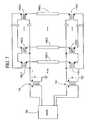
- FIG. 7is a schematic diagram of one embodiment of a backlight system with multiple lamps driven in a differential configuration.
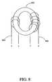
- FIG. 8illustrates one embodiment of a toroidal core balancing transformer in accordance with the present invention.
- FIG. 9is one embodiment of a ring balancer with a single turn secondary winding loop.
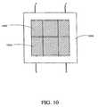
- FIG. 10is one embodiment of a balancing transformer using an E-core based structure.
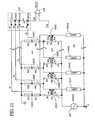
- FIG. 11illustrates one embodiment of a fault detection circuit coupled to a ring balancer to detect presence of non-operational lamps.
- FIG. 1is a schematic diagram of one embodiment of a backlight system with a ring balancer coupled between an input AC source 100 and high voltage terminals of multiple lamps (LAMP 1 , LAMP 2 , . . . LAMPK) shown as lamps 104 ( 1 )- 104 ( k ) (collectively the lamps 104 ).
- the ring balancercomprises multiple balancing transformers (Tb 1 , Tb 2 , . . . Tbk) shown as balancing transformers 102 ( 1 )- 102 ( k ) (collectively the balancing transformers 102 ).
- Each of the balancing transformers 102is designated for a different one of the lamps 104 .
- the balancing transformers 102have respective primary windings coupled in series with their designated lamps 104 .
- the balancing transformers 102have respective secondary windings connected in series with each other and in phase to form a short circuit (or closed) loop. The polarity of the secondary windings is aligned so that the voltages induced in the secondary windings are in phase and add up together in the closed loop.
- the primary winding-lamp combinationsare coupled in parallel to the input AC source 100 .
- the input AC source 100is shown as a single voltage source in FIG. 1 , and the primary windings are coupled between the high voltage terminals of the respective lamps 104 and the positive node of the input AC source 100 .
- the primary winding-lamp combinationsare divided into subgroups with each subgroup comprising one or more parallel primary winding-lamp combinations. The subgroups can be driven by different voltage sources which are synchronized with each other.
- N 1k and I 1kdenote the primary turns and primary current respectively of the Kth balancing transformer.
- N 2k and I 2kdenote the secondary turns and secondary current respectively of the Kth balancing transformer.
- the primary currents and hence the lamp currents conducted by the respective lamps 104can be controlled proportionally with the turns ratio (N 21 /N 11 , N 22 /N 12 , . . . N 2k /N 1k ) of the balancing transformers 102 according to Eqn. 2.
- the turns ratioN 21 /N 11 , N 22 /N 12 , . . . N 2k /N 1k
- the proposed backlighting systemcan reduce the short circuit current when a lamp is shorted.
- the proposed backlighting systemfacilitates automatic lamp striking.
- additional voltage across its designated primary winding, in phase with the input AC source 100will be developed to help to strike the lamp.
- the additional voltageis generated by a flux increase due to the decrease in primary current.
- the current flowing in the corresponding primary winding of the balancing transformeris substantially zero.
- the ampere turns balancing equation of Eqn. 1cannot be maintained in such a situation.
- Excessive magnetizing force resulted from the unbalanced ampere turnswill generate an additional voltage in the primary winding of the balancing transformer.
- the additional voltageadds in phase with the input AC source 100 to result in an automatic increase of the voltage across the non-ignited lamp, thus helping the lamp to strike.
- the application of this inventionis not limited to multiple lamps (e.g., CCFLs) in backlight systems. It also applies to other types of applications and different types of loads in which multiple loads are connected to a common AC source in parallel and current matching among the loads is desired.
- FIGS. 2-7show examples of other embodiments of backlight systems using at least one ring balancer for current matching.
- other types of configurationscan also be formulated based on the same concept, depending on the actual backlight system construction. For instance, it is possible to balance the current of multiple lamps when they are driven by more than one AC sources with this concept, as long as the multiple AC sources are synchronized and maintain the phase relations according to the principle of this concept.
- FIG. 2is a schematic diagram of one embodiment of a backlight system with a ring balancer coupled between ground and return terminals of multiple lamps (LAMP 1 , LAMP 2 , . . . LAMP K) shown as lamps 208 ( 1 )- 208 ( k ) (collectively the lamps 208 ).
- the ring balancercomprises multiple balancing transformers (Tb 1 , Tb 2 , . . . Tbk) shown as balancing transformers 210 ( 1 )- 210 ( k ) (collectively the balancing transformers 210 ).
- Each of the balancing transformers 210is designated for a different one of the lamps 208 .
- the balancing transformers 210have respective primary windings coupled in series with their designated lamps 208 and respective secondary windings connected in a serial ring.
- the embodiment shown in FIG. 2is substantially similar to the embodiment shown in FIG. 1 except the ring balancer is coupled to return sides of the respective lamps 208 .
- the primary windingsare coupled between the respective return terminals of the lamps 208 and ground.
- the high voltage terminals of the lamps 208are coupled to a positive terminal of a voltage source 200 .
- the voltage source 200is shown in further detail as an inverter comprising a controller 202 , a switching network 204 and an output transformer stage 206 .
- the switching network 204accepts a direct current (DC) input voltage (V-IN) and is controlled by driving signals from the controller 202 to generate an AC signal for the output transformer stage 206 .
- the output transformer stage 206includes a single transformer with a secondary winding referenced to ground to drive the lamps 208 and ring balancer in a single-ended configuration.
- the ring balancerfacilitates automatic increase of the voltage across a non-stricken lamp to guarantee reliable striking of lamps in backlight systems without additional components or mechanism.
- Lamp strikingis one of the difficult problems in the operation of multiple lamps in a parallel configuration.
- the headroom typically reserved for striking operations in an inverter designcan be reduced to achieve better efficiency of the inverter and lower crest factor of the lamp current through better optimization of transformer design in the output transformer stage 206 , better utilization of switching duty cycle by the controller 202 , lower transformer voltage stress, etc.
- FIG. 3is a schematic diagram of one embodiment of a backlight system with multiple pairs of lamps in a parallel configuration and a ring balancer inserted between the pairs of lamps.
- a first group of lampsLAMP 1 A, LAMP 2 A, . . . LAMP kA
- lamps 304 ( 1 )- 304 ( k )are coupled between a high voltage terminal of an output transformer (TX) 302 and the ring balancer.
- TXoutput transformer
- a second group of lamps(LAMP 1 B, LAMP 2 B, . . .
- LAMP kBshown as lamps 308 ( 1 )- 308 ( k ) (collectively the second group of lamps 308 ) are coupled between the ring balancer and a return terminal (or ground).
- a driver circuit 300drives the output transformer 302 to provide an AC source for powering the first and second groups of lamps 304 , 308 .
- the ring balancercomprises a plurality of balancing transformers (Tb 1 , Tb 2 , . . . Tbk) shown as balancing transformers 306 ( 1 )- 306 ( k ) (collectively the balancing transformers 306 ).
- Each of the balancing transformers 306is designated for a pair of lamps, one lamp from the first group of lamps 304 and one lamp from the second group of lamps 308 .
- the balancing transformers 306have respective secondary windings serially connected in a closed loop. In this configuration, the number of balancing transformers is advantageously half the number of lamps to be balanced.
- the balancing transformers 306have respective primary windings inserted in series between their designated pairs of lamps.
- the first group of lamps 304 and the second group of lamps 308are effectively coupled in series by pairs with a different primary winding inserted between each pair.
- the pairs of lamps with respective designated primary windingsare coupled in parallel across the output transformer 302 .
- FIG. 4is a schematic diagram of one embodiment of a backlight system with multiple lamps driven in a floating configuration.
- a driver circuit 400drives an output transformer stage comprising of two transformers 402 , 404 with respective primary windings connected in series and respective secondary windings connected in series.
- the serially connected secondary windings of the output transformers 402 , 404are coupled across a ring balancer and a group of lamps (LAMP 1 , LAMP 2 , . . . LAMP k) shown as lamps 408 ( 1 )- 408 ( k ) (collectively the lamp 408 ).
- the ring balancercomprise a plurality of balancing transformers (Tb 1 , Tb 2 , . . . Tbk) shown as balancing transformers 406 ( 1 )- 406 ( k ) (collectively the balancing transformers 406 ).
- Each of the balancing transformers 406is dedicated to a different one of the lamps 408 .
- the balancing transformers 406have respective primary windings connected in series with their dedicated lamps 408 and respective secondary windings connected in series with each other in a closed loop.
- the primary winding-lamp combinationsare coupled in parallel across the serially connected secondary windings of the output transformers 402 , 404 .
- the lamps 408are driven in a floating configuration without reference to a ground terminal.
- FIG. 5is a schematic diagram of another embodiment of a backlight system with multiple lamps driven in a floating configuration.
- FIG. 5illustrates a selective combination of FIGS. 3 and 4 .
- a ring balanceris inserted between multiple pairs of serial lamps connected in parallel across a common source.
- the common sourceincludes a driver circuit 500 coupled to an output transformer stage comprising of two serially connected transformers 502 , 504 .
- a first group of lampsshown as lamps 506 ( 1 )- 506 ( k ) (collectively the first group of lamps 506 ) are coupled between a first terminal the output transformer stage and the ring balancer.
- a second group of lampsshown as lamps 510 ( 1 )- 510 ( k ) (collectively the second group of lamps 510 ) are coupled between the ring balancer and a second terminal of the output transformer stage.
- the ring balancercomprises a plurality of balancing transformers (Tb 1 , Tb 2 , . . .
- Tbkshown as balancing transformers 508 ( 1 )- 508 ( k ) (collectively the balancing transformers 508 ).
- Each of the balancing transformers 508is designated for a pair of lamps, one lamp from the first group of lamps 506 and one lamp from the second group of lamps 510 .
- the balancing transformers 508have respective primary windings inserted in series between their designated pairs of lamps.
- the first group of lamps 506 and the second group of lamps 510are effectively coupled in series by pairs with a different primary winding inserted between each pair.
- the pairs of lamps with respective designated primary windingsare coupled in parallel across the serially connected secondary windings of the transformers 502 , 504 in the output transformer stage.
- the balancing transformers 508have respective secondary windings serially connected in a closed loop.
- the number of balancing transformers 508is advantageously half the number of lamps 506 , 510 to be balanced in this configuration.
- FIG. 6is a schematic diagram of one embodiment of a backlight system with two ring balancers, one at each end of parallel lamps shown as lamps 606 ( 1 )- 606 ( k ) (collectively the lamps 606 ).
- the first ring balancercomprises a first plurality of balancing transformers shown as balancing transformers 604 ( 1 )- 604 ( k ) (collectively the first set of balancing transformers 604 ). Secondary windings in the first set of balancing transformers 604 are serially coupled together in a first closed ring.
- the second ring balancercomprises a second plurality of balancing transformers shown as balancing transformers 608 ( 1 )- 608 ( k ) (collectively the second set of balancing transformers 608 ). Secondary windings in the second set of balancing transformers 608 are serially coupled together in a second closed ring.
- Each of the lamps 606is associated with two different balancing transformers, one from the first set of balancing transformers 604 and one from the second set of balancing transformers 608 .
- primary windings in the first set of balancing transformers 604are coupled in series with their associated lamps 606 and corresponding primary windings in the second set of balancing transformers 608 .
- the serial combinations of lamp with different primary windings on both endsare coupled in parallel across a common source.
- the common sourcee.g., an inverter
- the output transformer 602may drive the lamps 606 and ring balancers in a floating configuration or have a secondary winding with one terminal connected to ground as shown in FIG. 6 .
- FIG. 7is a schematic diagram of one embodiment of a backlight system with multiple lamps driven in a differential configuration.
- the embodimentincludes two ring balancers coupled on respective ends of a plurality of lamps shown as lamps 708 ( 1 )- 708 ( k ) (collectively the lamps 708 ).
- the connections between the ring balancers and the lamps 708are substantially similar to corresponding connections shown in FIG. 6 .
- the first ring balancerincludes a plurality of balancing transformers shown as balancing transformers 706 ( 1 )- 706 ( k ) (collectively the first group of balancing transformers 706 ).
- the first group of balancing transformers 706have respective secondary windings coupled in a closed loop to balance currents among the lamps 708 .
- the second ring balancerincludes a plurality of balancing transformers shown as balancing transformers 710 ( 1 )- 710 ( k ) (collectively the second group of balancing transformers 710 ).
- the second group of balancing transformers 710have respective secondary windings coupled in another closed loop to reinforce or provide redundancy in balancing currents among the lamps 708 .
- Each of the lamps 708is associated with two different balancing transformers, one from the first group of balancing transformers 706 and one from the second group of balancing transformers 710 .
- Primary windings in the first group of balancing transformers 706are coupled in series with their associated lamps 708 and corresponding primary windings in the second group of balancing transformers 710 .
- the serial combinations of lamp with different primary windings on both endsare coupled in parallel across a common source.
- the common sourcee.g., a split phase inverter
- the common sourceis shown as a driver 700 coupled to a pair of output transformers 702 , 704 which are driven by phase-shifted signals or signals with other switching patterns to produce differential signals (Va, Vb) across secondary windings of the respective output transformers 702 , 704 .
- FIG. 8illustrates one embodiment of a toroidal core balancing transformer in accordance with the present invention.
- a primary winding 802 and a secondary winding 804are directly wound on the toroidal core 800 .
- the primary winding 802 on the toroidal core 800is wound progressively, instead of in overlapped multiple layers, to avoid high potential between primary turns.
- the secondary winding 804can be likewise wound progressively.
- the wire gauge for the windings 802 , 804should be selected based on the current rating, which can be derived from Eqn. 1 and Eqn. 2.
- the balancing transformers in a ring balanceradvantageously work with any number of secondary turns or primary-to-secondary turns ratios. A good balancing result can be obtained with different turns ratios according to the relationship established in Eqn. 1 and Eqn. 2.
- a relatively small number of turnse.g., 1-10 turns
- Another factor to determine the desired number of secondary turnsis the desired voltage signal level across the secondary winding 804 for a fault detection circuit, which is discussed in further detail below.
- FIG. 9is one embodiment of a ring balancer with a single turn secondary winding loop 904 .
- the ring balancercomprises a plurality of balancing transformers using toroidal cores shown as toroidal cores 900 ( 1 )- 900 ( k ) (collective the toroidal cores 900 ).
- Primary windings shown as primary windings 902 ( 1 )- 902 ( k ) (collectively the primary windings 902 )are progressively wound on the respective toroidal cores 900 .
- a single insulated wiregoes through the inner holes of the toridal cores to 900 form a single turn secondary winding loop 904 .
- FIG. 10is one embodiment of a balancing transformer using an E-core based structure 1000 .
- a winding bobbinis used.
- the bobbinis divided into two sections with a first section 1002 for the primary winding and a second section 1004 for the secondary winding.
- One advantage of such a winding arrangementis better insulation between the primary and secondary windings because a high voltage (e.g., a few hundred volts) can be induced in the primary windings during striking or open lamp conditions.
- Another advantageis reduced cost due to a simpler manufacturing process.
- An alternative embodiment of the balancing transformeroverlaps the primary winding with the secondary winding to provide tight coupling between the primary and secondary windings. Insulation between the primary and secondary windings, manufacturing process, etc. becomes more complex with overlapping primary and secondary windings.
- the balancing transformers used in a ring balancercan be constructed with different types of magnetic cores and winding configurations.
- the balancing transformersare realized with relatively high permeability materials (e.g., materials with initial relative permeability greater than 5,000).
- the relatively high permeability materialsprovide a relatively high inductance with a given window space at the rated operating current.
- the magnetizing inductance of the primary windingshould be as high as possible, so that during operation the magnetizing current can be small enough to be negligible.
- the core lossis normally higher for relatively high permeability materials than for relatively low permeability materials at a given operating frequency and flux density.
- the working flux density of the transformer coreis relatively low during normal operations of the balancing transformer because the magnitude of the induced voltage in the primary winding, which compensates for the variations in operating lamp voltage, is relatively low.
- the use of relatively high permeability materials in the balancing transformeradvantageously provides relatively high inductance while maintaining the operational loss of the transformer at a reasonably low level.
- FIG. 11illustrates one embodiment of a fault detection circuit coupled to a ring balancer to detect presence of non-operational lamps.
- the configuration of the backlight system shown in FIG. 11is substantially similar to the one shown in FIG. 1 with multiple lamps 104 , a common source 100 and the ring balancer comprising a plurality of balancing transformers 102 .
- the backlight system in FIG. 11further includes the fault detection circuit to monitor voltages at the secondary windings of the balancing transformers 102 to detect a non-operating lamp condition.
- Lamp currents conducted by the multiple lamps 104are balanced by connecting designated primary windings of the balancing transformers 102 in series with each lamp while secondary windings of the balancing transformers 102 are connected together in a serial loop with a predefined polarity.
- a common current circulating in each of the secondary windingsforces currents in the primary windings to equalize with each other, thereby keeping the lamp currents balanced.
- Any error current in a primary windingeffectively generates a balancing voltage in that primary winding to compensate for tolerances in lamp operating voltages which can vary up to 20% from the nominal value.
- a corresponding voltagedevelops in the associated secondary winding and is proportional to the balancing voltage.
- the voltage signal from the secondary windings of the balancing transformers 102can be monitored to detect open lamp or shorted lamp conditions. For example, when a lamp is open, the voltages in both the primary and secondary windings of the corresponding balancing transformer 102 will rise significantly. When a short circuit occurs with a particular lamp, voltages in transformer windings associated with non-shorted lamps rise. A level detection circuit can be used to detect the rising voltage to determine the fault condition.
- open lamp or shorted lamp conditionscan be distinctively detected by sensing voltages at the secondary windings of the balancing transformers 102 and comparing the sensed voltages to a predetermined threshold.
- voltages at the secondary windingsare sensed with respective resistor dividers shown as resistor dividers 1100 ( 1 )- 1100 ( k ) (collectively the resistors dividers 1100 ).
- the resistor dividers 1100each comprising of a pair of resistors connected in series, are coupled between predetermined terminals of the respective secondary windings and ground.
- the common nodes between the respective pair of resistorsprovide sensed voltages (V 1 , V 2 , . . .
- the combining circuit 1102includes a plurality of isolation diodes shown as isolation diodes 1104 ( 1 )- 1104 ( k ) (collectively the isolation diodes 1104 ).
- the isolation diodes 1104form a diode OR-ed circuit with anodes individually coupled to the respective sensed voltages and cathodes commonly connected to generate a feedback voltage (Vfb) corresponding to the highest sensed voltage.
- the feedback voltageis provided to a positive input terminal of a comparator 1106 .
- a reference voltage(Vref) is provided to a negative input terminal of the comparator 1106 .
- the comparator 1106outputs a fault signal (FAULT) to indicate the presence of one or more non-operating lamps.
- the fault signalcan be used to turn off the common source powering the lamps 104 .
- the fault detection circuit described aboveadvantageously has no direct connection to the lamps 104 , thus reducing the complexity and cost associated with this feature. It should be noted that many different types of fault detection circuits can be designed to detect fault lamp conditions by monitoring the voltages at the secondary windings in a ring balancer.
Landscapes
- Engineering & Computer Science (AREA)
- Power Engineering (AREA)
- Circuit Arrangements For Discharge Lamps (AREA)
- Circuit Arrangement For Electric Light Sources In General (AREA)
- Liquid Crystal (AREA)
Abstract
Description
N11·I11=N21·I21; N12·I22; . . . N1k·I1k=N2k·I2k. (Eqn. 1)
I11=(N21/N11)·I21; I12=(N22/N12)·I22; . . . I1k=(N2k/N1k)·I2k. (Eqn. 2)
I21=I22= . . . =I2k=Ix. (Eqn. 3)
Claims (20)
Priority Applications (2)
| Application Number | Priority Date | Filing Date | Title |
|---|---|---|---|
| US12/497,401US7932683B2 (en) | 2003-10-06 | 2009-07-02 | Balancing transformers for multi-lamp operation |
| US13/084,229US8222836B2 (en) | 2003-10-06 | 2011-04-11 | Balancing transformers for multi-lamp operation |
Applications Claiming Priority (4)
| Application Number | Priority Date | Filing Date | Title |
|---|---|---|---|
| US50893203P | 2003-10-06 | 2003-10-06 | |
| US10/959,667US7294971B2 (en) | 2003-10-06 | 2004-10-05 | Balancing transformers for ring balancer |
| US11/937,693US7560875B2 (en) | 2003-10-06 | 2007-11-09 | Balancing transformers for multi-lamp operation |
| US12/497,401US7932683B2 (en) | 2003-10-06 | 2009-07-02 | Balancing transformers for multi-lamp operation |
Related Parent Applications (1)
| Application Number | Title | Priority Date | Filing Date |
|---|---|---|---|
| US11/937,693ContinuationUS7560875B2 (en) | 2003-10-06 | 2007-11-09 | Balancing transformers for multi-lamp operation |
Related Child Applications (1)
| Application Number | Title | Priority Date | Filing Date |
|---|---|---|---|
| US13/084,229ContinuationUS8222836B2 (en) | 2003-10-06 | 2011-04-11 | Balancing transformers for multi-lamp operation |
Publications (2)
| Publication Number | Publication Date |
|---|---|
| US20090267521A1 US20090267521A1 (en) | 2009-10-29 |
| US7932683B2true US7932683B2 (en) | 2011-04-26 |
Family
ID=34465091
Family Applications (5)
| Application Number | Title | Priority Date | Filing Date |
|---|---|---|---|
| US10/958,668Expired - Fee RelatedUS7242147B2 (en) | 2003-10-06 | 2004-10-05 | Current sharing scheme for multiple CCF lamp operation |
| US10/959,667Expired - LifetimeUS7294971B2 (en) | 2003-10-06 | 2004-10-05 | Balancing transformers for ring balancer |
| US11/937,693Expired - LifetimeUS7560875B2 (en) | 2003-10-06 | 2007-11-09 | Balancing transformers for multi-lamp operation |
| US12/497,401Expired - Fee RelatedUS7932683B2 (en) | 2003-10-06 | 2009-07-02 | Balancing transformers for multi-lamp operation |
| US13/084,229Expired - Fee RelatedUS8222836B2 (en) | 2003-10-06 | 2011-04-11 | Balancing transformers for multi-lamp operation |
Family Applications Before (3)
| Application Number | Title | Priority Date | Filing Date |
|---|---|---|---|
| US10/958,668Expired - Fee RelatedUS7242147B2 (en) | 2003-10-06 | 2004-10-05 | Current sharing scheme for multiple CCF lamp operation |
| US10/959,667Expired - LifetimeUS7294971B2 (en) | 2003-10-06 | 2004-10-05 | Balancing transformers for ring balancer |
| US11/937,693Expired - LifetimeUS7560875B2 (en) | 2003-10-06 | 2007-11-09 | Balancing transformers for multi-lamp operation |
Family Applications After (1)
| Application Number | Title | Priority Date | Filing Date |
|---|---|---|---|
| US13/084,229Expired - Fee RelatedUS8222836B2 (en) | 2003-10-06 | 2011-04-11 | Balancing transformers for multi-lamp operation |
Country Status (10)
| Country | Link |
|---|---|
| US (5) | US7242147B2 (en) |
| EP (1) | EP1671521B1 (en) |
| JP (1) | JP4658061B2 (en) |
| KR (1) | KR101085579B1 (en) |
| CN (1) | CN1887034B (en) |
| AT (1) | ATE458382T1 (en) |
| DE (1) | DE602004025593D1 (en) |
| ES (1) | ES2340169T3 (en) |
| TW (1) | TWI276370B (en) |
| WO (1) | WO2005038828A2 (en) |
Families Citing this family (132)
| Publication number | Priority date | Publication date | Assignee | Title |
|---|---|---|---|---|
| US6114814A (en)* | 1998-12-11 | 2000-09-05 | Monolithic Power Systems, Inc. | Apparatus for controlling a discharge lamp in a backlighted display |
| US6979959B2 (en) | 2002-12-13 | 2005-12-27 | Microsemi Corporation | Apparatus and method for striking a fluorescent lamp |
| US7589478B2 (en)* | 2003-02-10 | 2009-09-15 | Masakazu Ushijima | Inverter circuit for discharge lamps for multi-lamp lighting and surface light source system |
| JP2004335443A (en)* | 2003-02-10 | 2004-11-25 | Masakazu Ushijima | Inverter circuit for discharge tube for multiple lamp lighting, and surface light source system |
| US7187139B2 (en) | 2003-09-09 | 2007-03-06 | Microsemi Corporation | Split phase inverters for CCFL backlight system |
| US7183727B2 (en) | 2003-09-23 | 2007-02-27 | Microsemi Corporation | Optical and temperature feedbacks to control display brightness |
| ATE458382T1 (en) | 2003-10-06 | 2010-03-15 | Microsemi Corp | POWER SHARING SCHEMATIC AND DEVICE FOR MULTIPLE CCF LAMP OPERATION |
| US7279851B2 (en)* | 2003-10-21 | 2007-10-09 | Microsemi Corporation | Systems and methods for fault protection in a balancing transformer |
| WO2005045311A2 (en)* | 2003-11-03 | 2005-05-19 | Monolithic Power Systems, Inc. | Driver for light source having integrated photosensitive elements for driver control |
| US7183724B2 (en)* | 2003-12-16 | 2007-02-27 | Microsemi Corporation | Inverter with two switching stages for driving lamp |
| TWI254270B (en)* | 2004-01-15 | 2006-05-01 | Hon Hai Prec Ind Co Ltd | Lighting apparatus formed by serially driving lighting units |
| US7468722B2 (en) | 2004-02-09 | 2008-12-23 | Microsemi Corporation | Method and apparatus to control display brightness with ambient light correction |
| JP4101228B2 (en)* | 2004-03-19 | 2008-06-18 | 昌和 牛嶋 | Discharge tube parallel lighting system for surface light source |
| JP4658110B2 (en)* | 2004-03-19 | 2011-03-23 | 昌和 牛嶋 | Discharge tube parallel lighting system for surface light source |
| US7112929B2 (en) | 2004-04-01 | 2006-09-26 | Microsemi Corporation | Full-bridge and half-bridge compatible driver timing schedule for direct drive backlight system |
| WO2005101920A2 (en) | 2004-04-07 | 2005-10-27 | Microsemi Corporation | A primary side current balancing scheme for multiple ccf lamp operation |
| US7755595B2 (en) | 2004-06-07 | 2010-07-13 | Microsemi Corporation | Dual-slope brightness control for transflective displays |
| US7368880B2 (en)* | 2004-07-19 | 2008-05-06 | Intersil Americas Inc. | Phase shift modulation-based control of amplitude of AC voltage output produced by double-ended DC-AC converter circuitry for powering high voltage load such as cold cathode fluorescent lamp |
| TWI306725B (en)* | 2004-08-20 | 2009-02-21 | Monolithic Power Systems Inc | Minimizing bond wire power losses in integrated circuit full bridge ccfl drivers |
| JP4866397B2 (en)* | 2004-09-01 | 2012-02-01 | 昌和 牛嶋 | Parallel lighting module and balancer coil for discharge tubes |
| JP4219340B2 (en) | 2004-09-01 | 2009-02-04 | 昌和 牛嶋 | Parallel lighting module and balancer coil for discharge tubes |
| JP4561254B2 (en)* | 2004-09-03 | 2010-10-13 | セイコーエプソン株式会社 | Device management system |
| JP2006108667A (en)* | 2004-09-30 | 2006-04-20 | Greatchip Technology Co Ltd | Inverter transformer |
| TWI318084B (en) | 2004-10-13 | 2009-12-01 | Monolithic Power Systems Inc | Methods and protection schemes for driving discharge lamps in large panel applications |
| CN101668374A (en)* | 2004-11-05 | 2010-03-10 | 太阳诱电株式会社 | Lamp-lighting apparatus |
| JP2006156338A (en)* | 2004-11-05 | 2006-06-15 | Taiyo Yuden Co Ltd | Lamp lighting device |
| US20060119293A1 (en)* | 2004-12-03 | 2006-06-08 | Chun-Kong Chan | Lamp load-sharing circuit |
| TWI345430B (en)* | 2005-01-19 | 2011-07-11 | Monolithic Power Systems Inc | Method and apparatus for dc to ac power conversion for driving discharge lamps |
| US7560872B2 (en)* | 2005-01-31 | 2009-07-14 | Intersil Americas Inc. | DC-AC converter having phase-modulated, double-ended, half-bridge topology for powering high voltage load such as cold cathode fluorescent lamp |
| US7564193B2 (en) | 2005-01-31 | 2009-07-21 | Intersil Americas Inc. | DC-AC converter having phase-modulated, double-ended, full-bridge topology for powering high voltage load such as cold cathode fluorescent lamp |
| US7061183B1 (en)* | 2005-03-31 | 2006-06-13 | Microsemi Corporation | Zigzag topology for balancing current among paralleled gas discharge lamps |
| US7173382B2 (en)* | 2005-03-31 | 2007-02-06 | Microsemi Corporation | Nested balancing topology for balancing current among multiple lamps |
| US20060244395A1 (en)* | 2005-05-02 | 2006-11-02 | Taipale Mark S | Electronic ballast having missing lamp detection |
| TWI326564B (en)* | 2005-05-03 | 2010-06-21 | Darfon Electronics Corp | Power supply circuit for lamp and transformer therefor |
| TWI330346B (en)* | 2005-06-15 | 2010-09-11 | Chi Mei Optoelectronics Corp | Liquid crystal display, backlight module and lamp driving apparatus thereof |
| US7196483B2 (en)* | 2005-06-16 | 2007-03-27 | Au Optronics Corporation | Balanced circuit for multi-LED driver |
| US7439685B2 (en)* | 2005-07-06 | 2008-10-21 | Monolithic Power Systems, Inc. | Current balancing technique with magnetic integration for fluorescent lamps |
| TWI284332B (en) | 2005-07-06 | 2007-07-21 | Monolithic Power Systems Inc | Equalizing discharge lamp currents in circuits |
| TWI350128B (en)* | 2005-08-10 | 2011-10-01 | Au Optronics Corp | Lamp drive circuit |
| US7446485B2 (en)* | 2005-08-24 | 2008-11-04 | Beyond Innovation Technology Co., Ltd. | Multi-lamp driving system |
| US7420829B2 (en) | 2005-08-25 | 2008-09-02 | Monolithic Power Systems, Inc. | Hybrid control for discharge lamps |
| CN100426056C (en)* | 2005-08-26 | 2008-10-15 | 鸿富锦精密工业(深圳)有限公司 | Multiple lamp tube driving system and method |
| US7253569B2 (en)* | 2005-08-31 | 2007-08-07 | 02Micro International Limited | Open lamp detection in an EEFL backlight system |
| US7291991B2 (en)* | 2005-10-13 | 2007-11-06 | Monolithic Power Systems, Inc. | Matrix inverter for driving multiple discharge lamps |
| CN1953631A (en)* | 2005-10-17 | 2007-04-25 | 美国芯源系统股份有限公司 | A DC/AC power supply device for the backlight application of cold-cathode fluorescent lamp |
| US7372213B2 (en)* | 2005-10-19 | 2008-05-13 | O2Micro International Limited | Lamp current balancing topologies |
| US7423384B2 (en) | 2005-11-08 | 2008-09-09 | Monolithic Power Systems, Inc. | Lamp voltage feedback system and method for open lamp protection and shorted lamp protection |
| KR101147181B1 (en)* | 2005-11-17 | 2012-05-25 | 삼성전자주식회사 | Inverter circuit, backlight assembly and liquid crystal display having the same |
| KR101147179B1 (en)* | 2005-11-17 | 2012-05-25 | 삼성전자주식회사 | Inverter circuit, backlight, and lcd |
| US7414371B1 (en) | 2005-11-21 | 2008-08-19 | Microsemi Corporation | Voltage regulation loop with variable gain control for inverter circuit |
| KR101164199B1 (en)* | 2005-11-30 | 2012-07-11 | 삼성전자주식회사 | Inverter circuit, backlight device, and liquid crystal display device using the same |
| KR101242124B1 (en)* | 2005-11-30 | 2013-03-12 | 삼성디스플레이 주식회사 | Back light assembly and liquid crystal display unit using the same |
| KR20070059721A (en)* | 2005-12-07 | 2007-06-12 | 삼성전자주식회사 | Inverter circuit, backlight assembly and liquid crystal display with same |
| US7394203B2 (en)* | 2005-12-15 | 2008-07-01 | Monolithic Power Systems, Inc. | Method and system for open lamp protection |
| KR20070074999A (en)* | 2006-01-11 | 2007-07-18 | 삼성전자주식회사 | Apparatus for driving lamp and liquid crystal display having the same |
| US8344658B2 (en)* | 2006-01-19 | 2013-01-01 | International Rectifier Corporation | Cold-cathode fluorescent lamp multiple lamp current matching circuit |
| US7268500B2 (en)* | 2006-01-20 | 2007-09-11 | Logah Technology Corp. | Control device for multiple lamp currents of liquid crystal display backlight source |
| US7429835B2 (en)* | 2006-02-07 | 2008-09-30 | Himax Technologies Limited | Backlight module driver circuit |
| JP2007280916A (en)* | 2006-03-17 | 2007-10-25 | Taiyo Yuden Co Ltd | Lamp lighting device |
| JP4664226B2 (en) | 2006-04-04 | 2011-04-06 | スミダコーポレーション株式会社 | Discharge tube drive circuit |
| US7619371B2 (en)* | 2006-04-11 | 2009-11-17 | Monolithic Power Systems, Inc. | Inverter for driving backlight devices in a large LCD panel |
| JP2007288872A (en) | 2006-04-13 | 2007-11-01 | Rohm Co Ltd | Inverter device, light-emitting apparatus employing same, and image display apparatus |
| US7804254B2 (en)* | 2006-04-19 | 2010-09-28 | Monolithic Power Systems, Inc. | Method and circuit for short-circuit and over-current protection in a discharge lamp system |
| TWI391029B (en)* | 2007-12-31 | 2013-03-21 | Ampower Technology Co Ltd | System for driving a plurality of discharge lamps |
| US7830100B2 (en)* | 2006-04-28 | 2010-11-09 | Ampower Technology Co., Ltd. | System for driving a plurality of lamps |
| JP4841481B2 (en) | 2006-05-18 | 2011-12-21 | スミダコーポレーション株式会社 | Balance transformer |
| JP2007317503A (en)* | 2006-05-25 | 2007-12-06 | Sanken Electric Co Ltd | Discharge lamp lighting device |
| CN101080128B (en)* | 2006-05-26 | 2012-10-03 | 昂宝电子(上海)有限公司 | Cycle framework driving system and method of multi-tube CCFL and/or EEFL |
| US7420337B2 (en)* | 2006-05-31 | 2008-09-02 | Monolithic Power Systems, Inc. | System and method for open lamp protection |
| CN100578595C (en)* | 2006-06-19 | 2010-01-06 | 台达电子工业股份有限公司 | Current equalizing circuit |
| JP4870484B2 (en)* | 2006-06-26 | 2012-02-08 | スミダコーポレーション株式会社 | Inverter transformer |
| KR100721170B1 (en) | 2006-07-03 | 2007-05-23 | 삼성전기주식회사 | Current equalization circuit |
| US7569998B2 (en) | 2006-07-06 | 2009-08-04 | Microsemi Corporation | Striking and open lamp regulation for CCFL controller |
| JP4584880B2 (en) | 2006-07-27 | 2010-11-24 | スミダコーポレーション株式会社 | Inverter circuit |
| WO2008013185A1 (en)* | 2006-07-28 | 2008-01-31 | Panasonic Corporation | Discharge lamp operating system |
| DE102006040026B4 (en) | 2006-08-25 | 2015-06-18 | Minebea Co., Ltd. | Transformer for current balancing |
| JP2008066071A (en)* | 2006-09-06 | 2008-03-21 | Taiyo Yuden Co Ltd | Lamp driving device |
| KR20080024000A (en)* | 2006-09-12 | 2008-03-17 | 삼성전자주식회사 | Backlight module, drive circuit of light emitting element, and liquid crystal display |
| TW200814853A (en)* | 2006-09-13 | 2008-03-16 | Greatchip Technology Co Ltd | Current balanced circuit for discharge lamp |
| US8054001B2 (en)* | 2006-09-18 | 2011-11-08 | O2Micro Inc | Circuit structure for LCD backlight |
| TWI314743B (en)* | 2006-09-28 | 2009-09-11 | Darfon Electronics Corp | Transformer and multi-lamp driving circuit using the same |
| TWI382384B (en)* | 2006-10-25 | 2013-01-11 | Gigno Technology Co Ltd | Inverter and driving device of backlight module |
| US7893628B2 (en)* | 2006-11-22 | 2011-02-22 | Minebea Co., Ltd. | Electronic circuit for operating a plurality of gas discharge lamps at a common voltage source |
| KR100849795B1 (en)* | 2007-03-26 | 2008-07-31 | 삼성전기주식회사 | Current balanced circuit for easy electrical connection |
| GB2447963B (en)* | 2007-03-29 | 2011-11-16 | E2V Tech | High frequency transformer for high voltage applications |
| KR100826413B1 (en)* | 2007-04-27 | 2008-04-29 | 삼성전기주식회사 | Multi lamp drive |
| CN101311793B (en)* | 2007-05-25 | 2010-07-07 | 群康科技(深圳)有限公司 | Backlight module |
| US8058809B2 (en)* | 2007-07-02 | 2011-11-15 | O2Micro, Inc. | Circuits and methods for balancing current among multiple loads |
| CN101365280B (en)* | 2007-08-09 | 2014-03-12 | 皇家飞利浦电子股份有限公司 | Lamp driving circuit |
| JP2009044915A (en)* | 2007-08-10 | 2009-02-26 | Sanken Electric Co Ltd | Power supply device |
| CN101409972B (en)* | 2007-10-12 | 2016-10-05 | 昂宝电子(上海)有限公司 | For multiple cold cathode fluorescence lamps and/or the drive system of external-electrode fluorescent lamp and method |
| US20100057627A1 (en)* | 2008-09-04 | 2010-03-04 | Lutnick Howard W | Non-firm orders in electronic marketplaces |
| CN101453818B (en)* | 2007-11-29 | 2014-03-19 | 杭州茂力半导体技术有限公司 | Discharge lamp circuit protection and regulation apparatus |
| TWI409739B (en)* | 2008-01-22 | 2013-09-21 | Innolux Corp | Flat display and backlight module thereof |
| DE102008005792B4 (en) | 2008-01-23 | 2010-04-08 | Minebea Co., Ltd. | Electronic circuit and method for operating a plurality of gas discharge lamps at a common voltage source |
| TW200939886A (en) | 2008-02-05 | 2009-09-16 | Microsemi Corp | Balancing arrangement with reduced amount of balancing transformers |
| TWI408636B (en)* | 2008-02-14 | 2013-09-11 | Au Optronics Corp | Light driving circuit device and backlight device |
| KR100945998B1 (en)* | 2008-04-11 | 2010-03-09 | 삼성전기주식회사 | Multi-lamp driver with integrated current balance and detection |
| TWM341229U (en)* | 2008-04-23 | 2008-09-21 | Darfon Electronics Corp | Backlight module |
| JP2010029058A (en) | 2008-06-05 | 2010-02-04 | Rohm Co Ltd | Inverter device, drive device for fluorescent lamp and control method thereof, light-emitting apparatus employing them, and display |
| JP4586905B2 (en)* | 2008-08-13 | 2010-11-24 | ソニー株式会社 | Light emitting diode drive device |
| US8093839B2 (en) | 2008-11-20 | 2012-01-10 | Microsemi Corporation | Method and apparatus for driving CCFL at low burst duty cycle rates |
| US8189313B1 (en)* | 2008-12-03 | 2012-05-29 | Analog Devices, Inc. | Fault detection and handling for current sources |
| KR20100066603A (en)* | 2008-12-10 | 2010-06-18 | 삼성전자주식회사 | Power supply device and control method of the same |
| CN201369869Y (en)* | 2009-01-16 | 2009-12-23 | 国琏电子(上海)有限公司 | Multi lamp-tube driving circuit |
| DE102009005018B3 (en)* | 2009-01-17 | 2010-05-27 | Minebea Co., Ltd. | Electronic circuit for breakup of current from source in pre-determined ratio, has bipolar transistors whose bases are connected with each other by base resistance, where one of bases is connected directly with load |
| DE102009008657B3 (en)* | 2009-02-12 | 2010-07-22 | Minebea Co., Ltd. | Electric circuit for operating gas-discharge lamp at alternating current power source, has ring exhibiting half of high impedance earth connections from virtual point to earth potential over detection circuit when lamp is provided in ring |
| US7944152B2 (en)* | 2009-05-13 | 2011-05-17 | Chicony Power Technology Co., Ltd. | Two-stage balancer for multi-lamp backlight |
| US8350488B2 (en) | 2009-06-30 | 2013-01-08 | Microsemi Corporation | Integrated backlight control system |
| KR101101656B1 (en) | 2009-08-25 | 2011-12-30 | 삼성전기주식회사 | Current balancing circuit and power supply with protection |
| KR101053408B1 (en)* | 2010-02-23 | 2011-08-01 | 삼성전기주식회사 | Backlight Unit Driving Device |
| CN102195510B (en)* | 2010-03-08 | 2014-09-03 | 苏州奥曦特电子科技有限公司 | Single-switch oscillating inverter |
| DE102010023928A1 (en)* | 2010-06-09 | 2011-12-15 | Minebea Co., Ltd. | Electric circuit for operating lamp with alternating current source for backlight unit of LCD in flat TV, has pattern lamp secondary winding connected with high impedance ground connections |
| US8816606B2 (en)* | 2010-06-15 | 2014-08-26 | Microsemi Corporation | Lips backlight control architecture with low cost dead time transfer |
| WO2012012195A2 (en) | 2010-07-19 | 2012-01-26 | Microsemi Corporation | Led string driver arrangement with non-dissipative current balancer |
| DE102010041618A1 (en) | 2010-09-29 | 2011-12-22 | Osram Gesellschaft mit beschränkter Haftung | Circuit configuration for operating semiconductor light sources e.g. LEDs, has series capacitor switched between electrical energy converter and input terminal of rectifiers in one of operation strands |
| DE102010041613A1 (en) | 2010-09-29 | 2012-03-29 | Osram Ag | Circuit device for operating semiconductor light sources, has current-compensated choke switched between switch and rectifier, where leakage inductance of current-compensated choke is used as converter inductance |
| DE102010041632A1 (en) | 2010-09-29 | 2012-03-29 | Osram Gesellschaft mit beschränkter Haftung | Circuit arrangement for operating at least two semiconductor light sources |
| US9614452B2 (en) | 2010-10-24 | 2017-04-04 | Microsemi Corporation | LED driving arrangement with reduced current spike |
| WO2012061052A1 (en) | 2010-10-24 | 2012-05-10 | Microsemi Corporation | Synchronous regulation for led string driver |
| US8432104B2 (en) | 2010-12-09 | 2013-04-30 | Delta Electronics, Inc. | Load current balancing circuit |
| DE102010063867A1 (en)* | 2010-12-22 | 2012-06-28 | Tridonic Gmbh & Co Kg | Ignition control and ignition detection of gas discharge lamps |
| CN103477712B (en) | 2011-05-03 | 2015-04-08 | 美高森美公司 | High efficiency LED driving method |
| US8754581B2 (en) | 2011-05-03 | 2014-06-17 | Microsemi Corporation | High efficiency LED driving method for odd number of LED strings |
| WO2014007803A1 (en)* | 2012-07-02 | 2014-01-09 | Alejandro Cavolina | Toroidal transformer transistor driver for electrical ballast |
| CA2818547C (en)* | 2012-09-18 | 2014-08-12 | Ming Zheng | Multi-coil spark ignition system |
| US10085316B2 (en)* | 2015-09-16 | 2018-09-25 | Philips Lighting Holding B.V. | Circuit for LED driver |
| CN105140010B (en)* | 2015-09-23 | 2017-04-12 | 四川菲博斯科技有限责任公司 | Ring transformer |
| CN105118632B (en)* | 2015-09-23 | 2017-04-12 | 四川菲博斯科技有限责任公司 | Transformer |
| ITUB20169852A1 (en)* | 2016-01-07 | 2017-07-07 | Massimo Veggian | EQUIPMENT AND METHOD OF TRANSFORMATION OF ALTERNATE ELECTRICITY |
| CN109996366A (en)* | 2017-12-29 | 2019-07-09 | 简斯任 | LED illumination system with dimming function |
| US12170487B2 (en)* | 2019-12-05 | 2024-12-17 | Mitsubishi Electric Corporation | Insulating transformer and power conversion device equipped with same |
Citations (169)
| Publication number | Priority date | Publication date | Assignee | Title |
|---|---|---|---|---|
| US2429162A (en) | 1943-01-18 | 1947-10-14 | Boucher And Keiser Company | Starting and operating of fluorescent lamps |
| US2440984A (en) | 1945-06-18 | 1948-05-04 | Gen Electric | Magnetic testing apparatus and method |
| US2572258A (en) | 1946-07-20 | 1951-10-23 | Picker X Ray Corp Waite Mfg | X-ray tube safety device |
| US2965799A (en) | 1957-09-26 | 1960-12-20 | Gen Electric | Fluorescent lamp ballast |
| US2968028A (en) | 1956-06-21 | 1961-01-10 | Fuje Tsushinki Seizo Kabushiki | Multi-signals controlled selecting systems |
| US3141112A (en) | 1962-08-20 | 1964-07-14 | Gen Electric | Ballast apparatus for starting and operating electric discharge lamps |
| US3565806A (en) | 1965-11-23 | 1971-02-23 | Siemens Ag | Manganese zinc ferrite core with high initial permeability |
| US3597656A (en) | 1970-03-16 | 1971-08-03 | Rucker Co | Modulating ground fault detector and interrupter |
| US3611021A (en) | 1970-04-06 | 1971-10-05 | North Electric Co | Control circuit for providing regulated current to lamp load |
| US3676734A (en) | 1968-11-15 | 1972-07-11 | Tokai Rika Co Ltd | Electric circuit for rapidly igniting a discharge tube |
| US3683923A (en) | 1970-09-25 | 1972-08-15 | Valleylab Inc | Electrosurgery safety circuit |
| US3737755A (en) | 1972-03-22 | 1973-06-05 | Bell Telephone Labor Inc | Regulated dc to dc converter with regulated current source driving a nonregulated inverter |
| US3742330A (en) | 1971-09-07 | 1973-06-26 | Delta Electronic Control Corp | Current mode d c to a c converters |
| US3936696A (en) | 1973-08-27 | 1976-02-03 | Lutron Electronics Co., Inc. | Dimming circuit with saturated semiconductor device |
| US3944888A (en) | 1974-10-04 | 1976-03-16 | I-T-E Imperial Corporation | Selective tripping of two-pole ground fault interrupter |
| US4051410A (en) | 1976-09-02 | 1977-09-27 | General Electric Company | Discharge lamp operating circuit |
| US4060751A (en) | 1976-03-01 | 1977-11-29 | General Electric Company | Dual mode solid state inverter circuit for starting and ballasting gas discharge lamps |
| US4353009A (en) | 1980-12-19 | 1982-10-05 | Gte Products Corporation | Dimming circuit for an electronic ballast |
| US4388562A (en) | 1980-11-06 | 1983-06-14 | Astec Components, Ltd. | Electronic ballast circuit |
| US4441054A (en) | 1982-04-12 | 1984-04-03 | Gte Products Corporation | Stabilized dimming circuit for lamp ballasts |
| US4463287A (en) | 1981-10-07 | 1984-07-31 | Cornell-Dubilier Corp. | Four lamp modular lighting control |
| US4523130A (en) | 1981-10-07 | 1985-06-11 | Cornell Dubilier Electronics Inc. | Four lamp modular lighting control |
| US4562338A (en) | 1983-07-15 | 1985-12-31 | Osaka Titanium Co., Ltd. | Heating power supply apparatus for polycrystalline semiconductor rods |
| US4567379A (en) | 1984-05-23 | 1986-01-28 | Burroughs Corporation | Parallel current sharing system |
| US4572992A (en) | 1983-06-16 | 1986-02-25 | Ken Hayashibara | Device for regulating ac current circuit |
| US4574222A (en) | 1983-12-27 | 1986-03-04 | General Electric Company | Ballast circuit for multiple parallel negative impedance loads |
| US4622496A (en) | 1985-12-13 | 1986-11-11 | Energy Technologies Corp. | Energy efficient reactance ballast with electronic start circuit for the operation of fluorescent lamps of various wattages at standard levels of light output as well as at increased levels of light output |
| US4630005A (en) | 1982-05-03 | 1986-12-16 | Brigham Young University | Electronic inverter, particularly for use as ballast |
| US4663566A (en) | 1984-02-03 | 1987-05-05 | Sharp Kabushiki Kaisha | Fluorescent tube ignitor |
| US4663570A (en) | 1984-08-17 | 1987-05-05 | Lutron Electronics Co., Inc. | High frequency gas discharge lamp dimming ballast |
| US4672300A (en) | 1985-03-29 | 1987-06-09 | Braydon Corporation | Direct current power supply using current amplitude modulation |
| US4675574A (en) | 1985-06-20 | 1987-06-23 | N.V. Adb S.A. | Monitoring device for airfield lighting system |
| US4686615A (en) | 1985-08-23 | 1987-08-11 | Ferranti, Plc | Power supply circuit |
| US4698554A (en) | 1983-01-03 | 1987-10-06 | North American Philips Corporation | Variable frequency current control device for discharge lamps |
| US4700113A (en) | 1981-12-28 | 1987-10-13 | North American Philips Corporation | Variable high frequency ballast circuit |
| US4761722A (en) | 1987-04-09 | 1988-08-02 | Rca Corporation | Switching regulator with rapid transient response |
| US4766353A (en) | 1987-04-03 | 1988-08-23 | Sunlass U.S.A., Inc. | Lamp switching circuit and method |
| US4780696A (en) | 1985-08-08 | 1988-10-25 | American Telephone And Telegraph Company, At&T Bell Laboratories | Multifilar transformer apparatus and winding method |
| US4847745A (en) | 1988-11-16 | 1989-07-11 | Sundstrand Corp. | Three phase inverter power supply with balancing transformer |
| EP0326114A1 (en) | 1988-01-26 | 1989-08-02 | Tokyo Electric Co., Ltd. | Drive device for a discharge lamp |
| US4862059A (en) | 1987-07-16 | 1989-08-29 | Nishimu Electronics Industries Co., Ltd. | Ferroresonant constant AC voltage transformer |
| US4893069A (en) | 1988-06-29 | 1990-01-09 | Nishimu Electronics Industries Co., Ltd. | Ferroresonant three-phase constant AC voltage transformer arrangement with compensation for unbalanced loads |
| US4902942A (en) | 1988-06-02 | 1990-02-20 | General Electric Company | Controlled leakage transformer for fluorescent lamp ballast including integral ballasting inductor |
| US4912372A (en) | 1988-11-28 | 1990-03-27 | Multi Electric Mfg. Co. | Power circuit for series connected loads |
| US4939381A (en) | 1986-10-17 | 1990-07-03 | Kabushiki Kaisha Toshiba | Power supply system for negative impedance discharge load |
| US5023519A (en) | 1986-07-16 | 1991-06-11 | Kaj Jensen | Circuit for starting and operating a gas discharge lamp |
| US5030887A (en) | 1990-01-29 | 1991-07-09 | Guisinger John E | High frequency fluorescent lamp exciter |
| US5036255A (en) | 1990-04-11 | 1991-07-30 | Mcknight William E | Balancing and shunt magnetics for gaseous discharge lamps |
| US5057808A (en) | 1989-12-27 | 1991-10-15 | Sundstrand Corporation | Transformer with voltage balancing tertiary winding |
| US5173643A (en) | 1990-06-25 | 1992-12-22 | Lutron Electronics Co., Inc. | Circuit for dimming compact fluorescent lamps |
| EP0587923A1 (en) | 1992-09-14 | 1994-03-23 | U.R.D. Co. Ltd. | High-frequency constant-current feeding system |
| US5349272A (en) | 1993-01-22 | 1994-09-20 | Gulton Industries, Inc. | Multiple output ballast circuit |
| US5434477A (en) | 1993-03-22 | 1995-07-18 | Motorola Lighting, Inc. | Circuit for powering a fluorescent lamp having a transistor common to both inverter and the boost converter and method for operating such a circuit |
| US5475284A (en) | 1994-05-03 | 1995-12-12 | Osram Sylvania Inc. | Ballast containing circuit for measuring increase in DC voltage component |
| US5485057A (en) | 1993-09-02 | 1996-01-16 | Smallwood; Robert C. | Gas discharge lamp and power distribution system therefor |
| US5519289A (en) | 1994-11-07 | 1996-05-21 | Jrs Technology Associates, Inc. | Electronic ballast with lamp current correction circuit |
| US5539281A (en) | 1994-06-28 | 1996-07-23 | Energy Savings, Inc. | Externally dimmable electronic ballast |
| US5557249A (en) | 1994-08-16 | 1996-09-17 | Reynal; Thomas J. | Load balancing transformer |
| US5563473A (en) | 1992-08-20 | 1996-10-08 | Philips Electronics North America Corp. | Electronic ballast for operating lamps in parallel |
| US5574335A (en) | 1994-08-02 | 1996-11-12 | Osram Sylvania Inc. | Ballast containing protection circuit for detecting rectification of arc discharge lamp |
| US5574356A (en) | 1994-07-08 | 1996-11-12 | Northrop Grumman Corporation | Active neutral current compensator |
| US5615093A (en) | 1994-08-05 | 1997-03-25 | Linfinity Microelectronics | Current synchronous zero voltage switching resonant topology |
| US5619402A (en) | 1996-04-16 | 1997-04-08 | O2 Micro, Inc. | Higher-efficiency cold-cathode fluorescent lamp power supply |
| US5621281A (en) | 1994-08-03 | 1997-04-15 | International Business Machines Corporation | Discharge lamp lighting device |
| US5652479A (en) | 1995-01-25 | 1997-07-29 | Micro Linear Corporation | Lamp out detection for miniature cold cathode fluorescent lamp system |
| EP0597661B1 (en) | 1992-11-09 | 1997-08-06 | Tunewell Technology Limited | Improvements in or relating to an electrical arrangement |
| US5712776A (en) | 1995-07-31 | 1998-01-27 | Sgs-Thomson Microelectronics S.R.L. | Starting circuit and method for starting a MOS transistor |
| US5754012A (en) | 1995-01-25 | 1998-05-19 | Micro Linear Corporation | Primary side lamp current sensing for minature cold cathode fluorescent lamp system |
| US5818172A (en) | 1994-10-28 | 1998-10-06 | Samsung Electronics Co., Ltd. | Lamp control circuit having a brightness condition controller having 2.sup.nrd and 4th current paths |
| US5822201A (en) | 1995-03-06 | 1998-10-13 | Kijima Co., Ltd. | Double-ended inverter with boost transformer having output side impedance element |
| US5825133A (en) | 1996-09-25 | 1998-10-20 | Rockwell International | Resonant inverter for hot cathode fluorescent lamps |
| US5828156A (en) | 1996-10-23 | 1998-10-27 | Branson Ultrasonics Corporation | Ultrasonic apparatus |
| US5854617A (en) | 1995-05-12 | 1998-12-29 | Samsung Electronics Co., Ltd. | Circuit and a method for controlling a backlight of a liquid crystal display in a portable computer |
| US5892336A (en) | 1998-05-26 | 1999-04-06 | O2Micro Int Ltd | Circuit for energizing cold-cathode fluorescent lamps |
| US5910713A (en) | 1996-03-14 | 1999-06-08 | Mitsubishi Denki Kabushiki Kaisha | Discharge lamp igniting apparatus for performing a feedback control of a discharge lamp and the like |
| US5912812A (en) | 1996-12-19 | 1999-06-15 | Lucent Technologies Inc. | Boost power converter for powering a load from an AC source |
| US5914842A (en) | 1997-09-26 | 1999-06-22 | Snc Manufacturing Co., Inc. | Electromagnetic coupling device |
| EP0647021B1 (en) | 1993-09-30 | 1999-06-23 | Daimler-Benz Aerospace Aktiengesellschaft | Balanced-unbalanced circuit arrangement |
| US5923129A (en) | 1997-03-14 | 1999-07-13 | Linfinity Microelectronics | Apparatus and method for starting a fluorescent lamp |
| US5930126A (en) | 1996-03-26 | 1999-07-27 | The Genlyte Group Incorporated | Ballast shut-down circuit responsive to an unbalanced load condition in a single lamp ballast or in either lamp of a two-lamp ballast |
| US5930121A (en) | 1997-03-14 | 1999-07-27 | Linfinity Microelectronics | Direct drive backlight system |
| US5936360A (en) | 1998-02-18 | 1999-08-10 | Ivice Co., Ltd. | Brightness controller for and method for controlling brightness of a discharge tube with optimum on/off times determined by pulse waveform |
| JPH11305196A (en) | 1998-04-21 | 1999-11-05 | Alpine Electronics Inc | Method for driving back light lamp |
| US6002210A (en) | 1978-03-20 | 1999-12-14 | Nilssen; Ole K. | Electronic ballast with controlled-magnitude output voltage |
| US6020688A (en) | 1997-10-10 | 2000-02-01 | Electro-Mag International, Inc. | Converter/inverter full bridge ballast circuit |
| US6028400A (en) | 1995-09-27 | 2000-02-22 | U.S. Philips Corporation | Discharge lamp circuit which limits ignition voltage across a second discharge lamp after a first discharge lamp has already ignited |
| US6037720A (en) | 1998-10-23 | 2000-03-14 | Philips Electronics North America Corporation | Level shifter |
| US6038149A (en) | 1996-12-25 | 2000-03-14 | Kabushiki Kaisha Tec | Lamp discharge lighting device power inverter |
| US6040662A (en) | 1997-01-08 | 2000-03-21 | Canon Kabushiki Kaisha | Fluorescent lamp inverter apparatus |
| US6043609A (en) | 1998-05-06 | 2000-03-28 | E-Lite Technologies, Inc. | Control circuit and method for illuminating an electroluminescent panel |
| US6049177A (en) | 1999-03-01 | 2000-04-11 | Fulham Co. Inc. | Single fluorescent lamp ballast for simultaneous operation of different lamps in series or parallel |
| US6072282A (en) | 1997-12-02 | 2000-06-06 | Power Circuit Innovations, Inc. | Frequency controlled quick and soft start gas discharge lamp ballast and method therefor |
| US6104146A (en) | 1999-02-12 | 2000-08-15 | Micro International Limited | Balanced power supply circuit for multiple cold-cathode fluorescent lamps |
| US6108215A (en) | 1999-01-22 | 2000-08-22 | Dell Computer Corporation | Voltage regulator with double synchronous bridge CCFL inverter |
| US6114814A (en) | 1998-12-11 | 2000-09-05 | Monolithic Power Systems, Inc. | Apparatus for controlling a discharge lamp in a backlighted display |
| US6121733A (en) | 1991-06-10 | 2000-09-19 | Nilssen; Ole K. | Controlled inverter-type fluorescent lamp ballast |
| US6127785A (en) | 1992-03-26 | 2000-10-03 | Linear Technology Corporation | Fluorescent lamp power supply and control circuit for wide range operation |
| US6127786A (en) | 1998-10-16 | 2000-10-03 | Electro-Mag International, Inc. | Ballast having a lamp end of life circuit |
| US6137240A (en) | 1998-12-31 | 2000-10-24 | Lumion Corporation | Universal ballast control circuit |
| US6150772A (en) | 1998-11-25 | 2000-11-21 | Pacific Aerospace & Electronics, Inc. | Gas discharge lamp controller |
| US6169375B1 (en) | 1998-10-16 | 2001-01-02 | Electro-Mag International, Inc. | Lamp adaptable ballast circuit |
| US6181083B1 (en) | 1998-10-16 | 2001-01-30 | Electro-Mag, International, Inc. | Ballast circuit with controlled strike/restart |
| US6181066B1 (en) | 1997-12-02 | 2001-01-30 | Power Circuit Innovations, Inc. | Frequency modulated ballast with loosely coupled transformer for parallel gas discharge lamp control |
| US6181084B1 (en) | 1998-09-14 | 2001-01-30 | Eg&G, Inc. | Ballast circuit for high intensity discharge lamps |
| US6188553B1 (en) | 1997-10-10 | 2001-02-13 | Electro-Mag International | Ground fault protection circuit |
| US6198236B1 (en) | 1999-07-23 | 2001-03-06 | Linear Technology Corporation | Methods and apparatus for controlling the intensity of a fluorescent lamp |
| US6198234B1 (en) | 1999-06-09 | 2001-03-06 | Linfinity Microelectronics | Dimmable backlight system |
| US6215256B1 (en) | 2000-07-07 | 2001-04-10 | Ambit Microsystems Corporation | High-efficient electronic stabilizer with single stage conversion |
| US6218788B1 (en) | 1999-08-20 | 2001-04-17 | General Electric Company | Floating IC driven dimming ballast |
| US6259615B1 (en) | 1999-07-22 | 2001-07-10 | O2 Micro International Limited | High-efficiency adaptive DC/AC converter |
| US6281636B1 (en) | 1997-04-22 | 2001-08-28 | Nippo Electric Co., Ltd. | Neutral-point inverter |
| US6307765B1 (en) | 2000-06-22 | 2001-10-23 | Linfinity Microelectronics | Method and apparatus for controlling minimum brightness of a fluorescent lamp |
| US6310444B1 (en) | 2000-08-10 | 2001-10-30 | Philips Electronics North America Corporation | Multiple lamp LCD backlight driver with coupled magnetic components |
| US6320329B1 (en) | 1999-07-30 | 2001-11-20 | Philips Electronics North America Corporation | Modular high frequency ballast architecture |
| US6323602B1 (en) | 1999-03-09 | 2001-11-27 | U.S. Philips Corporation | Combination equalizing transformer and ballast choke |
| US6344699B1 (en) | 1997-01-28 | 2002-02-05 | Tunewell Technology, Ltd | A.C. current distribution system |
| US20020030451A1 (en) | 2000-02-25 | 2002-03-14 | Moisin Mihail S. | Ballast circuit having voltage clamping circuit |
| US6362577B1 (en) | 1999-06-21 | 2002-03-26 | Koito Manufacturing Co., Ltd. | Discharge lamp lighting circuit |
| US6417631B1 (en) | 2001-02-07 | 2002-07-09 | General Electric Company | Integrated bridge inverter circuit for discharge lighting |
| US6420839B1 (en) | 2001-01-19 | 2002-07-16 | Ambit Microsystems Corp. | Power supply system for multiple loads and driving system for multiple lamps |
| US6433492B1 (en) | 2000-09-18 | 2002-08-13 | Northrop Grumman Corporation | Magnetically shielded electrodeless light source |
| US6441943B1 (en) | 1997-04-02 | 2002-08-27 | Gentex Corporation | Indicators and illuminators using a semiconductor radiation emitter package |
| US6445141B1 (en) | 1998-07-01 | 2002-09-03 | Everbrite, Inc. | Power supply for gas discharge lamp |
| US20020135319A1 (en) | 2001-03-22 | 2002-09-26 | Philips Electronics North America Corp. | Method and system for driving a capacitively coupled fluorescent lamp |
| US6459215B1 (en) | 2000-08-11 | 2002-10-01 | General Electric Company | Integral lamp |
| US6459216B1 (en) | 2001-03-07 | 2002-10-01 | Monolithic Power Systems, Inc. | Multiple CCFL current balancing scheme for single controller topologies |
| US20020140538A1 (en) | 2001-03-31 | 2002-10-03 | Lg. Philips Lcd Co., Ltd. | Method of winding coil and transformer and inverter liquid crystal display having coil wound using the same |
| US20020145886A1 (en) | 2001-04-06 | 2002-10-10 | Stevens Carlile R. | Power inverter for driving alternating current loads |
| US6469454B1 (en)* | 2000-06-27 | 2002-10-22 | Maxim Integrated Products, Inc. | Cold cathode fluorescent lamp controller |
| US6472876B1 (en) | 2000-05-05 | 2002-10-29 | Tridonic-Usa, Inc. | Sensing and balancing currents in a ballast dimming circuit |
| US6472827B1 (en) | 1984-10-05 | 2002-10-29 | Ole K. Nilssen | Parallel-resonant inverter-type fluorescent lamp ballast |
| US20020171376A1 (en) | 1998-12-11 | 2002-11-21 | Rust Timothy James | Method for starting a discharge lamp using high energy initial pulse |
| US6486618B1 (en) | 2001-09-28 | 2002-11-26 | Koninklijke Philips Electronics N.V. | Adaptable inverter |
| US20020181260A1 (en) | 2001-06-04 | 2002-12-05 | John Chou | Inverter operably controlled to reduce electromagnetic interference |
| US20020180572A1 (en) | 2000-09-14 | 2002-12-05 | Hidenori Kakehashi | Electromagnetic device and high-voltage generating device and method of producing electromagnetic device |
| US6494587B1 (en) | 2000-08-24 | 2002-12-17 | Rockwell Collins, Inc. | Cold cathode backlight for avionics applications with strobe expanded dimming range |
| US20020195971A1 (en) | 2001-06-18 | 2002-12-26 | Philips Electronics North America Corporation | High efficiency driver apparatus for driving a cold cathode fluorescent lamp |
| US6501234B2 (en) | 2001-01-09 | 2002-12-31 | 02 Micro International Limited | Sequential burst mode activation circuit |
| US20030001524A1 (en) | 2001-06-29 | 2003-01-02 | Ambit Microsystems Corp. | Multi-lamp driving system |
| US20030015974A1 (en) | 2001-07-23 | 2003-01-23 | Patent-Treuhand-Gesellschaft Fur Elektrische Gluhl | Ballast for operating at least one low-pressure discharge lamp |
| US6515427B2 (en) | 2000-12-08 | 2003-02-04 | Advanced Display Inc. | Inverter for multi-tube type backlight |
| US6522558B2 (en) | 2000-06-13 | 2003-02-18 | Linfinity Microelectronics | Single mode buck/boost regulating charge pump |
| US6531831B2 (en) | 2000-05-12 | 2003-03-11 | O2Micro International Limited | Integrated circuit for lamp heating and dimming control |
| US6534934B1 (en) | 2001-03-07 | 2003-03-18 | Ambit Microsystems Corp. | Multi-lamp driving system |
| US20030080695A1 (en) | 2001-10-30 | 2003-05-01 | Mitsubishi Denki Kabushiki Kaisha | Discharge lamp starter |
| US6559606B1 (en) | 2001-10-23 | 2003-05-06 | O2Micro International Limited | Lamp driving topology |
| US20030090913A1 (en) | 2001-11-09 | 2003-05-15 | Ambit Microsystems Corp. | Power supply and inverter used therefor |
| US6570344B2 (en) | 2001-05-07 | 2003-05-27 | O2Micro International Limited | Lamp grounding and leakage current detection system |
| US20030117084A1 (en) | 2001-12-17 | 2003-06-26 | Tom Stack | Ballast with lamp sensor and method therefor |
| US20030141829A1 (en) | 2002-01-31 | 2003-07-31 | Shan-Ho Yu | Current equalizer assembly for LCD backlight panel |
| TW556860U (en) | 2001-12-14 | 2003-10-01 | Taiwan Power Conversion Inc | Current equalizer back light plate |
| US20040000879A1 (en) | 2002-04-12 | 2004-01-01 | Lee Sheng Tai | Circuit structure for driving a plurality of cold cathode fluorescent lamps |
| US6680834B2 (en) | 2000-10-04 | 2004-01-20 | Honeywell International Inc. | Apparatus and method for controlling LED arrays |
| US20040032223A1 (en) | 2002-06-18 | 2004-02-19 | Henry George C. | Square wave drive system |
| US6765354B2 (en) | 2000-10-09 | 2004-07-20 | Tridonicatco Gmbh & Co. Kg | Circuitry arrangement for the operation of a plurality of gas discharge lamps |
| US20040155596A1 (en) | 2003-02-10 | 2004-08-12 | Masakazu Ushijima | Inverter circuit for discharge lamps for multi-lamp lighting and surface light source system |
| US6784627B2 (en) | 2002-09-06 | 2004-08-31 | Minebea Co., Ltd. | Discharge lamp lighting device to light a plurality of discharge lamps |
| US6804129B2 (en) | 1999-07-22 | 2004-10-12 | 02 Micro International Limited | High-efficiency adaptive DC/AC converter |
| US20040257003A1 (en) | 2003-06-23 | 2004-12-23 | Chang-Fa Hsieh | Lamp driving system |
| US20040263092A1 (en) | 2003-04-15 | 2004-12-30 | Da Liu | Driving circuit for multiple cold cathode fluorescent lamps |
| US6864867B2 (en) | 2001-03-28 | 2005-03-08 | Patent-Treuhand-Gesellschaft für elektrische Glühlampen mbH | Drive circuit for an LED array |
| US6870330B2 (en) | 2003-03-26 | 2005-03-22 | Microsemi Corporation | Shorted lamp detection in backlight system |
| US20050093472A1 (en) | 2003-10-06 | 2005-05-05 | Xiaoping Jin | Balancing transformers for ring balancer |
| US20050093482A1 (en) | 2003-10-21 | 2005-05-05 | Ball Newton E. | Systems and methods for a transformer configuration with a tree topology for current balancing in gas discharge lamps |
| US20050099143A1 (en) | 2003-11-10 | 2005-05-12 | Kazuo Kohno | Drive circuit for illumination unit |
| US20050156539A1 (en) | 2003-12-16 | 2005-07-21 | Ball Newton E. | Lamp current control using profile synthesizer |
| US6922023B2 (en) | 2002-06-26 | 2005-07-26 | Darfon Electronics Corp. | Multiple-lamp backlight inverter |
| US6930893B2 (en) | 2002-01-31 | 2005-08-16 | Vlt, Inc. | Factorized power architecture with point of load sine amplitude converters |
| US20050225261A1 (en) | 2004-04-07 | 2005-10-13 | Xiaoping Jin | Primary side current balancing scheme for multiple CCF lamp operation |
Family Cites Families (24)
| Publication number | Priority date | Publication date | Assignee | Title |
|---|---|---|---|---|
| US4567319A (en)* | 1982-12-28 | 1986-01-28 | Plastiflex Company International | Lightweight current-carrying hose |
| JPS60139541A (en)* | 1983-12-27 | 1985-07-24 | Fuji Heavy Ind Ltd | Clutch torque controller of solenoid clutch of vehicle |
| US4686059A (en)* | 1986-02-12 | 1987-08-11 | First Brands Corporation | Antimony tartrate corrosion inhibitive composition for coolant systems |
| KR960006714B1 (en)* | 1990-05-28 | 1996-05-22 | 가부시끼가이샤 도시바 | Manufacturing Method of Semiconductor Device |
| DE4118624C1 (en) | 1991-06-06 | 1992-04-30 | Polarcup Gmbh, 5584 Alf, De | |
| JPH0590897A (en) | 1991-09-26 | 1993-04-09 | Sony Corp | Oversampling filter circuit |
| JP3465279B2 (en) | 1992-11-27 | 2003-11-10 | 株式会社三洋物産 | Inverter circuit |
| JP3304449B2 (en)* | 1992-12-11 | 2002-07-22 | 松下電工株式会社 | Discharge lamp lighting device |
| DE4243955B4 (en) | 1992-12-23 | 2010-11-18 | Tridonicatco Gmbh & Co. Kg | Ballast for at least one parallel-operated pair of gas discharge lamps |
| JPH08204488A (en) | 1995-01-31 | 1996-08-09 | Nippon Telegr & Teleph Corp <Ntt> | Unbalanced / balanced converter |
| US5677602A (en) | 1995-05-26 | 1997-10-14 | Paul; Jon D. | High efficiency electronic ballast for high intensity discharge lamps |
| US6198238B1 (en)* | 1995-12-07 | 2001-03-06 | Borealis Technical Limited | High phase order cycloconverting generator and drive means |
| JP3292229B2 (en) | 1995-12-11 | 2002-06-17 | レシップ株式会社 | Power supply for sign light |
| US5882201A (en)* | 1997-01-21 | 1999-03-16 | Salem; George | Dental debridement method and tool therefor |
| JP3832074B2 (en)* | 1998-02-24 | 2006-10-11 | 松下電工株式会社 | Discharge lamp lighting device |
| JP4153592B2 (en)* | 1998-07-09 | 2008-09-24 | 松下電工株式会社 | Discharge lamp lighting device |
| US6181553B1 (en)* | 1998-09-04 | 2001-01-30 | International Business Machines Corporation | Arrangement and method for transferring heat from a portable personal computer |
| FI990375L (en)* | 1999-02-22 | 2000-12-07 | Nokia Networks Oy | Method for testing circuit board mounts and circuit board |
| EP1285221B1 (en)* | 2000-05-19 | 2006-04-12 | Zygo Corporation | In-situ mirror characterization |
| JP2002367835A (en)* | 2001-06-04 | 2002-12-20 | Toko Inc | Inverter transformer |
| US6936977B2 (en)* | 2002-01-23 | 2005-08-30 | Mihail S. Moisin | Ballast circuit having enhanced output isolation transformer circuit with high power factor |
| TW554643B (en) | 2002-05-10 | 2003-09-21 | Lien Chang Electronic Entpr Co | Multi-lamp driving system |
| US7187139B2 (en) | 2003-09-09 | 2007-03-06 | Microsemi Corporation | Split phase inverters for CCFL backlight system |
| TWM245517U (en)* | 2003-10-30 | 2004-10-01 | Quanta Comp Inc | Computer device and its modular structure |
- 2004
- 2004-10-05ATAT04794179Tpatent/ATE458382T1/ennot_activeIP Right Cessation
- 2004-10-05ESES04794179Tpatent/ES2340169T3/ennot_activeExpired - Lifetime
- 2004-10-05USUS10/958,668patent/US7242147B2/ennot_activeExpired - Fee Related
- 2004-10-05KRKR1020067006590Apatent/KR101085579B1/ennot_activeExpired - Fee Related
- 2004-10-05CNCN2004800348936Apatent/CN1887034B/ennot_activeExpired - Fee Related
- 2004-10-05USUS10/959,667patent/US7294971B2/ennot_activeExpired - Lifetime
- 2004-10-05EPEP04794179Apatent/EP1671521B1/ennot_activeExpired - Lifetime
- 2004-10-05WOPCT/US2004/032738patent/WO2005038828A2/enactiveApplication Filing
- 2004-10-05DEDE602004025593Tpatent/DE602004025593D1/ennot_activeExpired - Lifetime
- 2004-10-05JPJP2006534250Apatent/JP4658061B2/ennot_activeExpired - Fee Related
- 2004-10-06TWTW093130196Apatent/TWI276370B/ennot_activeIP Right Cessation
- 2007
- 2007-11-09USUS11/937,693patent/US7560875B2/ennot_activeExpired - Lifetime
- 2009
- 2009-07-02USUS12/497,401patent/US7932683B2/ennot_activeExpired - Fee Related
- 2011
- 2011-04-11USUS13/084,229patent/US8222836B2/ennot_activeExpired - Fee Related
Patent Citations (194)
| Publication number | Priority date | Publication date | Assignee | Title |
|---|---|---|---|---|
| US2429162A (en) | 1943-01-18 | 1947-10-14 | Boucher And Keiser Company | Starting and operating of fluorescent lamps |
| US2440984A (en) | 1945-06-18 | 1948-05-04 | Gen Electric | Magnetic testing apparatus and method |
| US2572258A (en) | 1946-07-20 | 1951-10-23 | Picker X Ray Corp Waite Mfg | X-ray tube safety device |
| US2968028A (en) | 1956-06-21 | 1961-01-10 | Fuje Tsushinki Seizo Kabushiki | Multi-signals controlled selecting systems |
| US2965799A (en) | 1957-09-26 | 1960-12-20 | Gen Electric | Fluorescent lamp ballast |
| US3141112A (en) | 1962-08-20 | 1964-07-14 | Gen Electric | Ballast apparatus for starting and operating electric discharge lamps |
| US3565806A (en) | 1965-11-23 | 1971-02-23 | Siemens Ag | Manganese zinc ferrite core with high initial permeability |
| US3676734A (en) | 1968-11-15 | 1972-07-11 | Tokai Rika Co Ltd | Electric circuit for rapidly igniting a discharge tube |
| US3597656A (en) | 1970-03-16 | 1971-08-03 | Rucker Co | Modulating ground fault detector and interrupter |
| US3611021A (en) | 1970-04-06 | 1971-10-05 | North Electric Co | Control circuit for providing regulated current to lamp load |
| US3683923A (en) | 1970-09-25 | 1972-08-15 | Valleylab Inc | Electrosurgery safety circuit |
| US3742330A (en) | 1971-09-07 | 1973-06-26 | Delta Electronic Control Corp | Current mode d c to a c converters |
| US3737755A (en) | 1972-03-22 | 1973-06-05 | Bell Telephone Labor Inc | Regulated dc to dc converter with regulated current source driving a nonregulated inverter |
| US3936696A (en) | 1973-08-27 | 1976-02-03 | Lutron Electronics Co., Inc. | Dimming circuit with saturated semiconductor device |
| US3944888A (en) | 1974-10-04 | 1976-03-16 | I-T-E Imperial Corporation | Selective tripping of two-pole ground fault interrupter |
| US4060751A (en) | 1976-03-01 | 1977-11-29 | General Electric Company | Dual mode solid state inverter circuit for starting and ballasting gas discharge lamps |
| US4051410A (en) | 1976-09-02 | 1977-09-27 | General Electric Company | Discharge lamp operating circuit |
| US6002210A (en) | 1978-03-20 | 1999-12-14 | Nilssen; Ole K. | Electronic ballast with controlled-magnitude output voltage |
| US4388562A (en) | 1980-11-06 | 1983-06-14 | Astec Components, Ltd. | Electronic ballast circuit |
| US4353009A (en) | 1980-12-19 | 1982-10-05 | Gte Products Corporation | Dimming circuit for an electronic ballast |
| US4523130A (en) | 1981-10-07 | 1985-06-11 | Cornell Dubilier Electronics Inc. | Four lamp modular lighting control |
| US4463287A (en) | 1981-10-07 | 1984-07-31 | Cornell-Dubilier Corp. | Four lamp modular lighting control |
| US4700113A (en) | 1981-12-28 | 1987-10-13 | North American Philips Corporation | Variable high frequency ballast circuit |
| US4441054A (en) | 1982-04-12 | 1984-04-03 | Gte Products Corporation | Stabilized dimming circuit for lamp ballasts |
| US4630005A (en) | 1982-05-03 | 1986-12-16 | Brigham Young University | Electronic inverter, particularly for use as ballast |
| US4698554A (en) | 1983-01-03 | 1987-10-06 | North American Philips Corporation | Variable frequency current control device for discharge lamps |
| US4572992A (en) | 1983-06-16 | 1986-02-25 | Ken Hayashibara | Device for regulating ac current circuit |
| US4562338A (en) | 1983-07-15 | 1985-12-31 | Osaka Titanium Co., Ltd. | Heating power supply apparatus for polycrystalline semiconductor rods |
| US4574222A (en) | 1983-12-27 | 1986-03-04 | General Electric Company | Ballast circuit for multiple parallel negative impedance loads |
| US4663566A (en) | 1984-02-03 | 1987-05-05 | Sharp Kabushiki Kaisha | Fluorescent tube ignitor |
| US4567379A (en) | 1984-05-23 | 1986-01-28 | Burroughs Corporation | Parallel current sharing system |
| US4663570A (en) | 1984-08-17 | 1987-05-05 | Lutron Electronics Co., Inc. | High frequency gas discharge lamp dimming ballast |
| US6472827B1 (en) | 1984-10-05 | 2002-10-29 | Ole K. Nilssen | Parallel-resonant inverter-type fluorescent lamp ballast |
| US4672300A (en) | 1985-03-29 | 1987-06-09 | Braydon Corporation | Direct current power supply using current amplitude modulation |
| US4675574A (en) | 1985-06-20 | 1987-06-23 | N.V. Adb S.A. | Monitoring device for airfield lighting system |
| US4780696A (en) | 1985-08-08 | 1988-10-25 | American Telephone And Telegraph Company, At&T Bell Laboratories | Multifilar transformer apparatus and winding method |
| US4686615A (en) | 1985-08-23 | 1987-08-11 | Ferranti, Plc | Power supply circuit |
| US4622496A (en) | 1985-12-13 | 1986-11-11 | Energy Technologies Corp. | Energy efficient reactance ballast with electronic start circuit for the operation of fluorescent lamps of various wattages at standard levels of light output as well as at increased levels of light output |
| US5023519A (en) | 1986-07-16 | 1991-06-11 | Kaj Jensen | Circuit for starting and operating a gas discharge lamp |
| US4939381A (en) | 1986-10-17 | 1990-07-03 | Kabushiki Kaisha Toshiba | Power supply system for negative impedance discharge load |
| US4766353A (en) | 1987-04-03 | 1988-08-23 | Sunlass U.S.A., Inc. | Lamp switching circuit and method |
| US4761722A (en) | 1987-04-09 | 1988-08-02 | Rca Corporation | Switching regulator with rapid transient response |
| US4862059A (en) | 1987-07-16 | 1989-08-29 | Nishimu Electronics Industries Co., Ltd. | Ferroresonant constant AC voltage transformer |
| EP0326114A1 (en) | 1988-01-26 | 1989-08-02 | Tokyo Electric Co., Ltd. | Drive device for a discharge lamp |
| US4902942A (en) | 1988-06-02 | 1990-02-20 | General Electric Company | Controlled leakage transformer for fluorescent lamp ballast including integral ballasting inductor |
| US4893069A (en) | 1988-06-29 | 1990-01-09 | Nishimu Electronics Industries Co., Ltd. | Ferroresonant three-phase constant AC voltage transformer arrangement with compensation for unbalanced loads |
| US4847745A (en) | 1988-11-16 | 1989-07-11 | Sundstrand Corp. | Three phase inverter power supply with balancing transformer |
| US4912372A (en) | 1988-11-28 | 1990-03-27 | Multi Electric Mfg. Co. | Power circuit for series connected loads |
| US5057808A (en) | 1989-12-27 | 1991-10-15 | Sundstrand Corporation | Transformer with voltage balancing tertiary winding |
| US5030887A (en) | 1990-01-29 | 1991-07-09 | Guisinger John E | High frequency fluorescent lamp exciter |
| US5036255A (en) | 1990-04-11 | 1991-07-30 | Mcknight William E | Balancing and shunt magnetics for gaseous discharge lamps |
| US5173643A (en) | 1990-06-25 | 1992-12-22 | Lutron Electronics Co., Inc. | Circuit for dimming compact fluorescent lamps |
| US6121733A (en) | 1991-06-10 | 2000-09-19 | Nilssen; Ole K. | Controlled inverter-type fluorescent lamp ballast |
| US6127785A (en) | 1992-03-26 | 2000-10-03 | Linear Technology Corporation | Fluorescent lamp power supply and control circuit for wide range operation |
| US5563473A (en) | 1992-08-20 | 1996-10-08 | Philips Electronics North America Corp. | Electronic ballast for operating lamps in parallel |
| EP0587923A1 (en) | 1992-09-14 | 1994-03-23 | U.R.D. Co. Ltd. | High-frequency constant-current feeding system |
| EP0597661B1 (en) | 1992-11-09 | 1997-08-06 | Tunewell Technology Limited | Improvements in or relating to an electrical arrangement |
| US5349272A (en) | 1993-01-22 | 1994-09-20 | Gulton Industries, Inc. | Multiple output ballast circuit |
| US5434477A (en) | 1993-03-22 | 1995-07-18 | Motorola Lighting, Inc. | Circuit for powering a fluorescent lamp having a transistor common to both inverter and the boost converter and method for operating such a circuit |
| US5485057A (en) | 1993-09-02 | 1996-01-16 | Smallwood; Robert C. | Gas discharge lamp and power distribution system therefor |
| EP0647021B1 (en) | 1993-09-30 | 1999-06-23 | Daimler-Benz Aerospace Aktiengesellschaft | Balanced-unbalanced circuit arrangement |
| US5475284A (en) | 1994-05-03 | 1995-12-12 | Osram Sylvania Inc. | Ballast containing circuit for measuring increase in DC voltage component |
| US5539281A (en) | 1994-06-28 | 1996-07-23 | Energy Savings, Inc. | Externally dimmable electronic ballast |
| US5574356A (en) | 1994-07-08 | 1996-11-12 | Northrop Grumman Corporation | Active neutral current compensator |
| US5574335A (en) | 1994-08-02 | 1996-11-12 | Osram Sylvania Inc. | Ballast containing protection circuit for detecting rectification of arc discharge lamp |
| US5621281A (en) | 1994-08-03 | 1997-04-15 | International Business Machines Corporation | Discharge lamp lighting device |
| US5615093A (en) | 1994-08-05 | 1997-03-25 | Linfinity Microelectronics | Current synchronous zero voltage switching resonant topology |
| US5557249A (en) | 1994-08-16 | 1996-09-17 | Reynal; Thomas J. | Load balancing transformer |
| US5818172A (en) | 1994-10-28 | 1998-10-06 | Samsung Electronics Co., Ltd. | Lamp control circuit having a brightness condition controller having 2.sup.nrd and 4th current paths |
| US5519289A (en) | 1994-11-07 | 1996-05-21 | Jrs Technology Associates, Inc. | Electronic ballast with lamp current correction circuit |
| US5652479A (en) | 1995-01-25 | 1997-07-29 | Micro Linear Corporation | Lamp out detection for miniature cold cathode fluorescent lamp system |
| US5754012A (en) | 1995-01-25 | 1998-05-19 | Micro Linear Corporation | Primary side lamp current sensing for minature cold cathode fluorescent lamp system |
| US5822201A (en) | 1995-03-06 | 1998-10-13 | Kijima Co., Ltd. | Double-ended inverter with boost transformer having output side impedance element |
| US5854617A (en) | 1995-05-12 | 1998-12-29 | Samsung Electronics Co., Ltd. | Circuit and a method for controlling a backlight of a liquid crystal display in a portable computer |
| US5712776A (en) | 1995-07-31 | 1998-01-27 | Sgs-Thomson Microelectronics S.R.L. | Starting circuit and method for starting a MOS transistor |
| EP0766500B1 (en) | 1995-09-27 | 2001-12-12 | Koninklijke Philips Electronics N.V. | Ballast with balancer transformer for fluorescent lamps |
| US6028400A (en) | 1995-09-27 | 2000-02-22 | U.S. Philips Corporation | Discharge lamp circuit which limits ignition voltage across a second discharge lamp after a first discharge lamp has already ignited |
| US5910713A (en) | 1996-03-14 | 1999-06-08 | Mitsubishi Denki Kabushiki Kaisha | Discharge lamp igniting apparatus for performing a feedback control of a discharge lamp and the like |
| US5930126A (en) | 1996-03-26 | 1999-07-27 | The Genlyte Group Incorporated | Ballast shut-down circuit responsive to an unbalanced load condition in a single lamp ballast or in either lamp of a two-lamp ballast |
| US5619402A (en) | 1996-04-16 | 1997-04-08 | O2 Micro, Inc. | Higher-efficiency cold-cathode fluorescent lamp power supply |
| US5825133A (en) | 1996-09-25 | 1998-10-20 | Rockwell International | Resonant inverter for hot cathode fluorescent lamps |
| US5828156A (en) | 1996-10-23 | 1998-10-27 | Branson Ultrasonics Corporation | Ultrasonic apparatus |
| US5912812A (en) | 1996-12-19 | 1999-06-15 | Lucent Technologies Inc. | Boost power converter for powering a load from an AC source |
| US6038149A (en) | 1996-12-25 | 2000-03-14 | Kabushiki Kaisha Tec | Lamp discharge lighting device power inverter |
| US6040662A (en) | 1997-01-08 | 2000-03-21 | Canon Kabushiki Kaisha | Fluorescent lamp inverter apparatus |
| US6344699B1 (en) | 1997-01-28 | 2002-02-05 | Tunewell Technology, Ltd | A.C. current distribution system |
| US5930121A (en) | 1997-03-14 | 1999-07-27 | Linfinity Microelectronics | Direct drive backlight system |
| US5923129A (en) | 1997-03-14 | 1999-07-13 | Linfinity Microelectronics | Apparatus and method for starting a fluorescent lamp |
| US6441943B1 (en) | 1997-04-02 | 2002-08-27 | Gentex Corporation | Indicators and illuminators using a semiconductor radiation emitter package |
| US6281636B1 (en) | 1997-04-22 | 2001-08-28 | Nippo Electric Co., Ltd. | Neutral-point inverter |
| US5914842A (en) | 1997-09-26 | 1999-06-22 | Snc Manufacturing Co., Inc. | Electromagnetic coupling device |
| US6020688A (en) | 1997-10-10 | 2000-02-01 | Electro-Mag International, Inc. | Converter/inverter full bridge ballast circuit |
| US6281638B1 (en) | 1997-10-10 | 2001-08-28 | Electro-Mag International, Inc. | Converter/inverter full bridge ballast circuit |
| US6188553B1 (en) | 1997-10-10 | 2001-02-13 | Electro-Mag International | Ground fault protection circuit |
| US6072282A (en) | 1997-12-02 | 2000-06-06 | Power Circuit Innovations, Inc. | Frequency controlled quick and soft start gas discharge lamp ballast and method therefor |
| US6181066B1 (en) | 1997-12-02 | 2001-01-30 | Power Circuit Innovations, Inc. | Frequency modulated ballast with loosely coupled transformer for parallel gas discharge lamp control |
| US5936360A (en) | 1998-02-18 | 1999-08-10 | Ivice Co., Ltd. | Brightness controller for and method for controlling brightness of a discharge tube with optimum on/off times determined by pulse waveform |
| JPH11305196A (en) | 1998-04-21 | 1999-11-05 | Alpine Electronics Inc | Method for driving back light lamp |
| US6043609A (en) | 1998-05-06 | 2000-03-28 | E-Lite Technologies, Inc. | Control circuit and method for illuminating an electroluminescent panel |
| US5892336A (en) | 1998-05-26 | 1999-04-06 | O2Micro Int Ltd | Circuit for energizing cold-cathode fluorescent lamps |
| US6445141B1 (en) | 1998-07-01 | 2002-09-03 | Everbrite, Inc. | Power supply for gas discharge lamp |
| US6181084B1 (en) | 1998-09-14 | 2001-01-30 | Eg&G, Inc. | Ballast circuit for high intensity discharge lamps |
| US6127786A (en) | 1998-10-16 | 2000-10-03 | Electro-Mag International, Inc. | Ballast having a lamp end of life circuit |
| US6169375B1 (en) | 1998-10-16 | 2001-01-02 | Electro-Mag International, Inc. | Lamp adaptable ballast circuit |
| US6181083B1 (en) | 1998-10-16 | 2001-01-30 | Electro-Mag, International, Inc. | Ballast circuit with controlled strike/restart |
| US6037720A (en) | 1998-10-23 | 2000-03-14 | Philips Electronics North America Corporation | Level shifter |
| US6150772A (en) | 1998-11-25 | 2000-11-21 | Pacific Aerospace & Electronics, Inc. | Gas discharge lamp controller |
| US20020171376A1 (en) | 1998-12-11 | 2002-11-21 | Rust Timothy James | Method for starting a discharge lamp using high energy initial pulse |
| US6114814A (en) | 1998-12-11 | 2000-09-05 | Monolithic Power Systems, Inc. | Apparatus for controlling a discharge lamp in a backlighted display |
| US6633138B2 (en) | 1998-12-11 | 2003-10-14 | Monolithic Power Systems, Inc. | Method and apparatus for controlling a discharge lamp in a backlighted display |
| US6316881B1 (en) | 1998-12-11 | 2001-11-13 | Monolithic Power Systems, Inc. | Method and apparatus for controlling a discharge lamp in a backlighted display |
| US6137240A (en) | 1998-12-31 | 2000-10-24 | Lumion Corporation | Universal ballast control circuit |
| US6108215A (en) | 1999-01-22 | 2000-08-22 | Dell Computer Corporation | Voltage regulator with double synchronous bridge CCFL inverter |
| US6104146A (en) | 1999-02-12 | 2000-08-15 | Micro International Limited | Balanced power supply circuit for multiple cold-cathode fluorescent lamps |
| US6049177A (en) | 1999-03-01 | 2000-04-11 | Fulham Co. Inc. | Single fluorescent lamp ballast for simultaneous operation of different lamps in series or parallel |
| US6323602B1 (en) | 1999-03-09 | 2001-11-27 | U.S. Philips Corporation | Combination equalizing transformer and ballast choke |
| US6198234B1 (en) | 1999-06-09 | 2001-03-06 | Linfinity Microelectronics | Dimmable backlight system |
| US6362577B1 (en) | 1999-06-21 | 2002-03-26 | Koito Manufacturing Co., Ltd. | Discharge lamp lighting circuit |
| US20010036096A1 (en) | 1999-07-22 | 2001-11-01 | Yung-Lin Lin | High-efficiency adaptive DC/AC converter |
| US6259615B1 (en) | 1999-07-22 | 2001-07-10 | O2 Micro International Limited | High-efficiency adaptive DC/AC converter |
| US20020180380A1 (en) | 1999-07-22 | 2002-12-05 | Yung-Lin Lin | High-efficiency adaptive DC/AC converter |
| US6396722B2 (en) | 1999-07-22 | 2002-05-28 | Micro International Limited | High-efficiency adaptive DC/AC converter |
| US6804129B2 (en) | 1999-07-22 | 2004-10-12 | 02 Micro International Limited | High-efficiency adaptive DC/AC converter |
| US6198236B1 (en) | 1999-07-23 | 2001-03-06 | Linear Technology Corporation | Methods and apparatus for controlling the intensity of a fluorescent lamp |
| US6320329B1 (en) | 1999-07-30 | 2001-11-20 | Philips Electronics North America Corporation | Modular high frequency ballast architecture |
| US6218788B1 (en) | 1999-08-20 | 2001-04-17 | General Electric Company | Floating IC driven dimming ballast |
| US20020030451A1 (en) | 2000-02-25 | 2002-03-14 | Moisin Mihail S. | Ballast circuit having voltage clamping circuit |
| US6472876B1 (en) | 2000-05-05 | 2002-10-29 | Tridonic-Usa, Inc. | Sensing and balancing currents in a ballast dimming circuit |
| US6531831B2 (en) | 2000-05-12 | 2003-03-11 | O2Micro International Limited | Integrated circuit for lamp heating and dimming control |
| US6522558B2 (en) | 2000-06-13 | 2003-02-18 | Linfinity Microelectronics | Single mode buck/boost regulating charge pump |
| US6307765B1 (en) | 2000-06-22 | 2001-10-23 | Linfinity Microelectronics | Method and apparatus for controlling minimum brightness of a fluorescent lamp |
| US6469922B2 (en) | 2000-06-22 | 2002-10-22 | Linfinity Microelectronics | Method and apparatus for controlling minimum brightness of a flourescent lamp |
| US6469454B1 (en)* | 2000-06-27 | 2002-10-22 | Maxim Integrated Products, Inc. | Cold cathode fluorescent lamp controller |
| US6215256B1 (en) | 2000-07-07 | 2001-04-10 | Ambit Microsystems Corporation | High-efficient electronic stabilizer with single stage conversion |
| US6310444B1 (en) | 2000-08-10 | 2001-10-30 | Philips Electronics North America Corporation | Multiple lamp LCD backlight driver with coupled magnetic components |
| US6459215B1 (en) | 2000-08-11 | 2002-10-01 | General Electric Company | Integral lamp |
| US6494587B1 (en) | 2000-08-24 | 2002-12-17 | Rockwell Collins, Inc. | Cold cathode backlight for avionics applications with strobe expanded dimming range |
| US20020180572A1 (en) | 2000-09-14 | 2002-12-05 | Hidenori Kakehashi | Electromagnetic device and high-voltage generating device and method of producing electromagnetic device |
| US6433492B1 (en) | 2000-09-18 | 2002-08-13 | Northrop Grumman Corporation | Magnetically shielded electrodeless light source |
| US6680834B2 (en) | 2000-10-04 | 2004-01-20 | Honeywell International Inc. | Apparatus and method for controlling LED arrays |
| US6765354B2 (en) | 2000-10-09 | 2004-07-20 | Tridonicatco Gmbh & Co. Kg | Circuitry arrangement for the operation of a plurality of gas discharge lamps |
| US6515427B2 (en) | 2000-12-08 | 2003-02-04 | Advanced Display Inc. | Inverter for multi-tube type backlight |
| US6501234B2 (en) | 2001-01-09 | 2002-12-31 | 02 Micro International Limited | Sequential burst mode activation circuit |
| US20020097004A1 (en) | 2001-01-19 | 2002-07-25 | Yi-Chao Chiang | Power supply system for multiple loads and driving system for multiple lamps |
| US6420839B1 (en) | 2001-01-19 | 2002-07-16 | Ambit Microsystems Corp. | Power supply system for multiple loads and driving system for multiple lamps |
| US6417631B1 (en) | 2001-02-07 | 2002-07-09 | General Electric Company | Integrated bridge inverter circuit for discharge lighting |
| US6459216B1 (en) | 2001-03-07 | 2002-10-01 | Monolithic Power Systems, Inc. | Multiple CCFL current balancing scheme for single controller topologies |
| US6534934B1 (en) | 2001-03-07 | 2003-03-18 | Ambit Microsystems Corp. | Multi-lamp driving system |
| US20020135319A1 (en) | 2001-03-22 | 2002-09-26 | Philips Electronics North America Corp. | Method and system for driving a capacitively coupled fluorescent lamp |
| US6509696B2 (en) | 2001-03-22 | 2003-01-21 | Koninklijke Philips Electronics N.V. | Method and system for driving a capacitively coupled fluorescent lamp |
| US6864867B2 (en) | 2001-03-28 | 2005-03-08 | Patent-Treuhand-Gesellschaft für elektrische Glühlampen mbH | Drive circuit for an LED array |
| US20020140538A1 (en) | 2001-03-31 | 2002-10-03 | Lg. Philips Lcd Co., Ltd. | Method of winding coil and transformer and inverter liquid crystal display having coil wound using the same |
| US20020145886A1 (en) | 2001-04-06 | 2002-10-10 | Stevens Carlile R. | Power inverter for driving alternating current loads |
| US6628093B2 (en) | 2001-04-06 | 2003-09-30 | Carlile R. Stevens | Power inverter for driving alternating current loads |
| US6570344B2 (en) | 2001-05-07 | 2003-05-27 | O2Micro International Limited | Lamp grounding and leakage current detection system |
| US6515881B2 (en) | 2001-06-04 | 2003-02-04 | O2Micro International Limited | Inverter operably controlled to reduce electromagnetic interference |
| US20020181260A1 (en) | 2001-06-04 | 2002-12-05 | John Chou | Inverter operably controlled to reduce electromagnetic interference |
| US20020195971A1 (en) | 2001-06-18 | 2002-12-26 | Philips Electronics North America Corporation | High efficiency driver apparatus for driving a cold cathode fluorescent lamp |
| US20030001524A1 (en) | 2001-06-29 | 2003-01-02 | Ambit Microsystems Corp. | Multi-lamp driving system |
| US6717372B2 (en) | 2001-06-29 | 2004-04-06 | Ambit Microsystems Corp. | Multi-lamp driving system |
| US20030015974A1 (en) | 2001-07-23 | 2003-01-23 | Patent-Treuhand-Gesellschaft Fur Elektrische Gluhl | Ballast for operating at least one low-pressure discharge lamp |
| US6717371B2 (en) | 2001-07-23 | 2004-04-06 | Patent-Treuhand-Gesellschaft für elektrische Glühlampen mbH | Ballast for operating at least one low-pressure discharge lamp |
| US6486618B1 (en) | 2001-09-28 | 2002-11-26 | Koninklijke Philips Electronics N.V. | Adaptable inverter |
| US6559606B1 (en) | 2001-10-23 | 2003-05-06 | O2Micro International Limited | Lamp driving topology |
| US20030080695A1 (en) | 2001-10-30 | 2003-05-01 | Mitsubishi Denki Kabushiki Kaisha | Discharge lamp starter |
| US20030090913A1 (en) | 2001-11-09 | 2003-05-15 | Ambit Microsystems Corp. | Power supply and inverter used therefor |
| TW556860U (en) | 2001-12-14 | 2003-10-01 | Taiwan Power Conversion Inc | Current equalizer back light plate |
| US20030117084A1 (en) | 2001-12-17 | 2003-06-26 | Tom Stack | Ballast with lamp sensor and method therefor |
| US20030141829A1 (en) | 2002-01-31 | 2003-07-31 | Shan-Ho Yu | Current equalizer assembly for LCD backlight panel |
| US6930893B2 (en) | 2002-01-31 | 2005-08-16 | Vlt, Inc. | Factorized power architecture with point of load sine amplitude converters |
| US6781325B2 (en) | 2002-04-12 | 2004-08-24 | O2Micro International Limited | Circuit structure for driving a plurality of cold cathode fluorescent lamps |
| US20040000879A1 (en) | 2002-04-12 | 2004-01-01 | Lee Sheng Tai | Circuit structure for driving a plurality of cold cathode fluorescent lamps |
| US20040032223A1 (en) | 2002-06-18 | 2004-02-19 | Henry George C. | Square wave drive system |
| US20060022612A1 (en) | 2002-06-18 | 2006-02-02 | Henry George C | Square wave drive system |
| US6922023B2 (en) | 2002-06-26 | 2005-07-26 | Darfon Electronics Corp. | Multiple-lamp backlight inverter |
| US6784627B2 (en) | 2002-09-06 | 2004-08-31 | Minebea Co., Ltd. | Discharge lamp lighting device to light a plurality of discharge lamps |
| US20040155596A1 (en) | 2003-02-10 | 2004-08-12 | Masakazu Ushijima | Inverter circuit for discharge lamps for multi-lamp lighting and surface light source system |
| US6870330B2 (en) | 2003-03-26 | 2005-03-22 | Microsemi Corporation | Shorted lamp detection in backlight system |
| US6936975B2 (en) | 2003-04-15 | 2005-08-30 | 02Micro International Limited | Power supply for an LCD panel |
| US20040263092A1 (en) | 2003-04-15 | 2004-12-30 | Da Liu | Driving circuit for multiple cold cathode fluorescent lamps |
| US20040257003A1 (en) | 2003-06-23 | 2004-12-23 | Chang-Fa Hsieh | Lamp driving system |
| TW200501829A (en) | 2003-06-23 | 2005-01-01 | Benq Corp | Multi-lamp driving system |
| US20050093472A1 (en) | 2003-10-06 | 2005-05-05 | Xiaoping Jin | Balancing transformers for ring balancer |
| US20050093471A1 (en) | 2003-10-06 | 2005-05-05 | Xiaoping Jin | Current sharing scheme for multiple CCF lamp operation |
| US7294971B2 (en) | 2003-10-06 | 2007-11-13 | Microsemi Corporation | Balancing transformers for ring balancer |
| US7242147B2 (en) | 2003-10-06 | 2007-07-10 | Microsemi Corporation | Current sharing scheme for multiple CCF lamp operation |
| US20050093482A1 (en) | 2003-10-21 | 2005-05-05 | Ball Newton E. | Systems and methods for a transformer configuration with a tree topology for current balancing in gas discharge lamps |
| US20050093483A1 (en) | 2003-10-21 | 2005-05-05 | Ball Newton E. | Systems and methods for a transformer configuration for driving multiple gas discharge tubes in parallel |
| US20050093484A1 (en) | 2003-10-21 | 2005-05-05 | Ball Newton E. | Systems and methods for fault protection in a balancing transformer |
| US20050099143A1 (en) | 2003-11-10 | 2005-05-12 | Kazuo Kohno | Drive circuit for illumination unit |
| US20050162098A1 (en) | 2003-12-16 | 2005-07-28 | Ball Newton E. | Current-mode direct-drive inverter |
| US20050156539A1 (en) | 2003-12-16 | 2005-07-21 | Ball Newton E. | Lamp current control using profile synthesizer |
| US7265499B2 (en)* | 2003-12-16 | 2007-09-04 | Microsemi Corporation | Current-mode direct-drive inverter |
| US20050225261A1 (en) | 2004-04-07 | 2005-10-13 | Xiaoping Jin | Primary side current balancing scheme for multiple CCF lamp operation |
Non-Patent Citations (7)
| Title |
|---|
| Bradley, D.A., "Power Electronics" 2nd Edition; Chapman & Hall, 1995; Chapter 1, pp. 1-38. |
| Chinese Office Action for Application No. 2004800348936, dated May 22, 2009. |
| Dubey, G. K., "Thyristorised Power Controllers"; Halsted Press, 1986; pp. 74-77. |
| Examination Report for Application No. EP 04794179, dated Oct. 16, 2007. |
| Supplementary European Search Report for Application No. EP 04794179, dated May 15, 2007. |
| Taiwan Examination Report for Application No. 094110958, dated Mar. 20, 2008. |
| Williams, B.W., "Power Electronics Devices, Drivers, Applications and Passive Components"; Second Edition, McGraw-Hill, 1992; Chapter 10, pp. 218-249. |
Also Published As
| Publication number | Publication date |
|---|---|
| US7242147B2 (en) | 2007-07-10 |
| US20050093472A1 (en) | 2005-05-05 |
| US8222836B2 (en) | 2012-07-17 |
| DE602004025593D1 (en) | 2010-04-01 |
| JP4658061B2 (en) | 2011-03-23 |
| TWI276370B (en) | 2007-03-11 |
| JP2007507855A (en) | 2007-03-29 |
| US7560875B2 (en) | 2009-07-14 |
| KR20070021988A (en) | 2007-02-23 |
| TW200520626A (en) | 2005-06-16 |
| WO2005038828A3 (en) | 2005-12-08 |
| KR101085579B1 (en) | 2011-11-25 |
| ATE458382T1 (en) | 2010-03-15 |
| US20110181204A1 (en) | 2011-07-28 |
| WO2005038828A2 (en) | 2005-04-28 |
| US20080061711A1 (en) | 2008-03-13 |
| US20050093471A1 (en) | 2005-05-05 |
| EP1671521B1 (en) | 2010-02-17 |
| CN1887034A (en) | 2006-12-27 |
| US20090267521A1 (en) | 2009-10-29 |
| EP1671521A4 (en) | 2007-06-13 |
| US7294971B2 (en) | 2007-11-13 |
| ES2340169T3 (en) | 2010-05-31 |
| CN1887034B (en) | 2011-03-23 |
| EP1671521A2 (en) | 2006-06-21 |
Similar Documents
| Publication | Publication Date | Title |
|---|---|---|
| US7932683B2 (en) | Balancing transformers for multi-lamp operation | |
| US6717372B2 (en) | Multi-lamp driving system | |
| US7166969B2 (en) | Drive circuit for illumination unit | |
| US7557517B2 (en) | Primary side current balancing scheme for multiple CCF lamp operation | |
| US7372213B2 (en) | Lamp current balancing topologies | |
| US7391166B2 (en) | Parallel lighting system for surface light source discharge lamps | |
| US7061183B1 (en) | Zigzag topology for balancing current among paralleled gas discharge lamps | |
| US20060220593A1 (en) | Nested balancing topology for balancing current among multiple lamps | |
| JP4529132B2 (en) | Multi-lamp type discharge lamp lighting device | |
| US7242151B2 (en) | Multiple lamp balance transformer and drive circuit | |
| KR100492388B1 (en) | Multi-lamp driving system | |
| CN100391314C (en) | Multi-lamp tube driving system | |
| JP4560679B2 (en) | Multi-lamp type discharge lamp lighting device | |
| KR200398663Y1 (en) | Multiple lamp balance transformer and drive circuit | |
| JP2009043532A (en) | Discharge lamp lighting device | |
| JP2007317503A (en) | Discharge lamp lighting device | |
| JP2006040871A (en) | Lighting apparatus driving device | |
| JP2007317502A (en) | Discharge lamp lighting device | |
| HK1115643A1 (en) | A circuit structure for lcd backlight | |
| HK1115643B (en) | A circuit structure for lcd backlight |
Legal Events
| Date | Code | Title | Description |
|---|---|---|---|
| AS | Assignment | Owner name:MORGAN STANLEY & CO. INCORPORATED, NEW YORK Free format text:PATENT SECURITY AGREEMENT;ASSIGNORS:WHITE ELECTRONIC DESIGNS CORP.;ACTEL CORPORATION;MICROSEMI CORPORATION;REEL/FRAME:025783/0613 Effective date:20110111 | |
| STCF | Information on status: patent grant | Free format text:PATENTED CASE | |
| AS | Assignment | Owner name:MORGAN STANLEY & CO. LLC, NEW YORK Free format text:SUPPLEMENTAL PATENT SECURITY AGREEMENT;ASSIGNORS:MICROSEMI CORPORATION;MICROSEMI CORP. - ANALOG MIXED SIGNAL GROUP;MICROSEMI CORP. - MASSACHUSETTS;AND OTHERS;REEL/FRAME:027213/0611 Effective date:20111026 | |
| FEPP | Fee payment procedure | Free format text:PAYOR NUMBER ASSIGNED (ORIGINAL EVENT CODE: ASPN); ENTITY STATUS OF PATENT OWNER: LARGE ENTITY | |
| FPAY | Fee payment | Year of fee payment:4 | |
| AS | Assignment | Owner name:BANK OF AMERICA, N.A., AS SUCCESSOR AGENT, NORTH C Free format text:NOTICE OF SUCCESSION OF AGENCY;ASSIGNOR:ROYAL BANK OF CANADA (AS SUCCESSOR TO MORGAN STANLEY & CO. LLC);REEL/FRAME:035657/0223 Effective date:20150402 | |
| AS | Assignment | Owner name:MICROSEMI SEMICONDUCTOR (U.S.) INC., A DELAWARE CO Free format text:RELEASE BY SECURED PARTY;ASSIGNOR:BANK OF AMERICA, N.A.;REEL/FRAME:037558/0711 Effective date:20160115 Owner name:MICROSEMI COMMUNICATIONS, INC. (F/K/A VITESSE SEMI Free format text:RELEASE BY SECURED PARTY;ASSIGNOR:BANK OF AMERICA, N.A.;REEL/FRAME:037558/0711 Effective date:20160115 Owner name:MICROSEMI FREQUENCY AND TIME CORPORATION, A DELAWA Free format text:RELEASE BY SECURED PARTY;ASSIGNOR:BANK OF AMERICA, N.A.;REEL/FRAME:037558/0711 Effective date:20160115 Owner name:MICROSEMI CORPORATION, CALIFORNIA Free format text:RELEASE BY SECURED PARTY;ASSIGNOR:BANK OF AMERICA, N.A.;REEL/FRAME:037558/0711 Effective date:20160115 Owner name:MICROSEMI SOC CORP., A CALIFORNIA CORPORATION, CAL Free format text:RELEASE BY SECURED PARTY;ASSIGNOR:BANK OF AMERICA, N.A.;REEL/FRAME:037558/0711 Effective date:20160115 Owner name:MICROSEMI CORP.-ANALOG MIXED SIGNAL GROUP, A DELAW Free format text:RELEASE BY SECURED PARTY;ASSIGNOR:BANK OF AMERICA, N.A.;REEL/FRAME:037558/0711 Effective date:20160115 Owner name:MICROSEMI CORP.-MEMORY AND STORAGE SOLUTIONS (F/K/ Free format text:RELEASE BY SECURED PARTY;ASSIGNOR:BANK OF AMERICA, N.A.;REEL/FRAME:037558/0711 Effective date:20160115 | |
| AS | Assignment | Owner name:MORGAN STANLEY SENIOR FUNDING, INC., NEW YORK Free format text:PATENT SECURITY AGREEMENT;ASSIGNORS:MICROSEMI CORPORATION;MICROSEMI SEMICONDUCTOR (U.S.) INC. (F/K/A LEGERITY, INC., ZARLINK SEMICONDUCTOR (V.N.) INC., CENTELLAX, INC., AND ZARLINK SEMICONDUCTOR (U.S.) INC.);MICROSEMI FREQUENCY AND TIME CORPORATION (F/K/A SYMMETRICON, INC.);AND OTHERS;REEL/FRAME:037691/0697 Effective date:20160115 | |
| AS | Assignment | Owner name:LED DISPLAY TECHNOLOGIES, LLC, CALIFORNIA Free format text:ASSIGNMENT OF ASSIGNORS INTEREST;ASSIGNOR:MICROSEMI CORPORATION;REEL/FRAME:043137/0738 Effective date:20170721 | |
| AS | Assignment | Owner name:MICROSEMI CORPORATION, CALIFORNIA Free format text:PARTIAL RELEASE OF SECURITY INTEREST IN PATENTS;ASSIGNOR:MORGAN STANLEY SENIOR FUNDING, INC.;REEL/FRAME:043902/0544 Effective date:20170918 | |
| AS | Assignment | Owner name:POLARIS POWERLED TECHNOLOGIES, LLC, CALIFORNIA Free format text:CHANGE OF NAME;ASSIGNOR:LED DISPLAY TECHNOLOGIES, LLC;REEL/FRAME:045084/0315 Effective date:20170925 | |
| AS | Assignment | Owner name:MICROSEMI CORPORATION, CALIFORNIA Free format text:RELEASE BY SECURED PARTY;ASSIGNOR:MORGAN STANLEY SENIOR FUNDING, INC.;REEL/FRAME:046251/0391 Effective date:20180529 Owner name:MICROSEMI CORP. - RF INTEGRATED SOLUTIONS, CALIFOR Free format text:RELEASE BY SECURED PARTY;ASSIGNOR:MORGAN STANLEY SENIOR FUNDING, INC.;REEL/FRAME:046251/0391 Effective date:20180529 Owner name:MICROSEMI COMMUNICATIONS, INC., CALIFORNIA Free format text:RELEASE BY SECURED PARTY;ASSIGNOR:MORGAN STANLEY SENIOR FUNDING, INC.;REEL/FRAME:046251/0391 Effective date:20180529 Owner name:MICROSEMI CORP. - POWER PRODUCTS GROUP, CALIFORNIA Free format text:RELEASE BY SECURED PARTY;ASSIGNOR:MORGAN STANLEY SENIOR FUNDING, INC.;REEL/FRAME:046251/0391 Effective date:20180529 Owner name:MICROSEMI SEMICONDUCTOR (U.S.), INC., CALIFORNIA Free format text:RELEASE BY SECURED PARTY;ASSIGNOR:MORGAN STANLEY SENIOR FUNDING, INC.;REEL/FRAME:046251/0391 Effective date:20180529 Owner name:MICROSEMI SOC CORP., CALIFORNIA Free format text:RELEASE BY SECURED PARTY;ASSIGNOR:MORGAN STANLEY SENIOR FUNDING, INC.;REEL/FRAME:046251/0391 Effective date:20180529 Owner name:MICROSEMI FREQUENCY AND TIME CORPORATION, CALIFORN Free format text:RELEASE BY SECURED PARTY;ASSIGNOR:MORGAN STANLEY SENIOR FUNDING, INC.;REEL/FRAME:046251/0391 Effective date:20180529 | |
| MAFP | Maintenance fee payment | Free format text:PAYMENT OF MAINTENANCE FEE, 8TH YEAR, LARGE ENTITY (ORIGINAL EVENT CODE: M1552); ENTITY STATUS OF PATENT OWNER: LARGE ENTITY Year of fee payment:8 | |
| FEPP | Fee payment procedure | Free format text:MAINTENANCE FEE REMINDER MAILED (ORIGINAL EVENT CODE: REM.); ENTITY STATUS OF PATENT OWNER: LARGE ENTITY | |
| LAPS | Lapse for failure to pay maintenance fees | Free format text:PATENT EXPIRED FOR FAILURE TO PAY MAINTENANCE FEES (ORIGINAL EVENT CODE: EXP.); ENTITY STATUS OF PATENT OWNER: LARGE ENTITY | |
| STCH | Information on status: patent discontinuation | Free format text:PATENT EXPIRED DUE TO NONPAYMENT OF MAINTENANCE FEES UNDER 37 CFR 1.362 | |
| FP | Lapsed due to failure to pay maintenance fee | Effective date:20230426 |