US7932528B2 - Segmented optic - Google Patents
Segmented opticDownload PDFInfo
- Publication number
- US7932528B2 US7932528B2US11/653,752US65375207AUS7932528B2US 7932528 B2US7932528 B2US 7932528B2US 65375207 AUS65375207 AUS 65375207AUS 7932528 B2US7932528 B2US 7932528B2
- Authority
- US
- United States
- Prior art keywords
- light guide
- base
- segments
- optical light
- light
- Prior art date
- Legal status (The legal status is an assumption and is not a legal conclusion. Google has not performed a legal analysis and makes no representation as to the accuracy of the status listed.)
- Expired - Fee Related, expires
Links
Images


Classifications
- G—PHYSICS
- G02—OPTICS
- G02B—OPTICAL ELEMENTS, SYSTEMS OR APPARATUS
- G02B6/00—Light guides; Structural details of arrangements comprising light guides and other optical elements, e.g. couplings
- G02B6/0001—Light guides; Structural details of arrangements comprising light guides and other optical elements, e.g. couplings specially adapted for lighting devices or systems
- G02B6/0011—Light guides; Structural details of arrangements comprising light guides and other optical elements, e.g. couplings specially adapted for lighting devices or systems the light guides being planar or of plate-like form
- G02B6/0033—Means for improving the coupling-out of light from the light guide
- G02B6/0035—Means for improving the coupling-out of light from the light guide provided on the surface of the light guide or in the bulk of it
- G02B6/0038—Linear indentations or grooves, e.g. arc-shaped grooves or meandering grooves, extending over the full length or width of the light guide
- F—MECHANICAL ENGINEERING; LIGHTING; HEATING; WEAPONS; BLASTING
- F21—LIGHTING
- F21S—NON-PORTABLE LIGHTING DEVICES; SYSTEMS THEREOF; VEHICLE LIGHTING DEVICES SPECIALLY ADAPTED FOR VEHICLE EXTERIORS
- F21S43/00—Signalling devices specially adapted for vehicle exteriors, e.g. brake lamps, direction indicator lights or reversing lights
- F21S43/20—Signalling devices specially adapted for vehicle exteriors, e.g. brake lamps, direction indicator lights or reversing lights characterised by refractors, transparent cover plates, light guides or filters
- F21S43/235—Light guides
- F21S43/236—Light guides characterised by the shape of the light guide
- F21S43/237—Light guides characterised by the shape of the light guide rod-shaped
- F—MECHANICAL ENGINEERING; LIGHTING; HEATING; WEAPONS; BLASTING
- F21—LIGHTING
- F21S—NON-PORTABLE LIGHTING DEVICES; SYSTEMS THEREOF; VEHICLE LIGHTING DEVICES SPECIALLY ADAPTED FOR VEHICLE EXTERIORS
- F21S43/00—Signalling devices specially adapted for vehicle exteriors, e.g. brake lamps, direction indicator lights or reversing lights
- F21S43/20—Signalling devices specially adapted for vehicle exteriors, e.g. brake lamps, direction indicator lights or reversing lights characterised by refractors, transparent cover plates, light guides or filters
- F21S43/235—Light guides
- F21S43/242—Light guides characterised by the emission area
- F21S43/245—Light guides characterised by the emission area emitting light from one or more of its major surfaces
- F—MECHANICAL ENGINEERING; LIGHTING; HEATING; WEAPONS; BLASTING
- F21—LIGHTING
- F21S—NON-PORTABLE LIGHTING DEVICES; SYSTEMS THEREOF; VEHICLE LIGHTING DEVICES SPECIALLY ADAPTED FOR VEHICLE EXTERIORS
- F21S43/00—Signalling devices specially adapted for vehicle exteriors, e.g. brake lamps, direction indicator lights or reversing lights
- F21S43/20—Signalling devices specially adapted for vehicle exteriors, e.g. brake lamps, direction indicator lights or reversing lights characterised by refractors, transparent cover plates, light guides or filters
- F21S43/235—Light guides
- F21S43/249—Light guides with two or more light sources being coupled into the light guide
- G—PHYSICS
- G02—OPTICS
- G02B—OPTICAL ELEMENTS, SYSTEMS OR APPARATUS
- G02B6/00—Light guides; Structural details of arrangements comprising light guides and other optical elements, e.g. couplings
- G02B6/0001—Light guides; Structural details of arrangements comprising light guides and other optical elements, e.g. couplings specially adapted for lighting devices or systems
- G02B6/0011—Light guides; Structural details of arrangements comprising light guides and other optical elements, e.g. couplings specially adapted for lighting devices or systems the light guides being planar or of plate-like form
- G02B6/0013—Means for improving the coupling-in of light from the light source into the light guide
- G02B6/0015—Means for improving the coupling-in of light from the light source into the light guide provided on the surface of the light guide or in the bulk of it
- G02B6/0018—Redirecting means on the surface of the light guide
- F—MECHANICAL ENGINEERING; LIGHTING; HEATING; WEAPONS; BLASTING
- F21—LIGHTING
- F21K—NON-ELECTRIC LIGHT SOURCES USING LUMINESCENCE; LIGHT SOURCES USING ELECTROCHEMILUMINESCENCE; LIGHT SOURCES USING CHARGES OF COMBUSTIBLE MATERIAL; LIGHT SOURCES USING SEMICONDUCTOR DEVICES AS LIGHT-GENERATING ELEMENTS; LIGHT SOURCES NOT OTHERWISE PROVIDED FOR
- F21K9/00—Light sources using semiconductor devices as light-generating elements, e.g. using light-emitting diodes [LED] or lasers
- F21K9/60—Optical arrangements integrated in the light source, e.g. for improving the colour rendering index or the light extraction
- F21K9/61—Optical arrangements integrated in the light source, e.g. for improving the colour rendering index or the light extraction using light guides
- F—MECHANICAL ENGINEERING; LIGHTING; HEATING; WEAPONS; BLASTING
- F21—LIGHTING
- F21Y—INDEXING SCHEME ASSOCIATED WITH SUBCLASSES F21K, F21L, F21S and F21V, RELATING TO THE FORM OR THE KIND OF THE LIGHT SOURCES OR OF THE COLOUR OF THE LIGHT EMITTED
- F21Y2115/00—Light-generating elements of semiconductor light sources
- F21Y2115/10—Light-emitting diodes [LED]
Definitions
- the inventionrelates to optical light guides and more particularly to an optical light guide for use in a vehicle lamp assembly using LED light sources.
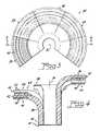
- the light guide 10 acomprises a substantially trumpet-shaped, rigid light transmissive body 12 a having an input widow 14 , a distal end 16 , a front side 18 , and a rear side 20 .
- the light transmissive body 12 ahas a substantially smooth exterior surface on the front side 18 and a substantially clear and solid interior.
- a preferred material for the light guide bodyis a clear plastic.
- the input window 14transmits light received from the LEDs into the light transmissive body 12 a and extends substantially transverse to a longitudinal axis 12 c of the replaceable lamp assembly 10 .
- the light transmissive body 12 ahas a substantially constant thickness measured between the front side 18 and the rear side 20 and extends away from the input window 14 through an arc of from 60 to 120 degrees, with 90° being preferred, to an extension 21 that forms an output region 22 that extends towards the distal end 16 .
- the rear side 20 at least in the output region 22is formed with a plurality of reflective steps 24 using total internal reflection to direct a portion of the intercepted light towards the front side 18 .
- the front side 18 of the output region 22can be formed with refractive features directing light received from the reflective steps 24 in a desired direction.
- the extension 21 of the output region 22comprises about one third of the surface distance from the input window 14 to the distal end 16 while the entire length from the input window 14 to the distal end 16 is more than 10 times the average thickness.
- a difficulty with the trumpet-shaped optic described abovearises when the area beneath the optic, which typically is an automotive fender, comprises a more or less compound curve. It would, therefore, be an advance in the art if a suitable optic could be developed that is simple to construct and capable of matching or accommodating a complex curvature.
- an optical light guidecomprising: a base; a body extending from the base along a longitudinal axis; and N light-emitting segments extending laterally from the body, at least some of the N segments being spaced a different distance from the base.
- the stepped segmentsallow the optic to follow complex curves while still maintaining-acceptable optical efficiency.
- FIG. 1is a plan view of an un-segmented optic
- FIG. 2is a sectional view taken along the line 2 - 2 of FIG. 1 ;
- FIG. 3is a plan view of an embodiment of the invention.
- FIG. 4is a sectional view taken along the line 44 of FIG. 3 ;
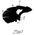
- FIG. 5is a perspective view of an embodiment of an optic of the invention.
- an optical light guide 30comprising: a base 32 ; a body 34 extending from the base along a longitudinal axis 36 ; and N light-emitting segments 38 extending laterally from the body 34 , at least some of the N segments 38 being spaced a different distance from the base 32 .
- the light guide 30is constructed of a light-transmitting material, such as glass or an acrylic, and can be clear or colored.
- each of the segments 38would extend a different distance from the base; however, the exact degree of separation would be dependent upon the curvature of the surface with which the optic is to be utilized.
- the segmentsare all parallel to one another.
- the segments 38extend away from the base 32 through an arc of from 60 to 120 degrees, with 90° being preferred.
- the base 32includes a light input window 40 .
- the input light source associated with the windowwould be supplied by a light emitting diode lamp, such as that shown at 10 in FIG. 2 ; however, other light sources can be employed with the invention
- the N light-emitting segments 38form a section of a circle when viewed transverse to the longitudinal axis 36 ; however, this is exemplary and the actual configuration, as stated above, will depend upon the curvature of the underlying surface with which the optic is being used.
- Each of the segments 38comprises a distal end 42 , a front side 44 and a rear side 46 and these sides can be provided with distinctive optics.
- the rear side 46includes a plurality of triangular steps 48 using total internal reflection to reflect a portion of the light towards the front side.
- the front side 44includes a plurality of refractive features, such as pillow optics 50 . In the interest of clarity only one segment 38 is shown with the pillow optics in FIG. 3 .
Landscapes
- Physics & Mathematics (AREA)
- General Physics & Mathematics (AREA)
- Optics & Photonics (AREA)
- Engineering & Computer Science (AREA)
- General Engineering & Computer Science (AREA)
- Non-Portable Lighting Devices Or Systems Thereof (AREA)
- Lighting Device Outwards From Vehicle And Optical Signal (AREA)
- Illuminated Signs And Luminous Advertising (AREA)
Abstract
Description
Claims (8)
Priority Applications (3)
| Application Number | Priority Date | Filing Date | Title |
|---|---|---|---|
| US11/653,752US7932528B2 (en) | 2005-06-23 | 2007-01-16 | Segmented optic |
| DE112008000179.0TDE112008000179B4 (en) | 2007-01-16 | 2008-01-15 | Segmented optical device |
| PCT/US2008/051033WO2008089162A2 (en) | 2007-01-16 | 2008-01-15 | Segmented optic |
Applications Claiming Priority (4)
| Application Number | Priority Date | Filing Date | Title |
|---|---|---|---|
| US69325405P | 2005-06-23 | 2005-06-23 | |
| US69399905P | 2005-06-24 | 2005-06-24 | |
| US11/447,214US7375382B2 (en) | 2005-06-23 | 2006-06-05 | Direct optical light guide |
| US11/653,752US7932528B2 (en) | 2005-06-23 | 2007-01-16 | Segmented optic |
Related Parent Applications (1)
| Application Number | Title | Priority Date | Filing Date |
|---|---|---|---|
| US11/447,214Continuation-In-PartUS7375382B2 (en) | 2005-06-23 | 2006-06-05 | Direct optical light guide |
Publications (2)
| Publication Number | Publication Date |
|---|---|
| US20070115674A1 US20070115674A1 (en) | 2007-05-24 |
| US7932528B2true US7932528B2 (en) | 2011-04-26 |
Family
ID=39638846
Family Applications (1)
| Application Number | Title | Priority Date | Filing Date |
|---|---|---|---|
| US11/653,752Expired - Fee RelatedUS7932528B2 (en) | 2005-06-23 | 2007-01-16 | Segmented optic |
Country Status (3)
| Country | Link |
|---|---|
| US (1) | US7932528B2 (en) |
| DE (1) | DE112008000179B4 (en) |
| WO (1) | WO2008089162A2 (en) |
Cited By (5)
| Publication number | Priority date | Publication date | Assignee | Title |
|---|---|---|---|---|
| USD813431S1 (en) | 2015-10-16 | 2018-03-20 | Walter R. Tucker Enterprises, Ltd. | Portable light lens |
| US9951930B2 (en) | 2015-10-16 | 2018-04-24 | Walter R. Tucker Enterprises, Ltd. | Portable light |
| USD829354S1 (en) | 2016-12-22 | 2018-09-25 | Walter R. Tucker Enterprises, Ltd. | Portable light |
| USD863632S1 (en) | 2015-10-16 | 2019-10-15 | Walter R. Tucker Enterprises, Ltd. | Portable light lens |
| USD875284S1 (en) | 2015-10-16 | 2020-02-11 | Walter R. Tucker Enterprises, Ltd. | Portable light |
Families Citing this family (8)
| Publication number | Priority date | Publication date | Assignee | Title |
|---|---|---|---|---|
| DE102008021902A1 (en)* | 2008-05-02 | 2009-11-05 | Volkswagen Ag | Lighting device for motor vehicle, has light source i.e. LED, illuminating light, and opening whose diameter extends with increased distance from light source, where opening passes in end section with light injecting surface |
| DE102008021900A1 (en)* | 2008-05-02 | 2009-11-05 | Volkswagen Ag | Lighting device for vehicle, has light input face formed in region of intermediate light disk, and light source, where light emitted from source enters into intermediate light disk and is guided to another region in disk over input face |
| EP2414876B1 (en) | 2009-04-02 | 2017-08-23 | Philips Lighting Holding B.V. | Light emitting device and luminaire |
| USD608938S1 (en) | 2009-09-03 | 2010-01-26 | Osram Sylvania Inc. | Lamp base with translucent light guide |
| TWM415245U (en)* | 2011-06-30 | 2011-11-01 | Chun Kuang Optics Corp | Optic element and lighting device comprising the optic element |
| US8523407B2 (en) | 2011-09-13 | 2013-09-03 | Chun Kuang Optics Corp. | Optical element and illuminant device using the same |
| WO2018029042A1 (en)* | 2016-08-10 | 2018-02-15 | Philips Lighting Holding B.V. | Indirect luminaire |
| DE102017123830A1 (en)* | 2017-10-13 | 2019-04-18 | Dr. Ing. H.C. F. Porsche Aktiengesellschaft | Lighting arrangement for an exterior mirror |
Citations (4)
| Publication number | Priority date | Publication date | Assignee | Title |
|---|---|---|---|---|
| US20030169160A1 (en) | 2000-07-12 | 2003-09-11 | Alejandro Rodriguez Barros | Rear-view mirror with multiple interchangeable signals for vehicles with two, three, four or more wheels |
| US20040264852A1 (en)* | 2003-06-24 | 2004-12-30 | Tai-Ning Tang | Optical fiber light-transmissive structure |
| US20070139946A1 (en) | 2005-12-16 | 2007-06-21 | Ford Global Technologies, Llc | Led unit for a vehicle lamp assembly |
| US7375382B2 (en)* | 2005-06-23 | 2008-05-20 | Osram Sylvania, Inc. | Direct optical light guide |
Family Cites Families (3)
| Publication number | Priority date | Publication date | Assignee | Title |
|---|---|---|---|---|
| EP1005619B1 (en)* | 1997-08-12 | 2001-11-21 | Decoma International Inc. | Bireflective lens element |
| JP2005158362A (en)* | 2003-11-21 | 2005-06-16 | Stanley Electric Co Ltd | Vehicle lighting |
| JP4589168B2 (en)* | 2005-04-13 | 2010-12-01 | 本田技研工業株式会社 | Vehicle lamp structure |
- 2007
- 2007-01-16USUS11/653,752patent/US7932528B2/ennot_activeExpired - Fee Related
- 2008
- 2008-01-15DEDE112008000179.0Tpatent/DE112008000179B4/ennot_activeExpired - Fee Related
- 2008-01-15WOPCT/US2008/051033patent/WO2008089162A2/enactiveApplication Filing
Patent Citations (4)
| Publication number | Priority date | Publication date | Assignee | Title |
|---|---|---|---|---|
| US20030169160A1 (en) | 2000-07-12 | 2003-09-11 | Alejandro Rodriguez Barros | Rear-view mirror with multiple interchangeable signals for vehicles with two, three, four or more wheels |
| US20040264852A1 (en)* | 2003-06-24 | 2004-12-30 | Tai-Ning Tang | Optical fiber light-transmissive structure |
| US7375382B2 (en)* | 2005-06-23 | 2008-05-20 | Osram Sylvania, Inc. | Direct optical light guide |
| US20070139946A1 (en) | 2005-12-16 | 2007-06-21 | Ford Global Technologies, Llc | Led unit for a vehicle lamp assembly |
Cited By (7)
| Publication number | Priority date | Publication date | Assignee | Title |
|---|---|---|---|---|
| USD813431S1 (en) | 2015-10-16 | 2018-03-20 | Walter R. Tucker Enterprises, Ltd. | Portable light lens |
| US9951930B2 (en) | 2015-10-16 | 2018-04-24 | Walter R. Tucker Enterprises, Ltd. | Portable light |
| US10247388B2 (en) | 2015-10-16 | 2019-04-02 | Walter R. Tucker Enterprises, Ltd. | Portable light |
| USD863632S1 (en) | 2015-10-16 | 2019-10-15 | Walter R. Tucker Enterprises, Ltd. | Portable light lens |
| USD866027S1 (en) | 2015-10-16 | 2019-11-05 | Walter R. Tucker Enterprises, Ltd. | Portable light |
| USD875284S1 (en) | 2015-10-16 | 2020-02-11 | Walter R. Tucker Enterprises, Ltd. | Portable light |
| USD829354S1 (en) | 2016-12-22 | 2018-09-25 | Walter R. Tucker Enterprises, Ltd. | Portable light |
Also Published As
| Publication number | Publication date |
|---|---|
| WO2008089162A2 (en) | 2008-07-24 |
| DE112008000179T5 (en) | 2010-01-14 |
| WO2008089162A3 (en) | 2008-10-09 |
| DE112008000179B4 (en) | 2017-12-14 |
| US20070115674A1 (en) | 2007-05-24 |
Similar Documents
| Publication | Publication Date | Title |
|---|---|---|
| US7932528B2 (en) | Segmented optic | |
| US8333493B2 (en) | Dual-direction light pipe for automotive lighting | |
| US6305813B1 (en) | Display device using a light guide for exterior automotive lighting | |
| US7639918B2 (en) | Manifold-type lightguide with reduced thickness | |
| US9689550B2 (en) | Vehicular lamp device | |
| US8992059B2 (en) | Vehicle lighting device with first and second light sources | |
| US20090185389A1 (en) | Light guide for a lamp | |
| US20100014309A1 (en) | Vehicle Light | |
| US20120327680A1 (en) | Reflector signal lamp having a hidden light source | |
| US9581307B2 (en) | Block light module | |
| US20090303731A1 (en) | Light-Transmittable Cover For a Light-Emitting Diode Bulb | |
| CN207080949U (en) | vehicle light guide unit | |
| US20150009696A1 (en) | Lighting device, lighting fitting, and vehicle | |
| US5692827A (en) | Tail lamp for an automotive vehicle using an elongated hyperbolic cylinder | |
| US10823900B2 (en) | Vehicular lamp with elongated light guide portions | |
| US9927087B1 (en) | Fiber optic light panel having a light enhancing element | |
| EP2075500A3 (en) | Vehicle headlamp | |
| US10234615B2 (en) | Illumination device | |
| US9862306B2 (en) | Vehicle decorative lighting device and vehicle lamp | |
| CN113439178A (en) | Light source unit and vehicle lamp | |
| JP6234157B2 (en) | Vehicle lighting | |
| US10119672B2 (en) | Bundle entry weave for lighting modules | |
| JP6785673B2 (en) | Vehicle lighting | |
| CN203010496U (en) | Lamp lens that produces uniform brightness | |
| JP2002274256A (en) | Lighting ring |
Legal Events
| Date | Code | Title | Description |
|---|---|---|---|
| AS | Assignment | Owner name:OSRAM SYLVANIA INC., MASSACHUSETTS Free format text:ASSIGNMENT OF ASSIGNORS INTEREST;ASSIGNOR:TESSNOW, THOMAS;REEL/FRAME:018801/0087 Effective date:20070112 | |
| AS | Assignment | Owner name:OSRAM SYLVANIA INC., MASSACHUSETTS Free format text:MERGER;ASSIGNOR:OSRAM SYLVANIA INC.;REEL/FRAME:025552/0745 Effective date:20100902 | |
| STCF | Information on status: patent grant | Free format text:PATENTED CASE | |
| FEPP | Fee payment procedure | Free format text:PAYOR NUMBER ASSIGNED (ORIGINAL EVENT CODE: ASPN); ENTITY STATUS OF PATENT OWNER: LARGE ENTITY | |
| FPAY | Fee payment | Year of fee payment:4 | |
| MAFP | Maintenance fee payment | Free format text:PAYMENT OF MAINTENANCE FEE, 8TH YEAR, LARGE ENTITY (ORIGINAL EVENT CODE: M1552); ENTITY STATUS OF PATENT OWNER: LARGE ENTITY Year of fee payment:8 | |
| FEPP | Fee payment procedure | Free format text:MAINTENANCE FEE REMINDER MAILED (ORIGINAL EVENT CODE: REM.); ENTITY STATUS OF PATENT OWNER: LARGE ENTITY | |
| LAPS | Lapse for failure to pay maintenance fees | Free format text:PATENT EXPIRED FOR FAILURE TO PAY MAINTENANCE FEES (ORIGINAL EVENT CODE: EXP.); ENTITY STATUS OF PATENT OWNER: LARGE ENTITY | |
| STCH | Information on status: patent discontinuation | Free format text:PATENT EXPIRED DUE TO NONPAYMENT OF MAINTENANCE FEES UNDER 37 CFR 1.362 | |
| FP | Lapsed due to failure to pay maintenance fee | Effective date:20230426 |