US7931859B2 - Ultraviolet sanitization in pharmacy environments - Google Patents
Ultraviolet sanitization in pharmacy environmentsDownload PDFInfo
- Publication number
- US7931859B2 US7931859B2US12/035,850US3585008AUS7931859B2US 7931859 B2US7931859 B2US 7931859B2US 3585008 AUS3585008 AUS 3585008AUS 7931859 B2US7931859 B2US 7931859B2
- Authority
- US
- United States
- Prior art keywords
- radiation
- medical container
- seal assembly
- fluid transfer
- transfer port
- Prior art date
- Legal status (The legal status is an assumption and is not a legal conclusion. Google has not performed a legal analysis and makes no representation as to the accuracy of the status listed.)
- Active, expires
Links
Images


Classifications
- A—HUMAN NECESSITIES
- A61—MEDICAL OR VETERINARY SCIENCE; HYGIENE
- A61L—METHODS OR APPARATUS FOR STERILISING MATERIALS OR OBJECTS IN GENERAL; DISINFECTION, STERILISATION OR DEODORISATION OF AIR; CHEMICAL ASPECTS OF BANDAGES, DRESSINGS, ABSORBENT PADS OR SURGICAL ARTICLES; MATERIALS FOR BANDAGES, DRESSINGS, ABSORBENT PADS OR SURGICAL ARTICLES
- A61L2/00—Methods or apparatus for disinfecting or sterilising materials or objects other than foodstuffs or contact lenses; Accessories therefor
- A61L2/02—Methods or apparatus for disinfecting or sterilising materials or objects other than foodstuffs or contact lenses; Accessories therefor using physical phenomena
- A61L2/08—Radiation
- A61L2/10—Ultraviolet radiation
- A—HUMAN NECESSITIES
- A61—MEDICAL OR VETERINARY SCIENCE; HYGIENE
- A61J—CONTAINERS SPECIALLY ADAPTED FOR MEDICAL OR PHARMACEUTICAL PURPOSES; DEVICES OR METHODS SPECIALLY ADAPTED FOR BRINGING PHARMACEUTICAL PRODUCTS INTO PARTICULAR PHYSICAL OR ADMINISTERING FORMS; DEVICES FOR ADMINISTERING FOOD OR MEDICINES ORALLY; BABY COMFORTERS; DEVICES FOR RECEIVING SPITTLE
- A61J1/00—Containers specially adapted for medical or pharmaceutical purposes
- A61J1/14—Details; Accessories therefor
- A61J1/20—Arrangements for transferring or mixing fluids, e.g. from vial to syringe
- A—HUMAN NECESSITIES
- A61—MEDICAL OR VETERINARY SCIENCE; HYGIENE
- A61J—CONTAINERS SPECIALLY ADAPTED FOR MEDICAL OR PHARMACEUTICAL PURPOSES; DEVICES OR METHODS SPECIALLY ADAPTED FOR BRINGING PHARMACEUTICAL PRODUCTS INTO PARTICULAR PHYSICAL OR ADMINISTERING FORMS; DEVICES FOR ADMINISTERING FOOD OR MEDICINES ORALLY; BABY COMFORTERS; DEVICES FOR RECEIVING SPITTLE
- A61J3/00—Devices or methods specially adapted for bringing pharmaceutical products into particular physical or administering forms
- A61J3/002—Compounding apparatus specially for enteral or parenteral nutritive solutions
- B—PERFORMING OPERATIONS; TRANSPORTING
- B01—PHYSICAL OR CHEMICAL PROCESSES OR APPARATUS IN GENERAL
- B01F—MIXING, e.g. DISSOLVING, EMULSIFYING OR DISPERSING
- B01F33/00—Other mixers; Mixing plants; Combinations of mixers
- B01F33/80—Mixing plants; Combinations of mixers
- B01F33/85—Mixing plants with mixing receptacles or mixing tools that can be indexed into different working positions
- B—PERFORMING OPERATIONS; TRANSPORTING
- B65—CONVEYING; PACKING; STORING; HANDLING THIN OR FILAMENTARY MATERIAL
- B65B—MACHINES, APPARATUS OR DEVICES FOR, OR METHODS OF, PACKAGING ARTICLES OR MATERIALS; UNPACKING
- B65B3/00—Packaging plastic material, semiliquids, liquids or mixed solids and liquids, in individual containers or receptacles, e.g. bags, sacks, boxes, cartons, cans, or jars
- B65B3/003—Filling medical containers such as ampoules, vials, syringes or the like
- B—PERFORMING OPERATIONS; TRANSPORTING
- B65—CONVEYING; PACKING; STORING; HANDLING THIN OR FILAMENTARY MATERIAL
- B65B—MACHINES, APPARATUS OR DEVICES FOR, OR METHODS OF, PACKAGING ARTICLES OR MATERIALS; UNPACKING
- B65B55/00—Preserving, protecting or purifying packages or package contents in association with packaging
- B65B55/02—Sterilising, e.g. of complete packages
- B65B55/04—Sterilising wrappers or receptacles prior to, or during, packaging
- B65B55/08—Sterilising wrappers or receptacles prior to, or during, packaging by irradiation
- G—PHYSICS
- G07—CHECKING-DEVICES
- G07F—COIN-FREED OR LIKE APPARATUS
- G07F11/00—Coin-freed apparatus for dispensing, or the like, discrete articles
- G07F11/02—Coin-freed apparatus for dispensing, or the like, discrete articles from non-movable magazines
- G07F11/04—Coin-freed apparatus for dispensing, or the like, discrete articles from non-movable magazines in which magazines the articles are stored one vertically above the other
- G07F11/16—Delivery means
- G07F11/165—Delivery means using xyz-picker or multi-dimensional article picking arrangements
- G07F11/1657—Delivery means using xyz-picker or multi-dimensional article picking arrangements the picking arrangements using suction
- G—PHYSICS
- G07—CHECKING-DEVICES
- G07F—COIN-FREED OR LIKE APPARATUS
- G07F11/00—Coin-freed apparatus for dispensing, or the like, discrete articles
- G07F11/02—Coin-freed apparatus for dispensing, or the like, discrete articles from non-movable magazines
- G07F11/44—Coin-freed apparatus for dispensing, or the like, discrete articles from non-movable magazines in which magazines the articles are stored in bulk
- G—PHYSICS
- G07—CHECKING-DEVICES
- G07F—COIN-FREED OR LIKE APPARATUS
- G07F11/00—Coin-freed apparatus for dispensing, or the like, discrete articles
- G07F11/46—Coin-freed apparatus for dispensing, or the like, discrete articles from movable storage containers or supports
- G07F11/48—Coin-freed apparatus for dispensing, or the like, discrete articles from movable storage containers or supports the storage containers or supports, e.g. magazine, being pivotally mounted
- G—PHYSICS
- G07—CHECKING-DEVICES
- G07F—COIN-FREED OR LIKE APPARATUS
- G07F11/00—Coin-freed apparatus for dispensing, or the like, discrete articles
- G07F11/46—Coin-freed apparatus for dispensing, or the like, discrete articles from movable storage containers or supports
- G07F11/50—Coin-freed apparatus for dispensing, or the like, discrete articles from movable storage containers or supports the storage containers or supports being rotatably mounted
- G07F11/54—Coin-freed apparatus for dispensing, or the like, discrete articles from movable storage containers or supports the storage containers or supports being rotatably mounted about vertical axes
- G—PHYSICS
- G07—CHECKING-DEVICES
- G07F—COIN-FREED OR LIKE APPARATUS
- G07F11/00—Coin-freed apparatus for dispensing, or the like, discrete articles
- G07F11/62—Coin-freed apparatus for dispensing, or the like, discrete articles in which the articles are stored in compartments in fixed receptacles
- G—PHYSICS
- G07—CHECKING-DEVICES
- G07F—COIN-FREED OR LIKE APPARATUS
- G07F17/00—Coin-freed apparatus for hiring articles; Coin-freed facilities or services
- G07F17/0092—Coin-freed apparatus for hiring articles; Coin-freed facilities or services for assembling and dispensing of pharmaceutical articles
- G—PHYSICS
- G07—CHECKING-DEVICES
- G07F—COIN-FREED OR LIKE APPARATUS
- G07F9/00—Details other than those peculiar to special kinds or types of apparatus
- G07F9/10—Casings or parts thereof, e.g. with means for heating or cooling
- A—HUMAN NECESSITIES
- A61—MEDICAL OR VETERINARY SCIENCE; HYGIENE
- A61J—CONTAINERS SPECIALLY ADAPTED FOR MEDICAL OR PHARMACEUTICAL PURPOSES; DEVICES OR METHODS SPECIALLY ADAPTED FOR BRINGING PHARMACEUTICAL PRODUCTS INTO PARTICULAR PHYSICAL OR ADMINISTERING FORMS; DEVICES FOR ADMINISTERING FOOD OR MEDICINES ORALLY; BABY COMFORTERS; DEVICES FOR RECEIVING SPITTLE
- A61J2200/00—General characteristics or adaptations
- A61J2200/70—Device provided with specific sensor or indicating means
- A61J2200/74—Device provided with specific sensor or indicating means for weight
- A—HUMAN NECESSITIES
- A61—MEDICAL OR VETERINARY SCIENCE; HYGIENE
- A61J—CONTAINERS SPECIALLY ADAPTED FOR MEDICAL OR PHARMACEUTICAL PURPOSES; DEVICES OR METHODS SPECIALLY ADAPTED FOR BRINGING PHARMACEUTICAL PRODUCTS INTO PARTICULAR PHYSICAL OR ADMINISTERING FORMS; DEVICES FOR ADMINISTERING FOOD OR MEDICINES ORALLY; BABY COMFORTERS; DEVICES FOR RECEIVING SPITTLE
- A61J2205/00—General identification or selection means
- A61J2205/10—Bar codes
- A—HUMAN NECESSITIES
- A61—MEDICAL OR VETERINARY SCIENCE; HYGIENE
- A61J—CONTAINERS SPECIALLY ADAPTED FOR MEDICAL OR PHARMACEUTICAL PURPOSES; DEVICES OR METHODS SPECIALLY ADAPTED FOR BRINGING PHARMACEUTICAL PRODUCTS INTO PARTICULAR PHYSICAL OR ADMINISTERING FORMS; DEVICES FOR ADMINISTERING FOOD OR MEDICINES ORALLY; BABY COMFORTERS; DEVICES FOR RECEIVING SPITTLE
- A61J2205/00—General identification or selection means
- A61J2205/30—Printed labels
- A—HUMAN NECESSITIES
- A61—MEDICAL OR VETERINARY SCIENCE; HYGIENE
- A61J—CONTAINERS SPECIALLY ADAPTED FOR MEDICAL OR PHARMACEUTICAL PURPOSES; DEVICES OR METHODS SPECIALLY ADAPTED FOR BRINGING PHARMACEUTICAL PRODUCTS INTO PARTICULAR PHYSICAL OR ADMINISTERING FORMS; DEVICES FOR ADMINISTERING FOOD OR MEDICINES ORALLY; BABY COMFORTERS; DEVICES FOR RECEIVING SPITTLE
- A61J2205/00—General identification or selection means
- A61J2205/60—General identification or selection means using magnetic or electronic identifications, e.g. chips, RFID, electronic tags
- G—PHYSICS
- G16—INFORMATION AND COMMUNICATION TECHNOLOGY [ICT] SPECIALLY ADAPTED FOR SPECIFIC APPLICATION FIELDS
- G16H—HEALTHCARE INFORMATICS, i.e. INFORMATION AND COMMUNICATION TECHNOLOGY [ICT] SPECIALLY ADAPTED FOR THE HANDLING OR PROCESSING OF MEDICAL OR HEALTHCARE DATA
- G16H20/00—ICT specially adapted for therapies or health-improving plans, e.g. for handling prescriptions, for steering therapy or for monitoring patient compliance
- G16H20/10—ICT specially adapted for therapies or health-improving plans, e.g. for handling prescriptions, for steering therapy or for monitoring patient compliance relating to drugs or medications, e.g. for ensuring correct administration to patients
- G16H20/13—ICT specially adapted for therapies or health-improving plans, e.g. for handling prescriptions, for steering therapy or for monitoring patient compliance relating to drugs or medications, e.g. for ensuring correct administration to patients delivered from dispensers
- G—PHYSICS
- G16—INFORMATION AND COMMUNICATION TECHNOLOGY [ICT] SPECIALLY ADAPTED FOR SPECIFIC APPLICATION FIELDS
- G16H—HEALTHCARE INFORMATICS, i.e. INFORMATION AND COMMUNICATION TECHNOLOGY [ICT] SPECIALLY ADAPTED FOR THE HANDLING OR PROCESSING OF MEDICAL OR HEALTHCARE DATA
- G16H20/00—ICT specially adapted for therapies or health-improving plans, e.g. for handling prescriptions, for steering therapy or for monitoring patient compliance
- G16H20/10—ICT specially adapted for therapies or health-improving plans, e.g. for handling prescriptions, for steering therapy or for monitoring patient compliance relating to drugs or medications, e.g. for ensuring correct administration to patients
- G16H20/17—ICT specially adapted for therapies or health-improving plans, e.g. for handling prescriptions, for steering therapy or for monitoring patient compliance relating to drugs or medications, e.g. for ensuring correct administration to patients delivered via infusion or injection
- Y—GENERAL TAGGING OF NEW TECHNOLOGICAL DEVELOPMENTS; GENERAL TAGGING OF CROSS-SECTIONAL TECHNOLOGIES SPANNING OVER SEVERAL SECTIONS OF THE IPC; TECHNICAL SUBJECTS COVERED BY FORMER USPC CROSS-REFERENCE ART COLLECTIONS [XRACs] AND DIGESTS
- Y10—TECHNICAL SUBJECTS COVERED BY FORMER USPC
- Y10S—TECHNICAL SUBJECTS COVERED BY FORMER USPC CROSS-REFERENCE ART COLLECTIONS [XRACs] AND DIGESTS
- Y10S604/00—Surgery
- Y10S604/905—Aseptic connectors or couplings, e.g. frangible, piercable
Definitions
- Various embodimentsrelate to handling medical containers such as syringes, vials, and IV bags.
- IV bagsintravenous bags into which a quantity of a medication is introduced.
- the medicationmay be an admixture with a diluent.
- the IV bagcontains only the medication and diluent.
- the IV bagmay also contain a carrier or other material to be infused into the patient simultaneously with the medication.
- Medicationcan also be delivered to a patient using a syringe.
- Medicationis often supplied, for example, in powder form in a medication container or in a vial.
- a diluent liquidmay be supplied for making an admixture with the medication in a separate or diluent container or vial.
- a pharmacistmay mix a certain amount of medication (e.g., which may be in dry form such as a powder) with a particular amount of a diluent according to a prescription. The admixture may then be delivered to a patient.
- One function of the pharmacistis to prepare a dispensing container, such as an IV bag or a syringe, that contains a proper amount of diluent and medication according to the prescription for that patient.
- a dispensing containersuch as an IV bag or a syringe
- Some prescriptionse.g., insulin
- a number of similar IV bags containing similar medicationcan be prepared in a batch, although volumes of each dose may vary, for example.
- Other prescriptions, such as those involving chemotherapy drugsmay require very accurate and careful control of diluent and medication to satisfy a prescription that is tailored to the needs of an individual patient.
- the preparation of a prescription in a syringe or an IV bagmay involve, for example, transferring fluids, such as medication or diluent, among vials, syringes, and/or IV bags.
- IV bagsare typically flexible, and may readily change shape as the volume of fluid they contain changes.
- IV bags, vials, and syringesare commercially available in a range of sizes, shapes, and designs.
- Systems and methods to reduce bioburden on at least a portion of a fluid transfer portinclude supplying a dose of radiation to the fluid transfer port that is in optical communication with at least one source of radiation.
- a medical containersuch as a vial or IV bag, receives a dose of ultraviolet (UV) energy substantially at a predetermined region of a fluid transfer site.
- UVultraviolet
- a sanitization processmay precede a fluid transfer operation in which a fluid is transferred into or out of the medical container by passing through the sanitized region.
- Such fluid transfersmay be used in automated or semi-automated pharmaceutical processes, such as drug reconstitution.
- Various embodimentsmay further include one or more seal assemblies, each seal assembly having an aperture through which the radiation dose is supplied from the source to a controlled region on the fluid transfer port.
- an Automated Pharmacy Admixture Systemmay include an automated system to transport medical containers such as bags, vials, or syringes in a compounding chamber that may be regulated to a pressure above or below atmospheric pressure.
- the automated transportation systemis configured to grasp and convey syringes, IV bags, and vials of varying shapes and sizes from a storage system in an adjacent chamber that may be regulated at a pressure above or below atmospheric pressure.
- Various embodimentsmay include a controller adapted to actuate the automated transportation system to bring a fill port of an IV bag, vial, or syringe into register with a filling port at a fluid transfer station in the chamber.
- One implementationincludes a sanitization system that can substantially sanitize a bung on a fill port of a vial or IV bag in preparation for transport to the fluid transfer station.
- a port sanitization systemmay be used in the sanitization of vial and bag ports in an IV admixture compounding application.
- the PSS systemmay be a stand-alone or table top system, or may be adapted for integration into an APAS cell.
- the PSSmay include one or more radiation (e.g., UV) sources; one or more mechanisms for holding a medical container (e.g., drug vial, IV bag and syringe); one or more mechanisms for radiation sealing or containment; one or more cooling, purging and/or venting systems; a control and monitoring system; and interlocks and/or safety mechanisms.
- radiatione.g., UV
- a medical containere.g., drug vial, IV bag and syringe
- mechanisms for radiation sealing or containmente.g., drug vial, IV bag and syringe
- cooling, purging and/or venting systemse.g., purging and/or venting systems
- control and monitoring systeme.g., a control and monitoring system
- the PSSmay utilize a single centralized UV source or multiple distributed UV sources.
- the UV source(s)can deliver UV radiation in a pulsed and/or constant wave form and by continuous emission, intermittent emission or pulsed emission.
- the UV source(s)can deliver a predetermined dose in a fixed or variable profile based on the target biocontaminant(s).
- at least one optical conduite.g., light pipe, optical fiber, and optical waveguide
- the PSSmay include one or more aperture assembly for sealing or containing the UV radiation.
- the sealing assemblycan be designed such that in operation the sealing assembly does not touch the area(s) to be sanitized.
- the sealing aperture assemblyincludes at least one baffle that is configured to form one or more apertures.
- the sealing aperture assemblyincludes a gasket that is formed around an aperture.
- a pressure chambermay be used to engage a medical container with the sealing assembly by substantially forming a light seal between them.
- the sealing aperture assemblyincludes a concave receptacle with an aperture.
- multiple sealing aperture assembliesare used to cover medical containers with different shapes and sizes.
- the PSSmay incorporate a controller that can determine which radiation seal assembly should be used based on the size and/or shape of the medical container to be sanitized.
- the PSSmay also include an actuator that can move various components (e.g., the medical container, the apparatus for holding the medical container, the radiation sealing assembly, and the UV source) either individually or in concert to bring the portion of the fluid transfer port to be sanitized into optical communication with the UV source through the aperture of the radiation seal assembly.
- various componentse.g., the medical container, the apparatus for holding the medical container, the radiation sealing assembly, and the UV source
- the APASmay compound toxic and/or volatile substances, such as those used for chemotherapy, in a substantially aseptic chamber at pressure below ambient pressure to substantially avoid unintentional escape of the substances outside of the chamber.
- the APASmay be programmed to select medical containers, such as IV bags, syringes, and/or vials, according to site-specific (e.g., hospital) protocols for containers for particular drug orders.
- medical items, including IV bag and vial bung portsmay be positioned to receive a sanitizing dose of ultraviolet, which can effectively decrease bioburden (e.g., viruses, bacteria, mold, etc.).
- Further advantagesmay include reduction or elimination of sanitizing consumables, and a significantly reduced risk of explosive fumes (in the enclosed cell context) associated with some consumable sanitizers.
- FIG. 1shows an illustrative Automated Pharmacy Admixture System (APAS) cell.
- APASAutomated Pharmacy Admixture System
- FIG. 2shows a top cut-away view of the APAS cell of FIG. 1 .
- FIGS. 3A-3Cshow cross-sectional views of an illustrative port sanitization system (PSS).
- PSSport sanitization system
- FIGS. 4A-4Cshow cross-sectional views of an illustrative PSS that accepts variously sized objects to be sanitized in an APAS cell.
- FIG. 5shows an illustrative enclosed PSS.
- FIG. 6shows an exemplary PSS without surrounding walls.
- FIG. 7shows an illustrative PSS with gripper mechanism.
- FIGS. 8A and 8Bshows an exemplary IV bag and drug vial sanitization, respectively.
- FIGS. 9A and 9Bshow a top view and an isoparametric view of an exemplary cleaner carousel, respectively.
- FIG. 10is a block diagram of an exemplary control module for the PSS of FIGS. 3A-3C .
- FIGS. 11A-11Fshow cross-sectional views of an illustrative PSS in an APAS cell.
- FIG. 12shows an exemplary apparatus for performing a fluid transfer operation.
- An Automated Pharmacy Admixture Systemmay include a manipulator that transports medical containers such as bags, vials, or syringes about a substantially aseptic admixing chamber.
- the chamberincludes a number of processing stations at which the medical containers can be processed to perform reconstitution for prescription medication doses.
- processing stationsmay include apparatus to substantially sanitize, disinfect, and/or sterilize portions of the medical containers prior to performing a fluid transfer operation.
- a gripper assemblyis configured to substantially universally grasp and retain syringes, IV bags, and vials of varying shapes and sizes.
- a gripping devicemay include claws configured to grasp a plurality of different types of IV bags, each type having a different fill port configuration.
- Embodimentsmay include a controller adapted to actuate a transport assembly to place a fill port of the bag, vial or syringe into register with a filling port such as a cannula located at a filling station, or be equipped with carousel transport systems that are adapted to convey bags, vials, and syringes to the admixture system and deliver constituted medications in bags, vials or syringes to an egress area.
- a controlleradapted to actuate a transport assembly to place a fill port of the bag, vial or syringe into register with a filling port such as a cannula located at a filling station, or be equipped with carousel transport systems that are adapted to convey bags, vials, and syringes to the admixture system and deliver constituted medications in bags, vials or syringes to an egress area.
- FIG. 1shows an illustrative Automated Pharmacy Admixture System (APAS) cell device 100 for use within a hospital pharmacy environment.
- the APAS cell 100may autonomously admix contents of syringes and IV bags using automation technologies.
- embodiments of the APAS cell 100may perform one or more operations that might otherwise be performed by pharmacy staff within a laminar airflow hood.
- the APAS cell 100includes a robotic cell that automates the compounding and dispensing of drug doses into IV bags and/or syringes, such as those that may be prepared in hospital pharmacies.
- the robotic cellmay use a syringe-based fluid transfer process, and may employ a robotic manipulator (e.g., a multiple degree of freedom arm) for moving drug vials, syringes, and IV bags through the cell as the medications are processed.
- a robotic manipulatore.g., a multiple degree of freedom arm
- FIG. 2shows an illustrative top cut-away view of the APAS cell of FIG. 1 .
- the APAS cell 100includes two chambers.
- An inventory chamber 202is used as an inventory loading area, which can be accessed by an operator to load the APAS cell 100 through a loading door (not shown).
- the inventory chamber 202provides a substantially aseptic environment, which may be an ISO Class 5 environment that complies with clean room standards.
- a processing chamber 204includes the compounding area in which the admixture and/or compounding processes may occur.
- the processing chamber 204provides a substantially aseptic environment, which may be an ISO Class 5 environment that complies with clean room standards.
- Mounted on the exterior of the APAS cell 100are two of the monitors 102 , which may serve as input/output devices.
- the inventory chamber 202includes two inventory rack carousels 210 and 212 and a temporary inventory rack 214 .
- the temporary inventory rack 214may be used to locate in-process drug vials that contain enough material to provide multiple doses.
- Each inventory rack carousel 210 or 212may support multiple inventory racks (not shown).
- an operatormay remove one or more racks from the carousels 210 , 212 and replace them with racks loaded with inventory.
- the racksmay be loaded onto the carousels 210 , 212 according to a load map, which may be generated by the operator for submission to the APAS cell 100 , or generated by the APAS cell 100 and communicated to the operator.
- the chambers 202 , 204are substantially separated by a dividing wall 216 .
- the processing chamber 204includes a multiple degree of freedom robotic arm 218 , and the robotic arm 218 further includes a gripper that can be used, for example, to pick items from a pocket on a rack or to grasp items within the APAS cell 100 for manipulation.
- the robotic arm 218may respond to command signals from a controller (not shown) to pick up, manipulate, or reposition inventory items within the processing chamber 204 , and in or around the carousels 210 , 212 .
- the robotic arm 218may manipulate inventory items, for example, by picking a vial, IV bag, or syringe from a rack of the carousels 210 , 212 in the inventory chamber 202 , and moving the item to a station in the processing chamber 204 for use in compound preparation.
- the robotic arm 218may manipulate inventory items on the carousels 210 , 212 through access port (not shown) in the dividing wall 216 .
- the dividing wall 216may be substantially sealed so that a substantially aseptic environment may be maintained for compounding processes in the processing chamber 204 .
- an incoming drug order from a remote user stationinvolves a batch production order for syringes to be charged with individual doses of a drug that is reconstituted from a drug provided in one or more vials.
- the operatormay preload the drug into the APAS cell 100 during a loading process by loading the carousel 210 with inventory racks of the drug vials, and by interfacing with the APAS cell 100 using the input/output device 102 to initiate, monitor, and/or control the loading process.
- the operatormay load the carousel 212 with inventory racks of syringes, drug vials, and IV bags for the next batch production order while the APAS cell 100 is operating the carousel 210 .
- the operatormay submit the batch production process, which may begin immediately, or after other processing is completed.
- the robotic arm 218may pick a syringe from a pocket in a rack in carousel 210 .
- the syringe in the carouselmay have a needle and a needle cap.
- the needle capis removed for processing in the APAS cell 100 .
- the robotic arm 218may convey the syringe to a decapper/deneedler station 220 where the needle cap is removed from the syringe/needle assembly to expose the needle.
- the robotic arm 218moves the syringe to a scale station 226 where the syringe is weighed to determine its empty weight.
- the robotic arm 218may transfer the syringe to a needle-up syringe manipulator 222 where a dose of the drug is drawn from a vial, which was previously placed there by the robotic arm 218 after one or more verification operations (e.g. weighing, bar code scanning, and/or machine vision recognition techniques).
- the robotic arm 218moves the syringe to the decapper/deneedler station 220 where the needle is removed from the syringe and disposed of into a sharps container (not shown).
- the robotic arm 218then moves the syringe to a syringe capper station 224 , where the needleless syringe is capped.
- the robotic arm 218moves the syringe to a scale station 226 where the syringe is weighed to confirm the predetermined dose programmed into the APAS cell.
- the robotic arm 218then moves the syringe to a printer and labeling station 228 to receive a computer readable identification (ID) label that is printed and applied to the syringe.
- IDcomputer readable identification
- This labelmay have a bar code or other computer readable code printed on it which may contain, for example, patient information, the name of the drug in the syringe, the amount of the dose, as well as date and/or lot code information for the inputs.
- the robotic arm 218then moves the syringe to an output scanner station 230 where the information on the ID label is read by the scanner to verify that the label is readable.
- the APAS cell 100may report back to the remote user station using a local communication network, for use in operations planning.
- the syringeis then taken by the robotic arm 218 and dropped into the syringe discharge chute 232 where it is available to the pharmacy technician, for example, to be placed in inventory within the hospital pharmacy.
- there may be times during the drug order processwhere the robotic arm 218 removes an empty vial from the needle-up syringe manipulator 222 and places it into a waste chute 233 .
- a syringemay be used both as an input containing a fluid (e.g., diluent or known drug compound) to be admixed in a compounding process, and as an output containing a prepared dose suitable for delivery to a patient.
- a fluide.g., diluent or known drug compound
- Such a syringemay be needed to fulfill a special reconstitution order programmed into the APAS cell 100 via the input/output capabilities of the monitor 102 , for example.
- the ordermay be a stat order, which may be received from a hospital interface.
- the operatorperforms in situ loading by placing the syringes to be used for both reconstitution and dosing in pockets on a rack already located on the carousel 210 .
- the operatorenters the reconstitution order into the APAS cell 100 .
- the robotic arm 218picks the selected syringe from a pocket in the rack in the carousel 210 and moves it to the decapper/deneedler station 220 , where the needle cap is removed from the syringe/needle combination, thereby exposing the needle.
- the syringeis then transferred by the robotic arm 218 to a needle-down syringe manipulator 234 .
- diluentis drawn into the syringe from a diluent supply IV bag 236 previously placed there by the robotic arm 218 .
- the diluent supply 236may be contained in an IV bag which is hung on the needle-down syringe manipulator 234 by a clip (not shown).
- An air extraction processmay be performed to prime the IV bag, if needed.
- the syringethen punctures the membrane of the diluent port 238 in a needle-down orientation.
- the syringeis actuated to remove, for example, a predetermined amount of the diluent from the IV bag.
- the needle-down syringe manipulator 234then moves a reconstitution vial 250 , placed there previously by the robotic arm 218 , under the syringe.
- the diluent in the syringeis transferred to the vial for reconstitution with the vial contents.
- the robotic arm 218then moves the vial to a mixer 248 for shaking according to a mixing profile.
- the robotic arm 218then moves the vial to the needle-up syringe manipulator 222 where the appropriate amount of the reconstituted drug is drawn from the vial into an “output” syringe that was previously conveyed there by the robotic arm 218 .
- the APAS cell 100may receive a production order to prepare compounds that may involve IV bags as input inventory items or as outputs.
- an IV bagmay be selected as a diluent source for reconstitution in a drug order to be output into another medical container.
- the selected IV bagmay be used for output after preparation of the drug order is completed.
- Some IV bagsmay be placed on the carousels 210 , 212 and used as an input that may be at least partially filled with a diluent that may be used to reconstitute drugs.
- the reconstituted drugsmay be output in the form of charged syringes or IV bags. The operator loads racks of syringes and IV bags into the carousel 210 for use in the production order.
- the robotic arm 218picks an IV bag from a rack on the carousel 210 and moves it to the scale and bag ID station 226 .
- the IV bagis identified by bar code or pattern matching and its weight is recorded. This may be done, for example, as an error check, and/or to positively identify the type and/or volume of diluent being used for reconstitution. If the IV bag is selected as a diluent source, then the bag may be weighed before use to confirm the presence of the diluent in the IV bag. If the IV bag is selected for output, it may be weighed multiple times, such as before, during, and/or after each fluid transfer step, for example.
- the weightmay be re-checked after fluid transfer operations have occurred to determine if the change in weight is within an expected range. Such checks may detect, for example, leaks, spills, overfills, or material input errors.
- the robotic arm 218moves the IV bag to a port cleaner station 240 where a ultraviolet (UV) light or other sanitizing process may be used to substantially sterilize, disinfect or sanitize at least a portion of the IV bag port.
- the robotic arm 218moves the IV bag to the needle-up syringe manipulator 222 where a pre-filled syringe has been loaded.
- the IV bagmay be inverted so that the fill port is oriented downwardly for the fill process.
- the contents of the syringemay then be injected into the IV bag.
- the robotic arm 218then conveys the IV bag to the scale station 226 where the IV bag is weighed to confirm the predetermined dose programmed into the APAS cell 100 .
- the robotic arm 218then moves the IV bag to a bag labeler tray station 242 where a label printed by the printer and labeling station 228 is applied to the IV bag.
- the robotic arm 218may move the IV bag to the output scanner station 230 , where the information on the ID label is read by the scanner to verify that the label is readable. One or more further verification checks may be performed.
- the IV bagis then taken by the robotic arm 218 and dropped into the IV bag discharge chute 244 where it is available to the pharmacy technician, for example, to be placed in inventory within the hospital pharmacy.
- a vial(or other medical item or container) may be prepared for reconstitution.
- the vialmay be identified at a vial ID station where, for example, a bar coded label on the vial may be read by a scanner and/or image hardware in combination with image processing software. The captured information may be processed to identify the contents of the vial and correlate it to what is expected.
- the APAS cell 100may employ pattern matching on the vial using optical scanning techniques.
- vial mixers 248may be used to mix the vial contents with the diluent before using it for dosing.
- the robotic manipulatormay include apparatus for reading machine readable indicia in the APAS, including the compounding chamber and/or the storage chamber.
- the manipulatormay include a fiber optic camera for taking images that can be processed to compare to stored image information (e.g., bitmaps).
- the reading apparatusmay include optical scanning (e.g., bar code) or RFID (radio frequency identification).
- Some embodimentsmay transmit image information wirelessly (e.g., using infrared or RF (radio frequency) transmissions) to a receiver coupled to the APAS.
- a receivermay be located inside or outside the chamber with the robotic manipulator.
- Such a readermay be used to read machine readable indicia at various locations in and around the compounding chamber, including through windows and on portions of the storage carousels that are exposed to the compounding chamber.
- a UV port sanitization systemis used in the sanitization of vial and bag ports in an IV admixture compounding application.
- Variants of the system described heremay also include sanitization of syringe bodies.
- the systemmay be part of an APAS cell or used as a stand alone device. Examples of an APAS system are described in further detail, for example, in U.S. patent application Ser. No. 11/316,795, entitled “Automated Pharmacy Admixture System,” and filed on Dec. 22, 2005, and U.S. patent application Ser. No. 11/389,995, entitled “Automated Pharmacy Admixture System,” and filed on Mar. 27, 2006, the contents of each of which are incorporated herein by reference.
- operations to sanitize an objectmay refer to operations to reduce the bioburden on the object to be sanitized.
- a sanitizing operationmay be intended to reduce active (e.g., living) bioburden to some degree.
- the disclosed sanitization of an objectmay substantially disinfect at least a portion of the object.
- the disclosed sanitization of an objectmay substantially sterilize at least a portion of the object. Exemplary desired bioburden inactivation is greater than or equal to a 6 log reduction, but could vary slightly from this, depending on the target organism.
- At least 99.9999%, 99.99%, 99%, 95%, 90%, 80%, 75%, 70%, 60%, or at least about 50% of a particular biocontaminantmay be killed or incapacitated. In some embodiments, between about 1 and 100% of a particular biocontaminant may be inactivated.
- the mechanism of sanitizing the target objectmay be through the exposure of ultraviolet radiation.
- This exposuremay be delivered in, among other methods, a pulsed and/or constant wave form.
- the dose of ultraviolet radiationmay include one or more pulses.
- the dosemay include a timed exposure at a controlled intensity.
- the intensitymay be controlled by modulation of current and/or voltage applied to the radiation source to substantially achieve the controlled radiation level, which may increase, decrease, and/or remain substantially constant during the dose time period.
- a controllermay achieve time-varying or constant radiation level by modulation of optical path's transmission characteristics, such as by selecting which of a number of optical paths to use to couple the radiation from the source to the target region on the fill port, and/or by modulating characteristics of the optical coupling (e.g., filtering) to couple more or less radiation from the source to the target.
- the radiation subjected to the targetis known as the delivered dose.
- the doseincludes an accumulated exposure value.
- a desired doseis one that is predetermined based on, for example, a desired accumulated exposure value at a specific energy density selected to be sufficient to inactivate one or more types of biocontaminants to a selected degree.
- sanitizationmay involve, for example, reducing the number of viable microorganisms present in a sample.
- Biocontaminantsmay include, but are not limited to, viruses, bacteria, molds, protozoa and yeasts, for example.
- ultraviolet radiationmay be used to kill one or more types of the biocontaminants on, around, or within portions of an I.V. bag, syringe and/or vial, such as around the fill port of such I.V. bag, syringe and/or vial.
- such bioburdenmay be found in environments such as medical clinics, hospitals, hospital pharmacies, research laboratories, or other facilities in which pharmaceuticals may be packaged, prepared, stored, transported, or otherwise handled.
- Some embodimentsmay be beneficially applied to provide or enhance sanitization of vials, syringes, packaging (e.g., I.V. bags), tubing, access ports, and/or associated equipment (e.g., handling equipment, including robotic manipulators), fluids (e.g., water), or other materials that may come into proximity and/or contact with objects for which sanitization may be a concern.
- packaginge.g., I.V. bags
- tubinge.g., access ports, and/or associated equipment
- associated equipmente.g., handling equipment, including robotic manipulators
- fluidse.g., water
- Some applicationsmay relate to the preparation of pharmaceutical and/or medical devices, such as delivery systems for providing parental nutrition or insulin to patients, for example.
- the UV port sanitization systemmay include one or more of the following components: one or more UV sources; one or more vial, syringe, and/or bag port holding systems or methods; one or more systems or methods for appropriate sealing or containment of UV for both drug/fluid and/or user protection; one or more cooling, purging and/or venting systems; a control and monitoring system; and interlocks and/or safety mechanisms.
- some embodiments of the PSSmay include a single centralized UV source with selectable masks or apertures for the variety of vials and bags. Some embodiments may also utilize multiple distributed sources that can be conveniently located (e.g., for replacement, maintenance), or combined with other subsystems or functions in the APAS cell context.
- the amount of UV time exposure required for sanitizationis a function of the energy level received by the target at the required frequency spectrum.
- a predetermined exposure time for a dosemay be based on other criteria.
- Both fixed and variable profilesmay be executed at various levels of intensity, number, spacing, and timing.
- the PSSmay include apparatus to focus or direct radiation supplied from each of the UV sources onto one or more selected regions or spots, or combine their output patterns using offsets to provide the desired illumination pattern at the fill port of a target.
- UV sourcesmay have non-uniform output patterns. By changing pattern centerlines, an aggregate output energy pattern that meets desired requirements can be generated.
- One exampleis to have 3 UV sources combined in such a manner as to provide a nearly uniform energy output over a much wider range than could be achieved with focusing the 3 UV sources onto a single spot.
- a UV sourcemay include, for example, flash bulbs to produce very high peak energy levels, on the order of 1 J/cm 2 , or 10 J/cm 2 , or 30 J/cm 2 in the UV-C band, which may include, but are not limited to, between 100 nm and 280 nm. In some examples, these are provided in very short bursts ranging from less than 1 ns to 100 ms at frequencies from about 0.01 Hz to about 1 kHz. Some pulsed bulbs may generate a wide band spectrum. In some embodiments, the UV light output may include a wider spectrum of radiation. For example, the pulsed UV light may include energy content in the UV-A, UV-B, and UV-C ranges, and may include some energy content at wavelengths shorter and/or longer than UV wavelengths, e.g., IR or visible light.
- UV sourcessuch as mercury vapor lamps, metal halide lamps and other constant wave sources generally provide energies in the range of about 1 mJ/cm 2 to 400 mJ/cm 2 in the UV-C band, or more. Packaged either singly or with multiple source packages to increase total power, such UV sources can provide suitable energy levels for sanitization in a specified time. Lower or higher energy levels may also be used depending on the sanitization time constraints.
- UV sourcessuch as LEDs can be tailored to provide energy in very narrow bands including, for example, UV-C.
- Output spectrumscan be tailored to provide total spectrums within, for example, ⁇ 500 nm, ⁇ 100 nm, ⁇ 10 nm or ⁇ 1 nm or less of the center band frequency of about 250-290 nm or 265-275 nm. This may advantageously affect heating, ozone production, and/or operator safety of the broader spectrum bulbs.
- one or more UV LED sourcesmay be placed at various locations distributed and directed to illuminate at least one surface to be sanitized.
- UV LEDsmay be distributed in rectangular, linear, curvilinear, circular, spherical, or other patterns to expose one or more regions and/or surfaces to UV radiation.
- predefined LEDsmay be selected to operate at selected times to provide a dose of UV radiation. The dose and selection of which LEDs to activate and the timing of their activation may be determined according to the type and/or size of the object (e.g. vial, IV bag, or the like) to be exposed.
- the LEDscan be activated in series, in parallel, overlapping or the like, and the timing of the activation often depends on the purposes to be achieved, such as high power, long duration with lower power, preserving source lifetime and more.
- Examples of UV LEDs that may be used in some embodimentsare described in, for example, US Published Patent Application 2004/0099869 filed on Oct. 22, 2003, the contents of which are incorporated by reference.
- the UV lamp in the port sanitization systemmay be cooled and/or cleaned by a flow of clean air.
- air flowmay cool and/or substantially reduce particulate or organic solvents from depositing on the lamp surfaces.
- Connecting it to a low-pressure peripheral ductcan force the air to be drawn into the UV lamp housing from just below the fan filter unit outlet (where it is cleanest) and to flow over the UV lamp to provide cooling.
- such coolingmay be performed without additional air moving elements that may generate air currents that may disrupt controlled laminar air flow patterns in a compounding area.
- Example methods to deliver a required dose of ultraviolet radiation to a targetmay include continuous emission, intermittent emission and pulsed emission.
- suitable sourcesmay require warm-up time and typically do not suit repetitive and/or frequent on-off cycles. Examples of such sources include, but are not limited to, mercury vapor lamps, fluorescent backlights, and metal halide lamps, and combinations of these and other sources.
- suitable sourcescan operate continuously and also have the capability of repetitive and/or frequent on-off cycles (e.g., LEDs, and lasers).
- suitable sourcesinclude the sources that are designed to flash at specified frequencies with specified pulse widths, such as flash bulbs using Xenon or other appropriate gases.
- an optical conduite.g., light pipe, optical fiber, optical waveguide
- the optical conduitallows transmission of a particular wavelength range (e.g., a UV wavelength range used for sanitization).
- the conduitcan be placed in close proximity to the UV source such that substantially most or all of the UV light emitted by the UV source (e.g., a diffuse source) impinges on the entry plane of the conduit.
- losses within the conduitcan be a function of the conduit material and construction.
- an optical conduitmay include one or more optical fibers, or one or more formed structures (e.g., glass or plastic structures). Light exiting the optical conduit may pass through one or more optical lenses.
- One or more convex and/or concave lensesmay be selectively applied (e.g., on a rotating mechanism) to provide selective control of the beam width incident on the surface(s) to be sanitized.
- one or more optical conduitscan be arranged to gather and/or combine UV light from one or more UV sources and transmit the UV light to one or more sanitization targets concurrently or simultaneously.
- multiple UV sourcescan be combined using an optical conduit to focus the UV light onto a single sanitization target.
- a single UV sourcecan be split using multiple optical conduits to direct UV light at multiple sanitization targets.
- UV light incident on the target surface(s) from a first optical conduitcan substantially overlap or combine with UV light emitted from a second optical conduit.
- one or more UV sourcescan include a light emitting diode (LED) or a Xenon flash UV source.
- the optical conduitmay include an exit plane arranged in close proximity to the target such that diffusion losses between the conduit exit plane and the sanitization target are substantially minimized.
- the conduitallows the UV source to be located substantially remotely from a sanitization target (e.g., due to packaging or mounting constraints, and/or to simplify maintenance of the UV source).
- a remotely located UV sourceallows maintenance to be performed on the UV source (e.g., replacing a bulb) without contaminating the surfaces to be sanitized (e.g., fluid ports and needles).
- a remotely located UV sourceprotects users from, for example, a flash from an LED or Xenon flash UV source.
- the amount of benefit from the conduitcan vary depending on factors such as light conduit losses (e.g., coupling or transmission losses), sanitization target size, number of UV sources, conduit geometry, etc.
- the conduitprovides about a 10%, 20%, 30%, 40%, 50%, 60%, 70%, 80%, 90%, 100%, 150%, 200%, 300%, 500%, 1000% or more increase in energy striking the target for UV sources illuminating vial bungs or IV bag fluid ports through a light conduit as compared to the same sanitization target at the same distance from the same UV source without a light conduit.
- the PSS as describedincorporates one or more systems or methods for holding medical containers (e.g., drug vials, syringes, or IV bags) whose ports are to be sanitized (i.e., receive a sanitizing dose of radiation).
- medical containerse.g., drug vials, syringes, or IV bags
- drug vialsinclude, but are not limited to, 1 ml to 100 ml with the associated full range of vial seal/stopper sizes and types.
- Example bags and/or I.V. containersinclude, but are not limited to, all sizes of IV fluid bags of solution (e.g., saline solution, dextrose, sterile water and combinations thereof) including, but not limited to, sizes up to 3 liters.
- the item to be sanitizedmay be held by the cell robot, or handed off to another holding mechanism.
- One holder embodimentachieves the holding through the use of a gripper or clip.
- the gripper or clipin this case may contact the vial on the vial top, neck or body.
- Another holder embodimentcould use a platen on which a vial is placed.
- Yet another holder embodimentcould use a cradle on which the vial is placed.
- Still another holder embodimentinvolves the use of vacuum, in combination with the sealing/containment function, to hold vials in place through suction on the top (area to be sanitized).
- Another embodimentmay incorporate a movable platen that is used to firmly engage the vial into the exposure orifice when properly installed by the user, manipulator and/or robot.
- the movable platencan be driven by a spring, motor, pneumatics or hydraulics.
- the robot holder/holding mechanism usedmay be stationary, or may involve moving continuously or in steps through a variety of positions. Additionally, the holding mechanism or method may be combined with another subsystem function to improve cell efficiency.
- the PSS holdermay be combined with the vial ID operational function.
- the PSS holdermay be combined with the bag scale/ID station.
- the holding mechanisms/methodsmay also be generally applicable to syringes. Some options may also apply to the stand alone PSS. For the stand alone PSS system, the operator may hold the item to be sanitized manually in the required position.
- the holding options described aboveinclude embodiments with a stationary holder, or with a mobile holder including 1 or 2 additional axes of motion to position the item for sanitization.
- an automated transfer mechanismmay be used to remove the object from the chamber after exposure to the ultraviolet radiation.
- the automated transfer mechanismmay include a robotic manipulator and/or a rotating platen and may manipulate or move the object in response to a sequence of commands automatically generated by a processor executing a program of instructions. Location features may be included to aid in the positioning of the object by an operator (e.g., pharmacy staff) in the correct location in the PSS chamber.
- FIGS. 3A-3Cshow cross-sectional views of an illustrative PSS 300 .
- a PSS 300may be used to sanitize items within an automated pharmacy compounding device, such as an APAS cell 100 , an example of which was described with reference to FIGS. 1 and 2 .
- the PSS 300can be used to sanitize items that include, but are not limited to, drug vial ports, IV bag ports, and syringes.
- the sanitizing process performed by the PSS 300may be used alone or in combination with one or more other cleaning processes, such as an alcohol wipe.
- the PSS 300may be used to perform operations to sanitize objects placed within a PSS chamber.
- the PSS 300includes an ultraviolet (UV) lamp 305 , a lamp housing 310 , a baffle 315 , and a chamber wall 320 .
- the chamber wall 320may substantially reflect and/or absorb radiation so as to substantially contain UV radiation 325 from the UV lamp 305 within the PSS chamber.
- the UV radiation 325 from the UV lamp 305may illuminate an object 330 placed within the PSS chamber.
- the object 330is a drug vial that is positioned to be exposed to the UV radiation 325 by a manipulator 335 .
- the manipulator 335may be a robotic gripper.
- FIGS. 3A-3Cshow a single chamber embodiment where the lamp housing 310 and the UV lamp 305 are mounted above the object 330 with the UV radiation 325 directed downward.
- one or more UV radiation sourcesmay be directed upward and/or from the sides, either alone or in combination with the downward directed UV lamp 305 .
- An illustrative UV radiation source for the lamp 305is a Xenon lamp.
- the size of the light aperture in the baffles 315may be suitable for the objects being sanitized.
- the object 330may be presented to the UV radiation source by mechanical or robotic mechanisms.
- the PSS 300 of FIG. 3Aincludes a baffle 315 arranged to form an opening to pass the light onto an object 330 .
- the PSS 300 of FIG. 3Bincludes baffles 315 arranged to provide a substantially cylindrical or tubular, vertically oriented lumen through which to illuminate an object 330 .
- the baffles 315may have reflective surfaces.
- the PSS 300 of FIG. 3Cincludes baffles 315 arranged to form a partial conical surface with an aperture to direct substantially all light to an object 330 disposed near the aperture.
- Other similar arrangements of baffle configurationsmay be used to direct a substantial fraction of the light that enters the PSS chamber to an object placed near one or more apertures like those of FIGS. 3A-3C .
- the bafflingmay be automatically or manually reconfigurable to provide suitable illumination of the object.
- the bafflesmay be on a rotatable carousel that can be repositioned (e.g., by an actuator motor), to position the most effective baffle to illuminate the size, type, and/or shape of the object.
- the PSS 300may be adapted for integration into an APAS cell 100 , or configured for stand-alone (e.g. table-top, free-standing) operation for use in a hospital pharmacy or similar environment.
- Information to identify a medical containere.g., content, shape and/or size
- pharmacy staffmay prepare prescriptions by using an extension tool (e.g., tongs) to grasp the object to be sanitized and place it into the PSS chamber for sanitization.
- Location featuresmay be included to aid in the positioning of the object by the pharmacy staff in the correct location in the PSS chamber.
- FIGS. 4A-4Cshow cross-sectional views of an illustrative PSS 400 that accepts variously sized objects to be sanitized.
- an object 405is a large vial
- an object 405is a small vial
- an object 405is an IV bag.
- a manipulator 410may move along a trajectory suitable for positioning an object in a suitable location to be sanitized in the PSS chamber 400 .
- the IV bag 405may be flexed (e.g., if empty) to be positioned in the PSS chamber 400 so that an IV bag port 415 can be sanitized before making physical contact with a syringe (e.g., to perform a manual or automated fluid transfer operation).
- a syringee.g., to perform a manual or automated fluid transfer operation
- Chamber walls 420in combination with the manipulator 410 , may provide effective light containment.
- the chamber walls 420may include features such as baffles 425 , reflective surfaces, and/or absorptive surfaces to further minimize escape of UV radiation from the PSS chamber 400 .
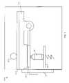
- FIG. 5illustrates one exemplary embodiment of an enclosed PSS 500 .
- a vial 560 to be sanitizedcan be placed on a spring loaded platen 570 by either a robotic or manual method for the case of a stand alone system.
- a seal assembly 540is pushed up by the spring platen 570 through the vial 560 to form a seal with a pressure chamber 530 .
- the pressure chamber 530can substantially form a pressure seal between the vial port and the seal assembly by reducing the pressure of the chamber to provide a substantial vacuum.
- the pressure chamber 530is evacuated to promote a light tight seal.
- the pressure chambermay operate as an interlock that disables radiation output unless a measurement signals from a pressure sensor in the chamber confirms that pressure in the chamber meets predetermined criteria (e.g., maintains at least a minimum threshold vacuum or positive applied pressure level), thus confirming that the vial port is properly seated in the seal assembly 540 and that the seal assembly 540 is properly seated against the pressure chamber 530 .
- predetermined criteriae.g., maintains at least a minimum threshold vacuum or positive applied pressure level
- the depicted exampleshows a hinged seal assembly. Other variations may include a rotating carousel of seal assemblies or simply a single fixed seal assembly.
- the pressure chamber 530may be at least partially enclosed on the top by UV transparent glass 520 or equivalent. The pressure/vacuum may be monitored in the chamber 530 to determine when to enable the UV source 510 . Other criteria may be used to enable the UV source such as a signal indicating a door 550 is closed to substantially contain radiation within the PSS 500 .
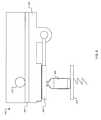
- FIG. 6illustrates an exemplary PSS 600 without walls surrounding the item to be sanitized 660 .
- the seal assembly 640is shown as a hinged seal assembly; other embodiments may include a rotating carousel of different seal assemblies or a single fixed seal assembly.
- Spring loaded platen 670can be used to push the vial 660 and seal assembly 640 upward to seat with the pressure chamber 630 .
- spring loaded platen 670can be omitted and the manipulator or operator can hold the vial 660 in the position to seat the seal assembly 640 .
- At least one seal assemblyis operable to provide an adjustable aperture (e.g., iris) or masking profile for controlling the size, shape, and/or location of the predetermined region to be exposed to the dose of radiation.
- an adjustable aperturee.g., iris
- the manipulator or operatormay release its grip of the vial 660 and rely on the vacuum to hold the vial 660 in place while sanitization process takes place.
- vacuumis generated indicating a proper seal, the UV source 610 is enabled and the dose is delivered though the UV transparent glass 620 to the port of the vial 660 .
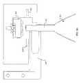
- FIG. 7shows an exemplary PSS 700 that includes a gripper and an axis of motion.
- the operatorin the manual case or robot places the vial 760 onto the platen 770 .
- the gripper 790is lowered by the motorized slide 780 and the vial 760 is picked up by the grip fingers 795 .
- the vial 760is then elevated to the seal assembly 740 which is seated against the pressure chamber 730 .
- a secondary light barriersuch as a baffle 750 may be used.
- pressure/vacuumis generated indicating a proper seal, the UV source 710 is enabled and the dose is delivered though the UV transparent glass 720 to the port of the vial 760 .
- UV energymay not be needed.
- some productse.g., sterile water bags
- UV light exposuremay not be affected by UV light exposure.
- personnel safety in terms of sufficient UV containmentis provided by, for example, the cell walls and doors
- sanitization in an enclosed settingmay not be required.
- processing and/or transport timesmay be reduced by simplified motion trajectories, thereby enhancing throughput for manual or automated sanitization processes.
- one or more optical sensorsmay be located in and around the PSS to detect the presence and/or intensity of “leaked” radiation that may escape from around the light seal, through the medical container, or otherwise, from the primary optical path between the radiation source and the predetermined target region.
- a controllermay monitor such sensors, and take some corrective action should the detected leakage exceed a predetermined level.
- corrective actionsmay include, but are not limited to, generating a notification signal (e.g., electronic message to an operator, warning light, or the like), disabling the radiation source, or attempting to reconfigure the light seal assembly by, for example, selecting a different light seal that may provide improved sealable engagement with the current medical container.
- a notification signale.g., electronic message to an operator, warning light, or the like
- the optimal available light seal for any (perhaps unrecognized) medical containermay be determined and recorded in a data store for use in future operations based on leakage sensor feedback.
- FIGS. 8A and 8Billustrates an exemplary IV bag and drug vial sanitization, respectively.
- a robot(not shown) grabs an IV bag 810 from a prior station (e.g., an IV bag scale or rack) using robot fingers 805 and transports the bag 810 to a PSS. The robot then places the bag port 815 into close proximity with a UV source 820 .
- a light or laser emitter 830 and detector 832are used to detect the presence or absence of a bag port.
- the emitter 830emits a light or laser beam that can be detected by the detector 832 .
- the beamis broken which then sends a signal to the controller (not shown) to enable the UV source 820 .
- the controllernot shown
- the port 815breaks the emitted beam, thereby enabling the UV source 820 to illuminate the portion of the port to be sanitized.
- the robotmoves the bag 810 to the next station, which could be any a scale, a temporary holding station, or a syringe manipulator.
- a shield/maskmay be used to prevent UV from hitting the bag contents or escaping into the cell.
- UV exposuremay not be an issue unless there are drugs in the bags.
- the escape of UV into the surrounding chamber or environmentmay be controlled by small clearances and/or the shape of the robot fingers 805 that can cover most of the opening. Surfaces of the robot or actuator that may be exposed to UV radiation may be treated to promote controlled reflection, absorption, diffusion, or a combination of these or other
- a flexible mask with a slitis used.
- the robotpushes the bag port through the slit so that the mask sits between the upper and lower protrusions of the robot fingers 805 . This effectively seals the entire lower portion of the light path, while leaving open the path between the robot fingers and the assembly surface just above it (where the emitter 830 sits).
- an appropriate movable aperture seal assembly 840is moved into alignment, based on the identifying information about the drug vial to be sanitized 812 .
- the movable seal assembly 840has some vertical compliance and rests just below two mating surfaces 850 when aligned.
- the two mating surfaces 850may be two machined surfaces.
- a robot(not shown) grabs the vial 812 from a prior station (e.g., vial weighing station or rack, container cover/seal removal station, or the like) using robot fingers 805 and takes the vial 812 directly underneath the seal assembly 840 .
- the robotthen moves the vial 812 upward, deforming a flexible mask 860 and bringing the movable seal assembly 840 into contact with the mating surfaces 850 .
- a vacuum port(not shown) is used to draw air from the chamber created as a result of the seal assembly 840 contacting the mating surfaces 850 .
- a pressure sensor(not shown) is used to measure the pressure inside the chamber. If the pressure decreases to a defined level, the vial 812 is in the correct position and a substantial light seal has been created. An o-ring or other gasket type material may be used with the mating surfaces to improve light seal.
- a UV source 820is then enabled, thereby illuminating the portion of the vial port 817 to be sanitized.
- the robotmoves the vial 812 to the next station, which could be a scale, a temporary holding station, or a syringe manipulator.
- light sealmay be provided by placing a cover over the drug vial to be sanitized.
- Some embodiments of the PSS chambermay be customized for the specific range of objects to be sanitized, taking into consideration requirements such as: object access requirements to the light source, object size, light containment, and distance of the object from the light source.
- the sealing systems or methodsmay be designed not to touch the areas of the stopper or fluid transfer port to be sanitized. This may help to protect the areas to be sanitized from both microbial and drug cross-contamination.
- aperture seal assemblies 910 a - fare designed to incorporate chamfered guides 920 a - f to aid engagement.
- an item to be sanitizede.g., a vial
- the operatorin the manual case
- robotcenters the item in the aperture 930 . If the item position on insertion is too far out, it will not engage.
- the size of the aperture 930is configured to be larger than the size of the areas to be sanitized, so if engaged the areas to be sanitized will not be touched and full exposure of the areas to be sanitized will be assured. Proper engagement provides sealing between the pressure chamber (not shown) and the seal assembly 910 .
- the seal assemblies 910 a - fcan be removed and/or interchanged from the rotating or fixed carousel 900 .
- a rigid, semi-rigid, or flexible gasket 940may be formed around an aperture 930 .
- an operator in a pharmacy or a robot arm in an APAS cellmay place the fluid port to be sanitized in proximity to the aperture 930 such that the gasket 940 forms a substantial light seal interface with a body of the vial or IV bag.
- the aperture 930may provide a substantially UV-transparent window through which one or more surfaces on the fluid port may be exposed to ultraviolet radiation through the window.
- the aperture gaskets 940 a - fmay generally include, but are not limited to, materials that are compliant to form a seal (e.g., silicone rubbers). Such materials may also be selected and screened to provide suitable resistance to heat and UV exposure for the applicable embodiments of the PSS.
- One embodimentcomprises several gasket apertures 930 a - f (see FIGS. 9A and 9B ) that combine to cover a wide range of vial seal/stopper diameters. Each aperture 930 may handle a sub range of vial top sizes. Sealing is achieved on the outer edge of the metal part of the vial top, removed from the stopper or port puncture area in the center.
- apertures 930 a - fmay be in fixed locations, or indexed via a variety of means to a fixed interface location. Guiding features may also be incorporated to guide the travel of the item to be sanitized into the exposure aperture. The quality of the seal is verified prior to and during exposure by monitoring the pressure/vacuum in the pressure chamber (not shown).
- some embodimentsmay provide a receptacle 910 f to receive a fluid port in proximity of the UV exposure port.
- the receptacle 910 fmay be sized to receive one or more sizes and styles of fluid ports for IV bags, and one or more sizes and styles of fluid ports for vials.
- a concave opening receptacle 910 fmay be adapted to receive a range of sizes.
- One or more differently sized and/or shaped receptaclesmay be provided.
- receptaclesmay be interchanged to accommodate a wide range of items to be sanitized.
- Different receptaclesmay have locating pins, rotating and/or sliding features to retain a receptacle being used.
- Interlock featuresmay be integrated into each receptacle. For example, proximity or pressure sensors may be used to determine when a receptacle is properly installed and a properly sized vial or IV bag fluid port is being inserted or pressed into the receptacle to be exposed to the ultraviolet radiation.
- the automated transfer mechanismmay provide at least a partial light seal around at least a portion of the opening on the PSS chamber wall.
- a manipulatormay be adapted to provide a thin (e.g., pencil-like) extension apparatus to extend the reach of the manipulator through a reduced width (e.g., narrower) slot in the narrow portion of the opening in the PSS chamber housing.
- Such extension apparatus, or the external portion of the manipulator itselfmay be provided with baffling to provide either an internal or an external light seal around some or all of the openings in the PSS chamber housing.
- a flexible rectangular bafflinge.g., plastic, rubber, or foam with reflective or absorptive coating
- a flexible rectangular bafflingmay be used to provide a substantial UV light seal over some or all of the narrow and/or wide openings in the PSS chamber housing when an object is positioned to receive UV radiation.
- the object to be sanitizedmay provide an effective light seal.
- the design of the baffles shown in FIGS. 3B-3Cmay be such that the object effectively seals the opening in the baffle when the object is brought into substantial contact with the baffle.
- the baffle designmay be compliant (e.g. flexible baffle material, spring mounted baffle assembly, or bellows) such that some tolerance in the positioning of the object against the baffle is afforded.
- the opening in the bafflemay be sized to maximize the amount of UV radiation on the targeted area to be sanitized.
- cooling and venting systemsmay be included to, for example, cool the UV source, cool the sealing materials and their mounting structures, cool the object(s) to be sanitized, and/or to remove ozone gas that may be generated by some UV sources.
- a typical implementation for cooling and ventingmay utilize the suction piped from the APAS exhaust fan plenum to draw cooling air through the PSS as required, and at the same time could be used to vent ozone if the applicable APAS cell has a vented exhaust.
- Another embodimentmay utilize local fans to provide cooling air, drawing air from the clean cell air to provide cooling. This air could flow back into the cell or be routed to the local exhaust air duct.
- both exhaust suction and local fansmay be combined to provide increased air flow, and/or to capture ozone.
- cooling aircan be obtained directly from HEPA filtered fan filter units.
- a combination of conductive and convective heat transfer mechanismsare used to manage the thermal load of the UV source.
- an ozone catalystmay be placed in the air flow to reduce the amount of ozone that is generated and re-circulated.
- the catalystin one example, may be local to the PSS housing to reduce its size and immediately reduce ozone levels.
- the catalystmay also be placed in line with the exhaust filter to scrub ozone repeatedly and/or when the cell operates in a recirculation mode.
- the input airmay be filtered to prevent particles from getting to the object(s) to be sanitized. The filtered air may also prevent particles from contacting the UV lamp, thereby increasing bulb life and efficiency.
- the PSSmay be designed for application within the APAS cell ISO class 5 clean air environment.
- FIG. 10is a block diagram of a control module 1000 for the illustrative PSS 300 of FIGS. 3A-3C .
- the PSS 300 discussed hereinmay include a PSS chamber, a UV lamp assembly, and the control module 1000 .
- the control module 1000may include a processing unit 1005 , a COM port 1010 , one or more sensors 1015 , an apparatus for operating an air handling system 1020 , an input/output (I/O) port 1025 , and a power supply 1030 .
- the processing unit 1005can be used to supervise, monitor, and control operations according to programmed instructions and/or hardware configurations (e.g., analog, digital, PAL, and/or ASIC circuits).
- the sensors 1015may include, but are not limited to, temperature, smoke, contaminant, vibration, position, and light intensity sensors.
- the I/O port 1025can be used to receive and send signals to the sensors 1015 and/or actuators (e.g., motors, UV lamp) in the PSS 300 .
- the control module 1000may send and/or receive status and control information to or from a host computer or controller via the COM port 1010 .
- the COM port 1010may be serial or parallel, and may use packet or non-packet based communication protocols (e.g., RS-232, USB, Firewire) to receive and/or send signals to a master controller.
- An example of the apparatus for operating an air handling system 1020was described with respect to FIG. 22 of U.S.
- control module 1000can combine to operate the PSS 300 to sanitize objects in pharmaceutical applications.
- a user interface 1035may be included.
- a stand alone devicewould be one example where a user interface 1035 would be included.
- a PSSmay use system information available to an APAS controller, for example, to optimize the UV sanitizing process.
- the APAS cell 100may contain the control module 1000 , as shown in reference to FIG. 10 , to control its operations that may transfer control information (e.g., indicative of the next object to be sanitized) to the PSS 300 via the COM port 1010 .
- control informationmay include optimal waveform, amplitude, pulse repetition number and rate, object size, type, and/or shape-related information.
- the controller in the PSS 300may respond by configuring the power supply 1030 and trigger controls to generate a sanitizing profile tailored to sanitize the next object.
- the robotic armmay be unable to perform other tasks during the UV sanitizing process.
- the robotic armmay release the object, perform one or more other actions, and return to grasp and convey the object after sanitization is complete.
- a dose of ultraviolet radiationmay be delivered.
- the dosemay be according to a pre-programmed set of instructions, at a specified intensity, duty cycle, repetition rate (e.g., fixed or variable), and number of pulses, or total energy.
- the start signalmay be generated by a switch that is pressed when the body of the object is pressed into the boot, or a proximity sensor (e.g., optical sensor, Hall effect sensor to detect robot arm, or the like) detects the fluid port in position or other relevant features, a signal generated by a controller or another switch (which may be manually pressed), or a combination of such these or other detection techniques.
- a UV light sensormay be provided to measure the UV light intensity to monitor the sufficiency of a light pulse. Sensors may be used to monitor the condition of the bulb(s) and the intensity of the emission and/or flash. This monitoring may take place during normal usage and/or as part of a regular maintenance schedule. The sensors may also be monitored to confirm that the appropriate light dose has been delivered. If, for example, the processing unit determines that a UV waveform fails to meet an average minimum threshold over multiple pulses, then the processing unit may generate a fault signal over the COM port 1010 .
- a sensormay measure the approximate total energy delivered, and send feedback information to a controller. The controller may enable UV output until a predetermined threshold of energy is delivered.
- the sensorscould be used as part of a regular (e.g., daily) self-diagnostic routine that would warn operators of diminished emission from the UV source, thus allowing for replacement of said source prior to failure.
- a fraction of the UV energyis tapped using mirrors or other reflective, or partly reflective, media. This allows the use of sensors having lower energy handling capacity to monitor the total output from a UV source.
- a sensore.g., light beam, proximity, contact, or vacuum/pressure
- the sensormay also be used to monitor the position or proximity of an item displaced by the presence of the object (e.g. switch) with respect to the bulb.
- the sensormay provide an interlock such that the bulb power cannot be enabled if the object is not in the correct position.
- Sensorsmay also be used to monitor airflow and shut down the system if inadequate airflow is detected.
- the bulb or array of bulbs/lamps/LEDsmay have temperature and air flow monitoring.
- interlocksmay advantageously provide enhanced operator safety in APAS cells and stand alone embodiments of the PSS, proper and reliable operation of the PSS, and/or protection of PSS equipment from damage or misuse.
- an interlockmay be provided to disable the light source until a portion of the object is in the PSS chamber such that a substantially complete light seal is formed to prevent substantial light from escaping.
- Suitable interlocksmay include, but are not limited to, temperature monitoring of light source(s), door(s) on the PSS or the APAS cell or both, light leakage sensing, vacuum seals, air flow, position sensors, ozone level monitoring, and laser.
- some embodimentsmay include a feedback signal to indicate to an operator that the UV profile has completed, or that the item to be sanitized has been exposed to the selected dose of UV.
- a displaymay indicate an exposure level, such as based on time, number of pulses delivered, or total energy delivered.
- the operatormay control the exposure level based on how long the item is pressed into the boot.
- the PSSoperates as follows.
- An automated transfer mechanismsuch as a robotic arm, retrieves a medical container (e.g., drug vial or IV bag) from an inventory.
- the controller of the PSS systemdetermines which radiation seal assembly corresponds to the medical container retrieved, based on the size and/or shape or the like of the medical container.
- the robot armcan then present the medical container to the ultraviolet light source of the PSS by engaging the medical container with the corresponding radiation seal assembly.
- the robot armcan place the medical container on a holding apparatus, which can then be actuated to couple the medical container with the corresponding radiation assembly proximate the UV source.
- the controllerthen instructs the UV light source to emit UV light at the correct intensity and for the needed duration to achieve the desired effect of sanitization of the exposed fluid transfer port (e.g., drug vial seal/stopper or port or IV bag injection port) either in a pulsed or continuous wave form.
- the exposed fluid transfer porte.g., drug vial seal/stopper or port or IV bag injection port
- the sealing/containment system or methodmay ensure that the drug or IV fluid container and/or contents is exposed to substantially reduced or no UV light as required.
- the sealing/containment system or methodmay be designed to only limit exposure to the operator, or not be included at all if the potential outcome of exposure is acceptable.
- the cooling, purging and or venting systemkeeps the PSS and item being sanitized cool and vents or otherwise controls the buildup of ozone gas if any.
- the control systemcontrols all aspects of the PSS operation. Monitoring on the system confirms that the correct UV exposure was produced, and that the target was in the correct location to receive the dose. Interlocks and safety mechanisms ensure that the UV source will not operate without appropriate safeguards or conditions in place.
- a fluid transfer operationmay be performed via the sanitized fluid transfer port.
- Some embodimentsmay provide one or more further features.
- the sanitization processmay be initiated by user input (e.g., by the touch of a button or other trigger device).
- user inpute.g., by the touch of a button or other trigger device.
- Theremay be audible and or visual indications to cue the operator or inform of progress.
- the operatormay have settings available for such things as exposure time, size of port, and height of vial for example.
- FIGS. 11A-11Fshow cross-sectional views of an illustrative PSS 1100 in the APAS cell 100 of FIG. 1 .
- the PS 1100can use a rotating platen 1105 with a perpendicular vertical wall 1110 to position an object 1115 to be sanitized. Except for differences as noted or where not applicable, the discussion above regarding embodiments of the PSS 300 are generally applicable to embodiments of the PSS 1100 .
- the PSS 300may operate using a control module, an example of which is described above with reference to FIG. 10 .
- the object 1115 to be sanitizedis loaded on the platen 1105 external to the PSS chamber.
- the platen 1105is rotated using an appropriate drive mechanism, (e.g., stepper motor, servo motor, mechanical linkage coupled to a solenoid) to position the object 1115 inside the PSS chamber where it can be exposed to the UV radiation 1120 .
- the vertical wall 1110serves as a baffle to substantially provide a light seal for the chamber that may keep most of the UV radiation 1120 from escaping.
- sensorse.g., encoder on platen shaft, index mark using Hall effect sensor, opto-interrupter, etc.
- sensorsmay be used to detect when the platen 1105 is in position for loading or pulsing, or when the walls 1110 are in a sealing position. While positioned in the chamber, the object 1115 may receive a dose of UV radiation, as has been described. The platen 1105 then rotates to position the object 1115 (portions of which may be substantially sanitized) outside of the PSS chamber, where it may be retrieved for further processing.
- the PSS 1100may be adapted for integration into an APAS cell 100 , or configured for stand-alone (e.g., table-top) operation for use in a hospital pharmacy or similar environment.
- pharmacy staffmay prepare prescriptions by loading one or more objects to be sanitized on the platen 1105 , perform the sanitizing, and retrieve the sanitized object for further processing after the platen 1105 rotates the object out of the chamber.
- Information indicating the form of medical containere.g., size, shape, type
- various data transfersmay involve packets of data, and/or error detection and correction to ensure data integrity.
- the wall 1110may further include multiple compartments (e.g., three, four, five, six, seven, eight or more) on the platen 1105 .
- the wallsmay be uniformly distributed such that when any of the compartments is exposed to the UV radiation 1120 , a portion of the wall 1110 is positioned to form a light seal.
- the platen 1105may be a circular or non-circular track. It may advance substantially continuously, or in segments according to chambers. In some embodiments, the platen 1105 may advance in response to a user command, such as from a keypad or “start” button. In other embodiments, the platen 1105 may advance upon detecting the weight of one or more objects to be processed.
- the PSS 1100may be configured to include other arrangements of a baffle 1125 , examples of which can be shown in FIGS. 11C , 11 D, 11 E, and 11 F.
- FIG. 12Fan illustrative embodiment of the PSS 1100 that includes a larger (or distributed) lamp system 1150 in combination with an illustrative embodiment of the baffle 1125 is shown in FIG. 12F .
- the UV radiation 1120can be distributed over a broader area.
- the baffling 1125 and reflective surface on the platen 1105can provide a broadly distributed UV radiation pattern over top and side surfaces of an object 1115 b .
- the platen 1105is carrying two objects 1115 a and 1115 b .
- the object 1115 bcan be in the PSS chamber, and the object 1115 a can be external to the PSS chamber.
- This multi-object carrying capability of the PSS system 1100can promote efficient handling, for example, in a hospital pharmacy environment in which UV sanitizing processing time may affect productivity and throughput.
- the platen 1105may be adapted to receive a tray of objects that are to be sanitized.
- a tray of two or more vials to be sanitizedmay be placed on portion of the platen 1105 that is external to the PSS chamber.
- the traysmay include carrying handles for convenient placement and/or stacking of vials. Such trays may be prepared in advance, and can later be efficiently batch processed, thereby saving time and labor for processing pharmaceutical admixtures.
- the entire PSS 1100may be designed for use within an ISO class 5 clean air environment.
- Such an environmentmay be present, for example, within a containment cabinet in an APAS cell, or present in a hospital pharmacy laminar airflow hood.
- An air cooling systemmay be used, if needed, to dissipate the heat in the lamp housing 1170 or chamber 1175 .
- UV sanitizing systemsmay be implemented using systems, methods, or computer program products other than the examples described above.
- a PSS systemmay communicate using suitable communication methods, equipment, and techniques.
- the PSS control modulemay communicate with the APAS control unit and/or a hospital pharmacy network using point-to-point communication in which a message is transported directly from the source to the receiver over a dedicated physical link (e.g., fiber optic link, point-to-point wiring, daisy-chain).
- a dedicated physical linke.g., fiber optic link, point-to-point wiring, daisy-chain
- Other embodimentsmay transport messages by broadcasting to all or substantially all devices that are coupled together by a communication network, for example.
- each PSS systemmay be programmed with the same information and be initialized with substantially identical information stored in non-volatile memory.
- one or more PSS systemsmay be custom configured to perform specific functions.
- one PSS systemmay be configured to perform both custom and batch processing functions by responding to information about the objects to be sanitized.
- an automated sanitizing system for a pharmacy environment for killing or incapacitating biocontaminantsmay present one or more objects to be sanitized.
- the systemcan include a chamber with a pulsed or constant wave form ultraviolet source.
- the systemfurther can include an automated transport mechanism to place an object to be sanitized into the chamber for exposure to ultraviolet radiation from the ultraviolet source.
- the automated transport mechanismmay further be to remove the object from the chamber after exposure to the ultraviolet radiation.
- the automated transport mechanismmay include a robotic manipulator and/or a rotating platen.
- the automated transport mechanismmay manipulate or move the object in response to a sequence of commands automatically generated by a processor executing a program of instructions.
- Wallsmay substantially enclose the chamber, at least one wall having an opening for receiving the object and a portion of the transport mechanism.
- the automated transport mechanismmay provide at least a partial light seal around at least a portion of the opening.
- the ultraviolet sourcemay provide ultraviolet radiation in response to a trigger signal.
- the controllermay generate one or more pulses or timed constant wave of a controlled waveform.
- the waveformmay be controlled to provide a desired amplitude, shape, and/or intensity.
- the controllermay generate a plurality of controlled pulses or constant wave according to a selected sanitizing routine.
- the selected sanitizing routinemay correspond to characteristics, such as type, size, or manufacturer, of the object to be sanitized.
- the controllermay receive messages over a communication link, and the messages may contain information about the characteristics of the object to be sanitized.
- the object to be sanitizedmay include a portion of a vial, an IV bag, or a syringe.
- the biocontaminants to be killed or incapacitatedmay include one or more viruses, bacteria, and/or fungi.
- the ultraviolet radiationmay include UV-A, UV-B, and/or UV-C wavelengths. Some embodiments may expose a fluid transfer port to be sanitized to a combined dose of both continuous and pulsed radiation over a predetermined period of time.
- Some systemsmay be stand-alone or table top systems; other systems may be adapted for integration into an APAS.
- a method of sanitizing at least one object surfacemay include generating a motion trajectory command to cause a transport mechanism to place an object within a chamber. The method may also include exposing at least a portion of the object to a dose of ultraviolet radiation.
- the dose of ultraviolet radiationmay include one or more pulses or timed constant wave.
- the methodmay further include identifying a number of pulses or constant wave of ultraviolet radiation that is sufficient to kill or incapacitate one or more types of biocontaminants to a selected degree.
- the selected degreemay be substantially all biocontaminants, such as at least 99.9999%, 99.99%, 99%, 95%, 90%, 80%, 75%, 70%, 60%, or at least about 50%. In some embodiments, between 1 and 100% of a particular biocontaminant may be killed or substantially incapacitated by the dose of ultraviolet radiation.
- FIG. 12shows an example of an apparatus 1200 for performing a fluid transfer operation. Exemplary aspects of a similar syringe manipulator apparatus are described, for example, with reference to FIG. 7 in U.S. patent application Ser. No. 11/937,846, entitled “Control of Fluid Transfer Operations,” and filed by Doherty, et al. on Nov. 9, 2007, the entire contents of which are herein incorporated by reference.
- the protective cover 1202covers a first fluid transfer port 1206 of a container 1208 .
- the container 1208also includes a second fluid transfer port 1210 . In one example, the fluid transfer operation is performed using the second fluid transfer port 1210 of the container 1208 .
- the container 1208is held by a container manipulator 1212 .
- the container manipulator 1212can move in a horizontal and vertical direction to align a particular container and fluid transfer port with the needle 1204 .
- a draw from a vialmay be performed as follows. First, the syringe plunger may be positioned to draw in a predetermined amount of air into the syringe barrel. This amount may be determined based on the required fluid volume of the prescription (first pull). The predetermined amount of air can replace the volume of fluid that is drawn with an approximately equal volume of air. So if 10 ml of fluid is being drawn, 10 ml of air can be pushed in to replace it. During this process, the system may estimate or monitor the ‘headspace’ in the vial. In a preferred embodiment, the method may maintain a slight negative pressure in the vial.
- the syringe plungercan be actuated to draw a predetermined amount of fluid from the vial. In this case it can generate a negative pressure. This can be limited so that pull does not exceed a force limit (e.g., by limiting motor current to a threshold level.)
- the syringe plungercan be actuated to push a volume of air into the vial to replace the volume of fluid removed.
- the syringe plungercan be retracted again to an amount approximately equal to the amount of air pumped into the vial.
- the cyclecan continue until the required amount of fluid is drawn into the syringe from the vial. Sixth, at the end of the cycling, the volume in the syringe can substantially match the required draw amount, and there can be a slight negative pressure in the vial.
- a draw from an IV bagmay be performed as follows.
- the IV bagmay hang by its fill port on the indexer of a needle down syringe manipulator station.
- the indexerthen moves the IV bag to a position under a syringe needle.
- the IV bag portthen engages the syringe needle.
- a syringe plungermay be withdrawn so that air is drawn out of the IV bag and into the syringe.
- the syringe plungermay be withdrawn until the change in torque, for example, is detected and, in some embodiments, for some additional time to give margin on the draw resulting in a small amount of fluid draw and/or an IV bag that is negatively pressurized relative to ambient pressure.
- the indexerthen lowers the IV bag.
Landscapes
- Health & Medical Sciences (AREA)
- General Physics & Mathematics (AREA)
- Physics & Mathematics (AREA)
- General Health & Medical Sciences (AREA)
- Public Health (AREA)
- Veterinary Medicine (AREA)
- Life Sciences & Earth Sciences (AREA)
- Animal Behavior & Ethology (AREA)
- Mechanical Engineering (AREA)
- Chemical & Material Sciences (AREA)
- Pharmacology & Pharmacy (AREA)
- Engineering & Computer Science (AREA)
- Toxicology (AREA)
- Nutrition Science (AREA)
- Epidemiology (AREA)
- Medicinal Chemistry (AREA)
- Chemical Kinetics & Catalysis (AREA)
- Apparatus For Disinfection Or Sterilisation (AREA)
- Medical Preparation Storing Or Oral Administration Devices (AREA)
Abstract
Description
Claims (56)
Priority Applications (2)
| Application Number | Priority Date | Filing Date | Title |
|---|---|---|---|
| US12/035,850US7931859B2 (en) | 2005-12-22 | 2008-02-22 | Ultraviolet sanitization in pharmacy environments |
| US13/073,613US8182744B2 (en) | 2005-12-22 | 2011-03-28 | Ultraviolet sanitization in pharmacy environments |
Applications Claiming Priority (7)
| Application Number | Priority Date | Filing Date | Title |
|---|---|---|---|
| US11/316,795US7610115B2 (en) | 2004-12-22 | 2005-12-22 | Automated pharmacy admixture system (APAS) |
| US11/389,995US7783383B2 (en) | 2004-12-22 | 2006-03-27 | Automated pharmacy admixture system (APAS) |
| US89143307P | 2007-02-23 | 2007-02-23 | |
| US97181507P | 2007-09-12 | 2007-09-12 | |
| US11/937,846US8267129B2 (en) | 2006-11-09 | 2007-11-09 | Control of fluid transfer operations |
| US98866007P | 2007-11-16 | 2007-11-16 | |
| US12/035,850US7931859B2 (en) | 2005-12-22 | 2008-02-22 | Ultraviolet sanitization in pharmacy environments |
Related Parent Applications (2)
| Application Number | Title | Priority Date | Filing Date |
|---|---|---|---|
| US11/316,795Continuation-In-PartUS7610115B2 (en) | 2004-12-22 | 2005-12-22 | Automated pharmacy admixture system (APAS) |
| US11/937,846Continuation-In-PartUS8267129B2 (en) | 2005-12-22 | 2007-11-09 | Control of fluid transfer operations |
Related Child Applications (1)
| Application Number | Title | Priority Date | Filing Date |
|---|---|---|---|
| US13/073,613ContinuationUS8182744B2 (en) | 2005-12-22 | 2011-03-28 | Ultraviolet sanitization in pharmacy environments |
Publications (2)
| Publication Number | Publication Date |
|---|---|
| US20080199353A1 US20080199353A1 (en) | 2008-08-21 |
| US7931859B2true US7931859B2 (en) | 2011-04-26 |
Family
ID=46330156
Family Applications (2)
| Application Number | Title | Priority Date | Filing Date |
|---|---|---|---|
| US12/035,850Active2027-04-01US7931859B2 (en) | 2005-12-22 | 2008-02-22 | Ultraviolet sanitization in pharmacy environments |
| US13/073,613ActiveUS8182744B2 (en) | 2005-12-22 | 2011-03-28 | Ultraviolet sanitization in pharmacy environments |
Family Applications After (1)
| Application Number | Title | Priority Date | Filing Date |
|---|---|---|---|
| US13/073,613ActiveUS8182744B2 (en) | 2005-12-22 | 2011-03-28 | Ultraviolet sanitization in pharmacy environments |
Country Status (1)
| Country | Link |
|---|---|
| US (2) | US7931859B2 (en) |
Cited By (45)
| Publication number | Priority date | Publication date | Assignee | Title |
|---|---|---|---|---|
| US20100012679A1 (en)* | 2008-07-15 | 2010-01-21 | Georgia-Pacific Consumer Products Lp | Dispensers For Dispensing a Flowable Product and Methods For Controlling the Dispensers |
| US20100012674A1 (en)* | 2008-07-15 | 2010-01-21 | Georgia-Pacific Consumer Products Lp | Sheet Product Dispensers and Methods For Controlling the Dispensers |
| US20100096042A1 (en)* | 2008-10-17 | 2010-04-22 | Co.Ri.M.A. S.R.L. | Machine For Filling Vials |
| US20100187443A1 (en)* | 2008-08-06 | 2010-07-29 | Sound Health Designs, LLC | System and method for germicidal sanitizing of an elevator or other enclosed structure |
| US20120261593A1 (en)* | 2011-04-18 | 2012-10-18 | Gilda Noori | Method and Device for Ultraviolet Light Sterilizing |
| US20120330152A1 (en)* | 2009-11-27 | 2012-12-27 | Claus-Peter Reisinger | Fluid management system |
| US8539989B2 (en)* | 2010-08-30 | 2013-09-24 | Health Robotics, S.r.l. | Method for the production of pharmaceutical products |
| US20140202588A1 (en)* | 2011-06-17 | 2014-07-24 | Kiro Robotics, S.L. | Machine and Method For The Automatic Preparation Of Intravenous Medication |
| US20140246603A1 (en)* | 2013-03-01 | 2014-09-04 | John Wilson | Mobile uva curing system and method for collision and cosmetic repair of vehicles |
| US20140261880A1 (en)* | 2011-10-28 | 2014-09-18 | Takazono Technology Incorporated | Liquid medication dispensing machine |
| US20150001192A1 (en)* | 2013-06-26 | 2015-01-01 | Apple Inc. | Electron beam conditioning |
| US20150251778A1 (en)* | 2014-03-05 | 2015-09-10 | Kabushiki Kaisha Yaskawa Denki | Robot system, liquid transfer controller, liquid transfer control method, and medicine manufacturing method |
| US20150251779A1 (en)* | 2014-03-05 | 2015-09-10 | Kabushiki Kaisha Yaskawa Denki | Robot system, liquid transfer controller, liquid transfer control method, and medicine manufacturing method |
| US20150251781A1 (en)* | 2014-03-05 | 2015-09-10 | Kabushiki Kaisha Yaskawa Denki | Liquid transfer system, liquid transfer control method, liquid transfer controller, and medicine manufacturing method |
| US20150251780A1 (en)* | 2014-03-05 | 2015-09-10 | Kabushiki Kaisha Yaskawa Denki | Fluid transfer apparatus, fluid transfer control method, fluid transfer controller, fluid transfer system, and medicine manufacturing method |
| US9173816B2 (en) | 2012-07-24 | 2015-11-03 | Intelligent Hospital Systems, Inc. | Closed system transfer device and automation system |
| US9474693B2 (en) | 2012-10-26 | 2016-10-25 | Baxter Corporation Englewood | Work station for medical dose preparation system |
| US9682345B2 (en) | 2014-07-08 | 2017-06-20 | Particle Measuring Systems, Inc. | Method of treating a cleanroom enclosure |
| USD790727S1 (en) | 2015-04-24 | 2017-06-27 | Baxter Corporation Englewood | Platform for medical dose preparation |
| US9919939B2 (en) | 2011-12-06 | 2018-03-20 | Delta Faucet Company | Ozone distribution in a faucet |
| US10089444B2 (en) | 2012-10-26 | 2018-10-02 | Baxter Corporation Englewood | Image acquisition for medical dose preparation system |
| US10347374B2 (en) | 2008-10-13 | 2019-07-09 | Baxter Corporation Englewood | Medication preparation system |
| US10793454B1 (en) | 2018-02-22 | 2020-10-06 | United States Of America As Represented By The Secretary Of The Air Force | Water treatment system with ultraviolet LEDs and photo-catalysts |
| USRE48245E1 (en)* | 2013-03-01 | 2020-10-06 | Spdi, Inc. | Mobile UVA curing system and method for collision and cosmetic repair of vehicles |
| US10818387B2 (en) | 2014-12-05 | 2020-10-27 | Baxter Corporation Englewood | Dose preparation data analytics |
| US10869961B2 (en) | 2017-11-06 | 2020-12-22 | Sorrel Medical Ltd. | Local disinfection for drug delivery system |
| US10869960B2 (en) | 2017-11-06 | 2020-12-22 | Sorrel Medical Ltd | Local disinfection for prefilled drug delivery system |
| US11013857B2 (en) | 2016-07-06 | 2021-05-25 | Bayer Healthcare Llc | Contrast heating system with in-line contrast warmer |
| US11027108B2 (en) | 2017-11-14 | 2021-06-08 | Sartorius Stedim North America Inc. | Fluid transfer assembly with a junction having multiple fluid pathways |
| US11107574B2 (en) | 2014-09-30 | 2021-08-31 | Baxter Corporation Englewood | Management of medication preparation with formulary management |
| IT202000010429A1 (en)* | 2020-05-08 | 2021-11-08 | Formenti & Giovenzana | Cabinet for sterilizing sources and corresponding procedure |
| US11319201B2 (en) | 2019-07-23 | 2022-05-03 | Sartorius Stedim North America Inc. | System for simultaneous filling of multiple containers |
| US11367533B2 (en) | 2014-06-30 | 2022-06-21 | Baxter Corporation Englewood | Managed medical information exchange |
| US11458214B2 (en) | 2015-12-21 | 2022-10-04 | Delta Faucet Company | Fluid delivery system including a disinfectant device |
| US11575673B2 (en) | 2014-09-30 | 2023-02-07 | Baxter Corporation Englewood | Central user management in a distributed healthcare information management system |
| US11577953B2 (en) | 2017-11-14 | 2023-02-14 | Sartorius Stedim North America, Inc. | System for simultaneous distribution of fluid to multiple vessels and method of using the same |
| US11584571B2 (en) | 2011-06-22 | 2023-02-21 | Sartorius Stedim North America Inc. | Vessel closures and methods for using and manufacturing same |
| US11691866B2 (en) | 2017-11-14 | 2023-07-04 | Sartorius Stedim North America Inc. | System for simultaneous distribution of fluid to multiple vessels and method of using the same |
| US11752502B2 (en)* | 2016-06-14 | 2023-09-12 | Diatron Mi Zrt. | Reagent pack with integrated waste reservoir |
| US20230285237A1 (en)* | 2022-03-08 | 2023-09-14 | Equashield Medical Ltd | Fluid transfer station in a robotic pharmaceutical preparation system |
| US11948112B2 (en) | 2015-03-03 | 2024-04-02 | Baxter Corporation Engelwood | Pharmacy workflow management with integrated alerts |
| US11957378B1 (en) | 2020-12-18 | 2024-04-16 | Northgate Technologies, Inc. | Anti-microbial surgical access device |
| US12239127B2 (en) | 2021-07-28 | 2025-03-04 | Sartorius Stedim North America Inc. | Thermal capacitors, systems, and methods for rapid freezing or heating of biological materials |
| US12252391B2 (en) | 2017-11-14 | 2025-03-18 | Sartorius Stedim North America Inc. | System for simultaneous distribution of fluid to multiple vessels and method of using the same |
| US12412644B2 (en) | 2014-10-24 | 2025-09-09 | Baxter Corporation Englewood | Automated exchange of healthcare information for fulfillment of medication doses |
Families Citing this family (74)
| Publication number | Priority date | Publication date | Assignee | Title |
|---|---|---|---|---|
| WO2006069361A2 (en)* | 2004-12-22 | 2006-06-29 | Intelligent Hospital Systems Ltd. | Automated pharmacy admixture system (apas) |
| US8271138B2 (en) | 2007-09-12 | 2012-09-18 | Intelligent Hospital Systems Ltd. | Gripper device |
| US8225824B2 (en)* | 2007-11-16 | 2012-07-24 | Intelligent Hospital Systems, Ltd. | Method and apparatus for automated fluid transfer operations |
| US8337770B2 (en)* | 2007-12-11 | 2012-12-25 | Wind Brian E | UV light writing instrument sterilizer |
| US20090250626A1 (en)* | 2008-04-04 | 2009-10-08 | Hexatech, Inc. | Liquid sanitization device |
| ES2321154B1 (en)* | 2009-01-19 | 2010-01-25 | Grifols, S.A. | DEVICE FOR AUTOMATIC EXTRACTION OF SAMPLES OF LIQUID FROM COLLECTING CONTAINERS AND PROCEDURE TO PERFORM SUCH EXTRACTION. |
| US8386070B2 (en) | 2009-03-18 | 2013-02-26 | Intelligent Hospital Systems, Ltd | Automated pharmacy admixture system |
| WO2010127296A2 (en)* | 2009-04-30 | 2010-11-04 | The Johns Hopkins University | Decontamination apparatus |
| ES3004613T3 (en) | 2009-07-29 | 2025-03-12 | Icu Medical Inc | Fluid transfer devices |
| NL1037222C2 (en)* | 2009-08-24 | 2011-02-28 | Easymeasure Developments B V | METHOD AND DEVICE FOR STERILIZING OR SCREENING OR PROCESSING A POPULATION OF ORGANISMS. |
| WO2011047293A1 (en)* | 2009-10-16 | 2011-04-21 | Hospira, Inc. | Ultraviolet sterilization system |
| US10046073B2 (en) | 2010-06-01 | 2018-08-14 | Bluemorph, Llc | Portable UV devices, systems and methods of use and manufacturing |
| WO2011153288A1 (en) | 2010-06-01 | 2011-12-08 | Alexander Farren | Uv sterilization of containers |
| US11260138B2 (en) | 2010-06-01 | 2022-03-01 | Bluemorph, Llc | UV sterilization of container, room, space or defined environment |
| US9687575B2 (en) | 2010-06-01 | 2017-06-27 | Bluemorph, Llc | UV devices, systems and methods for UV sterilization |
| WO2012166203A1 (en) | 2011-06-01 | 2012-12-06 | Alexander Farren | Uv sterilization of containers |
| US9387268B2 (en) | 2010-06-01 | 2016-07-12 | Alexander Farren | Compositions and methods for UV sterilization |
| US9024276B2 (en)* | 2010-06-23 | 2015-05-05 | Johnson & Johnson Vision Care, Inc. | Contact lens storage case surface disinfection |
| AU2012204462A1 (en) | 2011-01-05 | 2013-07-11 | Hospira, Inc. | Spray drying vancomycin |
| US8777054B2 (en)* | 2011-01-21 | 2014-07-15 | Parata Systems, Llc | Apparatus for dispensing solid articles and methods for using same |
| US8624203B2 (en)* | 2011-02-23 | 2014-01-07 | JLT & Associates, Inc. | Conveyor sterilization |
| US9093258B2 (en) | 2011-06-08 | 2015-07-28 | Xenex Disinfection Services, Llc | Ultraviolet discharge lamp apparatuses having optical filters which attenuate visible light |
| ES2606203T3 (en) | 2011-06-17 | 2017-03-23 | Kiro Robotics, S.L. | Machine and method for the automatic preparation of intravenous medication |
| JP5187469B1 (en)* | 2011-08-08 | 2013-04-24 | 株式会社湯山製作所 | Mixed injection device |
| US8399854B1 (en)* | 2011-08-24 | 2013-03-19 | Derek G. Crawford | Combination scale and germicidal sterilization apparatus |
| KR102145639B1 (en) | 2011-12-22 | 2020-08-19 | 아이씨유 메디칼 인코퍼레이티드 | Fluid transfer devices and methods of use |
| USD716966S1 (en) | 2012-07-31 | 2014-11-04 | Kiro Robotics, S.L. | Medical and laboratory equipment |
| JP6042545B2 (en) | 2012-08-23 | 2016-12-14 | 国立大学法人東京農工大学 | Highly transparent aluminum nitride single crystal layer and device comprising the same |
| US20140084179A1 (en)* | 2012-09-25 | 2014-03-27 | Hemalux Technologies LLC | Exposure chamber and a system for reduction of pathogens in a biological fluid using ultraviolet irradiation by light emitting diodes |
| EP2914303A1 (en)* | 2012-11-01 | 2015-09-09 | Covidien LP | System and method for treatment of a surface of an injection device |
| ES2397476B9 (en) | 2012-12-14 | 2014-06-05 | Kiro Robotics, S.L. | Handling tools for vials and system for the preparation of medicines comprising it |
| ES2826049T3 (en) | 2012-12-19 | 2021-05-17 | Purplesun Inc | Room divider with UV sterilization device |
| WO2014106196A1 (en)* | 2012-12-31 | 2014-07-03 | Sensor Electronic Technology, Inc. | Electronic gadget disinfection |
| US9974877B2 (en) | 2012-12-31 | 2018-05-22 | Sensor Electronic Technology, Inc. | Electronic gadget disinfection |
| WO2014120637A1 (en) | 2013-01-29 | 2014-08-07 | Hexatech, Inc. | Optoelectronic devices incorporating single crystalline aluminum nitride substrate |
| ITMI20130155A1 (en)* | 2013-02-05 | 2014-08-06 | Asr R Di Montagnani Valerio | DEVICE FOR HYGIENE OF MEDICAL INSTRUMENTS |
| JP2016520992A (en) | 2013-03-14 | 2016-07-14 | ヘクサテック,インコーポレイテッド | Power semiconductor device incorporating an aluminum nitride single crystal substrate |
| CN104043104B (en) | 2013-03-15 | 2018-07-10 | 浙江创新生物有限公司 | The spray dried powder and its industrialized process for preparing of hydrochloric vancomycin |
| WO2014149545A1 (en)* | 2013-03-15 | 2014-09-25 | Kap Medical | Method and apparatus for fluid sterilization for patient support surfaces |
| EP3043831A1 (en) | 2013-09-09 | 2016-07-20 | Covidien LP | Single-use device for injection of cartridge drugs |
| US10987684B2 (en) | 2013-10-11 | 2021-04-27 | 3M Innovative Properties Company | Nozzle assemblies, systems and related methods |
| US10035615B2 (en)* | 2013-10-11 | 2018-07-31 | Veltek Associates, Inc. | Method of packaging sterilized products |
| ES2805051T3 (en) | 2013-11-25 | 2021-02-10 | Icu Medical Inc | Procedures and system for filling I.V. bags with therapeutic liquid |
| US9931520B2 (en)* | 2013-12-19 | 2018-04-03 | Prs Medical Technologies, Inc. | Disinfection using light therapy |
| KR102268480B1 (en) | 2014-09-18 | 2021-06-23 | 제넥스 디스인펙션 서비시즈 인코퍼레이티드 | Room and area disinfection utilizing pulsed light with modulated power flux and light systems with visible light compensation between pulses |
| JP6577233B2 (en)* | 2015-05-11 | 2019-09-18 | 株式会社安川電機 | Automated working cell for biotechnology and medicinal chemistry, automated working method for biotechnology and medicinal chemistry, and automated working cell |
| ITUB20152979A1 (en)* | 2015-08-07 | 2017-02-07 | Saniplast S R L | AUTOMATIC STERILIZING DISTRIBUTOR OF DISPOSABLE DEVICES SUPPORTING THE FEMALE MINITION IN THE HEIGHT POSITION |
| EP4534065A3 (en) | 2015-12-04 | 2025-06-04 | ICU Medical, Inc. | Systems methods and components for transferring medical fluids |
| CN105616161B (en)* | 2016-03-01 | 2018-09-25 | 西安市第一医院 | A kind of quantitative negative pressure liquid dispensation apparatus |
| USD851745S1 (en) | 2016-07-19 | 2019-06-18 | Icu Medical, Inc. | Medical fluid transfer system |
| EP3487468B1 (en) | 2016-07-25 | 2025-10-01 | ICU Medical, Inc. | Systems and components for trapping air bubbles in medical fluid transfer modules and systems |
| US10850873B2 (en)* | 2016-08-04 | 2020-12-01 | Vanrx Pharmasystems Inc. | Apparatus and method for asepticaly filling pharmaceutical containers with a pharmaceutical fluid using rotary stage |
| DE102017004752A1 (en)* | 2017-05-18 | 2018-12-06 | Ebetech Gmbh | Method and device for sterilizing an object by means of a pulsed light source |
| WO2019143699A1 (en) | 2018-01-16 | 2019-07-25 | Purplesun Inc. | Adaptive multivector illumination delivery system |
| DE102018000575A1 (en) | 2018-01-24 | 2019-07-25 | Thermo Electron Led Gmbh | Laboratory device with UV irradiation device and disinfection method for a laboratory device |
| BR112021017269A2 (en) | 2019-03-15 | 2021-11-09 | Ecolab Usa Inc | System and method |
| CN114126670B (en) | 2019-07-03 | 2024-04-19 | 埃科莱布美国股份有限公司 | Touchscreen display surface disinfection using antimicrobial lights |
| WO2021108295A1 (en) | 2019-11-26 | 2021-06-03 | Ecolab Usa Inc. | Automated sanitization of robotic food equipment using antimicrobial light |
| WO2021113848A1 (en) | 2019-12-06 | 2021-06-10 | Purplesun Inc. | Proportionality of distributed illumination with adaptive multivector delivery system |
| US20210171231A1 (en)* | 2019-12-09 | 2021-06-10 | Revessel Inc | Robotic automated filling and capping system for vape oil cartridges |
| GB2608748B (en)* | 2020-03-06 | 2024-08-07 | Uv Partners Inc | UV disinfection platform |
| US11590057B2 (en) | 2020-04-03 | 2023-02-28 | Icu Medical, Inc. | Systems, methods, and components for transferring medical fluids |
| US11020502B1 (en) | 2020-05-01 | 2021-06-01 | Uv Innovators, Llc | Ultraviolet (UV) light emission device, and related methods of use, particularly suited for decontamination |
| US12156951B2 (en)* | 2020-05-20 | 2024-12-03 | The Boeing Company | System and method for disinfecting fuel tanks |
| CA3180011A1 (en) | 2020-05-29 | 2021-12-02 | Steven Randall HATCH | Microbial decontamination of common touch articles |
| WO2021242594A1 (en) | 2020-05-29 | 2021-12-02 | Ecolab Usa Inc. | Reducing microbial growth on packaged terminal air conditioners |
| WO2021247116A1 (en)* | 2020-06-05 | 2021-12-09 | Case Western Reserve University | Decontamination system |
| US11033645B1 (en)* | 2020-06-11 | 2021-06-15 | 1Lss, Inc | Apparatus for rapid disinfection of personal items |
| US11712488B2 (en) | 2020-06-11 | 2023-08-01 | 1Lss, Inc | Method and apparatus for rapid disinfection of personal items |
| EP3926034A1 (en)* | 2020-06-15 | 2021-12-22 | ESTR Biosystems GmbH | System for automatically operating a smart tank |
| CN112198163B (en)* | 2020-09-22 | 2023-11-21 | 无锡传奇科技有限公司 | Full-automatic syringe detection machine |
| WO2022250625A1 (en)* | 2021-05-24 | 2022-12-01 | Siskon Endustriyel Otomasyon Sistemleri Sanayi Ve Ticaret Anonim Sirketi | A drug preparation machine which can group drugs in a meal-based manner |
| WO2023204699A1 (en)* | 2022-04-17 | 2023-10-26 | The Compounding Company B.V. | Compounding system |
| WO2025181809A1 (en)* | 2024-02-29 | 2025-09-04 | Equashield Medical Ltd | An automated vial preparation module |
Citations (173)
| Publication number | Priority date | Publication date | Assignee | Title |
|---|---|---|---|---|
| US2275788A (en)* | 1939-02-01 | 1942-03-10 | Hobart Mfg Co | Sterilizer |
| US2988984A (en) | 1957-01-24 | 1961-06-20 | Pitney Bowes Inc | Article marking and orienting |
| US3002387A (en) | 1957-11-26 | 1961-10-03 | Standard Oil Co | Sealed sample injector for gas chromatography |
| US3556342A (en) | 1969-05-05 | 1971-01-19 | Joseph S Guarr | Medicine dispensing apparatus |
| US3878967A (en) | 1974-04-03 | 1975-04-22 | Sherwood Medical Ind Inc | Medicament dispenser |
| US3880211A (en) | 1971-10-18 | 1975-04-29 | Larry C Gess | Apparatus for filling containers |
| US3965945A (en) | 1974-09-09 | 1976-06-29 | Ross John D | Filling aid for medicant syringe |
| US4058121A (en) | 1976-06-29 | 1977-11-15 | American Hospital Supply Corporation | Vented needle for medical liquids |
| US4372464A (en) | 1980-06-16 | 1983-02-08 | Pepsico Inc. | Vending machine control circuit |
| US4464336A (en) | 1980-05-15 | 1984-08-07 | Ushio Denki Kabushikikaisha | Method of sterilization |
| US4634424A (en) | 1984-04-23 | 1987-01-06 | Windsor Medical, Inc. | Multiple re-entry implantable septum and method of using same |
| US4648430A (en) | 1984-06-22 | 1987-03-10 | Baxter Travenol Laboratories, Inc. | Device and method for collecting a desired weight amount of a material |
| US4669599A (en) | 1985-02-22 | 1987-06-02 | Advanced Semiconductor Materials Fico Tooling, B.V. | Apparatus and method for handling a workpiece |
| US4699186A (en) | 1986-02-26 | 1987-10-13 | Collagen Corporation | Laser fill-level indicator for blank syringes |
| US4706207A (en) | 1985-06-24 | 1987-11-10 | Nova Celltrak, Inc. | Count accuracy control means for a blood analyses system |
| US4730435A (en) | 1986-04-07 | 1988-03-15 | Aqua-Chem, Inc. | Sterile docking system for filling IV bags |
| US4811764A (en) | 1987-10-19 | 1989-03-14 | Mclaughlin John T | Medication dispenser station |
| US4829524A (en) | 1985-02-28 | 1989-05-09 | Canon Kabushiki Kaisha | Data communication apparatus |
| US4835372A (en) | 1985-07-19 | 1989-05-30 | Clincom Incorporated | Patient care system |
| US4835707A (en) | 1986-07-23 | 1989-05-30 | Takeda Chemical Industries, Ltd. | Automatic analysis method and apparatus for enzyme reaction |
| US4842028A (en)* | 1987-05-13 | 1989-06-27 | Baxter International Inc. | Fluid transfer apparatus |
| US4847764A (en) | 1987-05-21 | 1989-07-11 | Meditrol, Inc. | System for dispensing drugs in health care institutions |
| US4861335A (en) | 1985-07-26 | 1989-08-29 | Duoject Medical Systems Inc. | Syringe |
| US4871559A (en) | 1983-11-23 | 1989-10-03 | Maxwell Laboratories, Inc. | Methods for preservation of foodstuffs |
| US4878705A (en) | 1988-03-18 | 1989-11-07 | Texas Instruments Incorporated | Robot gripper passively locked |
| US4910942A (en) | 1983-11-23 | 1990-03-27 | Maxwell Laboratories, Inc. | Methods for aseptic packaging of medical devices |
| US4918604A (en) | 1988-10-03 | 1990-04-17 | Medco Containment Services, Inc. | Prescription drug depiction and labeling system |
| US4993598A (en) | 1988-05-18 | 1991-02-19 | Groninger & Co. Gmbh | Pump sterilization process and pumping system suitable for applying the process |
| US5004962A (en) | 1989-12-28 | 1991-04-02 | Arrow Marine, Inc. | Automatic motor synchronizer |
| US5020958A (en) | 1989-02-23 | 1991-06-04 | Philip Tuttobene | Article vending machine |
| US5034235A (en) | 1983-11-23 | 1991-07-23 | Maxwell Laboratories, Inc. | Methods for presevation of foodstuffs |
| US5122342A (en) | 1988-07-16 | 1992-06-16 | Quatro Biosystems Limited | Bio-fluid assay apparatus |
| US5129212A (en)* | 1990-11-08 | 1992-07-14 | Liqui-Box/B-Bar-B Corporation | Method and apparatus for automatically filling and sterilizing containers |
| US5144146A (en) | 1990-07-06 | 1992-09-01 | Ultraviolet Energy Generators, Inc. | Method for destruction of toxic substances with ultraviolet radiation |
| US5169642A (en) | 1988-06-24 | 1992-12-08 | Abbott Laboratories | Sustained-release drug dosage units |
| US5203385A (en) | 1992-03-31 | 1993-04-20 | Donald Waber | Apparatus and process for automatically reconstituting dry materials, especially pharmaceuticals |
| US5208762A (en) | 1990-12-06 | 1993-05-04 | Baxter International Inc. | Automated prescription vial filling system |
| CA1317262C (en) | 1989-02-28 | 1993-05-04 | Bohuslav J. Zezulka | Robotic drug dispensing system |
| US5229074A (en) | 1988-07-25 | 1993-07-20 | Precision Systems, Inc. | Automatic multiple-sample multiple-reagent chemical analyzer |
| US5260020A (en)* | 1992-09-17 | 1993-11-09 | Wilk Peter J | Method and apparatus for catheter sterilization |
| US5267174A (en) | 1989-09-29 | 1993-11-30 | Healthtech Services Corp. | Interactive medication delivery system |
| US5288285A (en) | 1993-02-16 | 1994-02-22 | Carter Wade P | Holder for filling syringe with radioactive liquid |
| US5309959A (en) | 1992-08-19 | 1994-05-10 | British Nuclear Fuels Plc | Dispensing apparatus |
| US5319543A (en) | 1992-06-19 | 1994-06-07 | First Data Health Services Corporation | Workflow server for medical records imaging and tracking system |
| US5324519A (en) | 1989-07-24 | 1994-06-28 | Atrix Laboratories, Inc. | Biodegradable polymer composition |
| US5339421A (en) | 1991-03-22 | 1994-08-16 | International Business Machines Corporation | General data stream parser for encoding and decoding data and program interface for same |
| US5337919A (en) | 1993-02-11 | 1994-08-16 | Dispensing Technologies, Inc. | Automatic dispensing system for prescriptions and the like |
| US5341854A (en) | 1989-09-28 | 1994-08-30 | Alberta Research Council | Robotic drug dispensing system |
| US5348585A (en) | 1993-01-07 | 1994-09-20 | Weston Colin K | Liquid dispensing apparatus |
| DE4314657A1 (en) | 1993-05-04 | 1994-11-10 | Friedhelm Sehrt | Safety device for the safe handling of liquid substances by means of a syringe, in particular for the metering and racking-off of liquids detrimental to health |
| US5363885A (en) | 1993-06-02 | 1994-11-15 | R. J. Reynolds Tobacco Company | Robotic sample preparation system and method |
| US5366896A (en) | 1991-07-30 | 1994-11-22 | University Of Virginia Alumni Patents Foundation | Robotically operated laboratory system |
| US5411489A (en) | 1994-05-06 | 1995-05-02 | Sterling Winthrop Inc. | Pre-filled syringe and pre-filled cartridge having actuating cylinder/plunger rod combination for reducing syringing force |
| US5431201A (en) | 1993-12-03 | 1995-07-11 | Technology 2000 Incororated | Robotic admixture system |
| US5451528A (en) | 1992-03-27 | 1995-09-19 | Abbott Laboratories | Methods for providing homogeneous reagents |
| US5479969A (en) | 1992-08-19 | 1996-01-02 | British Nuclear Fuels Plc | Apparatus for dispensing substances which are biologically hazardous |
| US5502944A (en) | 1993-12-03 | 1996-04-02 | Owen Healthcare, Inc. | Medication dispenser system |
| US5522804A (en) | 1994-02-15 | 1996-06-04 | Lynn; Lawrence A. | Aspiration, mixing, and injection syringe |
| US5522512A (en) | 1994-05-09 | 1996-06-04 | Merck & Co., Inc. | System and method for automatically feeding, inspecting and diverting tablets for continuous filling of tablet containers |
| US5533606A (en) | 1994-09-13 | 1996-07-09 | Yuyama; Shoji | Apparatus for storing and transporting drugs |
| US5534222A (en) | 1995-07-11 | 1996-07-09 | Purity Packaging A Division Of Great Pacific Enterprises | Method for sterilizing internal surfaces of an edible liquid packaging machine |
| US5573042A (en) | 1995-05-16 | 1996-11-12 | Dibra S.P.A. | Process for the preparation of prefilled syringes without residual gas bubbles |
| US5597995A (en) | 1995-11-08 | 1997-01-28 | Automated Prescription Systems, Inc. | Automated medical prescription fulfillment system having work stations for imaging, filling, and checking the dispensed drug product |
| US5611051A (en) | 1993-11-22 | 1997-03-11 | Enterprise Systems, Inc. | Point of supply use distribution process and apparatus |
| US5635394A (en) | 1995-03-31 | 1997-06-03 | Braun Intertec Corporation | Arrangement for air purification |
| US5660305A (en) | 1994-08-02 | 1997-08-26 | Medco Containment Services, Inc. | Automatic prescription dispensing system |
| US5666410A (en) | 1995-12-05 | 1997-09-09 | Mclane; Jerry | Automatic sterilizer for telephones and the method of use therefore |
| US5680858A (en) | 1992-12-10 | 1997-10-28 | Novo Nordisk A/S | Method and apparatus for in vivo determination of the concentration in a body fluid of metabolically significant substances |
| US5700998A (en) | 1995-10-31 | 1997-12-23 | Palti; Yoram | Drug coding and delivery system |
| US5713487A (en) | 1996-03-11 | 1998-02-03 | Scriptpro L.L.C. | Medicament verification in an automatic dispening system |
| US5713485A (en) | 1995-10-18 | 1998-02-03 | Adds, Inc. | Drug dispensing system |
| US5744094A (en) | 1991-04-12 | 1998-04-28 | Elopak Systems Ag | Treatment of material |
| US5768853A (en) | 1996-02-15 | 1998-06-23 | Purepulse Technologies, Inc. | Deactivation of microorganisms |
| US5769086A (en) | 1995-12-06 | 1998-06-23 | Biopsys Medical, Inc. | Control system and method for automated biopsy device |
| US5786598A (en) | 1996-05-22 | 1998-07-28 | Purepulse Technologies, Inc. | Sterilization of packages and their contents using high-intensity, short-duration pulses of incoherent, polychromatic light in a broad spectrum |
| US5797515A (en) | 1995-10-18 | 1998-08-25 | Adds, Inc. | Method for controlling a drug dispensing system |
| US5798020A (en) | 1997-06-23 | 1998-08-25 | Scriptpro, Llc | Medicine vial labeler |
| US5805454A (en) | 1995-08-10 | 1998-09-08 | Valerino, Sr.; Fred M. | Parenteral products automation system (PPAS) |
| US5812410A (en) | 1995-12-14 | 1998-09-22 | Rx Excel, Inc. | System for dispensing drugs |
| US5832447A (en) | 1994-05-24 | 1998-11-03 | Envoy Corporation | Automated system and method for providing real-time verification of health insurance eligibility |
| US5839836A (en) | 1995-10-19 | 1998-11-24 | Yuyama, Mfg. Co., Ltd. | Printing apparatus for medicine bag |
| US5848593A (en) | 1994-12-16 | 1998-12-15 | Diebold, Incorporated | System for dispensing a kit of associated medical items |
| US5884273A (en) | 1996-05-16 | 1999-03-16 | Carmen M Neal | Micro-computer and printer for printing a prescription slip |
| US5884457A (en) | 1997-02-05 | 1999-03-23 | Smithkline Beecham Corporation | Method and apparatus for automatically producing a plurality of sterile liquid filled delivery devices |
| US5895019A (en) | 1996-09-03 | 1999-04-20 | Micron Electronics, Inc. | Positioner for overhanging components |
| US5900211A (en) | 1995-10-26 | 1999-05-04 | Purepulse Technologies | Deactivation of organisms using high-intensity pulsed polychromatic light |
| US5907493A (en) | 1997-01-31 | 1999-05-25 | Innovation Associates, Inc. | Pharmaceutical dispensing system |
| US5911252A (en) | 1997-04-29 | 1999-06-15 | Cassel; Douglas | Automated syringe filling system for radiographic contrast agents and other injectable substances |
| US5912818A (en) | 1993-01-25 | 1999-06-15 | Diebold, Incorporated | System for tracking and dispensing medical items |
| US5948360A (en) | 1994-07-11 | 1999-09-07 | Tekmar Company | Autosampler with robot arm |
| US5963641A (en) | 1995-09-12 | 1999-10-05 | Markzware, Inc. | Device and method for examining, verifying, correcting and approving electronic documents prior to printing, transmission or recording |
| US5971593A (en) | 1994-12-16 | 1999-10-26 | Diebold, Incorporated | Dispensing system for medical items |
| US5993046A (en) | 1993-01-25 | 1999-11-30 | Diebold, Incorporated | System for dispensing medical items by brand or generic name |
| US6006946A (en) | 1997-12-05 | 1999-12-28 | Automated Prescriptions System, Inc. | Pill dispensing system |
| US6037598A (en) | 1998-01-28 | 2000-03-14 | Tetra Laval Holdings & Finance, Sa | Arrangement on an ultraviolet sterilization system |
| US6048086A (en) | 1995-08-10 | 2000-04-11 | Valerino, Sr.; Fred M. | Parenteral products automatic system (PPAS) with an oral/solid interface |
| US6060022A (en) | 1996-07-05 | 2000-05-09 | Beckman Coulter, Inc. | Automated sample processing system including automatic centrifuge device |
| US6082987A (en) | 1997-02-20 | 2000-07-04 | Technology Resources International Corporation | Apparatus for assembling a lens-forming device |
| US6096561A (en) | 1992-03-27 | 2000-08-01 | Abbott Laboratories | Scheduling operation of an automated analytical system |
| US6108588A (en) | 1993-01-25 | 2000-08-22 | Diebold, Incorporated | Restocking method for medical item dispensing system |
| US6141412A (en) | 1994-06-01 | 2000-10-31 | Davox Corporation | Unscheduled event task processing system |
| US6155485A (en) | 1998-11-09 | 2000-12-05 | Scriptpro Llc | Medicament dispensing station |
| US6161141A (en) | 1994-06-08 | 2000-12-12 | Hughes Electronics Corporation | Network system with TCP/IP protocol spoofing |
| US6181979B1 (en) | 1997-01-13 | 2001-01-30 | Kabushiki Kaisha Yuyama Seisakusho | Medication processing system |
| US6181982B1 (en) | 1997-02-26 | 2001-01-30 | Kabushiki Kaisha Yuyama Seisakusho | Drug dispenser and quantity input device |
| US6200289B1 (en) | 1998-04-10 | 2001-03-13 | Milestone Scientific, Inc. | Pressure/force computer controlled drug delivery system and the like |
| US6202004B1 (en) | 1995-08-10 | 2001-03-13 | Fred M. Valerino, Sr. | Autoacceptertube delivery system with a robotic interface |
| US6202923B1 (en) | 1999-08-23 | 2001-03-20 | Innovation Associates, Inc. | Automated pharmacy |
| US6203535B1 (en) | 1996-05-13 | 2001-03-20 | B. Braun Medical, Inc. | Method of making and using a flexible, multiple-compartment drug container |
| US6249717B1 (en) | 1996-11-08 | 2001-06-19 | Sangstat Medical Corporation | Liquid medication dispenser apparatus |
| US6249774B1 (en) | 1998-02-23 | 2001-06-19 | Bergen Brunswig Corporation | Method for owning, managing, automatically replenishing, and invoicing inventory items |
| US6279724B1 (en) | 1997-12-19 | 2001-08-28 | Semitoll Inc. | Automated semiconductor processing system |
| US20010018937A1 (en) | 1998-12-28 | 2001-09-06 | Shigeru Nemoto | Method and device for pre-filling a syringe with a contrast agent |
| US6343690B1 (en) | 1999-10-18 | 2002-02-05 | Coulter International Corp. | Specimen carrier for automated transport system and method and apparatus for identifying same |
| US20020020459A1 (en) | 2000-08-10 | 2002-02-21 | Baldwin Brian Eugene | Method, system, and apparatus for handling, labeling, filling and capping syringes |
| US6355024B1 (en) | 1999-07-14 | 2002-03-12 | Mallinckrodt Inc. | Medical fluid delivery system |
| US20020035412A1 (en) | 1999-12-03 | 2002-03-21 | Kircher Joseph J. | Method and apparatus for controlling the strategy of compounding pharmaceutical admixtures |
| US6360794B1 (en) | 2000-12-19 | 2002-03-26 | Bechtel Bwxt Idaho, Llc | Apparatus and method for delivering a fluid to a container |
| US6370841B1 (en) | 1999-12-03 | 2002-04-16 | Automed Technologies, Inc. | Automated method for dispensing bulk medications with a machine-readable code |
| USRE37829E1 (en) | 1990-12-06 | 2002-09-03 | Automed Technologies, Inc. | Automated prescription vial filling system |
| US6461568B1 (en) | 1998-12-23 | 2002-10-08 | Uv-Solutions, Llc | Method and apparatus for sterilizing small objects |
| US20020146343A1 (en) | 2000-12-14 | 2002-10-10 | Jenkins Geoffrey H. | Method and apparatus for rapidly sterilizing small objects |
| US6477442B1 (en) | 1995-08-10 | 2002-11-05 | Fred M. Valerino, Sr. | Autoacceptertube delivery system with a robotic interface |
| US20030046114A1 (en) | 2001-08-28 | 2003-03-06 | Davies Richard J. | System, method, and apparatus for storing, retrieving, and integrating clinical, diagnostic, genomic, and therapeutic data |
| IT1316152B1 (en) | 2000-12-15 | 2003-03-28 | Biomedical Technology Consulti | METHOD AND PLANT FOR THE PREPARATION AND DISTRIBUTION OF DRUGS. |
| US6564121B1 (en) | 1999-09-22 | 2003-05-13 | Telepharmacy Solutions, Inc. | Systems and methods for drug dispensing |
| US6566659B1 (en) | 1996-02-15 | 2003-05-20 | Purepulse Technologies, Inc. | Parametric control in pulsed light sterilization |
| US20030097368A1 (en) | 2001-11-21 | 2003-05-22 | Forhealth Technologies, Inc. | Serial data capture and processing |
| US6592816B1 (en) | 1999-03-01 | 2003-07-15 | Johnson & Johnson Vision Care, Inc. | Sterilization system |
| US6599476B1 (en) | 1997-11-27 | 2003-07-29 | A.I. Scientific Pty Ltd. | Sample distribution apparatus/system |
| US20030147770A1 (en)* | 2001-05-17 | 2003-08-07 | Purepulse Technologies, Inc. | Light treatment monitoring and data collection in a fluid treatment system using light for the treatment of fluid products |
| US6604903B2 (en) | 2001-11-30 | 2003-08-12 | Forhealth Technologies, Inc. | Automated drug vial safety cap removal |
| US6616771B2 (en) | 2001-11-30 | 2003-09-09 | Forhealth Technologies, Inc. | Method and system for cleaning and reusing a cannula |
| US20030216831A1 (en) | 1999-09-22 | 2003-11-20 | Telepharmacy Solutions, Inc. | Systems and methods for dispensing medical products |
| US6673048B1 (en) | 2000-05-24 | 2004-01-06 | Acist Medical Systems, Inc. | Pressure sleeve assembly |
| US20040028553A1 (en) | 2001-12-13 | 2004-02-12 | Xenon Corporation | Use of pulsed light to deactivate toxic and pathogenic bacteria |
| US20040034447A1 (en) | 2002-08-09 | 2004-02-19 | Mckesson Automation Sys Inc | Prescription filling apparatus implementing a pick and place method |
| US6722404B2 (en) | 2001-11-15 | 2004-04-20 | Forhealth Technologies, Inc. | Syringe bandolier with control feature |
| US20040099869A1 (en) | 2002-11-21 | 2004-05-27 | Remigijus Gaska | Light emitting heterostructure |
| US20040104243A1 (en) | 2002-12-03 | 2004-06-03 | Forhealth Technologies, Inc. | Automated means for removing, parking and replacing a syringe tip cap from a syringe |
| US20040123567A1 (en) | 2002-08-07 | 2004-07-01 | Medco Health Solutions, Inc. | Automated container bulking system and method optionally integrated with automated dispensing system and/or automated labeling and packaging system |
| US20040154690A1 (en) | 2002-12-03 | 2004-08-12 | Osborne Joel A. | Automated apparatus and process for reconstitution and delivery of medication to an automated syringe preparation apparatus |
| US20040193317A1 (en) | 2001-11-30 | 2004-09-30 | Richard Lunak | Filling a restocking package using a carousel |
| US20040241041A1 (en) | 1998-09-15 | 2004-12-02 | Archie Woodworth | Apparatus and method for fabricating a reconstitution assembly |
| US20040249498A1 (en) | 1997-12-05 | 2004-12-09 | William Jeffrey P. | Pill dispensing system |
| US20040250842A1 (en) | 2003-06-10 | 2004-12-16 | Adams John A. | Device and method for cleaning a tube |
| US6832844B2 (en) | 2002-12-03 | 2004-12-21 | Field Controls, L.L.C. | Ultraviolet lamp assembly |
| US20050045242A1 (en) | 2002-12-03 | 2005-03-03 | Osborne Joel A. | Automated means of storing, dispensing and orienting injectable drug vials for a robotic application |
| US6877530B2 (en) | 2002-12-03 | 2005-04-12 | Forhealth Technologies, Inc. | Automated means for withdrawing a syringe plunger |
| US6883681B1 (en)* | 1998-12-10 | 2005-04-26 | Scriptpro Llc | Automatic dispensing system for unit medicament packages |
| US20050133729A1 (en) | 2003-12-23 | 2005-06-23 | Archie Woodworth | Apparatus and method for fabricating a reconstitution assembly |
| US20050224137A1 (en) | 2004-04-07 | 2005-10-13 | Dennis Tribble | Device for reconstituting a drug vial and transferring the contents to a syringe in an automated matter |
| US20050252574A1 (en) | 2004-05-13 | 2005-11-17 | Khan Abdul W | Medication dose underfill detection system and application in an automated syringe preparing system |
| US20050252572A1 (en) | 2004-05-13 | 2005-11-17 | Wahid Khan | Automated use of a vision system to detect foreign matter in reconstituted drugs before transfer to a syringe |
| US20050279419A1 (en) | 2004-06-21 | 2005-12-22 | Dennis Tribble | Automated use of a vision system to unroll a label to capture and process drug identifying indicia present on the label |
| US6985870B2 (en) | 2002-01-11 | 2006-01-10 | Baxter International Inc. | Medication delivery system |
| US6986234B2 (en) | 2003-06-27 | 2006-01-17 | Forhealth Technologies, Inc. | System and method for bandoliering syringes |
| US6991002B2 (en) | 2002-12-03 | 2006-01-31 | Forhealth Technologies, Inc. | Tamper evident syringe tip cap and automated method for preparing tamper-evident syringes |
| US7007443B2 (en) | 2003-06-27 | 2006-03-07 | Forhealth Technologies, Inc. | System and method for bandoliering syringes |
| US20060136095A1 (en) | 2004-12-22 | 2006-06-22 | Rob Ronald H | Automated pharmacy admixture system (APAS) |
| US7100792B2 (en) | 2002-08-30 | 2006-09-05 | Omnicell, Inc. | Automatic apparatus for storing and dispensing packaged medication and other small elements |
| US7108679B2 (en) | 2004-03-11 | 2006-09-19 | Becton, Dickinson And Company | Intradermal syringe and needle assembly |
| US20060224414A1 (en) | 2005-03-31 | 2006-10-05 | Astrup Christopher B | System and method for providing prescription refills |
| US20060225383A1 (en) | 2005-04-08 | 2006-10-12 | Jm Smith Corporation | Pharmaceutical singulation counting and dispensing system |
| US20060259195A1 (en) | 2004-12-22 | 2006-11-16 | Eliuk Walter W | Automated pharmacy admixture system (APAS) |
| US7278813B2 (en) | 2000-07-07 | 2007-10-09 | Semitool, Inc. | Automated processing system |
| US20080114328A1 (en) | 2006-11-09 | 2008-05-15 | Intelligent Hospital Systems Ltd. | Control of Fluid Transfer Operations |
| US7403901B1 (en) | 2000-04-13 | 2008-07-22 | Accenture Llp | Error and load summary reporting in a health care solution environment |
| US20090067973A1 (en) | 2007-09-12 | 2009-03-12 | Intelligent Hospital Systems Ltd. | Gripper Device |
| WO2009033283A1 (en) | 2007-09-12 | 2009-03-19 | Intelligent Hospital Systems Ltd. | Gripper device |
| US20090126825A1 (en) | 2007-11-16 | 2009-05-21 | Intelligent Hospital Systems Ltd. | Method and Apparatus for Automated Fluid Transfer Operations |
| US20090138340A1 (en) | 2007-11-28 | 2009-05-28 | Borr Christopher A | Method, apparatus and computer program code for evaluating performance based on projected return and estimated cost |
| US7630788B1 (en) | 2001-06-18 | 2009-12-08 | Diebold, Incorporated | Pharmaceutical system in which pharmaceutical care is provided by a remote professional serving multiple pharmacies |
Family Cites Families (2)
| Publication number | Priority date | Publication date | Assignee | Title |
|---|---|---|---|---|
| US5009654A (en)* | 1989-03-10 | 1991-04-23 | Baxter International Inc. | Sterile product and method for sterilizing and assembling such product |
| FR2865135B1 (en)* | 2004-01-20 | 2007-10-05 | Serac Group | STERILIZATION INSTALLATION OF ARTICLES BY ELECTRONIC BOMBING |
- 2008
- 2008-02-22USUS12/035,850patent/US7931859B2/enactiveActive
- 2011
- 2011-03-28USUS13/073,613patent/US8182744B2/enactiveActive
Patent Citations (190)
| Publication number | Priority date | Publication date | Assignee | Title |
|---|---|---|---|---|
| US2275788A (en)* | 1939-02-01 | 1942-03-10 | Hobart Mfg Co | Sterilizer |
| US2988984A (en) | 1957-01-24 | 1961-06-20 | Pitney Bowes Inc | Article marking and orienting |
| US3002387A (en) | 1957-11-26 | 1961-10-03 | Standard Oil Co | Sealed sample injector for gas chromatography |
| US3556342A (en) | 1969-05-05 | 1971-01-19 | Joseph S Guarr | Medicine dispensing apparatus |
| US3880211A (en) | 1971-10-18 | 1975-04-29 | Larry C Gess | Apparatus for filling containers |
| US3878967A (en) | 1974-04-03 | 1975-04-22 | Sherwood Medical Ind Inc | Medicament dispenser |
| US3965945A (en) | 1974-09-09 | 1976-06-29 | Ross John D | Filling aid for medicant syringe |
| US4058121A (en) | 1976-06-29 | 1977-11-15 | American Hospital Supply Corporation | Vented needle for medical liquids |
| US4464336A (en) | 1980-05-15 | 1984-08-07 | Ushio Denki Kabushikikaisha | Method of sterilization |
| US4372464A (en) | 1980-06-16 | 1983-02-08 | Pepsico Inc. | Vending machine control circuit |
| US5034235A (en) | 1983-11-23 | 1991-07-23 | Maxwell Laboratories, Inc. | Methods for presevation of foodstuffs |
| US4910942A (en) | 1983-11-23 | 1990-03-27 | Maxwell Laboratories, Inc. | Methods for aseptic packaging of medical devices |
| US4871559A (en) | 1983-11-23 | 1989-10-03 | Maxwell Laboratories, Inc. | Methods for preservation of foodstuffs |
| US4634424A (en) | 1984-04-23 | 1987-01-06 | Windsor Medical, Inc. | Multiple re-entry implantable septum and method of using same |
| US4648430A (en) | 1984-06-22 | 1987-03-10 | Baxter Travenol Laboratories, Inc. | Device and method for collecting a desired weight amount of a material |
| US4669599A (en) | 1985-02-22 | 1987-06-02 | Advanced Semiconductor Materials Fico Tooling, B.V. | Apparatus and method for handling a workpiece |
| US4829524A (en) | 1985-02-28 | 1989-05-09 | Canon Kabushiki Kaisha | Data communication apparatus |
| US4706207A (en) | 1985-06-24 | 1987-11-10 | Nova Celltrak, Inc. | Count accuracy control means for a blood analyses system |
| US4835372A (en) | 1985-07-19 | 1989-05-30 | Clincom Incorporated | Patient care system |
| US4861335A (en) | 1985-07-26 | 1989-08-29 | Duoject Medical Systems Inc. | Syringe |
| US4699186A (en) | 1986-02-26 | 1987-10-13 | Collagen Corporation | Laser fill-level indicator for blank syringes |
| US4730435A (en) | 1986-04-07 | 1988-03-15 | Aqua-Chem, Inc. | Sterile docking system for filling IV bags |
| US4835707A (en) | 1986-07-23 | 1989-05-30 | Takeda Chemical Industries, Ltd. | Automatic analysis method and apparatus for enzyme reaction |
| US4842028A (en)* | 1987-05-13 | 1989-06-27 | Baxter International Inc. | Fluid transfer apparatus |
| US4847764A (en) | 1987-05-21 | 1989-07-11 | Meditrol, Inc. | System for dispensing drugs in health care institutions |
| US4847764C1 (en) | 1987-05-21 | 2001-09-11 | Meditrol Inc | System for dispensing drugs in health care instituions |
| US4811764A (en) | 1987-10-19 | 1989-03-14 | Mclaughlin John T | Medication dispenser station |
| US4878705A (en) | 1988-03-18 | 1989-11-07 | Texas Instruments Incorporated | Robot gripper passively locked |
| US4993598A (en) | 1988-05-18 | 1991-02-19 | Groninger & Co. Gmbh | Pump sterilization process and pumping system suitable for applying the process |
| US5169642A (en) | 1988-06-24 | 1992-12-08 | Abbott Laboratories | Sustained-release drug dosage units |
| US5122342A (en) | 1988-07-16 | 1992-06-16 | Quatro Biosystems Limited | Bio-fluid assay apparatus |
| US5229074A (en) | 1988-07-25 | 1993-07-20 | Precision Systems, Inc. | Automatic multiple-sample multiple-reagent chemical analyzer |
| US4918604A (en) | 1988-10-03 | 1990-04-17 | Medco Containment Services, Inc. | Prescription drug depiction and labeling system |
| US5020958A (en) | 1989-02-23 | 1991-06-04 | Philip Tuttobene | Article vending machine |
| CA1317262C (en) | 1989-02-28 | 1993-05-04 | Bohuslav J. Zezulka | Robotic drug dispensing system |
| US5324519A (en) | 1989-07-24 | 1994-06-28 | Atrix Laboratories, Inc. | Biodegradable polymer composition |
| US5341854A (en) | 1989-09-28 | 1994-08-30 | Alberta Research Council | Robotic drug dispensing system |
| US5267174A (en) | 1989-09-29 | 1993-11-30 | Healthtech Services Corp. | Interactive medication delivery system |
| US5004962A (en) | 1989-12-28 | 1991-04-02 | Arrow Marine, Inc. | Automatic motor synchronizer |
| US5144146A (en) | 1990-07-06 | 1992-09-01 | Ultraviolet Energy Generators, Inc. | Method for destruction of toxic substances with ultraviolet radiation |
| US5129212A (en)* | 1990-11-08 | 1992-07-14 | Liqui-Box/B-Bar-B Corporation | Method and apparatus for automatically filling and sterilizing containers |
| US5208762A (en) | 1990-12-06 | 1993-05-04 | Baxter International Inc. | Automated prescription vial filling system |
| USRE37829E1 (en) | 1990-12-06 | 2002-09-03 | Automed Technologies, Inc. | Automated prescription vial filling system |
| US5339421A (en) | 1991-03-22 | 1994-08-16 | International Business Machines Corporation | General data stream parser for encoding and decoding data and program interface for same |
| US5744094A (en) | 1991-04-12 | 1998-04-28 | Elopak Systems Ag | Treatment of material |
| US5366896A (en) | 1991-07-30 | 1994-11-22 | University Of Virginia Alumni Patents Foundation | Robotically operated laboratory system |
| US6096561A (en) | 1992-03-27 | 2000-08-01 | Abbott Laboratories | Scheduling operation of an automated analytical system |
| US5451528A (en) | 1992-03-27 | 1995-09-19 | Abbott Laboratories | Methods for providing homogeneous reagents |
| US5203385A (en) | 1992-03-31 | 1993-04-20 | Donald Waber | Apparatus and process for automatically reconstituting dry materials, especially pharmaceuticals |
| US5319543A (en) | 1992-06-19 | 1994-06-07 | First Data Health Services Corporation | Workflow server for medical records imaging and tracking system |
| US5479969A (en) | 1992-08-19 | 1996-01-02 | British Nuclear Fuels Plc | Apparatus for dispensing substances which are biologically hazardous |
| US5309959A (en) | 1992-08-19 | 1994-05-10 | British Nuclear Fuels Plc | Dispensing apparatus |
| US5260020A (en)* | 1992-09-17 | 1993-11-09 | Wilk Peter J | Method and apparatus for catheter sterilization |
| US5680858A (en) | 1992-12-10 | 1997-10-28 | Novo Nordisk A/S | Method and apparatus for in vivo determination of the concentration in a body fluid of metabolically significant substances |
| US5348585A (en) | 1993-01-07 | 1994-09-20 | Weston Colin K | Liquid dispensing apparatus |
| US6108588A (en) | 1993-01-25 | 2000-08-22 | Diebold, Incorporated | Restocking method for medical item dispensing system |
| US5993046A (en) | 1993-01-25 | 1999-11-30 | Diebold, Incorporated | System for dispensing medical items by brand or generic name |
| US5912818A (en) | 1993-01-25 | 1999-06-15 | Diebold, Incorporated | System for tracking and dispensing medical items |
| US5337919A (en) | 1993-02-11 | 1994-08-16 | Dispensing Technologies, Inc. | Automatic dispensing system for prescriptions and the like |
| US5288285A (en) | 1993-02-16 | 1994-02-22 | Carter Wade P | Holder for filling syringe with radioactive liquid |
| DE4314657A1 (en) | 1993-05-04 | 1994-11-10 | Friedhelm Sehrt | Safety device for the safe handling of liquid substances by means of a syringe, in particular for the metering and racking-off of liquids detrimental to health |
| US5363885A (en) | 1993-06-02 | 1994-11-15 | R. J. Reynolds Tobacco Company | Robotic sample preparation system and method |
| US5611051A (en) | 1993-11-22 | 1997-03-11 | Enterprise Systems, Inc. | Point of supply use distribution process and apparatus |
| US5502944A (en) | 1993-12-03 | 1996-04-02 | Owen Healthcare, Inc. | Medication dispenser system |
| US5431201A (en) | 1993-12-03 | 1995-07-11 | Technology 2000 Incororated | Robotic admixture system |
| US5522804A (en) | 1994-02-15 | 1996-06-04 | Lynn; Lawrence A. | Aspiration, mixing, and injection syringe |
| US5411489A (en) | 1994-05-06 | 1995-05-02 | Sterling Winthrop Inc. | Pre-filled syringe and pre-filled cartridge having actuating cylinder/plunger rod combination for reducing syringing force |
| US5522512A (en) | 1994-05-09 | 1996-06-04 | Merck & Co., Inc. | System and method for automatically feeding, inspecting and diverting tablets for continuous filling of tablet containers |
| US5832447A (en) | 1994-05-24 | 1998-11-03 | Envoy Corporation | Automated system and method for providing real-time verification of health insurance eligibility |
| US6141412A (en) | 1994-06-01 | 2000-10-31 | Davox Corporation | Unscheduled event task processing system |
| US6161141A (en) | 1994-06-08 | 2000-12-12 | Hughes Electronics Corporation | Network system with TCP/IP protocol spoofing |
| US5948360A (en) | 1994-07-11 | 1999-09-07 | Tekmar Company | Autosampler with robot arm |
| US5660305A (en) | 1994-08-02 | 1997-08-26 | Medco Containment Services, Inc. | Automatic prescription dispensing system |
| US5533606A (en) | 1994-09-13 | 1996-07-09 | Yuyama; Shoji | Apparatus for storing and transporting drugs |
| US6470234B1 (en) | 1994-12-16 | 2002-10-22 | Medselect, Inc. | Medical item dispensing system |
| US5971593A (en) | 1994-12-16 | 1999-10-26 | Diebold, Incorporated | Dispensing system for medical items |
| US5848593A (en) | 1994-12-16 | 1998-12-15 | Diebold, Incorporated | System for dispensing a kit of associated medical items |
| US5635394A (en) | 1995-03-31 | 1997-06-03 | Braun Intertec Corporation | Arrangement for air purification |
| US5573042A (en) | 1995-05-16 | 1996-11-12 | Dibra S.P.A. | Process for the preparation of prefilled syringes without residual gas bubbles |
| US5534222A (en) | 1995-07-11 | 1996-07-09 | Purity Packaging A Division Of Great Pacific Enterprises | Method for sterilizing internal surfaces of an edible liquid packaging machine |
| US6048086A (en) | 1995-08-10 | 2000-04-11 | Valerino, Sr.; Fred M. | Parenteral products automatic system (PPAS) with an oral/solid interface |
| US6477442B1 (en) | 1995-08-10 | 2002-11-05 | Fred M. Valerino, Sr. | Autoacceptertube delivery system with a robotic interface |
| US6202004B1 (en) | 1995-08-10 | 2001-03-13 | Fred M. Valerino, Sr. | Autoacceptertube delivery system with a robotic interface |
| US20020198738A1 (en) | 1995-08-10 | 2002-12-26 | Forhealth Technologies, Inc. | Parenteral products automation system (PPAS) |
| US7260447B2 (en) | 1995-08-10 | 2007-08-21 | Forhealth Technologies, Inc. | Parenteral products automation system (PPAS) |
| US5805454A (en) | 1995-08-10 | 1998-09-08 | Valerino, Sr.; Fred M. | Parenteral products automation system (PPAS) |
| US5963641A (en) | 1995-09-12 | 1999-10-05 | Markzware, Inc. | Device and method for examining, verifying, correcting and approving electronic documents prior to printing, transmission or recording |
| US5797515A (en) | 1995-10-18 | 1998-08-25 | Adds, Inc. | Method for controlling a drug dispensing system |
| US5713485A (en) | 1995-10-18 | 1998-02-03 | Adds, Inc. | Drug dispensing system |
| US6068156A (en) | 1995-10-18 | 2000-05-30 | Adds, Inc. | Method for controlling a drug dispensing system |
| US5839836A (en) | 1995-10-19 | 1998-11-24 | Yuyama, Mfg. Co., Ltd. | Printing apparatus for medicine bag |
| US5900211A (en) | 1995-10-26 | 1999-05-04 | Purepulse Technologies | Deactivation of organisms using high-intensity pulsed polychromatic light |
| US5700998A (en) | 1995-10-31 | 1997-12-23 | Palti; Yoram | Drug coding and delivery system |
| US5597995A (en) | 1995-11-08 | 1997-01-28 | Automated Prescription Systems, Inc. | Automated medical prescription fulfillment system having work stations for imaging, filling, and checking the dispensed drug product |
| US5666410A (en) | 1995-12-05 | 1997-09-09 | Mclane; Jerry | Automatic sterilizer for telephones and the method of use therefore |
| US5769086A (en) | 1995-12-06 | 1998-06-23 | Biopsys Medical, Inc. | Control system and method for automated biopsy device |
| US5812410A (en) | 1995-12-14 | 1998-09-22 | Rx Excel, Inc. | System for dispensing drugs |
| US6013918A (en) | 1996-02-15 | 2000-01-11 | Purepulse Technologies, Inc. | Deactivation of microorganisms |
| US5768853A (en) | 1996-02-15 | 1998-06-23 | Purepulse Technologies, Inc. | Deactivation of microorganisms |
| US6566659B1 (en) | 1996-02-15 | 2003-05-20 | Purepulse Technologies, Inc. | Parametric control in pulsed light sterilization |
| US5713487A (en) | 1996-03-11 | 1998-02-03 | Scriptpro L.L.C. | Medicament verification in an automatic dispening system |
| US6203535B1 (en) | 1996-05-13 | 2001-03-20 | B. Braun Medical, Inc. | Method of making and using a flexible, multiple-compartment drug container |
| US5884273A (en) | 1996-05-16 | 1999-03-16 | Carmen M Neal | Micro-computer and printer for printing a prescription slip |
| US5786598A (en) | 1996-05-22 | 1998-07-28 | Purepulse Technologies, Inc. | Sterilization of packages and their contents using high-intensity, short-duration pulses of incoherent, polychromatic light in a broad spectrum |
| US6060022A (en) | 1996-07-05 | 2000-05-09 | Beckman Coulter, Inc. | Automated sample processing system including automatic centrifuge device |
| US5895019A (en) | 1996-09-03 | 1999-04-20 | Micron Electronics, Inc. | Positioner for overhanging components |
| US6249717B1 (en) | 1996-11-08 | 2001-06-19 | Sangstat Medical Corporation | Liquid medication dispenser apparatus |
| US6181979B1 (en) | 1997-01-13 | 2001-01-30 | Kabushiki Kaisha Yuyama Seisakusho | Medication processing system |
| US5907493A (en) | 1997-01-31 | 1999-05-25 | Innovation Associates, Inc. | Pharmaceutical dispensing system |
| US5884457A (en) | 1997-02-05 | 1999-03-23 | Smithkline Beecham Corporation | Method and apparatus for automatically producing a plurality of sterile liquid filled delivery devices |
| US6082987A (en) | 1997-02-20 | 2000-07-04 | Technology Resources International Corporation | Apparatus for assembling a lens-forming device |
| US6181982B1 (en) | 1997-02-26 | 2001-01-30 | Kabushiki Kaisha Yuyama Seisakusho | Drug dispenser and quantity input device |
| US5911252A (en) | 1997-04-29 | 1999-06-15 | Cassel; Douglas | Automated syringe filling system for radiographic contrast agents and other injectable substances |
| US5798020A (en) | 1997-06-23 | 1998-08-25 | Scriptpro, Llc | Medicine vial labeler |
| US6599476B1 (en) | 1997-11-27 | 2003-07-29 | A.I. Scientific Pty Ltd. | Sample distribution apparatus/system |
| US6006946A (en) | 1997-12-05 | 1999-12-28 | Automated Prescriptions System, Inc. | Pill dispensing system |
| US20040249498A1 (en) | 1997-12-05 | 2004-12-09 | William Jeffrey P. | Pill dispensing system |
| US6279724B1 (en) | 1997-12-19 | 2001-08-28 | Semitoll Inc. | Automated semiconductor processing system |
| US6037598A (en) | 1998-01-28 | 2000-03-14 | Tetra Laval Holdings & Finance, Sa | Arrangement on an ultraviolet sterilization system |
| US6249774B1 (en) | 1998-02-23 | 2001-06-19 | Bergen Brunswig Corporation | Method for owning, managing, automatically replenishing, and invoicing inventory items |
| US6200289B1 (en) | 1998-04-10 | 2001-03-13 | Milestone Scientific, Inc. | Pressure/force computer controlled drug delivery system and the like |
| US20040241041A1 (en) | 1998-09-15 | 2004-12-02 | Archie Woodworth | Apparatus and method for fabricating a reconstitution assembly |
| US6155485A (en) | 1998-11-09 | 2000-12-05 | Scriptpro Llc | Medicament dispensing station |
| US6318630B1 (en) | 1998-11-09 | 2001-11-20 | Scriptpro Llc | Medicament dispensing station |
| US6883681B1 (en)* | 1998-12-10 | 2005-04-26 | Scriptpro Llc | Automatic dispensing system for unit medicament packages |
| US6461568B1 (en) | 1998-12-23 | 2002-10-08 | Uv-Solutions, Llc | Method and apparatus for sterilizing small objects |
| US20010018937A1 (en) | 1998-12-28 | 2001-09-06 | Shigeru Nemoto | Method and device for pre-filling a syringe with a contrast agent |
| US6592816B1 (en) | 1999-03-01 | 2003-07-15 | Johnson & Johnson Vision Care, Inc. | Sterilization system |
| US6623455B2 (en) | 1999-07-14 | 2003-09-23 | Mallinckrodt, Inc. | Medical fluid delivery system |
| US6355024B1 (en) | 1999-07-14 | 2002-03-12 | Mallinckrodt Inc. | Medical fluid delivery system |
| US6202923B1 (en) | 1999-08-23 | 2001-03-20 | Innovation Associates, Inc. | Automated pharmacy |
| US6735497B2 (en) | 1999-09-22 | 2004-05-11 | Telepharmacy Solutions, Inc. | Systems and methods for dispensing medical products |
| US20030216831A1 (en) | 1999-09-22 | 2003-11-20 | Telepharmacy Solutions, Inc. | Systems and methods for dispensing medical products |
| US6564121B1 (en) | 1999-09-22 | 2003-05-13 | Telepharmacy Solutions, Inc. | Systems and methods for drug dispensing |
| US6343690B1 (en) | 1999-10-18 | 2002-02-05 | Coulter International Corp. | Specimen carrier for automated transport system and method and apparatus for identifying same |
| US6370841B1 (en) | 1999-12-03 | 2002-04-16 | Automed Technologies, Inc. | Automated method for dispensing bulk medications with a machine-readable code |
| US20020035412A1 (en) | 1999-12-03 | 2002-03-21 | Kircher Joseph J. | Method and apparatus for controlling the strategy of compounding pharmaceutical admixtures |
| US6975924B2 (en) | 1999-12-03 | 2005-12-13 | Baxter International Inc. | Method and apparatus for controlling the strategy of compounding pharmaceutical admixtures |
| US7403901B1 (en) | 2000-04-13 | 2008-07-22 | Accenture Llp | Error and load summary reporting in a health care solution environment |
| US6673048B1 (en) | 2000-05-24 | 2004-01-06 | Acist Medical Systems, Inc. | Pressure sleeve assembly |
| US7278813B2 (en) | 2000-07-07 | 2007-10-09 | Semitool, Inc. | Automated processing system |
| US20020020459A1 (en) | 2000-08-10 | 2002-02-21 | Baldwin Brian Eugene | Method, system, and apparatus for handling, labeling, filling and capping syringes |
| US6976349B2 (en) | 2000-08-10 | 2005-12-20 | Baxa Corporation | Method for filling and capping syringes |
| US20020146343A1 (en) | 2000-12-14 | 2002-10-10 | Jenkins Geoffrey H. | Method and apparatus for rapidly sterilizing small objects |
| US20050236579A1 (en) | 2000-12-14 | 2005-10-27 | Uv-Solutions, Llc | Methods for rapidly sterilizing a small object |
| IT1316152B1 (en) | 2000-12-15 | 2003-03-28 | Biomedical Technology Consulti | METHOD AND PLANT FOR THE PREPARATION AND DISTRIBUTION OF DRUGS. |
| US6360794B1 (en) | 2000-12-19 | 2002-03-26 | Bechtel Bwxt Idaho, Llc | Apparatus and method for delivering a fluid to a container |
| US20030147770A1 (en)* | 2001-05-17 | 2003-08-07 | Purepulse Technologies, Inc. | Light treatment monitoring and data collection in a fluid treatment system using light for the treatment of fluid products |
| US7630788B1 (en) | 2001-06-18 | 2009-12-08 | Diebold, Incorporated | Pharmaceutical system in which pharmaceutical care is provided by a remote professional serving multiple pharmacies |
| US20030046114A1 (en) | 2001-08-28 | 2003-03-06 | Davies Richard J. | System, method, and apparatus for storing, retrieving, and integrating clinical, diagnostic, genomic, and therapeutic data |
| US6722404B2 (en) | 2001-11-15 | 2004-04-20 | Forhealth Technologies, Inc. | Syringe bandolier with control feature |
| US20030097368A1 (en) | 2001-11-21 | 2003-05-22 | Forhealth Technologies, Inc. | Serial data capture and processing |
| US6616771B2 (en) | 2001-11-30 | 2003-09-09 | Forhealth Technologies, Inc. | Method and system for cleaning and reusing a cannula |
| US20040193317A1 (en) | 2001-11-30 | 2004-09-30 | Richard Lunak | Filling a restocking package using a carousel |
| US6604903B2 (en) | 2001-11-30 | 2003-08-12 | Forhealth Technologies, Inc. | Automated drug vial safety cap removal |
| US6847861B2 (en) | 2001-11-30 | 2005-01-25 | Mckesson Automation, Inc. | Carousel product for use in integrated restocking and dispensing system |
| US20040028553A1 (en) | 2001-12-13 | 2004-02-12 | Xenon Corporation | Use of pulsed light to deactivate toxic and pathogenic bacteria |
| US6985870B2 (en) | 2002-01-11 | 2006-01-10 | Baxter International Inc. | Medication delivery system |
| US20040123567A1 (en) | 2002-08-07 | 2004-07-01 | Medco Health Solutions, Inc. | Automated container bulking system and method optionally integrated with automated dispensing system and/or automated labeling and packaging system |
| US20040034447A1 (en) | 2002-08-09 | 2004-02-19 | Mckesson Automation Sys Inc | Prescription filling apparatus implementing a pick and place method |
| US7100792B2 (en) | 2002-08-30 | 2006-09-05 | Omnicell, Inc. | Automatic apparatus for storing and dispensing packaged medication and other small elements |
| US20040099869A1 (en) | 2002-11-21 | 2004-05-27 | Remigijus Gaska | Light emitting heterostructure |
| US6877530B2 (en) | 2002-12-03 | 2005-04-12 | Forhealth Technologies, Inc. | Automated means for withdrawing a syringe plunger |
| US6832844B2 (en) | 2002-12-03 | 2004-12-21 | Field Controls, L.L.C. | Ultraviolet lamp assembly |
| US20040104243A1 (en) | 2002-12-03 | 2004-06-03 | Forhealth Technologies, Inc. | Automated means for removing, parking and replacing a syringe tip cap from a syringe |
| US20040154690A1 (en) | 2002-12-03 | 2004-08-12 | Osborne Joel A. | Automated apparatus and process for reconstitution and delivery of medication to an automated syringe preparation apparatus |
| US6915823B2 (en) | 2002-12-03 | 2005-07-12 | Forhealth Technologies, Inc. | Automated apparatus and process for reconstitution and delivery of medication to an automated syringe preparation apparatus |
| US20050045242A1 (en) | 2002-12-03 | 2005-03-03 | Osborne Joel A. | Automated means of storing, dispensing and orienting injectable drug vials for a robotic application |
| US7117902B2 (en) | 2002-12-03 | 2006-10-10 | Forhealth Technologies, Inc. | Automated means of storing, dispensing and orienting injectable drug vials for a robotic application |
| US6991002B2 (en) | 2002-12-03 | 2006-01-31 | Forhealth Technologies, Inc. | Tamper evident syringe tip cap and automated method for preparing tamper-evident syringes |
| US20040250842A1 (en) | 2003-06-10 | 2004-12-16 | Adams John A. | Device and method for cleaning a tube |
| US6986234B2 (en) | 2003-06-27 | 2006-01-17 | Forhealth Technologies, Inc. | System and method for bandoliering syringes |
| US7007443B2 (en) | 2003-06-27 | 2006-03-07 | Forhealth Technologies, Inc. | System and method for bandoliering syringes |
| US20050133729A1 (en) | 2003-12-23 | 2005-06-23 | Archie Woodworth | Apparatus and method for fabricating a reconstitution assembly |
| US7108679B2 (en) | 2004-03-11 | 2006-09-19 | Becton, Dickinson And Company | Intradermal syringe and needle assembly |
| US20050224137A1 (en) | 2004-04-07 | 2005-10-13 | Dennis Tribble | Device for reconstituting a drug vial and transferring the contents to a syringe in an automated matter |
| US20050252574A1 (en) | 2004-05-13 | 2005-11-17 | Khan Abdul W | Medication dose underfill detection system and application in an automated syringe preparing system |
| US20050252572A1 (en) | 2004-05-13 | 2005-11-17 | Wahid Khan | Automated use of a vision system to detect foreign matter in reconstituted drugs before transfer to a syringe |
| US20050279419A1 (en) | 2004-06-21 | 2005-12-22 | Dennis Tribble | Automated use of a vision system to unroll a label to capture and process drug identifying indicia present on the label |
| US20100017031A1 (en) | 2004-12-22 | 2010-01-21 | Rob Ronald H | Automated Pharmacy Admixture System (APAS) |
| US20060259195A1 (en) | 2004-12-22 | 2006-11-16 | Eliuk Walter W | Automated pharmacy admixture system (APAS) |
| US20060136095A1 (en) | 2004-12-22 | 2006-06-22 | Rob Ronald H | Automated pharmacy admixture system (APAS) |
| US20060224414A1 (en) | 2005-03-31 | 2006-10-05 | Astrup Christopher B | System and method for providing prescription refills |
| US20060225383A1 (en) | 2005-04-08 | 2006-10-12 | Jm Smith Corporation | Pharmaceutical singulation counting and dispensing system |
| US20080114328A1 (en) | 2006-11-09 | 2008-05-15 | Intelligent Hospital Systems Ltd. | Control of Fluid Transfer Operations |
| US20090067973A1 (en) | 2007-09-12 | 2009-03-12 | Intelligent Hospital Systems Ltd. | Gripper Device |
| WO2009033283A1 (en) | 2007-09-12 | 2009-03-19 | Intelligent Hospital Systems Ltd. | Gripper device |
| US20090126825A1 (en) | 2007-11-16 | 2009-05-21 | Intelligent Hospital Systems Ltd. | Method and Apparatus for Automated Fluid Transfer Operations |
| WO2009062316A1 (en) | 2007-11-16 | 2009-05-22 | Intelligent Hospital Systems Ltd. | Method and apparatus for automated fluid transfer operations |
| US20090138340A1 (en) | 2007-11-28 | 2009-05-28 | Borr Christopher A | Method, apparatus and computer program code for evaluating performance based on projected return and estimated cost |
Non-Patent Citations (83)
| Title |
|---|
| "Aseptic Technique Process and End-product Evaluation," Department of Pharmacy Policy, 1994, University of Kentucky Hospital, Chandler Medical Center, 4 pages. |
| "BD Helping all people live health lives Prefilled. Proven. Preferred.," BD Product Literature, BD, 2000. |
| "Dose Systems." Pharmaceutical Journal; pp. 757, vol. 254, No. 6843; Jun. 3, 1995. |
| "Industrial Automated Pulsed UV Modules," Advanced Pulsed UV and Corona Systems from SteriBeam GmbH, Kehl, Germany, http://www.steribeam.com/f-scale.puv. |
| "Two UV-flashlamps R&D/Labor Automated System," Advanced Pulsed UV and Corona Systems From SteriBeam GmbH, Kehl, Germany, http://www.steribeam.com/xe-labor-wt.html. |
| "Welcome to the Future. The Robotic IV Admixture System: The established wave of the future with real bottom line savings." Robotic IV Admixture System; Canada, 1992. |
| Biomedical Technology Consulting, "05BTC-Cytocare: Automatic system for the preparation of cytostatic drugs," pp. 1-22 with translation; downloaded from Internet site www.tecnomedical.com on Aug. 14, 2006. |
| Cote and Torchia, "Robotic system for i.v. antineoplastic drug preparation: Description and preliminary evaluation under simulated conditions" Am. J. Hosp. Pharm., 1989, 46:2286-2293. |
| 'Definition of "cannulal", Webster's Third New International Dictionary, Unabridged. Copyright 1993 Merriam-Webster, Incorporated. |
| EPO Extended European Search Report for EP Application No. 06751430.7 (PCT/US2006/015731), mailed Sep. 14, 2009, 7 pages. |
| Express Withdrawal of Appeal in Reexam Control No. 95000334; filed Oct. 29, 2009; 4 pages. |
| International Preliminary Report on Patentabililty, PCT/CA2008/000348, dated Sep. 3, 2009, 10 pages. |
| International Search Report and Written Opinion, PCT/CA2008/000348 dated Jun. 3, 2008, 10 pages. |
| International Search Report and Written Opinion, PCT/CA2008/001613 dated Sep. 12, 2008, 10 pages. |
| International Search Report and Written Opinion, PCT/CA2008/002027 dated Feb. 25, 2009, 12 pages. |
| International Search Report and Written Opinion, PCT/US06/15731 dated Jul. 29, 2008, 10 pages. |
| International Search Report and Written Opinion, PCT/US07/84332 dated Jul. 1, 2008, 11 pages. |
| International Search Report and Written Opinion, PCT/US2005/046978 dated Aug. 2, 2006, 16 pages. |
| International Search Report/Written Opinion, PCT/US2005/046978 date mailed Aug. 2, 2006, 16 pages. |
| Interview Summary in U.S. Appl. No. 11/316,795 notification date Feb. 24, 2009; 4 pages. |
| Interview Summary in U.S. Appl. No. 11/389,995 notification date Jun. 17, 2009; 4 pages. |
| Kohler, et al. "Standardizing the expression and nomenclature of cancer treatment regiments," Am J Health-Svst Pharm: 1998; 55: 137-144. |
| Notice of Allowance in U.S. Appl. No. 11/316,795 mailing date Jun. 22, 2009; 6 pages. |
| Office Action in Re Exam Control No. 95/000,333; mailed Mar. 7, 2008; 36 pages. |
| Office Action in Re Exam Control No. 95/000,333; mailed May 5, 2009; 36 pages. |
| Office Action in Re Exam Control No. 95/000,334; mailed Feb. 27, 2008; 17 pages. |
| Office Action in Re Exam Control No. 95/000,335; mailed Mar. 7, 2008; 16 pages. |
| Office Action in Re Exam Control No. 95/000,335; mailed Oct. 1, 2009 27 pages. |
| Office Action in Re Exam Control No. 95/000,336; mailed Mar. 11, 2008; 36 pages. |
| Office Action in Re Exam Control No. 95/000,336; mailed Oct. 15, 2008; 18 pages. |
| Office Action in Re Exam Control No. 95/000,340; mailed Jul. 20, 2009, 8 pages. |
| Office Action in Re Exam Control No. 95/000,340; mailed Mar. 21, 2008; 41 pages. |
| Office Action in Re Exam Control No. 95/000,340; mailed Mar. 30, 2009; 65 pages. |
| Office Action in Re Exam Control No. 95/000,342; mailed Mar. 11, 2008; 18 pages. |
| Office Action in Re Exam Control No. 95/000,342; mailed Oct. 15, 2008; 28 pages. |
| Office Action in Re Exam Control No. 95/000,345; mailed Apr. 23, 2008; 110 pages. |
| Office Action in Re Exam Control No. 95/000,345; mailed Jul. 2, 2009 73 pages. |
| Office Action in Re Exam Control No. 95/000,345; mailed Mar. 30, 2009; 65 pages. |
| Office Action in U.S. Appl. No. 11/316,795 notification date Dec. 29, 2008, 16 pages. |
| Office Action in U.S. Appl. No. 11/389,995 notification date Apr. 28, 2009, 8 pages. |
| Patent Owner Petition in Reexam Control No. 95/000334; filed Nov. 10, 2009; 8 pages. |
| Patent Owner's Entry in Reexam Control No. 95/000,333; filed Jan. 22, 2010; 32 pages. |
| Patent Owner's Response in Re Exam Control No. 95/000,333; filed Jun. 12, 2008, 11 pages. |
| Patent Owner's Response in Re Exam Control No. 95/000,333; filed Jun. 16, 2009, 16 pages. |
| Patent Owner's Response in Re Exam Control No. 95/000,333; filed Jun. 7, 2008, 38 pages. |
| Patent Owner's Response in Re Exam Control No. 95/000,335; filed Jun. 7, 2008, 34 pages. |
| Patent Owner's Response in Re Exam Control No. 95/000,336; filed Jun. 12, 2008, 13 pages. |
| Patent Owner's Response in Re Exam Control No. 95/000,336; filed Jun. 7, 2008, 44 pages. |
| Patent Owner's Response in Re Exam Control No. 95/000,336; filed Nov. 14, 2008, 35 pages. |
| Patent Owner's Response in Re Exam Control No. 95/000,340; filed Jun. 12, 2008, 10 pages. |
| Patent Owner's Response in Re Exam Control No. 95/000,340; filed May 20, 2008, 39 pages. |
| Patent Owner's Response in Re Exam Control No. 95/000,342; filed Jun. 7, 2008,33 pages. |
| Patent Owner's Response in Re Exam Control No. 95/000,342; filed Nov. 13, 2008, 14 pages. |
| Patent Owner's Response in Re Exam Control No. 95/000,345; filed Apr. 29, 2009, 8 pages. |
| Patent Owner's Response in Re Exam Control No. 95/000,345; filed Jun. 23, 2008, 32 pages. |
| Re Exam Notification re Brief, Control No. 95/000,334; mailed Sep. 29, 2009 7 pages. |
| Re Exam Right of Appeal Notice, Control No. 95/000,333; mailed Dec. 2, 2009. |
| Reply to Office Action in European Application serial No. 05855521.0, filed Jan. 8, 2010, pp. 15. |
| Reply to office action in U.S. Appl. No. 11/316,795 notification date Mar. 27, 2009; 14 pages. |
| Reply to office action in U.S. Appl. No. 11/389,995 notification date Sep. 15, 2009; 14 pages. |
| Request for InterPartes Reexamination in Reexam Control No. 95/000,333; filed Jan. 11, 2008; 39 pages. |
| Request for InterPartes Reexamination in Reexam Control No. 95/000,334; filed Jan. 11, 2008; 54 pages. |
| Request for InterPartes Reexamination in Reexam Control No. 95/000,335; filed Jan. 11, 2008; 73 pages. |
| Request for InterPartes Reexamination in Reexam Control No. 95/000,336; filed Jan. 11, 2008; 97 pages. |
| Request for InterPartes Reexamination in Reexam Control No. 95/000,340; filed Jan. 30, 2008; 33 pages. |
| Request for InterPartes Reexamination in Reexam Control No. 95/000,342; filed Feb. 1, 2008; 27 pages. |
| Request for InterPartes Reexamination in Reexam Control No. 95/000,345; filed Feb. 11, 2008; 32 pages. |
| Third Party Comments on Patent Owner Response in Reexam Control No. 95/000,333; filed Jul. 16, 2009; 9 pages. |
| Third Party Comments on Patent Owner Response in Reexam Control No. 95/000,333; filed Jul. 7, 2008; 29 pages. |
| Third Party Comments on Patent Owner Response in Reexam Control No. 95/000,335; filed Jul. 7, 2008; 18 pages. |
| Third Party Comments on Patent Owner Response in Reexam Control No. 95/000,336; filed Dec. 15, 2008; 7 pages. |
| Third Party Comments on Patent Owner Response in Reexam Control No. 95/000,336; filed Jul. 7, 2008; 22 pages. |
| Third Party Comments on Patent Owner Response in Reexam Control No. 95/000,340; filed Jun. 19, 2008; 19 pages. |
| Third Party Comments on Patent Owner Response in Reexam Control No. 95/000,342; filed Dec. 15, 2008; 7 pages. |
| Third Party Comments on Patent Owner Response in Reexam Control No. 95/000,342; filed Jul. 7, 2008; 28 pages. |
| Third Party Comments on Patent Owner Response in Reexam Control No. 95/000,345; filed Jul. 23, 2008; 16 pages. |
| U.S. Appl. No. 60/865,105, filed Nov. 9, 2006. |
| U.S. Appl. No. 60/891,433, filed Feb. 23, 2007. |
| U.S. Appl. No. 60/971,815, filed Sep. 12, 2007. |
| Wekhof et al., "Pulsed UV Disintegration (PUVD): a new sterilization mechanism for packaging and broad medical-hospital applications," The First International Conference on Ultraviolet Technologies, Jun. 14-16, 2001, Washington, D.C., 15 pages. |
| Wekhof, "Basic Definitions and Data for Electron Beam Sterilization," SteriBeam Systems, GmbH, 2005, 2 pages. |
| Wekhof, "Disinfection with Flash Lamps," PDA Journal of Pharmaceutical Science & Technology, 2000, 54(3):264-276. |
| Wekhof, "Does the Engineering of the PureBright Sterilisation System Match the Pulsed Light Sterilisation Process?" Advanced Ultra-Fast Sterilisation from SteriBeam Systems GmbH, Kehl, Germany, 2001, http://www.steribeam.com/articles/WTPP-Rep/html, 6 pages. |
Cited By (76)
| Publication number | Priority date | Publication date | Assignee | Title |
|---|---|---|---|---|
| US20100012674A1 (en)* | 2008-07-15 | 2010-01-21 | Georgia-Pacific Consumer Products Lp | Sheet Product Dispensers and Methods For Controlling the Dispensers |
| US8538580B2 (en)* | 2008-07-15 | 2013-09-17 | Georgia-Pacific Consumer Products Lp | Sheet product dispensers and methods for controlling the dispensers |
| US20100012679A1 (en)* | 2008-07-15 | 2010-01-21 | Georgia-Pacific Consumer Products Lp | Dispensers For Dispensing a Flowable Product and Methods For Controlling the Dispensers |
| US20100187443A1 (en)* | 2008-08-06 | 2010-07-29 | Sound Health Designs, LLC | System and method for germicidal sanitizing of an elevator or other enclosed structure |
| US8097861B2 (en)* | 2008-08-06 | 2012-01-17 | Sound Health Designs, LLC | System and method for germicidal sanitizing of an elevator or other enclosed structure |
| US10347374B2 (en) | 2008-10-13 | 2019-07-09 | Baxter Corporation Englewood | Medication preparation system |
| US20100096042A1 (en)* | 2008-10-17 | 2010-04-22 | Co.Ri.M.A. S.R.L. | Machine For Filling Vials |
| US20120330152A1 (en)* | 2009-11-27 | 2012-12-27 | Claus-Peter Reisinger | Fluid management system |
| US9555189B2 (en)* | 2009-11-27 | 2017-01-31 | Bayer Intellectual Property Gmbh | Fluid management device having rotating carousel with container holders for vertically positioning a container during automated spiking and injection into patient |
| US8539989B2 (en)* | 2010-08-30 | 2013-09-24 | Health Robotics, S.r.l. | Method for the production of pharmaceutical products |
| US20120261593A1 (en)* | 2011-04-18 | 2012-10-18 | Gilda Noori | Method and Device for Ultraviolet Light Sterilizing |
| US8779385B2 (en)* | 2011-04-18 | 2014-07-15 | Gilda Noori | Method and device for ultraviolet light sterilizing |
| US20140202588A1 (en)* | 2011-06-17 | 2014-07-24 | Kiro Robotics, S.L. | Machine and Method For The Automatic Preparation Of Intravenous Medication |
| US9272092B2 (en)* | 2011-06-17 | 2016-03-01 | Kiro Robotics, S.L. | Machine and method for the automatic preparation of intravenous medication |
| US11584571B2 (en) | 2011-06-22 | 2023-02-21 | Sartorius Stedim North America Inc. | Vessel closures and methods for using and manufacturing same |
| US20140261880A1 (en)* | 2011-10-28 | 2014-09-18 | Takazono Technology Incorporated | Liquid medication dispensing machine |
| US9745084B2 (en)* | 2011-10-28 | 2017-08-29 | Takazono Technology Incorporated | Liquid medication dispensing machine |
| US12162785B2 (en) | 2011-12-06 | 2024-12-10 | Delta Faucet Company | Ozone distribution in a faucet |
| US10947138B2 (en) | 2011-12-06 | 2021-03-16 | Delta Faucet Company | Ozone distribution in a faucet |
| US9919939B2 (en) | 2011-12-06 | 2018-03-20 | Delta Faucet Company | Ozone distribution in a faucet |
| US9173816B2 (en) | 2012-07-24 | 2015-11-03 | Intelligent Hospital Systems, Inc. | Closed system transfer device and automation system |
| US10971257B2 (en) | 2012-10-26 | 2021-04-06 | Baxter Corporation Englewood | Image acquisition for medical dose preparation system |
| US9474693B2 (en) | 2012-10-26 | 2016-10-25 | Baxter Corporation Englewood | Work station for medical dose preparation system |
| US9662273B2 (en) | 2012-10-26 | 2017-05-30 | Baxter Corporation Englewood | Work station for medical dose preparation system |
| US10646405B2 (en) | 2012-10-26 | 2020-05-12 | Baxter Corporation Englewood | Work station for medical dose preparation system |
| USD812769S1 (en) | 2012-10-26 | 2018-03-13 | Baxter Corporation Englewood | Work station for medical dose preparation |
| US10089444B2 (en) | 2012-10-26 | 2018-10-02 | Baxter Corporation Englewood | Image acquisition for medical dose preparation system |
| US10045912B2 (en) | 2012-10-26 | 2018-08-14 | Baxter Corporation Englewood | Work station for medical dose preparation system |
| USD812768S1 (en) | 2012-10-26 | 2018-03-13 | Baxter Corporation Englewood | Work station with platform for medical dose preparation |
| USRE48245E1 (en)* | 2013-03-01 | 2020-10-06 | Spdi, Inc. | Mobile UVA curing system and method for collision and cosmetic repair of vehicles |
| US9099213B2 (en)* | 2013-03-01 | 2015-08-04 | Spdi, Inc. | Mobile UVA curing system and method for collision and cosmetic repair of vehicles |
| US20140246603A1 (en)* | 2013-03-01 | 2014-09-04 | John Wilson | Mobile uva curing system and method for collision and cosmetic repair of vehicles |
| US10384299B2 (en)* | 2013-06-26 | 2019-08-20 | Apple Inc. | Electron beam conditioning |
| US20150001192A1 (en)* | 2013-06-26 | 2015-01-01 | Apple Inc. | Electron beam conditioning |
| US9868552B2 (en)* | 2014-03-05 | 2018-01-16 | Kabushiki Kaisha Yaskawa Denki | Fluid transfer apparatus, fluid transfer control method, fluid transfer controller, fluid transfer system, and medicine manufacturing method |
| US9840343B2 (en)* | 2014-03-05 | 2017-12-12 | Kabushiki Kaisha Yaskawa Denki | Robot system, liquid transfer controller, liquid transfer control method, and medicine manufacturing method |
| US20150251778A1 (en)* | 2014-03-05 | 2015-09-10 | Kabushiki Kaisha Yaskawa Denki | Robot system, liquid transfer controller, liquid transfer control method, and medicine manufacturing method |
| US20150251779A1 (en)* | 2014-03-05 | 2015-09-10 | Kabushiki Kaisha Yaskawa Denki | Robot system, liquid transfer controller, liquid transfer control method, and medicine manufacturing method |
| US20150251781A1 (en)* | 2014-03-05 | 2015-09-10 | Kabushiki Kaisha Yaskawa Denki | Liquid transfer system, liquid transfer control method, liquid transfer controller, and medicine manufacturing method |
| US20150251780A1 (en)* | 2014-03-05 | 2015-09-10 | Kabushiki Kaisha Yaskawa Denki | Fluid transfer apparatus, fluid transfer control method, fluid transfer controller, fluid transfer system, and medicine manufacturing method |
| US9868553B2 (en)* | 2014-03-05 | 2018-01-16 | Kabushiki Kaisha Yaskawa Denki | Liquid transfer system, liquid transfer control method, liquid transfer controller, and medicine manufacturing method |
| US11367533B2 (en) | 2014-06-30 | 2022-06-21 | Baxter Corporation Englewood | Managed medical information exchange |
| US9682345B2 (en) | 2014-07-08 | 2017-06-20 | Particle Measuring Systems, Inc. | Method of treating a cleanroom enclosure |
| US9808760B2 (en) | 2014-07-08 | 2017-11-07 | Particle Measuring Systems, Inc. | Active filtration system for controlling cleanroom environments |
| US11575673B2 (en) | 2014-09-30 | 2023-02-07 | Baxter Corporation Englewood | Central user management in a distributed healthcare information management system |
| US11107574B2 (en) | 2014-09-30 | 2021-08-31 | Baxter Corporation Englewood | Management of medication preparation with formulary management |
| US12412644B2 (en) | 2014-10-24 | 2025-09-09 | Baxter Corporation Englewood | Automated exchange of healthcare information for fulfillment of medication doses |
| US10818387B2 (en) | 2014-12-05 | 2020-10-27 | Baxter Corporation Englewood | Dose preparation data analytics |
| US11948112B2 (en) | 2015-03-03 | 2024-04-02 | Baxter Corporation Engelwood | Pharmacy workflow management with integrated alerts |
| USD790727S1 (en) | 2015-04-24 | 2017-06-27 | Baxter Corporation Englewood | Platform for medical dose preparation |
| US11458214B2 (en) | 2015-12-21 | 2022-10-04 | Delta Faucet Company | Fluid delivery system including a disinfectant device |
| US11752502B2 (en)* | 2016-06-14 | 2023-09-12 | Diatron Mi Zrt. | Reagent pack with integrated waste reservoir |
| US11013857B2 (en) | 2016-07-06 | 2021-05-25 | Bayer Healthcare Llc | Contrast heating system with in-line contrast warmer |
| US10869960B2 (en) | 2017-11-06 | 2020-12-22 | Sorrel Medical Ltd | Local disinfection for prefilled drug delivery system |
| US10869961B2 (en) | 2017-11-06 | 2020-12-22 | Sorrel Medical Ltd. | Local disinfection for drug delivery system |
| US12053609B2 (en) | 2017-11-06 | 2024-08-06 | Lts Device Technologies Ltd | Local disinfection for drug delivery system |
| US11027108B2 (en) | 2017-11-14 | 2021-06-08 | Sartorius Stedim North America Inc. | Fluid transfer assembly with a junction having multiple fluid pathways |
| US11623856B2 (en) | 2017-11-14 | 2023-04-11 | Sartorius Stedim North America Inc. | System for simultaneous distribution of fluid to multiple vessels and method of using the same |
| US11691866B2 (en) | 2017-11-14 | 2023-07-04 | Sartorius Stedim North America Inc. | System for simultaneous distribution of fluid to multiple vessels and method of using the same |
| US11577953B2 (en) | 2017-11-14 | 2023-02-14 | Sartorius Stedim North America, Inc. | System for simultaneous distribution of fluid to multiple vessels and method of using the same |
| US12252391B2 (en) | 2017-11-14 | 2025-03-18 | Sartorius Stedim North America Inc. | System for simultaneous distribution of fluid to multiple vessels and method of using the same |
| US10793454B1 (en) | 2018-02-22 | 2020-10-06 | United States Of America As Represented By The Secretary Of The Air Force | Water treatment system with ultraviolet LEDs and photo-catalysts |
| US11319201B2 (en) | 2019-07-23 | 2022-05-03 | Sartorius Stedim North America Inc. | System for simultaneous filling of multiple containers |
| IT202000010429A1 (en)* | 2020-05-08 | 2021-11-08 | Formenti & Giovenzana | Cabinet for sterilizing sources and corresponding procedure |
| US11957378B1 (en) | 2020-12-18 | 2024-04-16 | Northgate Technologies, Inc. | Anti-microbial surgical access device |
| US12239127B2 (en) | 2021-07-28 | 2025-03-04 | Sartorius Stedim North America Inc. | Thermal capacitors, systems, and methods for rapid freezing or heating of biological materials |
| US20230285237A1 (en)* | 2022-03-08 | 2023-09-14 | Equashield Medical Ltd | Fluid transfer station in a robotic pharmaceutical preparation system |
| US11938091B2 (en) | 2022-03-08 | 2024-03-26 | Equashield Medical Ltd | Fluid transfer station in a robotic pharmaceutical preparation system |
| US11992462B2 (en) | 2022-03-08 | 2024-05-28 | Equashield Medical Ltd | Fluid transfer station in a robotic pharmaceutical preparation system |
| US11931313B2 (en)* | 2022-03-08 | 2024-03-19 | Equashield Medical Ltd | Fluid transfer station in a robotic pharmaceutical preparation system |
| US11925600B2 (en) | 2022-03-08 | 2024-03-12 | Equashield Medical Ltd | Fluid transfer station in a robotic pharmaceutical preparation system |
| US11865074B2 (en) | 2022-03-08 | 2024-01-09 | Equashield Medical Ltd | Fluid transfer station in a robotic pharmaceutical preparation system |
| US11865075B2 (en) | 2022-03-08 | 2024-01-09 | Equashield Medical Ltd | Fluid transfer station in a robotic pharmaceutical preparation system |
| US12370125B2 (en) | 2022-03-08 | 2025-07-29 | Equashield Medical Ltd | Fluid transfer station in a robotic pharmaceutical preparation system |
| US11857497B2 (en) | 2022-03-08 | 2024-01-02 | Equashield Medical Ltd | Fluid transfer station in a robotic pharmaceutical preparation system |
| US12414899B2 (en) | 2022-03-08 | 2025-09-16 | Equashield Medical Ltd | Fluid transfer station in a robotic pharmaceutical preparation system |
Also Published As
| Publication number | Publication date |
|---|---|
| US20110172810A1 (en) | 2011-07-14 |
| US20080199353A1 (en) | 2008-08-21 |
| US8182744B2 (en) | 2012-05-22 |
Similar Documents
| Publication | Publication Date | Title |
|---|---|---|
| US7931859B2 (en) | Ultraviolet sanitization in pharmacy environments | |
| CA2676695C (en) | Ultraviolet sanitization in pharmacy environments | |
| JP5139976B2 (en) | Automatic pharmacy mixing system (APAS) | |
| EP1889197B1 (en) | Automated pharmacy admixture system (apas) | |
| CN109475468B (en) | System and method for aseptically filling a drug container with a drug fluid | |
| JP6463726B2 (en) | Controlled non-separating filling instrument and method | |
| CA2607449C (en) | Automated pharmacy admixture system (apas) | |
| US20220144472A1 (en) | Method, device and system for filling pharmaceutical containers | |
| CN111201007B (en) | System and method for aseptically dispensing medicinal liquids to medicinal containers | |
| CN109803895B (en) | System for filling nested drug containers with drug liquid substances and method therefor | |
| MXPA06006468A (en) | Apparatus and method for fabricating a reconstitution assembly. | |
| US20230173118A1 (en) | Pulsed ultraviolet in-line sterilization system for primary drug containers |
Legal Events
| Date | Code | Title | Description |
|---|---|---|---|
| AS | Assignment | Owner name:INTELLIGENT HOSPITAL SYSTEMS LTD., CANADA Free format text:ASSIGNMENT OF ASSIGNORS INTEREST;ASSIGNORS:REINHARDT, ALEX H.;MLODZINSKI, LANCE R.;ELIUK, WALTER W.;AND OTHERS;REEL/FRAME:022149/0467;SIGNING DATES FROM 20080323 TO 20080418 Owner name:INTELLIGENT HOSPITAL SYSTEMS LTD., CANADA Free format text:ASSIGNMENT OF ASSIGNORS INTEREST;ASSIGNORS:REINHARDT, ALEX H.;MLODZINSKI, LANCE R.;ELIUK, WALTER W.;AND OTHERS;SIGNING DATES FROM 20080323 TO 20080418;REEL/FRAME:022149/0467 | |
| STCF | Information on status: patent grant | Free format text:PATENTED CASE | |
| AS | Assignment | Owner name:INTELLIGENT HOSPITAL SYSTEMS INC., CANADA Free format text:ASSIGNMENT OF ASSIGNORS INTEREST;ASSIGNOR:INTELLIGENT HOSPITAL SYSTEMS LTD.;REEL/FRAME:032739/0203 Effective date:20140415 | |
| FPAY | Fee payment | Year of fee payment:4 | |
| AS | Assignment | Owner name:CALLIDUS CAPITAL CORPORATION, CANADA Free format text:SECURITY INTEREST;ASSIGNOR:INTELLIGENT HOSPITAL SYSTEMS, INC.;REEL/FRAME:035313/0124 Effective date:20150306 | |
| AS | Assignment | Owner name:ARXIUM INC., CANADA Free format text:CHANGE OF NAME;ASSIGNOR:INTELLIGENT HOSPITAL SYSTEMS INC.;REEL/FRAME:037732/0133 Effective date:20151221 | |
| AS | Assignment | Owner name:ARXIUM INC., CANADA Free format text:CORRECTIVE ASSIGNMENT TO CORRECT THE ASSIGNEE ADDRESS PREVIOUSLY RECORDED ON REEL 037732 FRAME 0133. ASSIGNOR(S) HEREBY CONFIRMS THE CHANGE OF NAME;ASSIGNOR:INTELLIGENT HOSPITAL SYSTEMS INC.;REEL/FRAME:038874/0743 Effective date:20151221 | |
| AS | Assignment | Owner name:INTELLIGENT HOSPITAL SYSTEMS, INC., CANADA Free format text:RELEASE BY SECURED PARTY;ASSIGNOR:CALLIDUS CAPITAL CORPORATION;REEL/FRAME:040993/0068 Effective date:20161212 | |
| AS | Assignment | Owner name:ROYAL BANK OF CANADA, CANADA Free format text:SECURITY INTEREST;ASSIGNOR:ARXIUM INC.;REEL/FRAME:041088/0432 Effective date:20170125 | |
| MAFP | Maintenance fee payment | Free format text:PAYMENT OF MAINTENANCE FEE, 8TH YR, SMALL ENTITY (ORIGINAL EVENT CODE: M2552); ENTITY STATUS OF PATENT OWNER: SMALL ENTITY Year of fee payment:8 | |
| AS | Assignment | Owner name:ARXIUM, INC., ILLINOIS Free format text:RELEASE BY SECURED PARTY;ASSIGNOR:ROYAL BANK OF CANADA;REEL/FRAME:052741/0463 Effective date:20181219 | |
| MAFP | Maintenance fee payment | Free format text:PAYMENT OF MAINTENANCE FEE, 12TH YR, SMALL ENTITY (ORIGINAL EVENT CODE: M2553); ENTITY STATUS OF PATENT OWNER: SMALL ENTITY Year of fee payment:12 |