US7931726B2 - Box-V filter and method of fabricating the same - Google Patents
Box-V filter and method of fabricating the sameDownload PDFInfo
- Publication number
- US7931726B2 US7931726B2US11/365,571US36557106AUS7931726B2US 7931726 B2US7931726 B2US 7931726B2US 36557106 AUS36557106 AUS 36557106AUS 7931726 B2US7931726 B2US 7931726B2
- Authority
- US
- United States
- Prior art keywords
- media pack
- filter assembly
- media
- filter
- adhesive
- Prior art date
- Legal status (The legal status is an assumption and is not a legal conclusion. Google has not performed a legal analysis and makes no representation as to the accuracy of the status listed.)
- Expired - Fee Related, expires
Links
Images


Classifications
- B—PERFORMING OPERATIONS; TRANSPORTING
- B01—PHYSICAL OR CHEMICAL PROCESSES OR APPARATUS IN GENERAL
- B01D—SEPARATION
- B01D46/00—Filters or filtering processes specially modified for separating dispersed particles from gases or vapours
- B01D46/10—Particle separators, e.g. dust precipitators, using filter plates, sheets or pads having plane surfaces
- B—PERFORMING OPERATIONS; TRANSPORTING
- B01—PHYSICAL OR CHEMICAL PROCESSES OR APPARATUS IN GENERAL
- B01D—SEPARATION
- B01D46/00—Filters or filtering processes specially modified for separating dispersed particles from gases or vapours
- B01D46/0001—Making filtering elements
- B—PERFORMING OPERATIONS; TRANSPORTING
- B01—PHYSICAL OR CHEMICAL PROCESSES OR APPARATUS IN GENERAL
- B01D—SEPARATION
- B01D46/00—Filters or filtering processes specially modified for separating dispersed particles from gases or vapours
- B01D46/10—Particle separators, e.g. dust precipitators, using filter plates, sheets or pads having plane surfaces
- B01D46/12—Particle separators, e.g. dust precipitators, using filter plates, sheets or pads having plane surfaces in multiple arrangements
- B01D46/121—V-type arrangements
- B—PERFORMING OPERATIONS; TRANSPORTING
- B01—PHYSICAL OR CHEMICAL PROCESSES OR APPARATUS IN GENERAL
- B01D—SEPARATION
- B01D46/00—Filters or filtering processes specially modified for separating dispersed particles from gases or vapours
- B01D46/52—Particle separators, e.g. dust precipitators, using filters embodying folded corrugated or wound sheet material
- B01D46/521—Particle separators, e.g. dust precipitators, using filters embodying folded corrugated or wound sheet material using folded, pleated material
- B—PERFORMING OPERATIONS; TRANSPORTING
- B01—PHYSICAL OR CHEMICAL PROCESSES OR APPARATUS IN GENERAL
- B01D—SEPARATION
- B01D46/00—Filters or filtering processes specially modified for separating dispersed particles from gases or vapours
- B01D46/56—Filters or filtering processes specially modified for separating dispersed particles from gases or vapours with multiple filtering elements, characterised by their mutual disposition
- B01D46/58—Filters or filtering processes specially modified for separating dispersed particles from gases or vapours with multiple filtering elements, characterised by their mutual disposition connected in parallel
- Y—GENERAL TAGGING OF NEW TECHNOLOGICAL DEVELOPMENTS; GENERAL TAGGING OF CROSS-SECTIONAL TECHNOLOGIES SPANNING OVER SEVERAL SECTIONS OF THE IPC; TECHNICAL SUBJECTS COVERED BY FORMER USPC CROSS-REFERENCE ART COLLECTIONS [XRACs] AND DIGESTS
- Y10—TECHNICAL SUBJECTS COVERED BY FORMER USPC
- Y10S—TECHNICAL SUBJECTS COVERED BY FORMER USPC CROSS-REFERENCE ART COLLECTIONS [XRACs] AND DIGESTS
- Y10S264/00—Plastic and nonmetallic article shaping or treating: processes
- Y10S264/48—Processes of making filters
- Y—GENERAL TAGGING OF NEW TECHNOLOGICAL DEVELOPMENTS; GENERAL TAGGING OF CROSS-SECTIONAL TECHNOLOGIES SPANNING OVER SEVERAL SECTIONS OF THE IPC; TECHNICAL SUBJECTS COVERED BY FORMER USPC CROSS-REFERENCE ART COLLECTIONS [XRACs] AND DIGESTS
- Y10—TECHNICAL SUBJECTS COVERED BY FORMER USPC
- Y10S—TECHNICAL SUBJECTS COVERED BY FORMER USPC CROSS-REFERENCE ART COLLECTIONS [XRACs] AND DIGESTS
- Y10S55/00—Gas separation
- Y10S55/05—Methods of making filter
- Y—GENERAL TAGGING OF NEW TECHNOLOGICAL DEVELOPMENTS; GENERAL TAGGING OF CROSS-SECTIONAL TECHNOLOGIES SPANNING OVER SEVERAL SECTIONS OF THE IPC; TECHNICAL SUBJECTS COVERED BY FORMER USPC CROSS-REFERENCE ART COLLECTIONS [XRACs] AND DIGESTS
- Y10—TECHNICAL SUBJECTS COVERED BY FORMER USPC
- Y10S—TECHNICAL SUBJECTS COVERED BY FORMER USPC CROSS-REFERENCE ART COLLECTIONS [XRACs] AND DIGESTS
- Y10S55/00—Gas separation
- Y10S55/31—Filter frame
Definitions
- HVACheating, ventilation and air conditioning
- HVAC systemstypically include at least one particulate air filter for maintaining indoor air quality.
- Examples of facilities using these types of HVAC systemsinclude office buildings, hospitals and factories, among others.
- Many systemsinclude banks of medium to high efficiency, or final stage, filters, along with low efficiency pre-filters.
- RIGA-FLO® filterOne filter commonly utilized in HVAC applications as a final stage filter is a RIGA-FLO® filter, available from Camfil Farr, Inc., located in Riverdale, N.J. This filter is available in a variety of configurations and meeting American Society of Heating, Refrigerating and Air-Conditioning Engineers (ASHRAE) standards.
- ASHRAEAmerican Society of Heating, Refrigerating and Air-Conditioning Engineers
- RIGA-FLO® filtershave demonstrated robust performance and reliability, the commodity nature of HVAC filters reduces a continuous downward pricing pressure from consumers. Thus, it would be desirable to fabricate a filter with similar performance at a reduced production cost in order to satisfy market demands.
- Embodiments of the inventiongenerally include a filter assembly having a media pack having a single web of pleated media having at least two mini-pleated regions arranged in non-linear orientation.
- a filter assemblyincludes a media pack defined by a single web of media, and an adhesive layer coupling a flat end of the media pack to a frame assembly to form a lap joint.
- a filter assemblyin another embodiment, includes a media pack sealed to a frame assembly.
- a discontinuous layer of adhesivecouples at least one edge of the media pack to the frame assembly.
- the discontinuous layercomprises a swirled or sprayed layer of adhesive.
- the discontinuous layercomprises a random, a wave or an oscillating pattern of adhesive.
- the discontinuous layerincludes adhesive regions touching and spaced from each other.
- the discontinuous layerincludes a plurality of elongated adhesive strings having regions touching and spaced from each other.
- FIGS. 1A-Bare front isometric and exploded views of one embodiment of an air filter of the present invention
- FIG. 1Cis a top view of a mini-pleat region of a filter media according to one embodiment of an air filter of the present invention
- FIG. 1Dis a top view of a v-bank section of a filter media according to one embodiment of an air filter of the present invention
- FIG. 2is an isometric view of one embodiment of a vent separator
- FIG. 3depicts one embodiment of a filter media suitable for use in the filter of FIGS. 1A-B ;
- FIG. 4is a bottom isometric view of a top panel of the filter of FIGS. 1A-B ;
- FIGS. 5A-Care isometric, sectional and partial side views of one embodiment of a side panel
- FIG. 6is a partial sectional view of the side panel of FIGS. 5A-C ;
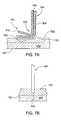
- FIGS. 7A-Bare partial sectional views of the media pack adhered to the top panel in alternative configurations
- FIGS. 8A-Bare sectional and top views of another embodiment of the media pack adhered to the top panel
- FIGS. 9A-Bare sectional and top views of another embodiment of the media pack adhered to the top panel
- FIG. 10is another embodiment of a media pack adhered to a top panel
- FIG. 11is an exploded view of a conventionally-pleated media pack of a filter having a conventionally-pleated media pack sealed to a frame using a swirled adhesive;
- FIG. 12is another embodiment of a filter having a conventionally-pleated media pack sealed to a housing with a swirled adhesive
- FIG. 13is another embodiment of the filter having a swirled adhesive utilized to seal a plurality of filter banks.
- FIG. 14is a flow diagram of one embodiment of a method for fabricating an air filter.
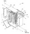
- FIGS. 1A-Bare front isometric and exploded views of one embodiment of an air filter assembly 100 of the present invention.
- the filter assembly 100 illustrated in FIGS. 1A-Bincorporate a plurality of beneficial features, it is contemplated that the invention may be beneficially incorporated in other filter assemblies having different configurations.
- the filter assembly 100includes a frame assembly 102 and a media pack 104 .
- the media pack 104is coupled to the frame assembly 102 such that substantially all of the air passing through the filter assembly 100 will pass through the media pack 104 .
- the media pack 104is fabricated from a continuous, uninterrupted sheet of filter media 106 having both backs of minipleated regions 108 arranged in a non linear orientation, for example, in one or more macropleats, or v-banks 110 , advantageously providing both economy of fabrication and high media area for efficient filtration.
- the use of a single media pack 104 in the filter assembly 100 fabricated from a single continuous, uninterrupted sheet of filter media 106eliminates the labor, materials and logistics associated with cutting, storing, assembling and sealing multiple media packs into a single filter element.
- the filter media 106 in the minipleated regions 108is generally folded in an accordion-like manner to form a plurality of minipleats 120 .
- the minipleats 120may have a pleat height 112 of about 1 to about 3 inches, and a minipleat density of about 0.75 to about 1.5 pleats per inch (as shown in FIG. 1C ).
- the minipleat pleats 120may optionally have minipleat separators (not shown) disposed on one or more sides of the pleats 120 .
- the minipleat separatorsmay be thread, ribbon or hot melt, as known in the art.
- Adjacent minipleated regions 108are also folded in an accordion-like manner to define each v-bank 110 .
- the v-banks 110may have a pleat height 116 of about 5.0 to about 15.0 inches.
- the v-banks 110may have a density of about 0.16 to about 0.33 v-banks per inch (as shown in FIG. 1D ).
- the edges of the minipleated region 108 and v-banks 110 having the accordion like folds that are generally referred to as open edges 142 , while the opposing short ends of the media pack 104are generally referred to as the flat edge 144 . It is contemplated that other v-bank configurations may be utilized. In the embodiment depicted in FIGS. 1A-1B , the media pack 104 has two v-banks 110 . Other common configurations include one or two v-banks 110 , although other configurations are contemplated.
- a bank separator 122may be disposed between the minipleat regions 108 forming the v-banks 110 .
- the bank separators 122may be disposed on the upstream and/or downstream side of the filter assembly 100 . In the embodiment depicted in FIGS. 1A-B , two bank separators 122 are shown on the downstream side of the filter assembly 100 with no bank separators utilized on the upstream side.
- the bank separator 122generally includes a channel 124 and a finger form 126 .
- the channel 124couples the finger form 126 to the frame assembly 102 .
- the finger form 126generally includes a plurality of center fingers 128 and edge fingers 130 .
- the center fingers 128extend from the channel 124 between facing sides of adjacent minipleated regions 108 .
- the edge fingers 130are shorter than the center fingers 128 and extend from the channel 124 between the frame assembly 102 and the adjacent minipleated region 108 .
- FIG. 2depicts an exploded isometric view of one embodiment of the bank separator 122 .
- the channel 124has a c-sectional form and may be fabricated from metal, glass reinforced plastic (FRP) or other suitable material.
- a hole 202is provided in each end 204 of the channel 124 to facilitate coupling the channel 124 to the frame assembly 102 , for example, by a fastener, such as a rivet or screw.
- the finger form 126is generally fabricated from metal, cardboard, wood, chipboard, paperboard, FRP, plastic or other suitable material.
- a base 206 of the finger form 126is sized to slide into and be retained by the channel 126 .
- the center and edge fingers 128 , 130may be fabricated with the base 206 as a one-piece assembly, for example, by stamping from a single blank stock of material.
- the finger form 126has a length substantially equal to that of the channel 126 .
- edges 208 of the finger form 126align with the ends 204 of the channel 124 , thereby orientating the fingers 128 , 130 along the channel 126 in a predetermined position.
- the edge 208is shown on the base 206 , the edge 208 may additionally or alternatively be defined by the outside of the edge fingers 130 .
- a notch 210is formed in at least one of the edge fingers 130 or base 206 on the side of the finger form 126 facing away from the fingers 128 , 130 .
- the notch 210is aligned with the hole 202 formed in the channel 124 .
- the notch 210provides clearance for the fastener passing through the hole 202 utilized to secure the channel 126 of bank separator 122 to the frame assembly 102 without disturbing the positioning of the finger form 126 relative to the channel 124 .
- FIG. 3depicts one embodiment of the filter media 106 suitable for using in the media pack 104 .
- the filter media 106generally has a stiffness suitable to substantially maintain the pleat configuration when subjected to air flow rates of at least about 88 feet per minute. Flow rates through the filter assembly 100 may range between, but are not limited to, about 750 to about 3000 cubic feet per minute.
- the filter media 106has a filtering layer 302 and a backing layer 304 .
- the filtering layer 302may be fabricated from glass fiber, wet laid glass fiber, synthetic media, or organic material, such a cellulose or cotton, among others.
- the filtering layer 302is generally selected to provide a predetermined filtering efficiency and pressure drop.
- the filtering layer 302typically has, but is not limited to, an efficiency of up to about 95 percent DOP. In another embodiment, a filtering efficiency may be selected in the range of about 9 to about 14 MERV, such as about 10 to about 13 MERV. It is contemplated that media providing either higher or lower filtering efficiencies may be utilized.
- the backing layer 304provides support to the filtering layer 302 and is typically located on the downstream side of the filtering layer 302 .
- the backing layer 304may be a mesh, mat, perforated, expanded or other material suitable for supporting the filtering layer 302 without detrimentally increasing the pressure drop across the media 106 .
- the backing layer 304may be fabricated from a metal, polymeric or other suitable material.
- the backing layer 304is a wire mesh 306 .
- the wire mesh 306is fabricated from copper clad wire arranged in a square grid having one inch welded centers.
- a minipleat fold radius between pleats 120 in the minipleat region 108is generally maintained at a radius of at least about 0.090 inches to ensure the filtering layer 302 is not sharply bent in a manner that could potentially leakage and/or lead to shedding of the filtering media.
- a width of the filtering layer 302is generally greater than the width of the backing layer 304 .
- a lateral edge 310 of the filtering layer 302extends beyond a lateral edge (shown as dashed line 312 ) of the backing layer 304 to define an unsupported edge region 350 of the filtering layer 304 .
- Respective terminal ends 314 , 316 of the filtering and backing layers 302 , 304are generally aligned and are located along the first edge 144 after pleating.
- the frame assembly 102generally has a quadrilateral form, such as square or rectangular.
- the frame assembly 102includes top and bottom panels 132 , 134 coupled to side panels 136 .
- the panels 132 , 134 , 136may be fabricated from metal, coated steel, galvanized steel, plastic, wood or wood product such as fiber board, cardboard, chip board and the like, FRP or other suitable material.
- the panels 132 , 134 , 136may be coupled by any suitable method, for example, by clips, screws, rivets, welding, snap-fit, adhesive and tape, among others. In the embodiment depicted in FIGS.
- FIGS. 1A-Bdepict the panels 132 , 134 , 136 as separately fabricated components, it is contemplated that two or more, or even all of the panels 132 , 134 , 136 , may be fabricated from a single blank of base material or be a molded assembly.
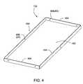
- FIG. 4depicts an isometric view of one embodiment of the top panel 132 .
- the bottom panel 134may be similarly constructed.
- the top panel 132generally includes a wall 402 having a plurality of flanges 404 extending therefrom.
- the flanges 404include a plurality of panel mounting holes 406 for accepting the rivet 138 utilized to secure the top panel 132 to the side panels 136 .
- Each of the flanges 404may optionally include appropriate brace mounting holes 408 to facilitate coupling braces 140 between the panels 132 , 136 .
- the top panel 132is fabricated from sheet metal.
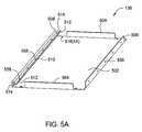
- FIGS. 5A-Care isometric, sectional and partial side views of one embodiment of the side panel 136 .
- the side panel 136generally includes a wall 502 having opposing end flanges 504 , a downstream flange 506 and an upstream flange 508 extending therefrom.
- the wall 502includes a plurality of panel mounting holes 518 for accepting the rivet 138 utilized to secure the side panels 136 to the top and bottom panels 132 , 134 .
- Each of the flanges 506 , 508may optionally include appropriate brace mounting holes 556 for facilitating coupling braces 140 between the panels 132 , 134 , 136 .
- the flanges 506 , 508may optionally include additional holes 558 for securing the filter assembly 100 to a holding flange, second filter or other object.
- the top panel 132is fabricated from sheet metal.
- An anchor tab 510is provided adjacent the upstream flange 508 .
- the anchor tab 510provides a surface for attaching the flat edge 144 of the media pack 104 to the frame assembly 102 .
- the anchor tab 510extends inward relative to the wall 502 and away from the upstream flange 508 .
- the anchor tab 510is spaced from the upstream flange 508 a distance of about 0.25 to about 10 inches, thereby spacing the media pack 104 from the wall 502 .
- the spacing of the media pack 104 from the wall 504enhances air flow and reduces pressure drop by providing adequate open area between the media pack 104 and wall 502 proximate the upstream flange 508 so that the proximity of the pack 104 to the wall 502 does not restrict the flow of air in that area.
- the anchor tab 510may be orientated between zero to about 90 degrees relative to the upstream flange 508 . In one embodiment, the anchor tab 510 is orientated between 30 to about 60 degrees relative to the upstream flange 508 . From another reference point, the orientation of the anchor tab 510 is between about parallel to about perpendicular relative to the wall 502 . In one embodiment, the anchor tab 510 is orientated between 30 to about 60 degrees relative to the wall 502 . In the embodiment, the anchor tab 510 extends further away from the wall 502 than the upstream flange 508 . In the embodiment depicted in FIGS. 5A-C , the anchor tab 510 extends at least about 1 inch from the wall 502 , although shorter lengths may alternatively be used.
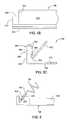
- FIG. 6is a sectional view of the side panel 136 illustrating the attachment of the media pack 104 to the anchor tab 510 .
- the flat edge 144 of the media pack 104is coupled to the anchor tab 510 by an adhesive 602 .
- the adhesive 602may be a pressure sensitive adhesive, a double sided tape, a silicone adhesive, a polyurethane adhesive or other suitable adhesive. In the embodiment depicted in FIG. 6 , the adhesive 602 is a hot melt.
- the adhesive 602may be disposed along the anchor tab 510 in a substantially uninterrupted bead, covering the entire length, or intermittently.
- the flat edge 144 of the media pack 104may be potted or adhered in a trough 604 defined between the anchor tab 510 and the upstream flange 508 .
- the flat edge 144 of the media pack 104may be clamped between the anchor tab 510 and the wall 502 , or secured to the side panel 136 using a spring clip.
- the length of the anchor tab 510is generally less than a length of the upstream flange 508 .
- an end 512 of the anchor tab 510is offset inward from an end 514 of the upstream flange 508 relative to the end flanges 504 .
- the recessed ends 512 of the anchor tab 510is thus maintained spaced-apart from the walls 402 of the top and bottom panels 132 , 134 , thereby providing clearance for the open end 142 of the media pack 104 to sealingly engage the top and bottom panels 132 , 134 as described with reference to FIG. 7A .
- the anchor tab 510may be part of, or coupled to the side panel 136 .
- the anchor tab 510is fabricated from the portion of the side panel 136 forming the upstream flange 508 .
- the upstream flange 508includes an outer wall 550 and an inner wall 552 .
- the outer wall 550is coupled along a first side to the wall 502 .
- the second side of the outer wall 550terminates at a fold, which beings the inner wall 552 .
- the inner wall 552extends back towards the wall 502 to a bend 554 .
- the anchor tab 510extends back away from the inner wall 552 and wall 502 as discussed above.
- the holes 556 , 558 formed through the upstream flange 508include a first hole 562 formed through the outerwall 550 and a second hole 564 formed through the inner wall 564 .
- the second hole 564is typically larger in diameter than the first hole 562 to ensure alignment between the holes 562 , 564 forming the hole 556 for the rivet or other fastener securing the braces 140 and/or bank separators 122 .
- the angle of the anchor tab 510(and/or spacing of the anchor tab 510 provided by the bend 554 /trough 602 ) allows the insertion of a fastener through the holes 552 , 558 without obstruction.
- FIG. 7Ais a partial sectional view of the media pack 104 adhered to the top panel 132 .
- the media pack 104is adhered to the bottom panel 134 in a similar manner.
- the open end 142 of the media pack 104is sealed to the top panel 132 using an adhesive 702 .
- the method of how the adhesive is utilizedwill depend on the amount of bypass leakage permissible under the specification under which the filter assembly 100 is built and/or tested.
- the adhesive 702substantially covers the inner surface of the wall 402 .
- the adhesive 702may be a polymer-based adhesive, a water soluble paste, a hot melt adhesive, or other suitable adhesive.
- the adhesive 702is a pressure sensitive hot melt adhesive, such as semi-crystalline adhesives, polyolefin-based adhesives, polyimide-based adhesives, modified EVA adhesives and (APAO) amorphous polyolefins.
- suitable adhesivesinclude (SIS) styrene isoprene styrene, rubber-based adhesives and acrylic-based adhesives, among others.
- Other suitable adhesivesmay be water-based pastes, including thixotropic, paste and liquid adhesive systems.
- Additional adhesivesmay be mastics, caulks and the like, including latex, silicone, polyurethane, pitel and tar, among others.
- the adhesivemay alternatively be a two component or reacted thermoset material, such as epoxy, polyurethane, or a heat-cured material, such as plastisols.
- the adhesivemay also be a solvent or water-based contact cement, rubber cement and the like.
- the adhesive 702is a pressure sensitive repositionable adhesive containing an oily component resulting in a tacky material with a relatively long open time (approximately one minute) and an aggressive bond that allows the open end 144 to be adjusted. (i.e., repositioned) relative to the wall 402 .
- Repositionable adhesivesgenerally have an open time (e.g., time in which good bonding will occur) of at least about 10 seconds. The open time may exceed about 1 minute, or be indefinite.
- the use of a repositionable adhesiveis beneficial in that the orientation between opposing minipleated regions 108 forming the v-banks 140 may be set with greater position. It has been demonstrated that a symmetric and uniform orientation of the v-banks 140 enhances airflow uniformity through the filter assembly, and thus, minimizes the pressure drop across the filter assembly during operation.
- the filter assembly 100 with uniform bank spacinghas a resistance of about 0.49 inches water gage (in. wg.) as compared to a resistance of about 0.58 in. wg. for a similar filter fabricated with non-repositional adhesives which resulted in non-uniform bank spacing.
- the adhesive 702has a high tack that is sufficient to anchor the media pack 104 to the side panels 136 over the course of normal operations.
- the adhesive 702may have a moderate to aggressive tack, and may bond substantially instantaneously to the media pack 104 .
- Suitable adhesivesmay be of the type that exhibit excellent adhesion to a wide variety of materials, including the media pack 104 and the frame material.
- FIG. 7Bis another partial sectional view of the media pack 104 adhered to the top panel 132 .
- the open end 142 of the media pack 104is also sealed to the top panel 132 using an adhesive 712 having a sufficient depth to allow the open end 142 to penetrate the adhesive 712 .
- the seal between the media 106 and the adhesive 712provides the primary barrier to air leakage.
- FIG. 8A-Bare sectional and top views of another embodiment of the media pack 104 adhered to the top panel 132 .
- An adhesive 812is disposed on the wall 402 in a discontinuous configuration, for example, by utilizing a spray or swirl pattern such that the adhesive 812 does not continuously cover the wall 402 .
- the swirl patternmay be described as one or more elongated adhesive beads or strings.
- the swirl patternmay have a random, wave, oscillating, a swirl or other pattern across the wall 402 .
- the swirl patternmay also have adhesive regions touching and spaced from each other.
- the adhesive 812is a hot melt suitable for use with a swirl gun, such as hot melt adhesives described above with reference to adhesive 712 .
- a hot melt swirl spray gunavailable from Nordson Corporation, located in Westlake, Ohio.
- less than about 50 grams/square foot of adhesivemay be utilized to effectively secure the media pack 104 to the wall 402 , as compared to about 70 grams/square foot in conventional applications.
- less than about 20 grams/square foot of adhesivemay be utilized to effectively secure the media pack 104 . It is contemplated that the grams/square foot of adhesive utilized may be further reduced by foaming the adhesive.
- adhesive systemssuch as two component or reacted systems, epoxies, polyurethanes, thirstropic, caulk or other adhesive may be utilized in a swirl or other pattern that minimizes adhesive use while suitably bonding the media pack to the wall 402 .
- FIGS. 9A-Bare sectional and top views of another embodiment of the media pack 104 adhered to the top panel 132 .
- the adhesive 812is disposed in an accordion-like or zig-zag manner such that a patter 902 of adhesive disposed on the wall 402 is substantially aligned with the v-banks 110 of the media pack 104 . It is contemplated that continuous layer (i.e., not swirled) of a non-flowing adhesive may be utilized.
- the adhesive 802may be applied using a mask 1002 , as shown in FIG. 10 .
- the mask 1002may be used as a guide or pattern to direct the motion of the spray gun.
- the mask 1002may be used as a stencil.
- the mask 1002may be a polymeric material, such as polyethylene, which does not adhere to the adhesive 802 .
- the adhesive overspray 1004 disposed on the mask 1002may be periodically peeled off, re-melted and re-sprayed onto the wall 402 .
- the spray adhesivemay additionally be applied robotically to ensure uniform adhesive coverage.
- swirl adhesive 1102may be applied to a frame 1104 to seal a conventionally pleated media pack 1106 in the fabrication of a panel filter 1100 , as shown in FIG. 11 .
- swirl adhesive 1202may be applied to a flat portion 1208 of a frame 1204 to form a strip 1206 that is narrower than the width of the flat portion 1208 .
- the width of the strip 1206is selected to adequately seal a conventionally pleated media pack 1210 in the fabrication of a panel filter 1200 , as shown in FIG. 12 .
- the strip 1206may be applied using a mask, as discussed above.
- a strip 1302 of adhesive 1304may be applied on a frame 1308 in a zig-zag pattern to seal a plurality of filter banks 1306 arranged in a v-bank configuration 1310 in the fabrication of a v-bank filter 1300 , as shown in FIG. 13 .
- FIG. 14is one embodiment of a method 1400 for making filter assembly.
- the method 1400begins at step 1402 by securing the flat ends of a continuous pleated media pack to a side panel of a filter frame assembly.
- the flat endsby be secured to an anchor tab extending from the panel using a lap joint using a hot melt or other suitable adhesive.
- a filter securing adhesiveis applied to the top and bottom panels of the filter frame assembly.
- the adhesivemay be disposed across the entire area of the top and bottom panels.
- the adhesivemay be arranged one the top and bottom panels in an accordion configuration.
- the adhesiveis applied in an interrupted strip.
- the adhesiveis applied using a swirl gun to produce a swirled adhesive pattern.
- the adhesiveis foamed. It is contemplated that the adhesive may be applied using any combination of the above configurations.
- the open end of the pleated media packis brought into contact with the adhesive disposed in top and bottom panels of the filter frame assembly.
- the pleated media packis arranged in an accordion configuration to define one or more v-banks prior to adhering to the top and bottom panels of the frame assembly.
- the entire length of the pleated media packis maintained in a linear relationship while adhered to the top and bottom panels.
- the separatorsare installed. Braces are secured between the side and top/bottom panels at step 1410 to rigiditize the filter assembly.
- a filter assemblyhas been provided that facilitates rapid assembly with minimal labor.
- embodiment of the filter assembly described hereinmay be fabricated with less materials than conventional designs.
- the filter assembly of the present inventionhas demonstrated performance comparable to conventional designs, thus making the invention well positioned to address the needs of next generation filtration products.
Landscapes
- Chemical & Material Sciences (AREA)
- Chemical Kinetics & Catalysis (AREA)
- Filtering Of Dispersed Particles In Gases (AREA)
Abstract
Description
Claims (20)
Priority Applications (1)
| Application Number | Priority Date | Filing Date | Title |
|---|---|---|---|
| US11/365,571US7931726B2 (en) | 2006-03-01 | 2006-03-01 | Box-V filter and method of fabricating the same |
Applications Claiming Priority (1)
| Application Number | Priority Date | Filing Date | Title |
|---|---|---|---|
| US11/365,571US7931726B2 (en) | 2006-03-01 | 2006-03-01 | Box-V filter and method of fabricating the same |
Publications (2)
| Publication Number | Publication Date |
|---|---|
| US20070204579A1 US20070204579A1 (en) | 2007-09-06 |
| US7931726B2true US7931726B2 (en) | 2011-04-26 |
Family
ID=38470278
Family Applications (1)
| Application Number | Title | Priority Date | Filing Date |
|---|---|---|---|
| US11/365,571Expired - Fee RelatedUS7931726B2 (en) | 2006-03-01 | 2006-03-01 | Box-V filter and method of fabricating the same |
Country Status (1)
| Country | Link |
|---|---|
| US (1) | US7931726B2 (en) |
Cited By (13)
| Publication number | Priority date | Publication date | Assignee | Title |
|---|---|---|---|---|
| US20110265436A1 (en)* | 2010-04-30 | 2011-11-03 | Keith Platt | Three-Dimensional Filter |
| US20120005997A1 (en)* | 2010-07-07 | 2012-01-12 | General Electric Company | Pleated walled bag filters for gas turbine inlet systems |
| US20120031059A1 (en)* | 2010-08-04 | 2012-02-09 | Haslebacher William J | Filter assembly with improved gasket |
| WO2014058692A1 (en)* | 2012-10-09 | 2014-04-17 | W.L. Gore & Associates, Inc. | Improved v-panel filter |
| US20140137524A1 (en)* | 2012-11-19 | 2014-05-22 | Bha Altair, Llc | Reverse v-cell or minipleat filter with pleat pack mechanically sealed |
| US20140298764A1 (en)* | 2013-04-05 | 2014-10-09 | Columbus Industries, Inc. | Industrial coating application filter with pleated support |
| US20150135665A1 (en)* | 2012-05-15 | 2015-05-21 | Mann+Hummel Gmbh | Cabin Air Filter and Filter Element for a Cabin Air Filter |
| US20170056800A1 (en)* | 2015-05-05 | 2017-03-02 | Airgle Corporation | Filter assembly for providing purified air |
| US9764266B1 (en)* | 2013-03-13 | 2017-09-19 | Scott Carter | Modular air filter housing |
| US10486094B2 (en) | 2015-05-15 | 2019-11-26 | 3M Innovative Properties Company | Collapsable V-bank filter |
| US11415339B2 (en) | 2017-05-30 | 2022-08-16 | Johnson Controls Tyco IP Holdings LLP | HVAC filter locking systems and methods |
| US11511221B2 (en)* | 2015-10-30 | 2022-11-29 | Dräger Safety AG & Co. KGaA | Particle filter as well as method for the manufacture thereof |
| US11672882B1 (en) | 2020-06-21 | 2023-06-13 | Proair, Llc | Air treatment system for vehicles |
Families Citing this family (12)
| Publication number | Priority date | Publication date | Assignee | Title |
|---|---|---|---|---|
| EP1671693A3 (en)* | 2004-12-07 | 2009-02-18 | National Starch and Chemical Investment Holding Corporation | Filter and method of making said filter |
| US8425644B2 (en) | 2008-01-31 | 2013-04-23 | Anders Sundvik | High flow V-bank filter |
| US9043989B2 (en)* | 2008-06-04 | 2015-06-02 | Camfil Usa, Inc. | Method and apparatus for providing clean air to animal enclosures |
| US8764870B2 (en) | 2010-09-16 | 2014-07-01 | Cummins Filtration Ip, Inc. | V-shaped filter and fixture |
| US8720028B2 (en) | 2011-05-23 | 2014-05-13 | Bha Altair, Llc | Replaceable filter media and holding mechanism |
| US8926725B2 (en) | 2012-07-31 | 2015-01-06 | Cummins Filtration Ip, Inc. | V-shaped filter with serviceable frames and cartridges |
| JP6779275B2 (en) | 2015-07-15 | 2020-11-04 | ボールドウィン・フィルターズ・インコーポレーテッドBaldwin Filters Inc | Multi-component holding assembly for multi-panel air filters |
| US10369508B2 (en) | 2017-02-23 | 2019-08-06 | Baldwin Filters, Inc. | Filter with shield features |
| US12168193B2 (en) | 2015-07-15 | 2024-12-17 | Baldwin Filters, Inc. | Filter with shield features |
| US20180111079A1 (en)* | 2016-10-24 | 2018-04-26 | Baldwin Filters, Inc. | Air Filter with Outlet Receiver and Housing Assembly Incorporating Same |
| US20220314151A1 (en)* | 2021-04-06 | 2022-10-06 | K&N Engineering, Inc. | Multi-panel air filter |
| TW202348300A (en) | 2022-03-19 | 2023-12-16 | 印度商艾羅菲爾過濾器印度私人有限公司 | Mini-pleat v cell filter |
Citations (34)
| Publication number | Priority date | Publication date | Assignee | Title |
|---|---|---|---|---|
| US3490211A (en)* | 1967-07-31 | 1970-01-20 | Keystone Filter Media Co | High efficiency particulate air filter |
| US4610706A (en) | 1983-02-03 | 1986-09-09 | Nesher Alexander G | HEPA filter with integral separators |
| US4701197A (en)* | 1986-10-07 | 1987-10-20 | Allied Corp. | Molded panel filter |
| US5098767A (en)* | 1989-02-15 | 1992-03-24 | Pall Corporation | Filter device with micropleats and macropleats |
| US5106397A (en) | 1990-12-26 | 1992-04-21 | Ford Motor Company | Air cleaner/noise silencer assembly |
| US5593529A (en) | 1990-01-18 | 1997-01-14 | Pall Corporation | Cylindrical filters and their manufacture |
| US5674303A (en) | 1996-01-16 | 1997-10-07 | Ter Horst; Dirk Dieter Hans | Filter assembly |
| US5779747A (en) | 1995-08-04 | 1998-07-14 | Firma Carl Freudenberg | Flexible folded filter insert |
| US6074450A (en)* | 1996-10-15 | 2000-06-13 | Raber; Robert R. | Air filter assembly |
| US6171354B1 (en) | 1998-10-13 | 2001-01-09 | S. C. Johnson & Son, Inc. | Self-adhesive air filter for forced air climate control system |
| US6319300B1 (en)* | 2000-07-12 | 2001-11-20 | Liou-Win Chen | Filter assembly of an air filter |
| US6375699B1 (en)* | 1997-10-17 | 2002-04-23 | 3M Innovative Properties Company | Injection mold for insert-molding a synthetic material around a filter material, filter for the filtration of fluids and method for producing such filter |
| US20020083836A1 (en)* | 2000-12-28 | 2002-07-04 | Yoshiyuki Doi | Gas turbine suction air filter, a gas turbine using the same and a method for using the same |
| US20020119722A1 (en) | 2000-05-15 | 2002-08-29 | Welch Howard M. | Elastic stranded laminate with adhesive bonds and method of manufacture |
| US6447566B1 (en)* | 2000-06-21 | 2002-09-10 | Freudenberg Nonwovens Limited Partnership | Air filtration system with recessed filter and edge banding |
| US6485538B1 (en)* | 1999-03-31 | 2002-11-26 | Yugen Caisha Infinity Kenkyusho | Air-conditioning air filter |
| US20030056479A1 (en)* | 2001-09-25 | 2003-03-27 | Lemaster Harley | Self pleating filter media |
| US6740136B2 (en)* | 2001-10-12 | 2004-05-25 | 3M Innovative Properties Company | Interconnected filter frame and filter framing method |
| US6743274B2 (en) | 2001-01-24 | 2004-06-01 | Toyoda Boshoku Corporation | Filter and production method thereof |
| US6758877B2 (en) | 2001-03-13 | 2004-07-06 | Toyoda Boshoku Corporation | Filter and method for manufacturing the filter |
| US6814773B2 (en)* | 2001-10-09 | 2004-11-09 | Carrier Corporation | Expandable media filter assembly |
| US6833017B2 (en)* | 2001-08-10 | 2004-12-21 | Spx Corporation | Filter assembly and method with polyimide |
| US6863959B2 (en) | 2000-12-22 | 2005-03-08 | Kimberly-Clark Worldwide, Inc. | Laminate and web characteristic control by varying bonding patterns |
| US20050144916A1 (en)* | 2003-10-14 | 2005-07-07 | Adamek Daniel E. | Filter assembly with pleated media V-packs, and methods |
| US7004989B2 (en)* | 2003-08-22 | 2006-02-28 | Camfil Farr, Inc. | Filter assembly with compressed media edge seal |
| US7048501B2 (en)* | 2001-11-21 | 2006-05-23 | Mitsubishi Heavy Industries, Ltd. | Dust collecting filter, dust collecting device, and air intake device for gas turbine |
| US7148501B1 (en)* | 2005-12-28 | 2006-12-12 | Eastman Kodak Company | Storage phosphor reader having frame vibration isolation and frame locking |
| US7156898B2 (en)* | 2002-07-12 | 2007-01-02 | Jaisinghani Rajan A | Low pressure drop deep electrically enhanced filter |
| US7255723B2 (en)* | 2004-01-09 | 2007-08-14 | Aaf Mcquay, Inc. | Crest supported filter frame assembly and method |
| US7261818B1 (en) | 2000-03-24 | 2007-08-28 | Camfil Ab | Method for the fabrication of a pleated filter |
| US20070209343A1 (en)* | 2006-03-09 | 2007-09-13 | Leon Robert Cuvelier | Filter assembly with pleated media pockets, and methods |
| US7377963B2 (en)* | 2004-03-30 | 2008-05-27 | Nichias Corporation | Adsorption filter and manufacturing method thereof |
| US7425226B2 (en)* | 2005-05-12 | 2008-09-16 | Powell Allan R | Fluid filter with canted fanfold pleats |
| US7481862B2 (en)* | 2005-06-09 | 2009-01-27 | Purolator Filters Na Llc | Filter assembly using adhesive center tube |
- 2006
- 2006-03-01USUS11/365,571patent/US7931726B2/ennot_activeExpired - Fee Related
Patent Citations (35)
| Publication number | Priority date | Publication date | Assignee | Title |
|---|---|---|---|---|
| US3490211A (en)* | 1967-07-31 | 1970-01-20 | Keystone Filter Media Co | High efficiency particulate air filter |
| US4610706A (en) | 1983-02-03 | 1986-09-09 | Nesher Alexander G | HEPA filter with integral separators |
| US4701197A (en)* | 1986-10-07 | 1987-10-20 | Allied Corp. | Molded panel filter |
| US5098767A (en)* | 1989-02-15 | 1992-03-24 | Pall Corporation | Filter device with micropleats and macropleats |
| US5593529A (en) | 1990-01-18 | 1997-01-14 | Pall Corporation | Cylindrical filters and their manufacture |
| US5106397A (en) | 1990-12-26 | 1992-04-21 | Ford Motor Company | Air cleaner/noise silencer assembly |
| US5779747A (en) | 1995-08-04 | 1998-07-14 | Firma Carl Freudenberg | Flexible folded filter insert |
| US5674303A (en) | 1996-01-16 | 1997-10-07 | Ter Horst; Dirk Dieter Hans | Filter assembly |
| US6074450A (en)* | 1996-10-15 | 2000-06-13 | Raber; Robert R. | Air filter assembly |
| US6375699B1 (en)* | 1997-10-17 | 2002-04-23 | 3M Innovative Properties Company | Injection mold for insert-molding a synthetic material around a filter material, filter for the filtration of fluids and method for producing such filter |
| US6171354B1 (en) | 1998-10-13 | 2001-01-09 | S. C. Johnson & Son, Inc. | Self-adhesive air filter for forced air climate control system |
| US6485538B1 (en)* | 1999-03-31 | 2002-11-26 | Yugen Caisha Infinity Kenkyusho | Air-conditioning air filter |
| US7261818B1 (en) | 2000-03-24 | 2007-08-28 | Camfil Ab | Method for the fabrication of a pleated filter |
| US20020119722A1 (en) | 2000-05-15 | 2002-08-29 | Welch Howard M. | Elastic stranded laminate with adhesive bonds and method of manufacture |
| US6447566B1 (en)* | 2000-06-21 | 2002-09-10 | Freudenberg Nonwovens Limited Partnership | Air filtration system with recessed filter and edge banding |
| US6319300B1 (en)* | 2000-07-12 | 2001-11-20 | Liou-Win Chen | Filter assembly of an air filter |
| US6863959B2 (en) | 2000-12-22 | 2005-03-08 | Kimberly-Clark Worldwide, Inc. | Laminate and web characteristic control by varying bonding patterns |
| US20020083836A1 (en)* | 2000-12-28 | 2002-07-04 | Yoshiyuki Doi | Gas turbine suction air filter, a gas turbine using the same and a method for using the same |
| US6602328B2 (en)* | 2000-12-28 | 2003-08-05 | Mitsubishi Heavy Industries, Ltd. | Gas turbine suction air filter, a gas turbine using the same and a method for using the same |
| US6743274B2 (en) | 2001-01-24 | 2004-06-01 | Toyoda Boshoku Corporation | Filter and production method thereof |
| US6758877B2 (en) | 2001-03-13 | 2004-07-06 | Toyoda Boshoku Corporation | Filter and method for manufacturing the filter |
| US6833017B2 (en)* | 2001-08-10 | 2004-12-21 | Spx Corporation | Filter assembly and method with polyimide |
| US20030056479A1 (en)* | 2001-09-25 | 2003-03-27 | Lemaster Harley | Self pleating filter media |
| US6814773B2 (en)* | 2001-10-09 | 2004-11-09 | Carrier Corporation | Expandable media filter assembly |
| US6740136B2 (en)* | 2001-10-12 | 2004-05-25 | 3M Innovative Properties Company | Interconnected filter frame and filter framing method |
| US7048501B2 (en)* | 2001-11-21 | 2006-05-23 | Mitsubishi Heavy Industries, Ltd. | Dust collecting filter, dust collecting device, and air intake device for gas turbine |
| US7156898B2 (en)* | 2002-07-12 | 2007-01-02 | Jaisinghani Rajan A | Low pressure drop deep electrically enhanced filter |
| US7004989B2 (en)* | 2003-08-22 | 2006-02-28 | Camfil Farr, Inc. | Filter assembly with compressed media edge seal |
| US20050144916A1 (en)* | 2003-10-14 | 2005-07-07 | Adamek Daniel E. | Filter assembly with pleated media V-packs, and methods |
| US7255723B2 (en)* | 2004-01-09 | 2007-08-14 | Aaf Mcquay, Inc. | Crest supported filter frame assembly and method |
| US7377963B2 (en)* | 2004-03-30 | 2008-05-27 | Nichias Corporation | Adsorption filter and manufacturing method thereof |
| US7425226B2 (en)* | 2005-05-12 | 2008-09-16 | Powell Allan R | Fluid filter with canted fanfold pleats |
| US7481862B2 (en)* | 2005-06-09 | 2009-01-27 | Purolator Filters Na Llc | Filter assembly using adhesive center tube |
| US7148501B1 (en)* | 2005-12-28 | 2006-12-12 | Eastman Kodak Company | Storage phosphor reader having frame vibration isolation and frame locking |
| US20070209343A1 (en)* | 2006-03-09 | 2007-09-13 | Leon Robert Cuvelier | Filter assembly with pleated media pockets, and methods |
Non-Patent Citations (4)
| Title |
|---|
| Prosecution history of U.S. Appl. No. 11/365,326 as of May 29, 2009. |
| Prosecution history of U.S. Appl. No. 11/365,326 from May 29, 2009 to Mar. 15, 2011. |
| Prosecution history of U.S. Appl. No. 11/365,341 as of May 29, 2009. |
| Prosecution history of U.S. Appl. No. 11/365,341 from May 29, 2009 to Mar. 15, 2011. |
Cited By (23)
| Publication number | Priority date | Publication date | Assignee | Title |
|---|---|---|---|---|
| US20110265436A1 (en)* | 2010-04-30 | 2011-11-03 | Keith Platt | Three-Dimensional Filter |
| US8562708B2 (en)* | 2010-04-30 | 2013-10-22 | Diversitech Corporation | Three-dimensional filter |
| US20120005997A1 (en)* | 2010-07-07 | 2012-01-12 | General Electric Company | Pleated walled bag filters for gas turbine inlet systems |
| US8372181B2 (en)* | 2010-07-07 | 2013-02-12 | General Electric Company | Pleated walled bag filters for gas turbine inlet systems |
| US20120031059A1 (en)* | 2010-08-04 | 2012-02-09 | Haslebacher William J | Filter assembly with improved gasket |
| US8506666B2 (en)* | 2010-08-04 | 2013-08-13 | William J. Haslebacher | Filter assembly with improved gasket |
| US20150135665A1 (en)* | 2012-05-15 | 2015-05-21 | Mann+Hummel Gmbh | Cabin Air Filter and Filter Element for a Cabin Air Filter |
| US9630475B2 (en)* | 2012-05-15 | 2017-04-25 | Mann+Hummel Gmbh | Cabin air filter and filter element for a cabin air filter |
| US10513167B2 (en)* | 2012-05-15 | 2019-12-24 | Mann+Hummel Gmbh | Cabin air filter and filter element for a cabin air filter |
| US20170267069A1 (en)* | 2012-05-15 | 2017-09-21 | Mann+Hummel Gmbh | Cabin Air Filter and Filter Element for a Cabin Air Filter |
| WO2014058692A1 (en)* | 2012-10-09 | 2014-04-17 | W.L. Gore & Associates, Inc. | Improved v-panel filter |
| US9205359B2 (en) | 2012-10-09 | 2015-12-08 | W.L. Gore & Associates, Inc. | V-panel filters |
| US8852308B2 (en)* | 2012-11-19 | 2014-10-07 | Bha Altair, Llc | Reverse V-cell or minipleat filter with pleat pack mechanically sealed |
| US20140137524A1 (en)* | 2012-11-19 | 2014-05-22 | Bha Altair, Llc | Reverse v-cell or minipleat filter with pleat pack mechanically sealed |
| US9764266B1 (en)* | 2013-03-13 | 2017-09-19 | Scott Carter | Modular air filter housing |
| US9555358B2 (en)* | 2013-04-05 | 2017-01-31 | Columbus Industries, Inc. | Industrial coating application filter with pleated support |
| US20140298764A1 (en)* | 2013-04-05 | 2014-10-09 | Columbus Industries, Inc. | Industrial coating application filter with pleated support |
| US20170056800A1 (en)* | 2015-05-05 | 2017-03-02 | Airgle Corporation | Filter assembly for providing purified air |
| US10486094B2 (en) | 2015-05-15 | 2019-11-26 | 3M Innovative Properties Company | Collapsable V-bank filter |
| US11511221B2 (en)* | 2015-10-30 | 2022-11-29 | Dräger Safety AG & Co. KGaA | Particle filter as well as method for the manufacture thereof |
| US11415339B2 (en) | 2017-05-30 | 2022-08-16 | Johnson Controls Tyco IP Holdings LLP | HVAC filter locking systems and methods |
| US11965671B2 (en) | 2017-05-30 | 2024-04-23 | Tyco Fire & Security Gmbh | HVAC filter locking systems and methods |
| US11672882B1 (en) | 2020-06-21 | 2023-06-13 | Proair, Llc | Air treatment system for vehicles |
Also Published As
| Publication number | Publication date |
|---|---|
| US20070204579A1 (en) | 2007-09-06 |
Similar Documents
| Publication | Publication Date | Title |
|---|---|---|
| US7931726B2 (en) | Box-V filter and method of fabricating the same | |
| US7947101B2 (en) | Reduced adhesive filter assembly | |
| US7938927B2 (en) | Method of making a filter assembly | |
| US20230372854A1 (en) | Conformable pleated air filter with bridging filaments | |
| US8834611B1 (en) | Method for filtering air | |
| CA2778709C (en) | Framed air filter and method of making | |
| US8231700B2 (en) | Pleated filter with tridirectional scrim | |
| EP1778380B1 (en) | Method of forming self-supporting pleated filter media | |
| US20080067121A1 (en) | Fluid filter element with reinforcing scrim | |
| CA2413261C (en) | Air filtration system with recessed filter and edge banding | |
| US5858045A (en) | Multiple layer air filter media | |
| US6156089A (en) | Two-stage air filter with multiple-layer stage and post-filter stage | |
| CA2816256C (en) | Framed air filter with offset slot, and method of making | |
| US7537632B2 (en) | Panel filter with frame | |
| EP3563922B1 (en) | Air filter with tensile support member | |
| JP2786846B2 (en) | Foldable filter pack with flexibility in only one direction | |
| US8834592B1 (en) | Interlocking filtration system | |
| US7691165B1 (en) | Fluid filter frame system and method | |
| JPH06339611A (en) | Filter | |
| US20110154789A1 (en) | Method of Making a Marine Gas Turbine Filter | |
| WO2009156911A2 (en) | Air filter with integral inter-filter gap filler | |
| KR20100112583A (en) | Joined filter media pleat packs | |
| US20100263542A1 (en) | Frame flange attachable to a filter cartridge to form a filter assembly | |
| KR20170115163A (en) | Air filter apparatus | |
| US20250083172A1 (en) | Tapered Paint Filter |
Legal Events
| Date | Code | Title | Description |
|---|---|---|---|
| AS | Assignment | Owner name:CAMFIL AB, SWEDEN Free format text:ASSIGNMENT OF ASSIGNORS INTEREST;ASSIGNORS:KARLSSON, LENNART;SUNDVIK, ANDERS MARTIN;DEVINE, STEVEN T.;REEL/FRAME:017652/0507;SIGNING DATES FROM 20060228 TO 20060301 Owner name:CAMFIL AB, SWEDEN Free format text:ASSIGNMENT OF ASSIGNORS INTEREST;ASSIGNORS:KARLSSON, LENNART;SUNDVIK, ANDERS MARTIN;DEVINE, STEVEN T.;SIGNING DATES FROM 20060228 TO 20060301;REEL/FRAME:017652/0507 | |
| STCF | Information on status: patent grant | Free format text:PATENTED CASE | |
| FPAY | Fee payment | Year of fee payment:4 | |
| MAFP | Maintenance fee payment | Free format text:PAYMENT OF MAINTENANCE FEE, 8TH YEAR, LARGE ENTITY (ORIGINAL EVENT CODE: M1552); ENTITY STATUS OF PATENT OWNER: LARGE ENTITY Year of fee payment:8 | |
| AS | Assignment | Owner name:CAMFIL VENTURES AB, SWEDEN Free format text:CHANGE OF NAME;ASSIGNOR:CAMFIL AB;REEL/FRAME:061627/0395 Effective date:20220119 | |
| AS | Assignment | Owner name:CAMFIL AB, SWEDEN Free format text:ASSIGNMENT OF ASSIGNORS INTEREST;ASSIGNOR:CAMFIL VENTURES AB;REEL/FRAME:061768/0840 Effective date:20220718 | |
| FEPP | Fee payment procedure | Free format text:MAINTENANCE FEE REMINDER MAILED (ORIGINAL EVENT CODE: REM.); ENTITY STATUS OF PATENT OWNER: LARGE ENTITY | |
| LAPS | Lapse for failure to pay maintenance fees | Free format text:PATENT EXPIRED FOR FAILURE TO PAY MAINTENANCE FEES (ORIGINAL EVENT CODE: EXP.); ENTITY STATUS OF PATENT OWNER: LARGE ENTITY | |
| STCH | Information on status: patent discontinuation | Free format text:PATENT EXPIRED DUE TO NONPAYMENT OF MAINTENANCE FEES UNDER 37 CFR 1.362 | |
| FP | Lapsed due to failure to pay maintenance fee | Effective date:20230426 |