US7931688B2 - Expandable interbody fusion device - Google Patents
Expandable interbody fusion deviceDownload PDFInfo
- Publication number
- US7931688B2 US7931688B2US11/211,346US21134605AUS7931688B2US 7931688 B2US7931688 B2US 7931688B2US 21134605 AUS21134605 AUS 21134605AUS 7931688 B2US7931688 B2US 7931688B2
- Authority
- US
- United States
- Prior art keywords
- wafer
- plate
- expansion member
- lower plate
- fusion device
- Prior art date
- Legal status (The legal status is an assumption and is not a legal conclusion. Google has not performed a legal analysis and makes no representation as to the accuracy of the status listed.)
- Active, expires
Links
- 230000004927fusionEffects0.000titleclaimsabstractdescription28
- 238000007373indentationMethods0.000claimsdescription20
- 230000000295complement effectEffects0.000claimsdescription7
- 238000002513implantationMethods0.000claimsdescription5
- 235000012431wafersNutrition0.000abstractdescription272
- 238000003780insertionMethods0.000description70
- 230000037431insertionEffects0.000description70
- 230000013011matingEffects0.000description26
- 210000001519tissueAnatomy0.000description19
- 230000033001locomotionEffects0.000description14
- 210000000988bone and boneAnatomy0.000description9
- 238000000034methodMethods0.000description8
- 230000036316preloadEffects0.000description8
- 239000000463materialSubstances0.000description7
- 238000013459approachMethods0.000description4
- 230000008901benefitEffects0.000description4
- 230000001045lordotic effectEffects0.000description4
- 230000036961partial effectEffects0.000description4
- 238000001356surgical procedureMethods0.000description4
- 239000007943implantSubstances0.000description3
- 238000011065in-situ storageMethods0.000description3
- 210000004705lumbosacral regionAnatomy0.000description3
- 238000012986modificationMethods0.000description3
- 230000004048modificationEffects0.000description3
- 238000000926separation methodMethods0.000description3
- 230000006641stabilisationEffects0.000description3
- 238000011105stabilizationMethods0.000description3
- 208000008035Back PainDiseases0.000description2
- 208000008930Low Back PainDiseases0.000description2
- 239000004696Poly ether ether ketoneSubstances0.000description2
- 210000003484anatomyAnatomy0.000description2
- JUPQTSLXMOCDHR-UHFFFAOYSA-Nbenzene-1,4-diol;bis(4-fluorophenyl)methanoneChemical compoundOC1=CC=C(O)C=C1.C1=CC(F)=CC=C1C(=O)C1=CC=C(F)C=C1JUPQTSLXMOCDHR-UHFFFAOYSA-N0.000description2
- 239000012620biological materialSubstances0.000description2
- 230000003247decreasing effectEffects0.000description2
- 230000007246mechanismEffects0.000description2
- 229920002530polyetherether ketonePolymers0.000description2
- 230000008569processEffects0.000description2
- 230000002829reductive effectEffects0.000description2
- 230000002787reinforcementEffects0.000description2
- 230000004075alterationEffects0.000description1
- 208000037873arthrodesisDiseases0.000description1
- 238000005452bendingMethods0.000description1
- 239000000560biocompatible materialSubstances0.000description1
- 230000000740bleeding effectEffects0.000description1
- 239000000316bone substituteSubstances0.000description1
- 230000008859changeEffects0.000description1
- 238000000576coating methodMethods0.000description1
- 239000002131composite materialSubstances0.000description1
- 239000004020conductorSubstances0.000description1
- 238000010276constructionMethods0.000description1
- 238000007796conventional methodMethods0.000description1
- 230000007547defectEffects0.000description1
- 230000003412degenerative effectEffects0.000description1
- 238000006073displacement reactionMethods0.000description1
- 230000000694effectsEffects0.000description1
- 239000000284extractSubstances0.000description1
- 239000000945fillerSubstances0.000description1
- -1for exampleSubstances0.000description1
- 230000006872improvementEffects0.000description1
- 230000009545invasionEffects0.000description1
- 230000000921morphogenic effectEffects0.000description1
- 210000005036nerveAnatomy0.000description1
- 230000000278osteoconductive effectEffects0.000description1
- 230000002642osteogeneic effectEffects0.000description1
- 230000002138osteoinductive effectEffects0.000description1
- 238000007747platingMethods0.000description1
- 230000001737promoting effectEffects0.000description1
- 102000004169proteins and genesHuman genes0.000description1
- 108090000623proteins and genesProteins0.000description1
- 230000009467reductionEffects0.000description1
- 230000000284resting effectEffects0.000description1
- 230000000717retained effectEffects0.000description1
- 239000007787solidSubstances0.000description1
- 230000000087stabilizing effectEffects0.000description1
- 210000002536stromal cellAnatomy0.000description1
Images


Classifications
- A—HUMAN NECESSITIES
- A61—MEDICAL OR VETERINARY SCIENCE; HYGIENE
- A61F—FILTERS IMPLANTABLE INTO BLOOD VESSELS; PROSTHESES; DEVICES PROVIDING PATENCY TO, OR PREVENTING COLLAPSING OF, TUBULAR STRUCTURES OF THE BODY, e.g. STENTS; ORTHOPAEDIC, NURSING OR CONTRACEPTIVE DEVICES; FOMENTATION; TREATMENT OR PROTECTION OF EYES OR EARS; BANDAGES, DRESSINGS OR ABSORBENT PADS; FIRST-AID KITS
- A61F2/00—Filters implantable into blood vessels; Prostheses, i.e. artificial substitutes or replacements for parts of the body; Appliances for connecting them with the body; Devices providing patency to, or preventing collapsing of, tubular structures of the body, e.g. stents
- A61F2/02—Prostheses implantable into the body
- A61F2/30—Joints
- A61F2/44—Joints for the spine, e.g. vertebrae, spinal discs
- A61F2/4455—Joints for the spine, e.g. vertebrae, spinal discs for the fusion of spinal bodies, e.g. intervertebral fusion of adjacent spinal bodies, e.g. fusion cages
- A61F2/447—Joints for the spine, e.g. vertebrae, spinal discs for the fusion of spinal bodies, e.g. intervertebral fusion of adjacent spinal bodies, e.g. fusion cages substantially parallelepipedal, e.g. having a rectangular or trapezoidal cross-section
- A—HUMAN NECESSITIES
- A61—MEDICAL OR VETERINARY SCIENCE; HYGIENE
- A61F—FILTERS IMPLANTABLE INTO BLOOD VESSELS; PROSTHESES; DEVICES PROVIDING PATENCY TO, OR PREVENTING COLLAPSING OF, TUBULAR STRUCTURES OF THE BODY, e.g. STENTS; ORTHOPAEDIC, NURSING OR CONTRACEPTIVE DEVICES; FOMENTATION; TREATMENT OR PROTECTION OF EYES OR EARS; BANDAGES, DRESSINGS OR ABSORBENT PADS; FIRST-AID KITS
- A61F2/00—Filters implantable into blood vessels; Prostheses, i.e. artificial substitutes or replacements for parts of the body; Appliances for connecting them with the body; Devices providing patency to, or preventing collapsing of, tubular structures of the body, e.g. stents
- A61F2/02—Prostheses implantable into the body
- A61F2/30—Joints
- A61F2/44—Joints for the spine, e.g. vertebrae, spinal discs
- A61F2/442—Intervertebral or spinal discs, e.g. resilient
- A61F2/4425—Intervertebral or spinal discs, e.g. resilient made of articulated components
- A—HUMAN NECESSITIES
- A61—MEDICAL OR VETERINARY SCIENCE; HYGIENE
- A61F—FILTERS IMPLANTABLE INTO BLOOD VESSELS; PROSTHESES; DEVICES PROVIDING PATENCY TO, OR PREVENTING COLLAPSING OF, TUBULAR STRUCTURES OF THE BODY, e.g. STENTS; ORTHOPAEDIC, NURSING OR CONTRACEPTIVE DEVICES; FOMENTATION; TREATMENT OR PROTECTION OF EYES OR EARS; BANDAGES, DRESSINGS OR ABSORBENT PADS; FIRST-AID KITS
- A61F2/00—Filters implantable into blood vessels; Prostheses, i.e. artificial substitutes or replacements for parts of the body; Appliances for connecting them with the body; Devices providing patency to, or preventing collapsing of, tubular structures of the body, e.g. stents
- A61F2/02—Prostheses implantable into the body
- A61F2/30—Joints
- A61F2/44—Joints for the spine, e.g. vertebrae, spinal discs
- A61F2/4455—Joints for the spine, e.g. vertebrae, spinal discs for the fusion of spinal bodies, e.g. intervertebral fusion of adjacent spinal bodies, e.g. fusion cages
- A61F2/4465—Joints for the spine, e.g. vertebrae, spinal discs for the fusion of spinal bodies, e.g. intervertebral fusion of adjacent spinal bodies, e.g. fusion cages having a circular or kidney shaped cross-section substantially perpendicular to the axis of the spine
- A—HUMAN NECESSITIES
- A61—MEDICAL OR VETERINARY SCIENCE; HYGIENE
- A61F—FILTERS IMPLANTABLE INTO BLOOD VESSELS; PROSTHESES; DEVICES PROVIDING PATENCY TO, OR PREVENTING COLLAPSING OF, TUBULAR STRUCTURES OF THE BODY, e.g. STENTS; ORTHOPAEDIC, NURSING OR CONTRACEPTIVE DEVICES; FOMENTATION; TREATMENT OR PROTECTION OF EYES OR EARS; BANDAGES, DRESSINGS OR ABSORBENT PADS; FIRST-AID KITS
- A61F2/00—Filters implantable into blood vessels; Prostheses, i.e. artificial substitutes or replacements for parts of the body; Appliances for connecting them with the body; Devices providing patency to, or preventing collapsing of, tubular structures of the body, e.g. stents
- A61F2/02—Prostheses implantable into the body
- A61F2/30—Joints
- A61F2/46—Special tools for implanting artificial joints
- A61F2/4603—Special tools for implanting artificial joints for insertion or extraction of endoprosthetic joints or of accessories thereof
- A61F2/4611—Special tools for implanting artificial joints for insertion or extraction of endoprosthetic joints or of accessories thereof of spinal prostheses
- A—HUMAN NECESSITIES
- A61—MEDICAL OR VETERINARY SCIENCE; HYGIENE
- A61B—DIAGNOSIS; SURGERY; IDENTIFICATION
- A61B17/00—Surgical instruments, devices or methods
- A61B17/02—Surgical instruments, devices or methods for holding wounds open, e.g. retractors; Tractors
- A61B17/025—Joint distractors
- A61B2017/0256—Joint distractors for the spine
- A—HUMAN NECESSITIES
- A61—MEDICAL OR VETERINARY SCIENCE; HYGIENE
- A61F—FILTERS IMPLANTABLE INTO BLOOD VESSELS; PROSTHESES; DEVICES PROVIDING PATENCY TO, OR PREVENTING COLLAPSING OF, TUBULAR STRUCTURES OF THE BODY, e.g. STENTS; ORTHOPAEDIC, NURSING OR CONTRACEPTIVE DEVICES; FOMENTATION; TREATMENT OR PROTECTION OF EYES OR EARS; BANDAGES, DRESSINGS OR ABSORBENT PADS; FIRST-AID KITS
- A61F2/00—Filters implantable into blood vessels; Prostheses, i.e. artificial substitutes or replacements for parts of the body; Appliances for connecting them with the body; Devices providing patency to, or preventing collapsing of, tubular structures of the body, e.g. stents
- A61F2/02—Prostheses implantable into the body
- A61F2/30—Joints
- A61F2002/30001—Additional features of subject-matter classified in A61F2/28, A61F2/30 and subgroups thereof
- A61F2002/30316—The prosthesis having different structural features at different locations within the same prosthesis; Connections between prosthetic parts; Special structural features of bone or joint prostheses not otherwise provided for
- A61F2002/30329—Connections or couplings between prosthetic parts, e.g. between modular parts; Connecting elements
- A61F2002/30383—Connections or couplings between prosthetic parts, e.g. between modular parts; Connecting elements made by laterally inserting a protrusion, e.g. a rib into a complementarily-shaped groove
- A—HUMAN NECESSITIES
- A61—MEDICAL OR VETERINARY SCIENCE; HYGIENE
- A61F—FILTERS IMPLANTABLE INTO BLOOD VESSELS; PROSTHESES; DEVICES PROVIDING PATENCY TO, OR PREVENTING COLLAPSING OF, TUBULAR STRUCTURES OF THE BODY, e.g. STENTS; ORTHOPAEDIC, NURSING OR CONTRACEPTIVE DEVICES; FOMENTATION; TREATMENT OR PROTECTION OF EYES OR EARS; BANDAGES, DRESSINGS OR ABSORBENT PADS; FIRST-AID KITS
- A61F2/00—Filters implantable into blood vessels; Prostheses, i.e. artificial substitutes or replacements for parts of the body; Appliances for connecting them with the body; Devices providing patency to, or preventing collapsing of, tubular structures of the body, e.g. stents
- A61F2/02—Prostheses implantable into the body
- A61F2/30—Joints
- A61F2002/30001—Additional features of subject-matter classified in A61F2/28, A61F2/30 and subgroups thereof
- A61F2002/30316—The prosthesis having different structural features at different locations within the same prosthesis; Connections between prosthetic parts; Special structural features of bone or joint prostheses not otherwise provided for
- A61F2002/30329—Connections or couplings between prosthetic parts, e.g. between modular parts; Connecting elements
- A61F2002/30476—Connections or couplings between prosthetic parts, e.g. between modular parts; Connecting elements locked by an additional locking mechanism
- A61F2002/30492—Connections or couplings between prosthetic parts, e.g. between modular parts; Connecting elements locked by an additional locking mechanism using a locking pin
- A—HUMAN NECESSITIES
- A61—MEDICAL OR VETERINARY SCIENCE; HYGIENE
- A61F—FILTERS IMPLANTABLE INTO BLOOD VESSELS; PROSTHESES; DEVICES PROVIDING PATENCY TO, OR PREVENTING COLLAPSING OF, TUBULAR STRUCTURES OF THE BODY, e.g. STENTS; ORTHOPAEDIC, NURSING OR CONTRACEPTIVE DEVICES; FOMENTATION; TREATMENT OR PROTECTION OF EYES OR EARS; BANDAGES, DRESSINGS OR ABSORBENT PADS; FIRST-AID KITS
- A61F2/00—Filters implantable into blood vessels; Prostheses, i.e. artificial substitutes or replacements for parts of the body; Appliances for connecting them with the body; Devices providing patency to, or preventing collapsing of, tubular structures of the body, e.g. stents
- A61F2/02—Prostheses implantable into the body
- A61F2/30—Joints
- A61F2002/30001—Additional features of subject-matter classified in A61F2/28, A61F2/30 and subgroups thereof
- A61F2002/30316—The prosthesis having different structural features at different locations within the same prosthesis; Connections between prosthetic parts; Special structural features of bone or joint prostheses not otherwise provided for
- A61F2002/30329—Connections or couplings between prosthetic parts, e.g. between modular parts; Connecting elements
- A61F2002/30518—Connections or couplings between prosthetic parts, e.g. between modular parts; Connecting elements with possibility of relative movement between the prosthetic parts
- A61F2002/3052—Connections or couplings between prosthetic parts, e.g. between modular parts; Connecting elements with possibility of relative movement between the prosthetic parts unrestrained in only one direction, e.g. moving unidirectionally
- A—HUMAN NECESSITIES
- A61—MEDICAL OR VETERINARY SCIENCE; HYGIENE
- A61F—FILTERS IMPLANTABLE INTO BLOOD VESSELS; PROSTHESES; DEVICES PROVIDING PATENCY TO, OR PREVENTING COLLAPSING OF, TUBULAR STRUCTURES OF THE BODY, e.g. STENTS; ORTHOPAEDIC, NURSING OR CONTRACEPTIVE DEVICES; FOMENTATION; TREATMENT OR PROTECTION OF EYES OR EARS; BANDAGES, DRESSINGS OR ABSORBENT PADS; FIRST-AID KITS
- A61F2/00—Filters implantable into blood vessels; Prostheses, i.e. artificial substitutes or replacements for parts of the body; Appliances for connecting them with the body; Devices providing patency to, or preventing collapsing of, tubular structures of the body, e.g. stents
- A61F2/02—Prostheses implantable into the body
- A61F2/30—Joints
- A61F2002/30001—Additional features of subject-matter classified in A61F2/28, A61F2/30 and subgroups thereof
- A61F2002/30316—The prosthesis having different structural features at different locations within the same prosthesis; Connections between prosthetic parts; Special structural features of bone or joint prostheses not otherwise provided for
- A61F2002/30535—Special structural features of bone or joint prostheses not otherwise provided for
- A61F2002/30537—Special structural features of bone or joint prostheses not otherwise provided for adjustable
- A61F2002/30556—Special structural features of bone or joint prostheses not otherwise provided for adjustable for adjusting thickness
- A—HUMAN NECESSITIES
- A61—MEDICAL OR VETERINARY SCIENCE; HYGIENE
- A61F—FILTERS IMPLANTABLE INTO BLOOD VESSELS; PROSTHESES; DEVICES PROVIDING PATENCY TO, OR PREVENTING COLLAPSING OF, TUBULAR STRUCTURES OF THE BODY, e.g. STENTS; ORTHOPAEDIC, NURSING OR CONTRACEPTIVE DEVICES; FOMENTATION; TREATMENT OR PROTECTION OF EYES OR EARS; BANDAGES, DRESSINGS OR ABSORBENT PADS; FIRST-AID KITS
- A61F2/00—Filters implantable into blood vessels; Prostheses, i.e. artificial substitutes or replacements for parts of the body; Appliances for connecting them with the body; Devices providing patency to, or preventing collapsing of, tubular structures of the body, e.g. stents
- A61F2/02—Prostheses implantable into the body
- A61F2/30—Joints
- A61F2002/30001—Additional features of subject-matter classified in A61F2/28, A61F2/30 and subgroups thereof
- A61F2002/30316—The prosthesis having different structural features at different locations within the same prosthesis; Connections between prosthetic parts; Special structural features of bone or joint prostheses not otherwise provided for
- A61F2002/30535—Special structural features of bone or joint prostheses not otherwise provided for
- A61F2002/30599—Special structural features of bone or joint prostheses not otherwise provided for stackable
- A—HUMAN NECESSITIES
- A61—MEDICAL OR VETERINARY SCIENCE; HYGIENE
- A61F—FILTERS IMPLANTABLE INTO BLOOD VESSELS; PROSTHESES; DEVICES PROVIDING PATENCY TO, OR PREVENTING COLLAPSING OF, TUBULAR STRUCTURES OF THE BODY, e.g. STENTS; ORTHOPAEDIC, NURSING OR CONTRACEPTIVE DEVICES; FOMENTATION; TREATMENT OR PROTECTION OF EYES OR EARS; BANDAGES, DRESSINGS OR ABSORBENT PADS; FIRST-AID KITS
- A61F2/00—Filters implantable into blood vessels; Prostheses, i.e. artificial substitutes or replacements for parts of the body; Appliances for connecting them with the body; Devices providing patency to, or preventing collapsing of, tubular structures of the body, e.g. stents
- A61F2/02—Prostheses implantable into the body
- A61F2/30—Joints
- A61F2002/30001—Additional features of subject-matter classified in A61F2/28, A61F2/30 and subgroups thereof
- A61F2002/30316—The prosthesis having different structural features at different locations within the same prosthesis; Connections between prosthetic parts; Special structural features of bone or joint prostheses not otherwise provided for
- A61F2002/30535—Special structural features of bone or joint prostheses not otherwise provided for
- A61F2002/30601—Special structural features of bone or joint prostheses not otherwise provided for telescopic
- A—HUMAN NECESSITIES
- A61—MEDICAL OR VETERINARY SCIENCE; HYGIENE
- A61F—FILTERS IMPLANTABLE INTO BLOOD VESSELS; PROSTHESES; DEVICES PROVIDING PATENCY TO, OR PREVENTING COLLAPSING OF, TUBULAR STRUCTURES OF THE BODY, e.g. STENTS; ORTHOPAEDIC, NURSING OR CONTRACEPTIVE DEVICES; FOMENTATION; TREATMENT OR PROTECTION OF EYES OR EARS; BANDAGES, DRESSINGS OR ABSORBENT PADS; FIRST-AID KITS
- A61F2/00—Filters implantable into blood vessels; Prostheses, i.e. artificial substitutes or replacements for parts of the body; Appliances for connecting them with the body; Devices providing patency to, or preventing collapsing of, tubular structures of the body, e.g. stents
- A61F2/02—Prostheses implantable into the body
- A61F2/30—Joints
- A61F2/30767—Special external or bone-contacting surface, e.g. coating for improving bone ingrowth
- A61F2/30771—Special external or bone-contacting surface, e.g. coating for improving bone ingrowth applied in original prostheses, e.g. holes or grooves
- A61F2002/30904—Special external or bone-contacting surface, e.g. coating for improving bone ingrowth applied in original prostheses, e.g. holes or grooves serrated profile, i.e. saw-toothed
- A—HUMAN NECESSITIES
- A61—MEDICAL OR VETERINARY SCIENCE; HYGIENE
- A61F—FILTERS IMPLANTABLE INTO BLOOD VESSELS; PROSTHESES; DEVICES PROVIDING PATENCY TO, OR PREVENTING COLLAPSING OF, TUBULAR STRUCTURES OF THE BODY, e.g. STENTS; ORTHOPAEDIC, NURSING OR CONTRACEPTIVE DEVICES; FOMENTATION; TREATMENT OR PROTECTION OF EYES OR EARS; BANDAGES, DRESSINGS OR ABSORBENT PADS; FIRST-AID KITS
- A61F2/00—Filters implantable into blood vessels; Prostheses, i.e. artificial substitutes or replacements for parts of the body; Appliances for connecting them with the body; Devices providing patency to, or preventing collapsing of, tubular structures of the body, e.g. stents
- A61F2/02—Prostheses implantable into the body
- A61F2/30—Joints
- A61F2/44—Joints for the spine, e.g. vertebrae, spinal discs
- A61F2002/448—Joints for the spine, e.g. vertebrae, spinal discs comprising multiple adjacent spinal implants within the same intervertebral space or within the same vertebra, e.g. comprising two adjacent spinal implants
- A—HUMAN NECESSITIES
- A61—MEDICAL OR VETERINARY SCIENCE; HYGIENE
- A61F—FILTERS IMPLANTABLE INTO BLOOD VESSELS; PROSTHESES; DEVICES PROVIDING PATENCY TO, OR PREVENTING COLLAPSING OF, TUBULAR STRUCTURES OF THE BODY, e.g. STENTS; ORTHOPAEDIC, NURSING OR CONTRACEPTIVE DEVICES; FOMENTATION; TREATMENT OR PROTECTION OF EYES OR EARS; BANDAGES, DRESSINGS OR ABSORBENT PADS; FIRST-AID KITS
- A61F2220/00—Fixations or connections for prostheses classified in groups A61F2/00 - A61F2/26 or A61F2/82 or A61F9/00 or A61F11/00 or subgroups thereof
- A61F2220/0025—Connections or couplings between prosthetic parts, e.g. between modular parts; Connecting elements
- A—HUMAN NECESSITIES
- A61—MEDICAL OR VETERINARY SCIENCE; HYGIENE
- A61F—FILTERS IMPLANTABLE INTO BLOOD VESSELS; PROSTHESES; DEVICES PROVIDING PATENCY TO, OR PREVENTING COLLAPSING OF, TUBULAR STRUCTURES OF THE BODY, e.g. STENTS; ORTHOPAEDIC, NURSING OR CONTRACEPTIVE DEVICES; FOMENTATION; TREATMENT OR PROTECTION OF EYES OR EARS; BANDAGES, DRESSINGS OR ABSORBENT PADS; FIRST-AID KITS
- A61F2250/00—Special features of prostheses classified in groups A61F2/00 - A61F2/26 or A61F2/82 or A61F9/00 or A61F11/00 or subgroups thereof
- A61F2250/0004—Special features of prostheses classified in groups A61F2/00 - A61F2/26 or A61F2/82 or A61F9/00 or A61F11/00 or subgroups thereof adjustable
- A61F2250/0009—Special features of prostheses classified in groups A61F2/00 - A61F2/26 or A61F2/82 or A61F9/00 or A61F11/00 or subgroups thereof adjustable for adjusting thickness
- A—HUMAN NECESSITIES
- A61—MEDICAL OR VETERINARY SCIENCE; HYGIENE
- A61F—FILTERS IMPLANTABLE INTO BLOOD VESSELS; PROSTHESES; DEVICES PROVIDING PATENCY TO, OR PREVENTING COLLAPSING OF, TUBULAR STRUCTURES OF THE BODY, e.g. STENTS; ORTHOPAEDIC, NURSING OR CONTRACEPTIVE DEVICES; FOMENTATION; TREATMENT OR PROTECTION OF EYES OR EARS; BANDAGES, DRESSINGS OR ABSORBENT PADS; FIRST-AID KITS
- A61F2250/00—Special features of prostheses classified in groups A61F2/00 - A61F2/26 or A61F2/82 or A61F9/00 or A61F11/00 or subgroups thereof
- A61F2250/0058—Additional features; Implant or prostheses properties not otherwise provided for
- A61F2250/006—Additional features; Implant or prostheses properties not otherwise provided for modular
- A61F2250/0063—Nested prosthetic parts
Definitions
- the present inventionrelates to devices and methods for distraction and stabilization of tissue surfaces, and most particularly for stabilization of the intervertebral disc space.
- the number of spinal surgeries to correct the causes of low back painhas steadily increased over the last several years. Most often, low back pain originates from damage or defects in the spinal disc between adjacent vertebrae.
- the disccan be herniated or can be suffering from a variety of degenerative conditions, so that in either case the anatomical function of the spinal disc is disrupted.
- the most prevalent surgical treatment for these types of conditionshas been to fuse the two vertebrae surrounding the affected disc. In most cases, the entire disc will be removed, except for the annulus, by way of a discectomy procedure. Since the damaged disc material has been removed, something must be positioned within the intra-discal space, otherwise the space may collapse resulting in damage to the nerves extending along the spinal column.
- the intra-discal spacehas been filled with bone or a bone substitute in order to fuse the two adjacent vertebrae together.
- bone materialwas simply disposed between the adjacent vertebrae, typically at the posterior aspect of the vertebrae, and the spinal column was stabilized by way of a plate or a rod spanning the affected vertebrae.
- the hardware used to maintain the stability of the segmentbecame superfluous.
- the surgical procedures necessary to implant a rod or plate to stabilize the level during fusionwere frequently lengthy and involved.
- interbody fusion devicesthat have overcome these difficulties are typically bulky, at least with respect to the intervertebral space.
- these deviceshave been configured to completely fill the space and to restore the normal spinal anatomy at the instrumented level.
- One drawback of this approachis that the implant device is not exactly sized to the anatomy of the particular patient, thus typically requiring pre-distraction of opposed vertebrae in order to increase the disc space for device implantation. While a collection of differently sized IBFDs can be provided, it is unwieldy and impractical to provide an IBFD sized for every intervertebral disc space height.
- the present inventioncontemplates a device for distracting a body tissue space between opposing tissue surfaces, comprising an upper plate having an outer surface configured to contact one of the opposing surfaces and a lower plate having an outer surface configured to contact the other of the opposing surfaces, the lower plate having opposite side walls configured to removably support the upper plate thereon.
- the upper and lower platescombine to define a cavity when the upper plate is supported on the lower plate.
- the lower plateincludes a support surface for supporting at least one expansion member, or wafer, within the cavity, and a channel communicating with the cavity that is configured to receive an expansion member conveyed therethrough for placement on the surface of the lower plate.
- the upper platedefines an upper surface for contacting an uppermost expansion member within the cavity to displace the upper plate from the lower plate as additional expansion members are conveyed along the channel.
- a releasable engagement featureis provided between the upper plate and the lower plate that is configured to hold the upper and lower plates together until the upper plate is displaced by the uppermost expansion member.
- the releasable engagement featureincludes at least one male element and corresponding mating female element defined between the upper plate and the lower plate.
- the male elementmay be a rib defined on each side wall of the lower plate and the female element may be a corresponding recess.
- the upper platemay be provided with a hub sized to fit between the side walls of the lower plate.
- the recess for the releasable engagement featurethen includes at least one groove defined on opposite sides of the hub that is configured for releasable engagement with a rib on a corresponding side wall of the lower plate.
- the recessincludes at least two grooves offset from each other on opposite sides of the hub, each of the grooves configured for releasable engagement with the rib on a corresponding side wall of the lower plate.
- an expansion memberfor use with the expandable device that comprises a wafer sized to be conveyed through the channel and to be supported on the support surface of the lower plate.
- the waferhas opposite side walls configured to form part of a releasable engagement feature between the wafer and the lower plate.
- the waferhas opposite side walls, each defining a mating recess configured for releasable engagement with the rib defined on each side wall of the lower plate.
- an expansion member for sequential insertion into a space between opposing tissue surfaces to be distractedcomprises an elongated body having an upper surface and an opposite lower surface, and an insertion end and an opposite trailing end.
- a female featureis defined on one of the upper and lower surface, the female feature having an opening at the trailing end, while a male feature is defined on the other of the upper and lower surface that is configured for insertion through the opening.
- resilient interlocking featuresare defined between the female and male features for resiliently interlocking adjacent elongated bodies when the male feature of one body is inserted into the female feature through the opening.
- the female featuremay be an elongated recess, while the male feature may constitute an elongated boss configured to be received within the recess.
- the resilient interlocking featuresinclude at least one latch element and indentation adjacent the latch element defined at opposite sides of the recess, and at least one corresponding mating indentation and mating latch element adjacent the mating indentation defined at opposite sides of the boss. This mating indentation and mating latch combination is arranged so that the latch element is received in the mating indentation and the mating latch element is received in the indentation when the elongated boss is received in the elongated recess.
- the resilient interlocking featuresincludes three of the latch elements and indentations spaced along the length of the elongated recess, and three of the corresponding mating indentations and mating latch elements comparably spaced along the length of the boss.
- the latch elements on the opposite sides of the elongated recessdefine a width therebetween, with the width decreasing between successive ones of the latch elements.
- the mating latch elements on the opposite sides of the elongated bossdefine a width therebetween, with that width decreasing between successive ones of the mating latch elements.
- the resilient interlocking features of the wafer bodyinclude a slot defined through the wafer extending along at least a portion of the length of the elongated boss.
- the slotis situated between the mating indentation and the mating latch element on the opposite sides of the boss so that wafer may contract slightly as the interlocking feature of one surface is pushed into engagement with the interlocking feature of the opposite surface on an adjacent wafer as the wafers are sequentially inserted into the tissue space.
- the female featureis an elongated recess including the opening at one end and an end wall at end opposite the opening, the end wall defining a recess undercut.
- the male feature in this embodimentis an elongated boss configured to be received within the recess and having a leading boss defining a boss undercut arranged to interlock with the recess undercut when the boss is within the recess.
- the elongated recessmay also define recess side undercuts in opposite sides of the recess adjacent the opening, and the elongated boss may define boss side undercuts at opposite sides of the boss and arranged to interlock with the recess side undercuts when the boss is within the recess.
- an expansion member for sequential insertion into a space between opposing tissue surfaces to be distractedcomprises an elongated body having an upper surface and an opposite lower surface, and an insertion end and an opposite trailing end.
- a female featureis defined on one of the upper and lower surface, the female feature having an opening at the trailing end, while a male feature is defined on the other of the upper and lower surface and configured for insertion through the opening.
- a locking featureis defined between the female and male features for locking adjacent elongated bodies against relative movement along the length of the bodies when the male feature of one body is inserted into the female feature through the opening.
- the locking featurepreferably includes resiliently deformable elements defined on the female and male features.
- the embodimentmay also include an interlocking feature defined between the female and male features for interlocking adjacent elongated bodies against relative movement perpendicular to the length of the bodies when the male feature of one body is inserted into the female feature through the opening.
- An expansion member for sequential insertion into a space between opposing tissue surfaces to be distracted in another aspect of the inventioncomprises an elongated body having an upper surface, an opposite lower surface, an insertion end and an opposite trailing end, wherein the body includes a leading boss projecting above the upper surface adjacent the insertion end and a recess defined in the lower surface beneath the boss, the leading boss defining a rear undercut opposite the insertion end.
- the bodyfurther defines a slot therethrough terminating at one end beneath the rear undercut and including at its opposite end a flexible arm extending into the slot toward the boss and having an end positioned beneath the undercut.
- the boss of a lowermost expansion memberfits within the recess of the uppermost expansion member, and the flexible arm of the uppermost expansion member is trapped between the undercut of the boss of the uppermost member and the boss of the lowermost expansion member.
- the upper plate and the lower plateare configured to be releasably engaged and define a cavity between the upper plate and the support surface of the lower plate.
- the fusion devicefurther comprises at least two expansion members sized to be sequentially received through the opening onto the support surface, one expansion member beneath an immediately prior expansion member to raise the immediately prior expansion member.
- a releasable engagementis defined between the lower plate and each of the expansion members. This releasable engagement is operable to engage the immediately prior expansion member raised by the one expansion member.
- a further objectresides in aspects of the expandable device that allow for control expansion of the device, especially by sequential insertion of interlocking expansion members or wafers.
- a further object of the inventionis to provide expansion members that interlock in multiple degrees of freedom.
- One benefit of this featureis that the wafers become interlocked upon sequential insertion, and do not become dislodged or disassociated with each other during expansion of the expandable device or after the device is complete in situ.
- FIG. 1is a bottom perspective view of an interbody fusion device (IBFD) according to one embodiment of the invention.
- IBFDinterbody fusion device
- FIG. 2is a side view of the IBFD shown in FIG. 1 .
- FIG. 3is a top view of the IBFD of FIGS. 1-2 mounted on an insertion apparatus in accordance with one aspect of the invention.
- FIG. 4is a side view of the IBFD and insertion apparatus shown in FIG. 3 .
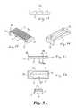
- FIGS. 5 a - 5 finclude perspective, side, end, top and bottom views of a superior endplate portion of the IBFD shown in FIGS. 1-2 , and including a cross-sectional and enlarged view of portions thereof.
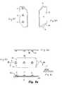
- FIGS. 6 a - 6 einclude perspective, side, end, top and bottom views of an inferior endplate portion of the IBFD shown in FIGS. 1-2 , including an enlarged view of a portion thereof.
- FIGS. 7 a - 7 einclude side, top and cross-sectional views of the inferior endplate portion of the IBFD shown in FIGS. 6 a - 6 e.
- FIGS. 8 a - 8 finclude side, top, bottom and perspective views of a track connector used in connection with the insertion apparatus shown in FIGS. 3-4 , including cross-sectional views of portions thereof.
- FIG. 8 gis a bottom perspective view of an alternative embodiment of a track connector used in connection with the insertion apparatus shown in FIGS. 3-4 .
- FIG. 9is a side perspective partial cut-away view of the IBFD and insertion apparatus shown in FIGS. 3-4 with the track connector shown in FIG. 8 b in accordance with one embodiment of the invention.
- FIG. 10is a side view of the IBFD and insertion apparatus shown in FIGS. 3-4 .
- FIGS. 11 a, bare top perspective and bottom views of a wafer for introduction into the IBFD of FIGS. 1-2 using the insertion apparatus as shown in FIGS. 3-4 and 9 .
- FIG. 12is a side cut-away view of the structure shown in FIG. 9 .
- FIG. 13is a top view of the distal end of the wafer-track portion of the insertion apparatus shown in the prior figures.
- FIGS. 14 a - care top, top perspective and top-perspective cut-away views of components of the insertion apparatus engaged with the inferior endplate portion of the IBFD illustrated in FIGS. 6-7 and including the distal end of the wafer track shown in FIG. 13 .
- FIG. 15 ais a top perspective view of a release plate, driver and the distal end of the wafer track of FIG. 13 .
- FIG. 15 bis a top view of components of the insertion apparatus engaged with the inferior endplate, including the release plate of FIG. 15 a .
- the track connectoris removed to show the position of the release plate and the distal end of the wafer track in the inserter cavity.
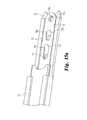
- FIG. 16 ais a bottom perspective view of the distal end of the wafer track of FIG. 13 with the track connector of FIGS. 8 a , 8 b mounted thereon.
- FIGS. 16 b - dare top, top perspective and top perspective cut-away views of components of the insertion apparatus engaged with the inferior endplate portion and including the track connector of FIG. 8 b prior to wafer insertion.
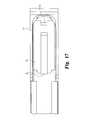
- FIG. 17is a top view of the insertion apparatus with a wafer situated within the inferior endplate portion of the IBFD. The superior endplate is removed to show the position of the wafer in the wafer cavity.
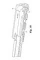
- FIG. 18is a perspective cut-away view of the insertion apparatus, the inferior endplate portion of the IBFD, including the track connector, and wafer shown in FIG. 17 .
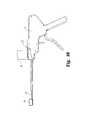
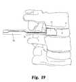
- FIG. 19is a side pictorial view of the insertion apparatus being used to insert an IBFD in accordance with the present invention into an intervertebral space.
- FIGS. 20 a - 20 cinclude side, top and end views of a disc space distractor for use with the insertion apparatus shown in the above identified figures.
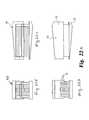
- FIGS. 21 a - 21 bare side and end cross-sectional views of an IBFD in accordance with one embodiment of the present invention with a stack of wafers introduced therein to one pre-determined height.
- FIGS. 21 c - 21 dare side and end cross-sectional views of the IBFD shown in FIGS. 21 a - 21 b stacked to a different height in which all of the wafers are contained within the endplates.
- FIGS. 22 a - dinclude side and end views of the IBFD shown in FIGS. 21 a - 21 b.
- FIGS. 23 a - 23 dinclude top and bottom perspective views, a side view and a cross-sectional view of a superior endplate for a sagittally curved embodiment of an IBFD of the present invention.
- FIGS. 24 a - 24 dinclude side, top perspective, top and end views of an inferior endplate for a sagittally curved embodiment of an IBFD of the present invention.
- FIGS. 25 a - care perspective, top and cross-sectional views of a transversely curved wafer for use with an IBFD of the present invention.
- FIG. 26is a side representation of an IBFD implanted in an intervertebral space with wafers as shown in FIGS. 25 a - c.
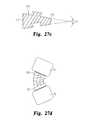
- FIGS. 27 a - care perspective, top and cross-sectional views of a transversely curved and angled wafer for use with an IBFD of the present invention.
- FIG. 27 dis a side representation of an IBFD implanted in an intervertebral space with wafers as shown in FIGS. 27 a - c.
- FIG. 28is a bottom perspective view of an interlocking wafer according to a further embodiment of the invention.
- FIG. 29is a top perspective view of the interlocking wafer shown in FIG. 28 .
- FIG. 30is an end elevational view of the interlocking wafer shown in FIGS. 28-29 .
- FIG. 31is a bottom elevational view of the interlocking wafer shown in FIGS. 28-30 with a second wafer engaged thereto, as depicted in phantom liens.
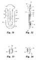
- FIG. 32is a side elevational view of the interlocking wafer shown in FIGS. 28-30 .
- FIG. 33is an enlarged partial side view of the region A of the wafer shown in FIG. 32 .
- FIG. 34is an enlarged partial side view of the region B of the wafer shown in FIG. 32 .
- FIG. 35is a bottom perspective view of an alternative configuration of an interlocking wafer according to the present invention.
- FIG. 36is a top perspective view of the alternative configuration shown in FIG. 35 .
- FIG. 37is a top elevational view of the alternative configuration shown in FIGS. 35-36 .
- FIG. 38is a bottom elevational view of the alternative configuration shown in FIGS. 35-36 .
- FIG. 39is an enlarged partial side cross-sectional view of the interlocking wafer depicted in FIG. 37 taken along line C-C as viewed in the direction of the arrows.
- FIG. 40is a top elevational view of yet another alternative configuration for an interlocking wafer according to the present invention.
- FIG. 41is a side elevational view of two wafers of the configuration shown in FIG. 40 depicted in their interlocking relationship.
- FIG. 42is a cross-sectional view of the two wafers illustrated in FIG. 41 .
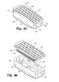
- FIG. 43is a top perspective view of an expandable device configured to receive a series of the wafers shown in prior figures.
- FIG. 44is an exploded view of the superior and inferior endplate components of the expandable device shown in FIG. 43 .
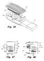
- FIG. 45is a top perspective view of the expandable device shown in FIG. 43 engaged to a wafer inserter apparatus.
- FIG. 46is side perspective view of the expandable device depicted in FIG. 44 , shown in an expanded configuration with a plurality of interlocking wafers disposed therein.
- FIG. 47is an end cross-sectional view of the expandable device and wafers shown in FIG. 46 taken along line E-E.
- FIG. 48is an end perspective cross-sectional view of the expandable device and wafers shown in FIG. 46 taken along line E-E.
- an expandable distraction device in the form of an interbody fusion device (IBFD) 10includes a superior endplate 12 and an inferior endplate 14 that define a wafer cavity 19 , as shown in FIGS. 1-2 .
- the superior and inferior surfaces of the endplatesdefine engagement ribs 16 U and 16 L that are configured to engage or grip the vertebral endplates of opposed vertebrae in a spine.
- the ribs 16 U and 16 Lare configured to prevent expulsion of the IBFD under normal spinal loads.
- the ribsmay have a saw tooth shape that is inclined toward the opening through which the IBFD is inserted into the interbody space. Angling the ribs toward the opening also angles them away from the direction of insertion so that the IBFD can be easily inserted into a collapsed space.
- the IBFD 10also defines an inserter cavity 18 that engages a portion of an inserter apparatus 50 , as shown in FIGS. 3-4 .
- the inserter apparatus 50defines a wafer track 52 along which a plurality of wafers, or expansion members, are conveyed to fill the wafer cavity 19 .
- the IBFD 10has a height across the superior and inferior endplates 12 , 14 that is less than the normal anatomic height of a typical intervertebral disc space.
- the inventioncontemplates that a series of expansion members, such as wafers, are introduced into the wafer cavity 19 to at least fill all or part of the cavity, and to distract the opposing vertebrae by separating the superior and inferior endplates. Insertion of the wafers separates the endplates to expand the height of the IBFD within the intervertebral or interbody space and to ultimately restore the normal anatomic height of the instrumented disc space.
- the superior endplate 12includes an upper wall 22 on which the engagement ribs 16 U are defined.
- the interior face of the upper wallis thickened in a reinforcement region 23 .
- This regionhelps maintain the integrity of the superior endplate 12 and provides a strong surface against which a lifting force can be applied by successive insertion of the wafer.
- Region 23is also configured to contain and to cooperate with the wafers, as described below, to provide lateral and torsional stability to the wafer stack.
- the upper wallterminates in an anatomically anterior end wall 24 and an anatomically posterior end wall 25 that integrate with the inferior endplate 14 as described below.
- the reinforcement region 23defines outwardly and laterally projecting ribs 27 that engage cooperating notches 36 defined in the interior of the inferior endplate 14 . Details of the inferior endplate are shown in FIGS. 6-7 .
- the endplate 14includes a bottom wall 30 on which the engagement ribs 16 L are defined.
- the bottom wall 30terminates in an end wall 32 and a ledge 33 .
- the anterior end wall 24 of the superior endplate 12overlaps the end wall 32 and end ledge 33 when the endplates are initially assembled.
- the two end walls 24 and 30overlap over the majority of the height of the end wall 32 so that as the superior and inferior endplates are pushed apart the two endplates remain in contact and continue to define the wafer cavity 19 , providing stability to the IBFD as it expands.
- the inferior endplate 14also defines side walls 35 that define the wafer cavity and ultimately help retain the wafers within the cavity as they are sequentially inserted.
- the inner face of the side wallsdefines notches 36 that are aligned for engagement by the ribs 27 in the superior endplate 12 .
- the interior of the inferior endplate 14includes opposite surfaces 38 that structurally reinforce the IBFD under large compressive loads. Slightly offset from the walls 38 are support rails 40 ( FIG. 6 b ) that support the track connector 46 shown in FIGS. 8 a - 8 f .
- the top surface 49 of the track connector 46is configured to be superior to surface 38 such that any compressive load from the wafer stack is transmitted through the bottom surface of the track connector to the support rails 40 .
- the end walls 38 of the endplate 14also form end notches 43 ( FIG. 7 c ) that are complementary to the end edges of the track connector 46 in one embodiment of the invention.
- the end walls 38 and rails 40 of the endplate 14define a connector channel 42 , as shown in FIG. 7 a , which is configured to receive the distal end of the wafer track of inserter apparatus 50 , as described below.
- the superior and inferior endplates 12 , 14may be formed of a biocompatible material with sufficient strength to support the adjacent vertebrae without fatigue and fracture.
- the two endplatesare molded from a biocompatible polymeric material, such as, for example, PEEK or a biocompatible composite material, such as, for example carbon-fiber-reinforced PEEK.
- the materialmay also be selected to permit tissue ingrowth to integrate with the vertebral endplates.
- the endplatescan further be formed from a moldable or formable biologic material, such as bone.
- the IBFD 10is configured to be introduced into the interbody space by an introducer or inserter apparatus 50 .
- the insertercan be constructed and operated like the insertion apparatus disclosed in U.S. Pat. No. 6,595,998, entitled “Tissue Distraction Device”, which issued on Jul. 22, 2003, to the assignee of the present invention.
- the disclosure of this patent, and particularly its discussion of the wafer inserter,is incorporated herein by reference.
- the insertercan be constructed and operated like the insertion apparatus disclosed in co-pending application Ser. No. 10/813,819, entitled “Tissue Distraction Device”, filed on May 31, 2004, and assigned to the assignee of the present invention.
- the disclosure of this co-pending applicationis incorporated herein by reference.
- the apparatusincludes a wafer track 52 along which wafers are conveyed to fill the wafer cavity 19 within the IBFD and ultimately to expand the height of the IBFD. Once the last wafer has been introduced into the IBFD it is necessary to remove the inserter 50 .
- the preferred embodiment of the inventioncontemplates a track connector 46 that helps to integrate the wafer track 52 with the interior cavity of the IBFD and to provide a support surface for the wafer stack within the IBFD.
- the connector 46includes connector posts 47 that project downward with the IBFD, as best seen in FIG. 9 . These posts engage corresponding openings 71 in an insertion plate 70 (see FIG. 12 ) to provide an interface between the inserter apparatus 50 and the IBFD.
- the track connector 46defines interface edges 48 at its opposite ends that are configured to conform to wall 38 in the inferior endplate 14 (see FIG. 6 b ).
- the track connectormay also include end edges 46 a flanking the interface edges that contact wall edges 38 a of the endplate 14 to limit the movement of the track connector into the endplate.
- the track supportincludes a ramp 49 a that helps direct incoming wafers upward from the wafer track 52 to the wafer support surface 49 within the IBFD.
- a track connector 46 ′includes a modified proximal end 48 ′ and distal end 48 ′′, but still retains the connector posts 47 , wafer support surface 49 and ramp 49 a .
- the modified distal end 48 ′′catches against a lip 39 formed in the inferior endplate, as shown in FIGS. 9 , 12 to prevent removal of the track connector 46 ′ once it is positioned with the assembled IBFD.
- the distal end of the track connector 46 ′further defines end edges 46 a ′ that contact the wall edges 38 a , as depicted in FIG. 16 b, in the same manner as the end edges 46 a described above.
- the wafer inserter apparatus 50provides an avenue for passage of wafers 55 from a wafer cartridge 54 into the IBFD.
- the inserter apparatusincludes a cartridge gun that extracts wafers 55 consecutively from a stack within the cartridge 54 and conveys them along the track 52 to the IBFD.
- the wafers 55are configured for transport along the track 52 and for interlocking engagement within the IBFD.
- the wafersinclude a leading bevel 56 and an opposite trailing bevel 57 to facilitate movement of each successive wafer underneath the immediately prior inserted wafer.
- the bevels 56 , 57help the incoming wafer dislodge and slide underneath the wafer stack already resident within the IBFD.
- a wafer driver 65may be provided within the wafer track 52 to advance each wafer into the wafer cavity. The driver 65 can also help hold the lowermost wafer of the stack in position as the inserter apparatus 50 is removed.
- the wafers 55also include interdigitating upper and lower surfaces 58 , 59 , respectively.
- the surfacescan assume a variety of configurations intended to prevent relative longitudinal movement between wafers in the stack as well as for lateral and rotational stability.
- the wafers 55 and their respective surfacescan be constructed as disclosed in U.S. Pat. No. 6,595,998 cited above. The disclosure of this patent, and most particularly its discussion of the construction of the wafers, is incorporated herein by reference.
- the upper surface 58defines a ridge 60 and spaced rib 61 extending along the longitudinal axis of the wafer.
- the lower surfacedefines a linear trough 62 that receives the ridge 60 , and a notch 63 that receives the rib 61 .
- the insertion configuration for the IBFD and wafer inserter apparatusis generally depicted in FIG. 12 .
- the wafer track 52 of the inserter apparatusengages the IBFD with the track end 53 contacting the proximal faces of both the inferior endplate 14 and the superior endplate 12 .
- a wafer 55is shown resting on the wafer support surface 49 of the track connector 46 ′.
- the track connector 46rests on the support rail 40 (see FIG. 6 ) with its posts 47 projecting downward toward the post openings 44 in the inferior endplate 14 .
- the postsdo not necessary extend into the openings 44 . Instead, the post openings 44 facilitate the assembly of insertion apparatus to the track connector prior to use.
- Beneath the track connector 46reside an insertion plate 70 and a release plate 75 immediately adjacent the connector 46 . Both plates provide openings to receive the connector posts 47 therethrough, including openings 71 in the insertion plate and openings 76 a - c in the release plate.
- the insertion plate 70may define a release track 72 (as shown in FIG. 14 c ) within which the release plate 75 slides.
- the release trackmay be provided to increase the stiffness of the insertion plate, or may be eliminated to permit a reduction in width of the components.
- the assembly of the components of the inserter apparatus 50 within the IBFD 10is depicted sequentially in FIGS. 13-18 .
- the insertion plate 70is shown in FIG. 13 .
- the plate 70is integral with the wafer track 52 .
- the insertion plate 70essentially supports the IBFD with the plate 70 extending into the wafer cavity and the track end 53 abutting the IBFD.
- This plate 70will be removed with the inserter apparatus 50 , leaving the IBFD within the interbody space.
- the post openings 71are sized to receive the connector posts 47 therethrough.
- the insertion plate 70sits below the support rail 40 in the inferior endplate 14 with its post openings 71 aligned with the post openings 44 in the endplate 14 .
- the release plate 75is slidably disposed within the release track 72 in the insertion plate 70 .
- the release plate 75is slidably disposed on top of the insertion plate 70 without any release track 72 .
- the release plate 75includes openings 76 a - c corresponding to each of the connector posts 47 .
- the distal edge 77 a - c of each openingis sharpened so that they will sever the posts 47 from the connector plate 46 when the release plate is pulled proximally, or out of the IBFD.
- the opening 76 ais generally sized slightly larger than the post 47 , while the other two openings 76 b - c are increasingly elongated.
- This configurationallows the distal-most post to be cleanly severed before the middle post is severed, and the middle post to be severed before the proximal post. This approach reduces the force needed to sever the posts. Once the posts are severed, they are retained within the post openings 71 via an interference fit, since they are no longer needed to hold the track connector within the IBFD. When the posts are severed, the inserter apparatus 50 can be removed from the implanted IBFD without risk of retracting the IBFD.
- FIGS. 16 a - dshow the placement of the track connector on top of the insertion plate 70 and release plate 75 .
- the wafer support surface 49is generally contiguous with wall 38 of the inferior endplate 14 .
- the wafer support surface 49is superior to wall 38 of the inferior endplate 14 . This alternate embodiment ensures that the compressive load from the wafer stack is transmitted through the wafer support surface 49 and not through wall 38 .
- a first wafer 55is added in FIGS. 17-18 .
- the inserter apparatus 50 and the IBFD 10are shown in position for implanting the IBFD within an interbody space. It is contemplated that the interbody or intradiscal space will be prepared in a known manner. In particular, the disc nucleus is removed by known means, preferably leaving the disc annulus A relatively intact. A portal is formed in the annulus that is sized to the dimensions of the IBFD 10 in its un-expanded configuration (as shown in FIGS. 1-2 ).
- the IBFDis sized to be received in the unexpanded state through the portal into the disc space without any pre-distraction.
- pre-distractionmay be used to slightly elevate the disc space so as to allow receipt of the unexpanded IBFD through the portal.
- Such pre-distractionwhich can occur using conventional techniques, is not intended to achieve the final disc space height.
- One approachis to use the distractor 80 shown in FIGS. 20 a - 20 c . This distractor includes a distal end 82 having a height H greater than its width W. The height H of the distal end 82 is substantially constant over the insertion length L.
- the distractoris inserted into the disc space at a location adjacent to but laterally spaced from the location where the IBFD is to be inserted with its larger dimension parallel to the vertebral endplates. As such, no distraction occurs during insertion of the distractor 80 .
- the handle 84is used to rotate the distractor 80 until the larger dimension contacts and pushes apart the vertebral endplates.
- the distractor 80can be held in position as the IBFD is maneuvered into the interbody space using the inserter apparatus 50 . After removal of the distractor, a second IBFD may be inserted adjacent to the first implanted IBFD.
- the IBFDcan be expanded to a specific height, with its height being determined by the number of wafers 55 inserted into the IBFD.
- the superior and inferior endplates 12 , 14 and the wafershave a pre-determined height or thickness.
- the endplatesinclude overlapping portions to help stabilize the stack, in particular the end walls 24 and 32 .
- the stack heightwill change when the inserter apparatus is dislodged from the IBFD and removed.
- the wafer stackwill shift slightly downward when the insertion plate and release plates are removed, allowing the track connector 46 to drop down.
- the IBFD 90 shown in FIGS. 21 a - d and FIGS. 22 a - dincludes superior and inferior endplates 92 , 94 that are angled. These endplates are configured to restore or maintain a particular angle of the vertebral motion segment. For instance, if the IBFD 90 is used in the lumbar spine, the endplates are defined at a lordotic angle.
- the endplates 80 , 82 in FIGS. 23 a - d and FIGS. 24 a - dare also configured to have arcuate upper and lower surfaces for introduction into and anatomical support of the lumbar spine.
- FIGS. 25 a - 27 dAlternative concepts for the endplates and the wafers are shown in FIGS. 25 a - 27 d .
- a curved wafer 100is provided in FIGS. 25 a - c .
- the waferincludes interlocking dovetail features 101 and 104 and locking notches 102 to help hold the wafer stack together.
- the endplates 105 , 106can be angled to restore the lordotic angle of the motion segment with the wafer stack therebetween.
- the waferscan provide the lordotic angle, such as the wafer 110 shown in FIGS. 27 a - c .
- the wafer 110includes one end 111 that is thicker than the opposite end 112 .
- the waferscan be contained within endplates 115 , 116 that are planar- i.e., that do not incorporate the lordotic angle.
- the wafers 55 shown in FIGS. 11 a - binclude interlocking upper and lower surfaces 58 , 59 .
- the interlocking featuresinclude a ridge 60 and rib 61 that are fed longitudinally into a corresponding complementary shaped trough 62 and notch 63 .
- the stacked wafersresist dislodgement in the fore-aft (longitudinal) degree of freedom and resist relative rotation between adjacent wafers about a vertical axis extending through the stack.
- the wafers 110 shown in FIGS. 27 a - cutilize a dovetail interface to interlock adjacent wafers against vertical separation. Neither of these prior embodiments provides a positive interlocking arrangement between adjacent wafers or complete interlocking in multiple degrees of freedom.
- An expansion member 160 depicted in FIGS. 28-34provides a positive interlock between adjacent expansion members that prevents dislodgement or separation in multiple degrees of freedom.
- the expansion memberis in the form of an interlocking wafer 160 that is generally planar between the insertion end 162 and the trailing end 164 .
- the insertion end 162defines an upwardly facing beveled tip 163
- the trailing enddefines a downwardly facing beveled tip 165 .
- the beveled tips 163 , 165are configured to contact each other to push one wafer up as the other wafer is introduced into the expandable device, such as the IBFD 10 described above.
- the wafer 160provides interlocking features between the lower surface 170 and the upper surface 190 . These interlocking features are configured so that the wafers become positively interlocked as one wafer is introduced beneath the next successive wafer as the wafer stack is formed. Ultimately, every wafer in the stack is positively interlocked with the adjacent wafers above and below. Moreover, the interlocking features are configured so that the interlocking elements mesh smoothly without raising and lowering the adjacent wafer during insertion of a new wafer.
- the lower surface 170 of the wafer 160defines a recess 172 generally centered along the length or longitudinal axis of the wafer.
- the recess 172is open at the trailing end 164 but is preferably closed at the insertion end 162 , as shown in FIG. 28 .
- the recess 172is bounded by opposite side walls 174 and an end wall 176 . Part of the interlocking aspect of the wafer 160 is achieved by an entry undercut 175 defined in the side walls 174 at the open entry end of the recess ( FIG. 33 ).
- the end wall 176defines a similar undercut 177 ( FIG. 34 ).
- the upper surface 190 of the waferprovides features that interlock with the undercuts 175 , 177 .
- the upper surface 190includes a leading boss 192 at the insertion end 162 of the wafer, as shown in FIG. 29 .
- the leading boss 192defines an engaging undercut 193 ( FIG. 34 ) that is sized to fit snugly within the undercut 177 in the end wall 176 of the lower surface 170 .
- the upper surface 190further includes a trailing boss 195 that extends from the trailing end 164 toward the leading boss 192 , but terminating short of the leading boss.
- the trailing boss 195includes opposite side walls 196 that are configured for sliding contact with the side walls 174 of the recess 172 in the lower surface of an adjacent wafer to help prevent relative rotational movement of stacked wafers. These opposite side walls form trailing undercuts 202 ( FIG. 34 ) that engage the undercuts 175 in the side walls of the lower surface recess.
- the beveled tip 163 at the insertion end 162contacts the beveled tip 165 of the trailing end 164 of the previously inserted wafer, thereby lifting that wafer to receive the newly inserted wafer.
- the leading boss 192travels across the entry surface 187 and enters the recess 172 , followed by the trailing boss 195 .
- the mating surface 204aligns with the entry surface 187 , and the undercut 193 and undercut 202 substantially simultaneously slide within the corresponding undercuts 177 and 175 in the lower surface 170 of the previous wafer.
- each side wall 174 of the lower surface recess 172forms a latch element 180 followed by an indentation 182 (i.e., between the latch element and the end wall 176 of the recess).
- Each side wall 196 of the trailing boss 195 of the upper surface 190forms complementary latch elements 197 followed by indentations 199 (i.e., between the upper surface latch elements and the trailing end 164 of the wafer).
- the latch elements 197are particularly configured for engagement within the side wall indentations 182 in the lower surface recess 172 .
- the upper surface indentations 199are configured to receive the lower surface latch elements 180 .
- This engagementis depicted in FIG. 31 , in which wafers 160 and 160 ′ (in phantom) are interlocked with the latch elements 180 engaging the indentations 199 ′ and the latch elements 197 ′ engaging the indentations 182 .
- the latch elements 180 and 197 ′cooperate to prevent relative fore and aft movement between the wafers 160 , 160 ′, as well as relative rotational movement.
- the leading boss 192 on the upper surface 190is sized to pass between the latch elements 180 on the lower surface of the adjacent wafer.
- the latch elements 197 of the upper surfacemust have a normal engagement orientation that is wider than the recess 172 between the latch elements 180 of the lower surface 170 . Consequently, the present invention contemplates a resilient feature of the wafer 160 that allows resilient deformation of one wafer relative to the other as the latch elements pass by each other.
- the waferdefines a central slot 185 that passes between the lower and upper surfaces.
- the slot 185preferably extends along a substantial portion of the length of the wafer, and most preferably has a length sufficient so that the latch elements 197 are positioned generally at the mid-point of the length of the slot. With this configuration, the slot 185 has its region of maximum deformation where it is needed—at the latch elements. Thus, when one wafer is inserted below a prior wafer, the slot 185 of the newly inserted wafer may constrict as the latch element 197 ′ contacts the latch element 180 . Once the latch element 197 ′ reaches the indentation 182 , the resilient nature of the wafer allows the slot 185 to spring back to its original width, thereby locking the latch element 197 ′ within the indentation 182 .
- the wafer 160includes a pair of pre-load recesses 208 on each side surface 206 .
- the recessesengage complementary projections in the expandable device 250 ( FIG. 44 ) to hold the wafer in a predetermined position until dislodged from below. Details of this pre-load feature follow below in the discussion of the expandable device 250 .
- FIGS. 35-38A further embodiment of an interlocking wafer 215 is depicted in FIGS. 35-38 .
- This wafer 215includes a lower surface 216 , an upper surface 217 and a thru slot 219 that are similar to the corresponding elements of the wafer 160 .
- the lower surface 216defines a recess 222 formed by side walls 223 .
- the overall shape of the recess 222is similar to the shape of the recess 172 , except that the single pair of latch elements in the prior embodiment is replaced by three pairs of latch elements 224 , 225 and 226 .
- the upper surface 217includes a leading boss 228 and a trailing boss 229 that are also similar to the like elements of the prior embodiment.
- the trailing boss 229incorporates latch elements 231 , 232 and 233 that are configured to mate or interlock with the latch elements 224 - 226 .
- the latch elements 224 - 226 and 231 - 233narrow toward the insertion end 220 of the wafer 215 so that the lateral space between the forward latch elements 226 is narrower than between the middle latch elements 225 , which is narrower than the gap between the trailing latch elements 224 .
- This configurationproduces a ratcheting effect as a subsequent wafer interlocks with a previous wafer.
- the multiple latch elementsensure that adjacent wafers are firmly interlocked to prevent separation when the wafer stack is subjected to in situ forces.
- the wafer 215also includes undercuts to interlock the wafers in the vertical degree of freedom.
- the recess 222defines opposite undercuts 235 a inboard from the closed end of the recess, as shown in FIGS. 38-39 .
- the leading boss 228 of the upper surface 217defines complementary undercuts 236 a , as shown in FIGS. 37 , 39 , to mate with the undercut 235 a when one wafer is fully inserted into the recess of a prior wafer.
- the trailing end of the recess 222defines opposite undercuts 235 b while the trailing boss 229 defines complementary mating undercuts 236 b , which are all similar to the like components on the wafer 160 .
- FIGS. 40-42Yet another embodiment of an interlocking wafer 239 is illustrated in FIGS. 40-42 .
- the lower surface 247 and upper surface 248are configured for interlocking engagement, including insertion end mating undercuts 246 ( FIG. 42 ) and trailing mating undercuts 249 ( FIG. 41 ).
- the wafer 239includes a leading boss 240 that defines an undercut 241 .
- a wide slot 243is defined within the wafer from a point below the undercut 241 to a location at the middle of the wafer.
- a trailing boss 242is formed in alignment with the slot and includes a flexible portion or arm 244 that is angled into the slot 243 .
- the flexible portion 244defines an undercut 245 at its tip that is arranged to contact the upper surface 238 at the leading boss 240 , as best shown in FIG. 42 .
- the leading boss 240 ′pushes the flexible arm 244 up into contact with the undercut 241 in the leading boss 240 of the upper wafer 239 .
- the flexible arm 244is then wedged between the leading boss 240 of the upper wafer 239 and the leading boss 240 ′ of the lower wafer 239 ′ to interlock the wafers in multiple degrees of freedom.
- the wafer 160 of FIGS. 28-34 , the wafer 215 of FIGS. 35-39 , and the wafer 239 of FIGS. 40-42each provide features for interlocking relationship between adjacent wafers. Moreover, these features interlock the wafers in several degrees of freedom, or against relative displacement in several directions.
- the interlocking latch elements and indentationslock adjacent wafers in shear—i.e., relative movement fore and aft, and side-to-side.
- the undercuts, 175 , 177 , 193 and 202for instance, resist fore-and-aft movement.
- the relationship between the latch elements and the undercut interfaceslocks the wafers in tension.
- One important objective of interlocking in multiple degrees of freedomis to prevent dislodgement of adjacent wafers as a stack is being formed.
- the height of the stackincreases so that intermediate wafers of the stack are no longer supported by the walls of the IBFD (such as IBFD 10 ).
- the unsupported wafersmay be susceptible to sliding apart or rotating relative to each other, which may disturb the integrity of the completed IBFD.
- Interlocking each wafer in the stackforms a substantially rigid stack that extends perpendicularly from the base of the stack upward into contact with the opposing surface.
- interlocking the lowermost wafer to the next adjacent waferhelps hold that lowermost wafer against the insertion force of a newly inserted wafer.
- Interlocking the lowermost wafer to the remainder of the stackalso helps maintain the lowermost wafer in proper position to receive the next wafer to be added to the stack. It is important that the lowermost wafer not be canted forward or backward. If canted forward, the trailing end 164 of the wafer 160 , for instance, will block passage of the next wafer to be introduced. If canted backward, the next wafer will not engage any of the interlocking features so that the prior wafer stack will simply rest unconstrained on the upper surface 190 of the wafer.
- each wafermay include pre-load recesses 208 on the side surfaces 206 of the wafers 160 . These pre-load recesses are engaged by mating ribs in the inferior component of an expandable distraction device, such as the device 250 shown in FIGS. 43-46 .
- the device 250includes a superior plate 251 and an inferior plate 252 that are similar in function to the like components of the device 10 described above.
- the plates 251 , 252may include engagement ribs 254 that are configured to engage the opposing body tissue surfaces to be distracted. For instance, where the device 250 is used for interbody distraction, with or without fusion, the ribs 254 may be configured to engage the vertebral endplates.
- Other engagement or tissue gripping configurationsmay also be used, such as, for example, teeth, fins, ridges, threads and various combinations thereof. Additionally, porous surface coatings, indentations or openings may be used to promote bone ingrowth.
- the superior and inferior plates 251 , 252are similar to the plates of the device 10 in that the plates are initially engaged during insertion into the body space.
- the side walls 253 of the inferior plate 252define interior projecting ribs 265
- the superior plate 251defines a series of mating grooves 268 on opposite sides of a lower hub 269 of the plate ( FIGS. 44 , 48 ).
- These ribs and groovesform a releasable engagement feature that initially holds the two plates together, and that is configured to disengage upon pressure from the insertion of the expansion members or wafers.
- two rows of grooves 268are provided, each row configured for a releasable snap-fit with the ribs 265 .
- the superior plate 251is snapped to the inferior plate 252 , with the hub 269 disposed within between the side walls 253 of the inferior plate.
- the hub 269may be formed on the sides of the lower hub 269 such that upon insertion of an initial expansion member or wafer the ribs 265 release from the grooves 268 disengaging the superior and inferior endplates 251 , 252 .
- the side walls 253 of the inferior plate 252together with front end wall 255 and rear end wall 259 form an open, upwardly facing full bounded cavity 261 .
- the inferior plate 252is open at one end to receive a wafer inserter or track, such as the track 52 (see FIG. 45 ).
- the interior platedefines an insertion channel 256 that includes a wafer channel 257 extending through rear end wall 259 and through which successive wafers may be inserted, and an inserter channel 258 .
- the wafer channel 257is defined in part by wafer support ledges 260 formed on the inside of each side wall 253 , as shown in FIG. 44 .
- the ledges 260provide a sliding surface for each new wafer being introduced through the track 52 into the device 250 , as shown in FIGS. 47-48 .
- each wafer 160The function of the pre-load recesses 208 in each wafer 160 is also depicted in FIGS. 47-48 .
- the lowermost waferrests on the ledges 260 .
- the next adjacent waferis restrained by the ribs 265 engaged within the corresponding pre-load recesses 208 on each side of the device.
- the ribs and recessesinterlock, the displaced wafer assumes a stable and flat orientation so that the interlocking components of the newly introduced wafer will align with the mating interlocking components of the displaced wafer.
- ribs 265 and recesses 208Another benefit of the ribs 265 and recesses 208 is that this snap-fit type engagement requires a small load to dislodge or disengage.
- This pre-loadmay be easily overcome by the introduction of a new wafer underneath the existing stack of wafers. However, the pre-load is sufficiently high that the stack cannot be inadvertently disengaged or moved upward by anatomic forces of extraneous forces occurring during the initial implantation process.
- the hub 269 of the superior plate 251includes wafer mating features 274 that are preferably identical to the features on the lower surface 170 of each wafer 160 , for example.
- the hub 269is disposed within cavity 261 and sits on or closely adjacent to the wafer support ledges 260 , with the ribs 265 engaged in the uppermost mating groove 268 .
- the interlocking features on the upper surface 190 of the wafer 160engage the mating features 274 on the underside of the boss 269 while the wafer lifts the boss, and therefore the superior plate 251 , upwardly.
- the superior plate 252has been lifted enough so that the lowermost groove 268 , if provided, snaps into engagement with the ribs 265 . If there is only one groove 268 , the superior plate 251 disengages from the inferior plate 252 upon entry of the first wafer 160 . As each successive wafer 160 is introduced, this process repeats itself, with each new wafer becoming fully interlocked with the next preceding wafer. It should be noted that the two lowermost wafers 160 , but at least the bottom wafer (as seen in FIGS. 47-48 ), reside within the cavity 261 of the inferior plate 252 , fully contained and constricted by the opposing side walls 253 and the front and rear end walls 255 , 259 .
- This embodiment of the inventioncontemplates a mechanism for releasably connecting the expandable device 250 to the wafer track assembly 52 .
- This mechanismincorporates a movable element that is operable to disengage the device from the track assembly.
- the inferior plate 252includes at least one, and most preferably three, upwardly projecting posts 262 ( FIG. 44 ).
- the track assemblyincludes an insertion plate 270 that is similar to the plate 70 ( FIG. 12 ) of the previous embodiment.
- the plate 270defines a plurality of openings 271 , each configured to receive a corresponding post 262 therethrough.
- the openings 271 in the insertion plate 270may be provided with a cutting edge that is configured to sever the posts 262 when the plate 270 is retracted within the track assembly 52 .
- the connection between the inferior plate 252 and the insertion plate 270is broken, which ultimately releases the inferior plate and device 250 from the track assembly 52 .
- the track assemblymay be removed while the device 250 is left in situ.
- the track assembly 52may be used to help maintain the inferior plate 250 in position between the body tissues to be distracted. Once disengaged, the inferior plate remains within the space, so that the inferior plate essentially acts as a base wafer upon which the wafer stack is built. It is therefore important for the inferior plate 252 , acting as a base wafer, to remain stable and steadfast in contact with the inferior tissue surface.
- the inferior plate 252When the device 250 is used as an interbody device, the inferior plate 252 must remain in solid, fixed contact with the inferior vertebral endplate, assisted by the engagement ribs 254 , or other gripping surfaces or bone ingrowth features, as described above. In one preferred procedure, the opposing endplates are scraped or otherwise reduced to bleeding bone to enhance the temporary and permanent fixation of the device plates 251 and 252 to the adjacent vertebral bodies.
- the tissue space to be distractedwill be expanded by expansion of the device 250 .
- the force needed to push the wafer underneath the immediately prior wafermay be increased by the force needed to distract the body space.
- additional distractionmay be required.
- a separate distraction instrumentmay be introduced into the body space and used to temporarily distract the space enough to allow insertion of the device 250 .
- the distractor 80 shown in FIG. 20may be used to open the space sufficiently for insertion of the device. As the tip is rotated, it forces the opposing tissue surfaces apart.
- the distraction tool 80would be introduced toward one side of the space to leave adequate room within the heart of the space to receive the expandable device 250 .
- an additional distraction toolmay be used at an opposite side of the space.
- the distraction tool 80may then be removed from the space.
- a wider distraction tool tipmay be used to temporarily expand the space to the intended distracted height.
- the expandable device 250would be expanded until the device spanned the pre-distracted space, at which time the distraction tool(s) may be removed.
- the device 250has a non-expanded height of about 6 mm at its leading (or insertion) end.
- the tissue engaging surfaces of the superior and inferior plates 251 , 252are preferably domed in specific embodiments intended for use in distracting an intervertebral space.
- the non-expanded domed devicethen has a maximum height in the center of about 8.5 mm with the engagement ribs.
- the maximum height of a non-expanded flat device with engagement ribswould be about 7.0 mm over its length.
- the overall length and width of the devicemay be calibrated to substantially fill the intervertebral space, or may be preferably sized to leave room around the device for the introduction of filler material around the device.
- the device 250has a length of about 24 mm and a width of about 9 mm, which leaves sufficient space around the device and within an intact intervertebral disc to pack an osteo-inductive and/or osteo-conductive material.
- the materialmay be, for instance, bone chips that are fed into the space around the device 250 using a minimally invasive cannula.
- the interlocking wafers 160 , 215 or 239are configured to add about 1.0 mm to the expanded height of the device 250 .
- the height his about 1.0 mm.
- the width and length of the wafersis dictated by the interior dimensions of the inferior plate 252 where the wafers are initially introduced into the wafer stack.
- the wafershave a width of about 7.7 mm and a length of about 20 mm to fit within a correspondingly sized space in the inferior plate 252 .
Landscapes
- Health & Medical Sciences (AREA)
- Engineering & Computer Science (AREA)
- Biomedical Technology (AREA)
- Orthopedic Medicine & Surgery (AREA)
- Neurology (AREA)
- Transplantation (AREA)
- Heart & Thoracic Surgery (AREA)
- Oral & Maxillofacial Surgery (AREA)
- Cardiology (AREA)
- Vascular Medicine (AREA)
- Life Sciences & Earth Sciences (AREA)
- Animal Behavior & Ethology (AREA)
- General Health & Medical Sciences (AREA)
- Public Health (AREA)
- Veterinary Medicine (AREA)
- Physical Education & Sports Medicine (AREA)
- Prostheses (AREA)
- Container, Conveyance, Adherence, Positioning, Of Wafer (AREA)
- Lining Or Joining Of Plastics Or The Like (AREA)
Abstract
Description
Claims (12)
Priority Applications (8)
| Application Number | Priority Date | Filing Date | Title |
|---|---|---|---|
| US11/211,346US7931688B2 (en) | 2004-08-25 | 2005-08-25 | Expandable interbody fusion device |
| US13/092,334US8641767B2 (en) | 2004-08-25 | 2011-04-22 | Expandable interbody fusion device |
| US13/348,704US8337562B2 (en) | 2004-08-25 | 2012-01-12 | Device for distracting body tissue |
| US14/161,781US9095446B2 (en) | 2004-08-25 | 2014-01-23 | Expandable interbody fusion device |
| US14/339,978US9192484B2 (en) | 2004-08-25 | 2014-07-24 | Expandable interbody fusion device |
| US14/939,007US9675469B2 (en) | 2004-08-25 | 2015-11-12 | Expandable interbody fusion device |
| US15/618,378US10195052B2 (en) | 2004-08-25 | 2017-06-09 | Expandable interbody fusion device |
| US16/265,540US10828172B2 (en) | 2004-08-25 | 2019-02-01 | Expandable interbody fusion device |
Applications Claiming Priority (2)
| Application Number | Priority Date | Filing Date | Title |
|---|---|---|---|
| US60442204P | 2004-08-25 | 2004-08-25 | |
| US11/211,346US7931688B2 (en) | 2004-08-25 | 2005-08-25 | Expandable interbody fusion device |
Related Child Applications (1)
| Application Number | Title | Priority Date | Filing Date |
|---|---|---|---|
| US13/092,334DivisionUS8641767B2 (en) | 2004-08-25 | 2011-04-22 | Expandable interbody fusion device |
Publications (2)
| Publication Number | Publication Date |
|---|---|
| US20060058807A1 US20060058807A1 (en) | 2006-03-16 |
| US7931688B2true US7931688B2 (en) | 2011-04-26 |
Family
ID=36000606
Family Applications (9)
| Application Number | Title | Priority Date | Filing Date |
|---|---|---|---|
| US11/211,346Active2029-04-29US7931688B2 (en) | 2004-08-25 | 2005-08-25 | Expandable interbody fusion device |
| US11/211,347Active2029-11-25US7875078B2 (en) | 2004-08-25 | 2005-08-25 | Expandable interbody fusion device |
| US13/092,334Active2026-09-12US8641767B2 (en) | 2004-08-25 | 2011-04-22 | Expandable interbody fusion device |
| US13/348,704Expired - Fee RelatedUS8337562B2 (en) | 2004-08-25 | 2012-01-12 | Device for distracting body tissue |
| US14/161,781Expired - LifetimeUS9095446B2 (en) | 2004-08-25 | 2014-01-23 | Expandable interbody fusion device |
| US14/339,978Expired - LifetimeUS9192484B2 (en) | 2004-08-25 | 2014-07-24 | Expandable interbody fusion device |
| US14/939,007Expired - Fee RelatedUS9675469B2 (en) | 2004-08-25 | 2015-11-12 | Expandable interbody fusion device |
| US15/618,378Expired - LifetimeUS10195052B2 (en) | 2004-08-25 | 2017-06-09 | Expandable interbody fusion device |
| US16/265,540Expired - Fee RelatedUS10828172B2 (en) | 2004-08-25 | 2019-02-01 | Expandable interbody fusion device |
Family Applications After (8)
| Application Number | Title | Priority Date | Filing Date |
|---|---|---|---|
| US11/211,347Active2029-11-25US7875078B2 (en) | 2004-08-25 | 2005-08-25 | Expandable interbody fusion device |
| US13/092,334Active2026-09-12US8641767B2 (en) | 2004-08-25 | 2011-04-22 | Expandable interbody fusion device |
| US13/348,704Expired - Fee RelatedUS8337562B2 (en) | 2004-08-25 | 2012-01-12 | Device for distracting body tissue |
| US14/161,781Expired - LifetimeUS9095446B2 (en) | 2004-08-25 | 2014-01-23 | Expandable interbody fusion device |
| US14/339,978Expired - LifetimeUS9192484B2 (en) | 2004-08-25 | 2014-07-24 | Expandable interbody fusion device |
| US14/939,007Expired - Fee RelatedUS9675469B2 (en) | 2004-08-25 | 2015-11-12 | Expandable interbody fusion device |
| US15/618,378Expired - LifetimeUS10195052B2 (en) | 2004-08-25 | 2017-06-09 | Expandable interbody fusion device |
| US16/265,540Expired - Fee RelatedUS10828172B2 (en) | 2004-08-25 | 2019-02-01 | Expandable interbody fusion device |
Country Status (2)
| Country | Link |
|---|---|
| US (9) | US7931688B2 (en) |
| WO (1) | WO2006026425A2 (en) |
Cited By (29)
| Publication number | Priority date | Publication date | Assignee | Title |
|---|---|---|---|---|
| US8715351B1 (en) | 2012-11-29 | 2014-05-06 | Spine Wave, Inc. | Expandable interbody fusion device with graft chambers |
| US8828019B1 (en) | 2013-03-13 | 2014-09-09 | Spine Wave, Inc. | Inserter for expanding an expandable interbody fusion device |
| US8900312B2 (en) | 2013-03-12 | 2014-12-02 | Spine Wave, Inc. | Expandable interbody fusion device with graft chambers |
| US9078767B1 (en) | 2014-03-06 | 2015-07-14 | Spine Wave, Inc. | Expandable spinal interbody fusion device |
| US9265623B2 (en) | 2014-03-06 | 2016-02-23 | Spine Wave, Inc. | Method of expanding a spinal interbody fusion device |
| US20160143746A1 (en)* | 2014-11-24 | 2016-05-26 | FBC Device ApS | Angulating Bone Plate |
| US9358123B2 (en) | 2011-08-09 | 2016-06-07 | Neuropro Spinal Jaxx, Inc. | Bone fusion device, apparatus and method |
| US9439783B2 (en) | 2014-03-06 | 2016-09-13 | Spine Wave, Inc. | Inserter for expanding body tissue |
| US9445921B2 (en) | 2014-03-06 | 2016-09-20 | Spine Wave, Inc. | Device for expanding and supporting body tissue |
| US9498347B2 (en) | 2014-06-25 | 2016-11-22 | Spine Wave, Inc. | Expandable interbody fusion device with nested correction surface |
| US9526525B2 (en) | 2006-08-22 | 2016-12-27 | Neuropro Technologies, Inc. | Percutaneous system for dynamic spinal stabilization |
| US9532883B2 (en) | 2012-04-13 | 2017-01-03 | Neuropro Technologies, Inc. | Bone fusion device |
| US9622876B1 (en) | 2012-04-25 | 2017-04-18 | Theken Spine, Llc | Expandable support device and method of use |
| US9788971B1 (en) | 2013-05-22 | 2017-10-17 | Nuvasive, Inc. | Expandable fusion implant and related methods |
| US9801734B1 (en) | 2013-08-09 | 2017-10-31 | Nuvasive, Inc. | Lordotic expandable interbody implant |
| US9861495B2 (en) | 2013-03-14 | 2018-01-09 | Raed M. Ali, M.D., Inc. | Lateral interbody fusion devices, systems and methods |
| US9974665B2 (en) | 2004-11-03 | 2018-05-22 | Neuropro Technologies, Inc. | Bone fusion device |
| US9980750B2 (en) | 2011-03-18 | 2018-05-29 | Raed M. Ali, M.D., Inc. | Spinal fusion devices and systems |
| US10098757B2 (en) | 2013-03-15 | 2018-10-16 | Neuropro Technologies Inc. | Bodiless bone fusion device, apparatus and method |
| US10111760B2 (en) | 2017-01-18 | 2018-10-30 | Neuropro Technologies, Inc. | Bone fusion system, device and method including a measuring mechanism |
| US10159583B2 (en) | 2012-04-13 | 2018-12-25 | Neuropro Technologies, Inc. | Bone fusion device |
| US10213321B2 (en) | 2017-01-18 | 2019-02-26 | Neuropro Technologies, Inc. | Bone fusion system, device and method including delivery apparatus |
| US10292830B2 (en) | 2011-08-09 | 2019-05-21 | Neuropro Technologies, Inc. | Bone fusion device, system and method |
| US10420654B2 (en) | 2011-08-09 | 2019-09-24 | Neuropro Technologies, Inc. | Bone fusion device, system and method |
| US10687962B2 (en) | 2013-03-14 | 2020-06-23 | Raed M. Ali, M.D., Inc. | Interbody fusion devices, systems and methods |
| US10729560B2 (en) | 2017-01-18 | 2020-08-04 | Neuropro Technologies, Inc. | Bone fusion system, device and method including an insertion instrument |
| US10973657B2 (en) | 2017-01-18 | 2021-04-13 | Neuropro Technologies, Inc. | Bone fusion surgical system and method |
| US10987228B2 (en) | 2011-03-18 | 2021-04-27 | Raed M. Ali, M.D., Inc. | Devices and methods for transpedicular stabilization of the spine |
| US11065132B2 (en) | 2014-03-06 | 2021-07-20 | Spine Wave, Inc. | Method of expanding a space between opposing tissue surfaces |
Families Citing this family (281)
| Publication number | Priority date | Publication date | Assignee | Title |
|---|---|---|---|---|
| CA2363254C (en) | 1999-03-07 | 2009-05-05 | Discure Ltd. | Method and apparatus for computerized surgery |
| US6793678B2 (en) | 2002-06-27 | 2004-09-21 | Depuy Acromed, Inc. | Prosthetic intervertebral motion disc having dampening |
| US7828849B2 (en) | 2003-02-03 | 2010-11-09 | Warsaw Orthopedic, Inc. | Expanding interbody implant and articulating inserter and method |
| AU2004212942A1 (en) | 2003-02-14 | 2004-09-02 | Depuy Spine, Inc. | In-situ formed intervertebral fusion device |
| US20040267367A1 (en) | 2003-06-30 | 2004-12-30 | Depuy Acromed, Inc | Intervertebral implant with conformable endplate |
| US8636802B2 (en) | 2004-03-06 | 2014-01-28 | DePuy Synthes Products, LLC | Dynamized interspinal implant |
| WO2006034436A2 (en) | 2004-09-21 | 2006-03-30 | Stout Medical Group, L.P. | Expandable support device and method of use |
| WO2006058221A2 (en) | 2004-11-24 | 2006-06-01 | Abdou Samy M | Devices and methods for inter-vertebral orthopedic device placement |
| AU2006203906A1 (en)* | 2005-01-08 | 2006-07-13 | Alphaspine, Inc. | Modular disc device |
| US7267690B2 (en)* | 2005-03-09 | 2007-09-11 | Vertebral Technologies, Inc. | Interlocked modular disc nucleus prosthesis |
| US9848993B2 (en) | 2005-04-12 | 2017-12-26 | Nathan C. Moskowitz | Zero-profile expandable intervertebral spacer devices for distraction and spinal fusion and a universal tool for their placement and expansion |
| EP1903949A2 (en) | 2005-07-14 | 2008-04-02 | Stout Medical Group, L.P. | Expandable support device and method of use |
| WO2008103781A2 (en)* | 2007-02-21 | 2008-08-28 | Benvenue Medical, Inc. | Devices for treating the spine |
| AU2006279558B2 (en) | 2005-08-16 | 2012-05-17 | Izi Medical Products, Llc | Spinal tissue distraction devices |
| US8366773B2 (en) | 2005-08-16 | 2013-02-05 | Benvenue Medical, Inc. | Apparatus and method for treating bone |
| US8998923B2 (en)* | 2005-08-31 | 2015-04-07 | Spinealign Medical, Inc. | Threaded bone filling material plunger |
| US20070067034A1 (en)* | 2005-08-31 | 2007-03-22 | Chirico Paul E | Implantable devices and methods for treating micro-architecture deterioration of bone tissue |
| GB0605960D0 (en)* | 2006-03-24 | 2006-05-03 | Galley Geoffrey H | Expandable spinal prosthesis |
| EP2023864B1 (en) | 2006-05-01 | 2019-07-10 | Stout Medical Group, L.P. | Expandable support device |
| US8167910B2 (en) | 2006-10-16 | 2012-05-01 | Innovative Delta Technology Llc | Bone screw and associated assembly and methods of use thereof |
| US9943410B2 (en) | 2011-02-28 | 2018-04-17 | DePuy Synthes Products, Inc. | Modular tissue scaffolds |
| US12171904B2 (en) | 2006-10-30 | 2024-12-24 | Trs Holdings Llc | Mineral coated scaffolds |
| US9737414B2 (en) | 2006-11-21 | 2017-08-22 | Vertebral Technologies, Inc. | Methods and apparatus for minimally invasive modular interbody fusion devices |
| US11395626B2 (en) | 2006-12-07 | 2022-07-26 | DePuy Synthes Products, Inc. | Sensor for intervertebral fusion indicia |
| WO2008070863A2 (en) | 2006-12-07 | 2008-06-12 | Interventional Spine, Inc. | Intervertebral implant |
| WO2008076330A1 (en) | 2006-12-15 | 2008-06-26 | Soteira, Inc. | Drills and methods for vertebrostenting |
| US20080154379A1 (en)* | 2006-12-22 | 2008-06-26 | Musculoskeletal Transplant Foundation | Interbody fusion hybrid graft |
| US9962194B2 (en) | 2007-01-15 | 2018-05-08 | Innovative Delta Technology, Llc | Polyaxial spinal stabilizer connector and methods of use thereof |
| US7794478B2 (en) | 2007-01-15 | 2010-09-14 | Innovative Delta Technology, Llc | Polyaxial cross connector and methods of use thereof |
| EP2124778B1 (en) | 2007-02-21 | 2019-09-25 | Benvenue Medical, Inc. | Devices for treating the spine |
| WO2008109566A1 (en)* | 2007-03-02 | 2008-09-12 | Spinealign Medical, Inc. | Fracture fixation system and method |
| US8163026B2 (en) | 2007-04-05 | 2012-04-24 | Zimmer Spine, Inc. | Interbody implant |
| US20090276048A1 (en)* | 2007-05-08 | 2009-11-05 | Chirico Paul E | Devices and method for bilateral support of a compression-fractured vertebral body |
| FI122996B (en)* | 2007-05-10 | 2012-09-28 | Teliasonera Ab | Processing of service request |
| US7967867B2 (en)* | 2007-05-31 | 2011-06-28 | Spine Wave, Inc. | Expandable interbody fusion device |
| US8900307B2 (en) | 2007-06-26 | 2014-12-02 | DePuy Synthes Products, LLC | Highly lordosed fusion cage |
| US8328818B1 (en) | 2007-08-31 | 2012-12-11 | Globus Medical, Inc. | Devices and methods for treating bone |
| US7967866B2 (en)* | 2007-11-27 | 2011-06-28 | Warsaw Orthopedic, Inc. | Stackable intervertebral devices and methods of use |
| EP2237748B1 (en) | 2008-01-17 | 2012-09-05 | Synthes GmbH | An expandable intervertebral implant |
| US8088163B1 (en) | 2008-02-06 | 2012-01-03 | Kleiner Jeffrey B | Tools and methods for spinal fusion |
| US20090216260A1 (en)* | 2008-02-20 | 2009-08-27 | Souza Alison M | Interlocking handle |
| EP2249747B1 (en)* | 2008-03-07 | 2013-12-25 | Synthes GmbH | Expandable interbody spacer device |
| WO2009151734A1 (en)* | 2008-03-28 | 2009-12-17 | K2M, Inc. | Expandable cage |
| US8936641B2 (en) | 2008-04-05 | 2015-01-20 | DePuy Synthes Products, LLC | Expandable intervertebral implant |
| US20210378834A1 (en) | 2008-05-22 | 2021-12-09 | Spinal Surgical Strategies, Inc., A Nevada Corporation D/B/A Kleiner Device Labs | Spinal fusion cage system with inserter |
| WO2009155319A1 (en) | 2008-06-17 | 2009-12-23 | Soteira, Inc. | Devices and methods for fracture reduction |
| US20100168748A1 (en)* | 2008-07-16 | 2010-07-01 | Knopp Peter G | Morselizer |
| US20100211176A1 (en) | 2008-11-12 | 2010-08-19 | Stout Medical Group, L.P. | Fixation device and method |
| WO2010056895A1 (en) | 2008-11-12 | 2010-05-20 | Stout Medical Group, L.P. | Fixation device and method |
| US8366748B2 (en) | 2008-12-05 | 2013-02-05 | Kleiner Jeffrey | Apparatus and method of spinal implant and fusion |
| WO2010078488A2 (en)* | 2008-12-31 | 2010-07-08 | Spinealign Medical, Inc. | Self-expanding bone stabilization devices |
| US9247943B1 (en) | 2009-02-06 | 2016-02-02 | Kleiner Intellectual Property, Llc | Devices and methods for preparing an intervertebral workspace |
| US8535327B2 (en) | 2009-03-17 | 2013-09-17 | Benvenue Medical, Inc. | Delivery apparatus for use with implantable medical devices |
| WO2010111246A1 (en) | 2009-03-23 | 2010-09-30 | Soteira, Inc. | Devices and methods for vertebrostenting |
| US9526620B2 (en) | 2009-03-30 | 2016-12-27 | DePuy Synthes Products, Inc. | Zero profile spinal fusion cage |
| US10517650B2 (en)* | 2009-05-01 | 2019-12-31 | Spinal Kinetics, Inc. | Spinal stabilization devices, systems, and methods |
| KR101687435B1 (en) | 2009-07-06 | 2016-12-19 | 신세스 게엠바하 | Expandable fixation assemblies |
| USD750249S1 (en) | 2014-10-20 | 2016-02-23 | Spinal Surgical Strategies, Llc | Expandable fusion cage |
| US9173694B2 (en) | 2009-09-18 | 2015-11-03 | Spinal Surgical Strategies, Llc | Fusion cage with combined biological delivery system |
| US10245159B1 (en) | 2009-09-18 | 2019-04-02 | Spinal Surgical Strategies, Llc | Bone graft delivery system and method for using same |
| US8906028B2 (en) | 2009-09-18 | 2014-12-09 | Spinal Surgical Strategies, Llc | Bone graft delivery device and method of using the same |
| USD723682S1 (en) | 2013-05-03 | 2015-03-03 | Spinal Surgical Strategies, Llc | Bone graft delivery tool |
| US10973656B2 (en) | 2009-09-18 | 2021-04-13 | Spinal Surgical Strategies, Inc. | Bone graft delivery system and method for using same |
| US9629729B2 (en) | 2009-09-18 | 2017-04-25 | Spinal Surgical Strategies, Llc | Biological delivery system with adaptable fusion cage interface |
| US9060877B2 (en) | 2009-09-18 | 2015-06-23 | Spinal Surgical Strategies, Llc | Fusion cage with combined biological delivery system |
| US20170238984A1 (en) | 2009-09-18 | 2017-08-24 | Spinal Surgical Strategies, Llc | Bone graft delivery device with positioning handle |
| US9186193B2 (en) | 2009-09-18 | 2015-11-17 | Spinal Surgical Strategies, Llc | Fusion cage with combined biological delivery system |
| US8679183B2 (en) | 2010-06-25 | 2014-03-25 | Globus Medical | Expandable fusion device and method of installation thereof |
| US11564807B2 (en) | 2009-10-15 | 2023-01-31 | Globus Medical, Inc. | Expandable fusion device and method of installation thereof |
| US9216095B2 (en) | 2009-10-15 | 2015-12-22 | Globus Medical, Inc. | Expandable fusion device and method of installation thereof |
| US10327917B2 (en) | 2009-10-15 | 2019-06-25 | Globus Medical, Inc. | Expandable fusion device and method of installation thereof |
| US8685098B2 (en) | 2010-06-25 | 2014-04-01 | Globus Medical, Inc. | Expandable fusion device and method of installation thereof |
| US8556979B2 (en) | 2009-10-15 | 2013-10-15 | Globus Medical, Inc. | Expandable fusion device and method of installation thereof |
| US9155628B2 (en) | 2009-10-15 | 2015-10-13 | Globus Medical, Inc. | Expandable fusion device and method of installation thereof |
| US10806596B2 (en) | 2009-10-15 | 2020-10-20 | Globus Medical, Inc. | Expandable fusion device and method installation thereof |
| US10098758B2 (en) | 2009-10-15 | 2018-10-16 | Globus Medical, Inc. | Expandable fusion device and method of installation thereof |
| US11103366B2 (en) | 2009-10-15 | 2021-08-31 | Globus Medical, Inc. | Expandable fusion device and method of installation thereof |
| US8709086B2 (en) | 2009-10-15 | 2014-04-29 | Globus Medical, Inc. | Expandable fusion device and method of installation thereof |
| US8062375B2 (en) | 2009-10-15 | 2011-11-22 | Globus Medical, Inc. | Expandable fusion device and method of installation thereof |
| US11344430B2 (en) | 2009-10-15 | 2022-05-31 | Globus Medical, Inc. | Expandable fusion device and method of installation thereof |
| US9028553B2 (en) | 2009-11-05 | 2015-05-12 | DePuy Synthes Products, Inc. | Self-pivoting spinal implant and associated instrumentation |
| US8764806B2 (en) | 2009-12-07 | 2014-07-01 | Samy Abdou | Devices and methods for minimally invasive spinal stabilization and instrumentation |
| US9393129B2 (en) | 2009-12-10 | 2016-07-19 | DePuy Synthes Products, Inc. | Bellows-like expandable interbody fusion cage |
| US8353963B2 (en) | 2010-01-12 | 2013-01-15 | Globus Medical | Expandable spacer and method for use thereof |
| US9913726B2 (en) | 2010-02-24 | 2018-03-13 | Globus Medical, Inc. | Expandable intervertebral spacer and method of posterior insertion thereof |
| US20110218627A1 (en)* | 2010-03-03 | 2011-09-08 | Warsaw Orthopedic, Inc. | System and method for replacing at least a portion of a vertebral body |
| EP2547292B1 (en) | 2010-03-16 | 2019-04-24 | Pinnacle Spine Group, LLC | Ntervertebral implants and graft delivery systems |
| US9301850B2 (en) | 2010-04-12 | 2016-04-05 | Globus Medical, Inc. | Expandable vertebral implant |
| US8870880B2 (en) | 2010-04-12 | 2014-10-28 | Globus Medical, Inc. | Angling inserter tool for expandable vertebral implant |
| US8535380B2 (en) | 2010-05-13 | 2013-09-17 | Stout Medical Group, L.P. | Fixation device and method |
| US9402744B2 (en) | 2010-06-11 | 2016-08-02 | International Spinal Innovations, Llc | Pre-packed corpectomy device to improve fusion |
| US9907560B2 (en) | 2010-06-24 | 2018-03-06 | DePuy Synthes Products, Inc. | Flexible vertebral body shavers |
| US8979860B2 (en) | 2010-06-24 | 2015-03-17 | DePuy Synthes Products. LLC | Enhanced cage insertion device |
| US9597200B2 (en) | 2010-06-25 | 2017-03-21 | Globus Medical, Inc | Expandable fusion device and method of installation thereof |
| US8623091B2 (en) | 2010-06-29 | 2014-01-07 | DePuy Synthes Products, LLC | Distractible intervertebral implant |
| EP3017793A3 (en) | 2010-07-15 | 2016-08-17 | Spine Wave, Inc. | A plastically deformable inter-osseous device |
| US9144501B1 (en) | 2010-07-16 | 2015-09-29 | Nuvasive, Inc. | Fracture reduction device and methods |
| EP2608747A4 (en) | 2010-08-24 | 2015-02-11 | Flexmedex Llc | Support device and method for use |
| US11446162B2 (en) | 2010-09-03 | 2022-09-20 | Globus Medical, Inc. | Expandable fusion device and method of installation thereof |
| US9351848B2 (en) | 2010-09-03 | 2016-05-31 | Globus Medical, Inc. | Expandable fusion device and method of installation thereof |
| US8845734B2 (en) | 2010-09-03 | 2014-09-30 | Globus Medical, Inc. | Expandable fusion device and method of installation thereof |
| US8845732B2 (en) | 2010-09-03 | 2014-09-30 | Globus Medical, Inc. | Expandable fusion device and method of installation thereof |
| US11793654B2 (en) | 2010-09-03 | 2023-10-24 | Globus Medical, Inc. | Expandable fusion device and method of installation thereof |
| US10945858B2 (en) | 2010-09-03 | 2021-03-16 | Globus Medical, Inc. | Expandable interspinous process fixation device |
| US8491659B2 (en) | 2010-09-03 | 2013-07-23 | Globus Medical, Inc. | Expandable fusion device and method of installation thereof |
| US10842644B2 (en) | 2010-09-03 | 2020-11-24 | Globus Medical, Inc. | Expandable fusion device and method of installation thereof |
| US9907673B2 (en) | 2010-09-03 | 2018-03-06 | Globus Medical, Inc. | Expandable fusion device and method of installation thereof |
| US9855151B2 (en) | 2010-09-03 | 2018-01-02 | Globus Medical, Inc | Expandable fusion device and method of installation thereof |
| US9474625B2 (en) | 2010-09-03 | 2016-10-25 | Globus Medical, Inc | Expandable fusion device and method of installation thereof |
| US8632595B2 (en) | 2010-09-03 | 2014-01-21 | Globus Medical, Inc. | Expandable fusion device and method of installation thereof |
| US10835387B2 (en) | 2010-09-03 | 2020-11-17 | Globus Medical Inc. | Expandable fusion device and method of installation thereof |
| US10085849B2 (en) | 2010-09-03 | 2018-10-02 | Globus Medical, Inc. | Expandable fusion device and method of installation thereof |
| US10779957B2 (en) | 2010-09-03 | 2020-09-22 | Globus Medical, Inc. | Expandable fusion device and method of installation thereof |
| US8845731B2 (en) | 2010-09-03 | 2014-09-30 | Globus Medical, Inc. | Expandable fusion device and method of installation thereof |
| US10709573B2 (en) | 2010-09-03 | 2020-07-14 | Globus Medical Inc. | Expandable fusion device and method of installation thereof |
| US10869768B2 (en) | 2010-09-03 | 2020-12-22 | Globus Medical Inc. | Expandable fusion device and method of installation thereof |
| US10758367B2 (en) | 2010-09-03 | 2020-09-01 | Globus Medical Inc. | Expandable fusion device and method of installation thereof |
| US8435298B2 (en) | 2010-09-03 | 2013-05-07 | Globus Medical, Inc. | Expandable fusion device and method of installation thereof |
| US9566168B2 (en) | 2010-09-03 | 2017-02-14 | Globus Medical, Inc. | Expandable fusion device and method of installation thereof |
| US12059358B2 (en) | 2010-09-03 | 2024-08-13 | Globus Medical Inc. | Expandable fusion device and method of installation thereof |
| US12370057B2 (en) | 2010-09-03 | 2025-07-29 | Globus Medical, Inc. | Expandable fusion device and method of installation thereof |
| US10512550B2 (en) | 2010-09-03 | 2019-12-24 | Globus Medical, Inc. | Expandable interspinous process fixation device |
| US8852279B2 (en) | 2010-09-03 | 2014-10-07 | Globus Medical, Inc. | Expandable fusion device and method of installation thereof |
| US20120078372A1 (en) | 2010-09-23 | 2012-03-29 | Thomas Gamache | Novel implant inserter having a laterally-extending dovetail engagement feature |
| US9402732B2 (en) | 2010-10-11 | 2016-08-02 | DePuy Synthes Products, Inc. | Expandable interspinous process spacer implant |
| US9149286B1 (en) | 2010-11-12 | 2015-10-06 | Flexmedex, LLC | Guidance tool and method for use |
| JP6076912B2 (en)* | 2010-11-30 | 2017-02-08 | デピュイ・シンセス・プロダクツ・インコーポレイテッド | Lateral spondylolisthesis reduction cage |
| US8876866B2 (en) | 2010-12-13 | 2014-11-04 | Globus Medical, Inc. | Spinous process fusion devices and methods thereof |
| US9700425B1 (en) | 2011-03-20 | 2017-07-11 | Nuvasive, Inc. | Vertebral body replacement and insertion methods |
| EP3485851B1 (en) | 2011-03-22 | 2021-08-25 | DePuy Synthes Products, LLC | Universal trial for lateral cages |
| EP2747682A4 (en) | 2011-08-23 | 2015-01-21 | Flexmedex Llc | Tissue removal device and method |
| WO2013036707A1 (en)* | 2011-09-09 | 2013-03-14 | Spine Wave, Inc. | Lateral approach expandable spinal implant and method |
| US9248028B2 (en) | 2011-09-16 | 2016-02-02 | DePuy Synthes Products, Inc. | Removable, bone-securing cover plate for intervertebral fusion cage |
| US8845728B1 (en) | 2011-09-23 | 2014-09-30 | Samy Abdou | Spinal fixation devices and methods of use |
| US8864833B2 (en) | 2011-09-30 | 2014-10-21 | Globus Medical, Inc. | Expandable fusion device and method of installation thereof |
| US9439771B2 (en)* | 2011-10-19 | 2016-09-13 | P&H Medical Products, Llc | Laterally expandable spinal prosthesis |
| US9380932B1 (en) | 2011-11-02 | 2016-07-05 | Pinnacle Spine Group, Llc | Retractor devices for minimally invasive access to the spine |
| US8628578B2 (en) | 2011-12-19 | 2014-01-14 | Warsaw Orthopedic, Inc. | Expandable interbody implant and methods of use |
| US9445919B2 (en) | 2011-12-19 | 2016-09-20 | Warsaw Orthopedic, Inc. | Expandable interbody implant and methods of use |
| US20130178940A1 (en)* | 2012-01-06 | 2013-07-11 | Thompson Mis | Expandable cage spinal implant |
| US20130226240A1 (en) | 2012-02-22 | 2013-08-29 | Samy Abdou | Spinous process fixation devices and methods of use |
| US9226764B2 (en) | 2012-03-06 | 2016-01-05 | DePuy Synthes Products, Inc. | Conformable soft tissue removal instruments |
| US9510953B2 (en) | 2012-03-16 | 2016-12-06 | Vertebral Technologies, Inc. | Modular segmented disc nucleus implant |
| US9283089B2 (en)* | 2012-04-05 | 2016-03-15 | Warsaw Orthopedic, Inc. | Interbody bone implant device |
| US8771277B2 (en) | 2012-05-08 | 2014-07-08 | Globus Medical, Inc | Device and a method for implanting a spinous process fixation device |
| US9044342B2 (en) | 2012-05-30 | 2015-06-02 | Globus Medical, Inc. | Expandable interbody spacer |
| EP2877127B1 (en) | 2012-07-26 | 2019-08-21 | Synthes GmbH | Expandable implant |
| US9198767B2 (en) | 2012-08-28 | 2015-12-01 | Samy Abdou | Devices and methods for spinal stabilization and instrumentation |
| US20140067069A1 (en) | 2012-08-30 | 2014-03-06 | Interventional Spine, Inc. | Artificial disc |
| EP2722021B1 (en)* | 2012-10-20 | 2017-12-13 | K2M, Inc. | Lateral distractor |
| US9320617B2 (en) | 2012-10-22 | 2016-04-26 | Cogent Spine, LLC | Devices and methods for spinal stabilization and instrumentation |
| US9907671B2 (en) | 2012-11-16 | 2018-03-06 | In Queue Innovations, Llc | Oblique expanding fusion cage device and method |
| US10350081B2 (en) | 2012-12-11 | 2019-07-16 | Globus Medical, Inc. | Expandable vertebral implant |
| US10299934B2 (en) | 2012-12-11 | 2019-05-28 | Globus Medical, Inc | Expandable vertebral implant |
| US8663332B1 (en) | 2012-12-13 | 2014-03-04 | Ouroboros Medical, Inc. | Bone graft distribution system |
| US10022245B2 (en) | 2012-12-17 | 2018-07-17 | DePuy Synthes Products, Inc. | Polyaxial articulating instrument |
| US9198697B2 (en) | 2013-03-13 | 2015-12-01 | Globus Medical, Inc. | Spinous process fixation system and methods thereof |
| US9011493B2 (en) | 2012-12-31 | 2015-04-21 | Globus Medical, Inc. | Spinous process fixation system and methods thereof |
| US9486251B2 (en) | 2012-12-31 | 2016-11-08 | Globus Medical, Inc. | Spinous process fixation system and methods thereof |
| US10105239B2 (en) | 2013-02-14 | 2018-10-23 | Globus Medical, Inc. | Devices and methods for correcting vertebral misalignment |
| US9402738B2 (en) | 2013-02-14 | 2016-08-02 | Globus Medical, Inc. | Devices and methods for correcting vertebral misalignment |
| US9585765B2 (en) | 2013-02-14 | 2017-03-07 | Globus Medical, Inc | Devices and methods for correcting vertebral misalignment |
| US9782265B2 (en) | 2013-02-15 | 2017-10-10 | Globus Medical, Inc | Articulating and expandable vertebral implant |
| US10117754B2 (en) | 2013-02-25 | 2018-11-06 | Globus Medical, Inc. | Expandable intervertebral implant |
| US9717601B2 (en) | 2013-02-28 | 2017-08-01 | DePuy Synthes Products, Inc. | Expandable intervertebral implant, system, kit and method |
| US9198772B2 (en) | 2013-03-01 | 2015-12-01 | Globus Medical, Inc. | Articulating expandable intervertebral implant |
| US10004607B2 (en) | 2013-03-01 | 2018-06-26 | Globus Medical, Inc. | Articulating expandable intervertebral implant |
| US9204972B2 (en) | 2013-03-01 | 2015-12-08 | Globus Medical, Inc. | Articulating expandable intervertebral implant |
| US9770343B2 (en) | 2013-03-01 | 2017-09-26 | Globus Medical Inc. | Articulating expandable intervertebral implant |
| US9554918B2 (en) | 2013-03-01 | 2017-01-31 | Globus Medical, Inc. | Articulating expandable intervertebral implant |
| US9522070B2 (en) | 2013-03-07 | 2016-12-20 | Interventional Spine, Inc. | Intervertebral implant |
| US10085783B2 (en) | 2013-03-14 | 2018-10-02 | Izi Medical Products, Llc | Devices and methods for treating bone tissue |
| WO2014159739A1 (en) | 2013-03-14 | 2014-10-02 | Pinnacle Spine Group, Llc | Interbody implants and graft delivery systems |
| US9034045B2 (en) | 2013-03-15 | 2015-05-19 | Globus Medical, Inc | Expandable intervertebral implant |
| US9456906B2 (en) | 2013-03-15 | 2016-10-04 | Globus Medical, Inc. | Expandable intervertebral implant |
| US9149367B2 (en) | 2013-03-15 | 2015-10-06 | Globus Medical Inc | Expandable intervertebral implant |
| US9233009B2 (en) | 2013-03-15 | 2016-01-12 | Globus Medical, Inc. | Expandable intervertebral implant |
| WO2014143894A1 (en)* | 2013-03-15 | 2014-09-18 | NuTech Spine, Inc. | Anterior lumbar fusion method and device |
| US9572677B2 (en) | 2013-03-15 | 2017-02-21 | Globus Medical, Inc. | Expandable intervertebral implant |
| US9186258B2 (en) | 2013-03-15 | 2015-11-17 | Globus Medical, Inc. | Expandable intervertebral implant |
| EP3711715B1 (en) | 2013-03-15 | 2024-04-24 | Spine Forward, Llc | Expandable fusion cage system |
| US11311312B2 (en) | 2013-03-15 | 2022-04-26 | Medtronic, Inc. | Subcutaneous delivery tool |
| WO2014185989A2 (en)* | 2013-05-14 | 2014-11-20 | Spine View, Inc. | Intervertebral devices and related methods |
| FR3005569B1 (en) | 2013-05-16 | 2021-09-03 | Ldr Medical | VERTEBRAL IMPLANT, VERTEBRAL IMPLANT FIXATION DEVICE AND IMPLANTATION INSTRUMENTATION |
| US9186259B2 (en) | 2013-09-09 | 2015-11-17 | Ouroboros Medical, Inc. | Expandable trials |
| WO2015054057A1 (en) | 2013-10-07 | 2015-04-16 | Spine Wave, Inc. | Expandable anterior lumbar interbody fusion device |
| US9839528B2 (en) | 2014-02-07 | 2017-12-12 | Globus Medical, Inc. | Variable lordosis spacer and related methods of use |
| US9402739B2 (en) | 2014-02-07 | 2016-08-02 | Globus Medical, Inc. | Variable lordosis spacer and related methods of use |
| US9662224B2 (en) | 2014-02-07 | 2017-05-30 | Globus Medical, Inc. | Variable lordosis spacer and related methods of use |
| JP6100982B1 (en)* | 2014-03-06 | 2017-03-22 | スパイン・ウェーヴ・インコーポレイテッド | Inserter for expandable spinal interbody fusion device |
| FR3020756B1 (en) | 2014-05-06 | 2022-03-11 | Ldr Medical | VERTEBRAL IMPLANT, VERTEBRAL IMPLANT FIXATION DEVICE AND IMPLANT INSTRUMENTATION |
| US9730806B2 (en) | 2014-10-27 | 2017-08-15 | Warsaw Orthopedic, Inc. | Spinal implant system and method |
| US9937053B2 (en) | 2014-11-04 | 2018-04-10 | Warsaw Orthopedic, Inc. | Expandable interbody implant |
| US10363142B2 (en) | 2014-12-11 | 2019-07-30 | K2M, Inc. | Expandable spinal implants |
| US9901459B2 (en) | 2014-12-16 | 2018-02-27 | Globus Medical, Inc. | Expandable fusion devices and methods of installation thereof |
| US9060876B1 (en) | 2015-01-20 | 2015-06-23 | Ouroboros Medical, Inc. | Stabilized intervertebral scaffolding systems |
| US9907670B2 (en) | 2015-01-21 | 2018-03-06 | Warsaw Orthopedic, Inc. | Unitarily formed expandable spinal implant and method of manufacturing and implanting same |
| US11426290B2 (en) | 2015-03-06 | 2022-08-30 | DePuy Synthes Products, Inc. | Expandable intervertebral implant, system, kit and method |
| US9814602B2 (en) | 2015-05-14 | 2017-11-14 | Globus Medical, Inc. | Expandable intervertebral implants and methods of installation thereof |
| US10433975B2 (en) | 2015-05-21 | 2019-10-08 | Globus Medical, Inc. | Device and method for deployment of an anchoring device for intervertebral spinal fusion |
| US10631997B2 (en) | 2015-05-21 | 2020-04-28 | Globus Medical, Inc. | Device and method for deployment of an anchoring device for intervertebral spinal fusion |
| US10765532B2 (en) | 2015-05-21 | 2020-09-08 | Globus Medical, Inc. | Device and method for deployment of an anchoring device for intervertebral spinal fusion |
| US9848996B2 (en) | 2015-06-17 | 2017-12-26 | Globus Medical, Inc. | Variable lordotic interbody spacer |
| GB201511646D0 (en)* | 2015-07-02 | 2015-08-19 | Nottingham University Hospitals Nhs Trust | Improvements relating to bone anchors |
| US9913727B2 (en) | 2015-07-02 | 2018-03-13 | Medos International Sarl | Expandable implant |
| US11045326B2 (en) | 2015-07-17 | 2021-06-29 | Global Medical Inc | Intervertebral spacer and plate |
| US10016282B2 (en) | 2015-07-17 | 2018-07-10 | Globus Medical, Inc. | Intervertebral spacer and plate |
| US9713536B2 (en) | 2015-08-12 | 2017-07-25 | Warsaw Orthopedic, Inc. | Expandable spinal implant and method of implanting same |
| US10034768B2 (en) | 2015-09-02 | 2018-07-31 | Globus Medical, Inc. | Implantable systems, devices and related methods |
| US10137009B2 (en) | 2015-09-02 | 2018-11-27 | Globus Medical, Inc. | Expandable intervertebral fusion devices and methods of installation thereof |
| US10857003B1 (en) | 2015-10-14 | 2020-12-08 | Samy Abdou | Devices and methods for vertebral stabilization |
| US10610376B2 (en) | 2015-10-16 | 2020-04-07 | Warsaw Orthopedic, Inc. | Expandable spinal implant system and method |
| USD797290S1 (en) | 2015-10-19 | 2017-09-12 | Spinal Surgical Strategies, Llc | Bone graft delivery tool |
| US10779955B2 (en) | 2015-10-26 | 2020-09-22 | Warsaw Orthopedic, Inc. | Spinal implant system and method |
| US10188526B2 (en) | 2015-10-26 | 2019-01-29 | Warsaw Orthopedic, Inc. | Spinal implant system and method |
| US10219914B2 (en) | 2015-11-10 | 2019-03-05 | Globus Medical, Inc. | Stabilized expandable intervertebral spacer |
| US10524928B2 (en) | 2015-12-15 | 2020-01-07 | Globus Medical, Inc | Stabilized intervertebral spacer |
| US10369004B2 (en) | 2015-12-16 | 2019-08-06 | Globus Medical, Inc. | Expandable intervertebralspacer |
| US10076423B2 (en) | 2016-01-04 | 2018-09-18 | Warsaw Orthopedic, Inc. | Pivoting wedge expanding spinal implant and method of implanting same |
| US10137006B2 (en) | 2016-01-28 | 2018-11-27 | Warsaw Orthopedic, Inc. | Geared cam expandable interbody implant and method of implanting same |
| US9937054B2 (en) | 2016-01-28 | 2018-04-10 | Warsaw Orthopedic, Inc. | Expandable implant and insertion tool |
| US9974575B2 (en) | 2016-02-02 | 2018-05-22 | Globus Medical, Inc. | Expandable spinal fixation system |
| US10463501B2 (en) | 2016-04-25 | 2019-11-05 | Degen Medical, Inc. | Expandable spinal cages |
| US11510788B2 (en) | 2016-06-28 | 2022-11-29 | Eit Emerging Implant Technologies Gmbh | Expandable, angularly adjustable intervertebral cages |
| EP3474784A2 (en) | 2016-06-28 | 2019-05-01 | Eit Emerging Implant Technologies GmbH | Expandable and angularly adjustable intervertebral cages with articulating joint |
| US10052215B2 (en) | 2016-06-29 | 2018-08-21 | Globus Medical, Inc. | Expandable fusion device and method of installation thereof |
| US9974662B2 (en) | 2016-06-29 | 2018-05-22 | Globus Medical, Inc. | Expandable fusion device and method of installation thereof |
| US12161563B2 (en) | 2016-09-14 | 2024-12-10 | Globus Medical, Inc. | Systems and methods for expandable corpectomy spacer implantation |
| US11596526B2 (en) | 2016-09-14 | 2023-03-07 | Globus Medical Inc. | Systems and methods for expandable corpectomy spacer implantation |
| US9883953B1 (en) | 2016-09-21 | 2018-02-06 | Integrity Implants Inc. | Stabilized laterovertically-expanding fusion cage systems with tensioner |
| US10973648B1 (en) | 2016-10-25 | 2021-04-13 | Samy Abdou | Devices and methods for vertebral bone realignment |
| US10744000B1 (en) | 2016-10-25 | 2020-08-18 | Samy Abdou | Devices and methods for vertebral bone realignment |
| US10537436B2 (en) | 2016-11-01 | 2020-01-21 | DePuy Synthes Products, Inc. | Curved expandable cage |
| US10238503B2 (en) | 2016-11-01 | 2019-03-26 | Warsaw Orthopedic, Inc. | Expandable spinal implant system with a biased tip and method of using same |
| US10888433B2 (en) | 2016-12-14 | 2021-01-12 | DePuy Synthes Products, Inc. | Intervertebral implant inserter and related methods |
| JP7085554B2 (en) | 2017-01-10 | 2022-06-16 | インテグリティ インプランツ インコーポレイテッド | Deployable intervertebral fusion device |
| US10470894B2 (en) | 2017-04-06 | 2019-11-12 | Warsaw Orthopedic, Inc. | Expanding interbody implant and articulating inserter and methods of use |
| US10398563B2 (en) | 2017-05-08 | 2019-09-03 | Medos International Sarl | Expandable cage |
| US11344424B2 (en) | 2017-06-14 | 2022-05-31 | Medos International Sarl | Expandable intervertebral implant and related methods |
| US10940016B2 (en) | 2017-07-05 | 2021-03-09 | Medos International Sarl | Expandable intervertebral fusion cage |
| US10966843B2 (en) | 2017-07-18 | 2021-04-06 | DePuy Synthes Products, Inc. | Implant inserters and related methods |
| CN111031969A (en) | 2017-07-24 | 2020-04-17 | 整体植入有限公司 | Surgical implants and related methods |
| US10441430B2 (en) | 2017-07-24 | 2019-10-15 | K2M, Inc. | Expandable spinal implants |
| US11045331B2 (en) | 2017-08-14 | 2021-06-29 | DePuy Synthes Products, Inc. | Intervertebral implant inserters and related methods |
| US10709578B2 (en) | 2017-08-25 | 2020-07-14 | Integrity Implants Inc. | Surgical biologics delivery system and related methods |
| US11801144B2 (en) | 2017-09-14 | 2023-10-31 | Degen Medical, Inc. | Methods of making medical devices |
| US10709569B2 (en) | 2017-11-09 | 2020-07-14 | Globus Medical, Inc. | Expandable intervertebral implant |
| EP3755273B1 (en)* | 2018-02-22 | 2025-04-30 | Warsaw Orthopedic, Inc. | Expandable spinal implant system |
| JP7572857B2 (en) | 2018-03-01 | 2024-10-24 | インテグリティ インプランツ インコーポレイテッド | Expandable Fusion Device with Independent Deployment System |
| CN108498133B (en)* | 2018-06-22 | 2024-01-05 | 王志荣 | Multifunctional vertebral endplate processor |
| KR102669730B1 (en)* | 2018-08-02 | 2024-05-28 | 삼성디스플레이 주식회사 | Display device |
| US11179248B2 (en) | 2018-10-02 | 2021-11-23 | Samy Abdou | Devices and methods for spinal implantation |
| US11446156B2 (en) | 2018-10-25 | 2022-09-20 | Medos International Sarl | Expandable intervertebral implant, inserter instrument, and related methods |
| US11123198B2 (en) | 2018-11-13 | 2021-09-21 | Degen Medical, Inc. | Expandable spacers |
| US11234829B2 (en) | 2019-01-21 | 2022-02-01 | Degen Medical, Inc. | Expandable intervertebral spacers |
| USD948048S1 (en) | 2019-04-26 | 2022-04-05 | Warsaw Orthopedic, Inc. | Surgical implant |
| USD955579S1 (en) | 2019-04-26 | 2022-06-21 | Warsaw Orthopedic, Inc. | Surgical implant |
| US10905567B2 (en) | 2019-04-26 | 2021-02-02 | Warsaw Orthopedic, Inc. | Spinal implant system and method |
| US11179242B2 (en) | 2019-07-18 | 2021-11-23 | Globus Medical, Inc. | Expanding intervertebral implants |
| US11259933B2 (en) | 2019-09-06 | 2022-03-01 | Globus Medical Inc. | Expandable motion preservation spacer |
| US11547575B2 (en) | 2019-09-27 | 2023-01-10 | Degen Medical, Inc. | Expandable intervertebral spacers |
| US11337824B2 (en) | 2019-12-20 | 2022-05-24 | Globus Medical, Inc. | Stabilizing vertebrae with articulating implants |
| US11154405B2 (en) | 2020-01-23 | 2021-10-26 | Globus Medical, Inc. | Articulating expandable interbody fusions devices |
| US11191650B2 (en) | 2020-02-03 | 2021-12-07 | Globus Medical Inc. | Expandable fusions devices, instruments, and methods thereof |
| US11426286B2 (en) | 2020-03-06 | 2022-08-30 | Eit Emerging Implant Technologies Gmbh | Expandable intervertebral implant |
| US11298240B2 (en) | 2020-06-16 | 2022-04-12 | Globus Medical, Inc. | Expanding intervertebral implants |
| US11357640B2 (en) | 2020-07-08 | 2022-06-14 | Globus Medical Inc. | Expandable interbody fusions devices |
| US20220117749A1 (en) | 2020-07-09 | 2022-04-21 | Globus Medical, Inc. | Intradiscal fixation systems |
| US11491020B2 (en) | 2020-07-09 | 2022-11-08 | Globus Medical, Inc. | Articulating and expandable interbody fusions devices |
| EP4171448A4 (en) | 2020-07-20 | 2025-02-12 | Integrity Implants Inc. | EXPANDABLE FUSION DEVICE WITH INDEPENDENT EXPANSION SYSTEMS |
| US11850160B2 (en) | 2021-03-26 | 2023-12-26 | Medos International Sarl | Expandable lordotic intervertebral fusion cage |
| US11752009B2 (en) | 2021-04-06 | 2023-09-12 | Medos International Sarl | Expandable intervertebral fusion cage |
| US12161560B2 (en) | 2021-08-03 | 2024-12-10 | Warsaw Orthopedic, Inc. | Integral graft interbody devices |
| US11712346B2 (en) | 2021-12-02 | 2023-08-01 | Globus Medical, Inc. | Expandable fusion device with integrated deployable retention spikes |
| US12324748B2 (en) | 2021-12-02 | 2025-06-10 | Globus Medical, Inc. | Expandable fusion device with integrated deployable retention spikes |
| US12090064B2 (en) | 2022-03-01 | 2024-09-17 | Medos International Sarl | Stabilization members for expandable intervertebral implants, and related systems and methods |
| US12011364B2 (en) | 2022-06-15 | 2024-06-18 | Globus Medical, Inc | Expandable footprint implant |
| US11883080B1 (en) | 2022-07-13 | 2024-01-30 | Globus Medical, Inc | Reverse dynamization implants |
| US12396867B2 (en) | 2023-03-21 | 2025-08-26 | Globus Medical, Inc. | Expandable footprint implant |
| US12427038B2 (en) | 2023-06-27 | 2025-09-30 | Globus Medical Inc. | Expandable intervertebral interbody implants |
| US12396866B2 (en) | 2023-09-27 | 2025-08-26 | Globus Medical, Inc. | Expandable anterior lumbar implants |
Citations (76)
| Publication number | Priority date | Publication date | Assignee | Title |
|---|---|---|---|---|
| US3486505A (en) | 1967-05-22 | 1969-12-30 | Gordon M Morrison | Orthopedic surgical instrument |
| US4524766A (en) | 1982-01-07 | 1985-06-25 | Petersen Thomas D | Surgical knee alignment method and system |
| US4683476A (en) | 1984-06-22 | 1987-07-28 | Benson S.A. | Drawing machine having automatically replaced writing members and apparatus therefor |
| US4736738A (en) | 1984-07-09 | 1988-04-12 | Matej Lipovsek | Instrument kit and procedure for performing posterior lumbar interbody fusion |
| US4755797A (en) | 1986-08-14 | 1988-07-05 | Nittan Co., Ltd. | Fire alarm apparatus |
| US4863476A (en) | 1986-08-29 | 1989-09-05 | Shepperd John A N | Spinal implant |
| US4888024A (en) | 1985-11-08 | 1989-12-19 | Powlan Roy Y | Prosthetic device and method of fixation within the medullary cavity of bones |
| FR2639823A1 (en) | 1988-12-06 | 1990-06-08 | Garcia Alain | Replacement of the nucleus of the intervertebral disc by a polyurethane polymerised in situ |
| US5059193A (en) | 1989-11-20 | 1991-10-22 | Spine-Tech, Inc. | Expandable spinal implant and surgical method |
| US5192327A (en) | 1991-03-22 | 1993-03-09 | Brantigan John W | Surgical prosthetic implant for vertebrae |
| US5192326A (en) | 1990-12-21 | 1993-03-09 | Pfizer Hospital Products Group, Inc. | Hydrogel bead intervertebral disc nucleus |
| US5197971A (en) | 1990-03-02 | 1993-03-30 | Bonutti Peter M | Arthroscopic retractor and method of using the same |
| US5298254A (en) | 1989-09-21 | 1994-03-29 | Osteotech, Inc. | Shaped, swollen demineralized bone and its use in bone repair |
| EP0621020A1 (en) | 1993-04-21 | 1994-10-26 | SULZER Medizinaltechnik AG | Intervertebral prosthesis and method of implanting such a prosthesis |
| US5431658A (en) | 1994-02-14 | 1995-07-11 | Moskovich; Ronald | Facilitator for vertebrae grafts and prostheses |
| FR2719763A1 (en) | 1994-05-11 | 1995-11-17 | Jean Taylor | Vertebral implant. |
| US5505732A (en) | 1988-06-13 | 1996-04-09 | Michelson; Gary K. | Apparatus and method of inserting spinal implants |
| US5514180A (en) | 1994-01-14 | 1996-05-07 | Heggeness; Michael H. | Prosthetic intervertebral devices |
| US5522899A (en) | 1988-06-28 | 1996-06-04 | Sofamor Danek Properties, Inc. | Artificial spinal fusion implants |
| US5571109A (en) | 1993-08-26 | 1996-11-05 | Man Ceramics Gmbh | System for the immobilization of vertebrae |
| US5591235A (en) | 1995-03-15 | 1997-01-07 | Kuslich; Stephen D. | Spinal fixation device |
| US5645599A (en) | 1994-07-26 | 1997-07-08 | Fixano | Interspinal vertebral implant |
| US5756127A (en) | 1996-10-29 | 1998-05-26 | Wright Medical Technology, Inc. | Implantable bioresorbable string of calcium sulfate beads |
| US5836948A (en) | 1997-01-02 | 1998-11-17 | Saint Francis Medical Technologies, Llc | Spine distraction implant and method |
| US5860977A (en) | 1997-01-02 | 1999-01-19 | Saint Francis Medical Technologies, Llc | Spine distraction implant and method |
| WO1999002214A1 (en) | 1997-07-09 | 1999-01-21 | Tegementa, L.L.C. | Interbody device and method for treatment of osteoporotic vertebral collapse |
| US5891147A (en) | 1996-06-25 | 1999-04-06 | Sdgi Holdings, Inc. | Minimally invasive spinal surgical methods & instruments |
| US5951553A (en) | 1997-07-14 | 1999-09-14 | Sdgi Holdings, Inc. | Methods and apparatus for fusionless treatment of spinal deformities |
| US5980522A (en) | 1994-07-22 | 1999-11-09 | Koros; Tibor | Expandable spinal implants |
| US6033411A (en) | 1997-10-14 | 2000-03-07 | Parallax Medical Inc. | Precision depth guided instruments for use in vertebroplasty |
| US6045579A (en) | 1997-05-01 | 2000-04-04 | Spinal Concepts, Inc. | Adjustable height fusion device |
| US6066154A (en) | 1994-01-26 | 2000-05-23 | Kyphon Inc. | Inflatable device for use in surgical protocol relating to fixation of bone |
| US6110210A (en) | 1999-04-08 | 2000-08-29 | Raymedica, Inc. | Prosthetic spinal disc nucleus having selectively coupled bodies |
| US6110179A (en) | 1998-03-02 | 2000-08-29 | Benoist Girard Sas | Prosthesis inserter |
| US6159244A (en) | 1999-07-30 | 2000-12-12 | Suddaby; Loubert | Expandable variable angle intervertebral fusion implant |
| US6159211A (en) | 1998-10-22 | 2000-12-12 | Depuy Acromed, Inc. | Stackable cage system for corpectomy/vertebrectomy |
| US6190414B1 (en) | 1996-10-31 | 2001-02-20 | Surgical Dynamics Inc. | Apparatus for fusion of adjacent bone structures |
| US6200347B1 (en) | 1999-01-05 | 2001-03-13 | Lifenet | Composite bone graft, method of making and using same |
| US6241771B1 (en) | 1997-08-13 | 2001-06-05 | Cambridge Scientific, Inc. | Resorbable interbody spinal fusion devices |
| US6273916B1 (en) | 1999-09-02 | 2001-08-14 | Cook Incorporated | Method and apparatus for strengthening vertebral bodies |
| US6279916B1 (en) | 1995-06-29 | 2001-08-28 | Friedhelm Stecher | Flat gasket and method of producing the same |
| US6287308B1 (en) | 1997-07-14 | 2001-09-11 | Sdgi Holdings, Inc. | Methods and apparatus for fusionless treatment of spinal deformities |
| US6287309B1 (en) | 1997-09-23 | 2001-09-11 | Dimso (Distribution Medicale Du Sudouest) | Screw and plate system for backbone osteosynthesis |
| US20020026195A1 (en) | 2000-04-07 | 2002-02-28 | Kyphon Inc. | Insertion devices and method of use |
| US6387130B1 (en) | 1999-04-16 | 2002-05-14 | Nuvasive, Inc. | Segmented linked intervertebral implant systems |
| US6395034B1 (en) | 1999-11-24 | 2002-05-28 | Loubert Suddaby | Intervertebral disc prosthesis |
| US6402750B1 (en) | 2000-04-04 | 2002-06-11 | Spinlabs, Llc | Devices and methods for the treatment of spinal disorders |
| US6419705B1 (en) | 1999-06-23 | 2002-07-16 | Sulzer Spine-Tech Inc. | Expandable fusion device and method |
| US20020107574A1 (en)* | 2000-11-13 | 2002-08-08 | Boehm Frank H. | Device and method for lumbar interbody fusion |
| US6432107B1 (en) | 2000-01-15 | 2002-08-13 | Bret A. Ferree | Enhanced surface area spinal fusion devices |
| US6436142B1 (en) | 1998-12-14 | 2002-08-20 | Phoenix Biomedical Corp. | System for stabilizing the vertebral column including deployment instruments and variable expansion inserts therefor |
| US20020147497A1 (en) | 2001-04-06 | 2002-10-10 | Integrated Vascular Systems, Inc. | Methods for treating spinal discs |
| US6478800B1 (en) | 2000-05-08 | 2002-11-12 | Depuy Acromed, Inc. | Medical installation tool |
| US20020177897A1 (en) | 2001-02-04 | 2002-11-28 | Michelson Gary K. | Instrumentation and method for inserting and deploying and expandable interbody spinal fusion implant |
| US6488710B2 (en) | 1999-07-02 | 2002-12-03 | Petrus Besselink | Reinforced expandable cage and method of deploying |
| US20020183761A1 (en)* | 2001-03-08 | 2002-12-05 | Wes Johnson | Tissue distraction device |
| US6500205B1 (en) | 2000-04-19 | 2002-12-31 | Gary K. Michelson | Expandable threaded arcuate interbody spinal fusion implant with cylindrical configuration during insertion |
| US6562074B2 (en) | 2001-10-17 | 2003-05-13 | Medicinelodge, Inc. | Adjustable bone fusion implant and method |
| US6572653B1 (en)* | 2001-12-07 | 2003-06-03 | Rush E. Simonson | Vertebral implant adapted for posterior insertion |
| US20030171812A1 (en)* | 2001-12-31 | 2003-09-11 | Ilan Grunberg | Minimally invasive modular support implant device and method |
| US6620196B1 (en) | 2000-08-30 | 2003-09-16 | Sdgi Holdings, Inc. | Intervertebral disc nucleus implants and methods |
| US6656178B1 (en) | 1999-07-28 | 2003-12-02 | Baat B.V. Engineering | Vertebral-column fusion devices and surgical methods |
| US6726691B2 (en) | 1998-08-14 | 2004-04-27 | Kyphon Inc. | Methods for treating fractured and/or diseased bone |
| US6740093B2 (en) | 2000-02-28 | 2004-05-25 | Stephen Hochschuler | Method and apparatus for treating a vertebral body |
| US6837904B2 (en) | 2001-07-16 | 2005-01-04 | Spinecore, Inc. | Method of surgically treating scoliosis |
| US6852095B1 (en) | 1997-07-09 | 2005-02-08 | Charles D. Ray | Interbody device and method for treatment of osteoporotic vertebral collapse |
| US6852126B2 (en) | 2000-07-17 | 2005-02-08 | Nuvasive, Inc. | Stackable interlocking intervertebral support system |
| US20050060034A1 (en)* | 2003-09-15 | 2005-03-17 | Sdgi Holdings, Inc. | Revisable prosthetic device |
| US20050125062A1 (en)* | 2003-12-09 | 2005-06-09 | Lutz Biedermann | Height-adjustable intervertebrae implant |
| US20050228500A1 (en)* | 2003-08-01 | 2005-10-13 | Spinal Kinetics, Inc. | Prosthetic intervertebral disc and methods for using same |
| US6997929B2 (en) | 2003-05-16 | 2006-02-14 | Spine Wave, Inc. | Tissue distraction device |
| US20060129244A1 (en)* | 2004-10-25 | 2006-06-15 | Alphaspine, Inc. | Expandable intervertebral spacer method and apparatus |
| US7118580B1 (en) | 1999-09-14 | 2006-10-10 | Spine Solutions Inc. | Instrument for inserting intervertebral implants |
| US20080300598A1 (en)* | 2007-05-31 | 2008-12-04 | Spine Wave, Inc. | Expandable Interbody Fusion Device |
| US20100179656A1 (en)* | 2008-03-28 | 2010-07-15 | Charles Theofilos | Expandable cage with locking device |
| US7771473B2 (en)* | 2006-07-06 | 2010-08-10 | Lanx, Inc. | Expandable spinal fusion cage |
Family Cites Families (36)
| Publication number | Priority date | Publication date | Assignee | Title |
|---|---|---|---|---|
| US5609635A (en)* | 1988-06-28 | 1997-03-11 | Michelson; Gary K. | Lordotic interbody spinal fusion implants |
| US5290312A (en)* | 1991-09-03 | 1994-03-01 | Alphatec | Artificial vertebral body |
| FR2715293B1 (en) | 1994-01-26 | 1996-03-22 | Biomat | Vertebral interbody fusion cage. |
| US5620458A (en) | 1994-03-16 | 1997-04-15 | United States Surgical Corporation | Surgical instruments useful for endoscopic spinal procedures |
| US5658335A (en) | 1995-03-09 | 1997-08-19 | Cohort Medical Products Group, Inc. | Spinal fixator |
| JP3621424B2 (en)* | 1995-10-20 | 2005-02-16 | ジンテーズ アクチエンゲゼルシャフト クール | Intervertebral implant with cage and rotating body |
| US5653763A (en) | 1996-03-29 | 1997-08-05 | Fastenetix, L.L.C. | Intervertebral space shape conforming cage device |
| US5904719A (en) | 1997-07-24 | 1999-05-18 | Techsys Medical, Llc | Interbody fusion device having partial circular section cross-sectional segments |
| US5865848A (en)* | 1997-09-12 | 1999-02-02 | Artifex, Ltd. | Dynamic intervertebral spacer and method of use |
| DE19807236C2 (en) | 1998-02-20 | 2000-06-21 | Biedermann Motech Gmbh | Intervertebral implant |
| DK1100417T3 (en)* | 1998-08-03 | 2004-08-02 | Synthes Ag | Intervertebral allograft spacer |
| US6193757B1 (en)* | 1998-10-29 | 2001-02-27 | Sdgi Holdings, Inc. | Expandable intervertebral spacers |
| US6102950A (en) | 1999-01-19 | 2000-08-15 | Vaccaro; Alex | Intervertebral body fusion device |
| WO2002009626A1 (en) | 1999-07-26 | 2002-02-07 | Advanced Prosthetic Technologies, Inc. | Improved spinal surgical prosthesis |
| US20040249461A1 (en)* | 1999-08-13 | 2004-12-09 | Ferree Bret A. | Coupled artificial disc replacements methods and apparatus |
| EP1645248B8 (en)* | 2000-02-04 | 2010-06-16 | Warsaw Orthopedic, Inc. | Expandable interbody spinal fusion implant having pivotally attached blocker |
| US6808537B2 (en)* | 2000-07-07 | 2004-10-26 | Gary Karlin Michelson | Expandable implant with interlocking walls |
| US6648911B1 (en) | 2000-11-20 | 2003-11-18 | Avantec Vascular Corporation | Method and device for the treatment of vulnerable tissue site |
| FR2817463B1 (en)* | 2000-12-05 | 2003-04-04 | Stryker Spine Sa | IN-SITU DISTRACTABLE SPINAL INTERSOMATIC IMPLANT |
| US6855167B2 (en)* | 2001-12-05 | 2005-02-15 | Osteotech, Inc. | Spinal intervertebral implant, interconnections for such implant and processes for making |
| US6656118B2 (en) | 2001-12-14 | 2003-12-02 | Ge Medical Systems Global Technology Company Llc | Method and apparatus for data mining of an ultrasound scanner |
| DE10218093B4 (en)* | 2002-04-23 | 2005-04-07 | Signus Medizintechnik Gmbh | spinal implant |
| US20040087947A1 (en) | 2002-08-28 | 2004-05-06 | Roy Lim | Minimally invasive expanding spacer and method |
| DE10248170A1 (en)* | 2002-10-16 | 2004-04-29 | Advanced Medical Technologies Ag | Implant for insertion between vertebras of a spinal column comprises two sides whose outer surfaces at the start of a vertebra spreading process converge towards the free ends of the sides |
| US7828849B2 (en) | 2003-02-03 | 2010-11-09 | Warsaw Orthopedic, Inc. | Expanding interbody implant and articulating inserter and method |
| US7094257B2 (en)* | 2003-02-14 | 2006-08-22 | Zimmer Spine, Inc. | Expandable intervertebral implant cage |
| US7753958B2 (en)* | 2003-08-05 | 2010-07-13 | Gordon Charles R | Expandable intervertebral implant |
| US7850733B2 (en)* | 2004-02-10 | 2010-12-14 | Atlas Spine, Inc. | PLIF opposing wedge ramp |
| US7763049B2 (en)* | 2004-06-09 | 2010-07-27 | Zimmer Spine, Inc. | Orthopedic fixation connector |
| US20060009845A1 (en)* | 2004-07-08 | 2006-01-12 | Chin Kingsley R | Method and device for kinematic retaining cervical plating |
| US7500992B2 (en)* | 2004-10-05 | 2009-03-10 | Kung-Chia Li | Distractable body augmenter capable of being planted through a pedicle for vertebral body reconstruction |
| US20060122701A1 (en)* | 2004-11-23 | 2006-06-08 | Kiester P D | Posterior lumbar interbody fusion expandable cage with lordosis and method of deploying the same |
| US7780732B2 (en)* | 2005-03-16 | 2010-08-24 | Dennis Lee Abernathie | Spinal fusion cage and method of use |
| US20070123987A1 (en)* | 2005-11-02 | 2007-05-31 | Bernstein Avi J | Curvilinear cervical interbody device |
| US8715351B1 (en)* | 2012-11-29 | 2014-05-06 | Spine Wave, Inc. | Expandable interbody fusion device with graft chambers |
| US8900312B2 (en)* | 2013-03-12 | 2014-12-02 | Spine Wave, Inc. | Expandable interbody fusion device with graft chambers |
- 2005
- 2005-08-25USUS11/211,346patent/US7931688B2/enactiveActive
- 2005-08-25WOPCT/US2005/030395patent/WO2006026425A2/enactiveApplication Filing
- 2005-08-25USUS11/211,347patent/US7875078B2/enactiveActive
- 2011
- 2011-04-22USUS13/092,334patent/US8641767B2/enactiveActive
- 2012
- 2012-01-12USUS13/348,704patent/US8337562B2/ennot_activeExpired - Fee Related
- 2014
- 2014-01-23USUS14/161,781patent/US9095446B2/ennot_activeExpired - Lifetime
- 2014-07-24USUS14/339,978patent/US9192484B2/ennot_activeExpired - Lifetime
- 2015
- 2015-11-12USUS14/939,007patent/US9675469B2/ennot_activeExpired - Fee Related
- 2017
- 2017-06-09USUS15/618,378patent/US10195052B2/ennot_activeExpired - Lifetime
- 2019
- 2019-02-01USUS16/265,540patent/US10828172B2/ennot_activeExpired - Fee Related
Patent Citations (92)
| Publication number | Priority date | Publication date | Assignee | Title |
|---|---|---|---|---|
| US3486505A (en) | 1967-05-22 | 1969-12-30 | Gordon M Morrison | Orthopedic surgical instrument |
| US4524766A (en) | 1982-01-07 | 1985-06-25 | Petersen Thomas D | Surgical knee alignment method and system |
| US4683476A (en) | 1984-06-22 | 1987-07-28 | Benson S.A. | Drawing machine having automatically replaced writing members and apparatus therefor |
| US4736738A (en) | 1984-07-09 | 1988-04-12 | Matej Lipovsek | Instrument kit and procedure for performing posterior lumbar interbody fusion |
| US4888024A (en) | 1985-11-08 | 1989-12-19 | Powlan Roy Y | Prosthetic device and method of fixation within the medullary cavity of bones |
| US4755797A (en) | 1986-08-14 | 1988-07-05 | Nittan Co., Ltd. | Fire alarm apparatus |
| US4863476A (en) | 1986-08-29 | 1989-09-05 | Shepperd John A N | Spinal implant |
| US5505732A (en) | 1988-06-13 | 1996-04-09 | Michelson; Gary K. | Apparatus and method of inserting spinal implants |
| US5522899A (en) | 1988-06-28 | 1996-06-04 | Sofamor Danek Properties, Inc. | Artificial spinal fusion implants |
| FR2639823A1 (en) | 1988-12-06 | 1990-06-08 | Garcia Alain | Replacement of the nucleus of the intervertebral disc by a polyurethane polymerised in situ |
| US5298254A (en) | 1989-09-21 | 1994-03-29 | Osteotech, Inc. | Shaped, swollen demineralized bone and its use in bone repair |
| US5439684A (en) | 1989-09-21 | 1995-08-08 | Osteotech, Inc. | Shaped, swollen demineralized bone and its use in bone repair |
| US5059193A (en) | 1989-11-20 | 1991-10-22 | Spine-Tech, Inc. | Expandable spinal implant and surgical method |
| US5197971A (en) | 1990-03-02 | 1993-03-30 | Bonutti Peter M | Arthroscopic retractor and method of using the same |
| US5192326A (en) | 1990-12-21 | 1993-03-09 | Pfizer Hospital Products Group, Inc. | Hydrogel bead intervertebral disc nucleus |
| US5192327A (en) | 1991-03-22 | 1993-03-09 | Brantigan John W | Surgical prosthetic implant for vertebrae |
| EP0621020A1 (en) | 1993-04-21 | 1994-10-26 | SULZER Medizinaltechnik AG | Intervertebral prosthesis and method of implanting such a prosthesis |
| US5755797A (en) | 1993-04-21 | 1998-05-26 | Sulzer Medizinaltechnik Ag | Intervertebral prosthesis and a process for implanting such a prosthesis |
| US5702454A (en) | 1993-04-21 | 1997-12-30 | Sulzer Orthopadie Ag | Process for implanting an invertebral prosthesis |
| US5571109A (en) | 1993-08-26 | 1996-11-05 | Man Ceramics Gmbh | System for the immobilization of vertebrae |
| US5514180A (en) | 1994-01-14 | 1996-05-07 | Heggeness; Michael H. | Prosthetic intervertebral devices |
| US6066154A (en) | 1994-01-26 | 2000-05-23 | Kyphon Inc. | Inflatable device for use in surgical protocol relating to fixation of bone |
| US5431658A (en) | 1994-02-14 | 1995-07-11 | Moskovich; Ronald | Facilitator for vertebrae grafts and prostheses |
| FR2719763A1 (en) | 1994-05-11 | 1995-11-17 | Jean Taylor | Vertebral implant. |
| US5980522A (en) | 1994-07-22 | 1999-11-09 | Koros; Tibor | Expandable spinal implants |
| US5645599A (en) | 1994-07-26 | 1997-07-08 | Fixano | Interspinal vertebral implant |
| US5591235A (en) | 1995-03-15 | 1997-01-07 | Kuslich; Stephen D. | Spinal fixation device |
| US6279916B1 (en) | 1995-06-29 | 2001-08-28 | Friedhelm Stecher | Flat gasket and method of producing the same |
| US5891147A (en) | 1996-06-25 | 1999-04-06 | Sdgi Holdings, Inc. | Minimally invasive spinal surgical methods & instruments |
| US5756127A (en) | 1996-10-29 | 1998-05-26 | Wright Medical Technology, Inc. | Implantable bioresorbable string of calcium sulfate beads |
| US6190414B1 (en) | 1996-10-31 | 2001-02-20 | Surgical Dynamics Inc. | Apparatus for fusion of adjacent bone structures |
| US6074390A (en) | 1997-01-02 | 2000-06-13 | St. Francis Medical Technologies, Inc. | Spine distraction implant and method |
| US5860977A (en) | 1997-01-02 | 1999-01-19 | Saint Francis Medical Technologies, Llc | Spine distraction implant and method |
| US5836948A (en) | 1997-01-02 | 1998-11-17 | Saint Francis Medical Technologies, Llc | Spine distraction implant and method |
| US6045579A (en) | 1997-05-01 | 2000-04-04 | Spinal Concepts, Inc. | Adjustable height fusion device |
| US6852095B1 (en) | 1997-07-09 | 2005-02-08 | Charles D. Ray | Interbody device and method for treatment of osteoporotic vertebral collapse |
| WO1999002214A1 (en) | 1997-07-09 | 1999-01-21 | Tegementa, L.L.C. | Interbody device and method for treatment of osteoporotic vertebral collapse |
| US5951553A (en) | 1997-07-14 | 1999-09-14 | Sdgi Holdings, Inc. | Methods and apparatus for fusionless treatment of spinal deformities |
| US6287308B1 (en) | 1997-07-14 | 2001-09-11 | Sdgi Holdings, Inc. | Methods and apparatus for fusionless treatment of spinal deformities |
| US6241771B1 (en) | 1997-08-13 | 2001-06-05 | Cambridge Scientific, Inc. | Resorbable interbody spinal fusion devices |
| US6287309B1 (en) | 1997-09-23 | 2001-09-11 | Dimso (Distribution Medicale Du Sudouest) | Screw and plate system for backbone osteosynthesis |
| US6033411A (en) | 1997-10-14 | 2000-03-07 | Parallax Medical Inc. | Precision depth guided instruments for use in vertebroplasty |
| US6110179A (en) | 1998-03-02 | 2000-08-29 | Benoist Girard Sas | Prosthesis inserter |
| US6726691B2 (en) | 1998-08-14 | 2004-04-27 | Kyphon Inc. | Methods for treating fractured and/or diseased bone |
| US6159211A (en) | 1998-10-22 | 2000-12-12 | Depuy Acromed, Inc. | Stackable cage system for corpectomy/vertebrectomy |
| US6436142B1 (en) | 1998-12-14 | 2002-08-20 | Phoenix Biomedical Corp. | System for stabilizing the vertebral column including deployment instruments and variable expansion inserts therefor |
| US6200347B1 (en) | 1999-01-05 | 2001-03-13 | Lifenet | Composite bone graft, method of making and using same |
| US6110210A (en) | 1999-04-08 | 2000-08-29 | Raymedica, Inc. | Prosthetic spinal disc nucleus having selectively coupled bodies |
| US6387130B1 (en) | 1999-04-16 | 2002-05-14 | Nuvasive, Inc. | Segmented linked intervertebral implant systems |
| US6419705B1 (en) | 1999-06-23 | 2002-07-16 | Sulzer Spine-Tech Inc. | Expandable fusion device and method |
| US6488710B2 (en) | 1999-07-02 | 2002-12-03 | Petrus Besselink | Reinforced expandable cage and method of deploying |
| US6656178B1 (en) | 1999-07-28 | 2003-12-02 | Baat B.V. Engineering | Vertebral-column fusion devices and surgical methods |
| US6159244A (en) | 1999-07-30 | 2000-12-12 | Suddaby; Loubert | Expandable variable angle intervertebral fusion implant |
| US6273916B1 (en) | 1999-09-02 | 2001-08-14 | Cook Incorporated | Method and apparatus for strengthening vertebral bodies |
| US7118580B1 (en) | 1999-09-14 | 2006-10-10 | Spine Solutions Inc. | Instrument for inserting intervertebral implants |
| US6395034B1 (en) | 1999-11-24 | 2002-05-28 | Loubert Suddaby | Intervertebral disc prosthesis |
| US6432107B1 (en) | 2000-01-15 | 2002-08-13 | Bret A. Ferree | Enhanced surface area spinal fusion devices |
| US6740093B2 (en) | 2000-02-28 | 2004-05-25 | Stephen Hochschuler | Method and apparatus for treating a vertebral body |
| US6402750B1 (en) | 2000-04-04 | 2002-06-11 | Spinlabs, Llc | Devices and methods for the treatment of spinal disorders |
| US20020026195A1 (en) | 2000-04-07 | 2002-02-28 | Kyphon Inc. | Insertion devices and method of use |
| US6500205B1 (en) | 2000-04-19 | 2002-12-31 | Gary K. Michelson | Expandable threaded arcuate interbody spinal fusion implant with cylindrical configuration during insertion |
| US6478800B1 (en) | 2000-05-08 | 2002-11-12 | Depuy Acromed, Inc. | Medical installation tool |
| US6852126B2 (en) | 2000-07-17 | 2005-02-08 | Nuvasive, Inc. | Stackable interlocking intervertebral support system |
| US20050149194A1 (en) | 2000-07-17 | 2005-07-07 | Nuvasive, Inc. | Stackable interlocking intervertebral support system |
| US6620196B1 (en) | 2000-08-30 | 2003-09-16 | Sdgi Holdings, Inc. | Intervertebral disc nucleus implants and methods |
| US20020107574A1 (en)* | 2000-11-13 | 2002-08-08 | Boehm Frank H. | Device and method for lumbar interbody fusion |
| US20020177897A1 (en) | 2001-02-04 | 2002-11-28 | Michelson Gary K. | Instrumentation and method for inserting and deploying and expandable interbody spinal fusion implant |
| US20040220580A1 (en) | 2001-03-08 | 2004-11-04 | Wes Johnson | Tissue distraction device |
| US6595998B2 (en) | 2001-03-08 | 2003-07-22 | Spinewave, Inc. | Tissue distraction device |
| US7780707B2 (en)* | 2001-03-08 | 2010-08-24 | Spine Wave, Inc. | Method for reducing a vertebra using stacked elements |
| US20040019354A1 (en) | 2001-03-08 | 2004-01-29 | Wes Johnson | Tissue distraction device |
| US20040064144A1 (en) | 2001-03-08 | 2004-04-01 | Wes Johnson | Tissue distraction device |
| US20020183761A1 (en)* | 2001-03-08 | 2002-12-05 | Wes Johnson | Tissue distraction device |
| US20020147497A1 (en) | 2001-04-06 | 2002-10-10 | Integrated Vascular Systems, Inc. | Methods for treating spinal discs |
| US6837904B2 (en) | 2001-07-16 | 2005-01-04 | Spinecore, Inc. | Method of surgically treating scoliosis |
| US6648917B2 (en) | 2001-10-17 | 2003-11-18 | Medicinelodge, Inc. | Adjustable bone fusion implant and method |
| US6852129B2 (en) | 2001-10-17 | 2005-02-08 | Movdice Holding, Inc. | Adjustable bone fusion implant and method |
| US6562074B2 (en) | 2001-10-17 | 2003-05-13 | Medicinelodge, Inc. | Adjustable bone fusion implant and method |
| US20030130739A1 (en)* | 2001-10-17 | 2003-07-10 | Medicinelodge, Inc. | Adjustable bone fusion implant and method |
| US6863673B2 (en) | 2001-10-17 | 2005-03-08 | Movdice Holding, Inc. | Methods for adjustable bone fusion implants |
| US6572653B1 (en)* | 2001-12-07 | 2003-06-03 | Rush E. Simonson | Vertebral implant adapted for posterior insertion |
| US20030171812A1 (en)* | 2001-12-31 | 2003-09-11 | Ilan Grunberg | Minimally invasive modular support implant device and method |
| US7682397B2 (en)* | 2003-02-12 | 2010-03-23 | Warsaw Orthopedic, Inc. | Revisable prosthetic device |
| US6997929B2 (en) | 2003-05-16 | 2006-02-14 | Spine Wave, Inc. | Tissue distraction device |
| US20050228500A1 (en)* | 2003-08-01 | 2005-10-13 | Spinal Kinetics, Inc. | Prosthetic intervertebral disc and methods for using same |
| US7153325B2 (en)* | 2003-08-01 | 2006-12-26 | Ultra-Kinetics, Inc. | Prosthetic intervertebral disc and methods for using the same |
| US20050060034A1 (en)* | 2003-09-15 | 2005-03-17 | Sdgi Holdings, Inc. | Revisable prosthetic device |
| US20050125062A1 (en)* | 2003-12-09 | 2005-06-09 | Lutz Biedermann | Height-adjustable intervertebrae implant |
| US20060129244A1 (en)* | 2004-10-25 | 2006-06-15 | Alphaspine, Inc. | Expandable intervertebral spacer method and apparatus |
| US7771473B2 (en)* | 2006-07-06 | 2010-08-10 | Lanx, Inc. | Expandable spinal fusion cage |
| US20080300598A1 (en)* | 2007-05-31 | 2008-12-04 | Spine Wave, Inc. | Expandable Interbody Fusion Device |
| US20100179656A1 (en)* | 2008-03-28 | 2010-07-15 | Charles Theofilos | Expandable cage with locking device |
Non-Patent Citations (10)
| Title |
|---|
| AOM Techniques Manual, date unknown (11 pgs.). |
| Blackstone Medical, Inc., COnstrux PEEK VBR System, 2005, 1 page. |
| Braddley, S and Cullen J.C., "The Use of Methylmethacrylate in the Treatment of Giant Tumors of the Proximal Tibia", Aust. N. Z. J. Surg. vol. 49, No. 1, Feb. 1979, (3 pgs.). |
| Campanacci, M., Gui, Rainer, L. and Savini, R., "The Treatment of Tibial Plateau Fractures", Chi. Org. Mov. 72(3), Dec. 1975 (Italian text (pp. 234-256) English translation. |
| Globus Medical, Sustain R Small (date unknown), 6 pages. |
| Kyphon Surgical Technique Manual, 1999, (pp. 5,6,9, 16-19). |
| Kyphon Vertebral Traetment Notebook, date unknown (9 pgs.). |
| Kyphon web page, www.kyphon.com, Mar. 13, 2001 (1 pg.). |
| Medtronic Sofamor Danek, Verte-Stack PEEK Stackable Corpectomy Device, Surgical Technique (date unknown), 8 pages. |
| Signus Medical, Tetris, Sep. 2003, 1 page. |
Cited By (81)
| Publication number | Priority date | Publication date | Assignee | Title |
|---|---|---|---|---|
| US11583414B2 (en) | 2004-11-03 | 2023-02-21 | Neuropro Technologies, Inc. | Bone fusion device |
| US9974665B2 (en) | 2004-11-03 | 2018-05-22 | Neuropro Technologies, Inc. | Bone fusion device |
| US10682240B2 (en) | 2004-11-03 | 2020-06-16 | Neuropro Technologies, Inc. | Bone fusion device |
| US9526525B2 (en) | 2006-08-22 | 2016-12-27 | Neuropro Technologies, Inc. | Percutaneous system for dynamic spinal stabilization |
| US10987228B2 (en) | 2011-03-18 | 2021-04-27 | Raed M. Ali, M.D., Inc. | Devices and methods for transpedicular stabilization of the spine |
| US9980750B2 (en) | 2011-03-18 | 2018-05-29 | Raed M. Ali, M.D., Inc. | Spinal fusion devices and systems |
| US10420654B2 (en) | 2011-08-09 | 2019-09-24 | Neuropro Technologies, Inc. | Bone fusion device, system and method |
| US10292830B2 (en) | 2011-08-09 | 2019-05-21 | Neuropro Technologies, Inc. | Bone fusion device, system and method |
| US10736754B2 (en) | 2011-08-09 | 2020-08-11 | Neuropro Spinal Jaxx, Inc. | Bone fusion device, apparatus and method |
| US11452616B2 (en) | 2011-08-09 | 2022-09-27 | Neuropro Spinal Jaxx, Inc. | Bone fusion device, apparatus and method |
| US10092422B2 (en) | 2011-08-09 | 2018-10-09 | Neuropro Spinal Jaxx, Inc. | Bone fusion device, apparatus and method |
| US11432940B2 (en) | 2011-08-09 | 2022-09-06 | Neuropro Technologies, Inc. | Bone fusion device, system and method |
| US9358123B2 (en) | 2011-08-09 | 2016-06-07 | Neuropro Spinal Jaxx, Inc. | Bone fusion device, apparatus and method |
| US11439517B2 (en) | 2012-04-13 | 2022-09-13 | Neuropro Technologies, Inc. | Bone fusion device |
| US10159583B2 (en) | 2012-04-13 | 2018-12-25 | Neuropro Technologies, Inc. | Bone fusion device |
| US10016283B2 (en) | 2012-04-13 | 2018-07-10 | Neuropro Technologies, Inc. | Bone fusion device |
| US10709574B2 (en) | 2012-04-13 | 2020-07-14 | Neuropro Technologies, Inc. | Bone fusion device |
| US9532883B2 (en) | 2012-04-13 | 2017-01-03 | Neuropro Technologies, Inc. | Bone fusion device |
| US9622876B1 (en) | 2012-04-25 | 2017-04-18 | Theken Spine, Llc | Expandable support device and method of use |
| US10702392B2 (en) | 2012-04-25 | 2020-07-07 | Theken Spine, Llc | Expandable support device and method of use |
| US11534312B2 (en) | 2012-04-25 | 2022-12-27 | Theken Spine, Llc | Expandable support device and method of use |
| US12419759B2 (en) | 2012-04-25 | 2025-09-23 | Seaspine Orthopedics Corporation | Expandable support device and method of use |
| US9480578B2 (en) | 2012-11-29 | 2016-11-01 | Spine Wave, Inc | Expandable interbody fusion device with graft chambers |
| US8715351B1 (en) | 2012-11-29 | 2014-05-06 | Spine Wave, Inc. | Expandable interbody fusion device with graft chambers |
| US9517142B2 (en) | 2013-03-12 | 2016-12-13 | Spine Wave, Inc. | Insert for insertion into an expandable spinal interbody fusion device |
| US9517140B2 (en) | 2013-03-12 | 2016-12-13 | Spine Wave, Inc. | Apparatus for use in spinal interbody fusion |
| US8900312B2 (en) | 2013-03-12 | 2014-12-02 | Spine Wave, Inc. | Expandable interbody fusion device with graft chambers |
| US10376387B2 (en) | 2013-03-12 | 2019-08-13 | Spine Wave, Inc | Apparatus for use in spinal interbody fusion |
| US10022242B2 (en) | 2013-03-12 | 2018-07-17 | Spine Wave, Inc. | Apparatus for use in spinal interbody fusion |
| US9517141B2 (en) | 2013-03-12 | 2016-12-13 | Spine Wave, Inc. | Apparatus for use in spinal interbody fusion |
| US9949844B2 (en) | 2013-03-12 | 2018-04-24 | Spine Wave, Inc. | Apparatus for use in spinal interbody fusion |
| US9545313B2 (en) | 2013-03-13 | 2017-01-17 | Spine Wave, Inc. | Apparatus and method for expanding opposing body tissue |
| US8828019B1 (en) | 2013-03-13 | 2014-09-09 | Spine Wave, Inc. | Inserter for expanding an expandable interbody fusion device |
| US9039767B2 (en) | 2013-03-13 | 2015-05-26 | Spine Wave, Inc. | Method and inserter for interbody fusion |
| WO2014163936A2 (en) | 2013-03-13 | 2014-10-09 | Spine Wave, Inc. | Inserter for expanding an expandable interbody fusion device |
| US11304824B2 (en) | 2013-03-14 | 2022-04-19 | Raed M. Ali, M.D., Inc. | Interbody fusion devices, systems and methods |
| US9861495B2 (en) | 2013-03-14 | 2018-01-09 | Raed M. Ali, M.D., Inc. | Lateral interbody fusion devices, systems and methods |
| US10687962B2 (en) | 2013-03-14 | 2020-06-23 | Raed M. Ali, M.D., Inc. | Interbody fusion devices, systems and methods |
| US10045857B2 (en) | 2013-03-14 | 2018-08-14 | Raed M. Ali, M.D., Inc. | Lateral interbody fusion devices, systems and methods |
| US10548742B2 (en) | 2013-03-14 | 2020-02-04 | Raed M. Ali, M.D., Inc. | Lateral interbody fusion devices, systems and methods |
| US11413162B2 (en) | 2013-03-14 | 2022-08-16 | Raed M. Ali, M.D., Inc. | Spinal fusion devices, systems and methods |
| US11963884B2 (en) | 2013-03-15 | 2024-04-23 | Neuropro Technologies, Inc. | Bodiless bone fusion device, apparatus and method |
| US10098757B2 (en) | 2013-03-15 | 2018-10-16 | Neuropro Technologies Inc. | Bodiless bone fusion device, apparatus and method |
| US11399956B2 (en) | 2013-03-15 | 2022-08-02 | Neuropro Technologies, Inc. | Bodiless bone fusion device, apparatus and method |
| US12409050B2 (en) | 2013-03-15 | 2025-09-09 | Neuropro Technologies, Inc. | Bone fusion device, apparatus and method |
| US10575966B2 (en) | 2013-03-15 | 2020-03-03 | Neuropro Technologies, Inc. | Bodiless bone fusion device, apparatus and method |
| US10219915B1 (en) | 2013-05-22 | 2019-03-05 | Nuvasive, Inc. | Expandable fusion implant and related methods |
| US9788971B1 (en) | 2013-05-22 | 2017-10-17 | Nuvasive, Inc. | Expandable fusion implant and related methods |
| US11696836B2 (en) | 2013-08-09 | 2023-07-11 | Nuvasive, Inc. | Lordotic expandable interbody implant |
| US12213893B2 (en) | 2013-08-09 | 2025-02-04 | Nuvasive, Inc. | Lordotic expandable interbody implant and method of using same |
| US10492924B2 (en) | 2013-08-09 | 2019-12-03 | Nuvasive, Inc. | Lordotic expandable interbody implant |
| US9801734B1 (en) | 2013-08-09 | 2017-10-31 | Nuvasive, Inc. | Lordotic expandable interbody implant |
| US10682244B2 (en) | 2014-03-06 | 2020-06-16 | Spine Wave, Inc. | Inserter for expanding body tissue |
| US9107766B1 (en)* | 2014-03-06 | 2015-08-18 | Spine Wave, Inc. | Expandable spinal interbody fusion device and inserter |
| US9439783B2 (en) | 2014-03-06 | 2016-09-13 | Spine Wave, Inc. | Inserter for expanding body tissue |
| US20150250608A1 (en)* | 2014-03-06 | 2015-09-10 | Spine Wave, Inc. | Expandable spinal interbody fusion device and inserter |
| US20150250609A1 (en)* | 2014-03-06 | 2015-09-10 | Spine Wave, Inc. | Expandable spinal interbody fusion device and inserter |
| US9925067B2 (en) | 2014-03-06 | 2018-03-27 | Spine Wave, Inc. | Device for expanding and supporting body tissue |
| US9445921B2 (en) | 2014-03-06 | 2016-09-20 | Spine Wave, Inc. | Device for expanding and supporting body tissue |
| US9114026B1 (en) | 2014-03-06 | 2015-08-25 | Spine Wave, Inc. | Inserter for an expandable spinal interbody fusion device |
| US9216094B2 (en)* | 2014-03-06 | 2015-12-22 | Spine Wave, Inc. | Expandable spinal interbody fusion device and inserter |
| US9078767B1 (en) | 2014-03-06 | 2015-07-14 | Spine Wave, Inc. | Expandable spinal interbody fusion device |
| US11065132B2 (en) | 2014-03-06 | 2021-07-20 | Spine Wave, Inc. | Method of expanding a space between opposing tissue surfaces |
| US10045861B2 (en) | 2014-03-06 | 2018-08-14 | Spine Wave, Inc. | Inserter for expanding body tissue |
| US9265623B2 (en) | 2014-03-06 | 2016-02-23 | Spine Wave, Inc. | Method of expanding a spinal interbody fusion device |
| US10314722B2 (en)* | 2014-03-06 | 2019-06-11 | Spine Wave, Inc. | Inserter for expanding an expandable device |
| US9084686B1 (en) | 2014-03-06 | 2015-07-21 | Spine Wave, Inc. | Inserter for an expandable spinal interbody fusion device |
| US9498347B2 (en) | 2014-06-25 | 2016-11-22 | Spine Wave, Inc. | Expandable interbody fusion device with nested correction surface |
| US20160143746A1 (en)* | 2014-11-24 | 2016-05-26 | FBC Device ApS | Angulating Bone Plate |
| US10182851B2 (en)* | 2014-11-24 | 2019-01-22 | FBC Device ApS | Angulating bone plate |
| US10548646B2 (en) | 2014-11-24 | 2020-02-04 | FBC Device ApS | Angulating bone plate |
| US10973657B2 (en) | 2017-01-18 | 2021-04-13 | Neuropro Technologies, Inc. | Bone fusion surgical system and method |
| US11497623B2 (en) | 2017-01-18 | 2022-11-15 | Neuropro Technologies, Inc. | Bone fusion system, device and method including an insertion instrument |
| US11458029B2 (en) | 2017-01-18 | 2022-10-04 | Neuropro Technologies, Inc. | Bone fusion system, device and method including a measuring mechanism |
| US10111760B2 (en) | 2017-01-18 | 2018-10-30 | Neuropro Technologies, Inc. | Bone fusion system, device and method including a measuring mechanism |
| US10213321B2 (en) | 2017-01-18 | 2019-02-26 | Neuropro Technologies, Inc. | Bone fusion system, device and method including delivery apparatus |
| US11141289B2 (en) | 2017-01-18 | 2021-10-12 | Neuropro Technologies, Inc. | Bone fusion system, device and method including delivery apparatus |
| US12350173B2 (en) | 2017-01-18 | 2025-07-08 | Neuropro Technologies, Inc. | Bone fusion surgical system and method |
| US12357472B2 (en) | 2017-01-18 | 2025-07-15 | Neuropro Technologies, Inc. | Bone fusion system, device and method including an insertion instrument |
| US10729560B2 (en) | 2017-01-18 | 2020-08-04 | Neuropro Technologies, Inc. | Bone fusion system, device and method including an insertion instrument |
| US10729562B2 (en) | 2017-01-18 | 2020-08-04 | Neuropro Technologies, Inc. | Bone fusion system, device and method including a measuring mechanism |
Also Published As
| Publication number | Publication date |
|---|---|
| US20110213465A1 (en) | 2011-09-01 |
| US20140135936A1 (en) | 2014-05-15 |
| US20170290673A1 (en) | 2017-10-12 |
| US8641767B2 (en) | 2014-02-04 |
| US9095446B2 (en) | 2015-08-04 |
| US7875078B2 (en) | 2011-01-25 |
| WO2006026425A2 (en) | 2006-03-09 |
| US20120109317A1 (en) | 2012-05-03 |
| US20140336766A1 (en) | 2014-11-13 |
| US20060058880A1 (en) | 2006-03-16 |
| US20160058570A1 (en) | 2016-03-03 |
| US20060058807A1 (en) | 2006-03-16 |
| US9675469B2 (en) | 2017-06-13 |
| US10195052B2 (en) | 2019-02-05 |
| WO2006026425A3 (en) | 2006-04-20 |
| US20190224020A1 (en) | 2019-07-25 |
| US8337562B2 (en) | 2012-12-25 |
| US10828172B2 (en) | 2020-11-10 |
| US9192484B2 (en) | 2015-11-24 |
Similar Documents
| Publication | Publication Date | Title |
|---|---|---|
| US10828172B2 (en) | Expandable interbody fusion device | |
| US11013614B2 (en) | Expandable interbody fusion device | |
| US11696838B2 (en) | Systems and methods for inserting an expandable intervertebral device | |
| US9517140B2 (en) | Apparatus for use in spinal interbody fusion | |
| US20190110902A1 (en) | Expandable anterior lumbar interbody fusion device |
Legal Events
| Date | Code | Title | Description |
|---|---|---|---|
| AS | Assignment | Owner name:SPINE WAVE, INC., CONNECTICUT Free format text:ASSIGNMENT OF ASSIGNORS INTEREST;ASSIGNORS:LANDRY, MICHAEL;WYSOCKI, STEVE;SIGNING DATES FROM 20050922 TO 20051021;REEL/FRAME:017281/0623 Owner name:SPINE WAVE, INC., CONNECTICUT Free format text:ASSIGNMENT OF ASSIGNORS INTEREST;ASSIGNORS:LANDRY, MICHAEL;WYSOCKI, STEVE;REEL/FRAME:017281/0623;SIGNING DATES FROM 20050922 TO 20051021 | |
| STCF | Information on status: patent grant | Free format text:PATENTED CASE | |
| FPAY | Fee payment | Year of fee payment:4 | |
| AS | Assignment | Owner name:OXFORD FINANCE LLC, VIRGINIA Free format text:SECURITY INTEREST;ASSIGNOR:SPINE WAVE, INC.;REEL/FRAME:046612/0765 Effective date:20180719 Owner name:SILICON VALLEY BANK, MASSACHUSETTS Free format text:SECURITY INTEREST;ASSIGNOR:SPINE WAVE, INC.;REEL/FRAME:046612/0765 Effective date:20180719 | |
| MAFP | Maintenance fee payment | Free format text:PAYMENT OF MAINTENANCE FEE, 8TH YR, SMALL ENTITY (ORIGINAL EVENT CODE: M2552); ENTITY STATUS OF PATENT OWNER: SMALL ENTITY Year of fee payment:8 | |
| MAFP | Maintenance fee payment | Free format text:PAYMENT OF MAINTENANCE FEE, 12TH YR, SMALL ENTITY (ORIGINAL EVENT CODE: M2553); ENTITY STATUS OF PATENT OWNER: SMALL ENTITY Year of fee payment:12 | |
| AS | Assignment | Owner name:SILICON VALLEY BANK, MASSACHUSETTS Free format text:SECURITY INTEREST;ASSIGNOR:SPINE WAVE, INC.;REEL/FRAME:062886/0507 Effective date:20230228 |