US7931682B2 - Warming device with varied permeability - Google Patents
Warming device with varied permeabilityDownload PDFInfo
- Publication number
- US7931682B2 US7931682B2US11/801,292US80129207AUS7931682B2US 7931682 B2US7931682 B2US 7931682B2US 80129207 AUS80129207 AUS 80129207AUS 7931682 B2US7931682 B2US 7931682B2
- Authority
- US
- United States
- Prior art keywords
- section
- warming
- warming device
- permeability
- convective apparatus
- Prior art date
- Legal status (The legal status is an assumption and is not a legal conclusion. Google has not performed a legal analysis and makes no representation as to the accuracy of the status listed.)
- Active, expires
Links
Images


Classifications
- A—HUMAN NECESSITIES
- A61—MEDICAL OR VETERINARY SCIENCE; HYGIENE
- A61F—FILTERS IMPLANTABLE INTO BLOOD VESSELS; PROSTHESES; DEVICES PROVIDING PATENCY TO, OR PREVENTING COLLAPSING OF, TUBULAR STRUCTURES OF THE BODY, e.g. STENTS; ORTHOPAEDIC, NURSING OR CONTRACEPTIVE DEVICES; FOMENTATION; TREATMENT OR PROTECTION OF EYES OR EARS; BANDAGES, DRESSINGS OR ABSORBENT PADS; FIRST-AID KITS
- A61F7/00—Heating or cooling appliances for medical or therapeutic treatment of the human body
- A61F2007/0001—Body part
- A—HUMAN NECESSITIES
- A61—MEDICAL OR VETERINARY SCIENCE; HYGIENE
- A61F—FILTERS IMPLANTABLE INTO BLOOD VESSELS; PROSTHESES; DEVICES PROVIDING PATENCY TO, OR PREVENTING COLLAPSING OF, TUBULAR STRUCTURES OF THE BODY, e.g. STENTS; ORTHOPAEDIC, NURSING OR CONTRACEPTIVE DEVICES; FOMENTATION; TREATMENT OR PROTECTION OF EYES OR EARS; BANDAGES, DRESSINGS OR ABSORBENT PADS; FIRST-AID KITS
- A61F7/00—Heating or cooling appliances for medical or therapeutic treatment of the human body
- A61F2007/0059—Heating or cooling appliances for medical or therapeutic treatment of the human body with an open fluid circuit
- A61F2007/006—Heating or cooling appliances for medical or therapeutic treatment of the human body with an open fluid circuit of gas
- A—HUMAN NECESSITIES
- A61—MEDICAL OR VETERINARY SCIENCE; HYGIENE
- A61F—FILTERS IMPLANTABLE INTO BLOOD VESSELS; PROSTHESES; DEVICES PROVIDING PATENCY TO, OR PREVENTING COLLAPSING OF, TUBULAR STRUCTURES OF THE BODY, e.g. STENTS; ORTHOPAEDIC, NURSING OR CONTRACEPTIVE DEVICES; FOMENTATION; TREATMENT OR PROTECTION OF EYES OR EARS; BANDAGES, DRESSINGS OR ABSORBENT PADS; FIRST-AID KITS
- A61F7/00—Heating or cooling appliances for medical or therapeutic treatment of the human body
- A61F7/02—Compresses or poultices for effecting heating or cooling
- A61F2007/0225—Compresses or poultices for effecting heating or cooling connected to the body or a part thereof
- A61F2007/0233—Compresses or poultices for effecting heating or cooling connected to the body or a part thereof connected to or incorporated in clothing or garments
- A61F2007/0234—Compresses or poultices for effecting heating or cooling connected to the body or a part thereof connected to or incorporated in clothing or garments for the upper part of the trunk, e.g. bodice
- A—HUMAN NECESSITIES
- A61—MEDICAL OR VETERINARY SCIENCE; HYGIENE
- A61F—FILTERS IMPLANTABLE INTO BLOOD VESSELS; PROSTHESES; DEVICES PROVIDING PATENCY TO, OR PREVENTING COLLAPSING OF, TUBULAR STRUCTURES OF THE BODY, e.g. STENTS; ORTHOPAEDIC, NURSING OR CONTRACEPTIVE DEVICES; FOMENTATION; TREATMENT OR PROTECTION OF EYES OR EARS; BANDAGES, DRESSINGS OR ABSORBENT PADS; FIRST-AID KITS
- A61F7/00—Heating or cooling appliances for medical or therapeutic treatment of the human body
- A61F7/0097—Blankets with active heating or cooling sources
- Y—GENERAL TAGGING OF NEW TECHNOLOGICAL DEVELOPMENTS; GENERAL TAGGING OF CROSS-SECTIONAL TECHNOLOGIES SPANNING OVER SEVERAL SECTIONS OF THE IPC; TECHNICAL SUBJECTS COVERED BY FORMER USPC CROSS-REFERENCE ART COLLECTIONS [XRACs] AND DIGESTS
- Y10—TECHNICAL SUBJECTS COVERED BY FORMER USPC
- Y10T—TECHNICAL SUBJECTS COVERED BY FORMER US CLASSIFICATION
- Y10T407/00—Cutters, for shaping
- Y10T407/22—Cutters, for shaping including holder having seat for inserted tool
- Y10T407/2272—Cutters, for shaping including holder having seat for inserted tool with separate means to fasten tool to holder
- Y10T407/2274—Apertured tool
- Y10T407/2276—Apertured tool with means projecting through aperture to force tool laterally against reaction surface
Definitions
- PCTPatent Cooperation Treaty
- a warming devicethat may be used perioperatively includes a clinical garment and convective apparatus with multiple sections supported on the inside of the garment.
- the sectionsare for receiving and distributing warmed, pressurized air and then circulating the distributed air through permeable surface areas.
- the permeable surface areasinclude areas of different permeability.
- Convective devicesthat transfer heat to a human body are known. For example, there are devices that receive a stream of warmed pressurized air, inflate in response to the pressurized air, distribute it within a pneumatic structure, and emit the warmed air onto a body. These devices are typically called “convective thermal blankets” or “covers”. Arizant Healthcare Inc., the assignee of this application, makes and sells such thermal blankets under the BAIR HUGGER® brand. One such device is the Model 522 Upper Body Blanket.
- convectiveto denote the transfer of heat between a warming device and a body refers to the principal mode of heat transfer, it being understood that heat may at the same time be transferred between a convective warming device and a body by conduction and radiation, although not to the degree of convection.
- Convective warminghas been used with increasing frequency to prevent or mitigate hypothermia during medical treatment.
- convective warmingto treat core body cooling, it becomes apparent that it has manifold medical uses.
- a recent invention disclosed in the referenced PCT applicationadapts a clinical garment such as a robe or gown to receive a convective warming device in order to warm a person wearing the garment in a clinical setting for comfort and mobility of the person.
- Arizant Healthcare Inc.the assignee of this application, makes and sells such warming devices under the BAIR PAWS® brand. These devices are intended to warm patients prior to surgery, and there is a need to further adapt such a combination for use perioperatively.
- perioperativeis defined in the PDR Medical Dictionary , Second Edition, (Medical Economics Company, 2000), as “around the time of operation.”
- the perioperative periodis characterized by a sequence including the time preceding an operation when a patient is being prepared for surgery (“the preoperative period”), followed by the time spent in surgery (“the intraoperative period”), and by the time following an operation when the patient is closely monitored for complications while recovering from the effects of anesthesia (“the postoperative period”).
- therapeutic warmingis employed during at least the intraoperative period in order to prevent or mitigate a constellation of effects that result from hypothermia.
- the effectiveness of therapeutic warmingdepends upon delivery of enough heat to a patient's body to raise the patient's core body temperature to, or maintain it within, a narrow range, typically near 37° C.
- perioperative therapeutic warmingis warming therapy capable of being delivered during one or more of the perioperative periods for the prevention or treatment of hypothermia.
- Therapeutic warmingis contrasted with “comfort warming” which is intended to maintain or enhance a patient's sense of “thermal comfort”.
- therapeutic warmingmay also comfort a patient by alleviating shivering or a feeling of being cold, but this is a secondary or ancillary effect.
- secondary or ancillary therapeutic effectderived from the application of thermal comfort treatments such as the relief of patient anxiety.
- Thermal comfortis a subjective notion; however, the environmental conditions necessary to produce a sense of thermal comfort in a population of human beings are known and well tabulated. For example, Fanger ( Thermal Comfort: Analysis and Applications of Environmental Engineering .
- thermal comfortAs “that condition of mind which expresses satisfaction with the thermal environment.” Even when a patient is normothermic, less than ideal environmental conditions can result in acute feelings of discomfort. Under normothermic conditions, thermal comfort is largely determined with reference to skin temperature, not core body temperature. Comfort warming is warming applied to a patient to alleviate the patient's sense of thermal discomfort.
- Therapeutic warmingmay be indicated during any one or more of the perioperative periods. For example, for a short operation in a surgery with no warming equipment available, a person may be warmed preoperatively in a preparation area to raise mean body temperature to a level higher than normal in order to store enough thermal energy to maintain normothermia, without heating, intraoperatively. After surgery, it may be necessary to apply therapeutic warming in a recovery area to raise the core temperature to normothermia and maintain it there for a period of time while anesthesia wears off. Alternatively, for a long surgery in an arena with heating equipment available, a person may be warmed for comfort before surgery and warmed therapeutically during and after surgery.
- Thermal blanketsare typically used for therapeutic heating.
- An exampleis found in U.S. Pat. No. 6,524,332, “System and Method for Warming a Person to Prevent or Treat Hypothermia”, commonly owned with this application.
- Thermal blanket designshave converged on a lightweight inflatable structure made of a flexible material which distributes warmed pressurized air over or against a permeable blanket surface that faces some portion of a patient's body and emits the distributed heated air through small apertures or interstices in the surface.
- Thermal blanket designhas been adapted for comfort warming by convective means such as those described in the referenced U.S. Patent Applications, and the referenced Publication No. WO 03/086500.
- a convective warming systemtypically includes a source of warmed pressurized air (also called a heater/blower unit, a forced air warming unit, a heater unit, etc.), a convective device such as a thermal blanket (which is, typically, inflatable), and a flexible conduit or air hose connecting the heater/blower unit with the thermal blanket.
- a source of warmed pressurized airalso called a heater/blower unit, a forced air warming unit, a heater unit, etc.
- a convective devicesuch as a thermal blanket (which is, typically, inflatable)
- a flexible conduit or air hoseconnecting the heater/blower unit with the thermal blanket.
- the conditions by which a convective device produces thermal comfort in normothermic individuals at steady stateare significantly different from those necessary to treat hypothermia.
- the conditions for thermal comfortare met in a system with a relatively low capacity heater/blower unit, while those in a therapeutic warming system are achieved with a relatively high capacity heater/blower unit.
- the different capacitieshave led to use of air hoses with different capacities, with those delivering air flow for thermal comfort typically having smaller diameters than those serving a therapeutic warming requirement. The result is a divergence of designs leading to installation of different air delivery infrastructures for therapeutic and comfort warming.
- Health care costis an issue of national importance.
- the cost of warming perioperatively by convectionis directly related to the number of perioperative periods in which a person is warmed; the cost increases when different convective warming apparatus are used in different periods to accomplish different goals. For example, when comfort and mobility are objectives of warming a person during the preoperative period and therapy is the objective of warming during one or more of the intraoperative and postoperative periods, it is presently necessary to use different convective warming configurations.
- one convectively-operating warming devicecould be used or adapted to be used perioperatively, significant savings in thermal care could be realized.
- a warming device suitable for use perioperativelyincludes a clinical garment having an inside surface supporting a convective apparatus with multiple sections. At least one section is adapted for comfort warming and at least another section is adapted for therapeutic warming. The sections are provided to receive and distribute warmed, pressurized air and then emit the distributed air through a permeable surface.
- the surfaceincludes areas of different permeability.
- the section adapted for comfort warmingprimarily includes areas of relatively low permeability; the section adapted for therapeutic warming primarily includes areas of relatively high permeability.
- a warming devicethat may be used perioperatively includes a clinical garment and interleaved convective apparatus in an integrated structure attached to the inside of the garment.
- the interleaved convective apparatusare provided to receive and distribute warmed, pressurized air and then expel the distributed air through a permeable surface with regions of different permeability.
- FIG. 1is an illustration of a person wearing a warming device constituted of a clinical garment and a convective apparatus with multiple sections and a surface with varying permeability mounted to the inside of the garment.
- FIGS. 2A and 2Billustrate plan views of the warming device.
- FIGS. 3A and 3Billustrate progressive stages of assembly of the warming device.
- FIGS. 4A and 4Bare plan views of a surface of the convective apparatus through which air is expelled.
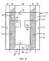
- FIG. 5is a plan view of the convective apparatus showing surface areas of varied or different permeability.
- a warming devicethat may be used perioperatively is constituted of a clinical garment and a convective apparatus with multiple sections supported on an inside surface of the garment.
- a “clinical garment”is a garment that is typically used to temporarily clothe a patient in a clinical setting. Such garments include hospital gowns, robes, bibs and other equivalents.
- the clinical settingmay be a medical or dental office or clinic, a hospital, or any facility or institution that provides medical or dental treatment to patients.
- the convective apparatushas multiple sections, preferably two separate sections. Each section may receive and distribute at least one stream of warmed pressurized air in a pneumatic structure and emit the air through at least one permeable surface to thereby convectively warm a person wearing the clinical garment. Preferably the sections emit the air through respective sections of the same permeable surface. One section is adapted for comfort warming by convection, the other for therapeutic warming by convection.
- the permeable surfaceincludes areas of different permeability.
- a warming device capable of perioperative usemay be worn on a person where it receives a first stream of warmed pressurized air in one section of the convective apparatus, distributes the pressurized air within the one section, and emits the air through a permeable surface of the one section to convectively warm the person's body for comfort.
- a warming device capable of perioperative usemay be worn on a person where it receives a second stream of warmed pressurized air in the other section of the convective apparatus, distributes the pressurized air within the other section, and emits the air through a permeable surface of the other section to convectively warm the person's body for therapy.
- the permeable surfacesare respective sections or regions of the same surface.
- the sectionsemit air through surfaces or surface regions of varied or different permeabilities.
- a sectionmay emit air through a surface with a permeability that varies over the section or that is constant over the section but different than the permeability or permeabilities of a surface through which the other section emits air.
- each of the sections of the convective apparatusis inflatable. That is, the structure of each section, flaccid when not in use, tautens when receiving a stream of pressurized air.
- the warming device 12is constituted of a clinical garment 13 and a convective apparatus 15 with multiple sections that is supported on an inside surface of the clinical garment 13 .
- the convective apparatushas for example two separate sections, each of which has at least one inlet port through which the section may receive warmed pressurized air from a heater/blower unit (not seen).
- Each inlet portis accessible through an aperture in the clinical garment 13 .
- one inlet port for one of the sectionsmay be accessed through a flap 18 in the clinical garment.
- An inlet port of another sectionmay be accessed by releasing and folding down a portion 20 of the clinical garment. This latter form of access is illustrated in FIG.
- an air hose 21 with a nozzle 23is received in an inlet port of one section of the convective apparatus 15 .
- the portion 20 of the clinical garmentcomprises a portion of the upper edge and left sleeve that may be held to an opposing portion of the clinical garment by opposing strips of hook-and-eye material.
- this other inlet portmay also be accessed through a flap such as the flap 18 instead of a folded-down garment section.
- Yet another means of accessing the inlet port for the other sectionwould be to provide perforations in the nearest sleeve.
- a full body thermal blanketis adapted to lie upon the person and to extend longitudinally along the body of the person in order to cover substantially the person's entire body, from near the ankles or feet up to the neck.
- a lower body thermal blanketis adapted to lie upon the person and to extend longitudinally along the body of a person in order to cover the person's lower body, from near the ankles or feet up to the waist or pelvis of the person.
- An upper body thermal blankethas a bow-tie shape that is adapted to lie upon and extend transversely across the upper body of a person in order to cover the person's chest and extended arms.
- thermal blanketsWhen fed a stream of warmed pressurized air, each of these thermal blankets inflates and distributes the air within itself.
- the pressurized airflows through apertures on a permeable surface of the thermal blanket which faces the person.
- thermal blanketsmay have one, two, or more inlet ports through which an air hose provides warmed pressurized air from a heater/blower unit.
- the construction of thermal blanketsis well understood. Examples of specific constructions are given in U.S. Pat. Nos. 5,620,482, 5,443,488, 5,360,439, and 5,304,213.
- convective warming productsare designed to provide a single mode of warming.
- Each of the thermal blankets described aboveis designed for therapeutic warming.
- the devices described in publication WO 03/086500are designed for comfort warming.
- the warming device described in this specificationmay provide either therapeutic warming or comfort warming, depending on the need.
- One section of the convective apparatusis constructed to receive air at low flow rates in order to provide comfort heating at steady state.
- Another sectionis constructed to receive air at higher flow rates in order to provide therapeutic heating at steady state.
- FIGS. 2A and 2BA convective apparatus 15 with multiple sections is illustrated in FIGS. 2A and 2B .
- the convective apparatus 15is shown disposed inside the outline of the clinical garment 13 ; in FIG. 2B , the convective apparatus 15 is shown in plan view looking toward a permeable surface of the convective apparatus 15 .
- the convective apparatus 15has a quadrilateral shape with a base 26 , sides 27 and top 28 which is perpendicular to the base 26 .
- the base 26 and top 28are centered on and extend transversely across a longitudinal axis 21 of the clinical garment 13 , between the sleeves 22 of the clinical garment 13 .
- the convective apparatus 15has multiple sections.
- a “section” of the convective apparatus 15is a portion or division of the convective apparatus 15 that may be inflated and operated separately from any other section of the convective apparatus 15 .
- the convective apparatus 15has a section 32 and a section 42 .
- the section 32may be inflated and operated separately from the section 42
- the section 42may be inflated and operated separately from the section 32 .
- the section 32has an inlet port 34 , an elongate transverse part 36 , and a pair of elongate parts 37 with lower ends that perpendicularly join respective ends of the transverse part 36 .
- the upper ends of the two elongate parts 37transition to transverse elongations 38 . All together, the parts 36 , 37 , and 38 form a stylized “U”.
- one inlet port 34is illustrated in the section 32 , one or more additional inlet ports may be provided for convenience. Unused inlet ports are sealed or closed by known means to prevent air escaping therethrough.
- the inlet port 34is provided through the side of the convective apparatus 15 which is not visible in this figure; it may also be provided through an edge of the convective apparatus 15 .
- the inlet port 34may comprise a collar 34 a of stiff material with an opening 34 b to receive the nozzle of an air hose, or it may comprise a sleeve of material, or any other equivalent structure.
- the space in the transverse part 36is in fluid communication with the spaces in the elongate parts 37 and the transverse elongations 38 so that pressurized air flowing through an inlet port into the transverse part 36 flows also into the elongate parts 37 and transverse elongations 38 , thereby inflating the section 32 .
- the surface of the section 32which is visible in FIGS.
- the permeability of the surface of the section 32may be constant or may vary as explained below.
- the section 42has an inlet port 44 , an elongate transverse part 46 , and a plurality of elongate parts 47 that connect perpendicularly to the transverse part 46 . All together, the transverse part 46 and the elongate parts 47 form a comb structure.
- the elongate parts 47 of the section 42are interleaved with the elongate parts 37 of the section 32 , thereby forming an integrated convective apparatus 15 with dual sections.
- one inlet port 44is illustrated in the section 42 , one or more additional inlet ports may be provided for convenience. Unused inlet ports are sealed or closed by known means to prevent air escaping therethrough.
- the inlet port 44is provided through the side of the convective apparatus 15 which is not visible in this figure; it may also be provided through an edge of the convective apparatus 15 .
- the inlet port 44may comprise a collar 44 a of stiff material with an opening 44 b to receive the nozzle of an air hose, or it may comprise a sleeve of material, or any other equivalent structure.
- the space in the transverse part 46is in fluid communication with the spaces in the elongate parts 47 so that pressurized air flowing through an inlet port into the transverse part 46 flows also into the elongate parts 47 , thereby inflating the section 42 .
- the surface of the section 42which is visible in FIGS.
- the permeability of the surface of the section 42may be constant or may vary as explained below.
- the inlet port 34 of the section 32has a smaller opening 34 b than the opening 44 b through the inlet port 44 of the section 42 . Consequently, the inlet port 34 accepts an air hose nozzle with a smaller diameter than the air hose nozzle diameter accepted by the inlet port 44 .
- the smaller nozzle diametersignifies a comfort warming air supply with an air hose having a smaller diameter than the air hose of a therapeutic warming air supply.
- the smaller air hosemay be coupled to a heater/blower unit with a smaller capacity than that of the heater blower unit of the therapeutic warming air supply.
- the smaller-diameter, smaller-capacity comfort warming air supplyensures that the section 32 operates in response to a heater/blower unit designed for comfort warming, while the larger-diameter, higher-capacity therapeutic air supply ensures that the section 42 operates in response to a heater/blower unit designed for therapeutic warming.
- FIGS. 3A and 3Billustrate assembly of a warming device suitable for perioperative use constituted of the clinical garment 13 and the convective apparatus 15 with multiple sections.
- the convective apparatus 15is adapted to be attached to, received on, supported on or constructed on the inside surface 52 of the clinical garment 13 .
- the clinical garment 13has at least one flap 18 through which an inlet port of one section may be accessed.
- the flap 18provides access to the inlet port 34 for receiving and retaining the nozzle of an air hose through which warmed pressurized air may be provided at a temperature and a capacity (in ft 3 per minute) to provide comfort warming for a person wearing the clinical garment 13 .
- the convective apparatus 15may be constructed by joining two sheets of material, one permeable to permit warmed pressurized air to be emitted through the sheet, the other impermeable.
- the impermeable sheetfaces the clinical garment 13
- the permeable sheetfaces the interior of the clinical garment 13 .
- the convective apparatus 15may be constructed as a separate piece and then attached to the inside surface 52 of the clinical garment 13 with the impermeable sheet against the inside surface 52 by tape, hook and eye material, snaps, or other equivalent structures.
- the convective apparatus 15may be constructed integrally with the clinical garment by using a portion of the clinical garment itself as one of the sheets of the convective device.
- two sheets 114 and 116 of flexible materialare joined by a single substantially continuous seal 70 along the periphery of the convective apparatus 15 , and also by continuous seal 72 that separates the sections of the convective apparatus and defines the parts of each section.
- sealsmay be made for example by sewing, gluing, heating, or ultrasonically bonding the sheets along the seals, or by combinations thereof, or by any equivalent process.
- Either or both of the sheets 114 and 116may be a single sheet or may have a laminate structure.
- a laminate sheet structuremay include a layer ( 114 a , 116 a ) of extruded synthetic material lined with a layer ( 114 b , 116 b ) of non-woven material. If the permeable sheet has a laminate structure, holes or apertures 132 are formed through both layers 114 a , 114 b of the sheet 114 to provide a permeable surface through which warmed pressurized air can be emitted toward the interior of the clinical garment 13 . In FIG.
- the sheets 114 and 116are oriented to have the extruded layers ( 114 a and 116 a ) facing, and the seals 70 , 72 are formed by a gluing process or by a heating or ultrasonic process acting through one of the layers of non-woven material.
- the convective apparatus 15may be attached to the inside surface 52 of the clinical garment by mechanisms 150 .
- the sheet 114may be a laminate structure as described above. If the clinical garment 13 is a woven cloth, such as cotton, or a non-woven such as spunbond-meltblown-spunbond material (SMS), the seals 70 , 72 between the portion of the garment's inside surface 52 and the extruded layer of the laminate sheet may be formed by a gluing, a heating, or an ultrasonic process acting between the inside surface and the sheet 114 .
- SMSspunbond-meltblown-spunbond material
- Yet another alternative construction of the convective apparatus 15is to construct the clinical garment 13 of a laminate sheet 116 and seal an apertured laminate sheet 114 or a single permeable layer 114 b of woven or non-woven material thereto.
- the convective devicemay be constituted of an impermeable layer sealed around its periphery to the outside surface of the clinical garment so that the pneumatic structure is disposed on the outside of the clinical garment.
- aperturesare provided through the portion of the clinical garment beneath the impermeable layer.
- sections of the convective devicemay be fabricated separately and placed on the inside surface 52 in the interleaved relationship shown in FIGS. 2A and 2B .
- non-woven materialexamples include any one or more of polyester, cotton, rayon, polypropylene, and wood pulp.
- extruded synthetic materialinclude polypropylene, polyesters, and polyurethanes.
- Polyolefin plastics, including polyethylene,may provide the best results in terms of manufacturability since both woven and extruded materials may be made from them.
- attachment materials and mechanisms 150 by which the convective apparatus 15 as presented in FIG. 4A can be attached to the inside surface 52include two-sided adhesive, hook and loop, sewing, snaps, heat, ultrasonic, rivets, and any and all equivalents thereof.
- the permeability of the surfaces or surface portions of the sections through which air is emittedvaries between the sections themselves. If desired, or if necessary to accommodate machines or processes with which convective devices are manufactured permeability may also vary within either or both sections.
- the permeability of the surfaces of the section adapted for comfort warmingis or is principally lower than the permeability of the section adapted for therapeutic warming.
- the permeability of the surfaces of the section adapted for therapeutic warmingis or is principally higher than the permeability of the section adapted for comfort warming. Refer to FIG. 5 for an understanding of one example of varied permeability between the sections 32 and 42 .
- FIG. 5is a plan view of the surface of the convective device 15 that faces the interior of the clinical gown 13 .
- the surface seen in FIG. 5is the surface through which the sections 32 and 42 emit air in response to inflation.
- FIG. 5is partly schematic and is intended to show not only features of the convective device 15 , but also one way in which the exemplary convective device of FIGS. 4A and 4B may be manufactured.
- the two parallel shaded strips 54represent sections or regions of a first permeability
- the wide strip 55 between the strips 54 and the two parallel strips 57 outside the strips 54represent sections or regions of a second permeability higher than the permeability of the shaded strips 54 .
- the shading in the strips 54is used only to denote a value of permeability different from the value of permeability in the non-shaded strips).
- the peripheral seal 70 and the seal 72 defining the first and second sections 32 and 42are shown with respect to the strips 54 , 55 , and 57 .
- the lower permeability in the strips 54is provided by forming holes or apertures 132 in regions of a sheet corresponding to the strips with a first mean spacing between adjacent holes or apertures, for example, ⁇ square root over (2) ⁇ inches.
- the higher permeability in the strips 55 , 57is provided by forming holes or apertures 132 in regions of a sheet corresponding to the strips with a second mean spacing between adjacent holes or apertures, for example, 1 ⁇ 2 inch.
- the greater spacingprovides a density of holes or apertures that is lower than the density of the second spacing.
- permeabilitymay be varied in a web configuration by providing different-sized spikes to form holes or apertures with uniform spacing but differing sizes.
- smaller holes or apertureswould be formed in the areas of lower permeability and larger holes or apertures in arrears of higher permeability.
- variation of both size and spacing of holes or aperturesmay be utilized to attain multiple patterns of variable permeability.
- permeability variationmay be realized in any manufacturing process capable of varying the size and/or density of the holes, apertures, interstices, ports, passageways of the material through which air is emitted in the described convective device. Such processes may include piercing the material and/or varying the composition or characteristics of the components of the material while the material is made.
- the sections 32 and 42are enabled to reach similar inflation pressures while providing substantially different rates of emission.
- Another advantage of using varied permeabilityis that warmth can be focused or concentrated on certain body portions.
- the section 32has two distribution channels 37 with low permeability in fluid communication with the comfort regions 36 and 38 protruding into the high permeability area 55 in the center of the convective device 15 .
- the clinical garment 13causes the convective device 15 to be disposed over, against, or in alignment with the center of a patient's body
- a majority of the warmed pressurized air in the comfort section 32will be emitted in these high permeability regions, thereby producing a heating effect focused on the upper thorax and legs of a patient.
- effective warmingis attained in both the clinical and therapeutic warming modes with the varied permeability configuration of FIG. 5 .
- the stylized U shape of the comfort section 32at least partially encloses the central part 47 of the therapeutic section 42 while allocating most of the higher permeability in the center of the convective device to the therapeutic warming section 42 , thereby providing sufficient heat transfer capacity for effective therapeutic warming to occur.
- enough of the high permeability in the central portion of the device 15is allocated to the comfort section 32 to warm the center of a patient's body for comfort purposes.
- the clinical garment 13may be a standard gown, a modified gown or a special purpose gown.
- the gownmay have a rear opening, a front opening or other suitable openings, such as a head opening in a poncho type gown.
- One type of gown shown in the figureshas a rear opening.
- the gown 13has a slit 170 that extends from the neck portion 154 to a hemline 155 .
- a fastening meansis provided for ease in securing the gown to the patient as well as allowing for ease in adjusting the size of the gown to accommodate various different-sized wearers.
- FIG. 3Ashows one method using hook and eye buttons 171 a , 171 b positioned along opposing sides of the slit that can be brought together and fastened to hold the gown to the patient.
- Another method attachment shown in FIG. 3Bis a plurality of strings 172 positioned along opposing sides of the slit 170 that can be tied together for holding the gown to a patient.
- Other methods of attachmentsinclude hook and eye elements, double-sided adhesive, snaps, rivets, and any and all equivalents thereof.
- the clinical garment 13may include sleeves 22 that are sized and positioned for receiving a patient's arms. Two examples of such sleeves 22 are shown in the figures.
- the sleeve portionsare slit the entire length on the shoulder or top. This allows access to the upper body of the patient and the inlet port 44 and allows for opening and closing of the slit sleeves 22 in an adjustable fashion using buttons, snaps, repositionable adhesive, hook and eye elements, double-sided adhesive, hook and loop, rivets, and any and all equivalents thereof.
- the design shown in FIG. 3Aalso facilitates the manufacturing of the clinical garment 13 in one piece.
- a personis warmed perioperatively using a warming device constituted of a clinical garment and a dual-section convective apparatus supported on an inside surface of the clinical garment by dressing a person with the clinical garment during the preoperative period, coupling a first section (the section 32 in FIG. 2B , for example) of the convective apparatus to a source of warmed pressurized air for comfort warming, and convectively warming the person for comfort by way of the first section.
- the first sectionis decoupled from the comfort warming source and the clinical garment is arranged to afford access to a surgical site.
- the clinical garmentmay be left on the person, with its skirts rolled up to provide surgical access.
- the clinical garmentmay be removed to allow the convective apparatus to be positioned on the person to provide surgical access.
- the skirts, sleeves and other loose parts of the clinical garmentmay be rolled or folded onto the convective device.
- the convective deviceif the convective device is releasably attached to the inside surface of the clinical garment, the garment may be separated from the convective device during surgery and reattached later postoperatively. During surgery, the convective device may be secured to the person by means of the double sided adhesive and a second section of the convective apparatus (for example the section 42 in FIG.
- the convective apparatusmay be coupled to a source of warmed pressurized air for therapeutic warming, and the person may be convectively warmed for therapy by way of the second section.
- the convective apparatusis detached from the person (but only if secured to the person for surgery), the convective apparatus is reattached to the clinical garment (but only if detached therefrom for surgery), the person is again dressed with the clinical garment and either warmed for comfort or warmed for therapy.
Landscapes
- Health & Medical Sciences (AREA)
- Engineering & Computer Science (AREA)
- Biomedical Technology (AREA)
- Heart & Thoracic Surgery (AREA)
- Vascular Medicine (AREA)
- Life Sciences & Earth Sciences (AREA)
- Animal Behavior & Ethology (AREA)
- General Health & Medical Sciences (AREA)
- Public Health (AREA)
- Veterinary Medicine (AREA)
- Thermotherapy And Cooling Therapy Devices (AREA)
- Professional, Industrial, Or Sporting Protective Garments (AREA)
- Cookers (AREA)
- Percussion Or Vibration Massage (AREA)
- Constitution Of High-Frequency Heating (AREA)
Abstract
Description
Claims (23)
Priority Applications (1)
| Application Number | Priority Date | Filing Date | Title |
|---|---|---|---|
| US11/801,292US7931682B2 (en) | 2004-12-07 | 2007-05-09 | Warming device with varied permeability |
Applications Claiming Priority (2)
| Application Number | Priority Date | Filing Date | Title |
|---|---|---|---|
| US11/005,883US7226454B2 (en) | 2004-12-07 | 2004-12-07 | Warming device with varied permeability |
| US11/801,292US7931682B2 (en) | 2004-12-07 | 2007-05-09 | Warming device with varied permeability |
Related Parent Applications (1)
| Application Number | Title | Priority Date | Filing Date |
|---|---|---|---|
| US11/005,883ContinuationUS7226454B2 (en) | 2004-12-07 | 2004-12-07 | Warming device with varied permeability |
Publications (2)
| Publication Number | Publication Date |
|---|---|
| US20070239239A1 US20070239239A1 (en) | 2007-10-11 |
| US7931682B2true US7931682B2 (en) | 2011-04-26 |
Family
ID=36575402
Family Applications (2)
| Application Number | Title | Priority Date | Filing Date |
|---|---|---|---|
| US11/005,883Expired - LifetimeUS7226454B2 (en) | 2004-12-07 | 2004-12-07 | Warming device with varied permeability |
| US11/801,292Active2027-09-24US7931682B2 (en) | 2004-12-07 | 2007-05-09 | Warming device with varied permeability |
Family Applications Before (1)
| Application Number | Title | Priority Date | Filing Date |
|---|---|---|---|
| US11/005,883Expired - LifetimeUS7226454B2 (en) | 2004-12-07 | 2004-12-07 | Warming device with varied permeability |
Country Status (11)
| Country | Link |
|---|---|
| US (2) | US7226454B2 (en) |
| EP (1) | EP1824431B1 (en) |
| JP (1) | JP2008522664A (en) |
| AT (1) | ATE434428T1 (en) |
| AU (1) | AU2005314264B2 (en) |
| CA (1) | CA2589865A1 (en) |
| DE (1) | DE602005015136D1 (en) |
| ES (1) | ES2327144T3 (en) |
| MX (1) | MX2007006650A (en) |
| PT (1) | PT1824431E (en) |
| WO (1) | WO2006062910A1 (en) |
Cited By (5)
| Publication number | Priority date | Publication date | Assignee | Title |
|---|---|---|---|---|
| US20100211138A1 (en)* | 2009-02-13 | 2010-08-19 | Smiths Medical Asd, Inc. | Full body split access blanket |
| US20120305541A1 (en)* | 2011-05-26 | 2012-12-06 | Giles Andrew J | Patient Warming Gown |
| US9687093B2 (en) | 2011-05-26 | 2017-06-27 | Medline Industries, Inc | Patient warming blanket, drape, and corresponding patient warming system |
| US10441006B2 (en) | 2015-12-07 | 2019-10-15 | Medline Industries, Inc. | Patient-warming gown |
| US11607337B1 (en) | 2019-10-24 | 2023-03-21 | Said Elghobashi | Recirculating-air warming blanket |
Families Citing this family (37)
| Publication number | Priority date | Publication date | Assignee | Title |
|---|---|---|---|---|
| US7766022B2 (en) | 2005-06-16 | 2010-08-03 | Eurio, Inc. | Modular system for concealment and shelter |
| US7802582B2 (en)* | 2006-07-10 | 2010-09-28 | Evrio, Inc. | System for concealment and shelter with structure for rapid setup and tight skin |
| US8056572B2 (en)* | 2001-06-04 | 2011-11-15 | Evrio, Inc. | System for rapid concealment and shelter including angular frames and warfighter covers |
| US7828038B2 (en) | 2001-06-04 | 2010-11-09 | Evrio, Inc. | Universal lightweight portable concealment means and methods |
| US7841355B2 (en)* | 2005-06-16 | 2010-11-30 | Evrio, Inc. | Modular system including shaft segments having configuration and breakdown attachments |
| US8397738B2 (en)* | 2001-06-04 | 2013-03-19 | Evrio, Inc. | Modular system for concealment and shelter |
| US8192475B2 (en)* | 2002-04-10 | 2012-06-05 | Arizant Healthcare Inc. | Warming device constructions with a poncho-type patient gown |
| EP2255759B1 (en) | 2002-04-10 | 2017-09-20 | 3M Innovative Properties Company | Patient comfort apparatus and system |
| US20050015127A1 (en)* | 2003-04-10 | 2005-01-20 | Bieberich Mark T. | Perioperative warming device |
| ATE450233T1 (en)* | 2003-09-24 | 2009-12-15 | Dynatherm Medical Inc | MEDICAL DEVICE FOR ADJUSTING THE CORE TEMPERATURE OF THE BODY |
| US8182521B2 (en)* | 2003-09-24 | 2012-05-22 | Dynatherm Medical Inc. | Methods and apparatus for increasing blood circulation |
| JP2005234988A (en)* | 2004-02-20 | 2005-09-02 | Sanyo Electric Co Ltd | Voltage generation circuit |
| US7846192B2 (en)* | 2004-12-07 | 2010-12-07 | Arizant Healthcare Inc. | Warming device |
| US7226454B2 (en)* | 2004-12-07 | 2007-06-05 | Arizant Healthcare Inc. | Warming device with varied permeability |
| US7364584B2 (en)* | 2004-12-07 | 2008-04-29 | Arizant Healthcare Inc. | Warming device |
| US7470280B2 (en)* | 2005-02-11 | 2008-12-30 | Arizant Healthcare Inc. | Clinical garment for comfort warming and prewarming |
| US8454672B2 (en)* | 2005-02-11 | 2013-06-04 | Arizant Healthcare Inc. | Warming device for perioperative use |
| US7520889B2 (en)* | 2005-02-11 | 2009-04-21 | Arizant Healthcare Inc. | Thermal blanket for warming the limbs |
| US8029502B2 (en)* | 2005-05-19 | 2011-10-04 | Endocare, Inc. | Cryosurgical probe assembly with multiple deployable cryoprobes |
| US8097031B2 (en)* | 2005-10-20 | 2012-01-17 | Arizant Healthcare Inc. | Warming device with provisions for deploying elements of an upper body convective apparatus and for deploying the lower portion of the warming device |
| AU2006304726B2 (en)* | 2005-10-20 | 2012-05-31 | 3M Innovative Properties Company | Multifunction warming device for perioperative use |
| US9308148B2 (en)* | 2006-12-04 | 2016-04-12 | Thermatx, Inc. | Methods and apparatus for adjusting blood circulation |
| US8603150B2 (en)* | 2006-12-04 | 2013-12-10 | Carefusion 2200, Inc. | Methods and apparatus for adjusting blood circulation |
| US7862599B2 (en)* | 2007-01-23 | 2011-01-04 | Arizant Healthcare Inc. | Convective warming device with a drape |
| US7976572B2 (en) | 2007-02-09 | 2011-07-12 | Arizant Healthcare Inc. | Forced air warming unit |
| US20080307567A1 (en)* | 2007-06-14 | 2008-12-18 | Stephen T Horn | Enhanced evaporative cooling system |
| US20090177184A1 (en)* | 2008-01-09 | 2009-07-09 | Christensen Scott A | Method and apparatus for improving venous access |
| US8771329B2 (en)* | 2010-01-08 | 2014-07-08 | Carefusion 2200, Inc. | Methods and apparatus for enhancing vascular access in an appendage to enhance therapeutic and interventional procedures |
| US10893709B2 (en)* | 2010-08-25 | 2021-01-19 | The Surgical Company International B.V. | Garment for preventing redistribution hypothermia |
| US9956112B2 (en) | 2010-08-30 | 2018-05-01 | The Surgical Company International B.V. | Prewarming gown |
| US10010446B2 (en) | 2011-01-05 | 2018-07-03 | Hill-Rom Services, Inc. | Cooling system for an occupant of an occupant support and a cooling garment |
| WO2013057703A1 (en)* | 2011-10-21 | 2013-04-25 | Koninklijke Philips Electronics N.V. | Body surface feedback for medical interventions |
| US20140094884A1 (en)* | 2012-10-01 | 2014-04-03 | Zaheer Zaidi | Warming system |
| WO2014092874A1 (en) | 2012-12-13 | 2014-06-19 | 3M Innovative Properties Company | Patient warming gown with peripheral warming |
| WO2015030248A1 (en)* | 2013-09-02 | 2015-03-05 | Ikk株式会社 | Production method for composite fabric equipped with fluid circuit, and composite fabric equipped with fluid circuit |
| US12268256B1 (en)* | 2019-09-17 | 2025-04-08 | B J Zarcone | Wearable fogging apparatus |
| US11819304B2 (en) | 2019-09-25 | 2023-11-21 | Welmed Inc. | Surgical draping device having a thermal feature to retain normal patient body heat |
Citations (82)
| Publication number | Priority date | Publication date | Assignee | Title |
|---|---|---|---|---|
| GB475811A (en) | 1936-05-25 | 1937-11-25 | Benjamin Hill | Heating or cooling garment |
| FR821150A (en) | 1936-05-14 | 1937-11-27 | Apparatus for the application of thermotherapy | |
| US2512559A (en) | 1945-01-18 | 1950-06-20 | Alfred L W Williams | Comfort unit |
| US2573414A (en) | 1947-03-05 | 1951-10-30 | Karl L Dunn | Hot work garment |
| US2826758A (en) | 1955-12-15 | 1958-03-18 | Kahn Alexander | Ventilated clothing and apparatus |
| US3468299A (en) | 1967-12-20 | 1969-09-23 | Carl D Amato | Air-conditioned garment |
| US3610323A (en) | 1969-10-20 | 1971-10-05 | Dan E Troyer | Cool coat |
| US3757366A (en) | 1971-08-18 | 1973-09-11 | W Sacher | Cushion for preventing and alleviating bedsores |
| US3855635A (en) | 1973-05-17 | 1974-12-24 | C Ramirez | Two piece hospital gown |
| US3911499A (en) | 1974-06-06 | 1975-10-14 | Kimberly Clark Co | Disposable medical gown |
| US3950789A (en) | 1975-07-22 | 1976-04-20 | Kansas State University Research Foundation | Dry ice cooling jacket |
| GB1462003A (en) | 1975-01-09 | 1977-01-19 | Standard Telephones Cables Ltd | Telecommunication systems |
| US4055173A (en) | 1975-04-21 | 1977-10-25 | Knab James V | Surgical masking and ventilating system |
| US4146933A (en) | 1976-07-19 | 1979-04-03 | Barry R. Jenkins | Conditioned-air suit and system |
| US4369528A (en) | 1981-02-23 | 1983-01-25 | Alba-Waldensian, Inc. | Garment for maintaining body temperature and method of making same |
| US4494248A (en) | 1982-07-22 | 1985-01-22 | Holder Percy E A | Fabu patient gown |
| US4524463A (en) | 1982-09-13 | 1985-06-25 | Ogden Danny W | Wrap around garment |
| US4558468A (en) | 1984-10-05 | 1985-12-17 | The Kendall Company | Surgical gown having one-piece-belt system |
| US4578825A (en) | 1985-07-22 | 1986-04-01 | Vote Marjean D | Smock or gown |
| US4587671A (en) | 1985-02-19 | 1986-05-13 | American Hospital Supply Corporation | Open, wraparound, sleeved garment |
| US4651727A (en) | 1983-12-20 | 1987-03-24 | Howorth Air Engineering Limited | Body exhaust gown arrangement |
| US4653120A (en) | 1985-11-22 | 1987-03-31 | Sallie Leaf | Hospital-type gown with front and rear openings |
| US4696066A (en) | 1986-09-15 | 1987-09-29 | Ball Joyce A | Heated coat liner |
| US4718124A (en) | 1987-01-13 | 1988-01-12 | Sawicki Marsha M | Patient gown |
| US4787101A (en) | 1984-08-15 | 1988-11-29 | Alixandra Feinberg | Garment for convalescents |
| US4914752A (en) | 1989-01-27 | 1990-04-10 | Abandaco, Inc. | Temperature-regulated garment utilizing a vortex tube |
| US4964282A (en) | 1989-12-07 | 1990-10-23 | Wagner Christopher S | Detachable bulletproof vest air conditioning apparatus |
| US5062424A (en) | 1991-01-24 | 1991-11-05 | The University Of North Carolina At Chapel Hill | Portable apparatus for rapid reduction of elevated body core temperature |
| US5190031A (en) | 1991-03-11 | 1993-03-02 | Raul Guibert | Universal thermotherapy applicator |
| US5255390A (en) | 1992-12-03 | 1993-10-26 | Chem-Tex Corporation | Gas ventilated garment having a low gas consumption valving configuration |
| US5304213A (en) | 1993-06-14 | 1994-04-19 | Cincinnati Sub-Zero Products, Inc. | Hyper-hypothermia blanket with filtration properties |
| US5360439A (en) | 1992-08-03 | 1994-11-01 | Mallinckrodt Medical, Inc. | Warming blanket method utilizing a warming blanket having multiple inlets |
| US5367710A (en) | 1993-01-12 | 1994-11-29 | Karmin; James L. | Medical gown for preserving privacy |
| US5411541A (en) | 1993-08-05 | 1995-05-02 | Oansh Designs Ltd. | Portable fluid therapy device |
| US5443488A (en) | 1994-08-15 | 1995-08-22 | Progressive Dynamics, Inc. | Thermal blanket with surgical access |
| US5572742A (en) | 1995-04-06 | 1996-11-12 | Vansur Investments & Asociados | Garment for the disabled |
| US5575006A (en) | 1994-12-05 | 1996-11-19 | Wolfe; Dorothy T. | Hospital privacy garment |
| US5611087A (en) | 1995-08-31 | 1997-03-18 | Adkins; Lola | Separable garment |
| US5620482A (en) | 1987-10-05 | 1997-04-15 | Augustine Medical, Inc. | Inflatable thermal blanket with a foot drape |
| WO1997014381A1 (en) | 1995-10-18 | 1997-04-24 | Mallinckrodt Medical, Inc. | Inflatable blanket having selective airflow patterns |
| US5675848A (en) | 1995-10-18 | 1997-10-14 | Mallinckrodt Medical, Inc. | Inflatable blanket having perforations of different sizes |
| US5697963A (en) | 1995-12-20 | 1997-12-16 | Augustine Medical, Inc. | Thermal blanket for a patient sitting in a chair |
| US5733318A (en) | 1994-09-30 | 1998-03-31 | Augustine Medical, Inc. | Convertible thermal blanket |
| US5749109A (en) | 1995-10-18 | 1998-05-12 | Mallinckrodt Medical, Inc. | Inflatable blanket having selective air flow patterns |
| US5785716A (en) | 1996-05-09 | 1998-07-28 | Bayron; Harry | Temperature control pad for use during medical and surgical procedures |
| WO1998048652A1 (en) | 1997-05-01 | 1998-11-05 | Oceaneering International, Inc. | An article comprising a garment or other textile structure for use in controlling body temperature |
| US5891187A (en) | 1996-05-09 | 1999-04-06 | Winthrop; Neil | Temperature control pad for use during medical and surgical procedures |
| US5946722A (en) | 1997-05-28 | 1999-09-07 | Trautmann; Charlotte B. | Patient privacy gown |
| US5970519A (en) | 1998-02-20 | 1999-10-26 | Weber; Stanley | Air cooling garment for medical personnel |
| US6049907A (en) | 1998-01-26 | 2000-04-18 | Allegiance Corporation | Gown tie |
| US6156058A (en) | 1994-01-26 | 2000-12-05 | Mallinckrodt Inc. | Warming blanket for pediatric use |
| US6154883A (en) | 1998-07-09 | 2000-12-05 | Thy Enterprises, Inc. | Garment for wear following thoracic surgery |
| US6203567B1 (en) | 1997-06-02 | 2001-03-20 | Augustine Medical, Inc. | Surgical barrier device incorporating an inflatable thermal blanket with a surgical drape to provide thermal control and surgical access |
| US6216270B1 (en) | 2000-03-10 | 2001-04-17 | Gary J. Moquin | Patient garment having enhanced accessibility |
| US6235659B1 (en) | 1997-12-08 | 2001-05-22 | Ethicon, Inc. | Medical linen with regionally imprinted performance areas |
| US6378136B2 (en) | 2000-04-27 | 2002-04-30 | Uni-Charm Corporation | Disposable gown |
| US6484321B1 (en) | 2001-05-04 | 2002-11-26 | Ronnye B. Shamam | Multi-purpose patient hospital gown |
| US6511501B1 (en) | 1998-07-21 | 2003-01-28 | Augustine Medical, Inc. | Inflatable thermal pad with drainage |
| US6551347B1 (en) | 1988-09-28 | 2003-04-22 | Life Enhancement Technologies, Inc. | Cooling/heating system |
| US6571574B1 (en) | 2000-06-21 | 2003-06-03 | Ralf W. Blackstone | Air cooling device |
| US20030126668A1 (en) | 2002-01-10 | 2003-07-10 | Scroggins Georgia W. | Hospital dressing gown construction |
| US6596019B2 (en) | 2001-08-30 | 2003-07-22 | Nike International Ltd. | Apparel ventilation system |
| US6647552B1 (en) | 2003-02-05 | 2003-11-18 | Guided Inspiration, Inc. | Medical dignity garment |
| WO2004004500A1 (en) | 2002-07-03 | 2004-01-15 | Mölnlycke Health Care Ab | Heat-emitting patient garment |
| WO2003086500A3 (en) | 2002-04-10 | 2004-02-05 | Arizant Healthcare Inc | Patient comfort apparatus and system |
| US6694522B1 (en) | 2003-04-08 | 2004-02-24 | Jay G. Neal | Universal hospital gown |
| WO2003106897A3 (en) | 2002-06-14 | 2004-06-10 | Ralf W Blackstone | An air cooling device |
| US6792622B2 (en) | 2002-03-14 | 2004-09-21 | Stephen K. Graves | Patient garments |
| US6799332B2 (en) | 1999-11-01 | 2004-10-05 | Richard L. Hatton | Two-piece patient examination garment |
| US6820622B1 (en) | 2002-06-07 | 2004-11-23 | Leonides Y. Teves | Thermal surgical drape |
| US20050015127A1 (en) | 2003-04-10 | 2005-01-20 | Bieberich Mark T. | Perioperative warming device |
| US6851125B2 (en) | 2001-01-19 | 2005-02-08 | Uni-Charm Corporation | Disposable surgical gown |
| US6876884B2 (en) | 2003-04-10 | 2005-04-05 | Arizant Healthcare Inc. | Forced air warming unit |
| US20060122672A1 (en) | 2004-12-07 | 2006-06-08 | Anderson Thomas P | Warming device |
| US20060122671A1 (en) | 2004-12-07 | 2006-06-08 | Albrecht Mark C | Warming device with varied permeability |
| US20060184218A1 (en) | 2005-02-11 | 2006-08-17 | Bieberich Mark T | Clinical garment for comfort warming and prewarming |
| US20060184216A1 (en) | 2005-02-11 | 2006-08-17 | Van Duren Albert P | Thermal blanket for warming the limbs |
| US20060184217A1 (en) | 2005-02-11 | 2006-08-17 | Van Duren Albert P | Warming device for perioperative use |
| US20060259104A1 (en) | 2004-12-07 | 2006-11-16 | Panser Carol J | Warming device |
| US20070093882A1 (en) | 2005-10-20 | 2007-04-26 | Arizant Healthcare Inc. | Multifunction warming device for perioperative use |
| US20080177361A1 (en) | 2007-01-23 | 2008-07-24 | Arizant Healthcare Inc. | Convective warming device with a drape |
| US20090228083A1 (en) | 2005-10-20 | 2009-09-10 | Arizant Healthcare Inc. | Warming device with provisions for deploying elements of an upper body convective apparatus and for deploying the lower portion of the warming device |
Family Cites Families (11)
| Publication number | Priority date | Publication date | Assignee | Title |
|---|---|---|---|---|
| US3738367A (en)* | 1971-02-11 | 1973-06-12 | Angelica Corp | Patient garment with temperature control |
| GB1462033A (en) | 1973-01-19 | 1977-01-19 | Secr Defence | Apparatus for 0ntrolling the temperature of the human body |
| ES2029888T3 (en)* | 1987-10-05 | 1992-10-01 | Augustine Medical, Inc. | A THERMAL COVER. |
| US5405370A (en)* | 1991-11-08 | 1995-04-11 | Irani; Feraidoon | Air blanket |
| SE9704870D0 (en)* | 1997-12-22 | 1997-12-22 | Astra Ab | New pharmaceutical formulation I |
| JP2000288007A (en)* | 1999-04-01 | 2000-10-17 | Art Heaven Nine:Kk | Body temperature adjusting clothes |
| IL129465A (en) | 1999-04-15 | 2005-03-20 | M T R E Advanced Technology Lt | Heat exchanger garment |
| IL131834A0 (en)* | 1999-09-09 | 2001-03-19 | M T R E Advanced Technology Lt | Method and system for improving cardiac output of a patient |
| CN1245523C (en)* | 2001-07-14 | 2006-03-15 | 昆虫生命工学株式会社 | Process for producing leather using protease and process for treating waste from leather processing using it |
| US6692518B2 (en)* | 2002-02-27 | 2004-02-17 | Medivance Incorporated | Patient temperature control system |
| CN100478464C (en) | 2004-07-20 | 2009-04-15 | Bhp比尔顿有限公司 | Tank bioleaching method |
- 2004
- 2004-12-07USUS11/005,883patent/US7226454B2/ennot_activeExpired - Lifetime
- 2005
- 2005-12-06AUAU2005314264Apatent/AU2005314264B2/ennot_activeCeased
- 2005-12-06CACA002589865Apatent/CA2589865A1/ennot_activeAbandoned
- 2005-12-06MXMX2007006650Apatent/MX2007006650A/enactiveIP Right Grant
- 2005-12-06JPJP2007544600Apatent/JP2008522664A/enactivePending
- 2005-12-06DEDE602005015136Tpatent/DE602005015136D1/enactiveActive
- 2005-12-06ATAT05853005Tpatent/ATE434428T1/enactive
- 2005-12-06PTPT05853005Tpatent/PT1824431E/enunknown
- 2005-12-06WOPCT/US2005/043968patent/WO2006062910A1/enactiveApplication Filing
- 2005-12-06EPEP05853005Apatent/EP1824431B1/ennot_activeNot-in-force
- 2005-12-06ESES05853005Tpatent/ES2327144T3/enactiveActive
- 2007
- 2007-05-09USUS11/801,292patent/US7931682B2/enactiveActive
Patent Citations (105)
| Publication number | Priority date | Publication date | Assignee | Title |
|---|---|---|---|---|
| FR821150A (en) | 1936-05-14 | 1937-11-27 | Apparatus for the application of thermotherapy | |
| GB475811A (en) | 1936-05-25 | 1937-11-25 | Benjamin Hill | Heating or cooling garment |
| US2512559A (en) | 1945-01-18 | 1950-06-20 | Alfred L W Williams | Comfort unit |
| US2573414A (en) | 1947-03-05 | 1951-10-30 | Karl L Dunn | Hot work garment |
| US2826758A (en) | 1955-12-15 | 1958-03-18 | Kahn Alexander | Ventilated clothing and apparatus |
| US3468299A (en) | 1967-12-20 | 1969-09-23 | Carl D Amato | Air-conditioned garment |
| US3610323A (en) | 1969-10-20 | 1971-10-05 | Dan E Troyer | Cool coat |
| US3757366A (en) | 1971-08-18 | 1973-09-11 | W Sacher | Cushion for preventing and alleviating bedsores |
| US3855635A (en) | 1973-05-17 | 1974-12-24 | C Ramirez | Two piece hospital gown |
| US3911499A (en) | 1974-06-06 | 1975-10-14 | Kimberly Clark Co | Disposable medical gown |
| GB1462003A (en) | 1975-01-09 | 1977-01-19 | Standard Telephones Cables Ltd | Telecommunication systems |
| US4055173A (en) | 1975-04-21 | 1977-10-25 | Knab James V | Surgical masking and ventilating system |
| US3950789A (en) | 1975-07-22 | 1976-04-20 | Kansas State University Research Foundation | Dry ice cooling jacket |
| US4146933A (en) | 1976-07-19 | 1979-04-03 | Barry R. Jenkins | Conditioned-air suit and system |
| US4369528A (en) | 1981-02-23 | 1983-01-25 | Alba-Waldensian, Inc. | Garment for maintaining body temperature and method of making same |
| US4494248A (en) | 1982-07-22 | 1985-01-22 | Holder Percy E A | Fabu patient gown |
| US4524463A (en) | 1982-09-13 | 1985-06-25 | Ogden Danny W | Wrap around garment |
| US4651727A (en) | 1983-12-20 | 1987-03-24 | Howorth Air Engineering Limited | Body exhaust gown arrangement |
| US4787101A (en) | 1984-08-15 | 1988-11-29 | Alixandra Feinberg | Garment for convalescents |
| US4558468A (en) | 1984-10-05 | 1985-12-17 | The Kendall Company | Surgical gown having one-piece-belt system |
| US4587671A (en) | 1985-02-19 | 1986-05-13 | American Hospital Supply Corporation | Open, wraparound, sleeved garment |
| US4578825A (en) | 1985-07-22 | 1986-04-01 | Vote Marjean D | Smock or gown |
| US4653120A (en) | 1985-11-22 | 1987-03-31 | Sallie Leaf | Hospital-type gown with front and rear openings |
| US4696066A (en) | 1986-09-15 | 1987-09-29 | Ball Joyce A | Heated coat liner |
| US4718124A (en) | 1987-01-13 | 1988-01-12 | Sawicki Marsha M | Patient gown |
| US5620482A (en) | 1987-10-05 | 1997-04-15 | Augustine Medical, Inc. | Inflatable thermal blanket with a foot drape |
| US6524332B1 (en) | 1987-10-05 | 2003-02-25 | Augustine Medical, Inc. | System and method for warming a person to prevent or treat hypothermia |
| US6551347B1 (en) | 1988-09-28 | 2003-04-22 | Life Enhancement Technologies, Inc. | Cooling/heating system |
| US4914752A (en) | 1989-01-27 | 1990-04-10 | Abandaco, Inc. | Temperature-regulated garment utilizing a vortex tube |
| US4964282A (en) | 1989-12-07 | 1990-10-23 | Wagner Christopher S | Detachable bulletproof vest air conditioning apparatus |
| US5062424A (en) | 1991-01-24 | 1991-11-05 | The University Of North Carolina At Chapel Hill | Portable apparatus for rapid reduction of elevated body core temperature |
| US5190031A (en) | 1991-03-11 | 1993-03-02 | Raul Guibert | Universal thermotherapy applicator |
| US5360439A (en) | 1992-08-03 | 1994-11-01 | Mallinckrodt Medical, Inc. | Warming blanket method utilizing a warming blanket having multiple inlets |
| US5974605A (en) | 1992-08-03 | 1999-11-02 | Mallinckrodt Inc. | Warming blanket having multiple inlets |
| US5255390A (en) | 1992-12-03 | 1993-10-26 | Chem-Tex Corporation | Gas ventilated garment having a low gas consumption valving configuration |
| US5367710A (en) | 1993-01-12 | 1994-11-29 | Karmin; James L. | Medical gown for preserving privacy |
| US5304213A (en) | 1993-06-14 | 1994-04-19 | Cincinnati Sub-Zero Products, Inc. | Hyper-hypothermia blanket with filtration properties |
| US5411541A (en) | 1993-08-05 | 1995-05-02 | Oansh Designs Ltd. | Portable fluid therapy device |
| US6156058A (en) | 1994-01-26 | 2000-12-05 | Mallinckrodt Inc. | Warming blanket for pediatric use |
| US5443488A (en) | 1994-08-15 | 1995-08-22 | Progressive Dynamics, Inc. | Thermal blanket with surgical access |
| US5733318A (en) | 1994-09-30 | 1998-03-31 | Augustine Medical, Inc. | Convertible thermal blanket |
| US5575006A (en) | 1994-12-05 | 1996-11-19 | Wolfe; Dorothy T. | Hospital privacy garment |
| US5572742A (en) | 1995-04-06 | 1996-11-12 | Vansur Investments & Asociados | Garment for the disabled |
| US5611087A (en) | 1995-08-31 | 1997-03-18 | Adkins; Lola | Separable garment |
| US5675848A (en) | 1995-10-18 | 1997-10-14 | Mallinckrodt Medical, Inc. | Inflatable blanket having perforations of different sizes |
| US5749109A (en) | 1995-10-18 | 1998-05-12 | Mallinckrodt Medical, Inc. | Inflatable blanket having selective air flow patterns |
| WO1997014381A1 (en) | 1995-10-18 | 1997-04-24 | Mallinckrodt Medical, Inc. | Inflatable blanket having selective airflow patterns |
| US5697963A (en) | 1995-12-20 | 1997-12-16 | Augustine Medical, Inc. | Thermal blanket for a patient sitting in a chair |
| US5891187A (en) | 1996-05-09 | 1999-04-06 | Winthrop; Neil | Temperature control pad for use during medical and surgical procedures |
| US5785716A (en) | 1996-05-09 | 1998-07-28 | Bayron; Harry | Temperature control pad for use during medical and surgical procedures |
| WO1998048652A1 (en) | 1997-05-01 | 1998-11-05 | Oceaneering International, Inc. | An article comprising a garment or other textile structure for use in controlling body temperature |
| US5946722A (en) | 1997-05-28 | 1999-09-07 | Trautmann; Charlotte B. | Patient privacy gown |
| US6203567B1 (en) | 1997-06-02 | 2001-03-20 | Augustine Medical, Inc. | Surgical barrier device incorporating an inflatable thermal blanket with a surgical drape to provide thermal control and surgical access |
| US6235659B1 (en) | 1997-12-08 | 2001-05-22 | Ethicon, Inc. | Medical linen with regionally imprinted performance areas |
| US6049907A (en) | 1998-01-26 | 2000-04-18 | Allegiance Corporation | Gown tie |
| US5970519A (en) | 1998-02-20 | 1999-10-26 | Weber; Stanley | Air cooling garment for medical personnel |
| US6154883A (en) | 1998-07-09 | 2000-12-05 | Thy Enterprises, Inc. | Garment for wear following thoracic surgery |
| US6511501B1 (en) | 1998-07-21 | 2003-01-28 | Augustine Medical, Inc. | Inflatable thermal pad with drainage |
| US6799332B2 (en) | 1999-11-01 | 2004-10-05 | Richard L. Hatton | Two-piece patient examination garment |
| US6216270B1 (en) | 2000-03-10 | 2001-04-17 | Gary J. Moquin | Patient garment having enhanced accessibility |
| US6378136B2 (en) | 2000-04-27 | 2002-04-30 | Uni-Charm Corporation | Disposable gown |
| US6571574B1 (en) | 2000-06-21 | 2003-06-03 | Ralf W. Blackstone | Air cooling device |
| US6851125B2 (en) | 2001-01-19 | 2005-02-08 | Uni-Charm Corporation | Disposable surgical gown |
| US6484321B1 (en) | 2001-05-04 | 2002-11-26 | Ronnye B. Shamam | Multi-purpose patient hospital gown |
| US6596019B2 (en) | 2001-08-30 | 2003-07-22 | Nike International Ltd. | Apparel ventilation system |
| US20030126668A1 (en) | 2002-01-10 | 2003-07-10 | Scroggins Georgia W. | Hospital dressing gown construction |
| US6792622B2 (en) | 2002-03-14 | 2004-09-21 | Stephen K. Graves | Patient garments |
| US7001416B2 (en) | 2002-04-10 | 2006-02-21 | Arizant Healthcare Inc. | Patient comfort apparatus and system |
| WO2003086500A3 (en) | 2002-04-10 | 2004-02-05 | Arizant Healthcare Inc | Patient comfort apparatus and system |
| US20050143796A1 (en) | 2002-04-10 | 2005-06-30 | Augustine Scott D. | Patient comfort apparatus and system |
| US6820622B1 (en) | 2002-06-07 | 2004-11-23 | Leonides Y. Teves | Thermal surgical drape |
| WO2003106897A3 (en) | 2002-06-14 | 2004-06-10 | Ralf W Blackstone | An air cooling device |
| SE525415C2 (en) | 2002-07-03 | 2005-02-15 | Moelnlycke Health Care Ab | Heat-emitting patient costume |
| WO2004004500A1 (en) | 2002-07-03 | 2004-01-15 | Mölnlycke Health Care Ab | Heat-emitting patient garment |
| US20060047332A1 (en) | 2002-07-03 | 2006-03-02 | Angelica Malmberg | Heat-emitting patient garment |
| US6647552B1 (en) | 2003-02-05 | 2003-11-18 | Guided Inspiration, Inc. | Medical dignity garment |
| US6694522B1 (en) | 2003-04-08 | 2004-02-24 | Jay G. Neal | Universal hospital gown |
| US20060147320A1 (en) | 2003-04-10 | 2006-07-06 | Hansen Gary L | Forced air warming unit |
| US20050015127A1 (en) | 2003-04-10 | 2005-01-20 | Bieberich Mark T. | Perioperative warming device |
| US6876884B2 (en) | 2003-04-10 | 2005-04-05 | Arizant Healthcare Inc. | Forced air warming unit |
| WO2006020170A1 (en) | 2004-07-21 | 2006-02-23 | Arizant Healthcare Inc. | Perioperative warming device |
| US7276076B2 (en) | 2004-07-21 | 2007-10-02 | Arizant Healthcare Inc. | Perioperative warming device |
| US20080027521A1 (en) | 2004-07-21 | 2008-01-31 | Arizant Healthcare Inc. | Perioperative warming device |
| US20080027522A1 (en) | 2004-07-21 | 2008-01-31 | Arizant Healthcare Inc. | Perioperative warming method |
| US20080125840A1 (en) | 2004-12-07 | 2008-05-29 | Arizant Healthcare Inc. | Warming device |
| US20060122672A1 (en) | 2004-12-07 | 2006-06-08 | Anderson Thomas P | Warming device |
| US7364584B2 (en) | 2004-12-07 | 2008-04-29 | Arizant Healthcare Inc. | Warming device |
| WO2006062910A1 (en) | 2004-12-07 | 2006-06-15 | Arizant Healthcare Inc. | Warming device with varied permeability |
| US20060259104A1 (en) | 2004-12-07 | 2006-11-16 | Panser Carol J | Warming device |
| US20090149931A9 (en) | 2004-12-07 | 2009-06-11 | Arizant Healthcare Inc. | Warming device |
| WO2006063027A1 (en) | 2004-12-07 | 2006-06-15 | Arizant Healthcare Inc | Warming device |
| US20070239239A1 (en) | 2004-12-07 | 2007-10-11 | Arizant Healthcare Inc. | Warming device with varied permeability |
| US20060122671A1 (en) | 2004-12-07 | 2006-06-08 | Albrecht Mark C | Warming device with varied permeability |
| US7226454B2 (en) | 2004-12-07 | 2007-06-05 | Arizant Healthcare Inc. | Warming device with varied permeability |
| US7470280B2 (en) | 2005-02-11 | 2008-12-30 | Arizant Healthcare Inc. | Clinical garment for comfort warming and prewarming |
| US20090062891A1 (en) | 2005-02-11 | 2009-03-05 | Arizant Healthcare Inc. | Clinical garment for comfort warming and prewarming |
| US20060184218A1 (en) | 2005-02-11 | 2006-08-17 | Bieberich Mark T | Clinical garment for comfort warming and prewarming |
| US20060184217A1 (en) | 2005-02-11 | 2006-08-17 | Van Duren Albert P | Warming device for perioperative use |
| US20060184216A1 (en) | 2005-02-11 | 2006-08-17 | Van Duren Albert P | Thermal blanket for warming the limbs |
| US20070093884A1 (en) | 2005-10-20 | 2007-04-26 | Arizant Healthcare Inc. | Multifunction warming device with provision for warming hands |
| US20070093883A1 (en) | 2005-10-20 | 2007-04-26 | Arizant Healthcare Inc. | Multifunction warming device with provision for being secured |
| US20070093885A1 (en) | 2005-10-20 | 2007-04-26 | Arizant Healthcare Inc. | Multifunction warming device with an upper body convective apparatus |
| US20070093882A1 (en) | 2005-10-20 | 2007-04-26 | Arizant Healthcare Inc. | Multifunction warming device for perioperative use |
| US20090228083A1 (en) | 2005-10-20 | 2009-09-10 | Arizant Healthcare Inc. | Warming device with provisions for deploying elements of an upper body convective apparatus and for deploying the lower portion of the warming device |
| US20080177361A1 (en) | 2007-01-23 | 2008-07-24 | Arizant Healthcare Inc. | Convective warming device with a drape |
Non-Patent Citations (24)
| Title |
|---|
| Applicant's Response to Examination Report in EP05853005.6, mailed May 1, 2008. |
| C.B. Mahony & J. Odom, Maintaining intraoperative normothermia: A meta-analysis of outcomes with costs. AANA Journal. Apr. 1999. vol. 67, No. 2:155-164. |
| EPO Examination Report mailed Apr. 14, 2010 in EP06826351.6, EP Regional Phase of PCT/US2006/041028 (published as WO/2007/047917). |
| EPO Examination Report mailed Apr. 24, 2009, in EP06826351.6, EP Regional Phase of PCT/US2006/041028 (published as WO/2007/047917). |
| EPO Examination Report mailed Dec. 17, 2007, in EPO3719690.4-1526, EP Regional Phase of PCT/US2003/11128 (published as WO/2003/086500). |
| EPO Examination Report mailed Jan. 23, 2009, in EP05853202, EP Regional Phase of PCT/US2005/044214 (published as WO/2006/063027). |
| EPO Examination Report mailed Jan. 8, 2008, in EP05853005.6, EP Regional Phase of PCT/US2005/043968 (published as WO/2006/062910). |
| EPO Examination Report mailed Jun. 22, 2009, in EP05853202.9, EP Regional Phase of PCT/US2005/044214 (published as WO/2006/063027). |
| EPO Examination Report mailed Oct. 24, 2006, in EPO3719690.4-1526, EP Regional Phase of PCT/US2003/11128 (published as WO/2003/086500). |
| EPO Examination Report mailed Sep. 2, 2008, in EP05789978.3, EP Regional Phase of PCT/US2005/025355 (published as WO/2006/020170). |
| EPO Examination Report mailed Sep. 29, 2009, in EP06720577.3, EP Regional Phase of PCT/US2006/004644 (published as WO/2006/086587). |
| EPO Examination Report mailed Sep. 3, 2009 in EP 07795671.2, EP Regional Phase of PCT/US2007/013073 (published as WO/2008/013603). |
| International Search Report and Written Opinion in PCT/US2005/025355, mailed Dec. 1, 2005. |
| International Search Report and Written Opinion in PCT/US2005/043968, mailed Apr. 19, 2006. |
| International Search Report and Written Opinion in PCT/US2005/044214, mailed Apr. 19, 2006. |
| International Search Report and Written Opinion in PCT/US2007/013073, mailed Nov. 9, 2007. |
| International Search Report and Written Opinion in PCT/US2008/000141, mailed Nov. 11, 2008. |
| International Search Report in PCT/US2006/004644, mailed Dec. 18, 2006. |
| International Search Report in PCT/US2006/041028, mailed Feb. 20, 2007. |
| P.O. Fanger, Thermal Comfort: Analysis and Applications in Environmental Engineering, Danish Technical Press, 1970, pp. 5-67. |
| Porta-Chill-The Portable Air-Chiller-Brochure, http://www.portachil.com/, Dec. 3, 2002. |
| Porta-Chill—The Portable Air-Chiller—Brochure, http://www.portachil.com/, Dec. 3, 2002. |
| Written Opinion of the International Search Authority (EPO) in PCT/US2006/004644, mailed Dec. 18, 2006. |
| Written Opinion of the International Search Authority (EPO) in PCT/US2006/041028, mailed Feb. 20, 2007. |
Cited By (8)
| Publication number | Priority date | Publication date | Assignee | Title |
|---|---|---|---|---|
| US20100211138A1 (en)* | 2009-02-13 | 2010-08-19 | Smiths Medical Asd, Inc. | Full body split access blanket |
| US8197525B2 (en)* | 2009-02-13 | 2012-06-12 | Smiths Medical Asd, Inc. | Full body split access blanket |
| US20120305541A1 (en)* | 2011-05-26 | 2012-12-06 | Giles Andrew J | Patient Warming Gown |
| US9642404B2 (en)* | 2011-05-26 | 2017-05-09 | Medline Industries, Inc. | Patient warming gown |
| US9687093B2 (en) | 2011-05-26 | 2017-06-27 | Medline Industries, Inc | Patient warming blanket, drape, and corresponding patient warming system |
| US10441006B2 (en) | 2015-12-07 | 2019-10-15 | Medline Industries, Inc. | Patient-warming gown |
| US11178920B2 (en) | 2015-12-07 | 2021-11-23 | Medline Industries, Lp | Patient-warming gown |
| US11607337B1 (en) | 2019-10-24 | 2023-03-21 | Said Elghobashi | Recirculating-air warming blanket |
Also Published As
| Publication number | Publication date |
|---|---|
| WO2006062910A1 (en) | 2006-06-15 |
| DE602005015136D1 (en) | 2009-08-06 |
| EP1824431B1 (en) | 2009-06-24 |
| PT1824431E (en) | 2009-08-31 |
| AU2005314264A1 (en) | 2006-06-15 |
| CA2589865A1 (en) | 2006-06-15 |
| ES2327144T3 (en) | 2009-10-26 |
| JP2008522664A (en) | 2008-07-03 |
| MX2007006650A (en) | 2007-07-25 |
| US20060122671A1 (en) | 2006-06-08 |
| ATE434428T1 (en) | 2009-07-15 |
| US7226454B2 (en) | 2007-06-05 |
| EP1824431A1 (en) | 2007-08-29 |
| AU2005314264B2 (en) | 2010-04-29 |
| US20070239239A1 (en) | 2007-10-11 |
Similar Documents
| Publication | Publication Date | Title |
|---|---|---|
| US7931682B2 (en) | Warming device with varied permeability | |
| US8043350B2 (en) | Warming device | |
| CA2658380C (en) | Warming device | |
| US7276076B2 (en) | Perioperative warming device |
Legal Events
| Date | Code | Title | Description |
|---|---|---|---|
| AS | Assignment | Owner name:GENERAL ELECTRIC CAPITAL CORPORATION,AS ADMINISTRA Free format text:SECURITY AGREEMENT;ASSIGNOR:ARIZANT HEALTHCARE INC.;REEL/FRAME:022813/0114 Effective date:20090611 | |
| AS | Assignment | Owner name:GENERAL ELECTRIC CAPITAL CORPORATION, MARYLAND Free format text:ASSIGNMENT OF ASSIGNORS INTEREST;ASSIGNOR:ARIZANT HEALTHCARE INC.;REEL/FRAME:025137/0066 Effective date:20101013 | |
| AS | Assignment | Owner name:ARIZANT HEALTHCARE INC., MINNESOTA Free format text:CORRECTIVE ASSIGNMENT TO CORRECT THE NATURE OF THE CONVEYANCE AS A RELEASE BY SECURED PARTY, AND THE IDENTITY OF THE ASSIGNOR AND ASSIGNEE PREVIOUSLY RECORDED ON REEL 025137 FRAME 0066. ASSIGNOR(S) HEREBY CONFIRMS THE RELEASE OF SECURITY INTEREST IN ALL OF GRANTOR'S RIGHT, TITLE AND INTEREST IN PATENT RIGHTS;ASSIGNOR:GENERAL ELECTRIC CAPITAL CORPORATION, AS ADMINISTRATIVE AGENT;REEL/FRAME:025444/0901 Effective date:20101013 | |
| STCF | Information on status: patent grant | Free format text:PATENTED CASE | |
| CC | Certificate of correction | ||
| AS | Assignment | Owner name:3M INNOVATIVE PROPERTIES COMPANY, MINNESOTA Free format text:ASSIGNMENT OF ASSIGNORS INTEREST;ASSIGNOR:ARIZANT HEALTHCARE INC.;REEL/FRAME:032040/0362 Effective date:20131212 | |
| FPAY | Fee payment | Year of fee payment:4 | |
| MAFP | Maintenance fee payment | Free format text:PAYMENT OF MAINTENANCE FEE, 8TH YEAR, LARGE ENTITY (ORIGINAL EVENT CODE: M1552); ENTITY STATUS OF PATENT OWNER: LARGE ENTITY Year of fee payment:8 | |
| MAFP | Maintenance fee payment | Free format text:PAYMENT OF MAINTENANCE FEE, 12TH YEAR, LARGE ENTITY (ORIGINAL EVENT CODE: M1553); ENTITY STATUS OF PATENT OWNER: LARGE ENTITY Year of fee payment:12 | |
| AS | Assignment | Owner name:SOLVENTUM INTELLECTUAL PROPERTIES COMPANY, MINNESOTA Free format text:ASSIGNMENT OF ASSIGNORS INTEREST;ASSIGNOR:3M INNOVATIVE PROPERTIES COMPANY;REEL/FRAME:066430/0287 Effective date:20240201 |