US7931675B2 - Dynamic stabilization device including overhanging stabilizing member - Google Patents
Dynamic stabilization device including overhanging stabilizing memberDownload PDFInfo
- Publication number
- US7931675B2 US7931675B2US11/159,471US15947105AUS7931675B2US 7931675 B2US7931675 B2US 7931675B2US 15947105 AUS15947105 AUS 15947105AUS 7931675 B2US7931675 B2US 7931675B2
- Authority
- US
- United States
- Prior art keywords
- attachment member
- stabilization device
- elongate element
- respect
- resilient
- Prior art date
- Legal status (The legal status is an assumption and is not a legal conclusion. Google has not performed a legal analysis and makes no representation as to the accuracy of the status listed.)
- Active, expires
Links
Images


Classifications
- A—HUMAN NECESSITIES
- A61—MEDICAL OR VETERINARY SCIENCE; HYGIENE
- A61B—DIAGNOSIS; SURGERY; IDENTIFICATION
- A61B17/00—Surgical instruments, devices or methods
- A61B17/56—Surgical instruments or methods for treatment of bones or joints; Devices specially adapted therefor
- A61B17/58—Surgical instruments or methods for treatment of bones or joints; Devices specially adapted therefor for osteosynthesis, e.g. bone plates, screws or setting implements
- A61B17/68—Internal fixation devices, including fasteners and spinal fixators, even if a part thereof projects from the skin
- A61B17/70—Spinal positioners or stabilisers, e.g. stabilisers comprising fluid filler in an implant
- A61B17/7001—Screws or hooks combined with longitudinal elements which do not contact vertebrae
- A61B17/7002—Longitudinal elements, e.g. rods
- A61B17/7019—Longitudinal elements having flexible parts, or parts connected together, such that after implantation the elements can move relative to each other
- A61B17/7026—Longitudinal elements having flexible parts, or parts connected together, such that after implantation the elements can move relative to each other with a part that is flexible due to its form
- A—HUMAN NECESSITIES
- A61—MEDICAL OR VETERINARY SCIENCE; HYGIENE
- A61B—DIAGNOSIS; SURGERY; IDENTIFICATION
- A61B17/00—Surgical instruments, devices or methods
- A61B17/56—Surgical instruments or methods for treatment of bones or joints; Devices specially adapted therefor
- A61B17/58—Surgical instruments or methods for treatment of bones or joints; Devices specially adapted therefor for osteosynthesis, e.g. bone plates, screws or setting implements
- A61B17/68—Internal fixation devices, including fasteners and spinal fixators, even if a part thereof projects from the skin
- A61B17/70—Spinal positioners or stabilisers, e.g. stabilisers comprising fluid filler in an implant
- A61B17/7001—Screws or hooks combined with longitudinal elements which do not contact vertebrae
- A61B17/7002—Longitudinal elements, e.g. rods
- A61B17/7004—Longitudinal elements, e.g. rods with a cross-section which varies along its length
- A61B17/7007—Parts of the longitudinal elements, e.g. their ends, being specially adapted to fit around the screw or hook heads
- A—HUMAN NECESSITIES
- A61—MEDICAL OR VETERINARY SCIENCE; HYGIENE
- A61B—DIAGNOSIS; SURGERY; IDENTIFICATION
- A61B17/00—Surgical instruments, devices or methods
- A61B17/56—Surgical instruments or methods for treatment of bones or joints; Devices specially adapted therefor
- A61B17/58—Surgical instruments or methods for treatment of bones or joints; Devices specially adapted therefor for osteosynthesis, e.g. bone plates, screws or setting implements
- A61B17/68—Internal fixation devices, including fasteners and spinal fixators, even if a part thereof projects from the skin
- A61B17/70—Spinal positioners or stabilisers, e.g. stabilisers comprising fluid filler in an implant
- A61B17/7001—Screws or hooks combined with longitudinal elements which do not contact vertebrae
- A61B17/7002—Longitudinal elements, e.g. rods
- A61B17/7019—Longitudinal elements having flexible parts, or parts connected together, such that after implantation the elements can move relative to each other
- A61B17/702—Longitudinal elements having flexible parts, or parts connected together, such that after implantation the elements can move relative to each other having a core or insert, and a sleeve, whereby a screw or hook can move along the core or in the sleeve
- A—HUMAN NECESSITIES
- A61—MEDICAL OR VETERINARY SCIENCE; HYGIENE
- A61B—DIAGNOSIS; SURGERY; IDENTIFICATION
- A61B17/00—Surgical instruments, devices or methods
- A61B17/56—Surgical instruments or methods for treatment of bones or joints; Devices specially adapted therefor
- A61B17/58—Surgical instruments or methods for treatment of bones or joints; Devices specially adapted therefor for osteosynthesis, e.g. bone plates, screws or setting implements
- A61B17/68—Internal fixation devices, including fasteners and spinal fixators, even if a part thereof projects from the skin
- A61B17/70—Spinal positioners or stabilisers, e.g. stabilisers comprising fluid filler in an implant
- A61B17/7001—Screws or hooks combined with longitudinal elements which do not contact vertebrae
- A61B17/7002—Longitudinal elements, e.g. rods
- A61B17/7019—Longitudinal elements having flexible parts, or parts connected together, such that after implantation the elements can move relative to each other
- A61B17/7026—Longitudinal elements having flexible parts, or parts connected together, such that after implantation the elements can move relative to each other with a part that is flexible due to its form
- A61B17/7028—Longitudinal elements having flexible parts, or parts connected together, such that after implantation the elements can move relative to each other with a part that is flexible due to its form the flexible part being a coil spring
- A—HUMAN NECESSITIES
- A61—MEDICAL OR VETERINARY SCIENCE; HYGIENE
- A61B—DIAGNOSIS; SURGERY; IDENTIFICATION
- A61B17/00—Surgical instruments, devices or methods
- A61B17/56—Surgical instruments or methods for treatment of bones or joints; Devices specially adapted therefor
- A61B17/58—Surgical instruments or methods for treatment of bones or joints; Devices specially adapted therefor for osteosynthesis, e.g. bone plates, screws or setting implements
- A61B17/68—Internal fixation devices, including fasteners and spinal fixators, even if a part thereof projects from the skin
- A61B17/70—Spinal positioners or stabilisers, e.g. stabilisers comprising fluid filler in an implant
- A61B17/7001—Screws or hooks combined with longitudinal elements which do not contact vertebrae
- A61B17/7041—Screws or hooks combined with longitudinal elements which do not contact vertebrae with single longitudinal rod offset laterally from single row of screws or hooks
- A—HUMAN NECESSITIES
- A61—MEDICAL OR VETERINARY SCIENCE; HYGIENE
- A61B—DIAGNOSIS; SURGERY; IDENTIFICATION
- A61B17/00—Surgical instruments, devices or methods
- A61B17/56—Surgical instruments or methods for treatment of bones or joints; Devices specially adapted therefor
- A61B17/58—Surgical instruments or methods for treatment of bones or joints; Devices specially adapted therefor for osteosynthesis, e.g. bone plates, screws or setting implements
- A61B17/68—Internal fixation devices, including fasteners and spinal fixators, even if a part thereof projects from the skin
- A61B17/70—Spinal positioners or stabilisers, e.g. stabilisers comprising fluid filler in an implant
- A61B17/7049—Connectors, not bearing on the vertebrae, for linking longitudinal elements together
- Y—GENERAL TAGGING OF NEW TECHNOLOGICAL DEVELOPMENTS; GENERAL TAGGING OF CROSS-SECTIONAL TECHNOLOGIES SPANNING OVER SEVERAL SECTIONS OF THE IPC; TECHNICAL SUBJECTS COVERED BY FORMER USPC CROSS-REFERENCE ART COLLECTIONS [XRACs] AND DIGESTS
- Y10—TECHNICAL SUBJECTS COVERED BY FORMER USPC
- Y10T—TECHNICAL SUBJECTS COVERED BY FORMER US CLASSIFICATION
- Y10T74/00—Machine element or mechanism
- Y10T74/22—Miscellaneous
Definitions
- the present disclosureis directed to a dynamic stabilization device and system for spinal implantation and, more particularly, to a dynamic stabilization device and system that is adapted to be positioned/mounted relative to first and second laterally-spaced pedicle screws and that includes at least one dynamic stabilization member that is positioned beyond the region defined between the pedicle screws, e.g., in an “overhanging” orientation.
- Low back painis one of the most expensive diseases afflicting industrialized societies. With the exception of the common cold, it accounts for more doctor visits than any other ailment. The spectrum of low back pain is wide, ranging from periods of intense disabling pain which resolve, to varying degrees of chronic pain.
- the conservative treatments available for lower back paininclude: cold packs, physical therapy, narcotics, steroids and chiropractic maneuvers. Once a patient has exhausted all conservative therapy, the surgical options range from micro discectomy, a relatively minor procedure to relieve pressure on the nerve root and spinal cord, to fusion, which takes away spinal motion at the level of pain.
- motion preservation devicesNew treatment modalities, collectively called motion preservation devices, are currently being developed to address these limitations. Some promising therapies are in the form of nucleus, disc or facet replacements. Other motion preservation devices provide dynamic internal stabilization of the injured and/or degenerated spine, without removing any spinal tissues. A major goal of this concept is the stabilization of the spine to prevent pain while preserving near normal spinal function. The primary difference in the two types of motion preservation devices is that replacement devices are utilized with the goal of replacing degenerated anatomical structures which facilitates motion while dynamic internal stabilization devices are utilized with the goal of stabilizing and controlling abnormal spinal motion.
- Dynamic stabilization (non-fusion) devicesneed certain functionality in order to assist the compromised (injured or degenerated with diminished mechanical integrity) spine of a back patient. Specifically, the devices must provide mechanical assistance to the compromised spine, especially in the neutral zone where it is needed most.
- the “neutral zone”refers to a region of low spinal stiffness or the toe-region of the Moment-Rotation curve of the spinal segment (see FIG. 1 ).
- Panjabi M MGoel V K, Takata K. 1981 Volvo Award in Biomechanics. “Physiological Strains in Lumbar Spinal Ligaments, an in vitro Biomechanical Study.” Spine 7 (3): 192-203, 1982.
- the neutral zoneis commonly defined as the central part of the range of motion around the neutral posture where the soft tissues of the spine and the facet joints provide least resistance to spinal motion. This concept is nicely visualized on a load-displacement or moment-rotation curve of an intact and injured spine as shown in FIG. 1 . Notice that the curves are non-linear; that is, the spine mechanical properties change with the amount of angulations and/or rotation. If we consider curves on the positive and negative sides to represent spinal behavior in flexion and extension respectively, then the slope of the curve at each point represents spinal stiffness. As seen in FIG. 1 , the neutral zone is the low stiffness region of the range of motion.
- the present inventionprovides such an apparatus and method for spinal stabilization.
- the present disclosureprovides advantageous apparatus and methods for stabilizing adjacent spinal vertebrae in spinal axial rotation and spinal lateral bending.
- the disclosed stabilization devices and systemsare adapted to be disposed between laterally-spaced pedicle screws attached to the same spinal vertebra.
- the disclosed spinal stabilization devices/systemsare advantageously adapted to include at least first and second stabilizing elements which function, according to exemplary embodiments, in concert for stabilization in spinal flexion and spinal extension.
- the spinal stabilization devices/systemsprovide stabilizing functionality with laterally-spaced pedicle screws, but in a manner that is not confined within the region defined between such laterally-spaced pedicle screws.
- Such spinal stabilization designsoffer several clinical advantages, including a reduced spatial requirement between the laterally-spaced pedicle screws since a portion of the stabilization functionality is achieved through structures positioned beyond such laterally-spaced region, e.g., in an overhanging orientation relative to one of the laterally-spaced pedicle screws.
- a dynamic spine stabilization device/systemis provided that is adapted to span adjacent spinal vertebrae.
- Attachment membersare provided to mount/position the dynamic spine stabilization device/system with respect to laterally-spaced pedicle screws that are mounted into the adjacent spinal vertebrae.
- the attachment members of the spine stabilization device/systemare generally coupled/mounted with respect to the laterally-spaced pedicle screws and are adapted to couple to the disclosed spinal stabilization device/system.
- the spinal stabilization device/systemincludes a dynamic element that is positioned between the first and second pedicle screws, and at least one additional dynamic element that is positioned beyond or external to the region defined by the laterally-spaced pedicle screws.
- first and second dynamic elementsare associated with the disclosed dynamic stabilization device/system.
- a first dynamic elementis positioned on a first side of an attachment member and a second dynamic element is positioned on the opposite side of such attachment member.
- Relative motion between the pedicle screwswhich is based upon and responsive to spinal motion (i.e., in flexion or extension), is stabilized through the combined contributions of the first and second dynamic elements.
- Each dynamic elementincludes one or more components that contribute to the dynamic response thereof, e.g., one or more springs.
- a pair of springsare associated with each of the dynamic elements, e.g., in a nested configuration.
- each of the dynamic elementsincludes a single spring, and the single springs are adapted to operate in concert to provide an advantageous stabilizing response to spinal motion.
- a dynamic stabilization device/systemin which an elongate rod/pin extends from both sides of an attachment member.
- the dynamic stabilization device/systemmay be equipped with one or more stops associated with the elongate rod/pin.
- First and second resilient membersmay be disposed on the pin (e.g., springs), the first resilient member being located in the region defined between the first attachment member and the second attachment member, and the second resilient member being located between either the first or the second attachment member and the stop.
- a compressive preloadmay be established with respect to a first resilient member, a second resilient member, or both, to provide a desired stabilizing force profile, as described in greater detail herein.
- FIG. 1is Moment-Rotation curve for a spinal segment (intact and injured), showing low spinal stiffness within the neutral zone.
- FIG. 2is a schematic representation of a spinal segment in conjunction with a Moment-Rotation curve for a spinal segment, showing low spinal stiffness within the neutral zone.
- FIG. 3 ais a schematic of a spinal stabilization device in conjunction with a Force-Displacement curve, demonstrating the increased resistance provided within the central zone according to spinal stabilization systems wherein a dynamic element is positioned between laterally-spaced pedicle screws.
- FIG. 3 bis a Force-Displacement curve demonstrating the change in profile achieved through spring replacement.
- FIG. 3 cis a dorsal view of the spine with a pair of dynamic stabilization devices secured thereto.
- FIG. 3 dis a side view showing the exemplary dynamic stabilization device in tension.
- FIG. 3 eis a side view showing the exemplary dynamic stabilization device in compression.
- FIG. 4is a schematic of a dynamic spine stabilization device that is adapted to position dynamic elements between laterally-spaced pedicle screws.
- FIG. 5is a schematic of an alternate dynamic spine stabilization device that is adapted to position dynamic elements between laterally-spaced pedicle screws.
- FIG. 6is a Moment-Rotation curve demonstrating the manner in which dynamic stabilization devices using the principles of the present disclosure assist in spinal stabilization.
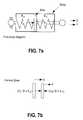
- FIG. 7 ais a free body diagram of a dynamic stabilization device in which dynamic elements are positioned between laterally-spaced pedicle screws.
- FIG. 7 bis a diagram representing the central zone of a spine and the forces associated therewith for dynamic stabilization according to the present disclosure.
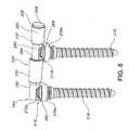
- FIG. 8is a perspective view of an exemplary dynamic stabilization device in accordance with the present disclosure.
- FIG. 9is an exploded view of the dynamic stabilization device shown in FIG. 8 .
- FIG. 10is a detailed perspective view of the distal end of a first pedicle screw for use in exemplary implementations of the present disclosure; according to exemplary embodiments of the present disclosure, the second pedicle screw is identical.
- FIG. 11is a detailed perspective view of a first pedicle screw secured to an exemplary attachment member according to the present disclosure.
- FIG. 12is a perspective view of the exemplary dynamic stabilization device shown in FIG. 8 as seen from the opposite side.
- FIG. 13is a perspective view of a dynamic stabilization device of the type depicted in FIG. 8 with a transverse torsion bar stabilizing member.
- the spinal stabilization methodis achieved by securing an internal dynamic spine stabilization device 10 between adjacent vertebrae 12 , 14 and providing mechanical assistance in the form of elastic resistance to the region of the spine to which the dynamic spine stabilization device 10 is attached.
- the elastic resistanceis applied as a function of displacement such that greater mechanical assistance is provided while the spine is in its neutral zone and lesser mechanical assistance is provided while the spine bends beyond its neutral zone.
- the “neutral zone”is understood to refer to a region of low spinal stiffness or the toe-region of the Moment-Rotation curve of the spinal segment (see FIG. 2 ). That is, the neutral zone may be considered to refer to a region of laxity around the neutral resting position of a spinal segment where there is minimal resistance to intervertebral motion. The range of the neutral zone is considered to be of major significance in determining spinal stability. Panjabi, M M. “The stabilizing system of the spine. Part II. Neutral zone and instability hypothesis.” J Spinal Disorders 1992; 5(4): 390-397.
- the inventorhas previously described the load displacement curve associated with spinal stability through the use of a “ball in a bowl” analogy.
- the shape of the bowlindicates spinal stability.
- a deeper bowlrepresents a more stable spine, while a more shallow bowl represents a less stable spine.
- the inventorpreviously hypothesized that for someone without spinal injury there is a normal neutral zone (that part of the range of motion where there is minimal resistance to intervertebral motion) with a normal range of motion, and in turn, no spinal pain.
- the bowlis not too deep nor too shallow.
- the neutral zone of the spinal columnincreases and the ball moves freely over a larger distance.
- the bowlwould be more shallow and the ball less stable, and consequently, pain results from this enlarged neutral zone.
- pedicle screws 16 , 18attach the dynamic spine stabilization device 10 to the vertebrae 12 , 14 of the spine using well-tolerated and familiar surgical procedures known to those skilled in the art.
- a pair of opposed stabilization devicesare commonly used to balance the loads applied to the spine (see FIG. 3 c ).
- the dynamic spine stabilization device 10assists the compromised (injured and/or degenerated) spine of a back pain patient, and helps her/him perform daily activities.
- the dynamic spine stabilization device 10does so by providing controlled resistance to spinal motion particularly around neutral posture in the region of neutral zone. As the spine bends forward (flexion) the stabilization device 10 is tensioned (see FIG. 3 d ) and when the spine bends backward (extension) the stabilization device 10 is compressed (see FIG. 3 e ).
- the resistance to displacement provided by the dynamic spine stabilization device 10is non-linear, being greatest in its central zone so as to correspond to the individual's neutral zone; that is, the central zone of the stabilization device 10 provides a high level of mechanical assistance in supporting the spine. As the individual moves beyond the neutral zone, the increase in resistance decreases to a more moderate level. As a result, the individual encounters greater resistance to movement (or greater incremental resistance) while moving within the neutral zone.
- the central zone of the dynamic spine stabilization device 10may be adjustable at the time of surgery to suit the neutral zone of each individual patient.
- the resistance to movement provided by the dynamic spine stabilization device 10is adjustable pre-operatively and intra-operatively. This helps to tailor the mechanical properties of the dynamic spine stabilization device 10 to suit the compromised spine of the individual patient.
- the length of the dynamic spine stabilization device 10may also be adjustable intra-operatively to suit individual patient anatomy and to achieve desired spinal posture.
- the dynamic spine stabilization device 10can be re-adjusted post-operatively with a surgical procedure to adjust its central zone to accommodate a patient's altered needs.
- ball joints 20 , 22link the dynamic spine stabilization device 10 with the pedicle screws 16 , 18 .
- the junction of the dynamic spine stabilization device 10 and pedicle screws 16 , 18is free and rotationally unconstrained. Therefore, first of all, the spine is allowed all physiological motions of bending and twisting and second, the dynamic spine stabilization device 10 and the pedicle screws 16 , 18 are protected from harmful bending and torsional forces, or moments.
- ball jointsare disclosed in accordance with a preferred/exemplary embodiment of the present disclosure, other linking structures may be utilized without departing from the spirit or scope of the present disclosure.
- the stabilization device 10sees only the spring forces. Irrespective of the large loads on the spine, such as when a person carries or lifts a heavy load, the loads coming to the stabilization device 10 are only the forces developed within the stabilization device 10 , which are the result of spinal motion and not the result of the spinal load.
- the stabilization device 10is, therefore, uniquely able to assist the spine without enduring the high loads of the spine, allowing a wide range of design options.
- the loading of the pedicle screws 16 , 18 in the present stabilization device 10is also quite different from that in prior art pedicle screw fixation devices.
- the only load the stabilizer pedicle screws 16 , 18 seeis the force from the stabilization device 10 .
- This mechanismgreatly reduces the bending moment placed onto the pedicle screws 16 , 18 as compared to prior art pedicle screw fusion systems. Due to the ball joints 20 , 22 , the bending moment within the pedicle screws 16 , 18 is essentially zero at the ball joints 20 , 22 and it increases toward the tip of the pedicle screws 16 , 18 .
- pedicle screw-bone interfacewhich often is the failure site in a typical prior art pedicle screw fixation device, is the least stressed site, and is therefore not likely to fail.
- pedicle screws 16 , 18when used in conjunction with the present invention, carry significantly less load and are placed under significantly less stress than typical pedicle screws.
- FIG. 2the Moment-Rotation curve for a healthy spine is shown in configurations with stabilization device 10 .
- This curveshows the low resistance to movement encountered in the neutral zone of a healthy spine. However, when the spine is injured, this curve changes and the spine becomes unstable, as evidenced by the expansion of the neutral zone (see FIG. 1 ).
- Profile 1is exemplary of an individual requiring great assistance in the neutral zone and the central zone of the stabilizer is therefore increased providing a high level of resistance over a great displacement
- Profile 2is exemplary of an individual where less assistance is required in the neutral zone and the central zone of the stabilizer is therefore more moderate providing increased resistance over a more limited range of displacement
- Profile 3is exemplary of situations where only slightly greater assistance is required in the neutral zone and the central zone of the stabilizer may therefore be decreased to provide increased resistance over even a smaller range of displacement.
- the mechanical assistance required and the range of the neutral zonewill vary from individual to individual.
- the basic tenet of the present inventionremains; that is, greater mechanical assistance for those individuals suffering from spinal instability is required within the individual's neutral zone.
- This assistanceis provided in the form of greater resistance to movement provided within the neutral zone of the individual and the central zone of the dynamic spine stabilizer 10 .
- the dynamic spine stabilization device 10provides mechanical assistance in accordance with the disclosed support profile. Further, the stabilization device 10 may advantageously provide for adjustability via a concentric spring design.
- the dynamic spine stabilization device 10provides assistance to the compromised spine in the form of increased resistance to movement (provided by springs in accordance with a preferred embodiment) as the spine moves from the neutral posture, in any physiological direction.
- the Force-Displacement relationship provided by the dynamic spine stabilization device 10is non-linear, with greater incremental resistance around the neutral zone of the spine and central zone of the stabilization device 10 , and decreasing incremental resistance beyond the central zone of the dynamic spine stabilization device 10 as the individual moves beyond the neutral zone (see FIG. 3 a ).
- the relationship of stabilization device 10 to forces applied during tension and compressionis further shown with reference to FIG. 3 a .
- the behavior of the stabilization device 10is non-linear.
- the Load-Displacement curvehas three zones: tension, central and compression. If K1 and K2 define the stiffness values in the tension and compression zones respectively, the present stabilizer is designed such that the high stiffness in the central zone is “K1+K2”. Depending upon the preload of the stabilization device 10 as will be discussed below in greater detail, the width of the central zone and, therefore, the region of high stiffness can be adjusted.
- the dynamic spine stabilization device 10includes a support assembly in the form of a housing 20 composed of a first housing member 22 and a second housing member 24 .
- the first housing member 22 and the second housing member 24are telescopically connected via external threads formed upon the open end 26 of the first housing member 22 and internal threads formed upon the open end 28 of the second housing member 24 .
- the housing 20is completed by screwing the first housing member 22 into the second housing member 24 .
- a piston assembly 34links the first spring 30 and the second spring 32 to first and second ball joints 36 , 38 .
- the first and second ball joints 36 , 38are in turn shaped and designed for selective attachment to pedicle screws 16 , 18 extending from the respective vertebrae 12 , 14 .
- the first ball joint 36is secured to the closed end 38 of the first housing member 20 via a threaded engagement member 40 shaped and dimensioned for coupling, with threads formed within an aperture 42 formed in the closed end 38 of the first housing member 22 . In this way, the first ball joint 36 substantially closes off the closed end 38 of the first housing member 22 .
- the length of the dynamic spine stabilization device 10may be readily adjusted by rotating the first ball joint 36 to adjust the extent of overlap between the first housing member 22 and the engagement member 40 of the first ball joint 36 .
- the closed end 44 of the second housing member 24is provided with a cap 46 having an aperture 48 formed therein.
- the aperture 48is shaped and dimensioned for the passage of a piston rod 50 from the piston assembly 34 therethrough.
- the piston assembly 34includes a piston rod 50 ; first and second springs 30 , 32 ; and retaining rods 52 .
- the piston rod 50includes a stop nut 54 and an enlarged head 56 at its first end 58 .
- the enlarged head 56is rigidly connected to the piston rod 50 and includes guide holes 60 through which the retaining rods 52 extend during operation of dynamic spine stabilization device 10 . As such, the enlarged head 56 is guided along the retaining rods 52 while the second ball joint 38 is moved toward and away from the first ball joint 36 .
- the enlarged head 56interacts with the first spring 30 to create resistance as the dynamic spine stabilization device 10 is extended and the spine is moved in flexion.
- a stop nut 54is fit over the piston rod 50 for free movement relative thereto. However, movement of the stop nut 54 toward the first ball joint 36 is prevented by the retaining rods 52 that support the stop nut 54 and prevent the stop nut 54 from moving toward the first ball joint 36 . As will be discussed below in greater detail, the stop nut 54 interacts with the second spring 32 to create resistance as the dynamic spine stabilizer 10 is compressed and the spine is moved in extension.
- the second end 62 of the piston rod 50extends from the aperture 48 at the closed end 44 of the second housing member 24 , and is attached to an engagement member 64 of the second ball joint 38 .
- the second end 62 of the piston rod 50is coupled to the engagement member 64 of the second ball joint 38 via a threaded engagement.
- a threaded engagement between the second end 62 of the piston rod 50 and the engagement member 64 of the second ball joint 38is disclosed in accordance with a preferred embodiment, although other coupling structures may be employed without departing from the spirit of the present invention.
- the first and second springs 30 , 32are held within the housing 20 .
- the first spring 30extends between the enlarged head 56 of the piston rod 50 and the cap 46 of the second housing member 24 .
- the second spring 32extends between the distal end of the engagement member 64 of the second ball joint 38 and the stop nut 54 of the piston rod 50 .
- the preloaded force applied by the first and second springs 30 , 32holds the piston rod in a static position within the housing 20 , such that the piston rod is able to move during either extension or flexion of the spine.
- the piston rod 50is pulled within the housing 24 against the force being applied by the first spring 30 .
- the enlarged head 56 of the piston rod 50is moved toward the closed end 44 of the second housing member 24 .
- This movementcauses compression of the first spring 30 , creating resistance to the movement of the spine.
- the second spring 32moves with the piston rod 50 away from second ball joint 38 .
- the height of the second spring 32is increased, reducing the distractive force, and in effect increasing the resistance of the device to movement.
- both spring 30 and spring 32resist the distraction of the device directly, either by increasing the load within the spring (i.e. first spring 30 ) or by decreasing the load assisting the motion (i.e. second spring 32 ).
- the engagement member 64 of the second ball joint 38moves toward the stop nut 54 , which is held is place by the retaining rods 52 as the piston rod 50 moves toward the first ball joint 36 .
- This movementcauses compression of the second spring 32 held between the engagement member 64 of the second ball joint 38 and the stop nut 54 , to create resistance to the movement of the dynamic spine stabilization device 10 .
- the first spring 30is supported between the cap 46 and the enlarged head 56 , and as the vertebrae move in extension within the neutral zone, the height of the second spring 30 is increased, reducing the compressive force, and in effect increasing the resistance of the device to movement.
- both spring 32 and spring 30resist the compression of the device directly, either by increasing the load within the spring (i.e. second spring 32 ) or by decreasing the load assisting the motion (i.e. first spring 30 ).
- an assistance (force) profile as shown in FIG. 2is provided by the present dynamic spine stabilizer 10 . That is, the first and second springs 30 , 32 work in conjunction to provide a large elastic force when the dynamic spine stabilization device 10 is displaced within the central zone. However, once displacement between the first ball joint 36 and the second ball joint 38 extends beyond the central zone of the stabilization device 10 and the neutral zone of the individual's spinal movement, the incremental resistance to motion is substantially reduced as the individual no longer requires the substantial assistance needed within the neutral zone. This is accomplished by setting the central zone of the device disclosed herein.
- the central zone of the force displacement curveis the area of the curve which represents when both springs are acting in the device as described above.
- the spring which is elongatingreaches its free length. Free length, as anybody skilled in the art will appreciate, is the length of a spring when no force is applied. In this mechanism the resistance to movement of the device outside the central zone (where both springs are acting to resist motion) is only reliant on the resistance of one spring: either spring 30 in flexion or spring 32 in extension.
- dynamic spine stabilization device 10may be adjusted by rotation of the first housing member 22 relative to the second housing member 24 . This movement changes the distance between the first housing member 22 and the second housing member 24 in a manner which ultimately changes the preload placed across the first and second springs 30 , 32 .
- This change in preloadalters the resistance profile of the present dynamic spine stabilization device 10 from that shown in Profile 2 of FIG. 3 a to an increase in preload (see Profile 1 of FIG. 3 a ) which enlarges the effective range in which the first and second springs 30 , 32 act in unison.
- This increased width of the central zone of the stabilization device 10correlates to higher stiffness over a larger range of motion of the spine. This effect can be reversed as evident in Profile 3 of FIG. 3 a.
- the dynamic spine stabilization device 10is attached to pedicle screws 16 , 18 extending from the vertebral section requiring support. During surgical attachment of the dynamic spine stabilization device 10 , the magnitude of the stabilizer's central zone can be adjusted for each individual patient, as judged by the surgeon and/or quantified by an instability measurement device.
- This optional adjustable feature of dynamic spine stabilization device 10is exemplified in the three explanatory profiles that have been generated in accordance with the present disclosure (see FIG. 2 ; note the width of the device central zones).
- the first and second elastic springs 30 , 32 of the dynamic spine stabilization device 10can be replaced by a different set to accommodate a wider range of spinal instabilities.
- Profile 2 bdemonstrates the force displacement curve generated with a stiffer set of springs when compared with the curve shown in Profile 2 a of FIG. 3 b.
- the length of the dynamic spine stabilization device 10is adjustable by turning the engagement member 40 of the first ball joint 36 to lengthen the stabilization device 10 in order to accommodate different patient anatomies and desired spinal posture.
- the piston rod 50may be replaced to accommodate an even wider range of anatomic variation.
- the dynamic spine stabilization device 10has been tested alone for its load-displacement relationship. When applying tension, the dynamic spine stabilization device 10 demonstrated increasing resistance up to a pre-defined displacement, followed by a reduced rate of increasing resistance until the device reached its fully elongated position. When subjected to compression, the dynamic spine stabilization device 10 demonstrated increasing resistance up to a pre-defined displacement, followed by a reduced rate of increasing resistance until the device reached its fully compressed position. Therefore, the dynamic spine stabilization device 10 exhibits a load-displacement curve that is non-linear with the greatest resistance to displacement offered around the neutral posture. This behavior helps to normalize the load-displacement curve of a compromised spine.
- the stabilization device 110may be constructed with an in-line spring arrangement.
- the housing 120is composed of first and second housing members 122 , 124 which are coupled with threads allowing for adjustability.
- a first ball joint 136extends from the first housing member 122 .
- the second housing member 124is provided with an aperture 148 through which the second end 162 of piston rod 150 extends.
- the second end 162 of the piston rod 150is attached to the second ball joint 138 .
- the second ball joint 138is screwed onto the piston rod 150 .
- the piston rod 150includes an enlarged head 156 at its first end 158 .
- the first and second springs 130 , 132are respectively secured between the enlarged head 156 and the closed ends 138 , 144 of the first and second housing members 122 , 124 . In this way, the stabilization device 110 provides resistance to both expansion and compression using the same mechanical principles described for the previous embodiment.
- Adjustment of the resistance profile in accordance with this alternate embodimentis achieved by rotating the first housing member 122 relative to the second housing member 124 . Rotation in this way alters the central zone of high resistance provided by the stabilization device 110 . As previously described one or both springs may also be exchanged to change the slope of the force-displacement curve in two or three zones respectively.
- the stabilization device 10 , 110assists a compromised spine (increased neutral zone)
- Four curvesare shown: 1. Intact, 2. Injured, 3. Stabilizer and, 4. Injured+Stabilizer. These are, respectively, the Moment-Rotation curves of the intact spine, injured spine, stabilizer alone, and stabilizer plus injured spine Notice that this curve is close to the intact curve.
- the stabilization devicewhich provides greater resistance to movement around the neutral posture, is ideally suited to compensate for the instability of the spine.
- a stabilization device 210With reference to FIGS. 8 to 13 , a stabilization device 210 according to the present disclosure is schematically depicted. This embodiment positions the first and second springs 230 , 232 on opposite sides of a pedicle screw 218 .
- the stabilization device 210includes a housing 220 having a first attachment member 260 with a first ball joint 262 extending from a first end 264 of the housing 220 and a second attachment member 266 with second ball joint 268 extending through a central portion of the stabilizer 220 .
- Each of the ball joints 262 , 268is composed of a socket 270 a , 270 b with a ball 272 a , 272 b secured therein.
- each of the pedicle screws 216 , 218includes a proximal end 274 and a distal end 276 (as the first and second pedicle screws 216 , 218 are identical, similar numerals will be used in describing them).
- the proximal end 274includes traditional threading 278 adapted for secure attachment along the spinal column of an individual.
- the distal end 276 of the pedicle screw 216 , 218is provided with a collet 278 adapted for engagement within a receiving aperture 280 a , 280 b formed within the ball 272 a , 272 b of the first and second attachment members 260 , 266 of the stabilization device 210 .
- the collet 278 at the distal end 276 of the pedicle screw 216 , 218is formed with the ability to expand and contract under the control of the medical practitioner installing the present stabilizer 210 .
- the collet 278is composed of a plurality of flexible segments 282 with a central aperture 284 therebetween.
- the flexible segments 282are adapted for movement between an expanded state used to lock the collet 278 within the receiving aperture 280 a , 280 b of the ball 272 a , 272 b and an unexpanded state wherein the collet 278 may be selectively inserted or removed from the receiving aperture 280 a , 280 b of the ball 272 a , 272 b.
- the receiving apertures 280 a , 280 b of the respective balls 272 a , 272 bare shaped and dimensioned for receiving the collet 278 of the pedicle screw 216 , 218 while it is in its unexpanded state. Retention of the collet 278 is further enhanced by the provision of a lip 286 at the distal end 276 of the collet 278 .
- the lip 286is shaped and dimensioned to grip the receiving aperture 280 a , 280 b for retaining the collet 278 therein.
- Expansion of the collet 278 of pedicle screw 216 , 218is achieved by the insertion of a set screw 288 within the central aperture 284 formed between the various segments 282 of the pedicle screw collet 278 .
- the segments 282are forced outwardly. This increases the effective diameter of the collet 278 and ultimately brings the outer surface of the collet 278 into contact with the receiving aperture 280 a , 280 b , securely locking the collet 278 , that is, the distal end 276 of the pedicle screw 216 , 218 within the receiving aperture 280 a , 280 b of the ball 272 a , 272 b.
- Access for the insertion of the set screw 288 within the central aperture 284 of the collet 278is provided by extending the receiving aperture 280 a , 280 b the entire way through the ball 272 a , 272 b .
- the collet 278is placed within the receiving aperture 280 a , 280 b of the ball 272 a , 272 b while in its unexpanded state, the set screw 288 is inserted within the central aperture 284 between the various segments 282 to cause the segments 282 to expand outwardly and lock the collet 278 within the receiving aperture 280 a , 280 b .
- the set screw 288is secured within the central aperture 284 via mating threads formed along the inner surface along of the central aperture and the outer surface of the set screw 288 .
- an alignment pin 250extends from the first attachment member 260 through a bearing aperture 290 within the second attachment member 266 .
- the alignment pin 250includes an abutment member 256 at its free end 258 .
- First and second springs 230 , 232are concentrically positioned about the alignment pin 250 .
- the first spring 230is positioned to extend between the first attachment member 260 and the second attachment member 266
- the second spring 232is positioned to extend between the second attachment member 266 and the abutment member 256 at the free end 258 of the alignment pin 250 .
- the arrangement of the alignment pin 250 , first and second attachment members 260 , 266 and first and second springs 230 , 232allows for resistive translation of the alignment pin 250 relative to the vertebrae.
- the alignment pin 250 , springs 230 , 232 and attachment members 260 , 266are arranged to create a compressive preload across the system.
- This designallows for an axial configuration which generates the desired Force-Displacement curves as shown with reference to FIG. 3 , while allowing for a much shorter distance between the first and second attachment members.
- the stabilization device disclosed abovemay also be used in the stabilization of multiple level systems. It is contemplated that stabilization on multiple levels may be achieved through the implementation of multiple alignment pins coupled via multiple spring sets and pedicle screws.
- the alignment pin 250also provides tensile force for achieving the preload utilized in conjunction with the springs 230 , 232 .
- the alignment pin 250is flexible and provides flexible guidance for the springs 230 , 232 without debris causing bearing surfaces, provides tensile for the preload, provides a low friction, straight bearing surface as it moves through the second attachment member 266 and functions at times as a straight member and at other times as a flexible guide for springs 230 , 232 .
- the alignment pin 250is cable of functioning as both a straight guide member and as a flexible guide member.
- the determination as to whether the alignment pin 250 functions as a straight guide member or a flexible guide member for the springs 230 , 232is generally based upon location of the alignment pin 250 relative to the remaining stabilization device 210 components as the spine moves. This functionality is especially important during flexion.
- the alignment pin 250has a uniform cross sectional shape capable of performing as both a straight guide member and a flexed guide member.
- the stabilization device 210may be used in conjunction with a torsion bar 292 connecting the stabilization device 210 to adjacent stabilizers as shown in FIG. 3 c .
- the torsion bar 292is connected to the attachment members 260 , 266 of adjacent stabilization devices with conventional connection structures.
- the use of the torsion bar 292increases stability in axial rotation or lateral bending.
- the torsion bar 292generally has a uniform cross section for purposes where uniform torsion is required.
- the torsion bar 292may have an asymmetric cross section so as to provide for flexibility of stiffness in two planes.
- the asymmetric cross sectional torsion bar 292will affect the system stiffness in lateral bending and axial rotation independently.
- the torsion bar 292may be utilized to tune the systems stabilization in all three planes.
- a link-devicemay be provided for joining the left- and right-stabilizer units to help provide additional stability in axial rotation and lateral bending.
- This link-devicewould be a supplement to the dynamic spine stabilization device and would be applied as needed on an individual patient basis.
- a spinal stability measurement devicemay be utilized. The measurement device would be used to quantify the stability of each spinal level at the time of surgery. This device would attach intra-operatively to a pair of adjacent spinal components at compromised and uncompromised spinal levels to measure the stability of each level. The stability measurements of the adjacent uninjured levels relative to the injured level(s) can be used to determine the appropriate adjustment of the device.
- the stability measurements of the injured spinal level(s)can be used to adjust the device by referring to a tabulated database of normal uninjured spinal stabilities.
- the devicewill be simple and robust, so that the surgeon is provided with the information in the simplest possible manner under operative conditions.
- spring(s)to be used in accordance with the present disclosure to achieve the desired force profile curve is governed by the basic physical laws governing the force produced by springs.
- the force profile described above and shown in FIG. 3 ais achieved through the unique design of the present stabilizer.
- the stabilization devicefunctions both in compression and tension, even through the two springs within the stabilizer are both of compression type.
- the higher stiffness (K 1 +K 2 ) provided by the stabilization device in the central zoneis due to the presence of a preload. Both springs are made to work together, when the preload is present.
- the stabilization deviceis either tensioned or compressed, the force increases in one spring and decreases in the other.
- the decreasing forcereaches the zero value, the spring corresponding to this force no longer functions, thus decreasing the stabilization device function
- an engineering analysisincluding the diagrams shown in FIGS. 7 a and 7 b , is presented below (the analysis specifically relates to the embodiment disclosed in FIG. 5 , although those skilled in the art will appreciate the way in which it applies to all embodiments disclosed in accordance with the present invention).
Landscapes
- Health & Medical Sciences (AREA)
- Orthopedic Medicine & Surgery (AREA)
- Life Sciences & Earth Sciences (AREA)
- Neurology (AREA)
- Surgery (AREA)
- Heart & Thoracic Surgery (AREA)
- Engineering & Computer Science (AREA)
- Biomedical Technology (AREA)
- Nuclear Medicine, Radiotherapy & Molecular Imaging (AREA)
- Medical Informatics (AREA)
- Molecular Biology (AREA)
- Animal Behavior & Ethology (AREA)
- General Health & Medical Sciences (AREA)
- Public Health (AREA)
- Veterinary Medicine (AREA)
- Surgical Instruments (AREA)
- Prostheses (AREA)
Abstract
Description
- F0is the preload within the stabilization device, introduced by shortening the body length of the housing as discussed above.
- K1and K2are stiffness coefficients of the compression springs, active during stabilization device tensioning and compression, respectively.
- F and D are respectively the force and displacement of the disc of the stabilization device with respect to the body of the stabilizer.
- The sum of forces on the disc must equal zero. Therefore,
F+(F0−D×K2)−(F0+D×K1)=0, and
F=D×(K1+K2). - With regard to the central zone (CZ) width (see
FIG. 3 a):- On Tension side CZTis:
CZT=F0/K2. - On Compression side CZcis:
CZc=F0/K1.
- On Tension side CZTis:
Claims (34)
Priority Applications (4)
| Application Number | Priority Date | Filing Date | Title |
|---|---|---|---|
| US11/159,471US7931675B2 (en) | 2004-06-23 | 2005-06-23 | Dynamic stabilization device including overhanging stabilizing member |
| US13/089,878US8500781B2 (en) | 2004-06-23 | 2011-04-19 | Method for stabilizing a spine |
| US13/409,605US9005252B2 (en) | 2004-06-23 | 2012-03-01 | Method for stabilizing a spine |
| US14/683,270US9681893B2 (en) | 2004-06-23 | 2015-04-10 | Method for stabilizing a spine |
Applications Claiming Priority (2)
| Application Number | Priority Date | Filing Date | Title |
|---|---|---|---|
| US58171604P | 2004-06-23 | 2004-06-23 | |
| US11/159,471US7931675B2 (en) | 2004-06-23 | 2005-06-23 | Dynamic stabilization device including overhanging stabilizing member |
Related Child Applications (1)
| Application Number | Title | Priority Date | Filing Date |
|---|---|---|---|
| US13/089,878DivisionUS8500781B2 (en) | 2004-06-23 | 2011-04-19 | Method for stabilizing a spine |
Publications (2)
| Publication Number | Publication Date |
|---|---|
| US20050288670A1 US20050288670A1 (en) | 2005-12-29 |
| US7931675B2true US7931675B2 (en) | 2011-04-26 |
Family
ID=34982242
Family Applications (5)
| Application Number | Title | Priority Date | Filing Date |
|---|---|---|---|
| US11/159,471Active2029-06-25US7931675B2 (en) | 2004-06-23 | 2005-06-23 | Dynamic stabilization device including overhanging stabilizing member |
| US11/159,469AbandonedUS20060015100A1 (en) | 2004-06-23 | 2005-06-23 | Spinal stabilization devices coupled by torsional member |
| US13/089,878Expired - Fee RelatedUS8500781B2 (en) | 2004-06-23 | 2011-04-19 | Method for stabilizing a spine |
| US13/409,605Expired - Fee RelatedUS9005252B2 (en) | 2004-06-23 | 2012-03-01 | Method for stabilizing a spine |
| US14/683,270Expired - Fee RelatedUS9681893B2 (en) | 2004-06-23 | 2015-04-10 | Method for stabilizing a spine |
Family Applications After (4)
| Application Number | Title | Priority Date | Filing Date |
|---|---|---|---|
| US11/159,469AbandonedUS20060015100A1 (en) | 2004-06-23 | 2005-06-23 | Spinal stabilization devices coupled by torsional member |
| US13/089,878Expired - Fee RelatedUS8500781B2 (en) | 2004-06-23 | 2011-04-19 | Method for stabilizing a spine |
| US13/409,605Expired - Fee RelatedUS9005252B2 (en) | 2004-06-23 | 2012-03-01 | Method for stabilizing a spine |
| US14/683,270Expired - Fee RelatedUS9681893B2 (en) | 2004-06-23 | 2015-04-10 | Method for stabilizing a spine |
Country Status (5)
| Country | Link |
|---|---|
| US (5) | US7931675B2 (en) |
| CN (1) | CN101090675A (en) |
| IL (1) | IL180114A0 (en) |
| WO (1) | WO2006002359A2 (en) |
| ZA (1) | ZA200700451B (en) |
Cited By (31)
| Publication number | Priority date | Publication date | Assignee | Title |
|---|---|---|---|---|
| US20090105828A1 (en)* | 2007-10-22 | 2009-04-23 | Gimbel Jonathan A | Posterior stabilization system with isolated, dual dampener systems |
| US20090105757A1 (en)* | 2007-10-22 | 2009-04-23 | Gimbel Jonathan A | Posterior stabilization systems with shared, dual dampener systems |
| US20100131010A1 (en)* | 2007-07-24 | 2010-05-27 | Henry Graf | Extra discal intervertebral stabilization element for arthrodesis |
| US20100185247A1 (en)* | 2008-09-09 | 2010-07-22 | Richelsoph Marc E | Polyaxial screw assembly |
| US20100318130A1 (en)* | 2007-12-15 | 2010-12-16 | Parlato Brian D | Flexible rod assembly for spinal fixation |
| US20110196428A1 (en)* | 2004-06-23 | 2011-08-11 | Rachiotek Llc | Method for stabilizing a spine |
| US8118871B2 (en) | 2003-08-05 | 2012-02-21 | Flexuspine, Inc. | Expandable articulating intervertebral implant |
| US8118869B2 (en) | 2006-03-08 | 2012-02-21 | Flexuspine, Inc. | Dynamic interbody device |
| US8157844B2 (en) | 2007-10-22 | 2012-04-17 | Flexuspine, Inc. | Dampener system for a posterior stabilization system with a variable length elongated member |
| US8182514B2 (en) | 2007-10-22 | 2012-05-22 | Flexuspine, Inc. | Dampener system for a posterior stabilization system with a fixed length elongated member |
| US8187330B2 (en) | 2007-10-22 | 2012-05-29 | Flexuspine, Inc. | Dampener system for a posterior stabilization system with a variable length elongated member |
| US8267965B2 (en) | 2007-10-22 | 2012-09-18 | Flexuspine, Inc. | Spinal stabilization systems with dynamic interbody devices |
| US20120253404A1 (en)* | 2003-05-02 | 2012-10-04 | Rachiotek, Llc | Method for stabilizing a spinal segment |
| US20120271353A1 (en)* | 2010-08-16 | 2012-10-25 | Mark Barry | System and method for aligning vertebrae in the amelioration of aberrant spinal column deviation conditions in patients requiring the accomodation of spinal column growth or elongation |
| US8317836B2 (en) | 2007-06-05 | 2012-11-27 | Spartek Medical, Inc. | Bone anchor for receiving a rod for stabilization and motion preservation spinal implantation system and method |
| US8377098B2 (en) | 2007-01-19 | 2013-02-19 | Flexuspine, Inc. | Artificial functional spinal unit system and method for use |
| US8394127B2 (en) | 2009-12-02 | 2013-03-12 | Spartek Medical, Inc. | Low profile spinal prosthesis incorporating a bone anchor having a deflectable post and a compound spinal rod |
| US8430916B1 (en) | 2012-02-07 | 2013-04-30 | Spartek Medical, Inc. | Spinal rod connectors, methods of use, and spinal prosthesis incorporating spinal rod connectors |
| US8603168B2 (en) | 2003-08-05 | 2013-12-10 | Flexuspine, Inc. | Artificial functional spinal unit system and method for use |
| US20140094852A1 (en)* | 2003-09-24 | 2014-04-03 | DePuy Synthes Products, LLC | Spinal Stabilization Device |
| US8940051B2 (en) | 2011-03-25 | 2015-01-27 | Flexuspine, Inc. | Interbody device insertion systems and methods |
| US20150201970A1 (en)* | 2012-07-11 | 2015-07-23 | Joshua Aferzon | Dynamic spinal stabilization rod |
| US20150313643A1 (en)* | 2003-05-02 | 2015-11-05 | Yale University | Dynamic Spine Stablizer |
| US9456851B2 (en) | 2007-10-23 | 2016-10-04 | Intelligent Implant Systems, Llc | Spinal implant |
| US9492288B2 (en) | 2013-02-20 | 2016-11-15 | Flexuspine, Inc. | Expandable fusion device for positioning between adjacent vertebral bodies |
| US9517144B2 (en) | 2014-04-24 | 2016-12-13 | Exactech, Inc. | Limited profile intervertebral implant with incorporated fastening mechanism |
| US9526531B2 (en) | 2013-10-07 | 2016-12-27 | Intelligent Implant Systems, Llc | Polyaxial plate rod system and surgical procedure |
| US9526627B2 (en) | 2011-11-17 | 2016-12-27 | Exactech, Inc. | Expandable interbody device system and method |
| US9668788B2 (en) | 2004-12-30 | 2017-06-06 | Mark A. Barry | System and method for aligning vertebrae in the amelioration of aberrant spinal column deviation conditions |
| US10398565B2 (en) | 2014-04-24 | 2019-09-03 | Choice Spine, Llc | Limited profile intervertebral implant with incorporated fastening and locking mechanism |
| US11583318B2 (en) | 2018-12-21 | 2023-02-21 | Paradigm Spine, Llc | Modular spine stabilization system and associated instruments |
Families Citing this family (178)
| Publication number | Priority date | Publication date | Assignee | Title |
|---|---|---|---|---|
| FR2812185B1 (en) | 2000-07-25 | 2003-02-28 | Spine Next Sa | SEMI-RIGID CONNECTION PIECE FOR RACHIS STABILIZATION |
| US7833250B2 (en) | 2004-11-10 | 2010-11-16 | Jackson Roger P | Polyaxial bone screw with helically wound capture connection |
| US8292926B2 (en) | 2005-09-30 | 2012-10-23 | Jackson Roger P | Dynamic stabilization connecting member with elastic core and outer sleeve |
| US8353932B2 (en) | 2005-09-30 | 2013-01-15 | Jackson Roger P | Polyaxial bone anchor assembly with one-piece closure, pressure insert and plastic elongate member |
| US10258382B2 (en) | 2007-01-18 | 2019-04-16 | Roger P. Jackson | Rod-cord dynamic connection assemblies with slidable bone anchor attachment members along the cord |
| US7862587B2 (en) | 2004-02-27 | 2011-01-04 | Jackson Roger P | Dynamic stabilization assemblies, tool set and method |
| US10729469B2 (en) | 2006-01-09 | 2020-08-04 | Roger P. Jackson | Flexible spinal stabilization assembly with spacer having off-axis core member |
| IL162363A0 (en)* | 2001-12-07 | 2005-11-20 | Mathys Medizinaltechnik Ag | Damping element |
| AU2003265597A1 (en)* | 2002-08-23 | 2004-03-11 | Paul C. Mcafee | Metal-backed uhmpe rod sleeve system preserving spinal motion |
| US8876868B2 (en) | 2002-09-06 | 2014-11-04 | Roger P. Jackson | Helical guide and advancement flange with radially loaded lip |
| WO2006052796A2 (en) | 2004-11-10 | 2006-05-18 | Jackson Roger P | Helical guide and advancement flange with break-off extensions |
| US8540753B2 (en) | 2003-04-09 | 2013-09-24 | Roger P. Jackson | Polyaxial bone screw with uploaded threaded shank and method of assembly and use |
| US7621918B2 (en) | 2004-11-23 | 2009-11-24 | Jackson Roger P | Spinal fixation tool set and method |
| US7377923B2 (en) | 2003-05-22 | 2008-05-27 | Alphatec Spine, Inc. | Variable angle spinal screw assembly |
| US8926670B2 (en) | 2003-06-18 | 2015-01-06 | Roger P. Jackson | Polyaxial bone screw assembly |
| US8366753B2 (en) | 2003-06-18 | 2013-02-05 | Jackson Roger P | Polyaxial bone screw assembly with fixed retaining structure |
| US7967850B2 (en) | 2003-06-18 | 2011-06-28 | Jackson Roger P | Polyaxial bone anchor with helical capture connection, insert and dual locking assembly |
| US7776067B2 (en) | 2005-05-27 | 2010-08-17 | Jackson Roger P | Polyaxial bone screw with shank articulation pressure insert and method |
| US7766915B2 (en) | 2004-02-27 | 2010-08-03 | Jackson Roger P | Dynamic fixation assemblies with inner core and outer coil-like member |
| US8092500B2 (en) | 2007-05-01 | 2012-01-10 | Jackson Roger P | Dynamic stabilization connecting member with floating core, compression spacer and over-mold |
| US7909869B2 (en)* | 2003-08-05 | 2011-03-22 | Flexuspine, Inc. | Artificial spinal unit assemblies |
| US7763052B2 (en) | 2003-12-05 | 2010-07-27 | N Spine, Inc. | Method and apparatus for flexible fixation of a spine |
| US7137985B2 (en)* | 2003-09-24 | 2006-11-21 | N Spine, Inc. | Marking and guidance method and system for flexible fixation of a spine |
| US20050203513A1 (en)* | 2003-09-24 | 2005-09-15 | Tae-Ahn Jahng | Spinal stabilization device |
| US7815665B2 (en)* | 2003-09-24 | 2010-10-19 | N Spine, Inc. | Adjustable spinal stabilization system |
| BR0318485A (en)* | 2003-09-29 | 2006-09-12 | Synthes Gmbh | dynamic damping element for two bones |
| US7179261B2 (en) | 2003-12-16 | 2007-02-20 | Depuy Spine, Inc. | Percutaneous access devices and bone anchor assemblies |
| US7527638B2 (en) | 2003-12-16 | 2009-05-05 | Depuy Spine, Inc. | Methods and devices for minimally invasive spinal fixation element placement |
| US11419642B2 (en) | 2003-12-16 | 2022-08-23 | Medos International Sarl | Percutaneous access devices and bone anchor assemblies |
| US8029548B2 (en) | 2008-05-05 | 2011-10-04 | Warsaw Orthopedic, Inc. | Flexible spinal stabilization element and system |
| JP2007525274A (en) | 2004-02-27 | 2007-09-06 | ロジャー・ピー・ジャクソン | Orthopedic implant rod reduction instrument set and method |
| US11241261B2 (en) | 2005-09-30 | 2022-02-08 | Roger P Jackson | Apparatus and method for soft spinal stabilization using a tensionable cord and releasable end structure |
| US7160300B2 (en) | 2004-02-27 | 2007-01-09 | Jackson Roger P | Orthopedic implant rod reduction tool set and method |
| US8152810B2 (en) | 2004-11-23 | 2012-04-10 | Jackson Roger P | Spinal fixation tool set and method |
| CA2574277A1 (en)* | 2004-08-09 | 2006-02-23 | Innovative Spinal Technologies, Inc. | System and method for dynamic skeletal stabilization |
| US7854752B2 (en) | 2004-08-09 | 2010-12-21 | Theken Spine, Llc | System and method for dynamic skeletal stabilization |
| DE202004020396U1 (en) | 2004-08-12 | 2005-07-07 | Columbus Trading-Partners Pos und Brendel GbR (vertretungsberechtigte Gesellschafter Karin Brendel, 95503 Hummeltal und Bohumila Pos, 95445 Bayreuth) | Child seat for motor vehicles |
| US7651502B2 (en) | 2004-09-24 | 2010-01-26 | Jackson Roger P | Spinal fixation tool set and method for rod reduction and fastener insertion |
| US7896906B2 (en)* | 2004-12-30 | 2011-03-01 | Depuy Spine, Inc. | Artificial facet joint |
| DE102004048938B4 (en)* | 2004-10-07 | 2015-04-02 | Synthes Gmbh | Device for the dynamic stabilization of vertebral bodies |
| US8226690B2 (en)* | 2005-07-22 | 2012-07-24 | The Board Of Trustees Of The Leland Stanford Junior University | Systems and methods for stabilization of bone structures |
| US8267969B2 (en) | 2004-10-20 | 2012-09-18 | Exactech, Inc. | Screw systems and methods for use in stabilization of bone structures |
| US8162985B2 (en) | 2004-10-20 | 2012-04-24 | The Board Of Trustees Of The Leland Stanford Junior University | Systems and methods for posterior dynamic stabilization of the spine |
| US8025680B2 (en) | 2004-10-20 | 2011-09-27 | Exactech, Inc. | Systems and methods for posterior dynamic stabilization of the spine |
| US7935134B2 (en) | 2004-10-20 | 2011-05-03 | Exactech, Inc. | Systems and methods for stabilization of bone structures |
| US20070239159A1 (en)* | 2005-07-22 | 2007-10-11 | Vertiflex, Inc. | Systems and methods for stabilization of bone structures |
| US8926672B2 (en) | 2004-11-10 | 2015-01-06 | Roger P. Jackson | Splay control closure for open bone anchor |
| US9980753B2 (en) | 2009-06-15 | 2018-05-29 | Roger P Jackson | pivotal anchor with snap-in-place insert having rotation blocking extensions |
| US8444681B2 (en) | 2009-06-15 | 2013-05-21 | Roger P. Jackson | Polyaxial bone anchor with pop-on shank, friction fit retainer and winged insert |
| US9168069B2 (en) | 2009-06-15 | 2015-10-27 | Roger P. Jackson | Polyaxial bone anchor with pop-on shank and winged insert with lower skirt for engaging a friction fit retainer |
| WO2006057837A1 (en) | 2004-11-23 | 2006-06-01 | Jackson Roger P | Spinal fixation tool attachment structure |
| US9216041B2 (en) | 2009-06-15 | 2015-12-22 | Roger P. Jackson | Spinal connecting members with tensioned cords and rigid sleeves for engaging compression inserts |
| WO2006058221A2 (en) | 2004-11-24 | 2006-06-01 | Abdou Samy M | Devices and methods for inter-vertebral orthopedic device placement |
| US20060229613A1 (en)* | 2004-12-31 | 2006-10-12 | Timm Jens P | Sheath assembly for spinal stabilization device |
| US7901437B2 (en) | 2007-01-26 | 2011-03-08 | Jackson Roger P | Dynamic stabilization member with molded connection |
| WO2006090380A2 (en)* | 2005-02-22 | 2006-08-31 | Orthogon Technologies 2003 Ltd. | Device and method for vertebral column distraction and oscillation |
| US10076361B2 (en) | 2005-02-22 | 2018-09-18 | Roger P. Jackson | Polyaxial bone screw with spherical capture, compression and alignment and retention structures |
| US7604654B2 (en) | 2005-02-22 | 2009-10-20 | Stryker Spine | Apparatus and method for dynamic vertebral stabilization |
| US8523865B2 (en) | 2005-07-22 | 2013-09-03 | Exactech, Inc. | Tissue splitter |
| US8105368B2 (en) | 2005-09-30 | 2012-01-31 | Jackson Roger P | Dynamic stabilization connecting member with slitted core and outer sleeve |
| US7857833B2 (en)* | 2005-10-06 | 2010-12-28 | Abdou M Samy | Devices and methods for inter-vertebral orthopedic device placement |
| US8137385B2 (en) | 2005-10-31 | 2012-03-20 | Stryker Spine | System and method for dynamic vertebral stabilization |
| US8034078B2 (en) | 2008-05-30 | 2011-10-11 | Globus Medical, Inc. | System and method for replacement of spinal motion segment |
| US7704271B2 (en) | 2005-12-19 | 2010-04-27 | Abdou M Samy | Devices and methods for inter-vertebral orthopedic device placement |
| US7578849B2 (en) | 2006-01-27 | 2009-08-25 | Warsaw Orthopedic, Inc. | Intervertebral implants and methods of use |
| US7682376B2 (en) | 2006-01-27 | 2010-03-23 | Warsaw Orthopedic, Inc. | Interspinous devices and methods of use |
| US7815663B2 (en) | 2006-01-27 | 2010-10-19 | Warsaw Orthopedic, Inc. | Vertebral rods and methods of use |
| US7776075B2 (en)* | 2006-01-31 | 2010-08-17 | Warsaw Orthopedic, Inc. | Expandable spinal rods and methods of use |
| US8025681B2 (en) | 2006-03-29 | 2011-09-27 | Theken Spine, Llc | Dynamic motion spinal stabilization system |
| US7942905B2 (en)* | 2006-04-20 | 2011-05-17 | Warsaw Orthopedic, Inc. | Vertebral stabilizer |
| US20070288012A1 (en)* | 2006-04-21 | 2007-12-13 | Dennis Colleran | Dynamic motion spinal stabilization system and device |
| US8361129B2 (en) | 2006-04-28 | 2013-01-29 | Depuy Spine, Inc. | Large diameter bone anchor assembly |
| US20070281305A1 (en)* | 2006-06-05 | 2007-12-06 | Sean Wuxiong Cao | Detection of lymph node metastasis from gastric carcinoma |
| US20070288009A1 (en)* | 2006-06-08 | 2007-12-13 | Steven Brown | Dynamic spinal stabilization device |
| US8858600B2 (en)* | 2006-06-08 | 2014-10-14 | Spinadyne, Inc. | Dynamic spinal stabilization device |
| US20080058808A1 (en) | 2006-06-14 | 2008-03-06 | Spartek Medical, Inc. | Implant system and method to treat degenerative disorders of the spine |
| US7666211B2 (en)* | 2006-12-28 | 2010-02-23 | Mi4Spine, Llc | Vertebral disc annular fibrosis tensioning and lengthening device |
| WO2008003047A2 (en) | 2006-06-28 | 2008-01-03 | Synthes (U.S.A.) | Dynamic fixation system |
| US8308770B2 (en)* | 2006-09-22 | 2012-11-13 | Depuy Spine, Inc. | Dynamic stabilization system |
| US8096996B2 (en) | 2007-03-20 | 2012-01-17 | Exactech, Inc. | Rod reducer |
| CA2670988C (en) | 2006-12-08 | 2014-03-25 | Roger P. Jackson | Tool system for dynamic spinal implants |
| US8475498B2 (en) | 2007-01-18 | 2013-07-02 | Roger P. Jackson | Dynamic stabilization connecting member with cord connection |
| US8366745B2 (en) | 2007-05-01 | 2013-02-05 | Jackson Roger P | Dynamic stabilization assembly having pre-compressed spacers with differential displacements |
| US8109975B2 (en)* | 2007-01-30 | 2012-02-07 | Warsaw Orthopedic, Inc. | Collar bore configuration for dynamic spinal stabilization assembly |
| US8029547B2 (en)* | 2007-01-30 | 2011-10-04 | Warsaw Orthopedic, Inc. | Dynamic spinal stabilization assembly with sliding collars |
| US8034081B2 (en) | 2007-02-06 | 2011-10-11 | CollabComl, LLC | Interspinous dynamic stabilization implant and method of implanting |
| US9414861B2 (en) | 2007-02-09 | 2016-08-16 | Transcendental Spine, Llc | Dynamic stabilization device |
| US8012177B2 (en) | 2007-02-12 | 2011-09-06 | Jackson Roger P | Dynamic stabilization assembly with frusto-conical connection |
| US20080255615A1 (en)* | 2007-03-27 | 2008-10-16 | Warsaw Orthopedic, Inc. | Treatments for Correcting Spinal Deformities |
| WO2008134703A2 (en) | 2007-04-30 | 2008-11-06 | Globus Medical, Inc. | Flexible spine stabilization system |
| US8979904B2 (en) | 2007-05-01 | 2015-03-17 | Roger P Jackson | Connecting member with tensioned cord, low profile rigid sleeve and spacer with torsion control |
| US10383660B2 (en) | 2007-05-01 | 2019-08-20 | Roger P. Jackson | Soft stabilization assemblies with pretensioned cords |
| CA2690038C (en) | 2007-05-31 | 2012-11-27 | Roger P. Jackson | Dynamic stabilization connecting member with pre-tensioned solid core |
| US8021396B2 (en) | 2007-06-05 | 2011-09-20 | Spartek Medical, Inc. | Configurable dynamic spinal rod and method for dynamic stabilization of the spine |
| US8114134B2 (en) | 2007-06-05 | 2012-02-14 | Spartek Medical, Inc. | Spinal prosthesis having a three bar linkage for motion preservation and dynamic stabilization of the spine |
| US8083772B2 (en) | 2007-06-05 | 2011-12-27 | Spartek Medical, Inc. | Dynamic spinal rod assembly and method for dynamic stabilization of the spine |
| US8109970B2 (en) | 2007-06-05 | 2012-02-07 | Spartek Medical, Inc. | Deflection rod system with a deflection contouring shield for a spine implant and method |
| US8052722B2 (en) | 2007-06-05 | 2011-11-08 | Spartek Medical, Inc. | Dual deflection rod system for a dynamic stabilization and motion preservation spinal implantation system and method |
| US8092501B2 (en) | 2007-06-05 | 2012-01-10 | Spartek Medical, Inc. | Dynamic spinal rod and method for dynamic stabilization of the spine |
| US8048123B2 (en) | 2007-06-05 | 2011-11-01 | Spartek Medical, Inc. | Spine implant with a deflection rod system and connecting linkages and method |
| US8048115B2 (en) | 2007-06-05 | 2011-11-01 | Spartek Medical, Inc. | Surgical tool and method for implantation of a dynamic bone anchor |
| EP2178451A2 (en)* | 2007-08-07 | 2010-04-28 | Synthes GmbH | Dynamic cable system |
| US8080038B2 (en)* | 2007-08-17 | 2011-12-20 | Jmea Corporation | Dynamic stabilization device for spine |
| US8911477B2 (en) | 2007-10-23 | 2014-12-16 | Roger P. Jackson | Dynamic stabilization member with end plate support and cable core extension |
| US9232968B2 (en) | 2007-12-19 | 2016-01-12 | DePuy Synthes Products, Inc. | Polymeric pedicle rods and methods of manufacturing |
| US8337536B2 (en) | 2008-02-26 | 2012-12-25 | Spartek Medical, Inc. | Load-sharing bone anchor having a deflectable post with a compliant ring and method for stabilization of the spine |
| US8007518B2 (en) | 2008-02-26 | 2011-08-30 | Spartek Medical, Inc. | Load-sharing component having a deflectable post and method for dynamic stabilization of the spine |
| US8083775B2 (en) | 2008-02-26 | 2011-12-27 | Spartek Medical, Inc. | Load-sharing bone anchor having a natural center of rotation and method for dynamic stabilization of the spine |
| US8267979B2 (en) | 2008-02-26 | 2012-09-18 | Spartek Medical, Inc. | Load-sharing bone anchor having a deflectable post and axial spring and method for dynamic stabilization of the spine |
| US8048125B2 (en) | 2008-02-26 | 2011-11-01 | Spartek Medical, Inc. | Versatile offset polyaxial connector and method for dynamic stabilization of the spine |
| US8057517B2 (en) | 2008-02-26 | 2011-11-15 | Spartek Medical, Inc. | Load-sharing component having a deflectable post and centering spring and method for dynamic stabilization of the spine |
| FR2927791B1 (en)* | 2008-02-26 | 2011-02-18 | Clariance | ARTICULAR PROSTHESIS POSTERIEURE LUMBAR WITH ROTULE |
| US8211155B2 (en) | 2008-02-26 | 2012-07-03 | Spartek Medical, Inc. | Load-sharing bone anchor having a durable compliant member and method for dynamic stabilization of the spine |
| US8097024B2 (en) | 2008-02-26 | 2012-01-17 | Spartek Medical, Inc. | Load-sharing bone anchor having a deflectable post and method for stabilization of the spine |
| US8333792B2 (en) | 2008-02-26 | 2012-12-18 | Spartek Medical, Inc. | Load-sharing bone anchor having a deflectable post and method for dynamic stabilization of the spine |
| US9060813B1 (en) | 2008-02-29 | 2015-06-23 | Nuvasive, Inc. | Surgical fixation system and related methods |
| US8043340B1 (en)* | 2008-06-09 | 2011-10-25 | Melvin Law | Dynamic spinal stabilization system |
| AU2010260521C1 (en) | 2008-08-01 | 2013-08-01 | Roger P. Jackson | Longitudinal connecting member with sleeved tensioned cords |
| ES2394670T3 (en)* | 2008-10-08 | 2013-02-04 | Biedermann Technologies Gmbh & Co. Kg | Elongated implant device and vertebral stabilization device |
| WO2010078029A1 (en) | 2008-12-17 | 2010-07-08 | Synthes Usa, Llc | Posterior spine dynamic stabilizer |
| US8641734B2 (en) | 2009-02-13 | 2014-02-04 | DePuy Synthes Products, LLC | Dual spring posterior dynamic stabilization device with elongation limiting elastomers |
| US8118840B2 (en) | 2009-02-27 | 2012-02-21 | Warsaw Orthopedic, Inc. | Vertebral rod and related method of manufacture |
| US8372116B2 (en)* | 2009-04-13 | 2013-02-12 | Warsaw Orthopedic, Inc. | Systems and devices for dynamic stabilization of the spine |
| US8292927B2 (en)* | 2009-04-24 | 2012-10-23 | Warsaw Orthopedic, Inc. | Flexible articulating spinal rod |
| US8202301B2 (en)* | 2009-04-24 | 2012-06-19 | Warsaw Orthopedic, Inc. | Dynamic spinal rod and implantation method |
| US20110040331A1 (en)* | 2009-05-20 | 2011-02-17 | Jose Fernandez | Posterior stabilizer |
| US8998959B2 (en) | 2009-06-15 | 2015-04-07 | Roger P Jackson | Polyaxial bone anchors with pop-on shank, fully constrained friction fit retainer and lock and release insert |
| US11229457B2 (en) | 2009-06-15 | 2022-01-25 | Roger P. Jackson | Pivotal bone anchor assembly with insert tool deployment |
| US9668771B2 (en) | 2009-06-15 | 2017-06-06 | Roger P Jackson | Soft stabilization assemblies with off-set connector |
| CN103826560A (en) | 2009-06-15 | 2014-05-28 | 罗杰.P.杰克逊 | Polyaxial Bone Anchor with Socket Stem and Winged Inserts with Friction Fit Compression Collars |
| US9320543B2 (en) | 2009-06-25 | 2016-04-26 | DePuy Synthes Products, Inc. | Posterior dynamic stabilization device having a mobile anchor |
| US9011494B2 (en) | 2009-09-24 | 2015-04-21 | Warsaw Orthopedic, Inc. | Composite vertebral rod system and methods of use |
| EP2485654B1 (en) | 2009-10-05 | 2021-05-05 | Jackson P. Roger | Polyaxial bone anchor with non-pivotable retainer and pop-on shank, some with friction fit |
| US8361123B2 (en) | 2009-10-16 | 2013-01-29 | Depuy Spine, Inc. | Bone anchor assemblies and methods of manufacturing and use thereof |
| US8764806B2 (en) | 2009-12-07 | 2014-07-01 | Samy Abdou | Devices and methods for minimally invasive spinal stabilization and instrumentation |
| US9445844B2 (en) | 2010-03-24 | 2016-09-20 | DePuy Synthes Products, Inc. | Composite material posterior dynamic stabilization spring rod |
| US9198696B1 (en) | 2010-05-27 | 2015-12-01 | Nuvasive, Inc. | Cross-connector and related methods |
| US20110307015A1 (en) | 2010-06-10 | 2011-12-15 | Spartek Medical, Inc. | Adaptive spinal rod and methods for stabilization of the spine |
| AU2011299558A1 (en) | 2010-09-08 | 2013-05-02 | Roger P. Jackson | Dynamic stabilization members with elastic and inelastic sections |
| AU2011324058A1 (en) | 2010-11-02 | 2013-06-20 | Roger P. Jackson | Polyaxial bone anchor with pop-on shank and pivotable retainer |
| US9247964B1 (en) | 2011-03-01 | 2016-02-02 | Nuasive, Inc. | Spinal Cross-connector |
| US9387013B1 (en) | 2011-03-01 | 2016-07-12 | Nuvasive, Inc. | Posterior cervical fixation system |
| JP5865479B2 (en) | 2011-03-24 | 2016-02-17 | ロジャー・ピー・ジャクソン | Multiaxial bone anchor with compound joint and pop-mounted shank |
| US9808290B2 (en)* | 2011-07-06 | 2017-11-07 | Moximed, Inc. | Transcutaneous joint unloading device |
| FR2978343B1 (en)* | 2011-07-25 | 2013-08-23 | Medicrea International | ANCHORING BODY FOR VERTEBRAL OSTEOSYNTHESIS EQUIPMENT |
| US8845728B1 (en) | 2011-09-23 | 2014-09-30 | Samy Abdou | Spinal fixation devices and methods of use |
| US20130226240A1 (en) | 2012-02-22 | 2013-08-29 | Samy Abdou | Spinous process fixation devices and methods of use |
| CN102579121B (en)* | 2012-03-09 | 2014-02-26 | 中国人民解放军第二军医大学 | A kind of atlas pedicle screw |
| US9198767B2 (en) | 2012-08-28 | 2015-12-01 | Samy Abdou | Devices and methods for spinal stabilization and instrumentation |
| CN102836001A (en)* | 2012-09-14 | 2012-12-26 | 苏州艾迪尔医疗器械有限公司 | Universal coaptation nail for minimally invasive surgery |
| US9320617B2 (en) | 2012-10-22 | 2016-04-26 | Cogent Spine, LLC | Devices and methods for spinal stabilization and instrumentation |
| US8911478B2 (en) | 2012-11-21 | 2014-12-16 | Roger P. Jackson | Splay control closure for open bone anchor |
| US10058354B2 (en) | 2013-01-28 | 2018-08-28 | Roger P. Jackson | Pivotal bone anchor assembly with frictional shank head seating surfaces |
| US8852239B2 (en) | 2013-02-15 | 2014-10-07 | Roger P Jackson | Sagittal angle screw with integral shank and receiver |
| WO2014150786A1 (en)* | 2013-03-15 | 2014-09-25 | Moximed, Inc. | Implantation approach and instrumentality for an energy absorbing system |
| US9566092B2 (en) | 2013-10-29 | 2017-02-14 | Roger P. Jackson | Cervical bone anchor with collet retainer and outer locking sleeve |
| US9717533B2 (en) | 2013-12-12 | 2017-08-01 | Roger P. Jackson | Bone anchor closure pivot-splay control flange form guide and advancement structure |
| US9451993B2 (en) | 2014-01-09 | 2016-09-27 | Roger P. Jackson | Bi-radial pop-on cervical bone anchor |
| CN103767780A (en)* | 2014-01-20 | 2014-05-07 | 倪文飞 | Inner fixer for quantized bracing of bone vertebral fracture |
| US9597119B2 (en) | 2014-06-04 | 2017-03-21 | Roger P. Jackson | Polyaxial bone anchor with polymer sleeve |
| US10064658B2 (en) | 2014-06-04 | 2018-09-04 | Roger P. Jackson | Polyaxial bone anchor with insert guides |
| FR3037784B1 (en)* | 2015-06-29 | 2017-12-15 | Gexfix Sa | DEVICE FOR EXTERNALLY DYNAMIC OSTEOSYNTHESIS FASTENING |
| CN105105837B (en)* | 2015-07-16 | 2017-12-22 | 沈阳东亚医疗研究所有限公司 | Bone-fracture fixation steel plate system |
| US10857003B1 (en) | 2015-10-14 | 2020-12-08 | Samy Abdou | Devices and methods for vertebral stabilization |
| CN105250017B (en)* | 2015-11-30 | 2018-03-06 | 昆明医科大学第二附属医院 | A kind of orthopedic rod connector that multidirectional offer angle compensation is provided |
| CN105596072A (en)* | 2016-03-08 | 2016-05-25 | 中国人民解放军第二军医大学 | Vertebral malformation correcting instrument |
| CN106236231A (en)* | 2016-07-04 | 2016-12-21 | 威海市妇幼保健院 | A kind of spinal column dynamic connection rod |
| US10973648B1 (en) | 2016-10-25 | 2021-04-13 | Samy Abdou | Devices and methods for vertebral bone realignment |
| US10744000B1 (en) | 2016-10-25 | 2020-08-18 | Samy Abdou | Devices and methods for vertebral bone realignment |
| CN108606859B (en)* | 2016-12-12 | 2024-04-02 | 创生医疗器械(中国)有限公司 | Locked lumbar fusion device |
| CN109288572B (en)* | 2017-07-24 | 2024-04-09 | 北京纳通医学科技研究院有限公司 | Screw plug quick-assembling device |
| CN107550619B (en)* | 2017-10-24 | 2020-09-25 | 南阳市中心医院 | Leg fracture resetting device for orthopedics department |
| US11179248B2 (en) | 2018-10-02 | 2021-11-23 | Samy Abdou | Devices and methods for spinal implantation |
| ES2988747T3 (en)* | 2019-07-02 | 2024-11-21 | Neo Medical Sa | System to prevent lateral tension on bone structures resulting from off-axis forces caused by the screwdriver and screw extender |
| CN111603346B (en)* | 2020-05-28 | 2022-02-08 | 上海长征医院 | Spine surgery device based on mixed reality technology |
| US11699577B2 (en)* | 2021-05-25 | 2023-07-11 | Applied Materials, Inc. | Treatment for high-temperature cleans |
| US11331125B1 (en) | 2021-10-07 | 2022-05-17 | Ortho Inventions, Llc | Low profile rod-to-rod coupler |
| CN114848241A (en)* | 2022-04-27 | 2022-08-05 | 中国人民解放军空军军医大学 | Single-side and double-side spine lumbar shock-absorbing articular process prosthesis |
Citations (66)
| Publication number | Priority date | Publication date | Assignee | Title |
|---|---|---|---|---|
| US2733596A (en) | 1956-02-07 | Measurement of dynamic modulus of | ||
| US4328960A (en) | 1978-02-16 | 1982-05-11 | Fichtel & Sachs Ag | Fluid damping unit featuring combined fluidic and spring damping characteristics |
| US4352514A (en) | 1977-12-21 | 1982-10-05 | Firster Corporation Limited | Shock absorbing device |
| US4558852A (en) | 1982-03-11 | 1985-12-17 | Sig Schweizerische Industrie-Gesellschaft | Vibration damper with linearly reciprocating mass |
| US4743260A (en) | 1985-06-10 | 1988-05-10 | Burton Charles V | Method for a flexible stabilization system for a vertebral column |
| US4759769A (en) | 1987-02-12 | 1988-07-26 | Health & Research Services Inc. | Artificial spinal disc |
| US5034011A (en) | 1990-08-09 | 1991-07-23 | Advanced Spine Fixation Systems Incorporated | Segmental instrumentation of the posterior spine |
| EP0516567A1 (en) | 1991-05-30 | 1992-12-02 | Société dite: "PSI" | Shock-absorbing device for intervertebral stabilisation |
| US5174551A (en) | 1990-06-20 | 1992-12-29 | Stabilus Gmbh | Cylinder piston device |
| US5180393A (en) | 1990-09-21 | 1993-01-19 | Polyclinique De Bourgogne & Les Hortensiad | Artificial ligament for the spine |
| FR2681520A1 (en) | 1991-09-24 | 1993-03-26 | Graf Henry | DEVICE FOR MEASURING AMPLITUDES OF TWO VERTEBRATES IN THREE ORTHOGONAL PLANS. |
| FR2692468A1 (en) | 1992-06-19 | 1993-12-24 | Grae Henry | Spreading and spacing instrument for surgery on vertebrae - has series of tubular shafts, each attached to implant screwed into vertebra, for positioning flexible plastics sheet spreading muscle tissue |
| EP0576379A1 (en) | 1992-06-25 | 1993-12-29 | Psi | Use of dampers with improved damping at the end of stroke in a device for intervertebral stabilisation |
| FR2694182A1 (en) | 1992-07-31 | 1994-02-04 | Psi | Fastening for interpedicular vertebral prosthesis components - comprises bone-implanted shafts, with spherical heads engaged over upper portions for cooperation with prosthesis-attached rings |
| EP0611554A1 (en) | 1993-02-17 | 1994-08-24 | Psi | Extradiscal intravertebral prosthesis for the control of intervertebral distance variations by means of a double damper |
| FR2701651A1 (en) | 1993-02-17 | 1994-08-26 | Psi | Double shock-absorber for intervertebral stabilisation |
| US5415661A (en) | 1993-03-24 | 1995-05-16 | University Of Miami | Implantable spinal assist device |
| CA2135838A1 (en) | 1993-11-18 | 1995-05-19 | Henry Graf | Extra-discal intervertebral prosthesis |
| US5423816A (en) | 1993-07-29 | 1995-06-13 | Lin; Chih I. | Intervertebral locking device |
| US5501684A (en) | 1992-06-25 | 1996-03-26 | Synthes (U.S.A.) | Osteosynthetic fixation device |
| US5505118A (en) | 1991-09-16 | 1996-04-09 | Forsvarets Forskningsinstitutt | Gun barrel vibration damper |
| US5653680A (en) | 1995-08-10 | 1997-08-05 | Cruz; Mark K. | Active wrist brace |
| US5672175A (en) | 1993-08-27 | 1997-09-30 | Martin; Jean Raymond | Dynamic implanted spinal orthosis and operative procedure for fitting |
| CA2213058A1 (en) | 1996-08-01 | 1998-02-01 | Henry Graf | Device for binding together and mechanically assisting the vertebra |
| JPH10277070A (en) | 1997-04-09 | 1998-10-20 | Shigeo Sano | Artificial intervertebral joint |
| USRE36221E (en) | 1989-02-03 | 1999-06-01 | Breard; Francis Henri | Flexible inter-vertebral stabilizer as well as process and apparatus for determining or verifying its tension before installation on the spinal column |
| FR2772594A1 (en) | 1997-12-19 | 1999-06-25 | Henry Graf | Partial posterior intervertebral disc prosthesis |
| FR2794362A1 (en) | 1999-06-02 | 2000-12-08 | Henry Graf | INTERVERTEBRAL IMPLANT AND INSTALLATION ASSEMBLY OF SUCH AN IMPLANT |
| US6162223A (en) | 1999-04-09 | 2000-12-19 | Smith & Nephew, Inc. | Dynamic wrist fixation apparatus for early joint motion in distal radius fractures |
| US6176860B1 (en) | 1995-07-24 | 2001-01-23 | Hadasit Medical Research Services & Development Company, Ltd. | Orthopaedic fixator |
| FR2799949A1 (en) | 1999-10-22 | 2001-04-27 | Abder Benazza | Spinal osteosynthesis apparatus has lengthwise supports in form of single or double spiral springs to allow for movement |
| US6241730B1 (en) | 1997-11-26 | 2001-06-05 | Scient'x (Societe A Responsabilite Limitee) | Intervertebral link device capable of axial and angular displacement |
| WO2001039678A1 (en) | 1999-12-01 | 2001-06-07 | Henry Graf | Intervertebral stabilising device |
| FR2801782A1 (en) | 1999-12-01 | 2001-06-08 | Henry Graf | Intervertebral stabiliser comprises implant between adjacent vertebrae and movement damper to rear of spine |
| WO2001045576A1 (en) | 1999-12-20 | 2001-06-28 | Synthes Ag Chur | Device for the stabilisation of two adjacent verterbral bodies of the spine |
| FR2803188A1 (en) | 1999-12-29 | 2001-07-06 | Henry Graf | DEVICE AND INTERVERTEBRAL STABILIZATION ASSEMBLY |
| US6267764B1 (en) | 1996-11-15 | 2001-07-31 | Stryker France S.A. | Osteosynthesis system with elastic deformation for spinal column |
| US6293949B1 (en) | 2000-03-01 | 2001-09-25 | Sdgi Holdings, Inc. | Superelastic spinal stabilization system and method |
| FR2809304A1 (en) | 2000-05-24 | 2001-11-30 | Henry Graf | Intervertebral stabiliser comprises implant between adjacent vertebrae and movement damper to rear of spine |
| WO2002000124A1 (en) | 2000-06-30 | 2002-01-03 | Sdgi Holdings, Inc. | Intervertebral linking device |
| FR2810873A1 (en) | 2000-06-30 | 2002-01-04 | Henry Graf | Intervertebral coupling for two or more vertebrae has intermediate element between fixed and mobile components to allow movement |
| FR2812535A1 (en) | 2000-08-01 | 2002-02-08 | Henry Graf | Intervertebral coupling for two or more vertebrae has intermediate element between fixed and mobile components to allow movement |
| US6375681B1 (en) | 1998-06-23 | 2002-04-23 | Ebi, L.P. | Vertebral body replacement |
| US6402750B1 (en) | 2000-04-04 | 2002-06-11 | Spinlabs, Llc | Devices and methods for the treatment of spinal disorders |
| US6440169B1 (en) | 1998-02-10 | 2002-08-27 | Dimso | Interspinous stabilizer to be fixed to spinous processes of two vertebrae |
| US20020151978A1 (en) | 1996-07-22 | 2002-10-17 | Fred Zacouto | Skeletal implant |
| WO2002102259A2 (en) | 2001-06-16 | 2002-12-27 | Dilip Kumar Sengupta | An assembly for the stabilisation of vertebral bodies of the spine |
| US6508818B2 (en) | 1998-08-21 | 2003-01-21 | Synthes (U.S.A.) | Bone anchoring assembly with a snap-in ballhead |
| US6554831B1 (en) | 2000-09-01 | 2003-04-29 | Hopital Sainte-Justine | Mobile dynamic system for treating spinal disorder |
| GB2382304A (en) | 2001-10-10 | 2003-05-28 | Dilip Kumar Sengupta | An assembly for soft stabilisation of vertebral bodies of the spine |
| US20030171749A1 (en) | 2000-07-25 | 2003-09-11 | Regis Le Couedic | Semirigid linking piece for stabilizing the spine |
| US6645207B2 (en) | 2000-05-08 | 2003-11-11 | Robert A. Dixon | Method and apparatus for dynamized spinal stabilization |
| US20030220643A1 (en) | 2002-05-24 | 2003-11-27 | Ferree Bret A. | Devices to prevent spinal extension |
| US20030220642A1 (en) | 2002-05-21 | 2003-11-27 | Stefan Freudiger | Elastic stabilization system for vertebral columns |
| US20040049189A1 (en) | 2000-07-25 | 2004-03-11 | Regis Le Couedic | Flexible linking piece for stabilising the spine |
| US20040049190A1 (en) | 2002-08-09 | 2004-03-11 | Biedermann Motech Gmbh | Dynamic stabilization device for bones, in particular for vertebrae |
| US20040082954A1 (en) | 2000-06-23 | 2004-04-29 | Teitelbaum George P. | Formable orthopedic fixation system with cross linking |
| US20040143264A1 (en) | 2002-08-23 | 2004-07-22 | Mcafee Paul C. | Metal-backed UHMWPE rod sleeve system preserving spinal motion |
| US20040147928A1 (en) | 2002-10-30 | 2004-07-29 | Landry Michael E. | Spinal stabilization system using flexible members |
| US20040167523A1 (en) | 2000-12-08 | 2004-08-26 | Jackson Roger P. | Closure for rod receiving orthopedic implant having a pair of spaced apertures for removal |
| US20040267260A1 (en) | 2003-06-16 | 2004-12-30 | Thomas Mack | Implant for correction and stabilization of the spinal column |
| US20050203519A1 (en) | 2004-03-09 | 2005-09-15 | Jurgen Harms | Rod-like element for application in spinal or trauma surgery, and stabilization device with such a rod-like element |
| US20060247635A1 (en) | 2003-08-05 | 2006-11-02 | Gordon Charles R | Dynamic posterior stabilization systems and methods of use |
| US20060264937A1 (en) | 2005-05-04 | 2006-11-23 | White Patrick M | Mobile spine stabilization device |
| US20070016190A1 (en) | 2005-07-14 | 2007-01-18 | Medical Device Concepts Llc | Dynamic spinal stabilization system |
| US7326210B2 (en) | 2003-09-24 | 2008-02-05 | N Spine, Inc | Spinal stabilization device |
Family Cites Families (53)
| Publication number | Priority date | Publication date | Assignee | Title |
|---|---|---|---|---|
| US2382304A (en)* | 1941-03-24 | 1945-08-14 | Foltz Carl | Knife and method of manufacture thereof |
| US2812535A (en)* | 1954-09-13 | 1957-11-12 | Gen Motors Corp | Hinge hold-open |
| DE1048358B (en)* | 1955-08-12 | 1959-01-08 | ||
| US3581608A (en) | 1969-11-05 | 1971-06-01 | Gardner Denver Co | Cutting and stripping apparatus for insulated conductor wire |
| US4738251A (en)* | 1987-02-20 | 1988-04-19 | Codespi, Corporation | Correcting device for spine pathology |
| US4875471A (en)* | 1987-02-20 | 1989-10-24 | Codespi Corporation | Device for correcting deformities of the spine |
| CH674709A5 (en)* | 1988-04-27 | 1990-07-13 | Sulzer Ag | |
| JPH0620466B2 (en)* | 1989-03-31 | 1994-03-23 | 有限会社田中医科器械製作所 | Spinal column correction device |
| US5080512A (en) | 1990-02-21 | 1992-01-14 | Datacard Corporation | Apparatus and method for printing including slide mechanism |
| US5092893A (en)* | 1990-09-04 | 1992-03-03 | Smith Thomas E | Human orthopedic vertebra implant |
| US5176679A (en)* | 1991-09-23 | 1993-01-05 | Lin Chih I | Vertebral locking and retrieving system |
| AU659912B2 (en)* | 1992-03-10 | 1995-06-01 | Bristol-Myers Squibb Company | Perpendicular rod connector for spinal fixation device |
| ZA937672B (en)* | 1992-10-22 | 1994-05-16 | Danek Medical Inc | Spinal rod transverse connector for supporting vertebral fixation elements |
| DE4303770C1 (en)* | 1993-02-09 | 1994-05-26 | Plus Endoprothetik Ag Rotkreuz | Stiffening and correction system for spinal vertebrae - comprises screw-ended holders with connecting rod supporting clamped distance pieces. |
| US5601554A (en)* | 1993-03-04 | 1997-02-11 | Advanced Spine Fixation Systems, Inc. | Branch connector for spinal fixation systems |
| US5531745A (en)* | 1993-03-11 | 1996-07-02 | Danek Medical, Inc. | System for stabilizing the spine and reducing spondylolisthesis |
| US5437669A (en)* | 1993-08-12 | 1995-08-01 | Amei Technologies Inc. | Spinal fixation systems with bifurcated connectors |
| WO1995010238A1 (en)* | 1993-10-08 | 1995-04-20 | Chaim Rogozinski | Spinal treatment apparatus and method including multi-directional attachment member |
| US5403316A (en)* | 1993-12-02 | 1995-04-04 | Danek Medical, Inc. | Triangular construct for spinal fixation |
| SE9402130D0 (en)* | 1994-06-17 | 1994-06-17 | Sven Olerud | Device and method for plate fixation of legs |
| US5681311A (en)* | 1994-09-15 | 1997-10-28 | Smith & Nephew, Inc. | Osteosynthesis apparatus |
| US5630816A (en)* | 1995-05-01 | 1997-05-20 | Kambin; Parviz | Double barrel spinal fixation system and method |
| US5947966A (en)* | 1995-06-06 | 1999-09-07 | Sdgi Holdings, Inc. | Device for linking adjacent rods in spinal instrumentation |
| US5713900A (en)* | 1996-05-31 | 1998-02-03 | Acromed Corporation | Apparatus for retaining bone portions in a desired spatial relationship |
| DE19705228A1 (en)* | 1997-02-12 | 1998-08-13 | Bosch Gmbh Robert | Electrical machine, preferably a three-phase generator with a rectifier unit |
| FR2761590B1 (en)* | 1997-04-04 | 1999-08-20 | Stryker France Sa | DEVICE FOR OSTEOSYNTHESIS OF THE RACHIS WITH ATTACHMENT OF DEAXED INTERVERTEBRAL ROD |
| DE19803628A1 (en)* | 1997-07-09 | 1999-01-14 | Holger K Dr Essiger | Device for the regeneration, repair and modeling of human and animal bones, especially in the dental jaw area |
| US6454769B2 (en)* | 1997-08-04 | 2002-09-24 | Spinal Concepts, Inc. | System and method for stabilizing the human spine with a bone plate |
| US6030389A (en)* | 1997-08-04 | 2000-02-29 | Spinal Concepts, Inc. | System and method for stabilizing the human spine with a bone plate |
| US5980523A (en)* | 1998-01-08 | 1999-11-09 | Jackson; Roger | Transverse connectors for spinal rods |
| US6355038B1 (en)* | 1998-09-25 | 2002-03-12 | Perumala Corporation | Multi-axis internal spinal fixation |
| US6235033B1 (en)* | 2000-04-19 | 2001-05-22 | Synthes (Usa) | Bone fixation assembly |
| US6641583B2 (en)* | 2001-03-29 | 2003-11-04 | Endius Incorporated | Apparatus for retaining bone portions in a desired spatial relationship |
| JP4755781B2 (en)* | 2001-08-01 | 2011-08-24 | 昭和医科工業株式会社 | Jointing member for osteosynthesis |
| US6623485B2 (en)* | 2001-10-17 | 2003-09-23 | Hammill Manufacturing Company | Split ring bone screw for a spinal fixation system |
| US7335201B2 (en)* | 2003-09-26 | 2008-02-26 | Zimmer Spine, Inc. | Polyaxial bone screw with torqueless fastening |
| US7101398B2 (en)* | 2002-12-31 | 2006-09-05 | Depuy Acromed, Inc. | Prosthetic facet joint ligament |
| EP1596738A4 (en)* | 2003-02-25 | 2010-01-20 | Stephen Ritland | Adjustable rod and connector device and method of use |
| US7289562B2 (en)* | 2003-08-01 | 2007-10-30 | Polycom, Inc. | Adaptive filter to improve H-264 video quality |
| US7794476B2 (en)* | 2003-08-08 | 2010-09-14 | Warsaw Orthopedic, Inc. | Implants formed of shape memory polymeric material for spinal fixation |
| US7591837B2 (en)* | 2003-10-28 | 2009-09-22 | Pyramid Spine, Llc | Facet triangle spinal fixation device and method of use |
| US7862586B2 (en)* | 2003-11-25 | 2011-01-04 | Life Spine, Inc. | Spinal stabilization systems |
| DE102004010844A1 (en)* | 2004-03-05 | 2005-10-06 | Biedermann Motech Gmbh | Stabilizing device for the dynamic stabilization of vertebrae or bones and rod-shaped element for such a stabilization device |
| US7717939B2 (en)* | 2004-03-31 | 2010-05-18 | Depuy Spine, Inc. | Rod attachment for head to head cross connector |
| US7645294B2 (en)* | 2004-03-31 | 2010-01-12 | Depuy Spine, Inc. | Head-to-head connector spinal fixation system |
| US7931675B2 (en)* | 2004-06-23 | 2011-04-26 | Yale University | Dynamic stabilization device including overhanging stabilizing member |
| US7854752B2 (en)* | 2004-08-09 | 2010-12-21 | Theken Spine, Llc | System and method for dynamic skeletal stabilization |
| US20060084976A1 (en)* | 2004-09-30 | 2006-04-20 | Depuy Spine, Inc. | Posterior stabilization systems and methods |
| US7896906B2 (en)* | 2004-12-30 | 2011-03-01 | Depuy Spine, Inc. | Artificial facet joint |
| US7294129B2 (en)* | 2005-02-18 | 2007-11-13 | Ebi, L.P. | Spinal fixation device and associated method |
| US7951169B2 (en)* | 2005-06-10 | 2011-05-31 | Depuy Spine, Inc. | Posterior dynamic stabilization cross connectors |
| US8118869B2 (en)* | 2006-03-08 | 2012-02-21 | Flexuspine, Inc. | Dynamic interbody device |
| WO2008134703A2 (en)* | 2007-04-30 | 2008-11-06 | Globus Medical, Inc. | Flexible spine stabilization system |
- 2005
- 2005-06-23USUS11/159,471patent/US7931675B2/enactiveActive
- 2005-06-23WOPCT/US2005/022432patent/WO2006002359A2/enactiveApplication Filing
- 2005-06-23CNCNA2005800267844Apatent/CN101090675A/enactivePending
- 2005-06-23USUS11/159,469patent/US20060015100A1/ennot_activeAbandoned
- 2005-06-23ZAZA200700451Apatent/ZA200700451B/enunknown
- 2006
- 2006-12-17ILIL180114Apatent/IL180114A0/enunknown
- 2011
- 2011-04-19USUS13/089,878patent/US8500781B2/ennot_activeExpired - Fee Related
- 2012
- 2012-03-01USUS13/409,605patent/US9005252B2/ennot_activeExpired - Fee Related
- 2015
- 2015-04-10USUS14/683,270patent/US9681893B2/ennot_activeExpired - Fee Related
Patent Citations (92)
| Publication number | Priority date | Publication date | Assignee | Title |
|---|---|---|---|---|
| US2733596A (en) | 1956-02-07 | Measurement of dynamic modulus of | ||
| US4352514A (en) | 1977-12-21 | 1982-10-05 | Firster Corporation Limited | Shock absorbing device |
| US4328960A (en) | 1978-02-16 | 1982-05-11 | Fichtel & Sachs Ag | Fluid damping unit featuring combined fluidic and spring damping characteristics |
| US4558852A (en) | 1982-03-11 | 1985-12-17 | Sig Schweizerische Industrie-Gesellschaft | Vibration damper with linearly reciprocating mass |
| US4650167A (en) | 1982-03-11 | 1987-03-17 | Sig Schweizerische Industrie-Gesellschaft | Vibration damper |
| US4743260A (en) | 1985-06-10 | 1988-05-10 | Burton Charles V | Method for a flexible stabilization system for a vertebral column |
| US4759769A (en) | 1987-02-12 | 1988-07-26 | Health & Research Services Inc. | Artificial spinal disc |
| USRE36221E (en) | 1989-02-03 | 1999-06-01 | Breard; Francis Henri | Flexible inter-vertebral stabilizer as well as process and apparatus for determining or verifying its tension before installation on the spinal column |
| US5174551A (en) | 1990-06-20 | 1992-12-29 | Stabilus Gmbh | Cylinder piston device |
| US5034011A (en) | 1990-08-09 | 1991-07-23 | Advanced Spine Fixation Systems Incorporated | Segmental instrumentation of the posterior spine |
| US5180393A (en) | 1990-09-21 | 1993-01-19 | Polyclinique De Bourgogne & Les Hortensiad | Artificial ligament for the spine |
| EP0516567A1 (en) | 1991-05-30 | 1992-12-02 | Société dite: "PSI" | Shock-absorbing device for intervertebral stabilisation |
| US5540688A (en) | 1991-05-30 | 1996-07-30 | Societe "Psi" | Intervertebral stabilization device incorporating dampers |
| FR2676911A1 (en) | 1991-05-30 | 1992-12-04 | Psi Ste Civile Particuliere | INTERVERTEBRAL STABILIZATION DEVICE WITH SHOCK ABSORBERS. |
| US5505118A (en) | 1991-09-16 | 1996-04-09 | Forsvarets Forskningsinstitutt | Gun barrel vibration damper |
| FR2681520A1 (en) | 1991-09-24 | 1993-03-26 | Graf Henry | DEVICE FOR MEASURING AMPLITUDES OF TWO VERTEBRATES IN THREE ORTHOGONAL PLANS. |
| EP0534874A1 (en) | 1991-09-24 | 1993-03-31 | Henry Graf | Device for measuring the amplitude of movement between two vertebra in three orthogonal planes |
| US5291901A (en) | 1991-09-24 | 1994-03-08 | Henry Graf | Device for measuring angular movement of vertebrae |
| US5329933A (en) | 1991-09-24 | 1994-07-19 | Henry Graf | Device for measuring the angle of movement of two vertebrae |
| FR2692468A1 (en) | 1992-06-19 | 1993-12-24 | Grae Henry | Spreading and spacing instrument for surgery on vertebrae - has series of tubular shafts, each attached to implant screwed into vertebra, for positioning flexible plastics sheet spreading muscle tissue |
| US5375823A (en) | 1992-06-25 | 1994-12-27 | Societe Psi | Application of an improved damper to an intervertebral stabilization device |
| JPH07289562A (en) | 1992-06-25 | 1995-11-07 | Psi Soc | Damper |
| US5501684A (en) | 1992-06-25 | 1996-03-26 | Synthes (U.S.A.) | Osteosynthetic fixation device |
| EP0576379A1 (en) | 1992-06-25 | 1993-12-29 | Psi | Use of dampers with improved damping at the end of stroke in a device for intervertebral stabilisation |
| FR2694182A1 (en) | 1992-07-31 | 1994-02-04 | Psi | Fastening for interpedicular vertebral prosthesis components - comprises bone-implanted shafts, with spherical heads engaged over upper portions for cooperation with prosthesis-attached rings |
| FR2701650A1 (en) | 1993-02-17 | 1994-08-26 | Psi | Double shock absorber for intervertebral stabilization. |
| FR2701651A1 (en) | 1993-02-17 | 1994-08-26 | Psi | Double shock-absorber for intervertebral stabilisation |
| JPH06285100A (en) | 1993-02-17 | 1994-10-11 | Psi | Relief device as prosthesis for stabilizing interbody |
| EP0611554A1 (en) | 1993-02-17 | 1994-08-24 | Psi | Extradiscal intravertebral prosthesis for the control of intervertebral distance variations by means of a double damper |
| US5480401A (en) | 1993-02-17 | 1996-01-02 | Psi | Extra-discal inter-vertebral prosthesis for controlling the variations of the inter-vertebral distance by means of a double damper |
| US5415661A (en) | 1993-03-24 | 1995-05-16 | University Of Miami | Implantable spinal assist device |
| US5423816A (en) | 1993-07-29 | 1995-06-13 | Lin; Chih I. | Intervertebral locking device |
| US5672175A (en) | 1993-08-27 | 1997-09-30 | Martin; Jean Raymond | Dynamic implanted spinal orthosis and operative procedure for fitting |
| CA2135838A1 (en) | 1993-11-18 | 1995-05-19 | Henry Graf | Extra-discal intervertebral prosthesis |
| US5562737A (en) | 1993-11-18 | 1996-10-08 | Henry Graf | Extra-discal intervertebral prosthesis |
| US6176860B1 (en) | 1995-07-24 | 2001-01-23 | Hadasit Medical Research Services & Development Company, Ltd. | Orthopaedic fixator |
| US5653680A (en) | 1995-08-10 | 1997-08-05 | Cruz; Mark K. | Active wrist brace |
| US20020151978A1 (en) | 1996-07-22 | 2002-10-17 | Fred Zacouto | Skeletal implant |
| FR2751864A1 (en) | 1996-08-01 | 1998-02-06 | Graf Henry | DEVICE FOR MECHANICALLY CONNECTING AND ASSISTING VERTEBRES BETWEEN THEM |
| JPH1071157A (en) | 1996-08-01 | 1998-03-17 | Henry Graf | Device for mechanically connecting and assisting spinal bones to each other and its installation method |
| CA2213058A1 (en) | 1996-08-01 | 1998-02-01 | Henry Graf | Device for binding together and mechanically assisting the vertebra |
| US5961516A (en) | 1996-08-01 | 1999-10-05 | Graf; Henry | Device for mechanically connecting and assisting vertebrae with respect to one another |
| EP0821917A1 (en) | 1996-08-01 | 1998-02-04 | Henry Graf | Connecting and mechanical supporting device for vertebrae |
| US6267764B1 (en) | 1996-11-15 | 2001-07-31 | Stryker France S.A. | Osteosynthesis system with elastic deformation for spinal column |
| JPH10277070A (en) | 1997-04-09 | 1998-10-20 | Shigeo Sano | Artificial intervertebral joint |
| US6241730B1 (en) | 1997-11-26 | 2001-06-05 | Scient'x (Societe A Responsabilite Limitee) | Intervertebral link device capable of axial and angular displacement |
| WO1999032054A1 (en) | 1997-12-19 | 1999-07-01 | Sofamor Danek Holdings, Inc. | Partial discal prosthesis |
| EP1039855A1 (en) | 1997-12-19 | 2000-10-04 | Sofamor Danek Properties Inc | Partial discal prosthesis |
| FR2775891A1 (en) | 1997-12-19 | 1999-09-17 | Henry Graf | Partial posterior intervertebral disc prosthesis |
| FR2772594A1 (en) | 1997-12-19 | 1999-06-25 | Henry Graf | Partial posterior intervertebral disc prosthesis |
| US6419706B1 (en) | 1997-12-19 | 2002-07-16 | Sofamor S.N.C. | Partial disc prosthesis |
| AU744241B2 (en) | 1997-12-19 | 2002-02-21 | Warsaw Orthopedic, Inc. | Partial discal prosthesis |
| US6440169B1 (en) | 1998-02-10 | 2002-08-27 | Dimso | Interspinous stabilizer to be fixed to spinous processes of two vertebrae |
| US6375681B1 (en) | 1998-06-23 | 2002-04-23 | Ebi, L.P. | Vertebral body replacement |
| US6508818B2 (en) | 1998-08-21 | 2003-01-21 | Synthes (U.S.A.) | Bone anchoring assembly with a snap-in ballhead |
| US6162223A (en) | 1999-04-09 | 2000-12-19 | Smith & Nephew, Inc. | Dynamic wrist fixation apparatus for early joint motion in distal radius fractures |
| FR2794362A1 (en) | 1999-06-02 | 2000-12-08 | Henry Graf | INTERVERTEBRAL IMPLANT AND INSTALLATION ASSEMBLY OF SUCH AN IMPLANT |
| FR2799949A1 (en) | 1999-10-22 | 2001-04-27 | Abder Benazza | Spinal osteosynthesis apparatus has lengthwise supports in form of single or double spiral springs to allow for movement |
| US20030055427A1 (en) | 1999-12-01 | 2003-03-20 | Henry Graf | Intervertebral stabilising device |
| WO2001039678A1 (en) | 1999-12-01 | 2001-06-07 | Henry Graf | Intervertebral stabilising device |
| FR2801782A1 (en) | 1999-12-01 | 2001-06-08 | Henry Graf | Intervertebral stabiliser comprises implant between adjacent vertebrae and movement damper to rear of spine |
| WO2001045576A1 (en) | 1999-12-20 | 2001-06-28 | Synthes Ag Chur | Device for the stabilisation of two adjacent verterbral bodies of the spine |
| WO2001049192A1 (en) | 1999-12-29 | 2001-07-12 | Henry Graf | Device and assembly for intervertebral stabilisation |
| FR2803188A1 (en) | 1999-12-29 | 2001-07-06 | Henry Graf | DEVICE AND INTERVERTEBRAL STABILIZATION ASSEMBLY |
| US6293949B1 (en) | 2000-03-01 | 2001-09-25 | Sdgi Holdings, Inc. | Superelastic spinal stabilization system and method |
| US6761719B2 (en) | 2000-03-01 | 2004-07-13 | Sdgi Holdings, Inc. | Superelastic spinal stabilization system and method |
| US6402750B1 (en) | 2000-04-04 | 2002-06-11 | Spinlabs, Llc | Devices and methods for the treatment of spinal disorders |
| US20020095154A1 (en) | 2000-04-04 | 2002-07-18 | Atkinson Robert E. | Devices and methods for the treatment of spinal disorders |
| US6835205B2 (en) | 2000-04-04 | 2004-12-28 | Spinalabs, Llc | Devices and methods for the treatment of spinal disorders |
| US6645207B2 (en) | 2000-05-08 | 2003-11-11 | Robert A. Dixon | Method and apparatus for dynamized spinal stabilization |
| FR2809304A1 (en) | 2000-05-24 | 2001-11-30 | Henry Graf | Intervertebral stabiliser comprises implant between adjacent vertebrae and movement damper to rear of spine |
| US20040082954A1 (en) | 2000-06-23 | 2004-04-29 | Teitelbaum George P. | Formable orthopedic fixation system with cross linking |
| WO2002000124A1 (en) | 2000-06-30 | 2002-01-03 | Sdgi Holdings, Inc. | Intervertebral linking device |
| FR2810873A1 (en) | 2000-06-30 | 2002-01-04 | Henry Graf | Intervertebral coupling for two or more vertebrae has intermediate element between fixed and mobile components to allow movement |
| US20030171749A1 (en) | 2000-07-25 | 2003-09-11 | Regis Le Couedic | Semirigid linking piece for stabilizing the spine |
| US20040049189A1 (en) | 2000-07-25 | 2004-03-11 | Regis Le Couedic | Flexible linking piece for stabilising the spine |
| FR2812535A1 (en) | 2000-08-01 | 2002-02-08 | Henry Graf | Intervertebral coupling for two or more vertebrae has intermediate element between fixed and mobile components to allow movement |
| US6554831B1 (en) | 2000-09-01 | 2003-04-29 | Hopital Sainte-Justine | Mobile dynamic system for treating spinal disorder |
| US20040167523A1 (en) | 2000-12-08 | 2004-08-26 | Jackson Roger P. | Closure for rod receiving orthopedic implant having a pair of spaced apertures for removal |
| WO2002102259A2 (en) | 2001-06-16 | 2002-12-27 | Dilip Kumar Sengupta | An assembly for the stabilisation of vertebral bodies of the spine |
| GB2382304A (en) | 2001-10-10 | 2003-05-28 | Dilip Kumar Sengupta | An assembly for soft stabilisation of vertebral bodies of the spine |
| US20030220642A1 (en) | 2002-05-21 | 2003-11-27 | Stefan Freudiger | Elastic stabilization system for vertebral columns |
| US20030220643A1 (en) | 2002-05-24 | 2003-11-27 | Ferree Bret A. | Devices to prevent spinal extension |
| US20040049190A1 (en) | 2002-08-09 | 2004-03-11 | Biedermann Motech Gmbh | Dynamic stabilization device for bones, in particular for vertebrae |
| US20040143264A1 (en) | 2002-08-23 | 2004-07-22 | Mcafee Paul C. | Metal-backed UHMWPE rod sleeve system preserving spinal motion |
| US20040147928A1 (en) | 2002-10-30 | 2004-07-29 | Landry Michael E. | Spinal stabilization system using flexible members |
| US20040267260A1 (en) | 2003-06-16 | 2004-12-30 | Thomas Mack | Implant for correction and stabilization of the spinal column |
| US20060247635A1 (en) | 2003-08-05 | 2006-11-02 | Gordon Charles R | Dynamic posterior stabilization systems and methods of use |
| US7326210B2 (en) | 2003-09-24 | 2008-02-05 | N Spine, Inc | Spinal stabilization device |
| US20050203519A1 (en) | 2004-03-09 | 2005-09-15 | Jurgen Harms | Rod-like element for application in spinal or trauma surgery, and stabilization device with such a rod-like element |
| US20060264937A1 (en) | 2005-05-04 | 2006-11-23 | White Patrick M | Mobile spine stabilization device |
| US20070016190A1 (en) | 2005-07-14 | 2007-01-18 | Medical Device Concepts Llc | Dynamic spinal stabilization system |
Non-Patent Citations (3)
| Title |
|---|
| Panjabi, The Stabilizing System of the Spine Part II. Neutral Zone and Instability Hypothesis, Journal of Spinal Disorders, 1992, vol. 5, No. 4, pp. 390-397. |
| Panjabi, The Stabilizing System of the Spine, Part I. Function, Dysfunction, Adaptation, and Enhancement, Journal of Spinal Disorders, 1992, vol. 5, No. 4, pp. 383-389. |
| PCT International Search Report dated Feb. 22, 2006. |
Cited By (62)
| Publication number | Priority date | Publication date | Assignee | Title |
|---|---|---|---|---|
| US9655651B2 (en)* | 2003-05-02 | 2017-05-23 | Yale University | Dynamic spine stabilizer |
| US8506604B2 (en)* | 2003-05-02 | 2013-08-13 | Rachiotek, Llc | Method for stabilizing a spinal segment |
| US20120253404A1 (en)* | 2003-05-02 | 2012-10-04 | Rachiotek, Llc | Method for stabilizing a spinal segment |
| US20150313643A1 (en)* | 2003-05-02 | 2015-11-05 | Yale University | Dynamic Spine Stablizer |
| US8147550B2 (en) | 2003-08-05 | 2012-04-03 | Flexuspine, Inc. | Expandable articulating intervertebral implant with limited articulation |
| US8172903B2 (en) | 2003-08-05 | 2012-05-08 | Gordon Charles R | Expandable intervertebral implant with spacer |
| US8118871B2 (en) | 2003-08-05 | 2012-02-21 | Flexuspine, Inc. | Expandable articulating intervertebral implant |
| US8647386B2 (en) | 2003-08-05 | 2014-02-11 | Charles R. Gordon | Expandable intervertebral implant system and method |
| US8118870B2 (en) | 2003-08-05 | 2012-02-21 | Flexuspine, Inc. | Expandable articulating intervertebral implant with spacer |
| US8123810B2 (en) | 2003-08-05 | 2012-02-28 | Gordon Charles R | Expandable intervertebral implant with wedged expansion member |
| US8753398B2 (en) | 2003-08-05 | 2014-06-17 | Charles R. Gordon | Method of inserting an expandable intervertebral implant without overdistraction |
| US8603168B2 (en) | 2003-08-05 | 2013-12-10 | Flexuspine, Inc. | Artificial functional spinal unit system and method for use |
| US8257440B2 (en) | 2003-08-05 | 2012-09-04 | Gordon Charles R | Method of insertion of an expandable intervertebral implant |
| US9579124B2 (en) | 2003-08-05 | 2017-02-28 | Flexuspine, Inc. | Expandable articulating intervertebral implant with limited articulation |
| US20140094852A1 (en)* | 2003-09-24 | 2014-04-03 | DePuy Synthes Products, LLC | Spinal Stabilization Device |
| US20110196428A1 (en)* | 2004-06-23 | 2011-08-11 | Rachiotek Llc | Method for stabilizing a spine |
| US9681893B2 (en) | 2004-06-23 | 2017-06-20 | Yale University | Method for stabilizing a spine |
| US20120165877A1 (en)* | 2004-06-23 | 2012-06-28 | Rachiotek Llc | Method For Stabilizing A Spine |
| US9005252B2 (en)* | 2004-06-23 | 2015-04-14 | Yale University | Method for stabilizing a spine |
| US8500781B2 (en) | 2004-06-23 | 2013-08-06 | Yale University | Method for stabilizing a spine |
| US9668787B2 (en) | 2004-12-30 | 2017-06-06 | Mark A. Barry | System and method for aligning vertebrae in the amelioration of aberrant spinal column deviation conditions |
| US9668788B2 (en) | 2004-12-30 | 2017-06-06 | Mark A. Barry | System and method for aligning vertebrae in the amelioration of aberrant spinal column deviation conditions |
| US10765460B2 (en) | 2004-12-30 | 2020-09-08 | Mark A. Barry | System and method for aligning vertebrae in the amelioration of aberrant spinal column deviation conditions |
| US8118869B2 (en) | 2006-03-08 | 2012-02-21 | Flexuspine, Inc. | Dynamic interbody device |
| US8940022B2 (en) | 2007-01-19 | 2015-01-27 | Flexuspine, Inc. | Artificial functional spinal unit system and method for use |
| US8377098B2 (en) | 2007-01-19 | 2013-02-19 | Flexuspine, Inc. | Artificial functional spinal unit system and method for use |
| US9066811B2 (en) | 2007-01-19 | 2015-06-30 | Flexuspine, Inc. | Artificial functional spinal unit system and method for use |
| US8597358B2 (en) | 2007-01-19 | 2013-12-03 | Flexuspine, Inc. | Dynamic interbody devices |
| US8317836B2 (en) | 2007-06-05 | 2012-11-27 | Spartek Medical, Inc. | Bone anchor for receiving a rod for stabilization and motion preservation spinal implantation system and method |
| US8568451B2 (en) | 2007-06-05 | 2013-10-29 | Spartek Medical, Inc. | Bone anchor for receiving a rod for stabilization and motion preservation spinal implantation system and method |
| US20100131010A1 (en)* | 2007-07-24 | 2010-05-27 | Henry Graf | Extra discal intervertebral stabilization element for arthrodesis |
| US8182514B2 (en) | 2007-10-22 | 2012-05-22 | Flexuspine, Inc. | Dampener system for a posterior stabilization system with a fixed length elongated member |
| US20090105757A1 (en)* | 2007-10-22 | 2009-04-23 | Gimbel Jonathan A | Posterior stabilization systems with shared, dual dampener systems |
| US20090105828A1 (en)* | 2007-10-22 | 2009-04-23 | Gimbel Jonathan A | Posterior stabilization system with isolated, dual dampener systems |
| US8523912B2 (en) | 2007-10-22 | 2013-09-03 | Flexuspine, Inc. | Posterior stabilization systems with shared, dual dampener systems |
| US8162994B2 (en)* | 2007-10-22 | 2012-04-24 | Flexuspine, Inc. | Posterior stabilization system with isolated, dual dampener systems |
| US8267965B2 (en) | 2007-10-22 | 2012-09-18 | Flexuspine, Inc. | Spinal stabilization systems with dynamic interbody devices |
| US8157844B2 (en) | 2007-10-22 | 2012-04-17 | Flexuspine, Inc. | Dampener system for a posterior stabilization system with a variable length elongated member |
| US8187330B2 (en) | 2007-10-22 | 2012-05-29 | Flexuspine, Inc. | Dampener system for a posterior stabilization system with a variable length elongated member |
| US9456851B2 (en) | 2007-10-23 | 2016-10-04 | Intelligent Implant Systems, Llc | Spinal implant |
| US20100318130A1 (en)* | 2007-12-15 | 2010-12-16 | Parlato Brian D | Flexible rod assembly for spinal fixation |
| US9421041B2 (en) | 2008-09-09 | 2016-08-23 | Marc E. Richelsoph | Polyaxial screw assembly |
| US9433440B2 (en)* | 2008-09-09 | 2016-09-06 | Intelligent Implant Systems Llc | Polyaxial screw assembly |
| US9603629B2 (en) | 2008-09-09 | 2017-03-28 | Intelligent Implant Systems Llc | Polyaxial screw assembly |
| US20100185247A1 (en)* | 2008-09-09 | 2010-07-22 | Richelsoph Marc E | Polyaxial screw assembly |
| US8394127B2 (en) | 2009-12-02 | 2013-03-12 | Spartek Medical, Inc. | Low profile spinal prosthesis incorporating a bone anchor having a deflectable post and a compound spinal rod |
| US20120271353A1 (en)* | 2010-08-16 | 2012-10-25 | Mark Barry | System and method for aligning vertebrae in the amelioration of aberrant spinal column deviation conditions in patients requiring the accomodation of spinal column growth or elongation |
| US8940051B2 (en) | 2011-03-25 | 2015-01-27 | Flexuspine, Inc. | Interbody device insertion systems and methods |
| US9526627B2 (en) | 2011-11-17 | 2016-12-27 | Exactech, Inc. | Expandable interbody device system and method |
| US8430916B1 (en) | 2012-02-07 | 2013-04-30 | Spartek Medical, Inc. | Spinal rod connectors, methods of use, and spinal prosthesis incorporating spinal rod connectors |
| US20150201970A1 (en)* | 2012-07-11 | 2015-07-23 | Joshua Aferzon | Dynamic spinal stabilization rod |
| US9492288B2 (en) | 2013-02-20 | 2016-11-15 | Flexuspine, Inc. | Expandable fusion device for positioning between adjacent vertebral bodies |
| US11369484B2 (en) | 2013-02-20 | 2022-06-28 | Flexuspine Inc. | Expandable fusion device for positioning between adjacent vertebral bodies |
| US11766341B2 (en) | 2013-02-20 | 2023-09-26 | Tyler Fusion Technologies, Llc | Expandable fusion device for positioning between adjacent vertebral bodies |
| US12433764B2 (en) | 2013-02-20 | 2025-10-07 | Tyler Fusion Technologies, Llc | Expandable fusion device for positioning between adjacent vertebral bodies |
| US9526531B2 (en) | 2013-10-07 | 2016-12-27 | Intelligent Implant Systems, Llc | Polyaxial plate rod system and surgical procedure |
| US9956010B2 (en) | 2013-10-07 | 2018-05-01 | Intelligent Implant Systems, Llc | Polyaxial plate rod system and surgical procedure |
| US10398565B2 (en) | 2014-04-24 | 2019-09-03 | Choice Spine, Llc | Limited profile intervertebral implant with incorporated fastening and locking mechanism |
| US9517144B2 (en) | 2014-04-24 | 2016-12-13 | Exactech, Inc. | Limited profile intervertebral implant with incorporated fastening mechanism |
| US11253373B2 (en) | 2014-04-24 | 2022-02-22 | Choice Spine, Llc | Limited profile intervertebral implant with incorporated fastening and locking mechanism |
| US11583318B2 (en) | 2018-12-21 | 2023-02-21 | Paradigm Spine, Llc | Modular spine stabilization system and associated instruments |
| US12114895B2 (en) | 2018-12-21 | 2024-10-15 | Xtant Medical Holdings, Inc. | Modular spine stabilization system and associated instruments |
Also Published As
| Publication number | Publication date |
|---|---|
| US8500781B2 (en) | 2013-08-06 |
| WO2006002359A3 (en) | 2006-04-27 |
| US20150282841A1 (en) | 2015-10-08 |
| CN101090675A (en) | 2007-12-19 |
| US20050288670A1 (en) | 2005-12-29 |
| US20120165877A1 (en) | 2012-06-28 |
| WO2006002359A9 (en) | 2006-06-29 |
| ZA200700451B (en) | 2008-10-29 |
| US9005252B2 (en) | 2015-04-14 |
| IL180114A0 (en) | 2007-06-03 |
| US20060015100A1 (en) | 2006-01-19 |
| WO2006002359A2 (en) | 2006-01-05 |
| US20110196428A1 (en) | 2011-08-11 |
| US9681893B2 (en) | 2017-06-20 |
Similar Documents
| Publication | Publication Date | Title |
|---|---|---|
| US9681893B2 (en) | Method for stabilizing a spine | |
| US7029475B2 (en) | Spinal stabilization method | |
| US8333790B2 (en) | Dynamic spine stabilizer | |
| US9949762B2 (en) | Apparatus and method for dynamic vertebral stabilization | |
| ZA200508821B (en) | Dynamic spine stabilizer |
Legal Events
| Date | Code | Title | Description |
|---|---|---|---|
| AS | Assignment | Owner name:APPLIED SPINE TECHNOLOGIES, INC., CONNECTICUT Free format text:ASSIGNMENT OF ASSIGNORS INTEREST;ASSIGNOR:TIMM, JENS PETER;REEL/FRAME:016907/0876 Effective date:20050802 | |
| AS | Assignment | Owner name:YALE UNIVERSITY, CONNECTICUT Free format text:ASSIGNMENT OF ASSIGNORS INTEREST;ASSIGNOR:PANJABI, MANOHAR M.;REEL/FRAME:017418/0128 Effective date:20050729 | |
| AS | Assignment | Owner name:YALE UNIVERSITY, CONNECTICUT Free format text:ASSIGNMENT OF ASSIGNORS INTEREST;ASSIGNOR:MALCOLMSON, II, GEORGE;REEL/FRAME:018088/0290 Effective date:20060524 | |
| AS | Assignment | Owner name:BVI HOLDINGS, LLC, MASSACHUSETTS Free format text:ASSIGNMENT OF ASSIGNORS INTEREST;ASSIGNOR:APPLIED SPINE TECHNOLOGIES, INC.;REEL/FRAME:025706/0372 Effective date:20101229 | |
| AS | Assignment | Owner name:RACHIOTEK LLC, MASSACHUSETTS Free format text:CHANGE OF NAME;ASSIGNOR:BVI HOLDINGS, LLC;REEL/FRAME:025979/0893 Effective date:20110216 | |
| STCF | Information on status: patent grant | Free format text:PATENTED CASE | |
| CC | Certificate of correction | ||
| FPAY | Fee payment | Year of fee payment:4 | |
| MAFP | Maintenance fee payment | Free format text:PAYMENT OF MAINTENANCE FEE, 8TH YR, SMALL ENTITY (ORIGINAL EVENT CODE: M2552); ENTITY STATUS OF PATENT OWNER: SMALL ENTITY Year of fee payment:8 | |
| FEPP | Fee payment procedure | Free format text:MAINTENANCE FEE REMINDER MAILED (ORIGINAL EVENT CODE: REM.); ENTITY STATUS OF PATENT OWNER: SMALL ENTITY | |
| FEPP | Fee payment procedure | Free format text:11.5 YR SURCHARGE- LATE PMT W/IN 6 MO, SMALL ENTITY (ORIGINAL EVENT CODE: M2556); ENTITY STATUS OF PATENT OWNER: SMALL ENTITY | |
| MAFP | Maintenance fee payment | Free format text:PAYMENT OF MAINTENANCE FEE, 12TH YR, SMALL ENTITY (ORIGINAL EVENT CODE: M2553); ENTITY STATUS OF PATENT OWNER: SMALL ENTITY Year of fee payment:12 |