US7931654B2 - Dual action rod reducing and locking device and method - Google Patents
Dual action rod reducing and locking device and methodDownload PDFInfo
- Publication number
- US7931654B2 US7931654B2US11/526,880US52688006AUS7931654B2US 7931654 B2US7931654 B2US 7931654B2US 52688006 AUS52688006 AUS 52688006AUS 7931654 B2US7931654 B2US 7931654B2
- Authority
- US
- United States
- Prior art keywords
- rod
- locking
- sleeve
- actuator
- screw
- Prior art date
- Legal status (The legal status is an assumption and is not a legal conclusion. Google has not performed a legal analysis and makes no representation as to the accuracy of the status listed.)
- Active, expires
Links
Images


Classifications
- A—HUMAN NECESSITIES
- A61—MEDICAL OR VETERINARY SCIENCE; HYGIENE
- A61B—DIAGNOSIS; SURGERY; IDENTIFICATION
- A61B17/00—Surgical instruments, devices or methods
- A61B17/56—Surgical instruments or methods for treatment of bones or joints; Devices specially adapted therefor
- A61B17/58—Surgical instruments or methods for treatment of bones or joints; Devices specially adapted therefor for osteosynthesis, e.g. bone plates, screws or setting implements
- A61B17/68—Internal fixation devices, including fasteners and spinal fixators, even if a part thereof projects from the skin
- A61B17/70—Spinal positioners or stabilisers, e.g. stabilisers comprising fluid filler in an implant
- A61B17/7074—Tools specially adapted for spinal fixation operations other than for bone removal or filler handling
- A61B17/7091—Tools specially adapted for spinal fixation operations other than for bone removal or filler handling for applying, tightening or removing longitudinal element-to-bone anchor locking elements, e.g. caps, set screws, nuts or wedges
- Y—GENERAL TAGGING OF NEW TECHNOLOGICAL DEVELOPMENTS; GENERAL TAGGING OF CROSS-SECTIONAL TECHNOLOGIES SPANNING OVER SEVERAL SECTIONS OF THE IPC; TECHNICAL SUBJECTS COVERED BY FORMER USPC CROSS-REFERENCE ART COLLECTIONS [XRACs] AND DIGESTS
- Y10—TECHNICAL SUBJECTS COVERED BY FORMER USPC
- Y10T—TECHNICAL SUBJECTS COVERED BY FORMER US CLASSIFICATION
- Y10T29/00—Metal working
- Y10T29/49—Method of mechanical manufacture
- Y10T29/49826—Assembling or joining
Definitions
- the present inventionrelates to orthopedic surgery and in particular to devices for stabilizing and fixing the bones and joints of the body.
- the present inventionrelates to a dual action instrument capable of reducing a rod into position in a rod receiving notch in the head of a bone screw with a first action and subsequently locking the rod into that receiving notch by a second action of the same instrument.
- the spinal columnis a complex system of bones and connective tissues that provides support for the human body and protection for the spinal cord and nerves.
- the human spineis comprised of thirty-three vertebrae at birth and twenty-four as a mature adult. Between each pair of vertebrae is an intervertebral disc, which maintains the space between adjacent vertebrae and acts as a cushion under compressive, bending and rotational loads and motions.
- the problemsmay include but are not limited to scoliosis, kyphosis, excessive lordosis, spondylolisthesis, slipped or ruptured disc, degenerative disc disease, vertebral body fracture, and tumors. Persons suffering from any of the above conditions typically experience extreme or debilitating pain and often times diminished nerve function.
- spinal fusioninvolves fusing two or more vertebral bodies in order to eliminate motion at the intervertebral disc or joint.
- natural or artificial bonealong with a spacing device, replaces part or all of the intervertebral disc to form a rigid column of bone, which is stabilized by mechanical hardware.
- the mechanical hardware used to immobilize the spinal columntypically involves a series of bone screws and metal rods or plates.
- the spine surgeryis posteriorly performed, it is common practice to place bone screws into the vertebral bodies and then connect a metal rod between adjacent vertebral bodies.
- the spine surgeryis performed anteriorly, it is common practice to attach a thin metal plate directly to the vertebral bodies and secure it to each vertebral level using one or more bone screws.
- the present inventionmeets the above identified need by providing a novel device and method that requires only the sequential movement of two separate activation levers on a single instrument to first position a rod into the head of a bone screw and second to lock the rod into place in the head of the bone screw.
- a dual action rod reducing and locking devicethat has screw head grasping elements that have a complimentary geometry to that of the bone screw head so as to facilitate a secure grasp during the reducing and locking actions of the device.
- a dual action rod reducing and locking devicehaving only two activation levers to accomplish the three distinct actions of grasping the bone screw head, reducing the rod into position in the bone screw head and locking the rod in the bone screw head.
- kitscan include at least one dual action rod reducing and locking device, at least one rod and sterile packaging for use in an operating room.
- kitcan include at least one dual action rod reducing and locking device with at least one bone screw.
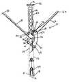
- FIGS. 1A-Brespectively show a side view and a top view of the dual action rod reducing and locking device in an open position; that is the first actuation lever is in an open position and if activated can effect the bone screw head grasping process and the rod reducing process.
- the second actuation leveris an open position and if activated can effect the process of locking the rod into position in the bone screw head after the rod has been so positioned.
- FIGS. 2A-Brespectively show a side view and a top view of the dual action rod reducing and locking device having the first actuation lever in a closed position; that is the first actuation lever is in a closed position and having been moved inward it has effected the bone screw head grasping process and the rod reducing process.
- the second actuation leveris in an open position and if activated can effect the process of locking the rod into position in the bone screw head after the rod has been so positioned.
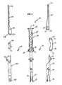
- FIGS. 3A-Crespectively show a side, back, and top view of the dual action rod reducing and locking device in a closed position; that is the first actuation lever is in a closed position and having been moved inward it has effected the bone screw head grasping process and the rod reducing process.
- the second actuation leveris in a closed position; that is having been moved inward it has effected the process of locking the rod into position in the bone screw head after it had been so positioned.
- FIG. 4shows the disassembled dual action rod reducing and locking device from a side perspective.
- FIGS. 5A-Brespectively show a side view and a cross-sectional view along the longitudinal axis of the dual action rod reducing and locking device in a closed position.
- FIGS. 6A-Drespectively show a side view, and cross-sectional views along the transverse axis at different levels along the length of the dual action rod reducing and locking device in a closed position.
- FIGS. 7A-Drespectively show a back view and cross-sectional views along the transverse axis at different levels along the length of the dual action rod reducing and locking device in a closed position.
- the deviceas generally shown at 10 in all of the accompanying figures is a dual action rod reducing and locking device that requires only the sequential movement of two separate activation levers on a single instrument to first position a rod into the head of a bone screw and second to lock the rod into place in the head of the bone screw.
- the deviceis an elongated multi-layered tubular instrument that includes an elongated central structure 12 about which at certain positions other components of the device 10 are either attached or circumferentially disposed.
- the central structure 12can be tubular with a central structure lumen 14 extending from a central structure first end 16 to a central structure second end 18 .
- the central structure lumen 14can be sized to permit the passage of other instruments as needed.
- An upper portion of the central structure 12 that terminates at or near the central structure first end 16is configured to serve as a handle 20 for the device 10 .
- the handle 20 of the deviceextends from a position near the first end 16 to position that approaches toward the central portion of the device 10 .
- a rod reducing sleeve 22Located adjacent to the central structure 12 and circumferentially disposed around at least a portion of the lower part of the central structure 12 is a rod reducing sleeve 22 that is sized and configured to freely move along the longitudinal axis of the device 10 .
- the rod reducing sleeve 22is constructed to be as thin and light weight as possible to facilitate insertion of the device into the surgical site and to promote ease of manual use of the device; however, the structure of the rod reducing sleeve 22 is strong enough to maintain its integrity during the rod reducing process of the device 10 when the rod reducing sleeve 22 will be forced into contact with a rod and must then transfer manual force against the rod so as to position it into a receiving notch in the head of a bone screw.
- the rod reducing sleeve 22is sufficiently long so as to extend from a position below the handle 20 of the device 10 to a position at or near the second end 18 of the central structure 12 .
- a rod reducing actuator 24is preferably configured as a lever although other actuating devices can also be used.
- the rod reducing actuator 24has a first end 26 that, when in an open position, as shown in FIGS. 1A-B can be extended away from or laterally from the device 10 and a rod reducing actuator 24 second end 28 , that is generally more medially directed to the device 10 .
- the rod reducing actuator 24is pivotally attached to the central structure 12 at rod reducer first pivot point 30 provided at a position approximate to the lower portion of the handle 20 of the device 10 .
- the rod reducer first pivot point 30 of the central structure 12corresponds to the actuator pivot point 32 , both of which are preferably pivot pin holes that are defined respectively in the central structure 12 and the rod reducing actuator 24 and connected by a pivot pin 34 . It is however, within the inventor's concept that any pivoting mechanism, such as a dimple and corresponding protrusion, can be used instead of the preferred pivot pin 34 . It is also within the inventors' concept that the rod reducer first pivot point 30 can be positioned anywhere along the length of the central structure 12 as long as effective leverage for the rod reducing actuator 24 can be achieved.
- a rod reducer second pivot point 36that is pivotally connected to a first end 38 of a rod reducer connecting arm 40 .
- a pivot pin 34is preferably used.
- a rod reducing connecting arm second pivot point 44is pivotally connected to a rod reducing sleeve pivot point 46 located near the upper portion of the rod reducing sleeve 22 .
- the rod reducing sleeve 22at its lowest end near the second end of the central structure 12 , is configured to provide a rod contact point 48 that preferably, as shown in the examples, will have a concave geometry complimentary to the arching shape of a rod cross-section.
- the second end 18 of the central structure 12terminates in at least one screw head grasping element 50 that is configured to grasp corresponding structures on the head of the bone screw into which the rod is to be positioned and locked.
- the central structure diameteris widened or increased just above the grasping elements 50 to form central structure cam surfaces 52 such that as the rod reducing sleeve 22 is moved downward around the outside of the central structure 12 , the inner wall of the rod reducing sleeve 22 can forcibly and compressively contact the cam surfaces 52 of the central structure thus forcing the screw head grasping elements inward into an engaging relationship with a properly positioned screw head.
- the surgeoncan then initiate the second action of the device, that of locking the rod in position in the screw head.
- the device 10is provided with a locking sleeve 54 that is circumferentially disposed around at least a portion of the rod reducing sleeve 22 .
- the locking sleeve 54is sized to freely move upward or downward along the longitudinal axis of the device 10 .
- the locking sleevehas a locking sleeve first end 56 approximately at the level of the upper portion of the rod reducing sleeve and a locking sleeve second end 58 approximately at the level of the central structure second end 18 .
- a locking actuator, 60which is preferably in the form of a lever actuator as shown in FIGS. 1A-B , 2 A-B, 3 A-B, 4 , 5 A-B, 6 A and 7 A, can be provided and pivotally attached to the opposite side of the central structure 12 from the rod reducing actuator 24 .
- the locking actuator 60can have a locking actuator first end 62 that when in the open position as shown in FIGS. 1A-B is located away from or lateral from the central structure 12 and a locking actuator second end 64 that is located more medial to the central structure 12 .
- the locking actuator 60is pivotally attached to the central structure 12 at a locking actuator first pivot point 66 that is at or near the second end of the locking actuator 60 .
- the locking actuator 60is provided with a second pivot point 68 that is pivotally attached to a locking actuator connecting arm 70 at a locking connecting arm first pivot point 72 .
- the locking connecting arm 70has a locking connecting arm first end 74 and a locking connecting arm second end 76 .
- At or near the locking actuator second end 76is a connecting arm second pivot point 78 .
- Pivotally connected to the locking actuator connecting arm 70 at the second pivot point 78is upper portion of the locking sleeve 54 .
- the pivotal connections disclosed above for the locking actuator 60 to the locking actuator connecting arm 70 and finally to the locking sleeve 54are such that when a surgeon squeezes the locking actuator lever 60 inward to a closed position adjacent to the handle 20 , as shown in FIGS. 3A-B , 5 A-B, 6 A and 7 A, the activation force is transmitted to the locking sleeve 54 so as to pull it upward along the outside of the rod reducing sleeve 22 .
- the locking sleeve 54is provided with at least one expansion slit 80 that extends from the locking sleeve second end 58 upward along the longitudinal axis of the device for a portion of the total length of the locking sleeve 54 .
- the second end of the locking sleeve 54is configured to slip fit over the external surface of a bone screw head and to engage complimentary structures on the bone screw head such that when the locking actuator 60 is squeezed inward to a closed position and the locking sleeve 54 is pulled upward, the inward bias of the locking sleeve 54 will maintain an inward holding pressure on the outer sleeve of the bone screw head and in doing so pull the outer sleeve of the taper lock bone screw upward while the rod reducing sleeve 22 holds the inner portion of the taper lock bone screw in place.
- the locking actuator 60can be moved fully inward into a closed or fully locked position.
- the device 10can be released from its grasp of the screw and removed from the surgical site.
- the partial lock positioncan be identified by the surgeon by providing a visual cue or indicia on the locking actuator lever 60 or by providing tactile or audible feedback to the user as the locking actuator 60 moves the mechanism past a cam or other frictional contact provided within the mechanism
- the device 10can be manufactured as integral components by methods known in the art, to include, for example, molding, casting, forming or extruding, and machining processes.
- the componentscan be manufactured using materials having sufficient strength, resiliency and biocompatibility as is well known in the art for such devices.
- suitable materials caminclude implant grade metallic materials, such as titanium, cobalt chromium alloys, stainless steel, or other suitable materials for this purpose.
- kitswhich includes the dual action device disclosed herein.
- a kitcan include two or more screws adaptable for use with the disclosed device, such as the taper lock screw disclosed and claimed in the commonly assigned and fully incorporated U.S. patent application Ser. Nos. 11/493,624 and 11/493,625.
- the kitcan contain surgical rods, such as, for example spinal rods. Additional devices such as cross-connectors, hooks, or links can also be included in the kit.
- Such a kitcan be provided with sterile packaging to facilitate opening and immediate use in an operating room.
Landscapes
- Health & Medical Sciences (AREA)
- Orthopedic Medicine & Surgery (AREA)
- Neurology (AREA)
- Life Sciences & Earth Sciences (AREA)
- Surgery (AREA)
- Heart & Thoracic Surgery (AREA)
- Engineering & Computer Science (AREA)
- Biomedical Technology (AREA)
- Nuclear Medicine, Radiotherapy & Molecular Imaging (AREA)
- Medical Informatics (AREA)
- Molecular Biology (AREA)
- Animal Behavior & Ethology (AREA)
- General Health & Medical Sciences (AREA)
- Public Health (AREA)
- Veterinary Medicine (AREA)
- Surgical Instruments (AREA)
Abstract
Description
Claims (18)
Priority Applications (4)
| Application Number | Priority Date | Filing Date | Title |
|---|---|---|---|
| US11/526,880US7931654B2 (en) | 2006-03-09 | 2006-09-26 | Dual action rod reducing and locking device and method |
| PCT/US2006/037455WO2007102846A1 (en) | 2006-03-09 | 2006-09-27 | Dual action rod reducing and locking device and method |
| EP06815455.8AEP2004105B1 (en) | 2006-03-09 | 2006-09-27 | Dual action rod reducing and locking device |
| US13/069,777US8377104B2 (en) | 2006-03-09 | 2011-03-23 | Dual action rod reducing and locking device and method |
Applications Claiming Priority (2)
| Application Number | Priority Date | Filing Date | Title |
|---|---|---|---|
| US78059606P | 2006-03-09 | 2006-03-09 | |
| US11/526,880US7931654B2 (en) | 2006-03-09 | 2006-09-26 | Dual action rod reducing and locking device and method |
Related Child Applications (1)
| Application Number | Title | Priority Date | Filing Date |
|---|---|---|---|
| US13/069,777DivisionUS8377104B2 (en) | 2006-03-09 | 2011-03-23 | Dual action rod reducing and locking device and method |
Publications (2)
| Publication Number | Publication Date |
|---|---|
| US20070213722A1 US20070213722A1 (en) | 2007-09-13 |
| US7931654B2true US7931654B2 (en) | 2011-04-26 |
Family
ID=38475176
Family Applications (2)
| Application Number | Title | Priority Date | Filing Date |
|---|---|---|---|
| US11/526,880Active2029-03-10US7931654B2 (en) | 2006-03-09 | 2006-09-26 | Dual action rod reducing and locking device and method |
| US13/069,777Active2027-02-14US8377104B2 (en) | 2006-03-09 | 2011-03-23 | Dual action rod reducing and locking device and method |
Family Applications After (1)
| Application Number | Title | Priority Date | Filing Date |
|---|---|---|---|
| US13/069,777Active2027-02-14US8377104B2 (en) | 2006-03-09 | 2011-03-23 | Dual action rod reducing and locking device and method |
Country Status (3)
| Country | Link |
|---|---|
| US (2) | US7931654B2 (en) |
| EP (1) | EP2004105B1 (en) |
| WO (1) | WO2007102846A1 (en) |
Cited By (16)
| Publication number | Priority date | Publication date | Assignee | Title |
|---|---|---|---|---|
| US20110202096A1 (en)* | 2010-02-12 | 2011-08-18 | John White | Spinal Rod and Screw Securing Apparatus and Method |
| US20110218581A1 (en)* | 2010-03-02 | 2011-09-08 | Warsaw Orthopedic, Inc. | Systems and methods for minimally invasive surgical procedures |
| US8702719B2 (en)* | 2008-10-16 | 2014-04-22 | Aesculap Implant Systems, Llc | Surgical instrument and method of use for inserting an implant between two bones |
| US9034046B2 (en) | 2007-10-30 | 2015-05-19 | Aesculap Implant Systems, Llc | Vertebral body replacement device and method for use to maintain a space between two vertebral bodies within a spine |
| US9192415B1 (en) | 2008-02-06 | 2015-11-24 | Nuvasive, Inc. | Systems and methods for holding and implanting bone anchors |
| US9198698B1 (en) | 2011-02-10 | 2015-12-01 | Nuvasive, Inc. | Minimally invasive spinal fixation system and related methods |
| US9486256B1 (en) | 2013-03-15 | 2016-11-08 | Nuvasive, Inc. | Rod reduction assemblies and related methods |
| US9974577B1 (en) | 2015-05-21 | 2018-05-22 | Nuvasive, Inc. | Methods and instruments for performing leveraged reduction during single position spine surgery |
| US10123829B1 (en) | 2015-06-15 | 2018-11-13 | Nuvasive, Inc. | Reduction instruments and methods |
| US10136927B1 (en) | 2013-03-15 | 2018-11-27 | Nuvasive, Inc. | Rod reduction assemblies and related methods |
| US10398481B2 (en) | 2016-10-03 | 2019-09-03 | Nuvasive, Inc. | Spinal fixation system |
| US10405896B2 (en)* | 2015-04-30 | 2019-09-10 | K2M, Inc. | Rod reducer |
| US10722276B2 (en) | 2013-03-14 | 2020-07-28 | K2M, Inc. | Taper lock hook |
| US10779866B2 (en) | 2016-12-29 | 2020-09-22 | K2M, Inc. | Rod reducer assembly |
| US11051861B2 (en) | 2018-06-13 | 2021-07-06 | Nuvasive, Inc. | Rod reduction assemblies and related methods |
| US11553947B2 (en) | 2019-07-16 | 2023-01-17 | Aesculap Implant Systems, Llc | Spinal deformity sequential persuader |
Families Citing this family (57)
| Publication number | Priority date | Publication date | Assignee | Title |
|---|---|---|---|---|
| US7887539B2 (en) | 2003-01-24 | 2011-02-15 | Depuy Spine, Inc. | Spinal rod approximators |
| US7988698B2 (en) | 2003-01-28 | 2011-08-02 | Depuy Spine, Inc. | Spinal rod approximator |
| US7842044B2 (en) | 2003-12-17 | 2010-11-30 | Depuy Spine, Inc. | Instruments and methods for bone anchor engagement and spinal rod reduction |
| ATE441376T1 (en)* | 2003-12-17 | 2009-09-15 | Depuy Spine Inc | INSTRUMENTS AND PROCEDURES FOR BONE ANCHOR PROCEDURES AND SPINAL BAR REDUCTION |
| US8267969B2 (en) | 2004-10-20 | 2012-09-18 | Exactech, Inc. | Screw systems and methods for use in stabilization of bone structures |
| US8226690B2 (en) | 2005-07-22 | 2012-07-24 | The Board Of Trustees Of The Leland Stanford Junior University | Systems and methods for stabilization of bone structures |
| US20060089651A1 (en)* | 2004-10-26 | 2006-04-27 | Trudeau Jeffrey L | Apparatus and method for anchoring a surgical rod |
| US7951175B2 (en) | 2005-03-04 | 2011-05-31 | Depuy Spine, Inc. | Instruments and methods for manipulating a vertebra |
| US7951172B2 (en) | 2005-03-04 | 2011-05-31 | Depuy Spine Sarl | Constrained motion bone screw assembly |
| US20060293692A1 (en) | 2005-06-02 | 2006-12-28 | Whipple Dale E | Instruments and methods for manipulating a spinal fixation element |
| US8523865B2 (en) | 2005-07-22 | 2013-09-03 | Exactech, Inc. | Tissue splitter |
| US7771430B2 (en)* | 2005-09-29 | 2010-08-10 | K2M, Inc. | Single action anti-torque rod reducer |
| US7918857B2 (en)* | 2006-09-26 | 2011-04-05 | Depuy Spine, Inc. | Minimally invasive bone anchor extensions |
| US8096996B2 (en) | 2007-03-20 | 2012-01-17 | Exactech, Inc. | Rod reducer |
| US20080172062A1 (en)* | 2007-01-12 | 2008-07-17 | Depuy Spine, Inc. | Bone anchor manipulation device |
| US8308774B2 (en) | 2007-02-14 | 2012-11-13 | Pioneer Surgical Technology, Inc. | Spinal rod reducer and cap insertion apparatus |
| US8172847B2 (en) | 2007-03-29 | 2012-05-08 | Depuy Spine, Inc. | In-line rod reduction device and methods |
| US8961523B2 (en) | 2007-07-13 | 2015-02-24 | K2M, Inc. | Rod reduction device and method of use |
| US7887541B2 (en)* | 2007-07-26 | 2011-02-15 | Depuy Spine, Inc. | Spinal rod reduction instruments and methods for use |
| ES2348814T3 (en) | 2007-07-31 | 2010-12-15 | Biedermann Motech Gmbh | ANCHORAGE DEVICE Ã “SEO. |
| US8790348B2 (en) | 2007-09-28 | 2014-07-29 | Depuy Spine, Inc. | Dual pivot instrument for reduction of a fixation element and method of use |
| US8113847B2 (en) | 2007-10-23 | 2012-02-14 | K2M, Inc. | Spinal surgery modeling system |
| WO2009055541A1 (en)* | 2007-10-23 | 2009-04-30 | K2M, Inc. | Implant insertion tool |
| US8235997B2 (en) | 2008-01-29 | 2012-08-07 | Pioneer Surgical Technology, Inc. | Rod locking instrument |
| US8608746B2 (en) | 2008-03-10 | 2013-12-17 | DePuy Synthes Products, LLC | Derotation instrument with reduction functionality |
| US8709015B2 (en)* | 2008-03-10 | 2014-04-29 | DePuy Synthes Products, LLC | Bilateral vertebral body derotation system |
| US10973556B2 (en) | 2008-06-17 | 2021-04-13 | DePuy Synthes Products, Inc. | Adjustable implant assembly |
| AU2009261934B2 (en)* | 2008-06-27 | 2014-09-04 | K2M, Inc. | System and method for performing spinal surgery |
| FR2937855B1 (en) | 2008-11-05 | 2010-12-24 | Warsaw Orthopedic Inc | PROGRESSIVE INTRODUCTION INSTRUMENT FOR A VERTEBRAL ROD. |
| CN102256558A (en)* | 2008-12-17 | 2011-11-23 | 斯恩蒂斯有限公司 | Rod reducer apparatus for spinal corrective surgery |
| US8206394B2 (en) | 2009-05-13 | 2012-06-26 | Depuy Spine, Inc. | Torque limited instrument for manipulating a spinal rod relative to a bone anchor |
| US8235998B2 (en)* | 2009-08-17 | 2012-08-07 | Warsaw Orthopedic, Inc. | Instruments and methods for in situ bending of an elongate spinal implant |
| US8545505B2 (en)* | 2010-01-15 | 2013-10-01 | Pioneer Surgical Technology, Inc. | Low friction rod persuader |
| EP2384709B1 (en) | 2010-05-05 | 2012-09-05 | Biedermann Technologies GmbH & Co. KG | Receiving part for receiving a rod for coupling the rod to a bone anchoring element, bone anchoring device, method and tool for assembling the same |
| US8512383B2 (en) | 2010-06-18 | 2013-08-20 | Spine Wave, Inc. | Method of percutaneously fixing a connecting rod to a spine |
| US8206395B2 (en)* | 2010-06-18 | 2012-06-26 | Spine Wave, Inc. | Surgical instrument and method for the distraction or compression of bones |
| US8685029B2 (en) | 2010-09-27 | 2014-04-01 | DePuy Synthes Products, LLC | Rod reduction instrument and methods of rod reduction |
| US8764756B2 (en) | 2011-02-22 | 2014-07-01 | K2M, Inc. | Single action anti-torque rod reducer |
| US8403933B2 (en)* | 2011-05-13 | 2013-03-26 | Synthes Usa, Llc | Locking cap dispenser |
| US8998807B2 (en)* | 2011-10-24 | 2015-04-07 | Warsaw Orthopedic, Inc. | Retractor extensions and methods of use |
| US9451998B2 (en)* | 2012-08-17 | 2016-09-27 | Warsaw Orthopedic, Inc. | Spinal implant system and method |
| WO2014074389A1 (en)* | 2012-11-06 | 2014-05-15 | Alphatec Spine, Inc. | Instrument and method for in situ rod adjustment |
| US9918752B2 (en)* | 2012-11-29 | 2018-03-20 | Warsaw Orthopedic, Inc. | Spinal implant system and method |
| US9675386B2 (en) | 2013-03-11 | 2017-06-13 | K2M, Inc. | Flexible fastening system |
| EP3054871B1 (en) | 2013-10-07 | 2022-05-18 | K2M, Inc. | Rod reducer |
| EP3047811B1 (en) | 2015-01-15 | 2022-05-18 | K2M, Inc. | Rod reducer |
| US10117678B2 (en) | 2015-05-28 | 2018-11-06 | K2M, Inc. | Surgical system for bone screw insertion and rod reduction |
| US9918755B2 (en) | 2015-06-29 | 2018-03-20 | DePuy Synthes Products, Inc. | Implant dispenser |
| US10524843B2 (en) | 2016-05-06 | 2020-01-07 | K2M, Inc. | Rotation shaft for a rod reducer |
| EP3525699B1 (en) | 2016-10-11 | 2023-07-26 | K2M, Inc. | Spinal implant |
| DE102016224503B3 (en)* | 2016-12-08 | 2018-05-24 | Premiere Medical Gmbh | Surgical reduction instrument |
| US10485590B2 (en) | 2017-01-18 | 2019-11-26 | K2M, Inc. | Rod reducing device |
| US10966762B2 (en) | 2017-12-15 | 2021-04-06 | Medos International Sarl | Unilateral implant holders and related methods |
| US11291481B2 (en) | 2019-03-21 | 2022-04-05 | Medos International Sarl | Rod reducers and related methods |
| USD1004774S1 (en) | 2019-03-21 | 2023-11-14 | Medos International Sarl | Kerrison rod reducer |
| US11291482B2 (en) | 2019-03-21 | 2022-04-05 | Medos International Sarl | Rod reducers and related methods |
| EP4240262B1 (en) | 2020-11-09 | 2024-12-04 | Medos International Sàrl | Biplanar forceps reducers |
Citations (9)
| Publication number | Priority date | Publication date | Assignee | Title |
|---|---|---|---|---|
| US5020519A (en)* | 1990-12-07 | 1991-06-04 | Zimmer, Inc. | Sagittal approximator |
| US5910141A (en)* | 1997-02-12 | 1999-06-08 | Sdgi Holdings, Inc. | Rod introduction apparatus |
| US6790209B2 (en)* | 2001-07-03 | 2004-09-14 | Sdgi Holdings, Inc. | Rod reducer instruments and methods |
| US20050192570A1 (en) | 2004-02-27 | 2005-09-01 | Jackson Roger P. | Orthopedic implant rod reduction tool set and method |
| US20050261702A1 (en)* | 2004-03-09 | 2005-11-24 | Showa Ika Kohgyo Co., Ltd. | Auxiliary instrument for fixing rod |
| US20060089651A1 (en)* | 2004-10-26 | 2006-04-27 | Trudeau Jeffrey L | Apparatus and method for anchoring a surgical rod |
| US20060200132A1 (en)* | 2005-03-04 | 2006-09-07 | Chao Nam T | Instruments and methods for manipulating a vertebra |
| US20070016192A1 (en)* | 2005-05-04 | 2007-01-18 | Woods Richard W | Polyaxial surgical rod fixation assembly |
| US20070093849A1 (en)* | 2005-09-29 | 2007-04-26 | Jones Scott A | Single action anti-torque rod reducer |
Family Cites Families (4)
| Publication number | Priority date | Publication date | Assignee | Title |
|---|---|---|---|---|
| FR2677242A1 (en)* | 1991-06-05 | 1992-12-11 | Jeanson Jean Francois | Push-bar device for spinal support |
| US20040267275A1 (en)* | 2003-06-26 | 2004-12-30 | Cournoyer John R. | Spinal implant holder and rod reduction systems and methods |
| US7988694B2 (en) | 2005-09-29 | 2011-08-02 | K2M, Inc. | Spinal fixation system having locking and unlocking devices for use with a multi-planar, taper lock screw |
| US8162991B2 (en) | 2006-07-27 | 2012-04-24 | K2M, Inc. | Multi-planar, taper lock screw |
- 2006
- 2006-09-26USUS11/526,880patent/US7931654B2/enactiveActive
- 2006-09-27WOPCT/US2006/037455patent/WO2007102846A1/enactiveApplication Filing
- 2006-09-27EPEP06815455.8Apatent/EP2004105B1/enactiveActive
- 2011
- 2011-03-23USUS13/069,777patent/US8377104B2/enactiveActive
Patent Citations (10)
| Publication number | Priority date | Publication date | Assignee | Title |
|---|---|---|---|---|
| US5020519A (en)* | 1990-12-07 | 1991-06-04 | Zimmer, Inc. | Sagittal approximator |
| US5910141A (en)* | 1997-02-12 | 1999-06-08 | Sdgi Holdings, Inc. | Rod introduction apparatus |
| US6790209B2 (en)* | 2001-07-03 | 2004-09-14 | Sdgi Holdings, Inc. | Rod reducer instruments and methods |
| US20050192570A1 (en) | 2004-02-27 | 2005-09-01 | Jackson Roger P. | Orthopedic implant rod reduction tool set and method |
| US7160300B2 (en)* | 2004-02-27 | 2007-01-09 | Jackson Roger P | Orthopedic implant rod reduction tool set and method |
| US20050261702A1 (en)* | 2004-03-09 | 2005-11-24 | Showa Ika Kohgyo Co., Ltd. | Auxiliary instrument for fixing rod |
| US20060089651A1 (en)* | 2004-10-26 | 2006-04-27 | Trudeau Jeffrey L | Apparatus and method for anchoring a surgical rod |
| US20060200132A1 (en)* | 2005-03-04 | 2006-09-07 | Chao Nam T | Instruments and methods for manipulating a vertebra |
| US20070016192A1 (en)* | 2005-05-04 | 2007-01-18 | Woods Richard W | Polyaxial surgical rod fixation assembly |
| US20070093849A1 (en)* | 2005-09-29 | 2007-04-26 | Jones Scott A | Single action anti-torque rod reducer |
Non-Patent Citations (1)
| Title |
|---|
| International Search Report issued in International Appl. No. PCT/US06/37455 on May 15, 2007, 3 pages. |
Cited By (42)
| Publication number | Priority date | Publication date | Assignee | Title |
|---|---|---|---|---|
| US9034046B2 (en) | 2007-10-30 | 2015-05-19 | Aesculap Implant Systems, Llc | Vertebral body replacement device and method for use to maintain a space between two vertebral bodies within a spine |
| US10806595B2 (en) | 2007-10-30 | 2020-10-20 | Aesculap Implant Systems, Llc | Vertebral body replacement device and method for use to maintain a space between two vertebral bodies within a spine |
| US10881527B2 (en) | 2007-10-30 | 2021-01-05 | Aesculap Implant Systems, Llc | Vertebral body replacement device and method for use to maintain a space between two vertebral bodies within a spine |
| US9492208B1 (en) | 2008-02-06 | 2016-11-15 | Nuvasive, Inc. | Systems and methods for holding and implanting bone anchors |
| US9192415B1 (en) | 2008-02-06 | 2015-11-24 | Nuvasive, Inc. | Systems and methods for holding and implanting bone anchors |
| US12285195B2 (en) | 2008-02-06 | 2025-04-29 | Globus Medical Inc. | Systems and methods for introducing a bone anchor |
| US10426526B2 (en) | 2008-02-06 | 2019-10-01 | Nuvasive, Inc. | Systems and methods for introducing a bone anchor |
| US11311320B2 (en) | 2008-02-06 | 2022-04-26 | Nuvasive, Inc. | Systems and methods for introducing a bone anchor |
| US9757166B1 (en) | 2008-02-06 | 2017-09-12 | Nuvasive, Inc. | Systems and methods for holding and implanting bone anchors |
| US10004544B2 (en) | 2008-02-06 | 2018-06-26 | Nuvasive, Inc. | Systems and methods for introducing a bone anchor |
| US8702719B2 (en)* | 2008-10-16 | 2014-04-22 | Aesculap Implant Systems, Llc | Surgical instrument and method of use for inserting an implant between two bones |
| US8900240B2 (en) | 2010-02-12 | 2014-12-02 | Pioneer Surgical Technology, Inc. | Spinal rod and screw securing apparatus and method |
| US20110202096A1 (en)* | 2010-02-12 | 2011-08-18 | John White | Spinal Rod and Screw Securing Apparatus and Method |
| US8323286B2 (en)* | 2010-03-02 | 2012-12-04 | Warsaw Orthopedic, Inc. | Systems and methods for minimally invasive surgical procedures |
| US20110218581A1 (en)* | 2010-03-02 | 2011-09-08 | Warsaw Orthopedic, Inc. | Systems and methods for minimally invasive surgical procedures |
| US11406429B2 (en) | 2011-02-10 | 2022-08-09 | Nuvasive, Inc. | Minimally invasive spinal fixation system and related methods |
| US9198698B1 (en) | 2011-02-10 | 2015-12-01 | Nuvasive, Inc. | Minimally invasive spinal fixation system and related methods |
| US9649140B1 (en) | 2011-02-10 | 2017-05-16 | Nuvasive, Inc. | Minimally invasive spinal fixation system and related methods |
| US11723698B2 (en) | 2011-02-10 | 2023-08-15 | Nuvasive, Inc. | Minimally invasive spinal fixation system and related methods |
| US10426527B2 (en) | 2011-02-10 | 2019-10-01 | Nuvasive, Inc. | Minimally invasive spinal fixation system and related methods |
| US10722276B2 (en) | 2013-03-14 | 2020-07-28 | K2M, Inc. | Taper lock hook |
| US11660128B2 (en) | 2013-03-15 | 2023-05-30 | Nuvasive, Inc. | Rod reduction assemblies and related methods |
| US10898241B2 (en) | 2013-03-15 | 2021-01-26 | Nuvasive, Inc. | Rod reduction assemblies and related methods |
| US10136927B1 (en) | 2013-03-15 | 2018-11-27 | Nuvasive, Inc. | Rod reduction assemblies and related methods |
| US9486256B1 (en) | 2013-03-15 | 2016-11-08 | Nuvasive, Inc. | Rod reduction assemblies and related methods |
| US10405896B2 (en)* | 2015-04-30 | 2019-09-10 | K2M, Inc. | Rod reducer |
| US9974577B1 (en) | 2015-05-21 | 2018-05-22 | Nuvasive, Inc. | Methods and instruments for performing leveraged reduction during single position spine surgery |
| US11771477B2 (en) | 2015-05-21 | 2023-10-03 | Nuvasive, Inc. | Methods and instruments for performing leveraged reduction during single position spine surgery |
| US10743921B2 (en) | 2015-06-15 | 2020-08-18 | Nuvasive, Inc. | Reduction instruments and methods |
| US10123829B1 (en) | 2015-06-15 | 2018-11-13 | Nuvasive, Inc. | Reduction instruments and methods |
| US12262929B2 (en) | 2015-06-15 | 2025-04-01 | Nuvasive, Inc. | Reduction instruments and methods |
| US11690657B2 (en) | 2015-06-15 | 2023-07-04 | Nuvasive, Inc. | Reduction instruments and methods |
| US11197697B2 (en) | 2016-10-03 | 2021-12-14 | Nuvasive, Inc. | Spinal fixation system |
| US10398481B2 (en) | 2016-10-03 | 2019-09-03 | Nuvasive, Inc. | Spinal fixation system |
| US11766281B2 (en) | 2016-10-03 | 2023-09-26 | Nuvasive, Inc. | Spinal fixation system |
| US12324611B2 (en) | 2016-10-03 | 2025-06-10 | Nuvasive, Inc. | Spinal fixation system |
| US12178479B2 (en) | 2016-12-29 | 2024-12-31 | K2M, Inc. | Rod reducer assembly |
| US10779866B2 (en) | 2016-12-29 | 2020-09-22 | K2M, Inc. | Rod reducer assembly |
| US20210282820A1 (en)* | 2018-06-13 | 2021-09-16 | Nuvasive, Inc. | Rod Reduction Assemblies and Related Methods |
| US11051861B2 (en) | 2018-06-13 | 2021-07-06 | Nuvasive, Inc. | Rod reduction assemblies and related methods |
| US12369954B2 (en)* | 2018-06-13 | 2025-07-29 | Nuvasive, Inc. | Rod reduction assemblies and related methods |
| US11553947B2 (en) | 2019-07-16 | 2023-01-17 | Aesculap Implant Systems, Llc | Spinal deformity sequential persuader |
Also Published As
| Publication number | Publication date |
|---|---|
| EP2004105A1 (en) | 2008-12-24 |
| WO2007102846A1 (en) | 2007-09-13 |
| US20070213722A1 (en) | 2007-09-13 |
| US20110224733A1 (en) | 2011-09-15 |
| EP2004105A4 (en) | 2012-05-30 |
| EP2004105B1 (en) | 2017-11-29 |
| US8377104B2 (en) | 2013-02-19 |
Similar Documents
| Publication | Publication Date | Title |
|---|---|---|
| US7931654B2 (en) | Dual action rod reducing and locking device and method | |
| US11903621B2 (en) | Rod reduction device and method of use | |
| US8834474B2 (en) | Single action anti-torque rod reducer | |
| US9247969B2 (en) | Rod reduction device | |
| EP1928331B1 (en) | Spinal fixation system having locking and unlocking devices for use with a multi-planar taper lock screw | |
| CA2803178C (en) | Spinal stabilization system |
Legal Events
| Date | Code | Title | Description |
|---|---|---|---|
| AS | Assignment | Owner name:K2M, INC., VIRGINIA Free format text:ASSIGNMENT OF ASSIGNORS INTEREST;ASSIGNORS:JONES, SCOTT A.;BARRUS, MICHAEL;ROCK, ANDY;REEL/FRAME:018694/0355;SIGNING DATES FROM 20061101 TO 20061115 Owner name:K2M, INC., VIRGINIA Free format text:ASSIGNMENT OF ASSIGNORS INTEREST;ASSIGNORS:JONES, SCOTT A.;BARRUS, MICHAEL;ROCK, ANDY;SIGNING DATES FROM 20061101 TO 20061115;REEL/FRAME:018694/0355 | |
| AS | Assignment | Owner name:SILICON VALLEY BANK, CALIFORNIA Free format text:SECURITY AGREEMENT;ASSIGNOR:K2M, INC.;REEL/FRAME:023032/0109 Effective date:20090729 Owner name:SILICON VALLEY BANK,CALIFORNIA Free format text:SECURITY AGREEMENT;ASSIGNOR:K2M, INC.;REEL/FRAME:023032/0109 Effective date:20090729 | |
| STCF | Information on status: patent grant | Free format text:PATENTED CASE | |
| AS | Assignment | Owner name:SILICON VALLEY BANK, MASSACHUSETTS Free format text:SECURITY INTEREST;ASSIGNORS:K2M, INC.;K2M HOLDING, INC.;K2M UK LIMITED;REEL/FRAME:029489/0327 Effective date:20121029 | |
| AS | Assignment | Owner name:K2M, INC., VIRGINIA Free format text:TERMINATION;ASSIGNOR:SILICON VALLEY BANK;REEL/FRAME:030918/0426 Effective date:20121029 | |
| FPAY | Fee payment | Year of fee payment:4 | |
| AS | Assignment | Owner name:SILICON VALLEY BANK, CALIFORNIA Free format text:FIRST AMENDMENT TO PATENT SECURITY AGREEMENT;ASSIGNORS:K2M, INC.;K2M UNLIMITED;K2M HOLDINGS, INC.;REEL/FRAME:034034/0097 Effective date:20141021 | |
| FEPP | Fee payment procedure | Free format text:ENTITY STATUS SET TO UNDISCOUNTED (ORIGINAL EVENT CODE: BIG.); ENTITY STATUS OF PATENT OWNER: LARGE ENTITY | |
| MAFP | Maintenance fee payment | Free format text:PAYMENT OF MAINTENANCE FEE, 8TH YEAR, LARGE ENTITY (ORIGINAL EVENT CODE: M1552); ENTITY STATUS OF PATENT OWNER: LARGE ENTITY Year of fee payment:8 | |
| AS | Assignment | Owner name:K2M UK LIMITED, UNITED KINGDOM Free format text:RELEASE BY SECURED PARTY;ASSIGNOR:SILICON VALLEY BANK;REEL/FRAME:047496/0001 Effective date:20181109 Owner name:K2M HOLDINGS, INC., VIRGINIA Free format text:RELEASE BY SECURED PARTY;ASSIGNOR:SILICON VALLEY BANK;REEL/FRAME:047496/0001 Effective date:20181109 Owner name:K2M, INC., VIRGINIA Free format text:RELEASE BY SECURED PARTY;ASSIGNOR:SILICON VALLEY BANK;REEL/FRAME:047496/0001 Effective date:20181109 | |
| MAFP | Maintenance fee payment | Free format text:PAYMENT OF MAINTENANCE FEE, 12TH YEAR, LARGE ENTITY (ORIGINAL EVENT CODE: M1553); ENTITY STATUS OF PATENT OWNER: LARGE ENTITY Year of fee payment:12 | |
| AS | Assignment | Owner name:ANKURA TRUST COMPANY, LLC, AS COLLATERAL AGENT, CONNECTICUT Free format text:PATENT SECURITY AGREEMENT;ASSIGNORS:K2M, INC.;VB SPINE US OPCO LLC;VB SPINE LLC;REEL/FRAME:071682/0116 Effective date:20250616 | |
| AS | Assignment | Owner name:TEXAS CAPITAL BANK, AS COLLATERAL AGENT, TEXAS Free format text:SECURITY INTEREST;ASSIGNORS:K2M, INC.;VB SPINE US OPCO LLC;REEL/FRAME:072340/0397 Effective date:20250401 |