US7931499B2 - Connector including flexible fingers and associated methods - Google Patents
Connector including flexible fingers and associated methodsDownload PDFInfo
- Publication number
- US7931499B2 US7931499B2US12/361,241US36124109AUS7931499B2US 7931499 B2US7931499 B2US 7931499B2US 36124109 AUS36124109 AUS 36124109AUS 7931499 B2US7931499 B2US 7931499B2
- Authority
- US
- United States
- Prior art keywords
- coaxial cable
- outer conductor
- connector
- insulator member
- cable connector
- Prior art date
- Legal status (The legal status is an assumption and is not a legal conclusion. Google has not performed a legal analysis and makes no representation as to the accuracy of the status listed.)
- Active, expires
Links
Images


Classifications
- H—ELECTRICITY
- H01—ELECTRIC ELEMENTS
- H01R—ELECTRICALLY-CONDUCTIVE CONNECTIONS; STRUCTURAL ASSOCIATIONS OF A PLURALITY OF MUTUALLY-INSULATED ELECTRICAL CONNECTING ELEMENTS; COUPLING DEVICES; CURRENT COLLECTORS
- H01R9/00—Structural associations of a plurality of mutually-insulated electrical connecting elements, e.g. terminal strips or terminal blocks; Terminals or binding posts mounted upon a base or in a case; Bases therefor
- H01R9/03—Connectors arranged to contact a plurality of the conductors of a multiconductor cable, e.g. tapping connections
- H01R9/05—Connectors arranged to contact a plurality of the conductors of a multiconductor cable, e.g. tapping connections for coaxial cables
- H01R9/0527—Connection to outer conductor by action of a resilient member, e.g. spring
- H—ELECTRICITY
- H01—ELECTRIC ELEMENTS
- H01R—ELECTRICALLY-CONDUCTIVE CONNECTIONS; STRUCTURAL ASSOCIATIONS OF A PLURALITY OF MUTUALLY-INSULATED ELECTRICAL CONNECTING ELEMENTS; COUPLING DEVICES; CURRENT COLLECTORS
- H01R9/00—Structural associations of a plurality of mutually-insulated electrical connecting elements, e.g. terminal strips or terminal blocks; Terminals or binding posts mounted upon a base or in a case; Bases therefor
- H01R9/03—Connectors arranged to contact a plurality of the conductors of a multiconductor cable, e.g. tapping connections
- H01R9/05—Connectors arranged to contact a plurality of the conductors of a multiconductor cable, e.g. tapping connections for coaxial cables
- H—ELECTRICITY
- H01—ELECTRIC ELEMENTS
- H01R—ELECTRICALLY-CONDUCTIVE CONNECTIONS; STRUCTURAL ASSOCIATIONS OF A PLURALITY OF MUTUALLY-INSULATED ELECTRICAL CONNECTING ELEMENTS; COUPLING DEVICES; CURRENT COLLECTORS
- H01R13/00—Details of coupling devices of the kinds covered by groups H01R12/70 or H01R24/00 - H01R33/00
- H01R13/62—Means for facilitating engagement or disengagement of coupling parts or for holding them in engagement
- H01R13/627—Snap or like fastening
- H01R13/6277—Snap or like fastening comprising annular latching means, e.g. ring snapping in an annular groove
- H—ELECTRICITY
- H01—ELECTRIC ELEMENTS
- H01R—ELECTRICALLY-CONDUCTIVE CONNECTIONS; STRUCTURAL ASSOCIATIONS OF A PLURALITY OF MUTUALLY-INSULATED ELECTRICAL CONNECTING ELEMENTS; COUPLING DEVICES; CURRENT COLLECTORS
- H01R13/00—Details of coupling devices of the kinds covered by groups H01R12/70 or H01R24/00 - H01R33/00
- H01R13/648—Protective earth or shield arrangements on coupling devices, e.g. anti-static shielding
- H01R13/658—High frequency shielding arrangements, e.g. against EMI [Electro-Magnetic Interference] or EMP [Electro-Magnetic Pulse]
- H—ELECTRICITY
- H01—ELECTRIC ELEMENTS
- H01R—ELECTRICALLY-CONDUCTIVE CONNECTIONS; STRUCTURAL ASSOCIATIONS OF A PLURALITY OF MUTUALLY-INSULATED ELECTRICAL CONNECTING ELEMENTS; COUPLING DEVICES; CURRENT COLLECTORS
- H01R24/00—Two-part coupling devices, or either of their cooperating parts, characterised by their overall structure
- H01R24/38—Two-part coupling devices, or either of their cooperating parts, characterised by their overall structure having concentrically or coaxially arranged contacts
- H01R24/40—Two-part coupling devices, or either of their cooperating parts, characterised by their overall structure having concentrically or coaxially arranged contacts specially adapted for high frequency
- H01R24/56—Two-part coupling devices, or either of their cooperating parts, characterised by their overall structure having concentrically or coaxially arranged contacts specially adapted for high frequency specially adapted to a specific shape of cables, e.g. corrugated cables, twisted pair cables, cables with two screens or hollow cables
- H01R24/566—Hollow cables
- H—ELECTRICITY
- H01—ELECTRIC ELEMENTS
- H01R—ELECTRICALLY-CONDUCTIVE CONNECTIONS; STRUCTURAL ASSOCIATIONS OF A PLURALITY OF MUTUALLY-INSULATED ELECTRICAL CONNECTING ELEMENTS; COUPLING DEVICES; CURRENT COLLECTORS
- H01R13/00—Details of coupling devices of the kinds covered by groups H01R12/70 or H01R24/00 - H01R33/00
- H01R13/46—Bases; Cases
- H01R13/52—Dustproof, splashproof, drip-proof, waterproof, or flameproof cases
- H01R13/5202—Sealing means between parts of housing or between housing part and a wall, e.g. sealing rings
- H—ELECTRICITY
- H01—ELECTRIC ELEMENTS
- H01R—ELECTRICALLY-CONDUCTIVE CONNECTIONS; STRUCTURAL ASSOCIATIONS OF A PLURALITY OF MUTUALLY-INSULATED ELECTRICAL CONNECTING ELEMENTS; COUPLING DEVICES; CURRENT COLLECTORS
- H01R13/00—Details of coupling devices of the kinds covered by groups H01R12/70 or H01R24/00 - H01R33/00
- H01R13/46—Bases; Cases
- H01R13/52—Dustproof, splashproof, drip-proof, waterproof, or flameproof cases
- H01R13/5205—Sealing means between cable and housing, e.g. grommet
- H—ELECTRICITY
- H01—ELECTRIC ELEMENTS
- H01R—ELECTRICALLY-CONDUCTIVE CONNECTIONS; STRUCTURAL ASSOCIATIONS OF A PLURALITY OF MUTUALLY-INSULATED ELECTRICAL CONNECTING ELEMENTS; COUPLING DEVICES; CURRENT COLLECTORS
- H01R13/00—Details of coupling devices of the kinds covered by groups H01R12/70 or H01R24/00 - H01R33/00
- H01R13/62—Means for facilitating engagement or disengagement of coupling parts or for holding them in engagement
- H01R13/622—Screw-ring or screw-casing
- H—ELECTRICITY
- H01—ELECTRIC ELEMENTS
- H01R—ELECTRICALLY-CONDUCTIVE CONNECTIONS; STRUCTURAL ASSOCIATIONS OF A PLURALITY OF MUTUALLY-INSULATED ELECTRICAL CONNECTING ELEMENTS; COUPLING DEVICES; CURRENT COLLECTORS
- H01R2103/00—Two poles
- H—ELECTRICITY
- H01—ELECTRIC ELEMENTS
- H01R—ELECTRICALLY-CONDUCTIVE CONNECTIONS; STRUCTURAL ASSOCIATIONS OF A PLURALITY OF MUTUALLY-INSULATED ELECTRICAL CONNECTING ELEMENTS; COUPLING DEVICES; CURRENT COLLECTORS
- H01R2201/00—Connectors or connections adapted for particular applications
- H01R2201/02—Connectors or connections adapted for particular applications for antennas
- H—ELECTRICITY
- H01—ELECTRIC ELEMENTS
- H01R—ELECTRICALLY-CONDUCTIVE CONNECTIONS; STRUCTURAL ASSOCIATIONS OF A PLURALITY OF MUTUALLY-INSULATED ELECTRICAL CONNECTING ELEMENTS; COUPLING DEVICES; CURRENT COLLECTORS
- H01R24/00—Two-part coupling devices, or either of their cooperating parts, characterised by their overall structure
- H01R24/38—Two-part coupling devices, or either of their cooperating parts, characterised by their overall structure having concentrically or coaxially arranged contacts
- H01R24/40—Two-part coupling devices, or either of their cooperating parts, characterised by their overall structure having concentrically or coaxially arranged contacts specially adapted for high frequency
- H01R24/56—Two-part coupling devices, or either of their cooperating parts, characterised by their overall structure having concentrically or coaxially arranged contacts specially adapted for high frequency specially adapted to a specific shape of cables, e.g. corrugated cables, twisted pair cables, cables with two screens or hollow cables
- H01R24/564—Corrugated cables
- Y—GENERAL TAGGING OF NEW TECHNOLOGICAL DEVELOPMENTS; GENERAL TAGGING OF CROSS-SECTIONAL TECHNOLOGIES SPANNING OVER SEVERAL SECTIONS OF THE IPC; TECHNICAL SUBJECTS COVERED BY FORMER USPC CROSS-REFERENCE ART COLLECTIONS [XRACs] AND DIGESTS
- Y10—TECHNICAL SUBJECTS COVERED BY FORMER USPC
- Y10T—TECHNICAL SUBJECTS COVERED BY FORMER US CLASSIFICATION
- Y10T29/00—Metal working
- Y10T29/49—Method of mechanical manufacture
- Y10T29/49002—Electrical device making
- Y10T29/49117—Conductor or circuit manufacturing
- Y10T29/49123—Co-axial cable
Definitions
- the present inventionrelates to the field of connectors, and, more particularly, to connectors for coaxial cables and related methods.
- Coaxial cablesare widely used to carry high frequency electrical signals. Coaxial cables enjoy a relatively high bandwidth, low signal losses, are mechanically robust, and are relatively low cost.
- One particularly advantageous use of a coaxial cableis for connecting electronics at a cellular or wireless base station to an antenna mounted at the top of a nearby antenna tower.
- the transmitter located in an equipment sheltermay be connected to a transmit antenna supported by the antenna tower.
- the receiveris also connected to its associated receiver antenna by a coaxial cable path.
- a typical installationincludes a relatively large diameter coaxial cable extending between the equipment shelter and the top of the antenna tower to thereby reduce signal losses.
- Some coaxial cablesinclude a smooth outer conductor while other coaxial cables instead have a corrugated outer conductor.
- These coaxial cablesalso have an inner conductor and a dielectric between the outer conductor and the inner conductor.
- Some inner conductorsare hollow, while other inner conductors are formed around an inner conductor dielectric core.
- a typical connector for such a coaxial cableincludes a connector housing to make an electrical connection to the outer conductor and a center contact to make electrical connection to the inner conductor of the coaxial cable.
- Such a connectormay also include a back nut that is positioned onto the end of the outer conductor and adjacent the outer insulating jacket portion of the coaxial cable.
- U.S. Pat. No. 7,435,135 to Wlosdiscloses a coaxial cable connector with spring finger back nut telescopically coupled via threads to a coaxial cable end.
- a nut bore in the spring finger back nutreceives an outer conductor of the coaxial cable.
- U.S. Pat. No. 5,795,188 to Harwathdiscloses a connector for a coaxial cable having a corrugated outer conductor.
- the connectorincludes a connector housing defining a radially outer ramp to contact the inside surface of a flared end portion of an outer conductor of the coaxial cable.
- a clamping ringis in the corrugation adjacent to the flared end portion of the outer conductor. The clamping ring presses the outer surface of the outer conductor against the radially outer ramp to provide electrical contact therebetween.
- U.S. Pat. No. 7,011,546 to Vaccarodiscloses a connector for a coaxial cable having a smooth outer conductor.
- the connectorincludes a connector housing, a back nut threadingly engaging a rearward end of the connector housing, a ferrule gripping and advancing an end of the coaxial cable into the connector housing as the back nut is tightened, and an insulator member positioned within a medial portion of the connector housing.
- the insulator memberhas a bore extending therethrough and includes a forward disk portion, a rearward disk portion, a ring portion connecting the forward and disk portions together, and a tubular outer conductor support portion extending rearwardly from the rearward disk portion for supporting an interior surface of the outer conductor of the coaxial cable.
- U.S. Pat. No. 7,077,700 to Henningsendiscloses a coaxial cable connector including a removable back nut, an outer body, and a center conductor supported within the outer body by a dielectric.
- An uncompressible clamp ringis rotatably disposed within the central bore of the back nut.
- a prepared end of a coaxial cableis inserted through the back nut, and the end portion of the outer conductor of the coaxial cable is flared outwardly. As the back nut is tightened onto the outer body, the flared end of the outer conductor is clamped between mating clamping surfaces formed on the clamp ring and the outer body.
- connectorsmay facilitate easy installation and that may retain a good electrical and mechanical contact with the coaxial cable under a variety of operating conditions. Further, a need remains for connectors that may be securely attached to a coaxial cable and that are sealed against debris and moisture.
- a coaxial cable connectorto be attached to a coaxial cable comprising an inner conductor, an outer conductor, and a dielectric therebetween.
- the connectormay comprise a connector housing defining a ramp to receive the outer conductor thereagainst and a back nut comprising a ring base and a plurality of flexible fingers extending forwardly therefrom to clamp against the outer conductor opposite the ramp.
- Each of the plurality of flexible fingersmay have a bend therein. Additionally or alternatively, each of the plurality of fingers may have a portion with a reduced thickness to deflect in response to longitudinal compression of that flexible finger. This advantageously allows the coaxial cable connector to be used with a variety of coaxial cables having outer conductors of different thicknesses.
- the connector housing and the back nutmay include respective portions defining a positive stop when fully engaged.
- the positive stopmay allow the connector to be attached to the coaxial cable without a torque wrench or other torque limiting tool, as the positive stop indicates to the installer when to stop tightening the back nut and the connector housing together.
- At least one insulator membermay be in the connector housing for carrying the center contact and comprising a radially outer support portion to radially support the outer conductor opposite the plurality of flexible fingers. This radial support portion supports the outer conductor radially outwardly as the plurality of flexible fingers urge the outer conductor radially inwardly.
- At least one of the plurality of flexible fingersmay have a plurality of serrations extending from a surface thereof to engage the outer conductor. These serrations may ‘bite’ into the outer conductor to thereby securely attach the connector housing on the coaxial cable and increase coaxial cable retention torque.
- the serrationshelp prevent longitudinal movement of the coaxial cable connector relative to the coaxial cable due to tensile forces.
- the serrationsreduce intramodulation distortion (IMD) by reducing radial movement of the coaxial cable connector about the coaxial cable.
- IMDintramodulation distortion
- the connector housingmay comprise an enlarged diameter tool engaging portion and the back nut may comprises a rearward end.
- the positive stopmay be defined by the enlarged diameter tool engaging portion and the rearward end.
- the at least one insulator membermay comprise a first insulator member having a central opening defined therein to carry the center contact.
- the at least one insulator membermay further comprise a second insulator member longitudinally spaced apart from, and positioned forwardly of, the insulator member in the connector housing and also having a central opening defined therein to carry the center contact.
- the rampmay have a stair-stepped shape or a knurled shape.
- This stair-stepped or knurled shapemay present an increased friction surface to the outer conductor to help prevent unwanted movement of the outer conductor.
- This stair-stepped or knurled shapemay also enhance the electrical contact with the outer conductor.
- At least one sealing ringmay be carried within the back nut. This sealing ring may seal the interior of the connector housing and the back nut from moisture and debris.
- the insulator membermay comprise a retaining projection extending therefrom and an annular groove may be defined on a radially inner surface of the connector housing to receive the retaining projection. This retaining projection helps to securely locate and retain the insulator member in the back nut.
- the connector housingmay comprise a rearward portion threadingly received within a forward portion of the back nut.
- a method aspectis directed to a method of making a connector to be attached to a coaxial cable comprising an inner conductor, an outer conductor, and a dielectric therebetween.
- the methodmay comprise forming a connector housing to have a ramp to receive the outer conductor thereagainst and forming a back nut comprising a ring base and a plurality of flexible fingers extending forwardly therefrom to clamp against the outer conductor opposite the ramp.
- the connector housing and the back nutmay be formed to have respective portions defining a positive stop when fully engaged.
- a center contactmay be formed to be coupled to the inner conductor.
- At least one insulator membermay be formed to be positioned in the connector housing for carrying the center contact and comprising a radially outer support portion to radially support the outer conductor opposite the plurality of fingers.
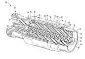
- FIG. 1is a perspective cutaway view of a coaxial cable connector installed on the end of a coaxial cable having a smooth outer conductor, in accordance with the present invention.
- FIG. 2is a longitudinal cross-sectional view of the coaxial cable connector of FIG. 1 .
- FIG. 3is an exploded longitudinal cross-sectional view of the connector of FIG. 1 .
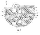
- FIG. 4is a greatly enlarged longitudinal cross-sectional view of the coaxial cable connector of FIG. 1 .
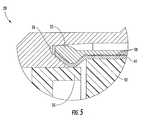
- FIG. 5is a greatly enlarged longitudinal cross-sectional view of the flexible finger and ramp of the coaxial cable connector of FIG. 1 .
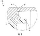
- FIG. 6is a greatly enlarged longitudinal cross sectional view of the ramp of the coaxial cable connector of FIG. 1 wherein the flexible fingers are not shown for clarity.
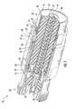
- FIG. 7is a perspective view of the back nut of the coaxial cable connector of FIG. 1 .
- FIG. 8is a side view of the back nut of the coaxial cable connector of FIG. 1 .
- FIG. 9is an enlarged side view of a flexible finger of the back nut of the coaxial cable connector of FIG. 1 .
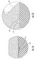
- FIG. 10is a perspective view of the insulator member of the coaxial cable connector of FIG. 1 .
- FIG. 11is a longitudinal cross sectional view of the insulator member of the coaxial cable connector of FIG. 1 .
- FIG. 12is a longitudinal cross-sectional view of an alternative embodiment of a coaxial cable connector installed on the end of a coaxial cable having a smooth outer conductor, in accordance with the present invention.
- FIG. 13is a greatly enlarged longitudinal cross-sectional view of the coaxial cable connector of FIG. 12 .
- FIG. 14is a greatly enlarged longitudinal cross sectional view of the retaining projection and annular groove of the coaxial cable connector of FIG. 12 wherein the flexible fingers are not shown for clarity.
- FIG. 15is a greatly enlarged longitudinal cross sectional view of the retaining projection and insulator member of the coaxial cable connector of FIG. 12 .
- FIG. 16is a longitudinal cross-sectional view of yet another embodiment of a coaxial cable connector installed on the end of a coaxial cable having a smooth outer conductor, in accordance with the present invention.
- FIG. 17is a greatly enlarged longitudinal cross-sectional view of a flexible finger of the coaxial cable connector of FIG. 16 .
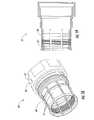
- FIG. 18is a perspective view of the back nut of FIG. 16 .
- FIG. 19is a side view of the back nut of FIG. 16 .
- FIG. 20is a perspective view of an alternative embodiment of the back nut of FIG. 1 .
- FIG. 21is a greatly enlarged longitudinal cross sectional view of the back nut of FIG. 17 .
- FIG. 22is an enlarged longitudinal cross sectional view of the back nut of FIG. 17 .
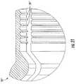
- FIG. 23is a side view of an alternative embodiment of the back nut of the present invention.
- FIG. 24is an enlarged view of a flexible finger of the back but of FIG. 23 .
- FIG. 25is an enlarged longitudinal cross sectional view of the back nut of FIG. 23 showing a flexible finger.
- the coaxial cable 40comprises an inner conductor 43 , an outer conductor 41 , and a dielectric 42 therebetween.
- the inner conductor 43is a hollow inner conductor with an inner conductor filament 45 , and an inner conductor dielectric 44 therebetween.
- the inner conductor 43may instead be a hollow inner conductor.
- the outer conductor 41is illustratively a smooth outer conductor with a flared end, but could be a corrugated outer conductor in other embodiments.
- the dielectrics 42 , 44may be foam dielectrics or other dielectrics as known to those skilled in the art.
- the connector 20includes an internally threaded back nut 23 to receive an externally threaded rearward end of a connector housing 22 .
- a forward o-ring 30 and a rearward o-ring 31are illustratively provided to seal respective forward and rearward interfaces adjacent the back nut 23 and reduce or prevent moisture ingress.
- the rearward o-ring 31is positioned within an o-ring pocket 32 .
- the connector housing 22defines a ramp 24 to receive the outer conductor 41 thereagainst.
- the ramp 24illustratively has stair-stepped surface, although the skilled artisan will understand that other ramp surfaces may be used.
- the ramp 24may have a knurled surface.
- the end of the coaxial cable 40is prepared so that the inner conductor 43 extends longitudinally outwardly beyond the end of the outer conductor 41 .
- portions of the dielectric 42are removed so that the inner surface of the outer conductor 41 is also exposed.
- the coaxial cable 40illustratively includes an outer insulation jacket 44 stripped back a distance so that outer end portions of the outer conductor 41 are exposed.
- the outer conductor 41is flared outwardly to define a flared end.
- a portion of the connector housing 22 and a portion of the back nut 23include respective portions defining a positive stop 29 when fully engaged. More particularly, the connector housing 22 comprises an enlarged diameter tool engaging portion 27 and the back nut 23 comprises a forward end 28 .
- the positive stop 29is defined by the enlarged diameter tool engaging portion 27 and the forward end 28 of the back nut 23 .
- the forward o-ring 30is radially inward of and adjacent to the positive stop 29 .
- the connector housing 22may have a rear portion to engage with a shoulder of the back nut 23 to define the positive stop 29 .
- the positive stop 29helps prevent overtightening of the engagement between the connector housing 22 and the back nut 23 that may generate compression and or shearing forces at potentially damaging levels.
- the positive stop 29therefore facilitates easy installation of the connector 20 on the coaxial cable 40 by eliminating the need for a torque wrench or other torque limiting tool.
- the back nut 23comprises a ring base 47 and a plurality of flexible fingers 25 extending forwardly therefrom to clamp against the outer conductor 41 opposite the ramp 24 .
- the flexible fingers 25are flexible in that they may be deflected radially and may bend axially. This axial bending helps facilitate the attachment of the coaxial cable connector 20 to coaxial cables 40 of varying thicknesses. Further, the flexible fingers 25 may be electrically conductive.
- the connector housing 22illustratively has a finger cavity 26 to receive the flexible fingers 25 .
- the plurality of flexible fingers 25are biased inwardly to compressibly clamp against the outer conductor 41 opposite the ramp 24 as the connector housing 22 and back nut 23 are engaged.
- This clampinghelps to provide an electrical connection between the outer conductor 41 and the ramp 14 by providing a constant contact pressure between the outer conductor and the ramp. By maintaining such a secure electrical connection, the intermodulation distortion of signals traveling through the coaxial cable 40 may be reduced.
- the flexible fingers 25advantageously maintain a sufficient clamping force on the outer conductor 41 even if the outer conductor changes shape or size due to thermal expansion or aluminum creep, for example, whereas an arrangement of two fixed and inflexible wedging surfaces to clamp the outer conductor might lose clamping force and contact pressure if the outer conductor were to change shape or size. Furthermore, by maintaining a constant clamping force on the outer conductor 41 , the flexible fingers 25 allow the connector 20 to be used with both smooth wall outer conductor coaxial cables 40 and corrugated outer conductor coaxial cables. In addition the flexible fingers 25 allow the connector 20 to be used on a variety of coaxial cables with different thicknesses, and on a variety of coaxial cables with outer conductors having different thicknesses.
- the flexible fingers 25each illustratively have a plurality of serrations 50 extending radially inwardly from a surface thereof. These serrations 50 ‘bite’ into the outer conductor to securely attach the connector housing 22 on the coaxial cable 40 and increase coaxial cable retention torque.
- the serrations 50help prevent longitudinal movement of the coaxial cable connector 20 relative to the coaxial cable due 40 to tensile forces.
- the serrations 50reduce intramodulation distortion (IMD) by reducing radial movement of the coaxial cable connector 20 about the coaxial cable 40 .
- IMDintramodulation distortion
- these serrations 50are illustratively angled so that the coaxial cable 40 is longitudinally advanced within the coaxial cable connector 20 as the connector housing 22 and back nut 23 are screwed together. Moreover, one side of the serrations 50 is illustratively perpendicular to the longitudinal axis of the flexible finger 25 , while the other side is angled with respect to the longitudinal axis of the flexible finger. Serrations 50 having such a shape may be formed by cutting the flexible fingers 25 using a thread cutter.
- the serrations 50 ′′′may have a knurled or diamond knurled shape.
- the tip of each flexible finger 25 ′′′may also have a knurled or diamond knurled shape. Such a knurled tip may help to grasp the end of the outer conductor 41 ′′ and to longitudinally advance the outer conductor as the connector housing 22 and back nut 23 are screwed together.
- a center contact 33is supported in the connector housing 22 by the insulator member 34 and is electrically connected to the inner conductor 43 .
- the insulator member 34is also carries the inner conductor 43 of the cable to reduce or prevent movement to thereby reduce IMD.
- the insulator member 34comprises a radially outer support portion 35 to radially support the outer conductor 41 opposite the flexible fingers 25 .
- This radial supportsupports the outer conductor 41 radially outwardly as the flexible fingers 25 urge the outer conductor radially inwardly.
- the radially outer support portion 35helps to reduce the chance of a loss of electrical contact between the outer conductor 41 and the ramp 24 due to flexing of the coaxial cable 40 or due to compression of the dielectric 42 .
- the illustrated insulator member 34is a monolithically formed one-piece unit. Such a monolithic construction helps to reduce the number of connector components and thereby reduce the overall cost of the connector 20 .
- the back nut 23has a retaining projection 51 that bites into the insulator member 34 , causing a depression 52 to form therein (see FIG. 14 ).
- This retaining projection 51helps to secure located and retain the insulator member 34 in the connector housing 22 .
- the insulator member 34may also be a two-piece unit in some applications.
- the retaining projection 51 ′bites into the insulator member 34 a ′, forming the depression 52 ′ therein.
- the insulator member 34 b ′has a retaining projection 53 ′ extending radially outwardly therefrom and the back nut 23 ′ has an annular groove 54 ′ defined on a radially inner surface thereof.
- the retaining projection 53 ′ of the insulator member 34 b ′fits in the annular groove 54 ′ and helps to positively locate and secure the insulator member 34 b ′ in the connector housing 22 ′.
- Other elements not specifically mentionedare indicated with prime notation and are similar to the elements described above with reference to FIG. 1 . Accordingly, those other elements require no further description herein.
- each of the flexible fingers 25 ′′has a bend 60 ′′ that deflects in response to longitudinal compression of that flexible finger 25 ′′ that deflects in response to longitudinal compression of that flexible finger.
- the flexible fingers 25 ′′may of course deflect inwardly or outwardly at the bend 60 ′′.
- This bendadvantageously allows the coaxial cable connector 25 ′′ to accommodate a wide variety of coaxial cables 40 ′′ having outer conductors 41 ′′ of different thicknesses by allowing the length of the flexible fingers 25 ′′ to self adjust.
- Other elements not specifically mentionedare indicated with double prime notation and are similar to the elements described above with reference to FIG. 1 . Accordingly, those other elements require no further description herein.
- the flexible fingers 25 ′′′′have a portion with a reduced thickness.
- the flexible fingers 25 ′′′′will deflect at this point in response to longitudinal compression of that flexible finger as the back nut 23 ′′′′ and connector housing are screwed together. This advantageously allows the coaxial cable connector to accommodate a wide variety of coaxial cables having outer conductors of different thicknesses by allowing the length of the flexible fingers to self adjust.
- a method of making a coaxial cable connector 20 to be attached to a coaxial cable 40 comprising an inner conductor 43 , an outer conductor 41 , and a dielectric 42 therebetweenis now described.
- the methodcomprises forming a connector housing 22 to have a ramp 24 to receive the outer conductor 41 thereagainst.
- the methodfurther includes forming a back nut 23 comprising a ring base 47 and a plurality of flexible fingers 25 extending forwardly therefrom to clamp against the outer conductor 41 opposite the ramp 24 .
- the connector housing 22 and the back nut 23are formed to have respective portions defining a positive stop 29 when fully engaged.
- a center contact 33is formed to be coupled to the inner conductor.
- At least one insulator member 34is formed to be positioned in the connector housing 22 for carrying the center contact 33 and comprises a radially outer support portion 35 to radially support the outer conductor 41 opposite the plurality of fingers 25 .
Landscapes
- Coupling Device And Connection With Printed Circuit (AREA)
Abstract
Description
Claims (27)
Priority Applications (7)
| Application Number | Priority Date | Filing Date | Title |
|---|---|---|---|
| US12/361,241US7931499B2 (en) | 2009-01-28 | 2009-01-28 | Connector including flexible fingers and associated methods |
| KR1020117020051AKR20110124762A (en) | 2009-01-28 | 2010-01-22 | Coaxial Cable Connectors and Flexible Methods Including Flexible Fingers |
| EP10705461AEP2392052A1 (en) | 2009-01-28 | 2010-01-22 | Coaxial cable connector including flexible fingers and associated methods |
| PCT/US2010/021728WO2010090882A1 (en) | 2009-01-28 | 2010-01-22 | Coaxial cable connector including flexible fingers and associated methods |
| JP2011548116AJP2012516544A (en) | 2009-01-28 | 2010-01-22 | Coaxial cable connector including flexible fingers and method associated with the coaxial cable connector |
| CN2010800099943ACN102341964A (en) | 2009-01-28 | 2010-01-22 | Coaxial cable connector including flexible fingers and related methods |
| BRPI1007362ABRPI1007362A2 (en) | 2009-01-28 | 2010-01-22 | coaxial cable connector including flexible fingers and associated methods |
Applications Claiming Priority (1)
| Application Number | Priority Date | Filing Date | Title |
|---|---|---|---|
| US12/361,241US7931499B2 (en) | 2009-01-28 | 2009-01-28 | Connector including flexible fingers and associated methods |
Publications (2)
| Publication Number | Publication Date |
|---|---|
| US20100190377A1 US20100190377A1 (en) | 2010-07-29 |
| US7931499B2true US7931499B2 (en) | 2011-04-26 |
Family
ID=42145106
Family Applications (1)
| Application Number | Title | Priority Date | Filing Date |
|---|---|---|---|
| US12/361,241Active2029-05-01US7931499B2 (en) | 2009-01-28 | 2009-01-28 | Connector including flexible fingers and associated methods |
Country Status (7)
| Country | Link |
|---|---|
| US (1) | US7931499B2 (en) |
| EP (1) | EP2392052A1 (en) |
| JP (1) | JP2012516544A (en) |
| KR (1) | KR20110124762A (en) |
| CN (1) | CN102341964A (en) |
| BR (1) | BRPI1007362A2 (en) |
| WO (1) | WO2010090882A1 (en) |
Cited By (6)
| Publication number | Priority date | Publication date | Assignee | Title |
|---|---|---|---|---|
| US20120058672A1 (en)* | 2010-09-02 | 2012-03-08 | Tyco Electronics Corporation | Electrical connector having shaped dielectric insert for controlling impedance |
| US20130203287A1 (en)* | 2012-02-06 | 2013-08-08 | John Mezzalingua Associates, Inc. | Port assembly connector for engaging a coaxial cable and an outer conductor |
| US8556655B2 (en)* | 2010-11-22 | 2013-10-15 | Andrew Llc | Friction weld coaxial connector |
| US10965070B2 (en)* | 2018-08-07 | 2021-03-30 | Jiangsu Hengxin Technology Co., Ltd. | Quick demountable high-reliability radio-frequency coaxial connector |
| US11075471B2 (en)* | 2014-02-11 | 2021-07-27 | Commscope Technologies Llc | Coaxial cable and connector with dielectric spacer that inhibits unwanted solder flow |
| US20220131285A1 (en)* | 2018-11-30 | 2022-04-28 | John Mezzalingua Associates, LLC | Torque limiting clamp for helical outer conductor cables |
Families Citing this family (22)
| Publication number | Priority date | Publication date | Assignee | Title |
|---|---|---|---|---|
| EP2438655A1 (en)* | 2009-06-05 | 2012-04-11 | Andrew LLC | Slip ring contact coaxial connector |
| EP2485336A1 (en) | 2011-02-02 | 2012-08-08 | Nexans | Coupling unit for lines |
| US8479383B2 (en)* | 2010-11-22 | 2013-07-09 | Andrew Llc | Friction weld coaxial connector and interconnection method |
| US8453320B2 (en)* | 2010-11-22 | 2013-06-04 | Andrew Llc | Method of interconnecting a coaxial connector to a coaxial cable via ultrasonic welding |
| US8365404B2 (en) | 2010-11-22 | 2013-02-05 | Andrew Llc | Method for ultrasonic welding a coaxial cable to a coaxial connector |
| US8887388B2 (en) | 2010-11-22 | 2014-11-18 | Andrew Llc | Method for interconnecting a coaxial connector with a solid outer conductor coaxial cable |
| US9728926B2 (en) | 2010-11-22 | 2017-08-08 | Commscope Technologies Llc | Method and apparatus for radial ultrasonic welding interconnected coaxial connector |
| US8826525B2 (en) | 2010-11-22 | 2014-09-09 | Andrew Llc | Laser weld coaxial connector and interconnection method |
| US9009960B2 (en)* | 2013-01-25 | 2015-04-21 | Commscope Technologies Llc | Method of manufacturing a curved transition surface of an inner contact |
| CN103234041B (en)* | 2013-04-27 | 2016-06-01 | 宁波善意电器有限公司 | A new connecting piece for CNC machine tool with sealing gasket |
| US9318249B1 (en)* | 2013-11-21 | 2016-04-19 | Sprint Communications Company L.P. | Mechanical hub |
| GB201405132D0 (en)* | 2014-03-21 | 2014-05-07 | Indian Ocean Medical Inc | Fixation apparatus |
| EP3035449A1 (en)* | 2014-12-16 | 2016-06-22 | Nokia Solutions and Networks Oy | Connecting arrangement |
| CN104852180B (en)* | 2015-06-08 | 2018-01-26 | 苏州瑞可达连接系统股份有限公司 | A kind of blindmate floatation style connector |
| WO2017079152A1 (en) | 2015-11-05 | 2017-05-11 | Commscope Technologies Llc | Easily assembled coaxial cable and connector with rear body |
| CN106848780B (en)* | 2017-03-22 | 2024-04-19 | 泰兴市航天电器有限公司 | Direct-insertion type circular connector |
| CN108258476B (en)* | 2018-04-04 | 2023-10-20 | 优曲克科技(宁波)有限公司 | Bent radio frequency coaxial connector |
| WO2020113238A1 (en)* | 2018-11-30 | 2020-06-04 | Ppc Broadband, Inc. | Coaxial cable connector with integrated grounding member |
| CN114503375A (en)* | 2019-10-07 | 2022-05-13 | 康普技术有限责任公司 | Coaxial cable and connector easily assembled with rear body |
| US11936134B2 (en) | 2021-01-08 | 2024-03-19 | Corning Optical Communications Rf Llc | Coaxial connector assembly having locking ferrule |
| CN113540852B (en)* | 2021-07-22 | 2023-05-30 | 淮南文峰光电科技股份有限公司 | Coaxial cable connecting device |
| US12176663B2 (en) | 2022-06-08 | 2024-12-24 | Crestron Electronics, Inc. | Multi-head cable connector with flexible fingers |
Citations (94)
| Publication number | Priority date | Publication date | Assignee | Title |
|---|---|---|---|---|
| US3040288A (en) | 1958-02-27 | 1962-06-19 | Phelps Dodge Copper Prod | Means for connecting metal jacketed coaxial cable |
| US3103548A (en) | 1961-11-16 | 1963-09-10 | Crimped coaxial cable termination | |
| US3106599A (en) | 1961-11-10 | 1963-10-08 | Technical Appliance Corp | Expansible connector for rigid coaxial transmission line |
| US3671926A (en) | 1970-08-03 | 1972-06-20 | Lindsay Specialty Prod Ltd | Coaxial cable connector |
| US3744011A (en) | 1971-10-28 | 1973-07-03 | Itt | Coaxial cable connector |
| US3757279A (en) | 1972-05-15 | 1973-09-04 | Jerrold Electronics Corp | Tor diameters electrical connector operable for diverse coaxial cable center conduc |
| US3761870A (en) | 1972-07-26 | 1973-09-25 | Tidal Sales Corp | Co-axial connector including positive clamping features for providing reliable electrical connections to the center and outer conductors of a co-axial cable |
| US3847463A (en) | 1973-04-11 | 1974-11-12 | Gilbert Engineering Co | Cable connector apparatus |
| US3915539A (en) | 1971-05-20 | 1975-10-28 | C S Antennas Ltd | Coaxial connectors |
| US4046451A (en) | 1976-07-08 | 1977-09-06 | Andrew Corporation | Connector for coaxial cable with annularly corrugated outer conductor |
| US4491685A (en) | 1983-05-26 | 1985-01-01 | Armex Cable Corporation | Cable connector |
| US4557546A (en) | 1983-08-18 | 1985-12-10 | Sealectro Corporation | Solderless coaxial connector |
| US4585289A (en) | 1983-05-04 | 1986-04-29 | Societe Anonyme Dite: Les Cables De Lyon | Coaxial cable core extension |
| US4676577A (en) | 1985-03-27 | 1987-06-30 | John Mezzalingua Associates, Inc. | Connector for coaxial cable |
| US4915651A (en) | 1987-10-26 | 1990-04-10 | At&T Philips Telecommunications B. V. | Coaxial connector |
| US4923412A (en) | 1987-11-30 | 1990-05-08 | Pyramid Industries, Inc. | Terminal end for coaxial cable |
| US4979911A (en) | 1989-07-26 | 1990-12-25 | W. L. Gore & Associates, Inc. | Cable collet termination |
| US5137470A (en) | 1991-06-04 | 1992-08-11 | Andrew Corporation | Connector for coaxial cable having a helically corrugated inner conductor |
| US5154636A (en) | 1991-01-15 | 1992-10-13 | Andrew Corporation | Self-flaring connector for coaxial cable having a helically corrugated outer conductor |
| US5267877A (en) | 1992-11-23 | 1993-12-07 | Dynawave Incorporated | Coaxial connector for corrugated conduit |
| US5281167A (en) | 1993-05-28 | 1994-01-25 | The Whitaker Corporation | Coaxial connector for soldering to semirigid cable |
| DE9400943U1 (en) | 1993-03-25 | 1994-04-07 | Spinner GmbH Elektrotechnische Fabrik, 80335 München | Connector for coaxial cable with corrugated tube outer conductor |
| US5352127A (en) | 1993-02-24 | 1994-10-04 | John Muller | Cable connector and method |
| US5352134A (en) | 1993-06-21 | 1994-10-04 | Cabel-Con, Inc. | RF shielded coaxial cable connector |
| US5509821A (en) | 1994-11-14 | 1996-04-23 | Itt Corporation | D-sub connector |
| US5545059A (en) | 1995-03-30 | 1996-08-13 | Radio Frequency Systems, Inc. | Connector for a hollow center conductor of a radio frequency cable |
| US5576675A (en) | 1995-07-05 | 1996-11-19 | Wiltron Company | Microwave connector with an inner conductor that provides an axially resilient coaxial connection |
| EP0798815A2 (en) | 1996-03-28 | 1997-10-01 | Andrew A.G. | Connector assembly for a coaxial cable having a corrugated outer conductor |
| US5722856A (en) | 1995-05-02 | 1998-03-03 | Huber+Suhner Ag | Apparatus for electrical connection of a coaxial cable and a connector |
| US5785554A (en) | 1996-03-28 | 1998-07-28 | Ohshiro; Yoshio | Coaxial connector |
| US5830009A (en) | 1995-09-12 | 1998-11-03 | Rosenberger Hochfrequenztechnik Gmbh & Co. | Device for connecting a coaxial plug to a coaxial cable |
| DE19729876A1 (en) | 1997-07-11 | 1999-02-11 | Spinner Gmbh Elektrotech | Connectors for coaxial cables |
| US5938474A (en) | 1997-12-10 | 1999-08-17 | Radio Frequency Systems, Inc. | Connector assembly for a coaxial cable |
| US6019636A (en) | 1998-10-20 | 2000-02-01 | Eagle Comtronics, Inc. | Coaxial cable connector |
| US6109964A (en) | 1998-04-06 | 2000-08-29 | Andrew Corporation | One piece connector for a coaxial cable with an annularly corrugated outer conductor |
| US6133532A (en) | 1998-02-17 | 2000-10-17 | Teracom Components Ab | Contact device |
| US6148513A (en) | 1996-12-21 | 2000-11-21 | Alcatel | Method of applying a connecting element to a high-frequency cable in a moisture-proof manner |
| US6203368B1 (en) | 1997-12-19 | 2001-03-20 | The Whitaker Corporation | Electrical connector with seizure screw |
| US6267621B1 (en) | 1998-10-08 | 2001-07-31 | Spinner Gmbh Elektrotechnische Fabrik | Connector for a coaxial cable with annularly corrugated outer cable conductor |
| US6309250B1 (en) | 2000-08-10 | 2001-10-30 | Itt Manufacturing Enterprises, Inc. | Coaxial connector termination |
| US6332808B1 (en) | 1999-09-22 | 2001-12-25 | Mitsubishi Cable Industries, Ltd. | Connector structure |
| US6386915B1 (en) | 2000-11-14 | 2002-05-14 | Radio Frequency Systems, Inc. | One step connector |
| US6396367B1 (en) | 1999-04-22 | 2002-05-28 | Rosenberger Hochfrequenztechnik Gmbh & Co. | Coaxial connector |
| US6439924B1 (en) | 2001-10-11 | 2002-08-27 | Corning Gilbert Inc. | Solder-on connector for coaxial cable |
| US6462637B1 (en) | 1995-04-12 | 2002-10-08 | Itt Manufacturing Enterprises, Inc. | Electrical connector |
| US6607398B2 (en) | 2000-04-17 | 2003-08-19 | Corning Gilbert Incorporated | Connector for a coaxial cable with corrugated outer conductor |
| US6668459B2 (en) | 2001-04-23 | 2003-12-30 | Corning Gilbert Inc. | Stripping tool for coaxial cable |
| US6692300B2 (en) | 1999-12-16 | 2004-02-17 | Mitsubishi Cable Industries, Ltd. | Coaxial cable connector |
| US6793529B1 (en) | 2003-09-30 | 2004-09-21 | Andrew Corporation | Coaxial connector with positive stop clamping nut attachment |
| US6802739B2 (en) | 2003-01-16 | 2004-10-12 | Corning Gilbert Inc. | Coaxial cable connector |
| US6808415B1 (en) | 2004-01-26 | 2004-10-26 | John Mezzalingua Associates, Inc. | Clamping and sealing mechanism with multiple rings for cable connector |
| US6824415B2 (en) | 2001-11-01 | 2004-11-30 | Andrew Corporation | Coaxial connector with spring loaded coupling mechanism |
| US6835095B2 (en) | 2003-05-16 | 2004-12-28 | Parry Chen | Radio frequency coaxial connector |
| US6848931B2 (en) | 2002-07-19 | 2005-02-01 | Andrew Corporation | Quick attachment SMA connector |
| US6848941B2 (en) | 2003-02-13 | 2005-02-01 | Andrew Corporation | Low cost, high performance cable-connector system and assembly method |
| US6848939B2 (en) | 2003-06-24 | 2005-02-01 | Stirling Connectors, Inc. | Coaxial cable connector with integral grip bushing for cables of varying thickness |
| US6863565B1 (en) | 2004-07-13 | 2005-03-08 | Palco Connector Incorporated | Constant impedance bullet connector for a semi-rigid coaxial cable |
| US20050079760A1 (en) | 2003-09-09 | 2005-04-14 | Commscope Properties, Llc | Coaxial connector with enhanced insulator member and associated methods |
| US6893290B2 (en) | 2002-09-12 | 2005-05-17 | Andrew Corporation | Coaxial cable connector and tool and method for connecting a coaxial cable |
| US20050118865A1 (en) | 2003-12-01 | 2005-06-02 | Corning Gilbert Inc. | Coaxial connector and method |
| US6926555B2 (en) | 2003-10-09 | 2005-08-09 | Radio Frequency Systems, Inc. | Tuned radio frequency coaxial connector |
| US6939169B2 (en) | 2003-07-28 | 2005-09-06 | Andrew Corporation | Axial compression electrical connector |
| US7008264B2 (en) | 2004-01-29 | 2006-03-07 | Spinner Gmbh | Connector for coaxial cable with annularly corrugated outside conductor |
| US20060112549A1 (en) | 2004-12-01 | 2006-06-01 | Henningsen Jimmy C | Method for standardizing coaxial cable jacket diameters and related preparation tool |
| US7059162B1 (en) | 2004-08-05 | 2006-06-13 | Capewell Components, Llc | Dual flaring tool |
| US20060134979A1 (en) | 2004-12-20 | 2006-06-22 | Henningsen Jimmy C | Coaxial connector with back nut clamping ring |
| US7104839B2 (en) | 2004-06-15 | 2006-09-12 | Corning Gilbert Inc. | Coaxial connector with center conductor seizure |
| US7121883B1 (en) | 2005-06-06 | 2006-10-17 | John Mezzalingua Associates, Inc. | Coax connector having steering insulator |
| US7144272B1 (en) | 2005-11-14 | 2006-12-05 | Corning Gilbert Inc. | Coaxial cable connector with threaded outer body |
| US7156696B1 (en) | 2006-07-19 | 2007-01-02 | John Mezzalingua Associates, Inc. | Connector for corrugated coaxial cable and method |
| US7163420B2 (en) | 2004-02-04 | 2007-01-16 | John Mezzalingua Assoicates, Inc. | Compression connector with integral coupler |
| US7179121B1 (en) | 2005-09-23 | 2007-02-20 | Corning Gilbert Inc. | Coaxial cable connector |
| US20070149047A1 (en) | 2005-12-22 | 2007-06-28 | Spinner Gmbh | Coaxial Plug-Type Connector and Method for Mounting the Same |
| US7329149B2 (en) | 2004-01-26 | 2008-02-12 | John Mezzalingua Associates, Inc. | Clamping and sealing mechanism with multiple rings for cable connector |
| US7335059B2 (en) | 2006-03-08 | 2008-02-26 | Commscope, Inc. Of North Carolina | Coaxial connector including clamping ramps and associated method |
| US7381089B2 (en) | 2004-08-31 | 2008-06-03 | Itt Manufacturing Enterprises, Inc. | Coaxial cable-connector termination |
| EP1956687A2 (en) | 2007-02-08 | 2008-08-13 | Andrew Corporation | Annular corrugated coaxial cable connector with polymeric spring finger nut |
| US7422477B2 (en) | 2006-12-04 | 2008-09-09 | John Mezzalingva Assoc., Inc. | Insulator for coaxial cable connectors |
| US7448906B1 (en) | 2007-08-22 | 2008-11-11 | Andrew Llc | Hollow inner conductor contact for coaxial cable connector |
| US20090053931A1 (en) | 2007-08-22 | 2009-02-26 | Andrew Llc | Sealed Inner Conductor Contact for Coaxial Cable Connector |
| US20090186521A1 (en) | 2008-01-22 | 2009-07-23 | Andrew Llc | Locking threaded connection coaxial connector |
| US7621778B1 (en) | 2008-07-28 | 2009-11-24 | Commscope, Inc. Of North Carolina | Coaxial connector inner contact arrangement |
| US7632143B1 (en)* | 2008-11-24 | 2009-12-15 | Andrew Llc | Connector with positive stop and compressible ring for coaxial cable and associated methods |
| US7635283B1 (en)* | 2008-11-24 | 2009-12-22 | Andrew Llc | Connector with retaining ring for coaxial cable and associated methods |
| US20100016011A1 (en)* | 2008-07-15 | 2010-01-21 | Motorola, Inc. | Method for Collecting Usage Information on Wireless Devices for Ratings Purposes |
| US20100126011A1 (en) | 2008-11-24 | 2010-05-27 | Andrew, Llc, State/Country Of Incorporation: North Carolina | Flaring coaxial cable end preparation tool and associated methods |
| US7727013B1 (en) | 2009-01-29 | 2010-06-01 | Andrew Llc | Low PIM rotatable connector |
| US7731529B1 (en)* | 2008-11-24 | 2010-06-08 | Andrew Llc | Connector including compressible ring for clamping a conductor of a coaxial cable and associated methods |
| US7785144B1 (en)* | 2008-11-24 | 2010-08-31 | Andrew Llc | Connector with positive stop for coaxial cable and associated methods |
| US7798847B2 (en) | 2008-10-07 | 2010-09-21 | Andrew Llc | Inner conductor sealing insulator for coaxial connector |
| US7798848B2 (en) | 2009-01-29 | 2010-09-21 | Andrew Llc | Inner contact supporting and biasing insulator |
| US7806724B2 (en) | 2008-11-05 | 2010-10-05 | Andrew Llc | Coaxial connector for cable with a solid outer conductor |
| US7824215B2 (en) | 2008-11-05 | 2010-11-02 | Andrew Llc | Axial compression coaxial connector with grip surfaces |
| US7824214B2 (en) | 2008-06-30 | 2010-11-02 | Commscope, Inc. Of North Carolina | Coupling nut with cable jacket retention |
Family Cites Families (1)
| Publication number | Priority date | Publication date | Assignee | Title |
|---|---|---|---|---|
| DE3151964C2 (en)* | 1981-12-30 | 1984-03-08 | Christoph Dipl.-Ing. 3000 Bern Müller | Device for the detachable attachment of various large objects to a perforated plate |
- 2009
- 2009-01-28USUS12/361,241patent/US7931499B2/enactiveActive
- 2010
- 2010-01-22WOPCT/US2010/021728patent/WO2010090882A1/enactiveApplication Filing
- 2010-01-22BRBRPI1007362Apatent/BRPI1007362A2/ennot_activeApplication Discontinuation
- 2010-01-22JPJP2011548116Apatent/JP2012516544A/enactivePending
- 2010-01-22CNCN2010800099943Apatent/CN102341964A/enactivePending
- 2010-01-22KRKR1020117020051Apatent/KR20110124762A/ennot_activeWithdrawn
- 2010-01-22EPEP10705461Apatent/EP2392052A1/ennot_activeWithdrawn
Patent Citations (99)
| Publication number | Priority date | Publication date | Assignee | Title |
|---|---|---|---|---|
| US3040288A (en) | 1958-02-27 | 1962-06-19 | Phelps Dodge Copper Prod | Means for connecting metal jacketed coaxial cable |
| US3106599A (en) | 1961-11-10 | 1963-10-08 | Technical Appliance Corp | Expansible connector for rigid coaxial transmission line |
| US3103548A (en) | 1961-11-16 | 1963-09-10 | Crimped coaxial cable termination | |
| US3671926A (en) | 1970-08-03 | 1972-06-20 | Lindsay Specialty Prod Ltd | Coaxial cable connector |
| US3915539A (en) | 1971-05-20 | 1975-10-28 | C S Antennas Ltd | Coaxial connectors |
| US3744011A (en) | 1971-10-28 | 1973-07-03 | Itt | Coaxial cable connector |
| US3757279A (en) | 1972-05-15 | 1973-09-04 | Jerrold Electronics Corp | Tor diameters electrical connector operable for diverse coaxial cable center conduc |
| US3761870A (en) | 1972-07-26 | 1973-09-25 | Tidal Sales Corp | Co-axial connector including positive clamping features for providing reliable electrical connections to the center and outer conductors of a co-axial cable |
| US3847463A (en) | 1973-04-11 | 1974-11-12 | Gilbert Engineering Co | Cable connector apparatus |
| US4046451A (en) | 1976-07-08 | 1977-09-06 | Andrew Corporation | Connector for coaxial cable with annularly corrugated outer conductor |
| US4585289A (en) | 1983-05-04 | 1986-04-29 | Societe Anonyme Dite: Les Cables De Lyon | Coaxial cable core extension |
| US4491685A (en) | 1983-05-26 | 1985-01-01 | Armex Cable Corporation | Cable connector |
| US4557546A (en) | 1983-08-18 | 1985-12-10 | Sealectro Corporation | Solderless coaxial connector |
| US4676577A (en) | 1985-03-27 | 1987-06-30 | John Mezzalingua Associates, Inc. | Connector for coaxial cable |
| US4915651A (en) | 1987-10-26 | 1990-04-10 | At&T Philips Telecommunications B. V. | Coaxial connector |
| US4923412A (en) | 1987-11-30 | 1990-05-08 | Pyramid Industries, Inc. | Terminal end for coaxial cable |
| US4979911A (en) | 1989-07-26 | 1990-12-25 | W. L. Gore & Associates, Inc. | Cable collet termination |
| US5154636A (en) | 1991-01-15 | 1992-10-13 | Andrew Corporation | Self-flaring connector for coaxial cable having a helically corrugated outer conductor |
| US5137470A (en) | 1991-06-04 | 1992-08-11 | Andrew Corporation | Connector for coaxial cable having a helically corrugated inner conductor |
| US5267877A (en) | 1992-11-23 | 1993-12-07 | Dynawave Incorporated | Coaxial connector for corrugated conduit |
| US5352127A (en) | 1993-02-24 | 1994-10-04 | John Muller | Cable connector and method |
| DE9400943U1 (en) | 1993-03-25 | 1994-04-07 | Spinner GmbH Elektrotechnische Fabrik, 80335 München | Connector for coaxial cable with corrugated tube outer conductor |
| US5281167A (en) | 1993-05-28 | 1994-01-25 | The Whitaker Corporation | Coaxial connector for soldering to semirigid cable |
| US5352134A (en) | 1993-06-21 | 1994-10-04 | Cabel-Con, Inc. | RF shielded coaxial cable connector |
| US5509821A (en) | 1994-11-14 | 1996-04-23 | Itt Corporation | D-sub connector |
| US5545059A (en) | 1995-03-30 | 1996-08-13 | Radio Frequency Systems, Inc. | Connector for a hollow center conductor of a radio frequency cable |
| US6462637B1 (en) | 1995-04-12 | 2002-10-08 | Itt Manufacturing Enterprises, Inc. | Electrical connector |
| US5722856A (en) | 1995-05-02 | 1998-03-03 | Huber+Suhner Ag | Apparatus for electrical connection of a coaxial cable and a connector |
| US5576675A (en) | 1995-07-05 | 1996-11-19 | Wiltron Company | Microwave connector with an inner conductor that provides an axially resilient coaxial connection |
| US5830009A (en) | 1995-09-12 | 1998-11-03 | Rosenberger Hochfrequenztechnik Gmbh & Co. | Device for connecting a coaxial plug to a coaxial cable |
| EP0798815A2 (en) | 1996-03-28 | 1997-10-01 | Andrew A.G. | Connector assembly for a coaxial cable having a corrugated outer conductor |
| US5795188A (en) | 1996-03-28 | 1998-08-18 | Andrew Corporation | Connector kit for a coaxial cable, method of attachment and the resulting assembly |
| US5785554A (en) | 1996-03-28 | 1998-07-28 | Ohshiro; Yoshio | Coaxial connector |
| US6148513A (en) | 1996-12-21 | 2000-11-21 | Alcatel | Method of applying a connecting element to a high-frequency cable in a moisture-proof manner |
| DE19729876A1 (en) | 1997-07-11 | 1999-02-11 | Spinner Gmbh Elektrotech | Connectors for coaxial cables |
| US5938474A (en) | 1997-12-10 | 1999-08-17 | Radio Frequency Systems, Inc. | Connector assembly for a coaxial cable |
| US6203368B1 (en) | 1997-12-19 | 2001-03-20 | The Whitaker Corporation | Electrical connector with seizure screw |
| US6133532A (en) | 1998-02-17 | 2000-10-17 | Teracom Components Ab | Contact device |
| US6109964A (en) | 1998-04-06 | 2000-08-29 | Andrew Corporation | One piece connector for a coaxial cable with an annularly corrugated outer conductor |
| US6267621B1 (en) | 1998-10-08 | 2001-07-31 | Spinner Gmbh Elektrotechnische Fabrik | Connector for a coaxial cable with annularly corrugated outer cable conductor |
| US6019636A (en) | 1998-10-20 | 2000-02-01 | Eagle Comtronics, Inc. | Coaxial cable connector |
| US6396367B1 (en) | 1999-04-22 | 2002-05-28 | Rosenberger Hochfrequenztechnik Gmbh & Co. | Coaxial connector |
| US6332808B1 (en) | 1999-09-22 | 2001-12-25 | Mitsubishi Cable Industries, Ltd. | Connector structure |
| US6692300B2 (en) | 1999-12-16 | 2004-02-17 | Mitsubishi Cable Industries, Ltd. | Coaxial cable connector |
| US6607398B2 (en) | 2000-04-17 | 2003-08-19 | Corning Gilbert Incorporated | Connector for a coaxial cable with corrugated outer conductor |
| US6309250B1 (en) | 2000-08-10 | 2001-10-30 | Itt Manufacturing Enterprises, Inc. | Coaxial connector termination |
| US6386915B1 (en) | 2000-11-14 | 2002-05-14 | Radio Frequency Systems, Inc. | One step connector |
| US6668459B2 (en) | 2001-04-23 | 2003-12-30 | Corning Gilbert Inc. | Stripping tool for coaxial cable |
| US6439924B1 (en) | 2001-10-11 | 2002-08-27 | Corning Gilbert Inc. | Solder-on connector for coaxial cable |
| US6824415B2 (en) | 2001-11-01 | 2004-11-30 | Andrew Corporation | Coaxial connector with spring loaded coupling mechanism |
| US6848931B2 (en) | 2002-07-19 | 2005-02-01 | Andrew Corporation | Quick attachment SMA connector |
| US6893290B2 (en) | 2002-09-12 | 2005-05-17 | Andrew Corporation | Coaxial cable connector and tool and method for connecting a coaxial cable |
| US7134189B2 (en) | 2002-09-12 | 2006-11-14 | Andrew Corporation | Coaxial cable connector and tool and method for connecting a coaxial cable |
| US6802739B2 (en) | 2003-01-16 | 2004-10-12 | Corning Gilbert Inc. | Coaxial cable connector |
| US6848941B2 (en) | 2003-02-13 | 2005-02-01 | Andrew Corporation | Low cost, high performance cable-connector system and assembly method |
| US6835095B2 (en) | 2003-05-16 | 2004-12-28 | Parry Chen | Radio frequency coaxial connector |
| US6848939B2 (en) | 2003-06-24 | 2005-02-01 | Stirling Connectors, Inc. | Coaxial cable connector with integral grip bushing for cables of varying thickness |
| US6939169B2 (en) | 2003-07-28 | 2005-09-06 | Andrew Corporation | Axial compression electrical connector |
| US7011546B2 (en) | 2003-09-09 | 2006-03-14 | Commscope Properties, Llc | Coaxial connector with enhanced insulator member and associated methods |
| US20050079760A1 (en) | 2003-09-09 | 2005-04-14 | Commscope Properties, Llc | Coaxial connector with enhanced insulator member and associated methods |
| US6793529B1 (en) | 2003-09-30 | 2004-09-21 | Andrew Corporation | Coaxial connector with positive stop clamping nut attachment |
| US6926555B2 (en) | 2003-10-09 | 2005-08-09 | Radio Frequency Systems, Inc. | Tuned radio frequency coaxial connector |
| US20050118865A1 (en) | 2003-12-01 | 2005-06-02 | Corning Gilbert Inc. | Coaxial connector and method |
| US7329149B2 (en) | 2004-01-26 | 2008-02-12 | John Mezzalingua Associates, Inc. | Clamping and sealing mechanism with multiple rings for cable connector |
| US6808415B1 (en) | 2004-01-26 | 2004-10-26 | John Mezzalingua Associates, Inc. | Clamping and sealing mechanism with multiple rings for cable connector |
| US7008264B2 (en) | 2004-01-29 | 2006-03-07 | Spinner Gmbh | Connector for coaxial cable with annularly corrugated outside conductor |
| US7163420B2 (en) | 2004-02-04 | 2007-01-16 | John Mezzalingua Assoicates, Inc. | Compression connector with integral coupler |
| US7104839B2 (en) | 2004-06-15 | 2006-09-12 | Corning Gilbert Inc. | Coaxial connector with center conductor seizure |
| US6863565B1 (en) | 2004-07-13 | 2005-03-08 | Palco Connector Incorporated | Constant impedance bullet connector for a semi-rigid coaxial cable |
| US7059162B1 (en) | 2004-08-05 | 2006-06-13 | Capewell Components, Llc | Dual flaring tool |
| US7381089B2 (en) | 2004-08-31 | 2008-06-03 | Itt Manufacturing Enterprises, Inc. | Coaxial cable-connector termination |
| US20060112549A1 (en) | 2004-12-01 | 2006-06-01 | Henningsen Jimmy C | Method for standardizing coaxial cable jacket diameters and related preparation tool |
| US7077700B2 (en) | 2004-12-20 | 2006-07-18 | Corning Gilbert Inc. | Coaxial connector with back nut clamping ring |
| US20060134979A1 (en) | 2004-12-20 | 2006-06-22 | Henningsen Jimmy C | Coaxial connector with back nut clamping ring |
| US7121883B1 (en) | 2005-06-06 | 2006-10-17 | John Mezzalingua Associates, Inc. | Coax connector having steering insulator |
| US7179121B1 (en) | 2005-09-23 | 2007-02-20 | Corning Gilbert Inc. | Coaxial cable connector |
| US7144272B1 (en) | 2005-11-14 | 2006-12-05 | Corning Gilbert Inc. | Coaxial cable connector with threaded outer body |
| US20070149047A1 (en) | 2005-12-22 | 2007-06-28 | Spinner Gmbh | Coaxial Plug-Type Connector and Method for Mounting the Same |
| US7335059B2 (en) | 2006-03-08 | 2008-02-26 | Commscope, Inc. Of North Carolina | Coaxial connector including clamping ramps and associated method |
| US7156696B1 (en) | 2006-07-19 | 2007-01-02 | John Mezzalingua Associates, Inc. | Connector for corrugated coaxial cable and method |
| US7422477B2 (en) | 2006-12-04 | 2008-09-09 | John Mezzalingva Assoc., Inc. | Insulator for coaxial cable connectors |
| EP1956687A2 (en) | 2007-02-08 | 2008-08-13 | Andrew Corporation | Annular corrugated coaxial cable connector with polymeric spring finger nut |
| US7435135B2 (en) | 2007-02-08 | 2008-10-14 | Andrew Corporation | Annular corrugated coaxial cable connector with polymeric spring finger nut |
| US7448906B1 (en) | 2007-08-22 | 2008-11-11 | Andrew Llc | Hollow inner conductor contact for coaxial cable connector |
| US20090053931A1 (en) | 2007-08-22 | 2009-02-26 | Andrew Llc | Sealed Inner Conductor Contact for Coaxial Cable Connector |
| US20090186521A1 (en) | 2008-01-22 | 2009-07-23 | Andrew Llc | Locking threaded connection coaxial connector |
| US7824214B2 (en) | 2008-06-30 | 2010-11-02 | Commscope, Inc. Of North Carolina | Coupling nut with cable jacket retention |
| US20100016011A1 (en)* | 2008-07-15 | 2010-01-21 | Motorola, Inc. | Method for Collecting Usage Information on Wireless Devices for Ratings Purposes |
| US7621778B1 (en) | 2008-07-28 | 2009-11-24 | Commscope, Inc. Of North Carolina | Coaxial connector inner contact arrangement |
| US7798847B2 (en) | 2008-10-07 | 2010-09-21 | Andrew Llc | Inner conductor sealing insulator for coaxial connector |
| US7824215B2 (en) | 2008-11-05 | 2010-11-02 | Andrew Llc | Axial compression coaxial connector with grip surfaces |
| US7806724B2 (en) | 2008-11-05 | 2010-10-05 | Andrew Llc | Coaxial connector for cable with a solid outer conductor |
| US7632143B1 (en)* | 2008-11-24 | 2009-12-15 | Andrew Llc | Connector with positive stop and compressible ring for coaxial cable and associated methods |
| US7785144B1 (en)* | 2008-11-24 | 2010-08-31 | Andrew Llc | Connector with positive stop for coaxial cable and associated methods |
| US7731529B1 (en)* | 2008-11-24 | 2010-06-08 | Andrew Llc | Connector including compressible ring for clamping a conductor of a coaxial cable and associated methods |
| US20100126011A1 (en) | 2008-11-24 | 2010-05-27 | Andrew, Llc, State/Country Of Incorporation: North Carolina | Flaring coaxial cable end preparation tool and associated methods |
| US7635283B1 (en)* | 2008-11-24 | 2009-12-22 | Andrew Llc | Connector with retaining ring for coaxial cable and associated methods |
| US7798848B2 (en) | 2009-01-29 | 2010-09-21 | Andrew Llc | Inner contact supporting and biasing insulator |
| US7727013B1 (en) | 2009-01-29 | 2010-06-01 | Andrew Llc | Low PIM rotatable connector |
Non-Patent Citations (4)
| Title |
|---|
| U.S. Appl. No. 12/277,103, filed Nov. 24, 2008, Islam. |
| U.S. Appl. No. 12/277,125, filed Nov. 24, 2008, Islam. |
| U.S. Appl. No. 12/277,152, filed Nov. 24, 2008, Islam. |
| U.S. Appl. No. 12/277,162, filed Nov. 24, 2008, Islam. |
Cited By (9)
| Publication number | Priority date | Publication date | Assignee | Title |
|---|---|---|---|---|
| US20120058672A1 (en)* | 2010-09-02 | 2012-03-08 | Tyco Electronics Corporation | Electrical connector having shaped dielectric insert for controlling impedance |
| US8475204B2 (en)* | 2010-09-02 | 2013-07-02 | Tyco Electronics Corporation | Electrical connector having shaped dielectric insert for controlling impedance |
| US8556655B2 (en)* | 2010-11-22 | 2013-10-15 | Andrew Llc | Friction weld coaxial connector |
| US20130203287A1 (en)* | 2012-02-06 | 2013-08-08 | John Mezzalingua Associates, Inc. | Port assembly connector for engaging a coaxial cable and an outer conductor |
| US9017102B2 (en)* | 2012-02-06 | 2015-04-28 | John Mezzalingua Associates, LLC | Port assembly connector for engaging a coaxial cable and an outer conductor |
| US11075471B2 (en)* | 2014-02-11 | 2021-07-27 | Commscope Technologies Llc | Coaxial cable and connector with dielectric spacer that inhibits unwanted solder flow |
| US10965070B2 (en)* | 2018-08-07 | 2021-03-30 | Jiangsu Hengxin Technology Co., Ltd. | Quick demountable high-reliability radio-frequency coaxial connector |
| US20220131285A1 (en)* | 2018-11-30 | 2022-04-28 | John Mezzalingua Associates, LLC | Torque limiting clamp for helical outer conductor cables |
| US12074404B2 (en)* | 2018-11-30 | 2024-08-27 | John Mezzalingua Associates, LLC | Torque limiting clamp for helical outer conductor cables |
Also Published As
| Publication number | Publication date |
|---|---|
| CN102341964A (en) | 2012-02-01 |
| BRPI1007362A2 (en) | 2016-02-16 |
| US20100190377A1 (en) | 2010-07-29 |
| WO2010090882A1 (en) | 2010-08-12 |
| KR20110124762A (en) | 2011-11-17 |
| JP2012516544A (en) | 2012-07-19 |
| EP2392052A1 (en) | 2011-12-07 |
Similar Documents
| Publication | Publication Date | Title |
|---|---|---|
| US7931499B2 (en) | Connector including flexible fingers and associated methods | |
| US7857661B1 (en) | Coaxial cable connector having jacket gripping ferrule and associated methods | |
| US7785144B1 (en) | Connector with positive stop for coaxial cable and associated methods | |
| US7632143B1 (en) | Connector with positive stop and compressible ring for coaxial cable and associated methods | |
| US7635283B1 (en) | Connector with retaining ring for coaxial cable and associated methods | |
| US7011546B2 (en) | Coaxial connector with enhanced insulator member and associated methods | |
| US7731529B1 (en) | Connector including compressible ring for clamping a conductor of a coaxial cable and associated methods | |
| AU2007223896B2 (en) | Coaxial connector including clamping ramps and associated method | |
| US8206176B2 (en) | Connector for coaxial cable having rotational joint between insulator member and connector housing and associated methods | |
| US20110201232A1 (en) | Connector for coaxial cable having rotational joint between insulator member and center contact and associated methods | |
| HK1090178B (en) | Coaxial connector with enhanced insulator member and associated method |
Legal Events
| Date | Code | Title | Description |
|---|---|---|---|
| AS | Assignment | Owner name:ANDREW LLC, NORTH CAROLINA Free format text:ASSIGNMENT OF ASSIGNORS INTEREST;ASSIGNOR:ISLAM, NAHID;REEL/FRAME:023479/0866 Effective date:20090327 | |
| XAS | Not any more in us assignment database | Free format text:ASSIGNMENT OF ASSIGNORS INTEREST;ASSIGNOR:ISLAM, NAHID;REEL/FRAME:022500/0001 | |
| AS | Assignment | Owner name:BANK OF AMERICA, N.A., AS ADMINISTRATIVE AGENT, CA Free format text:PATENT SECURITY AGREEMENT SUPPLEMENT;ASSIGNORS:COMMSCOPE OF NORTH CAROLINA;ANDREW LLC;REEL/FRAME:022551/0516 Effective date:20090415 | |
| AS | Assignment | Owner name:ANDREW LLC (F/K/A ANDREW CORPORATION), NORTH CAROL Free format text:PATENT RELEASE;ASSIGNOR:BANK OF AMERICA, N.A., AS ADMINISTRATIVE AGENT;REEL/FRAME:026039/0005 Effective date:20110114 Owner name:COMMSCOPE, INC. OF NORTH CAROLINA, NORTH CAROLINA Free format text:PATENT RELEASE;ASSIGNOR:BANK OF AMERICA, N.A., AS ADMINISTRATIVE AGENT;REEL/FRAME:026039/0005 Effective date:20110114 Owner name:ALLEN TELECOM LLC, NORTH CAROLINA Free format text:PATENT RELEASE;ASSIGNOR:BANK OF AMERICA, N.A., AS ADMINISTRATIVE AGENT;REEL/FRAME:026039/0005 Effective date:20110114 | |
| STCF | Information on status: patent grant | Free format text:PATENTED CASE | |
| AS | Assignment | Owner name:JPMORGAN CHASE BANK, N.A., AS COLLATERAL AGENT, NE Free format text:SECURITY AGREEMENT;ASSIGNORS:ALLEN TELECOM LLC, A DELAWARE LLC;ANDREW LLC, A DELAWARE LLC;COMMSCOPE, INC. OF NORTH CAROLINA, A NORTH CAROLINA CORPORATION;REEL/FRAME:026276/0363 Effective date:20110114 | |
| AS | Assignment | Owner name:JPMORGAN CHASE BANK, N.A., AS COLLATERAL AGENT, NE Free format text:SECURITY AGREEMENT;ASSIGNORS:ALLEN TELECOM LLC, A DELAWARE LLC;ANDREW LLC, A DELAWARE LLC;COMMSCOPE, INC OF NORTH CAROLINA, A NORTH CAROLINA CORPORATION;REEL/FRAME:026272/0543 Effective date:20110114 | |
| CC | Certificate of correction | ||
| FPAY | Fee payment | Year of fee payment:4 | |
| AS | Assignment | Owner name:COMMSCOPE TECHNOLOGIES LLC, NORTH CAROLINA Free format text:CHANGE OF NAME;ASSIGNOR:ANDREW LLC;REEL/FRAME:035286/0001 Effective date:20150301 | |
| AS | Assignment | Owner name:WILMINGTON TRUST, NATIONAL ASSOCIATION, AS COLLATERAL AGENT, CONNECTICUT Free format text:SECURITY INTEREST;ASSIGNORS:ALLEN TELECOM LLC;COMMSCOPE TECHNOLOGIES LLC;COMMSCOPE, INC. OF NORTH CAROLINA;AND OTHERS;REEL/FRAME:036201/0283 Effective date:20150611 Owner name:WILMINGTON TRUST, NATIONAL ASSOCIATION, AS COLLATE Free format text:SECURITY INTEREST;ASSIGNORS:ALLEN TELECOM LLC;COMMSCOPE TECHNOLOGIES LLC;COMMSCOPE, INC. OF NORTH CAROLINA;AND OTHERS;REEL/FRAME:036201/0283 Effective date:20150611 | |
| AS | Assignment | Owner name:ALLEN TELECOM LLC, NORTH CAROLINA Free format text:RELEASE OF SECURITY INTEREST PATENTS (RELEASES RF 036201/0283);ASSIGNOR:WILMINGTON TRUST, NATIONAL ASSOCIATION;REEL/FRAME:042126/0434 Effective date:20170317 Owner name:COMMSCOPE TECHNOLOGIES LLC, NORTH CAROLINA Free format text:RELEASE OF SECURITY INTEREST PATENTS (RELEASES RF 036201/0283);ASSIGNOR:WILMINGTON TRUST, NATIONAL ASSOCIATION;REEL/FRAME:042126/0434 Effective date:20170317 Owner name:REDWOOD SYSTEMS, INC., NORTH CAROLINA Free format text:RELEASE OF SECURITY INTEREST PATENTS (RELEASES RF 036201/0283);ASSIGNOR:WILMINGTON TRUST, NATIONAL ASSOCIATION;REEL/FRAME:042126/0434 Effective date:20170317 Owner name:COMMSCOPE, INC. OF NORTH CAROLINA, NORTH CAROLINA Free format text:RELEASE OF SECURITY INTEREST PATENTS (RELEASES RF 036201/0283);ASSIGNOR:WILMINGTON TRUST, NATIONAL ASSOCIATION;REEL/FRAME:042126/0434 Effective date:20170317 | |
| MAFP | Maintenance fee payment | Free format text:PAYMENT OF MAINTENANCE FEE, 8TH YEAR, LARGE ENTITY (ORIGINAL EVENT CODE: M1552); ENTITY STATUS OF PATENT OWNER: LARGE ENTITY Year of fee payment:8 | |
| AS | Assignment | Owner name:ALLEN TELECOM LLC, ILLINOIS Free format text:RELEASE BY SECURED PARTY;ASSIGNOR:JPMORGAN CHASE BANK, N.A.;REEL/FRAME:048840/0001 Effective date:20190404 Owner name:REDWOOD SYSTEMS, INC., NORTH CAROLINA Free format text:RELEASE BY SECURED PARTY;ASSIGNOR:JPMORGAN CHASE BANK, N.A.;REEL/FRAME:048840/0001 Effective date:20190404 Owner name:ANDREW LLC, NORTH CAROLINA Free format text:RELEASE BY SECURED PARTY;ASSIGNOR:JPMORGAN CHASE BANK, N.A.;REEL/FRAME:048840/0001 Effective date:20190404 Owner name:COMMSCOPE, INC. OF NORTH CAROLINA, NORTH CAROLINA Free format text:RELEASE BY SECURED PARTY;ASSIGNOR:JPMORGAN CHASE BANK, N.A.;REEL/FRAME:048840/0001 Effective date:20190404 Owner name:COMMSCOPE TECHNOLOGIES LLC, NORTH CAROLINA Free format text:RELEASE BY SECURED PARTY;ASSIGNOR:JPMORGAN CHASE BANK, N.A.;REEL/FRAME:048840/0001 Effective date:20190404 Owner name:REDWOOD SYSTEMS, INC., NORTH CAROLINA Free format text:RELEASE BY SECURED PARTY;ASSIGNOR:JPMORGAN CHASE BANK, N.A.;REEL/FRAME:049260/0001 Effective date:20190404 Owner name:COMMSCOPE TECHNOLOGIES LLC, NORTH CAROLINA Free format text:RELEASE BY SECURED PARTY;ASSIGNOR:JPMORGAN CHASE BANK, N.A.;REEL/FRAME:049260/0001 Effective date:20190404 Owner name:COMMSCOPE, INC. OF NORTH CAROLINA, NORTH CAROLINA Free format text:RELEASE BY SECURED PARTY;ASSIGNOR:JPMORGAN CHASE BANK, N.A.;REEL/FRAME:049260/0001 Effective date:20190404 Owner name:ANDREW LLC, NORTH CAROLINA Free format text:RELEASE BY SECURED PARTY;ASSIGNOR:JPMORGAN CHASE BANK, N.A.;REEL/FRAME:049260/0001 Effective date:20190404 Owner name:ALLEN TELECOM LLC, ILLINOIS Free format text:RELEASE BY SECURED PARTY;ASSIGNOR:JPMORGAN CHASE BANK, N.A.;REEL/FRAME:049260/0001 Effective date:20190404 | |
| AS | Assignment | Owner name:JPMORGAN CHASE BANK, N.A., NEW YORK Free format text:ABL SECURITY AGREEMENT;ASSIGNORS:COMMSCOPE, INC. OF NORTH CAROLINA;COMMSCOPE TECHNOLOGIES LLC;ARRIS ENTERPRISES LLC;AND OTHERS;REEL/FRAME:049892/0396 Effective date:20190404 Owner name:JPMORGAN CHASE BANK, N.A., NEW YORK Free format text:TERM LOAN SECURITY AGREEMENT;ASSIGNORS:COMMSCOPE, INC. OF NORTH CAROLINA;COMMSCOPE TECHNOLOGIES LLC;ARRIS ENTERPRISES LLC;AND OTHERS;REEL/FRAME:049905/0504 Effective date:20190404 Owner name:WILMINGTON TRUST, NATIONAL ASSOCIATION, AS COLLATE Free format text:PATENT SECURITY AGREEMENT;ASSIGNOR:COMMSCOPE TECHNOLOGIES LLC;REEL/FRAME:049892/0051 Effective date:20190404 Owner name:WILMINGTON TRUST, NATIONAL ASSOCIATION, AS COLLATERAL AGENT, CONNECTICUT Free format text:PATENT SECURITY AGREEMENT;ASSIGNOR:COMMSCOPE TECHNOLOGIES LLC;REEL/FRAME:049892/0051 Effective date:20190404 | |
| AS | Assignment | Owner name:WILMINGTON TRUST, DELAWARE Free format text:SECURITY INTEREST;ASSIGNORS:ARRIS SOLUTIONS, INC.;ARRIS ENTERPRISES LLC;COMMSCOPE TECHNOLOGIES LLC;AND OTHERS;REEL/FRAME:060752/0001 Effective date:20211115 | |
| MAFP | Maintenance fee payment | Free format text:PAYMENT OF MAINTENANCE FEE, 12TH YEAR, LARGE ENTITY (ORIGINAL EVENT CODE: M1553); ENTITY STATUS OF PATENT OWNER: LARGE ENTITY Year of fee payment:12 | |
| AS | Assignment | Owner name:OUTDOOR WIRELESS NETWORKS LLC, NORTH CAROLINA Free format text:ASSIGNMENT OF ASSIGNORS INTEREST;ASSIGNOR:COMMSCOPE TECHNOLOGIES LLC;REEL/FRAME:068492/0826 Effective date:20240715 | |
| AS | Assignment | Owner name:JPMORGAN CHASE BANK, N.A., AS COLLATERAL AGENT, NEW YORK Free format text:PATENT SECURITY AGREEMENT (TERM);ASSIGNOR:OUTDOOR WIRELESS NETWORKS LLC;REEL/FRAME:068770/0632 Effective date:20240813 Owner name:JPMORGAN CHASE BANK, N.A., AS COLLATERAL AGENT, NEW YORK Free format text:PATENT SECURITY AGREEMENT (ABL);ASSIGNOR:OUTDOOR WIRELESS NETWORKS LLC;REEL/FRAME:068770/0460 Effective date:20240813 | |
| AS | Assignment | Owner name:APOLLO ADMINISTRATIVE AGENCY LLC, NEW YORK Free format text:SECURITY INTEREST;ASSIGNORS:ARRIS ENTERPRISES LLC;COMMSCOPE TECHNOLOGIES LLC;COMMSCOPE INC., OF NORTH CAROLINA;AND OTHERS;REEL/FRAME:069889/0114 Effective date:20241217 | |
| AS | Assignment | Owner name:OUTDOOR WIRELESS NETWORKS LLC, NORTH CAROLINA Free format text:RELEASE OF SECURITY INTEREST AT REEL/FRAME 068770/0632;ASSIGNOR:JPMORGAN CHASE BANK, N.A., AS COLLATERAL AGENT;REEL/FRAME:069743/0264 Effective date:20241217 Owner name:RUCKUS WIRELESS, LLC (F/K/A RUCKUS WIRELESS, INC.), NORTH CAROLINA Free format text:RELEASE OF SECURITY INTEREST AT REEL/FRAME 049905/0504;ASSIGNOR:JPMORGAN CHASE BANK, N.A., AS COLLATERAL AGENT;REEL/FRAME:071477/0255 Effective date:20241217 Owner name:COMMSCOPE TECHNOLOGIES LLC, NORTH CAROLINA Free format text:RELEASE OF SECURITY INTEREST AT REEL/FRAME 049905/0504;ASSIGNOR:JPMORGAN CHASE BANK, N.A., AS COLLATERAL AGENT;REEL/FRAME:071477/0255 Effective date:20241217 Owner name:COMMSCOPE, INC. OF NORTH CAROLINA, NORTH CAROLINA Free format text:RELEASE OF SECURITY INTEREST AT REEL/FRAME 049905/0504;ASSIGNOR:JPMORGAN CHASE BANK, N.A., AS COLLATERAL AGENT;REEL/FRAME:071477/0255 Effective date:20241217 Owner name:ARRIS SOLUTIONS, INC., NORTH CAROLINA Free format text:RELEASE OF SECURITY INTEREST AT REEL/FRAME 049905/0504;ASSIGNOR:JPMORGAN CHASE BANK, N.A., AS COLLATERAL AGENT;REEL/FRAME:071477/0255 Effective date:20241217 Owner name:ARRIS TECHNOLOGY, INC., NORTH CAROLINA Free format text:RELEASE OF SECURITY INTEREST AT REEL/FRAME 049905/0504;ASSIGNOR:JPMORGAN CHASE BANK, N.A., AS COLLATERAL AGENT;REEL/FRAME:071477/0255 Effective date:20241217 Owner name:ARRIS ENTERPRISES LLC (F/K/A ARRIS ENTERPRISES, INC.), NORTH CAROLINA Free format text:RELEASE OF SECURITY INTEREST AT REEL/FRAME 049905/0504;ASSIGNOR:JPMORGAN CHASE BANK, N.A., AS COLLATERAL AGENT;REEL/FRAME:071477/0255 Effective date:20241217 | |
| AS | Assignment | Owner name:OUTDOOR WIRELESS NETWORKS LLC, NORTH CAROLINA Free format text:PARTIAL TERMINATION AND RELEASE OF SECURITY INTEREST IN PATENTS RECORDED AT REEL 069889/FRAME 0114;ASSIGNOR:APOLLO ADMINISTRATIVE AGENCY LLC;REEL/FRAME:070154/0341 Effective date:20250131 Owner name:OUTDOOR WIRELESS NETWORKS LLC, NORTH CAROLINA Free format text:PARTIAL TERMINATION AND RELEASE OF SECURITY INTEREST IN PATENTS;ASSIGNOR:U.S. BANK TRUST COMPANY, NATIONAL ASSOCIATION;REEL/FRAME:070154/0183 Effective date:20250131 Owner name:OUTDOOR WIRELESS NETWORKS LLC, NORTH CAROLINA Free format text:RELEASE (REEL 068770 / FRAME 0460);ASSIGNOR:JPMORGAN CHASE BANK, N.A.;REEL/FRAME:070149/0432 Effective date:20250131 |