US7931460B2 - Material delivery system for use in solid imaging - Google Patents
Material delivery system for use in solid imagingDownload PDFInfo
- Publication number
- US7931460B2 US7931460B2US11/416,811US41681106AUS7931460B2US 7931460 B2US7931460 B2US 7931460B2US 41681106 AUS41681106 AUS 41681106AUS 7931460 B2US7931460 B2US 7931460B2
- Authority
- US
- United States
- Prior art keywords
- build material
- liquid
- liquid build
- solidifiable
- disposable
- Prior art date
- Legal status (The legal status is an assumption and is not a legal conclusion. Google has not performed a legal analysis and makes no representation as to the accuracy of the status listed.)
- Active, expires
Links
- 239000000463materialSubstances0.000titleclaimsabstractdescription244
- 238000003384imaging methodMethods0.000titleclaimsabstractdescription40
- 239000007787solidSubstances0.000titleclaimsabstractdescription29
- 239000007788liquidSubstances0.000claimsabstractdescription177
- 230000005855radiationEffects0.000claimsabstractdescription29
- 239000012530fluidSubstances0.000claimsdescription17
- 238000011084recoveryMethods0.000claimsdescription15
- 239000013618particulate matterSubstances0.000claimsdescription3
- 238000004891communicationMethods0.000claimsdescription2
- 238000000034methodMethods0.000abstractdescription24
- 239000011344liquid materialSubstances0.000abstractdescription2
- 239000011248coating agentSubstances0.000description19
- 238000000576coating methodMethods0.000description19
- 238000012546transferMethods0.000description16
- 239000011347resinSubstances0.000description15
- 229920005989resinPolymers0.000description15
- 230000008569processEffects0.000description10
- 238000011960computer-aided designMethods0.000description9
- 230000008901benefitEffects0.000description7
- 238000005516engineering processMethods0.000description7
- 238000004519manufacturing processMethods0.000description6
- 239000004033plasticSubstances0.000description6
- 229920003023plasticPolymers0.000description6
- 229920001296polysiloxanePolymers0.000description5
- 239000000758substrateSubstances0.000description5
- 230000001419dependent effectEffects0.000description4
- 238000013461designMethods0.000description4
- 239000000126substanceSubstances0.000description4
- 239000000654additiveSubstances0.000description3
- 238000004140cleaningMethods0.000description3
- 238000006073displacement reactionMethods0.000description3
- 238000010100freeform fabricationMethods0.000description3
- 230000003287optical effectEffects0.000description3
- 238000007790scrapingMethods0.000description3
- 230000009471actionEffects0.000description2
- 230000001154acute effectEffects0.000description2
- 230000000996additive effectEffects0.000description2
- 238000013459approachMethods0.000description2
- 230000008859changeEffects0.000description2
- 230000000694effectsEffects0.000description2
- 238000001914filtrationMethods0.000description2
- 238000009472formulationMethods0.000description2
- 230000006872improvementEffects0.000description2
- 230000007246mechanismEffects0.000description2
- 239000000203mixtureSubstances0.000description2
- 238000012986modificationMethods0.000description2
- 230000004048modificationEffects0.000description2
- 230000004044responseEffects0.000description2
- 238000000926separation methodMethods0.000description2
- 238000003860storageMethods0.000description2
- NIXOWILDQLNWCW-UHFFFAOYSA-MAcrylateChemical compound[O-]C(=O)C=CNIXOWILDQLNWCW-UHFFFAOYSA-M0.000description1
- 239000004743PolypropyleneSubstances0.000description1
- 238000000149argon plasma sinteringMethods0.000description1
- 239000011230binding agentSubstances0.000description1
- 230000015572biosynthetic processEffects0.000description1
- 238000006243chemical reactionMethods0.000description1
- 230000008878couplingEffects0.000description1
- 238000010168coupling processMethods0.000description1
- 238000005859coupling reactionMethods0.000description1
- 238000005520cutting processMethods0.000description1
- 230000003247decreasing effectEffects0.000description1
- 230000008021depositionEffects0.000description1
- 239000013536elastomeric materialSubstances0.000description1
- 238000009499grossingMethods0.000description1
- 238000005286illuminationMethods0.000description1
- 239000002245particleSubstances0.000description1
- 238000003909pattern recognitionMethods0.000description1
- 230000002572peristaltic effectEffects0.000description1
- 238000000016photochemical curingMethods0.000description1
- 229920000515polycarbonatePolymers0.000description1
- 239000004417polycarbonateSubstances0.000description1
- 229920000642polymerPolymers0.000description1
- 238000006116polymerization reactionMethods0.000description1
- 229920000379polypropylene carbonatePolymers0.000description1
- 239000011148porous materialSubstances0.000description1
- 239000000843powderSubstances0.000description1
- 238000002360preparation methodMethods0.000description1
- 238000003825pressingMethods0.000description1
- 238000012545processingMethods0.000description1
- 230000003252repetitive effectEffects0.000description1
- 230000000717retained effectEffects0.000description1
- 230000002441reversible effectEffects0.000description1
- 230000000630rising effectEffects0.000description1
- 238000007789sealingMethods0.000description1
- 238000007711solidificationMethods0.000description1
- 230000008023solidificationEffects0.000description1
- 230000000638stimulationEffects0.000description1
- 230000009466transformationEffects0.000description1
- 239000002699waste materialSubstances0.000description1
Images


Classifications
- B—PERFORMING OPERATIONS; TRANSPORTING
- B29—WORKING OF PLASTICS; WORKING OF SUBSTANCES IN A PLASTIC STATE IN GENERAL
- B29C—SHAPING OR JOINING OF PLASTICS; SHAPING OF MATERIAL IN A PLASTIC STATE, NOT OTHERWISE PROVIDED FOR; AFTER-TREATMENT OF THE SHAPED PRODUCTS, e.g. REPAIRING
- B29C64/00—Additive manufacturing, i.e. manufacturing of three-dimensional [3D] objects by additive deposition, additive agglomeration or additive layering, e.g. by 3D printing, stereolithography or selective laser sintering
- B29C64/10—Processes of additive manufacturing
- B29C64/106—Processes of additive manufacturing using only liquids or viscous materials, e.g. depositing a continuous bead of viscous material
- B—PERFORMING OPERATIONS; TRANSPORTING
- B33—ADDITIVE MANUFACTURING TECHNOLOGY
- B33Y—ADDITIVE MANUFACTURING, i.e. MANUFACTURING OF THREE-DIMENSIONAL [3-D] OBJECTS BY ADDITIVE DEPOSITION, ADDITIVE AGGLOMERATION OR ADDITIVE LAYERING, e.g. BY 3-D PRINTING, STEREOLITHOGRAPHY OR SELECTIVE LASER SINTERING
- B33Y40/00—Auxiliary operations or equipment, e.g. for material handling
- B—PERFORMING OPERATIONS; TRANSPORTING
- B33—ADDITIVE MANUFACTURING TECHNOLOGY
- B33Y—ADDITIVE MANUFACTURING, i.e. MANUFACTURING OF THREE-DIMENSIONAL [3-D] OBJECTS BY ADDITIVE DEPOSITION, ADDITIVE AGGLOMERATION OR ADDITIVE LAYERING, e.g. BY 3-D PRINTING, STEREOLITHOGRAPHY OR SELECTIVE LASER SINTERING
- B33Y30/00—Apparatus for additive manufacturing; Details thereof or accessories therefor
Definitions
- the present inventionis directed to forming cross-sectional layers with an image projection system using a solidifiable build material in an apparatus for forming three-dimensional objects on a layer-by-layer basis. More particularly, it is directed to a disposable cartridge dispenser and method for delivering to a radiation transparent endless belt a solidifiable liquid build material used to form the three-dimensional object being built in response to exposure by UV or visible radiation and removing unused solidifiable liquid build material from the endless belt after the exposure process and returning it to the cartridge dispenser for filtering and reuse.
- rapid prototyping and manufacturing techniquesbuild three-dimensional objects layer-by-layer from a working medium utilizing a sliced data set representing cross-sections of the object to be formed.
- an object representationis initially provided by a Computer Aided Design (CAD) system.
- CADComputer Aided Design
- Stereolithographypresently the most common RP&M technique, was the first commercially successful solid imaging technique to create three-dimensional objects from CAD data.
- Stereolithographymay be defined as a technique for the automated fabrication of three-dimensional objects from a fluid-like material utilizing selective exposure of layers of the material at a working surface to solidify and adhere successive layers of the object (i.e. laminae).
- data representing the three-dimensional objectis input as, or converted into, two-dimensional layer data representing cross-sections of the object. Layers of material are successively formed and selectively transformed or solidified (i.e. cured) most often using a computer controlled laser beam of ultraviolet (UV) radiation into successive laminae according to the two-dimensional layer data.
- UVultraviolet
- the successive laminaeare bonded to previously formed laminae to allow integral formation of the three-dimensional object. This is an additive process. More recent designs have employed the use of visible light to initiate the polymerization reaction to cure the photopolymer build material that is commonly referred to as resin.
- Stereolithographyrepresents an unprecedented way to quickly make complex or simple parts without tooling. Since this technology depends on using a computer to generate its cross-sectional patterns, there is a natural data link to CAD/CAM. Such systems have encountered and had to overcome difficulties relating to shrinkage, curl and other distortions, as well as resolution, accuracy, and difficulties in producing certain object shapes. While stereolithography has shown itself to be an effective technique for forming three-dimensional objects, other solid imaging technologies have been developed over time to address the difficulties inherent in stereolithography and to provide other RP&M advantages.
- a solid imaging apparatusutilizes a build material dispensing system employing a disposable build material cartridge dispenser that reliably dispenses a solidifiable liquid build material to a radiation transparent intermediate build material transfer surface to achieve high resolution imaging in three-dimensional objects built using UV radiation or visible light and a photopolymer build material:
- the build material dispensing systemremoves unused liquid build material from the radiation transparent intermediate transfer surface and returns it to the disposable build material cartridge dispenser for reuse.
- an endless beltis employed as the radiation transparent intermediate transfer surface to receive a layer of solidifiable liquid build material from the disposable liquid build material cartridge dispenser and the solidifiable liquid build material is then transferred to a receiving substrate layer-by-layer and exposed to radiation to create a three-dimensional part.
- the solidifiable liquid build materialis dispensed from a channel in the disposable liquid build material cartridge dispenser to the endless belt by means of a fluid wedge.
- the disposable liquid build material cartridge dispensercontains an internal supply reservoir from which the liquid build material is provided to a dispensing chamber from which the liquid build material is dispensed through the dispensing channel to the endless belt that is the radiation transparent intermediate transfer surface.
- a pumpis employed to deliver the liquid build material from the supply reservoir to the dispensing chamber from which the liquid build material is applied to the endless belt.
- the disposable liquid build material cartridge dispenserincludes a scraper surface to remove the unused liquid build material from the radiation transparent intermediate transfer surface and directs the removed unused liquid build material to a collection chamber.
- the disposable liquid build material cartridge dispensercontains a filter to pass unused liquid build material from the collection chamber to the supply reservoir for reuse while retaining solid particles of build material and other matter in the collection chamber.
- the disposable liquid build material cartridgecontains an overflow passage to return excess liquid build material from the dispensing chamber to the supply reservoir.
- liquid build material dispensing systemrecovers unused liquid build material for reuse in the building process, thereby minimizing waste.
- the build material dispensing systemobviates the need for an open bath or vat of build material in the building process.
- a solid imaging apparatus and methodthat employ a disposable liquid build material cartridge dispenser to move a liquid build material from a supply reservoir to a dispensing chamber to dispense liquid build material in a fluid wedge through a channel to an endless belt employed as a radiation transparent intermediate transfer surface and utilizes a scraper surface to remove unused liquid build material from the belt, filter and recycle the unused liquid build material as part of imaging process in which solidifiable liquid build material is applied to the belt and transferred to a receiving substrate layer-by-layer for exposure to create a three-dimensional object.
- FIG. 1is a front perspective view of a flexible transport solid imaging system, with its covers removed, utilizing an endless flexible belt as the build material carrier means and employing a tracking and tensioning apparatus;
- FIG. 2is an isometric view of one embodiment of a build material cartridge dispenser used in a flexible transport solid imaging system
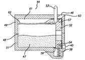
- FIG. 3is a side sectional view of the a build material cartridge dispenser of FIG. 2 showing the solidifiable liquid build material in the build material feed cartridge;
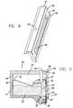
- FIG. 4is an isometric view of the front plate of the a build material cartridge dispenser of FIG. 2 with the dispensing channel through which the liquid build material is dispensed;
- FIG. 5is a diagrammatic cross-sectional illustration view of the build material cartridge dispenser dispensing liquid solidifiable build material through the dispensing channel and recovering unused liquid build material in a collection chamber via the scraper;
- FIG. 6is a diagrammatic cross-sectional illustration view of the build material cartridge dispenser with the dispensing valving closed, thereby retaining the liquid solidifiable build material in the cartridge reservoir and the recovery valving open to direct recovered unused liquid build material into the collection chamber;
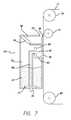
- FIG. 7is a diagrammatic illustration of a side elevational view of another embodiment of a disposable build material cartridge dispenser in contact with the endless belt as the build material intermediate transfer surface containing liquid build material in the reservoir chamber in preparation for delivering the liquid build material to the dispensing chamber by means of a pump;
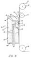
- FIG. 8is a diagrammatic illustration of a side elevational view of the disposable build material cartridge dispenser of FIG. 7 delivering liquid build material to the dispensing chamber by means of a pump, with excess liquid build material being returned via an overflow channel to the supply reservoir and unused liquid build material being removed from the endless belt surface, filtered and returned to the supply reservoir;
- FIG. 9is a diagrammatic illustration of a side elevational view of the disposable build material cartridge dispenser of FIG. 7 showing an embodiment utilizing a valve movable between an open and a closed position to control the flow of unused liquid build material through the scraper channel;
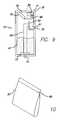
- FIG. 10is a front perspective view of a sealed liquid build material pouch container.
- FIG. 11is a diagrammatic illustration of a side elevational view of the disposable build material cartridge dispenser of FIG. 7 with a dispersing roller to remove air bubbles entrapped in the liquid build material that is metered onto the endless belt via the dispensing channel by pressing the liquid build material on the endless belt against a guide roller.
- Flexible transport solid imaging of the type disclosed hereininvolves the layer-by-layer build-up of articles from a solidifiable liquid build material that is a visible or UV radiation curable liquid photopolymer material.
- the liquid photopolymer materialis delivered by a radiation transparent flexible transport endless belt or reciprocatable sheet of film.
- Liquid photopolymer materialis applied to the endless belt or reciprocatable sheet of film from a disposable feed cartridge of the present invention employing an appropriate coating device such as a gravure wheel or fluid wedge that transfers the photopolymer build material to the intermediate transfer flexible transport surface to provide a fresh material to create new layers as the three-dimensional object is built.
- the photopolymer build materialis transferred from this flexible intermediate transfer surface via transfer means to a receiving substrate without entrapping air bubbles in the transferred layers.
- the photopolymer build materialis imaged by radiation projected from either a digital UV projector or a digital visible light projector and solidified layer-by-layer.
- the projectorincludes a spatial light modulator, such as a digital micro-mirror device (“DMD”) that selectively illuminates pixels for imaging. Visible light projection is a preferred approach.
- DMDdigital micro-mirror device
- Solid imaged partsare preferably built on an elevator platform that moves the build object or part into contact with the liquid photopolymer build material and, after exposure, out of contact with the liquid photopolymer build material as successive layers or laminae are formed during the building process.
- the build objectcan be built on structures known as supports rather than directly on the elevator platform. Supports are used for more complex three-dimensional objects being built that have unsupported or partially unsupported surfaces.
- digital light projectorsoptionally modified to have a shorter focal length, may be employed, such as those available from InFocus Corporation of Wilsonville, Oreg., BenQ America Corp. of Irvine, Calif. or Optima Corporation of Taiwan.
- the solidifiable liquid photopolymer build materialis delivered to the imaging area via a radiation transparent flexible build material carrier film, such as polypropylene or polycarbonate.
- the photopolymer build materialis applied in a thin layer to the flexible transport film in the embodiment shown in FIG. 1 .
- a flexible transport imaging system with covers (including cover 42 ) removedis indicated generally by the numeral 10 .
- Flexible transport imaging system 10has a radiation transparent build material intermediate transfer surface or carrier in the form of an endless belt 11 that is positioned about drive rollers 14 and 15 and follower or idler rollers 19 and 20 .
- a build material feed cartridge assemblyis indicated generally by the numeral 12 .
- the cartridge assembly 12 and the idler rollers 14 and 15are fixed in their relative positions.
- Belt 11is driven in the direction indicated by arrow 21 by electrical drive motors 22 and 24 that drive rollers 14 and 15 , respectively.
- the vertical distance between drive rollers 14 and 15is fixed, but the horizontal distance between the drive rollers 14 and 15 and idler rollers 19 and 20 is variable to control the tension in endless belt 11 .
- Idler rollers 19 and 20are rotatably mounted between vertical frame members 35 and 40 .
- a digital light projector(not shown) is the radiation source that projects an image with selected pixels for illumination onto a mirror system 41 of FIG. 1 below the upper run of endless belt 11 in the exposure of a cross-section of a three-dimensional object being formed on a support platform (not shown).
- the support platformis raised and lowered by a pair of stepper motors (also not shown) that ride up a threaded lead screw and guide rails on opposing sides of the imaging system 10 .
- the guide railsare held in place by guide rail anchor plates (all not shown) appropriately fastened to the system frame.
- a support platform assembly bar 31is fastened to each stepper motor. As best seen in FIG.
- support platform assembly bar 31extends through slot 32 in frame end plate 35 and a corresponding slot in an opposing end frame, both not shown, on the opposing side of the system 10 . This enables the support platform assembly bar 31 to move with the stepper motors to raise and lower the support platform. This brings the already formed cross-sectional layers into contact with the layer of resin or solidifiable liquid build material 47 that is deposited on endless belt 11 by a build material feed cartridge assembly 12 through a dispensing slit or channel, as will be described hereinafter.
- the build material feed cartridge assembly 12is a disposable cartridge dispenser that is an integral part of the flexible transport solid imaging system 10 .
- the disposable cartridge dispenserboth coats the belt 11 with solidifiable liquid build material and removes unused liquid build material from it.
- the cartridge dispenseralso contains a filtering device that cleans the removed unused liquid build material by separating out solid particulates before returning it to a supply reservoir.
- Cartridge dispenser 44includes a resin supply reservoir 48 of solidifiable liquid material 47 and a dispensing slit or channel 45 through which the solidifiable liquid build material 47 is applied to belt 11 .
- the dispensing channel 45is an elongated narrow opening and spans almost the entire width of the front of the disposable cartridge dispenser 44 , but it also could be a series of holes of any suitable geometric shape, such as a circle, square, rectangle or triangle, or a single opening of other suitable shape, such as an ellipsoid or rectangle, dependent upon the pattern and volume of liquid build material to be dispensed.
- Disposable cartridge dispenser 44contains a fluid flow control device in the form of a 3-position valve 52 that can be closed, partially open to remove material from the belt, or fully open to both coat and remove.
- FIG. 2is an isometric view of the assembled cartridge dispenser 44 . It consists of a top section 49 and a bottom section 51 which are secured together with a seal (not shown) between the sections. A hole 50 in the top section 49 is used to fill the cartridge dispenser 44 with solidifiable liquid build material 47 and is then sealed. Pins 43 are located on both ends of the cartridge and are used to removably secure the cartridge dispenser to the flexible transport solid imager.
- the dispensing channel 45 and scraper recovery channel 46are passageways to the liquid build material supply reservoir 48 , and are controlled by the internal slide valve 52 of FIG. 3 , which is actuated by plunger 53 .
- FIG. 3shows a cross-sectional side view of the solidifiable liquid build material cartridge dispenser 44 with valve 52 in the closed position. This is the default position of valve 52 . Valve 52 is in this position during shipping and storage of the cartridge dispenser, as well as when the flexible transport solid imager 10 is not in use.
- FIG. 3shows the top section 49 and bottom 50 section, as well as the dispensing channel 45 and scraper recovery channel 46 .
- the valve plunger 53actuates the slide valve 52 .
- the cartridge dispenser supply reservoir 48contains the solidifiable liquid build material 47 .
- FIG. 4shows an isometric view of the slide valve 52 with its actuation plunger 53 .
- Attached to valve 52are two forward facing attached sealing surfaces 54 , 55 for valve 52 , with the lower one 54 also acting as a seal to prevent the flow of build material through the dispensing channel 45 .
- the top forward facing seal 55along with top seal 57 , prevents the flow of liquid build material through the scraper recovery channel 46 .
- a supply channel 56passes through the front of the slide valve 52 .
- Top forward facing seal 55prevents liquid build material from rising upwardly into the scraper recovery channel 46 .
- the slide valve 52is in the closed position.
- the plunger 53also acts as an upper guide for the slide valve 52 due to its close fit through the hole in the top section 49 of cartridge dispenser 44 .
- spring 58biases the valve 52 towards its upper, closed position.
- Another spring 59provides a biasing force to keep the forward edge of slide valve in intimate contact with the inner face of the cartridge dispenser housing to effect a tight seal.
- the lower seal 54covers the dispensing channel 45
- the top seal 57covers the scraper recovery channel 46 while upper seal 55 sealingly seats against the interior housing of dispenser top section 49 .
- the solidifiable liquid build material 47is now prevented from flowing out through either of these channels and recovered unused liquid build material cannot enter via scraper recovery channel 46 .
- FIG. 5is a cross-sectional view of the cartridge dispenser 44 with the slide valve 52 in the fully open, or build position. Valve 52 is in this position during the building operation. In this position, the solidifiable liquid build material 47 is allowed to flow out of the dispensing channel 45 to coat the endless belt 11 , see briefly FIG. 1 , while simultaneously scraping the unused liquid build material 60 from the belt 11 just prior to the belt moving past the dispensing channel 45 where a fresh layer of solidifiable liquid build material 47 is applied to recoat the belt 11 of FIG. 1 for the next imaging cycle. The unused liquid build material 60 returns to the cartridge collection reservoir 61 where it is in fluid flow communication with the liquid build material supply reservoir 48 via a filter 62 .
- the unused liquid build material 60is strained through filter 62 and then returned to the liquid build material supply reservoir 48 for reuse.
- the unused liquid build material 60 on the belt 11is the portion of the photocurable material applied to the belt 11 which is not exposed and solidified by the image-wise radiation projected from the digital light projector during the imaging. Solid particulate matter is retained by the filter 62 and prevented from entering the supply reservoir 48 .
- the sharp scraping edge 63 adjacent the top and front of cartridge 44scrapes the surface of belt 11 as the belt travels over the edge 63 to remove the unused liquid build material.
- the plunger 53is pressed to its lowest position by an external actuator (not shown) that is part of the flexible transport imaging system 10 .
- the slide valve 52travels to its lowest position, compressing the spring 58 .
- the lower seal 54is now below the dispensing channel 45 , exposing the liquid build material 47 to the supply channel 56 in the valve 52 , and thereby allowing the solidifiable liquid build material 47 to flow to and out of the dispensing channel 45 .
- the upper seal 55opens the scraper recovery channel 46 which allows the unused liquid build material 60 to reenter the cartridge dispenser 44 , passing through the filter 62 and returning to the supply reservoir 48 for reuse.
- FIG. 6shows the disposable cartridge dispenser 44 with the valve 52 in an intermediate position, where the external actuator has pressed the plunger 53 only partially downward. This position is used for cleaning the belt 11 , but not for recoating it with fresh liquid build material 47 . This is useful to remove unused liquid build material 60 from the belt 11 at the end of a build, or when the flexible transport imaging system needs to stop or pause.
- the lower seal 54covers the dispensing channel 45 , preventing the flow of liquid build material 47 out of the cartridge dispenser 44 .
- the upper seal 57is now clear of the scraper recovery channel 46 which, as in the build position, collects the unused build material 60 by the action of the scraper edge 63 against the belt 11 , cleaning the belt. This also allows the unused liquid build material 60 to reenter the cartridge dispenser 44 via the scraper recovery channel 46 and collection reservoir 61 , pass through the filter 62 and return to the liquid build material supply reservoir 48 .
- FIG. 7shows an alternate and more preferred embodiment of a disposable cartridge dispenser 70 employed as the build material feed cartridge assembly 12 .
- FIG. 7is a diagrammatic illustration of the liquid build material dispenser cartridge, indicated generally by the numeral 70 , as well as the belt 11 , idler drive rollers 19 , 20 and auxiliary roller 71 .
- Inside the disposable cartridge dispenser 70is a supply of solidifiable liquid build material 47 .
- a pump 73such as an air operated silicone diaphragm pump or a peristaltic pump, is part of the cartridge dispenser 70 .
- An appropriate coupling 74connects to a controlled air supply (not shown) that is part of the flexible transport imaging system 10 .
- the cartridge dispenser 70also contains dispensing opening or channel 75 , a scraper edge 76 , a scraper recovery channel 77 , a collection reservoir 78 , and a material filter 79 .
- the dispensing channel 75is an elongated narrow opening. As described earlier, the dispensing channel 75 also could be a series of holes of any suitable geometric shape, such as a circle, square, rectangle or triangle, or a single opening of other suitable shape, such as an ellipsoid or rectangle, dependent upon the pattern and volume of liquid build material to be dispensed. The length and height of the opening formed by the dispensing channel 75 is dependent upon the volume of liquid build material to be dispensed over a desired area. Solidiflable liquid build material is pumped up to the chamber 81 and dispensing channel 75 through conduit 80 .
- the pump 73has been activated.
- Solidifiable liquid build material 47is pumped from the supply reservoir 72 , through a conduit 80 and into a chamber 81 that supplies the dispensing channel 75 and coats the belt 11 as the belt 11 is driven downwardly past the dispensing channel 75 .
- a dam 82At the top of chamber 81 is a dam 82 , above which is open to the interior of cartridge dispenser 70 and the solidifiable liquid build material supply reservoir 72 . Any liquid build material 47 above the level of this open topped dam 82 spills over and returns to the supply reservoir 72 .
- the level of solidifiable liquid build material 47 in the reservoiris replenished and through the pump 73 , a constant head pressure is maintained at the dispensing channel 75 , resulting in a fluid wedge and even coating of the belt 11 .
- At the bottom of chamber 81are one or more small drain holes 83 that allow solidifiable liquid build material 47 to constantly drain back into the supply reservoir 72 . In the event of a power failure, or any time the flexible transport imaging system stops, all of the liquid build material 47 in chamber 81 will drain back into the supply reservoir 72 , and the disposable cartridge dispenser 70 , or belt 11 , can be removed without spilling liquid build material.
- the pump 73is designed with sufficient capacity to keep the chamber 81 filled and overflow dam 82 during operation of the system even with the drain holes 83 , thereby achieving a constant pressure, fail-safe supply system.
- auxiliary roller 71that can be included to apply additional force to the junction between the belt 11 and scraper edge 76 .
- Auxiliary roller 71can be a silicone coated roller or other appropriate contact surface that directs the belt 11 into contact with the scraper edge 76 to achieve more complete cleaning than can be accomplished by belt tension alone.
- Auxiliary roller 71can be mounted for lateral movement to adjust the pressure exerted by the contact surface of the scraper edge 76 against the belt 11 as needed.
- the recovered unused liquid build materialseen as 84 in FIG. 8 , returns to cartridge dispenser 70 through scraper recovery channel 77 into collection reservoir 78 , from which it passes through the filter 79 enroute to returning to the supply reservoir 72 .
- a slide valve 85 loaded with one or more springs 86can be included in cartridge dispenser 70 to normally close off the scraper recovery channel 77 to prevent liquid build material from escaping when the cartridge dispenser 70 is not installed in the flexible transport imaging system.
- a passive mechanismsuch as a pin or lever (not shown) in the imaging system pushes the slide down, compressing the springs 86 and opening the slide valve 85 , shown in dotted lines, for use.
- a similar mechanismalso can be used to close off the dispensing channel 75 .
- a predetermined amount of solidifiable liquid build material 47may be dispensed into a plastic pouch, indicated generally by the numeral 87 in FIG. 10 .
- the pouch 87is sealed at seal joint 88 by heat or other appropriate means to make a leak proof package.
- FIG. 11shows a diagrammatic illustration of the cartridge dispenser 70 as previously described, but with the addition of a dispersing roller 89 downstream of the dispensing channel 75 .
- unused liquid build material 84is removed from the previously coated belt 11 by a scraper edge 76 and returned to the cartridge dispenser 70 via the scraper recovery channel 77 . During this scraping procedure, air is entrapped in the unused liquid build material 84 .
- the entrapped airis also circulated, so that as the solidifiable liquid build material 47 is metered onto the belt 11 by the dispensing channel 75 , the air in the form of bubbles cause voids and streaks in the coating of liquid build material coating on the belt 11 , resulting in voids in the final part formed by the layer-wise repetitive exposure of build material 47 .
- the dispersing roller 89is placed adjacent to the lower idler roller 20 in such a way that the belt 11 is driven between the rollers, with the dispersing roller 89 on the side of the belt 11 that is coated with the liquid build material 47 .
- the dispersing roller 89redistributes the liquid build material 47 on the belt 11 . In doing this, entrapped air is removed or expressed out of the liquid build material 47 , resulting in a void-free coating.
- the coating of solidifiable liquid build material 47is applied to the belt 11 at a metered rate by the dispensing channel 75 .
- the dispersing roller 89then redistributes the coating of solidifiable liquid build material 47 without air and, as an added advantage, aids in smoothing any inconsistencies in the coating thickness in both the longitudinal and latitudinal directions.
- the dispersing roller 89has an outer coating 90 made from a soft elastomeric material, such as silicone, and is influenced against the drive roller with a spring load (not shown).
- a soft elastomeric materialsuch as silicone
- a spring loadnot shown
- other suitable materials and appropriate biasing methodscan also be employed.
- the cartridge dispenser 70When the cartridge dispenser 70 is assembled, and a plastic pouch is utilized, the sealed plastic pouch 87 is placed into it. In this manner, the build material feed cartridge assembly is leak proof during shipping and storage.
- a slidable blade(not shown) or other appropriate device that has the ability to slice the plastic pouch 87 and release the solidifiable liquid build material 47 into the supply reservoir 72 .
- Attached to the bladeis ribbon (also not shown) or similar device that extends through the wall of the cartridge dispenser housing to the outside, preferably routed around and out of the upper surface of the cartridge dispenser.
- the ribbonis pulled by the installer, which in turn pulls the slidable blade, cutting the plastic and releasing the solidifiable liquid build material 47 into the supply reservoir 72 of the cartridge dispenser 70 .
- the cartridge dispenseris now ready to use.
- Drive rollers 14 and 15are rotatably mounted between vertical frame members 16 and 18 .
- Drive motors 22 and 24are mounted to vertical frame member 18 and are drivingly connected to drive rollers 14 and 15 .
- Drive roller vertical frame member 25is attached to the end of the drive motors.
- Belt tracking motor 26controls the tracking of belt 1 as it rotates about rollers 14 , 15 , 19 and 20 and faces in the opposite direction of drive motors 22 and 24 .
- a motor shaftextends through frame member 25 from motor 26 .
- a belt tracking control arm 29is attached to the end of the motor shaft.
- a tracking control arm frame member 30connects frame members 16 and 18 and includes a pivot attachment that is used to mount the drive roller carriage.
- a left edge belt tracking optical sensor 33 and a right edge belt tracking optical sensor 37are mounted to frame member 30 as seen in FIG. 1 .
- Drive roller 14 , idler roller 19 and endless belt 11are shown, along with vertical frame members 16 , 18 and 25 .
- a mounting arm 36is attached between a pivot attachment (not shown) on the drive roller carriage and the pivot 39 on the frame end plate 35 .
- the entire drive roller carriagemoves about pivot 39 that extends the distance between drive rollers 14 and 15 and idler rollers 19 and 20 , thereby putting tension on the endless belt 11 when an air cylinder plunger (not shown) is extended or reducing tension when it is retracted.
- the pivot point on the pivot attachmentis offset a small distance from the center of the pivot attachment.
- the air cylinder(not shown) mounts through end plate 35 so the cylinder plunger contacts the back of the pivot attachment on the back of tracking control arm frame member 30 . When the air cylinder is pressurized, its plunger exerts a force on the drive roller carriage via the pivot attachment. A desired tension can thus be maintained on the endless belt 11 .
- the tension in the belt 11controls the thickness of the solidifiable liquid build material 47 applied to the endless belt 11 as the belt 11 travels vertically downwardly across the dispensing slit or channel 45 or 75 in build material cartridge dispenser 44 or 70 , respectively, as seen in FIGS. 5 and 8 .
- the dispensing slit or channel in each embodimentsupplies liquid build material from the supply reservoir within cartridge dispenser 44 or 70 to the surface of the endless belt 11 .
- the cartridge dispenser 44 or 70can have a flat section above and below the dispensing channel 45 or 75 , respectively, and an arcuate section with large radius at the bottom to provide clearance for the build material 47 on the coated surface of belt 11 as the belt is driven in its path about rollers 14 , 15 , 19 and 20 .
- the bottom sectioncan be at an acute angle or a right angle to provide the required clearance.
- a fluid wedgedevelops at the bottom edge of the channel that applies an even coating onto the belt 11 via the fluid wedge effect so that the greater the tension in the belt 11 , the thinner is the coating.
- the coating thicknessis monitored by an appropriate sensor, such as a pattern recognition device. If the coating thickness is too thick, the air cylinder plunger will slowly be extended so as to increase the tension in belt 11 and decrease the fluid wedge, thereby making the coating thinner until the correct thickness coating is obtained. Alternately, if the coating is too thin, the plunger will be retracted, decreasing the belt 11 tension and thereby increasing the fluid wedge making the coating thicker until the desired thickness is obtained.
- the coating thicknesscan be controlled to 0.002 inches for faster imaging or to 0.001 inches for slower imaging.
- the air cylindercan exert between 10 to 20 pounds per square inch against the belt 11 to ensure the belt is taut about rollers 14 , 15 , 19 and 20 .
- Any other effective devicecan be used to exert pressure on the belt 11 , such as a solenoid valve, air cylinder, spring or other appropriate mechanical system.
- the fluid wedgecan be effectively created whether there is an angled bottom edge or a straight or rounded bottom surface to the dispensing channel 45 or 75 .
- the effectiveness of the fluid wedgeis a function of a number of factors including the viscosity of the solidifiable liquid build material 47 , the surface tension between the build material 47 and the belt 11 , the pressure head of liquid build material 47 in the disposable cartridge dispenser, the height of the opening of the dispensing channel 45 or 75 , the length of the flat sections above and below the dispensing channel, and the speed and tension of the belt 11 as it traverses about roller 14 , 15 , 19 , and 20 and past channel 50 .
- belt tracking motor 26exerts a rotational force on tracking control arm 29 .
- the control arm 29is attached to mounting arm 36 via a magnetic ball 38 or any other linkage suitable to pivot the drive roller carriage.
- the magnetic ball 38rests in a slot in the control arm 29 and a countersink in a mounting arm so that if motor 22 exerts a clockwise rotational force, the control arm 29 pushes the magnetic ball into the mounting arm, forcing the drive roller carriage away from the mounting arm.
- the motor 22exerts a counterclockwise rotational force
- the control armmoves away from the mounting arm and the magnetic force pulls the carriage toward the mount. This rotates the drive roller carriage about a pivot point 39 .
- the drive rollers 14 and 15rotate to steer the belt 11 .
- the belt 11steers to the left, and with a counter clockwise rotation, it steers to the right.
- Tracking sensors 33 and 37are placed apart at a distance so the width of the belt 11 just extends over the edges of the sensors 33 and 37 , respectively.
- Sensors 33 and 37are optical sensors that sense the presence of the belt 11 . In operation, as the belt 11 is being driven it will translate laterally until it uncovers one of the sensors 33 or 37 . The force on the tracking motor 22 will then be reversed and the belt 11 will translate until the other sensor is uncovered, and the process will reverse again. In this manner, the belt 11 is constantly moving laterally hack and forth across a small distance.
- An appropriate sub-pixel image displacement deviceis placed between the radiation light source and the target area on the belt 11 that is coated with the solidifiable liquid build material 47 .
- the exposure of the image cross-section by illuminating selected pixelscreates a solidified portion of the cross-section of the three-dimensional object being formed.
- the sub-pixel image displacement devicealternatively can be a mirror with the pixel shifting device being located outside of the runs of the endless belt 11 or it could combine both a mirror and pixel shifting device in a single element.
- Any suitable liquid build material capable of solidification in response to the application of an appropriate form of energy stimulationmay be employed in the practice of the present invention.
- Many liquid state chemicalsare known which can be induced to change to solid state polymer plastic by irradiation with UV radiation or visible light.
- a suitable visible light curable photopolymer that may be employed in the practice of the present inventionis shown in Table I below. This formulation exhibited excellent resolution and photospeed when utilized with a BenQ PB7220 projector. The parts created displayed outstanding green strength with balanced stiffness and toughness.
- data to build a three-dimensional objectis sent to the flexible transport solid imaging system from a CAD station (not shown) that converts the CAD data to a suitable digital layer data format and feeds it to a computer control system (also not shown) where the object data is manipulated to optimize the data via an algorithm to provide on/off instructions for the digital light projector.
- the solid imaging layer datais attained by the CAD data being processed by a slicing program to create cross-sectional data.
- An algorithmis then applied to the cross-sectional data by a suitable controller, such as a microprocessor or computer, to create the instructions for the digital light projector to illuminate selected pixels in the image within the boundary of the three-dimensional object in the cross-section being formed.
- An appropriate pixel shifting image displacement devicecan be employed to increase the resolution and edge smoothness of the cross-sections produced.
- Liquid build material 47is moved from the supply reservoir in the disposable liquid cartridge dispenser 44 and 70 to the dispensing channel and applied to the belt 11 .
- the support platformUpon completion of the imaging of a layer, the support platform is lowered. Since the cured image is now stuck to both the belt 11 and support platform, the belt 11 is pulled downward by a suitable technique with the platform until the part layer peels from the belt 11 . The belt 11 then returns back into its straightened form.
- the radiation transparent belt 11 carrying the liquid build material 47peels away from the exposed and solidified layer of build material forming the cross-section of the three-dimensional part being formed with no horizontal motion therebetween.
- the flexibility of the radiation transparent belt 11enables the separation to occur in a peeling type of action because the separation force is proportional to the width of the exposed area of the build material 47 as opposed to the total area of the exposed build material, as occurs in the case of an inflexible planar surface.
- Unused liquid build materialtravels on the belt 11 along its path of travel back past the disposable liquid build material dispenser 44 and 70 where the scraper edge 63 and 76 removes and directs the unused liquid build material 60 and 84 back into the cartridge collection reservoir 61 and 78 .
- the unused liquid build material 60 and 84passes into the solidifiable liquid build material reservoir 48 and 72 and is ready for reuse and dispensing onto the radiation transparent belt 11 .
- the substrate on which the part is built on the build support platformis chosen so that the part's bond to it is stronger than its bond to the belt 11 .
- the substrate materialshould be pervious, flexible, and easily attachable to the build support platform. It can be a fine sandpaper or similar material to give grip, but more preferably is a porous material, such as ground silicone, that allows any wet, uncured material to flow away from the part to keep the part as dry as possible.
- each new layerbonds to the cured build material of the layer below it.
- the beltis driven in direction of travel 21 to re-coat the belt 11 with the build material 47 .
- the belt 11will be driven approximately 12′′ to 18′′ to establish a consistent layer thickness of the build material.
- the build support platformis then raised into position. Since there is now a 0.001′′ thick slice of the part on the build support platform, the build support platform is raised into a position 0.001′′ lower than the previous one so that it is now the top of the part that is in intimate contact with the coating of build material 47 on the surface 51 of the belt 11 .
- this positioningis controlled by the stepper motors that raise and lower the build support platform in a manner that is very accurate in its movement and repeatable. If, for example, the stepper motors move the platform down 0.500′′ after each exposure, but move up only 0.499′′, they will always compensate for the 0.001′′ buildup per cycle. Now that the belt 11 has been re-coated and the build support platform is in position, the next slice of the part is projected, and the process continues until the part is complete.
- the build process and apparatuscan be inverted so that the build support platform moves from the top downwardly into contact with the endless belt by the stepper motors and the part is built in an inverted position.
Landscapes
- Chemical & Material Sciences (AREA)
- Engineering & Computer Science (AREA)
- Materials Engineering (AREA)
- Manufacturing & Machinery (AREA)
- Physics & Mathematics (AREA)
- Mechanical Engineering (AREA)
- Optics & Photonics (AREA)
Abstract
Description
| TABLE 1 | |||
| Units of | Weight | ||
| Weight | Percent | ||
| Acrylate-24 (from Sartomer Company) | % | |
| PRO 6817 (from Sartomer Company) | 4.8 | 23.02 |
| SR 833S (from Sartomer Company) | 3.5 | 16.79 |
| Ebecryl 83 (from UCB Chemicals Corp.) | 2.4 | 11.51 |
| PRO 6169 (from Sartomer Company) | 5.2 | 24.94 |
| SR 531 (from Sartomer Company) | 3.6 | 17.27 |
| Irgacure I-907 (From Ciba Specialty Chemicals, Inc.) | 0.75 | 3.60 |
| Irgacure 1-819 (From Ciba Specialty Chemicals, Inc.) | 0.6 | 2.88 |
| Total | 20.85 | 100.00 |
Additives can be incorporated into the formulation to promote release ability from the transparent transport means, such as silicone acrylate materials.
Claims (14)
Priority Applications (4)
| Application Number | Priority Date | Filing Date | Title |
|---|---|---|---|
| US11/416,811US7931460B2 (en) | 2006-05-03 | 2006-05-03 | Material delivery system for use in solid imaging |
| CN2007101011304ACN101067721B (en) | 2006-05-03 | 2007-04-29 | Material delivery system for use in solid imaging |
| EP07251804AEP1852244B1 (en) | 2006-05-03 | 2007-04-30 | Material delivery system for use in solid imaging |
| JP2007122294AJP4855998B2 (en) | 2006-05-03 | 2007-05-07 | Material supply device for use in solid-state imaging |
Applications Claiming Priority (1)
| Application Number | Priority Date | Filing Date | Title |
|---|---|---|---|
| US11/416,811US7931460B2 (en) | 2006-05-03 | 2006-05-03 | Material delivery system for use in solid imaging |
Publications (2)
| Publication Number | Publication Date |
|---|---|
| US20070257055A1 US20070257055A1 (en) | 2007-11-08 |
| US7931460B2true US7931460B2 (en) | 2011-04-26 |
Family
ID=38421629
Family Applications (1)
| Application Number | Title | Priority Date | Filing Date |
|---|---|---|---|
| US11/416,811Active2028-07-10US7931460B2 (en) | 2006-05-03 | 2006-05-03 | Material delivery system for use in solid imaging |
Country Status (4)
| Country | Link |
|---|---|
| US (1) | US7931460B2 (en) |
| EP (1) | EP1852244B1 (en) |
| JP (1) | JP4855998B2 (en) |
| CN (1) | CN101067721B (en) |
Cited By (20)
| Publication number | Priority date | Publication date | Assignee | Title |
|---|---|---|---|---|
| US9034237B2 (en) | 2012-09-25 | 2015-05-19 | 3D Systems, Inc. | Solid imaging systems, components thereof, and methods of solid imaging |
| USD733196S1 (en) | 2014-02-03 | 2015-06-30 | Wolf And Associates, Inc. | 3D printer enclosure |
| USD760306S1 (en) | 2015-03-20 | 2016-06-28 | Wolf & Associates, Inc. | 3D printer enclosure |
| US9688020B2 (en) | 2010-12-21 | 2017-06-27 | Stratasys Ltd. | Method and system for reuse of materials in additive manufacturing systems |
| US10195778B2 (en) | 2013-10-15 | 2019-02-05 | Wolf & Associates, Inc. | Three-dimensional printer systems and methods |
| US10792868B2 (en) | 2015-09-09 | 2020-10-06 | Carbon, Inc. | Method and apparatus for three-dimensional fabrication |
| US10994480B2 (en) | 2016-06-08 | 2021-05-04 | Wolf & Associates, Inc. | Three-dimensional printer systems and methods |
| US11731367B2 (en) | 2021-06-23 | 2023-08-22 | General Electric Company | Drive system for additive manufacturing |
| US11813799B2 (en) | 2021-09-01 | 2023-11-14 | General Electric Company | Control systems and methods for additive manufacturing |
| US11826950B2 (en) | 2021-07-09 | 2023-11-28 | General Electric Company | Resin management system for additive manufacturing |
| US11951679B2 (en) | 2021-06-16 | 2024-04-09 | General Electric Company | Additive manufacturing system |
| US11958249B2 (en) | 2021-06-24 | 2024-04-16 | General Electric Company | Reclamation system for additive manufacturing |
| US11958250B2 (en) | 2021-06-24 | 2024-04-16 | General Electric Company | Reclamation system for additive manufacturing |
| US12285908B2 (en) | 2020-11-20 | 2025-04-29 | General Electric Company | Foil interaction device for additive manufacturing |
| US12296535B2 (en) | 2021-08-24 | 2025-05-13 | General Electric Company | Attachment structure for additive manufacturing |
| WO2025155855A1 (en) | 2024-01-17 | 2025-07-24 | 3D Systems, Inc. | Systems, methods, and compositions for additive manufacturing |
| US12370741B2 (en) | 2021-08-13 | 2025-07-29 | General Electric Company | Material deposition assembly for additive manufacturing |
| US12403654B2 (en) | 2022-09-30 | 2025-09-02 | General Electric Company | Systems and methods for additive manufacturing |
| US12409604B2 (en) | 2022-03-23 | 2025-09-09 | General Electric Company | Systems and methods for additive manufacturing |
| US12434436B2 (en) | 2021-02-26 | 2025-10-07 | General Electric Company | Accumalator assembly for additive manufacturing |
Families Citing this family (50)
| Publication number | Priority date | Publication date | Assignee | Title |
|---|---|---|---|---|
| DE102004022606A1 (en)* | 2004-05-07 | 2005-12-15 | Envisiontec Gmbh | Method for producing a three-dimensional object with improved separation of hardened material layers from a building level |
| DE102004022961B4 (en)* | 2004-05-10 | 2008-11-20 | Envisiontec Gmbh | Method for producing a three-dimensional object with resolution improvement by means of pixel shift |
| WO2005110722A1 (en) | 2004-05-10 | 2005-11-24 | Envisiontec Gmbh | Method for producing a three-dimensional object with resolution enhancement by means of pixel shift |
| DE102006019963B4 (en) | 2006-04-28 | 2023-12-07 | Envisiontec Gmbh | Device and method for producing a three-dimensional object by layer-by-layer solidifying a material that can be solidified under the influence of electromagnetic radiation using mask exposure |
| DE102006019964C5 (en) | 2006-04-28 | 2021-08-26 | Envisiontec Gmbh | Device and method for producing a three-dimensional object by means of mask exposure |
| US7467939B2 (en)* | 2006-05-03 | 2008-12-23 | 3D Systems, Inc. | Material delivery tension and tracking system for use in solid imaging |
| US7636610B2 (en) | 2006-07-19 | 2009-12-22 | Envisiontec Gmbh | Method and device for producing a three-dimensional object, and computer and data carrier useful therefor |
| US7892474B2 (en) | 2006-11-15 | 2011-02-22 | Envisiontec Gmbh | Continuous generative process for producing a three-dimensional object |
| US7771183B2 (en)* | 2007-01-17 | 2010-08-10 | 3D Systems, Inc. | Solid imaging system with removal of excess uncured build material |
| US8003039B2 (en) | 2007-01-17 | 2011-08-23 | 3D Systems, Inc. | Method for tilting solid image build platform for reducing air entrainment and for build release |
| US20080170112A1 (en)* | 2007-01-17 | 2008-07-17 | Hull Charles W | Build pad, solid image build, and method for building build supports |
| US8105066B2 (en)* | 2007-01-17 | 2012-01-31 | 3D Systems, Inc. | Cartridge for solid imaging apparatus and method |
| US7706910B2 (en)* | 2007-01-17 | 2010-04-27 | 3D Systems, Inc. | Imager assembly and method for solid imaging |
| US7614866B2 (en)* | 2007-01-17 | 2009-11-10 | 3D Systems, Inc. | Solid imaging apparatus and method |
| US7731887B2 (en)* | 2007-01-17 | 2010-06-08 | 3D Systems, Inc. | Method for removing excess uncured build material in solid imaging |
| US8221671B2 (en)* | 2007-01-17 | 2012-07-17 | 3D Systems, Inc. | Imager and method for consistent repeatable alignment in a solid imaging apparatus |
| US20080181977A1 (en)* | 2007-01-17 | 2008-07-31 | Sperry Charles R | Brush assembly for removal of excess uncured build material |
| US20080226346A1 (en)* | 2007-01-17 | 2008-09-18 | 3D Systems, Inc. | Inkjet Solid Imaging System and Method for Solid Imaging |
| WO2008103985A2 (en)* | 2007-02-23 | 2008-08-28 | The Exone Company, Llc | Replaceable build box for three dimensional printer |
| ATE553910T1 (en) | 2007-07-04 | 2012-05-15 | Envisiontec Gmbh | METHOD AND DEVICE FOR PRODUCING A THREE-DIMENSIONAL OBJECT |
| EP2052693B2 (en)* | 2007-10-26 | 2021-02-17 | Envisiontec GmbH | Process and freeform fabrication system for producing a three-dimensional object |
| US8678805B2 (en) | 2008-12-22 | 2014-03-25 | Dsm Ip Assets Bv | System and method for layerwise production of a tangible object |
| US8777602B2 (en) | 2008-12-22 | 2014-07-15 | Nederlandse Organisatie Voor Tobgepast-Natuurwetenschappelijk Onderzoek TNO | Method and apparatus for layerwise production of a 3D object |
| KR20110104532A (en) | 2008-12-22 | 2011-09-22 | 네덜란제 오르가니자티에 포오르 토에게파스트-나투우르베텐샤펠리즈크 온데르조에크 테엔오 | Apparatus and method for producing layer units of three-dimensional objects |
| US8372330B2 (en) | 2009-10-19 | 2013-02-12 | Global Filtration Systems | Resin solidification substrate and assembly |
| DE202010015018U1 (en)* | 2010-11-07 | 2011-04-14 | Bohnet, Hans | Arrangement for producing structured substrates |
| US20130310507A1 (en)* | 2012-05-18 | 2013-11-21 | 3D Systems, Inc. | Adhesive for 3D Printing |
| ITVI20120183A1 (en)* | 2012-07-27 | 2014-01-28 | Dws Srl | CARTRIDGE FOR STEREOLITHOGRAPHIC MACHINE, STEREOLITHOGRAPHIC MACHINE INCLUDING SUCH CARTRIDGE AND METHOD OF PRODUCTION OF SUCH CARTRIDGE |
| WO2014141272A2 (en)* | 2013-03-14 | 2014-09-18 | Stratasys Ltd. | Enhanced resolution dlp projector apparatus and method of using same |
| US9573321B2 (en)* | 2013-03-14 | 2017-02-21 | Stratasys Ltd. | System and method for three-dimensional printing |
| US9527244B2 (en) | 2014-02-10 | 2016-12-27 | Global Filtration Systems | Apparatus and method for forming three-dimensional objects from solidifiable paste |
| JP6296901B2 (en)* | 2014-05-27 | 2018-03-20 | キヤノン株式会社 | Method for manufacturing three-dimensional object and apparatus for manufacturing the same |
| US20160009029A1 (en)* | 2014-07-11 | 2016-01-14 | Southern Methodist University | Methods and apparatus for multiple material spatially modulated extrusion-based additive manufacturing |
| CN112549529B (en) | 2014-07-13 | 2022-11-29 | 斯特拉塔西斯公司 | System for three-dimensional printing and method of manufacturing three-dimensional object |
| USD760719S1 (en) | 2014-10-20 | 2016-07-05 | Hand Held Products, Inc. | Scanner |
| CN108025489B (en)* | 2015-07-13 | 2020-07-28 | 斯特拉塔西斯公司 | Waste disposal for 3D printing |
| US20170072466A1 (en)* | 2015-09-16 | 2017-03-16 | Applied Materials, Inc. | Selectively openable support platen for additive manufacturing |
| CN108602249B (en)* | 2015-11-12 | 2021-03-02 | 克劳斯·斯塔德曼 | Stereolithography apparatus and drum mechanism |
| KR101773949B1 (en)* | 2016-07-20 | 2017-09-01 | 서울과학기술대학교 산학협력단 | 3D printer vat design for selective layered composite material and printing method |
| US10953598B2 (en)* | 2016-11-04 | 2021-03-23 | Continuous Composites Inc. | Additive manufacturing system having vibrating nozzle |
| US20180186072A1 (en)* | 2016-12-31 | 2018-07-05 | Abb Schweiz Ag | Method and system for manufacturing an article |
| US10737479B2 (en) | 2017-01-12 | 2020-08-11 | Global Filtration Systems | Method of making three-dimensional objects using both continuous and discontinuous solidification |
| US20180207863A1 (en)* | 2017-01-20 | 2018-07-26 | Southern Methodist University | Methods and apparatus for additive manufacturing using extrusion and curing and spatially-modulated multiple materials |
| WO2018194652A1 (en)* | 2017-04-21 | 2018-10-25 | Hewlett-Packard Development Company, L.P. | Three-dimensional printer |
| KR102291238B1 (en)* | 2017-07-28 | 2021-08-18 | 휴렛-팩커드 디벨롭먼트 컴퍼니, 엘.피. | 3D printer |
| CN111225758B (en)* | 2017-10-13 | 2022-04-29 | 株式会社Ihi | Powder supply device and three-dimensional lamination molding device |
| CN110103470A (en)* | 2018-02-01 | 2019-08-09 | 三纬国际立体列印科技股份有限公司 | Three-dimensional printing device |
| CH714727B1 (en)* | 2018-03-07 | 2022-07-15 | Coobx Ag | 3D printer disposable cartridge. |
| US12121964B2 (en) | 2018-11-07 | 2024-10-22 | James J. Myrick | Processes, compositions and systems for 2D and 3D printing |
| EP3702131B1 (en)* | 2019-02-28 | 2022-11-23 | Sirona Dental Systems GmbH | Material unit for an additive manufacturing device |
Citations (51)
| Publication number | Priority date | Publication date | Assignee | Title |
|---|---|---|---|---|
| US4752498A (en) | 1987-03-02 | 1988-06-21 | Fudim Efrem V | Method and apparatus for production of three-dimensional objects by photosolidification |
| US5014207A (en) | 1989-04-21 | 1991-05-07 | E. I. Du Pont De Nemours And Company | Solid imaging system |
| US5049901A (en) | 1990-07-02 | 1991-09-17 | Creo Products Inc. | Light modulator using large area light sources |
| US5094935A (en) | 1990-06-26 | 1992-03-10 | E. I. Dupont De Nemours And Company | Method and apparatus for fabricating three dimensional objects from photoformed precursor sheets |
| US5096530A (en) | 1990-06-28 | 1992-03-17 | 3D Systems, Inc. | Resin film recoating method and apparatus |
| US5122441A (en) | 1990-10-29 | 1992-06-16 | E. I. Du Pont De Nemours And Company | Method for fabricating an integral three-dimensional object from layers of a photoformable composition |
| US5132723A (en) | 1991-09-05 | 1992-07-21 | Creo Products, Inc. | Method and apparatus for exposure control in light valves |
| US5134962A (en)* | 1989-09-29 | 1992-08-04 | Hitachi, Ltd. | Spin coating apparatus |
| US5143817A (en) | 1989-12-22 | 1992-09-01 | E. I. Du Pont De Nemours And Company | Solid imaging system |
| US5158858A (en) | 1990-07-05 | 1992-10-27 | E. I. Du Pont De Nemours And Company | Solid imaging system using differential tension elastomeric film |
| US5171490A (en) | 1988-11-29 | 1992-12-15 | Fudim Efrem V | Method and apparatus for production of three-dimensional objects by irradiation of photopolymers |
| US5192559A (en) | 1990-09-27 | 1993-03-09 | 3D Systems, Inc. | Apparatus for building three-dimensional objects with sheets |
| US5236812A (en) | 1989-12-29 | 1993-08-17 | E. I. Du Pont De Nemours And Company | Solid imaging method and apparatus |
| US5247180A (en) | 1991-12-30 | 1993-09-21 | Texas Instruments Incorporated | Stereolithographic apparatus and method of use |
| US5306446A (en) | 1992-07-10 | 1994-04-26 | Howe Robert J | Apparatus with roller and for irradiation of photopolymers |
| US5429908A (en) | 1993-04-12 | 1995-07-04 | E. I. Du Pont De Nemours And Company | Exposure method for reducing distortion in models produced through solid imaging by forming a non-continuous image of a pattern which is then imaged to form a continuous hardened image of the pattern |
| US5447822A (en) | 1989-09-28 | 1995-09-05 | 3D Systems, Inc. | Apparatus and related method for forming a substantially flat stereolithographic working surface |
| US5474719A (en) | 1991-02-14 | 1995-12-12 | E. I. Du Pont De Nemours And Company | Method for forming solid objects utilizing viscosity reducible compositions |
| US5650260A (en) | 1993-10-14 | 1997-07-22 | Teijin Seiki Co., Ltd. | Method and apparatus for fabricating three-dimensional object |
| US6051179A (en) | 1997-03-19 | 2000-04-18 | Replicator Systems, Inc. | Apparatus and method for production of three-dimensional models by spatial light modulator |
| US6066285A (en) | 1997-12-12 | 2000-05-23 | University Of Florida | Solid freeform fabrication using power deposition |
| US6120404A (en) | 1998-09-09 | 2000-09-19 | Davis-Standard Corporation | Belt tensioner |
| US6174156B1 (en) | 1990-03-01 | 2001-01-16 | Dsm N.V. | Solid imaging apparatus and method with coating station |
| US6206672B1 (en) | 1994-03-31 | 2001-03-27 | Edward P. Grenda | Apparatus of fabricating 3 dimensional objects by means of electrophotography, ionography or a similar process |
| DE19957370A1 (en) | 1999-11-29 | 2001-06-13 | Carl Johannes Fruth | Method and device for coating a substrate |
| US6305769B1 (en)* | 1995-09-27 | 2001-10-23 | 3D Systems, Inc. | Selective deposition modeling system and method |
| US6391245B1 (en) | 1999-04-13 | 2002-05-21 | Eom Technologies, L.L.C. | Method for creating three-dimensional objects by cross-sectional lithography |
| US20020145213A1 (en) | 2001-04-10 | 2002-10-10 | Junhai Liu | Layer manufacturing of a multi-material or multi-color 3-D object using electrostatic imaging and lamination |
| DE10119817A1 (en) | 2001-04-23 | 2002-10-24 | Envision Technologies Gmbh | Separation layer between a flat baseplate and layers of cured polymer formed during fabrication of three-dimensional objects comprises a low adhesion film or a gel |
| US20020155189A1 (en)* | 2001-04-20 | 2002-10-24 | Envision Technologies Gmbh, | Apparatus for manufacturing a three-dimensional object |
| US6500378B1 (en) | 2000-07-13 | 2002-12-31 | Eom Technologies, L.L.C. | Method and apparatus for creating three-dimensional objects by cross-sectional lithography |
| US20030021823A1 (en) | 2001-06-27 | 2003-01-30 | Rudiger Landers | Coated polymer material, its use and process for its production |
| US6547552B1 (en) | 2000-02-08 | 2003-04-15 | Efrem V. Fudim | Fabrication of three-dimensional objects by irradiation of radiation-curable materials |
| US6641772B2 (en) | 1999-05-18 | 2003-11-04 | Creo Srl | Method of forming objects from thermosensitive composition |
| US6665048B2 (en) | 2002-01-22 | 2003-12-16 | Creo Inc. | Method for imaging a continuously moving object |
| DE10256672A1 (en) | 2002-12-04 | 2004-06-17 | Envisiontec Gmbh | Process and device to separate stereolithographic hardened material layers from a contact surface successively photopolymerizes fluid layers and performs controlled separation |
| US20040173946A1 (en) | 2003-03-07 | 2004-09-09 | Rolf Pfeifer | Process for quality control for a powder based layer building up process |
| US6792327B1 (en) | 1999-08-19 | 2004-09-14 | Bae Systems Plc | Stereolithographic method for combining components of varying densities |
| US6824714B1 (en) | 1999-08-20 | 2004-11-30 | Eos Gmbh Electro Optical Systems | Device and method for generative production of a three-dimensional object |
| US20050017393A1 (en) | 2003-07-23 | 2005-01-27 | 3D Systems, Inc. | Accumulation, control and accounting of fluid by-product from a solid deposition modeling process |
| EP1274559B1 (en) | 2000-04-17 | 2005-02-23 | Envisiontec GmbH | Device and method for the production of three-dimensional objects |
| US20050062815A1 (en)* | 2003-07-10 | 2005-03-24 | Fuji Xerox Co., Ltd. | Ink supplying apparatus and recording apparatus |
| US20050248061A1 (en) | 2004-05-07 | 2005-11-10 | Alexandr Shkolnik | Process for the production of a three-dimensional object with an improved separation of hardened material layers from a construction plane |
| US20050248062A1 (en) | 2004-05-10 | 2005-11-10 | Alexandr Shkolnik | Process for the production of a three-dimensional object with resolution improvement by "pixel-shift" |
| US6965364B1 (en) | 1999-09-17 | 2005-11-15 | Basys Print GmbH Systeme fuer die Drueckindustrie | Device and method for compensating non-uniformities in imaging systems |
| US7090484B2 (en) | 1999-04-27 | 2006-08-15 | Teijin Seiki Co., Ltd. | Stereolithographic apparatus and method for manufacturing three-dimensional object with photohardenable resin |
| US7128866B1 (en) | 1998-10-12 | 2006-10-31 | Dicon A/S | Rapid prototyping apparatus and method of rapid prototyping |
| US20060249884A1 (en) | 2005-05-03 | 2006-11-09 | 3D Systems, Inc. | Bubble-free cross-sections for use in solid imaging |
| US7158849B2 (en) | 2004-10-28 | 2007-01-02 | National Cheng Kung University | Method for rapid prototyping by using linear light as sources |
| US7261542B2 (en) | 2004-03-18 | 2007-08-28 | Desktop Factory, Inc. | Apparatus for three dimensional printing using image layers |
| US20070259066A1 (en) | 2006-05-03 | 2007-11-08 | 3D Systems, Inc. | Material delivery tension and tracking system for use in solid imaging |
Family Cites Families (4)
| Publication number | Priority date | Publication date | Assignee | Title |
|---|---|---|---|---|
| AU4971396A (en)* | 1995-02-01 | 1996-08-21 | 3D Systems, Inc. | Rapid recoating of three-dimensional objects formed on a cross-sectional basis |
| US6270335B2 (en)* | 1995-09-27 | 2001-08-07 | 3D Systems, Inc. | Selective deposition modeling method and apparatus for forming three-dimensional objects and supports |
| CN1262883C (en)* | 2000-07-17 | 2006-07-05 | 得克萨斯州大学系统董事会 | Method and system of automatic fluid dispensing for imprint lithography processes |
| US8672045B2 (en) | 2006-06-01 | 2014-03-18 | Whitney Projects Llc | Fire suppression systems and methods |
- 2006
- 2006-05-03USUS11/416,811patent/US7931460B2/enactiveActive
- 2007
- 2007-04-29CNCN2007101011304Apatent/CN101067721B/enactiveActive
- 2007-04-30EPEP07251804Apatent/EP1852244B1/enactiveActive
- 2007-05-07JPJP2007122294Apatent/JP4855998B2/enactiveActive
Patent Citations (67)
| Publication number | Priority date | Publication date | Assignee | Title |
|---|---|---|---|---|
| US4752498A (en) | 1987-03-02 | 1988-06-21 | Fudim Efrem V | Method and apparatus for production of three-dimensional objects by photosolidification |
| US5171490A (en) | 1988-11-29 | 1992-12-15 | Fudim Efrem V | Method and apparatus for production of three-dimensional objects by irradiation of photopolymers |
| US5014207A (en) | 1989-04-21 | 1991-05-07 | E. I. Du Pont De Nemours And Company | Solid imaging system |
| US5447822A (en) | 1989-09-28 | 1995-09-05 | 3D Systems, Inc. | Apparatus and related method for forming a substantially flat stereolithographic working surface |
| US5134962A (en)* | 1989-09-29 | 1992-08-04 | Hitachi, Ltd. | Spin coating apparatus |
| US5143817A (en) | 1989-12-22 | 1992-09-01 | E. I. Du Pont De Nemours And Company | Solid imaging system |
| US5236812A (en) | 1989-12-29 | 1993-08-17 | E. I. Du Pont De Nemours And Company | Solid imaging method and apparatus |
| US6174156B1 (en) | 1990-03-01 | 2001-01-16 | Dsm N.V. | Solid imaging apparatus and method with coating station |
| US6733267B2 (en) | 1990-03-01 | 2004-05-11 | Dsm Desotech, Inc. | Solid imaging apparatus and method with coating station |
| US5094935A (en) | 1990-06-26 | 1992-03-10 | E. I. Dupont De Nemours And Company | Method and apparatus for fabricating three dimensional objects from photoformed precursor sheets |
| US5096530A (en) | 1990-06-28 | 1992-03-17 | 3D Systems, Inc. | Resin film recoating method and apparatus |
| US5049901A (en) | 1990-07-02 | 1991-09-17 | Creo Products Inc. | Light modulator using large area light sources |
| US5529473A (en) | 1990-07-05 | 1996-06-25 | E. I. Du Pont De Nemours And Company | Solid imaging system using differential tension elastomerc film |
| US5158858A (en) | 1990-07-05 | 1992-10-27 | E. I. Du Pont De Nemours And Company | Solid imaging system using differential tension elastomeric film |
| US5192559A (en) | 1990-09-27 | 1993-03-09 | 3D Systems, Inc. | Apparatus for building three-dimensional objects with sheets |
| US5391072A (en) | 1990-10-29 | 1995-02-21 | E. I. Du Pont De Nemours And Company | Solid imaging apparatus having a semi-permeable film |
| US5122441A (en) | 1990-10-29 | 1992-06-16 | E. I. Du Pont De Nemours And Company | Method for fabricating an integral three-dimensional object from layers of a photoformable composition |
| US5474719A (en) | 1991-02-14 | 1995-12-12 | E. I. Du Pont De Nemours And Company | Method for forming solid objects utilizing viscosity reducible compositions |
| US5132723A (en) | 1991-09-05 | 1992-07-21 | Creo Products, Inc. | Method and apparatus for exposure control in light valves |
| US5247180A (en) | 1991-12-30 | 1993-09-21 | Texas Instruments Incorporated | Stereolithographic apparatus and method of use |
| JPH0639928A (en) | 1991-12-30 | 1994-02-15 | Texas Instr Inc <Ti> | Stereo-lithographic device and its use |
| EP0676275B1 (en) | 1991-12-30 | 2000-07-05 | Texas Instruments Incorporated | Stereolithographic exposure head |
| EP0549993B1 (en) | 1991-12-30 | 1997-03-26 | Texas Instruments Incorporated | Stereolithographic apparatus and method of forming a model |
| US5306446A (en) | 1992-07-10 | 1994-04-26 | Howe Robert J | Apparatus with roller and for irradiation of photopolymers |
| US5429908A (en) | 1993-04-12 | 1995-07-04 | E. I. Du Pont De Nemours And Company | Exposure method for reducing distortion in models produced through solid imaging by forming a non-continuous image of a pattern which is then imaged to form a continuous hardened image of the pattern |
| US5650260A (en) | 1993-10-14 | 1997-07-22 | Teijin Seiki Co., Ltd. | Method and apparatus for fabricating three-dimensional object |
| US6206672B1 (en) | 1994-03-31 | 2001-03-27 | Edward P. Grenda | Apparatus of fabricating 3 dimensional objects by means of electrophotography, ionography or a similar process |
| US6305769B1 (en)* | 1995-09-27 | 2001-10-23 | 3D Systems, Inc. | Selective deposition modeling system and method |
| US6051179A (en) | 1997-03-19 | 2000-04-18 | Replicator Systems, Inc. | Apparatus and method for production of three-dimensional models by spatial light modulator |
| US6066285A (en) | 1997-12-12 | 2000-05-23 | University Of Florida | Solid freeform fabrication using power deposition |
| US6120404A (en) | 1998-09-09 | 2000-09-19 | Davis-Standard Corporation | Belt tensioner |
| US7128866B1 (en) | 1998-10-12 | 2006-10-31 | Dicon A/S | Rapid prototyping apparatus and method of rapid prototyping |
| US6391245B1 (en) | 1999-04-13 | 2002-05-21 | Eom Technologies, L.L.C. | Method for creating three-dimensional objects by cross-sectional lithography |
| US7090484B2 (en) | 1999-04-27 | 2006-08-15 | Teijin Seiki Co., Ltd. | Stereolithographic apparatus and method for manufacturing three-dimensional object with photohardenable resin |
| US6641772B2 (en) | 1999-05-18 | 2003-11-04 | Creo Srl | Method of forming objects from thermosensitive composition |
| US6792327B1 (en) | 1999-08-19 | 2004-09-14 | Bae Systems Plc | Stereolithographic method for combining components of varying densities |
| US6824714B1 (en) | 1999-08-20 | 2004-11-30 | Eos Gmbh Electro Optical Systems | Device and method for generative production of a three-dimensional object |
| US6965364B1 (en) | 1999-09-17 | 2005-11-15 | Basys Print GmbH Systeme fuer die Drueckindustrie | Device and method for compensating non-uniformities in imaging systems |
| DE19957370A1 (en) | 1999-11-29 | 2001-06-13 | Carl Johannes Fruth | Method and device for coating a substrate |
| US6547552B1 (en) | 2000-02-08 | 2003-04-15 | Efrem V. Fudim | Fabrication of three-dimensional objects by irradiation of radiation-curable materials |
| EP1274559B1 (en) | 2000-04-17 | 2005-02-23 | Envisiontec GmbH | Device and method for the production of three-dimensional objects |
| US6942830B2 (en) | 2000-04-17 | 2005-09-13 | Envisiontec Gmbh | Device and method for the production of three-dimensional objects |
| US6500378B1 (en) | 2000-07-13 | 2002-12-31 | Eom Technologies, L.L.C. | Method and apparatus for creating three-dimensional objects by cross-sectional lithography |
| US20020145213A1 (en) | 2001-04-10 | 2002-10-10 | Junhai Liu | Layer manufacturing of a multi-material or multi-color 3-D object using electrostatic imaging and lamination |
| US7052263B2 (en) | 2001-04-20 | 2006-05-30 | Envisiontec Gmbh | Apparatus for manufacturing a three-dimensional object |
| US20020155189A1 (en)* | 2001-04-20 | 2002-10-24 | Envision Technologies Gmbh, | Apparatus for manufacturing a three-dimensional object |
| EP1250997B1 (en) | 2001-04-20 | 2005-11-30 | Envisiontec GmbH | Manufacturing device for three-dimensional object |
| US7195472B2 (en) | 2001-04-23 | 2007-03-27 | Envisiontec Gmbh | Apparatus and method for the non-destructive separation of hardened material layers from a flat construction plane |
| DE10119817A1 (en) | 2001-04-23 | 2002-10-24 | Envision Technologies Gmbh | Separation layer between a flat baseplate and layers of cured polymer formed during fabrication of three-dimensional objects comprises a low adhesion film or a gel |
| EP1439051A2 (en) | 2001-04-23 | 2004-07-21 | Envisiontec GmbH | Apparatus and process for the non-destructive separation of a layer of cured material from a flat support |
| US20020153640A1 (en) | 2001-04-23 | 2002-10-24 | Envision Technologies Gmbh | Apparatus and method for the non-destructive separation of hardened material layers from a flat construction plane |
| US20070063389A1 (en) | 2001-04-23 | 2007-03-22 | Envisiontec Gmbh | Apparatus and method for the non-destructive separation of hardened material layers from a flat construction plane |
| EP1439052A2 (en) | 2001-04-23 | 2004-07-21 | Envisiontec GmbH | Apparatus and process for the non-destructive separation of a cured material from a plane working support |
| JP2002370286A (en) | 2001-04-23 | 2002-12-24 | Envision Technologies Gmbh | Apparatus and method for separating material layer |
| EP1253002A1 (en) | 2001-04-23 | 2002-10-30 | Envision Technologies GmbH | Device and process for the non-destructive release of a product made of hardened layers from a plate platform |
| US20030021823A1 (en) | 2001-06-27 | 2003-01-30 | Rudiger Landers | Coated polymer material, its use and process for its production |
| US6665048B2 (en) | 2002-01-22 | 2003-12-16 | Creo Inc. | Method for imaging a continuously moving object |
| DE10256672A1 (en) | 2002-12-04 | 2004-06-17 | Envisiontec Gmbh | Process and device to separate stereolithographic hardened material layers from a contact surface successively photopolymerizes fluid layers and performs controlled separation |
| US20040173946A1 (en) | 2003-03-07 | 2004-09-09 | Rolf Pfeifer | Process for quality control for a powder based layer building up process |
| US20050062815A1 (en)* | 2003-07-10 | 2005-03-24 | Fuji Xerox Co., Ltd. | Ink supplying apparatus and recording apparatus |
| US20050017393A1 (en) | 2003-07-23 | 2005-01-27 | 3D Systems, Inc. | Accumulation, control and accounting of fluid by-product from a solid deposition modeling process |
| US7261542B2 (en) | 2004-03-18 | 2007-08-28 | Desktop Factory, Inc. | Apparatus for three dimensional printing using image layers |
| US20050248061A1 (en) | 2004-05-07 | 2005-11-10 | Alexandr Shkolnik | Process for the production of a three-dimensional object with an improved separation of hardened material layers from a construction plane |
| US20050248062A1 (en) | 2004-05-10 | 2005-11-10 | Alexandr Shkolnik | Process for the production of a three-dimensional object with resolution improvement by "pixel-shift" |
| US7158849B2 (en) | 2004-10-28 | 2007-01-02 | National Cheng Kung University | Method for rapid prototyping by using linear light as sources |
| US20060249884A1 (en) | 2005-05-03 | 2006-11-09 | 3D Systems, Inc. | Bubble-free cross-sections for use in solid imaging |
| US20070259066A1 (en) | 2006-05-03 | 2007-11-08 | 3D Systems, Inc. | Material delivery tension and tracking system for use in solid imaging |
Non-Patent Citations (12)
| Title |
|---|
| English Translation of DE 19957370A1, Jun. 13, 2001. |
| European Search Report for App. No. EP 07251804 dated Jun. 29, 2009. |
| U.S. Appl. No. 11/856,172, filed Sep. 17, 2007. |
| U.S. Appl. No. 11/856,183, filed Sep. 17, 2007. |
| U.S. Appl. No. 11/856,209, filed Sep. 17, 2007. |
| U.S. Appl. No. 11/856,225, filed Sep. 17, 2007. |
| U.S. Appl. No. 11/856,241, filed Sep. 17, 2007. |
| U.S. Appl. No. 11/856,270, filed Sep. 17, 2007. |
| U.S. Appl. No. 11/856,378, filed Sep. 17, 2007. |
| U.S. Appl. No. 11/856,405, filed Sep. 17, 2007. |
| U.S. Appl. No. 11/856,428, filed Sep. 17, 2007. |
| U.S. Appl. No. 11/856,455, filed Sep. 17, 2007. |
Cited By (24)
| Publication number | Priority date | Publication date | Assignee | Title |
|---|---|---|---|---|
| US9688020B2 (en) | 2010-12-21 | 2017-06-27 | Stratasys Ltd. | Method and system for reuse of materials in additive manufacturing systems |
| US11001004B2 (en) | 2010-12-21 | 2021-05-11 | Stratasys Ltd. | Method and system for disposal of waste materials in additive manufacturing systems |
| US10245784B2 (en) | 2010-12-21 | 2019-04-02 | Stratasys Ltd. | Method and system for reuse of materials in additive manufacturing systems |
| US9034237B2 (en) | 2012-09-25 | 2015-05-19 | 3D Systems, Inc. | Solid imaging systems, components thereof, and methods of solid imaging |
| US10195778B2 (en) | 2013-10-15 | 2019-02-05 | Wolf & Associates, Inc. | Three-dimensional printer systems and methods |
| USD733196S1 (en) | 2014-02-03 | 2015-06-30 | Wolf And Associates, Inc. | 3D printer enclosure |
| USD776727S1 (en) | 2015-03-20 | 2017-01-17 | Wolf & Associates, Inc. | 3D printer enclosure |
| USD760306S1 (en) | 2015-03-20 | 2016-06-28 | Wolf & Associates, Inc. | 3D printer enclosure |
| US10792868B2 (en) | 2015-09-09 | 2020-10-06 | Carbon, Inc. | Method and apparatus for three-dimensional fabrication |
| US10994480B2 (en) | 2016-06-08 | 2021-05-04 | Wolf & Associates, Inc. | Three-dimensional printer systems and methods |
| US12285908B2 (en) | 2020-11-20 | 2025-04-29 | General Electric Company | Foil interaction device for additive manufacturing |
| US12434436B2 (en) | 2021-02-26 | 2025-10-07 | General Electric Company | Accumalator assembly for additive manufacturing |
| US11951679B2 (en) | 2021-06-16 | 2024-04-09 | General Electric Company | Additive manufacturing system |
| US11731367B2 (en) | 2021-06-23 | 2023-08-22 | General Electric Company | Drive system for additive manufacturing |
| US11958249B2 (en) | 2021-06-24 | 2024-04-16 | General Electric Company | Reclamation system for additive manufacturing |
| US11958250B2 (en) | 2021-06-24 | 2024-04-16 | General Electric Company | Reclamation system for additive manufacturing |
| US11826950B2 (en) | 2021-07-09 | 2023-11-28 | General Electric Company | Resin management system for additive manufacturing |
| US12390986B2 (en) | 2021-07-09 | 2025-08-19 | General Electric Company | Resin management system for additive manufacturing |
| US12370741B2 (en) | 2021-08-13 | 2025-07-29 | General Electric Company | Material deposition assembly for additive manufacturing |
| US12296535B2 (en) | 2021-08-24 | 2025-05-13 | General Electric Company | Attachment structure for additive manufacturing |
| US11813799B2 (en) | 2021-09-01 | 2023-11-14 | General Electric Company | Control systems and methods for additive manufacturing |
| US12409604B2 (en) | 2022-03-23 | 2025-09-09 | General Electric Company | Systems and methods for additive manufacturing |
| US12403654B2 (en) | 2022-09-30 | 2025-09-02 | General Electric Company | Systems and methods for additive manufacturing |
| WO2025155855A1 (en) | 2024-01-17 | 2025-07-24 | 3D Systems, Inc. | Systems, methods, and compositions for additive manufacturing |
Also Published As
| Publication number | Publication date |
|---|---|
| EP1852244A3 (en) | 2009-08-05 |
| EP1852244B1 (en) | 2011-10-05 |
| EP1852244A2 (en) | 2007-11-07 |
| CN101067721B (en) | 2012-02-08 |
| US20070257055A1 (en) | 2007-11-08 |
| JP2007296854A (en) | 2007-11-15 |
| JP4855998B2 (en) | 2012-01-18 |
| CN101067721A (en) | 2007-11-07 |
Similar Documents
| Publication | Publication Date | Title |
|---|---|---|
| US7931460B2 (en) | Material delivery system for use in solid imaging | |
| US7467939B2 (en) | Material delivery tension and tracking system for use in solid imaging | |
| EP1710625B1 (en) | Improved edge smoothness with low resolution projected images for use in solid imaging | |
| US7074029B2 (en) | Accumulation, control and accounting of fluid by-product from a solid deposition modeling process | |
| US10220565B2 (en) | Process and device for producing a three-dimensional object | |
| CN1046355C (en) | Stereoscopic imaging apparatus and method with coating station | |
| US20060249884A1 (en) | Bubble-free cross-sections for use in solid imaging | |
| EP2748676B1 (en) | Three-dimensional imaging systems, components thereof, and methods of three-dimensional imaging | |
| EP1946911A2 (en) | Cartridge for solid imaging apparatus and method | |
| EP1946907A2 (en) | Solid imaging apparatus and method | |
| US20170291355A1 (en) | Apparatus for 3D printing | |
| KR102222469B1 (en) | 3D Printer | |
| KR102542807B1 (en) | 3D printer | |
| KR102288941B1 (en) | stereo lithography 3D printer by using multi-resin coated film | |
| JP3571123B2 (en) | 3D modeling equipment | |
| CN116551979A (en) | Photo-curing 3D printing device and printing method | |
| DE19535967A1 (en) | Method of making a print web with a graphic image | |
| KR102288942B1 (en) | stereo lithography 3D printer by using resin coated film | |
| KR20240076779A (en) | Stereolithography printing system and method |
Legal Events
| Date | Code | Title | Description |
|---|---|---|---|
| AS | Assignment | Owner name:3D SYSTEMS, INC., CALIFORNIA Free format text:ASSIGNMENT OF ASSIGNORS INTEREST;ASSIGNORS:SCOTT, SUZANNE M.;SPERRY, CHARLES R.;MCNAMARA, DENNIS R.;REEL/FRAME:017859/0906 Effective date:20060501 | |
| STCF | Information on status: patent grant | Free format text:PATENTED CASE | |
| FPAY | Fee payment | Year of fee payment:4 | |
| MAFP | Maintenance fee payment | Free format text:PAYMENT OF MAINTENANCE FEE, 8TH YEAR, LARGE ENTITY (ORIGINAL EVENT CODE: M1552); ENTITY STATUS OF PATENT OWNER: LARGE ENTITY Year of fee payment:8 | |
| AS | Assignment | Owner name:HSBC BANK USA, NATIONAL ASSOCIATION, AS ADMINISTRA Free format text:SECURITY INTEREST;ASSIGNOR:3D SYSTEMS, INC.;REEL/FRAME:048456/0017 Effective date:20190227 Owner name:HSBC BANK USA, NATIONAL ASSOCIATION, AS ADMINISTRATIVE AGENT, NEW YORK Free format text:SECURITY INTEREST;ASSIGNOR:3D SYSTEMS, INC.;REEL/FRAME:048456/0017 Effective date:20190227 | |
| AS | Assignment | Owner name:3D SYSTEMS, INC., SOUTH CAROLINA Free format text:RELEASE BY SECURED PARTY;ASSIGNOR:HSBC BANK USA, NATIONAL ASSOCIATION;REEL/FRAME:057651/0374 Effective date:20210824 | |
| MAFP | Maintenance fee payment | Free format text:PAYMENT OF MAINTENANCE FEE, 12TH YEAR, LARGE ENTITY (ORIGINAL EVENT CODE: M1553); ENTITY STATUS OF PATENT OWNER: LARGE ENTITY Year of fee payment:12 |