US7928976B2 - Telestrator system - Google Patents
Telestrator systemDownload PDFInfo
- Publication number
- US7928976B2 US7928976B2US12/791,090US79109010AUS7928976B2US 7928976 B2US7928976 B2US 7928976B2US 79109010 AUS79109010 AUS 79109010AUS 7928976 B2US7928976 B2US 7928976B2
- Authority
- US
- United States
- Prior art keywords
- video
- graphic
- blending
- camera
- event
- Prior art date
- Legal status (The legal status is an assumption and is not a legal conclusion. Google has not performed a legal analysis and makes no representation as to the accuracy of the status listed.)
- Expired - Lifetime
Links
Images


Classifications
- H—ELECTRICITY
- H04—ELECTRIC COMMUNICATION TECHNIQUE
- H04N—PICTORIAL COMMUNICATION, e.g. TELEVISION
- H04N5/00—Details of television systems
- H04N5/222—Studio circuitry; Studio devices; Studio equipment
- H04N5/262—Studio circuits, e.g. for mixing, switching-over, change of character of image, other special effects ; Cameras specially adapted for the electronic generation of special effects
- H04N5/272—Means for inserting a foreground image in a background image, i.e. inlay, outlay
- H—ELECTRICITY
- H04—ELECTRIC COMMUNICATION TECHNIQUE
- H04N—PICTORIAL COMMUNICATION, e.g. TELEVISION
- H04N5/00—Details of television systems
- H04N5/222—Studio circuitry; Studio devices; Studio equipment
- H04N5/262—Studio circuits, e.g. for mixing, switching-over, change of character of image, other special effects ; Cameras specially adapted for the electronic generation of special effects
Definitions
- the present inventionis directed to a system for annotating video or still images.
- broadcastershave deployed a varied repertoire of technologies to highlight to viewers these exciting events. For example, broadcasters have started adding graphical enhancements to the video of the sporting events. Examples of graphic enhancements have included highlighting moving objects, highlighting portions of a playing field (e.g. first down line), adding virtual advertisements and adding of other graphics to the video of the event.
- telestrator systemis a system that allows an operator to draw on live or stored video. Examples of drawing on the live or stored video include the operator drawing lines, circles or other shapes, or symbols. While the operator draws the lines, the operator will discuss events, objects or people significant to the drawing.
- One example of a successful use of telestrator systemsis during the broadcast of American football games. An announcer may draw on an image to show a player out of position, a loose ball, a player offsides, etc.
- Various telestrator systemsallow the broadcaster to control the width, color, texture and shadowing of any drawing. Additionally, some systems allow for the inclusion of automatic shapes and animated icons with the video.
- Prior art telestrator systemstypically include a video monitor with a touch screen or digitizing table. In communication with both the touch screen and the monitor is a processor. The processor receives input from the touch screen and is responsible for adding to the video whatever is drawn by the user.
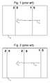
- FIG. 1depicts a frame of video 10 .
- Frame 10shows a portion of an American football field including the 15 yard line and the 20 yard line.
- the operator of the prior art telestrator systemhas drawn an arrow 12 to indicate where a player was running, direction of movement, etc. If the camera providing the video were to pan so that the camera points to a different portion of the football field, the portion of the football field in the video would change but the position of arrow 12 in the frame would not.
- FIG. 2shows a second frame 14 from the prior art telestrator system. Frame 14 differs from frame 10 because the camera has panned to show the 25 yard line. Although the location of the portions of the field have moved between frame 10 and frame 14 , the position of arrow 12 remains in the exact same position in frames 10 and 14 .
- arrow 12If the operator originally was drawing arrow 12 to show the path a player ran on the field, when frame 14 is depicted arrow 12 will no longer show the actual path. That is, in frame 10 arrow 12 shows a path across the 15 yard line stopping just before the 20 yard line. On the other hand, in frame 14 arrow 12 shows a path not crossing the 15 yard line, but rather crossing the 20 yard line. Thus, arrow 12 is no longer an accurate representation of what the operator intended to draw.
- a further enhancement that could be made to prior art telestrator systemsis to improve the quality of the illustration. For example, an operator may have sloppy penmanship and, thus, the lines or shapes drawn could appear too sloppy or not pleasing to the viewer. Alternatively, when prior art telestrator operators draw over video, whatever they draw tends to be placed on top of and obscuring the players or objects. Therefore, there is a need to improve the prior art telestrator systems.
- the present inventionis directed to an improved telestrator system that allows a broadcaster or other operator to annotate video during or after an event.
- an announceror other user
- the present inventioncan use the present invention to draw over the video of the event to highlight one or more actions, features, etc.
- the present inventionwhen the user draws over the video it appears that the user is drawing on the actual field or location of the event.
- Other embodiments of the present inventioninclude technology for smoothing out whatever the user draws to make it look more pleasing to the eye.
- the present inventionincludes drawing in a manner that does not obscure or hide persons or objects.
- the systemreceives points drawn by a user. These points are used to create a smooth curve and the curve is transformed to three dimensional locations on the field or surface. These three dimensional locations are then transformed back to two dimensional positions in future video frames so that whatever is drawn will appear to be drawn on the field even if the camera moves or a different camera is used.
- the systemincludes a touch screen and a display in communication with one or more processors.
- the processor(s)receive data representing the user's drawing from the touch screen, smooth the data, transform the data to three dimensional locations, transform the data back to two dimensional locations for future frames or fields, and blend the user's drawing with the video.
- the blendingcan be performed with a video processor, a keyer or another video modification device.
- the processor(s)use data from camera sensors.
- These camera sensorsare connected to or in communication with various video cameras at the event. Suitable camera sensors include optical shaft encoders, inclinometers and fibre optic gyros, as well as monitoring electrical outputs of the camera lens (2 ⁇ Extender, focus, zoom). Data from the camera sensors is used to determine the camera viewpoint (position in space, orientation and field of view). This data can be used to create transformation matrices to transform positions between three dimensional real space and two dimensional video coordinate systems.
- the present inventionis accomplished using a combination of both hardware and software.
- the software used for the present inventionis stored on one or more processor readable storage media including hard disk drives, CD-ROMs, optical disks, floppy disks, RAM, ROM or other suitable storage devices.
- processor readable storage mediaincluding hard disk drives, CD-ROMs, optical disks, floppy disks, RAM, ROM or other suitable storage devices.
- some or all of the softwarecan be replaced by dedicated hardware including custom integrated circuits, gate arrays, FPGAs, PLDs, and special purpose computers. Additionally, much of the hardware discussed below can be replaced by additional software on general purpose or special video computers.
- FIGS. 1 and 2show video frames that result from the use of prior art telestrator systems.
- FIGS. 3 and 4depict video frames that result from use of the present invention telestrator system.
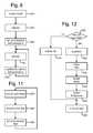
- FIG. 5is a block diagram of one exemplar set of hardware used to implement the present invention.
- FIG. 6is a flow chart describing a process that uses the current invention.
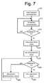
- FIG. 7is a flow chart describing the setting of a filter pass band.
- FIG. 8is a flow chart describing a portion of the operation of the present invention.
- FIG. 9is a flow chart describing the process of smoothing a curve.
- FIG. 10is a flow chart that explains one embodiment of the process of determining alpha values for pixels in a video.
- FIG. 11is a flow chart describing a portion of the operation of the present invention.
- FIG. 12is a flow chart describing the steps for enhancing a field of video.
- the present inventioncan be used to enhance a video representation of an event.
- the example discussed in this present applicationis the broadcast of an American football game.
- the present inventionapplies equally to other sporting events and other non-sporting events.
- the present inventioncan be used to enhance live video, stored video or still images.
- One exemplar enhancementis the blending of one or more graphics with the video.
- a graphicincludes drawings or illustrations, highlights, logos, shapes, etc. Examples of drawings include curves, shapes, text and anything that can be drawn by hand or otherwise.
- a curveincludes curved lines and straight lines.
- Videomeans the analog or digital signal depicting (or used to produce) moving images.
- Blendingmeans combining at least a first image or video with at least a second image of video such that the result includes all or part of that first image or video and all or part of the second image or video.
- One example of how images are blendedincludes using a keyer to key one video or image over another video or image.
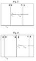
- FIG. 3shows a video frame 16 which is broadcast as a result of using the present invention. The operator had drawn an arrow 12 to show the path of a player or object on the playing field.
- FIG. 3shows a video frame 16 which is broadcast as a result of using the present invention. The operator had drawn an arrow 12 to show the path of a player or object on the playing field.
- FIG. 4shows a video frame 18 which is also the result of using the present invention.
- FIG. 4shows arrow 12 at a different position in frame 18 than in frame 16 . That is because after the user had drawn arrow 12 and it was depicted in frame 16 , the camera panned down the playing field. Instead of being pointed between the 20 and 15 yard lines, the camera is now pointed directly at the 20 yard line and, thus, the 25 yard line is now visible. Because the field moved within the camera's field of view, the location of arrow 12 also moved within the camera's field of view. Arrow 12 now appears to be drawn directly on the playing field as opposed to on the television monitor. As the field moves on the video screen, arrow 12 will also move.
- the blending of the graphics from the user of the telestrator systemmust take into account occlusions. That is, if a player steps on top of the area where the graphic is, the graphic should not be drawn over the player. The player should appear to be stepping or standing in front of the graphic. Similarly, there may be portions of the surface or field which should not be drawn over by the user's graphic. For example, the broadcaster may decide that the announcer's drawing should not appear to obscure any objects (such as a football) or markings on the field (e.g. the numbers painted on the field).
- FIG. 5is a block diagram of the hardware components that comprise one embodiment of the present invention.
- the user interface for the operator of the present inventionincludes a display 102 and touch screen 104 mounted on display 102 .
- the displayis a flat panel display and the touch screen is manufactured from Elo TouchSystems, Inc. (www.elotouch.com).
- the output of touch screen 104is sent to telestration processor 108 .
- telestration processor 108sends a video signal to video format converter 106 .
- the output of video format converter 106is communicated to display 102 .
- video format converter 106converts the video signal of telestration processor 108 from VGA format to NTSC format.
- a user of the systemcan use a finger on touch screen 104 to draw a graphic (e.g. shape or curve). Information about what is being drawn is sent to telestration processor 108 . The resulting blend of the graphic with the video is sent back to display 102 . In another embodiment, display 102 would receive the actual broadcast.
- a graphice.g. shape or curve
- Telestration processor 108also receives the program video. At a given event, a broadcaster typically uses multiple cameras. The producer or director of the event will typically choose one camera for broadcast. The program video is the video from the camera chosen for broadcast. Telestration processor 108 may also receive video from other sources (e.g. replay decks, other cameras, etc.) for offline work. Telestration processor 108 also receives data from gatherer 110 . In one embodiment, gatherer 110 is a computer. In another embodiment, gatherer 110 can be dedicated hardware. Gatherer 110 receives time code from VITC (Vertical Interval Time Code) 112 , camera sensor data from the various instrumented cameras (line 114 ), and key data from a key data processor 116 .
- VITCVery Interval Time Code
- Each of the cameras used with the present inventionincludes a number of camera sensors that measure data (camera sensor data) to determine the field of view of the camera.
- FIG. 5shows an example of camera 130 with camera sensors 132 .
- the camera sensorscould include any or all of the following: optical shaft encoders, fibre optic gyros, inclinometers, and reading voltages from the lens (e.g. 2 ⁇ Extender, focus, zoom). Other camera sensors can also be used.
- Data from camera sensors 132is sent to gatherer 110 .
- the camera sensor data for a given camerais transmitted to a production studio from the camera location via the camera's audio channel.
- the production studioincludes hardware to demodulate the audio channel and send the camera sensor data to gatherer 110 .
- the production studiois in a truck at the event.
- the video from camera 130is sent to camera control unit 134 , which controls various video and optical parameters for camera 130 .
- the output of camera control unit 134is sent to VITC inserter 136 which adds a time code and unique camera identifier into the vertical blanking interval of the video from camera 130 .
- the present inventioncan be operated using one or more instrumented cameras. In one embodiment, the present invention is operated with six cameras instrumented as shown in FIG. 1 . Each camera would have its own CCU and its own VITC inserter. Each camera's VITC inserter is synchronized with VITC 112 . In alternative embodiments, the present invention can be used with fixed, non-instrumented cameras. In another alternative, the present invention can be used with non-instrumented cameras that are not fixed, in combination with image recognition.
- Broadcast cameras used according to the present inventionare typically part of a camera assembly that includes a tripod base, a camera head interface (also called a tripod head interface) mounted on the tripod base, a camera head (also called a tripod head) mounted on the camera head interface, a camera mounted on the camera head, and a lens mounted on the camera.
- the tripod baseis the standard tripod known in the art.
- the camera headcan be a standard camera head known in the art, for example, a Vector 70 from Vinten, Inc.
- the Vector 70allows the camera to tilt and pan.
- optical shaft encoderscan be attached at the pan axis and tilt axis to measure the rotation of the camera about the pan axis and tilt axis.
- An example of an optical shaft encoderis the CP-850 Series from Computer Optical Products, 9305 Eton Avenue, Chatsworth, Calif. 91311.
- the pan shaft encoderis mounted in the camera head interface.
- One or more inclinometerscan be mounted on the camera head interface to measure attitude of the stationary portion of the camera assembly. Thus, if the camera assembly is on an angle, is kicked, or otherwise changes, that change in attitude will be detected.
- a suitable inclinometeruses liquid between a pair of plates, and measures change of capacitance. Another example is an electrolyte varying the conductance between two conductors.
- a suitable inclinometerindicates an absolute angle.
- the inclinometercan indicate angles up to ⁇ 1°, ⁇ 1.5° or ⁇ 6°. Other suitable ranges can also be used.
- a suitable inclinometeris the Ceramic Tilt Sensor SH50054 from Spectron, 595 Old Willets Path, Hauppaug, N.Y. 11788, (516) 582-5600.
- Other suitable inclinometerscan also be used with the present invention.
- the systemwill include two inclinometers. A first inclinometer would be mounted on a first surface of the camera head interface. A second inclinometer would be mounted on a second surface of the camera head interface. The first surface is ideally orthogonal to the second surface. Both inclinometers would be connected to an electronics board for receiving the data and packaging it with the other sensors. The electronics board is part of the camera head interface.
- One or more gyroscan be mounted on the camera lens to measure high frequency vibrations and mechanical compliance between the moving portion of the camera assembly and the stationary portion of the camera assembly.
- the systemincludes two gyros mounted on a block.
- the blockitself is mounted on the lens of the camera.
- the first gyrois mounted on a first surface of the block and the second gyro is mounted on the second surface of the block.
- the first surfaceis ideally orthogonal to the second surface.
- the two gyroscan be mounted on the tripod or the camera head interface. While the encoders discussed above measure angles relative to a fixed base, the gyro measures absolute angular rate information that is not relative to any part of the camera assembly.
- the gyrosare fibre optic gyros.
- An example of a suitable fibre optic gyrois the E-Core 2000 Series Fibre Optic Gyro manufactured and sold by KVH Industries, Inc., 50 Enterprise Center, Middleton Road, Rhode Island 02842.
- Other gyrosthat could also be used include a ring laser, mechanical gyro, tuning fork, spinning disk gyro, semiconductor gyro, etc. Integrating the output of the gyro will produce an angle delta indicating that the gyro was rotated by a certain angle.
- the fibre optic gyro discussed abovemeasures angular rate about a single axis.
- multi-directional gyroscan also be used.
- the systemcan use three or more gyros instead of two in order to measure pitch, roll and yaw.
- each camera sensor unit 132includes electronics in the camera head interface for receiving signals from the pan encoder, tilt encoder, two gyros, two inclinometers, 2 ⁇ Extender, lens focus and lens zoom. This data is sent to a processor which packages the data, synchronizes the data and encodes the data on the audio channel by modulating an audio carrier in order to send the data in the camera's microphone (or audio) channel to the television production studio. More information about using camera sensors can be found in U.S. patent application Ser. No. 09/160,534 filed Sep. 24, 1998, U.S. Pat. No. 5,912,700, both of which are incorporated herein by reference.
- Gatherer 110also receives information from key data processor 116 .
- key data processor 116 , telestration processor 108 and rendering processor 150are O2 workstations from Silicon Graphics. Other computers can also be used.
- Key data processor 116is used to provide information on which colors are included and excluded from being blended with the illustrations by the operator. More information on this will be discussed below.
- gatherer 110packages the key data, the sensor data and the time code into a set of information and sends that set of information to telestration processor 108 . Gatherer 110 can package other types of data as well.
- Telestration processor 108determines how the graphics drawn on touch screen 104 should be blended with the program video and sends that information to rendering processor 150 .
- Rendering processor 150takes charge of the actual blending of the graphics with the program video.
- rendering processor 150supplies two signals 170 and 172 to program keyer 152 and off-line keyer 154 .
- Signal 170is called alpha and signal 172 is called foreground.
- Program keyeralso receives an input from video delay 158 .
- Video delay 158receives the program video and delays it for a number of frames and transmits the delayed video to program keyer 152 and rendering processor 150 .
- the delayed program video sent to program keyer 152is called background.
- program keyer 152determines how much foreground and background to blend on a pixel by pixel basis. Program keyer 152 can blend from 100% foreground and 0% background to 0% foreground and 100% background.
- the alpha for a particular pixelcan range from 0% to 100% (or 0-1 or another similar range as per the specification of the keyer).
- the output of program keyer 152can be sent for broadcast, recording or both. During typical operation described below, the output of program keyer 152 is live video.
- Alpha 170 and foreground 172are also sent to off-line keyer 154 .
- the background signal received by off-line keyer 154is from video delay 160 .
- the delayed video from video delay 160is from a video storage device such as a tape player or other suitable storage device.
- the video input to delay 160is from a camera.
- the video input to delay 160is also sent to telestration processor 108 .
- the output of offline keyercan be used to produce replays, half time shows or highlights.
- the systemcan also include a kill switch which can be used by an operator to enable or disable the keying of the graphic. Additionally, a watch dog timer can be included to automatically disable the keying of the graphic if rendering processor 150 stops sending a periodic signal.
- the systemcould also include a data inserter for inserting non-video data into a television signal.
- Non-video datais information other than traditional data used by a television to draw the normal scan lines on a television display.
- An example of non-video datais data transmitted during the vertical blanking interval, which can be closed-caption data, statistics regarding the game, interactive queries or Internet addresses.
- the optional data insertercan receive the video signal from program keyer 152 and insert the non-video data into the vertical blanking interval of the television signal. The output of the data inserter would be broadcast, recorded or both.
- a data insertercan insert into the video signal instructions for a computer to enhance the video.
- a set-top boxwhich can read the instructions from the received signal and pass the information to the computer.
- the computercan use the instructions to blend the graphic with the video.
- a viewercan customize and control the enhancements using the viewer's personal computer.
- the set-top boxwill be capable of applying the enhancement.
- FIG. 6is a flow chart describing operation using the present invention.
- One embodiment of the present inventionincludes making the graphics drawn using touch screen 104 look like they were drawn on the actual field or surface. This requires transforming coordinates between two dimensional coordinate systems and three dimensional coordinate systems.
- One means for accomplishing such transformationincludes using a model of the surface being displayed on television.
- step 250the user of the system creates a mathematical model of the environment being displayed on the television. If the system is being used to add illustrations to a football field, then the environment would only include the football field and step 250 would include creating a model of the football field. If the user intends to add illustrations to other portions of the stadium, then the environment must include those other portions of the stadium as well.
- the model createdis a three dimensional model of the environment.
- the modelwould include a description of the surface of the football field. Most football fields are not flat surfaces, and include crown for drainage purposes. Additionally, many fields include other variations in the height (and possibly length and width) of the field due to errors and other abnormalities. Thus, the model will serve as a three dimensional representation of the surface of the field. If the environment includes portions of the stadium, then the model will include the relevant features of the stadium such as any retainer walls, the top of the stands and any other surface the user may want to add a graphic to.
- each data pointincludes x, y and z values. Any method can be used to obtain these x, y and z values.
- a suitable methodis to use a laser plane for z values and a laser range finder for x and y values, or other surveying devices.
- a coordinate systemis set up with the origin at the near corner of the left end zone, the y-axis along the width of the field (e.g. the back of the end zone), the x-axis is along the length of the field (e.g. the side line) and the z-axis extends vertically from the field.
- the operatorcan measure or use the yard markings on the field to determine the x and y coordinates for most points of interest on the field.
- the laser planecan be used to measure the corresponding z coordinate.
- the laser planeis utilized by placing the laser plane at the origin (or another point) and reading the laser image off a pole that is positioned at the point of interest.
- data samplesare taken for the back of both ends zones, both goal lines, both 20 yard lines and both 40 yard lines. For each yard line measured, measurement should at least be taken at each side line and then one or more points between the sidelines, including the middle of the field. Additional data points around the yard lines can also be measured. If the environment includes parts of the stadium, the laser plane, measuring tape or another measuring device can be used (as well as geometry) to determine data for other points in the environment.
- the data points measuredcan be used to create the model. That is, data points can be plotted and connected (symbolically).
- the systemis registered in step 252 .
- Registrationa technology known by those skilled in the art, is the process of defining how to interpret data from a sensor and/or to ascertain data variable for operation of the system.
- the sensors described aboveoutput data, for example, related to position and orientation. Since position and orientation are relative, the system needs a reference from which to determine position or orientation. Thus, in order to be able to use camera sensor data, the system needs to know how to interpret the data to make use of the information.
- registrationincludes pointing the instrumented cameras at known locations and solving for unknown variables used in transformation matrices. More detail of how to register the system can be found in any of the patent applications or patents incorporated by reference above or in U.S. Pat. No. 5,862,517 which is incorporated herein by reference.
- the operatorwill set up inclusions and exclusions.
- the graphiccan be added to the video without taking into account the contents of the video signal. There will be no accounting for occlusions; for example, a player or object in front of the surface on which the enhancement is intended to appear.
- the present inventioncan include inclusions and/or exclusions in order to account for occlusions and other object or markings.
- An inclusionis a color range for a pixel that can be enhanced using the present invention.
- An exclusionis a color range for a pixel that should not be enhanced using the present invention.
- the operatorcan set up one or more inclusions and/or one or more exclusions.
- the operatormay decide that a graphic can be drawn over green (grass) and brown (dirt). Additionally, the operator may want to set up the exclusion so that a line is not drawn over a specific color (e.g. team's uniforms). It is possible to allow drawing over one shade of green (grass) and not allow drawing over a second shade of green (team's shirt color).
- exclusionscan also include video frame pixel positions or real world locations that are not to be enhanced. The process of setting up inclusions and exclusions is performed using key data processor 116 .
- step 254 of FIG. 6includes sending an output from a camera to key data processor 116 .
- the camerawill be panned and tilted to point to the different areas of the field or stadium.
- the operatorcan view the output of the camera on a monitor and, using a pointing device (e.g. a mouse), select areas for inclusion (create an inclusion filter) or exclusion (create an exclusion filter).
- a pointing devicee.g. a mouse
- select areas for inclusioncreate an inclusion filter
- exclusioncreate an exclusion filter
- key data processor 116When setting up inclusions and exclusions, key data processor 116 first receives a set of pixels.
- the pixel set receivedis from the output of one of the cameras.
- a pixel setcan include selected pixels from an image of the playing field, selected pixels from an image of one of the teams' uniforms, or other images.
- the pixel setcan be received from a stored image.
- the operator of key data processor 116determines whether the pixel set is to be used for identifying exclusion pixels or identifying inclusion pixels. If it is determined that the pixel set has been received for establishing criteria for exclusion pixels, then key data processor 116 generates an exclusion filter. If it is determined that the pixel set has been received to establish criteria for inclusion pixels, then key data processor 116 generates an inclusion filter. Multiple inclusion filters and exclusion filters can be generated.
- key data processor 116generates inclusion filters and exclusion filters by generating a set of histograms characterizing the received sets of pixels.
- an inclusion filtermay include a Y histogram, a Cr histogram and a Cb histogram, all of which describe the inclusion filter in YCbCr format.
- the Y characteristic histogramhas a horizontal axis representing luminance values and a vertical axis representing the number of pixels in the received pixel set that corresponds to each of the luminance values.
- the Cr characteristic histogramhas a horizontal axis representing Cr values and a vertical axis representing the number of pixels in the received pixel set that corresponds to each of the Cr values.
- the Cb characteristic histogramhas a horizontal axis representing Cb values and a vertical axis representing the number of pixels in the received pixel set that corresponds to each of the Cb values.
- Each histogramhas a respective pass band that defines the Y, Cr, or Cb characteristics that a pixel must have to be an inclusion pixel. Accordingly, a pixel will be designated as an inclusion pixel when the filter is applied and the pixel has a Y characteristic value within the Y pass band, a Cr characteristic value within the Cr pass band, and a Cb characteristic value within the Cb pass band.
- Exclusion filterswork in a similar manner.
- FIG. 7illustrates a sequence of operation performed by key data processor 116 to determine a pass band for an inclusion filter histogram or an exclusion filter histogram.
- the steps of FIG. 7are performed for each of the three histograms.
- key data processor 116identifies the most frequently occurring value for the characteristic (Y, Cr, or Cb) represented by the histogram in step 270 .
- the characteristic valueis incremented in step 272 . It is then determined whether the number of pixels having the resulting characteristic value is within a predetermined percentage of the number of pixels having the most frequently occurring characteristic value in step 274 .
- the predetermined percentage employed in step 274is 10 percent for an inclusion filter and 50 percent for an exclusion filter.
- the characteristic valueis incremented in step 272 and a new comparison is performed. If it is determined that the number of pixels with the characteristic value is not above the predetermined percentage, then the maximum characteristic value for the pass band is set in step 276 to be equal to the last characteristic value with a number of pixels above the predetermined percentage.
- the characteristic valueis set to be equal to the characteristic value just below the most frequently occurring characteristic value in step 278 . It is then determined whether the number of pixels having the resulting characteristic value is above a predetermined percentage of the number of pixels having the most frequently occurring characteristic value in step 280 .
- the predetermined percentage employed in step 280is one percent for an inclusion filter and twenty five percent for an exclusion filter. In another embodiment of the present invention, the predetermined percentage employed in step 280 is 10 percent for an inclusion filter and 50 percent for an exclusion filter.
- the characteristic valueis decreased in step 280 and a new comparison is performed. If it is determined that the number of pixels with the characteristic value is not above the predetermined percentage, then the minimum characteristic value for the pass band is set in step 284 to equal the last characteristic value with a number of pixels above the predetermined percentage of the number of pixels representing the most frequently occurring characteristic value.
- an inclusion filter and exclusion filterhas been described with respect to forming a histogram, one of ordinary skill in the art will recognize that it is not necessary to actually form a graphical image of a histogram.
- a processorcould also maintain a table of data that reflects the Y, Cr, and Cb data.
- percentage thresholds identified aboveare not the only percentages that may be employed. Any number of percentages may be employed, depending upon the resolution that is desirable for the filter.
- Other methodscan be employed for generating inclusion filters and exclusion filters. For example, a color region or set of color regions can be selected for inclusion or exclusion using a chromacity diagram. More information on how to set up and use inclusions and exclusions is provided in U.S. patent application Ser. No. 09/160,534, filed Sep. 24, 1998, incorporated herein by reference.
- a color mapis created.
- the color mapis a database with a record for each possible color based on Y, Cr and Cb values. In an alternative embodiment, less than all of the possible colors are represented in the color map.
- the databasestores an alpha percentage.
- the stored alpha percentagecould be a number between zero and one hundred, zero and one, or another suitable range. Although the term percentage is used, the stored number need not be a number designating a fraction of one or a fraction of one hundred. The stored number need only designate an amount of blending. In one embodiment the stored alpha percentage is a number between 0 and 255.
- the operatorWhen the operator selects a pixel set for an inclusion or an exclusion, the operator is asked to provide a percentage between zero and one hundred percent. The number provided by the operator is converted to a scale of 0-255. The converted number is stored as the alpha percentage for each color described by the inclusion/exclusion filter (e.g. each color within the pass bands of the filter).
- a taper zoneis set up.
- the taper zoneincludes colors outside of but near the pass bands for a filter.
- One method for determining the colors in the taper zoneis to create an additional set of pass bands (in addition to the inclusion pass bands) in the same manner as described above, but use different percentages so that the pass bands are wider. Those colors in the new pass bands but not in the inclusion pass bands are in the taper zone.
- the colors in the taper zone closest to the inclusion pass bandsare given an alpha percentage equal to or slightly lower than the alpha percentage given to the colors in the inclusion/exclusion pass bands.
- the colors in the taper zone farthest from the inclusion pass bandsare given an alpha percentage equal to no blending.
- the colors in betweenare given an alpha percentage based on linear interpolation.
- An analogous methodis used for taper zones near exclusions. The alpha percentages for each color in the taper zones are stored in the color map.
- step 256shows step 258 which includes updating the exclusions and inclusions using key data processor 116 .
- step 258includes updating the exclusions and inclusions using key data processor 116 .
- lighting conditions, field conditions and weather conditionsmay change causing the colors to be included and excluded to change.
- the inclusions and exclusionscould be updated in step 258 .
- FIG. 6shows step 258 being performed after step 256 .
- steps 256 and 258are actually performed concurrently or otherwise overlapped in time. In one embodiment or appropriate situations where there are no changes in conditions, step 258 would be optional.
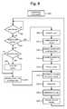
- FIG. 8describes the operations performed by telestration processor 108 .
- Step 300includes receiving and storing pixel coordinates from touch screen 104 . That is, as the user touches touch screen 104 with the user's finger (or a light pen or other suitable device), touch screen 104 outputs the coordinates of the pixel touched and sends the coordinates to telestration processor 108 . As the user continues to move the user's finger, more points are sent to telestration processor 108 . As telestration processor 108 receives those points, they are stored in memory, a hard disk or another storage medium. Step 300 is not depicted as being connected to any other steps because it is a process that is constantly being performed during the operation of the system.
- telestration processor 108waits for a new frame to start in step 302 .
- telestration processor 108determines whether it has received any new points from touch screen 104 since the last frame. If it has received new points, then in step 308 , telestration processor 108 smooths the curve represented by the points received from touch screen 104 . That is, the operator using a light pen, mouse, finger or other pointing device to draw may draw a line or curve that is filled with jagged edges otherwise not very pleasing to the eye. Step 308 includes smoothing that curve or line to a more pleasing shape.
- telestration processor 108creates a set of points to represent the smoothed curve.
- Step 310includes dividing up the curve between each control point into eight (or more) segments. The end points of each segment are the points created in step 310 .
- telestration processor 108identifies the correct set of sensor data.
- gatherer 110receives data from all of the camera sensors and package it into one set of data, to be sent to telestration processor 108 .
- each VITC insertere.g. VITC inserter 136
- telestration processor 108looks at the vertical blanking interval of the program video it is receiving and identifies the camera by the unique camera identifier. Gatherer 110 added a camera identifier to the sensor data for each of the individual cameras. Telestration processor 108 will match the camera identifier and time code from the program video to the camera identifier and time code of the appropriate camera sensor data. Thus, telestration processor 108 will use the camera sensor data from the camera providing the program video.
- the sensor data used to transform the graphicsmay be recently recorded or may be previously recorded (e.g. fifteen minutes previously, hours previously, etc.).
- video captured earlieris stored with its camera identifier and times codes.
- the stored camera identifier and times codescan be used to identify the appropriate stored camera sensor data. In this way, the invention can operate on stored video and stored sensor data after the event has taken place.
- each of the points identified in step 310are transformed from the two dimensional coordinate system of the touch screen to the three dimensional coordinate system of the football field (or other surface of the live event).
- Various means for converting points between coordinate systemsare known in the art.
- One example of doing such a transformationis to use transformation matrices.
- transformation matricesto convert between coordinate systems is well documented in the art.
- One of ordinary skill in the artwould know to insert the data from the camera sensors identified in step 312 into a set of transformation matrices and use those matrices. Examples of the use of transformation matrices can be found in U.S. Pat. Nos. 5,862,517, 5,912,700 and U.S. patent application Ser. No.
- Step 314includes transforming all of the points created in step 310 .
- telestration processor 108has a set of points in the three dimensional coordinate system of the football field (or surface) representing the curve drawn by the operator.
- the curveis thickened. That is, telestration processor 108 creates a set of quadrilaterals in three dimensional space. The centers of each of the adjacent sides of the quadrilaterals are the points that were transformed in step 314 .
- Step 316includes storing the vertices for each of these quadrilaterals. This set of vertices defines the thickened line in three dimensional space.
- telestration processor 108transforms all the curves to the current video frame (or field). That is, all of the vertices of the current curve just operated on in steps 308 - 316 are transformed to the two dimensional coordinate system for the current camera tallied for broadcast. Additionally, there may be other curves or graphics that may be drawn on the screen previously that have been stored in three dimensional space. These curves are also transformed in step 318 . The curves are transformed by transforming each of the vertices of the various quadrilaterals representing the curves. The quadrilateral vertices are transformed using transformation matrices.
- the systemtessellates the curves in step 320 .
- Tessellationinvolves breaking up the quadrilaterals if the cameras have zoomed in past a certain threshold.
- a thresholdis testing whether the sides of the quadrilaterals are more than 15 pixels. For a particular quadrilateral, if the threshold has been met then the quadrilateral is subdivided into small quadrilaterals.
- the systemwill divide the length and width (in pixels) of the quadrilaterals by 15, with the result being the number of sections the length or width must be broken up. In one alternative, the number of sections is rounded to the nearest power of two for convenience.
- telestration processor 108determines alphas for a subset of the pixels for the current video frame or field to be blended. These alphas will be used to derive the alpha signal 170 sent by rendering processor 150 to program keyer 152 and/or offline keyer 154 . In one embodiment, step 322 determines alpha values for each vertex of each quadrilateral after tessellation (step 320 ). After step 322 , telestration processor 108 adds the graphics to the program video and sends the enhanced program video to display 102 . This output sent to display 102 may not suitable for broadcast. The final broadcast video is provided by program keyer 152 . After determining the alphas in step 322 , telestration processor 108 sends the information to rendering processor 150 in step 324 and the system loops back to step 302 .
- telestration processor 108determines that it has not received any new points, then an inquiry is made (step 340 ) as to whether the user has finished drawing the curve.
- a pen-up eventis generated which signals that the user has finished drawing the curve or graphic.
- the methodloops to step 344 and the system will save the curve in three dimensional coordinates. That is, the points that were the result of step 316 are saved. If there was no pen-up event, the method loops to step 348 .
- telestration processor 108If telestration processor 108 is performing step 348 , it is assumed that no new curve data has been received and the system needs to redraw the existing curves onto the new frame (or field of video). In step 348 , telestration processor 108 identifies the correct sensor data (similar to step 312 ). After accessing the correct data in step 348 , telestration processor 108 loops to step 318 and continues the process from step 318 to draw the existing curves for the current field or frame of video. It is contemplated that the interface for the present invention could include an erase button which causes all curves currently being displayed to be erased and the system to be reset in that respect.
- FIG. 9is a flow chart describing more detail of step 308 of FIG. 8 , smoothing the curve of points received from touch screen 104 .
- the processreceives the pixel coordinates. These pixel coordinates have an X coordinate and a Y coordinate pertaining to the position on touch screen 104 .
- the coordinatesare added to a raw point list.
- the systemalso maintains a control point list.
- the systemdetermines whether there are any points on the control point list. If there are no points on the control point list, then the raw points just received in step 402 are added to the control point list in step 404 and the method loops back to step 402 .
- step 406it is determined that the control point list does include one or more control points, then the method loops to step 410 and telestration processor 108 determines whether the most recent point added to the raw point list in step 404 is a distance greater than a threshold from the last control point added to the control point list.
- a thresholdis ten pixels. If the distance between the most recent raw point and the last current point is not greater than the threshold, then the method loops back to step 402 . If the distance between the most recent raw point and the last control point is greater than the threshold, then the method loops to step 414 and the most recent raw point is added to the control point list.
- step 422If the number of control points in the control point list is exactly two points, then the method loops to step 422 and a line is drawn between these two points. After step 422 , the method loops back to step 402 . If in step 418 , there are more than two control points in the control point list, the method loops to step 426 , at which point the next to last control point is removed from the control point list. In step 430 , telestration processor 108 will fit a cubic Bezier spline through the control points. In step 434 , telestration processor 108 will find the removed control point that is farthest away from the curve. A removed control point is a point that was once on the control point list, but was subsequently removed from the control point list.
- telestration processor 108will determine whether distance from the curve to the removed control point found in step 434 is greater than a threshold (e.g. ten pixels). If the distance is not greater then the threshold, the method loops back to step 402 . If the distance is less than or equal to the threshold, then in step 440 that removed control point is added back to the control point list and the cubic Bezier spline is re-computed.
- a thresholde.g. ten pixels
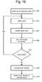
- FIG. 10illustrates a sequence of operations performed in one embodiment of the present invention for determining an alpha value for one of the vertices of a quadrilateral.
- a set of pixels in the program videois selected in step 560 .
- the set of pixels in the program videoinclude the pixel in the program video having the same coordinates as the vertex under consideration. Additionally, the set contains at least four pixels surrounding the pixel in the program video having the same coordinates as the vertex under consideration. In other embodiments, more or fewer than four additional pixels can be used. In one alternative, the four pixels are adjacent to the pixel in the program video having the same coordinates as the vertex under consideration.
- the four pixelsare a predefined distance away from the pixel in the program video having the same coordinates as the vertex under consideration.
- the predefined distancecan be selected from experimentation based on the desired effect.
- one of the pixels in the setis selected.
- the color of the pixelis used to access the color map. That is the Y, Cr and Cb values or characteristics for the pixel are used to access the appropriate alpha percentage in the color map described above.
- the alpha percentage accessed in the color mapis added to a counter.
- step 570a determination is made as to whether there are more pixels to be considered from the set of pixels. If there are more pixels to be considered, then a new pixel from the set is selected in step 562 . Otherwise, a key fraction is calculated in step 572 .
- the key fractionis calculated by dividing the counter value by the total number of pixels in the selected set of program pixels.
- the counter valueshould equal the sum of the alpha percentages for each pixel in the set. The key fraction, therefore, represents the average alpha percentage for the set. It is contemplated that other means can be employed to determine the key fraction.
- the alpha value for the vertexis determined in step 574 by multiplying the key fraction by a nominal alpha.
- the nominal alphais set in advance by the user to set the overall transparency or look of the graphic.
- a slider on a graphical user interfaceallows a user to see how changing the nominal alpha changes the keying. The above described process is repeated for each of the vertices.
- An alternative method for determining alphas and drawing graphicis described in U.S. patent application “System For Enhancing a Video Presentation of a Live Event,” Gloudemans, et al., Ser. No. 09/160,534, filed Sep. 24, 1998, incorporated herein by reference.
- FIG. 11is a flow chart which describes the operation of rendering processor 150 .
- rendering processor 150waits for the next frame to start.
- Rendering processor 150receives the program video from video delay 158 . By looking at the program video, rendering processor 150 determines when the next frame is starting.
- Rendering processor 150receives data from telestration processor 108 . This data includes the pixel coordinates of the polygons to be drawn, tessellations per quadrilateral (number of subdivides), alphas for the vertices of the quadrilaterals, the colors of the polygon, texture, fill characteristics for the polygons and time code for the frame or field associated with the data.
- rendering processor 150When rendering processor 150 identifies that the next frame is, it performs the step of enhancing the first field (step 604 ). After enhancing the first field, rendering processor then enhances the second field in step 606 . After enhancing the second field, rendering processor waits for the next frame in step 602 .
- FIG. 12describes the process for enhancing a field of video.
- rendering processor 150determines whether it has data for the field that is to be enhanced. That is, by looking at the time code associated with the field from the delayed program video, rendering processor 150 looks for the data from telestration processor 108 having a similar time code. If that data is found, then it has data for the new field. Otherwise, there is no data for the particular field under consideration. If there is data for the field under consideration, then in step 622 rendering processor 150 will tessellate the quadrilaterals. Telestration processor 108 performed tessellate step 320 previously in FIG. 8 .
- telestration processor 108When telestration processor 108 sent the data to rendering processor 150 , telestration processor 108 sent the alphas for all the vertices; however, it did not send the coordinates for the new vertices created during tessellate step 320 . Thus, in step 622 , rendering processor 150 will tessellate the quadrilaterals and determine the appropriate coordinates of the new vertices. In step 624 , a flicker filter will be applied to the data.
- the flicker filter of step 624is employed to reduce flickering in the appearance of the graphic.
- the flicker filteraverages a newly calculated alpha for the pixel with past and future alphas for the same pixel to generate a filtered alpha.
- the flicker filter operationis performed according to the following equation:
- ⁇ F( ⁇ ⁇ ⁇ FP + ⁇ + ⁇ ⁇ ⁇ U ) N
- ⁇ FPis the sum of the selected pixel's filtered alphas for the two video frames preceding the current video frame
- ⁇ Uis the sum of the selected pixel's filtered alphas for the two video frames following the present video frames
- Nis equal to 5.
- the summation of filtered alphas for the selected pixel in prior video frames ( ⁇ FP )is replaced by a summation of unfiltered alphas for the selected pixel in prior video frames.
- the flicker filter operationis applied to the alphas of the center points, border points and edge points. In alternate embodiments, the flicker filter is applied to only a subset of the alphas of the center points, border points, and edge points. In yet another embodiment, the flicker filter is applied to each pixel to be blended. In further embodiments, the flicker filter operation is not employed. In still further embodiments, values of alphas from different times can be weighted differently.
- rendering processor 150determines the alpha signal to be sent to the keyers. This step includes taking all the alpha values and creating a signal in the appropriate video format accepted by the keyer.
- rendering processor 150renders the foreground. This step includes creating a signal in the appropriate video format accepted by the keyer.
- steps 626 and 628occur at the same or overlapping times.
- One embodiment for rendering the foreground and alpha signalsincludes dividing the graphic into regions with each region being defined by a set of vertices.
- the vertices of steps 626 and 628are the vertices of the quadrilaterals determined from the tessellate step. If there was no tessellation, then the vertices are the vertices of steps 626 and 628 are the vertices of the quadrilaterals without tessellation.
- the fill characteristics and alpha of each of vertex of the regionis employed to establish the fill characteristic and alpha for each pixel within the region.
- a regioncan be rendered with all pixels having the same fill characteristics and varying alphas.
- the fill characteristics for the vertices defining the regionare the same. These fill characteristics are then applied to each of the pixels within region.
- the alpha for each of the pixels in regionis determined by using interpolation based on the alphas for each vertex defining region.
- a computergenerates (e.g. rendering processor 150 ) and supplies the graphic, by executing instructions from a program stored in memory.
- the computeruses the Open GL language and generates a set of polygons using a glBegin, glEnd command in conjunction with a GL_QUADS instruction.
- the GL_QUADS instructionprovides sets of vertices to the glBegin, glEnd command for drawing quadrilaterals. Also provided are the alphas and fill characteristics for each vertex.
- a quadrilateralis generated by the glBegin, glEnd command for each set of four vertices that is provided.
- graphicscan be provided with regions that have more or fewer than four vertices and/or different fill characteristics for each of the vertex pixels.
- the segments that are renderedwill be a shape other than a quadrilateral.
- bilinear interpolationis employed to determine the fill characteristics for each of the pixels in the region based on the fill characteristics for the region's vertex pixels.
- rendering processor 150causes the current field to be enhanced.
- the enhancementis performed by blending the foreground with the background.
- Example of enhancementinclude using a keyer, a video processor or other equipment to combine video images or edit program video.
- each pixel in the graphiccan be analyzed individually to determine its alpha.
- the above described process for determining the alpha for vertexcan be employed for each of the pixels in the graphic.
- An alpha value or signalis one example of a blending coefficient.
- a blending coefficientis a value used to indicate how to blend one image or video with a second image or video.
- the lines, shapes or graphics drawn using the telestrator system of the present inventioncan have varying width, color, texture or levels of transparence.
- Touch screen 104 and display 102can include a graphical user interface which allows the user to select color, line width, texture or transparency.
- texturecan be a function of zoom. That is, the more a camera is zoomed in, the more a grass-like texture is added to the illustrations.
- the user interface for determining texture, color, line width and transparencyis provided in a television production studio, on telestration processor 108 or on rendering processor 150 .
- Another feature of the present inventionincludes one touch highlighting. This allows the operator of touch screen 104 to touch an image on display 102 and have that image highlighted.
- the highlightwill include a type of graphic to identify the object of interest.
- the highlightis partially transparent so that the object being highlighted is not occluded.
- the keying process described abovecan be used to make the highlight look like it is beneath the object being highlighted. Examples of highlights could include a cloud, a hollow circle, icons, team logos, bright spots, etc.
- the user interfacecould allow the operator to choose the appropriate highlight.
- the one touch highlightcan be performed by the operator touching the screen once quickly. Upon sensing the quick touch, the system will add the pre-chosen highlight to the video at the touched position.
- the highlightwill just be a two dimensional highlight and remain on the current video screen only.
- the highlight's positionwill be transformed to three dimensional coordinates and appear to be painted onto the field.
- One touch highlightingis performed according to the steps described above with minor changes. For example, there is no need to smooth or thicken a curve. Rather, if the system determines that only one (or a different small threshold) point was received, then the system assumes it is adding a one touch highlight rather than a line or other shape.
- a single set of coordinates representing the position of the one touch highlightis transformed in step 314 of FIG. 8 .
- Step 316 of FIG. 8is changed to convert the one three dimensional location into four vertices that bound the highlight.
- the systemcan test for a request to highlight by testing for a small amount of time that the finger touched the screen and/or a maximum length of a curve.
- the present invention telestration systemcan be used in conjunction with a system for drawing a line on a field of play during an event such as described in U.S. patent application Ser. No. 09/160,534, filed on Sep. 24, 1998.
- delay 158 of FIG. 5could be eliminated or changed.
- the input to program keyer 152would be the output from the system drawing the line on the video of the field. That system drawing a line would have its own delay.
- many of the components that are common to both systemscan be shared.
- the systemcan perform line smoothing without performing the key process or the transformation between coordinate systems.
- the systemcan perform the transformation without the keying and the line smoothing.
- the systemcan perform the keying without performing the transformations and the smoothing.
- the coordinatesremain in two dimensional space for a particular camera and the graphics drawn on the video do not appear to be painted on the field.
- telestration processor 108can determine the attitude of the camera.
- One exampleis to use infra red beacons or special lights throughout the event. Telestration processor 108 can look for these beacons or lights in the video.
- Another alternativeis to preselect landmarks in the scene prior to the event. The coordinates of these landmarks can be preset. By searching for these landmarks in the video, telestration processor 108 can determine the attitude of the camera.
- camera sensorscan be replaced by pattern recognition allowing the system to recognize landmarks near a user's drawings on the video.
- telestration processor 108can determine the position in the subsequent frames to place the drawing.
- Another embodiment of the present inventioncan utilize a combination of camera sensors and pattern recognition to place the graphics on the video.
- One example of such an embodimentuses camera sensors to get a rough estimate of where the graphic should be placed and uses pattern recognition to refine that estimate.
Landscapes
- Engineering & Computer Science (AREA)
- Multimedia (AREA)
- Signal Processing (AREA)
- Studio Devices (AREA)
- Studio Circuits (AREA)
Abstract
Description
wherein
- αFis the filtered alpha;
- ΣαFPis a summation of filtered alphas for the selected pixel in prior video frames;
- α is the unfiltered alpha of the selected pixel for the current video frame;
- ΣαUis a summation of unfiltered alphas for the selected pixel for future video frames; and
- N is a number of values being averaged.
Claims (11)
Priority Applications (1)
| Application Number | Priority Date | Filing Date | Title |
|---|---|---|---|
| US12/791,090US7928976B2 (en) | 1999-10-21 | 2010-06-01 | Telestrator system |
Applications Claiming Priority (4)
| Application Number | Priority Date | Filing Date | Title |
|---|---|---|---|
| US09/425,992US7075556B1 (en) | 1999-10-21 | 1999-10-21 | Telestrator system |
| US11/297,036US7492363B2 (en) | 1999-10-21 | 2005-12-08 | Telestrator system |
| US12/359,092US7750901B2 (en) | 1999-10-21 | 2009-01-23 | Telestrator system |
| US12/791,090US7928976B2 (en) | 1999-10-21 | 2010-06-01 | Telestrator system |
Related Parent Applications (1)
| Application Number | Title | Priority Date | Filing Date |
|---|---|---|---|
| US12/359,092DivisionUS7750901B2 (en) | 1999-10-21 | 2009-01-23 | Telestrator system |
Publications (2)
| Publication Number | Publication Date |
|---|---|
| US20100238163A1 US20100238163A1 (en) | 2010-09-23 |
| US7928976B2true US7928976B2 (en) | 2011-04-19 |
Family
ID=23688842
Family Applications (4)
| Application Number | Title | Priority Date | Filing Date |
|---|---|---|---|
| US09/425,992Expired - LifetimeUS7075556B1 (en) | 1999-10-21 | 1999-10-21 | Telestrator system |
| US11/297,036Expired - LifetimeUS7492363B2 (en) | 1999-10-21 | 2005-12-08 | Telestrator system |
| US12/359,092Expired - LifetimeUS7750901B2 (en) | 1999-10-21 | 2009-01-23 | Telestrator system |
| US12/791,090Expired - LifetimeUS7928976B2 (en) | 1999-10-21 | 2010-06-01 | Telestrator system |
Family Applications Before (3)
| Application Number | Title | Priority Date | Filing Date |
|---|---|---|---|
| US09/425,992Expired - LifetimeUS7075556B1 (en) | 1999-10-21 | 1999-10-21 | Telestrator system |
| US11/297,036Expired - LifetimeUS7492363B2 (en) | 1999-10-21 | 2005-12-08 | Telestrator system |
| US12/359,092Expired - LifetimeUS7750901B2 (en) | 1999-10-21 | 2009-01-23 | Telestrator system |
Country Status (4)
| Country | Link |
|---|---|
| US (4) | US7075556B1 (en) |
| EP (1) | EP1228441A1 (en) |
| AU (1) | AU2297001A (en) |
| WO (1) | WO2001029681A1 (en) |
Cited By (9)
| Publication number | Priority date | Publication date | Assignee | Title |
|---|---|---|---|---|
| US9384217B2 (en) | 2013-03-11 | 2016-07-05 | Arris Enterprises, Inc. | Telestration system for command processing |
| US10315093B2 (en) | 2009-01-29 | 2019-06-11 | Trackman A/S | Systems and methods for illustrating the flight of a projectile |
| US10379214B2 (en) | 2016-07-11 | 2019-08-13 | Trackman A/S | Device, system and method for tracking multiple projectiles |
| US10444339B2 (en) | 2016-10-31 | 2019-10-15 | Trackman A/S | Skid and roll tracking system |
| US10473778B2 (en) | 2004-07-02 | 2019-11-12 | Trackman A/S | Method and an apparatus for determining a deviation between an actual direction of a launched projectile and a predetermined direction |
| US10832055B2 (en) | 2018-01-31 | 2020-11-10 | Sportsmedia Technology Corporation | Systems and methods for providing video presentation and video analytics for live sporting events |
| US10989791B2 (en) | 2016-12-05 | 2021-04-27 | Trackman A/S | Device, system, and method for tracking an object using radar data and imager data |
| US10994172B2 (en) | 2016-03-08 | 2021-05-04 | Sportsmedia Technology Corporation | Systems and methods for integrated automated sports data collection and analytics platform |
| US11257491B2 (en) | 2018-11-29 | 2022-02-22 | Adobe Inc. | Voice interaction for image editing |
Families Citing this family (45)
| Publication number | Priority date | Publication date | Assignee | Title |
|---|---|---|---|---|
| US7075556B1 (en)* | 1999-10-21 | 2006-07-11 | Sportvision, Inc. | Telestrator system |
| US20030061188A1 (en)* | 1999-12-23 | 2003-03-27 | Linus Wiebe | General information management system |
| US6897880B2 (en)* | 2001-02-22 | 2005-05-24 | Sony Corporation | User interface for generating parameter values in media presentations based on selected presentation instances |
| US7240075B1 (en)* | 2002-09-24 | 2007-07-03 | Exphand, Inc. | Interactive generating query related to telestrator data designating at least a portion of the still image frame and data identifying a user is generated from the user designating a selected region on the display screen, transmitting the query to the remote information system |
| JP4321751B2 (en)* | 2003-04-25 | 2009-08-26 | パイオニア株式会社 | Drawing processing apparatus, drawing processing method, drawing processing program, and electronic conference system including the same |
| JP4659388B2 (en)* | 2004-05-13 | 2011-03-30 | キヤノン株式会社 | Image processing device |
| US7324069B2 (en)* | 2004-05-14 | 2008-01-29 | Pixar | Animation review methods and apparatus |
| KR100657276B1 (en)* | 2004-08-30 | 2006-12-14 | 삼성전자주식회사 | Image output control device and image output control method |
| US8971597B2 (en)* | 2005-05-16 | 2015-03-03 | Intuitive Surgical Operations, Inc. | Efficient vision and kinematic data fusion for robotic surgical instruments and other applications |
| US9492240B2 (en) | 2009-06-16 | 2016-11-15 | Intuitive Surgical Operations, Inc. | Virtual measurement tool for minimally invasive surgery |
| US7209577B2 (en) | 2005-07-14 | 2007-04-24 | Logitech Europe S.A. | Facial feature-localized and global real-time video morphing |
| KR20070066621A (en)* | 2005-12-22 | 2007-06-27 | 삼성전자주식회사 | Image processing device and image processing method |
| US9266239B2 (en)* | 2005-12-27 | 2016-02-23 | Intuitive Surgical Operations, Inc. | Constraint based control in a minimally invasive surgical apparatus |
| US20070167702A1 (en)* | 2005-12-30 | 2007-07-19 | Intuitive Surgical Inc. | Medical robotic system providing three-dimensional telestration |
| US7907166B2 (en)* | 2005-12-30 | 2011-03-15 | Intuitive Surgical Operations, Inc. | Stereo telestration for robotic surgery |
| CA2706695C (en) | 2006-12-04 | 2019-04-30 | Lynx System Developers, Inc. | Autonomous systems and methods for still and moving picture production |
| US20090141138A1 (en)* | 2006-12-04 | 2009-06-04 | Deangelis Douglas J | System And Methods For Capturing Images Of An Event |
| EP2160734A4 (en)* | 2007-06-18 | 2010-08-25 | Synergy Sports Technology Llc | System and method for distributed and parallel video editing, tagging, and indexing |
| US8264468B1 (en)* | 2007-06-19 | 2012-09-11 | Imaging Systems Technology, Inc. | Touch system for blue screen |
| US8830224B2 (en) | 2008-12-31 | 2014-09-09 | Intuitive Surgical Operations, Inc. | Efficient 3-D telestration for local robotic proctoring |
| US20120019441A1 (en)* | 2009-03-26 | 2012-01-26 | Kyocera Corporation | Mobile electronic device |
| US9155592B2 (en)* | 2009-06-16 | 2015-10-13 | Intuitive Surgical Operations, Inc. | Virtual measurement tool for minimally invasive surgery |
| KR101552988B1 (en)* | 2009-07-10 | 2015-09-14 | 엘지디스플레이 주식회사 | Driving circuit for liquid crystal display device and method for driving the same |
| US20110107238A1 (en) | 2009-10-29 | 2011-05-05 | Dong Liu | Network-Based Collaborated Telestration on Video, Images or Other Shared Visual Content |
| US20110150271A1 (en) | 2009-12-18 | 2011-06-23 | Microsoft Corporation | Motion detection using depth images |
| US9699438B2 (en) | 2010-07-02 | 2017-07-04 | Disney Enterprises, Inc. | 3D graphic insertion for live action stereoscopic video |
| US8589423B2 (en) | 2011-01-18 | 2013-11-19 | Red 5 Studios, Inc. | Systems and methods for generating enhanced screenshots |
| US10674968B2 (en)* | 2011-02-10 | 2020-06-09 | Karl Storz Imaging, Inc. | Adjustable overlay patterns for medical display |
| US11412998B2 (en) | 2011-02-10 | 2022-08-16 | Karl Storz Imaging, Inc. | Multi-source medical display |
| US10631712B2 (en)* | 2011-02-10 | 2020-04-28 | Karl Storz Imaging, Inc. | Surgeon's aid for medical display |
| US20120256884A1 (en)* | 2011-04-05 | 2012-10-11 | Apache R R Goyakla | Sport-Strator |
| JP5869796B2 (en)* | 2011-08-03 | 2016-02-24 | キヤノン株式会社 | REPRODUCTION DEVICE, ITS CONTROL METHOD, PROGRAM, AND STORAGE MEDIUM |
| US9215383B2 (en) | 2011-08-05 | 2015-12-15 | Sportsvision, Inc. | System for enhancing video from a mobile camera |
| US8793313B2 (en) | 2011-09-08 | 2014-07-29 | Red 5 Studios, Inc. | Systems, methods and media for distributing peer-to-peer communications |
| US8628424B1 (en) | 2012-06-28 | 2014-01-14 | Red 5 Studios, Inc. | Interactive spectator features for gaming environments |
| US8632411B1 (en) | 2012-06-28 | 2014-01-21 | Red 5 Studios, Inc. | Exchanging virtual rewards for computing resources |
| US8834268B2 (en)* | 2012-07-13 | 2014-09-16 | Red 5 Studios, Inc. | Peripheral device control and usage in a broadcaster mode for gaming environments |
| US8795086B2 (en) | 2012-07-20 | 2014-08-05 | Red 5 Studios, Inc. | Referee mode within gaming environments |
| US20140176661A1 (en) | 2012-12-21 | 2014-06-26 | G. Anthony Reina | System and method for surgical telementoring and training with virtualized telestration and haptic holograms, including metadata tagging, encapsulation and saving multi-modal streaming medical imagery together with multi-dimensional [4-d] virtual mesh and multi-sensory annotation in standard file formats used for digital imaging and communications in medicine (dicom) |
| US20150194187A1 (en)* | 2014-01-09 | 2015-07-09 | Microsoft Corporation | Telestrator system |
| US9703446B2 (en) | 2014-02-28 | 2017-07-11 | Prezi, Inc. | Zooming user interface frames embedded image frame sequence |
| CN114694829A (en)* | 2014-11-13 | 2022-07-01 | 直观外科手术操作公司 | Integrated user environment |
| US10068617B2 (en) | 2016-02-10 | 2018-09-04 | Microsoft Technology Licensing, Llc | Adding content to a media timeline |
| US20170249970A1 (en)* | 2016-02-25 | 2017-08-31 | Linkedin Corporation | Creating realtime annotations for video |
| AU2023248534A1 (en)* | 2022-04-08 | 2024-10-31 | Adrenalineip | Live event information display method, system, and apparatus |
Citations (93)
| Publication number | Priority date | Publication date | Assignee | Title |
|---|---|---|---|---|
| US3580993A (en) | 1968-09-27 | 1971-05-25 | Diebold Inc | Multiple camera superimposed message closed circuit television system |
| US3595987A (en) | 1969-02-20 | 1971-07-27 | Ass Motion Picture Tv Prod | Electronic composite photography |
| US3617630A (en) | 1968-10-07 | 1971-11-02 | Telestrator Industries | Superimposed dynamic television display system |
| US3840699A (en) | 1972-05-25 | 1974-10-08 | W Bowerman | Television system for enhancing and tracking an object |
| US3973239A (en) | 1973-10-17 | 1976-08-03 | Hitachi, Ltd. | Pattern preliminary processing system |
| US4067015A (en) | 1975-07-11 | 1978-01-03 | The United States Of America As Represented By The National Aeronautics And Space Administration | System and method for tracking a signal source |
| US4084184A (en) | 1976-07-26 | 1978-04-11 | Crain David W | Tv object locator and image identifier |
| US4100569A (en) | 1976-11-03 | 1978-07-11 | Petro Vlahos | Comprehensive electronic compositing system |
| US4179704A (en) | 1977-12-27 | 1979-12-18 | Cbs Inc. | Television system for displaying and recording paths of motion |
| US4319266A (en) | 1979-09-04 | 1982-03-09 | The Grass Valley Group, Inc. | Chroma keying system |
| US4344085A (en) | 1980-12-04 | 1982-08-10 | Vlahos-Gottschalk Research Corp. | Comprehensive electronic compositing system |
| US4386363A (en) | 1981-04-10 | 1983-05-31 | Ampex Corporation | Chroma key switching signal generator |
| US4409611A (en) | 1981-09-24 | 1983-10-11 | Vlahos-Gottschalk Research Corp., (Now) Ultimatte Corp. | Encoded signal color image compositing |
| US4413273A (en) | 1980-10-07 | 1983-11-01 | Robert Bosch Gmbh | System for mixing two color television signals |
| US4420770A (en) | 1982-04-05 | 1983-12-13 | Thomson-Csf Broadcast, Inc. | Video background generation system |
| US4521196A (en) | 1981-06-12 | 1985-06-04 | Giravions Dorand | Method and apparatus for formation of a fictitious target in a training unit for aiming at targets |
| US4589013A (en) | 1983-06-13 | 1986-05-13 | 501 Ultimatte Corporation | Automated encoded signal color image compositing |
| US4591897A (en) | 1984-03-08 | 1986-05-27 | Edelson Steven D | System for generating a display of graphic objects over a video camera picture |
| US4612666A (en) | 1984-07-05 | 1986-09-16 | The United States Of America As Represented By The Secretary Of The Navy | Automatic pattern recognition apparatus |
| US4625231A (en) | 1984-04-27 | 1986-11-25 | Ultimatte Corporation | Comprehensive electronic compositing system |
| US4667221A (en) | 1984-08-16 | 1987-05-19 | Quantel Limited | Video editing systems with allowable range for key signal set by detecting the range in a selected area |
| US4674125A (en) | 1983-06-27 | 1987-06-16 | Rca Corporation | Real-time hierarchal pyramid signal processing apparatus |
| US4700306A (en) | 1981-06-24 | 1987-10-13 | Kungalvsgruppen Areng, Hjerpe, Wallmander Ab | System for the visualization of the movements of marine vessels by television display |
| US4811084A (en) | 1984-04-09 | 1989-03-07 | Corporate Communications Consultants, Inc. | Video color detector and chroma key device and method |
| US4817171A (en) | 1984-04-10 | 1989-03-28 | British Telecommunications Public Limited Company | Pattern recognition system |
| US4924507A (en) | 1988-02-11 | 1990-05-08 | The United States Of America As Represented By The Administrator Of The National Aeronautics And Space Administration | Real-time optical multiple object recognition and tracking system and method |
| US4950050A (en) | 1987-06-19 | 1990-08-21 | Grumman Aerospace Corporation | Optical target recognition system |
| US4970666A (en) | 1988-03-30 | 1990-11-13 | Land Development Laboratory, Inc. | Computerized video imaging system for creating a realistic depiction of a simulated object in an actual environment |
| US4975770A (en) | 1989-07-31 | 1990-12-04 | Troxell James D | Method for the enhancement of contours for video broadcasts |
| US4999709A (en) | 1988-01-27 | 1991-03-12 | Sony Corporation | Apparatus for inserting title pictures |
| SU1659078A1 (en) | 1988-12-02 | 1991-06-30 | Московский областной государственный институт физической культуры | Device for indicating "out" balls |
| US5063603A (en) | 1989-11-06 | 1991-11-05 | David Sarnoff Research Center, Inc. | Dynamic method for recognizing objects and image processing system therefor |
| DE4101156A1 (en) | 1991-01-14 | 1992-07-16 | Audiocinema Electronic Und Med | Position location and tracking of objects - using pulsed outputs from infrared transmitters detected by image processing system |
| US5150895A (en) | 1990-11-06 | 1992-09-29 | Richard Berger | Method of and system for determining a position of ball relative to a playing field, and ball provided therefor |
| US5179421A (en) | 1990-08-20 | 1993-01-12 | Parkervision, Inc. | Remote tracking system particularly for moving picture cameras and method |
| US5184820A (en) | 1987-03-31 | 1993-02-09 | Keating Michael D | Hockey puck |
| US5207720A (en) | 1992-02-12 | 1993-05-04 | Fortron International Inc. | Hockey puck device |
| US5249039A (en) | 1991-11-18 | 1993-09-28 | The Grass Valley Group, Inc. | Chroma key method and apparatus |
| US5264933A (en) | 1991-07-19 | 1993-11-23 | Princeton Electronic Billboard, Inc. | Television displays having selected inserted indicia |
| US5305107A (en) | 1991-04-12 | 1994-04-19 | Alpha Image Limited | Combining digital video key signals |
| US5313304A (en) | 1993-06-21 | 1994-05-17 | The Grass Valley, Group, Inc. | Chroma keyer with fringe control offset |
| US5343252A (en) | 1993-04-15 | 1994-08-30 | Ultimatte Corporation | Method and apparatus for compositing video images |
| US5353392A (en) | 1990-04-11 | 1994-10-04 | Multi Media Techniques | Method and device for modifying a zone in successive images |
| US5384912A (en) | 1987-10-30 | 1995-01-24 | New Microtime Inc. | Real time video image processing system |
| US5398075A (en) | 1993-11-19 | 1995-03-14 | Intel Corporation | Analog chroma keying on color data |
| WO1995010915A1 (en) | 1993-10-12 | 1995-04-20 | Orad, Inc. | Sports event video |
| WO1995010919A1 (en) | 1993-02-14 | 1995-04-20 | Orad, Inc. | Apparatus and method for detecting, identifying and incorporating advertisements in a video |
| US5436672A (en) | 1994-05-27 | 1995-07-25 | Symah Vision | Video processing system for modifying a zone in successive images |
| US5459529A (en) | 1983-01-10 | 1995-10-17 | Quantel, Ltd. | Video processing for composite images |
| US5459793A (en) | 1990-01-24 | 1995-10-17 | Fujitsu Limited | Motion analysis system |
| US5465308A (en) | 1990-06-04 | 1995-11-07 | Datron/Transoc, Inc. | Pattern recognition system |
| US5469536A (en) | 1992-02-25 | 1995-11-21 | Imageware Software, Inc. | Image editing system including masking capability |
| US5488675A (en) | 1994-03-31 | 1996-01-30 | David Sarnoff Research Center, Inc. | Stabilizing estimate of location of target region inferred from tracked multiple landmark regions of a video image |
| US5491517A (en) | 1994-03-14 | 1996-02-13 | Scitex America Corporation | System for implanting an image into a video stream |
| US5500684A (en) | 1993-12-10 | 1996-03-19 | Matsushita Electric Industrial Co., Ltd. | Chroma-key live-video compositing circuit |
| US5543856A (en) | 1993-10-27 | 1996-08-06 | Princeton Video Image, Inc. | System and method for downstream application and control electronic billboard system |
| US5566251A (en) | 1991-09-18 | 1996-10-15 | David Sarnoff Research Center, Inc | Video merging employing pattern-key insertion |
| US5564698A (en) | 1995-06-30 | 1996-10-15 | Fox Sports Productions, Inc. | Electromagnetic transmitting hockey puck |
| US5592236A (en) | 1995-06-01 | 1997-01-07 | International Business Machines Corporation | Method and apparatus for overlaying two video signals using an input-lock |
| US5610653A (en) | 1992-02-07 | 1997-03-11 | Abecassis; Max | Method and system for automatically tracking a zoomed video image |
| US5627915A (en) | 1995-01-31 | 1997-05-06 | Princeton Video Image, Inc. | Pattern recognition system employing unlike templates to detect objects having distinctive features in a video field |
| WO1997041683A1 (en) | 1996-04-29 | 1997-11-06 | Princeton Video Image, Inc. | Audio enhanced electronic insertion of indicia into video |
| US5745126A (en) | 1995-03-31 | 1998-04-28 | The Regents Of The University Of California | Machine synthesis of a virtual video camera/image of a scene from multiple video cameras/images of the scene in accordance with a particular perspective on the scene, an object in the scene, or an event in the scene |
| WO1998024242A1 (en) | 1996-11-27 | 1998-06-04 | Princeton Video Image, Inc. | Image insertion in video streams using a combination of physical sensors and pattern recognition |
| WO1998024243A1 (en) | 1996-11-27 | 1998-06-04 | Princeton Video Image, Inc. | Motion tracking using image-texture templates |
| WO1998028906A2 (en) | 1996-12-20 | 1998-07-02 | Princeton Video Image, Inc. | Set top device for targeted electronic insertion of indicia into video |
| US5808695A (en) | 1995-06-16 | 1998-09-15 | Princeton Video Image, Inc. | Method of tracking scene motion for live video insertion systems |
| US5850352A (en) | 1995-03-31 | 1998-12-15 | The Regents Of The University Of California | Immersive video, including video hypermosaicing to generate from multiple video views of a scene a three-dimensional video mosaic from which diverse virtual video scene images are synthesized, including panoramic, scene interactive and stereoscopic images |
| US5862517A (en) | 1997-01-17 | 1999-01-19 | Fox Sports Productions, Inc. | System for re-registering a sensor during a live event |
| US5892554A (en) | 1995-11-28 | 1999-04-06 | Princeton Video Image, Inc. | System and method for inserting static and dynamic images into a live video broadcast |
| US5907315A (en) | 1993-03-17 | 1999-05-25 | Ultimatte Corporation | Method and apparatus for adjusting parameters used by compositing devices |
| US5912700A (en) | 1996-01-10 | 1999-06-15 | Fox Sports Productions, Inc. | System for enhancing the television presentation of an object at a sporting event |
| US5917553A (en) | 1996-10-22 | 1999-06-29 | Fox Sports Productions Inc. | Method and apparatus for enhancing the broadcast of a live event |
| WO1999038320A1 (en) | 1998-01-23 | 1999-07-29 | Princeton Video Image, Inc. | Event linked insertion of indicia into video |
| US5953076A (en) | 1995-06-16 | 1999-09-14 | Princeton Video Image, Inc. | System and method of real time insertions into video using adaptive occlusion with a synthetic reference image |
| US5977960A (en) | 1996-09-10 | 1999-11-02 | S3 Incorporated | Apparatus, systems and methods for controlling data overlay in multimedia data processing and display systems using mask techniques |
| US6014472A (en) | 1995-11-14 | 2000-01-11 | Sony Corporation | Special effect device, image processing method, and shadow generating method |
| WO2000014959A1 (en) | 1998-09-04 | 2000-03-16 | Sportvision Systems, Llc | System for enhancing a video presentation of a live event |
| US6057833A (en)* | 1997-04-07 | 2000-05-02 | Shoreline Studios | Method and apparatus for providing real time enhancements and animations over a video image |
| US6100925A (en) | 1996-11-27 | 2000-08-08 | Princeton Video Image, Inc. | Image insertion in video streams using a combination of physical sensors and pattern recognition |
| US6133946A (en) | 1998-01-06 | 2000-10-17 | Sportvision, Inc. | System for determining the position of an object |
| US6134346A (en) | 1998-01-16 | 2000-10-17 | Ultimatte Corp | Method for removing from an image the background surrounding a selected object |
| US6167356A (en) | 1998-07-01 | 2000-12-26 | Sportvision, Inc. | System for measuring a jump |
| US6229550B1 (en) | 1998-09-04 | 2001-05-08 | Sportvision, Inc. | Blending a graphic |
| US6292130B1 (en) | 1999-04-09 | 2001-09-18 | Sportvision, Inc. | System for determining the speed and/or timing of an object |
| US6292227B1 (en) | 1995-09-08 | 2001-09-18 | Orad Hi-Tec Systems Limited | Method and apparatus for automatic electronic replacement of billboards in a video image |
| US6304665B1 (en) | 1998-04-03 | 2001-10-16 | Sportvision, Inc. | System for determining the end of a path for a moving object |
| US6308327B1 (en) | 2000-03-21 | 2001-10-23 | International Business Machines Corporation | Method and apparatus for integrated real-time interactive content insertion and monitoring in E-commerce enabled interactive digital TV |
| US6357042B2 (en) | 1998-09-16 | 2002-03-12 | Anand Srinivasan | Method and apparatus for multiplexing separately-authored metadata for insertion into a video data stream |
| US6466275B1 (en) | 1999-04-16 | 2002-10-15 | Sportvision, Inc. | Enhancing a video of an event at a remote location using data acquired at the event |
| US6496196B2 (en) | 1998-01-06 | 2002-12-17 | Sony Corporation | Information recording and replaying apparatus and method of controlling same |
| US7075556B1 (en)* | 1999-10-21 | 2006-07-11 | Sportvision, Inc. | Telestrator system |
| US7102643B2 (en)* | 2001-11-09 | 2006-09-05 | Vibe Solutions Group, Inc. | Method and apparatus for controlling the visual presentation of data |
- 1999
- 1999-10-21USUS09/425,992patent/US7075556B1/ennot_activeExpired - Lifetime
- 2000
- 2000-10-19AUAU22970/01Apatent/AU2297001A/ennot_activeAbandoned
- 2000-10-19WOPCT/US2000/041280patent/WO2001029681A1/ennot_activeApplication Discontinuation
- 2000-10-19EPEP00986793Apatent/EP1228441A1/ennot_activeWithdrawn
- 2005
- 2005-12-08USUS11/297,036patent/US7492363B2/ennot_activeExpired - Lifetime
- 2009
- 2009-01-23USUS12/359,092patent/US7750901B2/ennot_activeExpired - Lifetime
- 2010
- 2010-06-01USUS12/791,090patent/US7928976B2/ennot_activeExpired - Lifetime
Patent Citations (98)
| Publication number | Priority date | Publication date | Assignee | Title |
|---|---|---|---|---|
| US3580993A (en) | 1968-09-27 | 1971-05-25 | Diebold Inc | Multiple camera superimposed message closed circuit television system |
| US3617630A (en) | 1968-10-07 | 1971-11-02 | Telestrator Industries | Superimposed dynamic television display system |
| US3595987A (en) | 1969-02-20 | 1971-07-27 | Ass Motion Picture Tv Prod | Electronic composite photography |
| US3840699A (en) | 1972-05-25 | 1974-10-08 | W Bowerman | Television system for enhancing and tracking an object |
| US4064528A (en) | 1972-05-25 | 1977-12-20 | Bowerman William R | Method and apparatus for enhancing a televised object |
| US3973239A (en) | 1973-10-17 | 1976-08-03 | Hitachi, Ltd. | Pattern preliminary processing system |
| US4067015A (en) | 1975-07-11 | 1978-01-03 | The United States Of America As Represented By The National Aeronautics And Space Administration | System and method for tracking a signal source |
| US4084184A (en) | 1976-07-26 | 1978-04-11 | Crain David W | Tv object locator and image identifier |
| US4100569A (en) | 1976-11-03 | 1978-07-11 | Petro Vlahos | Comprehensive electronic compositing system |
| US4179704A (en) | 1977-12-27 | 1979-12-18 | Cbs Inc. | Television system for displaying and recording paths of motion |
| US4319266A (en) | 1979-09-04 | 1982-03-09 | The Grass Valley Group, Inc. | Chroma keying system |
| US4413273A (en) | 1980-10-07 | 1983-11-01 | Robert Bosch Gmbh | System for mixing two color television signals |
| US4344085A (en) | 1980-12-04 | 1982-08-10 | Vlahos-Gottschalk Research Corp. | Comprehensive electronic compositing system |
| US4386363A (en) | 1981-04-10 | 1983-05-31 | Ampex Corporation | Chroma key switching signal generator |
| US4521196A (en) | 1981-06-12 | 1985-06-04 | Giravions Dorand | Method and apparatus for formation of a fictitious target in a training unit for aiming at targets |
| US4700306A (en) | 1981-06-24 | 1987-10-13 | Kungalvsgruppen Areng, Hjerpe, Wallmander Ab | System for the visualization of the movements of marine vessels by television display |
| US4409611A (en) | 1981-09-24 | 1983-10-11 | Vlahos-Gottschalk Research Corp., (Now) Ultimatte Corp. | Encoded signal color image compositing |
| US4420770A (en) | 1982-04-05 | 1983-12-13 | Thomson-Csf Broadcast, Inc. | Video background generation system |
| US5459529A (en) | 1983-01-10 | 1995-10-17 | Quantel, Ltd. | Video processing for composite images |
| US4589013A (en) | 1983-06-13 | 1986-05-13 | 501 Ultimatte Corporation | Automated encoded signal color image compositing |
| US4674125A (en) | 1983-06-27 | 1987-06-16 | Rca Corporation | Real-time hierarchal pyramid signal processing apparatus |
| US4591897A (en) | 1984-03-08 | 1986-05-27 | Edelson Steven D | System for generating a display of graphic objects over a video camera picture |
| US4811084A (en) | 1984-04-09 | 1989-03-07 | Corporate Communications Consultants, Inc. | Video color detector and chroma key device and method |
| US4817171A (en) | 1984-04-10 | 1989-03-28 | British Telecommunications Public Limited Company | Pattern recognition system |
| US4625231A (en) | 1984-04-27 | 1986-11-25 | Ultimatte Corporation | Comprehensive electronic compositing system |
| US4612666A (en) | 1984-07-05 | 1986-09-16 | The United States Of America As Represented By The Secretary Of The Navy | Automatic pattern recognition apparatus |
| US4667221A (en) | 1984-08-16 | 1987-05-19 | Quantel Limited | Video editing systems with allowable range for key signal set by detecting the range in a selected area |
| US5184820A (en) | 1987-03-31 | 1993-02-09 | Keating Michael D | Hockey puck |
| US4950050A (en) | 1987-06-19 | 1990-08-21 | Grumman Aerospace Corporation | Optical target recognition system |
| US5384912A (en) | 1987-10-30 | 1995-01-24 | New Microtime Inc. | Real time video image processing system |
| US4999709A (en) | 1988-01-27 | 1991-03-12 | Sony Corporation | Apparatus for inserting title pictures |
| US4924507A (en) | 1988-02-11 | 1990-05-08 | The United States Of America As Represented By The Administrator Of The National Aeronautics And Space Administration | Real-time optical multiple object recognition and tracking system and method |
| US4970666A (en) | 1988-03-30 | 1990-11-13 | Land Development Laboratory, Inc. | Computerized video imaging system for creating a realistic depiction of a simulated object in an actual environment |
| SU1659078A1 (en) | 1988-12-02 | 1991-06-30 | Московский областной государственный институт физической культуры | Device for indicating "out" balls |
| US4975770A (en) | 1989-07-31 | 1990-12-04 | Troxell James D | Method for the enhancement of contours for video broadcasts |
| US5063603A (en) | 1989-11-06 | 1991-11-05 | David Sarnoff Research Center, Inc. | Dynamic method for recognizing objects and image processing system therefor |
| US5459793A (en) | 1990-01-24 | 1995-10-17 | Fujitsu Limited | Motion analysis system |
| US5353392A (en) | 1990-04-11 | 1994-10-04 | Multi Media Techniques | Method and device for modifying a zone in successive images |
| US5465308A (en) | 1990-06-04 | 1995-11-07 | Datron/Transoc, Inc. | Pattern recognition system |
| US5179421A (en) | 1990-08-20 | 1993-01-12 | Parkervision, Inc. | Remote tracking system particularly for moving picture cameras and method |
| US5668629A (en) | 1990-08-20 | 1997-09-16 | Parkervision, Inc. | Remote tracking system particulary for moving picture cameras and method |
| US5150895A (en) | 1990-11-06 | 1992-09-29 | Richard Berger | Method of and system for determining a position of ball relative to a playing field, and ball provided therefor |
| DE4101156A1 (en) | 1991-01-14 | 1992-07-16 | Audiocinema Electronic Und Med | Position location and tracking of objects - using pulsed outputs from infrared transmitters detected by image processing system |
| US5305107A (en) | 1991-04-12 | 1994-04-19 | Alpha Image Limited | Combining digital video key signals |
| US5264933A (en) | 1991-07-19 | 1993-11-23 | Princeton Electronic Billboard, Inc. | Television displays having selected inserted indicia |
| US5566251A (en) | 1991-09-18 | 1996-10-15 | David Sarnoff Research Center, Inc | Video merging employing pattern-key insertion |
| US5249039A (en) | 1991-11-18 | 1993-09-28 | The Grass Valley Group, Inc. | Chroma key method and apparatus |
| US5610653A (en) | 1992-02-07 | 1997-03-11 | Abecassis; Max | Method and system for automatically tracking a zoomed video image |
| US5207720A (en) | 1992-02-12 | 1993-05-04 | Fortron International Inc. | Hockey puck device |
| US5469536A (en) | 1992-02-25 | 1995-11-21 | Imageware Software, Inc. | Image editing system including masking capability |
| WO1995010919A1 (en) | 1993-02-14 | 1995-04-20 | Orad, Inc. | Apparatus and method for detecting, identifying and incorporating advertisements in a video |
| US5907315A (en) | 1993-03-17 | 1999-05-25 | Ultimatte Corporation | Method and apparatus for adjusting parameters used by compositing devices |
| US5343252A (en) | 1993-04-15 | 1994-08-30 | Ultimatte Corporation | Method and apparatus for compositing video images |
| US5313304A (en) | 1993-06-21 | 1994-05-17 | The Grass Valley, Group, Inc. | Chroma keyer with fringe control offset |
| WO1995010915A1 (en) | 1993-10-12 | 1995-04-20 | Orad, Inc. | Sports event video |
| US5543856A (en) | 1993-10-27 | 1996-08-06 | Princeton Video Image, Inc. | System and method for downstream application and control electronic billboard system |
| US5398075A (en) | 1993-11-19 | 1995-03-14 | Intel Corporation | Analog chroma keying on color data |
| US5500684A (en) | 1993-12-10 | 1996-03-19 | Matsushita Electric Industrial Co., Ltd. | Chroma-key live-video compositing circuit |
| US5491517A (en) | 1994-03-14 | 1996-02-13 | Scitex America Corporation | System for implanting an image into a video stream |
| US5488675A (en) | 1994-03-31 | 1996-01-30 | David Sarnoff Research Center, Inc. | Stabilizing estimate of location of target region inferred from tracked multiple landmark regions of a video image |
| US5436672A (en) | 1994-05-27 | 1995-07-25 | Symah Vision | Video processing system for modifying a zone in successive images |
| US5627915A (en) | 1995-01-31 | 1997-05-06 | Princeton Video Image, Inc. | Pattern recognition system employing unlike templates to detect objects having distinctive features in a video field |
| US5745126A (en) | 1995-03-31 | 1998-04-28 | The Regents Of The University Of California | Machine synthesis of a virtual video camera/image of a scene from multiple video cameras/images of the scene in accordance with a particular perspective on the scene, an object in the scene, or an event in the scene |
| US5850352A (en) | 1995-03-31 | 1998-12-15 | The Regents Of The University Of California | Immersive video, including video hypermosaicing to generate from multiple video views of a scene a three-dimensional video mosaic from which diverse virtual video scene images are synthesized, including panoramic, scene interactive and stereoscopic images |
| US5592236A (en) | 1995-06-01 | 1997-01-07 | International Business Machines Corporation | Method and apparatus for overlaying two video signals using an input-lock |
| US5953076A (en) | 1995-06-16 | 1999-09-14 | Princeton Video Image, Inc. | System and method of real time insertions into video using adaptive occlusion with a synthetic reference image |
| US5808695A (en) | 1995-06-16 | 1998-09-15 | Princeton Video Image, Inc. | Method of tracking scene motion for live video insertion systems |
| US5564698A (en) | 1995-06-30 | 1996-10-15 | Fox Sports Productions, Inc. | Electromagnetic transmitting hockey puck |
| US6292227B1 (en) | 1995-09-08 | 2001-09-18 | Orad Hi-Tec Systems Limited | Method and apparatus for automatic electronic replacement of billboards in a video image |
| US6014472A (en) | 1995-11-14 | 2000-01-11 | Sony Corporation | Special effect device, image processing method, and shadow generating method |
| US5892554A (en) | 1995-11-28 | 1999-04-06 | Princeton Video Image, Inc. | System and method for inserting static and dynamic images into a live video broadcast |
| US5912700A (en) | 1996-01-10 | 1999-06-15 | Fox Sports Productions, Inc. | System for enhancing the television presentation of an object at a sporting event |
| WO1997041683A1 (en) | 1996-04-29 | 1997-11-06 | Princeton Video Image, Inc. | Audio enhanced electronic insertion of indicia into video |
| US5977960A (en) | 1996-09-10 | 1999-11-02 | S3 Incorporated | Apparatus, systems and methods for controlling data overlay in multimedia data processing and display systems using mask techniques |
| US5917553A (en) | 1996-10-22 | 1999-06-29 | Fox Sports Productions Inc. | Method and apparatus for enhancing the broadcast of a live event |
| US6100925A (en) | 1996-11-27 | 2000-08-08 | Princeton Video Image, Inc. | Image insertion in video streams using a combination of physical sensors and pattern recognition |
| WO1998024243A1 (en) | 1996-11-27 | 1998-06-04 | Princeton Video Image, Inc. | Motion tracking using image-texture templates |
| WO1998024242A1 (en) | 1996-11-27 | 1998-06-04 | Princeton Video Image, Inc. | Image insertion in video streams using a combination of physical sensors and pattern recognition |
| WO1998028906A2 (en) | 1996-12-20 | 1998-07-02 | Princeton Video Image, Inc. | Set top device for targeted electronic insertion of indicia into video |
| US5862517A (en) | 1997-01-17 | 1999-01-19 | Fox Sports Productions, Inc. | System for re-registering a sensor during a live event |
| US6057833A (en)* | 1997-04-07 | 2000-05-02 | Shoreline Studios | Method and apparatus for providing real time enhancements and animations over a video image |
| US6496196B2 (en) | 1998-01-06 | 2002-12-17 | Sony Corporation | Information recording and replaying apparatus and method of controlling same |
| US6133946A (en) | 1998-01-06 | 2000-10-17 | Sportvision, Inc. | System for determining the position of an object |
| US6134346A (en) | 1998-01-16 | 2000-10-17 | Ultimatte Corp | Method for removing from an image the background surrounding a selected object |
| WO1999038320A1 (en) | 1998-01-23 | 1999-07-29 | Princeton Video Image, Inc. | Event linked insertion of indicia into video |
| US6304665B1 (en) | 1998-04-03 | 2001-10-16 | Sportvision, Inc. | System for determining the end of a path for a moving object |
| US6167356A (en) | 1998-07-01 | 2000-12-26 | Sportvision, Inc. | System for measuring a jump |
| US6266100B1 (en) | 1998-09-04 | 2001-07-24 | Sportvision, Inc. | System for enhancing a video presentation of a live event |
| US6229550B1 (en) | 1998-09-04 | 2001-05-08 | Sportvision, Inc. | Blending a graphic |
| WO2000014959A1 (en) | 1998-09-04 | 2000-03-16 | Sportvision Systems, Llc | System for enhancing a video presentation of a live event |
| US6357042B2 (en) | 1998-09-16 | 2002-03-12 | Anand Srinivasan | Method and apparatus for multiplexing separately-authored metadata for insertion into a video data stream |
| US6292130B1 (en) | 1999-04-09 | 2001-09-18 | Sportvision, Inc. | System for determining the speed and/or timing of an object |
| US6466275B1 (en) | 1999-04-16 | 2002-10-15 | Sportvision, Inc. | Enhancing a video of an event at a remote location using data acquired at the event |
| US7075556B1 (en)* | 1999-10-21 | 2006-07-11 | Sportvision, Inc. | Telestrator system |
| US7492363B2 (en)* | 1999-10-21 | 2009-02-17 | Sportsvision, Inc. | Telestrator system |
| US7750901B2 (en) | 1999-10-21 | 2010-07-06 | Sportvision, Inc. | Telestrator system |
| US6308327B1 (en) | 2000-03-21 | 2001-10-23 | International Business Machines Corporation | Method and apparatus for integrated real-time interactive content insertion and monitoring in E-commerce enabled interactive digital TV |
| US7102643B2 (en)* | 2001-11-09 | 2006-09-05 | Vibe Solutions Group, Inc. | Method and apparatus for controlling the visual presentation of data |
Non-Patent Citations (9)
| Title |
|---|
| Adobe Photoshop 4.0 User Guide, 1996, Table of Contents, pp. iii-vii, pp. 107-140, 143-169, 173-196, 245-275, 279-301, Appendix B, pp. 371-375, Adobe Systems Incorporated, San Jose, CA, USA. |
| Chyron CODI Sketchpad-Guide to Operations, by Chyron Graphics, Pub. No. 2A11631, 1993. |
| Rees, et al., "CLICK-IT: Interactive Television Highlighter for Sports Action Replay," Proceeding of Pattern Recognition, Aug. 1998, pp. 1-4. |
| Replay 2000-The Ultimate Workstation for Sport Commentators and Producers, Orad Hi-Tec Systems, Apr. 1995. |
| Sail Viz Software Documentation, 1992. |
| SailTrack Technical Overview, 1992. |
| SailTrack, GPS Tracking System for Animated Graphics Broadcast Coverage of the America's Cup Races, 1992. |
| Siprut, Mark, Adobe Photoshop Handbook, Photoshop 3 Edition, 1995, pp. 103-144, 145-208, 209-266, 301-358, 359-430, 431-474 & 515-542, Random House, Inc., New York, NY, USA (simultaneously published by Random House of Canada, Limited, Canada). |
| Tsang, et al., "Boom Chameleon: Simultaneous Capture of 3D viewpoint, voice and gesture annotations on a spatially-aware display," UIST, Oct. 2002, pp. 111-120. |
Cited By (15)
| Publication number | Priority date | Publication date | Assignee | Title |
|---|---|---|---|---|
| US10473778B2 (en) | 2004-07-02 | 2019-11-12 | Trackman A/S | Method and an apparatus for determining a deviation between an actual direction of a launched projectile and a predetermined direction |
| US10471328B2 (en) | 2004-07-02 | 2019-11-12 | Trackman A/S | Systems and methods for coordinating radar data and image data to track a flight of a projectile |
| US10315093B2 (en) | 2009-01-29 | 2019-06-11 | Trackman A/S | Systems and methods for illustrating the flight of a projectile |
| US9384217B2 (en) | 2013-03-11 | 2016-07-05 | Arris Enterprises, Inc. | Telestration system for command processing |
| US11801421B2 (en) | 2016-03-08 | 2023-10-31 | Sportsmedia Technology Corporation | Systems and methods for integrated automated sports data collection and analytics platform |
| US10994172B2 (en) | 2016-03-08 | 2021-05-04 | Sportsmedia Technology Corporation | Systems and methods for integrated automated sports data collection and analytics platform |
| US12290720B2 (en) | 2016-03-08 | 2025-05-06 | Sportsmedia Technology Corporation | Systems and methods for integrated automated sports data collection and analytics platform |
| US10379214B2 (en) | 2016-07-11 | 2019-08-13 | Trackman A/S | Device, system and method for tracking multiple projectiles |
| US10444339B2 (en) | 2016-10-31 | 2019-10-15 | Trackman A/S | Skid and roll tracking system |
| US10989791B2 (en) | 2016-12-05 | 2021-04-27 | Trackman A/S | Device, system, and method for tracking an object using radar data and imager data |
| US10832055B2 (en) | 2018-01-31 | 2020-11-10 | Sportsmedia Technology Corporation | Systems and methods for providing video presentation and video analytics for live sporting events |
| US11615617B2 (en) | 2018-01-31 | 2023-03-28 | Sportsmedia Technology Corporation | Systems and methods for providing video presentation and video analytics for live sporting events |
| US11978254B2 (en) | 2018-01-31 | 2024-05-07 | Sportsmedia Technology Corporation | Systems and methods for providing video presentation and video analytics for live sporting events |
| US12288395B2 (en) | 2018-01-31 | 2025-04-29 | Sportsmedia Technology Corporation | Systems and methods for providing video presentation and video analytics for live sporting events |
| US11257491B2 (en) | 2018-11-29 | 2022-02-22 | Adobe Inc. | Voice interaction for image editing |
Also Published As
| Publication number | Publication date |
|---|---|
| EP1228441A1 (en) | 2002-08-07 |
| US20060087504A1 (en) | 2006-04-27 |
| US7075556B1 (en) | 2006-07-11 |
| US20100238163A1 (en) | 2010-09-23 |
| US20090128580A1 (en) | 2009-05-21 |
| WO2001029681A1 (en) | 2001-04-26 |
| US7492363B2 (en) | 2009-02-17 |
| AU2297001A (en) | 2001-04-30 |
| US7750901B2 (en) | 2010-07-06 |
Similar Documents
| Publication | Publication Date | Title |
|---|---|---|
| US7928976B2 (en) | Telestrator system | |
| US6864886B1 (en) | Enhancing video using a virtual surface | |
| EP1110382B1 (en) | System for enhancing a video presentation of a live event | |
| US6229550B1 (en) | Blending a graphic | |
| EP0595808B1 (en) | Television displays having selected inserted indicia | |
| CA2454297C (en) | Method and system for measurement of the duration an area is included in an image stream | |
| US8049750B2 (en) | Fading techniques for virtual viewpoint animations | |
| US8451265B2 (en) | Virtual viewpoint animation | |
| US7116342B2 (en) | System and method for inserting content into an image sequence | |
| US6208386B1 (en) | Method and apparatus for automatic electronic replacement of billboards in a video image | |
| US8154633B2 (en) | Line removal and object detection in an image | |
| EP0669758B1 (en) | Time-varying image processor and display device | |
| US9041722B2 (en) | Updating background texture for virtual viewpoint animations | |
| US20130278727A1 (en) | Method and system for creating three-dimensional viewable video from a single video stream | |
| US20090129630A1 (en) | 3d textured objects for virtual viewpoint animations | |
| AU2001283437A1 (en) | Method and system for measurement of the duration an area is included in an image stream | |
| CN104658032A (en) | Method, apparatus and system for image processing |
Legal Events
| Date | Code | Title | Description |
|---|---|---|---|
| AS | Assignment | Owner name:SPORTVISION, INC., ILLINOIS Free format text:ASSIGNMENT OF ASSIGNORS INTEREST;ASSIGNORS:MEIER, KEVIN R;HSIAO, WALTER;GLOUDEMANS, JAMES R;AND OTHERS;SIGNING DATES FROM 19991208 TO 19991221;REEL/FRAME:024464/0302 | |
| STCF | Information on status: patent grant | Free format text:PATENTED CASE | |
| AS | Assignment | Owner name:ESCALATE CAPITAL PARTNERS SBIC I, L.P., TEXAS Free format text:SECURITY AGREEMENT;ASSIGNOR:SPORTVISION, INC.;REEL/FRAME:029609/0386 Effective date:20121224 | |
| AS | Assignment | Owner name:COMERICA BANK, MICHIGAN Free format text:SECURITY INTEREST;ASSIGNOR:SPORTVISION, INC.;REEL/FRAME:032833/0836 Effective date:20140325 | |
| FPAY | Fee payment | Year of fee payment:4 | |
| AS | Assignment | Owner name:MULTIPLIER CAPITAL, LP, MARYLAND Free format text:SECURITY AGREEMENT;ASSIGNOR:SPORTVISION, INC.;REEL/FRAME:037108/0256 Effective date:20151102 | |
| AS | Assignment | Owner name:SPORTVISION, LLC, ILLINOIS Free format text:RELEASE BY SECURED PARTY;ASSIGNOR:COMERICA BANK;REEL/FRAME:040564/0801 Effective date:20160930 Owner name:SPORTVISION, INC., ILLINOIS Free format text:RELEASE BY SECURED PARTY;ASSIGNOR:COMERICA BANK;REEL/FRAME:040564/0801 Effective date:20160930 | |
| AS | Assignment | Owner name:SPORTSMEDIA TECHNOLOGY CORPORATION, NORTH CAROLINA Free format text:ASSIGNMENT OF ASSIGNORS INTEREST;ASSIGNOR:SPORTSVISION, INC.;REEL/FRAME:042035/0640 Effective date:20170314 | |
| AS | Assignment | Owner name:SPORTSMEDIA TECHNOLOGY CORPORATION, NORTH CAROLINA Free format text:CORRECTIVE ASSIGNMENT TO CORRECT THE SPELLING OF ASSIGNOR'S NAME PREVIOUSLY RECORDED ON REEL 042035 FRAME 0640. ASSIGNOR(S) HEREBY CONFIRMS THE ASSIGNMENT;ASSIGNOR:SPORTVISION, INC.;REEL/FRAME:043362/0766 Effective date:20170314 | |
| FEPP | Fee payment procedure | Free format text:ENTITY STATUS SET TO SMALL (ORIGINAL EVENT CODE: SMAL) | |
| MAFP | Maintenance fee payment | Free format text:PAYMENT OF MAINTENANCE FEE, 8TH YR, SMALL ENTITY (ORIGINAL EVENT CODE: M2552) Year of fee payment:8 | |
| FEPP | Fee payment procedure | Free format text:MAINTENANCE FEE REMINDER MAILED (ORIGINAL EVENT CODE: REM.); ENTITY STATUS OF PATENT OWNER: SMALL ENTITY | |
| FEPP | Fee payment procedure | Free format text:11.5 YR SURCHARGE- LATE PMT W/IN 6 MO, SMALL ENTITY (ORIGINAL EVENT CODE: M2556); ENTITY STATUS OF PATENT OWNER: SMALL ENTITY | |
| MAFP | Maintenance fee payment | Free format text:PAYMENT OF MAINTENANCE FEE, 12TH YR, SMALL ENTITY (ORIGINAL EVENT CODE: M2553); ENTITY STATUS OF PATENT OWNER: SMALL ENTITY Year of fee payment:12 |