US7928859B1 - Full angle laser illuminate instrument cluster - Google Patents
Full angle laser illuminate instrument clusterDownload PDFInfo
- Publication number
- US7928859B1 US7928859B1US12/275,365US27536508AUS7928859B1US 7928859 B1US7928859 B1US 7928859B1US 27536508 AUS27536508 AUS 27536508AUS 7928859 B1US7928859 B1US 7928859B1
- Authority
- US
- United States
- Prior art keywords
- display
- optical device
- light source
- plaque
- indicia
- Prior art date
- Legal status (The legal status is an assumption and is not a legal conclusion. Google has not performed a legal analysis and makes no representation as to the accuracy of the status listed.)
- Expired - Fee Related, expires
Links
Images


Classifications
- G—PHYSICS
- G01—MEASURING; TESTING
- G01D—MEASURING NOT SPECIALLY ADAPTED FOR A SPECIFIC VARIABLE; ARRANGEMENTS FOR MEASURING TWO OR MORE VARIABLES NOT COVERED IN A SINGLE OTHER SUBCLASS; TARIFF METERING APPARATUS; MEASURING OR TESTING NOT OTHERWISE PROVIDED FOR
- G01D11/00—Component parts of measuring arrangements not specially adapted for a specific variable
- G01D11/28—Structurally-combined illuminating devices
- B—PERFORMING OPERATIONS; TRANSPORTING
- B60—VEHICLES IN GENERAL
- B60K—ARRANGEMENT OR MOUNTING OF PROPULSION UNITS OR OF TRANSMISSIONS IN VEHICLES; ARRANGEMENT OR MOUNTING OF PLURAL DIVERSE PRIME-MOVERS IN VEHICLES; AUXILIARY DRIVES FOR VEHICLES; INSTRUMENTATION OR DASHBOARDS FOR VEHICLES; ARRANGEMENTS IN CONNECTION WITH COOLING, AIR INTAKE, GAS EXHAUST OR FUEL SUPPLY OF PROPULSION UNITS IN VEHICLES
- B60K35/00—Instruments specially adapted for vehicles; Arrangement of instruments in or on vehicles
- B60K35/20—Output arrangements, i.e. from vehicle to user, associated with vehicle functions or specially adapted therefor
- B60K35/21—Output arrangements, i.e. from vehicle to user, associated with vehicle functions or specially adapted therefor using visual output, e.g. blinking lights or matrix displays
- B60K35/213—Virtual instruments
- B—PERFORMING OPERATIONS; TRANSPORTING
- B60—VEHICLES IN GENERAL
- B60K—ARRANGEMENT OR MOUNTING OF PROPULSION UNITS OR OF TRANSMISSIONS IN VEHICLES; ARRANGEMENT OR MOUNTING OF PLURAL DIVERSE PRIME-MOVERS IN VEHICLES; AUXILIARY DRIVES FOR VEHICLES; INSTRUMENTATION OR DASHBOARDS FOR VEHICLES; ARRANGEMENTS IN CONNECTION WITH COOLING, AIR INTAKE, GAS EXHAUST OR FUEL SUPPLY OF PROPULSION UNITS IN VEHICLES
- B60K35/00—Instruments specially adapted for vehicles; Arrangement of instruments in or on vehicles
- B60K35/50—Instruments characterised by their means of attachment to or integration in the vehicle
- B—PERFORMING OPERATIONS; TRANSPORTING
- B60—VEHICLES IN GENERAL
- B60K—ARRANGEMENT OR MOUNTING OF PROPULSION UNITS OR OF TRANSMISSIONS IN VEHICLES; ARRANGEMENT OR MOUNTING OF PLURAL DIVERSE PRIME-MOVERS IN VEHICLES; AUXILIARY DRIVES FOR VEHICLES; INSTRUMENTATION OR DASHBOARDS FOR VEHICLES; ARRANGEMENTS IN CONNECTION WITH COOLING, AIR INTAKE, GAS EXHAUST OR FUEL SUPPLY OF PROPULSION UNITS IN VEHICLES
- B60K35/00—Instruments specially adapted for vehicles; Arrangement of instruments in or on vehicles
- B60K35/60—Instruments characterised by their location or relative disposition in or on vehicles
- G—PHYSICS
- G01—MEASURING; TESTING
- G01D—MEASURING NOT SPECIALLY ADAPTED FOR A SPECIFIC VARIABLE; ARRANGEMENTS FOR MEASURING TWO OR MORE VARIABLES NOT COVERED IN A SINGLE OTHER SUBCLASS; TARIFF METERING APPARATUS; MEASURING OR TESTING NOT OTHERWISE PROVIDED FOR
- G01D13/00—Component parts of indicators for measuring arrangements not specially adapted for a specific variable
- G01D13/22—Pointers, e.g. settable pointer
- G01D13/26—Pointers, e.g. settable pointer adapted to perform a further operation, e.g. making electrical contact
- G01D13/265—Pointers which conduct light
- B—PERFORMING OPERATIONS; TRANSPORTING
- B60—VEHICLES IN GENERAL
- B60K—ARRANGEMENT OR MOUNTING OF PROPULSION UNITS OR OF TRANSMISSIONS IN VEHICLES; ARRANGEMENT OR MOUNTING OF PLURAL DIVERSE PRIME-MOVERS IN VEHICLES; AUXILIARY DRIVES FOR VEHICLES; INSTRUMENTATION OR DASHBOARDS FOR VEHICLES; ARRANGEMENTS IN CONNECTION WITH COOLING, AIR INTAKE, GAS EXHAUST OR FUEL SUPPLY OF PROPULSION UNITS IN VEHICLES
- B60K2360/00—Indexing scheme associated with groups B60K35/00 or B60K37/00 relating to details of instruments or dashboards
- B60K2360/20—Optical features of instruments
- B60K2360/33—Illumination features
- B60K2360/333—Lasers
- B—PERFORMING OPERATIONS; TRANSPORTING
- B60—VEHICLES IN GENERAL
- B60K—ARRANGEMENT OR MOUNTING OF PROPULSION UNITS OR OF TRANSMISSIONS IN VEHICLES; ARRANGEMENT OR MOUNTING OF PLURAL DIVERSE PRIME-MOVERS IN VEHICLES; AUXILIARY DRIVES FOR VEHICLES; INSTRUMENTATION OR DASHBOARDS FOR VEHICLES; ARRANGEMENTS IN CONNECTION WITH COOLING, AIR INTAKE, GAS EXHAUST OR FUEL SUPPLY OF PROPULSION UNITS IN VEHICLES
- B60K2360/00—Indexing scheme associated with groups B60K35/00 or B60K37/00 relating to details of instruments or dashboards
- B60K2360/20—Optical features of instruments
- B60K2360/33—Illumination features
- B60K2360/334—Projection means
- B—PERFORMING OPERATIONS; TRANSPORTING
- B60—VEHICLES IN GENERAL
- B60K—ARRANGEMENT OR MOUNTING OF PROPULSION UNITS OR OF TRANSMISSIONS IN VEHICLES; ARRANGEMENT OR MOUNTING OF PLURAL DIVERSE PRIME-MOVERS IN VEHICLES; AUXILIARY DRIVES FOR VEHICLES; INSTRUMENTATION OR DASHBOARDS FOR VEHICLES; ARRANGEMENTS IN CONNECTION WITH COOLING, AIR INTAKE, GAS EXHAUST OR FUEL SUPPLY OF PROPULSION UNITS IN VEHICLES
- B60K2360/00—Indexing scheme associated with groups B60K35/00 or B60K37/00 relating to details of instruments or dashboards
- B60K2360/20—Optical features of instruments
- B60K2360/33—Illumination features
- B60K2360/336—Light guides
- B—PERFORMING OPERATIONS; TRANSPORTING
- B60—VEHICLES IN GENERAL
- B60K—ARRANGEMENT OR MOUNTING OF PROPULSION UNITS OR OF TRANSMISSIONS IN VEHICLES; ARRANGEMENT OR MOUNTING OF PLURAL DIVERSE PRIME-MOVERS IN VEHICLES; AUXILIARY DRIVES FOR VEHICLES; INSTRUMENTATION OR DASHBOARDS FOR VEHICLES; ARRANGEMENTS IN CONNECTION WITH COOLING, AIR INTAKE, GAS EXHAUST OR FUEL SUPPLY OF PROPULSION UNITS IN VEHICLES
- B60K2360/00—Indexing scheme associated with groups B60K35/00 or B60K37/00 relating to details of instruments or dashboards
- B60K2360/60—Structural details of dashboards or instruments
- B60K2360/68—Features of instruments
- B60K2360/698—Pointers of combined instruments
- B60K2360/6992—Light conducting pointers
Definitions
- the present disclosurerelates to analog displays for measured quantities such as automotive speed, coolant temperature, fuel level and the like, and more particularly to an instrument cluster comprising a display field and having no conventional meter movements, pointers or other components susceptible to inertial effects.
- Automotive instrument clusterstypically comprise large discreet display areas for a speedometer and a tachometer, and a number of smaller displays for coolant temperature, oil pressure, oil temperature, fuel level and the like. Arranged within and around the cluster are other indicators showing low fluid level conditions, turn signal operation, emergency light blinkers and so forth.
- the analog displays within the display fieldscan be provided by means of devices having electromechanical movements for causing angular sweep of a needle across the display field. In many systems, low values of the measured quantity are typically displayed at the left side of the display field, high values at the right side of the display field, and intermediate values at incrementally spaced locations between the left and right sides.
- a display for measured quantitiescan include a dial plaque with at least one set of indicia spaced around the plaque to indicate the measured quantities.
- An optical devicesuch as a mirror, can be mounted on a shaft within a perimeter of the dial plaque at a location surrounded by the indicia.
- the mirrorcan have a curved reflector surface with a predetermined radius.
- a motorcan turn the shaft to rotate the mirror through three-hundred-sixty degrees about an axis of rotation centered on the shaft.
- Meanscan be provided for sensing the angular position of the shaft rotating.
- a light sourcecan project a light beam on the reflector surface of the mirror through the mirror axis of rotation, such that a virtual pointer is generated.
- the optical devicecan enable the redirected secondary beam to be aimed at the indicia for a three-hundred-sixty degrees scan around the plaque as the optical device is rotated.
- a controllercan receive signals representing the measured quantities.
- the controllercan monitor the angular position of the shaft provided from signals from the sensing means and coordinate on/off of the light source based on the derived angular position.
- the dial plaquecan define multiple sets of indicia at corresponding display regions. Each set of indicia can correspond to a distinct measured quantity of the measured quantities.
- a unique illumination markercan be identified concurrently on each set of indicia by the light beam that is redirected by the optical device.
- the motorcan be located in a position intermediate of the optical device and the light source.
- the shaftcan define a cannulation and the light source can project the light beam through the cannulation.
- the optical deviceis a mirror.
- the mirrorcan define a body having an outer boundary wherein the reflector surface is formed within the outer boundary of the body.
- the mirrorcan be located in a position intermediate of the motor and the light source.
- the light sourcecan be a laser light source, a focused LED light source, or other collimated light sources.
- the dial plaquecan further comprise at least one telltale wherein the optical device redirects light from the light source at a location on the indicia and telltale to sequentially illuminate a location on the indicia and the telltale.
- FIG. 1is a front perspective view of an instrument cluster according to one example of the present teachings
- FIG. 2is a front perspective view of an instrument cluster constructed in accordance to additional features of the present teachings
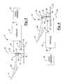
- FIG. 3is a cross-sectional view of the instrument cluster of FIG. 1 ;
- FIG. 4is an exemplary cross-sectional view of an instrument cluster according to another example of the present teachings and including a mirror having a reflector surface internal to its body and being coupled to a motor through a cannulated shaft;
- FIG. 5is a cross-sectional view of the mirror shown in FIGS. 1 and 3 ;
- FIG. 6is a cross-sectional view of the mirror shown in FIG. 4 .
- the instrument cluster 10can include a fascia 12 having a display field 14 .
- the display field 14can comprise a dial plaque 18 .
- the dial plaque 18in one exemplary embodiment may be taken to be representative of a speedometer display with low values at the left end and higher values toward the right-most or clockwise end.
- the dial plaquecan comprise a set of indicia 20 arranged generally around the dial plaque 18 to indicate a measured quantity (such as a vehicle speed).
- dial plaque 18has been representative of a speedometer to indicate vehicle speed
- the dial plaque 18can be configured to represent indicia indicative of any measured quantity such as, but not limited to, engine speed (a tachometer), a coolant temperature, a fuel level, an oil pressure, a cabin temperature, and outside temperature, time (a clock) and the like.
- the cluster 10can be arranged in any vehicle, such as an automobile, an aircraft, a boat, or for various parameters in a power plant.
- the indicia 20can be in the form of increment or scale markers 22 that may be preprinted on the dial plaque 18 to give values to the measured quantities in miles per hour, kilometers per hour, degrees, rpm, psi, minutes, etc.
- the outline of the dial plaque 18may also be printed, embossed or otherwise created on the fascia 12 of the cluster 10 for function and aesthetic appeal.
- Various non-analog displays or “telltales”collectively referred to at reference numeral 24 can include a low fuel display 26 , turn signal arrows 30 , 32 , engine temperature 34 , high beam light 36 and check engine 38 . Other telltales may also be provided. It will be noted that the telltales 24 can be physically arranged so as to correspond generally at an elevation on the dial plaque 18 consistent with the indicia 20 .
- a dial plaque 18 ′can be divided into multiple display regions 18 a , 18 b and 18 c for example.
- Each display region 18 a , 18 b and 18 ccan be configured to correspond to a different measured quantity (vehicle speed, engine speed and others identified above).
- each display region 18 a , 18 b and 18 ccan have its own unique set of indicia 20 a , 20 b and 20 c.
- illumination markersare created in the display field 14 around a 360° sweep of the dial plaque 18 to identify a desired, measured quantity value on the dial plaque 18 , such as at the indicia 20 as well as concurrently illuminating any combination of the telltales 24 identified above.
- These illumination markersare created by a light source 40 , which operates in an on/off mode under the control of a high-speed controller 44 .
- the light source 40can comprise a diode laser.
- the controller 44can be configured to receive vehicle inputs 46 ( FIG. 3 ) from various vehicle components 48 .
- the controller 44can include signal interpretation algorithms that interpret the vehicle inputs 46 and generate a set of light source signals as will be described.
- multiple transducerscan be provided that are capable of sending electrical signals representing instantaneous values of the various measure quantities.
- the conversion of the electrical signals from analog to digital formmay be carried out either within the controller 44 or externally thereof by a suitable A/D converter according to the preferences of the system.
- the light source 40is configured to output an incident beam of light 50 in a direction toward an optical device 52 that is mounted for rotation about an axis 54 .
- the optical device 52can be a simple curved surface mirror (like in this example embodiment) or other more complex optical components or systems that are capable to redirect and spread or focus the incident light.
- the optical device 52can have a reflective surface 56 ( FIG. 3 ).
- the optical device 52can be rotated by way of a shaft 58 that extends from a motor 62 at a high and continuous rate of speed so that the light reflected off the optical device 52 (hereinafter referred to as a secondary beam 66 ) sweeps angularly across the display field 14 from left to right in a clockwise fashion as explained in greater detail below.
- the optical device 52is located generally within a boundary of the dial plaque 18 and is operable to reflect light 360° around the dial plaque 18 to illuminate in any combination the indicia 20 and the telltales 24 .
- the secondary beam 66 that is reflected off of the optical device 52can also be reflected toward a photo-detector sensor 70 , the output of which is connected as an input 72 to the controller 44 for calibrating or “zeroing” purposes explained in detail below.
- a signal, hereinafter angular position signal 74can be sent from the motor 62 to the controller 44 indicative of an angular position of the shaft 58 (and therefore the angular position of the optical device 52 ).
- the motor 62can be a brushless DC motor.
- the light source 40can emit the incident beam 50 in a direction along the mirror axis 54 .
- the optical device 52is operable to reflect the incident light 50 as the secondary beam 66 around the dial plaque 18 in 360° of motion.
- the light source 40can be turned on to produce a calibration pulse, which is directed toward the photo-detector 70 .
- 960 pulses across a speedometer range of 150 miles per hourallows 0.156 miles per hour resolution between consecutive pulses.
- the vehicle inputs 46are converted to a pulse count representing approximately one-third of the total pulse count required to displace the secondary beam 66 the full width of the display field 14 .
- the controller 44outputs a signal, hereinafter light signal 80 that turns the light source 40 on and a stripe-like marker of light 82 ( FIG.
- the light signal 80can include light duration and starting point with regard to the angular position signal 74 of the motor shaft 58 .
- the controller 44can also output a signal, hereinafter a shaft angular position control signal 84 to the motor 62 .
- the controller 44can also have a light source driving function that compares the light signal 80 and the angular position signal 74 , determined by signal interpretation algorithms in the controller 44 and switch the light source 40 on/off per the comparison result.
- the controller 44can output a signal (such as light signal 80 described above) such that the light source 40 comes on at strategic times to create secondary beams 66 a , 66 b and 66 c for illumination markers 82 a , 82 b and 82 c at each display region 18 a , 18 b and 18 c , respectively.
- a signalsuch as light signal 80 described above
- data from the vehicle inputs 46can be converted to pulse counts to cause the light source 40 to come on at strategic times representing appropriate locations for illumination within the display field 14 to show the measured quantities (such as illuminate at an appropriate location on the indicia 20 ( 20 a , 20 b , 20 c ; FIG. 2 ) and/or illuminate any of the telltales 24 ).
- the display field 14is scanned repeatedly at a rate of approximately fifty times per second.
- each illumination markersuch as at 82 ( 82 a , 82 b , 82 c ; FIG. 2 ) is “refreshed” about fifty times per second and the characteristics of human sight are such that flicker will not be detected.
- the mirrorcan be rotated at a constant speed such as, but not limited to 3600 RPM, 60 Hz. The human eye will tend to blend the optical stimuli to create the appearance of continuous illumination markers in the display field 14 .
- the telltales 24may be physically defined by embossed outlines and more reflective or diffusive surface patterns to cause illumination blending.
- the light source 40can be turned on continuously during the entire sweep across the telltales 32 , 38 , 36 , 34 , 26 , and 30 in sequence, whichever needs to be lit per the vehicle inputs 46 , so as to “paint” the entire surface of the telltales.
- the incident beam 50defines a width D and reflects off of the reflective surface 56 as the secondary beam 66 .
- the reflective surface 56can be a portion of a cylinder.
- various mirrorscan be provided having dissimilar shapes.
- the cluster 110can be configured similar to the cluster 10 and have like components identified by reference numerals increased by 100. As a result, like components will not be repeatedly described with respect to the example of FIGS. 4 and 6 .
- the light source 140is arranged on an opposite side of the fascia 112 as the motor 162 .
- the motor shaft 158is tubular and defines a cannulation 159 along its axis.
- the light source 140is configured to emit incident light 150 through the cannulation 159 of the shaft 158 and onto a reflective surface 156 defined on the optical device 152 .
- the incident light 150reflects off the reflective surface 156 of the optical device 152 as a secondary beam 166 and onto the display field 14 .
- the light source 140is operable to emit the incident light 150 generally along the axis of rotation 154 of the optical device 152 .
- such a configurationcan allow the optical device 152 to reflect a secondary beam 166 in a complete 360° sweep, thereby illuminating, in any combination, indicia and/or telltales provided on the display field 114 .
Landscapes
- Engineering & Computer Science (AREA)
- Chemical & Material Sciences (AREA)
- Combustion & Propulsion (AREA)
- Transportation (AREA)
- Mechanical Engineering (AREA)
- Physics & Mathematics (AREA)
- General Physics & Mathematics (AREA)
- Details Of Measuring Devices (AREA)
Abstract
Description
Where:
- D: the incident beam width
- α the active arc angle of the mirror reflect surface
- β the desired spread angle of the secondary beam
- θ the angle between the low edge of the secondary beam and the incident beam
Claims (20)
Priority Applications (1)
| Application Number | Priority Date | Filing Date | Title |
|---|---|---|---|
| US12/275,365US7928859B1 (en) | 2008-11-21 | 2008-11-21 | Full angle laser illuminate instrument cluster |
Applications Claiming Priority (1)
| Application Number | Priority Date | Filing Date | Title |
|---|---|---|---|
| US12/275,365US7928859B1 (en) | 2008-11-21 | 2008-11-21 | Full angle laser illuminate instrument cluster |
Publications (1)
| Publication Number | Publication Date |
|---|---|
| US7928859B1true US7928859B1 (en) | 2011-04-19 |
Family
ID=43858636
Family Applications (1)
| Application Number | Title | Priority Date | Filing Date |
|---|---|---|---|
| US12/275,365Expired - Fee RelatedUS7928859B1 (en) | 2008-11-21 | 2008-11-21 | Full angle laser illuminate instrument cluster |
Country Status (1)
| Country | Link |
|---|---|
| US (1) | US7928859B1 (en) |
Cited By (8)
| Publication number | Priority date | Publication date | Assignee | Title |
|---|---|---|---|---|
| US20110043347A1 (en)* | 2008-12-09 | 2011-02-24 | Yazaki Corporation | Control method for switching between scales in vehicular instrument, and vehicular instrument |
| US20110271896A1 (en)* | 2010-05-07 | 2011-11-10 | Whirlpool Corporation | User interface for a controller |
| US20120255208A1 (en)* | 2011-04-08 | 2012-10-11 | GM Global Technology Operations LLC | Display apparatus for a vehicle and method for producing the display apparatus |
| DE102013011309A1 (en) | 2013-07-06 | 2015-01-08 | Audi Ag | Display device of a motor vehicle |
| US20170075208A1 (en)* | 2015-09-10 | 2017-03-16 | Raghavendra Narayan Mudagal | Instrument cluster with pointer embedded with projector |
| US9909906B2 (en)* | 2016-04-22 | 2018-03-06 | Denso International America, Inc. | Indicating device with dial plate having grooves |
| US10203229B2 (en) | 2014-04-11 | 2019-02-12 | Continental Automotive Systems, Inc. | Pointerless instrument cluster gauge |
| US10317259B2 (en) | 2014-09-30 | 2019-06-11 | Continental Automotive Systems, Inc. | Gauge utilizing light leakage to illuminate the scale of a dial and instrument panel with the gauge |
Citations (28)
| Publication number | Priority date | Publication date | Assignee | Title |
|---|---|---|---|---|
| US134956A (en) | 1873-01-14 | Improvement in cloth-steaming machines | ||
| US2285374A (en) | 1939-10-07 | 1942-06-02 | Telefunken Gmbh | Push button for radio apparatus |
| US3448458A (en) | 1967-06-16 | 1969-06-03 | Ncr Co | Laser recorder with scanning and display systems |
| US3781092A (en) | 1971-06-28 | 1973-12-25 | D Sussman | Monitoring system |
| US3890033A (en) | 1973-02-13 | 1975-06-17 | Parsons & Co Sir Howard G | Adjustable-spring attenuator for radiated beams |
| US4484179A (en) | 1980-04-16 | 1984-11-20 | At&T Bell Laboratories | Touch position sensitive surface |
| US4553842A (en) | 1983-05-09 | 1985-11-19 | Illinois Tool Works Inc. | Two dimensional optical position indicating apparatus |
| US4761715A (en) | 1987-03-25 | 1988-08-02 | Beede Electrical Instrument Co., Inc. | Laser pointer |
| US4762990A (en) | 1985-10-21 | 1988-08-09 | International Business Machines Corporation | Data processing input interface determining position of object |
| US5031985A (en) | 1988-12-14 | 1991-07-16 | Koito Manufacturing Co., Ltd. | Optical switch system and apparatus |
| US5046806A (en) | 1990-02-22 | 1991-09-10 | Cst Coldswitch Holdings Inc. | Single fibre control switches |
| US5090791A (en) | 1988-09-16 | 1992-02-25 | John S. Kidder | Self-illuminated fibre optic switch |
| US5220409A (en) | 1988-12-19 | 1993-06-15 | Amp Incorporated | Light beam detection utilizing hologram |
| US5294940A (en) | 1991-02-06 | 1994-03-15 | Dale A. Wennagel | Pulsed laser optical display device |
| US5353735A (en) | 1991-04-23 | 1994-10-11 | Yazaki Corporation | Indicating instrument system |
| US5424533A (en) | 1994-06-21 | 1995-06-13 | United Technologies Corporation | Self illuminating touch activated optical switch |
| US5805119A (en) | 1992-10-13 | 1998-09-08 | General Motors Corporation | Vehicle projected display using deformable mirror device |
| US5825495A (en) | 1995-02-27 | 1998-10-20 | Lockheed Martin Corporation | Bright field illumination system |
| US5971569A (en) | 1997-06-11 | 1999-10-26 | Steris Corporation | Surgical light with stacked elliptical reflector |
| US5982352A (en) | 1992-09-18 | 1999-11-09 | Pryor; Timothy R. | Method for providing human input to a computer |
| US6766036B1 (en) | 1999-07-08 | 2004-07-20 | Timothy R. Pryor | Camera based man machine interfaces |
| US7084859B1 (en) | 1992-09-18 | 2006-08-01 | Pryor Timothy R | Programmable tactile touch screen displays and man-machine interfaces for improved vehicle instrumentation and telematics |
| US7097316B2 (en) | 2003-08-29 | 2006-08-29 | Calsonic Kansei Corporation | Display unit for vehicle |
| US7193729B1 (en) | 2004-04-29 | 2007-03-20 | Yazaki North America, Inc | Instrument cluster with laser beam illumination |
| US20080173233A1 (en)* | 2007-01-23 | 2008-07-24 | Denso International America, Inc. | Indicating instrument with light pointer |
| US7448341B2 (en)* | 2006-12-11 | 2008-11-11 | Denso International America, Inc. | Gauge laser pointer |
| US7466843B2 (en) | 2000-07-07 | 2008-12-16 | Pryor Timothy R | Multi-functional control and entertainment systems |
| US7798026B2 (en)* | 2006-01-11 | 2010-09-21 | Continental Automotive Systems Us, Inc. | Generated pointer image for an instrument cluster display |
- 2008
- 2008-11-21USUS12/275,365patent/US7928859B1/ennot_activeExpired - Fee Related
Patent Citations (29)
| Publication number | Priority date | Publication date | Assignee | Title |
|---|---|---|---|---|
| US134956A (en) | 1873-01-14 | Improvement in cloth-steaming machines | ||
| US2285374A (en) | 1939-10-07 | 1942-06-02 | Telefunken Gmbh | Push button for radio apparatus |
| US3448458A (en) | 1967-06-16 | 1969-06-03 | Ncr Co | Laser recorder with scanning and display systems |
| US3781092A (en) | 1971-06-28 | 1973-12-25 | D Sussman | Monitoring system |
| US3890033A (en) | 1973-02-13 | 1975-06-17 | Parsons & Co Sir Howard G | Adjustable-spring attenuator for radiated beams |
| US4484179B1 (en) | 1980-04-16 | 1989-03-28 | ||
| US4484179A (en) | 1980-04-16 | 1984-11-20 | At&T Bell Laboratories | Touch position sensitive surface |
| US4553842A (en) | 1983-05-09 | 1985-11-19 | Illinois Tool Works Inc. | Two dimensional optical position indicating apparatus |
| US4762990A (en) | 1985-10-21 | 1988-08-09 | International Business Machines Corporation | Data processing input interface determining position of object |
| US4761715A (en) | 1987-03-25 | 1988-08-02 | Beede Electrical Instrument Co., Inc. | Laser pointer |
| US5090791A (en) | 1988-09-16 | 1992-02-25 | John S. Kidder | Self-illuminated fibre optic switch |
| US5031985A (en) | 1988-12-14 | 1991-07-16 | Koito Manufacturing Co., Ltd. | Optical switch system and apparatus |
| US5220409A (en) | 1988-12-19 | 1993-06-15 | Amp Incorporated | Light beam detection utilizing hologram |
| US5046806A (en) | 1990-02-22 | 1991-09-10 | Cst Coldswitch Holdings Inc. | Single fibre control switches |
| US5294940A (en) | 1991-02-06 | 1994-03-15 | Dale A. Wennagel | Pulsed laser optical display device |
| US5353735A (en) | 1991-04-23 | 1994-10-11 | Yazaki Corporation | Indicating instrument system |
| US7084859B1 (en) | 1992-09-18 | 2006-08-01 | Pryor Timothy R | Programmable tactile touch screen displays and man-machine interfaces for improved vehicle instrumentation and telematics |
| US5982352A (en) | 1992-09-18 | 1999-11-09 | Pryor; Timothy R. | Method for providing human input to a computer |
| US5805119A (en) | 1992-10-13 | 1998-09-08 | General Motors Corporation | Vehicle projected display using deformable mirror device |
| US5424533A (en) | 1994-06-21 | 1995-06-13 | United Technologies Corporation | Self illuminating touch activated optical switch |
| US5825495A (en) | 1995-02-27 | 1998-10-20 | Lockheed Martin Corporation | Bright field illumination system |
| US5971569A (en) | 1997-06-11 | 1999-10-26 | Steris Corporation | Surgical light with stacked elliptical reflector |
| US6766036B1 (en) | 1999-07-08 | 2004-07-20 | Timothy R. Pryor | Camera based man machine interfaces |
| US7466843B2 (en) | 2000-07-07 | 2008-12-16 | Pryor Timothy R | Multi-functional control and entertainment systems |
| US7097316B2 (en) | 2003-08-29 | 2006-08-29 | Calsonic Kansei Corporation | Display unit for vehicle |
| US7193729B1 (en) | 2004-04-29 | 2007-03-20 | Yazaki North America, Inc | Instrument cluster with laser beam illumination |
| US7798026B2 (en)* | 2006-01-11 | 2010-09-21 | Continental Automotive Systems Us, Inc. | Generated pointer image for an instrument cluster display |
| US7448341B2 (en)* | 2006-12-11 | 2008-11-11 | Denso International America, Inc. | Gauge laser pointer |
| US20080173233A1 (en)* | 2007-01-23 | 2008-07-24 | Denso International America, Inc. | Indicating instrument with light pointer |
Non-Patent Citations (2)
| Title |
|---|
| U.S. Appl. No. 12/422,692, filed Apr. 13, 2009, Boyd et al. |
| U.S. Appl. No. 12/435,096, filed May 4, 2009, Boyd et al. |
Cited By (12)
| Publication number | Priority date | Publication date | Assignee | Title |
|---|---|---|---|---|
| US20110043347A1 (en)* | 2008-12-09 | 2011-02-24 | Yazaki Corporation | Control method for switching between scales in vehicular instrument, and vehicular instrument |
| US8531283B2 (en)* | 2008-12-09 | 2013-09-10 | Yazaki Corporation | Control method for switching between scales in vehicular instrument, and vehicular instrument |
| US20110271896A1 (en)* | 2010-05-07 | 2011-11-10 | Whirlpool Corporation | User interface for a controller |
| US8813676B2 (en)* | 2010-05-07 | 2014-08-26 | Whirlpool Corporation | User interface for a controller |
| US20120255208A1 (en)* | 2011-04-08 | 2012-10-11 | GM Global Technology Operations LLC | Display apparatus for a vehicle and method for producing the display apparatus |
| US8931909B2 (en)* | 2011-04-08 | 2015-01-13 | GM Global Technology Operations LLC | Display apparatus for a vehicle and method for producing the display apparatus |
| DE102013011309A1 (en) | 2013-07-06 | 2015-01-08 | Audi Ag | Display device of a motor vehicle |
| DE102013011309B4 (en)* | 2013-07-06 | 2020-02-06 | Audi Ag | Display device of a motor vehicle |
| US10203229B2 (en) | 2014-04-11 | 2019-02-12 | Continental Automotive Systems, Inc. | Pointerless instrument cluster gauge |
| US10317259B2 (en) | 2014-09-30 | 2019-06-11 | Continental Automotive Systems, Inc. | Gauge utilizing light leakage to illuminate the scale of a dial and instrument panel with the gauge |
| US20170075208A1 (en)* | 2015-09-10 | 2017-03-16 | Raghavendra Narayan Mudagal | Instrument cluster with pointer embedded with projector |
| US9909906B2 (en)* | 2016-04-22 | 2018-03-06 | Denso International America, Inc. | Indicating device with dial plate having grooves |
Similar Documents
| Publication | Publication Date | Title |
|---|---|---|
| US7928859B1 (en) | Full angle laser illuminate instrument cluster | |
| US7954965B1 (en) | Method for multiple gauges in a scanning laser based display device | |
| US6714126B2 (en) | Vehicle indicator unit having wowing and graduation lighting function | |
| JP5578918B2 (en) | Light guide plate and pointer instrument having the same | |
| US6915758B2 (en) | Display device for vehicle | |
| US7193729B1 (en) | Instrument cluster with laser beam illumination | |
| US20050174308A1 (en) | Rotational light emitting display apparatus | |
| US20070157745A1 (en) | Generated pointer image for an instrument cluster display | |
| CA2590797A1 (en) | Automated monitoring of analog guages | |
| EP2426465A1 (en) | Instrument lighting device | |
| JP2009145098A (en) | Pointer illumination device | |
| JP5413744B2 (en) | Display device | |
| JP2011222233A (en) | Light guide plate, and display device equipped with the same | |
| JP2003194596A (en) | display | |
| US20100236471A1 (en) | Free shape gauge by laser pointer | |
| ATE420339T1 (en) | SPEED INDICATOR FOR A VEHICLE EQUIPPED WITH AN ADAPTIVE CRUISE CONTROL SYSTEM | |
| JP5344381B2 (en) | Pointer instrument | |
| US8382348B2 (en) | Display device for vehicle | |
| JP2003215142A (en) | Measuring instrument for vehicle | |
| JPH06323874A (en) | Display device | |
| JP2009198465A (en) | Pointer instrument | |
| JP2009262583A (en) | Long light guide member, lighting system having the long light guide member, and warning system having the lighting system | |
| JP4744204B2 (en) | Instrument lighting structure | |
| JP2005227258A (en) | Instrument lighting structure | |
| WO2006112811A1 (en) | Measuring instrument having location-controlled display |
Legal Events
| Date | Code | Title | Description |
|---|---|---|---|
| AS | Assignment | Owner name:YAZAKI NORTH AMERICA, INC., MICHIGAN Free format text:ASSIGNMENT OF ASSIGNORS INTEREST;ASSIGNORS:LI, KANG;BOYD, MICHAEL;REEL/FRAME:021873/0471 Effective date:20081121 | |
| STCF | Information on status: patent grant | Free format text:PATENTED CASE | |
| REMI | Maintenance fee reminder mailed | ||
| FPAY | Fee payment | Year of fee payment:4 | |
| SULP | Surcharge for late payment | ||
| FEPP | Fee payment procedure | Free format text:7.5 YR SURCHARGE - LATE PMT W/IN 6 MO, LARGE ENTITY (ORIGINAL EVENT CODE: M1555); ENTITY STATUS OF PATENT OWNER: LARGE ENTITY | |
| MAFP | Maintenance fee payment | Free format text:PAYMENT OF MAINTENANCE FEE, 8TH YEAR, LARGE ENTITY (ORIGINAL EVENT CODE: M1552); ENTITY STATUS OF PATENT OWNER: LARGE ENTITY Year of fee payment:8 | |
| FEPP | Fee payment procedure | Free format text:MAINTENANCE FEE REMINDER MAILED (ORIGINAL EVENT CODE: REM.); ENTITY STATUS OF PATENT OWNER: LARGE ENTITY | |
| LAPS | Lapse for failure to pay maintenance fees | Free format text:PATENT EXPIRED FOR FAILURE TO PAY MAINTENANCE FEES (ORIGINAL EVENT CODE: EXP.); ENTITY STATUS OF PATENT OWNER: LARGE ENTITY | |
| STCH | Information on status: patent discontinuation | Free format text:PATENT EXPIRED DUE TO NONPAYMENT OF MAINTENANCE FEES UNDER 37 CFR 1.362 | |
| FP | Lapsed due to failure to pay maintenance fee | Effective date:20230419 |