US7928693B2 - Plugin hybrid electric vehicle with V2G optimization system - Google Patents
Plugin hybrid electric vehicle with V2G optimization systemDownload PDFInfo
- Publication number
- US7928693B2 US7928693B2US12/048,183US4818308AUS7928693B2US 7928693 B2US7928693 B2US 7928693B2US 4818308 AUS4818308 AUS 4818308AUS 7928693 B2US7928693 B2US 7928693B2
- Authority
- US
- United States
- Prior art keywords
- vehicle
- battery
- power source
- data
- computer
- Prior art date
- Legal status (The legal status is an assumption and is not a legal conclusion. Google has not performed a legal analysis and makes no representation as to the accuracy of the status listed.)
- Active, expires
Links
- 238000005457optimizationMethods0.000titledescription5
- 239000000446fuelSubstances0.000claimsabstractdescription37
- 238000003860storageMethods0.000claimsdescription26
- 238000004891communicationMethods0.000claimsdescription24
- 230000005540biological transmissionEffects0.000claimsdescription7
- 238000007599dischargingMethods0.000claimsdescription4
- 238000005265energy consumptionMethods0.000claimsdescription4
- 238000004146energy storageMethods0.000claimsdescription2
- 230000008901benefitEffects0.000description21
- 230000015654memoryEffects0.000description15
- 238000000034methodMethods0.000description14
- 230000005611electricityEffects0.000description12
- 241000156302Porcine hemagglutinating encephalomyelitis virusSpecies0.000description11
- 238000004590computer programMethods0.000description9
- 239000007789gasSubstances0.000description9
- 230000008569processEffects0.000description9
- 238000010586diagramMethods0.000description7
- 230000003287optical effectEffects0.000description6
- OKTJSMMVPCPJKN-UHFFFAOYSA-NCarbonChemical compound[C]OKTJSMMVPCPJKN-UHFFFAOYSA-N0.000description5
- 229910052799carbonInorganic materials0.000description5
- 239000003502gasolineSubstances0.000description4
- VNWKTOKETHGBQD-UHFFFAOYSA-NmethaneChemical compoundCVNWKTOKETHGBQD-UHFFFAOYSA-N0.000description4
- 230000001172regenerating effectEffects0.000description4
- 230000000007visual effectEffects0.000description4
- 230000008859changeEffects0.000description3
- 238000002485combustion reactionMethods0.000description3
- 229910052739hydrogenInorganic materials0.000description3
- 239000001257hydrogenSubstances0.000description3
- 238000012545processingMethods0.000description3
- LFQSCWFLJHTTHZ-UHFFFAOYSA-NEthanolChemical compoundCCOLFQSCWFLJHTTHZ-UHFFFAOYSA-N0.000description2
- UFHFLCQGNIYNRP-UHFFFAOYSA-NHydrogenChemical compound[H][H]UFHFLCQGNIYNRP-UHFFFAOYSA-N0.000description2
- 230000009471actionEffects0.000description2
- 238000004458analytical methodMethods0.000description2
- 230000008878couplingEffects0.000description2
- 238000010168coupling processMethods0.000description2
- 238000005859coupling reactionMethods0.000description2
- -1dieselSubstances0.000description2
- 230000006870functionEffects0.000description2
- 230000010365information processingEffects0.000description2
- 238000007726management methodMethods0.000description2
- 239000003345natural gasSubstances0.000description2
- 239000004065semiconductorSubstances0.000description2
- 230000006978adaptationEffects0.000description1
- 230000009286beneficial effectEffects0.000description1
- 230000002457bidirectional effectEffects0.000description1
- 230000001413cellular effectEffects0.000description1
- 230000000295complement effectEffects0.000description1
- 230000000694effectsEffects0.000description1
- 238000003912environmental pollutionMethods0.000description1
- 239000000835fiberSubstances0.000description1
- 239000002803fossil fuelSubstances0.000description1
- 150000002431hydrogenChemical class0.000description1
- 238000004519manufacturing processMethods0.000description1
- 238000012986modificationMethods0.000description1
- 230000004048modificationEffects0.000description1
- 238000010248power generationMethods0.000description1
- 230000009467reductionEffects0.000description1
- 230000008672reprogrammingEffects0.000description1
- 238000011160researchMethods0.000description1
- 239000007787solidSubstances0.000description1
Images


Classifications
- B—PERFORMING OPERATIONS; TRANSPORTING
- B60—VEHICLES IN GENERAL
- B60L—PROPULSION OF ELECTRICALLY-PROPELLED VEHICLES; SUPPLYING ELECTRIC POWER FOR AUXILIARY EQUIPMENT OF ELECTRICALLY-PROPELLED VEHICLES; ELECTRODYNAMIC BRAKE SYSTEMS FOR VEHICLES IN GENERAL; MAGNETIC SUSPENSION OR LEVITATION FOR VEHICLES; MONITORING OPERATING VARIABLES OF ELECTRICALLY-PROPELLED VEHICLES; ELECTRIC SAFETY DEVICES FOR ELECTRICALLY-PROPELLED VEHICLES
- B60L53/00—Methods of charging batteries, specially adapted for electric vehicles; Charging stations or on-board charging equipment therefor; Exchange of energy storage elements in electric vehicles
- B60L53/10—Methods of charging batteries, specially adapted for electric vehicles; Charging stations or on-board charging equipment therefor; Exchange of energy storage elements in electric vehicles characterised by the energy transfer between the charging station and the vehicle
- B60L53/14—Conductive energy transfer
- B—PERFORMING OPERATIONS; TRANSPORTING
- B60—VEHICLES IN GENERAL
- B60L—PROPULSION OF ELECTRICALLY-PROPELLED VEHICLES; SUPPLYING ELECTRIC POWER FOR AUXILIARY EQUIPMENT OF ELECTRICALLY-PROPELLED VEHICLES; ELECTRODYNAMIC BRAKE SYSTEMS FOR VEHICLES IN GENERAL; MAGNETIC SUSPENSION OR LEVITATION FOR VEHICLES; MONITORING OPERATING VARIABLES OF ELECTRICALLY-PROPELLED VEHICLES; ELECTRIC SAFETY DEVICES FOR ELECTRICALLY-PROPELLED VEHICLES
- B60L3/00—Electric devices on electrically-propelled vehicles for safety purposes; Monitoring operating variables, e.g. speed, deceleration or energy consumption
- B60L3/0023—Detecting, eliminating, remedying or compensating for drive train abnormalities, e.g. failures within the drive train
- B60L3/0046—Detecting, eliminating, remedying or compensating for drive train abnormalities, e.g. failures within the drive train relating to electric energy storage systems, e.g. batteries or capacitors
- B—PERFORMING OPERATIONS; TRANSPORTING
- B60—VEHICLES IN GENERAL
- B60L—PROPULSION OF ELECTRICALLY-PROPELLED VEHICLES; SUPPLYING ELECTRIC POWER FOR AUXILIARY EQUIPMENT OF ELECTRICALLY-PROPELLED VEHICLES; ELECTRODYNAMIC BRAKE SYSTEMS FOR VEHICLES IN GENERAL; MAGNETIC SUSPENSION OR LEVITATION FOR VEHICLES; MONITORING OPERATING VARIABLES OF ELECTRICALLY-PROPELLED VEHICLES; ELECTRIC SAFETY DEVICES FOR ELECTRICALLY-PROPELLED VEHICLES
- B60L53/00—Methods of charging batteries, specially adapted for electric vehicles; Charging stations or on-board charging equipment therefor; Exchange of energy storage elements in electric vehicles
- B60L53/30—Constructional details of charging stations
- B60L53/305—Communication interfaces
- B—PERFORMING OPERATIONS; TRANSPORTING
- B60—VEHICLES IN GENERAL
- B60L—PROPULSION OF ELECTRICALLY-PROPELLED VEHICLES; SUPPLYING ELECTRIC POWER FOR AUXILIARY EQUIPMENT OF ELECTRICALLY-PROPELLED VEHICLES; ELECTRODYNAMIC BRAKE SYSTEMS FOR VEHICLES IN GENERAL; MAGNETIC SUSPENSION OR LEVITATION FOR VEHICLES; MONITORING OPERATING VARIABLES OF ELECTRICALLY-PROPELLED VEHICLES; ELECTRIC SAFETY DEVICES FOR ELECTRICALLY-PROPELLED VEHICLES
- B60L53/00—Methods of charging batteries, specially adapted for electric vehicles; Charging stations or on-board charging equipment therefor; Exchange of energy storage elements in electric vehicles
- B60L53/60—Monitoring or controlling charging stations
- B60L53/63—Monitoring or controlling charging stations in response to network capacity
- B—PERFORMING OPERATIONS; TRANSPORTING
- B60—VEHICLES IN GENERAL
- B60L—PROPULSION OF ELECTRICALLY-PROPELLED VEHICLES; SUPPLYING ELECTRIC POWER FOR AUXILIARY EQUIPMENT OF ELECTRICALLY-PROPELLED VEHICLES; ELECTRODYNAMIC BRAKE SYSTEMS FOR VEHICLES IN GENERAL; MAGNETIC SUSPENSION OR LEVITATION FOR VEHICLES; MONITORING OPERATING VARIABLES OF ELECTRICALLY-PROPELLED VEHICLES; ELECTRIC SAFETY DEVICES FOR ELECTRICALLY-PROPELLED VEHICLES
- B60L53/00—Methods of charging batteries, specially adapted for electric vehicles; Charging stations or on-board charging equipment therefor; Exchange of energy storage elements in electric vehicles
- B60L53/60—Monitoring or controlling charging stations
- B60L53/64—Optimising energy costs, e.g. responding to electricity rates
- B—PERFORMING OPERATIONS; TRANSPORTING
- B60—VEHICLES IN GENERAL
- B60L—PROPULSION OF ELECTRICALLY-PROPELLED VEHICLES; SUPPLYING ELECTRIC POWER FOR AUXILIARY EQUIPMENT OF ELECTRICALLY-PROPELLED VEHICLES; ELECTRODYNAMIC BRAKE SYSTEMS FOR VEHICLES IN GENERAL; MAGNETIC SUSPENSION OR LEVITATION FOR VEHICLES; MONITORING OPERATING VARIABLES OF ELECTRICALLY-PROPELLED VEHICLES; ELECTRIC SAFETY DEVICES FOR ELECTRICALLY-PROPELLED VEHICLES
- B60L53/00—Methods of charging batteries, specially adapted for electric vehicles; Charging stations or on-board charging equipment therefor; Exchange of energy storage elements in electric vehicles
- B60L53/60—Monitoring or controlling charging stations
- B60L53/65—Monitoring or controlling charging stations involving identification of vehicles or their battery types
- B—PERFORMING OPERATIONS; TRANSPORTING
- B60—VEHICLES IN GENERAL
- B60L—PROPULSION OF ELECTRICALLY-PROPELLED VEHICLES; SUPPLYING ELECTRIC POWER FOR AUXILIARY EQUIPMENT OF ELECTRICALLY-PROPELLED VEHICLES; ELECTRODYNAMIC BRAKE SYSTEMS FOR VEHICLES IN GENERAL; MAGNETIC SUSPENSION OR LEVITATION FOR VEHICLES; MONITORING OPERATING VARIABLES OF ELECTRICALLY-PROPELLED VEHICLES; ELECTRIC SAFETY DEVICES FOR ELECTRICALLY-PROPELLED VEHICLES
- B60L53/00—Methods of charging batteries, specially adapted for electric vehicles; Charging stations or on-board charging equipment therefor; Exchange of energy storage elements in electric vehicles
- B60L53/60—Monitoring or controlling charging stations
- B60L53/66—Data transfer between charging stations and vehicles
- B60L53/665—Methods related to measuring, billing or payment
- B—PERFORMING OPERATIONS; TRANSPORTING
- B60—VEHICLES IN GENERAL
- B60L—PROPULSION OF ELECTRICALLY-PROPELLED VEHICLES; SUPPLYING ELECTRIC POWER FOR AUXILIARY EQUIPMENT OF ELECTRICALLY-PROPELLED VEHICLES; ELECTRODYNAMIC BRAKE SYSTEMS FOR VEHICLES IN GENERAL; MAGNETIC SUSPENSION OR LEVITATION FOR VEHICLES; MONITORING OPERATING VARIABLES OF ELECTRICALLY-PROPELLED VEHICLES; ELECTRIC SAFETY DEVICES FOR ELECTRICALLY-PROPELLED VEHICLES
- B60L55/00—Arrangements for supplying energy stored within a vehicle to a power network, i.e. vehicle-to-grid [V2G] arrangements
- B—PERFORMING OPERATIONS; TRANSPORTING
- B60—VEHICLES IN GENERAL
- B60L—PROPULSION OF ELECTRICALLY-PROPELLED VEHICLES; SUPPLYING ELECTRIC POWER FOR AUXILIARY EQUIPMENT OF ELECTRICALLY-PROPELLED VEHICLES; ELECTRODYNAMIC BRAKE SYSTEMS FOR VEHICLES IN GENERAL; MAGNETIC SUSPENSION OR LEVITATION FOR VEHICLES; MONITORING OPERATING VARIABLES OF ELECTRICALLY-PROPELLED VEHICLES; ELECTRIC SAFETY DEVICES FOR ELECTRICALLY-PROPELLED VEHICLES
- B60L58/00—Methods or circuit arrangements for monitoring or controlling batteries or fuel cells, specially adapted for electric vehicles
- B60L58/10—Methods or circuit arrangements for monitoring or controlling batteries or fuel cells, specially adapted for electric vehicles for monitoring or controlling batteries
- B60L58/12—Methods or circuit arrangements for monitoring or controlling batteries or fuel cells, specially adapted for electric vehicles for monitoring or controlling batteries responding to state of charge [SoC]
- B—PERFORMING OPERATIONS; TRANSPORTING
- B60—VEHICLES IN GENERAL
- B60W—CONJOINT CONTROL OF VEHICLE SUB-UNITS OF DIFFERENT TYPE OR DIFFERENT FUNCTION; CONTROL SYSTEMS SPECIALLY ADAPTED FOR HYBRID VEHICLES; ROAD VEHICLE DRIVE CONTROL SYSTEMS FOR PURPOSES NOT RELATED TO THE CONTROL OF A PARTICULAR SUB-UNIT
- B60W10/00—Conjoint control of vehicle sub-units of different type or different function
- B60W10/24—Conjoint control of vehicle sub-units of different type or different function including control of energy storage means
- B60W10/26—Conjoint control of vehicle sub-units of different type or different function including control of energy storage means for electrical energy, e.g. batteries or capacitors
- B—PERFORMING OPERATIONS; TRANSPORTING
- B60—VEHICLES IN GENERAL
- B60W—CONJOINT CONTROL OF VEHICLE SUB-UNITS OF DIFFERENT TYPE OR DIFFERENT FUNCTION; CONTROL SYSTEMS SPECIALLY ADAPTED FOR HYBRID VEHICLES; ROAD VEHICLE DRIVE CONTROL SYSTEMS FOR PURPOSES NOT RELATED TO THE CONTROL OF A PARTICULAR SUB-UNIT
- B60W20/00—Control systems specially adapted for hybrid vehicles
- B60W20/10—Controlling the power contribution of each of the prime movers to meet required power demand
- B60W20/11—Controlling the power contribution of each of the prime movers to meet required power demand using model predictive control [MPC] strategies, i.e. control methods based on models predicting performance
- B—PERFORMING OPERATIONS; TRANSPORTING
- B60—VEHICLES IN GENERAL
- B60W—CONJOINT CONTROL OF VEHICLE SUB-UNITS OF DIFFERENT TYPE OR DIFFERENT FUNCTION; CONTROL SYSTEMS SPECIALLY ADAPTED FOR HYBRID VEHICLES; ROAD VEHICLE DRIVE CONTROL SYSTEMS FOR PURPOSES NOT RELATED TO THE CONTROL OF A PARTICULAR SUB-UNIT
- B60W20/00—Control systems specially adapted for hybrid vehicles
- B60W20/10—Controlling the power contribution of each of the prime movers to meet required power demand
- B60W20/13—Controlling the power contribution of each of the prime movers to meet required power demand in order to stay within battery power input or output limits; in order to prevent overcharging or battery depletion
- B—PERFORMING OPERATIONS; TRANSPORTING
- B60—VEHICLES IN GENERAL
- B60W—CONJOINT CONTROL OF VEHICLE SUB-UNITS OF DIFFERENT TYPE OR DIFFERENT FUNCTION; CONTROL SYSTEMS SPECIALLY ADAPTED FOR HYBRID VEHICLES; ROAD VEHICLE DRIVE CONTROL SYSTEMS FOR PURPOSES NOT RELATED TO THE CONTROL OF A PARTICULAR SUB-UNIT
- B60W50/00—Details of control systems for road vehicle drive control not related to the control of a particular sub-unit, e.g. process diagnostic or vehicle driver interfaces
- B60W50/0097—Predicting future conditions
- B—PERFORMING OPERATIONS; TRANSPORTING
- B60—VEHICLES IN GENERAL
- B60W—CONJOINT CONTROL OF VEHICLE SUB-UNITS OF DIFFERENT TYPE OR DIFFERENT FUNCTION; CONTROL SYSTEMS SPECIALLY ADAPTED FOR HYBRID VEHICLES; ROAD VEHICLE DRIVE CONTROL SYSTEMS FOR PURPOSES NOT RELATED TO THE CONTROL OF A PARTICULAR SUB-UNIT
- B60W20/00—Control systems specially adapted for hybrid vehicles
- B—PERFORMING OPERATIONS; TRANSPORTING
- B60—VEHICLES IN GENERAL
- B60W—CONJOINT CONTROL OF VEHICLE SUB-UNITS OF DIFFERENT TYPE OR DIFFERENT FUNCTION; CONTROL SYSTEMS SPECIALLY ADAPTED FOR HYBRID VEHICLES; ROAD VEHICLE DRIVE CONTROL SYSTEMS FOR PURPOSES NOT RELATED TO THE CONTROL OF A PARTICULAR SUB-UNIT
- B60W50/00—Details of control systems for road vehicle drive control not related to the control of a particular sub-unit, e.g. process diagnostic or vehicle driver interfaces
- B60W50/08—Interaction between the driver and the control system
- B60W50/14—Means for informing the driver, warning the driver or prompting a driver intervention
- B60W2050/146—Display means
- Y—GENERAL TAGGING OF NEW TECHNOLOGICAL DEVELOPMENTS; GENERAL TAGGING OF CROSS-SECTIONAL TECHNOLOGIES SPANNING OVER SEVERAL SECTIONS OF THE IPC; TECHNICAL SUBJECTS COVERED BY FORMER USPC CROSS-REFERENCE ART COLLECTIONS [XRACs] AND DIGESTS
- Y02—TECHNOLOGIES OR APPLICATIONS FOR MITIGATION OR ADAPTATION AGAINST CLIMATE CHANGE
- Y02E—REDUCTION OF GREENHOUSE GAS [GHG] EMISSIONS, RELATED TO ENERGY GENERATION, TRANSMISSION OR DISTRIBUTION
- Y02E60/00—Enabling technologies; Technologies with a potential or indirect contribution to GHG emissions mitigation
- Y—GENERAL TAGGING OF NEW TECHNOLOGICAL DEVELOPMENTS; GENERAL TAGGING OF CROSS-SECTIONAL TECHNOLOGIES SPANNING OVER SEVERAL SECTIONS OF THE IPC; TECHNICAL SUBJECTS COVERED BY FORMER USPC CROSS-REFERENCE ART COLLECTIONS [XRACs] AND DIGESTS
- Y02—TECHNOLOGIES OR APPLICATIONS FOR MITIGATION OR ADAPTATION AGAINST CLIMATE CHANGE
- Y02T—CLIMATE CHANGE MITIGATION TECHNOLOGIES RELATED TO TRANSPORTATION
- Y02T10/00—Road transport of goods or passengers
- Y02T10/60—Other road transportation technologies with climate change mitigation effect
- Y02T10/62—Hybrid vehicles
- Y—GENERAL TAGGING OF NEW TECHNOLOGICAL DEVELOPMENTS; GENERAL TAGGING OF CROSS-SECTIONAL TECHNOLOGIES SPANNING OVER SEVERAL SECTIONS OF THE IPC; TECHNICAL SUBJECTS COVERED BY FORMER USPC CROSS-REFERENCE ART COLLECTIONS [XRACs] AND DIGESTS
- Y02—TECHNOLOGIES OR APPLICATIONS FOR MITIGATION OR ADAPTATION AGAINST CLIMATE CHANGE
- Y02T—CLIMATE CHANGE MITIGATION TECHNOLOGIES RELATED TO TRANSPORTATION
- Y02T10/00—Road transport of goods or passengers
- Y02T10/60—Other road transportation technologies with climate change mitigation effect
- Y02T10/70—Energy storage systems for electromobility, e.g. batteries
- Y—GENERAL TAGGING OF NEW TECHNOLOGICAL DEVELOPMENTS; GENERAL TAGGING OF CROSS-SECTIONAL TECHNOLOGIES SPANNING OVER SEVERAL SECTIONS OF THE IPC; TECHNICAL SUBJECTS COVERED BY FORMER USPC CROSS-REFERENCE ART COLLECTIONS [XRACs] AND DIGESTS
- Y02—TECHNOLOGIES OR APPLICATIONS FOR MITIGATION OR ADAPTATION AGAINST CLIMATE CHANGE
- Y02T—CLIMATE CHANGE MITIGATION TECHNOLOGIES RELATED TO TRANSPORTATION
- Y02T10/00—Road transport of goods or passengers
- Y02T10/60—Other road transportation technologies with climate change mitigation effect
- Y02T10/7072—Electromobility specific charging systems or methods for batteries, ultracapacitors, supercapacitors or double-layer capacitors
- Y—GENERAL TAGGING OF NEW TECHNOLOGICAL DEVELOPMENTS; GENERAL TAGGING OF CROSS-SECTIONAL TECHNOLOGIES SPANNING OVER SEVERAL SECTIONS OF THE IPC; TECHNICAL SUBJECTS COVERED BY FORMER USPC CROSS-REFERENCE ART COLLECTIONS [XRACs] AND DIGESTS
- Y02—TECHNOLOGIES OR APPLICATIONS FOR MITIGATION OR ADAPTATION AGAINST CLIMATE CHANGE
- Y02T—CLIMATE CHANGE MITIGATION TECHNOLOGIES RELATED TO TRANSPORTATION
- Y02T90/00—Enabling technologies or technologies with a potential or indirect contribution to GHG emissions mitigation
- Y02T90/10—Technologies relating to charging of electric vehicles
- Y02T90/12—Electric charging stations
- Y—GENERAL TAGGING OF NEW TECHNOLOGICAL DEVELOPMENTS; GENERAL TAGGING OF CROSS-SECTIONAL TECHNOLOGIES SPANNING OVER SEVERAL SECTIONS OF THE IPC; TECHNICAL SUBJECTS COVERED BY FORMER USPC CROSS-REFERENCE ART COLLECTIONS [XRACs] AND DIGESTS
- Y02—TECHNOLOGIES OR APPLICATIONS FOR MITIGATION OR ADAPTATION AGAINST CLIMATE CHANGE
- Y02T—CLIMATE CHANGE MITIGATION TECHNOLOGIES RELATED TO TRANSPORTATION
- Y02T90/00—Enabling technologies or technologies with a potential or indirect contribution to GHG emissions mitigation
- Y02T90/10—Technologies relating to charging of electric vehicles
- Y02T90/14—Plug-in electric vehicles
- Y—GENERAL TAGGING OF NEW TECHNOLOGICAL DEVELOPMENTS; GENERAL TAGGING OF CROSS-SECTIONAL TECHNOLOGIES SPANNING OVER SEVERAL SECTIONS OF THE IPC; TECHNICAL SUBJECTS COVERED BY FORMER USPC CROSS-REFERENCE ART COLLECTIONS [XRACs] AND DIGESTS
- Y02—TECHNOLOGIES OR APPLICATIONS FOR MITIGATION OR ADAPTATION AGAINST CLIMATE CHANGE
- Y02T—CLIMATE CHANGE MITIGATION TECHNOLOGIES RELATED TO TRANSPORTATION
- Y02T90/00—Enabling technologies or technologies with a potential or indirect contribution to GHG emissions mitigation
- Y02T90/10—Technologies relating to charging of electric vehicles
- Y02T90/16—Information or communication technologies improving the operation of electric vehicles
- Y02T90/167—Systems integrating technologies related to power network operation and communication or information technologies for supporting the interoperability of electric or hybrid vehicles, i.e. smartgrids as interface for battery charging of electric vehicles [EV] or hybrid vehicles [HEV]
- Y—GENERAL TAGGING OF NEW TECHNOLOGICAL DEVELOPMENTS; GENERAL TAGGING OF CROSS-SECTIONAL TECHNOLOGIES SPANNING OVER SEVERAL SECTIONS OF THE IPC; TECHNICAL SUBJECTS COVERED BY FORMER USPC CROSS-REFERENCE ART COLLECTIONS [XRACs] AND DIGESTS
- Y04—INFORMATION OR COMMUNICATION TECHNOLOGIES HAVING AN IMPACT ON OTHER TECHNOLOGY AREAS
- Y04S—SYSTEMS INTEGRATING TECHNOLOGIES RELATED TO POWER NETWORK OPERATION, COMMUNICATION OR INFORMATION TECHNOLOGIES FOR IMPROVING THE ELECTRICAL POWER GENERATION, TRANSMISSION, DISTRIBUTION, MANAGEMENT OR USAGE, i.e. SMART GRIDS
- Y04S10/00—Systems supporting electrical power generation, transmission or distribution
- Y04S10/12—Monitoring or controlling equipment for energy generation units, e.g. distributed energy generation [DER] or load-side generation
- Y04S10/126—Monitoring or controlling equipment for energy generation units, e.g. distributed energy generation [DER] or load-side generation the energy generation units being or involving electric vehicles [EV] or hybrid vehicles [HEV], i.e. power aggregation of EV or HEV, vehicle to grid arrangements [V2G]
- Y—GENERAL TAGGING OF NEW TECHNOLOGICAL DEVELOPMENTS; GENERAL TAGGING OF CROSS-SECTIONAL TECHNOLOGIES SPANNING OVER SEVERAL SECTIONS OF THE IPC; TECHNICAL SUBJECTS COVERED BY FORMER USPC CROSS-REFERENCE ART COLLECTIONS [XRACs] AND DIGESTS
- Y04—INFORMATION OR COMMUNICATION TECHNOLOGIES HAVING AN IMPACT ON OTHER TECHNOLOGY AREAS
- Y04S—SYSTEMS INTEGRATING TECHNOLOGIES RELATED TO POWER NETWORK OPERATION, COMMUNICATION OR INFORMATION TECHNOLOGIES FOR IMPROVING THE ELECTRICAL POWER GENERATION, TRANSMISSION, DISTRIBUTION, MANAGEMENT OR USAGE, i.e. SMART GRIDS
- Y04S30/00—Systems supporting specific end-user applications in the sector of transportation
- Y04S30/10—Systems supporting the interoperability of electric or hybrid vehicles
- Y04S30/14—Details associated with the interoperability, e.g. vehicle recognition, authentication, identification or billing
Definitions
- the present inventionrelates generally to hybrid electric vehicles and, more specifically, to systems for optimizing the operation of hybrid electric vehicles having a connection to an electrical grid.
- Hybrid vehiclestypically use a combination of consumable fuel (such as gasoline, natural gas, hydrogen, and others) and battery-stored electricity. As hybrids become a major segment of the automobile market, they are displacing electric-only vehicles, as well as conventional vehicles that are powered solely by internal combustion engines or other consumable fuel powered means.
- the electric power system of an electric-only vehicleis open, in the sense that such a vehicle lacks an onboard means to recharge the battery and therefore must be recharged from an external source.
- the electrical power system of a hybrid vehicleis closed, in the sense that such a vehicle is not recharged from external sources but is instead recharged from an onboard consumable fuel powered means, which may be an internal combustion engine (powered by gasoline, diesel, ethanol, natural gas, hydrogen or another combustible fuel) or which may be a hydrogen fuel cell or other alternative consumable-fuel-based power unit.
- an onboard consumable fuel powered meanswhich may be an internal combustion engine (powered by gasoline, diesel, ethanol, natural gas, hydrogen or another combustible fuel) or which may be a hydrogen fuel cell or other alternative consumable-fuel-based power unit.
- Passive recharging systemssuch as regenerative braking systems, may also be used in hybrid vehicles.
- Electric-only vehiclesgenerally employ an open system in which batteries are recharged from an external electric power source, which may be conventional house current, a publicly accessible recharging facility, or any external source of electric power compatible with the vehicle's recharging system. Recharging such an electric-only vehicle from conventional house current alone may limit the useful range of the vehicle to no more than the distance that can be traveled on a single battery charge. External electric power sources for recharging electric-only vehicles could be provided at publicly accessible facilities; however, such facilities have, to date, not become widely available.
- an external electric power sourcewhich may be conventional house current, a publicly accessible recharging facility, or any external source of electric power compatible with the vehicle's recharging system. Recharging such an electric-only vehicle from conventional house current alone may limit the useful range of the vehicle to no more than the distance that can be traveled on a single battery charge.
- External electric power sources for recharging electric-only vehiclescould be provided at publicly accessible facilities; however, such facilities have, to date, not become widely available.
- Hybrid vehiclesemploy a closed system in which the vehicle power system incorporates both a battery powered electric motor and a consumable fuel powered means from which the battery may be recharged. Power may be provided to the vehicle drive system by the electric motor and/or the consumable fuel powered means.
- Hybrid vehiclescan refuel using consumable fuels, including but not limited to, fuels which may be available from filling stations, without regard to availability of an external electric power source suitable for recharging. Access to an external electric power source is not required for recharging a hybrid vehicle, because a hybrid vehicle's batteries are recharged from the vehicle's onboard consumable fuel powered means.
- Hybrid vehicleshave a number of drawbacks including recharging from the vehicle's onboard consumable fuel powered means makes the cost of recharging directly proportional to the cost of consumable fuel. That problem does not present itself with electric-only vehicles, where batteries are recharged from an external electric power source. However, electric-only vehicles may be less practical than hybrid vehicles, since their range is limited when external electric power sources are unavailable for recharging along the route of travel.
- PHEVplug-in hybrid electric vehicle
- PHEVscombine the ability of electric-only vehicles to recharge from an external electric power source with the ability of hybrid vehicles to recharge from the onboard consumable fuel powered means.
- a PHEVhas the ability to recharge its batteries either from a source outside the vehicle (such as by way of an electric plug) or from an onboard means such a consumable fuel powered means.
- PHEVsare complementary with the electric power grid as systems for managing energy and power.
- Recent researchhas suggested that there is economic benefit for the utilities, for the drivers (who are also electric grid users), and for society as a whole in using the PHEV as an extension of the grid, both as a power source and a power reservoir, a so-called Vehicle-to-Grid (V2G).
- V2GVehicle-to-Grid
- the power gridhas essentially no storage (other than its 2.2% capacity in pumped storage), so generation and transmission must be continuously managed to match fluctuating customer load. This is now accomplished primarily by turning large generators on and off, or by ramping them up and down, some on a minute-by-minute basis.
- plug-in hybrid electric vehiclesin the aggregate, have a large amount of electrical storage capacity.
- grid couplingenables a lower energy cost, since, while charging, the cost of energy from the grid is normally less than the cost of energy from fuel in the vehicle. Also, the PHEV owner may receive monetary compensation by utility companies for the power fed back into the grid. Another benefit is a reduction in environmental pollution, since electric energy production is relatively environmentally friendly as compared to vehicles powered by internal combustion engines.
- the fleet of PHEVscan act as a controllable load to smooth grid load. That is, by injecting electrical energy into the grid, the PHEV can be used as a reserve power unit to off set the loss of a power plant, as replacement for peak power units, as part of a micro grid or as a stand alone generator. During non-peak periods, the PHEV can be used by the grid for electrical storage. Both of these uses in tandem allow the utilities to load-balance demand and supply so as to better manage overall grid capabilities and utilization. This, in turn, reduces the requirements on the utilities to build power generation facilities to cope with peak demand. In a V2G system, the utilities would reimburse or otherwise provide an economic benefit to the driver for the use of the traction battery in the vehicle.
- V2Gdoes not coordinate the numerous parameters necessary in order to optimize either the driver's direct economic benefit or the grid's direct utility function from the use of the traction battery or any other economic or social benefit.
- These parametersmay include, for example, the state of the vehicle batteries at the time the vehicle is plugged into the grid, the cost of fuel relative to the cost of energy from the electric power grid, the driver's needs as various times, etc.
- V2G techniquesmay enable drivers to reduce their carbon footprint or to obtain or trade carbon footprint credits.
- V2G systemsThe complexity of optimizing V2G systems is further increased by the fact that, in some embodiments, solutions change as the vehicle changes its position relative to available external electric power sources, which is something a vehicle necessarily does when it is put to its intended use of moving from place to place. Furthermore, to be viable, V2G systems must be especially cost-effective for the driver in order to engage his/her participation in the process.
- V2G PHEVsAs can be seen, there is a need for a way to optimize the operation of V2G PHEVs to maximize the benefits for both the driver, the utility companies operating the grid, and society as a whole. There is also a need to optimize a V2G system which takes into account the numerous relevant factors such as the state of the vehicle's batteries at the time it is plugged into the grid, the needs of the grid as any particular time, driving habits of the vehicle owner, carbon footprint, and others.
- a vehiclecomprises: a consumable fuel powered engine; a battery; an electric motor powered by the battery, the battery being rechargeable both from an external electric power source and from a recharging system onboard the vehicle; and a computer receiving data as inputs and providing outputs, wherein the input data includes an expected state of the electric power source at a predetermined time, and the outputs include control signals to control the state of charge of the battery during the predetermined time.
- a system for optimizing energy consumptioncomprises: a vehicle having a battery-powered electric motor and a consumable fuel powered means, a battery powering the electric motor being rechargeable both from an external electric power source and from a recharging system onboard the vehicle; a computer receiving data and instructions as inputs and providing outputs; the data inputs describing a condition of the electric power source at a time when the vehicle is expected to be plugged into the electric power source; and the instruction inputs enabling the computer to determine an optimal state of electric charge of the battery at the time the vehicle is expected to be plugged into the electric power source based on the condition of the electric power source.
- a method of controlling the operation of a plug-in hybrid electric vehiclecomprises: determining an expected condition of an electric power grid at a future time when the vehicle is expected to be coupled to the electric power grid; and controlling the charging and discharging of a battery in the vehicle based on the expected condition such that a desired state of charge of the battery will exist at the future time.
- a method for supplying energycomprises: generating electricity in a stationary electric generating unit; supplying the electricity to a grid; connecting vehicles to the grid; during a first time period, supplying electricity from the grid to the vehicle; during a second time period, drawing electricity from the vehicle to the grid; and controlling the operation of the vehicle so that the vehicle has a surplus of stored electricity to supply to the grid during the first time period.
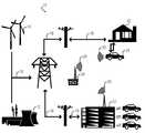
- FIG. 1is a schematic diagram of a V2G optimizing system for PHEVs according to an embodiment of the present invention
- FIG. 2is a schematic diagram of a computer system used with the V2G optimizing system in FIG. 1 showing some of the sources of data process by the computer system in accordance with an embodiment of the invention
- FIG. 3is a schematic diagram of a computer system used with the V2G optimizing system in FIG. 1 showing the various kinds of information processed by the computer system in accordance with an embodiment of the invention
- FIG. 4is a schematic diagram of a computer system used with the V2G optimizing system in FIG. 1 showing the generation of instructions in accordance with an embodiment of the invention
- FIG. 5shows a flow chart of a process for generating automated instructions shown in FIG. 4 in accordance with an embodiment of the invention.
- FIG. 6shows a high level block diagram of an information processing system useful for implementing one embodiment of the present invention.
- the present inventiongenerally provides a system for optimizing the operation of a Vehicle-to-Grid (V2G) Plugin Hybrid Electric Vehicle (PHEV).
- V2GVehicle-to-Grid
- PHEVHybrid Electric Vehicle
- the disclosed systemcan plan routes and gas/electric power utilization en-route to provide an economic benefit to the PHEV owner as well as an operator of the electric power grid.
- Embodiments of the inventionmay consider expected needs of the grid (storage or source), and the benefits to the PHEV owner for his/her contribution to the V2G system, as well as expected needs of the driver at the next driving interval. Benefits can be in monetary terms or in other quantifiable metrics such as carbon footprint.
- U.S. Pat. No. 7,013,205“System and Method for Minimizing Energy Consumption in Hybrid Vehicles”, which is incorporated herein by reference, discloses a software system for reducing energy consumption and driver costs by utilizing the electric and gasoline power sources in a PHEV to optimal advantage. This system assumes that electricity from the grid to recharge the battery at a destination is cheaper than gas to power the vehicle under most conditions.
- the system disclosed in U.S. Pat. No. 7,013,205is not a V2G system and uses the electrical grid solely as a source of power for the battery.
- a feature of the inventionis to measure the use of the battery system over the course of a given trip so that the electric/gas trade-off is optimized. For example, it may be better to use gas earlier in the trip if there is terrain later on the route that can utilize the electrical power to better efficiency and effect. Regardless of the electric/gas trade-off during the course of a driving trip, the expectation is that the traction battery in the car is mostly discharged when the vehicle is plugged into the grid and as such is simply a direct consumer of power from the grid.
- FIG. 1shows a schematic diagram of a vehicle-to-grid (V2G) optimizing system 10 for PHEVs according to an embodiment of the invention.
- V2Gvehicle-to-grid
- the basic concept of V2G poweris that, while parked, the PHEV can draw power from, or provide power to, an electric power grid.
- the system 10includes electric power generators such as those fueled by fossil fuel and nuclear power 12 , and may also include renewable energy sources 14 such as wind, solar and others.
- the electrical power generated by the power generators 12 and 14is transmitted through transmission lines 16 and through a grid 18 of electrical transmission lines to electricity users.
- the electricity usersmay include residential users 20 and commercial users 22 , each having the ability connect PHEVs 24 into the grid 18 . Electricity may flow out of the grid 18 or back to the grid 18 from PHEVs 24 , which is indicated by lines with two arrows.
- a grid operator 26such as an Independent System Operator (ISO) may send communication signals 28 to the electricity users 20 and 22 . Additional communication signals 30 back to the grid operator 26 may also be generated by the residential site 20 and the commercial site 22 , as described in more detail below. These communication signals 28 and 30 may be sent through a broadcast radio signal, a cell phone network, a direct Internet connection, a power line carrier or other communication means. In any case, during periods of peak power demand, the grid operator 26 may send signals 28 containing requests for power to a number of PHEVs 24 . Also, during periods of low power demand, the grid operator 26 may send signals 28 containing requests to store power in a number of PHEVs 24 .
- ISOIndependent System Operator
- the signals 28may go directly to each individual vehicle 24 , as shown in the residential 20 location, or to the office of a fleet operator at a commercial 22 location, which may control a number of vehicles 24 in a single parking lot. In other embodiments, the signal 28 may be sent to a third-party aggregator of dispersed individual vehicles' power (not shown).
- the PHEV 24When the PHEV 24 is operating, it may modify its operation to optimize various factors using information such as the expected needs of the grid 18 when the PHEV 24 is parked. For example, if the PHEV 24 knows that the grid will need additional electrical power during the next time that the PHEV will be parked, the PHEV 24 may modify its operation so that it will be substantially charged when it is parked. Thus, it will have available energy when needed by the grid 18 . On the other hand, if the PHEV 24 knows that the grid will need additional electrical storage capacity during the next time that the PHEV 24 will be parked, the PHEV 24 may modify its operation so that it will be substantially discharged when it is parked. Thus, it will have the storage capacity needed by the grid 18 . As described in more detail below, other considerations may also be used by the PHEV 24 , which may include the economic benefit to the driver of meeting the needs of the grid 18 , the expected needs of the driver during the next driving interval, and other considerations.
- FIG. 2shows an embodiment of a computer system used with the V2G optimizing system 10 in FIG. 1 showing some of the sources of data processed by the optimizing system 10 in accordance with an embodiment of the invention.
- the optimizing system 10includes a computer 100 that receives as inputs data 200 and instructions 300 .
- the data 200may come from various sources, such as transmitted data 201 , database data 202 , vehicle sensor data 203 , operator input data 204 , and data from other sources 209 .
- Transmitted data 201may include data from the ISO received through communication signals 28 .
- the other sourcesmay comprise, for example, predictive data determined by analysis of past data.
- FIG. 2also shows that outputs from the computer 100 may go directly to vehicle power system components 400 in the PHEV 24 , or may be presented to the operator via an in-vehicle audio and/or visual display 500 .
- the data 200is described in terms of the type of information represented by the data, such as itinerary data 210 , present location data 220 , available battery charge 230 , operational data 240 , availability of recharge facilities at, or en route to, destination 250 , current and predictive (at the time the vehicle will be attached to the grid 18 (Shown in FIG.).
- the other data 290may include any additional factors that could influence the optimizing system 10 to determine proposed routes and electric/gas trade-offs during the course of the trip.
- FIG. 3shows that outputs from the computer 100 may go directly to PHEV 24 power system components 400 or may be presented to the operator via an in-vehicle audio and/or visual display 500 .
- data category 274current and predictive needs of the grid 18
- the vehicleshould have a drained or low-level of charge in the battery at the end of the trip; but when the grid needs the vehicle as a power source, the vehicle's battery should be at a high-level of charge at the end of the trip.
- this informationcan come from either direct input from the PHEV driver, as shown at 204 , or by the optimizing system 10 (Shown in FIG. 1 ) learning driving patterns of the driver.
- the optimizing system 10can detect patterns such as “it's late evening, and the driver rarely uses the vehicle after 9:00 pm, so I can expect to be plugged into the grid for the next few hours until 7:00 am when the driver takes hisher usual trip to work”. Factors such as time of day and day of week clearly will factor into this predictive portion of the optimizing system 10 .
- the original and/or present location of PHEV 210may be obtained from transmitted data 201 , from operator input data 204 , or from other sources.
- operational data 240may be obtained from database data 202 , from operator input data 204 , or from other sources.
- available battery charge 230may be obtained from vehicle sensor data 203 , from operator input data 204 , or from other sources.
- operational data 240may be obtained from database data 202 , from operator input data 204 , or from other sources.
- availability of recharge facilities at, or en route to, destination 250may be obtained from transmitted data 201 , from database data 202 , from operator input data 204 , or from other sources.
- the cost of energy from available external electric power sources 260may be obtained from transmitted data 201 , from database data 202 , from operator input data 204 , or from other sources.
- the cost of energy from onboard consumable fuel powered means 270may be obtained from transmitted data 201 , from database data 202 , from operator input data 204 , or from other sources.
- the foregoing examplesare for the purpose of illustration and not limitation. It is possible that substantially all types of information ( FIG. 3 ) could be provided by substantially all types of data sources ( FIG. 2 ).
- FIG. 4there is shown a computer 100 receiving as inputs data 200 and instructions 300 .
- FIG. 4also shows that outputs from the computer 100 may go directly to vehicle power system components 400 or may be presented to the operator via an in-vehicle audio and/or visual display 500 .
- the instructions 300may be either operator input instructions 310 or automated instructions 320 , which are not restricted in type.
- Automated instructionsmay take the form of software, firmware, or any other form or combination of forms in which computer instructions may be automated.
- Automated instructions 320may or may not be subject to reprogramming or other change.
- An automated instruction 320would enable the computer 100 to determine, based on data 200 and potentially in conjunction other automated instructions 329 , the optimal state of charge condition to leave the PHEV 24 when parked.
- Automated instructionsmay be created by a processor that is part of computer 100 or by an external instruction generator (not shown).
- step 322An exemplary process 322 for determining an automated instruction 320 is shown in FIG. 5 .
- computer 100or an instruction generator (not shown) receives and analyzes all the needed input data 200 for the instruction, in step 323 .
- the process 322determines if the PHEV 24 will be needed as an energy source when next attached to the grid 18 , in step 324 .
- the data needed to make this determinationmay include some or all of the data 210 - 290 shown in FIG. 3 . If the answer is yes, step 331 will generate an instruction for the computer 100 (Shown in FIG. 2 ) to control the vehicle power components 400 (Shown in FIG. 3 ) such that the battery in the PHEV 24 (Shown in FIG. 1 ) will be substantially charged when is parked next.
- step 324determines that the PHEV will not be needed as an energy source by the grid 18
- step 325will determine if the PHEV will be needed for energy storage when it is expected to be parked next. If the answer is yes, then step 326 will generate an instruction to the computer 100 to control the vehicle power components 400 such that the battery in the PHEV 24 will be substantially discharged when it is expected to be parked. After steps 326 or 331 are performed the process 322 ends at step 332 .
- step 325 determinationis no, then the process 322 will generate other instructions, in step 333 .
- an alternative analysismay be performed to reach other goals, besides meeting the needs of the grid 18 . This may include operating the PHEV 24 using the combination of electric and convention on-board fuel that is most economical.
- process 322may be modified to consider other factors.
- the needs of the grid 18 and the economic benefit of meeting the needs of the grid 18may not be the only factor in determining whether the PHEV is charged or discharged when parked. These factors may be considered, but may be overridden by other considerations.
- the computer 100may compute an optimal usage profile for the vehicle's electric and conventional fuel in order to minimize the energy cost of the trip without regard for the state of the batteries when the vehicle is parked.
- the computer 100may allow the grid 18 to use the PHEV 24 as a source during the night hours, but may begin a recharging process in the early morning hours in order to restore the battery's charge by the time the PHEV 24 will be driven again.
- the determination of the computer 100could be output either directly to vehicle power system components 400 or to the in-vehicle audio and/or visual display, where it could be received by an operator who could then take appropriate action.
- operator actionmight include, but would not be limited to, an operator input instruction 310 (shown in FIG. 4 ) to cause the computer 100 to generate an output to, for example, determine optimal energy usage profile directly to the vehicle power system components 400 .
- origin and location datacould be provided by operator input, by GPS transmission, or by other sources.
- Available battery charge datacould be provided by operator input, by vehicle sensors, or by other sources.
- Operational datacould be provided by operator input, by database, or by other sources.
- a database of operational datacould be compiled automatically as data is collected in the ordinary course of operation of the invention; alternatively, such a database could be compiled from vehicle performance specification data or from other sources.
- Data as to the availability of recharge facilities at, or en route to, the destinationcould be provided by transmission, by database, by operator input, or by other sources.
- Data as to the availability of recharge facilities at, or en route to, the destinationcould be provided as GPS data used in conjunction with a database of facility locations, or provided directly by recharging facilities transmitting such location data to notify drivers en route.
- the computer 100is located away from the vehicle and connected to the vehicle by wireless network or other means, notification of the availability of recharge facilities at, or en route to, the destination could be provided to the computer by other sources.
- some embodiments of the inventionwould be capable of receiving data as to the availability of recharge facilities at, or en route to, the destination and adjusting the vehicle's optimization plan accordingly, which may include a determination of an optimum route as well as an optimum gas/electric power utilization.
- Such adjustmentscould be calculated on the fly, according to automated instructions, with notification to the operator of the location of the recharging facility and of the energy cost savings if a recharging stop were made and the calculated adjustment were implemented. The operator could then input an instruction to accept or reject the adjustment.
- Data as to the cost of energy from available external electric power sourcescould be provided by communication signals 28 , by database, by operator input, or by other sources.
- transmitted data as to the cost of energy from recharging facilities at, or en route to, the destinationsuch data could be provided directly by recharging facilities transmitting the data to notify drivers en route.
- the computeris located away from the vehicle and connected to the vehicle by wireless network or other means, notification of the cost of energy from available external electric power sources at, or en route to, the destination could be provided by other sources.
- some embodiments of the inventionwould be capable of receiving notification and adjusting the vehicle's refueling plan and the management of the consumption ratio between electric charge and consumable fuel so that consumption of consumable fuel may be optimized for cost-effectiveness, while balancing the needs of the grid 18 and the benefits of meeting those needs.
- Such adjustmentscould be calculated on the fly, according to automated instructions, with notification to the operator of the location of the recharging facility and of the energy cost savings if a recharging stop were made and the calculated change in management of the consumption ratio were implemented. The operator could then input an instruction to accept or reject the adjustment.
- the optimization system 10may employ various types of a communication medium and infrastructure, e.g., wireless or cell phone, in order for the PHEV 24 to communicate real-time with the grid 18 while driving.
- This communicationmay be used to gather the current and predictive information from the grid 18 about the expected requirements and benefits of the PHEV 24 in the V2G connection.
- this communication mediumor an alternative such as landline based network, could be used while the vehicle is connected to the grid to communicate any real-time and expected requirements of the driver and/or the grid.
- Data as to the cost of energy from onboard consumable fuel powered meanscould be provided by database, by operator input, or by other sources.
- Other data determined to be useful in any embodiment of the inventioncould be provided, as appropriate, by transmission, by database, by vehicle sensor, by operator input, or by other sources.
- some embodiments of the inventionmay locate the computer onboard the hybrid vehicle, while other embodiments may provide for the hybrid vehicle to be connected by wireless network or other means to a computer (including, but not limited to, a server) located somewhere else.
- Some embodiments of the inventionmay locate data sources (including, but not limited to, storage devices or databases) onboard the hybrid vehicle, while other embodiments may provide for the hybrid vehicle to be connected by wireless network or other means to one or more data sources (including, but not limited to, storage devices or databases) located somewhere else.
- the PHEV 24may also be equipped with a passive recharging system, such as a regenerative braking system.
- the computer 100may also consider the availability of recharging using such passive means when controlling the power system components 400 . For example, if the PHEV 24 has regenerative braking, an important factor for the computer 100 may be the amount of stop-and-go driving versus non-stop highway travel, since these conditions will affect the amount of potential recharging using regenerative braking.
- the inventioncan take the form of an entirely hardware embodiment, an entirely software embodiment, or an embodiment containing both hardware and software elements.
- the inventionis implemented in software, which includes, but is not limited to, firmware, resident software, and microcode.
- the inventioncan take the form of a computer program product accessible from a computer-usable or computer-readable medium providing program code for use by, or in connection with, a computer or any instruction execution system.
- a computer-usable or computer-readable mediumcan be any apparatus that can contain, store, communicate, propagate, or transport the program for use by, or in connection with, the instruction execution system, apparatus, or device.
- the mediumcan be an electronic, magnetic, optical, electromagnetic, infrared, semiconductor system (or apparatus or device), or a propagation medium.
- Examples of a computer-readable mediuminclude a semiconductor or solid state memory, magnetic tape, a removable computer diskette, a random access memory (RAM), a read-only memory (ROM), a rigid magnetic disk, or an optical disk.
- Current examples of optical disksinclude compact disk-read-only memory (CD-ROM), compact disk-read/write (CD-RW), and DVD.
- a data processing system suitable for storing and/or executing program codewill include at least one processor coupled directly or indirectly to memory elements through a system bus.
- the memory elementscan include local memory employed during actual execution of the program code, bulk storage, and cache memories which provide temporary storage of at least some program code in order to reduce the number of times code must be retrieved from bulk storage during execution.
- I/O devicesincluding, but not limited to, keyboards, displays, pointing devices
- I/O controllerscan be coupled to the system either directly or through intervening I/O controllers.
- Network adaptersmay also be coupled to the system to enable the data processing system to become coupled to other data processing systems or remote printers or storage devices through intervening private or public networks.
- Modems, cable modems, and Ethernet cardsare just a few of the currently available types of network adapters.
- FIG. 6is a high level block diagram showing an information processing system useful for implementing one embodiment of the present invention.
- the computer systemincludes one or more processors, such as processor 502 .
- the processor 502is connected to a communication infrastructure 504 (e.g., a communications bus, cross-over bar, or network).
- a communication infrastructure 504e.g., a communications bus, cross-over bar, or network.
- the computer systemcan include a display interface 506 that forwards graphics, text, and other data from the communication infrastructure 504 (or from a frame buffer not shown) for display on a display unit 508 .
- the computer systemalso includes a main memory 510 , preferably random access memory (RAM), and may also include a secondary memory 512 .
- the secondary memory 512may include, for example, a hard disk drive 514 and/or a removable storage drive 516 , representing, for example, a floppy disk drive, a magnetic tape drive, or an optical disk drive.
- the removable storage drive 516reads from and/or writes to a removable storage unit 518 in a manner well known to those having ordinary skill in the art.
- Removable storage unit 518represents, for example, a floppy disk, a compact disc, a magnetic tape, flash memory card, or an optical disk, etc., which is read and written to by removable storage drive 516 .
- the removable storage unit 518includes a computer readable medium having stored therein computer software and/or data.
- the secondary memory 512may include other similar means for allowing computer programs or other instructions to be loaded into the computer system.
- Such meansmay include, for example, a removable storage unit 520 and an interface 522 .
- Examples of such meansmay include a program cartridge and cartridge interface (such as that found in video game devices), a removable memory chip (such as an EPROM, or PROM) and associated socket, and other removable storage units 520 and interfaces 522 which allow software and data to be transferred from the removable storage unit 520 to the computer system.
- the computer systemmay also include a communications interface 524 .
- Communications interface 524allows software and data to be transferred between the computer system and external devices. Examples of communications interface 524 may include a modem, a network interface (such as an Ethernet card), a communications port, or a PCMCIA slot and card, etc.
- Software and data transferred via communications interface 524are in the form of signals which may be, for example, electronic, electromagnetic, optical, or other signals capable of being received by communications interface 524 . These signals are provided to communications interface 524 via a communications path (i.e., channel) 526 .
- This channel 526carries signals and may be implemented using wire or cable, fiber optics, a phone line, a cellular phone link, an RF link, wifi and/or other communications channels.
- computer program medium“computer usable medium,” and “computer readable medium” are used to generally refer to media such as main memory 510 and secondary memory 512 , removable storage drive 516 , and a hard disk installed in hard disk drive 514 .
- Computer programsare stored in main memory 510 and/or secondary memory 512 . Computer programs may also be received via communications interface 524 . Such computer programs, when executed, enable the computer system to perform the features of the present invention as discussed herein. In particular, the computer programs, when executed, enable the processor 502 to perform the features of the computer system. Accordingly, such computer programs represent controllers of the computer system.
- the present inventionprovides a system, computer program product, and method for optimizing a V2G system.
- embodiments of the inventionmay take into consideration expected grid needs (storage or source), and the economic benefit to the driver for hisher contribution to the V2G system, as well as expected needs of the driver at the next driving interval. Economic benefit can be in monetary terms, or in other quantifiable metrics such as carbon footprint.
Landscapes
- Engineering & Computer Science (AREA)
- Transportation (AREA)
- Mechanical Engineering (AREA)
- Power Engineering (AREA)
- Automation & Control Theory (AREA)
- Life Sciences & Earth Sciences (AREA)
- Sustainable Development (AREA)
- Sustainable Energy (AREA)
- Chemical & Material Sciences (AREA)
- Combustion & Propulsion (AREA)
- Human Computer Interaction (AREA)
- Electric Propulsion And Braking For Vehicles (AREA)
Abstract
Description
Claims (18)
Priority Applications (1)
| Application Number | Priority Date | Filing Date | Title |
|---|---|---|---|
| US12/048,183US7928693B2 (en) | 2008-03-13 | 2008-03-13 | Plugin hybrid electric vehicle with V2G optimization system |
Applications Claiming Priority (1)
| Application Number | Priority Date | Filing Date | Title |
|---|---|---|---|
| US12/048,183US7928693B2 (en) | 2008-03-13 | 2008-03-13 | Plugin hybrid electric vehicle with V2G optimization system |
Publications (2)
| Publication Number | Publication Date |
|---|---|
| US20090229900A1 US20090229900A1 (en) | 2009-09-17 |
| US7928693B2true US7928693B2 (en) | 2011-04-19 |
Family
ID=41061787
Family Applications (1)
| Application Number | Title | Priority Date | Filing Date |
|---|---|---|---|
| US12/048,183Active2029-03-24US7928693B2 (en) | 2008-03-13 | 2008-03-13 | Plugin hybrid electric vehicle with V2G optimization system |
Country Status (1)
| Country | Link |
|---|---|
| US (1) | US7928693B2 (en) |
Cited By (21)
| Publication number | Priority date | Publication date | Assignee | Title |
|---|---|---|---|---|
| US20090288896A1 (en)* | 2007-02-20 | 2009-11-26 | Toyota Jidosha Kabushiki Kaisha | Hybrid vehicle |
| US20100188043A1 (en)* | 2009-01-29 | 2010-07-29 | Tesla Motors, Inc. | System for optimizing battery pack cut-off voltage |
| US20100256846A1 (en)* | 2009-04-07 | 2010-10-07 | Cisco Technology, Inc. | System and method for managing electric vehicle travel |
| US20120153896A1 (en)* | 2008-12-15 | 2012-06-21 | Comverge, Inc. | Method and system for co-operative charging of electric vehicles |
| US20120245762A1 (en)* | 2009-08-25 | 2012-09-27 | Jochen Fassnacht | Method and device for operating a hybrid drive of a vehicle |
| US20120249065A1 (en)* | 2011-04-01 | 2012-10-04 | Michael Bissonette | Multi-use energy management and conversion system including electric vehicle charging |
| US20120286573A1 (en)* | 2011-05-11 | 2012-11-15 | Disco Corporation | Power managing system |
| WO2013003344A3 (en)* | 2011-06-27 | 2013-03-14 | Bloom Energy Corporation | Electric vehicle charging using fuel cell system |
| US8725330B2 (en) | 2010-06-02 | 2014-05-13 | Bryan Marc Failing | Increasing vehicle security |
| US9121710B2 (en) | 2013-03-13 | 2015-09-01 | Ford Global Technologies, Llc | User interface system and method based on calendar event |
| US9630511B2 (en) | 2014-03-05 | 2017-04-25 | Nissan North America, Inc. | Vehicle-to-grid system with power loss compensation |
| US9709969B2 (en) | 2013-03-15 | 2017-07-18 | Deere & Company | Methods and apparatus to control machine configurations |
| US20170203655A1 (en)* | 2016-01-19 | 2017-07-20 | Ford Global Technologies, Llc | Controlling operation of electrified vehicle travelling on inductive roadway to influence electrical grid |
| EP3741612A1 (en)* | 2019-05-21 | 2020-11-25 | Rolls-Royce plc | Forecast of electric vehicle state of charge and energy storage capacity |
| US11077766B2 (en) | 2018-08-30 | 2021-08-03 | Honda Motor Co., Ltd. | Vehicle-to-grid energy for use with hydrogen generation |
| US11127056B2 (en) | 2017-11-30 | 2021-09-21 | Honda Motor Co., Ltd. | System and method for determining at least one demand response overhead percentage |
| US11345251B2 (en) | 2020-06-23 | 2022-05-31 | Toyota Motor North America, Inc. | Priority-based energy transfer |
| US11571984B2 (en) | 2020-04-21 | 2023-02-07 | Toyota Motor North America, Inc. | Load effects on transport energy |
| US11760223B2 (en) | 2020-06-23 | 2023-09-19 | Toyota Motor North America, Inc. | Need-based energy sharing |
| US11897358B2 (en) | 2021-11-23 | 2024-02-13 | Honda Motor Co., Ltd. | Renewable energy credit management system and method for use with electric vehicles |
| US12128785B2 (en) | 2020-04-21 | 2024-10-29 | Toyota Motor North America, Inc. | Transport charge offload management |
Families Citing this family (93)
| Publication number | Priority date | Publication date | Assignee | Title |
|---|---|---|---|---|
| US7277782B2 (en)* | 2001-01-31 | 2007-10-02 | Oshkosh Truck Corporation | Control system and method for electric vehicle |
| US7956570B2 (en)* | 2008-01-07 | 2011-06-07 | Coulomb Technologies, Inc. | Network-controlled charging system for electric vehicles |
| US7952319B2 (en)* | 2008-01-07 | 2011-05-31 | Coulomb Technologies, Inc. | Street light mounted network-controlled charge transfer device for electric vehicles |
| US20090177580A1 (en)* | 2008-01-07 | 2009-07-09 | Lowenthal Richard W | Collection of electric vehicle power consumption tax |
| US8116915B2 (en)* | 2008-03-03 | 2012-02-14 | University Of Delaware | Methods and apparatus using hierarchical priority and control algorithms for grid-integrated vehicles |
| US20110270476A1 (en)* | 2008-07-08 | 2011-11-03 | Siemens Aktiengesellschaft | Adapter device and method for charging a vehicle |
| WO2010022059A1 (en) | 2008-08-18 | 2010-02-25 | Austin Christopher B | Vehicular battery charger, charging system, and method |
| JP4713623B2 (en)* | 2008-09-25 | 2011-06-29 | 株式会社日立製作所 | Charge / discharge management device |
| US8421592B1 (en)* | 2008-10-15 | 2013-04-16 | Sprint Communications Company L.P. | Mediation of electric vehicle charging by wireless network provider |
| US8024082B2 (en)* | 2009-03-11 | 2011-09-20 | General Electric Company | System and method for optimizing energy storage component usage |
| US20100280686A1 (en)* | 2009-04-30 | 2010-11-04 | Searete Llc, A Limited Liability Corporation Of The State Of Delaware | Awarding privileges to a vehicle based upon one or more fuel utilization characteristics |
| US20100280707A1 (en)* | 2009-04-30 | 2010-11-04 | Searete Llc, A Limited Liability Corporation Of State Of Delaware | Awarding standings to a vehicle based upon one or more fuel utilization characteristics |
| US20100280688A1 (en)* | 2009-04-30 | 2010-11-04 | Searete Llc, A Limited Liability Corporation Of The State Of Delaware | Awarding standings to a vehicle based upon one or more fuel utilization characteristics |
| US20100280691A1 (en)* | 2009-04-30 | 2010-11-04 | Searete Llc, A Limited Liability Corporation Of The State Of Delaware | Awarding standings to a vehicle based upon one or more fuel utilization characteristics |
| US20100280689A1 (en)* | 2009-04-30 | 2010-11-04 | Searete Llc, A Limited Liability Corporation Of The State Of Delaware | Awarding standings to a vehicle based upon one or more fuel utilization characteristics |
| US20100280888A1 (en)* | 2009-04-30 | 2010-11-04 | Searete LLC, a limited libaility corporation of the State of Delaware | Awarding privileges to a vehicle based upon one or more fuel utilization characteristics |
| US20110106354A1 (en)* | 2009-04-30 | 2011-05-05 | Searete Llc, A Limited Liability Corporation Of The State Of Delaware | Awarding standings to a vehicle based upon one or more fuel utilization characteristics |
| US20100280706A1 (en)* | 2009-04-30 | 2010-11-04 | Searete Llc, A Limited Liability Corporation Of State Of Delaware | Awarding standings to a vehicle based upon one or more fuel utilization characteristics |
| US20100280709A1 (en)* | 2009-04-30 | 2010-11-04 | Searete Llc, A Limited Liability Corporation Of The State Of Delaware | Awarding standings to a vehicle based upon one or more fuel utilization characteristics |
| US20100280705A1 (en)* | 2009-04-30 | 2010-11-04 | Searete Llc, A Limited Liability Corporation Of The State Of Delaware | Awarding standings to a vehicle based upon one or more fuel utilization characteristics |
| US20100280886A1 (en)* | 2009-04-30 | 2010-11-04 | Searete Llc, A Limited Liability Corporation Of The State Of Delware | Awarding privileges to a vehicle based upon one or more fuel utilization characteristics |
| US20100280887A1 (en)* | 2009-04-30 | 2010-11-04 | Searete Llc, A Limited Liability Corporation Of The State Of Delaware | Awarding privileges to a vehicle based upon one or more fuel utilization characteristics |
| US20100280690A1 (en)* | 2009-04-30 | 2010-11-04 | Searete Llc, A Limited Liability Corporation Of The State Of Delaware | Awarding standings to a vehicle based upon one or more fuel utilization characteristics |
| US20100280692A1 (en)* | 2009-04-30 | 2010-11-04 | Searete Llc, A Limited Liability Corporation Of The State Of Delaware | Awarding standings to a vehicle based upon one or more fuel utilization characteristics |
| US8855907B2 (en)* | 2009-04-30 | 2014-10-07 | Searete Llc | Awarding privileges to a vehicle based upon one or more fuel utilization characteristics |
| US20100280885A1 (en)* | 2009-04-30 | 2010-11-04 | Searete Llc, A Limited Liability Corporation Of The State Of Delaware | Awarding privileges to a vehicle based upon one or more fuel utilization characteristics |
| DE102009041409A1 (en)* | 2009-09-16 | 2011-03-24 | Georg, Erich W., Dr. | Method for charging a battery pack |
| EP2481140A4 (en)* | 2009-09-25 | 2017-10-18 | LG Electronics Inc. | Apparatus and method for controlling a battery |
| US8781637B2 (en)* | 2009-10-27 | 2014-07-15 | Voltserver Inc. | Safe exposed conductor power distribution system |
| US20110184587A1 (en)* | 2010-01-25 | 2011-07-28 | Flux Engineering, LLC. | System and Method for Trading Electrical or Other Portable Power or Energy Source |
| US9299093B2 (en)* | 2010-01-29 | 2016-03-29 | GM Global Technology Operations LLC | Method for charging a plug-in electric vehicle |
| US20110196692A1 (en)* | 2010-02-09 | 2011-08-11 | Chavez Jr Lloyd G | Apparatus, system and method for grid storage |
| US9043038B2 (en)* | 2010-02-18 | 2015-05-26 | University Of Delaware | Aggregation server for grid-integrated vehicles |
| DE102010027729A1 (en)* | 2010-04-14 | 2011-10-20 | Bayerische Motoren Werke Aktiengesellschaft | Method for an electrically driven vehicle, electrically powered vehicle and system of an electrically driven vehicle and an off-vehicle unit |
| DE102010027793A1 (en)* | 2010-04-15 | 2011-10-20 | Robert Bosch Gmbh | Method and device for determining an excess amount of energy of an electrical energy storage device of a vehicle |
| KR100963529B1 (en) | 2010-04-22 | 2010-06-15 | 한국에너지기술연구원 | Electric station and charging system with fuel cell system and control method thereof |
| US20110276194A1 (en)* | 2010-05-10 | 2011-11-10 | Emalfarb Hal A | System and method for energy management |
| DE102010029934A1 (en)* | 2010-06-10 | 2011-12-15 | Bayerische Motoren Werke Aktiengesellschaft | Method for monitoring the operating state of a vehicle, in particular an electric or hybrid vehicle |
| WO2011156776A2 (en)* | 2010-06-10 | 2011-12-15 | The Regents Of The University Of California | Smart electric vehicle (ev) charging and grid integration apparatus and methods |
| US9091559B2 (en) | 2010-06-17 | 2015-07-28 | International Business Machines Corporation | Managing electrical power utilization in an electric vehicle |
| FI20105791L (en)* | 2010-07-12 | 2012-01-13 | Fortel Components Oy | Island CHP plant using wood chips |
| WO2012017936A1 (en)* | 2010-08-05 | 2012-02-09 | 三菱自動車工業株式会社 | Battery information output device for power supply/demand leveling system |
| US9340117B2 (en)* | 2010-08-05 | 2016-05-17 | Mitsubishi Jidosha Kogyo Kabushiki Kaisha | Power supply and demand leveling system |
| CN102386665A (en)* | 2010-08-31 | 2012-03-21 | 湖南大学 | Electric vehicle charging device intelligently responding to voltage level of power grid |
| JP2012060834A (en) | 2010-09-10 | 2012-03-22 | Panasonic Electric Works Co Ltd | Charge control device |
| MX2013003209A (en)* | 2010-09-21 | 2013-06-03 | Proterra Inc | Systems and methods for equivalent rapid charging with different energy storage configurations. |
| CN102437584A (en)* | 2010-10-27 | 2012-05-02 | 上海市电力公司 | System and method for applying electric vehicle as mobile energy storage device in smart power grid |
| DE102010043001A1 (en)* | 2010-10-27 | 2012-05-03 | Siemens Aktiengesellschaft | Charging system and method for charging vehicle batteries |
| KR101746177B1 (en) | 2010-12-23 | 2017-06-27 | 한국전자통신연구원 | Charging method and apparatus for electric vehicle |
| US20120239594A1 (en)* | 2011-03-17 | 2012-09-20 | John Christopher Boot | Apparatus and methods for providing demand response information |
| CN102324752B (en)* | 2011-06-17 | 2013-11-13 | 辽宁省电力有限公司 | Wind power generation-combined ordered charge and discharge coordinated control system of pure electric vehicle |
| KR101782555B1 (en) | 2011-06-30 | 2017-09-28 | 한국전자통신연구원 | System for managing battery charge of electric vehicle and method thereof |
| JP2013030973A (en)* | 2011-07-28 | 2013-02-07 | Nippon Soken Inc | Power supply device, contactless power transmission device, vehicle, and contactless power transmission system |
| US8326467B2 (en)* | 2011-09-06 | 2012-12-04 | General Electric Company | Controller and method of controlling a power system |
| US9620970B2 (en) | 2011-11-30 | 2017-04-11 | The Regents Of The University Of California | Network based management for multiplexed electric vehicle charging |
| CN102624015A (en)* | 2012-01-12 | 2012-08-01 | 清华大学 | A control device for the mutual exchange of electric vehicle electric energy and residential electric energy |
| JP5872298B2 (en)* | 2012-01-13 | 2016-03-01 | 株式会社日立製作所 | Power supply system and automobile control device capable of supplying power to outside |
| CN102593915A (en)* | 2012-03-06 | 2012-07-18 | 郭春林 | Equipment and method for carrying out valley period charging |
| CN102593914A (en)* | 2012-03-06 | 2012-07-18 | 华北电力大学 | Equipment and method for carrying out timed charging |
| US20150127203A1 (en)* | 2012-05-15 | 2015-05-07 | Toyota Jidosha Kabushiki Kaisha | Vehicle travel control assistance device |
| US9296309B2 (en) | 2012-09-12 | 2016-03-29 | Ford Global Technologies, Llc | Customized battery charging |
| CN103595107B (en)* | 2013-12-02 | 2015-11-11 | 国家电网公司 | Electric automobile charge-discharge control system and method |
| CN103825337B (en)* | 2014-03-12 | 2015-09-16 | 上海理工大学 | Based on V2G Constant-current discharge system and control method thereof |
| US9121722B1 (en)* | 2014-03-19 | 2015-09-01 | Ford Global Technologies, Llc | Trip partitioning based on driving pattern energy consumption |
| CN103840457B (en)* | 2014-03-20 | 2016-03-09 | 上海电力学院 | Consider DG Optimal Configuration Method in the power distribution network that electric automobile discharge and recharge affects |
| US9187085B1 (en)* | 2014-04-24 | 2015-11-17 | Ford Global Technologies, Llc | Electric vehicle control based on operating costs associated with power sources |
| EP3212457B1 (en)* | 2014-10-30 | 2022-05-11 | Google LLC | Mediator device for smart electric vehicle charging |
| JP6623522B2 (en)* | 2015-01-26 | 2019-12-25 | セイコーエプソン株式会社 | Robots, robot systems and servers |
| US9630518B2 (en)* | 2015-06-09 | 2017-04-25 | Ford Global Technologies, Llc | Dynamic grid loading using plug-in electrified vehicles |
| CN105356459A (en)* | 2015-11-23 | 2016-02-24 | 东南大学 | A control method for allowing electric automobiles to participate in power system frequency modulation in a scattered grid-access manner |
| US10164433B2 (en)* | 2016-01-19 | 2018-12-25 | Ford Global Technologies, Llc | Adjusting electrified vehicle operation to balance electrical grid |
| JP6512151B2 (en)* | 2016-03-30 | 2019-05-15 | トヨタ自動車株式会社 | Hybrid car |
| JP2017178082A (en)* | 2016-03-30 | 2017-10-05 | トヨタ自動車株式会社 | Hybrid motorcar |
| CN105811444B (en)* | 2016-04-26 | 2018-08-14 | 海南电网有限责任公司 | A kind of electric vehicle and power grid interactive simulation load system and its electrical protection method |
| JP6321763B1 (en)* | 2016-12-02 | 2018-05-09 | 本田技研工業株式会社 | Power storage system, transportation device, and control method of power storage system |
| CN106740221B (en)* | 2017-01-06 | 2020-12-29 | 中国计量大学 | A V2G wireless power bidirectional transmission device based on low frequency PWM rectifier |
| KR20180121105A (en)* | 2017-04-28 | 2018-11-07 | 현대자동차주식회사 | Apparatus and method for charging and discharging electric vehcile under smart grid environment |
| GB2567419B (en)* | 2017-09-28 | 2022-05-18 | Detroit Electric Ev Ltd | Home charging and power backup unit |
| CN109353243B (en)* | 2018-11-13 | 2021-11-09 | 国网电动汽车(山西)服务有限公司 | Discharging algorithm for realizing bidirectional ordered charging and discharging of intelligent charging pile system |
| CN109398149B (en)* | 2018-11-29 | 2022-03-22 | 江苏大学 | Intelligent electric vehicle charging and discharging system based on distributed energy application and operation control method thereof |
| CN109927582B (en)* | 2018-12-29 | 2020-11-24 | 西安盈胜电气科技有限公司 | Charging pile system based on Internet of things technology and bidirectional ordered charging and discharging method |
| US12046905B2 (en) | 2019-03-28 | 2024-07-23 | Nuvve Corporation | Multi-technology grid regulation service |
| CN110303931B (en)* | 2019-05-29 | 2021-03-23 | 北京航盛新能科技有限公司 | Electric automobile intelligent charging method suitable for V2G |
| CN112193121B (en)* | 2020-12-04 | 2021-03-02 | 国网智慧能源交通技术创新中心(苏州)有限公司 | A cluster discharge control method for V2G DC charging piles |
| US11987144B2 (en)* | 2021-01-13 | 2024-05-21 | Toyota Motor North America, Inc. | Transport energy transfer using real-time cost information |
| US11623540B2 (en) | 2021-01-13 | 2023-04-11 | Toyota Motor North America, Inc. | Transport recharge level determination |
| JP2022109168A (en)* | 2021-01-14 | 2022-07-27 | トヨタ自動車株式会社 | Charge/discharge controller |
| CN113067370B (en)* | 2021-03-15 | 2023-07-18 | 远景智能国际私人投资有限公司 | Charging control method, device, server and storage medium of V2G charging station |
| JP7604970B2 (en)* | 2021-03-22 | 2024-12-24 | トヨタ自動車株式会社 | SOC adjustment device and SOC adjustment method |
| US20220383429A1 (en) | 2021-06-01 | 2022-12-01 | Nuvve Corporation | Virtualized battery resources for grid service participation |
| US11747781B1 (en) | 2022-03-21 | 2023-09-05 | Nuvve Corporation | Intelligent local energy management system at local mixed power generating sites for providing grid services |
| US11695274B1 (en) | 2022-03-21 | 2023-07-04 | Nuvve Corporation | Aggregation platform for intelligent local energy management system |
| CN114784833A (en)* | 2022-04-28 | 2022-07-22 | 度普(苏州)新能源科技有限公司 | Method, device and energy storage charging pile for energy storage charging pile to reverse energy supply to power grid |
Citations (12)
| Publication number | Priority date | Publication date | Assignee | Title |
|---|---|---|---|---|
| US5642270A (en)* | 1991-08-01 | 1997-06-24 | Wavedriver Limited | Battery powered electric vehicle and electrical supply system |
| US6434465B2 (en) | 1999-12-28 | 2002-08-13 | Robert Bosch Gmbh | Method for controlling/regulating a process in a motor vehicle and device for implementing the method |
| US6487477B1 (en) | 2001-05-09 | 2002-11-26 | Ford Global Technologies, Inc. | Strategy to use an on-board navigation system for electric and hybrid electric vehicle energy management |
| US20040062059A1 (en) | 2002-07-19 | 2004-04-01 | Ballard Power Systems Corporation | Apparatus and method employing bi-directional converter for charging and/or supplying power |
| US7013205B1 (en) | 2004-11-22 | 2006-03-14 | International Business Machines Corporation | System and method for minimizing energy consumption in hybrid vehicles |
| US20070068714A1 (en) | 2005-09-23 | 2007-03-29 | Afs Trinity Power Corporation | Method and apparatus for power electronics and control of plug-in hybrid propulsion with fast energy storage |
| US7216729B2 (en) | 2003-09-19 | 2007-05-15 | Ford Global Technologies, Llc | Method and system of requesting engine on/off state in a hybrid electric vehicle |
| US20070282495A1 (en) | 2006-05-11 | 2007-12-06 | University Of Delaware | System and method for assessing vehicle to grid (v2g) integration |
| US7309966B2 (en)* | 2003-07-09 | 2007-12-18 | Aloys Wobben | Motor vehicle |
| US20080039989A1 (en)* | 2006-08-10 | 2008-02-14 | V2 Green, Inc. | User Interface and User Control in a Power Aggregation System for Distributed Electric Resources |
| US20080312782A1 (en)* | 2007-06-15 | 2008-12-18 | Gene Berdichevsky | Electric vehicle communication interface |
| US20090192655A1 (en)* | 2006-08-25 | 2009-07-30 | Toyota Jidosha Kabushiki Kaisha | Power System |
- 2008
- 2008-03-13USUS12/048,183patent/US7928693B2/enactiveActive
Patent Citations (13)
| Publication number | Priority date | Publication date | Assignee | Title |
|---|---|---|---|---|
| US5642270A (en)* | 1991-08-01 | 1997-06-24 | Wavedriver Limited | Battery powered electric vehicle and electrical supply system |
| US6434465B2 (en) | 1999-12-28 | 2002-08-13 | Robert Bosch Gmbh | Method for controlling/regulating a process in a motor vehicle and device for implementing the method |
| US6487477B1 (en) | 2001-05-09 | 2002-11-26 | Ford Global Technologies, Inc. | Strategy to use an on-board navigation system for electric and hybrid electric vehicle energy management |
| US20040062059A1 (en) | 2002-07-19 | 2004-04-01 | Ballard Power Systems Corporation | Apparatus and method employing bi-directional converter for charging and/or supplying power |
| US7309966B2 (en)* | 2003-07-09 | 2007-12-18 | Aloys Wobben | Motor vehicle |
| US7216729B2 (en) | 2003-09-19 | 2007-05-15 | Ford Global Technologies, Llc | Method and system of requesting engine on/off state in a hybrid electric vehicle |
| US7013205B1 (en) | 2004-11-22 | 2006-03-14 | International Business Machines Corporation | System and method for minimizing energy consumption in hybrid vehicles |
| US20070068714A1 (en) | 2005-09-23 | 2007-03-29 | Afs Trinity Power Corporation | Method and apparatus for power electronics and control of plug-in hybrid propulsion with fast energy storage |
| US20070282495A1 (en) | 2006-05-11 | 2007-12-06 | University Of Delaware | System and method for assessing vehicle to grid (v2g) integration |
| US20080039989A1 (en)* | 2006-08-10 | 2008-02-14 | V2 Green, Inc. | User Interface and User Control in a Power Aggregation System for Distributed Electric Resources |
| US20090192655A1 (en)* | 2006-08-25 | 2009-07-30 | Toyota Jidosha Kabushiki Kaisha | Power System |
| US20080312782A1 (en)* | 2007-06-15 | 2008-12-18 | Gene Berdichevsky | Electric vehicle communication interface |
| US7698078B2 (en)* | 2007-06-15 | 2010-04-13 | Tesla Motors, Inc. | Electric vehicle communication interface |
Non-Patent Citations (10)
| Title |
|---|
| Boujelelben et al., IEEE 2006 0-7803-9794-0/06 Evaluation and optimization of a hybrid urban Microbus. |
| Cikanek et al., Ford Research Laboratory Proceedings of the American Control Conference San Diego Jun. 1999 Control System and Dynamic Model Validation for a Parallel Hybrid Electric Vehicle. |
| Gonder et al.,NREL/CP-540-40970 2007 SAE World Congress Apr. 16-19, 2007 Detroit Michigan Energy Management Strategies for Plug-in Hybrid Electric Vehicles. |
| Markel et al., Advanced Automotive Battery Conference May 19, 2006 Plug-in Hybrid Electric Vehicle Energy Storage System Design. |
| O'Keefe et al.,NREL/CP-540-40376 Conference Paper Nov. 2006 Dynamic Programming Applied to Investigate Energy Management Strategies for a Plug-in HEV. |
| Piccolo et al., Universita' Degli Studi-Salerno [Abstract only] Fuzzy Logic Based Optimal Power Flow Management in Parallel Hybrid Electrical Vehicles. |
| Piccolo et al., Universita' Degli Studi—Salerno [Abstract only] Fuzzy Logic Based Optimal Power Flow Management in Parallel Hybrid Electrical Vehicles. |
| S. De Breucker et al., Dep. Electrical Engineering Research Group Electa Kasteelpark Arenberg 10 Belgium Grid Power Quality Improvements Using Grid-Coupled Hybrid Electric Vehicles PEMD 2006. |
| Short et al., NREL/TP-620-39729 Apr. 2006 A preliminary Assessment of Plug-in Hybrid Electric Vehicles on Wind Energy Markets. |
| Zhonghao et al., Hunan University China College of Electrical Information Engineering Research on Modeling and Simulation of Hybrid Electric Vehicle Energy Control Systems. |
Cited By (39)
| Publication number | Priority date | Publication date | Assignee | Title |
|---|---|---|---|---|
| US20090288896A1 (en)* | 2007-02-20 | 2009-11-26 | Toyota Jidosha Kabushiki Kaisha | Hybrid vehicle |
| US8256547B2 (en)* | 2007-02-20 | 2012-09-04 | Toyota Jidosha Kabushiki Kaisha | Hybrid vehicle |
| US20120153896A1 (en)* | 2008-12-15 | 2012-06-21 | Comverge, Inc. | Method and system for co-operative charging of electric vehicles |
| US8963492B2 (en)* | 2008-12-15 | 2015-02-24 | Comverge, Inc. | Method and system for co-operative charging of electric vehicles |
| US20100188043A1 (en)* | 2009-01-29 | 2010-07-29 | Tesla Motors, Inc. | System for optimizing battery pack cut-off voltage |
| US8054038B2 (en)* | 2009-01-29 | 2011-11-08 | Tesla Motors, Inc. | System for optimizing battery pack cut-off voltage |
| US20100256846A1 (en)* | 2009-04-07 | 2010-10-07 | Cisco Technology, Inc. | System and method for managing electric vehicle travel |
| US8457821B2 (en)* | 2009-04-07 | 2013-06-04 | Cisco Technology, Inc. | System and method for managing electric vehicle travel |
| US20120245762A1 (en)* | 2009-08-25 | 2012-09-27 | Jochen Fassnacht | Method and device for operating a hybrid drive of a vehicle |
| US8841881B2 (en) | 2010-06-02 | 2014-09-23 | Bryan Marc Failing | Energy transfer with vehicles |
| US8725330B2 (en) | 2010-06-02 | 2014-05-13 | Bryan Marc Failing | Increasing vehicle security |
| US10124691B1 (en) | 2010-06-02 | 2018-11-13 | Bryan Marc Failing | Energy transfer with vehicles |
| US9114719B1 (en) | 2010-06-02 | 2015-08-25 | Bryan Marc Failing | Increasing vehicle security |
| US11186192B1 (en) | 2010-06-02 | 2021-11-30 | Bryan Marc Failing | Improving energy transfer with vehicles |
| US9393878B1 (en) | 2010-06-02 | 2016-07-19 | Bryan Marc Failing | Energy transfer with vehicles |
| US20120249065A1 (en)* | 2011-04-01 | 2012-10-04 | Michael Bissonette | Multi-use energy management and conversion system including electric vehicle charging |
| US20120286573A1 (en)* | 2011-05-11 | 2012-11-15 | Disco Corporation | Power managing system |
| WO2013003344A3 (en)* | 2011-06-27 | 2013-03-14 | Bloom Energy Corporation | Electric vehicle charging using fuel cell system |
| US9698598B2 (en) | 2011-06-27 | 2017-07-04 | Bloom Energy Corporation | Electrical vehicle charging using fuel cell system |
| US9121710B2 (en) | 2013-03-13 | 2015-09-01 | Ford Global Technologies, Llc | User interface system and method based on calendar event |
| US9709969B2 (en) | 2013-03-15 | 2017-07-18 | Deere & Company | Methods and apparatus to control machine configurations |
| US10539935B2 (en) | 2013-03-15 | 2020-01-21 | Deere & Company | Methods and apparatus to control machine configurations |
| US11422519B2 (en) | 2013-03-15 | 2022-08-23 | Deere & Company | Methods and apparatus to control machine configurations |
| US9630511B2 (en) | 2014-03-05 | 2017-04-25 | Nissan North America, Inc. | Vehicle-to-grid system with power loss compensation |
| US20170203655A1 (en)* | 2016-01-19 | 2017-07-20 | Ford Global Technologies, Llc | Controlling operation of electrified vehicle travelling on inductive roadway to influence electrical grid |
| US10759281B2 (en)* | 2016-01-19 | 2020-09-01 | Ford Global Technologies, Llc | Controlling operation of electrified vehicle travelling on inductive roadway to influence electrical grid |
| US11127056B2 (en) | 2017-11-30 | 2021-09-21 | Honda Motor Co., Ltd. | System and method for determining at least one demand response overhead percentage |
| US11077766B2 (en) | 2018-08-30 | 2021-08-03 | Honda Motor Co., Ltd. | Vehicle-to-grid energy for use with hydrogen generation |
| EP3741612A1 (en)* | 2019-05-21 | 2020-11-25 | Rolls-Royce plc | Forecast of electric vehicle state of charge and energy storage capacity |
| US11498450B2 (en) | 2019-05-21 | 2022-11-15 | Rolls-Royce Plc | Forecast of electric vehicle state of charge and energy storage capacity |
| US11975626B2 (en) | 2020-04-21 | 2024-05-07 | Toyota Motor North America, Inc. | Load effects on transport energy |
| US11571984B2 (en) | 2020-04-21 | 2023-02-07 | Toyota Motor North America, Inc. | Load effects on transport energy |
| US12377750B2 (en) | 2020-04-21 | 2025-08-05 | Toyota Motor North America, Inc. | Load effects on transport energy |
| US12128785B2 (en) | 2020-04-21 | 2024-10-29 | Toyota Motor North America, Inc. | Transport charge offload management |
| US11345251B2 (en) | 2020-06-23 | 2022-05-31 | Toyota Motor North America, Inc. | Priority-based energy transfer |
| US12109905B2 (en) | 2020-06-23 | 2024-10-08 | Toyota Motor North America, Inc. | Priority-based energy transfer |
| US11760223B2 (en) | 2020-06-23 | 2023-09-19 | Toyota Motor North America, Inc. | Need-based energy sharing |
| US11708001B2 (en) | 2020-06-23 | 2023-07-25 | Toyota Motor North America, Inc. | Priority-based energy transfer |
| US11897358B2 (en) | 2021-11-23 | 2024-02-13 | Honda Motor Co., Ltd. | Renewable energy credit management system and method for use with electric vehicles |
Also Published As
| Publication number | Publication date |
|---|---|
| US20090229900A1 (en) | 2009-09-17 |
Similar Documents
| Publication | Publication Date | Title |
|---|---|---|
| US7928693B2 (en) | Plugin hybrid electric vehicle with V2G optimization system | |
| Speidel et al. | Driving and charging patterns of electric vehicles for energy usage | |
| US8716978B2 (en) | Charging method and apparatus for electric vehicle | |
| US9379559B2 (en) | System and method of charging a vehicle using a dynamic power grid, and system and method of managing power consumption in the vehicle | |
| JP4466726B2 (en) | Eco point management system | |
| US7013205B1 (en) | System and method for minimizing energy consumption in hybrid vehicles | |
| US10186094B2 (en) | Apparatus, method and article for providing locations of power storage device collection, charging and distribution machines | |
| US20110153131A1 (en) | Metering system and method of operation | |
| US20130030696A1 (en) | Apparatus, method and article for providing locations of power storage device collection, charging and distribution machines | |
| US20130066552A1 (en) | Power usage planning for a vehicle | |
| US8812224B1 (en) | Method and system for tracking alternative fueled based travel in alternative fueled vehicles | |
| CN101952137A (en) | The elec. vehicle network | |
| Ghazanfari et al. | The path to a vehicle-to-grid future: Powering electric mobility forward | |
| Benela et al. | Design of charging unit for electric vehicles using solar power | |
| US11685282B2 (en) | Electric vehicle charging aggregation | |
| Marano et al. | A model to assess the benefits of an after-market hybridization kit based on realistic driving habits and charging infrastructure | |
| Putzig et al. | Electric vehicle basics | |
| Jayadharashini | Driving the future-electric mobility a paradigm shift & its challenges | |
| AU2024227567A1 (en) | Controllers, methods, and systems for energy source selection | |
| Burke et al. | Vehicle choice modeling for light-, medium-, and heavy-duty zero-emission vehicles in California | |
| CN101905678B (en) | SEG (Smart Energy Gateway) for optimized energy flow control | |
| Alkawaz et al. | Intelligent Charging Control of Power Aggregator for Electric Vehicles Using Optimal Control. | |
| Gao et al. | China charges up: The electric vehicle opportunity | |
| Madlener et al. | Vehicle electrification: Main concepts, energy management, and impact of charging strategies | |
| Edwin et al. | Multi‐Energy Technologies in Green and Integrated Transportation Networks |
Legal Events
| Date | Code | Title | Description |
|---|---|---|---|
| AS | Assignment | Owner name:INTERNATIONAL BUSINESS MACHINES CORPORATION, NEW Y Free format text:ASSIGNMENT OF ASSIGNORS INTEREST;ASSIGNORS:HAFNER, JAMES LEE;SCHURR, ALLAN JAMES;REEL/FRAME:020649/0477 Effective date:20080312 | |
| STCF | Information on status: patent grant | Free format text:PATENTED CASE | |
| FPAY | Fee payment | Year of fee payment:4 | |
| AS | Assignment | Owner name:GLOBALFOUNDRIES U.S. 2 LLC, NEW YORK Free format text:ASSIGNMENT OF ASSIGNORS INTEREST;ASSIGNOR:INTERNATIONAL BUSINESS MACHINES CORPORATION;REEL/FRAME:036550/0001 Effective date:20150629 | |
| AS | Assignment | Owner name:GLOBALFOUNDRIES INC., CAYMAN ISLANDS Free format text:ASSIGNMENT OF ASSIGNORS INTEREST;ASSIGNORS:GLOBALFOUNDRIES U.S. 2 LLC;GLOBALFOUNDRIES U.S. INC.;REEL/FRAME:036779/0001 Effective date:20150910 | |
| MAFP | Maintenance fee payment | Free format text:PAYMENT OF MAINTENANCE FEE, 8TH YEAR, LARGE ENTITY (ORIGINAL EVENT CODE: M1552); ENTITY STATUS OF PATENT OWNER: LARGE ENTITY Year of fee payment:8 | |
| AS | Assignment | Owner name:WILMINGTON TRUST, NATIONAL ASSOCIATION, DELAWARE Free format text:SECURITY AGREEMENT;ASSIGNOR:GLOBALFOUNDRIES INC.;REEL/FRAME:049490/0001 Effective date:20181127 | |
| AS | Assignment | Owner name:GLOBALFOUNDRIES U.S. INC., CALIFORNIA Free format text:ASSIGNMENT OF ASSIGNORS INTEREST;ASSIGNOR:GLOBALFOUNDRIES INC.;REEL/FRAME:054633/0001 Effective date:20201022 | |
| AS | Assignment | Owner name:GLOBALFOUNDRIES INC., CAYMAN ISLANDS Free format text:RELEASE BY SECURED PARTY;ASSIGNOR:WILMINGTON TRUST, NATIONAL ASSOCIATION;REEL/FRAME:054636/0001 Effective date:20201117 | |
| AS | Assignment | Owner name:GLOBALFOUNDRIES U.S. INC., NEW YORK Free format text:RELEASE BY SECURED PARTY;ASSIGNOR:WILMINGTON TRUST, NATIONAL ASSOCIATION;REEL/FRAME:056987/0001 Effective date:20201117 | |
| MAFP | Maintenance fee payment | Free format text:PAYMENT OF MAINTENANCE FEE, 12TH YEAR, LARGE ENTITY (ORIGINAL EVENT CODE: M1553); ENTITY STATUS OF PATENT OWNER: LARGE ENTITY Year of fee payment:12 |