US7928691B2 - Method and system for cell equalization with isolated charging sources - Google Patents
Method and system for cell equalization with isolated charging sourcesDownload PDFInfo
- Publication number
- US7928691B2 US7928691B2US11/163,668US16366805AUS7928691B2US 7928691 B2US7928691 B2US 7928691B2US 16366805 AUS16366805 AUS 16366805AUS 7928691 B2US7928691 B2US 7928691B2
- Authority
- US
- United States
- Prior art keywords
- charging
- cell
- isolated
- battery
- battery cell
- Prior art date
- Legal status (The legal status is an assumption and is not a legal conclusion. Google has not performed a legal analysis and makes no representation as to the accuracy of the status listed.)
- Active
Links
Images


Classifications
- H—ELECTRICITY
- H02—GENERATION; CONVERSION OR DISTRIBUTION OF ELECTRIC POWER
- H02J—CIRCUIT ARRANGEMENTS OR SYSTEMS FOR SUPPLYING OR DISTRIBUTING ELECTRIC POWER; SYSTEMS FOR STORING ELECTRIC ENERGY
- H02J7/00—Circuit arrangements for charging or depolarising batteries or for supplying loads from batteries
- H02J7/0013—Circuit arrangements for charging or depolarising batteries or for supplying loads from batteries acting upon several batteries simultaneously or sequentially
- H02J7/0014—Circuits for equalisation of charge between batteries
- H02J7/0018—Circuits for equalisation of charge between batteries using separate charge circuits
Definitions
- the inventiongenerally relates to secondary batteries, and more particularly, to cell equalization of such batteries.
- secondary (rechargeable) batteriesinclude a string of individual battery cells connected in series to obtain a higher output voltage level.
- inherent differences in the capacity of the individual battery cellsmay cause the higher capacity cells to achieve full charge first, and then over-charge while the remaining battery cells continue to charge.
- cell damagemay occur.
- a similar problemmay be encountered when the lower capacity battery cells reach minimum voltages first and over-discharge.
- Cell chemistriessuch as lead-acid and nickel-cadmium may tolerate moderate forms of these conditions, while other cell chemistries, such as silver-zinc and lithium-ion, may be more easily damaged. The probability of damage due to over-charge may be further aggravated by demand for rapid charging systems that require higher currents and cell temperatures.
- charging a series-connected string of individual battery cellsnormally poses unique monitoring and control difficulties. For example, measuring the voltage of the battery may not necessarily indicate the condition of each individual cell in the battery. If the individual battery cells are, for example, not well balanced, a cell may experience a damaging over-charge condition even though the battery voltage is within acceptable limits. Thus, each battery cell in a string usually is monitored and controlled to insure that each individual battery cell in the series string does not experience an over-voltage condition during charging.
- secondary battery cellsWhen charging, secondary battery cells generally are bulk charged if the battery cell voltage is above a specified level. Bulk charging continues until any individual cell voltage reaches an upper voltage limit. At the end of bulk charging, one or more battery cells may, however, be only partially charged, and may not have yet reached a 100% state of charge. The partially charged condition is considered adequate for some applications and, thus, the charging process may be terminated prior to each individual cell being 100% charged. Over time, however, the performance of individual cells in the battery may diverge due to each battery cell being charged to a different level during any one recharge. To minimize divergence, a second step in the charging process often is implemented.
- Cell equalizationgenerally begins when a battery cell is “clamped” at an upper voltage limit during charging.
- the charging currentusually decreases because the cell voltage is clamped, and not allowed to increase.
- safeguards to terminate the charging process prior to cell failureoften are usually employed.
- Cell chargingmay be terminated (and cell equalization ended) based on a specified cell charge current level (normal condition), a specified over temperature condition (fault condition), and/or a specified cell charge time out (fault condition).
- a specified cell charge current levelnormal condition
- fault conditiona specified over temperature condition
- fault conditiona specified cell charge time out
- battery cellsmay experience damage if the cell temperature falls outside a specific range.
- cell temperaturesare advantageously kept within a specified temperature range during bulk charging and cell equalization to prevent temperature damage from occurring.
- Over-dischargeoften causes serious performance degradation and damage the cell. Over-discharge may occur when any cell voltage drops below a fixed voltage level. To prevent over-discharge, secondary batteries often are equipped with a mechanism that terminates discharge when any cell drops below a fixed voltage level. Sometimes, however, the cell voltage may rise after the discharge is terminated, so hysteresis may be necessary to prevent oscillations.
- recharging a secondary battery having a series-connected string of cellspreferably is accomplished in a manner that charges each battery cell to substantially the same level while avoiding overcharging any of the cells.
- a system for charging a secondary batteryincludes N battery cells connected in a series string, wherein the series string includes a first battery cell located at a load end and a N th battery cell located at a ground end.
- two or more charging sourcesare connected to the series string, wherein each charging source is connected in parallel to a respective battery cell.
- each charging sourceis connected to a central charging source.
- each charging sourceis configured to provide charging current to each respective battery cell via a positive path, and provide a charging current return path via a negative path.
- each charging sourceis configured to operate in a first (e.g., charging) state and a second (e.g., non-charging) state, wherein when operating in the first state, each charging source provides charging current to a respective battery cell, and when operating in the second state, does not provide charging current to the battery cell.
- the charging systemincludes a controller in communication with each charging source.
- the controllerselectively controls the operation of each charging source, such that each charging source is operating in the first state or the second state.
- the charging systemincludes one or more cell monitors connected to the series string wherein each cell monitor is configured to measure the voltage of a battery cell connected to each respective cell monitor.
- the charging systemincludes a controller connected to each cell monitor and connected to each charging source, wherein each charging source is controlled by the controller to (i) provide charging current to their respective battery cells when the battery cell contains an amount of voltage below a threshold amount, and (ii) not provide charging current to the battery cell when the battery cell contains an amount of voltage above the threshold amount.
- a method for equalizing voltage of secondary battery being chargedincludes the steps of connecting N battery cells in series to form a series string, wherein the connecting step includes connecting one battery cell to a load end, connecting a N th cell to a ground end, and connecting two or more charging sources to the series string, wherein each charging source is connected in parallel to a respective battery cell.
- the methodincludes configuring the charging sources to selectively provide charging current to one or more of the N battery cells.
- the step of configuring the charging sourcesincludes configuring a particular charging source to operate in a first (e.g., charging) state to provide charging current to a respective battery cell, and configuring the particular charging source to operate in a second (e.g., non-charging) state to not provide charging current to the battery cell.
- a firste.g., charging
- a seconde.g., non-charging
- the methodincludes connecting each charging source to a power source.
- the methodincludes configuring the charging sources to provide charging current to each cell containing an amount of voltage below a threshold amount, and to not provide charging current to each battery cell containing an amount of voltage above the threshold amount.
- the methodin accordance with still another exemplary embodiment, includes connecting one or more cell monitors to the series string, wherein each cell monitor is connected to a respective battery cell, configured to monitor the voltage level in the battery cell(s), and determine which battery cell(s) is/are above and/or below the threshold amount.
- Another method for equalizing voltage of a secondary battery being chargedincludes connecting two or more battery cells in series to form a series string, connecting in parallel across each battery cell an associated charging source, charging a particular battery cell with the associated charging source when an amount of voltage in the particular battery cell is below a threshold level, and not charging any battery cell(s) including an amount of voltage above the threshold level.
- the step of charging a particular cellincludes switching ON the a respective charging source to charge the associated battery cell, and switching OFF the isolated charging source to avoid charging (or overcharging) its associated battery cell.
- the methodincludes monitoring a respective voltage level in each of the battery cells, and independently operating each of the charging sources in an ON state or an OFF state based on the voltage level of an associated battery cell.
- charging a particular cellmay include the step of providing charging current to the particular battery cell via the associated charging source.
- charging a particular cellmay include returning the charging current to the associated charging source via a charging current return path (e.g., a ground end).
- FIG. 1is a block diagram of one exemplary embodiment of a device including a secondary battery, and a charging system to recharge the secondary battery;
- FIG. 2is a block diagram of an exemplary embodiment of a charging system utilizing cell equalization to charge a secondary battery
- FIG. 3is a block diagram of one exemplary embodiment of a topology of the charging system of FIG. 2 ;
- FIG. 4is a control truth table and operational chart for the topology illustrated in FIG. 3 ;
- FIG. 5is a flow diagram of an exemplary embodiment of a method for charging a secondary battery utilizing cell equalization
- FIG. 6is a flow diagram of one exemplary embodiment of a method for equalizing the voltage of a secondary battery being charged.
- FIG. 1is a block diagram of one exemplary embodiment of a device 100 including a secondary battery 130 and a charging system 120 to recharge secondary battery 130 .
- Device 100includes a power source 110 , which may be a DC power source or an AC power source.
- power source 110may be a solar panel such that power source 100 produces a DC signal.
- power source 110may be a standard AC outlet along with a transformer, or the like, to provide an appropriate voltage signal for charging secondary battery 130 .
- the inventiondoes contemplate, however, that power source 110 may be any DC or AC power source known in the art capable of providing charging current to recharge secondary battery 130 .
- Device 100in another exemplary embodiment, includes charging system 120 connected to power source 110 .
- charging system 120may be suitably configured (as discussed in greater detail below) to charge one or more battery cells (not shown) within secondary battery 130 .
- secondary battery 130is a lithium-ion battery including one or more battery cells.
- secondary battery 130may be, but is not limited to, a lead-acid battery, a nickel-cadmium battery, a nickel-metal hydride battery, a nickel hydrogen battery, a silver-zinc battery, or any other battery including one or more battery cells capable of storing a charge and subsequently being recharged after discharge.
- Device 100includes load 140 connected to secondary battery 130 , wherein device 100 , in an exemplary embodiment, is a device that requires voltage and current.
- load 140may include, but are certainly not limited to, a personal digital assistant (PDA), a BlackBerry® device, a cellular phone, a pager, a Palm Pilot® device, and/or any other electronic or communication device capable of being supplied power by secondary battery 130 .
- PDApersonal digital assistant
- BlackBerry® devicea BlackBerry® device
- a cellular phonea pager
- Palm Pilot® deviceany other electronic or communication device capable of being supplied power by secondary battery 130 .
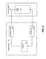
- FIG. 2is a block diagram of an exemplary embodiment of charging system 120 of FIG. 1 .
- Charging system 120in an exemplary embodiment, includes controller 205 , which may be any hardware and/or software suitably configured to switch ON and OFF a charging source. As such, controller 205 may be any controller known in the art capable of switching ON and OFF charging sources when appropriate to do such.
- controller 205is connected to charging source(s) 210 .
- Charging source 210may be any hardware and/or software suitably configured to provide charging current to at least one battery cell when switched ON (i.e., operating in a charging state), and not provide charging current to a battery cell when switched OFF (i.e., operating in a non-charging state).
- charging source 210may be any charging source known in the art capable of charging one or more battery cells.
- charging system 120includes a series string of battery cells 240 (series string 240 ).
- Series string 240in an exemplary embodiment, includes one or more individual battery cells (not shown), wherein each battery cell voltage is dependent on the cell chemistry.
- series string 240may be configured to form a secondary battery of any desired voltage.
- Charging system 120in another exemplary embodiment, includes at least one cell monitor 250 connected to a respective battery cell and controller 205 .
- Cell monitor 250may be any hardware and/or software suitably configured to monitor the terminal voltage of one or more battery cells. As such, cell monitor 250 may be any cell monitor known in the art capable of detecting the terminal voltage of an individual or plurality of battery cells. In one aspect of the invention, cell monitor 250 may be configured to detect the terminal voltage of a battery cell (with a pre-determined amount of error tolerance). In another aspect of the invention, cell monitor 250 may be configured to determine if a battery cell, with which cell monitor 250 is associated, contains a terminal voltage above or below a pre-determined threshold level.
- cell monitor 250in an exemplary embodiment, is configured to communicate the terminal voltage of a battery cell and/or whether the battery cell contains above or below the threshold amount of charge to controller 205 .
- the term “above” with reference to a terminal voltage and/or a threshold amount of voltagemeans substantially the same as or greater than the amount.
- charging system 120may be formed on a printed circuit board (PCB) (not shown) or on any other platform known in the art suitable for forming and/or operating charging system 120 .
- PCBprinted circuit board
- FIG. 3is a block diagram of one exemplary embodiment of a topology 300 of charging system 120 .
- topology 300includes a power source 301 connected to a charging source 312 , a charging source 314 , a charging source 316 , and a charging source 318 .
- power source 301is configured similar to power source 110 discussed above, and charging sources 312 , 314 , 316 , and 318 are each configured similar to charging source 210 discussed above.
- charging source 312is connected to battery cell 342 via positive path 322 and negative path 332 .
- charging source 312is coupled in parallel to battery cell 342 , wherein charging source 312 is coupled to the positive terminal (V+) and negative terminal (V ⁇ ) of battery cell 342 via positive path 322 and negative path 332 , respectively.
- charging source 314is connected to battery cell 344 via positive path 324 and negative path 334 .
- charging source 314is coupled in parallel to battery cell 344 , wherein charging source 314 is coupled to V+ and V ⁇ of battery cell 342 via positive path 324 and negative path 334 , respectively.
- Charging source 316in an exemplary embodiment, is connected to battery cell 346 via positive path 326 and negative path 336 .
- charging source 316is coupled in parallel to battery cell 346 , wherein charging source 316 is coupled to V+ and V ⁇ of battery cell 346 via positive path 326 and negative path 336 , respectively.
- charging source 318is connected to battery cell 348 via positive path 328 and negative path 338 .
- charging source 318is coupled in parallel to battery cell 348 , wherein charging source 318 is coupled to V+ and V ⁇ of battery cell 348 via positive path 328 and negative path 338 , respectively.
- Battery cells 342 , 344 , 346 , and 348are lithium-ion battery cells.
- battery cells 342 , 344 , 346 , and 348may be, but are not limited to, lead-acid battery cells, nickel-cadmium battery cells, nickel-metal hydride battery cells, nickel hydrogen battery cells, silver-zinc battery cells, or any other battery cells capable of storing a charge and subsequently being recharged after discharge.
- the inventioncontemplates that battery cells 342 , 344 , 346 , and 348 may each be any size battery cell known in the art.
- Positive paths 322 , 324 , 326 , and 328may be any hardware and/or device suitably configured to conduct charging current. As such, positive paths 322 , 324 , 326 , and 328 may be formed of any material known in the art capable of conducting charging current supplied from a charging source to a battery cell to charge the battery cell. Negative paths 332 , 334 , 336 , and 338 may also be any hardware and/or device suitably configured to conduct charging current. As such negative paths 332 , 334 , 336 , and 338 may be formed of any material known in the art capable of conducting and/or returning charging current from a battery cell to a charging source.
- Charging sources 312 , 314 , 316 , and 318are each connected to a controller 305 , wherein controller 305 is configured similar to controller 205 discussed above. Controller 305 , in one exemplary embodiment, is configured to transmit charging source control signals 307 to charging sources 3312 , 314 , 316 , and 318 to control the ON/OFF operation of charging sources 312 , 314 , 316 , and 318 .
- Topology 300also includes a cell monitor 352 , a cell monitor 354 , a cell monitor 356 , and a cell monitor 358 , wherein cell monitors 352 , 354 , 356 , and 358 are each configured similar to cell monitor 250 discussed above.
- cell monitors 352 , 354 , 356 , and 358are connected to battery cells 342 , 344 , 346 , and 348 , respectively, and are each connected to controller 305 .
- cell monitors 352 , 354 , 356 , and 358are each suitably connected to battery cells 342 , 344 , 346 , and 348 such that cell monitors 352 , 354 , 356 , and 358 are each capable of determining the amount of charge contained within battery cells 342 , 344 , 346 , and 348 , respectively.
- cell monitors 352 , 354 , 356 , and 358are suitably connected to controller 305 such that cell monitors 352 , 354 , 356 , and 358 are capable of communicating the amount of charge (or whether their respective battery cell includes an amount of charge above or below a threshold amount) contained within battery cells 342 , 344 , 346 , and 348 , respectively, to controller 305 .
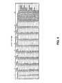
- FIG. 4is a control truth table and operational chart for topology 300 , as illustrated in FIG. 3 .
- column 1reflects the 16 different possible permutations of the exemplary embodiment of FIG. 3 .
- Columns 2, 3, 4, and 5indicate the state of charge (i.e., fully charged (high) or not fully charged (low)) of battery cells 342 , 344 , 346 , and 348 , respectively.
- Columns 6, 7, 8, and 9indicate the state of operation (i.e., ON or OFF) of charging sources 312 , 314 , 316 , and 318 , respectively, and column 10 indicates the state of operation of topology 300 (i.e., charging system 120 ).
- battery cells 342 , 346 , and 348are not fully charged and need to be charged, whereas battery cell 344 is fully charged (i.e., the cell voltage is above a threshold amount) and should not be further charged (i.e., over-charged).
- charging sources 312 , 316 , and 318will be switched ON by controller 305 (whereas charging source 314 will remain switched OFF) to provide charging current to battery cells 342 , 346 , and 348 , respectively.
- charging currentis supplied to battery cell 342 from charging source 312 , wherein the charging current is supplied through positive path 322 to charge battery cell 342 , then returns to charging source 312 via negative path 332 so as not to supply charging current to battery cells 344 , 346 , and 348 .
- charging current in supplied to battery cell 346 from charging source 316wherein the charging current is supplied through positive path 326 to charge battery cell 346 , then returns to charging source 316 via negative path 336 so as not to supply charging current to battery cells 342 , 344 , and 348 .
- charging currentis supplied to battery cell 348 from charging source 318 , wherein the charging current is supplied through positive path 328 to charge battery cell 348 , then returns to charging source 318 via negative path 338 so as not to supply charging current to battery cells 342 , 344 , and 346 .
- Permutation 10is another example of how topology 300 provides charging current to battery cells needing to be charged, but yet does not provide charging current to battery cells fully charged or have a cell voltage above a threshold amount.
- battery cells 344 and 346need to be charged, whereas battery cells 342 and 348 are fully charged (i.e., a cell voltage above a threshold amount) and should not be further charged (i.e., over-charged).
- charging sources 314 and 316are switched ON by controller 305 (whereas charging sources 312 and 318 will remain switched OFF) to provide charging current to battery cells 344 and 346 , respectively.
- charging currentis supplied to battery cell 344 from charging source 314 , wherein the charging current is supplied through positive path 324 to charge battery cell 344 , then returns to charging source 314 via negative path 334 so as not to supply charging current to battery cells 342 , 346 , and 348 .
- charging currentis supplied to battery cell 346 from charging source 316 , wherein the charging current is supplied through positive path 326 to charge battery cell 346 , then returns to charging source 316 via negative path 336 so as not to supply charging current to battery cells 342 , 344 , and 348 .
- Permutation 15illustrates the example of when only one battery cell (i.e., battery cell 318 ) requires charging.
- controller 305switches ON charging source 318 such that charging current will flow from charging source 318 via positive path 328 to battery cell 348 , and return to charging source 318 via negative path 338 .
- battery cells 312 , 314 , and 316do not receive charging current since they are fully charged and/or charged above the minimum threshold voltage amount.
- charging system 120may include any number of battery cells in series string 240 , and corresponding charging sources and cell monitors without departing from the spirit and scope of the invention.
- negative path 338may be omitted since charging current leaving battery cell 348 will not charge any other battery cell, but will instead, flow to ground.
- FIG. 5is a flow diagram of an exemplary embodiment of a method 500 for charging a secondary battery utilizing cell equalization.
- method 500initiates by coupling N battery cells (e.g., battery cells 342 , 244 , 246 , and 348 ) in series to form a series string (e.g., series string 240 ) on a platform (step 510 ).
- the step of coupling N battery cellsincludes coupling a different battery cell to a load end (step 520 ), and coupling a battery cell to a ground end (step 530 ).
- method 500also includes coupling a plurality of charging sources (e.g., charging sources 312 , 214 , 316 , and 318 ) in parallel to the N battery cells (step 540 ).
- a plurality of charging sourcese.g., charging sources 312 , 214 , 316 , and 318
- coupling the plurality of charging sources in parallelincludes coupling each charging source to a respective battery cell via a positive path (e.g., positive path 322 ) and a negative path (e.g., negative path 332 ).
- Method 500includes configuring each charging source to selectively provide charging current to a single battery cell in series string 240 (step 550 ).
- configuring each charging sourcemay include configuring each charging source to provide charging current to each battery cell containing an amount of voltage below a threshold amount, and not provide charging current to each cell containing an amount of voltage above the threshold amount.
- configuring each charging sourcemay include configuring each charging source to operate in a charging state to provide charging current to a respective battery cell, and configuring each charging source to operate in a non-charging state to not provide charging current to the battery cell.
- method 500includes coupling each charging source to a power source (e.g., power source 110 ) to provide power to each charging source (step 560 ).
- method 500includes coupling a cell monitor to each battery cell to monitor the voltage level of each of battery cell (step 570 ).
- Method 500in still another embodiment, includes configuring the cell monitors to determine which battery cell(s) contain an amount of voltage above and/or below the threshold amount (step 580 ).
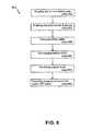
- FIG. 6is a flow diagram of another exemplary embodiment of a method 600 for equalizing the voltage of a secondary battery being charged including coupling two or more battery cells (e.g., battery cells 342 , 344 , 346 . and 348 ) in series to form a series string (e.g., series string 240 ) (step 610 ).
- method 600includes coupling a charging source (e.g., charging source 312 ) in parallel across each battery cell (step 620 ).
- Method 600in another exemplary embodiment, includes charging any battery cell(s) containing an amount of voltage below a threshold level (step 630 ), and not charging any battery cell(s) containing an amount of voltage above the threshold level (step 640 ).
- charging a battery cellmay include providing charging current to a particular battery cell via a charging source coupled in parallel to the battery cell.
- charging a battery cellmay include switching ON a charging source to charge a particular battery cell needing to be charged, and switching OFF the charging source to stop charging the battery cell when it contains a voltage level above the threshold amount.
- method 600also includes monitoring the voltage level of battery cell in the series string (step 650 ). In another embodiment, method 600 includes operating each charging source independently in an ON state or in an OFF state based on the voltage level of a battery cell connected to the charging source (step 660 ).
- the terms “comprises,” “comprising,” or any other variation thereof,are intended to cover a non-exclusive inclusion, such that a process, method, article, or apparatus that comprises a list of elements does not include only those elements but may include other elements not expressly listed or inherent to such process, method, article, or apparatus. Further, no element described herein is required for the practice of the invention unless expressly described as “essential” or “critical.”
Landscapes
- Engineering & Computer Science (AREA)
- Power Engineering (AREA)
- Secondary Cells (AREA)
- Charge And Discharge Circuits For Batteries Or The Like (AREA)
Abstract
Description
Claims (14)
Priority Applications (1)
| Application Number | Priority Date | Filing Date | Title |
|---|---|---|---|
| US11/163,668US7928691B2 (en) | 2004-11-10 | 2005-10-26 | Method and system for cell equalization with isolated charging sources |
Applications Claiming Priority (2)
| Application Number | Priority Date | Filing Date | Title |
|---|---|---|---|
| US52281504P | 2004-11-10 | 2004-11-10 | |
| US11/163,668US7928691B2 (en) | 2004-11-10 | 2005-10-26 | Method and system for cell equalization with isolated charging sources |
Publications (2)
| Publication Number | Publication Date |
|---|---|
| US20060097696A1 US20060097696A1 (en) | 2006-05-11 |
| US7928691B2true US7928691B2 (en) | 2011-04-19 |
Family
ID=36315664
Family Applications (1)
| Application Number | Title | Priority Date | Filing Date |
|---|---|---|---|
| US11/163,668ActiveUS7928691B2 (en) | 2004-11-10 | 2005-10-26 | Method and system for cell equalization with isolated charging sources |
Country Status (1)
| Country | Link |
|---|---|
| US (1) | US7928691B2 (en) |
Cited By (14)
| Publication number | Priority date | Publication date | Assignee | Title |
|---|---|---|---|---|
| US20090230921A1 (en)* | 2006-08-01 | 2009-09-17 | Aeneas Energy Technology Co., Ltd. | Charging circuit for balance charging serially connected batteries |
| US20100244781A1 (en)* | 2009-01-14 | 2010-09-30 | Quentin Wayne Kramer | Cell management system |
| US20120019209A1 (en)* | 2009-02-06 | 2012-01-26 | Holger Fink | More readily available traction battery |
| US20120290234A1 (en)* | 2011-05-13 | 2012-11-15 | Gm Global Technology Operations, Llc. | Systems and methods for determining cell capacity values in a multi-cell battery |
| US20120306451A1 (en)* | 2010-02-26 | 2012-12-06 | Ricoh Company, Ltd. | Secondary cell protection circuit and battery |
| US20140062388A1 (en)* | 2012-09-06 | 2014-03-06 | Samsung Sdl Co., Ltd. | Cell balancing circuit and cell balancing method using the same |
| US8768419B2 (en)* | 2012-01-26 | 2014-07-01 | Verizon Patent And Licensing Inc. | Mobile battery partitioning system and method |
| US20160094906A1 (en)* | 2014-09-29 | 2016-03-31 | Qualcomm Incorporated | Electronics interface for device headset jack |
| US20170288422A1 (en)* | 2011-04-22 | 2017-10-05 | Sk Innovation Co., Ltd. | Charge equalization apparatus for a battery string |
| US9786432B2 (en) | 2011-08-19 | 2017-10-10 | Leviticus Cardio Ltd. | Coplanar energy transfer |
| US9793579B2 (en) | 2013-11-08 | 2017-10-17 | Leviticus Cardio Ltd. | Batteries for use in implantable medical devices |
| US9912164B2 (en)* | 2014-12-24 | 2018-03-06 | Intel Corporation | Multisource power delivery system |
| US10543303B2 (en) | 2013-11-08 | 2020-01-28 | Leviticus Cardio Ltd. | Batteries for use in implantable medical devices |
| US11269392B2 (en)* | 2018-10-01 | 2022-03-08 | Ge Aviation Systems Limited | System and method for maintaining power source |
Families Citing this family (17)
| Publication number | Priority date | Publication date | Assignee | Title |
|---|---|---|---|---|
| US20060097697A1 (en)* | 2004-11-10 | 2006-05-11 | Eaglepicher Technologies, Llc | Method and system for cell equalization with switched charging sources |
| US7928691B2 (en) | 2004-11-10 | 2011-04-19 | EaglePicher Technologies | Method and system for cell equalization with isolated charging sources |
| US20060097700A1 (en)* | 2004-11-10 | 2006-05-11 | Eaglepicher Technologies, Llc | Method and system for cell equalization with charging sources and shunt regulators |
| DE102005034588A1 (en)* | 2005-07-25 | 2007-02-01 | Temic Automotive Electric Motors Gmbh | energy storage |
| US7496460B2 (en)* | 2006-09-06 | 2009-02-24 | Eastway Fair Company Limited | Energy source monitoring and control system for power tools |
| CA2717789C (en) | 2007-12-11 | 2018-07-31 | Antonio Trigiani | Battery management system |
| US20110234165A1 (en)* | 2010-03-29 | 2011-09-29 | Dennis Palatov | Modular Charging System for Multi-Cell Series-Connected Battery Packs |
| US10879729B2 (en)* | 2010-05-26 | 2020-12-29 | Zincfive, Llc | Backup battery systems for traffic cabinets |
| JP5801176B2 (en)* | 2011-12-19 | 2015-10-28 | 株式会社東芝 | Power storage device and maintenance method thereof |
| DE102012207674A1 (en)* | 2012-05-09 | 2013-11-14 | Robert Bosch Gmbh | Method and device for adjusting the states of charge of a battery |
| CN103236726A (en)* | 2013-04-23 | 2013-08-07 | 深圳市乐迪电子有限公司 | Independent charge control system of battery and quick charge and discharge detection control system |
| CN104578308A (en)* | 2015-01-25 | 2015-04-29 | 浙江大学 | Parallel connection charging module for AUV wireless charging |
| JP7086651B2 (en)* | 2018-03-14 | 2022-06-20 | 株式会社東芝 | Storage battery system and control method of storage battery system |
| CN108767940B (en)* | 2018-08-07 | 2024-05-14 | 西安爱科赛博电气股份有限公司 | Active equalization device and active equalization method for parallel charging of series rechargeable batteries |
| JP7470638B2 (en)* | 2018-08-29 | 2024-04-18 | ヌヴォトンテクノロジージャパン株式会社 | Management system and cell monitoring circuit |
| US11117483B2 (en)* | 2019-10-02 | 2021-09-14 | Ford Global Technologies, Llc | Traction battery charging method and charging system |
| CN212649154U (en)* | 2020-08-07 | 2021-03-02 | 上海峰飞航空科技有限公司 | Balanced charging device and charging system |
Citations (53)
| Publication number | Priority date | Publication date | Assignee | Title |
|---|---|---|---|---|
| US4238721A (en)* | 1979-02-06 | 1980-12-09 | The United States Of America As Represented By The United States Department Of Energy | System and method for charging electrochemical cells in series |
| US4467266A (en) | 1982-03-29 | 1984-08-21 | Mcgraw-Edison Company | Battery overcharge protection system |
| US5498950A (en)* | 1994-04-29 | 1996-03-12 | Delco Electronics Corp. | Battery monitoring, charging and balancing apparatus |
| US5504415A (en) | 1993-12-03 | 1996-04-02 | Electronic Power Technology, Inc. | Method and apparatus for automatic equalization of series-connected batteries |
| JPH08237861A (en) | 1995-02-27 | 1996-09-13 | Okamura Kenkyusho:Kk | Parallel charge control device, power storage device, and charge control method |
| US5592067A (en) | 1994-01-06 | 1997-01-07 | General Motors Corporation | Distributed multi-module battery equalization |
| US5631534A (en) | 1995-08-21 | 1997-05-20 | Delco Electronics Corp. | Bidirectional current pump for battery charge balancing |
| US5656915A (en) | 1995-08-28 | 1997-08-12 | Eaves; Stephen S. | Multicell battery pack bilateral power distribution unit with individual cell monitoring and control |
| US5659208A (en)* | 1995-07-14 | 1997-08-19 | International Business Machines Corporation | Power supply with multiple isolated regulators and isolation mode |
| US5710504A (en) | 1996-05-20 | 1998-01-20 | The Board Of Trustees Of The University Of Illinois | Switched capacitor system for automatic battery equalization |
| US5811959A (en)* | 1996-12-27 | 1998-09-22 | Kejha; Joseph B. | Smart circuit board for multicell battery protection |
| US5821733A (en) | 1994-02-22 | 1998-10-13 | Packard Bell Nec | Multiple cell and serially connected rechargeable batteries and charging system |
| US5850136A (en)* | 1996-12-26 | 1998-12-15 | Integran, Inc. | Battery charger |
| US5867007A (en) | 1996-09-03 | 1999-02-02 | Samsung Electronics Co., Ltd. | Selection circuit for dual batteries in a battery powered electronic device |
| US5920179A (en) | 1997-05-05 | 1999-07-06 | Aer Energy Resources, Inc. | System and method for balancing charge cycles for batteries or multiple-cell battery packs |
| US5945804A (en) | 1996-08-30 | 1999-08-31 | Telefonaktiebolaget Lm Ericsson | Method and device for controlling the voltage across individual cells in a battery |
| US5952815A (en) | 1997-07-25 | 1999-09-14 | Minnesota Mining & Manufacturing Co. | Equalizer system and method for series connected energy storing devices |
| US5965996A (en)* | 1997-12-11 | 1999-10-12 | Vectrix Corporation | Electrical scooter having an equalization circuit for charging multiple batteries |
| US6064178A (en) | 1998-05-07 | 2000-05-16 | Ford Motor Company | Battery charge balancing system having parallel switched energy storage elements |
| US6094031A (en)* | 1998-06-08 | 2000-07-25 | Honda Giken Kogyo Kabushiki Kaisha | Battery condition-detecting apparatus and battery condition-detecting unit using an optical signal |
| US6097174A (en) | 1998-09-18 | 2000-08-01 | Yang; Tai-Her | Individually adjustable type automatic charging circuit for multiple batteries |
| US6140800A (en) | 1999-05-27 | 2000-10-31 | Peterson; William Anders | Autonomous battery equalization circuit |
| US6150795A (en) | 1999-11-05 | 2000-11-21 | Power Designers, Llc | Modular battery charge equalizers and method of control |
| US6157167A (en) | 1998-04-29 | 2000-12-05 | The Johns Hopkins University | Topology for individual battery cell charge control in a rechargeable battery cell array |
| US6181106B1 (en) | 1996-07-18 | 2001-01-30 | Curtis Instruments, Inc. | Sequential high-rate charging of battery cells |
| US6222344B1 (en) | 1999-12-06 | 2001-04-24 | Bae Systems Controls, Inc. | Magnetically coupled autonomous battery equalization circuit |
| US6268710B1 (en)* | 1999-07-09 | 2001-07-31 | Fujitsu Limited | Battery monitor apparatus |
| US6316917B1 (en) | 1999-03-09 | 2001-11-13 | Asahi Glass Company, Limited | Apparatus having plural electric double layer capacitors and method for adjusting voltages of the capacitors |
| US6326768B2 (en) | 1999-12-27 | 2001-12-04 | Sony Corporation | Method, apparatus and battery pack for charging and discharging secondary batteries |
| US6377024B1 (en)* | 2001-03-23 | 2002-04-23 | The Boeing Company | Method and system for charge equalization of lithium-ion batteries |
| US20020047685A1 (en) | 2000-10-23 | 2002-04-25 | Alcatel | Method, arrangement and interface system to enable electrical batteries of different kinds to be charged by means of the same charger device |
| US6388424B1 (en) | 2000-12-14 | 2002-05-14 | Mitsubishi Denki Kabushiki Kaisha | Cell shunt circuit for battery cells |
| US20020084770A1 (en) | 2000-12-28 | 2002-07-04 | C.E. Niehoff & Co. | Multiple battery charge equalizer |
| US20020195994A1 (en) | 2001-06-07 | 2002-12-26 | Alcatel | Method of balancing an electrical battery subjected to discontinuous charging, and a battery management system for implementing the method |
| US20030042870A1 (en) | 2001-09-03 | 2003-03-06 | Yau Kwok Wong | Intelligent serial battery charger and charging block |
| US6580251B2 (en)* | 2001-04-20 | 2003-06-17 | Seiko Epson Corporation | Power charging device using multiple energy sources |
| US20030113600A1 (en) | 2001-12-14 | 2003-06-19 | Ballard Power Systems Inc. | Fuel cell system shunt regulator method and apparatus |
| US6586917B1 (en) | 2001-10-19 | 2003-07-01 | National Semiconductor Corporation | Battery charger shunt regulator with dual feedback control |
| US20030139888A1 (en) | 2001-11-27 | 2003-07-24 | Burns Charles E. | Battery management system and method |
| US6608470B1 (en) | 1998-01-31 | 2003-08-19 | Motorola, Inc. | Overcharge protection device and methods for lithium based rechargeable batteries |
| US20030160593A1 (en) | 2001-09-03 | 2003-08-28 | Gpe International Limited, New Terrritories | Intelligent serial battery charger and charging block |
| US20030218446A1 (en) | 2000-11-30 | 2003-11-27 | Rolf Beerwerth | Circuit for charging rechargeable batteries |
| US20040012371A1 (en)* | 2002-07-22 | 2004-01-22 | Ott William E. | Battery charger |
| US6703722B2 (en)* | 2001-12-14 | 2004-03-09 | Avista Laboratories, Inc. | Reconfigurable plural DC power source power system responsive to changes in the load or the plural DC power sources |
| US20040135544A1 (en)* | 2002-11-25 | 2004-07-15 | Tiax, Llc | System and method for determining and balancing state of charge among series connected electrical energy storage units |
| US20040145346A1 (en)* | 2003-01-24 | 2004-07-29 | Hall John C. | Charge control circuit and method for charging multiple battery cells |
| US20040164706A1 (en)* | 2001-03-30 | 2004-08-26 | Osborne Jeffrey Roger | Battery management unit, system and method |
| US6841971B1 (en) | 2002-05-29 | 2005-01-11 | Alpha Technologies, Inc. | Charge balancing systems and methods |
| US20060097696A1 (en) | 2004-11-10 | 2006-05-11 | Eaglepicher Technologies, Llc | Method and system for cell equalization with isolated charging sources |
| US20060097700A1 (en) | 2004-11-10 | 2006-05-11 | Eaglepicher Technologies, Llc | Method and system for cell equalization with charging sources and shunt regulators |
| US20060097697A1 (en) | 2004-11-10 | 2006-05-11 | Eaglepicher Technologies, Llc | Method and system for cell equalization with switched charging sources |
| US7061207B2 (en)* | 2002-08-09 | 2006-06-13 | H2Eye (International ) Limited | Cell equalizing circuit |
| US20070063670A1 (en) | 2003-09-29 | 2007-03-22 | Christophe Taurand | System for quilibrating an energy storage device |
- 2005
- 2005-10-26USUS11/163,668patent/US7928691B2/enactiveActive
Patent Citations (59)
| Publication number | Priority date | Publication date | Assignee | Title |
|---|---|---|---|---|
| US4238721A (en)* | 1979-02-06 | 1980-12-09 | The United States Of America As Represented By The United States Department Of Energy | System and method for charging electrochemical cells in series |
| US4467266A (en) | 1982-03-29 | 1984-08-21 | Mcgraw-Edison Company | Battery overcharge protection system |
| US5504415A (en) | 1993-12-03 | 1996-04-02 | Electronic Power Technology, Inc. | Method and apparatus for automatic equalization of series-connected batteries |
| US5592067A (en) | 1994-01-06 | 1997-01-07 | General Motors Corporation | Distributed multi-module battery equalization |
| US5821733A (en) | 1994-02-22 | 1998-10-13 | Packard Bell Nec | Multiple cell and serially connected rechargeable batteries and charging system |
| US5498950A (en)* | 1994-04-29 | 1996-03-12 | Delco Electronics Corp. | Battery monitoring, charging and balancing apparatus |
| JPH08237861A (en) | 1995-02-27 | 1996-09-13 | Okamura Kenkyusho:Kk | Parallel charge control device, power storage device, and charge control method |
| US5659208A (en)* | 1995-07-14 | 1997-08-19 | International Business Machines Corporation | Power supply with multiple isolated regulators and isolation mode |
| US5631534A (en) | 1995-08-21 | 1997-05-20 | Delco Electronics Corp. | Bidirectional current pump for battery charge balancing |
| US5656915A (en) | 1995-08-28 | 1997-08-12 | Eaves; Stephen S. | Multicell battery pack bilateral power distribution unit with individual cell monitoring and control |
| US5710504A (en) | 1996-05-20 | 1998-01-20 | The Board Of Trustees Of The University Of Illinois | Switched capacitor system for automatic battery equalization |
| US6181106B1 (en) | 1996-07-18 | 2001-01-30 | Curtis Instruments, Inc. | Sequential high-rate charging of battery cells |
| US5945804A (en) | 1996-08-30 | 1999-08-31 | Telefonaktiebolaget Lm Ericsson | Method and device for controlling the voltage across individual cells in a battery |
| US5867007A (en) | 1996-09-03 | 1999-02-02 | Samsung Electronics Co., Ltd. | Selection circuit for dual batteries in a battery powered electronic device |
| US5850136A (en)* | 1996-12-26 | 1998-12-15 | Integran, Inc. | Battery charger |
| US5811959A (en)* | 1996-12-27 | 1998-09-22 | Kejha; Joseph B. | Smart circuit board for multicell battery protection |
| US5920179A (en) | 1997-05-05 | 1999-07-06 | Aer Energy Resources, Inc. | System and method for balancing charge cycles for batteries or multiple-cell battery packs |
| US5952815A (en) | 1997-07-25 | 1999-09-14 | Minnesota Mining & Manufacturing Co. | Equalizer system and method for series connected energy storing devices |
| US5965996A (en)* | 1997-12-11 | 1999-10-12 | Vectrix Corporation | Electrical scooter having an equalization circuit for charging multiple batteries |
| US6608470B1 (en) | 1998-01-31 | 2003-08-19 | Motorola, Inc. | Overcharge protection device and methods for lithium based rechargeable batteries |
| US6157167A (en) | 1998-04-29 | 2000-12-05 | The Johns Hopkins University | Topology for individual battery cell charge control in a rechargeable battery cell array |
| US6064178A (en) | 1998-05-07 | 2000-05-16 | Ford Motor Company | Battery charge balancing system having parallel switched energy storage elements |
| US6094031A (en)* | 1998-06-08 | 2000-07-25 | Honda Giken Kogyo Kabushiki Kaisha | Battery condition-detecting apparatus and battery condition-detecting unit using an optical signal |
| US6097174A (en) | 1998-09-18 | 2000-08-01 | Yang; Tai-Her | Individually adjustable type automatic charging circuit for multiple batteries |
| US6316917B1 (en) | 1999-03-09 | 2001-11-13 | Asahi Glass Company, Limited | Apparatus having plural electric double layer capacitors and method for adjusting voltages of the capacitors |
| US6140800A (en) | 1999-05-27 | 2000-10-31 | Peterson; William Anders | Autonomous battery equalization circuit |
| US6268710B1 (en)* | 1999-07-09 | 2001-07-31 | Fujitsu Limited | Battery monitor apparatus |
| US6150795A (en) | 1999-11-05 | 2000-11-21 | Power Designers, Llc | Modular battery charge equalizers and method of control |
| US6222344B1 (en) | 1999-12-06 | 2001-04-24 | Bae Systems Controls, Inc. | Magnetically coupled autonomous battery equalization circuit |
| US6326768B2 (en) | 1999-12-27 | 2001-12-04 | Sony Corporation | Method, apparatus and battery pack for charging and discharging secondary batteries |
| US6441583B1 (en) | 2000-10-23 | 2002-08-27 | Alcatel | Method, arrangement and interface system to enable electrical batteries of different kinds to be charged by means of the same charger device |
| US20020047685A1 (en) | 2000-10-23 | 2002-04-25 | Alcatel | Method, arrangement and interface system to enable electrical batteries of different kinds to be charged by means of the same charger device |
| US20030218446A1 (en) | 2000-11-30 | 2003-11-27 | Rolf Beerwerth | Circuit for charging rechargeable batteries |
| US6388424B1 (en) | 2000-12-14 | 2002-05-14 | Mitsubishi Denki Kabushiki Kaisha | Cell shunt circuit for battery cells |
| US20020084770A1 (en) | 2000-12-28 | 2002-07-04 | C.E. Niehoff & Co. | Multiple battery charge equalizer |
| US6452363B1 (en) | 2000-12-28 | 2002-09-17 | C. E. Niehoff & Co. | Multiple battery charge equalizer |
| US6377024B1 (en)* | 2001-03-23 | 2002-04-23 | The Boeing Company | Method and system for charge equalization of lithium-ion batteries |
| US20040164706A1 (en)* | 2001-03-30 | 2004-08-26 | Osborne Jeffrey Roger | Battery management unit, system and method |
| US6580251B2 (en)* | 2001-04-20 | 2003-06-17 | Seiko Epson Corporation | Power charging device using multiple energy sources |
| US20020195994A1 (en) | 2001-06-07 | 2002-12-26 | Alcatel | Method of balancing an electrical battery subjected to discontinuous charging, and a battery management system for implementing the method |
| US6580249B2 (en) | 2001-09-03 | 2003-06-17 | Gpe International Limited | Intelligent serial battery charger and charging block |
| US20030042870A1 (en) | 2001-09-03 | 2003-03-06 | Yau Kwok Wong | Intelligent serial battery charger and charging block |
| US20030160593A1 (en) | 2001-09-03 | 2003-08-28 | Gpe International Limited, New Terrritories | Intelligent serial battery charger and charging block |
| US6822423B2 (en) | 2001-09-03 | 2004-11-23 | Gpe International Limited | Intelligent serial battery charger and charging block |
| US6586917B1 (en) | 2001-10-19 | 2003-07-01 | National Semiconductor Corporation | Battery charger shunt regulator with dual feedback control |
| US6983212B2 (en)* | 2001-11-27 | 2006-01-03 | American Power Conversion Corporation | Battery management system and method |
| US20030139888A1 (en) | 2001-11-27 | 2003-07-24 | Burns Charles E. | Battery management system and method |
| US20030113600A1 (en) | 2001-12-14 | 2003-06-19 | Ballard Power Systems Inc. | Fuel cell system shunt regulator method and apparatus |
| US6703722B2 (en)* | 2001-12-14 | 2004-03-09 | Avista Laboratories, Inc. | Reconfigurable plural DC power source power system responsive to changes in the load or the plural DC power sources |
| US6841971B1 (en) | 2002-05-29 | 2005-01-11 | Alpha Technologies, Inc. | Charge balancing systems and methods |
| US20040012371A1 (en)* | 2002-07-22 | 2004-01-22 | Ott William E. | Battery charger |
| US6791297B2 (en) | 2002-07-22 | 2004-09-14 | Honeywell International Inc. | Battery charger |
| US7061207B2 (en)* | 2002-08-09 | 2006-06-13 | H2Eye (International ) Limited | Cell equalizing circuit |
| US20040135544A1 (en)* | 2002-11-25 | 2004-07-15 | Tiax, Llc | System and method for determining and balancing state of charge among series connected electrical energy storage units |
| US20040145346A1 (en)* | 2003-01-24 | 2004-07-29 | Hall John C. | Charge control circuit and method for charging multiple battery cells |
| US20070063670A1 (en) | 2003-09-29 | 2007-03-22 | Christophe Taurand | System for quilibrating an energy storage device |
| US20060097696A1 (en) | 2004-11-10 | 2006-05-11 | Eaglepicher Technologies, Llc | Method and system for cell equalization with isolated charging sources |
| US20060097700A1 (en) | 2004-11-10 | 2006-05-11 | Eaglepicher Technologies, Llc | Method and system for cell equalization with charging sources and shunt regulators |
| US20060097697A1 (en) | 2004-11-10 | 2006-05-11 | Eaglepicher Technologies, Llc | Method and system for cell equalization with switched charging sources |
Non-Patent Citations (6)
| Title |
|---|
| Final Office Action for U.S. Appl. No. 11/163,667 dated Feb. 6, 2008. |
| Final Office Action for U.S. Appl. No. 11/163,669 dated Feb. 6, 2008. |
| Non-final Office Action for U.S. Appl. No. 11/163,667 dated Jul. 25, 2008. |
| Non-final Office Action for U.S. Appl. No. 11/163,667 dated Sep. 11, 2007. |
| Non-final Office Action for U.S. Appl. No. 11/163,669 dated Aug. 16, 2007. |
| Non-final Office Action for U.S. Appl. No. 11/163,669 dated Jul. 28, 2008. |
Cited By (23)
| Publication number | Priority date | Publication date | Assignee | Title |
|---|---|---|---|---|
| US8288999B2 (en)* | 2006-08-01 | 2012-10-16 | Aeneas Energy Technology Co., Ltd. | Charging circuit for balance charging serially connected batteries |
| US20090230921A1 (en)* | 2006-08-01 | 2009-09-17 | Aeneas Energy Technology Co., Ltd. | Charging circuit for balance charging serially connected batteries |
| US20100244781A1 (en)* | 2009-01-14 | 2010-09-30 | Quentin Wayne Kramer | Cell management system |
| US8288992B2 (en)* | 2009-01-14 | 2012-10-16 | Indy Power Systems, Llc | Cell management system |
| US9041341B2 (en)* | 2009-02-06 | 2015-05-26 | Robert Bosch Gmbh | More readily available traction battery |
| US20120019209A1 (en)* | 2009-02-06 | 2012-01-26 | Holger Fink | More readily available traction battery |
| US20120306451A1 (en)* | 2010-02-26 | 2012-12-06 | Ricoh Company, Ltd. | Secondary cell protection circuit and battery |
| US9106081B2 (en)* | 2010-02-26 | 2015-08-11 | Ricoh Electronic Devices Co., Ltd. | Secondary cell protection circuit and battery |
| US20170288422A1 (en)* | 2011-04-22 | 2017-10-05 | Sk Innovation Co., Ltd. | Charge equalization apparatus for a battery string |
| US10680447B2 (en)* | 2011-04-22 | 2020-06-09 | Sk Innovation Co., Ltd. | Charge equalization apparatus for a battery string |
| US9037426B2 (en)* | 2011-05-13 | 2015-05-19 | GM Global Technology Operations LLC | Systems and methods for determining cell capacity values in a multi-cell battery |
| US20120290234A1 (en)* | 2011-05-13 | 2012-11-15 | Gm Global Technology Operations, Llc. | Systems and methods for determining cell capacity values in a multi-cell battery |
| US9786432B2 (en) | 2011-08-19 | 2017-10-10 | Leviticus Cardio Ltd. | Coplanar energy transfer |
| US8768419B2 (en)* | 2012-01-26 | 2014-07-01 | Verizon Patent And Licensing Inc. | Mobile battery partitioning system and method |
| US20140062388A1 (en)* | 2012-09-06 | 2014-03-06 | Samsung Sdl Co., Ltd. | Cell balancing circuit and cell balancing method using the same |
| US9318910B2 (en)* | 2012-09-06 | 2016-04-19 | Samsung Sdi Co., Ltd. | Cell balancing circuit and cell balancing method using the same |
| US10543303B2 (en) | 2013-11-08 | 2020-01-28 | Leviticus Cardio Ltd. | Batteries for use in implantable medical devices |
| US9793579B2 (en) | 2013-11-08 | 2017-10-17 | Leviticus Cardio Ltd. | Batteries for use in implantable medical devices |
| US10561775B2 (en) | 2013-11-08 | 2020-02-18 | Leviticus Cardio Ltd. | Alerting a patient |
| US20160094906A1 (en)* | 2014-09-29 | 2016-03-31 | Qualcomm Incorporated | Electronics interface for device headset jack |
| US9736567B2 (en)* | 2014-09-29 | 2017-08-15 | Qualcomm Incorporated | Electronics interface for device headset jack |
| US9912164B2 (en)* | 2014-12-24 | 2018-03-06 | Intel Corporation | Multisource power delivery system |
| US11269392B2 (en)* | 2018-10-01 | 2022-03-08 | Ge Aviation Systems Limited | System and method for maintaining power source |
Also Published As
| Publication number | Publication date |
|---|---|
| US20060097696A1 (en) | 2006-05-11 |
Similar Documents
| Publication | Publication Date | Title |
|---|---|---|
| US7928691B2 (en) | Method and system for cell equalization with isolated charging sources | |
| US7825629B2 (en) | Method and system for cell equalization with charging sources and shunt regulators | |
| US7821230B2 (en) | Method and system for cell equalization with switched charging sources | |
| US12074465B2 (en) | Control device, electric storage device, electric storage system, and computer-readable medium | |
| EP2186181B1 (en) | Apparatus and method for balancing of battery cell's charge capacity | |
| US8653792B2 (en) | Power storage system including a plurality of battery modules and on/off devices or voltage converters | |
| KR101497602B1 (en) | Balancing system for battery and Method for balancing of battery using the same | |
| JP5858306B2 (en) | Battery pack connection control apparatus and method | |
| US9276422B2 (en) | Battery pack and electric power consuming apparatus | |
| JP2008043009A (en) | Battery pack and control method | |
| KR20160099357A (en) | Battery pack and battery system including the same | |
| WO2020080543A1 (en) | Power storage system | |
| KR20110134751A (en) | Battery pack and its control method | |
| JP5314626B2 (en) | Power supply system, discharge control method, and discharge control program | |
| US11114703B2 (en) | Battery pack | |
| JP5664310B2 (en) | DC power supply | |
| KR20150107032A (en) | Battery pack | |
| JP3249261B2 (en) | Battery pack | |
| JP2002058170A (en) | Uninterruptible power supply | |
| KR20180035080A (en) | Battery cell balancing circuit | |
| EP3772153B1 (en) | Battery protection system | |
| JP4108339B2 (en) | Lithium ion secondary battery charging method and apparatus | |
| CN109995146A (en) | Control method of energy storage system | |
| US20240047978A1 (en) | Power storage system | |
| KR102796089B1 (en) | Battery management system and balancing method |
Legal Events
| Date | Code | Title | Description |
|---|---|---|---|
| AS | Assignment | Owner name:EAGLEPICHER TECHNOLOGIES, LLC, ARIZONA Free format text:ASSIGNMENT OF ASSIGNORS INTEREST;ASSIGNORS:STUDYVIN, WILLIAM;COATNEY, ERIC;PENNOCK, TIM;AND OTHERS;REEL/FRAME:016690/0058 Effective date:20051018 | |
| AS | Assignment | Owner name:GOLDMAN SACHS CREDIT PARTNERS L.P., NEW JERSEY Free format text:SECOND LIEN PATENT SECURITY AGREEMENT;ASSIGNORS:HILLSDALE AUTOMOTIVE, LLC;NEW EAGLEPICHER TECHNOLOGIES, LLC;WOLVERINE ADVANCED MATERIALS, LLC;AND OTHERS;REEL/FRAME:018061/0255 Effective date:20060731 Owner name:GENERAL ELECTRIC CAPITAL CORPORATION, CONNECTICUT Free format text:SECURITY AGREEMENT;ASSIGNORS:HILLSDALE AUTOMOTIVE, LLC;NEW EAGLEPICHER TECHNOLOGIES, LLC;WOLVERINE ADVANCED MATERIALS, LLC;AND OTHERS;REEL/FRAME:018061/0210 Effective date:20060731 | |
| AS | Assignment | Owner name:NEW EAGLEPICHER TECHNOLOGIES, LLC, MISSOURI Free format text:ASSIGNMENT OF ASSIGNORS INTEREST;ASSIGNOR:EAGLEPICHER TECHNOLOGIES LLC;REEL/FRAME:018184/0689 Effective date:20060727 | |
| AS | Assignment | Owner name:EAGLEPICHER CORPORATION (F/K/A NEW EAGLEPICHER COR Free format text:RELEASE BY SECURED PARTY;ASSIGNOR:GOLDMAN SACHS CREDIT PARTNERS, LP;REEL/FRAME:020478/0657 Effective date:20071231 Owner name:HILLSDALE AUTOMOTIVE, LLC, MICHIGAN Free format text:RELEASE BY SECURED PARTY;ASSIGNOR:GOLDMAN SACHS CREDIT PARTNERS, LP;REEL/FRAME:020478/0657 Effective date:20071231 Owner name:WOLVERINE ADVANCED MATERIALS, LLC, MICHIGAN Free format text:RELEASE BY SECURED PARTY;ASSIGNOR:GOLDMAN SACHS CREDIT PARTNERS, LP;REEL/FRAME:020478/0657 Effective date:20071231 Owner name:EAGLEPICHER MANAGEMENT COMPANY, MICHIGAN Free format text:RELEASE BY SECURED PARTY;ASSIGNOR:GOLDMAN SACHS CREDIT PARTNERS, LP;REEL/FRAME:020478/0657 Effective date:20071231 Owner name:EAGLEPICHER TECHNOLOGIES, LLC (F/K/A NEW EAGLEPICH Free format text:RELEASE BY SECURED PARTY;ASSIGNOR:GOLDMAN SACHS CREDIT PARTNERS, LP;REEL/FRAME:020478/0657 Effective date:20071231 | |
| AS | Assignment | Owner name:EAGLEPICHER TECHNOLOGIES, LLC, MISSOURI Free format text:CHANGE OF NAME;ASSIGNOR:NEW EAGLEPICHER TECHNOLOGIES, LLC;REEL/FRAME:020679/0946 Effective date:20060803 | |
| AS | Assignment | Owner name:OBSIDIAN, LLC, AS COLLATERAL AGENT, CALIFORNIA Free format text:SHORT FORM INTELLECTUAL PROPERTY SECURITY AGREEMENT;ASSIGNORS:EAGLEPICHER CORPORATION;HILLSDALE AUTOMOTIVE, LLC;EP MINERALS, LLC;AND OTHERS;REEL/FRAME:020723/0038 Effective date:20071231 Owner name:GENERAL ELECTRIC CAPITAL CORPORATION, AS COLLATERA Free format text:SHORT FORM INTELLECTUAL PROPERTY SECURITY AGREEMENT;ASSIGNORS:EAGLEPICHER CORPORATION;HILLSDALE AUTOMOTIVE, LLC;EP MINERALS, LLC;AND OTHERS;REEL/FRAME:020710/0871 Effective date:20071231 | |
| AS | Assignment | Owner name:EAGLEPICHER TECHNOLOGIES, LLC, OHIO Free format text:PARTIAL RELEASE OF AMENDED AND RESTATED PATENT SECURITY AGREEMENT RECORDED AT REEL 020710/FRAME 0871;ASSIGNOR:GENERAL ELECTRIC CAPITAL CORPORATION, AS COLLATERAL AGENT;REEL/FRAME:023870/0428 Effective date:20100129 Owner name:EAGLEPICHER TECHNOLOGIES, LLC,OHIO Free format text:PARTIAL RELEASE OF AMENDED AND RESTATED PATENT SECURITY AGREEMENT RECORDED AT REEL 020710/FRAME 0871;ASSIGNOR:GENERAL ELECTRIC CAPITAL CORPORATION, AS COLLATERAL AGENT;REEL/FRAME:023870/0428 Effective date:20100129 Owner name:EAGLEPICHER TECHNOLOGIES, LLC,MICHIGAN Free format text:PARTIAL RELEASE OF AMENDED AND RESTATED PATENT SECURITY AGREEMENT RECORDED AT REEL 020723 FRAME 0038;ASSIGNOR:OBSIDIAN, LLC AS COLLATERAL AGENT;REEL/FRAME:023892/0847 Effective date:20100129 Owner name:EAGLEPICHER TECHNOLOGIES, LLC, MICHIGAN Free format text:PARTIAL RELEASE OF AMENDED AND RESTATED PATENT SECURITY AGREEMENT RECORDED AT REEL 020723 FRAME 0038;ASSIGNOR:OBSIDIAN, LLC AS COLLATERAL AGENT;REEL/FRAME:023892/0847 Effective date:20100129 | |
| AS | Assignment | Owner name:PNC BANK, NATIONAL ASSOCIATION,PENNSYLVANIA Free format text:SECURITY AGREEMENT;ASSIGNORS:OM GROUP, INC.;OMG AMERICAS, INC.;OMG ELECTRONIC CHEMICALS, INC.;AND OTHERS;REEL/FRAME:024066/0130 Effective date:20100308 Owner name:PNC BANK, NATIONAL ASSOCIATION, PENNSYLVANIA Free format text:SECURITY AGREEMENT;ASSIGNORS:OM GROUP, INC.;OMG AMERICAS, INC.;OMG ELECTRONIC CHEMICALS, INC.;AND OTHERS;REEL/FRAME:024066/0130 Effective date:20100308 | |
| STCF | Information on status: patent grant | Free format text:PATENTED CASE | |
| AS | Assignment | Owner name:OMG ELECTRONIC CHEMICALS, INC., A DELAWARE LIMITED Free format text:PATENT RELEASE AGREEMENT;ASSIGNOR:PNC BANK, NATIONAL ASSOCIATION, AS ADMINISTRATIVE AGENT;REEL/FRAME:026727/0485 Effective date:20110802 Owner name:EAGLEPICHER TECHNOLOGIES, LLC, A DELAWARE LIMITED Free format text:PATENT RELEASE AGREEMENT;ASSIGNOR:PNC BANK, NATIONAL ASSOCIATION, AS ADMINISTRATIVE AGENT;REEL/FRAME:026727/0485 Effective date:20110802 Owner name:EPEP HOLDING COMPANY, LLC, A DELAWARE LIMITED LIAB Free format text:PATENT RELEASE AGREEMENT;ASSIGNOR:PNC BANK, NATIONAL ASSOCIATION, AS ADMINISTRATIVE AGENT;REEL/FRAME:026727/0485 Effective date:20110802 Owner name:OMG ENERGY HOLDINGS, INC., A DELAWARE CORPORATION, Free format text:PATENT RELEASE AGREEMENT;ASSIGNOR:PNC BANK, NATIONAL ASSOCIATION, AS ADMINISTRATIVE AGENT;REEL/FRAME:026727/0485 Effective date:20110802 Owner name:OMG AMERICAS, INC., A OHIO CORPORATION, OHIO Free format text:PATENT RELEASE AGREEMENT;ASSIGNOR:PNC BANK, NATIONAL ASSOCIATION, AS ADMINISTRATIVE AGENT;REEL/FRAME:026727/0485 Effective date:20110802 Owner name:COMPUGRAPHICS U.S.A. INC., A DELAWARE CORPORATION, Free format text:PATENT RELEASE AGREEMENT;ASSIGNOR:PNC BANK, NATIONAL ASSOCIATION, AS ADMINISTRATIVE AGENT;REEL/FRAME:026727/0485 Effective date:20110802 Owner name:EAGLEPICHER MEDICAL POWER, LLC, A DELAWARE LIMITED Free format text:PATENT RELEASE AGREEMENT;ASSIGNOR:PNC BANK, NATIONAL ASSOCIATION, AS ADMINISTRATIVE AGENT;REEL/FRAME:026727/0485 Effective date:20110802 Owner name:OM GROUP, INC., A DELAWARE CORPORATION, OHIO Free format text:PATENT RELEASE AGREEMENT;ASSIGNOR:PNC BANK, NATIONAL ASSOCIATION, AS ADMINISTRATIVE AGENT;REEL/FRAME:026727/0485 Effective date:20110802 | |
| AS | Assignment | Owner name:BANK OF AMERICA, N.A., AS COLLATERAL AGENT, TEXAS Free format text:SECURITY AGREEMENT;ASSIGNORS:OM GROUP, INC., A DELAWARE CORPORATION;COMPUGRAPHICS U.S.A. INC., A DELAWARE CORPORATION;CYANTEK CORPORATION, A DELAWARE CORPORATION;AND OTHERS;REEL/FRAME:026740/0353 Effective date:20110802 | |
| AS | Assignment | Owner name:EAGLEPICHER MEDICAL POWER, LLC, TEXAS Free format text:RELEASE BY SECURED PARTY;ASSIGNOR:BANK OF AMERICA, N.A.;REEL/FRAME:031169/0976 Effective date:20130903 Owner name:OMG ELECTRONIC CHEMICALS, LLC, MINNESOTA Free format text:RELEASE BY SECURED PARTY;ASSIGNOR:BANK OF AMERICA, N.A.;REEL/FRAME:031169/0976 Effective date:20130903 Owner name:OMG AMERICAS, INC., OHIO Free format text:RELEASE BY SECURED PARTY;ASSIGNOR:BANK OF AMERICA, N.A.;REEL/FRAME:031169/0976 Effective date:20130903 Owner name:EAGLEPICHER TECHNOLOGIES, LLC, MISSOURI Free format text:RELEASE BY SECURED PARTY;ASSIGNOR:BANK OF AMERICA, N.A.;REEL/FRAME:031169/0976 Effective date:20130903 Owner name:OM GROUP, INC., OHIO Free format text:RELEASE BY SECURED PARTY;ASSIGNOR:BANK OF AMERICA, N.A.;REEL/FRAME:031169/0976 Effective date:20130903 | |
| AS | Assignment | Owner name:PNC BANK, PENNSYLVANIA Free format text:SECURITY AGREEMENT;ASSIGNORS:OM GROUP, INC.;OMG ELECTRONIC CHEMICALS, LLC;OMG AMERICAS, INC.;AND OTHERS;REEL/FRAME:031208/0876 Effective date:20130904 | |
| FPAY | Fee payment | Year of fee payment:4 | |
| AS | Assignment | Owner name:EAGLEPICHER TECHNOLOGIES, LLC, MISSOURI Free format text:TERMINATION AND RELEASE OF SECURITY INTEREST IN PATENTS;ASSIGNOR:PNC BANK;REEL/FRAME:036985/0642 Effective date:20151028 | |
| AS | Assignment | Owner name:CREDIT SUISSE AG, CAYMAN ISLANDS BRANCH, AS COLLAT Free format text:SECURITY INTEREST;ASSIGNOR:EAGLEPICHER TECHNOLOGIES, LLC;REEL/FRAME:037311/0571 Effective date:20151028 | |
| AS | Assignment | Owner name:CREDIT SUISSE AG, CAYMAN ISLANDS BRANCH, AS COLLAT Free format text:SECURITY INTEREST;ASSIGNOR:EAGLEPICHER TECHNOLOGIES, LLC;REEL/FRAME:037459/0921 Effective date:20151028 | |
| AS | Assignment | Owner name:EAGLEPICHER TECHNOLOGIES, LLC, MISSOURI Free format text:TERMINATION AND RELEASE OF SECURITY INTEREST IN PATENTS (SECOND LIEN);ASSIGNOR:CREDIT SUISSE AG, CAYMAN ISLANDS BRANCH;REEL/FRAME:041777/0090 Effective date:20170221 | |
| AS | Assignment | Owner name:EAGLEPICHER TECHNOLOGIES, LLC, MISSOURI Free format text:TERMINATION AND RELEASE OF SECURITY INTEREST IN PATENTS (SECOND LIEN);ASSIGNOR:CREDIT SUISSE AG, CAYMAN ISLANDS BRANCH;REEL/FRAME:045539/0225 Effective date:20180308 Owner name:EAGLEPICHER TECHNOLOGIES, LLC, MISSOURI Free format text:TERMINATION AND RELEASE OF SECURITY INTEREST IN PATENTS (FIRST LIEN);ASSIGNOR:CREDIT SUISSE AG, CAYMAN ISLANDS BRANCH;REEL/FRAME:045539/0138 Effective date:20180308 | |
| AS | Assignment | Owner name:JEFFERIES FINANCE LLC, NEW YORK Free format text:FIRST LIEN INTELLECTUAL PROPERTY SECURITY AGREEMENT;ASSIGNOR:EAGLEPICHER TECHNOLOGIES, LLC;REEL/FRAME:045545/0508 Effective date:20180308 Owner name:JEFFERIES FINANCE LLC, NEW YORK Free format text:SECOND LIEN INTELLECTUAL PROPERTY SECURITY AGREEMENT;ASSIGNOR:EAGLEPICHER TECHNOLOGIES, LLC;REEL/FRAME:045545/0893 Effective date:20180308 | |
| MAFP | Maintenance fee payment | Free format text:PAYMENT OF MAINTENANCE FEE, 8TH YEAR, LARGE ENTITY (ORIGINAL EVENT CODE: M1552); ENTITY STATUS OF PATENT OWNER: LARGE ENTITY Year of fee payment:8 | |
| MAFP | Maintenance fee payment | Free format text:PAYMENT OF MAINTENANCE FEE, 12TH YEAR, LARGE ENTITY (ORIGINAL EVENT CODE: M1553); ENTITY STATUS OF PATENT OWNER: LARGE ENTITY Year of fee payment:12 | |
| AS | Assignment | Owner name:DUKE FINANCE SUBSIDIARY HOLDINGS, LLC, MISSOURI Free format text:RELEASE AND TERMINATION OF LIEN ON PATENTS (2L);ASSIGNOR:JEFFERIES FINANCE LLC;REEL/FRAME:065222/0001 Effective date:20231011 Owner name:EAGLEPICHER TECHNOLOGIES, LLC, MISSOURI Free format text:RELEASE AND TERMINATION OF LIEN ON PATENTS (2L);ASSIGNOR:JEFFERIES FINANCE LLC;REEL/FRAME:065222/0001 Effective date:20231011 Owner name:VECTRA CO., MISSOURI Free format text:RELEASE AND TERMINATION OF LIEN ON PATENTS (2L);ASSIGNOR:JEFFERIES FINANCE LLC;REEL/FRAME:065222/0001 Effective date:20231011 Owner name:DUKE FINANCE SUBSIDIARY HOLDINGS, LLC, MISSOURI Free format text:RELEASE AND TERMINATION OF LIEN ON PATENTS (1L);ASSIGNOR:JEFFERIES FINANCE LLC;REEL/FRAME:065221/0832 Effective date:20231011 Owner name:EAGLEPICHER TECHNOLOGIES, LLC, MISSOURI Free format text:RELEASE AND TERMINATION OF LIEN ON PATENTS (1L);ASSIGNOR:JEFFERIES FINANCE LLC;REEL/FRAME:065221/0832 Effective date:20231011 Owner name:VECTRA CO., MISSOURI Free format text:RELEASE AND TERMINATION OF LIEN ON PATENTS (1L);ASSIGNOR:JEFFERIES FINANCE LLC;REEL/FRAME:065221/0832 Effective date:20231011 | |
| AS | Assignment | Owner name:EAGLEPICHER TECHNOLOGIES, LLC, MISSOURI Free format text:RELEASE BY SECURED PARTY;ASSIGNOR:GENERAL ELECTRIC CAPITAL CORPORATION;REEL/FRAME:065231/0344 Effective date:20110801 | |
| AS | Assignment | Owner name:BANK OF AMERICA, N.A., NORTH CAROLINA Free format text:PATENT SECURITY AGREEMENT;ASSIGNORS:TUTHILL ACQUISITION LLC;EPV BUYER, INC.;EPV INTERMEDIATE, LLC;REEL/FRAME:065247/0032 Effective date:20231011 Owner name:EP INTERMEDIATE HOLDINGS II, LLC, MISSOURI Free format text:PATENT SECURITY AGREEMENT;ASSIGNORS:TUTHILL ACQUISITION LLC;EPV BUYER, INC.;EPV INTERMEDIATE, LLC;REEL/FRAME:065247/0032 Effective date:20231011 Owner name:EP INTERMEDIATE HOLDINGS I, LLC, MISSOURI Free format text:PATENT SECURITY AGREEMENT;ASSIGNORS:TUTHILL ACQUISITION LLC;EPV BUYER, INC.;EPV INTERMEDIATE, LLC;REEL/FRAME:065247/0032 Effective date:20231011 Owner name:EAGLEPICHER TECHNOLOGIES, LLC, MISSOURI Free format text:PATENT SECURITY AGREEMENT;ASSIGNORS:TUTHILL ACQUISITION LLC;EPV BUYER, INC.;EPV INTERMEDIATE, LLC;REEL/FRAME:065247/0032 Effective date:20231011 Owner name:EAGLEPICHER ELECTRONIC PACKAGING, LLC, MISSOURI Free format text:PATENT SECURITY AGREEMENT;ASSIGNORS:TUTHILL ACQUISITION LLC;EPV BUYER, INC.;EPV INTERMEDIATE, LLC;REEL/FRAME:065247/0032 Effective date:20231011 Owner name:LITHIUMSTART INC., MISSOURI Free format text:PATENT SECURITY AGREEMENT;ASSIGNORS:TUTHILL ACQUISITION LLC;EPV BUYER, INC.;EPV INTERMEDIATE, LLC;REEL/FRAME:065247/0032 Effective date:20231011 Owner name:OMG ENERGY HOLDINGS, INC., MISSOURI Free format text:PATENT SECURITY AGREEMENT;ASSIGNORS:TUTHILL ACQUISITION LLC;EPV BUYER, INC.;EPV INTERMEDIATE, LLC;REEL/FRAME:065247/0032 Effective date:20231011 Owner name:OM GROUP CORPORATE, LLC, MISSOURI Free format text:PATENT SECURITY AGREEMENT;ASSIGNORS:TUTHILL ACQUISITION LLC;EPV BUYER, INC.;EPV INTERMEDIATE, LLC;REEL/FRAME:065247/0032 Effective date:20231011 Owner name:DUKE FINANCE SUBSIDIARY HOLDINGS, LLC, MISSOURI Free format text:PATENT SECURITY AGREEMENT;ASSIGNORS:TUTHILL ACQUISITION LLC;EPV BUYER, INC.;EPV INTERMEDIATE, LLC;REEL/FRAME:065247/0032 Effective date:20231011 Owner name:DUKE FINANCE, LLC, MISSOURI Free format text:PATENT SECURITY AGREEMENT;ASSIGNORS:TUTHILL ACQUISITION LLC;EPV BUYER, INC.;EPV INTERMEDIATE, LLC;REEL/FRAME:065247/0032 Effective date:20231011 Owner name:DUKE FINANCE HOLDINGS, LLC, MISSOURI Free format text:PATENT SECURITY AGREEMENT;ASSIGNORS:TUTHILL ACQUISITION LLC;EPV BUYER, INC.;EPV INTERMEDIATE, LLC;REEL/FRAME:065247/0032 Effective date:20231011 Owner name:DUKE INTERMEDIATE HOLDINGS, LLC, MISSOURI Free format text:PATENT SECURITY AGREEMENT;ASSIGNORS:TUTHILL ACQUISITION LLC;EPV BUYER, INC.;EPV INTERMEDIATE, LLC;REEL/FRAME:065247/0032 Effective date:20231011 Owner name:VECTRA CO., MISSOURI Free format text:PATENT SECURITY AGREEMENT;ASSIGNORS:TUTHILL ACQUISITION LLC;EPV BUYER, INC.;EPV INTERMEDIATE, LLC;REEL/FRAME:065247/0032 Effective date:20231011 |