US7928597B2 - Power system and method for driving an electromotive traction system and auxiliary equipment through a common power bus - Google Patents
Power system and method for driving an electromotive traction system and auxiliary equipment through a common power busDownload PDFInfo
- Publication number
- US7928597B2 US7928597B2US12/333,611US33361108AUS7928597B2US 7928597 B2US7928597 B2US 7928597B2US 33361108 AUS33361108 AUS 33361108AUS 7928597 B2US7928597 B2US 7928597B2
- Authority
- US
- United States
- Prior art keywords
- power
- auxiliary
- voltage level
- voltage
- auxiliary equipment
- Prior art date
- Legal status (The legal status is an assumption and is not a legal conclusion. Google has not performed a legal analysis and makes no representation as to the accuracy of the status listed.)
- Expired - Fee Related, expires
Links
Images


Classifications
- B—PERFORMING OPERATIONS; TRANSPORTING
- B60—VEHICLES IN GENERAL
- B60L—PROPULSION OF ELECTRICALLY-PROPELLED VEHICLES; SUPPLYING ELECTRIC POWER FOR AUXILIARY EQUIPMENT OF ELECTRICALLY-PROPELLED VEHICLES; ELECTRODYNAMIC BRAKE SYSTEMS FOR VEHICLES IN GENERAL; MAGNETIC SUSPENSION OR LEVITATION FOR VEHICLES; MONITORING OPERATING VARIABLES OF ELECTRICALLY-PROPELLED VEHICLES; ELECTRIC SAFETY DEVICES FOR ELECTRICALLY-PROPELLED VEHICLES
- B60L1/00—Supplying electric power to auxiliary equipment of vehicles
- B60L1/003—Supplying electric power to auxiliary equipment of vehicles to auxiliary motors, e.g. for pumps, compressors
- B—PERFORMING OPERATIONS; TRANSPORTING
- B60—VEHICLES IN GENERAL
- B60L—PROPULSION OF ELECTRICALLY-PROPELLED VEHICLES; SUPPLYING ELECTRIC POWER FOR AUXILIARY EQUIPMENT OF ELECTRICALLY-PROPELLED VEHICLES; ELECTRODYNAMIC BRAKE SYSTEMS FOR VEHICLES IN GENERAL; MAGNETIC SUSPENSION OR LEVITATION FOR VEHICLES; MONITORING OPERATING VARIABLES OF ELECTRICALLY-PROPELLED VEHICLES; ELECTRIC SAFETY DEVICES FOR ELECTRICALLY-PROPELLED VEHICLES
- B60L9/00—Electric propulsion with power supply external to the vehicle
- B60L9/005—Interference suppression
- H—ELECTRICITY
- H03—ELECTRONIC CIRCUITRY
- H03H—IMPEDANCE NETWORKS, e.g. RESONANT CIRCUITS; RESONATORS
- H03H1/00—Constructional details of impedance networks whose electrical mode of operation is not specified or applicable to more than one type of network
- H03H1/0007—Constructional details of impedance networks whose electrical mode of operation is not specified or applicable to more than one type of network of radio frequency interference filters
- B—PERFORMING OPERATIONS; TRANSPORTING
- B60—VEHICLES IN GENERAL
- B60L—PROPULSION OF ELECTRICALLY-PROPELLED VEHICLES; SUPPLYING ELECTRIC POWER FOR AUXILIARY EQUIPMENT OF ELECTRICALLY-PROPELLED VEHICLES; ELECTRODYNAMIC BRAKE SYSTEMS FOR VEHICLES IN GENERAL; MAGNETIC SUSPENSION OR LEVITATION FOR VEHICLES; MONITORING OPERATING VARIABLES OF ELECTRICALLY-PROPELLED VEHICLES; ELECTRIC SAFETY DEVICES FOR ELECTRICALLY-PROPELLED VEHICLES
- B60L2200/00—Type of vehicles
- B60L2200/26—Rail vehicles
- B—PERFORMING OPERATIONS; TRANSPORTING
- B60—VEHICLES IN GENERAL
- B60L—PROPULSION OF ELECTRICALLY-PROPELLED VEHICLES; SUPPLYING ELECTRIC POWER FOR AUXILIARY EQUIPMENT OF ELECTRICALLY-PROPELLED VEHICLES; ELECTRODYNAMIC BRAKE SYSTEMS FOR VEHICLES IN GENERAL; MAGNETIC SUSPENSION OR LEVITATION FOR VEHICLES; MONITORING OPERATING VARIABLES OF ELECTRICALLY-PROPELLED VEHICLES; ELECTRIC SAFETY DEVICES FOR ELECTRICALLY-PROPELLED VEHICLES
- B60L2270/00—Problem solutions or means not otherwise provided for
- B60L2270/10—Emission reduction
- B60L2270/14—Emission reduction of noise
- B60L2270/147—Emission reduction of noise electro magnetic [EMI]
Definitions
- the present inventionis generally related to power systems, and, more particularly, to a power system for driving an electromotive traction system and auxiliary equipment.
- a diesel-electric locomotivetypically includes a diesel engine coupled to drive a main alternator and one or more auxiliary alternators.
- the main alternatoris coupled to power one or more traction motors
- the auxiliary alternatorsare coupled to power locomotive auxiliary electrical equipment, such as radiator fan motors, traction motor blowers, alternator blowers, air compressors, etc.
- the auxiliary equipmenthas generally been operated at a different voltage than the operating voltage of the traction motors.
- the traction motorsmay be typically operated at a relatively higher voltage, while the auxiliary equipment may be operated at a relatively lower voltage.
- the lower voltage operationmay allow for the use of auxiliary equipment with relatively lower insulation ratings at their windings to handle correspondingly lower voltage spikes.
- spikesmay repetitively (e.g., on every turn-on and turn-off) result from the switching operation of inverter drive circuitry, such as high-speed power switches (e.g., insulated gate bipolar transistor (IGBT) switches and the like) coupled to drive the equipment.
- IGBTinsulated gate bipolar transistor
- the voltage level of a common bus, or bus voltage, for powering both the traction motors and the auxiliary equipmentwould require auxiliary equipment with costlier insulation ratings to avoid potential insulation damage due to the correspondingly higher voltage spikes.
- the magnitude of the voltage spikesmay be substantially amplified as a result of standing wave reflections that arise when the distances between the inverter (drive) and the load increases.
- the designermay be faced with the choice of using separate power buses for the traction motors and the auxiliary equipment or may be faced with the choice of using costlier motors for the auxiliary equipment, if a common power bus is used. It will be appreciated that either of the foregoing choices incrementally adds to the cost and weight of the locomotive. Thus, there is a need of a practical and reliable power system that provides a cost-effective solution to overcome the above-described issues.
- the systemincludes an electrical power source (e.g., an alternator) and a power bus coupled to receive electrical power from the power source.
- the systemfurther includes a traction system coupled to the power bus.
- the traction systemincludes at least one electromotive machine having a first type of stator winding configured to provide a level of protection relative to voltage spikes expected at the traction stator under a first voltage level appropriate for the traction system.
- Auxiliary equipmentis coupled to the power bus.
- the auxiliary equipmentincludes at least one electromotive machine having a second type of stator winding configured to provide a level of protection relative to voltage spikes expected at the auxiliary stator under a second voltage level.
- the second voltage levelmay be lower than the first voltage level.
- Inverter circuitryis coupled to drive the auxiliary equipment, and signal-conditioning circuitry may be coupled to attenuate repetitive voltage spikes produced by the inverter circuitry.
- the power busmay be operated at the first voltage level, and the voltage spike attenuation is sufficient to protect the auxiliary stator notwithstanding of operation of the power bus at the first voltage level.
- the methodallows coupling a power bus to receive electrical power from a power source (e.g., an alternator).
- the methodfurther allows coupling a traction system to the power bus.
- the traction systemincludes at least one electromotive machine having a first type of stator winding configured to provide a level of protection relative to voltage spikes expected at the traction stator under a first voltage level appropriate for the traction system.
- Auxiliary equipmentis coupled to the power bus.
- the auxiliary equipmentincludes at least one electromotive machine having a second type of stator winding configured to provide a level of protection relative to voltage spikes expected at the auxiliary stator under a second voltage level.
- the second voltage levelmay be lower than the first voltage level.
- Inverter circuitryis coupled to drive the auxiliary equipment.
- the power busmay be operated at the first voltage level.
- Power from the inverter to the auxiliary equipmentmay be conditioned to attenuate voltage spikes produced by the inverter circuitry and/or interconnecting cables. The voltage spike attenuation is sufficient to protect the auxiliary stator notwithstanding of operating the power bus at the first voltage level.
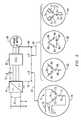
- FIG. 1is a block diagram representation of an example embodiment of a power system embodying aspects of the present invention.
- FIG. 2is a schematic representation including example embodiments of signal-conditioning circuitry (e.g., filter circuitry) that may be used in the power system of FIG. 1 .
- signal-conditioning circuitrye.g., filter circuitry
- FIG. 3is a schematic representation including example embodiments of signal-conditioning circuitry based on impedance matching that may be used in the power system of FIG. 1 .
- FIG. 4illustrates comparative plots of voltage waveforms for illustrating voltage spike reduction in accordance with aspects of the present invention.
- aspects of the present inventionmay be utilized in power systems, such as may be used for driving an electromotive traction system and auxiliary equipment through a common power bus.
- Example vehicular applications of the power systemmay be in locomotives, marine vessels, off-highway vehicles (as may be equipped with rubber tires, such as mining vehicles, agricultural vehicles) and transit vehicles.
- aspects of the inventionare described herein as it may be applied to a locomotive.
- FIG. 1is a block diagram schematic of an example embodiment of a power system 10 in accordance with aspects of the present invention.
- one or more traction motors (INV/TM) 22 and auxiliary equipment 39may be connected to a power source, such as a main alternator 16 , via a rectifier 15 that provides power to a common power bus 37 .
- the rectifier 15may be configured for converting the AC power generated by the main alternator 16 to DC power having a voltage sufficient for powering the traction motors 22 and provide the DC power to the common power bus 37 .
- Auxiliary equipment 38such as a radiator fan motor (RAD FAN) 40 , a traction motor blower (TM BLOW) 42 , other loads 46 , as may include an alternator blower (ALT BLOW) 48 , and an air compressor (COMP) 50 , may be connected to the bus 37 via respective DC to AC converters, or inverters 44 , such as pulse-width modulators (PWMs), that convert the DC power, made available on the bus 37 by the rectifier 15 , into AC power having a frequency and voltage independent of the AC power generated by the main alternator 16 .
- the main alternator 16is typically driven by a mechanical output 14 (e.g., crankshaft and transmission) of an engine 12 .
- the inventors of the present inventionhave recognized relatively inexpensive and uncomplicated signal-conditioning circuitry (SCC or S.C.C.) 60 and/or techniques that allow for the coupling of auxiliary equipment (e.g., auxiliary load) 39 to common power bus 37 having a voltage sufficiently high so that the traction motors may be operated at an example voltage range from approximately 1,000 volts to approximately 1500 volts.
- SCCsignal-conditioning circuitry
- auxiliary equipmente.g., auxiliary load
- the traction systemincludes one or more electromotive machines having a first type of stator windings (e.g., form-wound windings) configured to provide a level of protection relative to voltage spikes expected at the traction stator under a first voltage level appropriate for the traction system (e.g., from approximately 1000 volts to approximately 1500 volts). That is, the electromotive machine operates at (or around) the first voltage level, but may receive voltage spikes above the first voltage level, which are at least partially protected against by the stator windings.
- a first type of stator windingse.g., form-wound windings
- the auxiliary equipmentmay include one or more electromotive machines having a second type of stator winding (e.g., random-wound windings) configured to provide a level of protection relative to voltage spikes expected at the auxiliary stator when operating under a second voltage level lower than the first voltage level (e.g., from approximately 400 volts to approximately 750 volts).
- a second voltage levellower than the first voltage level (e.g., from approximately 400 volts to approximately 750 volts).
- the voltage spike attenuation provided by SCC 60is sufficient to protect the auxiliary stator notwithstanding operation of the power bus at the first voltage level.
- SCC 60comprises respective filters (e.g., low-pass filters (LPFs) or band-pass filters (BPFs) configured to suppress (e.g., attenuate) repetitive (e.g., recurring) voltage spikes produced under relatively high dV/dt conditions resulting from the switching operation of inverter drive circuitry, such as high-speed power switches, coupled to drive the equipment.
- filterse.g., low-pass filters (LPFs) or band-pass filters (BPFs) configured to suppress (e.g., attenuate) repetitive (e.g., recurring) voltage spikes produced under relatively high dV/dt conditions resulting from the switching operation of inverter drive circuitry, such as high-speed power switches, coupled to drive the equipment.
- LPFslow-pass filters
- BPFsband-pass filters
- SCC 60may be realized without the use of filters (or in combination with filters), as such circuitry may be realized through appropriate selection of the characteristics of interconnecting lines 62 ( FIG. 3 ) for interconnecting one or more auxiliary loads 39 to a given inverter 44 .
- the respective impedance of connecting lines 62 1 , 62 2 and 62 3may be selected to substantially match the impedance characteristics of the auxiliary load, and in this manner reduce the coefficient of reflection of the lines, which is conducive to reducing the magnitude of the voltage spikes produced under high dV/dt conditions.
- a typical switching speed of IGBTsas may be used in inverters, is approximately 10,000 Volts/microsecond.
- the signal conditioningmay be a combination of the above-described operations. For example a combination of at least two of a) filtering the signals from the inverter circuitry to the auxiliary equipment; b) establishing an impedance match between the auxiliary equipment and at least one line interconnecting the inverter circuitry and the auxiliary equipment; and c) adjusting a switching speed of a power switching device in the inverter circuitry.
- random-wound motorsin the auxiliary equipment 39 .
- random-wound motor windingscan be made at reduced costs over form-wound windings.
- the arrangement of random-wound windingsmay be more vulnerable to voltage spikes than form-wound windings.
- the winding turnsare arranged in a precise spatial arrangement relative to one another. For example, in a form-wound construction, turn one may be always next to turn two, turn two may be always next to turn three, and so on.
- the turnshave a random location and the wires in a given turn can be arranged next to any other turn.
- signal-conditioning circuitry 60allows one to couple random-wound motors on the same power bus for the traction motors.
- the signal-conditioning circuitrymay comprise an RLC-based (resistor/inductor/capacitor) filter (e.g., band-pass filter) arranged in a Y-circuit topology, as schematically illustrated in inset 70 in FIG. 2 .
- a respective inductor 72is in series circuit with a capacitor 73 and a resistor 74 with respect to the voltage spikes 75 .
- the signal-conditioning circuitrymay comprise an RC-based (resistor/capacitor) low-pass filter as schematically illustrated in respective insets 82 (Y-circuit topology) and 85 ( ⁇ -circuit topology, i.e., delta-circuit topology) in FIG. 2 .
- RC-based (resistor/capacitor) low-pass filteras schematically illustrated in respective insets 82 (Y-circuit topology) and 85 ( ⁇ -circuit topology, i.e., delta-circuit topology) in FIG. 2 .
- the filtering operationis primarily achieved by the low-reactance provided by capacitors 84 in combination with resistors 86 with respect to the voltage spikes 75 .
- capacitors 84operate as shorting elements with respect to such spikes.
- Inset 90illustrates an RLC-based low-pass filter also arranged in a Y-circuit topology.
- a respective inductor 72is in parallel circuit with a respective resistor 74 and this parallel circuit is series connected to a respective capacitor 73 .
- La line separation from the output side of auxiliary inverter 44 to the input side of auxiliary load 39 is a distance L, then it is contemplated that if one uses any of the filter topologies respectively illustrated insets 82 , 84 or 90 , then one example range for locating such filters may be from the input side of the auxiliary load to a distance L/2 upstream from the auxiliary load, as schematically represented by arrow 92 .
- the filter locationmay be up to about 15-20 feet from the auxiliary load, however, a preferred location may be as near as practical to the auxiliary load.
- the value of one or more of the filter elementsneed not be fully-based on the value of discrete components since, for example, one can estimate and/or model a reactance (capacitance or inductance) of any auxiliary load coupled to a given inverter, as well as the intrinsic reactance of a connecting line itself, and one can make use of the value of the load and intrinsic reactance for implementing at least some of the filter circuitry.
- the estimating and/or modeling of the load and intrinsic reactancemay be accomplished using any standard estimating and/or modeling tools, such as are commonly available and well-understood in the art of transmission line design.
- FIG. 4illustrates comparative example voltage waveforms plotted as a function of time, for illustrating voltage spike reduction in accordance with aspects of the present invention.
- Example waveform 96is representative of voltage spikes as may be produced in a power system under high dV/dt conditions without the benefits of signal conditioning circuit embodying aspects of the present invention. In one example power system application, voltage spikes in excess of 2400 V were observed.
- Example waveform 98is representative of voltage spikes as may be attenuated with a signal conditioning circuit (e.g., filter) embodying aspects of the present invention. Note that in this example application the voltage spikes are attenuated at least 25% relative to the voltage spikes in waveform 96 .
- a signal conditioning circuite.g., filter
- a filter or other circuitis “based” on one or more circuit elements, e.g., resistor/capacitor-based filter
- the filter or other circuitincludes at least one each of the stated circuit elements arranged to perform the stated function of the circuit, e.g., for a resistor/capacitor-based filter at least one resistor and at least one capacitor arranged to perform a filtering function.
- a common bus for the traction and auxiliary loadsis conducive to reducing (or avoiding) costs that otherwise would be incurred in a dual bus implementation, such as needing another stage of power & voltage conversion.
- using a common busis conducive to a desirable reduction of components.
- a common capacitor 41(and/or bus bar) can now be used to connect the auxiliary and the traction inverters through the common bus instead of separate capacitors and/or bus bars for two separate buses.
- capacitor 41may be interconnected across a first power rail 45 (e.g., positive rail) and a second power rail 96 (e.g., negative rail) of the power bus.
Landscapes
- Engineering & Computer Science (AREA)
- Power Engineering (AREA)
- Transportation (AREA)
- Mechanical Engineering (AREA)
- Life Sciences & Earth Sciences (AREA)
- Sustainable Development (AREA)
- Sustainable Energy (AREA)
- Inverter Devices (AREA)
- Electric Propulsion And Braking For Vehicles (AREA)
Abstract
Description
Claims (16)
Priority Applications (4)
| Application Number | Priority Date | Filing Date | Title |
|---|---|---|---|
| US12/333,611US7928597B2 (en) | 2008-12-12 | 2008-12-12 | Power system and method for driving an electromotive traction system and auxiliary equipment through a common power bus |
| CN200980156780.6ACN102317101B (en) | 2008-12-12 | 2009-11-20 | Power system and method of driving an electric traction system and auxiliary equipment via a common power bus |
| EP09765182AEP2376305A1 (en) | 2008-12-12 | 2009-11-20 | Power system and method for driving an electromotive traction system and auxiliary equipment through a common power bus |
| PCT/US2009/065226WO2010068386A1 (en) | 2008-12-12 | 2009-11-20 | Power system and method for driving an electromotive traction system and auxiliary equipment through a common power bus |
Applications Claiming Priority (1)
| Application Number | Priority Date | Filing Date | Title |
|---|---|---|---|
| US12/333,611US7928597B2 (en) | 2008-12-12 | 2008-12-12 | Power system and method for driving an electromotive traction system and auxiliary equipment through a common power bus |
Publications (2)
| Publication Number | Publication Date |
|---|---|
| US20100148581A1 US20100148581A1 (en) | 2010-06-17 |
| US7928597B2true US7928597B2 (en) | 2011-04-19 |
Family
ID=41611309
Family Applications (1)
| Application Number | Title | Priority Date | Filing Date |
|---|---|---|---|
| US12/333,611Expired - Fee RelatedUS7928597B2 (en) | 2008-12-12 | 2008-12-12 | Power system and method for driving an electromotive traction system and auxiliary equipment through a common power bus |
Country Status (4)
| Country | Link |
|---|---|
| US (1) | US7928597B2 (en) |
| EP (1) | EP2376305A1 (en) |
| CN (1) | CN102317101B (en) |
| WO (1) | WO2010068386A1 (en) |
Cited By (9)
| Publication number | Priority date | Publication date | Assignee | Title |
|---|---|---|---|---|
| US20090082915A1 (en)* | 2005-09-30 | 2009-03-26 | C.V.S., S.P.A. | Apparatus for transporting a load |
| US20110304199A1 (en)* | 2010-06-09 | 2011-12-15 | Rozman Gregory I | Hybrid electric power architecture for a vehicle |
| US20120292985A1 (en)* | 2011-05-16 | 2012-11-22 | Denso Corporation | Vehicular electric system |
| US20130193750A1 (en)* | 2010-05-06 | 2013-08-01 | General Electric Company | Powered distribution systems for powered rail vehicles |
| US8861145B2 (en) | 2012-07-19 | 2014-10-14 | Honeywell International Inc. | Circuit with motor driver spike suppression |
| US20140318410A1 (en)* | 2013-04-26 | 2014-10-30 | Progress Rail Services Corporation | Locomotive with variable power modules |
| US9118201B2 (en) | 2012-05-08 | 2015-08-25 | General Electric Company | Systems and methods for energy transfer control |
| US9296300B2 (en) | 2012-04-13 | 2016-03-29 | General Electric Company | Method and system for powering a vehicle |
| US20160347163A1 (en)* | 2015-05-28 | 2016-12-01 | Joy Global Longview Operations Llc | Systems, methods, and apparatuses for storing energy in a mining machine |
Families Citing this family (9)
| Publication number | Priority date | Publication date | Assignee | Title |
|---|---|---|---|---|
| US9007186B1 (en) | 2010-07-03 | 2015-04-14 | Best Energy Reduction Technologies, Llc | Method and apparatus for controlling power to a device |
| US9331524B1 (en)* | 2010-07-03 | 2016-05-03 | Best Energy Reduction Technologies, Llc | Method, system and apparatus for monitoring and measuring power usage |
| US9760140B1 (en) | 2010-07-03 | 2017-09-12 | Best Energy Reduction Technologies, Llc | Method, system and apparatus for monitoring and measuring power usage by a device |
| GB2483696B (en)* | 2010-09-17 | 2015-03-25 | Ge Aviat Systems Ltd | An aircraft with a power distribution system |
| CN104254470B (en) | 2012-03-15 | 2017-03-22 | 博瑞特储能技术公司 | Auxiliary power unit components and usage methods |
| JP5861614B2 (en)* | 2012-11-12 | 2016-02-16 | 株式会社デンソー | High voltage electric device and electric compressor |
| AU2014237461B2 (en)* | 2013-03-15 | 2017-12-07 | Bright Energy Storage Technologies, Llp | Apparatus and method for controlling a locomotive consist |
| US10042342B1 (en) | 2015-10-08 | 2018-08-07 | Best Energy Reduction Technologies, Llc | Monitoring and measuring power usage and temperature |
| US10530239B2 (en)* | 2018-03-05 | 2020-01-07 | Regal Beloit America, Inc. | Filter systems for reducing bearing current in high-frequency motor control systems |
Citations (26)
| Publication number | Priority date | Publication date | Assignee | Title |
|---|---|---|---|---|
| US4855891A (en)* | 1987-09-23 | 1989-08-08 | Eventide Inc. | Power supply design |
| US4896063A (en)* | 1986-08-27 | 1990-01-23 | S.P.C. Holding Co., Inc. | Electromagnetic induction devices with multi-form winding and reflected magnetizing impedance |
| US5258902A (en)* | 1992-05-11 | 1993-11-02 | Simmonds Precision Products, Inc. | Snubber circuit located between an output line and low impedance potential |
| US5481451A (en)* | 1992-10-30 | 1996-01-02 | Arex Electronics Corporation | AC-to-AC power inverter apparatus functioning without smoothing capacitor, and control method thereof |
| US6166929A (en)* | 2000-02-29 | 2000-12-26 | Rockwell Technologies, Llc | CSI based drive having active damping control |
| US6304013B1 (en) | 1999-06-30 | 2001-10-16 | General Electric Company | Line termination network assembly for an electric motor |
| US6366483B1 (en)* | 2000-07-24 | 2002-04-02 | Rockwell Automation Technologies, Inc. | PWM rectifier having de-coupled power factor and output current control loops |
| US20020096959A1 (en)* | 2000-11-02 | 2002-07-25 | Capstone Turbine Corporation | Transposed winding for random-wound electrical machines operating at high frequencies |
| US6441581B1 (en)* | 2001-03-20 | 2002-08-27 | General Electric Company | Energy management system and method |
| US6455971B1 (en)* | 1999-02-16 | 2002-09-24 | Aesop, Inc. | Method of winding motors and other electric machines to reduce AC losses |
| US6486568B1 (en)* | 1999-12-21 | 2002-11-26 | General Electric Company | Power system using a multi-functional power interface unit |
| US20030118891A1 (en) | 2001-12-12 | 2003-06-26 | Honda Giken Kogyo Kabushiki Kaisha | Temperature controlling apparatus for battery, vehicle apparatus using the same, and controlling method therefor |
| US6678972B2 (en)* | 2001-02-06 | 2004-01-20 | Komatsu Ltd. | Hybrid construction equipment |
| WO2004066492A1 (en) | 2003-01-20 | 2004-08-05 | Schaffner Emv Ag | Filter network |
| US6909200B2 (en)* | 2002-02-28 | 2005-06-21 | Azure Dynamics Inc. | Methods of supplying energy to an energy bus in a hybrid electric vehicle, and apparatuses, media and signals for the same |
| US20060025902A1 (en)* | 2004-07-23 | 2006-02-02 | Brown Herbert J | Secondary power for critical loads for railroad |
| US20060076171A1 (en)* | 2004-08-09 | 2006-04-13 | Donnelly Frank W | Regenerative braking methods for a hybrid locomotive |
| WO2006056235A1 (en) | 2004-11-24 | 2006-06-01 | Schaffner Emv Ag | Overshoot filter |
| US20060119177A1 (en) | 2004-12-02 | 2006-06-08 | Kumar Ajith K | Locomotive auxiliary power system |
| US20060127704A1 (en)* | 2004-12-10 | 2006-06-15 | Stephen Raiser | Hybrid fuel cell system with battery capacitor energy storage system |
| US7304445B2 (en)* | 2004-08-09 | 2007-12-04 | Railpower Technologies Corp. | Locomotive power train architecture |
| US20080087479A1 (en)* | 2006-10-11 | 2008-04-17 | Hyundai Motor Company | Power system of hybrid fuel cell bus and control method thereof |
| US7535116B2 (en)* | 2007-04-16 | 2009-05-19 | General Electric Company | System and method for controlling an output of an auxiliary power source of a diesel powered system |
| US7565867B2 (en)* | 2004-09-03 | 2009-07-28 | Frank Wegner Donnelly | Multiple engine locomotive configuration |
| US7573153B2 (en)* | 2005-12-23 | 2009-08-11 | Siemens Aktiengesellschaft | Power supply apparatus for field devices |
| US20090288577A1 (en)* | 2008-05-23 | 2009-11-26 | General Electric Company | Method and system for wind-harnessed battery charging in a locomotive |
- 2008
- 2008-12-12USUS12/333,611patent/US7928597B2/ennot_activeExpired - Fee Related
- 2009
- 2009-11-20CNCN200980156780.6Apatent/CN102317101B/ennot_activeExpired - Fee Related
- 2009-11-20EPEP09765182Apatent/EP2376305A1/ennot_activeWithdrawn
- 2009-11-20WOPCT/US2009/065226patent/WO2010068386A1/enactiveApplication Filing
Patent Citations (27)
| Publication number | Priority date | Publication date | Assignee | Title |
|---|---|---|---|---|
| US4896063A (en)* | 1986-08-27 | 1990-01-23 | S.P.C. Holding Co., Inc. | Electromagnetic induction devices with multi-form winding and reflected magnetizing impedance |
| US4855891A (en)* | 1987-09-23 | 1989-08-08 | Eventide Inc. | Power supply design |
| US5258902A (en)* | 1992-05-11 | 1993-11-02 | Simmonds Precision Products, Inc. | Snubber circuit located between an output line and low impedance potential |
| US5481451A (en)* | 1992-10-30 | 1996-01-02 | Arex Electronics Corporation | AC-to-AC power inverter apparatus functioning without smoothing capacitor, and control method thereof |
| US6455971B1 (en)* | 1999-02-16 | 2002-09-24 | Aesop, Inc. | Method of winding motors and other electric machines to reduce AC losses |
| US6304013B1 (en) | 1999-06-30 | 2001-10-16 | General Electric Company | Line termination network assembly for an electric motor |
| US6486568B1 (en)* | 1999-12-21 | 2002-11-26 | General Electric Company | Power system using a multi-functional power interface unit |
| US6166929A (en)* | 2000-02-29 | 2000-12-26 | Rockwell Technologies, Llc | CSI based drive having active damping control |
| US6366483B1 (en)* | 2000-07-24 | 2002-04-02 | Rockwell Automation Technologies, Inc. | PWM rectifier having de-coupled power factor and output current control loops |
| US20020096959A1 (en)* | 2000-11-02 | 2002-07-25 | Capstone Turbine Corporation | Transposed winding for random-wound electrical machines operating at high frequencies |
| US6678972B2 (en)* | 2001-02-06 | 2004-01-20 | Komatsu Ltd. | Hybrid construction equipment |
| US6441581B1 (en)* | 2001-03-20 | 2002-08-27 | General Electric Company | Energy management system and method |
| US20030118891A1 (en) | 2001-12-12 | 2003-06-26 | Honda Giken Kogyo Kabushiki Kaisha | Temperature controlling apparatus for battery, vehicle apparatus using the same, and controlling method therefor |
| US6909200B2 (en)* | 2002-02-28 | 2005-06-21 | Azure Dynamics Inc. | Methods of supplying energy to an energy bus in a hybrid electric vehicle, and apparatuses, media and signals for the same |
| WO2004066492A1 (en) | 2003-01-20 | 2004-08-05 | Schaffner Emv Ag | Filter network |
| US20060025902A1 (en)* | 2004-07-23 | 2006-02-02 | Brown Herbert J | Secondary power for critical loads for railroad |
| US20060076171A1 (en)* | 2004-08-09 | 2006-04-13 | Donnelly Frank W | Regenerative braking methods for a hybrid locomotive |
| US7304445B2 (en)* | 2004-08-09 | 2007-12-04 | Railpower Technologies Corp. | Locomotive power train architecture |
| US7565867B2 (en)* | 2004-09-03 | 2009-07-28 | Frank Wegner Donnelly | Multiple engine locomotive configuration |
| WO2006056235A1 (en) | 2004-11-24 | 2006-06-01 | Schaffner Emv Ag | Overshoot filter |
| US20060119177A1 (en) | 2004-12-02 | 2006-06-08 | Kumar Ajith K | Locomotive auxiliary power system |
| US7256513B2 (en) | 2004-12-02 | 2007-08-14 | General Electric Company | Locomotive auxiliary power system |
| US20060127704A1 (en)* | 2004-12-10 | 2006-06-15 | Stephen Raiser | Hybrid fuel cell system with battery capacitor energy storage system |
| US7573153B2 (en)* | 2005-12-23 | 2009-08-11 | Siemens Aktiengesellschaft | Power supply apparatus for field devices |
| US20080087479A1 (en)* | 2006-10-11 | 2008-04-17 | Hyundai Motor Company | Power system of hybrid fuel cell bus and control method thereof |
| US7535116B2 (en)* | 2007-04-16 | 2009-05-19 | General Electric Company | System and method for controlling an output of an auxiliary power source of a diesel powered system |
| US20090288577A1 (en)* | 2008-05-23 | 2009-11-26 | General Electric Company | Method and system for wind-harnessed battery charging in a locomotive |
Non-Patent Citations (6)
| Title |
|---|
| "Engineering Electromagnetic Fields and Waves", Chapter 10, Analysis of Reflective Transmission Lines, Carl T.A. Johnk, Copyright 1975, by John Wiley & Sons, Inc. |
| "Instructions for use of wound rotor motors with AC inverters" Drivecon Motor Drives EMD Comtrols, www.drivecon.com, WDRTMTR.p. 65, Sep. 12, 2002. |
| "Output filters for PWM Drives" GE Capacitors and Power Quality Products, New York, www.geindustrial.com/industrialsystems/products/capacitors.shtml. |
| "Riding the Reflected Wave-IGBT Drive Technology Demands New Motor and Cable Considerations", IEEE IAS-Petroleum & Chemical Industry Conference, Philadelphia, PA., Sep. 23-25, 1996 pp. 75-84. |
| "Riding the Reflected Wave—IGBT Drive Technology Demands New Motor and Cable Considerations", IEEE IAS-Petroleum & Chemical Industry Conference, Philadelphia, PA., Sep. 23-25, 1996 pp. 75-84. |
| "Surge Related Partial Discharges Resulting from IFDs Applied to Random Wound Motors", Mark Fenger, Blake Lloyd, Iris Power Engineering Inc., Toronto, Canada; Jan Pedersen, Techwise A/S, Fredericia, Denmark, Apr. 7, 2002. |
Cited By (16)
| Publication number | Priority date | Publication date | Assignee | Title |
|---|---|---|---|---|
| US20090082915A1 (en)* | 2005-09-30 | 2009-03-26 | C.V.S., S.P.A. | Apparatus for transporting a load |
| US20130193750A1 (en)* | 2010-05-06 | 2013-08-01 | General Electric Company | Powered distribution systems for powered rail vehicles |
| US8772962B2 (en)* | 2010-05-06 | 2014-07-08 | General Electric Company | Powered distribution systems for powered rail vehicles |
| US20110304199A1 (en)* | 2010-06-09 | 2011-12-15 | Rozman Gregory I | Hybrid electric power architecture for a vehicle |
| US8536729B2 (en)* | 2010-06-09 | 2013-09-17 | Hamilton Sundstrand Corporation | Hybrid electric power architecture for a vehicle |
| US20120292985A1 (en)* | 2011-05-16 | 2012-11-22 | Denso Corporation | Vehicular electric system |
| US9126485B2 (en)* | 2011-05-16 | 2015-09-08 | Denso Corporation | Vehicular electric system |
| US9296300B2 (en) | 2012-04-13 | 2016-03-29 | General Electric Company | Method and system for powering a vehicle |
| US9118201B2 (en) | 2012-05-08 | 2015-08-25 | General Electric Company | Systems and methods for energy transfer control |
| US8861145B2 (en) | 2012-07-19 | 2014-10-14 | Honeywell International Inc. | Circuit with motor driver spike suppression |
| US20140318410A1 (en)* | 2013-04-26 | 2014-10-30 | Progress Rail Services Corporation | Locomotive with variable power modules |
| US20160347163A1 (en)* | 2015-05-28 | 2016-12-01 | Joy Global Longview Operations Llc | Systems, methods, and apparatuses for storing energy in a mining machine |
| US9873318B2 (en)* | 2015-05-28 | 2018-01-23 | Joy Global Longview Operation LLC | Systems, methods, and apparatuses for storing energy in a mining machine |
| US10377225B2 (en) | 2015-05-28 | 2019-08-13 | Joy Global Longview Operations Llc | Systems, methods, and apparatuses for storing energy in a mining machine |
| US10449849B2 (en) | 2015-05-28 | 2019-10-22 | Joy Global Longview Operations Llc | Mining machine and energy storage system for same |
| US11084367B2 (en) | 2015-05-28 | 2021-08-10 | Joy Global Longview Operations Llc | Mining machine and energy storage system for same |
Also Published As
| Publication number | Publication date |
|---|---|
| US20100148581A1 (en) | 2010-06-17 |
| CN102317101A (en) | 2012-01-11 |
| CN102317101B (en) | 2014-07-09 |
| WO2010068386A1 (en) | 2010-06-17 |
| EP2376305A1 (en) | 2011-10-19 |
Similar Documents
| Publication | Publication Date | Title |
|---|---|---|
| US7928597B2 (en) | Power system and method for driving an electromotive traction system and auxiliary equipment through a common power bus | |
| US6486568B1 (en) | Power system using a multi-functional power interface unit | |
| US7764042B2 (en) | Inverter-driven rotating machine system, rotating machine and inverter used in the same and electric vehicle using the same | |
| WO2011010687A1 (en) | Semiconductor element controller and in-vehicle electric system | |
| CN1156522A (en) | Component Layout for Improved EMI Filters for Power Converters | |
| US9142955B2 (en) | Method and system for fault protection | |
| CN102195411A (en) | Electrical machines with integrated power and control and including a current source inverter | |
| CN107681884B (en) | Automobile air conditioner compressor and automobile | |
| CN110719036A (en) | Power conversion system, filter and method for reducing voltage stress on motor cable | |
| CN112737356A (en) | High-power permanent-magnet direct-drive freight locomotive traction converter | |
| US8971079B2 (en) | Inverter device | |
| US11398773B2 (en) | Filter for power train | |
| JP3780949B2 (en) | Power converter | |
| JP4803928B2 (en) | Power converter | |
| WO2025140509A1 (en) | Train control system | |
| CN112838750B (en) | Active common mode cancellation | |
| Murthy-Bellur et al. | WBG inverter for commercial power generation and vehicle electrification | |
| JP2002315101A (en) | Electric vehicle drive control device | |
| CN112889211A (en) | Power conversion device | |
| JP2015061397A (en) | Main circuit device and railway vehicle | |
| WO2019021128A1 (en) | A load dump | |
| JPH07298642A (en) | Power converter | |
| JPH09168208A (en) | Electric vehicle electrical system | |
| CN219420573U (en) | Filter and motor driving system | |
| CN215956289U (en) | Driving device and driving motor system |
Legal Events
| Date | Code | Title | Description |
|---|---|---|---|
| AS | Assignment | Owner name:GENERAL ELECTRIC COMPANY,NEW YORK Free format text:ASSIGNMENT OF ASSIGNORS INTEREST;ASSIGNORS:GUPTA, SUDHIR KUMAR;KUMAR, AJITH KUTTANNAIR;WORDEN, BRET DWAYNE;AND OTHERS;REEL/FRAME:021971/0331 Effective date:20081124 Owner name:GENERAL ELECTRIC COMPANY, NEW YORK Free format text:ASSIGNMENT OF ASSIGNORS INTEREST;ASSIGNORS:GUPTA, SUDHIR KUMAR;KUMAR, AJITH KUTTANNAIR;WORDEN, BRET DWAYNE;AND OTHERS;REEL/FRAME:021971/0331 Effective date:20081124 | |
| FEPP | Fee payment procedure | Free format text:PAYOR NUMBER ASSIGNED (ORIGINAL EVENT CODE: ASPN); ENTITY STATUS OF PATENT OWNER: LARGE ENTITY | |
| STCF | Information on status: patent grant | Free format text:PATENTED CASE | |
| FPAY | Fee payment | Year of fee payment:4 | |
| MAFP | Maintenance fee payment | Free format text:PAYMENT OF MAINTENANCE FEE, 8TH YEAR, LARGE ENTITY (ORIGINAL EVENT CODE: M1552); ENTITY STATUS OF PATENT OWNER: LARGE ENTITY Year of fee payment:8 | |
| AS | Assignment | Owner name:GE GLOBAL SOURCING LLC, CONNECTICUT Free format text:ASSIGNMENT OF ASSIGNORS INTEREST;ASSIGNOR:GENERAL ELECTRIC COMPANY;REEL/FRAME:047736/0140 Effective date:20181101 | |
| FEPP | Fee payment procedure | Free format text:MAINTENANCE FEE REMINDER MAILED (ORIGINAL EVENT CODE: REM.); ENTITY STATUS OF PATENT OWNER: LARGE ENTITY | |
| LAPS | Lapse for failure to pay maintenance fees | Free format text:PATENT EXPIRED FOR FAILURE TO PAY MAINTENANCE FEES (ORIGINAL EVENT CODE: EXP.); ENTITY STATUS OF PATENT OWNER: LARGE ENTITY | |
| STCH | Information on status: patent discontinuation | Free format text:PATENT EXPIRED DUE TO NONPAYMENT OF MAINTENANCE FEES UNDER 37 CFR 1.362 | |
| FP | Lapsed due to failure to pay maintenance fee | Effective date:20230419 |