US7927240B2 - Lighted archery nock with variable light emissions - Google Patents
Lighted archery nock with variable light emissionsDownload PDFInfo
- Publication number
- US7927240B2 US7927240B2US12/249,205US24920508AUS7927240B2US 7927240 B2US7927240 B2US 7927240B2US 24920508 AUS24920508 AUS 24920508AUS 7927240 B2US7927240 B2US 7927240B2
- Authority
- US
- United States
- Prior art keywords
- arrow
- nock
- light source
- battery
- lighted
- Prior art date
- Legal status (The legal status is an assumption and is not a legal conclusion. Google has not performed a legal analysis and makes no representation as to the accuracy of the status listed.)
- Active, expires
Links
Images


Classifications
- F—MECHANICAL ENGINEERING; LIGHTING; HEATING; WEAPONS; BLASTING
- F21—LIGHTING
- F21V—FUNCTIONAL FEATURES OR DETAILS OF LIGHTING DEVICES OR SYSTEMS THEREOF; STRUCTURAL COMBINATIONS OF LIGHTING DEVICES WITH OTHER ARTICLES, NOT OTHERWISE PROVIDED FOR
- F21V33/00—Structural combinations of lighting devices with other articles, not otherwise provided for
- F21V33/008—Leisure, hobby or sport articles, e.g. toys, games or first-aid kits; Hand tools; Toolboxes
- F—MECHANICAL ENGINEERING; LIGHTING; HEATING; WEAPONS; BLASTING
- F42—AMMUNITION; BLASTING
- F42B—EXPLOSIVE CHARGES, e.g. FOR BLASTING, FIREWORKS, AMMUNITION
- F42B6/00—Projectiles or missiles specially adapted for projection without use of explosive or combustible propellant charge, e.g. for blow guns, bows or crossbows, hand-held spring or air guns
- F42B6/02—Arrows; Crossbow bolts; Harpoons for hand-held spring or air guns
- F42B6/04—Archery arrows
- F42B6/06—Tail ends, e.g. nocks, fletching
Definitions
- the present inventionrelates to archery arrow nocks with a light-emitting feature, commonly referred to as illuminated or lighted nocks.
- Simontondiscloses an illuminated arrow nock that is activated by a magnetic field.
- the arrow nockincludes a normally open magnetic reed switch connected to a battery, circuitry, a light and a riser magnet that must be mounted to a riser of a bow from which the arrow is shot.
- the normally open magnetic reed switchpasses through the magnetic field of the riser magnet, which closes the magnetic reed switch, which completes the circuit between the battery and the light to illuminate the light.
- the circuitryalso includes a capacitor which discharges to eventually interrupt the circuit between the battery and the light after a predetermined amount of time.
- the circuitrycan also include a processor that pulses or blinks the light after being actuated by the reed switch.
- Simontonprovides an illuminated nock, it provides added complexity and opportunity for system failure by requiring the nock to pass through the magnetic field of the riser magnet. Further, due to the light automatically de-powering after a programmed amount of time, archers sometimes must search for the arrow under pressure, knowing that the light may soon de-power.
- Takahashidiscloses an illuminated nock that includes an electrical circuit that has a normally open acceleration switch, a capacitor circuit, a battery and an LED.
- the acceleration switchincludes two thin metal plates, which are separated by a distance. When the arrow is shot from a bow, the thin plates bend and contact one another, thereby completing the circuit between the battery and the LED to light the LED and charge the capacitor circuit. After the arrow reaches constant speed, the metal plates separate so power is no longer provided from the battery to the LED. The capacitor, however, continues to provide its charge to the LED. After a predetermined amount time, however, the charge of the capacitor is depleted, and the LED de-powered. Like Simonton, due to the light automatically de-powering after a predetermined amount of time, archers sometimes must search for the arrow under pressure, knowing that the light may soon de-power.
- nocks of the above referencesprovide desired illumination, they suffer the noted shortcomings.
- these referencesinclude holders for the related batteries, these holders sometimes may not adequately retain the battery, and may also render battery replacement very difficult, which is unappealing to consumers.
- the present inventionprovides an archery arrow nock including an accelerometer, a power source, a light and an optional controller that controls the illumination of the light.
- the controllercan be a microprocessor that performs one or more functions, such as: monitoring the accelerometer, controlling the timing of the light emitting cycle of the light, and responding to input by a user, for example, to reset the light.
- the archery nockis joined with an arrow adapted for shooting from an archery bow.
- the archery nockincludes an accelerometer, which can be a mechanical acceleration switch and/or an integrated circuit accelerometer.
- the accelerometercan be actuated by accelerating the arrow, for example, when the arrow is shot from the archery bow.
- the accelerometercan generate or provide a signal or accelerometer output indicative of the acceleration of the arrow or arrow nock to the microprocessor.
- the microprocessorilluminates the light as a function of the accelerometer output, for example by completing a circuit between the battery and the light.
- the power sourcecan be a DC-DC power supply, such as a lithium battery, and the light can be a light emitting diode (LED), filament light, or other light source.
- LEDlight emitting diode
- the microprocessorcan account for a phenomenon referred to as a “blind spotting”, which results when the nock is illuminated immediately upon release of the arrow, causing the archer to be temporarily blinded by that illumination in the corner of the eye.
- the microprocessorcan illuminate the light after a predetermined time interval after release of the arrow to prevent blind spotting.
- the microprocessorcan PWM (Pulse Width Modulate) the LED to conserve battery life by turning it on and off at a frequency that is not perceptible to the human eye.
- the rate or other variables of the PWMcan be controlled as a function of the accelerometer output.
- the microprocessor or circuitrycan be programmed or wired to minimize battery drain, thereby improving battery life.
- the lighted nock assemblycan receive input from a user. This input can be transferred through the accelerometer and/or another sensor associated with the nock.
- the accelerometer or other sensorcan detect acceleration or deceleration along axes other than the longitudinal axis of the nock, which is generally aligned with the longitudinal axis of an arrow.
- the microprocessorcan respond to this information to perform the user's desired functionality. Accordingly, when a user moves the nock, for example, taps the nock against an object, the accelerometer or other sensor can detect this movement, and send a signal to the microprocessor.
- the term tapis used to convey moving the arrow nock in a direction other than longitudinal with the arrow and does not require the arrow or arrow nock assembly to touch another object—mere movement of the arrow or arrow nock assembly sufficient to register an accelerometer output in a direction other than generally longitudinal with the arrow is sufficient.
- the microprocessorupon detecting the signal, can operate the light of other components of the nock.
- the microprocessormay be programmed to respond to the accelerometer output in a variety of different ways. For example, depending on the amount of deceleration or acceleration detected by the accelerometer, the microprocessor may be programmed to do one or more of the following: turn off the light, turn on the light, blink the light, blink the light fast, blink the light slow, pulse width modulate the light to save battery power, blink the light at a predetermined speed or range of speeds, blink the light after the arrow stops so an archer can find the arrow, or operate the light or other archery nock component in some other way.
- the microprocessormay also be programmed to recognize successive accelerometer output. For example, in some embodiments, the microprocessor can recognize and distinguish between one, two, three or more taps of the arrow nock and perform a different function in response to each. The microprocessor can recognize the number of taps by identifying a particular pattern in the accelerometer output. In one embodiment, predefined time intervals and thresholds allow identification of successive taps of the arrow.
- the microprocessormay be programmable by tapping the nock. A particular number of successive taps can prompt the controller to enter a programming mode. During the programming mode, the user can program the nock to perform whatever functionality the user desires. For example, the user can program the microprocessor to perform specific functions in response to one, two, three or more taps. In one embodiment, upon entering programming mode, the microprocessor is pre-programmed with a number of different functionalities that the user may select. For example, the programming mode may allow the user to determine the speed at which the light blinks by having the light blink at a range of different speeds until the user taps the nock, where tapping the nock selects the current speed of blink. Other characteristics that may be programmed include, but are not limited to, brightness of the light, blindspot time, shutoff time, and any other programmable lighted archery nock variable.
- the microprocessorcan be programmed to cause the light to blink perceptibly at some predetermined time after arrow launch, and then turn it off after another predetermined time to conserve the power source, for example, the life of a battery.
- the microprocessorinstead of blinking perceptibly at some predetermined time after arrow launch, can be programmed to cause the light to blink perceptibly in response to determining that the arrow has come to a rest.
- the microprocessorcan be programmed to monitor the accelerometer and prevent false activation of the light if the arrow is accidentally dropped.
- the predetermined timemay be programmed in the field by the user using the programmable mode described above.
- the power sourcecan be a battery, and the battery can be replaceable relative to the nock.
- the nockcan include circuitry, such as a circuit board to which the other components, such as the accelerometer, microprocessor and light are joined.
- the circuit boardcan include contacts or terminals which engage the battery.
- the nockcan also include a housing or other element that engages the battery to ensure that the battery maintains contact with the circuit board terminals or contacts.
- the batterycan include an annular groove
- the housingcan include tabs that engage the annular groove on the battery.
- the annular battery groovecan include any annular recess or any other battery interface that interfits with the housing tabs.
- the housing tabscan include fingers or any other housing interface that interfits with the battery annular groove.
- an “O” ring or other spacercan be placed on a peripheral surface of the battery to facilitate centering the unit in the inside diameter of the arrow shaft.
- the circuit boardmay be constructed with tabs or projections extending from it where the two are adapted to engage the arrow nock and/or the battery housing.
- the tabscan be included on edges of the board.
- the tabscan engage corresponding holes, such as slots, in the housing.
- the nockcan be constructed with internal projections that define one or more slots which engage the edges of the circuit board.
- the edgescan be retained with an adhesive, such as silicon.
- a nock with a smooth internal borecan be used. There, retention can be achieved by a device inserted through holes aligned in the nock and the circuit board, such as a pin. Even further optionally, an adhesive can be applied to provide retention of the pin or other device.
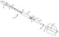
- FIG. 1is an exploded view of a nock assembly of the current embodiment of the invention.
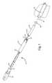
- FIG. 2is a plan view of the nock assembly of FIG. 1 .
- FIG. 3is a top view of the circuit board of the nock assembly of FIG. 1 .
- FIG. 4is in exploded partial view of the housing 30 and the battery 20 of the nock assembly of FIG. 1 .
- FIG. 5is a view of an alternative embodiment of a circuit board.
- FIG. 6is perspective view of an alternative embodiment of an archery nock.
- FIG. 7is an assembled view of an alternative embodiment of the nock assembly.
- FIG. 8is an exploded view of the nock assembly of FIG. 7 .
- FIG. 9is a cross-sectional view of the junction between the archery nock of claim 6 and a circuit board.
- the nock assembly 1generally includes a housing 30 , which secures or houses the circuit board 10 .
- the housing 30may secure or house the arrow nock 50 in addition to or in lieu of the circuit board.
- the nock 50can be constructed from a polymer, such as polycarbonate, metals, or any other materials as desired.
- the nockcan also be translucent or transparent so that light produced by the light 60 can be transmitted therethrough.
- the nock 50can further define a bore 52 into which the light 60 is fitted. In alternative embodiments, the light 60 may be positioned elsewhere on or in the nock assembly 1 .
- the contacts or terminals of the replaceable battery and the circuit boardare axially configured.
- One contact 25 of the replaceable battery 20which can be in the form of a pin or male terminal along the axis A, plugs into the circuit board contact 26 , which can be in the form of a bore or female terminal along the axis A, of the circuit board 10 at the end opposite the light 60 .
- the other contact 27 of the battery 20which can be in the form of a surface, can be engaged by the other circuit board contact 28 , which can be in the form of a pin or male terminal located radially from the bore 26 .
- circuit board contact 28may be in the form of a biasing member, such as a spring 14 in electrical communication with the printed circuit board.
- the springcan be a coil spring that at least partially encircles a portion of the battery 20 .
- Other types of contacts that enable selectable electrical communication between the replaceable battery and the circuit boardmay be implemented.
- the circuit boardmay be eliminated and the light source may have electrical contacts that allow it to directly interface with the replaceable battery.
- An “O” ring 40can encircle the battery 20 and serves to maintain the centrality of the battery 20 inside of the arrow shaft 70 .
- One suitable battery for use with the present inventionis a conventional fishing float pin type battery.
- Such batteriescan be 3.0V, and lithium based. These batteries are available from a variety of manufacturers and generally identified as CR425 batteries. Other batteries may be used as desired.
- the housingcan include latching fingers or tabs 32 on the front of the housing 30 .
- These tabs 32can be joined with the remainder of the housing, and can define a battery holding aperture 34 into which the battery 20 is at least partially inserted.
- the tabscan include an elongate finger portion 33 , which terminates at an inwardly protruding end projection 35 ( FIG. 4 ).
- the elongate finger portion 33can extend away from the housing, along the longitudinal axis A, and can be a desired width.
- each resilient tabcan be of an arcuate cross section, generally concentric with the axis A.
- the elongate finger portioncan resiliently flex relative to the main body portion 37 , outward, and away from the axis A.
- the projection 35can be configured to rest within a groove of the battery 20 .
- the tabs 32can be resilient and/or deformable so that they open slightly upon insertion of the battery into the aperture, but return to their former position to engage the annular recess 22 of the battery 20 . This engagement retains the battery 20 and restrict its movement along the axis of the arrow, even when the arrow impacts a target.
- the battery 20is readily replaceable in the field, after first removing the complete nock assembly 1 from the arrow, by lifting the latching tabs 32 and/or pulling the battery 20 forward so that it is removed from the battery holding aperture 34 . In this process, one contact 25 is removed from the bore 26 , and the other contact 27 disengages the circuit board terminal 28 . Replacement with a new battery is accomplished by simply reversing the process after ensuring that the “O” ring 40 is in place on the battery 20 . Of course, other members, such as bands or spacers can substitute the “O” ring as desired. Specifically, the battery can be replaced by a user lifting the latching tabs or pulling the drained battery with sufficient force to disengage the latching tabs from the groove of the drained battery.
- the usercan insert a charged battery defining an annular groove into the archery nock assembly.
- the multiple latching tabscan deform, optionally bending radially outward, away from the axis A, to allow continued insertion of the charged battery. Thereafter, the latching tabs can return to their former position, engaging the annular recess of the charged battery.
- the circuit board 10is more detailed in FIG. 3 and FIG. 4 , which depict the LED power supply 103 , the microprocessor 101 , the LED 60 and the battery 20 .
- the various componentsare shown in their approximate relationship on the circuit board, but can be altered as desired.
- the circuit board 10includes circuits which couple the various components of the assembly to enable electrical communication to or through the components to light and control the light 60 in a desired manner. Electrical communication includes, but Is not limited to, direct or indirect electrical coupling or electrical connection of either power, control signals, or any other electrical signal.
- each individual componentcan be positioned so that its center of mass is positioned on the axis A. In this manner, the nock assembly 1 is well balanced, and will not cause the arrow to which it is joined to fly erratically.
- the microprocessorcan be programmed to minimize battery drain, and therefore preserve battery life.
- the microprocessorcan pulse width modulate the LED. Due to the human eye's visual persistence, the modulation may not be visually detected. Nonetheless, operation in such a mode can result in power savings which can greatly extend the life of the battery.
- Pulse width modulation as used hereincan encompass duty cycle modulation, or any other technique to control the amount of power transmitted to a load. Pulse width modulation may also be used to achieve an apparent higher brightness for a given power input. For example, the human eye tends to perceive peak current light levels rather than average current light levels when modulation rate of a light is higher than approximately 1000 hertz and the duty cycle is greater than 15 to 20%.
- the microprocessorcan be programmed to turn the LED on and off at predetermined, longer intervals after the arrow is shot.
- the accelerometeralso can be located on the axis A.
- This accelerometercan be an acceleration switch or an integrated circuit accelerometer. Functionally, both respond to the force resulting from the acceleration of the arrow upon release.
- the accelerometercan be configured to sense acceleration and/or deceleration along the axis A; however, the accelerometer can also be configured to sense acceleration or deceleration on other axes as desired.
- the switchcan be a miniature mechanical switch, either normally open or normally closed, and can respond to the application the G-force described above, or more generally to acceleration or deceleration.
- the switchis designed and sized to fit within an aperture defined by the circuit board 10 or on the surface of the circuit board.
- the mass of the switchalso can be equally distributed about the centerline through the plane of the circuit board congruent with axis A of the arrow.
- Exemplary, but non-limiting suitable acceleration switchesare disclosed in U.S. Pat. Nos. 7,326,867; 7,326,866; 7,067,748, as well as U.S. Provisional Patent Application 61/033,865, which are all hereby incorporated by reference in its entirety.
- acceleration switchis an acceleration sensor offered under the SQ-ASX, SQ,-ASA, SQ-ASB and SQ-ASD Series, which are commercially available from SignalQuest of Riverside, N.H. Other acceleration switches may be used as desired.
- the switchcan be mounted on a surface of the circuit board 10 , rather than in a hole defined by the board.
- the accelerometeris an integrated circuit accelerometer
- that accelerometercan be mounted on the circuit board in a somewhat different configuration such that the combined mass of the circuit board components is balanced about its axis.
- the accelerometer's response to the aforementioned G-forceis primarily electrical rather than mechanical.
- the devicecan be used to detect a G-force exerted on the nock of about 100 Gs to about 600 Gs, and can send a signal that such a G-force has been exerted on the nock to the microprocessor so that the microprocessor can activate the LED accordingly.
- the accelerometeris triggered by the G forces that accompany firing a bow at a speed of about 200 to 400 feet per second.
- the devicealso can be able to detect G-forces of about 0.1 Gs to about 10 Gs to determine when a user taps or engages the nock.
- the nockcan include a buffering system, such as an elastomer joined therewith, which buffers the total G-force exerted on the acceleration device.
- the acceleration devicemay be rated only to operate in a range of about 5 to about 20 Gs.
- the buffering systemreduces the Gs transferred to the acceleration device to between about 5 to about 20 Gs, thereby enabling the device to effectively detect the 100-600 Gs, but not be overloaded by the same high G-force.
- the controllerwhich may, for example, be a microprocessor, can receive input from a user. This input can be transferred through the accelerometer and/or another sensor associated with the nock.
- the accelerometer or other sensorcan detect acceleration or deceleration along axes other than the longitudinal axis of the nock, which is generally aligned with the longitudinal axis of an arrow. These other axes can be axes that radiate outward from the longitudinal axis, for example, orthogonally from the longitudinal axes, or other axes. Accordingly, when a user moves the nock, for example, taps the nock against an object, the accelerometer or other sensor can detect this movement, and send a signal to the microprocessor. The microprocessor, upon detecting the signal, can operate the light of other components of the nock.
- tapping an arrowis to hold the arrow by one end and swing the other end of the arrow in an arc.
- Thisprovides acceleration and/or deceleration along an axis other than the longitudinal axis of the arrow.
- Movement of the arrowgenerally includes movement of all of the arrow nock assembly, including the arrow nock and any other arrow nock components. Comparing the acceleration or deceleration of the movement of the nock or arrow against a predefined threshold allows the microprocessor to determine whether or not the movement amounts to a tap.
- the thresholdmay be set high so that it is difficult to accidentally tap the arrow. Alternatively, the threshold may be set low so that it is easier to tap the arrow.
- a thresholdmay be set based on acceleration, in other embodiments the threshold may be set based on deceleration, in yet other embodiments both acceleration and deceleration thresholds may be set. In some embodiments, multiple thresholds may be set.
- the microprocessorcan detect when the nock or arrow is tapped a particular number of times by a user, and/or in a particular sequence, and accordingly, can discontinue illumination of the light. This can allow the archer to turn off the light when the arrow is retrieved.
- the reset function parametersi.e. the number of taps and the interval between taps, is configurable in the initial programming of the microprocessor.
- the microprocessorcan detect when the nock or arrow is tapped a particular number of times by a user, and/or in a particular sequence, and accordingly, can set the light to actuate continuously, in a PWM mode, in another intermittent mode, or in other modes.
- the embodiments described abovecan feature a method of battery retention that ensures ease of battery replacement.
- the nock 50 of the nock assembly, or the light 60can be constructed to provide an aesthetic or visual effect.
- the light 60can be an LED or other light that emits light blue in color, for example, at a wavelength interval between 430 and 510 nm, optionally between 450 and 490 nm, and further optionally at 470 nm.
- the nockcan be translucent or transparent, and can transmit light from the light so that the nock 50 appears blue in color, for example, at a wavelength interval between 430 and 510 nm, optionally between 450 and 490 nm, and further optionally at 470 nm.
- FIGS. 7 and 8show an alternative embodiment of the arrow nock assembly described above.
- the arrow nock assemblyis similar to the arrow nock assembly described in connection with FIG. 1 .
- circuit board contact 28is in the form of a spring in electrical communication with the printed circuit board.
- the springcan physically engage the battery 20 , and can provide assistance for keeping the battery in place.
- the springcan urge the battery rim 29 out from the housing to firmly lock the projections against the electrode side of the groove 22 . This can provide added securement of the battery and/or reduce excessive vibration as desired.
- FIG. 5shows an optional configuration of the circuit board 10 depicting tabs 11 projecting from the edges of the circuit board 10 .
- the tabcan be designed to engage corresponding slots or openings 12 in the nock 50 and/or battery housing 30 .
- the tabs 11can be used to attach the circuit board 10 to the housing 30 .
- the circuit boardcan be bonded to the interior surface of the opening 52 in the nock 50 with silicone or other suitable adhesive so that the housing 30 is generally not removable from the board. Operation of these tabs 11 interfitting within the slots 12 can be seen in FIGS. 7 and 8 .
- FIG. 9illustrates in yet another embodiment, including an alternative construction to join the nock, or optionally the battery housing, with the circuit.
- projections 54are formed on the interior surface of the opening 52 of the nock 50 (or alternatively, the battery housing) to provide grooves 53 , which are optionally in an opposing configuration.
- the opposed edges of the circuit board 10fit within and engage the grooves 53 of the nock 50 .
- the nock and/or housing attachment elementscan be joined with the circuit board via silicone or other suitable adhesive 13 , as shown in the cross-sectional view of the junction between the circuit board and the archery nock, depicted in FIG. 9 .
- the nock assembly 1may be provided with a nock 50 defining an opening 52 with a smooth bore. Corresponding aligned holes can be defined in the nock 50 and the circuit board 10 .
- a devicesuch as a pin, can be inserted in the holes to retain the circuit board 10 in the nock 50 .
- a suitable adhesivemay be injected through the hole in the nock 50 .
Landscapes
- Engineering & Computer Science (AREA)
- General Engineering & Computer Science (AREA)
- Battery Mounting, Suspending (AREA)
- Arrangement Of Elements, Cooling, Sealing, Or The Like Of Lighting Devices (AREA)
- Toys (AREA)
Abstract
Description
Claims (20)
Priority Applications (1)
| Application Number | Priority Date | Filing Date | Title |
|---|---|---|---|
| US12/249,205US7927240B2 (en) | 2007-10-10 | 2008-10-10 | Lighted archery nock with variable light emissions |
Applications Claiming Priority (3)
| Application Number | Priority Date | Filing Date | Title |
|---|---|---|---|
| US99836207P | 2007-10-10 | 2007-10-10 | |
| US8090508P | 2008-07-15 | 2008-07-15 | |
| US12/249,205US7927240B2 (en) | 2007-10-10 | 2008-10-10 | Lighted archery nock with variable light emissions |
Publications (2)
| Publication Number | Publication Date |
|---|---|
| US20090097239A1 US20090097239A1 (en) | 2009-04-16 |
| US7927240B2true US7927240B2 (en) | 2011-04-19 |
Family
ID=40534003
Family Applications (3)
| Application Number | Title | Priority Date | Filing Date |
|---|---|---|---|
| US12/249,205Active2029-12-08US7927240B2 (en) | 2007-10-10 | 2008-10-10 | Lighted archery nock with variable light emissions |
| US12/249,210Active2029-12-15US7931550B2 (en) | 2007-10-10 | 2008-10-10 | Programmable lighted archery nock |
| US12/249,202Expired - Fee RelatedUS7993224B2 (en) | 2007-10-10 | 2008-10-10 | Battery holder for a lighted archery nock |
Family Applications After (2)
| Application Number | Title | Priority Date | Filing Date |
|---|---|---|---|
| US12/249,210Active2029-12-15US7931550B2 (en) | 2007-10-10 | 2008-10-10 | Programmable lighted archery nock |
| US12/249,202Expired - Fee RelatedUS7993224B2 (en) | 2007-10-10 | 2008-10-10 | Battery holder for a lighted archery nock |
Country Status (1)
| Country | Link |
|---|---|
| US (3) | US7927240B2 (en) |
Cited By (23)
| Publication number | Priority date | Publication date | Assignee | Title |
|---|---|---|---|---|
| US20110077112A1 (en)* | 2009-09-30 | 2011-03-31 | Richard Erario | Electronics module support system for use with sports objects |
| US20110172039A1 (en)* | 2010-01-08 | 2011-07-14 | Full Flight Technology, Llc | Apparatus, system and method for electronic archery devices |
| US8529383B2 (en) | 2007-01-18 | 2013-09-10 | Full Flight Technology, Llc | Apparatus, system and method for archery equipment |
| US8657709B2 (en) | 2009-04-09 | 2014-02-25 | Clean-Shot Archery, Inc. | Arrowhead with laser |
| US8758177B2 (en) | 2010-10-26 | 2014-06-24 | Stuart Minica | Device and method for illuminating an arrow nock |
| US8777786B1 (en) | 2013-07-08 | 2014-07-15 | Clean-Shot Archery, Inc. | Lighted nock |
| US8795109B2 (en) | 2012-10-08 | 2014-08-05 | Evrio, Inc. | Arrow construction system having tip canister electronics |
| WO2014165551A1 (en)* | 2013-04-01 | 2014-10-09 | Pathy Vinod V | Lighting device |
| WO2015054404A1 (en) | 2013-10-11 | 2015-04-16 | Out Rage, Llc | Method and apparatus for increasing the visibility of an arrow utilizing lighted fletchings |
| US9028347B2 (en) | 2012-04-06 | 2015-05-12 | Out Rage, Llc | Self centering nock |
| US9140527B2 (en) | 2013-10-11 | 2015-09-22 | Out Rage, Llc | Vibration damping nock construction |
| US9500452B1 (en) | 2012-02-03 | 2016-11-22 | Full Flight Technology, Llc | Apparatus, system and method for electronic archery device |
| US9897423B2 (en)* | 2015-08-12 | 2018-02-20 | Clean-Shot Archery, Inc. | Color changing lighted nock for arrow shafts |
| US20180231356A1 (en)* | 2017-02-15 | 2018-08-16 | Ravin Crossbows, Llc | High Impact Strength Nock Assembly |
| US10077976B2 (en) | 2016-09-28 | 2018-09-18 | BRT Medical LLC | Illuminating assembly, projectile and projectile tail |
| USD836743S1 (en)* | 2017-11-22 | 2018-12-25 | Ravin Crossbows, Llc | Nock for an archery arrow |
| USD839374S1 (en)* | 2017-02-15 | 2019-01-29 | Ravin Crossbow, LLC | Nock for an archery arrow |
| US20190265009A1 (en)* | 2018-02-01 | 2019-08-29 | Eastman Outdoors, Llc | System for illuminating an arrow or bolt |
| US10443991B2 (en) | 2016-03-08 | 2019-10-15 | Breadcrumb, Llc | Systems and methods for locating arrows |
| US10451391B2 (en) | 2015-11-06 | 2019-10-22 | Hunter's Manufacturing Co., Inc. | Nock and nock receiver |
| US10794672B2 (en)* | 2019-03-07 | 2020-10-06 | Gsm, Llc | Lighted nock |
| USD938095S1 (en) | 2013-04-01 | 2021-12-07 | Pathy Medical, Llc | Lighting device |
| US20230266105A1 (en)* | 2017-12-08 | 2023-08-24 | DoubleTake Archery, LLC | Lighted Nock Device |
Families Citing this family (22)
| Publication number | Priority date | Publication date | Assignee | Title |
|---|---|---|---|---|
| US20090247333A1 (en)* | 2008-03-28 | 2009-10-01 | Bottelsen Walter E | Arrow having an insert head assembly and fletching design |
| IT1392934B1 (en)* | 2009-02-20 | 2012-04-02 | Aldabra Srl | LIGHTING DEVICE EQUIPPED WITH AN OPTICAL COMPONENT OF PROPAGATION OF LIGHT RADIATION |
| US10018487B2 (en)* | 2011-06-15 | 2018-07-10 | Honeywell International Inc. | Methods and systems for activating sealed sensors in the field |
| US8764590B2 (en) | 2011-07-22 | 2014-07-01 | Chad Draper | Light emitting archery device |
| US9759513B2 (en) | 2011-11-07 | 2017-09-12 | Hunter's Manufacturing Company, Inc. | Method and apparatus for aligning arrow nocks |
| US10883806B2 (en) | 2011-11-07 | 2021-01-05 | Hunter's Manufacturing Company, Inc. | Method and apparatus for aligning arrow nocks |
| US9279647B2 (en) | 2012-11-26 | 2016-03-08 | John F. Marshall, Jr. | Universal lighted nock and processes therefor |
| US8944944B2 (en)* | 2013-01-03 | 2015-02-03 | Out Rage, Llc | Metal or reinforced lighted nocks |
| US9863743B2 (en)* | 2013-02-25 | 2018-01-09 | Timothy Lee Gall | Annular arrow fletch |
| US12188740B2 (en) | 2013-12-16 | 2025-01-07 | Ravin Crossbows, Llc | Silent cocking system for a crossbow |
| US10254073B2 (en) | 2013-12-16 | 2019-04-09 | Ravin Crossbows, Llc | Crossbow |
| US10254075B2 (en) | 2013-12-16 | 2019-04-09 | Ravin Crossbows, Llc | Reduced length crossbow |
| US20210018293A9 (en)* | 2013-12-16 | 2021-01-21 | Ravin Crossbows, Llc | Arrow Assembly for a Crossbow and Method of Using Same |
| US10712118B2 (en) | 2013-12-16 | 2020-07-14 | Ravin Crossbows, Llc | Crossbow |
| WO2015103552A1 (en)* | 2014-01-05 | 2015-07-09 | Barnett Outdoors, Llc | Lighted nock |
| KR101551754B1 (en)* | 2014-06-24 | 2015-09-10 | 백종수 | Apparatus for arrow |
| KR101609709B1 (en)* | 2014-06-26 | 2016-04-06 | 이종상 | Nock for crossbow arrow |
| US10285396B2 (en) | 2014-07-03 | 2019-05-14 | William K. Boyd | Game tracking device |
| US11598614B1 (en)* | 2015-07-10 | 2023-03-07 | Samuel W. Godsey | Aluminum lighted nock with an external switch |
| KR101937153B1 (en)* | 2015-11-27 | 2019-01-10 | 김재우 | The lightening nock |
| KR101937154B1 (en)* | 2016-03-07 | 2019-04-09 | 김재우 | The lightening nock |
| DE102018004925A1 (en)* | 2018-06-21 | 2019-12-24 | Christoph Löffler | Electronic arrow cam that can be activated automatically to make it easier to find arrows |
Citations (6)
| Publication number | Priority date | Publication date | Assignee | Title |
|---|---|---|---|---|
| US5134552A (en) | 1991-07-25 | 1992-07-28 | Progenics Corporation | Acceleration activated energizing device |
| US5141229A (en)* | 1990-09-10 | 1992-08-25 | Sure Trak, Inc. | Acceleration and deceleration electrical switch |
| US6390642B1 (en) | 2000-02-16 | 2002-05-21 | Robert Wayne Simonton | Tracer light for archer's arrow |
| US6758773B1 (en)* | 2003-10-21 | 2004-07-06 | Forhouse Corporation | Flashing dart |
| US7316625B2 (en) | 2004-05-21 | 2008-01-08 | Yasuhiro Takahashi | Arrow with light emitting function, nock with light emitting function, and light emission control device to be used in arrow technical field |
| US7837580B2 (en)* | 2007-08-27 | 2010-11-23 | Richard Huang | Lighted nock for archery arrow |
- 2008
- 2008-10-10USUS12/249,205patent/US7927240B2/enactiveActive
- 2008-10-10USUS12/249,210patent/US7931550B2/enactiveActive
- 2008-10-10USUS12/249,202patent/US7993224B2/ennot_activeExpired - Fee Related
Patent Citations (6)
| Publication number | Priority date | Publication date | Assignee | Title |
|---|---|---|---|---|
| US5141229A (en)* | 1990-09-10 | 1992-08-25 | Sure Trak, Inc. | Acceleration and deceleration electrical switch |
| US5134552A (en) | 1991-07-25 | 1992-07-28 | Progenics Corporation | Acceleration activated energizing device |
| US6390642B1 (en) | 2000-02-16 | 2002-05-21 | Robert Wayne Simonton | Tracer light for archer's arrow |
| US6758773B1 (en)* | 2003-10-21 | 2004-07-06 | Forhouse Corporation | Flashing dart |
| US7316625B2 (en) | 2004-05-21 | 2008-01-08 | Yasuhiro Takahashi | Arrow with light emitting function, nock with light emitting function, and light emission control device to be used in arrow technical field |
| US7837580B2 (en)* | 2007-08-27 | 2010-11-23 | Richard Huang | Lighted nock for archery arrow |
Non-Patent Citations (2)
| Title |
|---|
| Firenock website, http://www.firenockintl.com, downloaded on Oct. 7, 2008. |
| Photographs of Firenock taken Oct. 6, 2008. |
Cited By (61)
| Publication number | Priority date | Publication date | Assignee | Title |
|---|---|---|---|---|
| US8529383B2 (en) | 2007-01-18 | 2013-09-10 | Full Flight Technology, Llc | Apparatus, system and method for archery equipment |
| US9239215B2 (en) | 2007-01-18 | 2016-01-19 | Full Flight Technology, Llc | Methods for improving athletic performance |
| US8657709B2 (en) | 2009-04-09 | 2014-02-25 | Clean-Shot Archery, Inc. | Arrowhead with laser |
| US9310173B2 (en) | 2009-04-09 | 2016-04-12 | Clean-Shot Archery, Inc. | Hollow tip multipoint arrowhead |
| US20110077112A1 (en)* | 2009-09-30 | 2011-03-31 | Richard Erario | Electronics module support system for use with sports objects |
| US20110172039A1 (en)* | 2010-01-08 | 2011-07-14 | Full Flight Technology, Llc | Apparatus, system and method for electronic archery devices |
| US8449414B2 (en) | 2010-01-08 | 2013-05-28 | Full Flight Technology, Llc | Apparatus, system and method for electronic archery devices |
| US9005057B2 (en)* | 2010-01-08 | 2015-04-14 | Full Flight Technology, Llc | Apparatus, system and method for electronic archery devices |
| US8758177B2 (en) | 2010-10-26 | 2014-06-24 | Stuart Minica | Device and method for illuminating an arrow nock |
| US9702671B2 (en) | 2010-10-26 | 2017-07-11 | Feradyne Outdoors, Llc | Device and method for illuminating an arrow nock |
| US9243875B2 (en) | 2010-10-26 | 2016-01-26 | Out Rage, Llc | Device and method for illuminating an arrow nock |
| US9500452B1 (en) | 2012-02-03 | 2016-11-22 | Full Flight Technology, Llc | Apparatus, system and method for electronic archery device |
| US9518806B2 (en) | 2012-04-06 | 2016-12-13 | Out Rage, Llc | Self centering nock |
| US9028347B2 (en) | 2012-04-06 | 2015-05-12 | Out Rage, Llc | Self centering nock |
| US9410775B2 (en) | 2012-04-06 | 2016-08-09 | Out Rage, Llc | Self centering nock |
| US9404720B2 (en) | 2012-04-06 | 2016-08-02 | Out Rage, Llc | Self centering nock |
| US20140309064A1 (en)* | 2012-10-08 | 2014-10-16 | Evrio, Inc. | Arrow Construction System Having Tip Canister Electronics |
| US9482505B2 (en)* | 2012-10-08 | 2016-11-01 | Eviro, Inc. | Arrow construction system having tip canister electronics |
| US20170045345A1 (en)* | 2012-10-08 | 2017-02-16 | Evrio, Inc. | Arrow Construction System Having Tip Canister Electronics |
| US8795109B2 (en) | 2012-10-08 | 2014-08-05 | Evrio, Inc. | Arrow construction system having tip canister electronics |
| USD938095S1 (en) | 2013-04-01 | 2021-12-07 | Pathy Medical, Llc | Lighting device |
| WO2014165551A1 (en)* | 2013-04-01 | 2014-10-09 | Pathy Vinod V | Lighting device |
| RU2705046C2 (en)* | 2013-04-01 | 2019-11-01 | Винод В. ПАТХИ | Lighting device |
| CN105163912A (en)* | 2013-04-01 | 2015-12-16 | 维诺德·V·帕蒂 | Lighting device |
| US10816147B2 (en) | 2013-04-01 | 2020-10-27 | Pathy Medical, Llc | Lighting device with cavity for removably attaching to a tool |
| CN110067953B (en)* | 2013-04-01 | 2022-07-05 | 帕蒂医药有限公司 | Lighting device and method of using the same |
| US11519569B2 (en) | 2013-04-01 | 2022-12-06 | Pathy Medical, Llc | Lighting device with cavity for removably attaching to a tool |
| USD991542S1 (en) | 2013-04-01 | 2023-07-04 | Pathy Medical, Llc | Lighting device |
| US9851060B2 (en) | 2013-04-01 | 2017-12-26 | Vinod V. Pathy | Lighting device for attachment to a tool |
| CN110067953A (en)* | 2013-04-01 | 2019-07-30 | 帕蒂医药有限公司 | Lighting device and the method for using the lighting device |
| US20160187110A1 (en)* | 2013-07-08 | 2016-06-30 | Clean-Shot Archery, Inc. | Lighted nock |
| US8777786B1 (en) | 2013-07-08 | 2014-07-15 | Clean-Shot Archery, Inc. | Lighted nock |
| US9733051B2 (en)* | 2013-07-08 | 2017-08-15 | Clean-Shot Archery, Inc. | Lighted nock |
| US20170314899A1 (en)* | 2013-07-08 | 2017-11-02 | Clean-Shot Archery, Inc. | Lighted nock |
| US20150018141A1 (en)* | 2013-07-08 | 2015-01-15 | Clean-Shot Archery, Inc. | Lighted nock |
| US11378365B2 (en)* | 2013-07-08 | 2022-07-05 | Nockout Outdoors Llc | Lighted nock |
| US10760884B2 (en)* | 2013-07-08 | 2020-09-01 | Nockout Outdoors Llc | Lighted nock |
| US9279649B2 (en)* | 2013-07-08 | 2016-03-08 | Clean-Shot Archery, Inc. | Lighted nock |
| US10429157B2 (en)* | 2013-07-08 | 2019-10-01 | Nockout Outdoors Llc | Lighted nock |
| US10161728B2 (en)* | 2013-07-08 | 2018-12-25 | Clean-Shot Archery, Inc. | Lighted nock |
| US9140527B2 (en) | 2013-10-11 | 2015-09-22 | Out Rage, Llc | Vibration damping nock construction |
| US9618304B2 (en) | 2013-10-11 | 2017-04-11 | Feradyne Outdoors, Llc | Vibration damping nock construction |
| WO2015054404A1 (en) | 2013-10-11 | 2015-04-16 | Out Rage, Llc | Method and apparatus for increasing the visibility of an arrow utilizing lighted fletchings |
| US9151580B2 (en) | 2013-10-11 | 2015-10-06 | Out Rage, Llc | Method and apparatus for increasing the visibility of an arrow utilizing lighted fletchings |
| US9423220B2 (en) | 2013-10-11 | 2016-08-23 | Out Rage, Llc | Method and apparatus for increasing the visibility of an arrow utilizing lighted fletchings |
| US9423219B2 (en) | 2013-10-11 | 2016-08-23 | Out Rage, Llc | Vibration damping nock construction |
| US9897423B2 (en)* | 2015-08-12 | 2018-02-20 | Clean-Shot Archery, Inc. | Color changing lighted nock for arrow shafts |
| US10254093B2 (en) | 2015-08-12 | 2019-04-09 | Nockout Outdoors Llc | Color changing lighted nock for arrow shafts |
| US10451391B2 (en) | 2015-11-06 | 2019-10-22 | Hunter's Manufacturing Co., Inc. | Nock and nock receiver |
| US10443991B2 (en) | 2016-03-08 | 2019-10-15 | Breadcrumb, Llc | Systems and methods for locating arrows |
| US10077976B2 (en) | 2016-09-28 | 2018-09-18 | BRT Medical LLC | Illuminating assembly, projectile and projectile tail |
| US20180231356A1 (en)* | 2017-02-15 | 2018-08-16 | Ravin Crossbows, Llc | High Impact Strength Nock Assembly |
| US12215961B2 (en)* | 2017-02-15 | 2025-02-04 | Ravin Crossbows, Llc | High impact strength lighted nock assembly |
| USD839374S1 (en)* | 2017-02-15 | 2019-01-29 | Ravin Crossbow, LLC | Nock for an archery arrow |
| US11054227B2 (en) | 2017-02-15 | 2021-07-06 | Ravin Crossbows, Llc | High impact strength lighted nock assembly |
| US10139205B2 (en)* | 2017-02-15 | 2018-11-27 | Ravin Crossbows, Llc | High impact strength nock assembly |
| USD836743S1 (en)* | 2017-11-22 | 2018-12-25 | Ravin Crossbows, Llc | Nock for an archery arrow |
| US20230266105A1 (en)* | 2017-12-08 | 2023-08-24 | DoubleTake Archery, LLC | Lighted Nock Device |
| US11953304B2 (en)* | 2017-12-08 | 2024-04-09 | DoubleTake Archery, LLC | Lighted nock device |
| US20190265009A1 (en)* | 2018-02-01 | 2019-08-29 | Eastman Outdoors, Llc | System for illuminating an arrow or bolt |
| US10794672B2 (en)* | 2019-03-07 | 2020-10-06 | Gsm, Llc | Lighted nock |
Also Published As
| Publication number | Publication date |
|---|---|
| US7993224B2 (en) | 2011-08-09 |
| US20090098959A1 (en) | 2009-04-16 |
| US20090097239A1 (en) | 2009-04-16 |
| US20090098960A1 (en) | 2009-04-16 |
| US7931550B2 (en) | 2011-04-26 |
Similar Documents
| Publication | Publication Date | Title |
|---|---|---|
| US7927240B2 (en) | Lighted archery nock with variable light emissions | |
| US20220034458A1 (en) | Portable Lighting Devices | |
| US7549766B2 (en) | Light including an electro-optical “photonic” selector switch | |
| US10254093B2 (en) | Color changing lighted nock for arrow shafts | |
| US9247598B2 (en) | Portable lighting devices | |
| US8001715B2 (en) | Illumination apparatus implementing non-lethal weapon | |
| JP7453310B2 (en) | reflex sight | |
| US20090090342A1 (en) | Archery release aid light apparatus | |
| US11641705B2 (en) | Flameless candle with photodetector | |
| TW201235592A (en) | Multi-mode portable lighting device | |
| WO2006022867A3 (en) | Intelligent drive circuit for a light emitting diode (led) light engine | |
| US10578401B2 (en) | Illuminated weapon sight | |
| US20160128162A1 (en) | Lighting system including time of flight ranging system | |
| US9144130B2 (en) | Portable lighting system responsive to selective user actuations | |
| WO1984002574A1 (en) | Position actuated illuminated gunsight | |
| US11516897B2 (en) | Lighting system | |
| US20040037085A1 (en) | Photoswitch-controlled wheel light | |
| US11543110B2 (en) | Lighting system | |
| WO2005074360A2 (en) | Personal storage lighting system | |
| US7800313B1 (en) | Multi-mode LED retrofit module apparatus and method | |
| US10578384B1 (en) | Ammunition count signaling in retrofit apparatus for handgun | |
| CN108716641B (en) | Light control assembly and ignition gun | |
| KR101609709B1 (en) | Nock for crossbow arrow | |
| EP3660442B1 (en) | Illuminated weapon sight | |
| JP2002022850A (en) | Luminous clock |
Legal Events
| Date | Code | Title | Description |
|---|---|---|---|
| AS | Assignment | Owner name:GRACE ENGINEERING CORP., MICHIGAN Free format text:ASSIGNMENT OF ASSIGNORS INTEREST;ASSIGNOR:LYNCH, DAVID M.;REEL/FRAME:021740/0154 Effective date:20081015 | |
| STCF | Information on status: patent grant | Free format text:PATENTED CASE | |
| FPAY | Fee payment | Year of fee payment:4 | |
| AS | Assignment | Owner name:THE HUNTINGTON NATIONAL BANK, MICHIGAN Free format text:SECURITY INTEREST;ASSIGNORS:GRACE ENGINEERING CORP.;G5 OUTDOORS, L.L.C.;GRACE PROPERTIES OF MEMPHIS, L.L.C.;REEL/FRAME:045517/0842 Effective date:20180330 | |
| FEPP | Fee payment procedure | Free format text:MAINTENANCE FEE REMINDER MAILED (ORIGINAL EVENT CODE: REM.); ENTITY STATUS OF PATENT OWNER: SMALL ENTITY | |
| FEPP | Fee payment procedure | Free format text:7.5 YR SURCHARGE - LATE PMT W/IN 6 MO, SMALL ENTITY (ORIGINAL EVENT CODE: M2555); ENTITY STATUS OF PATENT OWNER: SMALL ENTITY | |
| MAFP | Maintenance fee payment | Free format text:PAYMENT OF MAINTENANCE FEE, 8TH YR, SMALL ENTITY (ORIGINAL EVENT CODE: M2552); ENTITY STATUS OF PATENT OWNER: SMALL ENTITY Year of fee payment:8 | |
| MAFP | Maintenance fee payment | Free format text:PAYMENT OF MAINTENANCE FEE, 12TH YR, SMALL ENTITY (ORIGINAL EVENT CODE: M2553); ENTITY STATUS OF PATENT OWNER: SMALL ENTITY Year of fee payment:12 | |
| AS | Assignment | Owner name:GRACE ENGINEERING CORP., MICHIGAN Free format text:RELEASE BY SECURED PARTY;ASSIGNOR:THE HUNTINGTON NATIONAL BANK;REEL/FRAME:071971/0029 Effective date:20250801 Owner name:G5 OUTDOORS, L.L.C., MICHIGAN Free format text:RELEASE BY SECURED PARTY;ASSIGNOR:THE HUNTINGTON NATIONAL BANK;REEL/FRAME:071971/0029 Effective date:20250801 Owner name:GRACE PROPERTIES OF MEMPHIS, L.L.C., MICHIGAN Free format text:RELEASE BY SECURED PARTY;ASSIGNOR:THE HUNTINGTON NATIONAL BANK;REEL/FRAME:071971/0029 Effective date:20250801 |