US7925333B2 - Medical device including scanned beam unit with operational control features - Google Patents
Medical device including scanned beam unit with operational control featuresDownload PDFInfo
- Publication number
- US7925333B2 US7925333B2US11/846,039US84603907AUS7925333B2US 7925333 B2US7925333 B2US 7925333B2US 84603907 AUS84603907 AUS 84603907AUS 7925333 B2US7925333 B2US 7925333B2
- Authority
- US
- United States
- Prior art keywords
- radiation
- medical device
- reflector
- optical fiber
- scanning
- Prior art date
- Legal status (The legal status is an assumption and is not a legal conclusion. Google has not performed a legal analysis and makes no representation as to the accuracy of the status listed.)
- Expired - Fee Related, expires
Links
Images


Classifications
- A—HUMAN NECESSITIES
- A61—MEDICAL OR VETERINARY SCIENCE; HYGIENE
- A61B—DIAGNOSIS; SURGERY; IDENTIFICATION
- A61B1/00—Instruments for performing medical examinations of the interior of cavities or tubes of the body by visual or photographical inspection, e.g. endoscopes; Illuminating arrangements therefor
- A61B1/00163—Optical arrangements
- A61B1/00172—Optical arrangements with means for scanning
- A—HUMAN NECESSITIES
- A61—MEDICAL OR VETERINARY SCIENCE; HYGIENE
- A61B—DIAGNOSIS; SURGERY; IDENTIFICATION
- A61B1/00—Instruments for performing medical examinations of the interior of cavities or tubes of the body by visual or photographical inspection, e.g. endoscopes; Illuminating arrangements therefor
- A61B1/00064—Constructional details of the endoscope body
- A61B1/00071—Insertion part of the endoscope body
- A61B1/0008—Insertion part of the endoscope body characterised by distal tip features
- A61B1/00096—Optical elements
- G—PHYSICS
- G02—OPTICS
- G02B—OPTICAL ELEMENTS, SYSTEMS OR APPARATUS
- G02B23/00—Telescopes, e.g. binoculars; Periscopes; Instruments for viewing the inside of hollow bodies; Viewfinders; Optical aiming or sighting devices
- G02B23/24—Instruments or systems for viewing the inside of hollow bodies, e.g. fibrescopes
- G02B23/2407—Optical details
- G02B23/2423—Optical details of the distal end
- G—PHYSICS
- G02—OPTICS
- G02B—OPTICAL ELEMENTS, SYSTEMS OR APPARATUS
- G02B23/00—Telescopes, e.g. binoculars; Periscopes; Instruments for viewing the inside of hollow bodies; Viewfinders; Optical aiming or sighting devices
- G02B23/24—Instruments or systems for viewing the inside of hollow bodies, e.g. fibrescopes
- G02B23/2476—Non-optical details, e.g. housings, mountings, supports
- G02B23/2484—Arrangements in relation to a camera or imaging device
- G—PHYSICS
- G02—OPTICS
- G02B—OPTICAL ELEMENTS, SYSTEMS OR APPARATUS
- G02B26/00—Optical devices or arrangements for the control of light using movable or deformable optical elements
- G02B26/08—Optical devices or arrangements for the control of light using movable or deformable optical elements for controlling the direction of light
- G02B26/10—Scanning systems
- G02B26/101—Scanning systems with both horizontal and vertical deflecting means, e.g. raster or XY scanners
- A—HUMAN NECESSITIES
- A61—MEDICAL OR VETERINARY SCIENCE; HYGIENE
- A61B—DIAGNOSIS; SURGERY; IDENTIFICATION
- A61B2562/00—Details of sensors; Constructional details of sensor housings or probes; Accessories for sensors
- A61B2562/02—Details of sensors specially adapted for in-vivo measurements
- A61B2562/028—Microscale sensors, e.g. electromechanical sensors [MEMS]
- A—HUMAN NECESSITIES
- A61—MEDICAL OR VETERINARY SCIENCE; HYGIENE
- A61B—DIAGNOSIS; SURGERY; IDENTIFICATION
- A61B5/00—Measuring for diagnostic purposes; Identification of persons
- A61B5/0059—Measuring for diagnostic purposes; Identification of persons using light, e.g. diagnosis by transillumination, diascopy, fluorescence
- A61B5/0062—Arrangements for scanning
Definitions
- the present applicationrelates generally to medical devices and in particular to a medical device including a scanned beam unit with operational control features.
- Imaging devicesmay be used to provide visualization of a site on or within a patient, or in other areas of use.
- One such deviceis described in U.S. Patent Publication Number 2005/0020926; corresponding to U.S. application Ser. No. 10/873,540, filed on Jun. 21, 2004, the entire contents of which are hereby incorporated by reference as if fully set forth herein.
- a scanned beam imaging systemmay utilize a radiation source or sources. The radiation is scanned onto or across an area of interest by an oscillating mirror. The radiation is reflected, scattered, refracted or otherwise perturbed by the illuminated area. The perturbed radiation is then gathered/sensed and converted into electrical signals that are processed to generate a viewable image.
- a method of controlling a medical deviceincludes generating a beam of radiation using a radiation source assembly.
- the beam of radiationis directed toward a distal end of the medical device using an optical fiber.
- the beam of radiationis directed onto an area of interest by scanning the reflector in a scanning pattern, the reflector receiving the beam of radiation from the optical fiber.
- Radiationis collected from the area of interest using a collector to generate a signal for use in producing a viewable image.
- a loss of scan condition of the reflectoris detected automatically by a control system.
- a medical devicein another aspect, includes a radiation source assembly including a radiation source configured to generate a beam of radiation.
- An optical fiberdirects the beam from the radiation source assembly toward a distal end of the medical device.
- a reflectorreceives the beam from the optical fiber. The reflector is configured to direct the beam onto an area of interest by scanning in a scanning pattern.
- a collectoris arranged and configured to receive radiation from the area of interest to generate a signal for use in producing a viewable image.
- a filteris responsive to signal components corresponding to scanning frequencies. The filter is configured to produce an output based on the signal components.
- a comparatoris adapted to provide an indication when the output of the filter exceeds or is below a predetermined limit.
- a medical devicein another aspect, includes a radiation source assembly including a radiation source configured to generate a beam of radiation.
- An optical fiberdirects the beam from the radiation source assembly toward a distal end of the medical device.
- a reflectorreceives the beam from the optical fiber. The reflector is configured to direct the beam onto an area of interest by scanning in a scanning pattern.
- a comb motor driveis operatively connected to the reflector for driving the reflector in the scanning pattern.
- An impedance meteris connected to comb motor drive. The impedance meter is configured to determine an instantaneous impedance to the motor comb drive for use in determining if the reflector is scanning.
- a medical devicein another aspect, includes a radiation source assembly including a radiation source configured to generate a beam of radiation.
- An optical fiberdirects the beam from the radiation source assembly toward a distal end of the medical device along a path defined by the optical fiber.
- a reflectorreceives the beam from the optical fiber. The reflector is configured to direct the beam onto an area of interest by scanning in a scanning pattern.
- a collectoris arranged and configured to receive radiation from the area of interest to generate a signal for use in producing a viewable image.
- a beam splitteris arranged and configured to separate reflected radiation from the path traveling through the optical fiber from the distal end of the medical device toward a proximal end of the medical device.
- a medical devicein another aspect, includes a radiation source assembly including a radiation source configured to generate a beam for treatment of a medical condition.
- An optical fiberdirects the beam from the radiation source assembly toward a distal end of the medical device.
- a reflectorreceives the beam from the optical fiber. The reflector is configured to direct the beam onto an area of interest by scanning in a scanning pattern.
- a means for determining if the reflector is scanningis provided.
- a medical devicein another aspect, includes a radiation source assembly including a radiation source configured to generate a beam for treatment of a medical condition.
- An optical fiberdirects the beam from the radiation source assembly toward a distal end of the medical device.
- a reflectorreceives the beam from the optical fiber. The reflector is configured to direct the beam onto an area of interest by scanning in a scanning pattern.
- a control systemis configured to control the radiation source by detecting an insertion or retraction of the medical device into a body cavity.
- FIG. 1is a side cross section and schematic representation of one embodiment of a scanning assembly
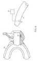
- FIG. 2is a front perspective view of the scanning assembly of FIG. 1 ;
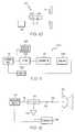
- FIG. 3is a diagrammatic view of an embodiment of a radiation source assembly of the scanning assembly of FIG. 1 ;
- FIG. 4is a front view taken along line 4 - 4 of FIG. 1 ;
- FIG. 5is a front view of a drive mechanism usable with the scanning assembly of FIG. 1 ;
- FIG. 6is a representation of a path of scanned radiation provided by the scanning assembly of FIG. 1 ;
- FIG. 7is a schematic representation of radiation reflected by a reflector at two different positions
- FIG. 8is a side cross section of the distal end of the scanning assembly of FIG. 1 , illustrating various reference marks;
- FIG. 9is an embodiment of a scanning assembly including a system for controlling operation of the scanning assembly
- FIG. 10is another embodiment of a scanning assembly including a system for controlling operation of the scanning assembly
- FIG. 11is an embodiment of a system for detecting a loss of scan condition of the reflector
- FIG. 12is another embodiment of a system for detecting a loss of scan condition of the reflector
- FIG. 13is another embodiment of a system for detecting a loss of scan condition of the reflector
- FIG. 14is an exemplary plot of various waveforms.
- FIG. 15is an embodiment of a method for detecting a loss of scan condition using the system of FIG. 13 .
- a scanning assemblygenerally designated 10 , includes a scanning unit 12 configured to direct radiation onto an area of interest 14 .
- the area of interest 14may be located on or inside the body of a human or animal patient, but could also be nearly any area which is desired to be scanned/visualized.
- the scanning unit 12(or other components or subcomponents) can then collect the radiation that is reflected, scattered, refracted or otherwise perturbed or affected (hereinafter referred to as radiation that is “returned from” the illuminated area 14 ) by the area 14 receiving radiation.
- the collected radiationcan then be analyzed and processed to generate an image of the illuminated area 14 .
- the scanning unit 12includes a housing 16 which receives a source fiber 18 therein.
- the housing 16is generally cylindrical (see FIG. 2 ) and sized to be gripped and manually manipulated, although the housing 16 can take any of a variety of forms, shapes and sizes.
- the source fiber 18is operatively coupled to a radiation source 20 to transmit radiation from the radiation source 20 to a position inside of the housing 16 or adjacent to a reflector 26 .
- the radiation source 20can take any of a variety of forms, including light emitting diodes (LEDs), lasers, thermal sources, arc sources, fluorescent sources, gas discharge sources, other sources, or combinations of these sources.
- the radiation provided by the radiation source 20can include energy in the visible light spectrum, such as red, green, or blue radiation, or various combinations thereof, although the radiation need not necessarily be within the visible spectrum.
- the source fiber 18may take the form of one or more optical fibers, or various other energy transmission means sufficient to transmit radiation from the radiation source 20 .
- FIG. 3is a block diagram of one implementation of the radiation source 20 .
- the radiation source 20includes multiple sources, each capable of generating radiation at a selected wavelength. Five sources are shown here, denoted A thru E.
- the outputs of the radiation sources A-Emay, in some embodiments, be brought together in combiner element 21 to yield an output beam 17 .
- Combiner 21may also include beam-shaping optics such as one or more collimating lenses and/or apertures.
- the sourcesmay be of various types such as, for instance, light emitting diodes (LEDs), lasers, thermal sources, arc sources, fluorescent sources, gas discharge sources, or others.
- Signals 23may be provided by controller 58 ( FIG. 1 ) to one or more of the sources and optionally the combiner 21 .
- Signals 23may optionally control wavelength, power, modulation or other beam properties.
- the wavelength of radiationmay be selected for imaging and/or therapy.
- An “imaging beam”refers to radiation selected for use in creating an image of a surface or region and a “therapeutic beam” refers to radiation selected to provide treatment of a condition such as diseased or damaged tissue.
- sources A, B and Cemit red, green and blue radiation;
- source Demits an aiming beam at a wavelength selected to yield a distinct contrast to the typical target material;
- source Eemits a therapeutic beam at a wavelength that is highly absorbed and moreover can be efficiently generated at high power to treat diseased or damaged tissue.
- the aiming beammay be provided by source separate from the therapeutic beam source E.
- an aiming beammay be provided by source E as a reduced power therapeutic beam. Details of delivering therapeutic and imaging beams using a scanning assembly are described in greater detail in pending U.S. patent application Ser. No. 11/716,806, filed Mar. 12, 2007, entitled MEDICAL DEVICE INCLUDING SCANNED BEAM UNIT FOR IMAGING AND THERAPY, the details of which are hereby incorporated by reference as if fully set forth herein.
- the end of the source fiber 18may be shaped or polished to create a beam 22 of known divergence. After exiting the source fiber 18 the beam 22 may pass through, and be shaped by a lens or other optics 24 to create a desired beam shape. In other embodiments, the beam 22 may not pass through and be shaped by a lens or other optic to create the desired beam shape.
- the scanning unit 12includes the mirror or reflector 26 at or adjacent to its distal end.
- the reflector 26may take the form of a micromirror or other reflective surface.
- the reflector 26thus may take the form of or include a microelectrical mechanical system (“MEMS”) manufactured using standard MEMS techniques.
- the reflector 26may include a semiconductor substrate, such as silicon, with a reflective outer surface, such as gold or other suitable material, forming its outer reflective surface 28 . However the surface 28 may take various other forms, such as a multilayer dielectric coating.
- the reflector 26includes a central aperture 30 that is positioned to allow the beam 22 to pass therethrough.
- the reflector 26 and scanning unit 12can take any of a variety of shapes and configurations besides that shown herein.
- the beam 22may be laterally offset from the reflector 26 , and guided to the reflector 26 by another mirror/reflector.
- the beam 22After passing through the aperture 30 of the reflector 26 , the beam 22 approaches an optical element 32 that is positioned at a distal end of the scanning unit 12 .
- the optical element 32can be generally hemispherical and is typically referred to as a dome. However, the shape, curvature, contour, and surface treatment of the optical element 32 may vary depending on the desired application/use of the scanning unit 12 and the desired optical properties of the optical element 32 .
- the optical element 32may form a hermetic seal with the housing 16 to protect the internal elements of the scanning unit 12 from the surrounding environment.
- the optical element 32may include a reflecting surface 34 on its inner surface.
- the reflecting surface 34may be directly deposited on the inner surface of the optical element 32 , or integrated into the optical element 32 , or can take the form of a separate and discrete element coupled to the optical element 32 .
- the beam 22After the beam 22 passes through the aperture 30 of the reflector 26 , the beam 22 impinges upon the reflecting surface 34 which reflects the beam 22 and re-directs the beam 22 toward the reflector 26 .
- the inner surface of the optical element 32 and/or the reflecting surface 34may also shape the beam 22 as desired due to the shape or curvature of the reflecting surface 34 . If the beam 22 is laterally offset from the center of the scanning unit 12 in the arrangement briefly described above, the reflecting surface 34 on the optical element 32 may be omitted.
- the reflector 26may be independently oscillatable/movable about two orthogonal axes, such as axes 38 , 40 shown in FIGS. 4 and 5 .
- the reflector 26may be coupled to an inner support structure 42 , that generally surrounds the reflector 26 , by a pair of opposed, generally aligned torsion arms 44 .
- the inner support structure 42is coupled to an outer support structure 46 , that generally surrounds the inner support structure 42 , by a pair of opposed, generally aligned torsion arms 48 .
- the outer torsion arms 48are generally perpendicular to the inner torsion arms 44 .
- the reflector 26may double gimbaled or otherwise pivotable about the two axes 38 , 40 to position the reflector 26 as desired.
- the inner support structure 42may have a pair of opposed comb structures 50 that are interleaved with comb structures 52 of the reflector 26 .
- the outer support structure 46may have a pair of opposed comb structures 54 that are interleaved with comb structures 56 of the inner support structure 42 .
- a voltagecan be applied to one or both comb structures 50 , 52 which causes the reflector 26 to pivot about arms 44 /axis 40 .
- a voltagecan be applied to one or both comb structures 54 , 56 to cause the reflector 26 to pivot about arms 48 /axis 38 .
- the voltagescan be applied by a controller 58 to thereby control movement and position of the reflector 26 .
- FIG. 5illustrates a reflector 26 that is movable/oscillatable through the application of electrical forces by comb drives.
- electrical/electrostatic forcescan be applied in a variety of manners besides comb drives.
- various other forcesmay be utilized to drive the movement/oscillation of the reflector 26 , such as magnetic, piezoelectric, or combinations of these drivers.
- the range of motion of the reflector 26can be selected as desired, but in one embodiment the reflector 26 is pivotable about the axis 38 at least about 60 degrees, and the reflector 26 is pivotable about the axis 40 at least about 60 degrees, or in another case at least about 40 degrees (with all angles being full angle values representing the full range of motion of the reflector 26 ).
- the reflector 26may guide the beam 22 to define a field of view or field of scan, which is the angular extent of the area illuminated by the scanned beam. It should be noted that the displayed image may be less than the field of view.
- the reflector 26is moved such that the reflector 26 has a significantly higher frequency about one axis than about the other axis.
- the reflector 26is moved such that it has a frequency about the axis 40 that is at least about fifteen times greater, up to about 600 times or even greater, than the frequency of oscillation about the axis 38 .
- the reflector 26may have a frequency of about 19 kHz about the axis 40 , and about 60 Hz about the axis 38 .
- the reflector 26may be moved about each axis 38 , 40 in a reciprocating motion having a velocity profile that is generally sinusoidal to provide a bi-sinusoidal scan pattern.
- the velocity profileneed not necessarily be at or close to sinusoidal.
- the reflector 26may be oscillated at or close to resonant frequency about each axis 38 , 40 (i.e. in a dual resonant manner).
- the frequency of oscillationscan be at nearly any desired value to allow the reflected beam 22 to scan across the illuminated area 14 in the desired manner (such as in a progressive scan pattern). For example, FIG.
- the scan patternneed not necessarily be implemented by a progressive scan pattern. Instead, the scan pattern can take any of a variety of other shapes or forms, including a spiral pattern scanned by a flexible or movable optical fiber, or nutating mirror assembly, or other mechanism such as a vibrating optical fiber.
- the scanning unit 10includes a collector 64 , which collects/senses radiation emitted by the scanning unit 12 that is returned from the illuminated area 14 .
- the collector 64is configured coaxially within the housing 16 (see also FIG. 2 ).
- the collector 64may take a variety of shapes and forms, and also need not necessarily be physically coupled to the housing 16 . Since the image of the illuminated area 14 is constructed from the point of view of the “illuminator” (i.e. the reflector 26 ), the position at which the radiation is collected does not affect the geometry of the image.
- the shapes of the images or structures in the illuminated area 14may become more or less visible, or even change from visible to not visible, but the geometry of the shapes, and their spatial relationship, remains unchanged.
- movement of the collector 64may affect the quality of the image.
- the collector 64should be located sufficient close to the illuminated area 14 to effectively detect perturbed radiation.
- the collector 64may take any of a variety of forms, and in one embodiment includes a plurality of small diameter, multimode collecting fibers.
- the ends of the fibersmay be polished and arranged in a generally planar manner (or otherwise) to define an aperture.
- the reflector 26 /scanning unit 12directs radiation 22 at the area 14 , returned radiation impinges on the aperture, and the collecting fibers then conduct the received radiation to a radiation detector assembly 64 .
- the radiation detector assembly 66 /controller 58may be operatively coupled to an image processor 67 , which is in turn coupled to a display device 68 (such as a display screen, television screen, monitor, etc.) that can display a visual representation (a video image) of the illuminated area 14 based upon data provided by the collector 64 .
- a display device 68such as a display screen, television screen, monitor, etc.
- FIG. 7schematically illustrates the operation of the reflector 26 in conjunction with the collector 64 .
- the reflector 26receives a beam of radiation 22 from the source fiber 18 and uses its reflective surface 28 to direct the beam 22 onto a surface or illuminated area 14 .
- the beam 22 deflected by the reflector 26is in a position shown as 70 , and impinges upon the surface to illuminate point 72 .
- the reflector 26moves or oscillates about axis 40 (indicated by arrow A) at a later point in time the beam is in the position shown as 74 where the beam illuminates point 76 .
- the directed radiationis reflected, absorbed, scattered, refracted or otherwise affected by the filed of view 14 , at least some of which is detected by the collector 64 .
- the perturbed radiationmay leave the area 14 in many directions and thus the collector 64 may only capture that fraction of reflected radiation which reaches its aperture.
- the radiation detector assembly 66may take the form of or include a bolometer, photodiode or avalanche photodiode that can output a series of electrical signals corresponding to power, amplitude, or other characteristic of each wavelength of radiation detected.
- the radiation detector assembly 66may include, or be coupled to, an analog-to-digital converter to convert the image data into a digital image signal stream.
- the signalscan be used/processed by the image processor 67 (which could be, in one embodiment, part of the controller 58 ) to generate an image of the illuminated area 14 which can be displayed on a display device 68 , or printed, stored, or further processed.
- the imagecan be generated by taking into consideration, for example, the position, angle, intensity and wavelength of beam 22 directed by the reflector 26 , and the amount and/or wavelength of radiation sensed by the collector 50 .
- the housing 16may constitute or include an elongate shaft (which can be either rigid or flexible) that is insertable into the body of a patient.
- the radiation source 20 , controller 58 , radiation detector assembly 66 , image processor 67 and display deviceare 68 typically not insertable into the patient or carried in the housing 16 , but are instead typically components positioned outside the body and accessible for use and viewing.
- a reference mark 80 or markerpositioned to reflect the beam of radiation after the beam reflects off of the reflector 26 , but before the beam impinges upon the area of interest 14 .
- a referencealso known as an auto correction marking (“ACM”)
- ACMauto correction marking
- the reference mark 80can have any variety of indicia, designs, patterns or the like (collectively termed “indicia” herein) printed, positioned, or otherwise formed or located thereon.
- FIG. 9illustrates some examples of indicia that may be carried by the reference mark 80 .
- the indiciamay be composed of high contrast patterns, geometric shapes or other forms of a type not expected to be found in the area of interest 14 to allow easy identification of the reference mark 80 .
- the indicia of the reference mark 80may include portions that are generally opaque to the radiation.
- the reference mark 80can aid in tracking the position of the reflector 26 , and thereby providing accurate reconstruction of the scanned image.
- Various details of use of a reference mark 80are described in pending U.S. patent application Ser. No. 11/845,457, filed Aug. 27, 2007, entitled POSITION TRACKING AND CONTROL FOR A SCANNING ASSEMBLY, the details of which are hereby incorporated by reference as if fully set forth herein.
- the reference mark 80is positioned on the inner surface of the optical element.
- the reference mark 80is shown in FIG. 8 illustrates another position wherein the reference mark 80 is formed in, or embedded in, or laminated on, the optical element.
- the reference mark 80can also be positioned on an outer surface of the optical element, or at other positions between the reflector and the area of interest 14 .
- the reference mark 80may thus be positioned such that the radiation beam impinges upon the reference mark 80 before the beam entirely passes through the optical element.
- MPEis the maximum power or energy density (in J/cm 2 or W/cm 2 ) exposure to a light source determined by one or more of these organizations.
- IECInternational Electrotechnical Commission
- ANSIAmerican National Standards Institute
- MPEis the maximum power or energy density (in J/cm 2 or W/cm 2 ) exposure to a light source determined by one or more of these organizations.
- the scanning unit 12is not located within the desired body cavity, it may be desirable to prevent unintended output of certain power levels until the scanning unit is within the desired body cavity.
- the reflector 26is not scanning properly, it may be desirable to detect this condition to prevent output of unintended doses of radiation.
- the scanning assembly 10may include a system, generally referred to as element 71 , that automatically limits a power level of the radiation source 20 when the scanning unit 12 is outside the intended cavity.
- the system 71includes a magnetically actuated switch 73 that is used to control operation of the radiation source 20 .
- the magnetically actuated switch 73is responsive to a magnetic field, which is used to toggle the switch between states. For example, a first state of the magnetically actuated switch 73 may indicate that high power is available and another state may indicate that high power is not available.
- the magnetically actuated switch 73can be used to limit output power of the scanning assembly 10 when the magnetically actuated switch is in its first state.
- the magnetic fieldmay be provided by a magnet 75 that is associated with an instrument to facilitate insertion of the scanning unit 12 into the body.
- the magnet 75may be carried by a stabilizer 79 for stabilizing the scanning unit 12 when inserted into a natural orifice, such as the mouth of a patient.
- the magnet 75may be carried by a trocar, such as that commercially available from Johnson & Johnson Gateway, LLC for artificial ports. As the shaft of the scanning assembly 10 is passed from its distal end to a proximal location through the opening, an insertion is registered due to the magnetic field provided by the magnet 75 , for example, by a controller and high power is enabled.
- an external accessory 77is provided to reset the magnetically actuated switch 73 to the state that disables high power operation, for example, that can be operated using input from an operator.
- the accessory 77allows the operator to place the magnetically actuated switch 73 in the state that enables high power operation.
- FIG. 10shows another embodiment 85 where multiple sensors 81 A and 81 B, such as Hall sensors, are provided to distinguish between whether the scanning unit 12 is being inserted or retracted.
- the sensors 81 A and 81 Bprovide a signal in response to a magnetic field and are connected to a controller/processor 58 that includes logic for distinguishing between an insertion or retraction.
- sensor 81 Ais located distally of sensor 81 B on the housing 16 such that if controller/processor 58 ( FIG. 1 ) receives a signal from sensor 81 A, then 81 B, an insertion is identified and high power is enabled. Conversely, if the controller/processor 58 receives a signal from sensor 81 B, then 81 A, a retraction is identified and high power is disabled.
- the magnetically actuated switch/sensorscan have a limited range of detection of the magnet.
- the switch/sensorsmay be capable of detecting the magnet over a range of about 1 ⁇ 8 to 1 inch, such as about 1 ⁇ 4 inch.
- the state of the switchmay be stored, for example, in memory or in another component such as a latch.
- magnetically actuated sensorsare described above, other sensor types may be used, such as impedance sensors, capacitive sensors, etc. Additionally, mechanical approaches may be utilized such as a ratcheting system in combination with a magnetic switch, where the ratcheting system temporarily locks the magnetic switch in a particular state as the switch is passed by the magnetic field.
- a magnetically latching devicemay assume the first state upon passing the magnet 75 in one direction (e.g., an insertion) and assume the second state when passing the magnet in another direction (e.g., a retraction).
- multiple magnetically actuated devicesmay be employed for backup and robustness.
- the system 71 , 85may be calibrated, such that when the scanning assembly 10 is turned on, it is assumed the scanning unit 12 is outside the intended cavity and high power is not enabled by default.
- a user overridemay be provided and used to enable high power manually.
- the above descriptionrelates to determining if the scanning unit 12 is located within the desired cavity or enclosure, it may be desirable to determine whether or not the reflector 26 is scanning properly.
- a loss of scan condition of the reflector 26can result in unintended radiation doses being delivered to tissue.
- Various systemsmay be utilized to detect a loss of motion condition of the reflector 26 .
- some systemsmay use the reference mark, however, other systems may not.
- the reference mark 80may be used because the image processor 67 continuously monitors the received data stream for the characteristic signature of the reference mark 80 , a persistent lack of such signature can imply that the reflector 26 is no longer moving as intended (i.e., a loss of scan condition is present). In such event, the radiation source 20 can be commanded to terminate emissions of the radiation beam.
- a system 100 for detecting a loss of scan conditionutilizes the signal produced by the radiation detector assembly 66 to detect the loss of scan condition.
- the signalsinclude spectral components at harmonics of the scan frequencies.
- the system 100utilizes the expected periodic structure of the signals to determine whether the reflector 26 is scanning. If the scanning of the reflector 26 stops, then the spectrum of the output collapses, i.e., the value of the signal becomes a constant, for example, zero or some other constant.
- the system 100looks for lines in the spectrum not at the constant. If those lines disappear, then it may be the case that the reflector 26 has stopped scanning. Other possibilities are that the receive system is not operating properly or that there is no beam being generated. In some embodiments, the system 100 can distinguish between these possibilities. For example, the system 100 may also monitor the radiation source 20 and/or monitor the beam of radiation output by the radiation source before it passes to the reflector 26 to identify whether no beam is being generated.
- the system 100includes a filter 102 that is used to filter the signals from the radiation detector assembly 66 , for example, prior to subjecting the signals to any nonlinear processing.
- the filter 102is a bandpass filter that passes frequencies within a certain range and rejects frequencies outside that range.
- a low end of the rangemay be set above frequencies resulting from manual movement of the scanning unit 12 with the reflector 26 stationary (i.e., above frequencies one might expect from a user swinging the scanning unit 12 should the reflector 26 stop scanning).
- the upper end of the rangemay be set at least high enough pass frequencies associated with the system's highest resolution, which may be governed by the diameter of the beam and the electrical bandwidth of the detectors and amplifiers.
- the filter 102may be a comb filter that adds a delayed version of the signal to itself, causing constructive and destructive interference thereby providing a periodic response in frequency.
- the comb filtercan have a large number of passbands that are centered on frequencies at which the spectrum has energy.
- a bandpass filter(or separate low and high-stop filters) may also be included to filter out extreme low and high frequencies.
- the filter 102may be a low-pass filter that allows only those low frequencies to pass that would be expected should the reflector 26 stop scanning.
- the reference mark 80may be utilized for providing the spectral components.
- the filter 102may be a matched filter that responds maximally to the signal corresponding to the structure of the reference mark 80 .
- the system 100includes a comparator 104 that compares the magnitudes of the output of the filter 102 against a limit.
- the limitmay vary with operating conditions, scene, etc.
- a qualifier 106determines whether the reflector 26 has stopped scanning. In some embodiments, the qualifier 106 ignores brief low outputs, which may occur for reasons other than loss of scanning. If the qualifier 106 determines there is a loss of scan condition, then a laser disable input 108 (e.g., incorporated in the controller 58 , source 20 or separate component) shuts down the radiation source. In some embodiments, the laser disable input 108 may operate a beam blocker, such as part of an external treatment system.
- the processor 58may include the comparator 104 and qualifier 106 .
- FIG. 12shows an alternative embodiment in which radiation reflected and returning through the source fiber 18 is used to detect a loss of scan condition.
- a fiber optic coupler 110is used to separate the return 118 beam from the source fiber 18 and direct the return beam to a detector 112 .
- the detector 112provides an output to the processor 58 , which monitors the output to determine whether the reflector 26 is scanning and interrupts the outgoing beam should the determination be made that scanning has stopped.
- the processor 58looks for temporal signal variations in the output of the detector 112 .
- the reflector 26is oscillating, the change in scene reflectance as the scanned beam is reflected by varying tissue, structures and surface angle causes a variation of radiation reflected back into the source fiber 18 in a somewhat unpredictable way, however, the temporal frequency content will be different if the scanner is scanning versus stopped.
- the frequency contentcan be analyzed to determine if the reflector is likely to be scanning. The absence of such temporal signal variations can be interpreted as an indication of a loss of scan condition and the radiation source 20 can be shut down in response.
- the reference mark 80could be applied to the dome surface at a position that is outside the area of interest and outside the acceptance angle of the collector, but at a position that can be interrogated by the outgoing beam 116 .
- the reference mark 80can provide a repeatable reflection signature as the mirror oscillates, which is recognized by the processor 58 . The absence of this repeatable reflection signature can be interpreted as an indication of a loss of scan condition and the radiation source 20 can be shut down in response.
- the reflector 26can be moved employing comb drives.
- the comb drivescan be operated at or near the mechanical resonant frequency to achieve minimum operating currents (i.e., at or near the maximum system impedance).
- impedance at the operating frequencyis constant or slowly varying (as a function of temperature). This slowly varying change in impedance can be used to alter the drive frequency as the resonant frequency shifts.
- disruption of operation of the comb drive 124will result in a change in the mean value of the impedance. Once this mean value of the impedance changes, this changed steady-state value can indicate a loss of scan condition. In some instances, disruption of operation of the comb drive will change the periodic variation of impedance (e.g., it will become non-periodic) or will take a different value that can be detected, which can indicate a loss of scan condition.
- FIG. 13shows a block diagram of a system 120 to detect a loss of scan condition using comb drive impedance measurements.
- the system 120includes comb drive electronics 122 , which contains all the electrical components required to generate the desired signal to cause activation of the comb drive 124 , such as power supplies, amplifiers, active analog feedback circuits, waveform generators, digital control functions, etc.
- the comb drive electronics 122causes creation of a voltage waveform similar to that shown by FIG. 14 , which is only one example from a large number of waveforms that could be generated.
- the electrostatic comb drive 124the voltage is applied only at a time when the reflector 26 is off-center and in synchrony with the angular displacement of the reflector and turned off just prior to crossing the center, or zero position.
- the impedance of the comb drive 124is dominated by the capacitance between the stationary and moveable portions of the comb drive.
- capacitancecan be computed by
- the projected area between the fingersis a function of rotational angle between the stationary and moving portions of the comb drive and can be approximated, to the first order, as a cosine function with zero radians being defined as the angle between the stationary and moving portions when they are coplanar.
- the impedanceis at its maximum value (minimum capacitance) when the reflector 26 is at its largest deflection angle and at its smallest when the reflector is centered (zero degrees).
- an impedance meter 126measures the instantaneous impedance of the drive combs it is connected to.
- a series of time varying impedancessimilar to those shown by FIG. 14 where trace 128 occurs at the period of the oscillatory period of the reflector 26 .
- trace 128occurs at the period of the oscillatory period of the reflector 26 .
- the output of the impedance meter 126is a signal (analog or digital) corresponding to the impedance of the comb drive.
- An impedance monitoring element 130accepts the output from the impedance meter 126 and determines if the comb drive is operating normally or it there is a loss of scan condition.
- the impedance metercan make rapid measurements of the impedance (e.g., many measurements per cycle of the reflector's movement in either axis) and provide an output to the impedance monitoring component 130 indicative of these measurements.
- the impedance monitoring element 130may include low and high pass filters.
- the low pass filteris constructed to provide an affirmative output if the rate of change of the instantaneous impedance measurements are small, likely indicating a loss of scan condition.
- the high pass filtermay be constructed to provide an affirmative output if the rate of change of the instantaneous impedance measurements are large, likely indicating normal operation.
- Such filtersmay be implemented in analog (continuous time) or digital (discrete time) form.
- Finite Impulse Response (FIR) filters of Infinite Impulse Response (IIR) filterscould be used.
- FIRFinite Impulse Response
- IIRInfinite Impulse Response
- a conversion of the data stream to the frequency domain using a Fourier Transform (DCTs of FFTs) and then looking for threshold values in appropriate frequency binscould be used.
- FIG. 15One digital implementation of the impedance metering and monitoring functions of FIG. 13 is illustrated in FIG. 15 .
- the voltage applied to the comb driveis converted to a digital value at a rate of at least two times the highest frequency component of interest in the drive waveform at step 140 .
- the drive currentis converted to a digital value at the rate specified in step 140 .
- Steps 140 and 142may occur at the same time, although they are shown separately.
- the instantaneous impedanceis calculated at each of the sample points at step 144 .
- the output of the high and low pass filtersis calculated in step 146 .
- the filter outputsare further qualified (for example, a transient condition caused by noise should be rejected, and nonmeaningful combinations of filter outputs ignored) and output.
- the qualified output signalsare presented for use in the system, for example to present status or alarm information to the user, and to shut down the source or block the output beam in the event of a fault.
- the A/D converters, clock generators, computational and logic elements involved in these stepsare all part of a single integrated circuit.
Landscapes
- Physics & Mathematics (AREA)
- Health & Medical Sciences (AREA)
- Life Sciences & Earth Sciences (AREA)
- Optics & Photonics (AREA)
- Surgery (AREA)
- General Physics & Mathematics (AREA)
- Engineering & Computer Science (AREA)
- Biomedical Technology (AREA)
- Animal Behavior & Ethology (AREA)
- Pathology (AREA)
- Nuclear Medicine, Radiotherapy & Molecular Imaging (AREA)
- Heart & Thoracic Surgery (AREA)
- Medical Informatics (AREA)
- Molecular Biology (AREA)
- Radiology & Medical Imaging (AREA)
- General Health & Medical Sciences (AREA)
- Public Health (AREA)
- Veterinary Medicine (AREA)
- Astronomy & Astrophysics (AREA)
- Biophysics (AREA)
- Multimedia (AREA)
- Laser Surgery Devices (AREA)
- Endoscopes (AREA)
Abstract
Description
where ∈ is the dielectric constant of the material between the comb fingers, A is a measure of the area of the fingers and d is the distance between the comb fingers. For practical systems, the projected area between the fingers is a function of rotational angle between the stationary and moving portions of the comb drive and can be approximated, to the first order, as a cosine function with zero radians being defined as the angle between the stationary and moving portions when they are coplanar. The impedance is at its maximum value (minimum capacitance) when the
Claims (21)
Priority Applications (2)
| Application Number | Priority Date | Filing Date | Title |
|---|---|---|---|
| US11/846,039US7925333B2 (en) | 2007-08-28 | 2007-08-28 | Medical device including scanned beam unit with operational control features |
| PCT/US2008/074275WO2009032610A2 (en) | 2007-08-28 | 2008-08-26 | Medical device including scanned beam unit with operational control features |
Applications Claiming Priority (1)
| Application Number | Priority Date | Filing Date | Title |
|---|---|---|---|
| US11/846,039US7925333B2 (en) | 2007-08-28 | 2007-08-28 | Medical device including scanned beam unit with operational control features |
Publications (2)
| Publication Number | Publication Date |
|---|---|
| US20090062659A1 US20090062659A1 (en) | 2009-03-05 |
| US7925333B2true US7925333B2 (en) | 2011-04-12 |
Family
ID=40111053
Family Applications (1)
| Application Number | Title | Priority Date | Filing Date |
|---|---|---|---|
| US11/846,039Expired - Fee RelatedUS7925333B2 (en) | 2007-08-28 | 2007-08-28 | Medical device including scanned beam unit with operational control features |
Country Status (2)
| Country | Link |
|---|---|
| US (1) | US7925333B2 (en) |
| WO (1) | WO2009032610A2 (en) |
Cited By (7)
| Publication number | Priority date | Publication date | Assignee | Title |
|---|---|---|---|---|
| US20120048191A1 (en)* | 2010-08-24 | 2012-03-01 | Homag Holzbearbeitungssysteme Ag | Transmission Device for Radiation |
| US8715173B2 (en)* | 2012-03-12 | 2014-05-06 | United Sciences, Llc | Otoscanner with fan and ring laser |
| US8900126B2 (en) | 2011-03-23 | 2014-12-02 | United Sciences, Llc | Optical scanning device |
| US9042967B2 (en) | 2008-05-20 | 2015-05-26 | University Health Network | Device and method for wound imaging and monitoring |
| JP2015132768A (en)* | 2014-01-15 | 2015-07-23 | 株式会社リコー | Optical deflection device and image display device |
| US9860426B2 (en)* | 2014-01-24 | 2018-01-02 | E-Imagedata Corp. | Multi-mode image capture systems and methods |
| US10438356B2 (en) | 2014-07-24 | 2019-10-08 | University Health Network | Collection and analysis of data for diagnostic purposes |
Families Citing this family (3)
| Publication number | Priority date | Publication date | Assignee | Title |
|---|---|---|---|---|
| JP5974208B1 (en)* | 2014-11-10 | 2016-08-23 | オリンパス株式会社 | Optical scanning observation system |
| WO2017163361A1 (en)* | 2016-03-24 | 2017-09-28 | オリンパス株式会社 | Optical scanning device and scanning type endoscope |
| EP4490559A2 (en)* | 2022-03-09 | 2025-01-15 | Banner Engineering Corp. | Opto-electronic emergency stop device |
Citations (317)
| Publication number | Priority date | Publication date | Assignee | Title |
|---|---|---|---|---|
| US3758199A (en) | 1971-11-22 | 1973-09-11 | Sperry Rand Corp | Piezoelectrically actuated light deflector |
| US3959582A (en) | 1975-03-31 | 1976-05-25 | The United States Of America As Represented By The Secretary Of The Navy | Solid state electronically rotatable raster scan for television cameras |
| US4082635A (en) | 1976-08-02 | 1978-04-04 | Ciba-Geigy Corporation | Ultraviolet light-curable diacrylate hydantoin adhesive compositions |
| US4141362A (en) | 1977-05-23 | 1979-02-27 | Richard Wolf Gmbh | Laser endoscope |
| US4313431A (en) | 1978-12-06 | 1982-02-02 | Messerschmitt-Boelkow-Blohm Gesellschaft Mit Beschraenkter Haftung | Endoscopic apparatus with a laser light conductor |
| US4379039A (en) | 1979-12-29 | 1983-04-05 | Toyo Boseki Kabushiki Kaish | Ultraviolet curable resin composition |
| US4403273A (en) | 1981-01-26 | 1983-09-06 | Olympus Optical Co., Ltd. | Illuminating system for endoscopes |
| US4409477A (en) | 1981-06-22 | 1983-10-11 | Sanders Associates, Inc. | Scanning optical system |
| US4421382A (en) | 1980-04-01 | 1983-12-20 | Asahi Kogaku Kogyo Kabushiki Kaisha | Fiber retaining device for power laser |
| US4524761A (en) | 1981-03-16 | 1985-06-25 | Olympus Optical Co., Ltd. | Endoscope apparatus |
| US4527552A (en) | 1981-03-25 | 1985-07-09 | Olympus Optical Co., Ltd. | Endoscope apparatus |
| US4573465A (en) | 1981-11-19 | 1986-03-04 | Nippon Infrared Industries Co., Ltd. | Laser irradiation apparatus |
| US4576999A (en) | 1982-05-06 | 1986-03-18 | General Electric Company | Ultraviolet radiation-curable silicone release compositions with epoxy and/or acrylic functionality |
| US4597380A (en) | 1982-09-30 | 1986-07-01 | Laser Industries Ltd. | Endoscopic attachment to a surgical laser |
| US4643967A (en) | 1983-07-07 | 1987-02-17 | Bryant Bernard J | Antibody method for lowering risk of susceptibility to HLA-associated diseases in future human generations |
| US4676231A (en) | 1984-09-14 | 1987-06-30 | Olympus Optical Co., Ltd. | Laser probe |
| US4760840A (en) | 1986-12-16 | 1988-08-02 | The Regents Of The University Of California | Endoscopic laser instrument |
| US4803550A (en) | 1987-04-17 | 1989-02-07 | Olympus Optical Co., Ltd. | Imaging apparatus having illumination means |
| US4872458A (en) | 1986-09-16 | 1989-10-10 | Olympus Optical Co., Ltd. | Thermotherapy apparatus |
| US4902083A (en) | 1988-05-31 | 1990-02-20 | Reflection Technology, Inc. | Low vibration resonant scanning unit for miniature optical display apparatus |
| US4902115A (en) | 1986-09-22 | 1990-02-20 | Olympus Optical Co., Ltd. | Optical system for endoscopes |
| DE3837248A1 (en) | 1988-10-28 | 1990-05-03 | Teichmann Heinrich Otto Dr Phy | Device for treating skin lesions |
| US4934773A (en) | 1987-07-27 | 1990-06-19 | Reflection Technology, Inc. | Miniature video display system |
| US4938205A (en) | 1988-05-27 | 1990-07-03 | The University Of Connecticut | Endoscope with traced raster and elemental photodetectors |
| US5003300A (en) | 1987-07-27 | 1991-03-26 | Reflection Technology, Inc. | Head mounted display for miniature video display system |
| US5023905A (en) | 1988-07-25 | 1991-06-11 | Reflection Technology, Inc. | Pocket data receiver with full page visual display |
| US5048077A (en) | 1988-07-25 | 1991-09-10 | Reflection Technology, Inc. | Telephone handset with full-page visual display |
| US5074860A (en) | 1989-06-09 | 1991-12-24 | Heraeus Lasersonics, Inc. | Apparatus for directing 10.6 micron laser radiation to a tissue site |
| US5078150A (en) | 1988-05-02 | 1992-01-07 | Olympus Optical Co., Ltd. | Spectral diagnosing apparatus with endoscope |
| US5163945A (en) | 1991-10-18 | 1992-11-17 | Ethicon, Inc. | Surgical clip applier |
| US5163936A (en) | 1991-01-22 | 1992-11-17 | Reliant Laser Corp. | Endoscopic mirror laser beam delivery system and method for controlling alignment |
| US5172685A (en) | 1988-05-27 | 1992-12-22 | The University Of Connecticut | Endoscope and video laser camera system therefor |
| US5192288A (en) | 1992-05-26 | 1993-03-09 | Origin Medsystems, Inc. | Surgical clip applier |
| US5200838A (en) | 1988-05-27 | 1993-04-06 | The University Of Connecticut | Lateral effect imaging system |
| US5200819A (en) | 1988-05-27 | 1993-04-06 | The University Of Connecticut | Multi-dimensional imaging system for endoscope |
| US5207670A (en) | 1990-06-15 | 1993-05-04 | Rare Earth Medical, Inc. | Photoreactive suturing of biological materials |
| US5218195A (en) | 1991-06-25 | 1993-06-08 | Fuji Photo Film Co., Ltd. | Scanning microscope, scanning width detecting device, and magnification indicating apparatus |
| US5251025A (en) | 1987-03-05 | 1993-10-05 | Fuji Optical Systems, Inc. | Electronic video dental camera |
| US5251613A (en) | 1991-05-06 | 1993-10-12 | Adair Edwin Lloyd | Method of cervical videoscope with detachable camera |
| US5269289A (en) | 1990-12-25 | 1993-12-14 | Olympus Optical Co., Ltd. | Cavity insert device using fuzzy theory |
| US5318024A (en) | 1985-03-22 | 1994-06-07 | Massachusetts Institute Of Technology | Laser endoscope for spectroscopic imaging |
| US5334991A (en) | 1992-05-15 | 1994-08-02 | Reflection Technology | Dual image head-mounted display |
| US5368015A (en) | 1991-03-18 | 1994-11-29 | Wilk; Peter J. | Automated surgical system and apparatus |
| US5370643A (en) | 1992-07-06 | 1994-12-06 | Ceramoptec, Inc. | Multiple effect laser delivery device and system for medical procedures |
| US5387197A (en) | 1993-02-25 | 1995-02-07 | Ethicon, Inc. | Trocar safety shield locking mechanism |
| US5393647A (en) | 1993-07-16 | 1995-02-28 | Armand P. Neukermans | Method of making superhard tips for micro-probe microscopy and field emission |
| US5436655A (en) | 1991-08-09 | 1995-07-25 | Olympus Optical Co., Ltd. | Endoscope apparatus for three dimensional measurement for scanning spot light to execute three dimensional measurement |
| US5467104A (en) | 1992-10-22 | 1995-11-14 | Board Of Regents Of The University Of Washington | Virtual retinal display |
| US5488862A (en) | 1993-10-18 | 1996-02-06 | Armand P. Neukermans | Monolithic silicon rate-gyro with integrated sensors |
| US5531740A (en) | 1994-09-06 | 1996-07-02 | Rapistan Demag Corporation | Automatic color-activated scanning treatment of dermatological conditions by laser |
| US5545211A (en) | 1993-09-27 | 1996-08-13 | Sooho Medi-Tech Co., Ltd. | Stent for expanding a lumen |
| US5552452A (en) | 1993-03-15 | 1996-09-03 | Arch Development Corp. | Organic tissue glue for closure of wounds |
| US5557444A (en) | 1994-10-26 | 1996-09-17 | University Of Washington | Miniature optical scanner for a two axis scanning system |
| US5590660A (en) | 1994-03-28 | 1997-01-07 | Xillix Technologies Corp. | Apparatus and method for imaging diseased tissue using integrated autofluorescence |
| US5596339A (en) | 1992-10-22 | 1997-01-21 | University Of Washington | Virtual retinal display with fiber optic point source |
| US5608451A (en) | 1994-03-11 | 1997-03-04 | Olympus Optical Co., Ltd. | Endoscope apparatus |
| US5629790A (en) | 1993-10-18 | 1997-05-13 | Neukermans; Armand P. | Micromachined torsional scanner |
| US5649952A (en) | 1993-12-28 | 1997-07-22 | Advanced Cardiovascular Systems, Inc. | Expandable stents and method for making same |
| US5657165A (en) | 1995-10-11 | 1997-08-12 | Reflection Technology, Inc. | Apparatus and method for generating full-color images using two light sources |
| US5694237A (en) | 1996-09-25 | 1997-12-02 | University Of Washington | Position detection of mechanical resonant scanner mirror |
| US5701132A (en) | 1996-03-29 | 1997-12-23 | University Of Washington | Virtual retinal display with expanded exit pupil |
| US5713891A (en) | 1995-06-02 | 1998-02-03 | Children's Medical Center Corporation | Modified solder for delivery of bioactive substances and methods of use thereof |
| US5728121A (en) | 1996-04-17 | 1998-03-17 | Teleflex Medical, Inc. | Surgical grasper devices |
| US5735792A (en) | 1992-11-25 | 1998-04-07 | Clarus Medical Systems, Inc. | Surgical instrument including viewing optics and an atraumatic probe |
| US5742421A (en) | 1996-03-01 | 1998-04-21 | Reflection Technology, Inc. | Split lens video display system |
| US5742419A (en) | 1995-11-07 | 1998-04-21 | The Board Of Trustees Of The Leland Stanford Junior Universtiy | Miniature scanning confocal microscope |
| US5768461A (en) | 1995-11-02 | 1998-06-16 | General Scanning, Inc. | Scanned remote imaging method and system and method of determining optimum design characteristics of a filter for use therein |
| US5797944A (en) | 1992-11-12 | 1998-08-25 | Ethicon Endo-Surgery, Inc. | Visualization trocar |
| US5817061A (en) | 1997-05-16 | 1998-10-06 | Ethicon Endo-Surgery, Inc. | Trocar assembly |
| US5823943A (en) | 1994-08-02 | 1998-10-20 | Olympus Optical Co., Ltd | Light source device for endoscopes |
| US5827176A (en) | 1996-02-13 | 1998-10-27 | Fuji Photo Optical Co., Ltd. | Endoscopic imaging system with rotating photoelectric line sensor |
| US5841553A (en) | 1995-12-26 | 1998-11-24 | Xros, Inc. | Compact document scanner or printer engine |
| US5861549A (en) | 1996-12-10 | 1999-01-19 | Xros, Inc. | Integrated Silicon profilometer and AFM head |
| US5867297A (en) | 1997-02-07 | 1999-02-02 | The Regents Of The University Of California | Apparatus and method for optical scanning with an oscillatory microelectromechanical system |
| US5895866A (en) | 1996-01-22 | 1999-04-20 | Neukermans; Armand P. | Micromachined silicon micro-flow meter |
| US5903397A (en) | 1998-05-04 | 1999-05-11 | University Of Washington | Display with multi-surface eyepiece |
| US5907425A (en) | 1995-12-19 | 1999-05-25 | The Board Of Trustees Of The Leland Stanford Junior University | Miniature scanning confocal microscope |
| US5913591A (en) | 1998-01-20 | 1999-06-22 | University Of Washington | Augmented imaging using a silhouette to improve contrast |
| US5947930A (en) | 1997-03-26 | 1999-09-07 | Ethicon Endo-Surgery, Inc. | Trocar having protector with sinusoidal member |
| US5969465A (en) | 1997-04-01 | 1999-10-19 | Xros, Inc. | Adjusting operating characteristics of micromachined torsional oscillators |
| US5982555A (en) | 1998-01-20 | 1999-11-09 | University Of Washington | Virtual retinal display with eye tracking |
| US5982528A (en) | 1998-01-20 | 1999-11-09 | University Of Washington | Optical scanner having piezoelectric drive |
| US5995264A (en) | 1998-01-20 | 1999-11-30 | University Of Washington | Counter balanced optical scanner |
| US6008781A (en) | 1992-10-22 | 1999-12-28 | Board Of Regents Of The University Of Washington | Virtual retinal display |
| US6013025A (en) | 1996-07-11 | 2000-01-11 | Micro Medical Devices, Inc. | Integrated illumination and imaging system |
| US6016440A (en) | 1996-07-29 | 2000-01-18 | Bruker Analytik Gmbh | Device for infrared (IR) spectroscopic investigations of internal surfaces of a body |
| US6017603A (en) | 1995-04-28 | 2000-01-25 | Nippon Kayaku Kabushiki Kaisha | Ultraviolet-curing adhesive composition and article |
| US6017356A (en) | 1997-09-19 | 2000-01-25 | Ethicon Endo-Surgery Inc. | Method for using a trocar for penetration and skin incision |
| US6024744A (en) | 1997-08-27 | 2000-02-15 | Ethicon, Inc. | Combined bipolar scissor and grasper |
| US6043799A (en) | 1998-02-20 | 2000-03-28 | University Of Washington | Virtual retinal display with scanner array for generating multiple exit pupils |
| US6044705A (en) | 1993-10-18 | 2000-04-04 | Xros, Inc. | Micromachined members coupled for relative rotation by torsion bars |
| US6046720A (en) | 1997-05-07 | 2000-04-04 | University Of Washington | Point source scanning apparatus and method |
| US6049407A (en) | 1997-05-05 | 2000-04-11 | University Of Washington | Piezoelectric scanner |
| US6057952A (en) | 1999-01-14 | 2000-05-02 | Olympus Optical Co., Ltd. | Light scanning device and confocal optical device using the same |
| US6056721A (en) | 1997-08-08 | 2000-05-02 | Sunscope International, Inc. | Balloon catheter and method |
| US6059720A (en) | 1997-03-07 | 2000-05-09 | Asahi Kogaku Kogyo Kabushiki Kaisha | Endoscope system with amplification of fluorescent image |
| US6064779A (en) | 1997-07-23 | 2000-05-16 | Xros, Inc. | Handheld document scanner |
| US6086528A (en) | 1997-09-11 | 2000-07-11 | Adair; Edwin L. | Surgical devices with removable imaging capability and methods of employing same |
| US6097353A (en) | 1998-01-20 | 2000-08-01 | University Of Washington | Augmented retinal display with view tracking and data positioning |
| US6122394A (en) | 1996-05-01 | 2000-09-19 | Xros, Inc. | Compact, simple, 2D raster, image-building fingerprint scanner |
| US6140979A (en) | 1998-08-05 | 2000-10-31 | Microvision, Inc. | Scanned display with pinch, timing, and distortion correction |
| US6139175A (en) | 1996-05-15 | 2000-10-31 | Olympus Optical Co., Ltd. | Light source for endoscopes, having different numerical-aperture light collection system |
| US6151167A (en) | 1998-08-05 | 2000-11-21 | Microvision, Inc. | Scanned display with dual signal fiber transmission |
| US6154321A (en) | 1998-01-20 | 2000-11-28 | University Of Washington | Virtual retinal display with eye tracking |
| US6172789B1 (en) | 1999-01-14 | 2001-01-09 | The Board Of Trustees Of The Leland Stanford Junior University | Light scanning device and confocal optical device using the same |
| US6178346B1 (en) | 1998-10-23 | 2001-01-23 | David C. Amundson | Infrared endoscopic imaging in a liquid with suspended particles: method and apparatus |
| US6179776B1 (en) | 1999-03-12 | 2001-01-30 | Scimed Life Systems, Inc. | Controllable endoscopic sheath apparatus and related method of use |
| US6192267B1 (en) | 1994-03-21 | 2001-02-20 | Scherninski Francois | Endoscopic or fiberscopic imaging device using infrared fluorescence |
| US6191761B1 (en) | 1998-11-09 | 2001-02-20 | University Of Washington | Method and apparatus for determining optical distance |
| US6200595B1 (en) | 1998-04-24 | 2001-03-13 | Kuraray Co., Ltd. | Medical adhesive |
| US6204832B1 (en) | 1997-05-07 | 2001-03-20 | University Of Washington | Image display with lens array scanning relative to light source array |
| US6207392B1 (en) | 1997-11-25 | 2001-03-27 | The Regents Of The University Of California | Semiconductor nanocrystal probes for biological applications and process for making and using such probes |
| US6210401B1 (en) | 1991-08-02 | 2001-04-03 | Shui T. Lai | Method of, and apparatus for, surgery of the cornea |
| US6221068B1 (en) | 1998-01-15 | 2001-04-24 | Northwestern University | Method for welding tissue |
| US6229139B1 (en) | 1998-07-23 | 2001-05-08 | Xros, Inc. | Handheld document scanner |
| US6235017B1 (en) | 1997-03-11 | 2001-05-22 | Vitcon Projektconsult Gmbh | Device for ablation of material by means of laser radiation |
| US6245590B1 (en) | 1999-08-05 | 2001-06-12 | Microvision Inc. | Frequency tunable resonant scanner and method of making |
| US6256131B1 (en) | 1999-08-05 | 2001-07-03 | Microvision Inc. | Active tuning of a torsional resonant structure |
| US6276798B1 (en) | 1998-09-29 | 2001-08-21 | Applied Spectral Imaging, Ltd. | Spectral bio-imaging of the eye |
| US6281862B1 (en) | 1998-11-09 | 2001-08-28 | University Of Washington | Scanned beam display with adjustable accommodation |
| US6284185B1 (en) | 1995-04-28 | 2001-09-04 | Nippon Kayaku Kabushiki Kaisha | Ultraviolet-curable adhesive composition for bonding opaque substrates |
| US6285489B1 (en) | 1999-08-05 | 2001-09-04 | Microvision Inc. | Frequency tunable resonant scanner with auxiliary arms |
| US6292287B1 (en) | 1999-05-20 | 2001-09-18 | Olympus Optical Co., Ltd. | Scanning confocal optical device |
| US6293911B1 (en) | 1996-11-20 | 2001-09-25 | Olympus Optical Co., Ltd. | Fluorescent endoscope system enabling simultaneous normal light observation and fluorescence observation in infrared spectrum |
| US6294775B1 (en) | 1999-06-08 | 2001-09-25 | University Of Washington | Miniature image acquistion system using a scanning resonant waveguide |
| US6294239B1 (en) | 1995-04-28 | 2001-09-25 | Nippon Kayaku Kabushiki Kaisha | Ultraviolet-curable adhesive composition |
| EP1139141A2 (en) | 2000-03-27 | 2001-10-04 | Cronos Integrated Microsystems, Inc. | Microelectromechanical devices having brake assemblies therein to control movement of optical shutters and other movable elements |
| US6323037B1 (en) | 1998-04-06 | 2001-11-27 | Cornell Research Foundation, Inc. | Composition for tissue welding and method of use |
| US6327493B1 (en) | 1997-08-28 | 2001-12-04 | Olympus Optical Co., Ltd. | Light scanning devices of a water-tight structure to be inserted into a body cavity to obtain optical information on inside of a biological tissue |
| US6331909B1 (en) | 1999-08-05 | 2001-12-18 | Microvision, Inc. | Frequency tunable resonant scanner |
| US6333110B1 (en) | 1998-11-10 | 2001-12-25 | Bio-Pixels Ltd. | Functionalized nanocrystals as visual tissue-specific imaging agents, and methods for fluorescence imaging |
| US20010055462A1 (en) | 2000-06-19 | 2001-12-27 | Seibel Eric J. | Medical imaging, diagnosis, and therapy using a scanning single optical fiber system |
| US6338641B2 (en) | 1998-07-24 | 2002-01-15 | Krone Gmbh | Electrical connector |
| US20020015724A1 (en) | 1998-08-10 | 2002-02-07 | Chunlin Yang | Collagen type i and type iii hemostatic compositions for use as a vascular sealant and wound dressing |
| US20020024495A1 (en) | 1998-08-05 | 2002-02-28 | Microvision, Inc. | Scanned beam display |
| US6353183B1 (en) | 1996-05-23 | 2002-03-05 | The Siemon Company | Adapter plate for use with cable adapters |
| US6362912B1 (en) | 1999-08-05 | 2002-03-26 | Microvision, Inc. | Scanned imaging apparatus with switched feeds |
| US6364829B1 (en) | 1999-01-26 | 2002-04-02 | Newton Laboratories, Inc. | Autofluorescence imaging system for endoscopy |
| US6369954B1 (en) | 1997-10-08 | 2002-04-09 | Universite Joseph Fourier | Lens with variable focus |
| US6370406B1 (en) | 1995-11-20 | 2002-04-09 | Cirrex Corp. | Method and apparatus for analyzing a test material by inducing and detecting light-matter interactions |
| US6369928B1 (en) | 2000-11-01 | 2002-04-09 | Optical Biopsy Technologies, Inc. | Fiber-coupled, angled-dual-illumination-axis confocal scanning microscopes for performing reflective and two-photon fluorescence imaging |
| US6370422B1 (en) | 1998-03-19 | 2002-04-09 | Board Of Regents, The University Of Texas System | Fiber-optic confocal imaging apparatus and methods of use |
| US6373995B1 (en) | 1998-11-05 | 2002-04-16 | Agilent Technologies, Inc. | Method and apparatus for processing image data acquired by an optical scanning device |
| US20020050956A1 (en) | 2000-09-11 | 2002-05-02 | Microvision, Inc. | Scanned display with pinch, timing, and distortion correction |
| US6384406B1 (en) | 1999-08-05 | 2002-05-07 | Microvision, Inc. | Active tuning of a torsional resonant structure |
| US6392220B1 (en) | 1998-09-02 | 2002-05-21 | Xros, Inc. | Micromachined members coupled for relative rotation by hinges |
| US6396461B1 (en) | 1998-08-05 | 2002-05-28 | Microvision, Inc. | Personal display with vision tracking |
| US20020075284A1 (en) | 2000-08-03 | 2002-06-20 | Rabb Maurice F. | Display of images and image transitions |
| US6414779B1 (en) | 2000-11-30 | 2002-07-02 | Opeical Biopsy Technologies, Inc. | Integrated angled-dual-axis confocal scanning endoscopes |
| US6417502B1 (en) | 1998-08-05 | 2002-07-09 | Microvision, Inc. | Millimeter wave scanning imaging system having central reflectors |
| US20020088925A1 (en) | 1998-08-05 | 2002-07-11 | Microvision, Inc. | Low light viewer with image simulation |
| US6423956B1 (en) | 2000-07-28 | 2002-07-23 | Optical Biopsy Technologies | Fiber-coupled, high-speed, integrated, angled-dual-axis confocal scanning microscopes employing vertical cross-section scanning |
| US6425900B1 (en) | 2000-10-19 | 2002-07-30 | Ethicon Endo-Surgery | Method for attaching hernia mesh |
| US6426013B1 (en) | 1993-10-18 | 2002-07-30 | Xros, Inc. | Method for fabricating micromachined members coupled for relative rotation |
| US6433907B1 (en) | 1999-08-05 | 2002-08-13 | Microvision, Inc. | Scanned display with plurality of scanning assemblies |
| US6435637B1 (en) | 1999-10-29 | 2002-08-20 | Scitex Digital Printing, Inc. | Fluid and vacuum control in an ink jet printing system |
| US20020115922A1 (en) | 2001-02-12 | 2002-08-22 | Milton Waner | Infrared assisted monitoring of a catheter |
| US6441356B1 (en) | 2000-07-28 | 2002-08-27 | Optical Biopsy Technologies | Fiber-coupled, high-speed, angled-dual-axis optical coherence scanning microscopes |
| US6445362B1 (en) | 1999-08-05 | 2002-09-03 | Microvision, Inc. | Scanned display with variation compensation |
| US6447524B1 (en) | 2000-10-19 | 2002-09-10 | Ethicon Endo-Surgery, Inc. | Fastener for hernia mesh fixation |
| US20020141026A1 (en) | 2001-02-06 | 2002-10-03 | Wiklof Christopher A. | Scanner and method for sweeping a beam across a target |
| US6462770B1 (en) | 1998-04-20 | 2002-10-08 | Xillix Technologies Corp. | Imaging system with automatic gain control for reflectance and fluorescence endoscopy |
| US6464363B1 (en) | 1999-03-17 | 2002-10-15 | Olympus Optical Co., Ltd. | Variable mirror, optical apparatus and decentered optical system which include variable mirror, variable-optical characteristic optical element or combination thereof |
| US6470124B1 (en) | 1998-09-15 | 2002-10-22 | Assistance Publique - Hopitaux De Paris | Device for observation inside a body providing improved quality of observation |
| US6467345B1 (en) | 1993-10-18 | 2002-10-22 | Xros, Inc. | Method of operating micromachined members coupled for relative rotation |
| US20020158814A1 (en) | 2001-04-09 | 2002-10-31 | Bright Gregory Scott | Electronically scanned beam display |
| US6477403B1 (en) | 1999-08-09 | 2002-11-05 | Asahi Kogaku Kogyo Kabushiki Kaisha | Endoscope system |
| US6478809B1 (en) | 2000-02-04 | 2002-11-12 | Gregory R. Brotz | Suture and method of use |
| US20020171776A1 (en) | 2001-05-15 | 2002-11-21 | Microvision, Inc. | System and method for capturing, transmitting, and displaying an image |
| US20020171937A1 (en) | 2001-05-15 | 2002-11-21 | Microvision, Inc. | System and method for producing an image with a screen using erase (off) and image (on) light sources |
| US6485413B1 (en) | 1991-04-29 | 2002-11-26 | The General Hospital Corporation | Methods and apparatus for forward-directed optical scanning instruments |
| US6494578B1 (en) | 2000-07-13 | 2002-12-17 | The Regents Of The University Of California | Virtual reality peripheral vision scotoma screening |
| US6503196B1 (en) | 1997-01-10 | 2003-01-07 | Karl Storz Gmbh & Co. Kg | Endoscope having a composite distal closure element |
| US6510338B1 (en) | 1998-02-07 | 2003-01-21 | Karl Storz Gmbh & Co. Kg | Method of and devices for fluorescence diagnosis of tissue, particularly by endoscopy |
| US6513939B1 (en) | 2002-03-18 | 2003-02-04 | Nortel Networks Limited | Micro-mirrors with variable focal length, and optical components comprising micro-mirrors |
| US6515781B2 (en) | 1999-08-05 | 2003-02-04 | Microvision, Inc. | Scanned imaging apparatus with switched feeds |
| US20030032143A1 (en) | 2000-07-24 | 2003-02-13 | Neff Thomas B. | Collagen type I and type III compositions for use as an adhesive and sealant |
| US20030030753A1 (en) | 2000-02-10 | 2003-02-13 | Tetsujiro Kondo | Image processing device and method, and recording medium |
| US6520972B2 (en) | 2000-02-04 | 2003-02-18 | Stephen F. Peters | Surgical clip applier |
| US20030034709A1 (en) | 2001-07-31 | 2003-02-20 | Iolon, Inc. | Micromechanical device having braking mechanism |
| US6525310B2 (en) | 1999-08-05 | 2003-02-25 | Microvision, Inc. | Frequency tunable resonant scanner |
| US6529770B1 (en) | 2000-11-17 | 2003-03-04 | Valentin Grimblatov | Method and apparatus for imaging cardiovascular surfaces through blood |
| US6527708B1 (en) | 1999-07-02 | 2003-03-04 | Pentax Corporation | Endoscope system |
| US6530698B1 (en) | 1999-07-09 | 2003-03-11 | Sumitomo Electric Industries, Ltd. | Optical device |
| US6537211B1 (en) | 1998-01-26 | 2003-03-25 | Massachusetts Institute Of Technology | Flourescence imaging endoscope |
| US20030058190A1 (en) | 2001-09-21 | 2003-03-27 | Microvision, Inc. | Scanned display with pinch, timing, and distortion correction |
| US6545260B1 (en) | 1999-11-19 | 2003-04-08 | Olympus Optical Co., Ltd. | Light scanning optical device which acquires a high resolution two-dimensional image without employing a charge-coupled device |
| US20030086172A1 (en) | 2001-11-02 | 2003-05-08 | Microvision, Inc. | Apparatus and methods for generating multiple exit-pupil images in an expanded exit pupil |
| US6563106B1 (en) | 2000-02-01 | 2003-05-13 | Calient Networks, Inc. | Micro-electro-mechanical-system (MEMS) mirror device and methods for fabricating the same |
| US6563105B2 (en) | 1999-06-08 | 2003-05-13 | University Of Washington | Image acquisition with depth enhancement |
| US20030092995A1 (en) | 2001-11-13 | 2003-05-15 | Medtronic, Inc. | System and method of positioning implantable medical devices |
| US6572606B2 (en) | 2000-01-12 | 2003-06-03 | Lasersight Technologies, Inc. | Laser fluence compensation of a curved surface |
| US6583772B1 (en) | 1998-08-05 | 2003-06-24 | Microvision, Inc. | Linked scanner imaging system and method |
| US6583117B2 (en) | 1995-01-20 | 2003-06-24 | The Microsearch Foundation Of Australia | Method of tissue repair |
| US6585642B2 (en) | 2000-07-18 | 2003-07-01 | Evergreen Medical Incorporated | Endoscope with a removable suction tube |
| US20030130562A1 (en) | 2002-01-09 | 2003-07-10 | Scimed Life Systems, Inc. | Imaging device and related methods |
| US20030142934A1 (en) | 2001-12-10 | 2003-07-31 | Carnegie Mellon University And University Of Pittsburgh | Endoscopic imaging system |
| US6603552B1 (en) | 1999-12-22 | 2003-08-05 | Xillix Technologies Corp. | Portable system for detecting skin abnormalities based on characteristic autofluorescence |
| US6608297B2 (en) | 1997-07-23 | 2003-08-19 | Xeros, Inc. | Scanner document speed encoder |
| US20030159447A1 (en) | 2000-05-29 | 2003-08-28 | Massimo Sergio | Refrigerated beverage dispenser provided with a sanitizing device |
| US6639719B2 (en) | 2001-05-15 | 2003-10-28 | Microvision, Inc. | System and method for using multiple beams to respectively scan multiple regions of an image |
| US6650877B1 (en) | 1999-04-30 | 2003-11-18 | Microvision, Inc. | Method and system for identifying data locations associated with real world observations |
| US20030214460A1 (en) | 2002-05-17 | 2003-11-20 | Microvision, Inc. | Scanning-mirror structure having a cut or a composite design to reduce deformation of the mirror face, and related system and method |
| US20030216729A1 (en) | 2002-05-20 | 2003-11-20 | Marchitto Kevin S. | Device and method for wound healing and uses therefor |
| US6653621B2 (en) | 2001-03-23 | 2003-11-25 | Microvision, Inc. | Frequency tunable resonant scanner and method of making |
| US6654158B2 (en) | 2001-04-20 | 2003-11-25 | Microvision, Inc. | Frequency tunable resonant scanner with auxiliary arms |
| US6661393B2 (en) | 1999-08-05 | 2003-12-09 | Microvision, Inc. | Scanned display with variation compensation |
| US20040004585A1 (en) | 2002-05-17 | 2004-01-08 | Microvision, Inc. | Apparatus and method for bi-directionally sweeping an image beam in the vertical dimension and related apparati and methods |
| US6685804B1 (en) | 1999-10-22 | 2004-02-03 | Sanyo Electric Co., Ltd. | Method for fabricating electrode for rechargeable lithium battery |
| US6689056B1 (en) | 1999-04-07 | 2004-02-10 | Medtronic Endonetics, Inc. | Implantable monitoring probe |
| US6699170B1 (en) | 1997-01-31 | 2004-03-02 | Endologix, Inc. | Radiation delivery balloon catheter |
| US20040057103A1 (en) | 2002-09-25 | 2004-03-25 | Bernstein Jonathan Jay | Magnetic damping for MEMS rotational devices |
| US20040076390A1 (en) | 2000-07-10 | 2004-04-22 | Dong Yang Victor Xiao | Method and apparatus for high resolution coherent optical imaging |
| US20040085617A1 (en) | 2002-11-01 | 2004-05-06 | Microvision, Inc. | Frequency tunable resonant scanner with auxiliary arms |
| US20040087844A1 (en) | 2002-11-01 | 2004-05-06 | Brian Yen | Apparatus and method for pattern delivery of radiation and biological characteristic analysis |
| US6741884B1 (en) | 1998-09-03 | 2004-05-25 | Hypermed, Inc. | Infrared endoscopic balloon probes |
| US20040101822A1 (en) | 2002-11-26 | 2004-05-27 | Ulrich Wiesner | Fluorescent silica-based nanoparticles |
| US6749346B1 (en) | 1995-11-07 | 2004-06-15 | The Board Of Trustees Of The Leland Stanford Junior University | Miniature scanning confocal microscope |
| US20040113059A1 (en) | 2002-12-16 | 2004-06-17 | Olympus America Inc. | Confocal microscope |
| US20040122328A1 (en) | 2000-06-19 | 2004-06-24 | University Of Washington | Integrated optical scanning image acquisition and display |
| US20040118821A1 (en) | 2002-12-21 | 2004-06-24 | Eo Technics Co., Ltd. | Chip scale marker and marking method |
| US20040119004A1 (en) | 2002-11-25 | 2004-06-24 | Microvision, Inc. | Frequency tunable resonant scanner and method of making |
| US6755536B2 (en) | 2001-05-15 | 2004-06-29 | Microvision, Inc. | System and method for displaying/projecting a color image |
| US6768588B2 (en) | 2001-11-02 | 2004-07-27 | Microvision, Inc. | Apparatus and methods for generating multiple exit-pupil images in an expanded exit pupil |
| US6771001B2 (en) | 2001-03-16 | 2004-08-03 | Optical Coating Laboratory, Inc. | Bi-stable electrostatic comb drive with automatic braking |
| US20040151466A1 (en) | 2003-01-24 | 2004-08-05 | Janet Crossman-Bosworth | Optical beam scanning system for compact image display or image acquisition |
| US20040155834A1 (en) | 1998-08-05 | 2004-08-12 | Microvision, Inc. | Display system and method for reducing the magnitude of or eliminating a visual artifact caused by a shift in a viewer's gaze |
| US6782748B2 (en) | 2002-11-12 | 2004-08-31 | Honeywell International, Inc. | High-G acceleration protection by caging |
| US6786382B1 (en) | 2003-07-09 | 2004-09-07 | Ethicon Endo-Surgery, Inc. | Surgical stapling instrument incorporating an articulation joint for a firing bar track |
| US6795221B1 (en) | 1999-08-05 | 2004-09-21 | Microvision, Inc. | Scanned display with switched feeds and distortion correction |
| US6802809B2 (en) | 2001-06-29 | 2004-10-12 | Olympus Corporation | Endoscope |
| US20040225222A1 (en) | 2003-05-08 | 2004-11-11 | Haishan Zeng | Real-time contemporaneous multimodal imaging and spectroscopy uses thereof |
| US6821245B2 (en) | 2000-07-14 | 2004-11-23 | Xillix Technologies Corporation | Compact fluorescence endoscopy video system |
| US20040236371A1 (en) | 2003-01-24 | 2004-11-25 | Mcnally-Heintzelman Karen M. | Light-activated adhesive composite, system, and methods of use thereof |
| US20040240866A1 (en) | 2002-02-21 | 2004-12-02 | Ramsbottom Andrew Paul | Image capture and display system |
| US20040252377A1 (en) | 2001-11-02 | 2004-12-16 | Microvision, Inc. | Apparatus and methods for generating multiple exit-pupil images in an expanded exit pupil |
| US20040254474A1 (en) | 2001-05-07 | 2004-12-16 | Eric Seibel | Optical fiber scanner for performing multimodal optical imaging |
| US6845190B1 (en) | 2000-11-27 | 2005-01-18 | University Of Washington | Control of an optical fiber scanner |
| US20050014995A1 (en) | 2001-11-09 | 2005-01-20 | David Amundson | Direct, real-time imaging guidance of cardiac catheterization |
| US20050020926A1 (en)* | 2003-06-23 | 2005-01-27 | Wiklof Christopher A. | Scanning endoscope |
| US20050020877A1 (en)* | 2003-05-16 | 2005-01-27 | Olympus Corporation | Optical imaging apparatus for imaging living tissue |
| US20050023356A1 (en) | 2003-07-29 | 2005-02-03 | Microvision, Inc., A Corporation Of The State Of Washington | Method and apparatus for illuminating a field-of-view and capturing an image |
| US20050030305A1 (en) | 1999-08-05 | 2005-02-10 | Margaret Brown | Apparatuses and methods for utilizing non-ideal light sources |
| US6856436B2 (en) | 2002-06-26 | 2005-02-15 | Innovations In Optics, Inc. | Scanning light source system |
| US6856712B2 (en) | 2000-11-27 | 2005-02-15 | University Of Washington | Micro-fabricated optical waveguide for use in scanning fiber displays and scanned fiber image acquisition |
| US20050038322A1 (en) | 2003-08-11 | 2005-02-17 | Scimed Life Systems | Imaging endoscope |
| US6879428B2 (en) | 2001-12-26 | 2005-04-12 | Intermec Ip Corp. | Frame grabbing with laser scanner with sweeping by silicon planar electrostatics actuator |
| US6888552B2 (en) | 2001-06-08 | 2005-05-03 | University Of Southern California | High dynamic range image editing |
| US6894823B2 (en) | 2002-04-26 | 2005-05-17 | Corning Intellisense Llc | Magnetically actuated microelectromechanical devices and method of manufacture |
| US6899675B2 (en) | 2002-01-15 | 2005-05-31 | Xillix Technologies Corp. | Fluorescence endoscopy video systems with no moving parts in the camera |
| US20050116038A1 (en) | 2003-11-14 | 2005-06-02 | Lewis John R. | Scanned beam imager |
| US6902527B1 (en) | 1999-05-18 | 2005-06-07 | Olympus Corporation | Endoscope system with charge multiplying imaging device and automatic gain control |
| US6905057B2 (en) | 2003-09-29 | 2005-06-14 | Ethicon Endo-Surgery, Inc. | Surgical stapling instrument incorporating a firing mechanism having a linked rack transmission |
| US20050162762A1 (en) | 2004-01-26 | 2005-07-28 | Nikon Corporation | Adaptive-optics actuator arrays and methods for using such arrays |
| US20050187441A1 (en) | 2004-01-19 | 2005-08-25 | Kenji Kawasaki | Laser-scanning examination apparatus |
| US6939364B1 (en) | 2001-10-09 | 2005-09-06 | Tissue Adhesive Technologies, Inc. | Composite tissue adhesive |
| US20050203343A1 (en) | 2004-03-05 | 2005-09-15 | Korea Electrotechnology Research Institute | Fluorescent endoscope system having improved image detection module |
| US6957898B2 (en) | 2003-02-13 | 2005-10-25 | San-Hua Yu | Adhesive type LED lead frame |
| US20050240147A1 (en) | 2004-04-21 | 2005-10-27 | Exploramed Ii, Inc. | Devices, systems and methods for diagnosing and treating sinusitus and other disorders of the ears, nose and/or throat |
| US6967757B1 (en) | 2003-11-24 | 2005-11-22 | Sandia Corporation | Microelectromechanical mirrors and electrically-programmable diffraction gratings based on two-stage actuation |
| US6974472B2 (en) | 2001-04-04 | 2005-12-13 | Taewoong Medical Co., Ltd. | Flexible self-expandable stent using shape memory alloy and method and apparatus for fabricating the same |
| US6976994B2 (en) | 1997-10-01 | 2005-12-20 | Boston Scientific Scimed, Inc. | Flexible metal wire stent |
| US6978921B2 (en) | 2003-05-20 | 2005-12-27 | Ethicon Endo-Surgery, Inc. | Surgical stapling instrument incorporating an E-beam firing mechanism |
| US6985271B2 (en) | 2002-03-12 | 2006-01-10 | Corning Incorporated | Pointing angle control of electrostatic micro mirrors |
| US20060010985A1 (en) | 2004-07-14 | 2006-01-19 | Jds Uniphase Corporation | Method and system for reducing operational shock sensitivity of MEMS devices |
| US6991602B2 (en) | 2002-01-11 | 2006-01-31 | Olympus Corporation | Medical treatment method and apparatus |
| WO2006020605A2 (en) | 2004-08-10 | 2006-02-23 | The Regents Of The University Of California | Device and method for the delivery and/or elimination of compounds in tissue |
| US7005195B2 (en) | 2003-03-21 | 2006-02-28 | General Motors Corporation | Metallic-based adhesion materials |
| US7009634B2 (en) | 2000-03-08 | 2006-03-07 | Given Imaging Ltd. | Device for in-vivo imaging |
| US7015956B2 (en) | 2002-01-25 | 2006-03-21 | Omnivision Technologies, Inc. | Method of fast automatic exposure or gain control in a MOS image sensor |
| US7013730B2 (en) | 2003-12-15 | 2006-03-21 | Honeywell International, Inc. | Internally shock caged serpentine flexure for micro-machined accelerometer |
| US7018401B1 (en) | 1999-02-01 | 2006-03-28 | Board Of Regents, The University Of Texas System | Woven intravascular devices and methods for making the same and apparatus for delivery of the same |
| US7025777B2 (en) | 2002-07-31 | 2006-04-11 | Unison Therapeutics, Inc. | Flexible and conformable stent and method of forming same |
| US20060084867A1 (en) | 2003-10-17 | 2006-04-20 | Tremblay Brian M | Method and apparatus for surgical navigation |
| US7033348B2 (en) | 2001-04-10 | 2006-04-25 | The Research Foundation Of The City University Of New York | Gelatin based on Power-gel™ as solders for Cr4+laser tissue welding and sealing of lung air leak and fistulas in organs |
| US7035777B2 (en) | 2000-03-31 | 2006-04-25 | Hitachi, Ltd. | Method of offering wall-thickness thinning prediction information, and computer-readable recording medium storing wall-thickness thinning prediction program, and method of planning piping work plan |
| US7065301B2 (en) | 2003-05-08 | 2006-06-20 | Sioptical, Inc. | High speed, silicon-based electro-optic modulator |
| US7066879B2 (en) | 2003-07-15 | 2006-06-27 | The Trustees Of Columbia University In The City Of New York | Insertable device and system for minimal access procedure |
| US7071594B1 (en) | 2002-11-04 | 2006-07-04 | Microvision, Inc. | MEMS scanner with dual magnetic and capacitive drive |
| US7078378B1 (en) | 1998-06-18 | 2006-07-18 | Avastra Ltd. | Method of tissue repair II |
| US20060195014A1 (en) | 2005-02-28 | 2006-08-31 | University Of Washington | Tethered capsule endoscope for Barrett's Esophagus screening |
| US7108656B2 (en) | 2002-08-06 | 2006-09-19 | Olympus Optical Co., Ltd. | Endoscope apparatus |
| US7112302B2 (en) | 2003-05-23 | 2006-09-26 | Yoshimi Inc. | Methods for making shape memory alloy products |
| US7126903B2 (en) | 2002-02-14 | 2006-10-24 | Koninklijke Philips Electronics N. V. | Variable focus lens |
| US20060238774A1 (en) | 2003-01-20 | 2006-10-26 | Michael Lindner | Interferometric measuring device |
| US20060241562A1 (en)* | 2002-10-23 | 2006-10-26 | John Erwin R | System and method for guidance of anesthesia, analgesia and amnesia |
| EP1716802A1 (en) | 2004-02-16 | 2006-11-02 | Olympus Corporation | Endoscope and endoscope system |
| US20060245971A1 (en) | 2005-05-02 | 2006-11-02 | Burns Andrew A | Photoluminescent silica-based sensors and methods of use |
| US20060284790A1 (en) | 1998-08-05 | 2006-12-21 | Tegreene Clarence T | Optical scanning system with correction |
| US20070038119A1 (en) | 2005-04-18 | 2007-02-15 | Zhongping Chen | Optical coherent tomographic (OCT) imaging apparatus and method using a fiber bundle |
| US20070046778A1 (en) | 2005-08-31 | 2007-03-01 | Olympus Corporation | Optical imaging device |
| US7189961B2 (en) | 2005-02-23 | 2007-03-13 | University Of Washington | Scanning beam device with detector assembly |
| US20070135770A1 (en) | 2005-12-13 | 2007-06-14 | Ethicon Endo-Surgery, Inc. | Endoscopic device stabilizer |
| EP1797813A1 (en) | 2005-12-13 | 2007-06-20 | Siemens Aktiengesellschaft | Optical measuring device for measuring a hollow space |
| US20070156021A1 (en) | 2005-09-14 | 2007-07-05 | Bradford Morse | Remote imaging apparatus having an adaptive lens |
| US20070161876A1 (en) | 2005-11-18 | 2007-07-12 | Spectrx, Inc. | Method and apparatus for rapid detection and diagnosis of tissue abnormalities |
| US20070162093A1 (en) | 2006-01-11 | 2007-07-12 | Porter Roger D | Therapeutic laser treatment |
| US20070167681A1 (en) | 2001-10-19 | 2007-07-19 | Gill Thomas J | Portable imaging system employing a miniature endoscope |
| US20070173707A1 (en) | 2003-07-23 | 2007-07-26 | Lockheed Martin Corporation | Method of and Apparatus for Detecting Diseased Tissue by Sensing Two Bands of Infrared Radiation |
| US20070179366A1 (en) | 2000-09-25 | 2007-08-02 | Critisense Ltd. | Apparatus and Method for Monitoring Tissue Vitality Parameters |
| US20070197874A1 (en) | 2006-02-23 | 2007-08-23 | Olympus Corporation | Endoscope observation device, observation device and observation method using endoscope |
| US20070197875A1 (en) | 2003-11-14 | 2007-08-23 | Osaka Shoji | Endoscope device and imaging method using the same |
| US20070203413A1 (en) | 2003-09-15 | 2007-08-30 | Beth Israel Deaconess Medical Center | Medical Imaging Systems |
| EP1747751A3 (en) | 2005-07-29 | 2007-09-12 | Fujinon Corporation | Optical diagnosis and treatment apparatus |
| US20070213618A1 (en) | 2006-01-17 | 2007-09-13 | University Of Washington | Scanning fiber-optic nonlinear optical imaging and spectroscopy endoscope |
| US20070213588A1 (en) | 2006-02-28 | 2007-09-13 | Olympus Corporation | Endoscope system and observation method using the same |
| US7271383B2 (en) | 2004-08-11 | 2007-09-18 | Lexmark International, Inc. | Scanning system with feedback for a MEMS oscillating scanner |
| JP2007244590A (en) | 2006-03-15 | 2007-09-27 | Olympus Medical Systems Corp | Imaging system |
| JP2007244680A (en) | 2006-03-16 | 2007-09-27 | Olympus Medical Systems Corp | Imaging system |
| US20070225695A1 (en) | 2004-05-03 | 2007-09-27 | Woodwelding Ag | Light Diffuser and Process for Producing the Same |
| US20070238930A1 (en) | 2006-02-27 | 2007-10-11 | Wiklof Christopher A | Endoscope tips, scanned beam endoscopes using same, and methods of use |
| US20070244365A1 (en) | 2006-04-17 | 2007-10-18 | Microvision, Inc. | Scanned beam imagers and endoscopes with positionable light collector |
| US20070260121A1 (en) | 2006-05-08 | 2007-11-08 | Ethicon Endo-Surgery, Inc. | Endoscopic Translumenal Surgical Systems |
| US20070260273A1 (en) | 2006-05-08 | 2007-11-08 | Ethicon Endo-Surgery, Inc. | Endoscopic Translumenal Surgical Systems |
| WO2007041542A3 (en) | 2005-09-30 | 2007-11-15 | Cornova Inc | Systems and methods for analysis and treatment of a body lumen |
| WO2007070831A3 (en) | 2005-12-15 | 2007-12-13 | Microvision Inc | Method and apparatus for calibrating an endoscope system |
| US20080058629A1 (en) | 2006-08-21 | 2008-03-06 | University Of Washington | Optical fiber scope with both non-resonant illumination and resonant collection/imaging for multiple modes of operation |
- 2007
- 2007-08-28USUS11/846,039patent/US7925333B2/ennot_activeExpired - Fee Related
- 2008
- 2008-08-26WOPCT/US2008/074275patent/WO2009032610A2/enactiveApplication Filing
Patent Citations (381)
| Publication number | Priority date | Publication date | Assignee | Title |
|---|---|---|---|---|
| US3758199A (en) | 1971-11-22 | 1973-09-11 | Sperry Rand Corp | Piezoelectrically actuated light deflector |
| US3959582A (en) | 1975-03-31 | 1976-05-25 | The United States Of America As Represented By The Secretary Of The Navy | Solid state electronically rotatable raster scan for television cameras |
| US4082635A (en) | 1976-08-02 | 1978-04-04 | Ciba-Geigy Corporation | Ultraviolet light-curable diacrylate hydantoin adhesive compositions |
| US4141362A (en) | 1977-05-23 | 1979-02-27 | Richard Wolf Gmbh | Laser endoscope |
| US4313431A (en) | 1978-12-06 | 1982-02-02 | Messerschmitt-Boelkow-Blohm Gesellschaft Mit Beschraenkter Haftung | Endoscopic apparatus with a laser light conductor |
| US4379039A (en) | 1979-12-29 | 1983-04-05 | Toyo Boseki Kabushiki Kaish | Ultraviolet curable resin composition |
| US4421382A (en) | 1980-04-01 | 1983-12-20 | Asahi Kogaku Kogyo Kabushiki Kaisha | Fiber retaining device for power laser |
| US4403273A (en) | 1981-01-26 | 1983-09-06 | Olympus Optical Co., Ltd. | Illuminating system for endoscopes |
| US4524761A (en) | 1981-03-16 | 1985-06-25 | Olympus Optical Co., Ltd. | Endoscope apparatus |
| US4527552A (en) | 1981-03-25 | 1985-07-09 | Olympus Optical Co., Ltd. | Endoscope apparatus |
| US4409477A (en) | 1981-06-22 | 1983-10-11 | Sanders Associates, Inc. | Scanning optical system |
| US4573465A (en) | 1981-11-19 | 1986-03-04 | Nippon Infrared Industries Co., Ltd. | Laser irradiation apparatus |
| US4576999A (en) | 1982-05-06 | 1986-03-18 | General Electric Company | Ultraviolet radiation-curable silicone release compositions with epoxy and/or acrylic functionality |
| US4597380A (en) | 1982-09-30 | 1986-07-01 | Laser Industries Ltd. | Endoscopic attachment to a surgical laser |
| US4643967A (en) | 1983-07-07 | 1987-02-17 | Bryant Bernard J | Antibody method for lowering risk of susceptibility to HLA-associated diseases in future human generations |
| US4676231A (en) | 1984-09-14 | 1987-06-30 | Olympus Optical Co., Ltd. | Laser probe |
| US5318024A (en) | 1985-03-22 | 1994-06-07 | Massachusetts Institute Of Technology | Laser endoscope for spectroscopic imaging |
| US4872458A (en) | 1986-09-16 | 1989-10-10 | Olympus Optical Co., Ltd. | Thermotherapy apparatus |
| US4902115A (en) | 1986-09-22 | 1990-02-20 | Olympus Optical Co., Ltd. | Optical system for endoscopes |
| US4760840A (en) | 1986-12-16 | 1988-08-02 | The Regents Of The University Of California | Endoscopic laser instrument |
| US5251025A (en) | 1987-03-05 | 1993-10-05 | Fuji Optical Systems, Inc. | Electronic video dental camera |
| US4803550A (en) | 1987-04-17 | 1989-02-07 | Olympus Optical Co., Ltd. | Imaging apparatus having illumination means |
| US4934773A (en) | 1987-07-27 | 1990-06-19 | Reflection Technology, Inc. | Miniature video display system |
| US5003300A (en) | 1987-07-27 | 1991-03-26 | Reflection Technology, Inc. | Head mounted display for miniature video display system |
| US5078150A (en) | 1988-05-02 | 1992-01-07 | Olympus Optical Co., Ltd. | Spectral diagnosing apparatus with endoscope |
| US5200838A (en) | 1988-05-27 | 1993-04-06 | The University Of Connecticut | Lateral effect imaging system |
| US4938205A (en) | 1988-05-27 | 1990-07-03 | The University Of Connecticut | Endoscope with traced raster and elemental photodetectors |
| US5172685A (en) | 1988-05-27 | 1992-12-22 | The University Of Connecticut | Endoscope and video laser camera system therefor |
| US5200819A (en) | 1988-05-27 | 1993-04-06 | The University Of Connecticut | Multi-dimensional imaging system for endoscope |
| US4902083A (en) | 1988-05-31 | 1990-02-20 | Reflection Technology, Inc. | Low vibration resonant scanning unit for miniature optical display apparatus |
| US5023905A (en) | 1988-07-25 | 1991-06-11 | Reflection Technology, Inc. | Pocket data receiver with full page visual display |
| US5048077A (en) | 1988-07-25 | 1991-09-10 | Reflection Technology, Inc. | Telephone handset with full-page visual display |
| DE3837248A1 (en) | 1988-10-28 | 1990-05-03 | Teichmann Heinrich Otto Dr Phy | Device for treating skin lesions |
| US5074860A (en) | 1989-06-09 | 1991-12-24 | Heraeus Lasersonics, Inc. | Apparatus for directing 10.6 micron laser radiation to a tissue site |
| US5207670A (en) | 1990-06-15 | 1993-05-04 | Rare Earth Medical, Inc. | Photoreactive suturing of biological materials |
| US5269289A (en) | 1990-12-25 | 1993-12-14 | Olympus Optical Co., Ltd. | Cavity insert device using fuzzy theory |
| US5163936A (en) | 1991-01-22 | 1992-11-17 | Reliant Laser Corp. | Endoscopic mirror laser beam delivery system and method for controlling alignment |
| US5368015A (en) | 1991-03-18 | 1994-11-29 | Wilk; Peter J. | Automated surgical system and apparatus |
| US6485413B1 (en) | 1991-04-29 | 2002-11-26 | The General Hospital Corporation | Methods and apparatus for forward-directed optical scanning instruments |
| US5251613A (en) | 1991-05-06 | 1993-10-12 | Adair Edwin Lloyd | Method of cervical videoscope with detachable camera |
| US5218195A (en) | 1991-06-25 | 1993-06-08 | Fuji Photo Film Co., Ltd. | Scanning microscope, scanning width detecting device, and magnification indicating apparatus |
| US6210401B1 (en) | 1991-08-02 | 2001-04-03 | Shui T. Lai | Method of, and apparatus for, surgery of the cornea |
| US5436655A (en) | 1991-08-09 | 1995-07-25 | Olympus Optical Co., Ltd. | Endoscope apparatus for three dimensional measurement for scanning spot light to execute three dimensional measurement |
| US5163945A (en) | 1991-10-18 | 1992-11-17 | Ethicon, Inc. | Surgical clip applier |
| US5334991A (en) | 1992-05-15 | 1994-08-02 | Reflection Technology | Dual image head-mounted display |
| US5192288A (en) | 1992-05-26 | 1993-03-09 | Origin Medsystems, Inc. | Surgical clip applier |
| US5370643A (en) | 1992-07-06 | 1994-12-06 | Ceramoptec, Inc. | Multiple effect laser delivery device and system for medical procedures |
| US5596339A (en) | 1992-10-22 | 1997-01-21 | University Of Washington | Virtual retinal display with fiber optic point source |
| US20020163484A1 (en) | 1992-10-22 | 2002-11-07 | University Of Washington | Display with variably transmissive element |
| US5467104A (en) | 1992-10-22 | 1995-11-14 | Board Of Regents Of The University Of Washington | Virtual retinal display |
| US5659327A (en) | 1992-10-22 | 1997-08-19 | Board Of Regents Of The University Of Washington | Virtual retinal display |
| US6008781A (en) | 1992-10-22 | 1999-12-28 | Board Of Regents Of The University Of Washington | Virtual retinal display |
| US6317103B1 (en) | 1992-10-22 | 2001-11-13 | University Of Washington | Virtual retinal display and method for tracking eye position |
| US6639570B2 (en) | 1992-10-22 | 2003-10-28 | University Of Washington | Retinal display scanning of image with plurality of image sectors |
| US5797944A (en) | 1992-11-12 | 1998-08-25 | Ethicon Endo-Surgery, Inc. | Visualization trocar |
| US5735792A (en) | 1992-11-25 | 1998-04-07 | Clarus Medical Systems, Inc. | Surgical instrument including viewing optics and an atraumatic probe |
| US5387197A (en) | 1993-02-25 | 1995-02-07 | Ethicon, Inc. | Trocar safety shield locking mechanism |
| US5552452A (en) | 1993-03-15 | 1996-09-03 | Arch Development Corp. | Organic tissue glue for closure of wounds |
| US5658710A (en) | 1993-07-16 | 1997-08-19 | Adagio Associates, Inc. | Method of making superhard mechanical microstructures |
| US5393647A (en) | 1993-07-16 | 1995-02-28 | Armand P. Neukermans | Method of making superhard tips for micro-probe microscopy and field emission |
| US5545211A (en) | 1993-09-27 | 1996-08-13 | Sooho Medi-Tech Co., Ltd. | Stent for expanding a lumen |
| US6044705A (en) | 1993-10-18 | 2000-04-04 | Xros, Inc. | Micromachined members coupled for relative rotation by torsion bars |
| US5629790A (en) | 1993-10-18 | 1997-05-13 | Neukermans; Armand P. | Micromachined torsional scanner |
| US5648618A (en) | 1993-10-18 | 1997-07-15 | Armand P. Neukermans | Micromachined hinge having an integral torsion sensor |
| US6426013B1 (en) | 1993-10-18 | 2002-07-30 | Xros, Inc. | Method for fabricating micromachined members coupled for relative rotation |
| US5488862A (en) | 1993-10-18 | 1996-02-06 | Armand P. Neukermans | Monolithic silicon rate-gyro with integrated sensors |
| US6467345B1 (en) | 1993-10-18 | 2002-10-22 | Xros, Inc. | Method of operating micromachined members coupled for relative rotation |
| US5649952A (en) | 1993-12-28 | 1997-07-22 | Advanced Cardiovascular Systems, Inc. | Expandable stents and method for making same |
| US5608451A (en) | 1994-03-11 | 1997-03-04 | Olympus Optical Co., Ltd. | Endoscope apparatus |
| US6192267B1 (en) | 1994-03-21 | 2001-02-20 | Scherninski Francois | Endoscopic or fiberscopic imaging device using infrared fluorescence |
| US5827190A (en) | 1994-03-28 | 1998-10-27 | Xillix Technologies Corp. | Endoscope having an integrated CCD sensor |
| US5590660A (en) | 1994-03-28 | 1997-01-07 | Xillix Technologies Corp. | Apparatus and method for imaging diseased tissue using integrated autofluorescence |
| US5993037A (en) | 1994-08-02 | 1999-11-30 | Olympus Optical Co., Ltd. | Light source device for endoscopes |
| US6086531A (en) | 1994-08-02 | 2000-07-11 | Olympus Optical Co., Ltd. | Light source device for endoscopes |
| US5823943A (en) | 1994-08-02 | 1998-10-20 | Olympus Optical Co., Ltd | Light source device for endoscopes |
| US5531740A (en) | 1994-09-06 | 1996-07-02 | Rapistan Demag Corporation | Automatic color-activated scanning treatment of dermatological conditions by laser |
| US6288816B1 (en) | 1994-10-26 | 2001-09-11 | University Of Washington | Miniature optical scanner for a two axis scanning system |
| US5751465A (en) | 1994-10-26 | 1998-05-12 | University Of Washington | Miniature optical scanner for a two axis scanning system |
| US5557444A (en) | 1994-10-26 | 1996-09-17 | University Of Washington | Miniature optical scanner for a two axis scanning system |
| US6583117B2 (en) | 1995-01-20 | 2003-06-24 | The Microsearch Foundation Of Australia | Method of tissue repair |
| US6284185B1 (en) | 1995-04-28 | 2001-09-04 | Nippon Kayaku Kabushiki Kaisha | Ultraviolet-curable adhesive composition for bonding opaque substrates |
| US6294239B1 (en) | 1995-04-28 | 2001-09-25 | Nippon Kayaku Kabushiki Kaisha | Ultraviolet-curable adhesive composition |
| US6017603A (en) | 1995-04-28 | 2000-01-25 | Nippon Kayaku Kabushiki Kaisha | Ultraviolet-curing adhesive composition and article |
| US5713891A (en) | 1995-06-02 | 1998-02-03 | Children's Medical Center Corporation | Modified solder for delivery of bioactive substances and methods of use thereof |
| US5657165A (en) | 1995-10-11 | 1997-08-12 | Reflection Technology, Inc. | Apparatus and method for generating full-color images using two light sources |
| US5768461A (en) | 1995-11-02 | 1998-06-16 | General Scanning, Inc. | Scanned remote imaging method and system and method of determining optimum design characteristics of a filter for use therein |
| US6749346B1 (en) | 1995-11-07 | 2004-06-15 | The Board Of Trustees Of The Leland Stanford Junior University | Miniature scanning confocal microscope |
| US5742419A (en) | 1995-11-07 | 1998-04-21 | The Board Of Trustees Of The Leland Stanford Junior Universtiy | Miniature scanning confocal microscope |
| US6370406B1 (en) | 1995-11-20 | 2002-04-09 | Cirrex Corp. | Method and apparatus for analyzing a test material by inducing and detecting light-matter interactions |
| US6272907B1 (en) | 1995-12-11 | 2001-08-14 | Xros, Inc. | Integrated silicon profilometer and AFM head |
| US5907425A (en) | 1995-12-19 | 1999-05-25 | The Board Of Trustees Of The Leland Stanford Junior University | Miniature scanning confocal microscope |
| US6088145A (en) | 1995-12-19 | 2000-07-11 | The Board Of Trustees Of The Leland Stanford Junior University | Miniature scanning confocal microscope |
| US6007208A (en) | 1995-12-19 | 1999-12-28 | The Board Of Trustees Of The Leland Stanford Junior University | Miniature scanning confocal microscope |
| US6154305A (en) | 1995-12-19 | 2000-11-28 | The Board Of Trustees Of The Leland Stanford Junior University | Miniature scanning confocal microscope |
| US5841553A (en) | 1995-12-26 | 1998-11-24 | Xros, Inc. | Compact document scanner or printer engine |
| US5895866A (en) | 1996-01-22 | 1999-04-20 | Neukermans; Armand P. | Micromachined silicon micro-flow meter |
| US5827176A (en) | 1996-02-13 | 1998-10-27 | Fuji Photo Optical Co., Ltd. | Endoscopic imaging system with rotating photoelectric line sensor |
| US5742421A (en) | 1996-03-01 | 1998-04-21 | Reflection Technology, Inc. | Split lens video display system |
| US5701132A (en) | 1996-03-29 | 1997-12-23 | University Of Washington | Virtual retinal display with expanded exit pupil |
| US6157352A (en) | 1996-03-29 | 2000-12-05 | University Of Washington | Virtual retinal display with expanded exit pupil |
| US6700552B2 (en) | 1996-03-29 | 2004-03-02 | University Of Washington | Scanning display with expanded exit pupil |
| US5969871A (en) | 1996-03-29 | 1999-10-19 | University Of Washington | Virtual retinal display with lens array for expanding exit pupil |
| US5728121A (en) | 1996-04-17 | 1998-03-17 | Teleflex Medical, Inc. | Surgical grasper devices |
| US6122394A (en) | 1996-05-01 | 2000-09-19 | Xros, Inc. | Compact, simple, 2D raster, image-building fingerprint scanner |
| US6139175A (en) | 1996-05-15 | 2000-10-31 | Olympus Optical Co., Ltd. | Light source for endoscopes, having different numerical-aperture light collection system |
| US6353183B1 (en) | 1996-05-23 | 2002-03-05 | The Siemon Company | Adapter plate for use with cable adapters |
| US6013025A (en) | 1996-07-11 | 2000-01-11 | Micro Medical Devices, Inc. | Integrated illumination and imaging system |
| US6016440A (en) | 1996-07-29 | 2000-01-18 | Bruker Analytik Gmbh | Device for infrared (IR) spectroscopic investigations of internal surfaces of a body |
| US6069725A (en) | 1996-09-25 | 2000-05-30 | University Of Washington | Position detection of mechanical resonant scanner mirror |
| US6061163A (en) | 1996-09-25 | 2000-05-09 | University Of Washington | Position detection of mechanical resonant scanner mirror |
| US6243186B1 (en) | 1996-09-25 | 2001-06-05 | University Of Washington | Position detection of mechanical resonant scanner mirror |
| US5694237A (en) | 1996-09-25 | 1997-12-02 | University Of Washington | Position detection of mechanical resonant scanner mirror |
| US6293911B1 (en) | 1996-11-20 | 2001-09-25 | Olympus Optical Co., Ltd. | Fluorescent endoscope system enabling simultaneous normal light observation and fluorescence observation in infrared spectrum |
| US5861549A (en) | 1996-12-10 | 1999-01-19 | Xros, Inc. | Integrated Silicon profilometer and AFM head |
| US6503196B1 (en) | 1997-01-10 | 2003-01-07 | Karl Storz Gmbh & Co. Kg | Endoscope having a composite distal closure element |
| US6699170B1 (en) | 1997-01-31 | 2004-03-02 | Endologix, Inc. | Radiation delivery balloon catheter |
| US5867297A (en) | 1997-02-07 | 1999-02-02 | The Regents Of The University Of California | Apparatus and method for optical scanning with an oscillatory microelectromechanical system |
| US6059720A (en) | 1997-03-07 | 2000-05-09 | Asahi Kogaku Kogyo Kabushiki Kaisha | Endoscope system with amplification of fluorescent image |
| US6235017B1 (en) | 1997-03-11 | 2001-05-22 | Vitcon Projektconsult Gmbh | Device for ablation of material by means of laser radiation |
| US5947930A (en) | 1997-03-26 | 1999-09-07 | Ethicon Endo-Surgery, Inc. | Trocar having protector with sinusoidal member |
| US5969465A (en) | 1997-04-01 | 1999-10-19 | Xros, Inc. | Adjusting operating characteristics of micromachined torsional oscillators |
| US6049407A (en) | 1997-05-05 | 2000-04-11 | University Of Washington | Piezoelectric scanner |
| US6204832B1 (en) | 1997-05-07 | 2001-03-20 | University Of Washington | Image display with lens array scanning relative to light source array |
| US6046720A (en) | 1997-05-07 | 2000-04-04 | University Of Washington | Point source scanning apparatus and method |
| US5817061A (en) | 1997-05-16 | 1998-10-06 | Ethicon Endo-Surgery, Inc. | Trocar assembly |
| US6608297B2 (en) | 1997-07-23 | 2003-08-19 | Xeros, Inc. | Scanner document speed encoder |
| US6064779A (en) | 1997-07-23 | 2000-05-16 | Xros, Inc. | Handheld document scanner |
| US6056721A (en) | 1997-08-08 | 2000-05-02 | Sunscope International, Inc. | Balloon catheter and method |
| US6024744A (en) | 1997-08-27 | 2000-02-15 | Ethicon, Inc. | Combined bipolar scissor and grasper |
| US6327493B1 (en) | 1997-08-28 | 2001-12-04 | Olympus Optical Co., Ltd. | Light scanning devices of a water-tight structure to be inserted into a body cavity to obtain optical information on inside of a biological tissue |
| US6086528A (en) | 1997-09-11 | 2000-07-11 | Adair; Edwin L. | Surgical devices with removable imaging capability and methods of employing same |
| US6017356A (en) | 1997-09-19 | 2000-01-25 | Ethicon Endo-Surgery Inc. | Method for using a trocar for penetration and skin incision |
| US6976994B2 (en) | 1997-10-01 | 2005-12-20 | Boston Scientific Scimed, Inc. | Flexible metal wire stent |
| US6369954B1 (en) | 1997-10-08 | 2002-04-09 | Universite Joseph Fourier | Lens with variable focus |
| US6207392B1 (en) | 1997-11-25 | 2001-03-27 | The Regents Of The University Of California | Semiconductor nanocrystal probes for biological applications and process for making and using such probes |
| US6221068B1 (en) | 1998-01-15 | 2001-04-24 | Northwestern University | Method for welding tissue |
| US5982555A (en) | 1998-01-20 | 1999-11-09 | University Of Washington | Virtual retinal display with eye tracking |
| US6257727B1 (en) | 1998-01-20 | 2001-07-10 | University Of Washington | Augmented imaging using silhouette to improve contrast |
| US6535183B2 (en) | 1998-01-20 | 2003-03-18 | University Of Washington | Augmented retinal display with view tracking and data positioning |
| US6560028B2 (en) | 1998-01-20 | 2003-05-06 | University Of Washington | Virtual retinal display with eye tracking |
| US6097353A (en) | 1998-01-20 | 2000-08-01 | University Of Washington | Augmented retinal display with view tracking and data positioning |
| US5995264A (en) | 1998-01-20 | 1999-11-30 | University Of Washington | Counter balanced optical scanner |
| US6285505B1 (en) | 1998-01-20 | 2001-09-04 | University Of Washington | Virtual retinal display with eye tracking |
| US5913591A (en) | 1998-01-20 | 1999-06-22 | University Of Washington | Augmented imaging using a silhouette to improve contrast |
| US6166841A (en) | 1998-01-20 | 2000-12-26 | University Of Washington | Counter balanced optical scanner |
| US6369953B2 (en) | 1998-01-20 | 2002-04-09 | University Of Washington | Virtual retinal display with eye tracking |
| US6154321A (en) | 1998-01-20 | 2000-11-28 | University Of Washington | Virtual retinal display with eye tracking |
| US5982528A (en) | 1998-01-20 | 1999-11-09 | University Of Washington | Optical scanner having piezoelectric drive |
| US6220711B1 (en) | 1998-01-20 | 2001-04-24 | University Of Washington | Augmented imaging using a silhouette to improve contrast |
| US6537211B1 (en) | 1998-01-26 | 2003-03-25 | Massachusetts Institute Of Technology | Flourescence imaging endoscope |
| US6510338B1 (en) | 1998-02-07 | 2003-01-21 | Karl Storz Gmbh & Co. Kg | Method of and devices for fluorescence diagnosis of tissue, particularly by endoscopy |
| US6043799A (en) | 1998-02-20 | 2000-03-28 | University Of Washington | Virtual retinal display with scanner array for generating multiple exit pupils |
| US6204829B1 (en) | 1998-02-20 | 2001-03-20 | University Of Washington | Scanned retinal display with exit pupil selected based on viewer's eye position |
| US6352344B2 (en) | 1998-02-20 | 2002-03-05 | University Of Washington | Scanned retinal display with exit pupil selected based on viewer's eye position |
| US6370422B1 (en) | 1998-03-19 | 2002-04-09 | Board Of Regents, The University Of Texas System | Fiber-optic confocal imaging apparatus and methods of use |
| US6323037B1 (en) | 1998-04-06 | 2001-11-27 | Cornell Research Foundation, Inc. | Composition for tissue welding and method of use |
| US6462770B1 (en) | 1998-04-20 | 2002-10-08 | Xillix Technologies Corp. | Imaging system with automatic gain control for reflectance and fluorescence endoscopy |
| US6200595B1 (en) | 1998-04-24 | 2001-03-13 | Kuraray Co., Ltd. | Medical adhesive |
| US5903397A (en) | 1998-05-04 | 1999-05-11 | University Of Washington | Display with multi-surface eyepiece |
| US7078378B1 (en) | 1998-06-18 | 2006-07-18 | Avastra Ltd. | Method of tissue repair II |
| US6229139B1 (en) | 1998-07-23 | 2001-05-08 | Xros, Inc. | Handheld document scanner |
| US6338641B2 (en) | 1998-07-24 | 2002-01-15 | Krone Gmbh | Electrical connector |
| US6140979A (en) | 1998-08-05 | 2000-10-31 | Microvision, Inc. | Scanned display with pinch, timing, and distortion correction |
| US7190329B2 (en) | 1998-08-05 | 2007-03-13 | Microvision, Inc. | Apparatus for remotely imaging a region |
| US20060284790A1 (en) | 1998-08-05 | 2006-12-21 | Tegreene Clarence T | Optical scanning system with correction |
| US6583772B1 (en) | 1998-08-05 | 2003-06-24 | Microvision, Inc. | Linked scanner imaging system and method |
| US6324007B1 (en) | 1998-08-05 | 2001-11-27 | Microvision, Inc. | Scanned display with dual signal fiber transmission |
| US6151167A (en) | 1998-08-05 | 2000-11-21 | Microvision, Inc. | Scanned display with dual signal fiber transmission |
| US20040155186A1 (en) | 1998-08-05 | 2004-08-12 | Microvision, Inc. | Scanned beam display |
| US20020024495A1 (en) | 1998-08-05 | 2002-02-28 | Microvision, Inc. | Scanned beam display |
| US20020088925A1 (en) | 1998-08-05 | 2002-07-11 | Microvision, Inc. | Low light viewer with image simulation |
| US6417502B1 (en) | 1998-08-05 | 2002-07-09 | Microvision, Inc. | Millimeter wave scanning imaging system having central reflectors |
| US20020167462A1 (en) | 1998-08-05 | 2002-11-14 | Microvision, Inc. | Personal display with vision tracking |
| US6396461B1 (en) | 1998-08-05 | 2002-05-28 | Microvision, Inc. | Personal display with vision tracking |
| US20040155834A1 (en) | 1998-08-05 | 2004-08-12 | Microvision, Inc. | Display system and method for reducing the magnitude of or eliminating a visual artifact caused by a shift in a viewer's gaze |
| US20040085261A1 (en) | 1998-08-05 | 2004-05-06 | Microvision, Inc. | Linked scanner imaging system and method |
| US20020015724A1 (en) | 1998-08-10 | 2002-02-07 | Chunlin Yang | Collagen type i and type iii hemostatic compositions for use as a vascular sealant and wound dressing |
| US6392220B1 (en) | 1998-09-02 | 2002-05-21 | Xros, Inc. | Micromachined members coupled for relative rotation by hinges |
| US6741884B1 (en) | 1998-09-03 | 2004-05-25 | Hypermed, Inc. | Infrared endoscopic balloon probes |
| US6470124B1 (en) | 1998-09-15 | 2002-10-22 | Assistance Publique - Hopitaux De Paris | Device for observation inside a body providing improved quality of observation |
| US6276798B1 (en) | 1998-09-29 | 2001-08-21 | Applied Spectral Imaging, Ltd. | Spectral bio-imaging of the eye |
| US6178346B1 (en) | 1998-10-23 | 2001-01-23 | David C. Amundson | Infrared endoscopic imaging in a liquid with suspended particles: method and apparatus |
| US6373995B1 (en) | 1998-11-05 | 2002-04-16 | Agilent Technologies, Inc. | Method and apparatus for processing image data acquired by an optical scanning device |
| US6538625B2 (en) | 1998-11-09 | 2003-03-25 | University Of Washington | Scanned beam display with adjustable accommodation |
| US20030016187A1 (en) | 1998-11-09 | 2003-01-23 | University Of Washington | Optical scanning system with variable focus lens |
| US6492962B2 (en) | 1998-11-09 | 2002-12-10 | University Of Washington | Optical scanning system with variable focus lens |
| US6388641B2 (en) | 1998-11-09 | 2002-05-14 | University Of Washington | Scanned beam display with adjustable accommodation |
| US6281862B1 (en) | 1998-11-09 | 2001-08-28 | University Of Washington | Scanned beam display with adjustable accommodation |
| US6191761B1 (en) | 1998-11-09 | 2001-02-20 | University Of Washington | Method and apparatus for determining optical distance |
| US6734835B2 (en) | 1998-11-09 | 2004-05-11 | University Of Washington | Patent scanned beam display with adjustable light intensity |
| US6333110B1 (en) | 1998-11-10 | 2001-12-25 | Bio-Pixels Ltd. | Functionalized nanocrystals as visual tissue-specific imaging agents, and methods for fluorescence imaging |
| US6057952A (en) | 1999-01-14 | 2000-05-02 | Olympus Optical Co., Ltd. | Light scanning device and confocal optical device using the same |
| US6172789B1 (en) | 1999-01-14 | 2001-01-09 | The Board Of Trustees Of The Leland Stanford Junior University | Light scanning device and confocal optical device using the same |
| US6364829B1 (en) | 1999-01-26 | 2002-04-02 | Newton Laboratories, Inc. | Autofluorescence imaging system for endoscopy |
| US7018401B1 (en) | 1999-02-01 | 2006-03-28 | Board Of Regents, The University Of Texas System | Woven intravascular devices and methods for making the same and apparatus for delivery of the same |
| US6179776B1 (en) | 1999-03-12 | 2001-01-30 | Scimed Life Systems, Inc. | Controllable endoscopic sheath apparatus and related method of use |
| US6464363B1 (en) | 1999-03-17 | 2002-10-15 | Olympus Optical Co., Ltd. | Variable mirror, optical apparatus and decentered optical system which include variable mirror, variable-optical characteristic optical element or combination thereof |
| US6689056B1 (en) | 1999-04-07 | 2004-02-10 | Medtronic Endonetics, Inc. | Implantable monitoring probe |
| US6674993B1 (en) | 1999-04-30 | 2004-01-06 | Microvision, Inc. | Method and system for identifying data locations associated with real world observations |
| US20040133786A1 (en) | 1999-04-30 | 2004-07-08 | Microvision, Inc. | Method and system for identifying data locations associated with real world observations |
| US6650877B1 (en) | 1999-04-30 | 2003-11-18 | Microvision, Inc. | Method and system for identifying data locations associated with real world observations |
| US20050010787A1 (en) | 1999-04-30 | 2005-01-13 | Microvision, Inc. | Method and system for identifying data locations associated with real world observations |
| US6902527B1 (en) | 1999-05-18 | 2005-06-07 | Olympus Corporation | Endoscope system with charge multiplying imaging device and automatic gain control |
| US6292287B1 (en) | 1999-05-20 | 2001-09-18 | Olympus Optical Co., Ltd. | Scanning confocal optical device |
| US6294775B1 (en) | 1999-06-08 | 2001-09-25 | University Of Washington | Miniature image acquistion system using a scanning resonant waveguide |
| US6563105B2 (en) | 1999-06-08 | 2003-05-13 | University Of Washington | Image acquisition with depth enhancement |
| US6527708B1 (en) | 1999-07-02 | 2003-03-04 | Pentax Corporation | Endoscope system |
| US6530698B1 (en) | 1999-07-09 | 2003-03-11 | Sumitomo Electric Industries, Ltd. | Optical device |
| US6795221B1 (en) | 1999-08-05 | 2004-09-21 | Microvision, Inc. | Scanned display with switched feeds and distortion correction |
| US6515781B2 (en) | 1999-08-05 | 2003-02-04 | Microvision, Inc. | Scanned imaging apparatus with switched feeds |
| US20050030305A1 (en) | 1999-08-05 | 2005-02-10 | Margaret Brown | Apparatuses and methods for utilizing non-ideal light sources |
| US6245590B1 (en) | 1999-08-05 | 2001-06-12 | Microvision Inc. | Frequency tunable resonant scanner and method of making |
| US6445362B1 (en) | 1999-08-05 | 2002-09-03 | Microvision, Inc. | Scanned display with variation compensation |
| US20040179254A1 (en) | 1999-08-05 | 2004-09-16 | Microvision, Inc. | Scanned imaging apparatus with switched feeds |
| US6525310B2 (en) | 1999-08-05 | 2003-02-25 | Microvision, Inc. | Frequency tunable resonant scanner |
| US6256131B1 (en) | 1999-08-05 | 2001-07-03 | Microvision Inc. | Active tuning of a torsional resonant structure |
| US6515278B2 (en) | 1999-08-05 | 2003-02-04 | Microvision, Inc. | Frequency tunable resonant scanner and method of making |
| US20040223202A1 (en) | 1999-08-05 | 2004-11-11 | Microvision, Inc. | Scanned beam image capture device with a plurality of scan regions |
| US6433907B1 (en) | 1999-08-05 | 2002-08-13 | Microvision, Inc. | Scanned display with plurality of scanning assemblies |
| US6535325B2 (en) | 1999-08-05 | 2003-03-18 | Microvision, Inc. | Frequency tunable resonant scanner with auxiliary arms |
| US6362912B1 (en) | 1999-08-05 | 2002-03-26 | Microvision, Inc. | Scanned imaging apparatus with switched feeds |
| US20040196518A1 (en) | 1999-08-05 | 2004-10-07 | Microvision, Inc. | Active tuning of a torsional resonant structure |
| US6384406B1 (en) | 1999-08-05 | 2002-05-07 | Microvision, Inc. | Active tuning of a torsional resonant structure |
| US6331909B1 (en) | 1999-08-05 | 2001-12-18 | Microvision, Inc. | Frequency tunable resonant scanner |
| US6762867B2 (en) | 1999-08-05 | 2004-07-13 | Microvision, Inc. | Scanned display with plurality of scanning assemblies |
| US6661393B2 (en) | 1999-08-05 | 2003-12-09 | Microvision, Inc. | Scanned display with variation compensation |
| US6285489B1 (en) | 1999-08-05 | 2001-09-04 | Microvision Inc. | Frequency tunable resonant scanner with auxiliary arms |
| US6803561B2 (en) | 1999-08-05 | 2004-10-12 | Microvision, Inc. | Frequency tunable resonant scanner |
| US6477403B1 (en) | 1999-08-09 | 2002-11-05 | Asahi Kogaku Kogyo Kabushiki Kaisha | Endoscope system |
| US6685804B1 (en) | 1999-10-22 | 2004-02-03 | Sanyo Electric Co., Ltd. | Method for fabricating electrode for rechargeable lithium battery |
| US6435637B1 (en) | 1999-10-29 | 2002-08-20 | Scitex Digital Printing, Inc. | Fluid and vacuum control in an ink jet printing system |
| US6545260B1 (en) | 1999-11-19 | 2003-04-08 | Olympus Optical Co., Ltd. | Light scanning optical device which acquires a high resolution two-dimensional image without employing a charge-coupled device |
| US6603552B1 (en) | 1999-12-22 | 2003-08-05 | Xillix Technologies Corp. | Portable system for detecting skin abnormalities based on characteristic autofluorescence |
| US6572606B2 (en) | 2000-01-12 | 2003-06-03 | Lasersight Technologies, Inc. | Laser fluence compensation of a curved surface |
| US6563106B1 (en) | 2000-02-01 | 2003-05-13 | Calient Networks, Inc. | Micro-electro-mechanical-system (MEMS) mirror device and methods for fabricating the same |
| US6478809B1 (en) | 2000-02-04 | 2002-11-12 | Gregory R. Brotz | Suture and method of use |
| US6520972B2 (en) | 2000-02-04 | 2003-02-18 | Stephen F. Peters | Surgical clip applier |
| US20030030753A1 (en) | 2000-02-10 | 2003-02-13 | Tetsujiro Kondo | Image processing device and method, and recording medium |
| US7009634B2 (en) | 2000-03-08 | 2006-03-07 | Given Imaging Ltd. | Device for in-vivo imaging |
| EP1139141A2 (en) | 2000-03-27 | 2001-10-04 | Cronos Integrated Microsystems, Inc. | Microelectromechanical devices having brake assemblies therein to control movement of optical shutters and other movable elements |
| US7035777B2 (en) | 2000-03-31 | 2006-04-25 | Hitachi, Ltd. | Method of offering wall-thickness thinning prediction information, and computer-readable recording medium storing wall-thickness thinning prediction program, and method of planning piping work plan |
| US20030159447A1 (en) | 2000-05-29 | 2003-08-28 | Massimo Sergio | Refrigerated beverage dispenser provided with a sanitizing device |
| US20010055462A1 (en) | 2000-06-19 | 2001-12-27 | Seibel Eric J. | Medical imaging, diagnosis, and therapy using a scanning single optical fiber system |
| US6975898B2 (en) | 2000-06-19 | 2005-12-13 | University Of Washington | Medical imaging, diagnosis, and therapy using a scanning single optical fiber system |
| US20040122328A1 (en) | 2000-06-19 | 2004-06-24 | University Of Washington | Integrated optical scanning image acquisition and display |
| US20040076390A1 (en) | 2000-07-10 | 2004-04-22 | Dong Yang Victor Xiao | Method and apparatus for high resolution coherent optical imaging |
| US6494578B1 (en) | 2000-07-13 | 2002-12-17 | The Regents Of The University Of California | Virtual reality peripheral vision scotoma screening |
| US6736511B2 (en) | 2000-07-13 | 2004-05-18 | The Regents Of The University Of California | Virtual reality peripheral vision scotoma screening |
| US6821245B2 (en) | 2000-07-14 | 2004-11-23 | Xillix Technologies Corporation | Compact fluorescence endoscopy video system |
| US6585642B2 (en) | 2000-07-18 | 2003-07-01 | Evergreen Medical Incorporated | Endoscope with a removable suction tube |
| US20030032143A1 (en) | 2000-07-24 | 2003-02-13 | Neff Thomas B. | Collagen type I and type III compositions for use as an adhesive and sealant |
| US6441356B1 (en) | 2000-07-28 | 2002-08-27 | Optical Biopsy Technologies | Fiber-coupled, high-speed, angled-dual-axis optical coherence scanning microscopes |
| US6423956B1 (en) | 2000-07-28 | 2002-07-23 | Optical Biopsy Technologies | Fiber-coupled, high-speed, integrated, angled-dual-axis confocal scanning microscopes employing vertical cross-section scanning |
| US20020075284A1 (en) | 2000-08-03 | 2002-06-20 | Rabb Maurice F. | Display of images and image transitions |
| US20020050956A1 (en) | 2000-09-11 | 2002-05-02 | Microvision, Inc. | Scanned display with pinch, timing, and distortion correction |
| US20070179366A1 (en) | 2000-09-25 | 2007-08-02 | Critisense Ltd. | Apparatus and Method for Monitoring Tissue Vitality Parameters |
| US6425900B1 (en) | 2000-10-19 | 2002-07-30 | Ethicon Endo-Surgery | Method for attaching hernia mesh |
| US6447524B1 (en) | 2000-10-19 | 2002-09-10 | Ethicon Endo-Surgery, Inc. | Fastener for hernia mesh fixation |
| US6369928B1 (en) | 2000-11-01 | 2002-04-09 | Optical Biopsy Technologies, Inc. | Fiber-coupled, angled-dual-illumination-axis confocal scanning microscopes for performing reflective and two-photon fluorescence imaging |
| US6529770B1 (en) | 2000-11-17 | 2003-03-04 | Valentin Grimblatov | Method and apparatus for imaging cardiovascular surfaces through blood |
| US6845190B1 (en) | 2000-11-27 | 2005-01-18 | University Of Washington | Control of an optical fiber scanner |
| US6856712B2 (en) | 2000-11-27 | 2005-02-15 | University Of Washington | Micro-fabricated optical waveguide for use in scanning fiber displays and scanned fiber image acquisition |
| US6522444B2 (en) | 2000-11-30 | 2003-02-18 | Optical Biopsy Technologies, Inc. | Integrated angled-dual-axis confocal scanning endoscopes |
| US6414779B1 (en) | 2000-11-30 | 2002-07-02 | Opeical Biopsy Technologies, Inc. | Integrated angled-dual-axis confocal scanning endoscopes |
| US20020141026A1 (en) | 2001-02-06 | 2002-10-03 | Wiklof Christopher A. | Scanner and method for sweeping a beam across a target |
| US20020115922A1 (en) | 2001-02-12 | 2002-08-22 | Milton Waner | Infrared assisted monitoring of a catheter |
| US6771001B2 (en) | 2001-03-16 | 2004-08-03 | Optical Coating Laboratory, Inc. | Bi-stable electrostatic comb drive with automatic braking |
| US6512622B2 (en) | 2001-03-23 | 2003-01-28 | Microvision, Inc. | Active tuning of a torsional resonant structure |
| US6653621B2 (en) | 2001-03-23 | 2003-11-25 | Microvision, Inc. | Frequency tunable resonant scanner and method of making |
| US6687034B2 (en) | 2001-03-23 | 2004-02-03 | Microvision, Inc. | Active tuning of a torsional resonant structure |
| US6974472B2 (en) | 2001-04-04 | 2005-12-13 | Taewoong Medical Co., Ltd. | Flexible self-expandable stent using shape memory alloy and method and apparatus for fabricating the same |
| US20060164330A1 (en) | 2001-04-09 | 2006-07-27 | Microvision, Inc. | Scanned light beam display with brightness compensation |
| US20020158814A1 (en) | 2001-04-09 | 2002-10-31 | Bright Gregory Scott | Electronically scanned beam display |
| US7061450B2 (en) | 2001-04-09 | 2006-06-13 | Microvision, Inc. | Electronically scanned beam display |
| US7033348B2 (en) | 2001-04-10 | 2006-04-25 | The Research Foundation Of The City University Of New York | Gelatin based on Power-gel™ as solders for Cr4+laser tissue welding and sealing of lung air leak and fistulas in organs |
| US6654158B2 (en) | 2001-04-20 | 2003-11-25 | Microvision, Inc. | Frequency tunable resonant scanner with auxiliary arms |
| US6714331B2 (en) | 2001-04-20 | 2004-03-30 | Microvision, Inc. | Scanned imaging apparatus with switched feeds |
| US20040254474A1 (en) | 2001-05-07 | 2004-12-16 | Eric Seibel | Optical fiber scanner for performing multimodal optical imaging |
| US6755536B2 (en) | 2001-05-15 | 2004-06-29 | Microvision, Inc. | System and method for displaying/projecting a color image |
| US20020171937A1 (en) | 2001-05-15 | 2002-11-21 | Microvision, Inc. | System and method for producing an image with a screen using erase (off) and image (on) light sources |
| US20020171776A1 (en) | 2001-05-15 | 2002-11-21 | Microvision, Inc. | System and method for capturing, transmitting, and displaying an image |
| US6639719B2 (en) | 2001-05-15 | 2003-10-28 | Microvision, Inc. | System and method for using multiple beams to respectively scan multiple regions of an image |
| US6888552B2 (en) | 2001-06-08 | 2005-05-03 | University Of Southern California | High dynamic range image editing |
| US6802809B2 (en) | 2001-06-29 | 2004-10-12 | Olympus Corporation | Endoscope |
| US20030034709A1 (en) | 2001-07-31 | 2003-02-20 | Iolon, Inc. | Micromechanical device having braking mechanism |
| US20030058190A1 (en) | 2001-09-21 | 2003-03-27 | Microvision, Inc. | Scanned display with pinch, timing, and distortion correction |
| US7023402B2 (en) | 2001-09-21 | 2006-04-04 | Microvision, Inc. | Scanned display with pinch, timing, and distortion correction |
| US6939364B1 (en) | 2001-10-09 | 2005-09-06 | Tissue Adhesive Technologies, Inc. | Composite tissue adhesive |
| US20070167681A1 (en) | 2001-10-19 | 2007-07-19 | Gill Thomas J | Portable imaging system employing a miniature endoscope |
| US6768588B2 (en) | 2001-11-02 | 2004-07-27 | Microvision, Inc. | Apparatus and methods for generating multiple exit-pupil images in an expanded exit pupil |
| US20030086172A1 (en) | 2001-11-02 | 2003-05-08 | Microvision, Inc. | Apparatus and methods for generating multiple exit-pupil images in an expanded exit pupil |
| US20040252377A1 (en) | 2001-11-02 | 2004-12-16 | Microvision, Inc. | Apparatus and methods for generating multiple exit-pupil images in an expanded exit pupil |
| US20050014995A1 (en) | 2001-11-09 | 2005-01-20 | David Amundson | Direct, real-time imaging guidance of cardiac catheterization |
| US20030092995A1 (en) | 2001-11-13 | 2003-05-15 | Medtronic, Inc. | System and method of positioning implantable medical devices |
| US20030142934A1 (en) | 2001-12-10 | 2003-07-31 | Carnegie Mellon University And University Of Pittsburgh | Endoscopic imaging system |
| US6879428B2 (en) | 2001-12-26 | 2005-04-12 | Intermec Ip Corp. | Frame grabbing with laser scanner with sweeping by silicon planar electrostatics actuator |
| US20030130562A1 (en) | 2002-01-09 | 2003-07-10 | Scimed Life Systems, Inc. | Imaging device and related methods |
| US6991602B2 (en) | 2002-01-11 | 2006-01-31 | Olympus Corporation | Medical treatment method and apparatus |
| US6899675B2 (en) | 2002-01-15 | 2005-05-31 | Xillix Technologies Corp. | Fluorescence endoscopy video systems with no moving parts in the camera |
| US7015956B2 (en) | 2002-01-25 | 2006-03-21 | Omnivision Technologies, Inc. | Method of fast automatic exposure or gain control in a MOS image sensor |
| US7126903B2 (en) | 2002-02-14 | 2006-10-24 | Koninklijke Philips Electronics N. V. | Variable focus lens |
| US20040240866A1 (en) | 2002-02-21 | 2004-12-02 | Ramsbottom Andrew Paul | Image capture and display system |
| US6985271B2 (en) | 2002-03-12 | 2006-01-10 | Corning Incorporated | Pointing angle control of electrostatic micro mirrors |
| US6513939B1 (en) | 2002-03-18 | 2003-02-04 | Nortel Networks Limited | Micro-mirrors with variable focal length, and optical components comprising micro-mirrors |
| US6894823B2 (en) | 2002-04-26 | 2005-05-17 | Corning Intellisense Llc | Magnetically actuated microelectromechanical devices and method of manufacture |
| US20040004585A1 (en) | 2002-05-17 | 2004-01-08 | Microvision, Inc. | Apparatus and method for bi-directionally sweeping an image beam in the vertical dimension and related apparati and methods |
| US20030214460A1 (en) | 2002-05-17 | 2003-11-20 | Microvision, Inc. | Scanning-mirror structure having a cut or a composite design to reduce deformation of the mirror face, and related system and method |
| US20030216729A1 (en) | 2002-05-20 | 2003-11-20 | Marchitto Kevin S. | Device and method for wound healing and uses therefor |
| US6856436B2 (en) | 2002-06-26 | 2005-02-15 | Innovations In Optics, Inc. | Scanning light source system |
| US7025777B2 (en) | 2002-07-31 | 2006-04-11 | Unison Therapeutics, Inc. | Flexible and conformable stent and method of forming same |
| US7108656B2 (en) | 2002-08-06 | 2006-09-19 | Olympus Optical Co., Ltd. | Endoscope apparatus |
| US20040075624A1 (en) | 2002-08-09 | 2004-04-22 | Microvision, Inc. | Image capture device with projected display |
| US7071931B2 (en) | 2002-08-09 | 2006-07-04 | Microvision, Inc. | Image capture device with projected display |
| US20040057103A1 (en) | 2002-09-25 | 2004-03-25 | Bernstein Jonathan Jay | Magnetic damping for MEMS rotational devices |
| US20060241562A1 (en)* | 2002-10-23 | 2006-10-26 | John Erwin R | System and method for guidance of anesthesia, analgesia and amnesia |
| US20040087844A1 (en) | 2002-11-01 | 2004-05-06 | Brian Yen | Apparatus and method for pattern delivery of radiation and biological characteristic analysis |
| US20040085617A1 (en) | 2002-11-01 | 2004-05-06 | Microvision, Inc. | Frequency tunable resonant scanner with auxiliary arms |
| US7071594B1 (en) | 2002-11-04 | 2006-07-04 | Microvision, Inc. | MEMS scanner with dual magnetic and capacitive drive |
| US6782748B2 (en) | 2002-11-12 | 2004-08-31 | Honeywell International, Inc. | High-G acceleration protection by caging |
| US20040119004A1 (en) | 2002-11-25 | 2004-06-24 | Microvision, Inc. | Frequency tunable resonant scanner and method of making |
| US20060183246A1 (en) | 2002-11-26 | 2006-08-17 | Ulrich Wiesner | Fluorescent silica-based nanoparticles |
| US20040101822A1 (en) | 2002-11-26 | 2004-05-27 | Ulrich Wiesner | Fluorescent silica-based nanoparticles |
| US20040113059A1 (en) | 2002-12-16 | 2004-06-17 | Olympus America Inc. | Confocal microscope |
| US20040118821A1 (en) | 2002-12-21 | 2004-06-24 | Eo Technics Co., Ltd. | Chip scale marker and marking method |
| US20060238774A1 (en) | 2003-01-20 | 2006-10-26 | Michael Lindner | Interferometric measuring device |
| US20040236371A1 (en) | 2003-01-24 | 2004-11-25 | Mcnally-Heintzelman Karen M. | Light-activated adhesive composite, system, and methods of use thereof |
| US20040151466A1 (en) | 2003-01-24 | 2004-08-05 | Janet Crossman-Bosworth | Optical beam scanning system for compact image display or image acquisition |
| US6957898B2 (en) | 2003-02-13 | 2005-10-25 | San-Hua Yu | Adhesive type LED lead frame |
| US7005195B2 (en) | 2003-03-21 | 2006-02-28 | General Motors Corporation | Metallic-based adhesion materials |
| US7065301B2 (en) | 2003-05-08 | 2006-06-20 | Sioptical, Inc. | High speed, silicon-based electro-optic modulator |
| US20040225222A1 (en) | 2003-05-08 | 2004-11-11 | Haishan Zeng | Real-time contemporaneous multimodal imaging and spectroscopy uses thereof |
| US20050020877A1 (en)* | 2003-05-16 | 2005-01-27 | Olympus Corporation | Optical imaging apparatus for imaging living tissue |
| US6978921B2 (en) | 2003-05-20 | 2005-12-27 | Ethicon Endo-Surgery, Inc. | Surgical stapling instrument incorporating an E-beam firing mechanism |
| US7112302B2 (en) | 2003-05-23 | 2006-09-26 | Yoshimi Inc. | Methods for making shape memory alloy products |
| US20050020926A1 (en)* | 2003-06-23 | 2005-01-27 | Wiklof Christopher A. | Scanning endoscope |
| US6786382B1 (en) | 2003-07-09 | 2004-09-07 | Ethicon Endo-Surgery, Inc. | Surgical stapling instrument incorporating an articulation joint for a firing bar track |
| US7066879B2 (en) | 2003-07-15 | 2006-06-27 | The Trustees Of Columbia University In The City Of New York | Insertable device and system for minimal access procedure |
| US20070173707A1 (en) | 2003-07-23 | 2007-07-26 | Lockheed Martin Corporation | Method of and Apparatus for Detecting Diseased Tissue by Sensing Two Bands of Infrared Radiation |
| US20050023356A1 (en) | 2003-07-29 | 2005-02-03 | Microvision, Inc., A Corporation Of The State Of Washington | Method and apparatus for illuminating a field-of-view and capturing an image |
| US20050038322A1 (en) | 2003-08-11 | 2005-02-17 | Scimed Life Systems | Imaging endoscope |
| US20070203413A1 (en) | 2003-09-15 | 2007-08-30 | Beth Israel Deaconess Medical Center | Medical Imaging Systems |
| US6905057B2 (en) | 2003-09-29 | 2005-06-14 | Ethicon Endo-Surgery, Inc. | Surgical stapling instrument incorporating a firing mechanism having a linked rack transmission |
| US20060084867A1 (en) | 2003-10-17 | 2006-04-20 | Tremblay Brian M | Method and apparatus for surgical navigation |
| US20070197875A1 (en) | 2003-11-14 | 2007-08-23 | Osaka Shoji | Endoscope device and imaging method using the same |
| US7232071B2 (en) | 2003-11-14 | 2007-06-19 | Microvision, Inc. | Scanned beam imager |
| US20050116038A1 (en) | 2003-11-14 | 2005-06-02 | Lewis John R. | Scanned beam imager |
| US6967757B1 (en) | 2003-11-24 | 2005-11-22 | Sandia Corporation | Microelectromechanical mirrors and electrically-programmable diffraction gratings based on two-stage actuation |
| US7013730B2 (en) | 2003-12-15 | 2006-03-21 | Honeywell International, Inc. | Internally shock caged serpentine flexure for micro-machined accelerometer |
| US20050187441A1 (en) | 2004-01-19 | 2005-08-25 | Kenji Kawasaki | Laser-scanning examination apparatus |
| US20050162762A1 (en) | 2004-01-26 | 2005-07-28 | Nikon Corporation | Adaptive-optics actuator arrays and methods for using such arrays |
| EP1716802A1 (en) | 2004-02-16 | 2006-11-02 | Olympus Corporation | Endoscope and endoscope system |
| US20050203343A1 (en) | 2004-03-05 | 2005-09-15 | Korea Electrotechnology Research Institute | Fluorescent endoscope system having improved image detection module |
| US20050240147A1 (en) | 2004-04-21 | 2005-10-27 | Exploramed Ii, Inc. | Devices, systems and methods for diagnosing and treating sinusitus and other disorders of the ears, nose and/or throat |
| US20070225695A1 (en) | 2004-05-03 | 2007-09-27 | Woodwelding Ag | Light Diffuser and Process for Producing the Same |
| US20060010985A1 (en) | 2004-07-14 | 2006-01-19 | Jds Uniphase Corporation | Method and system for reducing operational shock sensitivity of MEMS devices |
| WO2006020605A2 (en) | 2004-08-10 | 2006-02-23 | The Regents Of The University Of California | Device and method for the delivery and/or elimination of compounds in tissue |
| US7271383B2 (en) | 2004-08-11 | 2007-09-18 | Lexmark International, Inc. | Scanning system with feedback for a MEMS oscillating scanner |
| US7189961B2 (en) | 2005-02-23 | 2007-03-13 | University Of Washington | Scanning beam device with detector assembly |
| US7391013B2 (en) | 2005-02-23 | 2008-06-24 | University Of Washington | Scanning beam device with detector assembly |
| US20060195014A1 (en) | 2005-02-28 | 2006-08-31 | University Of Washington | Tethered capsule endoscope for Barrett's Esophagus screening |
| US20070038119A1 (en) | 2005-04-18 | 2007-02-15 | Zhongping Chen | Optical coherent tomographic (OCT) imaging apparatus and method using a fiber bundle |
| US20060245971A1 (en) | 2005-05-02 | 2006-11-02 | Burns Andrew A | Photoluminescent silica-based sensors and methods of use |
| EP1747751A3 (en) | 2005-07-29 | 2007-09-12 | Fujinon Corporation | Optical diagnosis and treatment apparatus |
| US20070046778A1 (en) | 2005-08-31 | 2007-03-01 | Olympus Corporation | Optical imaging device |
| US20070156021A1 (en) | 2005-09-14 | 2007-07-05 | Bradford Morse | Remote imaging apparatus having an adaptive lens |
| WO2007041542A3 (en) | 2005-09-30 | 2007-11-15 | Cornova Inc | Systems and methods for analysis and treatment of a body lumen |
| US20070161876A1 (en) | 2005-11-18 | 2007-07-12 | Spectrx, Inc. | Method and apparatus for rapid detection and diagnosis of tissue abnormalities |
| EP1797813A1 (en) | 2005-12-13 | 2007-06-20 | Siemens Aktiengesellschaft | Optical measuring device for measuring a hollow space |
| US20070135770A1 (en) | 2005-12-13 | 2007-06-14 | Ethicon Endo-Surgery, Inc. | Endoscopic device stabilizer |
| WO2007070831A3 (en) | 2005-12-15 | 2007-12-13 | Microvision Inc | Method and apparatus for calibrating an endoscope system |
| US20070162093A1 (en) | 2006-01-11 | 2007-07-12 | Porter Roger D | Therapeutic laser treatment |
| US20070213618A1 (en) | 2006-01-17 | 2007-09-13 | University Of Washington | Scanning fiber-optic nonlinear optical imaging and spectroscopy endoscope |
| US20070197874A1 (en) | 2006-02-23 | 2007-08-23 | Olympus Corporation | Endoscope observation device, observation device and observation method using endoscope |
| US20070238930A1 (en) | 2006-02-27 | 2007-10-11 | Wiklof Christopher A | Endoscope tips, scanned beam endoscopes using same, and methods of use |
| US20070213588A1 (en) | 2006-02-28 | 2007-09-13 | Olympus Corporation | Endoscope system and observation method using the same |
| JP2007244590A (en) | 2006-03-15 | 2007-09-27 | Olympus Medical Systems Corp | Imaging system |
| JP2007244680A (en) | 2006-03-16 | 2007-09-27 | Olympus Medical Systems Corp | Imaging system |
| US20070244365A1 (en) | 2006-04-17 | 2007-10-18 | Microvision, Inc. | Scanned beam imagers and endoscopes with positionable light collector |
| US20070260121A1 (en) | 2006-05-08 | 2007-11-08 | Ethicon Endo-Surgery, Inc. | Endoscopic Translumenal Surgical Systems |
| US20070260273A1 (en) | 2006-05-08 | 2007-11-08 | Ethicon Endo-Surgery, Inc. | Endoscopic Translumenal Surgical Systems |
| US20080058629A1 (en) | 2006-08-21 | 2008-03-06 | University Of Washington | Optical fiber scope with both non-resonant illumination and resonant collection/imaging for multiple modes of operation |
Non-Patent Citations (36)
| Title |
|---|
| "Bladeless Trocars," by Johnson & Johnson, http://wwvv.jnjgateway.com (date of first publication unknown). |
| "Crystalplex Technology-PIxBead(TM) Superior Qualities," http:www.crystalplex.com (date of first publication unknown). |
| "Crystalplex Technology—PIxBead™ Superior Qualities," http:www.crystalplex.com (date of first publication unknown). |
| "Custom Polarzing Cube Beamsplitters," from GlobalSpec The Engineering Search Engine, http://www.globalspec.com (date of first publication unknown). |
| "Holographic Beam Combiner for Ladar, Printer, Fiber Optics, and Cancer Treatment," by Digital Optics Technologies, Inc., http://www.mdatechnology.net (date of first publication unknown). |
| "Microvision [illuminating information] Products/Overview, Corporate Overview Presentation 2006" (2006). |
| "Press Information-Phillips' Fluid Lenses Bring Things into Focus," http://www.newscenter.philips.com (Mar. 3, 2004). |
| "SCAN Mode Strategies for SCUBA-2" (May 25, 2005). |
| "Volcano Products-IVUS Imaging Visions® PV018," http://www.volcanotherapeutics.com (date of first publication unknown). |
| Barhoum, E.S. et al., "Optical modeling of an ultrathin scanning fiber endoscope, a preliminary study of confocal versus non-confocal detection," Optics Express, vol. 13, No. 19, pp. 7548-7652 (Sep. 19, 2005). |
| Brown, D.M., Abstract from SPIE Digital Library for "High-power laser diode beam combiner," Optical Engineering, vol. 42, Issue 11 (2003). |
| Hammond, S.W., "Architecture and Operation of a Systolic Sparse Matrix Engine," Proceedings of the 3rd SIAM Conference on Parallel Processing for Scientific Computing, pp. 419-423 (1987). |
| International Search Report issued regarding International Application No. PCT/US2007/078868 (Mar. 28, 2008). |
| Invitation to Pay Additional Fees with Partial International Search Report, PCT/US2008/074273 (Dec. 30, 2008). |
| Invitation to Pay Additional Fees with Partial International Search Report, PCT/US2008/074275 (Jan. 16, 2009). |
| James, R. et al., "Update on MEMS-based Scanned Beam Imager" (date of first publication unknown). |
| Jutzi, B. et al., "Sub-Pixel Edge Localization Based on Laser Waveform Analysis," ISPRS WG III/3, III/4, V/3 Workshop "Laser scanning 2005," Enschede, The Netherlands (Sep. 12-14, 2005). |
| Kiang, M-H et al., "Surface-Micromachined Electrostatic-Comb Driven Scanning Micromirrors for Barcode Scanners" (date of first publication unknown). |
| Lettice, J., "The $5 'no moving parts' fluid zoom lens-twice," The Register (Mar. 15, 2004). |
| Lewis, J.R. et al., "Scanned beam medical imager," MOEMS Display and Imaging Systems II, Proceedings of SPIE vol. 5348, pp. 40-51 (2004). |
| Literature entitled "All fiber beam combiner from Point Source" (Oct. 13, 2006). |
| Literature entitled "Dallas Semiconductor MAXIM-Visible-Laser Driver has Digitally Controlled Power Modulation," by Maxim Integrated Products, http://www.maxim-ic.com (Jul. 1, 2001). |
| Park, H. et al., "Development of Double-Sided Silicon Strip Position Sensor," 2005 IEEE Nuclear Science Symposium Conference Record, pp. 781-785 (2005). |
| PCT, International Search Report, PCT/US2007/087923 (May 21, 2008). |
| PCT, International Search Report, PCT/US2007/087930 (Jul. 3, 2008). |
| PCT, International Search Report, PCT/US2008/051274 (Jul. 18, 2008). |
| PCT, International Search Report, PCT/US2008/056589 (Jul. 30, 2008). |
| PCT, International Search Report, PCT/US2008/056596 (Jun. 23, 2008). |
| PCT, International Search Report, PCT/US2008/059231 (Jul. 4, 2008). |
| PCT, International Search Report, PCT/US2008/059235 (Jul. 14, 2008). |
| PCT, International Search Report, PCT/US2008/066552 (Oct. 23, 2008). |
| Ra, H. et al., "Biomedical Optics & Medical Imaging-Microtechnology enables endoscopic confocal microscopy," SPIE (http://spie.org) (2007). |
| Seifert, M. et al., "High Power Diode Laser Beam Scanning in Multi-Kilowatt Range," Proceedings of the 23rd International Congress on Applications of Lasers and Electro-Optics (2004). |
| Wiklof, C., "Display technology spawns laser camera," Laser Focus World (Dec. 2004). |
| Xu, Q. et al., "Micrometre-scale silicon electro-optic modulator," Nature, vol. 435, pp. 325-327 (May 19, 2005). |
| Yeh, R. et al., "Microelectromechanical Components for Articulated Microrobots" (date of first publication unknown). |
Cited By (22)
| Publication number | Priority date | Publication date | Assignee | Title |
|---|---|---|---|---|
| US9042967B2 (en) | 2008-05-20 | 2015-05-26 | University Health Network | Device and method for wound imaging and monitoring |
| US11375898B2 (en) | 2008-05-20 | 2022-07-05 | University Health Network | Method and system with spectral filtering and thermal mapping for imaging and collection of data for diagnostic purposes from bacteria |
| US11284800B2 (en) | 2008-05-20 | 2022-03-29 | University Health Network | Devices, methods, and systems for fluorescence-based endoscopic imaging and collection of data with optical filters with corresponding discrete spectral bandwidth |
| US11154198B2 (en) | 2008-05-20 | 2021-10-26 | University Health Network | Method and system for imaging and collection of data for diagnostic purposes |
| US12251191B2 (en) | 2008-05-20 | 2025-03-18 | University Health Network | Diagnostic method and system with optical and temperature sensors for imaging and mapping fluorescence intensities of tissue |
| US12226186B2 (en) | 2008-05-20 | 2025-02-18 | University Health Network | Devices, methods, and systems with spectral filtering for detecting wound and identifying bacteria based on fluorescence signature |
| US20120048191A1 (en)* | 2010-08-24 | 2012-03-01 | Homag Holzbearbeitungssysteme Ag | Transmission Device for Radiation |
| US8900126B2 (en) | 2011-03-23 | 2014-12-02 | United Sciences, Llc | Optical scanning device |
| US8900130B2 (en) | 2012-03-12 | 2014-12-02 | United Sciences, Llc | Otoscanner with safety warning system |
| US8900127B2 (en) | 2012-03-12 | 2014-12-02 | United Sciences, Llc | Otoscanner with pressure sensor for compliance measurement |
| US8900129B2 (en) | 2012-03-12 | 2014-12-02 | United Sciences, Llc | Video otoscanner with line-of-sight probe and screen |
| US8900128B2 (en) | 2012-03-12 | 2014-12-02 | United Sciences, Llc | Otoscanner with camera for video and scanning |
| US8900125B2 (en) | 2012-03-12 | 2014-12-02 | United Sciences, Llc | Otoscanning with 3D modeling |
| US8715173B2 (en)* | 2012-03-12 | 2014-05-06 | United Sciences, Llc | Otoscanner with fan and ring laser |
| JP2015132768A (en)* | 2014-01-15 | 2015-07-23 | 株式会社リコー | Optical deflection device and image display device |
| US9860426B2 (en)* | 2014-01-24 | 2018-01-02 | E-Imagedata Corp. | Multi-mode image capture systems and methods |
| US11954861B2 (en) | 2014-07-24 | 2024-04-09 | University Health Network | Systems, devices, and methods for visualization of tissue and collection and analysis of data regarding same |
| US11961236B2 (en) | 2014-07-24 | 2024-04-16 | University Health Network | Collection and analysis of data for diagnostic purposes |
| US12169935B2 (en) | 2014-07-24 | 2024-12-17 | University Health Network | Systems, devices, and methods for visualization of tissue and collection and analysis of data regarding same |
| US11676276B2 (en) | 2014-07-24 | 2023-06-13 | University Health Network | Collection and analysis of data for diagnostic purposes |
| US10438356B2 (en) | 2014-07-24 | 2019-10-08 | University Health Network | Collection and analysis of data for diagnostic purposes |
| US12387335B2 (en) | 2014-07-24 | 2025-08-12 | University Health Network | Systems, devices, and methods for visualization of tissue and collection and analysis of data regarding same |
Also Published As
| Publication number | Publication date |
|---|---|
| WO2009032610A2 (en) | 2009-03-12 |
| US20090062659A1 (en) | 2009-03-05 |
| WO2009032610A3 (en) | 2009-06-25 |
Similar Documents
| Publication | Publication Date | Title |
|---|---|---|
| US7925333B2 (en) | Medical device including scanned beam unit with operational control features | |
| EP2020902B1 (en) | Optical triggering system for stroboscope system, and method | |
| US20070081168A1 (en) | Distance determination in a scanned beam image capture device | |
| US7999244B2 (en) | MEMS devices and related scanned beam devices | |
| EP1968480B1 (en) | Infrared dental imaging | |
| JP5025877B2 (en) | Medical imaging, diagnosis and treatment using a scanning single fiber optic system | |
| US9931033B2 (en) | System and method for controlling a fundus imaging apparatus | |
| US7983739B2 (en) | Position tracking and control for a scanning assembly | |
| US9844318B2 (en) | Devices, systems, and methods for calibrating an OCT imaging system in a laser surgical system | |
| KR20060036059A (en) | Injection endoscope | |
| US20140111774A1 (en) | Ophthalmologic apparatus, ophthalmologic control method, and recording medium | |
| US7556414B2 (en) | Endoscopic light source safety and control system with optical sensor | |
| WO2010006785A1 (en) | Optical coherence tomography methods and systems | |
| WO2004034894A1 (en) | Cornea characteristics measuring device | |
| CN106725287B (en) | A kind of non-cpntact measurement device and method of ocular biometric parameters | |
| US20080249380A1 (en) | Protection Mechanism for Spectroscopic Analysis of Biological Tissue | |
| KR20150043115A (en) | Optical Coherence Tomography Device | |
| JP2018500975A (en) | System and method for laser beam alignment | |
| JP2004144926A (en) | Optical image taking-in device | |
| EP2160974B1 (en) | Imaging system | |
| US20050001166A1 (en) | Method and apparatus for distinguishing materials | |
| WO2007024221A1 (en) | Distance determination in a scanned beam image capture device | |
| JPH03182239A (en) | Ophthalmic surgery microscope | |
| JP2012130477A (en) | Optical tomography image acquisition device | |
| HK1127991A (en) | Infrared dental imaging |
Legal Events
| Date | Code | Title | Description |
|---|---|---|---|
| AS | Assignment | Owner name:ETHICON ENDO-SURGERY, INC., OHIO Free format text:ASSIGNMENT OF ASSIGNORS INTEREST;ASSIGNORS:WEIR, MICHAEL P.;TRUSTY, ROBERT M.;DUNKI-JACOBS, ROBERT J.;REEL/FRAME:020022/0084;SIGNING DATES FROM 20071023 TO 20071024 Owner name:ETHICON ENDO-SURGERY, INC., OHIO Free format text:ASSIGNMENT OF ASSIGNORS INTEREST;ASSIGNORS:WEIR, MICHAEL P.;TRUSTY, ROBERT M.;DUNKI-JACOBS, ROBERT J.;SIGNING DATES FROM 20071023 TO 20071024;REEL/FRAME:020022/0084 | |
| STCF | Information on status: patent grant | Free format text:PATENTED CASE | |
| FPAY | Fee payment | Year of fee payment:4 | |
| MAFP | Maintenance fee payment | Free format text:PAYMENT OF MAINTENANCE FEE, 8TH YEAR, LARGE ENTITY (ORIGINAL EVENT CODE: M1552); ENTITY STATUS OF PATENT OWNER: LARGE ENTITY Year of fee payment:8 | |
| FEPP | Fee payment procedure | Free format text:MAINTENANCE FEE REMINDER MAILED (ORIGINAL EVENT CODE: REM.); ENTITY STATUS OF PATENT OWNER: LARGE ENTITY | |
| LAPS | Lapse for failure to pay maintenance fees | Free format text:PATENT EXPIRED FOR FAILURE TO PAY MAINTENANCE FEES (ORIGINAL EVENT CODE: EXP.); ENTITY STATUS OF PATENT OWNER: LARGE ENTITY | |
| STCH | Information on status: patent discontinuation | Free format text:PATENT EXPIRED DUE TO NONPAYMENT OF MAINTENANCE FEES UNDER 37 CFR 1.362 | |
| FP | Lapsed due to failure to pay maintenance fee | Effective date:20230412 |