US7924148B2 - Robust radio frequency signals - Google Patents
Robust radio frequency signalsDownload PDFInfo
- Publication number
- US7924148B2 US7924148B2US12/035,634US3563408AUS7924148B2US 7924148 B2US7924148 B2US 7924148B2US 3563408 AUS3563408 AUS 3563408AUS 7924148 B2US7924148 B2US 7924148B2
- Authority
- US
- United States
- Prior art keywords
- receiver
- identification code
- recited
- transmission
- transmitter
- Prior art date
- Legal status (The legal status is an assumption and is not a legal conclusion. Google has not performed a legal analysis and makes no representation as to the accuracy of the status listed.)
- Active, expires
Links
- 230000005540biological transmissionEffects0.000claimsabstractdescription76
- 238000000034methodMethods0.000claimsdescription28
- 125000004122cyclic groupChemical group0.000claimsdescription4
- 238000012544monitoring processMethods0.000abstractdescription8
- 238000012545processingMethods0.000abstractdescription2
- 238000012795verificationMethods0.000description2
- 238000004891communicationMethods0.000description1
- 238000013461designMethods0.000description1
- 230000000694effectsEffects0.000description1
- 238000012986modificationMethods0.000description1
- 230000004048modificationEffects0.000description1
- 230000001105regulatory effectEffects0.000description1
Images


Classifications
- B—PERFORMING OPERATIONS; TRANSPORTING
- B60—VEHICLES IN GENERAL
- B60C—VEHICLE TYRES; TYRE INFLATION; TYRE CHANGING; CONNECTING VALVES TO INFLATABLE ELASTIC BODIES IN GENERAL; DEVICES OR ARRANGEMENTS RELATED TO TYRES
- B60C23/00—Devices for measuring, signalling, controlling, or distributing tyre pressure or temperature, specially adapted for mounting on vehicles; Arrangement of tyre inflating devices on vehicles, e.g. of pumps or of tanks; Tyre cooling arrangements
- B60C23/02—Signalling devices actuated by tyre pressure
- B60C23/04—Signalling devices actuated by tyre pressure mounted on the wheel or tyre
- B60C23/0408—Signalling devices actuated by tyre pressure mounted on the wheel or tyre transmitting the signals by non-mechanical means from the wheel or tyre to a vehicle body mounted receiver
- B60C23/0422—Signalling devices actuated by tyre pressure mounted on the wheel or tyre transmitting the signals by non-mechanical means from the wheel or tyre to a vehicle body mounted receiver characterised by the type of signal transmission means
- B60C23/0433—Radio signals
- B60C23/0447—Wheel or tyre mounted circuits
- B60C23/0455—Transmission control of wireless signals
- B60C23/0462—Structure of transmission protocol
- B—PERFORMING OPERATIONS; TRANSPORTING
- B60—VEHICLES IN GENERAL
- B60C—VEHICLE TYRES; TYRE INFLATION; TYRE CHANGING; CONNECTING VALVES TO INFLATABLE ELASTIC BODIES IN GENERAL; DEVICES OR ARRANGEMENTS RELATED TO TYRES
- B60C23/00—Devices for measuring, signalling, controlling, or distributing tyre pressure or temperature, specially adapted for mounting on vehicles; Arrangement of tyre inflating devices on vehicles, e.g. of pumps or of tanks; Tyre cooling arrangements
- B60C23/02—Signalling devices actuated by tyre pressure
- B60C23/04—Signalling devices actuated by tyre pressure mounted on the wheel or tyre
- B60C23/0408—Signalling devices actuated by tyre pressure mounted on the wheel or tyre transmitting the signals by non-mechanical means from the wheel or tyre to a vehicle body mounted receiver
- B60C23/0422—Signalling devices actuated by tyre pressure mounted on the wheel or tyre transmitting the signals by non-mechanical means from the wheel or tyre to a vehicle body mounted receiver characterised by the type of signal transmission means
- B60C23/0433—Radio signals
- B60C23/0447—Wheel or tyre mounted circuits
- B60C23/0455—Transmission control of wireless signals
- B60C23/0464—Transmission control of wireless signals to avoid signal interference
Definitions
- This inventiongenerally relates to a method of reducing transmission length and increasing signal robustness. More particularly, this invention relates to a method of increasing signal robustness between multiple transmitters and a receiver within a motor vehicle.
- a tire pressure monitoring systemutilizes radio frequency signals from multiple transmitters positioned in a vehicles tires.
- the characteristics of the radio frequency signalsare subject to local regulations and therefore the length and strength of each signal can be limited. Further, longer signals are more susceptible to outside interference that can disrupt the transmission of the desired data.
- An example tire pressure monitoring systemincludes a receiver processing signals and alerting an operator of the vehicle should conditions within any of the tires fall outside a desired range.
- the example methodprovides for shorter transmission signals during operation by eliminating transmission of the identification code.
- the receiverstores the identifier for each transmitter for comparison to subsequent transmissions.
- Subsequent transmissionsdo not include the identifier.
- the transmissionincludes the check portion that provides a check of the transmission that is read and acted on by the receiver.
- the receivercombines the first saved identifier with the value provided in the check portion of the incoming transmission. If the combination of the first saved identifier with the value provided in the check portion meets a defined criteria, than the signal is recognized as originating from a first one of the transmitters. If the combination with the first saved identifier does not meet the defined criteria, a second one of the saved identifiers is combined with the value, and so on until the defined criteria is met, or the signal is determined to have originated from an unrecognized transmitter.
- Another example transmission without an identifierincludes a count portion that is incremented for each transmission. Therefore, the check portion is also incremented and the count is transmitted to the receiver. The receiver matches the identifier with the transmission and the count. If the incremented count includes a value that is expected for a specific one of the identifiers, then the transmission is accepted as originating from a known transmitter. However, if the count is not of an expected value, then the receiver determines that that the signal is incorrect and disregards that signal.
- Another example transmissionis verified by comparing an identifier with the pressure data portion.
- the example processeliminates the possibility of incorrectly validating an incorrect transmission by generating the checksum in a byte-wise exclusive OR on the identifier and the pressure only. If a flipped bite is contained in the pressure data, then the only way for the checksum to validated the incorrect data if for similarly positioned bite in the identifier to also be flipped. However, if any identifier bite is flipped, then the transmission will not be recognized by the receiver and the transmission will be disregarded.
- the example transmissions and processesincrease reliability and veracity of data transmissions between the transmitters and the receiver of a tire pressure monitoring system.
- FIG. 1is a schematic view of a vehicle including an example tire pressure monitoring system.
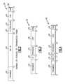
- FIG. 2is a schematic view of an example initial signal including an identifier.
- FIG. 3is a schematic view of an example signal without an identifier.
- FIG. 4is a schematic view of another example signal without an identifier that includes incremented count data.
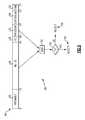
- FIG. 5is schematic view of an example method of verifying a data signal.
- a vehicle 10includes a tire pressure monitoring system 12 for providing information on conditions within tires 14 .
- Each tire 14includes a tire pressure monitoring sensor 16 that measures conditions within the tire 14 and emits a signal 22 to a receiver 18 .
- the receiver 18processes the signals 22 and alerts an operator of the vehicle should conditions within any of the tires 14 fall outside a desired range.
- the receiver 18includes an antenna 24 for receiving the signals 22 from the transmitters 16 .
- the signals 22are radio frequency signals and are therefore the length, power, and other characteristics of the signal are regulated. Further, the length and power of each of the signals 22 is directly related to the reliability of signal receipt by the receiver 18 . Shorter signals are less susceptible to potential interference. Further, a shorter signal 22 requires less power, or can be of increased strength using the same power. Accordingly, there are many advantages to reducing the overall length of the signals 22 .
- the example methodprovides for shorter transmission signals 22 during operation by eliminating transmission of the identification code.
- an initial transmission 20is sent from each of the transmitters 16 responsive to a learn prompt.
- the learn promptcan be a low frequency prompt transmission from a separate device, or can be a designated signal from the receiver 18 .
- the learn promptprompts transmission of the initial signal 20 .
- the example initial signal 20includes a preamble 26 , an identifier 28 , a function code (FC) 30 , pressure data 32 , a check portion 34 and an end of message portion 36 .
- the identifier 28includes an alphanumeric code that is unique to the transmitter that originated the message.
- the receiver 18Upon receipt of the initial transmission 20 , the receiver 18 stores the identifier 28 for comparison to subsequent transmissions. However, once the identifier 28 is known and stored by the receiver 18 it is not transmitted during normal operation. Instead, the identifier 28 is omitted.
- the transmission 22includes all the portions of the initial signal 20 except for the identification code 28 .
- the transmission 22includes the check portion 34 that provides a check of the transmission 22 that is read and acted on by the receiver.
- the check portion 34provides a count or some value that is indicative of the entire transmission 22 . That value is utilized to error proof the transmission 22 .
- Removal of the identification code 28shortens the transmission 22 and the check portion 38 reflects the shorter transmission with a value that reflects the removal of the identifier 28 .
- the transmission 22is then received by the receiver 18 .
- the first saved identifierUpon receipt of the transmission 22 by the receiver 18 , the first saved identifier is combined with the value provided in the check portion 38 . If the combination of the first saved identifier with the value provided in the check portion 38 meets a defined criteria, then the signal is recognized as originating from a first one of the transmitters 16 . If the combination with the first saved identifier does not meet the defined criteria, a second one of the saved identifiers is combined with the value, and so on until the defined criteria is met, or the signal is determined to have originated from an unrecognized transmitter.
- the check portioncomprises a cyclic redundancy check (CRC) of either 8 or 16 bits.
- CRCcyclic redundancy check
- the CRCis calculated as is known, and the remainder is added to the normal transmission.
- the receiver 18includes an algorithm that corresponds with the calculated CRC.
- the receiver 18adds the first saved identifier to the received data and performs an operation on the combination of the first saved identifier and the received data. If this combination meets the defined and expected criteria according to the specific algorithm, that transmission is determined to have been transmitted from the first transmitter. Further, operations are only commenced if the first combination according to the algorithm does not meet the desired criteria. Accordingly, the transmissions 22 become shorter, providing all the desired advantages while maintaining the verification function.
- another example transmission 40 without an identifier 28includes a count portion 42 .
- the check portion 38may combine with the stored identifiers in such a way as to meet the desired criteria according to the specific algorithm, but for the wrong transmitter 16 .
- the example transmission 40includes the count portion 42 that is incremented for each transmission. Therefore, the check portion 38 is also incremented and the count is transmitted to the receiver 18 .
- the receiver 18matches the identifier 28 with the transmission 40 and the count. If the incremented count includes a value that is expected for a specific one of the identifiers 28 , then the transmission is accepted as originating from the transmitter 16 corresponding to the saved identifier. However, if the count is not of an expected value, then the receiver 18 determines that that the signal is incorrect and disregards that signal.
- the count portion 42comprises a 4 bit counter that increments in response to each transmission.
- the count for each identifier stored in the receiver 18is stored and compared to subsequently received transmission.
- a separate countis stored for each identifier 28 . If the received count data for any transmission does not correspond with the expected value for each identifier 28 than that transmission is disregarded. Accordingly, the count portion provides an additional verification of the origin of any received transmission.
- another transmission 46is verified by comparing an identifier 28 with the pressure data portion 32 .
- the example transmission 46includes a checksum 58 for checking the validity of a transmission.
- the checksum 58is generated by a specific algorithm utilizing portions of the transmission 46 .
- the checksum 58may be generated by performing a byte-wise sum or an exclusive Or (XOR) on all the data bytes including the identifier 28 , the pressure 32 , and any other data sent within the transmission 46 .
- XORexclusive Or
- non-critical bytes that do not effect whether or not an alert is provided to the drivercan cause errant data to be incorrectly validated. Such instances can occur when utilizing an XOR of all the data bytes. If one bit is flipped in the pressure data 32 and another in the same position for another portion of the transmission is also flipped, the checksum 58 could indicate incorrectly that the data transmission is valid.
- the example process 48eliminates the possibility of incorrectly validating an incorrect transmission by generating the checksum in a byte-wise exclusive OR on the identifier 28 and the pressure 32 only as indicated at 50 . These portions of the transmission 46 include the data required to be valid in order to correctly alert an operator of an out of range condition. Because the XOR process is generated using only the pressure 32 and the identifier 28 , no flipped bytes can be undesirably validated. If a flipped byte is contained in the pressure data 32 , then the only way for the checksum 58 to validated the incorrect data if for similarly positioned byte in the identifier 28 to also be flipped.
- the transmissionwill not be recognized as indicated at 56 , by the receiver 18 , as the identifier will not match any of the previously saved identifiers.
- the transmissionwill simply be disregarded and no errant data will be received and processed. If the identifier 28 and the checksum 58 both are valid, the transmission 46 will be accepted as indicated at 54 and further processed to alert a vehicle operator, if required.
- the example transmissions and processesincrease reliability and veracity of data transmissions between the transmitters and the receiver of a tire pressure monitoring system.
Landscapes
- Engineering & Computer Science (AREA)
- Mechanical Engineering (AREA)
- Computer Networks & Wireless Communication (AREA)
- Measuring Fluid Pressure (AREA)
Abstract
Description
Claims (15)
Priority Applications (1)
| Application Number | Priority Date | Filing Date | Title |
|---|---|---|---|
| US12/035,634US7924148B2 (en) | 2007-02-23 | 2008-02-22 | Robust radio frequency signals |
Applications Claiming Priority (4)
| Application Number | Priority Date | Filing Date | Title |
|---|---|---|---|
| US90326607P | 2007-02-23 | 2007-02-23 | |
| US90399607P | 2007-02-27 | 2007-02-27 | |
| US90669707P | 2007-03-13 | 2007-03-13 | |
| US12/035,634US7924148B2 (en) | 2007-02-23 | 2008-02-22 | Robust radio frequency signals |
Publications (2)
| Publication Number | Publication Date |
|---|---|
| US20080204217A1 US20080204217A1 (en) | 2008-08-28 |
| US7924148B2true US7924148B2 (en) | 2011-04-12 |
Family
ID=39433923
Family Applications (1)
| Application Number | Title | Priority Date | Filing Date |
|---|---|---|---|
| US12/035,634Active2029-02-08US7924148B2 (en) | 2007-02-23 | 2008-02-22 | Robust radio frequency signals |
Country Status (3)
| Country | Link |
|---|---|
| US (1) | US7924148B2 (en) |
| DE (1) | DE112008000436B4 (en) |
| WO (1) | WO2008103973A1 (en) |
Cited By (4)
| Publication number | Priority date | Publication date | Assignee | Title |
|---|---|---|---|---|
| US9050862B2 (en) | 2011-10-26 | 2015-06-09 | Ateq Corporation | Universal tire pressure monitoring system tool and methods |
| US9539866B2 (en) | 2012-11-02 | 2017-01-10 | Ateq Corporation | High volume vehicle inspection system and methods |
| US11400772B2 (en) | 2020-02-26 | 2022-08-02 | Ateq | Scanning method and device for tire pressure monitoring system (tpms) protocols |
| US11845305B2 (en) | 2020-04-29 | 2023-12-19 | Ateq | Device for electronic system for monitoring the pressure of the tyres of a motor vehicle |
Families Citing this family (16)
| Publication number | Priority date | Publication date | Assignee | Title |
|---|---|---|---|---|
| CN103112324B (en) | 2007-07-03 | 2016-01-27 | 欧陆汽车系统美国有限公司 | universal tire pressure monitoring sensor |
| US8751092B2 (en)* | 2011-01-13 | 2014-06-10 | Continental Automotive Systems, Inc. | Protocol protection |
| CN103874592B (en)* | 2011-08-09 | 2018-01-30 | 大陆汽车系统公司 | Device and method for activating a positioning procedure of a tire pressure monitor |
| EP2741930B1 (en) | 2011-08-09 | 2015-11-18 | Continental Automotive Systems, Inc. | Protocol misinterpretation avoidance apparatus and method for a tire pressure monitoring system |
| US8576060B2 (en) | 2011-08-09 | 2013-11-05 | Continental Automotive Systems, Inc. | Protocol arrangement in a tire pressure monitoring system |
| EP2741928B1 (en) | 2011-08-09 | 2019-10-09 | Continental Automotive Systems, Inc. | Tire pressure monitoring apparatus and method |
| US9676238B2 (en) | 2011-08-09 | 2017-06-13 | Continental Automotive Systems, Inc. | Tire pressure monitor system apparatus and method |
| JP2013046148A (en)* | 2011-08-23 | 2013-03-04 | Tokai Rika Co Ltd | Communication method and communication system, transmission device and reception device, and tire air pressure monitoring system |
| JP2013046147A (en)* | 2011-08-23 | 2013-03-04 | Tokai Rika Co Ltd | Communication method and communication system, transmission device and reception device, and tire air pressure monitoring system |
| US9446636B2 (en) | 2014-02-26 | 2016-09-20 | Continental Automotive Systems, Inc. | Pressure check tool and method of operating the same |
| US9756592B2 (en)* | 2014-10-08 | 2017-09-05 | Nxp Usa, Inc. | Antenna delay buffering in telecommunication receivers |
| US9517664B2 (en) | 2015-02-20 | 2016-12-13 | Continental Automotive Systems, Inc. | RF transmission method and apparatus in a tire pressure monitoring system |
| DE102016213290A1 (en) | 2015-08-03 | 2017-02-09 | Continental Automotive Systems, Inc. | Apparatus, system and method for configuring a tire information sensor with a transmission protocol based on vehicle trigger characteristics |
| GB201514645D0 (en)* | 2015-08-18 | 2015-09-30 | Wheely Safe Ltd | Vehicle sensor |
| JP2018112901A (en)* | 2017-01-11 | 2018-07-19 | 太平洋工業株式会社 | Transmitter, receiver, and transmission / reception system |
| GB201817780D0 (en)* | 2018-10-31 | 2018-12-19 | V Nova Int Ltd | Methods,apparatuses, computer programs and computer-readable media for processing configuration data |
Citations (7)
| Publication number | Priority date | Publication date | Assignee | Title |
|---|---|---|---|---|
| US5428629A (en)* | 1990-11-01 | 1995-06-27 | Motorola, Inc. | Error check code recomputation method time independent of message length |
| US5463374A (en)* | 1994-03-10 | 1995-10-31 | Delco Electronics Corporation | Method and apparatus for tire pressure monitoring and for shared keyless entry control |
| US5907279A (en)* | 1996-02-08 | 1999-05-25 | U.S. Philips Corporation | Initialization of a wireless security system |
| EP1013483A2 (en) | 1998-12-25 | 2000-06-28 | Toyota Jidosha Kabushiki Kaisha | Vehicle wheel information supply device and wheel tire abnormality indicating device |
| EP1356960A2 (en) | 2002-04-22 | 2003-10-29 | Toyota Jidosha Kabushiki Kaisha | Vehicle-tire-state detection/communication apparatus and tire-data communication apparatus |
| US6810501B1 (en)* | 2001-01-03 | 2004-10-26 | Juniper Networks, Inc. | Single cycle cyclic redundancy checker/generator |
| US7511608B2 (en)* | 2005-10-21 | 2009-03-31 | Infineon Technologies Sensonor As | Tire pressure monitoring system telegram with suppressed ID |
Family Cites Families (1)
| Publication number | Priority date | Publication date | Assignee | Title |
|---|---|---|---|---|
| FR2480539B1 (en) | 1980-04-09 | 1985-09-13 | Cii Honeywell Bull | METHOD AND SYSTEM FOR TRANSMITTING SIGNED MESSAGES |
- 2008
- 2008-02-22USUS12/035,634patent/US7924148B2/enactiveActive
- 2008-02-25WOPCT/US2008/054844patent/WO2008103973A1/enactiveApplication Filing
- 2008-02-25DEDE112008000436.6Tpatent/DE112008000436B4/enactiveActive
Patent Citations (7)
| Publication number | Priority date | Publication date | Assignee | Title |
|---|---|---|---|---|
| US5428629A (en)* | 1990-11-01 | 1995-06-27 | Motorola, Inc. | Error check code recomputation method time independent of message length |
| US5463374A (en)* | 1994-03-10 | 1995-10-31 | Delco Electronics Corporation | Method and apparatus for tire pressure monitoring and for shared keyless entry control |
| US5907279A (en)* | 1996-02-08 | 1999-05-25 | U.S. Philips Corporation | Initialization of a wireless security system |
| EP1013483A2 (en) | 1998-12-25 | 2000-06-28 | Toyota Jidosha Kabushiki Kaisha | Vehicle wheel information supply device and wheel tire abnormality indicating device |
| US6810501B1 (en)* | 2001-01-03 | 2004-10-26 | Juniper Networks, Inc. | Single cycle cyclic redundancy checker/generator |
| EP1356960A2 (en) | 2002-04-22 | 2003-10-29 | Toyota Jidosha Kabushiki Kaisha | Vehicle-tire-state detection/communication apparatus and tire-data communication apparatus |
| US7511608B2 (en)* | 2005-10-21 | 2009-03-31 | Infineon Technologies Sensonor As | Tire pressure monitoring system telegram with suppressed ID |
Non-Patent Citations (1)
| Title |
|---|
| International Search Report and Written Opinion dated Jun. 13, 2008. |
Cited By (4)
| Publication number | Priority date | Publication date | Assignee | Title |
|---|---|---|---|---|
| US9050862B2 (en) | 2011-10-26 | 2015-06-09 | Ateq Corporation | Universal tire pressure monitoring system tool and methods |
| US9539866B2 (en) | 2012-11-02 | 2017-01-10 | Ateq Corporation | High volume vehicle inspection system and methods |
| US11400772B2 (en) | 2020-02-26 | 2022-08-02 | Ateq | Scanning method and device for tire pressure monitoring system (tpms) protocols |
| US11845305B2 (en) | 2020-04-29 | 2023-12-19 | Ateq | Device for electronic system for monitoring the pressure of the tyres of a motor vehicle |
Also Published As
| Publication number | Publication date |
|---|---|
| DE112008000436T5 (en) | 2010-01-07 |
| US20080204217A1 (en) | 2008-08-28 |
| DE112008000436B4 (en) | 2018-12-27 |
| WO2008103973A1 (en) | 2008-08-28 |
Similar Documents
| Publication | Publication Date | Title |
|---|---|---|
| US7924148B2 (en) | Robust radio frequency signals | |
| JP5359233B2 (en) | Tire condition monitoring method and monitoring system | |
| KR101564901B1 (en) | Protocol protection | |
| US7511608B2 (en) | Tire pressure monitoring system telegram with suppressed ID | |
| US6919798B2 (en) | Vehicle wheel information obtaining apparatus and wheel information processing apparatus | |
| CN109196833B (en) | Transmitter, receiver, and transmission/reception system | |
| US8730022B2 (en) | Tire pressure monitoring communication method and system | |
| EP2562011A1 (en) | Tire pressure monitoring redundant communication method and system | |
| US6972672B2 (en) | Tire sensor localization utilizing speed corrected frequency | |
| US11318990B2 (en) | Transmitter, receiver, and transmission/reception system | |
| US7330104B2 (en) | Tire inflation pressure monitoring device | |
| US10663954B2 (en) | Method of matching a diagnostic module to a measurement module mounted in an automotive vehicle wheel | |
| US20080111671A1 (en) | Method and apparatus for detecting use of a spare wheel | |
| JP5520843B2 (en) | Tire pressure monitoring system | |
| KR101839316B1 (en) | Tire Pressure Monitoring System for low power | |
| US11738609B2 (en) | System for determining abnormalities of TPMS and method of determination | |
| JP6568824B2 (en) | Tire condition detection device | |
| JP2007118647A (en) | Check device for tire pressure monitoring system |
Legal Events
| Date | Code | Title | Description |
|---|---|---|---|
| AS | Assignment | Owner name:CONTINENTAL AUTOMOTIVE SYSTEMS US, INC., MICHIGAN Free format text:ASSIGNMENT OF ASSIGNORS INTEREST;ASSIGNORS:COSTELLO, JOHN R.;DENIAU, JEAN-CHRISTOPHE;FARRELL, BRIAN;REEL/FRAME:020549/0224 Effective date:20080213 Owner name:CONTINENTAL AUTOMOTIVE SYSTEMS US, INC.,MICHIGAN Free format text:ASSIGNMENT OF ASSIGNORS INTEREST;ASSIGNORS:COSTELLO, JOHN R.;DENIAU, JEAN-CHRISTOPHE;FARRELL, BRIAN;REEL/FRAME:020549/0224 Effective date:20080213 | |
| FEPP | Fee payment procedure | Free format text:PAYOR NUMBER ASSIGNED (ORIGINAL EVENT CODE: ASPN); ENTITY STATUS OF PATENT OWNER: LARGE ENTITY | |
| STCF | Information on status: patent grant | Free format text:PATENTED CASE | |
| AS | Assignment | Owner name:CONTINENTAL AUTOMOTIVE SYSTEMS, INC., MICHIGAN Free format text:MERGER;ASSIGNOR:CONTINENTAL AUTOMOTIVE SYSTEMS US, INC.;REEL/FRAME:033034/0225 Effective date:20121212 | |
| FPAY | Fee payment | Year of fee payment:4 | |
| MAFP | Maintenance fee payment | Free format text:PAYMENT OF MAINTENANCE FEE, 8TH YEAR, LARGE ENTITY (ORIGINAL EVENT CODE: M1552); ENTITY STATUS OF PATENT OWNER: LARGE ENTITY Year of fee payment:8 | |
| MAFP | Maintenance fee payment | Free format text:PAYMENT OF MAINTENANCE FEE, 12TH YEAR, LARGE ENTITY (ORIGINAL EVENT CODE: M1553); ENTITY STATUS OF PATENT OWNER: LARGE ENTITY Year of fee payment:12 |