US7923996B2 - Magnetic field sensor with automatic sensitivity adjustment - Google Patents
Magnetic field sensor with automatic sensitivity adjustmentDownload PDFInfo
- Publication number
- US7923996B2 US7923996B2US12/037,393US3739308AUS7923996B2US 7923996 B2US7923996 B2US 7923996B2US 3739308 AUS3739308 AUS 3739308AUS 7923996 B2US7923996 B2US 7923996B2
- Authority
- US
- United States
- Prior art keywords
- signal
- magnetic field
- gain
- circuit
- adjustment
- Prior art date
- Legal status (The legal status is an assumption and is not a legal conclusion. Google has not performed a legal analysis and makes no representation as to the accuracy of the status listed.)
- Active, expires
Links
Images


Classifications
- G—PHYSICS
- G01—MEASURING; TESTING
- G01R—MEASURING ELECTRIC VARIABLES; MEASURING MAGNETIC VARIABLES
- G01R33/00—Arrangements or instruments for measuring magnetic variables
- G01R33/02—Measuring direction or magnitude of magnetic fields or magnetic flux
- G—PHYSICS
- G01—MEASURING; TESTING
- G01R—MEASURING ELECTRIC VARIABLES; MEASURING MAGNETIC VARIABLES
- G01R33/00—Arrangements or instruments for measuring magnetic variables
- G01R33/02—Measuring direction or magnitude of magnetic fields or magnetic flux
- G01R33/06—Measuring direction or magnitude of magnetic fields or magnetic flux using galvano-magnetic devices
- G01R33/07—Hall effect devices
- G—PHYSICS
- G01—MEASURING; TESTING
- G01R—MEASURING ELECTRIC VARIABLES; MEASURING MAGNETIC VARIABLES
- G01R33/00—Arrangements or instruments for measuring magnetic variables
- G01R33/0023—Electronic aspects, e.g. circuits for stimulation, evaluation, control; Treating the measured signals; calibration
- G01R33/0041—Electronic aspects, e.g. circuits for stimulation, evaluation, control; Treating the measured signals; calibration using feed-back or modulation techniques
- G—PHYSICS
- G01—MEASURING; TESTING
- G01R—MEASURING ELECTRIC VARIABLES; MEASURING MAGNETIC VARIABLES
- G01R33/00—Arrangements or instruments for measuring magnetic variables
- G01R33/02—Measuring direction or magnitude of magnetic fields or magnetic flux
- G01R33/06—Measuring direction or magnitude of magnetic fields or magnetic flux using galvano-magnetic devices
- G—PHYSICS
- G01—MEASURING; TESTING
- G01R—MEASURING ELECTRIC VARIABLES; MEASURING MAGNETIC VARIABLES
- G01R35/00—Testing or calibrating of apparatus covered by the other groups of this subclass
Definitions
- This inventionrelates generally to magnetic field sensors and, more particularly, to magnetic field sensors having circuitry to sense and adjust a sensitivity of the magnetic field sensors to a magnetic field.
- Magnetic field sensorsemploy a variety of types of magnetic field sensing elements, for example, Hall effect elements and magnetoresistance elements, often coupled to a variety of electronics, all disposed over a common substrate.
- a magnetic field sensing element(and a magnetic field sensor) can be characterized by a variety of performance characteristics, one of which is a sensitivity, which can be expressed in terms of an output signal amplitude versus a magnetic field to which the magnetic field sensing element is exposed.
- the sensitivity of a magnetic field sensing element, and therefore, of a magnetic field sensoris known to change in relation to a number of parameters.
- the sensitivitycan change in relation to a change in temperature of the magnetic field sensing element.
- the sensitivitycan change in relation to a strain imposed upon the substrate over which the magnetic field sensing element is disposed.
- Such a straincan be imposed upon the substrate at the time of manufacture of an integrated circuit containing the substrate.
- the straincan be imposed by stresses caused by curing of molding compounds used to form an encapsulation of the substrate, e.g., a plastic encapsulation.
- a magnetic field sensorwhich includes a magnetic field sensing element, can measure, either directly or indirectly, a sensitivity of the magnetic field sensing element, and can adjust a sensitivity of the magnetic field sensor accordingly. Therefore, the magnetic field sensor maintains a sensitivity to magnetic fields that is generally invariant in the presence of temperature excursions or in the presence of manufacturing steps, both of which might otherwise tend to change the sensitivity of the magnetic field sensor.
- a magnetic field sensorin accordance with one aspect of the present invention, includes a magnetic field sensing element supported by a substrate.
- the magnetic field sensing elementis for generating an output signal comprising a magnetic-field-responsive signal portion.
- the magnetic-field-responsive signal portionhas a sensitivity to a first magnetic field.
- the magnetic field sensoralso includes a feedback circuit, which includes a current conductor supported by the substrate and proximate to the magnetic field sensing element.
- the current conductoris for generating a second magnetic field.
- the feedback circuitalso includes a gain-calculation circuit configured to generate a gain-adjustment signal responsive to the second magnetic field.
- the magnetic field sensoralso includes a gain-adjustment circuit supported by the substrate and having a gain-adjustment node coupled to receive the gain-adjustment signal.
- the gain-adjustment circuitis configured to adjust the sensitivity of the magnetic-field-responsive signal portion in response to the gain-adjustment signal.
- a magnetic field sensorin accordance with another aspect of the present invention, includes a magnetic field sensing element supported by a substrate.
- the magnetic field sensing elementis for generating an output signal comprising a magnetic-field-responsive signal portion.
- the magnetic-field-responsive signal portionhas a sensitivity to a first magnetic field.
- the magnetic field sensoralso includes a feedback circuit.
- the feedback circuitincludes a first piezoresistor supported by the substrate.
- the first piezoresistorhas a node at which a first piezoelectric output signal is generated.
- the first piezoelectric output signalis responsive to a strain of the substrate in a first direction.
- the feedback circuitalso includes a second piezoresistor supported by the substrate.
- Each one of the first and second piezoresistorshas a respective primary response axis, wherein the first and second piezoresistors are disposed in a relative orientation so that their respective primary response axes are generally perpendicular.
- the second piezoresistorhas a node at which a second piezoelectric output signal is generated.
- the second piezoelectric output signalis responsive to a strain of the substrate in a second direction generally perpendicular to the first direction.
- the feedback circuitfurther includes a combining circuit having first and second input nodes coupled to receive signals related to the first and second piezoelectric output signals and having an output node at which a gain-adjustment signal is generated.
- the magnetic field sensoralso includes a gain-adjustment circuit supported by the substrate, which has a gain-adjustment node coupled to receive the gain-adjustment signal.
- the gain-adjustment circuitis configured to adjust the sensitivity of the magnetic-field-responsive signal portion in response to the gain-adjustment signal.
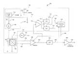
- FIG. 1is a block diagram of a circuit having a magnetic field sensing element, here a Hall effect element, coupled to a gain-adjustment circuit, wherein the gain-adjustment circuit is coupled to a feedback circuit configured to provide a gain-adjustment signal to adjust a gain of the gain-adjustment circuit, wherein, in some embodiments, the feedback circuit includes a temperature threshold circuit and or a power-on circuit;
- a magnetic field sensing elementhere a Hall effect element
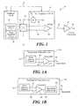
- FIG. 1Ais a block diagram showing an exemplary embodiment of a temperature threshold circuit that can be used as the temperature threshold circuit of FIG. 1 ;
- FIG. 1Bis a block diagram showing another exemplary embodiment of a temperature threshold circuit that can be used as the temperature threshold circuit of FIG. 1 ;
- FIG. 1Cis a block diagram showing a combined power-on temperature threshold circuit that can be used in place of the power-on circuit and the temperature threshold circuit of FIG. 1 ;
- FIG. 2is a block diagram of a particular embodiment of the circuit of FIG. 1 , wherein the feedback circuit includes two piezoresistors, and wherein the gain adjustment circuit comprises a gain adjustable preamplifier;
- FIG. 2Ais a block diagram of another particular embodiment of the circuit of FIG. 1 , wherein the feedback circuit includes the two piezoresistors, and wherein the gain adjustment circuit comprises an adjustable current source coupled to the Hall effect element;
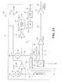
- FIG. 3is a block diagram of another particular embodiment of the circuit of FIG. 1 , wherein the feedback circuit includes a conductor proximate to the Hall effect element, and wherein the gain adjustment circuit comprises a gain adjustable preamplifier;
- FIG. 3Ais a block diagram of another particular embodiment of the circuit of FIG. 1 , wherein the feedback circuit includes the conductor proximate to the Hall effect element, and wherein the gain adjustment circuit comprises an adjustable current source coupled to the Hall effect element;
- FIG. 3Bis a block diagram of another particular embodiment of the circuit of FIG. 1 , wherein the feedback circuit includes a second Hall effect element and wherein the gain adjustment circuit comprises an adjustable current source coupled to the Hall effect element;
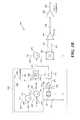
- FIG. 4is a block diagram of another particular embodiment of the circuit of FIG. 1 , wherein the feedback circuit includes two piezoresistors and also includes a respective conductor proximate to each piezoresistor, and wherein the gain adjustment circuit comprises an adjustable current source coupled to the Hall effect element;
- FIG. 4Ais a block diagram of another particular embodiment of the circuit of FIG. 1 , wherein the feedback circuit includes the two piezoresistors and also includes the respective conductor proximate to each piezoresistor, and wherein the gain adjustment circuit comprises the adjustable current source coupled to the Hall effect element;
- FIG. 4Bis a block diagram of another particular embodiment of the circuit of FIG. 1 , wherein the feedback circuit includes two piezoresistors and also includes a conductor proximate to the Hall effect element, and wherein the gain adjustment circuit comprises an adjustable current source coupled to the Hall effect element;
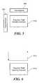
- FIG. 5is a block diagram showing a magnetic field sensing element in relation to two piezoresistors
- FIG. 6is a block diagram showing a magnetic field sensing element and a current conductor proximate to the magnetic field sensing element
- FIG. 7is a block diagram showing a magnetic field sensing element, two piezoresistors, and a respective conductor proximate to each piezoresistor;
- FIG. 8is a block diagram showing a magnetic field sensing element and a current conductor formed in multiple loops around the magnetic field sensing element.
- magnetic field sensoris used to describe a circuit that includes a “magnetic field sensing element.” Magnetic field sensors are used in a variety of applications, including, but not limited to, a current sensor that senses a magnetic field generated by a current flowing in a current conductor, a magnetic switch that senses the proximity of a ferromagnetic object, a rotation detector that senses passing ferromagnetic articles, for example, magnetic domains of a ring magnet, and a magnetic field sensor that senses a magnetic field density of a magnetic field.
- the term “magnetic field sensor”is used synonymously herein with the phrase “circuit for sensing a magnetic field.”
- magnetic field sensing elementsare shown and described below to be Hall effect elements, in other arrangements, the magnetic field sensing elements can be, but are not limited to, Hall effect elements, magnetoresistance elements, or magnetotransistors.
- Hall effect elementsfor example, a planar Hall element, and a vertical Hall element.
- magnetoresistance elementsfor example, a giant magnetoresistance (GMR) element, an anisotropic magnetoresistance element (AMR), a tunneling magnetoresistance (TMR) element, and a magnetic tunnel junction (MTJ).
- GMRgiant magnetoresistance
- AMRanisotropic magnetoresistance element
- TMRtunneling magnetoresistance
- MTJmagnetic tunnel junction
- piezoresistoris used to describe a circuit element that has a resistance related to a strain of the piezoresistor.
- Conventional piezoresistorsare known.
- the piezoresistorscan also have a resistance related to a magnetic field experienced by the piezoresistor, and in this way, can also function as a so-called “magnetoresistor.”
- the piezoresistors described belowcan be made larger (e.g., longer) than conventional piezoresistors, in order to improve sensitivity of the piezoresistors to magnetic fields.
- the term “piezoresistors”also includes conventional magnetoresistance elements.
- an exemplary circuit 10 for sensing a magnetic fieldincludes a magnetic field sensing element 20 , here a Hall effect element.
- the Hall effect element 20is coupled to receive a drive current 22 from a current source 24 and configured to generate a differential Hall voltage signal 26 , 28 , which is coupled to a gain-adjustment circuit 14 .
- the gain-adjustment circuit 14includes the current source 24 and also includes a preamplifier 30 .
- the preamplifier 30is configured to amplify the differential input signal 26 , 28 and to generate an amplified signal 32 .
- the circuit 10can also include another circuit element 34 , which, in some arrangements, is a (linear) amplifier, and which, in other arrangements, is a comparator.
- the circuit 10also includes a feedback circuit 12 , which is configured to sense, either directly or indirectly, a sensitivity of the Hall effect elements 20 .
- the feedback circuitis configured to generate a gain-adjustment signal 16 coupled to the gain-adjustment circuit.
- either one of (or both of) the current source 24 or the preamplifier 30can be used as a gain adjustment element, which can affect a magnitude of the amplified signal 32 in response to the gain-adjustment signal 16 .
- the feedback circuit 12can include a temperature threshold circuit 18 .
- the feedback circuit 12in some embodiments, can also include a power-on circuit 19 .
- the temperature threshold circuit 18is configured to affect the gain-adjustment signal 16 , for example, so that the gain-adjustment signal 16 controls the gain of the gain-adjustment circuit 14 only when a temperature of a substrate over which the circuit 10 is disposed reaches a temperature above a temperature threshold.
- the power-on circuit 18is also configured to affect the gain-adjustment signal 16 , for example, so that the gain-adjustment signal 16 controls the gain of the gain-adjustment circuit 14 only for a period of time shortly following power being applied to the circuit 10 .
- an exemplary temperature threshold circuit 40can be the same as or similar to the temperature threshold circuit 18 of FIG. 1 .
- the temperature threshold circuit 40can include a temperature sensing element 42 configured to generate a temperature signal 44 responsive to a temperature of a substrate over which the temperature-sensing element 42 is disposed.
- a comparator 47is coupled to receive the temperature signal 44 and to compare the temperature signal 44 to a threshold signal 46 .
- the comparator 47is configured to generate a temperature enable signal 48 , which can, for example, take on a first state when the temperature signal 44 is below the temperature threshold signal 46 and a second state when the temperature signal 44 is above the temperature threshold signal 46 .
- the temperature threshold circuit 50can be the same as or similar to the temperature threshold circuit 18 of FIG. 1 .
- the temperature threshold circuit 50can include a temperature sensing element 52 configured to generate a temperature signal 54 responsive to a temperature of a substrate over which the temperature-sensing element 52 is disposed.
- a comparator 58is coupled to receive the temperature signal 54 and to compare the temperature signal 54 to a threshold signal 56 .
- the comparator 58is configured to generate a comparison signal 60 , which can, for example, take on a first state when the temperature signal 54 is below the temperature threshold signal 56 and a second state when the temperature signal 54 is above the temperature threshold signal 56 .
- the temperature threshold circuit 50can also include a monostable multivibrator 62 coupled to receive the comparison signal 60 and configured to generate a temperature enable signal 64 .
- the temperature enable signal 64is a pulse signal beginning at or near to a time when the temperature signal 54 crosses a value of temperature threshold signal 56 and ending at a time determined by characteristics of the monostable multivibrator 62 .
- the pulse signal 64has a duration of about one millisecond.
- circuit 40 of FIG. 1Acan generate the temperature enable signal 48 as a substantially static signal, while the circuit 50 of FIG. 1B can generate the temperature enable signal 48 as pulse signal.
- a combined power-on and temperature threshold circuit 700provides a change of state of an enable signal 742 both at the time of power up and also at the time of temperature excursions.
- the circuit 700includes a power-on circuit 702 configured to generate a power-on signal 704 indicative of a power up of a circuit, for example, of the circuit 10 of FIG. 1 .
- Power-on circuitsthat can be used as the power-on circuit 19 of FIG. 1 or the power-on circuit 702 of FIG. 1C are known, and therefore, are not described further. However, it should be recognized that the power-on circuits 19 , 702 can, in some embodiments, generate a substantially static power-on enable signal, and, in other embodiments, can generate the power-on enable signal as a pulse signal near to a time that power is applied to a circuit, for example, the circuit 10 of FIG. 1 .
- the circuit 700also includes a monostable multivibrator 706 coupled to receive the power-on signal 704 and configured to generate a power-on binary pulse signal 708 having a predetermined period.
- the power-on binary pulse signal 708is coupled to an OR gate 714 configured to generate a binary sampling signal 716 .
- the circuit 700also includes a temperature sensing element 744 configured to generate a temperature signal 746 indicative of a temperature of a circuit, for example, the circuit 10 of FIG. 1 .
- the temperature signal 746is received by a sample-and-hold circuit 748 , which samples the temperature signal 746 during one state of the binary sampling signal 716 , resulting in a held temperature signal 750 during the other state of the binary sampling signal 716 .
- An offset circuit 718is coupled to receive the held temperature signal 750 .
- the offset circuit 718includes first and second voltage sources 722 , 724 , respectively, which are coupled so as to generate a positive offset held temperature signal 720 and a negative offset held temperature signal 726 .
- the positive offset held temperature signal 720is a predetermined amount above the held temperature signal 750 , for example, one hundred millivolts
- the negative offset held temperature signal 726is a predetermined amount below the held temperature signal 750 , for example, one hundred millivolts.
- the first and second voltage sources 722 , 724can be different, resulting in the positive offset held temperature signal 720 and the negative offset held temperature signal 72726 being different predetermined amounts away form the held temperature signal 750 .
- the positive offset held temperature signal 720 and the negative offset held temperature signal 726are received by a window comparator 730 .
- Window comparatorscan be configured with a variety of topologies and the topology shown is merely representative.
- the window comparator 730is also coupled to receive the temperature signal 746 .
- the window comparator 730is configured to generate a change in state of a binary window comparator output signal 742 whenever the temperature signal 752 transitions outside of a window defined by the boundaries of the positive offset held temperature signal 720 and the negative offset held temperature signal 726 .
- the binary window comparator output signal 742is indicative of a temperature excursion experiences by the temperature sensing element 744 .
- the binary window comparator output signal 742also has a change of state near to a time of power up of the circuit 700 .
- the temperature signal 752can rapidly achieve a value representative of the temperature, while the positive offset held temperature signal 720 and the negative offset held temperature signal 726 can more slowly approach steady values. Therefore, initially, at power up, the binary window comparator output signal 742 may be, for example, high. As the positive offset held temperature signal 720 and the negative offset held temperature signal 726 achieve more steady values, the binary window comparator output signal 742 may transition to a low state.
- the binary window comparator output signal 742changes state.
- the binary window comparator output signal 742can be used as an “enable” signal in circuits shown in subsequent figures.
- a gain adjustmenti.e., a gain calibration
- the enable signal 742can serve to initiate such a calibration at or near to the time of a power up and also at or near to a time of a temperature excursion sensed by the temperature sensing element 744 .
- the term “enable” signalis used to refer either to a temperature enable signal, to a power-on enable signal, or to a combination of both.
- the enable signal 742is coupled to another monostable multivibrator 712 , which generates a temperature excursion binary pulse signal 710 .
- the temperature excursion binary pulse signal 710is also received by the OR gate 714 , resulting in another pulse within the binary sample signal 748 when the enable signal 742 has a change of state due to a temperature excursion.
- the pulsed binary sample signal 716 resulting from the temperature excursionresults in the held temperature signal 750 taking on a new value and therefore, the window defined by the boundaries of the positive offset held temperature signal 720 and the negative offset held temperature signal 726 taking one a new position surrounding the held temperature signal 750 .
- the enable signal 742changes back to its original state.
- the enable signal 742can cause any of the circuits described below to automatically calibrate (e.g., gain adjust) both at power up and when experiencing a predetermined temperature excursion, either a positive or a negative temperature excursion.
- a circuit 70 for sensing a magnetic fieldcan be the same as or similar to the circuit 10 of FIG. 1 and can include a feedback circuit 72 , which can be the same as or similar to the feedback circuit 12 of FIG. 1 .
- the feedback circuit 72is described more fully below.
- the circuit 70includes a magnetic field sensing element 108 , here a Hall effect element.
- the Hall effect element 108is coupled to receive a drive current signal 112 from a current source 110 and configured to generate a differential Hall voltage signal 114 , 116 , which is coupled to a preamplifier 118 .
- the preamplifier 118is used as a gain-adjustment element having a gain responsive to a gain-adjustment signal 106 generated by the feedback circuit 72 .
- the preamplifier 118is configured to amplify the differential input signal 114 , 116 and to generate an amplified signal 120 .
- the circuit 70can also include another circuit element 122 coupled to receive the amplified signal 120 and configured to generate an output signal 124 .
- the circuit element 122is a (linear) amplifier, and, in other arrangements, the circuit element 122 is a comparator.
- the feedback circuit 72can include first and second piezoresistors 80 , 86 , respectively.
- a piezoresistorwill be recognized to be a circuit element having a resistance that varies in relation to a strain experienced by the piezoresistor.
- the substratecan experience a stress and a resulting strain.
- the straincan affect a sensitivity of the magnetic field sensing element 108 .
- the feedback circuit 72 , and the piezoresistors 80 , 86in particular, can measure the strain, and the feedback circuit 72 can generate the feedback signal 106 related to the strain.
- the first piezoresistor 80can be coupled to receive a first current signal 78 from a first current source 76 , which results in a first voltage signal 78 a .
- the feedback circuit 72can also include a first amplifier 81 coupled to receive the first voltage signal 78 a and configured to generate a first amplified signal 94 .
- the second piezoresistor 86can be coupled to receive a second current signal 84 from a second current source 82 , which results in a second voltage signal 84 a .
- the feedback circuit 72can also include a second amplifier 90 coupled to receive the second voltage signal 84 a and configured to generate a second amplified signal 92 .
- the feedback circuit 72can further include a combining circuit 96 coupled to receive the first and second amplified signals 94 , 92 , respectively, and configured to generate an output signal 98 .
- the feedback circuit 72includes a sample-and-hold circuit 104 coupled to receive the output signal 98 .
- the sample-and-hold circuit 104can be coupled to receive a pulse signal 102 from a pulse generator 100 , a state or transition of which results in the sample-and-hold circuit 104 sampling the output signal 98 and generating the gain-control signal 106 accordingly.
- the pulse generator 100can be responsive to an enable signal 88 , which can be a temperature enable signal, a power-on enable signal, or a combination of both.
- the circuit 70can include one or both of a temperature threshold circuit and/or a power-on circuit, which are described above in conjunction with FIGS. 1-1B .
- the temperature threshold circuit and/or a power-on circuitare not shown for clarity; instead, only the enable signal 88 is shown.
- the sample-and-hold circuit 104can sample the output signal 98 to generate the gain-adjustment signal 106 during times when the temperature enable signal or the power-on enable signal are active, e.g., when the temperature of the circuit has increased above a temperature threshold or when power has recently been applied to the circuit 70 . Conversely, the sample-and-hold circuit 104 can hold the gain-adjustment signal 106 during times when the temperature enable signal or the power-on enable signal are inactive, e.g., when the temperature decreases from being above the temperature threshold to being below the temperature threshold or at a time after power has been applied to the circuit 70 .
- the enable signal 88can also be received by the first and second current sources 76 , 82 , respectively, causing the first and second current sources 76 , 82 to generate the first and second current signals 78 , 84 only when the enable signal 88 is active.
- the circuit 70can conserve power at times when gain adjustment is not required, for example, when the temperature of the circuit 70 has not exceeded the temperature threshold.
- the first and second piezoresistors 80 , 86are arranged orthogonally over the substrate on which they are disposed.
- a value of the first voltage signal 78 ais related to a strain in a first direction parallel to a major surface of the substrate and a value of the second voltage signal 84 a is related to a strain in a second direction parallel to a major surface of the substrate and orthogonal to the first direction.
- a strain of the substrate in any direction parallel to a major surface of the substratecan be sensed by the piezoresistors 80 , 86 .
- a predetermined relationship between the first current signal 78 and the second current signal 84is selected in accordance with an expected relationship between the strain of the substrate in the first direction and the strain of the substrate in the second direction when the substrate is subjected to a temperature excursion.
- the combining circuit 96provides the output signal 98 and resulting gain-adjustment signal 106 as a sum of the amplified signals 94 , 92 . In other arrangements, the combining circuit 96 provides the output signal 98 and resulting gain-adjustment signal 106 as a root-mean-square (RMS) sum of the amplified signals 94 , 92 . In still other arrangements, particularly arrangements for which the sensitivity of the magnetic field sensing element 108 is a non-linear function of the strain of the substrate over which it is disposed, the combining circuit 96 can combine the amplified signals 94 , 92 in other ways.
- RMSroot-mean-square
- the gain-adjustment signal 106adjusts the gain of the preamplifier 118 in relation to the strains sensed by the piezoresistors 80 , 86 , tending to keep the sensitivity of the circuit 70 more constant in the presence of strains and temperature excursions than if the gain-adjustment signal 106 were not provided.
- a selected portion 140 of the feedback circuit 72can be powered on or off, for example, by way of a switch 142 , depending upon a state of the enable signal 88 . Powering off the selected portion 140 can conserve power at times when gain adjustment is not required. It will be appreciated that the selected portion 140 excludes the sample-and-hold circuit 104 and the pulse generator 100 .
- the sample-and-hold circuit 104can hold the gain-adjustment signal 106 at a steady value during times when the temperature enable signal or the power-on enable signal (i.e., the enable signal 88 ) are inactive, e.g., when the temperature decreases from being above the temperature threshold to being below the temperature threshold or at a time after power has been applied to the circuit 70 , even when the selected portion 140 is entirely powered off.
- the temperature enable signal or the power-on enable signali.e., the enable signal 88
- a selected portion 210 and a switch 212are shown in FIG. 3 below
- a selected portion 230 and a switch 232are shown in FIG. 3A below
- a selected portion 296 and a switch 298are shown in FIG. 3B below
- a selected portion 370 and a switch 372are shown in FIG. 4 below
- a selected portion 490 and a switch 492are shown in FIG. 4A below
- a selected portion 590 and a switch 592are shown in FIG. 4B below, each of which can provide the functions and advantages of the selected portion 140 and the switch 142 of FIG. 2 .
- another circuit 130 for sensing a magnetic fieldcan be the same as or similar to the circuit 10 of FIG. 1 and can include the feedback circuit 72 of FIG. 2 .
- gain adjustmentis provided by way of an adjustable current source 136 that generates an adjustable current signal 140 to the Hall effect element 108 in response to the gain-adjustment signal 106 .
- a fixed gain preamplifier 142replaces the gain-adjustable preamplifier 118 of FIG. 2 .
- Operation of the circuit 130is substantially the same as operation described above in conjunction with FIG. 2 .
- a circuit 150 for sensing a magnetic fieldcan be the same as or similar to the circuit 10 of FIG. 1 and can include a feedback circuit 152 , which can be the same as or similar to the feedback circuit 12 of FIG. 1 .
- the feedback circuit 152is described more fully below.
- the circuit 150includes a magnetic field sensing element 166 , here a Hall effect element.
- the Hall effect element 166is coupled to receive a drive current signal 192 from a current source 190 and configured to generate a differential Hall voltage signal 194 , 196 , which is coupled to a preamplifier 198 .
- the preamplifier 198is used as a gain-adjustment element having a gain responsive to a gain-adjustment signal 186 generated by the feedback circuit 152 .
- the preamplifier 198is configured to amplify the differential input signal 194 , 196 and to generate an amplified signal 200 .
- the circuit 150can also include a low pass filter 202 coupled to receive the amplified signal 200 and configured to generate a filtered signal 204 .
- the circuit 150can also include another circuit element 206 coupled to receive the filtered signal 204 and configured to generate an output signal 208 .
- the circuit element 206is a (linear) amplifier, and, in other arrangements, the circuit element 206 is a comparator.
- the feedback circuit 152can include a conductor 164 , here shown to form a loop around the Hall effect element 166 .
- the conductor 164can be coupled to receive a current signal 162 from a current source 160 .
- the current source 160can be coupled to receive a pulse signal 158 generated by a pulse generator 154 .
- the pulse signal 158can result in a pulse current signal 162 .
- the pulse current signalhas two states, a first state during which essentially zero current flows into the conductor 164 , and a second state during which a predetermined current flows into the conductor 164 .
- a duty cycle of the second statecan be small, for example, in the range of about one percent to about five percent.
- a frequency of the pulse current signal 162is in the range of about 25 kHz to 500 kHz.
- the Hall effect element 166when the current source 160 is in the first state and generating essentially zero current, the Hall effect element 166 is responsive only to a magnetic field that it is intended to measure, for example, a magnetic field resulting from a current passing through a current-carrying conductor (or, more simple, a current conductor) as would be found in conjunction with a current sensor.
- the Hall effect element 166when the current source 160 is in the second state and generating the predetermined current, the Hall effect element 166 is responsive not only to the magnetic field that it is intended to measure, but also to a magnetic field generated by the predetermined current passing through the conductor 164 . Therefore, the amplified signal 200 is a sum of a signal representative of the magnetic field that the circuit 150 is intended to measure combined with pulses representative of the magnetic field resulting from current signal 162 having the above-described current pulses.
- the amplified signal 200is received by an amplifier 178 configured to generate another amplified signal 175 .
- First and second sample-and-hold circuits 174 , 178are coupled to receive the amplified signal 175 and to generate first and second sampled signals 180 , 192 , respectively.
- the first sample-and-hold circuit 174receives the pulse signal 158 and samples during a particular state of the pulse signal 158 , for example, at times when the current signal 162 has a current pulse.
- the second sample-and-hold circuit 176receives an inverted pulse signal 172 generated by an inverter 170 and samples during a particular state of the inverted pulse signal 172 , for example, at times when the current signal 162 has no current pulse.
- the second sampled signal 182is representative of the magnetic field that the circuit 150 is intended to measure
- the first sampled signal 180is representative of the magnetic field that the circuit 150 is intended to measure in combination with the magnetic field resulting from current signal 162 having the above-described current pulses.
- the feedback circuit 152can include a combining circuit 184 coupled to receive the first and second sampled signals 180 , 182 .
- the combining circuit 184is configured to generate the gain-adjustment signal 186 coupled to the preamplifier 198 .
- the combining circuit 184provides the gain-adjustment signal 186 as a difference of the first and second sampled signals 180 , 182 , and is, therefore, representative of only the magnetic field resulting from current signal 162 having the above-described current pulses.
- the gain-adjustment signal 186is directly representative of a sensitivity of the Hall effect element 166 to the magnetic field resulting from the above-described current pulses.
- gain-calculation circuitis used to describe portions of the feedback circuit 152 not including the conductor 164 , current source 160 , or pulse generator 154 .
- the low pass filter 202essentially removes the pulses in the amplified signal 200 resulting from the above-described current pulses, leaving the filtered signal 204 representative of only the magnetic field that the circuit 150 is intended to measure. It will be understood that the filtered signal 204 is similar to the second sampled signal 182 , and in other embodiments, either signal can be used interchangeably. Thus, the signal 204 is shown to be coupled with a dashed line to the combining circuit 184 .
- the gain-adjustment signal 186adjusts the gain of the preamplifier 198 in relation to the directly measured sensitivity of the Hall effect element 164 , tending to keep the sensitivity of the circuit 150 more constant in the presence of strain-related changes in the sensitivity of the Hall effect element 166 , or other changes in the sensitivity of the Hall effect element 166 , than if the gain-adjustment signal 186 were not provided.
- the sensitivity of the Hall effect element 166can be directly affected by temperature, apart from the strains imposed upon Hall effect element 166 due to the temperature.
- mobility of the Hall effect elementcan be related to temperature.
- the circuit 150directly measures the sensitivity of the Hall effect element 166 , the circuit 150 is configured to adjust the gain of the preamplifier 198 to account for changes in sensitivity of the Hall effect element 166 resulting from any source of change.
- the pulse generator 154can be coupled to receive an enable signal 156 , which, as described above in conjunction with FIG. 2 , can be a temperature enable signal, a power-on enable signal, or a combination of both.
- the circuit 150can include one or both of a temperature threshold circuit and/or a power-on circuit, which are described above in conjunction with FIGS. 1-1B .
- the temperature threshold circuit and/or a power-on circuitare not shown for clarity; instead, only the enable signal 156 is shown.
- another circuit 220 for sensing a magnetic fieldcan be the same as or similar to the circuit 10 of FIG. 1 and can include the feedback circuit 152 of FIG. 3 .
- gain adjustmentis provided by way of an adjustable current source 222 that generates an adjustable current signal 224 to the Hall effect element 166 in response to the gain-adjustment signal 186 .
- a fixed gain preamplifier 226replaces the gain-adjustable preamplifier 198 of FIG. 3 .
- Operation of the circuit 220is substantially the same as operation described above in conjunction with FIG. 3 .
- a circuit 240 for sensing a magnetic fieldlike the circuit 150 of FIG. 3 , achieves a gain adjustment by a direct measurement of a sensitivity of a Hall effect element.
- the element used to directly measure the sensitivityis a second Hall effect element 254 , not the Hall effect element 280 intended to measure a magnetic field.
- the circuit 240can include a feedback circuit 242 , which can be the same as or similar to the feedback circuit 12 of FIG. 1 .
- the feedback circuit 242is described more fully below.
- the circuit 240includes a magnetic field sensing element 280 , here a Hall effect element.
- the Hall effect element 280is coupled to receive a drive current signal 278 from a current source 276 and configured to generate a differential Hall voltage signal 282 , 284 , which is coupled to a preamplifier 286 .
- the preamplifier 286is configured to generate an amplified signal 288 .
- the circuit 240can also include another circuit element 290 coupled to receive the amplified signal 288 and configured to generate an output signal 290 .
- the circuit element 290is a (linear) amplifier, and, in other arrangements, the circuit element 290 is a comparator.
- the feedback circuit 242can include a secondary magnetic field sensing element 254 , here a Hall effect element.
- the secondary Hall effect element 254is coupled to receive a drive current signal 258 from a current source 256 and configured to generate a differential Hall voltage signal 264 , 266 , which is coupled to a second preamplifier 268 .
- a current conductor 252here shown as a coil, is proximate to the secondary Hall effect element 254 .
- the current conductor 252receives a current signal 250 from a current source 246 .
- the differential Hall voltage signal 264 , 266is representative of a magnetic field generated by the current conductor 252 and of a sensitivity of the second Hall effect element 254 .
- the circuit 240includes a magnetic shield disposed proximate to the second Hall effect element 254 to reduce the effect upon the secondary Hall effect element 254 of magnetic fields other than the magnetic field generated by the current conductor 252 .
- the second preamplifier 268is configured to generate an amplified signal 270 .
- the feedback circuit 242can include a sample-and-hold circuit 272 coupled to receive the amplified signal 270 and configured to generate a gain-adjustment signal 274 .
- the current source 276generates the current signal 278 as an adjustable current signal 278 to the Hall effect element 280 in response to the gain-adjustment signal 274 .
- the gain-adjustment signal 274adjusts the current source 276 , tending to keep the sensitivity of the circuit 240 more constant in the presence of changes in the sensitivity of the secondary Hall effect element 254 , which are related to changes in sensitivity of the Hall effect element 280 , than if the gain-adjustment signal 274 were not provided.
- the pulse generator 260can be coupled to receive an enable signal 248 , which, as described above in conjunction with FIG. 2 , can be a temperature enable signal, a power-on enable signal, or a combination of both.
- the circuit 240can include one or both of a temperature threshold circuit and/or a power-on circuit, which are described above in conjunction with FIGS. 1-1B .
- the temperature threshold circuit and/or a power-on circuitare not shown for clarity; instead, only the enable signal 248 is shown.
- the enable signal 248can also be received by the first and second current sources 246 , 256 , respectively, causing the first and second current sources 246 , 256 to generate the first and second current signals 250 , 258 only when the enable signal 248 is active, i.e., in a particular state.
- the circuit 240can conserve power at times when gain adjustment is not required, for example, when the temperature of the circuit 240 has not exceeded the temperature threshold.
- the gain-adjustment signal 274can be applied to a gain-adjustable preamplifier in place of the preamplifier 286 .
- a circuit 300 for sensing a magnetic fieldcan be the same as or similar to the circuit 10 of FIG. 1 and can include a feedback circuit 302 , which can be the same as or similar to the feedback circuit 12 of FIG. 1 .
- the feedback circuit 302is described more fully below.
- the circuit 300includes a magnetic field sensing element 352 , here a Hall effect element.
- the Hall effect element 352is coupled to receive a drive current signal 350 from an adjustable current source 348 and configured to generate a differential Hall voltage signal 354 , 356 , which is coupled to a preamplifier 358 .
- the adjustable current source 348is responsive to a gain-adjustment signal 344 generated by the feedback circuit 302 and provides a gain adjustment of the differential Hall voltage signal 354 , 356 .
- the preamplifier 358is configured to generate an amplified signal 360 .
- the circuit 300can also include another circuit element 362 coupled to receive the amplified signal 360 and configured to generate an output signal 364 .
- the circuit element 362is a (linear) amplifier, and, in other arrangements, the circuit element 362 is a comparator.
- the feedback circuit 302can include first and second piezoresistors 312 , 320 , respectively.
- first and second piezoresistors 312 , 320can affect a sensitivity of the magnetic field sensing element 352 .
- the feedback circuit 302 , and the piezoresistors 312 , 320in particular, can measure the strain, and the feedback circuit 302 can generate the feedback signal 344 related to the strain.
- the first piezoresistor 312can be coupled to receive a first current signal 310 from a first current source 308 , which results in a first voltage signal 310 a .
- the feedback circuit 302can also include a first amplifier 327 coupled to receive the first voltage signal 310 a and configured to generate a first amplified signal 328 .
- the second piezoresistor 320can be coupled to receive a second current signal 318 from a second current source 316 , which results in a second voltage signal 318 a .
- the feedback circuit 302can also include a second amplifier 330 coupled to receive the second voltage signal 318 a and configured to generate a second amplified signal 332 .
- the circuit 300can further include series coupled first and second conductors 314 , 322 , respectively, here shown as coils, proximate to the first and second piezoresistors 312 , 320 .
- first and second conductors 314 , 322are coupled to receive a current signal 326 from a current source 324 .
- the current signal 326 passing through the conductors 314 , 322results in a magnetic field at the piezoresistors 312 , 320 .
- the first and second amplified signals 328 , 332are indicative of strains experienced by the first and second piezoresistors 312 , 320 respectively, (e.g., have voltages that vary in proportion to the respective strains), and are also indicative of magnetic field responses (i.e., sensitivity) of the first and second piezoresistors 312 , 320 , respectively, (e.g., have voltages that vary in proportion to the current signal 326 ).
- changes in the magnetic field sensitivity of the first and second piezoresistors 312 , 320tend to be related to changes in the magnetic field sensitivity of the magnetic field sensing element 352 .
- the circuit 300tends to more directly measure changes in magnetic field sensitivity than the circuit 70 of FIG. 2 .
- the feedback circuit 302can further include a combining circuit 334 coupled to receive the first and second amplified signals 328 , 332 , respectively, and configured to generate an output signal 336 .
- the feedback circuit 302includes a sample-and-hold circuit 342 coupled to receive the output signal 336 .
- the sample-and-hold circuit 342can be coupled to receive a pulse signal 340 from a pulse generator 338 , a state or transition of which results in the sample-and-hold circuit 342 sampling the output signal 336 and generating the gain-control signal 344 accordingly.
- the pulse generator 338can be responsive to an enable signal 306 , which can be a temperature enable signal, a power-on enable signal, or a combination of both.
- the circuit 300can include one or both of a temperature threshold circuit and/or a power-on circuit, which are described above in conjunction with FIGS. 1-1B .
- the temperature threshold circuit and/or a power-on circuitare not shown for clarity; instead, only the enable signal 306 is shown.
- the sample-and-hold circuit 342can sample the output signal 336 to generate the gain-adjustment signal 344 during times when the temperature enable signal or the power-on enable signal are active, e.g., when the temperature of the circuit has increased above a temperature threshold or when power has recently been applied to the circuit 300 . Conversely, the sample-and-hold circuit 342 can hold the gain-adjustment signal 344 during times when the temperature enable signal or the power-on enable signal are inactive, e.g., when the temperature decreases from being above the temperature threshold to being below the temperature threshold or at a time after power has been applied to the circuit 300 .
- the enable signal 306can also be received not only by the pulse generator 306 , but also by the first and second current sources 308 , 316 , respectively, and also by the current source 324 , causing the first and second current sources 308 , 316 and also the current source 324 to generate the first and second current signals 310 , 318 and also the current signal 326 only when the enable signal 306 is active, i.e., in a particular state.
- the circuit 300can conserve power at times when gain adjustment is not required, for example, when the temperature of the circuit 300 has not exceeded the temperature threshold.
- the first and second piezoresistors 312 , 320are arranged orthogonally over the substrate on which they are disposed.
- a value of the first voltage signal 310 ais related to a strain in a first direction parallel to a major surface of the substrate and a value of the second voltage signal 318 a is related to a strain in a second direction parallel to a major surface of the substrate and orthogonal to the first direction.
- a strain of the substrate in any direction parallel to a major surface of the substratecan be sensed by the piezoresistors 312 , 320 .
- the combining circuit 334provides the output signal 336 and resulting gain-adjustment signal 344 as a sum of the amplified signals 328 , 332 . In other arrangements, the combining circuit 334 provides the output signal 336 and resulting gain-adjustment signal 344 as a root-mean-square (RMS) sum of the amplified signals 328 , 332 . In still other arrangements, particularly arrangements for which the sensitivity of the magnetic field sensing element 352 is a non-linear function of the strain of the substrate over which it is disposed, the combining circuit 334 can combine the amplified signals 328 , 332 in other ways.
- RMSroot-mean-square
- the gain-adjustment signal 344adjusts the current signal 350 , and therefore, the sensitivity of the Hall effect element 352 in relation to the strains sensed by the first and second piezoresistors 312 , 320 , and also in relation to magnetic field sensitivity of the first and second piezoresistors 312 , 320 , tending to keep the sensitivity of the circuit 300 more constant in the presence of strains and the temperature excursions than if the gain-adjustment signal 344 were not provided.
- the gain-adjustment signal 344can be applied to a gain-adjustable preamplifier in place of the preamplifier 358 .
- conductors 314 , 322are shown to be coupled in series and driven by the current source 324 , in other arrangements, the conductors 314 , 322 are driven in parallel by the current source 324 . In still other arrangements, the conductors 314 , 322 are separately driven by separate current sources.
- the circuit 300has only one of the current-carrying conductors 314 , 322 .
- a circuit 400 for sensing a magnetic fieldis similar to the circuit 300 of FIG. 4 , but operates upon signals generated by piezoresistors in a different way.
- the circuit 400can be the same as or similar to the circuit 10 of FIG. 1 and can include a feedback circuit 402 , which can be the same as or similar to the feedback circuit 12 of FIG. 1 .
- the feedback circuit 402is described more fully below.
- the circuit 400includes a magnetic field sensing element 468 , here a Hall effect element.
- the Hall effect element 468is coupled to receive a drive current signal 466 from an adjustable current source 464 and configured to generate a differential Hall voltage signal 470 , 472 , which is coupled to a preamplifier 474 .
- the adjustable current source 464is responsive to a gain-adjustment signal 462 generated by the feedback circuit 402 and provides a gain adjustment of the differential Hall voltage signal 470 , 472 .
- the preamplifier 474is configured to generate an amplified signal 476 .
- the circuit 400can also include another circuit element 478 coupled to receive the amplified signal 476 and configured to generate an output signal 480 .
- the circuit element 478is a (linear) amplifier, and, in other arrangements, the circuit element 478 is a comparator.
- the feedback circuit 402can include first and second piezoresistors 412 , 420 , respectively.
- the first piezoresistor 412can be coupled to receive a first current signal 410 from a first current source 408 , which results in a first voltage signal 410 a .
- the feedback circuit 402can also include a first amplifier 424 coupled to receive the first voltage signal 410 a and configured to generate a first amplified signal 426 .
- the second piezoresistor 420can be coupled to receive a second current signal 418 from a second current source 416 , which results in a second voltage signal 418 a .
- the feedback circuit 402can also include a second amplifier 436 coupled to receive the second voltage signal 418 a and configured to generate a second amplified signal 438 .
- the circuit 400can further include series coupled first and second conductors 414 , 422 , respectively, here shown as coils, proximate to the first and second piezoresistors 412 , 420 .
- first and second conductors 414 , 422are coupled to receive a current signal 459 from a current source 458 .
- the current signal 459is a pulsed current signal responsive to a pulse generator 455 .
- the current signal 459 passing through the conductors 414 , 422results in a magnetic field at the piezoresistors 412 , 420 . Therefore, it should be appreciated that the first and second amplified signals 426 , 438 are indicative of strains experienced by the first and second piezoresistors 412 , 420 , respectively, and also are indicative of magnetic field responses of the first and second piezoresistors 312 , 320 , respectively. As described above in conjunction with FIG. 4 , it should be understood that changes in the magnetic field sensitivity of the first and second piezoresistors 412 , 420 tends to be related to changes in the magnetic field sensitivity of the magnetic field sensing element 468 . The circuit 400 tends to more directly measure changes in magnetic field sensitivity than the circuit 70 of FIG. 2 .
- the feedback circuit 402can further include first and second sample-and-hold circuits 428 , 430 , respectively, coupled to receive the first amplified signal 426 and also third and fourth sample-and-hold circuits 432 , 434 , respectively, coupled to receive the second amplified signal 438 .
- the first sample-and-hold circuit 428generates a first sampled signal 440
- the second sample-and-hold circuit 430generates a second sampled signal 442
- the third sample-and-hold circuit 432generates a third sampled signal 446
- the fourth sample-and-hold circuit 434generates a fourth sampled signal 448 , each received by a combining circuit 460 .
- the first and third sample-and-hold circuits 428 , 432sample at times when the current signal 459 has a value equal to a pulse current. Therefore, the first and third sampled signals 440 , 446 are indicative of strains experienced by the first and second piezoresistors 412 , 420 , respectively, and also are indicative of the magnetic response of the first and second piezoresistors 412 , 420 to the magnetic field generated by the pulsed current signal 459 (and also to any other magnetic field that may be present).
- the second and fourth sample-and-hold circuits 430 , 434sample at times when the current signal 459 has a value of substantially zero. Therefore, the second and fourth sampled signals 442 , 448 are generally indicative of only strains experienced by the first and second piezoresistors 412 , 420 , respectively. However, the second and fourth sampled signal 442 , 448 can also be indicative of any other magnetic fields that may be present.
- the second and fourth sampled signals 442 , 448represent a baseline, which can be subtracted from the first and third sampled signals 440 , 446 in order to achieve a signal representative of only the magnetic field response of the first and second piezoresistors 412 , 420 to the magnetic field generated by the pulsed current signal 459 (and also to any other magnetic field that may be present).
- the combining circuit 460is configured to generate the gain-adjustment signal 462 .
- the pulse generator 455can be responsive to an enable signal 406 , which can be a temperature enable signal, a power-on enable signal, or a combination of both.
- the circuit 300can include one or both of a temperature threshold circuit and/or a power-on circuit, which are described above in conjunction with FIGS. 1-1B .
- the temperature threshold circuit and/or a power-on circuitare not shown for clarity; instead, only the enable signal 406 is shown.
- the sample-and-hold circuits 428 , 430 , 432 , 434can sample to generate the gain-adjustment signal 462 during times when the temperature enable signal or the power-on enable signal are active, e.g., when the temperature of the circuit has increased above a temperature threshold or when power has recently been applied to the circuit 400 .
- sample-and-hold circuits 428 , 430 , 432 , 434can hold the gain-adjustment signal 462 during times when the temperature enable signal or the power-on enable signal are inactive, e.g., when the temperature decreases from being above the temperature threshold to being below the temperature threshold or at a time after power has been applied to the circuit 400 .
- the enable signal 406can also be received by the first and second current sources 408 , 416 , respectively, causing the first and second current sources 408 , 416 to generate the first and second current signals 410 , 418 (and also the current signal 459 ) only when the enable signal 406 is active, i.e., in a particular state.
- the circuit 400can conserve power at times when gain adjustment is not required, for example, when the temperature of the circuit 400 has not exceeded the temperature threshold.
- the first and second piezoresistors 412 , 420are arranged orthogonally over the substrate on which they are disposed.
- a value of the first voltage signal 410 ais related to a strain in a first direction parallel to a major surface of the substrate and a value of the second voltage signal 418 a is related to a strain in a second direction parallel to a major surface of the substrate and orthogonal to the first direction.
- a strain of the substrate in any direction parallel to a major surface of the substratecan be sensed by the piezoresistors 412 , 420 .
- the combining circuit 460provides the gain-adjustment signal 462 related to a sum of the first and third sampled signals 440 , 446 . In some arrangements, the combining circuit 460 subtracts a sum of the second and fourth sampled signal 442 , 448 from the sum of the first and third sampled signals 440 , 446 .
- the combining circuit 460provides the gain-adjustment signal 462 related to a root-mean-square (RMS) sum of the first and third sampled signals 440 , 446 . In some arrangements, the combining circuit 460 subtracts an RMS sum of the second and fourth sampled signal 442 , 448 from the RMS sum of the first and third sampled signals 440 , 446 .
- RMSroot-mean-square
- the combining circuit 460can combine the first, second, third and fourth sampled signals 440 , 442 , 446 , 448 in other ways.
- the gain-adjustment signal 462adjusts the current signal 446 , and therefore, the sensitivity of the Hall effect element 468 in relation to the strains sensed by the first and second piezoresistors 412 , 420 , and also in relation to magnetic field sensitivity of the first and second piezoresistors 412 , 420 , tending to keep the sensitivity of the circuit 400 more constant in the presence of the strains and the temperature excursions than if the gain-adjustment signal 462 were not provided.
- the gain-adjustment signal 462can be applied to a gain-adjustable preamplifier in place of the preamplifier 474 .
- the circuit 400has only one of the current-carrying conductors 414 , 422 .
- a circuit 500 for sensing a magnetic fieldincludes aspects of the circuit 70 of FIG. 2 in combination with aspects of the circuit 150 of FIG. 3 .
- the circuit 500includes two piezoresistors as in FIG. 2 for sensing strain of a substrate, which is indirectly related to a sensitivity of a Hall effect element, and also includes a conductor as in FIG. 3 , which is proximate to the Hall effect element to directly sense the changes in sensitivity of the Hall effect element.
- the circuit 500can be the same as or similar to the circuit 10 of FIG. 1 and can include a feedback circuit 502 , which can be the same as or similar to the feedback circuit 12 of FIG. 1 .
- the feedback circuit 502is described more fully below.
- the circuit 500includes a magnetic field sensing element 524 , here a Hall effect element.
- the Hall effect element 524is coupled to receive a drive current signal 566 from a current source 564 and configured to generate a differential Hall voltage signal 568 , 570 , which is coupled to a preamplifier 572 .
- the preamplifier 572is configured to amplify the differential input signal 568 , 570 and to generate an amplified signal 564 .
- the circuit 500can also include a low pass filter 574 coupled to receive the amplified signal 564 and configured to generate a filtered signal 576 .
- the circuit 500can also include another circuit element 578 coupled to receive the filtered signal 576 and configured to generate an output signal 580 .
- the circuit element 578is a (linear) amplifier, and, in other arrangements, the circuit element 578 is a comparator.
- the feedback circuit 502can include first and second piezoresistors 512 , 520 , respectively. As described more fully below, the feedback circuit 502 , and the piezoresistors 512 , 520 in particular, can measure a strain of the Hall effect element 524 , and the feedback circuit 502 can generate the feedback signal 554 related to the strain.
- the first piezoresistor 512can be coupled to receive a first current signal 510 from a first current source 508 , which results in a first voltage signal 510 a .
- the feedback circuit 502can also include a first amplifier 514 coupled to receive the first voltage signal 510 a and configured to generate a first amplified signal 526 .
- the second piezoresistor 520can be coupled to receive a second current signal 518 from a second current source 516 , which results in a second voltage signal 518 a .
- the feedback circuit 502can also include a second amplifier 528 coupled to receive the second voltage signal 518 a and configured to generate a second amplified signal 530 .
- the feedback circuit 502can also include a conductor 522 , here shown to form a loop around the Hall effect element 524 .
- the conductor 522can be coupled to receive a current signal 562 from a current source 560 .
- the current source 560can be coupled to receive a pulse signal 556 generated by a pulse generator 558 .
- the pulse signal 556can result in a pulse current signal 556 .
- the pulse current signal 556has two states, a first state during which essentially zero current flows into the conductor 522 , and a second state during which a predetermined current flows into the conductor 522 .
- a duty cycle of the second statecan be small, for example, in the range of about one percent to about five percent.
- a frequency of the pulse current signal 556is in the range of about 25 kHz to 500 kHz.
- the feedback circuit 502can also include first and second sample-and-hold circuits 548 , 540 , respectively, each coupled to receive the amplified signal 564 , and which generate first and second samples signals 534 , 536 , respectively.
- the first sample-and-hold circuit 548receives the pulse signal 556 and samples during a particular state of the pulse signal 556 , for example, at times when the current signal 562 has a current pulse.
- the second sample-and-hold circuit 540receives an inverted pulse signal 544 generated by an inverter 546 and samples during a particular state of the inverted pulse signal 544 , for example, at times when the current signal 562 has no current pulse.
- the second sampled signal 536is representative of the magnetic field that the circuit 500 is intended to measure
- the first sampled signal 534is representative of the magnetic field that the circuit 500 is intended to measure in combination with the magnetic field resulting from current signal 562 having the above-described current pulses.
- the feedback circuit 502can further include a combining circuit 532 coupled to receive the first and second amplified signals 526 , 530 , respectively, and also coupled to receive the first and second sampled signals 534 , 536 , respectively.
- the combining circuitis configured to generate an output signal 552 .
- the feedback circuit 502further includes a sample-and-hold circuit 550 coupled to receive the output signal 552 .
- the sample-and-hold circuit 550can be coupled to receive the pulse signal, a state or transition of which results in the sample-and-hold circuit 550 sampling the output signal 552 and generating the gain-control signal 554 accordingly.
- the pulse generator 558can be responsive to an enable signal 506 , which can be a temperature enable signal, a power-on enable signal, or a combination of both.
- the circuit 500can include one or both of a temperature threshold circuit and/or a power-on circuit, which are described above in conjunction with FIGS. 1-1B .
- the temperature threshold circuit and/or a power-on circuitare not shown for clarity; instead, only the enable signal 506 is shown.
- the sample-and-hold circuit 550can sample the output signal 552 to generate the gain-adjustment signal 554 during times when the temperature enable signal or the power-on enable signal are active, e.g., when the temperature of the circuit has increased above a temperature threshold or when power has recently been applied to the circuit 500 . Conversely, the sample-and-hold circuit 550 can hold the gain-adjustment signal 554 during times when the temperature enable signal or the power-on enable signal are inactive, e.g., when the temperature decreases from being above the temperature threshold to being below the temperature threshold or at a time after power has been applied to the circuit 500 .
- the enable signal 506can also be received by the first and second current sources 508 , 516 , respectively, causing the first and second current sources 508 , 516 to generate the first and second current signals 510 , 518 only when the enable signal 506 is active.
- the circuit 500can conserve power at times when gain adjustment is not required, for example, when the temperature of the circuit 500 has not exceeded the temperature threshold.
- the first and second piezoresistors 512 , 520are arranged orthogonally over the substrate on which they are disposed.
- a value of the first voltage signal 510 ais related to a strain in a first direction parallel to a major surface of the substrate and a value of the second voltage signal 518 a is related to a strain in a second direction parallel to a major surface of the substrate and orthogonal to the first direction.
- a strain of the substrate in any direction parallel to a major surface of the substratecan be sensed by the piezoresistors 512 , 520 .
- the combining circuit 532provides the output signal 552 and resulting gain-adjustment signal 554 as a sum of the amplified signals 526 , 530 plus a difference of the first sampled signal 534 and the second sampled signal 536 . In other arrangements, the combining circuit 532 provides the output signal 552 and resulting gain-adjustment signal 554 as a root-mean-square (RMS) sum of the amplified signals 526 , 530 plus an RMS difference of the first sampled signal 534 and the second sampled signal 536 .
- RMSroot-mean-square
- the combining circuit 532can combine the amplified signals 526 , 530 and the sampled signals 534 , 536 in other ways.
- the low pass filter 574essentially removes the pulses in the amplified signal 564 resulting from the above-described current pulses 562 , leaving the filtered signal 576 representative of only the magnetic field that the circuit 500 is intended to measure. It will be understood that the filtered signal 576 is similar to the second sampled signal 564 and, in other embodiments, either signal can be used interchangeably. Thus, the filtered signal 576 is shown to be coupled with a dashed line to the combining circuit 532 .
- the gain-adjustment signal 554adjusts the current signal 566 , and therefore, the sensitivity of the Hall effect element 524 in relation to the strains sensed by the first and second piezoresistors 512 , 512 , and also in relation to magnetic field sensitivity of the Hall effect element 524 , tending to keep the sensitivity of the circuit 500 more constant in the presence of strains and the temperature excursions than if the gain-adjustment signal 554 were not provided.
- the gain-adjustment signal 554can be applied to a gain-adjustable preamplifier in place of the preamplifier 572 .
- the circuit 500has only one of the piezoresistors 512 , 520 .
- FIG. 5a variety of physical configurations are shown that depict more detail of arrangements of piezoresistors and current conductors shown above in FIGS. 2-4B .
- first and second piezoresistors 504 , 506are proximate to a magnetic field sensing element 502 . This arrangement is shown and described at least in conjunction with FIGS. 2 and 2A . As described above, in some arrangements, the first and second piezoresistors 604 , 606 are arranged orthogonally over the substrate (not shown) on which they are disposed.
- a current conductor 612is proximate to a magnetic field sensing element 610 .
- This arrangementis shown and described at least in conjunction with FIGS. 3-3B . While the current conductors 164 and 252 of FIGS. 3-3B are shown to be coils surrounding respective magnetic field sensing elements, it should be recognized that the conductors can either be coils as shown in FIGS. 3-3B , or non-coils proximate to the magnetic field sensing element as shown in FIG. 6 .
- first and second piezoresistors 612 , 616are proximate to a magnetic field sensing element 620 .
- a first conductor 614partially surrounds the first piezoresistor 612 and a second conductor 618 partially surrounds the second piezoresistor 616 .
- This arrangementis shown and described at least in conjunction with FIGS. 4 and 4A . While the current conductors 314 , 322 , 414 , 422 of FIGS. 4 and 4A are shown to be coils entirely surrounding respective piezoresistors, it should be recognized that the conductors can either be coils as shown in FIGS. 4 and 4A , or open coils as shown in FIG. 7 , or non-coils as shown in FIG. 6 .
- a current conductor 632is proximate to a magnetic field sensing element 630 .
- This arrangementis shown and described at least in conjunction with FIGS. 3-3B . While the current conductors 164 and 252 of FIGS. 3-3B are shown to be single loop coils surrounding respective magnetic field sensing elements, it should be recognized that the conductors can either be single loop coils as shown in FIGS. 3-3B , multi-loop coils as shown in FIG. 8 , or non-coils proximate to the magnetic field sensing element 630 as shown in FIG. 6 .
- Hall effect elements driven by current sourcese.g., 108 , 136 , FIG. 2A
- the current sourcescan be replaced by voltage sources (e.g., controllable voltage sources), or by voltage sources in series with resistors.
Landscapes
- Physics & Mathematics (AREA)
- General Physics & Mathematics (AREA)
- Condensed Matter Physics & Semiconductors (AREA)
- Measuring Magnetic Variables (AREA)
Abstract
Description
Claims (23)
Priority Applications (11)
| Application Number | Priority Date | Filing Date | Title |
|---|---|---|---|
| US12/037,393US7923996B2 (en) | 2008-02-26 | 2008-02-26 | Magnetic field sensor with automatic sensitivity adjustment |
| KR1020107019498AKR101518241B1 (en) | 2008-02-26 | 2009-01-23 | Magnetic field sensor with automatic sensitivity adjustment |
| PCT/US2009/031776WO2009108422A2 (en) | 2008-02-26 | 2009-01-23 | Magnetic field sensor with automatic sensitivity adjustment |
| CN200980106535.4ACN101960319B (en) | 2008-02-26 | 2009-01-23 | Magnetic field sensor with automatic sensitivity adjustment |
| KR1020147033792AKR101556587B1 (en) | 2008-02-26 | 2009-01-23 | Magnetic field sensor with automatic sensitivity adjustment |
| JP2010547666AJP5769423B2 (en) | 2008-02-26 | 2009-01-23 | Magnetic field sensor with automatic sensitivity adjustment |
| DE112009000448TDE112009000448T5 (en) | 2008-02-26 | 2009-01-23 | Magnetic field sensor with automatic sensitivity adjustment |
| US12/959,672US8030918B2 (en) | 2008-02-26 | 2010-12-03 | Magnetic field sensor with automatic sensitivity adjustment |
| JP2013139605AJP5539576B2 (en) | 2008-02-26 | 2013-07-03 | Magnetic field sensor with automatic sensitivity adjustment |
| JP2015013206AJP6166741B2 (en) | 2008-02-26 | 2015-01-27 | Magnetic field sensor with automatic sensitivity adjustment |
| JP2016166491AJP2016224064A (en) | 2008-02-26 | 2016-08-29 | Magnetic filed sensor with automatic sensitivity adjustment |
Applications Claiming Priority (1)
| Application Number | Priority Date | Filing Date | Title |
|---|---|---|---|
| US12/037,393US7923996B2 (en) | 2008-02-26 | 2008-02-26 | Magnetic field sensor with automatic sensitivity adjustment |
Related Child Applications (1)
| Application Number | Title | Priority Date | Filing Date |
|---|---|---|---|
| US12/959,672DivisionUS8030918B2 (en) | 2008-02-26 | 2010-12-03 | Magnetic field sensor with automatic sensitivity adjustment |
Publications (2)
| Publication Number | Publication Date |
|---|---|
| US20090212765A1 US20090212765A1 (en) | 2009-08-27 |
| US7923996B2true US7923996B2 (en) | 2011-04-12 |
Family
ID=40790777
Family Applications (2)
| Application Number | Title | Priority Date | Filing Date |
|---|---|---|---|
| US12/037,393Active2029-03-01US7923996B2 (en) | 2008-02-26 | 2008-02-26 | Magnetic field sensor with automatic sensitivity adjustment |
| US12/959,672ActiveUS8030918B2 (en) | 2008-02-26 | 2010-12-03 | Magnetic field sensor with automatic sensitivity adjustment |
Family Applications After (1)
| Application Number | Title | Priority Date | Filing Date |
|---|---|---|---|
| US12/959,672ActiveUS8030918B2 (en) | 2008-02-26 | 2010-12-03 | Magnetic field sensor with automatic sensitivity adjustment |
Country Status (6)
| Country | Link |
|---|---|
| US (2) | US7923996B2 (en) |
| JP (4) | JP5769423B2 (en) |
| KR (2) | KR101518241B1 (en) |
| CN (1) | CN101960319B (en) |
| DE (1) | DE112009000448T5 (en) |
| WO (1) | WO2009108422A2 (en) |
Cited By (98)
| Publication number | Priority date | Publication date | Assignee | Title |
|---|---|---|---|---|
| US20100211347A1 (en)* | 2009-02-17 | 2010-08-19 | Allegro Microsystems, Inc. | Circuits and Methods for Generating a Self-Test of a Magnetic Field Sensor |
| US20110018533A1 (en)* | 2009-07-22 | 2011-01-27 | Allegro Microsystems, Inc. | Circuits and Methods for Generating a Diagnostic Mode of Operation in a Magnetic Field Sensor |
| US20120091994A1 (en)* | 2010-10-18 | 2012-04-19 | Samsung Electro-Mechanics Co., Ltd. | Integrated apparatus for sensing current |
| US8604777B2 (en) | 2011-07-13 | 2013-12-10 | Allegro Microsystems, Llc | Current sensor with calibration for a current divider configuration |
| US8680846B2 (en) | 2011-04-27 | 2014-03-25 | Allegro Microsystems, Llc | Circuits and methods for self-calibrating or self-testing a magnetic field sensor |
| US8754640B2 (en) | 2012-06-18 | 2014-06-17 | Allegro Microsystems, Llc | Magnetic field sensors and related techniques that can provide self-test information in a formatted output signal |
| WO2014105318A2 (en) | 2012-12-28 | 2014-07-03 | Allegro Microsystems, Llc | Methods and apparatus for a current sensor having fault detection and self test functionality |
| US8860404B2 (en) | 2012-06-18 | 2014-10-14 | Allegro Microsystems, Llc | Magnetic field sensors and related techniques that can provide a self-test using signals and related thresholds |
| US8907669B2 (en) | 2012-07-24 | 2014-12-09 | Allegro Microsystems, Llc | Circuits and techniques for adjusting a sensitivity of a closed-loop current sensor |
| US8994369B2 (en) | 2008-07-31 | 2015-03-31 | Allegro Microsystems, Llc | Apparatus and method for providing an output signal indicative of a speed of rotation and a direction of rotation of a ferromagnetic object |
| US9068859B2 (en) | 2012-06-18 | 2015-06-30 | Allegro Microsystems, Llc | Magnetic field sensors and related techniques provide a self-test by communicating selected analog or digital samples of a proximity signal |
| WO2015100214A2 (en) | 2013-12-26 | 2015-07-02 | Allegro Microsystems, Llc | Methods and apparatus for sensor diagnostics |
| US20150270254A1 (en)* | 2014-03-19 | 2015-09-24 | Nxp B.V. | Hemt temperature sensor |
| WO2015161013A1 (en) | 2014-04-17 | 2015-10-22 | Allegro Microsystems, Llc | Circuits and methods for self-calibrating or self-testing a magnetic field sensor using phase discrimination |
| US9201122B2 (en) | 2012-02-16 | 2015-12-01 | Allegro Microsystems, Llc | Circuits and methods using adjustable feedback for self-calibrating or self-testing a magnetic field sensor with an adjustable time constant |
| US9222990B2 (en) | 2012-06-18 | 2015-12-29 | Allegro Microsystems, Llc | Magnetic field sensors and related techniques that can communicate at least one of three or more potential categories in which one or more characteristic values of a proximity signal responsive to a proximity of a sensed object are categorized |
| WO2016077065A1 (en) | 2014-11-14 | 2016-05-19 | Allegro Microsystems, Llc | Magnetic field sensor having calibration circuitry and techniques |
| US20170016965A1 (en)* | 2015-07-17 | 2017-01-19 | Allegro Microsystems, Llc | Methods and Apparatus For Trimming A Magnetic Field Sensor |
| US9551762B1 (en) | 2015-07-29 | 2017-01-24 | Allegro Microsystems, Llc | Circuits and methods for removing a gain offset in a magnetic field sensor |
| US9625534B2 (en) | 2012-11-21 | 2017-04-18 | Allegro Microsystems, Llc | Systems and methods for detection of magnetic fields |
| US20170115362A1 (en)* | 2015-10-21 | 2017-04-27 | Allegro Microsystems, Llc | Methods and Apparatus for Sensor Having Fault Trip Level Setting |
| US9638764B2 (en) | 2015-04-08 | 2017-05-02 | Allegro Microsystems, Llc | Electronic circuit for driving a hall effect element with a current compensated for substrate stress |
| US9720054B2 (en) | 2014-10-31 | 2017-08-01 | Allegro Microsystems, Llc | Magnetic field sensor and electronic circuit that pass amplifier current through a magnetoresistance element |
| US9719806B2 (en) | 2014-10-31 | 2017-08-01 | Allegro Microsystems, Llc | Magnetic field sensor for sensing a movement of a ferromagnetic target object |
| US9735773B2 (en) | 2014-04-29 | 2017-08-15 | Allegro Microsystems, Llc | Systems and methods for sensing current through a low-side field effect transistor |
| US9739846B2 (en) | 2014-10-03 | 2017-08-22 | Allegro Microsystems, Llc | Magnetic field sensors with self test |
| US9804249B2 (en) | 2014-11-14 | 2017-10-31 | Allegro Microsystems, Llc | Dual-path analog to digital converter |
| US9810519B2 (en) | 2013-07-19 | 2017-11-07 | Allegro Microsystems, Llc | Arrangements for magnetic field sensors that act as tooth detectors |
| US9817078B2 (en) | 2012-05-10 | 2017-11-14 | Allegro Microsystems Llc | Methods and apparatus for magnetic sensor having integrated coil |
| US9823090B2 (en) | 2014-10-31 | 2017-11-21 | Allegro Microsystems, Llc | Magnetic field sensor for sensing a movement of a target object |
| US9823092B2 (en) | 2014-10-31 | 2017-11-21 | Allegro Microsystems, Llc | Magnetic field sensor providing a movement detector |
| WO2017204974A1 (en) | 2016-05-23 | 2017-11-30 | Allegro Microsystems, Llc | Gain equalization for multiple axis magnetic field sensing |
| US9851417B2 (en) | 2015-07-28 | 2017-12-26 | Allegro Microsystems, Llc | Structure and system for simultaneous sensing a magnetic field and mechanical stress |
| US9910087B2 (en) | 2016-03-14 | 2018-03-06 | Allegro Microsystems, Llc | Integrated circuit and method for detecting a stress condition in the integrated circuit |
| US10012518B2 (en) | 2016-06-08 | 2018-07-03 | Allegro Microsystems, Llc | Magnetic field sensor for sensing a proximity of an object |
| US10041810B2 (en) | 2016-06-08 | 2018-08-07 | Allegro Microsystems, Llc | Arrangements for magnetic field sensors that act as movement detectors |
| US10107873B2 (en) | 2016-03-10 | 2018-10-23 | Allegro Microsystems, Llc | Electronic circuit for compensating a sensitivity drift of a hall effect element due to stress |
| US10145908B2 (en) | 2013-07-19 | 2018-12-04 | Allegro Microsystems, Llc | Method and apparatus for magnetic sensor producing a changing magnetic field |
| US10162017B2 (en) | 2016-07-12 | 2018-12-25 | Allegro Microsystems, Llc | Systems and methods for reducing high order hall plate sensitivity temperature coefficients |
| US10260905B2 (en) | 2016-06-08 | 2019-04-16 | Allegro Microsystems, Llc | Arrangements for magnetic field sensors to cancel offset variations |
| US10290608B2 (en) | 2016-09-13 | 2019-05-14 | Allegro Microsystems, Llc | Signal isolator having bidirectional diagnostic signal exchange |
| US10310028B2 (en) | 2017-05-26 | 2019-06-04 | Allegro Microsystems, Llc | Coil actuated pressure sensor |
| US10324141B2 (en) | 2017-05-26 | 2019-06-18 | Allegro Microsystems, Llc | Packages for coil actuated position sensors |
| US10466298B2 (en) | 2014-11-14 | 2019-11-05 | Allegro Microsystems, Llc | Magnetic field sensor with shared path amplifier and analog-to-digital-converter |
| US10495700B2 (en) | 2016-01-29 | 2019-12-03 | Allegro Microsystems, Llc | Method and system for providing information about a target object in a formatted output signal |
| US10495699B2 (en) | 2013-07-19 | 2019-12-03 | Allegro Microsystems, Llc | Methods and apparatus for magnetic sensor having an integrated coil or magnet to detect a non-ferromagnetic target |
| US10495485B2 (en) | 2016-05-17 | 2019-12-03 | Allegro Microsystems, Llc | Magnetic field sensors and output signal formats for a magnetic field sensor |
| US10520559B2 (en) | 2017-08-14 | 2019-12-31 | Allegro Microsystems, Llc | Arrangements for Hall effect elements and vertical epi resistors upon a substrate |
| US10527703B2 (en) | 2015-12-16 | 2020-01-07 | Allegro Microsystems, Llc | Circuits and techniques for performing self-test diagnostics in a magnetic field sensor |
| US10613158B2 (en) | 2017-10-12 | 2020-04-07 | Allegro Microsystems, Llc | Efficient signal path diagnostics for safety devices |
| US10641842B2 (en) | 2017-05-26 | 2020-05-05 | Allegro Microsystems, Llc | Targets for coil actuated position sensors |
| US10656170B2 (en) | 2018-05-17 | 2020-05-19 | Allegro Microsystems, Llc | Magnetic field sensors and output signal formats for a magnetic field sensor |
| US10712403B2 (en) | 2014-10-31 | 2020-07-14 | Allegro Microsystems, Llc | Magnetic field sensor and electronic circuit that pass amplifier current through a magnetoresistance element |
| US10725100B2 (en) | 2013-03-15 | 2020-07-28 | Allegro Microsystems, Llc | Methods and apparatus for magnetic sensor having an externally accessible coil |
| US10746814B2 (en) | 2018-06-21 | 2020-08-18 | Allegro Microsystems, Llc | Diagnostic methods and apparatus for magnetic field sensors |
| US10761120B2 (en) | 2017-02-17 | 2020-09-01 | Allegro Microsystems, Llc | Current sensor system |
| US10823586B2 (en) | 2018-12-26 | 2020-11-03 | Allegro Microsystems, Llc | Magnetic field sensor having unequally spaced magnetic field sensing elements |
| US10837943B2 (en) | 2017-05-26 | 2020-11-17 | Allegro Microsystems, Llc | Magnetic field sensor with error calculation |
| US10866117B2 (en) | 2018-03-01 | 2020-12-15 | Allegro Microsystems, Llc | Magnetic field influence during rotation movement of magnetic target |
| US10884031B2 (en) | 2018-08-17 | 2021-01-05 | Allegro Microsystems, Llc | Current sensor system |
| EP3767311A1 (en) | 2019-07-15 | 2021-01-20 | Allegro MicroSystems, LLC | Method and apparatus for frequency effect compensation in magnetic field current sensors |
| US10955306B2 (en) | 2019-04-22 | 2021-03-23 | Allegro Microsystems, Llc | Coil actuated pressure sensor and deformable substrate |
| US10996289B2 (en) | 2017-05-26 | 2021-05-04 | Allegro Microsystems, Llc | Coil actuated position sensor with reflected magnetic field |
| US11002804B1 (en) | 2020-01-14 | 2021-05-11 | Honeywell International Inc. | Magnetic field sensor compensation methods and systems |
| US11035912B2 (en) | 2019-05-03 | 2021-06-15 | The Board Of Trustees Of The Leland Stanford Junior University | No-switching AC magnetic hall-effect measurement method |
| US11061084B2 (en) | 2019-03-07 | 2021-07-13 | Allegro Microsystems, Llc | Coil actuated pressure sensor and deflectable substrate |
| US11115244B2 (en) | 2019-09-17 | 2021-09-07 | Allegro Microsystems, Llc | Signal isolator with three state data transmission |
| US11169223B2 (en) | 2020-03-23 | 2021-11-09 | Allegro Microsystems, Llc | Hall element signal calibrating in angle sensor |
| US11194004B2 (en) | 2020-02-12 | 2021-12-07 | Allegro Microsystems, Llc | Diagnostic circuits and methods for sensor test circuits |
| US11226382B2 (en) | 2020-04-07 | 2022-01-18 | Allegro Microsystems, Llc | Current sensor system |
| US11237020B2 (en) | 2019-11-14 | 2022-02-01 | Allegro Microsystems, Llc | Magnetic field sensor having two rows of magnetic field sensing elements for measuring an angle of rotation of a magnet |
| US11255700B2 (en) | 2018-08-06 | 2022-02-22 | Allegro Microsystems, Llc | Magnetic field sensor |
| US11262422B2 (en) | 2020-05-08 | 2022-03-01 | Allegro Microsystems, Llc | Stray-field-immune coil-activated position sensor |
| US11280637B2 (en) | 2019-11-14 | 2022-03-22 | Allegro Microsystems, Llc | High performance magnetic angle sensor |
| US11402280B2 (en)* | 2019-08-12 | 2022-08-02 | Allegro Microsystems, Llc | Magnetic sensor with improved stress compensation accounting for temperature |
| US11428755B2 (en) | 2017-05-26 | 2022-08-30 | Allegro Microsystems, Llc | Coil actuated sensor with sensitivity detection |
| US11493361B2 (en) | 2021-02-26 | 2022-11-08 | Allegro Microsystems, Llc | Stray field immune coil-activated sensor |
| US11555872B2 (en) | 2021-01-04 | 2023-01-17 | Allegro Microsystems, Llc | Reducing stray magnetic-field effects using a magnetic-field closed-loop system |
| US11561257B2 (en) | 2020-12-22 | 2023-01-24 | Allegro Microsystems, Llc | Signal path monitor |
| US11567108B2 (en) | 2021-03-31 | 2023-01-31 | Allegro Microsystems, Llc | Multi-gain channels for multi-range sensor |
| US11578997B1 (en) | 2021-08-24 | 2023-02-14 | Allegro Microsystems, Llc | Angle sensor using eddy currents |
| US11630130B2 (en) | 2021-03-31 | 2023-04-18 | Allegro Microsystems, Llc | Channel sensitivity matching |
| US11630169B1 (en) | 2022-01-17 | 2023-04-18 | Allegro Microsystems, Llc | Fabricating a coil above and below a magnetoresistance element |
| US11656250B2 (en) | 2021-09-07 | 2023-05-23 | Allegro Microsystems, Llc | Current sensor system |
| US11782105B2 (en) | 2022-01-17 | 2023-10-10 | Allegro Microsystems, Llc | Fabricating planarized coil layer in contact with magnetoresistance element |
| US20230417802A1 (en)* | 2022-06-27 | 2023-12-28 | Allegro Microsystems, Llc | Printed circuit board ground plane optimization for coreless current sensors |
| US11892476B2 (en) | 2022-02-15 | 2024-02-06 | Allegro Microsystems, Llc | Current sensor package |
| RU2815185C1 (en)* | 2023-04-28 | 2024-03-12 | Общество С Ограниченной Ответственностью "Реформ" | Magnetic field sensor with frequency output based on magnetic transistor |
| US11927650B2 (en) | 2021-01-04 | 2024-03-12 | Allegro Microsystems, Llc | Magnetic-field closed-loop sensors with diagnostics |
| US11940505B2 (en) | 2021-05-28 | 2024-03-26 | The Board Of Trustees Of The Leland Stanford Junior University | Omega and theta—a method to measure magnetic field at AC frequencies without using current spinning |
| US11940470B2 (en) | 2022-05-31 | 2024-03-26 | Allegro Microsystems, Llc | Current sensor system |
| US11994541B2 (en) | 2022-04-15 | 2024-05-28 | Allegro Microsystems, Llc | Current sensor assemblies for low currents |
| US12112865B2 (en) | 2022-03-15 | 2024-10-08 | Allegro Microsystems, Llc | Multiple branch bus bar for coreless current sensing application |
| US12174275B2 (en) | 2021-01-04 | 2024-12-24 | Allegro Microsystems, Llc | Magnetic field closed loop sensors with offset reduction |
| US12253576B2 (en) | 2023-01-10 | 2025-03-18 | Allegro Microsystems, Llc | Self-calibrating magnetoresistance-based magnetic field sensors |
| US12307351B2 (en) | 2020-09-09 | 2025-05-20 | Allegro Microsystems, Llc | Method and apparatus for trimming sensor output using a neural network engine |
| US12352786B2 (en) | 2021-09-07 | 2025-07-08 | Allegro Microsystems, Llc | Current sensor system |
| US12364163B2 (en) | 2022-08-30 | 2025-07-15 | Allegro Microsystems, Llc | Fabricating an electroconductive contact on a top layer of a tunneling magnetoresistance element using two hard masks |
Families Citing this family (54)
| Publication number | Priority date | Publication date | Assignee | Title |
|---|---|---|---|---|
| DE202007014319U1 (en)* | 2007-10-12 | 2009-02-26 | Woelke Magnetbandtechnik Gmbh & Co. Kg | Magnetic field sensitive sensor |
| US7923996B2 (en) | 2008-02-26 | 2011-04-12 | Allegro Microsystems, Inc. | Magnetic field sensor with automatic sensitivity adjustment |
| US7973527B2 (en)* | 2008-07-31 | 2011-07-05 | Allegro Microsystems, Inc. | Electronic circuit configured to reset a magnetoresistance element |
| US8063634B2 (en)* | 2008-07-31 | 2011-11-22 | Allegro Microsystems, Inc. | Electronic circuit and method for resetting a magnetoresistance element |
| CN102162743B (en)* | 2010-02-24 | 2013-04-03 | 正文科技股份有限公司 | Sensitivity Adjustment System |
| CN102043089A (en)* | 2010-10-26 | 2011-05-04 | 江苏多维科技有限公司 | Isolation type voltage sensor |
| US20120235670A1 (en)* | 2011-03-17 | 2012-09-20 | Invensense, Inc. | Drive system for micromachined magnetic field sensors |
| US9103868B2 (en) | 2011-09-15 | 2015-08-11 | Infineon Technologies Ag | Vertical hall sensors |
| DE102012216388A1 (en)* | 2011-09-16 | 2013-03-21 | Infineon Technologies Ag | HALL SENSORS WITH RECORDING NODES WITH SIGNAL INSIGNIA |
| CN102353866A (en)* | 2011-09-20 | 2012-02-15 | 天津冶金职业技术学院 | Universal on-line detector for high-power electromagnetic equipment |
| US10234513B2 (en) | 2012-03-20 | 2019-03-19 | Allegro Microsystems, Llc | Magnetic field sensor integrated circuit with integral ferromagnetic material |
| US9812588B2 (en) | 2012-03-20 | 2017-11-07 | Allegro Microsystems, Llc | Magnetic field sensor integrated circuit with integral ferromagnetic material |
| US9666788B2 (en) | 2012-03-20 | 2017-05-30 | Allegro Microsystems, Llc | Integrated circuit package having a split lead frame |
| US9494660B2 (en) | 2012-03-20 | 2016-11-15 | Allegro Microsystems, Llc | Integrated circuit package having a split lead frame |
| US9018948B2 (en) | 2012-07-26 | 2015-04-28 | Infineon Technologies Ag | Hall sensors and sensing methods |
| US9170307B2 (en) | 2012-09-26 | 2015-10-27 | Infineon Technologies Ag | Hall sensors and sensing methods |
| GB2507055A (en)* | 2012-10-16 | 2014-04-23 | Melexis Technologies Nv | Integrated circuit and method for biasing a hall plate |
| US9164155B2 (en) | 2013-01-29 | 2015-10-20 | Infineon Technologies Ag | Systems and methods for offset reduction in sensor devices and systems |
| US9411025B2 (en) | 2013-04-26 | 2016-08-09 | Allegro Microsystems, Llc | Integrated circuit package having a split lead frame and a magnet |
| US9664494B2 (en) | 2013-05-10 | 2017-05-30 | Allegro Microsystems, Llc | Magnetic field sensor with immunity to external magnetic influences |
| CN103616649A (en)* | 2013-12-02 | 2014-03-05 | 暨南大学 | Magnetic field sensor sensitivity tuning method based on fiber bragg grating laser |
| JP6265419B2 (en)* | 2014-03-06 | 2018-01-24 | 旭化成エレクトロニクス株式会社 | Magnetic detection device, current sensor, and magnetic detection method |
| JP6457192B2 (en)* | 2014-03-31 | 2019-01-23 | 旭化成エレクトロニクス株式会社 | Hall electromotive force signal processing apparatus, current sensor, and hall electromotive force signal processing method |
| US9354284B2 (en) | 2014-05-07 | 2016-05-31 | Allegro Microsystems, Llc | Magnetic field sensor configured to measure a magnetic field in a closed loop manner |
| US9605983B2 (en) | 2014-06-09 | 2017-03-28 | Infineon Technologies Ag | Sensor device and sensor arrangement |
| US9823168B2 (en) | 2014-06-27 | 2017-11-21 | Infineon Technologies Ag | Auto tire localization systems and methods utilizing a TPMS angular position index |
| JP2016057190A (en)* | 2014-09-10 | 2016-04-21 | 愛知製鋼株式会社 | Magnetic field measurement device |
| US9322887B1 (en) | 2014-12-01 | 2016-04-26 | Allegro Microsystems, Llc | Magnetic field sensor with magnetoresistance elements and conductive-trace magnetic source |
| TWI582447B (en) | 2014-12-11 | 2017-05-11 | 財團法人工業技術研究院 | Magnetic sensing apparatus and magnetic sensing method thereof |
| US9523742B2 (en)* | 2015-04-27 | 2016-12-20 | Allegro Microsystems, Llc | Circuits and methods for modulating current in circuits comprising sensing elements |
| US10732053B2 (en) | 2015-05-13 | 2020-08-04 | Industry-University Cooperation Foundation Hanyang University | Apparatus for measuring temperature of power device using piezoelectric device, apparatus for reducing thermal stress, and method for manufacturing the same |
| KR101656378B1 (en)* | 2015-05-13 | 2016-09-09 | 한양대학교 산학협력단 | Apparatus for measuring temperature of power device using piezoelectric device |
| GB2539681A (en)* | 2015-06-23 | 2016-12-28 | Melexis Tech Sa | Stress and temperature compensated hall sensor, and method |
| DE102015117109B4 (en)* | 2015-10-07 | 2025-07-10 | Infineon Technologies Ag | Digitally controlled output amplitude of an analog sensor signal |
| JP6724459B2 (en)* | 2016-03-23 | 2020-07-15 | Tdk株式会社 | Magnetic sensor |
| DE102017108654A1 (en)* | 2016-04-26 | 2017-10-26 | Johnson Electric S.A. | Magnetic sensor integrated circuit, motor assembly and utility device |
| US10873280B2 (en)* | 2016-12-09 | 2020-12-22 | Allegro Microsystems, Llc | Methods and apparatus for motor startup with sinusoidal phase current |
| EP3355475B1 (en)* | 2017-01-31 | 2022-09-07 | ams AG | Signal processing arrangement for a hall sensor and signal processing method for a hall sensor |
| US10718825B2 (en)* | 2017-09-13 | 2020-07-21 | Nxp B.V. | Stray magnetic field robust magnetic field sensor and system |
| EP3467522B1 (en)* | 2017-10-06 | 2023-02-22 | STMicroelectronics S.r.l. | A temperature compensation circuit, corresponding device and method |
| JP7170399B2 (en)* | 2018-02-08 | 2022-11-14 | 新電元工業株式会社 | Current detection device, current detection system, and calibration method for current detection device |
| US10698066B2 (en)* | 2018-04-13 | 2020-06-30 | Texas Instruments Incorporated | Calibration of hall device sensitivity using an auxiliary hall device |
| CN108898884A (en)* | 2018-08-31 | 2018-11-27 | 麦格星航(北京)科技有限公司 | A kind of real-time online parking stall monitoring terminal based on TMR |
| JP7289359B2 (en)* | 2019-02-06 | 2023-06-09 | フラバ ベスローテン ヴェンノーツハップ | Magnetic sensor device |
| US11061100B2 (en) | 2019-06-12 | 2021-07-13 | Texas Instruments Incorporated | System for continuous calibration of hall sensors |
| US11867773B2 (en) | 2019-06-18 | 2024-01-09 | Texas Instruments Incorporated | Switched capacitor integrator circuit with reference, offset cancellation and differential to single-ended conversion |
| FR3107122B1 (en)* | 2020-02-07 | 2022-02-04 | Commissariat Energie Atomique | Network of magnetometers operating in zero field and associated method for calibrating intermagnetometer couplings |
| WO2021176296A1 (en)* | 2020-03-02 | 2021-09-10 | Crocus Technology Sa | Temperature compensated mtj-based sensing circuit for measuring an external magnetic field |
| EP3885779B1 (en)* | 2020-03-23 | 2024-01-17 | Melexis Technologies SA | Devices and methods for measuring a magnetic field gradient |
| CN112379445A (en)* | 2020-09-23 | 2021-02-19 | 福建信通慧安科技有限公司 | Object detector and object detection method |
| US11435206B2 (en) | 2020-10-28 | 2022-09-06 | Allegro Microsystems, Llc | Phase compensation for an inductive position sensor |
| US11353519B1 (en)* | 2020-12-08 | 2022-06-07 | Texas Instruments Incorporated | Hall sensor circuit |
| CN113050014B (en)* | 2021-03-24 | 2024-06-11 | 中国工程物理研究院计量测试中心 | Sensitivity coefficient calibration method and system for low-frequency pulse magnetic field sensor |
| CN114050746B (en)* | 2021-11-11 | 2024-02-02 | 成都芯进电子有限公司 | Gain control system and method for single-phase sine wave DC brushless motor driving chip |
Citations (36)
| Publication number | Priority date | Publication date | Assignee | Title |
|---|---|---|---|---|
| US4236832A (en) | 1977-06-29 | 1980-12-02 | Tokyo Shibaura Denki Kabushiki Kaisha | Strain insensitive integrated circuit resistor pair |
| US4438347A (en) | 1980-08-13 | 1984-03-20 | Siemens Aktiengesellschaft | Device for changing the electrical circuit configuration of integrated semiconductor circuits |
| US4752733A (en) | 1984-08-16 | 1988-06-21 | Jan Petr | Compensating circuit for a magnetic field sensor |
| US4760285A (en) | 1987-03-30 | 1988-07-26 | Honeywell Inc. | Hall effect device with epitaxal layer resistive means for providing temperature independent sensitivity |
| EP0289414A2 (en) | 1987-04-28 | 1988-11-02 | Commissariat A L'energie Atomique | Method and device for the digitization and linearization of a quasi-sinusoidal sensor |
| US4823075A (en) | 1987-10-13 | 1989-04-18 | General Electric Company | Current sensor using hall-effect device with feedback |
| US4833406A (en) | 1986-04-17 | 1989-05-23 | Household Commercial Financial Services Inc. | Temperature compensated Hall-effect sensor apparatus |
| EP0357013A2 (en) | 1988-09-02 | 1990-03-07 | Honeywell Inc. | Magnetic field measuring circuit |
| US4970411A (en) | 1988-04-21 | 1990-11-13 | Lgz Landis & Gyr Zug Ag | Arrangement for improving the longterm stability of a Hall element |
| US5247278A (en) | 1991-11-26 | 1993-09-21 | Honeywell Inc. | Magnetic field sensing device |
| US5329416A (en) | 1993-07-06 | 1994-07-12 | Alliedsignal Inc. | Active broadband magnetic flux rate feedback sensing arrangement |
| GB2276727A (en) | 1993-04-01 | 1994-10-05 | Rolls Royce & Ass | Magnetoresistive magnetometer |
| US5412255A (en) | 1991-05-07 | 1995-05-02 | Vdo Adolf Schindling Ag | Switch device suitable for use in automotive vehicles |
| US5469058A (en) | 1992-12-30 | 1995-11-21 | Dunnam; Curt | Feedback enhanced sensor, alternating magnetic field detector |
| WO1996002849A1 (en) | 1994-07-19 | 1996-02-01 | Honeywell Inc. | Temperature compensation circuit for a hall effect element |
| US5521501A (en) | 1993-06-09 | 1996-05-28 | Institut Fuer Mikrostrukturtechnologie Und Optoelektronik E.V. | Magnetic field sensor constructed from a remagnetization line and one magnetoresistive resistor or a plurality of magnetoresistive resistors |
| US5621319A (en) | 1995-12-08 | 1997-04-15 | Allegro Microsystems, Inc. | Chopped hall sensor with synchronously chopped sample-and-hold circuit |
| DE19539458A1 (en) | 1995-10-24 | 1997-04-30 | Bosch Gmbh Robert | Self-testing Hall sensor, e.g for vehicle steering angle monitor |
| US5640090A (en) | 1995-01-31 | 1997-06-17 | Mitsumi Electric Company, Ltd. | Sensor IC |
| US6436748B1 (en) | 1999-08-31 | 2002-08-20 | Micron Technology, Inc. | Method for fabricating CMOS transistors having matching characteristics and apparatus formed thereby |
| US6437558B2 (en) | 1998-07-31 | 2002-08-20 | Spinix Corporation | Passive solid-state magnetic field sensors and applications therefor |
| WO2004072672A1 (en) | 2003-02-11 | 2004-08-26 | Allegro Microsystems, Inc. | Integrated sensor |
| US6853178B2 (en) | 2000-06-19 | 2005-02-08 | Texas Instruments Incorporated | Integrated circuit leadframes patterned for measuring the accurate amplitude of changing currents |
| US6896407B2 (en) | 2001-11-05 | 2005-05-24 | Yamatake Corporation | Temperature information detecting device for angle sensor and position detecting device |
| EP1637898A1 (en) | 2004-09-16 | 2006-03-22 | Liaisons Electroniques-Mecaniques Lem S.A. | Continuously calibrated magnetic field sensor |
| US7038448B2 (en) | 2001-05-25 | 2006-05-02 | Sentron Ag | Magnetic field sensor |
| EP1679524A1 (en) | 2005-01-11 | 2006-07-12 | Ecole Polytechnique Federale De Lausanne Epfl - Sti - Imm - Lmis3 | Hall sensor and method of operating a Hall sensor |
| US20060202692A1 (en) | 2005-02-23 | 2006-09-14 | Infineon Technologies Ag. | Magnetoresistive sensor element and concept for manufacturing and testing the same |
| EP1850143A1 (en) | 2005-02-08 | 2007-10-31 | Rohm Co., Ltd. | Magnetic sensor circuit and portable terminal provided with such magnetic sensor circuit |
| WO2007138508A1 (en) | 2006-05-30 | 2007-12-06 | Koninklijke Philips Electronics N. V. | Sensor device with adaptive field compensation |
| WO2008048379A1 (en) | 2006-10-19 | 2008-04-24 | Allegro Microsystems, Inc. | Chopped hall effect sensor |
| US20090001964A1 (en)* | 2007-06-29 | 2009-01-01 | Bernhard Strzalkowski | Integrated Hybrid Current Sensor |
| US7474093B2 (en) | 2006-09-25 | 2009-01-06 | Infineon Technologies Ag | Magnetic field sensor apparatus |
| US20090085706A1 (en) | 2007-09-28 | 2009-04-02 | Access Business Group International Llc | Printed circuit board coil |
| WO2009108422A2 (en) | 2008-02-26 | 2009-09-03 | Allegro Microsystems, Inc. | Magnetic field sensor with automatic sensitivity adjustment |
| US20100211347A1 (en) | 2009-02-17 | 2010-08-19 | Allegro Microsystems, Inc. | Circuits and Methods for Generating a Self-Test of a Magnetic Field Sensor |
Family Cites Families (10)
| Publication number | Priority date | Publication date | Assignee | Title |
|---|---|---|---|---|
| JPH03248611A (en)* | 1990-02-27 | 1991-11-06 | Mitsubishi Electric Corp | Temperature compensation gain setting controller |
| JPH1152036A (en)* | 1997-08-04 | 1999-02-26 | Murata Mfg Co Ltd | Method and apparatus calibrating sensitivity of field detecting element |
| JP2000055999A (en)* | 1998-08-11 | 2000-02-25 | Tdk Corp | Magnetic sensor device and current sensor device |
| JP2002213992A (en)* | 2001-01-23 | 2002-07-31 | Sumitomo Metal Mining Co Ltd | Non-contact magnetic measuring device |
| JP3928775B2 (en)* | 2001-12-07 | 2007-06-13 | 旭化成エレクトロニクス株式会社 | Integrated orientation sensor |
| CN100443913C (en)* | 2002-11-13 | 2008-12-17 | 松下电器产业株式会社 | Magnetic field sensor, magnetic field detection device, and magnetic field detection method |
| JP2004177228A (en)* | 2002-11-26 | 2004-06-24 | Matsushita Electric Works Ltd | Current measuring device |
| JP4349812B2 (en)* | 2003-02-03 | 2009-10-21 | 日本電産サンキョー株式会社 | Magnetic sensor device |
| JP2006126012A (en)* | 2004-10-28 | 2006-05-18 | Asahi Kasei Microsystems Kk | Magneto-electric conversion system, magneto-electric conversion apparatus and its control circuit |
| CN200986484Y (en)* | 2006-11-28 | 2007-12-05 | 李彩珍 | Magnetic field sensor |
- 2008
- 2008-02-26USUS12/037,393patent/US7923996B2/enactiveActive
- 2009
- 2009-01-23WOPCT/US2009/031776patent/WO2009108422A2/enactiveApplication Filing
- 2009-01-23DEDE112009000448Tpatent/DE112009000448T5/enactivePending
- 2009-01-23KRKR1020107019498Apatent/KR101518241B1/enactiveActive
- 2009-01-23JPJP2010547666Apatent/JP5769423B2/enactiveActive
- 2009-01-23CNCN200980106535.4Apatent/CN101960319B/enactiveActive
- 2009-01-23KRKR1020147033792Apatent/KR101556587B1/enactiveActive
- 2010
- 2010-12-03USUS12/959,672patent/US8030918B2/enactiveActive
- 2013
- 2013-07-03JPJP2013139605Apatent/JP5539576B2/enactiveActive
- 2015
- 2015-01-27JPJP2015013206Apatent/JP6166741B2/enactiveActive
- 2016
- 2016-08-29JPJP2016166491Apatent/JP2016224064A/ennot_activeWithdrawn
Patent Citations (45)
| Publication number | Priority date | Publication date | Assignee | Title |
|---|---|---|---|---|
| US4236832A (en) | 1977-06-29 | 1980-12-02 | Tokyo Shibaura Denki Kabushiki Kaisha | Strain insensitive integrated circuit resistor pair |
| US4438347A (en) | 1980-08-13 | 1984-03-20 | Siemens Aktiengesellschaft | Device for changing the electrical circuit configuration of integrated semiconductor circuits |
| US4752733A (en) | 1984-08-16 | 1988-06-21 | Jan Petr | Compensating circuit for a magnetic field sensor |
| US4833406A (en) | 1986-04-17 | 1989-05-23 | Household Commercial Financial Services Inc. | Temperature compensated Hall-effect sensor apparatus |
| US4760285A (en) | 1987-03-30 | 1988-07-26 | Honeywell Inc. | Hall effect device with epitaxal layer resistive means for providing temperature independent sensitivity |
| EP0289414A2 (en) | 1987-04-28 | 1988-11-02 | Commissariat A L'energie Atomique | Method and device for the digitization and linearization of a quasi-sinusoidal sensor |
| EP0289414A3 (en) | 1987-04-28 | 1988-11-09 | Commissariat A L'energie Atomique | Method and device for the digitization and linearization of a quasi-sinusoidal sensor |
| US4823075A (en) | 1987-10-13 | 1989-04-18 | General Electric Company | Current sensor using hall-effect device with feedback |
| US4970411A (en) | 1988-04-21 | 1990-11-13 | Lgz Landis & Gyr Zug Ag | Arrangement for improving the longterm stability of a Hall element |
| EP0357013A3 (en) | 1988-09-02 | 1991-05-15 | Honeywell Inc. | Magnetic field measuring circuit |
| EP0357013A2 (en) | 1988-09-02 | 1990-03-07 | Honeywell Inc. | Magnetic field measuring circuit |
| US5412255A (en) | 1991-05-07 | 1995-05-02 | Vdo Adolf Schindling Ag | Switch device suitable for use in automotive vehicles |
| US5247278A (en) | 1991-11-26 | 1993-09-21 | Honeywell Inc. | Magnetic field sensing device |
| US5469058A (en) | 1992-12-30 | 1995-11-21 | Dunnam; Curt | Feedback enhanced sensor, alternating magnetic field detector |
| GB2276727A (en) | 1993-04-01 | 1994-10-05 | Rolls Royce & Ass | Magnetoresistive magnetometer |
| US5521501A (en) | 1993-06-09 | 1996-05-28 | Institut Fuer Mikrostrukturtechnologie Und Optoelektronik E.V. | Magnetic field sensor constructed from a remagnetization line and one magnetoresistive resistor or a plurality of magnetoresistive resistors |
| US5329416A (en) | 1993-07-06 | 1994-07-12 | Alliedsignal Inc. | Active broadband magnetic flux rate feedback sensing arrangement |
| WO1996002849A1 (en) | 1994-07-19 | 1996-02-01 | Honeywell Inc. | Temperature compensation circuit for a hall effect element |
| US5640090A (en) | 1995-01-31 | 1997-06-17 | Mitsumi Electric Company, Ltd. | Sensor IC |
| DE19539458A1 (en) | 1995-10-24 | 1997-04-30 | Bosch Gmbh Robert | Self-testing Hall sensor, e.g for vehicle steering angle monitor |
| US5621319A (en) | 1995-12-08 | 1997-04-15 | Allegro Microsystems, Inc. | Chopped hall sensor with synchronously chopped sample-and-hold circuit |
| US6437558B2 (en) | 1998-07-31 | 2002-08-20 | Spinix Corporation | Passive solid-state magnetic field sensors and applications therefor |
| US6436748B1 (en) | 1999-08-31 | 2002-08-20 | Micron Technology, Inc. | Method for fabricating CMOS transistors having matching characteristics and apparatus formed thereby |
| US6853178B2 (en) | 2000-06-19 | 2005-02-08 | Texas Instruments Incorporated | Integrated circuit leadframes patterned for measuring the accurate amplitude of changing currents |
| US7038448B2 (en) | 2001-05-25 | 2006-05-02 | Sentron Ag | Magnetic field sensor |
| US6896407B2 (en) | 2001-11-05 | 2005-05-24 | Yamatake Corporation | Temperature information detecting device for angle sensor and position detecting device |
| US7259545B2 (en) | 2003-02-11 | 2007-08-21 | Allegro Microsystems, Inc. | Integrated sensor |
| WO2004072672A1 (en) | 2003-02-11 | 2004-08-26 | Allegro Microsystems, Inc. | Integrated sensor |
| US7746056B2 (en) | 2003-02-11 | 2010-06-29 | Allegro Microsystems, Inc. | Integrated sensor |
| US7518354B2 (en) | 2003-02-11 | 2009-04-14 | Allegro Microsystems, Inc. | Multi-substrate integrated sensor |
| US20070247141A1 (en)* | 2004-09-16 | 2007-10-25 | Liaisons Electroniques-Mecaniques Lem S.A. | Continuosly Calibrated Magnetic Field Sensor |
| EP1637898A1 (en) | 2004-09-16 | 2006-03-22 | Liaisons Electroniques-Mecaniques Lem S.A. | Continuously calibrated magnetic field sensor |
| WO2006056829A1 (en) | 2004-09-16 | 2006-06-01 | Liaisons Electroniques-Mécaniques LEM S.A. | Continuously calibrated magnetic field sensor |
| EP1679524A1 (en) | 2005-01-11 | 2006-07-12 | Ecole Polytechnique Federale De Lausanne Epfl - Sti - Imm - Lmis3 | Hall sensor and method of operating a Hall sensor |
| EP1850143A1 (en) | 2005-02-08 | 2007-10-31 | Rohm Co., Ltd. | Magnetic sensor circuit and portable terminal provided with such magnetic sensor circuit |
| US20060202692A1 (en) | 2005-02-23 | 2006-09-14 | Infineon Technologies Ag. | Magnetoresistive sensor element and concept for manufacturing and testing the same |
| WO2007138508A1 (en) | 2006-05-30 | 2007-12-06 | Koninklijke Philips Electronics N. V. | Sensor device with adaptive field compensation |
| US7474093B2 (en) | 2006-09-25 | 2009-01-06 | Infineon Technologies Ag | Magnetic field sensor apparatus |
| WO2008048379A1 (en) | 2006-10-19 | 2008-04-24 | Allegro Microsystems, Inc. | Chopped hall effect sensor |
| US20090001964A1 (en)* | 2007-06-29 | 2009-01-01 | Bernhard Strzalkowski | Integrated Hybrid Current Sensor |
| US20090085706A1 (en) | 2007-09-28 | 2009-04-02 | Access Business Group International Llc | Printed circuit board coil |
| WO2009108422A2 (en) | 2008-02-26 | 2009-09-03 | Allegro Microsystems, Inc. | Magnetic field sensor with automatic sensitivity adjustment |
| WO2009108422A3 (en) | 2008-02-26 | 2009-12-10 | Allegro Microsystems, Inc. | Magnetic field sensor with automatic sensitivity adjustment |
| US20100211347A1 (en) | 2009-02-17 | 2010-08-19 | Allegro Microsystems, Inc. | Circuits and Methods for Generating a Self-Test of a Magnetic Field Sensor |
| WO2010096367A1 (en) | 2009-02-17 | 2010-08-26 | Allegro Microsystems, Inc. | Circuits and methods for generating a self-test of a magnetic field sensor |
Non-Patent Citations (50)
| Title |
|---|
| Ausserlechner et al.; "Compensation of the Piezo-Hall Effect in Integrated Hail Sensors on (100)-Si;" IEEE Sensors Journal, vol. 7, No. 11, Nov. 2007; ISBN: 1530-437X; pp. 1475-1482. |
| Ausserlechner et al.; "Drift of Magnetic Sensitivity of Small Hall Sensors Due to Moisture Absorbed by the IC-Package;" Proceedings of IEEE Sensors, 2004; vol. 1; Oct. 24, 2004; ISBN:0-7803-8692-2; pp. 455-458. |
| Ausserlechner; "The piezo-Hall effect in n-silicon for arbitrary crystal orientation;" Proceedings of IEEE Sensors; vol. 3; Oct. 24, 2004; ISBN: 0-7803-8692-2; pp. 1149-1152. |
| Bahreyni, et al.; "A Resonant Micromachined Magnetic Field Sensor;" IEEE Sensors Journal; vol. 7, No. 9, Sep. 2007; pp. 1326-1334. |
| Barrettino, et al.; "CMOS-Based Monolithic Controllers for Smart Sensors Comprising Micromembranes and Microcantilevers;" IEEE Transactions on Circuits and Systems-I Regular Papers vol. 54, No. 1; Jan. 2007; pp. 141-152. |
| Baschirotto et al.; "Development and Analysis of PCB Vector 2-D Magnetic Field Sensor System for Electronic Compass;" IEEE Sensors Journal vol. 6, No. 2; Apr. 2006; pp. 365-371. |
| Bilotti et al.; "Monolithic Magnetic Hall Sensor Using Dynamic Quadrature Offset Cancellation;" IEEE Journal of Solid-State Circuits; vol. 32, Issue 6; Jun. 1997; pp. 829-836. |
| Demierre, et al.; "Reference Magnetic Actuator for Self-Calibration of a Very Small Hall Sensor Array;" Sensors and Actuators A97-98; Apr. 2002; pp. 39-46. |
| Frick, et al.; "CMOS Microsystem for AC Current Measurement with Galvanic Isolation;" IEEE Sensors Journal; vol. 3, No. 6; Dec. 2003; pp. 752-760. |
| Halg; "Piezo-Hall Coefficients of n-Type Silicon;" Journal of Applied Physics; vol. 64, No. 1; Jul. 1, 1988; pp. 276-282. |
| Hosticka; "CMOS Sensor Systems;" Sensors and Actuators A66; Apr. 1998; pp. 335-341. |
| Kanda et al.; "The Piezo-Hall Effect in n-Silicon;" 22nd International Conference on the Physics of Semiconductors; vol. 1, Jan. 1995; pp. 89-92. |
| Krammerer et al.: "A Hall effect sensors network insensitive to mechanical stress;" Proceedings of IEEE Sensors; vol. 3, Oct. 2004; pp. 1071-1074. |
| Mangnani et al.; "Mechanical Stress Measurement Electronics Based on Piezo-Resistive and Piezo-Hall Effects;" 9th International Conference on Electronics, Circuits and Systems 2002; vol. 1; SBN: 0-7803-7596-3; Dec. 2002; pp. 363-366. |
| Manic et al.; "Short and Long-Term Stability Problems of Hall Plates in Plastic Packages;" IEEE 38th Annual International Reliability Physics Symposium; Apr. 2000; pp. 225-230. |
| Manic; "Drift in Silicon Integrated Sensors and Circuits Due to the Thermo-Mechanical Stresses;" Lausanne, �cole Polytechnique F�d�rale De Lausanne 2000; 170 pages. |
| Manic; "Drift in Silicon Integrated Sensors and Circuits Due to the Thermo-Mechanical Stresses;" Lausanne, �cole Polytechnique F�d�rale De Lausanne 2000; Part 1 of 2; 74 pages. |
| Manic; "Drift in Silicon Integrated Sensors and Circuits Due to the Thermo-Mechanical Stresses;" Lausanne, �cole Polytechnique F�d�rale De Lausanne 2000; Part 2 of 2; 102 pages. |
| Manic; "Drift in Silicon Integrated Sensors and Circuits Due to the Thermo-Mechanical Stresses;" Lausanne, École Polytechnique Fédérale De Lausanne 2000; 170 pages. |
| Manic; "Drift in Silicon Integrated Sensors and Circuits Due to the Thermo-Mechanical Stresses;" Lausanne, École Polytechnique Fédérale De Lausanne 2000; Part 1 of 2; 74 pages. |
| Manic; "Drift in Silicon Integrated Sensors and Circuits Due to the Thermo-Mechanical Stresses;" Lausanne, École Polytechnique Fédérale De Lausanne 2000; Part 2 of 2; 102 pages. |
| Motz et al.; "An Integrated Magnetic Sensor with Two Continuous-Time DeltaSigma-Converters-and Stress Compensation Capability;" IEEE International Solid-StatetirCuits.Conference; Digest of Technical Papers; Feb. 6, 2006; ISBN: 1-4244-0079-1; pp. 1151-1160. |
| Motz et al.; "An Integrated Magnetic Sensor with Two Continuous-Time ΔΣ-Converters-and Stress Compensation Capability;" IEEE International Solid-StatetirCuits•Conference; Digest of Technical Papers; Feb. 6, 2006; ISBN: 1-4244-0079-1; pp. 1151-1160. |
| Motz, et al.; "A Chopped Hall Sensor with Small Jitter and Programmable "True Power-On" Function;" IEEE Journal of Solid-State Circuits; vol. 40, No. 7; Jul. 2005; pp. 1533-1540. |
| Motz, et al.; "An Integrated Hall Sensor Platform Design for Position, Angle and Current Sensing;" IEEE Sensors 2006; Exco, Daegu, Korea / Oct. 22-25, 2006; pp. 1008-1011. |
| Munter; "A Low-offset Spinning-current Hall Plate;" Sensors and Actuators A21-A23; 1990; pp. 742-746. |
| Munter; "Electronic Circuitry for a Smart Spinning-current Hall Plate with Low Offset;" Sensors and Actuators A; Jun. 1991;.pp. 747-751. |
| Office Action dated Feb. 2, 2011 from U.S. Appl. No. 12/959,672. |
| Partin et al.; "Temperature Stable Hall Effect Sensors;" IEEE Sensors Journal, vol. 6, No. 1; Feb. 2006; pp. 106-110. |
| Pastre, et al.; "A Hall Sensor Analog Front End for Current Measurement with Continuous Gain Calibration;" IEEE Sensors Journal; vol. 7, No. 5; May 2007; pp. 860-867. |
| Pastre, et al.; "A Hall Sensor-Based Ctirrent Measurement Microsystem With Continuous Gain Calibration;" Research in Microelectronics and Electronics, IEEE vol. 2; Jul. 25, 2005; ISBN: 0-7803-9345-7; pp. 95-98. |
| PCT International Preliminary Report on Patentability and Written Opinion mailed Sep. 10, 2010 for PCT/US2009/031776. |
| PCT Search Report and Written Opinion of the ISA for PCT/US2009/031776 dated Oct. 23, 2009. |
| PCT Search Report and Written Opinion of the ISA for PCT/US2010/024256 dated Aug. 11, 2010. |
| Popovic; "Sensor Microsystems;" Proc. 20th International Conference on Microelectronics (MWIL 95); vol. 2, NIS, Serbia, 12-14; Sep. 1995; pp. 531-537. |
| Preliminary Amendment filed on Oct. 5, 2010 for U.S. Appl. No. 12/706,318. |
| Randhawa; "Monolithic Integrated Hall Devices in Silicon Circuits;" Microelectronics Journal; vol. 12, No. 6; Sep. 14-17, 1981; pp. 24-29. |
| Ruther et al.; "Integrated CMOS-Based Sensor Array for Mechanical Stress Mapping;" 5th IEEE Conference on Sensors, Oct. 2007; pp. 1131-1134. |
| Ruther et al.; "Theromagnetic Residual OffSet in Integrated Hall Plates;" IEEE Sensors Journal; vol. 3, No. 6; Dec. 2003; pp. 693-699. |
| Schneider; "Temperature Calibration of CMOS Magnetic Vector Probe for Contactless Angle Measurement System," IEDM 1996 pp. 533-536. |
| Schott et al.; "Linearizing Integrated Hall Devices;" 1997 International Conference on Solid-State Sensors and Actuators, Jun. 16-19, 1997; pp. 393-396. |
| Schott, et al.; "CMOS Single-Chip Electronic Compass with Microcontroller;" IEEE Journal of Solid-State Circuits; vol. 42, No. 12; Dec. 2007; pp. 2923-2933. |
| Simon et al.; "Autocalibration of Silicon Hall Devices;" 8th International Conference on Solid-State Sensors and Actuators; vol. 2; Jun. 25, 1995; pp. 237-240. |
| Steiner et al.; "Double-Hall Sensor with Self-Compensated Offset;" International Electron Devices Meeting; Dec. 7, 1997; ISBN: 0-7803-4100-7; pp. 911-914. |
| Steiner et al; Offset Reduction in Hall Devices by Continuous Spinning Current Method; Sensors and Actuators A66; 1998; pp. 167-172. |
| Stellrecht et al.; Characterization of Hygroscopic Swelling Behavior of Mold Compounds and Plastic Packages; IEEE Transactions on Components and Packaging Technologies; vol. 27, No. 3; Sep. 2004; pp. 499-506. |
| Tian et al.; "Multiple Sensors on Pulsed Eddy-Current Detection for 3-D Subsurface Crack Assessment;" IEEE Sensors Journal, vol. 5, No. 1; Feb. 2005; pp. 90-96. |
| Trontelj et al; "CMOS Integrated Magnetic Field Source Used as a Reference in Magnetic Field Sensors on Common Substrate;" WEP 1-6; IMTC; May 1994; pp. 461-463. |
| Udo; "Limits of Offset Cancellation by the Principle of Spinning Current Hall Probe;" Proceedings of IEEE Sensors; Oct. 2004; pp. 1117-1120. |
| Zou et al.; "Three-Dimensional Die Surface Stress Measurements in Delaminated and Non-Delaminated Plastic Packages;" 48th Electronic Components and Technology Conference; May 25, 1998; pp. 1223-1234. |
Cited By (141)
| Publication number | Priority date | Publication date | Assignee | Title |
|---|---|---|---|---|
| US8994369B2 (en) | 2008-07-31 | 2015-03-31 | Allegro Microsystems, Llc | Apparatus and method for providing an output signal indicative of a speed of rotation and a direction of rotation of a ferromagnetic object |
| US9151771B2 (en) | 2008-07-31 | 2015-10-06 | Allegro Microsystems, Llc | Apparatus and method for providing an output signal indicative of a speed of rotation and a direction of rotation of a ferromagnetic object |
| US8447556B2 (en) | 2009-02-17 | 2013-05-21 | Allegro Microsystems, Inc. | Circuits and methods for generating a self-test of a magnetic field sensor |
| US20100211347A1 (en)* | 2009-02-17 | 2010-08-19 | Allegro Microsystems, Inc. | Circuits and Methods for Generating a Self-Test of a Magnetic Field Sensor |
| US9151807B2 (en) | 2009-02-17 | 2015-10-06 | Allegro Microsystems, Llc | Circuits and methods for generating a self-test of a magnetic field sensor |
| US8818749B2 (en) | 2009-02-17 | 2014-08-26 | Allegro Microsystems, Llc | Circuits and methods for generating a self-test of a magnetic field sensor |
| US20110018533A1 (en)* | 2009-07-22 | 2011-01-27 | Allegro Microsystems, Inc. | Circuits and Methods for Generating a Diagnostic Mode of Operation in a Magnetic Field Sensor |
| US8542010B2 (en) | 2009-07-22 | 2013-09-24 | Allegro Microsystems, Llc | Circuits and methods for generating a diagnostic mode of operation in a magnetic field sensor |
| US8692546B2 (en) | 2009-07-22 | 2014-04-08 | Allegro Microsystems, Llc | Circuits and methods for generating a diagnostic mode of operation in a magnetic field sensor |
| US20120091994A1 (en)* | 2010-10-18 | 2012-04-19 | Samsung Electro-Mechanics Co., Ltd. | Integrated apparatus for sensing current |
| US8680846B2 (en) | 2011-04-27 | 2014-03-25 | Allegro Microsystems, Llc | Circuits and methods for self-calibrating or self-testing a magnetic field sensor |
| US8604777B2 (en) | 2011-07-13 | 2013-12-10 | Allegro Microsystems, Llc | Current sensor with calibration for a current divider configuration |
| US9201122B2 (en) | 2012-02-16 | 2015-12-01 | Allegro Microsystems, Llc | Circuits and methods using adjustable feedback for self-calibrating or self-testing a magnetic field sensor with an adjustable time constant |
| US9817078B2 (en) | 2012-05-10 | 2017-11-14 | Allegro Microsystems Llc | Methods and apparatus for magnetic sensor having integrated coil |
| US11680996B2 (en) | 2012-05-10 | 2023-06-20 | Allegro Microsystems, Llc | Methods and apparatus for magnetic sensor having integrated coil |
| US9222990B2 (en) | 2012-06-18 | 2015-12-29 | Allegro Microsystems, Llc | Magnetic field sensors and related techniques that can communicate at least one of three or more potential categories in which one or more characteristic values of a proximity signal responsive to a proximity of a sensed object are categorized |
| US9068859B2 (en) | 2012-06-18 | 2015-06-30 | Allegro Microsystems, Llc | Magnetic field sensors and related techniques provide a self-test by communicating selected analog or digital samples of a proximity signal |
| US8860404B2 (en) | 2012-06-18 | 2014-10-14 | Allegro Microsystems, Llc | Magnetic field sensors and related techniques that can provide a self-test using signals and related thresholds |
| US8754640B2 (en) | 2012-06-18 | 2014-06-17 | Allegro Microsystems, Llc | Magnetic field sensors and related techniques that can provide self-test information in a formatted output signal |
| US8907669B2 (en) | 2012-07-24 | 2014-12-09 | Allegro Microsystems, Llc | Circuits and techniques for adjusting a sensitivity of a closed-loop current sensor |
| US9625534B2 (en) | 2012-11-21 | 2017-04-18 | Allegro Microsystems, Llc | Systems and methods for detection of magnetic fields |
| WO2014105318A2 (en) | 2012-12-28 | 2014-07-03 | Allegro Microsystems, Llc | Methods and apparatus for a current sensor having fault detection and self test functionality |
| US9383425B2 (en) | 2012-12-28 | 2016-07-05 | Allegro Microsystems, Llc | Methods and apparatus for a current sensor having fault detection and self test functionality |
| US10725100B2 (en) | 2013-03-15 | 2020-07-28 | Allegro Microsystems, Llc | Methods and apparatus for magnetic sensor having an externally accessible coil |
| US12061246B2 (en) | 2013-07-19 | 2024-08-13 | Allegro Microsystems, Llc | Method and apparatus for magnetic sensor producing a changing magnetic field |
| US9810519B2 (en) | 2013-07-19 | 2017-11-07 | Allegro Microsystems, Llc | Arrangements for magnetic field sensors that act as tooth detectors |
| US10254103B2 (en) | 2013-07-19 | 2019-04-09 | Allegro Microsystems, Llc | Arrangements for magnetic field sensors that act as tooth detectors |
| US11313924B2 (en) | 2013-07-19 | 2022-04-26 | Allegro Microsystems, Llc | Method and apparatus for magnetic sensor producing a changing magnetic field |
| US10670672B2 (en) | 2013-07-19 | 2020-06-02 | Allegro Microsystems, Llc | Method and apparatus for magnetic sensor producing a changing magnetic field |
| US10495699B2 (en) | 2013-07-19 | 2019-12-03 | Allegro Microsystems, Llc | Methods and apparatus for magnetic sensor having an integrated coil or magnet to detect a non-ferromagnetic target |
| US10145908B2 (en) | 2013-07-19 | 2018-12-04 | Allegro Microsystems, Llc | Method and apparatus for magnetic sensor producing a changing magnetic field |
| US9910088B2 (en) | 2013-12-26 | 2018-03-06 | Allegro Microsystems, Llc | Methods and apparatus for sensor diagnostics including programmable self-test signals |
| EP3199967A1 (en) | 2013-12-26 | 2017-08-02 | Allegro Microsystems, LLC | Methods and apparatus for sensor diagnostics |
| EP3203254A1 (en) | 2013-12-26 | 2017-08-09 | Allegro Microsystems, LLC | Methods and apparatus for sensor diagnostics |
| US11313899B2 (en) | 2013-12-26 | 2022-04-26 | Allegro Microsystems, Llc | Methods and apparatus for sensor diagnostics |
| US10488458B2 (en) | 2013-12-26 | 2019-11-26 | Allegro Microsystems, Llc | Methods and apparatus for sensor diagnostics |
| WO2015100214A2 (en) | 2013-12-26 | 2015-07-02 | Allegro Microsystems, Llc | Methods and apparatus for sensor diagnostics |
| US10073136B2 (en) | 2013-12-26 | 2018-09-11 | Allegro Microsystems, Llc | Methods and apparatus for sensor diagnostics including sensing element operation |
| US20150270254A1 (en)* | 2014-03-19 | 2015-09-24 | Nxp B.V. | Hemt temperature sensor |
| US9645220B2 (en) | 2014-04-17 | 2017-05-09 | Allegro Microsystems, Llc | Circuits and methods for self-calibrating or self-testing a magnetic field sensor using phase discrimination |
| WO2015161013A1 (en) | 2014-04-17 | 2015-10-22 | Allegro Microsystems, Llc | Circuits and methods for self-calibrating or self-testing a magnetic field sensor using phase discrimination |
| US9735773B2 (en) | 2014-04-29 | 2017-08-15 | Allegro Microsystems, Llc | Systems and methods for sensing current through a low-side field effect transistor |
| US9739846B2 (en) | 2014-10-03 | 2017-08-22 | Allegro Microsystems, Llc | Magnetic field sensors with self test |
| US11307054B2 (en) | 2014-10-31 | 2022-04-19 | Allegro Microsystems, Llc | Magnetic field sensor providing a movement detector |
| US9719806B2 (en) | 2014-10-31 | 2017-08-01 | Allegro Microsystems, Llc | Magnetic field sensor for sensing a movement of a ferromagnetic target object |
| US9823092B2 (en) | 2014-10-31 | 2017-11-21 | Allegro Microsystems, Llc | Magnetic field sensor providing a movement detector |
| US10753769B2 (en) | 2014-10-31 | 2020-08-25 | Allegro Microsystems, Llc | Magnetic field sensor providing a movement detector |
| US9823090B2 (en) | 2014-10-31 | 2017-11-21 | Allegro Microsystems, Llc | Magnetic field sensor for sensing a movement of a target object |
| US10712403B2 (en) | 2014-10-31 | 2020-07-14 | Allegro Microsystems, Llc | Magnetic field sensor and electronic circuit that pass amplifier current through a magnetoresistance element |
| US9720054B2 (en) | 2014-10-31 | 2017-08-01 | Allegro Microsystems, Llc | Magnetic field sensor and electronic circuit that pass amplifier current through a magnetoresistance element |
| US9804249B2 (en) | 2014-11-14 | 2017-10-31 | Allegro Microsystems, Llc | Dual-path analog to digital converter |
| US9841485B2 (en) | 2014-11-14 | 2017-12-12 | Allegro Microsystems, Llc | Magnetic field sensor having calibration circuitry and techniques |
| US10466298B2 (en) | 2014-11-14 | 2019-11-05 | Allegro Microsystems, Llc | Magnetic field sensor with shared path amplifier and analog-to-digital-converter |
| WO2016077065A1 (en) | 2014-11-14 | 2016-05-19 | Allegro Microsystems, Llc | Magnetic field sensor having calibration circuitry and techniques |
| US9638764B2 (en) | 2015-04-08 | 2017-05-02 | Allegro Microsystems, Llc | Electronic circuit for driving a hall effect element with a current compensated for substrate stress |
| US11402440B2 (en)* | 2015-07-17 | 2022-08-02 | Allegro Microsystems, Llc | Methods and apparatus for trimming a magnetic field sensor |
| US20170016965A1 (en)* | 2015-07-17 | 2017-01-19 | Allegro Microsystems, Llc | Methods and Apparatus For Trimming A Magnetic Field Sensor |
| US9851417B2 (en) | 2015-07-28 | 2017-12-26 | Allegro Microsystems, Llc | Structure and system for simultaneous sensing a magnetic field and mechanical stress |
| US10746817B2 (en) | 2015-07-28 | 2020-08-18 | Allegro Microsystems, Llc | Structure and system for simultaneous sensing a magnetic field and mechanical stress |
| US9551762B1 (en) | 2015-07-29 | 2017-01-24 | Allegro Microsystems, Llc | Circuits and methods for removing a gain offset in a magnetic field sensor |
| US20170115362A1 (en)* | 2015-10-21 | 2017-04-27 | Allegro Microsystems, Llc | Methods and Apparatus for Sensor Having Fault Trip Level Setting |
| US10914797B2 (en) | 2015-10-21 | 2021-02-09 | Allegro Microsystems, Llc | Methods and apparatus for sensor having fault trip level setting |
| US10101410B2 (en)* | 2015-10-21 | 2018-10-16 | Allegro Microsystems, Llc | Methods and apparatus for sensor having fault trip level setting |
| US10527703B2 (en) | 2015-12-16 | 2020-01-07 | Allegro Microsystems, Llc | Circuits and techniques for performing self-test diagnostics in a magnetic field sensor |
| US10495700B2 (en) | 2016-01-29 | 2019-12-03 | Allegro Microsystems, Llc | Method and system for providing information about a target object in a formatted output signal |
| US10254354B2 (en) | 2016-03-10 | 2019-04-09 | Allegro Microsystems, Llc | Electronic circuit for compensating a sensitivity drift of a hall effect element due to stress |
| US10107873B2 (en) | 2016-03-10 | 2018-10-23 | Allegro Microsystems, Llc | Electronic circuit for compensating a sensitivity drift of a hall effect element due to stress |
| US9910087B2 (en) | 2016-03-14 | 2018-03-06 | Allegro Microsystems, Llc | Integrated circuit and method for detecting a stress condition in the integrated circuit |
| US10495485B2 (en) | 2016-05-17 | 2019-12-03 | Allegro Microsystems, Llc | Magnetic field sensors and output signal formats for a magnetic field sensor |
| EP3825658A1 (en) | 2016-05-23 | 2021-05-26 | Allegro MicroSystems, LLC | Gain equalization for multiple axis magnetic field sensing |
| WO2017204974A1 (en) | 2016-05-23 | 2017-11-30 | Allegro Microsystems, Llc | Gain equalization for multiple axis magnetic field sensing |
| US10132879B2 (en) | 2016-05-23 | 2018-11-20 | Allegro Microsystems, Llc | Gain equalization for multiple axis magnetic field sensing |
| US10908232B2 (en) | 2016-05-23 | 2021-02-02 | Allegro Microsystems, Llc | Gain equalization for multiple axis magnetic field sensing |
| US10260905B2 (en) | 2016-06-08 | 2019-04-16 | Allegro Microsystems, Llc | Arrangements for magnetic field sensors to cancel offset variations |
| US10041810B2 (en) | 2016-06-08 | 2018-08-07 | Allegro Microsystems, Llc | Arrangements for magnetic field sensors that act as movement detectors |
| US10012518B2 (en) | 2016-06-08 | 2018-07-03 | Allegro Microsystems, Llc | Magnetic field sensor for sensing a proximity of an object |
| US10837800B2 (en) | 2016-06-08 | 2020-11-17 | Allegro Microsystems, Llc | Arrangements for magnetic field sensors that act as movement detectors |
| US10162017B2 (en) | 2016-07-12 | 2018-12-25 | Allegro Microsystems, Llc | Systems and methods for reducing high order hall plate sensitivity temperature coefficients |
| US10746818B2 (en) | 2016-07-12 | 2020-08-18 | Allegro Microsystems, Llc | Systems and methods for reducing high order hall plate sensitivity temperature coefficients |
| US10651147B2 (en) | 2016-09-13 | 2020-05-12 | Allegro Microsystems, Llc | Signal isolator having bidirectional communication between die |
| US10290608B2 (en) | 2016-09-13 | 2019-05-14 | Allegro Microsystems, Llc | Signal isolator having bidirectional diagnostic signal exchange |
| US10761120B2 (en) | 2017-02-17 | 2020-09-01 | Allegro Microsystems, Llc | Current sensor system |
| US10310028B2 (en) | 2017-05-26 | 2019-06-04 | Allegro Microsystems, Llc | Coil actuated pressure sensor |
| US10649042B2 (en) | 2017-05-26 | 2020-05-12 | Allegro Microsystems, Llc | Packages for coil actuated position sensors |
| US10324141B2 (en) | 2017-05-26 | 2019-06-18 | Allegro Microsystems, Llc | Packages for coil actuated position sensors |
| US10837943B2 (en) | 2017-05-26 | 2020-11-17 | Allegro Microsystems, Llc | Magnetic field sensor with error calculation |
| US11428755B2 (en) | 2017-05-26 | 2022-08-30 | Allegro Microsystems, Llc | Coil actuated sensor with sensitivity detection |
| US10641842B2 (en) | 2017-05-26 | 2020-05-05 | Allegro Microsystems, Llc | Targets for coil actuated position sensors |
| US11073573B2 (en) | 2017-05-26 | 2021-07-27 | Allegro Microsystems, Llc | Packages for coil actuated position sensors |
| US10996289B2 (en) | 2017-05-26 | 2021-05-04 | Allegro Microsystems, Llc | Coil actuated position sensor with reflected magnetic field |
| US11768256B2 (en) | 2017-05-26 | 2023-09-26 | Allegro Microsystems, Llc | Coil actuated sensor with sensitivity detection |
| US11320496B2 (en) | 2017-05-26 | 2022-05-03 | Allegro Microsystems, Llc | Targets for coil actuated position sensors |
| US10520559B2 (en) | 2017-08-14 | 2019-12-31 | Allegro Microsystems, Llc | Arrangements for Hall effect elements and vertical epi resistors upon a substrate |
| US10613158B2 (en) | 2017-10-12 | 2020-04-07 | Allegro Microsystems, Llc | Efficient signal path diagnostics for safety devices |
| US10866117B2 (en) | 2018-03-01 | 2020-12-15 | Allegro Microsystems, Llc | Magnetic field influence during rotation movement of magnetic target |
| US11313700B2 (en) | 2018-03-01 | 2022-04-26 | Allegro Microsystems, Llc | Magnetic field influence during rotation movement of magnetic target |
| US10656170B2 (en) | 2018-05-17 | 2020-05-19 | Allegro Microsystems, Llc | Magnetic field sensors and output signal formats for a magnetic field sensor |
| US10746814B2 (en) | 2018-06-21 | 2020-08-18 | Allegro Microsystems, Llc | Diagnostic methods and apparatus for magnetic field sensors |
| US11686599B2 (en) | 2018-08-06 | 2023-06-27 | Allegro Microsystems, Llc | Magnetic field sensor |
| US11255700B2 (en) | 2018-08-06 | 2022-02-22 | Allegro Microsystems, Llc | Magnetic field sensor |
| US10884031B2 (en) | 2018-08-17 | 2021-01-05 | Allegro Microsystems, Llc | Current sensor system |
| US10823586B2 (en) | 2018-12-26 | 2020-11-03 | Allegro Microsystems, Llc | Magnetic field sensor having unequally spaced magnetic field sensing elements |
| US11061084B2 (en) | 2019-03-07 | 2021-07-13 | Allegro Microsystems, Llc | Coil actuated pressure sensor and deflectable substrate |
| US10955306B2 (en) | 2019-04-22 | 2021-03-23 | Allegro Microsystems, Llc | Coil actuated pressure sensor and deformable substrate |
| US11035912B2 (en) | 2019-05-03 | 2021-06-15 | The Board Of Trustees Of The Leland Stanford Junior University | No-switching AC magnetic hall-effect measurement method |
| EP3767311A1 (en) | 2019-07-15 | 2021-01-20 | Allegro MicroSystems, LLC | Method and apparatus for frequency effect compensation in magnetic field current sensors |
| US11047928B2 (en) | 2019-07-15 | 2021-06-29 | Allegro Microsystems, Llc | Methods and apparatus for frequency effect compensation in magnetic field current sensors |
| US11402280B2 (en)* | 2019-08-12 | 2022-08-02 | Allegro Microsystems, Llc | Magnetic sensor with improved stress compensation accounting for temperature |
| US11115244B2 (en) | 2019-09-17 | 2021-09-07 | Allegro Microsystems, Llc | Signal isolator with three state data transmission |
| US11237020B2 (en) | 2019-11-14 | 2022-02-01 | Allegro Microsystems, Llc | Magnetic field sensor having two rows of magnetic field sensing elements for measuring an angle of rotation of a magnet |
| US11280637B2 (en) | 2019-11-14 | 2022-03-22 | Allegro Microsystems, Llc | High performance magnetic angle sensor |
| US11002804B1 (en) | 2020-01-14 | 2021-05-11 | Honeywell International Inc. | Magnetic field sensor compensation methods and systems |
| US11194004B2 (en) | 2020-02-12 | 2021-12-07 | Allegro Microsystems, Llc | Diagnostic circuits and methods for sensor test circuits |
| US11169223B2 (en) | 2020-03-23 | 2021-11-09 | Allegro Microsystems, Llc | Hall element signal calibrating in angle sensor |
| US11226382B2 (en) | 2020-04-07 | 2022-01-18 | Allegro Microsystems, Llc | Current sensor system |
| US11262422B2 (en) | 2020-05-08 | 2022-03-01 | Allegro Microsystems, Llc | Stray-field-immune coil-activated position sensor |
| US12307351B2 (en) | 2020-09-09 | 2025-05-20 | Allegro Microsystems, Llc | Method and apparatus for trimming sensor output using a neural network engine |
| US11561257B2 (en) | 2020-12-22 | 2023-01-24 | Allegro Microsystems, Llc | Signal path monitor |
| US11555872B2 (en) | 2021-01-04 | 2023-01-17 | Allegro Microsystems, Llc | Reducing stray magnetic-field effects using a magnetic-field closed-loop system |
| US11624791B2 (en) | 2021-01-04 | 2023-04-11 | Allegro Microsystems, Llc | Reducing stray magnetic-field effects using a magnetic-field closed-loop system |
| US11927650B2 (en) | 2021-01-04 | 2024-03-12 | Allegro Microsystems, Llc | Magnetic-field closed-loop sensors with diagnostics |
| US12174275B2 (en) | 2021-01-04 | 2024-12-24 | Allegro Microsystems, Llc | Magnetic field closed loop sensors with offset reduction |
| US11493361B2 (en) | 2021-02-26 | 2022-11-08 | Allegro Microsystems, Llc | Stray field immune coil-activated sensor |
| US11567108B2 (en) | 2021-03-31 | 2023-01-31 | Allegro Microsystems, Llc | Multi-gain channels for multi-range sensor |
| US11630130B2 (en) | 2021-03-31 | 2023-04-18 | Allegro Microsystems, Llc | Channel sensitivity matching |
| US11940505B2 (en) | 2021-05-28 | 2024-03-26 | The Board Of Trustees Of The Leland Stanford Junior University | Omega and theta—a method to measure magnetic field at AC frequencies without using current spinning |
| US11578997B1 (en) | 2021-08-24 | 2023-02-14 | Allegro Microsystems, Llc | Angle sensor using eddy currents |
| US11656250B2 (en) | 2021-09-07 | 2023-05-23 | Allegro Microsystems, Llc | Current sensor system |
| US12352786B2 (en) | 2021-09-07 | 2025-07-08 | Allegro Microsystems, Llc | Current sensor system |
| US11782105B2 (en) | 2022-01-17 | 2023-10-10 | Allegro Microsystems, Llc | Fabricating planarized coil layer in contact with magnetoresistance element |
| US11630169B1 (en) | 2022-01-17 | 2023-04-18 | Allegro Microsystems, Llc | Fabricating a coil above and below a magnetoresistance element |
| US11892476B2 (en) | 2022-02-15 | 2024-02-06 | Allegro Microsystems, Llc | Current sensor package |
| US12112865B2 (en) | 2022-03-15 | 2024-10-08 | Allegro Microsystems, Llc | Multiple branch bus bar for coreless current sensing application |
| US11994541B2 (en) | 2022-04-15 | 2024-05-28 | Allegro Microsystems, Llc | Current sensor assemblies for low currents |
| US12235294B2 (en) | 2022-04-15 | 2025-02-25 | Allegro MicroSystem, LLC | Current sensor assemblies for low currents |
| US11940470B2 (en) | 2022-05-31 | 2024-03-26 | Allegro Microsystems, Llc | Current sensor system |
| US12078662B2 (en)* | 2022-06-27 | 2024-09-03 | Allegro Microsystems, Llc | Techniques for reducing an eddy current in a ground plane of a coreless sensor |
| US20230417802A1 (en)* | 2022-06-27 | 2023-12-28 | Allegro Microsystems, Llc | Printed circuit board ground plane optimization for coreless current sensors |
| US12364163B2 (en) | 2022-08-30 | 2025-07-15 | Allegro Microsystems, Llc | Fabricating an electroconductive contact on a top layer of a tunneling magnetoresistance element using two hard masks |
| US12253576B2 (en) | 2023-01-10 | 2025-03-18 | Allegro Microsystems, Llc | Self-calibrating magnetoresistance-based magnetic field sensors |
| RU2815185C1 (en)* | 2023-04-28 | 2024-03-12 | Общество С Ограниченной Ответственностью "Реформ" | Magnetic field sensor with frequency output based on magnetic transistor |
Also Published As
| Publication number | Publication date |
|---|---|
| KR101556587B1 (en) | 2015-10-13 |
| WO2009108422A2 (en) | 2009-09-03 |
| CN101960319A (en) | 2011-01-26 |
| JP6166741B2 (en) | 2017-07-19 |
| WO2009108422A3 (en) | 2009-12-10 |
| KR20150008894A (en) | 2015-01-23 |
| JP2016224064A (en) | 2016-12-28 |
| CN101960319B (en) | 2014-06-04 |
| JP5539576B2 (en) | 2014-07-02 |
| JP2011513706A (en) | 2011-04-28 |
| US20110074405A1 (en) | 2011-03-31 |
| KR20100131994A (en) | 2010-12-16 |
| JP2013224958A (en) | 2013-10-31 |
| JP2015096871A (en) | 2015-05-21 |
| KR101518241B1 (en) | 2015-05-08 |
| DE112009000448T5 (en) | 2011-03-17 |
| US20090212765A1 (en) | 2009-08-27 |
| US8030918B2 (en) | 2011-10-04 |
| JP5769423B2 (en) | 2015-08-26 |
Similar Documents
| Publication | Publication Date | Title |
|---|---|---|
| US7923996B2 (en) | Magnetic field sensor with automatic sensitivity adjustment | |
| US7973527B2 (en) | Electronic circuit configured to reset a magnetoresistance element | |
| US8063634B2 (en) | Electronic circuit and method for resetting a magnetoresistance element | |
| US8447556B2 (en) | Circuits and methods for generating a self-test of a magnetic field sensor | |
| JP5844425B2 (en) | Hysteresis offset cancellation for magnetic sensors | |
| EP2587269B1 (en) | High current range magnetoresistive current sensor | |
| US8957676B2 (en) | Magnetic field sensor having a control node to receive a control signal to adjust a threshold | |
| Li et al. | A closed-loop operation to improve GMR sensor accuracy | |
| US20150301149A1 (en) | Circuits and Methods for Self-Calibrating or Self-Testing a Magnetic Field Sensor Using Phase Discrimination | |
| WO2011105209A1 (en) | Current sensor | |
| JP2004132790A (en) | Current sensor | |
| EP3278127B1 (en) | Circuits and methods for modulating current in circuits comprising sensing elements | |
| JP7273876B2 (en) | Magnetic sensor device, inverter device and battery device | |
| JP2009192510A (en) | Magnetic field calibration method | |
| JP2007228000A (en) | Magnetic switch |
Legal Events
| Date | Code | Title | Description |
|---|---|---|---|
| AS | Assignment | Owner name:ALLEGRO MICROSYSTEMS, INC., MASSACHUSETTS Free format text:ASSIGNMENT OF ASSIGNORS INTEREST;ASSIGNORS:DOOGUE, MICHAEL C.;MONREAL, GERARDO;TAYLOR, WILLIAM P.;REEL/FRAME:020573/0990;SIGNING DATES FROM 20000221 TO 20080219 Owner name:ALLEGRO MICROSYSTEMS, INC., MASSACHUSETTS Free format text:ASSIGNMENT OF ASSIGNORS INTEREST;ASSIGNORS:DOOGUE, MICHAEL C.;MONREAL, GERARDO;TAYLOR, WILLIAM P.;SIGNING DATES FROM 20000221 TO 20080219;REEL/FRAME:020573/0990 | |
| AS | Assignment | Owner name:ALLEGRO MICROSYSTEMS, INC.,MASSACHUSETTS Free format text:CORRECTIVE ASSIGNMENT TO CORRECT THE SIGNATURE DATE OF INVENTOR GERARDO MONREAL TO READ 2/21/2008 PREVIOUSLY RECORDED ON REEL 020573 FRAME 0990. ASSIGNOR(S) HEREBY CONFIRMS THE CORRECT SIGNATURE DATE OF GERARDO MONREAL TO READ 2/21/2008;ASSIGNORS:DOOGUE, MICHAEL C.;MONREAL, GERARDO;TAYLOR, WILLIAM P.;SIGNING DATES FROM 20080219 TO 20080221;REEL/FRAME:024227/0818 Owner name:ALLEGRO MICROSYSTEMS, INC., MASSACHUSETTS Free format text:CORRECTIVE ASSIGNMENT TO CORRECT THE SIGNATURE DATE OF INVENTOR GERARDO MONREAL TO READ 2/21/2008 PREVIOUSLY RECORDED ON REEL 020573 FRAME 0990. ASSIGNOR(S) HEREBY CONFIRMS THE CORRECT SIGNATURE DATE OF GERARDO MONREAL TO READ 2/21/2008;ASSIGNORS:DOOGUE, MICHAEL C.;MONREAL, GERARDO;TAYLOR, WILLIAM P.;SIGNING DATES FROM 20080219 TO 20080221;REEL/FRAME:024227/0818 | |
| STCF | Information on status: patent grant | Free format text:PATENTED CASE | |
| CC | Certificate of correction | ||
| AS | Assignment | Owner name:ALLEGRO MICROSYSTEMS, LLC, MASSACHUSETTS Free format text:CONVERSION AND NAME CHANGE;ASSIGNOR:ALLEGRO MICROSYSTEMS, INC.;REEL/FRAME:030426/0178 Effective date:20130321 | |
| FPAY | Fee payment | Year of fee payment:4 | |
| AS | Assignment | Owner name:ALLEGRO MICROSYSTEMS, LLC, MASSACHUSETTS Free format text:ASSIGNMENT OF ASSIGNORS INTEREST;ASSIGNOR:ALLEGRO MICROSYSTEMS ARGENTINA S.A.;REEL/FRAME:034132/0858 Effective date:20141105 | |
| MAFP | Maintenance fee payment | Free format text:PAYMENT OF MAINTENANCE FEE, 8TH YEAR, LARGE ENTITY (ORIGINAL EVENT CODE: M1552) Year of fee payment:8 | |
| AS | Assignment | Owner name:CREDIT SUISSE AG, CAYMAN ISLANDS BRANCH, AS COLLATERAL AGENT, NEW YORK Free format text:PATENT SECURITY AGREEMENT;ASSIGNOR:ALLEGRO MICROSYSTEMS, LLC;REEL/FRAME:053957/0874 Effective date:20200930 Owner name:MIZUHO BANK LTD., AS COLLATERAL AGENT, NEW YORK Free format text:PATENT SECURITY AGREEMENT;ASSIGNOR:ALLEGRO MICROSYSTEMS, LLC;REEL/FRAME:053957/0620 Effective date:20200930 | |
| MAFP | Maintenance fee payment | Free format text:PAYMENT OF MAINTENANCE FEE, 12TH YEAR, LARGE ENTITY (ORIGINAL EVENT CODE: M1553); ENTITY STATUS OF PATENT OWNER: LARGE ENTITY Year of fee payment:12 | |
| AS | Assignment | Owner name:MORGAN STANLEY SENIOR FUNDING, INC., AS THE COLLATERAL AGENT, MARYLAND Free format text:PATENT SECURITY AGREEMENT;ASSIGNOR:ALLEGRO MICROSYSTEMS, LLC;REEL/FRAME:064068/0459 Effective date:20230621 Owner name:ALLEGRO MICROSYSTEMS, LLC, NEW HAMPSHIRE Free format text:RELEASE OF SECURITY INTEREST IN PATENTS (R/F 053957/0620);ASSIGNOR:MIZUHO BANK, LTD., AS COLLATERAL AGENT;REEL/FRAME:064068/0360 Effective date:20230621 | |
| AS | Assignment | Owner name:ALLEGRO MICROSYSTEMS, LLC, NEW HAMPSHIRE Free format text:RELEASE OF SECURITY INTEREST IN PATENTS AT REEL 053957/FRAME 0874;ASSIGNOR:CREDIT SUISSE AG, CAYMAN ISLANDS BRANCH, AS COLLATERAL AGENT;REEL/FRAME:065420/0572 Effective date:20231031 |