US7922725B2 - Method and associated instrumentation for installation of spinal dynamic stabilization system - Google Patents
Method and associated instrumentation for installation of spinal dynamic stabilization systemDownload PDFInfo
- Publication number
- US7922725B2 US7922725B2US11/737,151US73715107AUS7922725B2US 7922725 B2US7922725 B2US 7922725B2US 73715107 AUS73715107 AUS 73715107AUS 7922725 B2US7922725 B2US 7922725B2
- Authority
- US
- United States
- Prior art keywords
- tool
- vertebral
- access
- spacer
- anchors
- Prior art date
- Legal status (The legal status is an assumption and is not a legal conclusion. Google has not performed a legal analysis and makes no representation as to the accuracy of the status listed.)
- Expired - Fee Related, expires
Links
Images


Classifications
- A—HUMAN NECESSITIES
- A61—MEDICAL OR VETERINARY SCIENCE; HYGIENE
- A61B—DIAGNOSIS; SURGERY; IDENTIFICATION
- A61B17/00—Surgical instruments, devices or methods
- A61B17/56—Surgical instruments or methods for treatment of bones or joints; Devices specially adapted therefor
- A61B17/58—Surgical instruments or methods for treatment of bones or joints; Devices specially adapted therefor for osteosynthesis, e.g. bone plates, screws or setting implements
- A61B17/88—Osteosynthesis instruments; Methods or means for implanting or extracting internal or external fixation devices
- A61B17/8869—Tensioning devices
- A—HUMAN NECESSITIES
- A61—MEDICAL OR VETERINARY SCIENCE; HYGIENE
- A61B—DIAGNOSIS; SURGERY; IDENTIFICATION
- A61B17/00—Surgical instruments, devices or methods
- A61B17/56—Surgical instruments or methods for treatment of bones or joints; Devices specially adapted therefor
- A—HUMAN NECESSITIES
- A61—MEDICAL OR VETERINARY SCIENCE; HYGIENE
- A61B—DIAGNOSIS; SURGERY; IDENTIFICATION
- A61B17/00—Surgical instruments, devices or methods
- A61B17/56—Surgical instruments or methods for treatment of bones or joints; Devices specially adapted therefor
- A61B17/58—Surgical instruments or methods for treatment of bones or joints; Devices specially adapted therefor for osteosynthesis, e.g. bone plates, screws or setting implements
- A61B17/68—Internal fixation devices, including fasteners and spinal fixators, even if a part thereof projects from the skin
- A61B17/70—Spinal positioners or stabilisers, e.g. stabilisers comprising fluid filler in an implant
- A61B17/7074—Tools specially adapted for spinal fixation operations other than for bone removal or filler handling
- A61B17/7083—Tools for guidance or insertion of tethers, rod-to-anchor connectors, rod-to-rod connectors, or longitudinal elements
- A61B17/7085—Tools for guidance or insertion of tethers, rod-to-anchor connectors, rod-to-rod connectors, or longitudinal elements for insertion of a longitudinal element down one or more hollow screw or hook extensions, i.e. at least a part of the element within an extension has a component of movement parallel to the extension's axis
- A—HUMAN NECESSITIES
- A61—MEDICAL OR VETERINARY SCIENCE; HYGIENE
- A61B—DIAGNOSIS; SURGERY; IDENTIFICATION
- A61B17/00—Surgical instruments, devices or methods
- A61B17/56—Surgical instruments or methods for treatment of bones or joints; Devices specially adapted therefor
- A61B17/58—Surgical instruments or methods for treatment of bones or joints; Devices specially adapted therefor for osteosynthesis, e.g. bone plates, screws or setting implements
- A61B17/68—Internal fixation devices, including fasteners and spinal fixators, even if a part thereof projects from the skin
- A61B17/70—Spinal positioners or stabilisers, e.g. stabilisers comprising fluid filler in an implant
- A61B17/7001—Screws or hooks combined with longitudinal elements which do not contact vertebrae
- A61B17/7002—Longitudinal elements, e.g. rods
- A61B17/7004—Longitudinal elements, e.g. rods with a cross-section which varies along its length
- A61B17/7008—Longitudinal elements, e.g. rods with a cross-section which varies along its length with parts of, or attached to, the longitudinal elements, bearing against an outside of the screw or hook heads, e.g. nuts on threaded rods
- A—HUMAN NECESSITIES
- A61—MEDICAL OR VETERINARY SCIENCE; HYGIENE
- A61B—DIAGNOSIS; SURGERY; IDENTIFICATION
- A61B17/00—Surgical instruments, devices or methods
- A61B17/56—Surgical instruments or methods for treatment of bones or joints; Devices specially adapted therefor
- A61B17/58—Surgical instruments or methods for treatment of bones or joints; Devices specially adapted therefor for osteosynthesis, e.g. bone plates, screws or setting implements
- A61B17/68—Internal fixation devices, including fasteners and spinal fixators, even if a part thereof projects from the skin
- A61B17/70—Spinal positioners or stabilisers, e.g. stabilisers comprising fluid filler in an implant
- A61B17/7001—Screws or hooks combined with longitudinal elements which do not contact vertebrae
- A61B17/7002—Longitudinal elements, e.g. rods
- A61B17/7019—Longitudinal elements having flexible parts, or parts connected together, such that after implantation the elements can move relative to each other
- A61B17/7031—Longitudinal elements having flexible parts, or parts connected together, such that after implantation the elements can move relative to each other made wholly or partly of flexible material
- A—HUMAN NECESSITIES
- A61—MEDICAL OR VETERINARY SCIENCE; HYGIENE
- A61B—DIAGNOSIS; SURGERY; IDENTIFICATION
- A61B17/00—Surgical instruments, devices or methods
- A61B17/56—Surgical instruments or methods for treatment of bones or joints; Devices specially adapted therefor
- A61B17/58—Surgical instruments or methods for treatment of bones or joints; Devices specially adapted therefor for osteosynthesis, e.g. bone plates, screws or setting implements
- A61B17/88—Osteosynthesis instruments; Methods or means for implanting or extracting internal or external fixation devices
- A—HUMAN NECESSITIES
- A61—MEDICAL OR VETERINARY SCIENCE; HYGIENE
- A61B—DIAGNOSIS; SURGERY; IDENTIFICATION
- A61B17/00—Surgical instruments, devices or methods
- A61B17/56—Surgical instruments or methods for treatment of bones or joints; Devices specially adapted therefor
- A61B2017/564—Methods for bone or joint treatment
Definitions
- This inventionrelates generally to spinal support devices, and more particularly to methods and devices that facilitate installing an implantable system for providing dynamic stability of a person's spine.
- dynamic stabilization systemstypically include a flexible spacer positioned between pedicle screws installed in adjacent vertebrae of person's spine. Once the spacer is positioned between the pedicle screws, a flexible cord is threaded through eyelets formed in the pedicle screws and an aperture through the spacer. The flexible cord retains the spacer between the pedicle screws while cooperating with the spacer to permit mobility of the spine.
- Traditional implantation of such dynamic stabilization systemsmay require relatively large surgical sites to permit threading the cord through the screws and spacer once the spacer has been positioned between the screws.
- a system for stabilizing a patient's spineincludes a pair of vertebral anchors adapted to be anchored to first and second vertebrae, respectively.
- Each vertebral anchorhas an upwardly open channel.
- a connecting element that may be in the form of a flexible cordextends between the vertebral anchors and is seated in the channels.
- An annular spaceris positioned between the channels of the vertebral anchors with the connecting element passing there through.
- a pair of fastenersis each mated with the one of the channels of the vertebral anchors to secure the connecting element thereto.
- a pair of access members in the form of sleevesis mounted on the vertebral anchors and each sleeve has a cannula to provide percutaneous access to the vertebral anchor when mounted thereon.
- a slot in each of the sleevesis in communication with the associated channel when mounted on the vertebral anchor.
- the systemincludes one tool having a tubular member with a cannula extending there through and configured to fit over one of the sleeves when mounted on the associated vertebral anchor.
- the toolis used by the surgeon to advance the connecting member along the slot and into the channel of one of the vertebral anchors and to position the spacer between the vertebral anchors.
- the toolmay have an arcuate flange on its distal end to cradle the spacer for distraction during insertion between the vertebral anchors.
- the systemmay include another tool also having a tubular member with a cannula extending there through and configured to fit over one of the sleeves when mounted on the associated vertebral anchor.
- This toolis adapted to advance the connecting member along the slot and into the channel of the vertebral anchors.
- This toolmay include a mating feature proximate the distal end and complementary to a mating feature on either the vertebral anchor or the sleeve to thereby couple the tool thereto.
- the complementary mating featuresmay include a recess on the distal end of the tool, a recess on the head of the pedicle screw, an outwardly directed protrusion proximate a distal end of the sleeve, and an inwardly directed protrusion proximate the distal end of the sleeve.
- the recessesare configured to mate with the protrusions to releasably secure the tool to the pedicle screw and allow the surgeon to use the tool to screw the pedicle screws into the vertebrae.
- FIG. 1For embodiments of this invention, involve the installation procedures for a spinal stabilization construct and include installing the vertebral anchors onto the vertebrae and mounting access members, which in one embodiment are sleeves, onto the vertebral anchors.
- Each sleevehas a cannula to provide percutaneous access to the channel of the respective vertebral anchor.
- the connecting elementis inserted through a slot in one of the sleeves and is advanced from the slot into the channel in the associated vertebral anchor.
- the connecting elementis secured to the channel of the vertebral anchor with a fastener and an annular spacer is positioned on the connecting element adjacent the vertebral anchor.
- the connecting elementis inserted through a slot in the other sleeve and advanced into the channel in the second vertebral anchor.
- the spacerdistracts against the first vertebral anchor and positions the spacer between the vertebral anchors.
- the connecting elementis secured to the channel of the second vertebral anchor with a second fastener.
- the connecting elementmay be a flexible cord that is tensioned between the vertebral anchors.
- the respective fastenersmay be passed through the sleeves percutaneously to the respective channels in conjunction with the tensioning of the cord or connecting element.
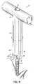
- FIG. 1is a perspective view of a vertebral anchor in the form of a pedicle screw and an associated fastener in the form of a set screw according to one aspect of this invention
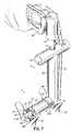
- FIG. 2is a perspective view of the vertebral anchor of FIG. 1 being coupled to an access sleeve according to one aspect of this invention
- FIG. 3is a perspective view of the components of FIG. 2 being coupled to a tool according to another aspect of this invention
- FIG. 4is a perspective view of the components of FIG. 3 being used to screw a first vertebral anchor into a vertebrae of a patient;
- FIG. 5is a perspective view of a connecting element of a dynamic stabilization system being installed on the first vertebral anchor of FIG. 4 ;
- FIG. 6is a perspective view of the components of the dynamic stabilization system being installed relative to a pair of vertebral anchors installed on respective vertebrae of the patient;
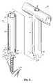
- FIG. 7is a perspective view of the connecting element of the dynamic stabilization system being tensioned between the vertebral anchors and the anchors being distracted during the tensioning process.
- FIGS. 1-2 and 6 - 7depict some of the components of one embodiment of a spinal stabilization system 10 according to this invention.
- vertebral anchors 12are adapted to be installed into adjacent vertebrae 14 , 16 of the spine using removable access members 18 inserted through an incision formed through the patient's skin. The incision may be sized for minimally invasive percutaneous or retractor based techniques or may be used in open procedures.
- at least two anchors 12shown here in the form of pedicle screws, are fixedly installed into the pedicle area of adjacent vertebrae 14 , 16 and a flexible spacer 20 is disposed there between to control motion of the spine, while otherwise leaving the spinal segment mobile.
- the two anchorscan be placed in a patient in combination with a fusion device located between the vertebral bodies.
- the spacer 20 and pedicle screws 12are coupled together by a connecting element 22 which in one embodiment is a flexible member coupled to or passed through the spacer 20 and secured to the heads 24 of the screws 12 .
- a connecting element 22which in one embodiment is a flexible member coupled to or passed through the spacer 20 and secured to the heads 24 of the screws 12 .
- Such spacers 20 and flexible members 22may be similar to those used in the Dynesys® Dynamic Stabilization System available from Zimmer Spine of Minneapolis, Minn.
- the spacer 20may be formed from polycarbonate urethane and the flexible member 22 is a cord that may be formed from polyethylene-terephthalate, although it will be recognized that various other materials suitable for implantation within the human body and for providing stabilization of the spine while maintaining flexibility may be used.
- the anchor 12is a pedicle screw having a threaded shank 26 configured to be screwed into the pedicle area of a vertebra 14 , 16 .
- the head 24 of the screwis configured to receive and secure the flexible member 22 .
- the head 24includes an upwardly open channel 28 formed between upwardly directed arms 30 and extending generally transverse to the longitudinal axis of the shank 26 and having an open end opposite the shank 26 for receiving the flexible member 22 into the channel 28 of the head 24 in a top loading fashion. Accordingly, the channel 28 alleviates the need to thread the flexible member 22 through an eyelet of the head 24 of the anchor 12 after the anchor 12 has been installed into the vertebral body 14 , 16 of a patient's spine.
- the head 24may have a pair of spaced, generally flat face 33 for juxtaposition to the spacer 20 .
- the head 24 of the pedicle screw 12has receiving channels, such as recesses 32 , provided on oppositely disposed sides of the arms 30 of the head 24 to facilitate screwing the anchor 12 into a vertebra 14 , 16 of a patient's spine using a tool as described later herein.
- the pedicle screw 12is formed from a titanium alloy, but it will be recognized that various other materials suitable for implantation within the human body and having sufficient strength to be securely attached to the bone and to secure the flexible member 22 may be used. While a uniaxial pedicle screw is shown and described herein, it will be recognized that the anchor 12 may alternatively comprise a hook, a polyaxial pedicle screw, or various other structure suitable to be secured to a vertebral body.
- An elongate access member 18is removably secured to the head 24 of the pedicle screw 12 and is formed substantially from a resilient, flexible material that permits deformation or bending of the access member 18 along its length without transmitting significant force to the pedicle screw 12 .
- the access member 18may be formed from polymeric material such as nylon, polyethylene, polyurethane, or various other polymeric materials that are biocompatible and provide sufficient flexibility to permit the guides to bend in flexure along their length without transmitting significant force to the pedicle screw 12 .
- the access members 18may be configured as a rigid or a composite structure, comprising a portion formed from a substantially rigid material and a portion comprising a flexible material or wholly of a rigid material.
- the access member 18includes a pair of diametrically opposed, longitudinal slots 34 extending from a first, distal end 36 toward a second, proximal end 38 of the access member 18 .
- Each slot 34has an opening 40 at the first end 36 that is shaped to mate with the head 24 of the pedicle screw 12 such that the slot 34 communicates with the channel 28 formed in the head 24 of the pedicle screw 12 .
- the longitudinally extending slot 34may be used to guide the flexible member 22 from the slots 34 of the access member 18 , along its length, and into the channel 28 formed in the head 24 of the pedicle screw 12 .
- the access member 18includes mating tabs 42 to mate with the receiving channels or recesses 32 on the head 24 of the pedicle screw 12 .
- the mating tabs 42are inwardly direct protrusions.
- Mating surfaces between the pedicle screw and the access member 18are configured to provide a mechanical interlock that is sufficient to withstand forces applied to the access member 18 during installation of the pedicle screws 12 into the vertebrae 14 , 16 and installation of the spacer 20 between adjacent pedicle screws 12 .
- the access members 18may be removed from the heads 24 of the pedicle screws 12 , for example, by application of an appropriate force or by manipulating the access member 18 relative to the pedicle screw 12 , to cause the mating tabs 42 on the access member 18 to dislodge from the recesses 32 on the head 24 of the pedicle screw 12 .
- the access member 18may be formed in a molding process in the form of a sleeve having a longitudinally extending cannula 44 , and may thereafter be joined to the head 24 of the pedicle screw 12 by mechanically interlocking the sleeve 18 onto the head 24 the pedicle screw 12 with the mating tabs 42 and receiving channels like recesses 32 .
- the sleeve 18includes an aperture 48 proximate the second end 38 for receiving various components including a fastener 50 , such as a set screw, for securing the flexible member 22 to the head 24 of the pedicle screw 12 , as will be described more fully below.
- the aperture 48leads to the cannula 44 of the access member 18 to provide percutaneous access to the head 24 of the pedicle screw 12 .
- Threads 52are formed on the inwardly facing surfaces of the arms 30 in the channel 28 of the head 24 .
- the threads 52are sized for engagement with the fastener 50 when it is desired to secure the flexible member 22 to the head 24 of the pedicle screw 12 .
- a driver 54FIG. 7
- other tool suitable for engaging a socket 56 in a top face of the fastener, or set screw, 50may be inserted through the cannula 44 .
- fastener 50has been shown and described herein as comprising a set screw, it will be recognized that various other types of securing members may alternatively be used to secure the flexible member 22 to the head 24 of the anchor 12 .
- the sleeve 18may be configured to accommodate these various other types of fasteners and to percutaneously provide access for them to the anchor 12 .
- the tool 60in one embodiment as shown includes a tubular member 62 extending longitudinally and defines a central cannula 64 extending from a distal end 66 of the tool 60 .
- the tool 60includes a handle 68 at the proximal end 70 of the tubular member 62 and the handle 68 and tubular member 62 in combination form a generally T-shaped configuration according to one embodiment of the tool 60 .
- the T-shaped handle configuration of handle 68can be incorporated into the sleeve 18 .
- the proximal end 70 of the cannula 64 in the tubular member 62is accessed through a port 72 in the handle 68 as shown in FIGS. 3 and 4 .
- the port 72is sized to receive a fastener 50 .
- the handle 68provides a convenient grip for a surgeon to grasp the tool 60 for manipulation during installation of the spinal stabilization system 10 .
- the distal end 66 of the tubular member 62includes a pair of diametrically opposed fingers 74 projecting downwardly.
- Tool receiving channels, such as recesses 76are formed on an inner face of each finger 74 and extends longitudinally toward the body portion of the tubular member 62 .
- the cannula 64 and tubular member 62are sized and configured to fit over the access member 18 and pedicle screw 12 combination as shown in FIG. 3 .
- the recesses 76 at the distal end 66 of the tubular member 62mate with outwardly directed tool mating tabs 78 on the distal end of the access member 18 .
- the tool 60is mated with the vertebral anchor 12 and access member 18 .
- the mating interaction of the mating tabs 42 , 78 and recesses 32 , 76allow the T-shaped tool 60 to drive the pedicle screw 12 as well as act as an anti-torque instrument.
- the surgeonrotates the tool 60 mated with the vertebral anchor 12 and access member 18 to screw the vertebral anchor 12 into the vertebrae 14 , 16 .
- the tool 60can then be uncoupled from the access member 18 by dislodging the tool mating tabs 78 from the recess 76 , thereby leaving the access member 18 mounted on the pedicle screw 12 installed on the vertebrae 14 , 16 .
- FIG. 5the attachment of the connecting member, such as the exemplary flexible member 22 in the form of a flexible cord, to one of the pedicle screws 12 is shown.
- the pedicle screw 12 installed in the vertebrae 14has the access member 18 mounted thereto as shown in FIG. 5 .
- a terminal end 22 a of the connecting element 22is inserted through the slots 34 of the access member 18 and this is likely performed at a portion of the slots 34 and access member 18 extending from the patient's body and above the incision.
- a forceps 80 having a pair of elongate handle members 82 pivotally coupled togethercan be utilized to stabilize and maneuver the flexible member 22 in the access member slots 34 .
- the forceps 80include cooperating jaws 84 , each of which has an arcuate portion 86 and a downwardly depending leg 88 with a notch go proximate the distal end of the leg 88 as shown in FIG. 5 .
- the jaws 84 of the forceps 80surround the access member 18 and the notches go clamp the end 22 a of the flexible member 22 projecting through the slot 34 . Any excess portion of the flexible member 22 that overhangs the notches go may be severed or trimmed as desired.
- the flexible member 22With the flexible member 22 clamped by the forceps 80 and projecting through the slots 34 in the access member 18 as shown in FIG. 5 , the flexible member 22 may be passed through the slots 34 and down to the channel 28 of the pedicle screw 12 .
- the forceps 80 clamped onto the flexible member 22 and around the access member 18may be utilized to push the flexible member 22 from the slots 34 and into the channel 28 .
- the tubular member 62 of the tool 60may be used in combination with the forceps 80 to advance the flexible member 22 from the slots 34 downwardly and into the upwardly open channel 28 of the pedicle screw 12 as shown in FIG. 5 .
- the fastener or set screw 50may be percutaneously introduced through the cannula 44 of the access member 18 for securing the flexible member 22 to the pedicle screw 12 .
- a driver 54 or similar toolmay be utilized to threadably secure the set screw 50 to the head 24 of the pedicle screw 12 thereby securing the flexible member 22 to the pedicle screw 12 .
- the tubular member 62 and T-shaped tool 60may continue to be mounted telescopically on the access member 18 and pedicle screw 12 or removed for easier access and installation of the set screw 50 .
- the adjacent pedicle screw 12 ahas been placed in the associated vertebrae 14 with the procedure as previously described.
- the spacer 20is then put over the flexible member 22 and slid into contact with the head 24 of the first pedicle screw 12 a as shown in FIG. 6 .
- the tool 62can be used to create distraction between the vertebral anchors 12 a , 12 b to allow for easier placement of the spacer 20 between the vertebral anchors 12 a , 12 b .
- a distractive forcecan be generated by the placement of the spacer 20 between the vertebral anchors 12 a , 12 b .
- the spacer 20As the tool 62 shown in FIG. 6 is forced into engagement with the spacer 20 , the spacer 20 then generates a force against the vertebral anchors 12 a , 12 b thus creating distraction of the vertebrae.
- the flexible member 22is then inserted through the slots 34 of the access member 18 on the second pedicle screw 12 b and a connecting element guide tool 92 can be slid over the access member 18 on the second pedicle screw 12 b as shown in FIGS. 6 and 7 .
- the cord guide tool 92is similar to the T-shaped tool 60 previously described in FIGS. 3 and 4 with like reference numerals identifying similar features.
- the flexible member guide tool 92also includes at least one arcuate flange 94 projecting generally perpendicularly from the axis of the tubular member 62 .
- the arcuate flange 94is sized and configured to cradle a portion of the spacer 20 as the tool 92 is pushed downwardly over the access member 18 .
- the arcuate flange 94contacts the end of the spacer 20 adjacent the second pedicle screw 12 b and downward pressure on the tool 92 forces the spacer 20 downwardly and into position between the adjacent pedicle screw heads 24 .
- the arcuate flange 94translates the spacer 20 downward and outward to create distraction by reacting to the force of the flexible member guide tool 92 and pushing against the access member 18 on the second pedicle screw 12 b and the head 24 of the first pedicle screw 12 a .
- the flexible member 22advances from the slots 34 of the access member 18 on the second pedicle screw 12 b and into the channel 28 of the head 24 of the second pedicle screw 12 b.
- this inventionutilizes the tools and spacer to create distraction between the pedicle screw heads 24 and avoids threading the flexible member 22 through an eyelet in the head of the pedicle screw and any over distraction caused by the thickness of the flexible member when pulled into position.
- the flexible member 22may be tensioned utilizing a tensioning tool 96 as shown in FIG. 7 .
- the set screw 50may be passed through the port 70 in the handle 68 of the cord guide tool 92 and seated in the channel 28 of the pedicle screw head 24 .
- the driver 54is then utilized through the cannula 64 of the tool 92 and the access member 18 to mate with the set screw 50 and rotate the set screw 50 into secure engagement in the channel 28 and thereby clamp the tensioned flexible member 22 .
- the driver 54 , cord guide tool 92 , access member 18 and tensioning tool 96may then be removed from the patient and the flexible member 22 trimmed to length.
- the processis repeated on subsequent vertebrae as appropriate and the incision closed to complete the installation.
Landscapes
- Health & Medical Sciences (AREA)
- Orthopedic Medicine & Surgery (AREA)
- Surgery (AREA)
- Life Sciences & Earth Sciences (AREA)
- Neurology (AREA)
- Medical Informatics (AREA)
- Biomedical Technology (AREA)
- Heart & Thoracic Surgery (AREA)
- Engineering & Computer Science (AREA)
- Molecular Biology (AREA)
- Animal Behavior & Ethology (AREA)
- General Health & Medical Sciences (AREA)
- Public Health (AREA)
- Veterinary Medicine (AREA)
- Nuclear Medicine, Radiotherapy & Molecular Imaging (AREA)
- Surgical Instruments (AREA)
Abstract
Description
Claims (15)
Priority Applications (8)
| Application Number | Priority Date | Filing Date | Title |
|---|---|---|---|
| US11/737,151US7922725B2 (en) | 2007-04-19 | 2007-04-19 | Method and associated instrumentation for installation of spinal dynamic stabilization system |
| PCT/US2008/052576WO2008130728A1 (en) | 2007-04-19 | 2008-01-31 | Method and associated instrumentation for installation of spinal dynamic stabilization system |
| EP20080728645EP2152179B1 (en) | 2007-04-19 | 2008-01-31 | Instrumentation for installation of spinal dynamic stabilization system |
| CA002684238ACA2684238A1 (en) | 2007-04-19 | 2008-01-31 | Method and associated instrumentation for installation of spinal dynamic stabilization system |
| AU2008242468AAU2008242468A1 (en) | 2007-04-19 | 2008-01-31 | Method and associated instrumentation for installation of spinal dynamic stabilization system |
| US13/048,447US8632572B2 (en) | 2007-04-19 | 2011-03-15 | Method and associated instrumentation for installation of spinal dynamic stabilization system |
| US14/995,435USRE47377E1 (en) | 2007-04-19 | 2016-01-14 | Method and associated instrumentation for installation of spinal dynamic stabilization system |
| US15/619,948USRE47646E1 (en) | 2007-04-19 | 2017-06-12 | Method and associated instrumentation for installation of spinal dynamic stabilization system |
Applications Claiming Priority (1)
| Application Number | Priority Date | Filing Date | Title |
|---|---|---|---|
| US11/737,151US7922725B2 (en) | 2007-04-19 | 2007-04-19 | Method and associated instrumentation for installation of spinal dynamic stabilization system |
Related Child Applications (1)
| Application Number | Title | Priority Date | Filing Date |
|---|---|---|---|
| US13/048,447ContinuationUS8632572B2 (en) | 2007-04-19 | 2011-03-15 | Method and associated instrumentation for installation of spinal dynamic stabilization system |
Publications (2)
| Publication Number | Publication Date |
|---|---|
| US20080262551A1 US20080262551A1 (en) | 2008-10-23 |
| US7922725B2true US7922725B2 (en) | 2011-04-12 |
Family
ID=39873026
Family Applications (4)
| Application Number | Title | Priority Date | Filing Date |
|---|---|---|---|
| US11/737,151Expired - Fee RelatedUS7922725B2 (en) | 2007-04-19 | 2007-04-19 | Method and associated instrumentation for installation of spinal dynamic stabilization system |
| US13/048,447CeasedUS8632572B2 (en) | 2007-04-19 | 2011-03-15 | Method and associated instrumentation for installation of spinal dynamic stabilization system |
| US14/995,435Active2028-02-27USRE47377E1 (en) | 2007-04-19 | 2016-01-14 | Method and associated instrumentation for installation of spinal dynamic stabilization system |
| US15/619,948Expired - Fee RelatedUSRE47646E1 (en) | 2007-04-19 | 2017-06-12 | Method and associated instrumentation for installation of spinal dynamic stabilization system |
Family Applications After (3)
| Application Number | Title | Priority Date | Filing Date |
|---|---|---|---|
| US13/048,447CeasedUS8632572B2 (en) | 2007-04-19 | 2011-03-15 | Method and associated instrumentation for installation of spinal dynamic stabilization system |
| US14/995,435Active2028-02-27USRE47377E1 (en) | 2007-04-19 | 2016-01-14 | Method and associated instrumentation for installation of spinal dynamic stabilization system |
| US15/619,948Expired - Fee RelatedUSRE47646E1 (en) | 2007-04-19 | 2017-06-12 | Method and associated instrumentation for installation of spinal dynamic stabilization system |
Country Status (5)
| Country | Link |
|---|---|
| US (4) | US7922725B2 (en) |
| EP (1) | EP2152179B1 (en) |
| AU (1) | AU2008242468A1 (en) |
| CA (1) | CA2684238A1 (en) |
| WO (1) | WO2008130728A1 (en) |
Cited By (13)
| Publication number | Priority date | Publication date | Assignee | Title |
|---|---|---|---|---|
| US20130035729A1 (en)* | 2011-08-02 | 2013-02-07 | Blackstone Medical, Inc. | Bayonet counter-torque wrench |
| US20160089186A1 (en)* | 2013-05-13 | 2016-03-31 | Neo Medical Sa | Orthopedic Implant Kit |
| US9439692B1 (en)* | 2015-10-09 | 2016-09-13 | Spine Wave, Inc. | Minimally invasive spinal fixation system and method therefor |
| US9480501B2 (en) | 2013-10-21 | 2016-11-01 | Blackstone Medical, Inc. | Modular pedicle screw |
| US9526529B2 (en) | 2013-09-25 | 2016-12-27 | Blackstone Medical, Inc. | Bone screw systems with pressure caps having biasing members |
| US20170303976A1 (en)* | 2006-08-22 | 2017-10-26 | DePuy Synthes Products, Inc. | Reduction sleeve |
| US20180014856A1 (en)* | 2008-02-05 | 2018-01-18 | Zimmer Spine, Inc. | System and method for insertion of flexible spinal stabilization element |
| US9980758B2 (en) | 2013-11-27 | 2018-05-29 | Blackstone Medical, Inc. | Minimally invasive counter-torque wrench system |
| USRE47377E1 (en) | 2007-04-19 | 2019-05-07 | Zimmer Spine, Inc. | Method and associated instrumentation for installation of spinal dynamic stabilization system |
| US10667845B2 (en)* | 2017-07-19 | 2020-06-02 | Mayo Foundation For Medical Education And Research | Vertebral tethering |
| US10779866B2 (en) | 2016-12-29 | 2020-09-22 | K2M, Inc. | Rod reducer assembly |
| US12127776B2 (en) | 2019-07-02 | 2024-10-29 | Neo Medical Sa | Method, device, and system for preventing lateral stress on bone structures resulting from off-axis forces caused by screw driver and screw extender |
| US12414803B2 (en) | 2019-03-26 | 2025-09-16 | Neo Medical Sa | System for tightening an orthopedic set screw at two different torque levels |
Families Citing this family (84)
| Publication number | Priority date | Publication date | Assignee | Title |
|---|---|---|---|---|
| US7833250B2 (en) | 2004-11-10 | 2010-11-16 | Jackson Roger P | Polyaxial bone screw with helically wound capture connection |
| US10258382B2 (en) | 2007-01-18 | 2019-04-16 | Roger P. Jackson | Rod-cord dynamic connection assemblies with slidable bone anchor attachment members along the cord |
| US10729469B2 (en) | 2006-01-09 | 2020-08-04 | Roger P. Jackson | Flexible spinal stabilization assembly with spacer having off-axis core member |
| US7862587B2 (en) | 2004-02-27 | 2011-01-04 | Jackson Roger P | Dynamic stabilization assemblies, tool set and method |
| US8876868B2 (en) | 2002-09-06 | 2014-11-04 | Roger P. Jackson | Helical guide and advancement flange with radially loaded lip |
| US7621918B2 (en) | 2004-11-23 | 2009-11-24 | Jackson Roger P | Spinal fixation tool set and method |
| US7377923B2 (en) | 2003-05-22 | 2008-05-27 | Alphatec Spine, Inc. | Variable angle spinal screw assembly |
| US8366753B2 (en) | 2003-06-18 | 2013-02-05 | Jackson Roger P | Polyaxial bone screw assembly with fixed retaining structure |
| US7967850B2 (en) | 2003-06-18 | 2011-06-28 | Jackson Roger P | Polyaxial bone anchor with helical capture connection, insert and dual locking assembly |
| US8926670B2 (en) | 2003-06-18 | 2015-01-06 | Roger P. Jackson | Polyaxial bone screw assembly |
| US7766915B2 (en) | 2004-02-27 | 2010-08-03 | Jackson Roger P | Dynamic fixation assemblies with inner core and outer coil-like member |
| US7776067B2 (en) | 2005-05-27 | 2010-08-17 | Jackson Roger P | Polyaxial bone screw with shank articulation pressure insert and method |
| US7179261B2 (en) | 2003-12-16 | 2007-02-20 | Depuy Spine, Inc. | Percutaneous access devices and bone anchor assemblies |
| US7527638B2 (en) | 2003-12-16 | 2009-05-05 | Depuy Spine, Inc. | Methods and devices for minimally invasive spinal fixation element placement |
| US11419642B2 (en) | 2003-12-16 | 2022-08-23 | Medos International Sarl | Percutaneous access devices and bone anchor assemblies |
| US8152810B2 (en) | 2004-11-23 | 2012-04-10 | Jackson Roger P | Spinal fixation tool set and method |
| US11241261B2 (en) | 2005-09-30 | 2022-02-08 | Roger P Jackson | Apparatus and method for soft spinal stabilization using a tensionable cord and releasable end structure |
| JP2007525274A (en) | 2004-02-27 | 2007-09-06 | ロジャー・ピー・ジャクソン | Orthopedic implant rod reduction instrument set and method |
| US7160300B2 (en) | 2004-02-27 | 2007-01-09 | Jackson Roger P | Orthopedic implant rod reduction tool set and method |
| US7651502B2 (en) | 2004-09-24 | 2010-01-26 | Jackson Roger P | Spinal fixation tool set and method for rod reduction and fastener insertion |
| US8926672B2 (en) | 2004-11-10 | 2015-01-06 | Roger P. Jackson | Splay control closure for open bone anchor |
| US8444681B2 (en) | 2009-06-15 | 2013-05-21 | Roger P. Jackson | Polyaxial bone anchor with pop-on shank, friction fit retainer and winged insert |
| US9168069B2 (en) | 2009-06-15 | 2015-10-27 | Roger P. Jackson | Polyaxial bone anchor with pop-on shank and winged insert with lower skirt for engaging a friction fit retainer |
| WO2006057837A1 (en) | 2004-11-23 | 2006-06-01 | Jackson Roger P | Spinal fixation tool attachment structure |
| US7901437B2 (en) | 2007-01-26 | 2011-03-08 | Jackson Roger P | Dynamic stabilization member with molded connection |
| WO2007038429A1 (en) | 2005-09-27 | 2007-04-05 | Endius, Inc. | Methods and apparatuses for stabilizing the spine through an access device |
| US8100946B2 (en) | 2005-11-21 | 2012-01-24 | Synthes Usa, Llc | Polyaxial bone anchors with increased angulation |
| US8034078B2 (en) | 2008-05-30 | 2011-10-11 | Globus Medical, Inc. | System and method for replacement of spinal motion segment |
| US7947045B2 (en)* | 2006-10-06 | 2011-05-24 | Zimmer Spine, Inc. | Spinal stabilization system with flexible guides |
| CA2670988C (en) | 2006-12-08 | 2014-03-25 | Roger P. Jackson | Tool system for dynamic spinal implants |
| US11224463B2 (en) | 2007-01-18 | 2022-01-18 | Roger P. Jackson | Dynamic stabilization connecting member with pre-tensioned flexible core member |
| US8475498B2 (en) | 2007-01-18 | 2013-07-02 | Roger P. Jackson | Dynamic stabilization connecting member with cord connection |
| WO2008134703A2 (en)* | 2007-04-30 | 2008-11-06 | Globus Medical, Inc. | Flexible spine stabilization system |
| US10383660B2 (en)* | 2007-05-01 | 2019-08-20 | Roger P. Jackson | Soft stabilization assemblies with pretensioned cords |
| US8979904B2 (en) | 2007-05-01 | 2015-03-17 | Roger P Jackson | Connecting member with tensioned cord, low profile rigid sleeve and spacer with torsion control |
| US9439681B2 (en) | 2007-07-20 | 2016-09-13 | DePuy Synthes Products, Inc. | Polyaxial bone fixation element |
| US8323294B2 (en)* | 2007-08-21 | 2012-12-04 | Depuy Spine, Inc. | Tether tensioning instrument |
| USD620109S1 (en) | 2008-02-05 | 2010-07-20 | Zimmer Spine, Inc. | Surgical installation tool |
| CA2713982C (en)* | 2008-02-07 | 2016-05-03 | Synthes Usa, Llc | Pelvic cable solution |
| AU2010260521C1 (en) | 2008-08-01 | 2013-08-01 | Roger P. Jackson | Longitudinal connecting member with sleeved tensioned cords |
| EP2484300B1 (en)* | 2008-09-05 | 2015-05-20 | Biedermann Technologies GmbH & Co. KG | Stabilization device for bones, in particular for the spinal column |
| JP5815407B2 (en) | 2008-09-12 | 2015-11-17 | ジンテス ゲゼルシャフト ミット ベシュレンクテル ハフツング | Spinal stabilization and guided fixation system |
| KR20110081208A (en) | 2008-09-29 | 2011-07-13 | 신세스 게엠바하 | Multi-Axis Bottom-Loading Screw and Rod Assemblies |
| CA2742399A1 (en) | 2008-11-03 | 2010-06-03 | Dustin M. Harvey | Uni-planar bone fixation assembly |
| US20100137908A1 (en)* | 2008-12-01 | 2010-06-03 | Zimmer Spine, Inc. | Dynamic Stabilization System Components Including Readily Visualized Polymeric Compositions |
| US9055979B2 (en)* | 2008-12-03 | 2015-06-16 | Zimmer Gmbh | Cord for vertebral fixation having multiple stiffness phases |
| US8137355B2 (en) | 2008-12-12 | 2012-03-20 | Zimmer Spine, Inc. | Spinal stabilization installation instrumentation and methods |
| IT1392200B1 (en)* | 2008-12-17 | 2012-02-22 | N B R New Biotechnology Res | MODULAR VERTEBRAL STABILIZER. |
| US8137356B2 (en)* | 2008-12-29 | 2012-03-20 | Zimmer Spine, Inc. | Flexible guide for insertion of a vertebral stabilization system |
| EP2233097B1 (en)* | 2009-03-26 | 2012-02-08 | Spinelab AG | Instrument set for inserting a stabilisation system into the spine of a body |
| KR20120013312A (en) | 2009-04-15 | 2012-02-14 | 신세스 게엠바하 | Orthodontic Connectors for Spinal Structures |
| US9668771B2 (en) | 2009-06-15 | 2017-06-06 | Roger P Jackson | Soft stabilization assemblies with off-set connector |
| US8998959B2 (en) | 2009-06-15 | 2015-04-07 | Roger P Jackson | Polyaxial bone anchors with pop-on shank, fully constrained friction fit retainer and lock and release insert |
| US11229457B2 (en) | 2009-06-15 | 2022-01-25 | Roger P. Jackson | Pivotal bone anchor assembly with insert tool deployment |
| CN103826560A (en) | 2009-06-15 | 2014-05-28 | 罗杰.P.杰克逊 | Polyaxial Bone Anchor with Socket Stem and Winged Inserts with Friction Fit Compression Collars |
| CA2764841A1 (en) | 2009-06-17 | 2010-12-23 | Synthes Usa, Llc | Revision connector for spinal constructs |
| US9211144B2 (en)* | 2009-09-09 | 2015-12-15 | Globus Medical, Inc. | Spine surgery device and method |
| US8328849B2 (en) | 2009-12-01 | 2012-12-11 | Zimmer Gmbh | Cord for vertebral stabilization system |
| US8740945B2 (en)* | 2010-04-07 | 2014-06-03 | Zimmer Spine, Inc. | Dynamic stabilization system using polyaxial screws |
| US8206395B2 (en)* | 2010-06-18 | 2012-06-26 | Spine Wave, Inc. | Surgical instrument and method for the distraction or compression of bones |
| US8777954B2 (en)* | 2010-06-18 | 2014-07-15 | Spine Wave, Inc. | Pedicle screw extension for use in percutaneous spinal fixation |
| US20120046698A1 (en)* | 2010-08-18 | 2012-02-23 | Doctors Research Group, Inc. | Methods and devices for spinal fusion |
| US8382803B2 (en) | 2010-08-30 | 2013-02-26 | Zimmer Gmbh | Vertebral stabilization transition connector |
| AU2011299558A1 (en) | 2010-09-08 | 2013-05-02 | Roger P. Jackson | Dynamic stabilization members with elastic and inelastic sections |
| US9044274B2 (en) | 2010-12-01 | 2015-06-02 | Amendia, Inc. | Bone screw system |
| FR2976784B1 (en)* | 2011-06-23 | 2013-07-05 | Spineway | SURGICAL DEVICE FOR THE CORRECTION OF DEFORMATION OF THE VERTEBRAL COLUMN |
| WO2013040456A1 (en)* | 2011-09-14 | 2013-03-21 | Band-Lok, Llc | Tether clamp and implantation system |
| US8911479B2 (en) | 2012-01-10 | 2014-12-16 | Roger P. Jackson | Multi-start closures for open implants |
| US8911478B2 (en) | 2012-11-21 | 2014-12-16 | Roger P. Jackson | Splay control closure for open bone anchor |
| US10058354B2 (en) | 2013-01-28 | 2018-08-28 | Roger P. Jackson | Pivotal bone anchor assembly with frictional shank head seating surfaces |
| US8852239B2 (en) | 2013-02-15 | 2014-10-07 | Roger P Jackson | Sagittal angle screw with integral shank and receiver |
| US9566092B2 (en) | 2013-10-29 | 2017-02-14 | Roger P. Jackson | Cervical bone anchor with collet retainer and outer locking sleeve |
| US9717533B2 (en) | 2013-12-12 | 2017-08-01 | Roger P. Jackson | Bone anchor closure pivot-splay control flange form guide and advancement structure |
| US9451993B2 (en) | 2014-01-09 | 2016-09-27 | Roger P. Jackson | Bi-radial pop-on cervical bone anchor |
| US9597119B2 (en) | 2014-06-04 | 2017-03-21 | Roger P. Jackson | Polyaxial bone anchor with polymer sleeve |
| US10064658B2 (en) | 2014-06-04 | 2018-09-04 | Roger P. Jackson | Polyaxial bone anchor with insert guides |
| FR3026636B1 (en)* | 2014-10-01 | 2017-09-15 | Cousin Biotech | ANCHORAGE FOR TENSIONING A LONGILINE ELEMENT FOR ATTACHING AN IMPLANT TO A BONE MEMBER |
| WO2016172677A1 (en)* | 2015-04-24 | 2016-10-27 | K2M, Inc. | Tethering screw system |
| EP3490474A4 (en) | 2016-07-26 | 2019-08-28 | Band-lok, LLC | ORTHOPEDIC IMPLANTS. |
| US10307186B2 (en)* | 2016-12-02 | 2019-06-04 | Nuvasive, Inc. | Surgical band clamp system |
| US10939941B2 (en) | 2017-08-29 | 2021-03-09 | Zimmer Biomet Spine, Inc. | Surgical cord tensioning devices, systems, and methods |
| CA3073564C (en)* | 2017-08-29 | 2022-10-18 | Zimmer Biomet Spine, Inc. | Surgical cord tensioning devices, systems, and methods |
| US11020149B2 (en)* | 2018-02-28 | 2021-06-01 | Globus Medical Inc. | Scoliosis correction systems, methods, and instruments |
| FR3097114B1 (en)* | 2019-06-13 | 2024-05-31 | Medicrea Int | Additional fixation device for a pedicle screw on a spinal bone segment |
Citations (92)
| Publication number | Priority date | Publication date | Assignee | Title |
|---|---|---|---|---|
| US2248054A (en) | 1939-06-07 | 1941-07-08 | Becker Joseph | Screw driver |
| NL7610576A (en) | 1976-09-23 | 1978-03-29 | Gerard Hendrik Slot | Spinal column repositioning system - uses tongs to position screws in column sections before securing to rope |
| US4526067A (en) | 1982-02-17 | 1985-07-02 | Societe Nationale Industrielle Et Aerospatiale | Automatic mounting appliance for assembling means |
| US4862774A (en) | 1987-02-24 | 1989-09-05 | Else Frederick A | Screw holder |
| US4946458A (en) | 1986-04-25 | 1990-08-07 | Harms Juergen | Pedicle screw |
| US5030220A (en) | 1990-03-29 | 1991-07-09 | Advanced Spine Fixation Systems Incorporated | Spine fixation system |
| US5261913A (en) | 1989-07-26 | 1993-11-16 | J.B.S. Limited Company | Device for straightening, securing, compressing and elongating the spinal column |
| WO1994017745A1 (en) | 1993-02-09 | 1994-08-18 | Plus Endoprothetik Ag | Device for stiffening and/or correcting the spine |
| US5360431A (en) | 1990-04-26 | 1994-11-01 | Cross Medical Products | Transpedicular screw system and method of use |
| WO1995019149A1 (en) | 1994-01-18 | 1995-07-20 | Safir S.A.R.L. | Global vertebral fixation device |
| EP0669109A1 (en) | 1994-02-28 | 1995-08-30 | SULZER Medizinaltechnik AG | Stabilizer for adjacent vertebrae |
| US5458030A (en) | 1992-11-04 | 1995-10-17 | Betts; Geoffrey | Screwdrivers |
| US5540688A (en) | 1991-05-30 | 1996-07-30 | Societe "Psi" | Intervertebral stabilization device incorporating dampers |
| US5584831A (en) | 1993-07-09 | 1996-12-17 | September 28, Inc. | Spinal fixation device and method |
| US5672176A (en) | 1995-03-15 | 1997-09-30 | Biedermann; Lutz | Anchoring member |
| US5681319A (en) | 1995-03-01 | 1997-10-28 | Biedermann; Lutz | Locking tool |
| WO1999005980A1 (en) | 1997-07-31 | 1999-02-11 | Plus Endoprothetik Ag | Device for stiffening and/or correcting a vertebral column or such like |
| US5989254A (en) | 1997-05-20 | 1999-11-23 | Katz; Akiva Raphael | Pedicle screw assembly |
| US6112623A (en) | 1997-05-30 | 2000-09-05 | Sofamor S.N.C. | Tool for screwing a screw having two threaded portions separated by an intermediate screwing portion |
| US6139549A (en) | 1996-04-09 | 2000-10-31 | Waldemar Link (Gmbh & Co.) | Spinal fixing device |
| WO2001001873A1 (en) | 1999-07-01 | 2001-01-11 | Spinevision S.A. | Fixing element and ancillary for stabilising vertebrae |
| US6183472B1 (en) | 1998-04-09 | 2001-02-06 | Howmedica Gmbh | Pedicle screw and an assembly aid therefor |
| US20010007074A1 (en) | 1999-12-23 | 2001-07-05 | Michael Strobel | Screw for medical purposes and a driving tool |
| US20010012937A1 (en) | 2000-02-07 | 2001-08-09 | Ulrich Gmbh & Co. Kg | Polyaxial pedicle screw |
| US20020035366A1 (en) | 2000-09-18 | 2002-03-21 | Reto Walder | Pedicle screw for intervertebral support elements |
| US20020058942A1 (en) | 2000-11-10 | 2002-05-16 | Biedermann Motech Gmbh | Bone screw |
| US20020082602A1 (en) | 2000-12-22 | 2002-06-27 | Lutz Biedermann | Fixing element |
| US20020116001A1 (en) | 2001-02-17 | 2002-08-22 | Bernd Schafer | Bone screw |
| WO2002069854A1 (en) | 2001-03-06 | 2002-09-12 | Sung-Kon Kim | Screw for fixing spine |
| US20020133159A1 (en) | 2000-12-08 | 2002-09-19 | Jackson Roger P. | Closure for open-headed medical implant |
| US20020133154A1 (en) | 2001-03-15 | 2002-09-19 | Saint Martin Pierre Henri | Anchoring member with safety ring |
| US20020138076A1 (en) | 2000-12-27 | 2002-09-26 | Biederman Motech Gmbh | Screw |
| US20020143341A1 (en) | 2001-03-27 | 2002-10-03 | Lutz Biedermann | Anchoring element |
| US6471705B1 (en) | 1999-08-02 | 2002-10-29 | Lutz Biedermann | Bone screw |
| US20030018342A1 (en) | 2000-03-28 | 2003-01-23 | Showa Ika Kohgyo Co., Ltd. | Spinal implant, driver tool and nut guide |
| US20030023243A1 (en) | 2001-07-27 | 2003-01-30 | Biedermann Motech Gmbh | Bone screw and fastening tool for same |
| US6530929B1 (en) | 1999-10-20 | 2003-03-11 | Sdgi Holdings, Inc. | Instruments for stabilization of bony structures |
| US20030100896A1 (en) | 2001-11-27 | 2003-05-29 | Lutz Biedermann | Element with a shank and a holding element connected to it for connecting to a rod |
| US20030100904A1 (en) | 2001-11-27 | 2003-05-29 | Lutz Biedermann | Locking device for securing a rod-shaped element in a holding element connected to a shank |
| US20030114860A1 (en) | 1999-12-03 | 2003-06-19 | Remi Cavagna | Tighening instrument for orthopaedic surgery of the spine |
| US20030125741A1 (en) | 2001-12-28 | 2003-07-03 | Biedermann Motech Gmbh | Locking device for securing a rod-shaped element in a holding element connected to a shank |
| US20030187439A1 (en) | 2002-03-27 | 2003-10-02 | Biedermann Motech Gmbh | Bone anchoring device for stabilizing bone segments and seat part of a bone anchoring device |
| WO2004004549A2 (en) | 2002-07-10 | 2004-01-15 | Joseph Aferzon | Spinal support coupling device |
| FR2844180A1 (en) | 2002-09-11 | 2004-03-12 | Spinevision | Connection element for spinal fixation system designed to link at least two implantable connection assemblies, is formed from a helicoidal spring part and a polymeric material support part |
| US20040097933A1 (en) | 2002-11-19 | 2004-05-20 | Rodolphe Lourdel | Vertebral anchoring device and its blocking device on a polyaxial screw |
| WO2004041100A1 (en) | 2002-10-30 | 2004-05-21 | Spinal Concepts, Inc. | Spinal stabilization system insertion and methods |
| US20040102781A1 (en) | 2002-11-25 | 2004-05-27 | U & I Corporation | Bone fixation apparatus, method and tool for assembling the same |
| US20040122425A1 (en) | 2002-09-12 | 2004-06-24 | Showa Ika Kohgyo Co., Ltd. | Rod fixing apparatus for vertebra connecting member |
| US20040176766A1 (en) | 2002-02-13 | 2004-09-09 | Shluzas Alan E. | Apparatus for connecting a longitudinal member to a bone portion |
| US20040181224A1 (en) | 2003-03-11 | 2004-09-16 | Biedermann Motech Gmbh | Anchoring element for use in spine or bone surgery, methods for use and production thereof |
| US20040186474A1 (en) | 2002-12-02 | 2004-09-23 | Biedermann Motech Gmbh | Implant having a shaft and a holding element connected therewith for connecting with a rod |
| US20040225289A1 (en) | 2003-05-07 | 2004-11-11 | Biedermann Motech Gmbh | Dynamic anchoring device and dynamic stabilization device for bones, in particular for vertebrae, with such an anchoring device |
| US20040243193A1 (en) | 2003-05-30 | 2004-12-02 | Ballis Joseph J. | Electromagnetic interference alarm |
| US20040249378A1 (en) | 2001-10-04 | 2004-12-09 | Saint Martin Pierre Henri | Spinal osteosynthesis assembly comprising the head of an anchoring member and a tool for fixing said head |
| US20050010220A1 (en) | 2003-04-24 | 2005-01-13 | Simon Casutt | Instrument system for pedicle screws |
| US20050055026A1 (en) | 2002-10-02 | 2005-03-10 | Biedermann Motech Gmbh | Bone anchoring element |
| US20050065516A1 (en) | 2003-09-24 | 2005-03-24 | Tae-Ahn Jahng | Method and apparatus for flexible fixation of a spine |
| US20050065526A1 (en) | 2001-12-04 | 2005-03-24 | Tim Drew | Fixing device and applicator therefor |
| EP1523949A1 (en) | 2003-10-17 | 2005-04-20 | BIEDERMANN MOTECH GmbH | Surgical rod element, stabilisation device, and method of manufacturing the element |
| US6896677B1 (en) | 2003-12-11 | 2005-05-24 | A-Spine Holding Group Corp. | Rotary device for retrieving spinal column under treatment |
| US20050124991A1 (en) | 2003-12-05 | 2005-06-09 | Tae-Ahn Jahng | Method and apparatus for flexible fixation of a spine |
| US6905500B2 (en) | 2001-10-31 | 2005-06-14 | U & I Corporation | Bone fixation apparatus |
| US20050131421A1 (en) | 2003-12-16 | 2005-06-16 | Anderson David G. | Methods and devices for minimally invasive spinal fixation element placement |
| US20050131408A1 (en) | 2003-12-16 | 2005-06-16 | Sicvol Christopher W. | Percutaneous access devices and bone anchor assemblies |
| US20050143737A1 (en) | 2003-12-31 | 2005-06-30 | John Pafford | Dynamic spinal stabilization system |
| US20050154390A1 (en) | 2003-11-07 | 2005-07-14 | Lutz Biedermann | Stabilization device for bones comprising a spring element and manufacturing method for said spring element |
| US20050192579A1 (en) | 2004-02-27 | 2005-09-01 | Jackson Roger P. | Orthopedic implant rod reduction tool set and method |
| FR2867057A1 (en) | 2004-03-02 | 2005-09-09 | Spinevision | Connecting element, useful for a spinal fixing system to connect two entire implantable connection bodies comprises a cable and a polymer envelope surrounding the cable |
| US20050203513A1 (en) | 2003-09-24 | 2005-09-15 | Tae-Ahn Jahng | Spinal stabilization device |
| US20050234451A1 (en) | 2004-04-16 | 2005-10-20 | Markworth Aaron D | Pedicle screw assembly |
| US20050267472A1 (en) | 2002-03-27 | 2005-12-01 | Biedermann Motech Gmbh | Bone anchoring device for stabilising bone segments and seat part of a bone anchoring device |
| US6986771B2 (en) | 2003-05-23 | 2006-01-17 | Globus Medical, Inc. | Spine stabilization system |
| US6994710B2 (en) | 2001-05-09 | 2006-02-07 | Patrick Michel White | Surgical driver |
| US7008424B2 (en) | 2000-06-23 | 2006-03-07 | University Of Southern California | Percutaneous vertebral fusion system |
| US20060111715A1 (en) | 2004-02-27 | 2006-05-25 | Jackson Roger P | Dynamic stabilization assemblies, tool set and method |
| US20060111712A1 (en) | 2004-11-23 | 2006-05-25 | Jackson Roger P | Spinal fixation tool set and method |
| WO2006066685A1 (en) | 2004-12-17 | 2006-06-29 | Zimmer Gmbh | Intervertebral stabilisation system |
| US20060155277A1 (en) | 2002-03-21 | 2006-07-13 | Peter Metz-Stavenhagen | Anchoring element for securing a rod of a device for adjusting a human or animal vertrebal column on a vertreba |
| US7081116B1 (en) | 1999-06-14 | 2006-07-25 | Scient'x | Implant for osteosynthesis device in particular of the backbone |
| US20060217738A1 (en) | 2003-04-16 | 2006-09-28 | Remy Tanimura | Method for reversible fixing of a tool to an implantable element and device for carrying out such a fixing method |
| US20060230887A1 (en) | 2003-06-25 | 2006-10-19 | Yasuaki Taguchi | Bit holder device |
| US20070016200A1 (en) | 2003-04-09 | 2007-01-18 | Jackson Roger P | Dynamic stabilization medical implant assemblies and methods |
| US20070055244A1 (en) | 2004-02-27 | 2007-03-08 | Jackson Roger P | Dynamic fixation assemblies with inner core and outer coil-like member |
| US20070078461A1 (en) | 2005-09-27 | 2007-04-05 | Shluzas Alan E | Methods and apparatuses for stabilizing the spine through an access device |
| US20070198088A1 (en) | 2003-10-17 | 2007-08-23 | Lutz Biedermann | Flexible implant |
| US20070270860A1 (en) | 2005-09-30 | 2007-11-22 | Jackson Roger P | Dynamic stabilization connecting member with slitted core and outer sleeve |
| US20070293862A1 (en) | 2005-09-30 | 2007-12-20 | Jackson Roger P | Dynamic stabilization connecting member with elastic core and outer sleeve |
| US20080091213A1 (en) | 2004-02-27 | 2008-04-17 | Jackson Roger P | Tool system for dynamic spinal implants |
| US20080140076A1 (en) | 2005-09-30 | 2008-06-12 | Jackson Roger P | Dynamic stabilization connecting member with slitted segment and surrounding external elastomer |
| US20080147122A1 (en) | 2006-10-12 | 2008-06-19 | Jackson Roger P | Dynamic stabilization connecting member with molded inner segment and surrounding external elastomer |
| US20080177317A1 (en) | 2007-01-18 | 2008-07-24 | Jackson Roger P | Dynamic stabilization connecting member with cord connection |
| US20080183216A1 (en) | 2007-01-26 | 2008-07-31 | Jackson Roger P | Dynamic stabilization member with molded connection |
Family Cites Families (25)
| Publication number | Priority date | Publication date | Assignee | Title |
|---|---|---|---|---|
| DE3800052A1 (en) | 1987-07-08 | 1989-07-13 | Harms Juergen | POSITIONING SCREW |
| DE3823737A1 (en) | 1988-07-13 | 1990-01-18 | Lutz Biedermann | CORRECTION AND HOLDING DEVICE, ESPECIALLY FOR THE SPINE |
| DE3936702C2 (en) | 1989-11-03 | 1994-07-28 | Lutz Biedermann | Pedicle screw and correction and holding device with such a pedicle screw |
| GB9110778D0 (en) | 1991-05-18 | 1991-07-10 | Middleton Jeffrey K | Apparatus for use in surgery |
| FR2684866B1 (en) | 1991-12-12 | 1994-05-13 | Jbs | IMPROVEMENTS IN METHODS AND DEVICES FOR STRAIGHTENING, FIXING, COMPRESSION, ELONGATION OF THE RACHIS. |
| DE4243951C2 (en) | 1992-12-23 | 1997-07-03 | Plus Endoprothetik Ag | Device for stiffening a spinal column section consisting of at least two vertebrae |
| DE59310397D1 (en) | 1993-07-02 | 2009-07-09 | Synthes Gmbh | Posterior spine implant |
| AU1181495A (en) | 1993-11-19 | 1995-06-06 | Cross Medical Products, Inc. | Spine rod anchors, spine rod connectors and nut alignment guide |
| WO1995013755A1 (en) | 1993-11-19 | 1995-05-26 | Cross Medical Products, Inc. | Rod anchor seat having sliding closure member |
| WO1995014437A1 (en) | 1993-11-25 | 1995-06-01 | Sofamor Danek Group, Inc. | Implant for an osteosynthesis device, particularly for the spine, and positioning instrument therefor |
| US5879350A (en) | 1996-09-24 | 1999-03-09 | Sdgi Holdings, Inc. | Multi-axial bone screw assembly |
| US5964769A (en)* | 1997-08-26 | 1999-10-12 | Spinal Concepts, Inc. | Surgical cable system and method |
| US6296642B1 (en) | 1998-11-09 | 2001-10-02 | Sdgi Holdings, Inc. | Reverse angle thread for preventing splaying in medical devices |
| DE50007759D1 (en)* | 1999-11-25 | 2004-10-21 | Sulzer Orthopedics Ltd | Surgical instrument for tensioning a cable-like tensioning element |
| US7621918B2 (en)* | 2004-11-23 | 2009-11-24 | Jackson Roger P | Spinal fixation tool set and method |
| US7476240B2 (en) | 2004-02-06 | 2009-01-13 | Depuy Spine, Inc. | Devices and methods for inserting a spinal fixation element |
| US7160300B2 (en)* | 2004-02-27 | 2007-01-09 | Jackson Roger P | Orthopedic implant rod reduction tool set and method |
| US7465306B2 (en)* | 2004-08-13 | 2008-12-16 | Warsaw Orthopedic, Inc. | System and method for positioning a connecting member adjacent the spinal column in minimally invasive procedures |
| US7951175B2 (en)* | 2005-03-04 | 2011-05-31 | Depuy Spine, Inc. | Instruments and methods for manipulating a vertebra |
| US7927360B2 (en) | 2006-01-26 | 2011-04-19 | Warsaw Orthopedic, Inc. | Spinal anchor assemblies having extended receivers |
| WO2007121271A2 (en) | 2006-04-11 | 2007-10-25 | Synthes (U.S.A) | Minimally invasive fixation system |
| US20080009863A1 (en)* | 2006-06-23 | 2008-01-10 | Zimmer Spine, Inc. | Pedicle screw distractor and associated method of use |
| US9526525B2 (en)* | 2006-08-22 | 2016-12-27 | Neuropro Technologies, Inc. | Percutaneous system for dynamic spinal stabilization |
| US7918857B2 (en) | 2006-09-26 | 2011-04-05 | Depuy Spine, Inc. | Minimally invasive bone anchor extensions |
| US7922725B2 (en) | 2007-04-19 | 2011-04-12 | Zimmer Spine, Inc. | Method and associated instrumentation for installation of spinal dynamic stabilization system |
- 2007
- 2007-04-19USUS11/737,151patent/US7922725B2/ennot_activeExpired - Fee Related
- 2008
- 2008-01-31WOPCT/US2008/052576patent/WO2008130728A1/enactiveApplication Filing
- 2008-01-31EPEP20080728645patent/EP2152179B1/ennot_activeNot-in-force
- 2008-01-31CACA002684238Apatent/CA2684238A1/ennot_activeAbandoned
- 2008-01-31AUAU2008242468Apatent/AU2008242468A1/ennot_activeAbandoned
- 2011
- 2011-03-15USUS13/048,447patent/US8632572B2/ennot_activeCeased
- 2016
- 2016-01-14USUS14/995,435patent/USRE47377E1/enactiveActive
- 2017
- 2017-06-12USUS15/619,948patent/USRE47646E1/ennot_activeExpired - Fee Related
Patent Citations (125)
| Publication number | Priority date | Publication date | Assignee | Title |
|---|---|---|---|---|
| US2248054A (en) | 1939-06-07 | 1941-07-08 | Becker Joseph | Screw driver |
| NL7610576A (en) | 1976-09-23 | 1978-03-29 | Gerard Hendrik Slot | Spinal column repositioning system - uses tongs to position screws in column sections before securing to rope |
| US4526067A (en) | 1982-02-17 | 1985-07-02 | Societe Nationale Industrielle Et Aerospatiale | Automatic mounting appliance for assembling means |
| US4946458A (en) | 1986-04-25 | 1990-08-07 | Harms Juergen | Pedicle screw |
| US4862774A (en) | 1987-02-24 | 1989-09-05 | Else Frederick A | Screw holder |
| US5261913A (en) | 1989-07-26 | 1993-11-16 | J.B.S. Limited Company | Device for straightening, securing, compressing and elongating the spinal column |
| US5030220A (en) | 1990-03-29 | 1991-07-09 | Advanced Spine Fixation Systems Incorporated | Spine fixation system |
| US5360431A (en) | 1990-04-26 | 1994-11-01 | Cross Medical Products | Transpedicular screw system and method of use |
| US5540688A (en) | 1991-05-30 | 1996-07-30 | Societe "Psi" | Intervertebral stabilization device incorporating dampers |
| US5458030A (en) | 1992-11-04 | 1995-10-17 | Betts; Geoffrey | Screwdrivers |
| WO1994017745A1 (en) | 1993-02-09 | 1994-08-18 | Plus Endoprothetik Ag | Device for stiffening and/or correcting the spine |
| US5562660A (en) | 1993-02-09 | 1996-10-08 | Plus Endoprothetik Ag | Apparatus for stiffening and/or correcting the vertebral column |
| US5584831A (en) | 1993-07-09 | 1996-12-17 | September 28, Inc. | Spinal fixation device and method |
| WO1995019149A1 (en) | 1994-01-18 | 1995-07-20 | Safir S.A.R.L. | Global vertebral fixation device |
| FR2715057A1 (en) | 1994-01-18 | 1995-07-21 | Breard Francis Henri | Overall device for stabilizing the spine. |
| EP0669109B1 (en) | 1994-02-28 | 1999-05-26 | Sulzer Orthopädie AG | Stabilizer for adjacent vertebrae |
| EP0669109A1 (en) | 1994-02-28 | 1995-08-30 | SULZER Medizinaltechnik AG | Stabilizer for adjacent vertebrae |
| US5681319A (en) | 1995-03-01 | 1997-10-28 | Biedermann; Lutz | Locking tool |
| US5672176A (en) | 1995-03-15 | 1997-09-30 | Biedermann; Lutz | Anchoring member |
| US6139549A (en) | 1996-04-09 | 2000-10-31 | Waldemar Link (Gmbh & Co.) | Spinal fixing device |
| US5989254A (en) | 1997-05-20 | 1999-11-23 | Katz; Akiva Raphael | Pedicle screw assembly |
| US6112623A (en) | 1997-05-30 | 2000-09-05 | Sofamor S.N.C. | Tool for screwing a screw having two threaded portions separated by an intermediate screwing portion |
| WO1999005980A1 (en) | 1997-07-31 | 1999-02-11 | Plus Endoprothetik Ag | Device for stiffening and/or correcting a vertebral column or such like |
| US6290700B1 (en) | 1997-07-31 | 2001-09-18 | Plus Endoprothetik Ag | Device for stiffening and/or correcting a vertebral column or such like |
| US6183472B1 (en) | 1998-04-09 | 2001-02-06 | Howmedica Gmbh | Pedicle screw and an assembly aid therefor |
| US7081116B1 (en) | 1999-06-14 | 2006-07-25 | Scient'x | Implant for osteosynthesis device in particular of the backbone |
| WO2001001873A1 (en) | 1999-07-01 | 2001-01-11 | Spinevision S.A. | Fixing element and ancillary for stabilising vertebrae |
| US6471705B1 (en) | 1999-08-02 | 2002-10-29 | Lutz Biedermann | Bone screw |
| US6530929B1 (en) | 1999-10-20 | 2003-03-11 | Sdgi Holdings, Inc. | Instruments for stabilization of bony structures |
| US20030114860A1 (en) | 1999-12-03 | 2003-06-19 | Remi Cavagna | Tighening instrument for orthopaedic surgery of the spine |
| US20010007074A1 (en) | 1999-12-23 | 2001-07-05 | Michael Strobel | Screw for medical purposes and a driving tool |
| US6402752B2 (en) | 2000-02-07 | 2002-06-11 | Ulrich Gmbh & Co. Kg | Polyaxial pedicle-screw |
| US20010012937A1 (en) | 2000-02-07 | 2001-08-09 | Ulrich Gmbh & Co. Kg | Polyaxial pedicle screw |
| US20030018342A1 (en) | 2000-03-28 | 2003-01-23 | Showa Ika Kohgyo Co., Ltd. | Spinal implant, driver tool and nut guide |
| US6932822B2 (en) | 2000-03-28 | 2005-08-23 | Showa Ika Kohgyo Co., Ltd. | Spinal implant, driver tool and nut guide |
| US7008424B2 (en) | 2000-06-23 | 2006-03-07 | University Of Southern California | Percutaneous vertebral fusion system |
| US20020035366A1 (en) | 2000-09-18 | 2002-03-21 | Reto Walder | Pedicle screw for intervertebral support elements |
| US20060084995A1 (en) | 2000-11-10 | 2006-04-20 | Biedermann Motech Gmbh | Bone screw |
| US6736820B2 (en) | 2000-11-10 | 2004-05-18 | Biedermann Motech Gmbh | Bone screw |
| US20040153077A1 (en) | 2000-11-10 | 2004-08-05 | Lutz Biedermann | Bone screw |
| US20020058942A1 (en) | 2000-11-10 | 2002-05-16 | Biedermann Motech Gmbh | Bone screw |
| US20060106383A1 (en) | 2000-11-10 | 2006-05-18 | Biedermann Motech Gmbh | Bone screw |
| US20020133159A1 (en) | 2000-12-08 | 2002-09-19 | Jackson Roger P. | Closure for open-headed medical implant |
| US6695843B2 (en) | 2000-12-22 | 2004-02-24 | Biedermann Motech Gmbh | Fixing element |
| US20020082602A1 (en) | 2000-12-22 | 2002-06-27 | Lutz Biedermann | Fixing element |
| US7018378B2 (en) | 2000-12-27 | 2006-03-28 | Biedermann Motech Gmbh | Screw |
| US20020138076A1 (en) | 2000-12-27 | 2002-09-26 | Biederman Motech Gmbh | Screw |
| US20020116001A1 (en) | 2001-02-17 | 2002-08-22 | Bernd Schafer | Bone screw |
| WO2002069854A1 (en) | 2001-03-06 | 2002-09-12 | Sung-Kon Kim | Screw for fixing spine |
| US20020133154A1 (en) | 2001-03-15 | 2002-09-19 | Saint Martin Pierre Henri | Anchoring member with safety ring |
| US20050171542A1 (en) | 2001-03-27 | 2005-08-04 | Lutz Biedermann | Anchoring element |
| US6835196B2 (en) | 2001-03-27 | 2004-12-28 | Biedermann Motech Gmbh | Anchoring element |
| US20020143341A1 (en) | 2001-03-27 | 2002-10-03 | Lutz Biedermann | Anchoring element |
| US6994710B2 (en) | 2001-05-09 | 2006-02-07 | Patrick Michel White | Surgical driver |
| US20030023243A1 (en) | 2001-07-27 | 2003-01-30 | Biedermann Motech Gmbh | Bone screw and fastening tool for same |
| US6723100B2 (en) | 2001-07-27 | 2004-04-20 | Biedermann Motech Gmbh | Bone screw and fastening tool for same |
| US20040249378A1 (en) | 2001-10-04 | 2004-12-09 | Saint Martin Pierre Henri | Spinal osteosynthesis assembly comprising the head of an anchoring member and a tool for fixing said head |
| US7090679B2 (en) | 2001-10-04 | 2006-08-15 | Pierre Henri Saint-Martin | Spinal osteosynthesis assembly comprising the head of an anchoring member and a tool for fixing said head |
| US6905500B2 (en) | 2001-10-31 | 2005-06-14 | U & I Corporation | Bone fixation apparatus |
| US20030100904A1 (en) | 2001-11-27 | 2003-05-29 | Lutz Biedermann | Locking device for securing a rod-shaped element in a holding element connected to a shank |
| US20030100896A1 (en) | 2001-11-27 | 2003-05-29 | Lutz Biedermann | Element with a shank and a holding element connected to it for connecting to a rod |
| US20050065526A1 (en) | 2001-12-04 | 2005-03-24 | Tim Drew | Fixing device and applicator therefor |
| US20030125741A1 (en) | 2001-12-28 | 2003-07-03 | Biedermann Motech Gmbh | Locking device for securing a rod-shaped element in a holding element connected to a shank |
| US20040176766A1 (en) | 2002-02-13 | 2004-09-09 | Shluzas Alan E. | Apparatus for connecting a longitudinal member to a bone portion |
| US20060155277A1 (en) | 2002-03-21 | 2006-07-13 | Peter Metz-Stavenhagen | Anchoring element for securing a rod of a device for adjusting a human or animal vertrebal column on a vertreba |
| US20030187439A1 (en) | 2002-03-27 | 2003-10-02 | Biedermann Motech Gmbh | Bone anchoring device for stabilizing bone segments and seat part of a bone anchoring device |
| US20050267472A1 (en) | 2002-03-27 | 2005-12-01 | Biedermann Motech Gmbh | Bone anchoring device for stabilising bone segments and seat part of a bone anchoring device |
| US6918911B2 (en) | 2002-03-27 | 2005-07-19 | Biedermann Motech Gmbh | Bone anchoring device for stabilizing bone segments and seat part of a bone anchoring device |
| WO2004004549A2 (en) | 2002-07-10 | 2004-01-15 | Joseph Aferzon | Spinal support coupling device |
| US20060142758A1 (en) | 2002-09-11 | 2006-06-29 | Dominique Petit | Linking element for dynamically stabilizing a spinal fixing system and spinal fixing system comprising same |
| FR2844180A1 (en) | 2002-09-11 | 2004-03-12 | Spinevision | Connection element for spinal fixation system designed to link at least two implantable connection assemblies, is formed from a helicoidal spring part and a polymeric material support part |
| WO2004024011A1 (en) | 2002-09-11 | 2004-03-25 | Spinevision | Linking element for dynamically stabilizing a spinal fixing system and spinal fixing system comprising same |
| US20040122425A1 (en) | 2002-09-12 | 2004-06-24 | Showa Ika Kohgyo Co., Ltd. | Rod fixing apparatus for vertebra connecting member |
| US20050055026A1 (en) | 2002-10-02 | 2005-03-10 | Biedermann Motech Gmbh | Bone anchoring element |
| US20060084993A1 (en) | 2002-10-30 | 2006-04-20 | Landry Michael E | Spinal stabilization systems and methods |
| US7250052B2 (en) | 2002-10-30 | 2007-07-31 | Abbott Spine Inc. | Spinal stabilization systems and methods |
| WO2004041100A1 (en) | 2002-10-30 | 2004-05-21 | Spinal Concepts, Inc. | Spinal stabilization system insertion and methods |
| US20040143265A1 (en) | 2002-10-30 | 2004-07-22 | Landry Michael E. | Spinal stabilization systems and methods using minimally invasive surgical procedures |
| US20060142761A1 (en) | 2002-10-30 | 2006-06-29 | Landry Michael E | Spinal stabilization systems and methods |
| US20040138662A1 (en) | 2002-10-30 | 2004-07-15 | Landry Michael E. | Spinal stabilization systems and methods |
| US20040097933A1 (en) | 2002-11-19 | 2004-05-20 | Rodolphe Lourdel | Vertebral anchoring device and its blocking device on a polyaxial screw |
| US20040102781A1 (en) | 2002-11-25 | 2004-05-27 | U & I Corporation | Bone fixation apparatus, method and tool for assembling the same |
| US20040186474A1 (en) | 2002-12-02 | 2004-09-23 | Biedermann Motech Gmbh | Implant having a shaft and a holding element connected therewith for connecting with a rod |
| US20040181224A1 (en) | 2003-03-11 | 2004-09-16 | Biedermann Motech Gmbh | Anchoring element for use in spine or bone surgery, methods for use and production thereof |
| US20070016200A1 (en) | 2003-04-09 | 2007-01-18 | Jackson Roger P | Dynamic stabilization medical implant assemblies and methods |
| US20060217738A1 (en) | 2003-04-16 | 2006-09-28 | Remy Tanimura | Method for reversible fixing of a tool to an implantable element and device for carrying out such a fixing method |
| US7073415B2 (en) | 2003-04-24 | 2006-07-11 | Centerpulse Orthopedics Ltd. | Instrument system for pedicle screws |
| US20050010220A1 (en) | 2003-04-24 | 2005-01-13 | Simon Casutt | Instrument system for pedicle screws |
| US20040225289A1 (en) | 2003-05-07 | 2004-11-11 | Biedermann Motech Gmbh | Dynamic anchoring device and dynamic stabilization device for bones, in particular for vertebrae, with such an anchoring device |
| US6986771B2 (en) | 2003-05-23 | 2006-01-17 | Globus Medical, Inc. | Spine stabilization system |
| US6989011B2 (en) | 2003-05-23 | 2006-01-24 | Globus Medical, Inc. | Spine stabilization system |
| US20040243193A1 (en) | 2003-05-30 | 2004-12-02 | Ballis Joseph J. | Electromagnetic interference alarm |
| US20060230887A1 (en) | 2003-06-25 | 2006-10-19 | Yasuaki Taguchi | Bit holder device |
| US20050203513A1 (en) | 2003-09-24 | 2005-09-15 | Tae-Ahn Jahng | Spinal stabilization device |
| US7326210B2 (en) | 2003-09-24 | 2008-02-05 | N Spine, Inc | Spinal stabilization device |
| US20050065516A1 (en) | 2003-09-24 | 2005-03-24 | Tae-Ahn Jahng | Method and apparatus for flexible fixation of a spine |
| EP1523949A1 (en) | 2003-10-17 | 2005-04-20 | BIEDERMANN MOTECH GmbH | Surgical rod element, stabilisation device, and method of manufacturing the element |
| US20050085815A1 (en) | 2003-10-17 | 2005-04-21 | Biedermann Motech Gmbh | Rod-shaped implant element for application in spine surgery or trauma surgery, stabilization apparatus comprising said rod-shaped implant element, and production method for the rod-shaped implant element |
| US20070198088A1 (en) | 2003-10-17 | 2007-08-23 | Lutz Biedermann | Flexible implant |
| EP1523949B1 (en) | 2003-10-17 | 2007-06-20 | BIEDERMANN MOTECH GmbH | Rod element for linking bone anchor elements, and stabilisation device with such a rod element |
| US20050154390A1 (en) | 2003-11-07 | 2005-07-14 | Lutz Biedermann | Stabilization device for bones comprising a spring element and manufacturing method for said spring element |
| US20050124991A1 (en) | 2003-12-05 | 2005-06-09 | Tae-Ahn Jahng | Method and apparatus for flexible fixation of a spine |
| US20050131410A1 (en) | 2003-12-11 | 2005-06-16 | A-Spine Holding Group Corp. | Rotary device for retrieving spinal column under treatment |
| US6896677B1 (en) | 2003-12-11 | 2005-05-24 | A-Spine Holding Group Corp. | Rotary device for retrieving spinal column under treatment |
| US20050131421A1 (en) | 2003-12-16 | 2005-06-16 | Anderson David G. | Methods and devices for minimally invasive spinal fixation element placement |
| US20050154389A1 (en) | 2003-12-16 | 2005-07-14 | Depuy Spine, Inc. | Methods and devices for minimally invasive spinal fixation element placement |
| US20050131408A1 (en) | 2003-12-16 | 2005-06-16 | Sicvol Christopher W. | Percutaneous access devices and bone anchor assemblies |
| US20050143737A1 (en) | 2003-12-31 | 2005-06-30 | John Pafford | Dynamic spinal stabilization system |
| US20070055244A1 (en) | 2004-02-27 | 2007-03-08 | Jackson Roger P | Dynamic fixation assemblies with inner core and outer coil-like member |
| US20050192579A1 (en) | 2004-02-27 | 2005-09-01 | Jackson Roger P. | Orthopedic implant rod reduction tool set and method |
| US20060111715A1 (en) | 2004-02-27 | 2006-05-25 | Jackson Roger P | Dynamic stabilization assemblies, tool set and method |
| US20080091213A1 (en) | 2004-02-27 | 2008-04-17 | Jackson Roger P | Tool system for dynamic spinal implants |
| WO2005087121A1 (en) | 2004-03-02 | 2005-09-22 | Spinevision | Dynamic linking element for a spinal attachment system, and spinal attachment system including said linking element |
| US20070129729A1 (en) | 2004-03-02 | 2007-06-07 | Spinevision, A Corporation Of France | Dynamic linking element for a spinal attachment system, and spinal attachment system including said linking element |
| FR2867057A1 (en) | 2004-03-02 | 2005-09-09 | Spinevision | Connecting element, useful for a spinal fixing system to connect two entire implantable connection bodies comprises a cable and a polymer envelope surrounding the cable |
| US20050234451A1 (en) | 2004-04-16 | 2005-10-20 | Markworth Aaron D | Pedicle screw assembly |
| US20060111712A1 (en) | 2004-11-23 | 2006-05-25 | Jackson Roger P | Spinal fixation tool set and method |
| WO2006066685A1 (en) | 2004-12-17 | 2006-06-29 | Zimmer Gmbh | Intervertebral stabilisation system |
| US20070078461A1 (en) | 2005-09-27 | 2007-04-05 | Shluzas Alan E | Methods and apparatuses for stabilizing the spine through an access device |
| US20070270860A1 (en) | 2005-09-30 | 2007-11-22 | Jackson Roger P | Dynamic stabilization connecting member with slitted core and outer sleeve |
| US20070293862A1 (en) | 2005-09-30 | 2007-12-20 | Jackson Roger P | Dynamic stabilization connecting member with elastic core and outer sleeve |
| US20080140076A1 (en) | 2005-09-30 | 2008-06-12 | Jackson Roger P | Dynamic stabilization connecting member with slitted segment and surrounding external elastomer |
| US20080147122A1 (en) | 2006-10-12 | 2008-06-19 | Jackson Roger P | Dynamic stabilization connecting member with molded inner segment and surrounding external elastomer |
| US20080177317A1 (en) | 2007-01-18 | 2008-07-24 | Jackson Roger P | Dynamic stabilization connecting member with cord connection |
| US20080183216A1 (en) | 2007-01-26 | 2008-07-31 | Jackson Roger P | Dynamic stabilization member with molded connection |
Cited By (24)
| Publication number | Priority date | Publication date | Assignee | Title |
|---|---|---|---|---|
| US20170303976A1 (en)* | 2006-08-22 | 2017-10-26 | DePuy Synthes Products, Inc. | Reduction sleeve |
| US12042189B2 (en) | 2006-08-22 | 2024-07-23 | DePuy Synthes Products, Inc. | Reduction sleeve |
| US10595913B2 (en)* | 2006-08-22 | 2020-03-24 | DePuy Synthes Products, Inc. | Reduction sleeve |
| USRE47646E1 (en) | 2007-04-19 | 2019-10-15 | Zimmer Spine, Inc. | Method and associated instrumentation for installation of spinal dynamic stabilization system |
| USRE47377E1 (en) | 2007-04-19 | 2019-05-07 | Zimmer Spine, Inc. | Method and associated instrumentation for installation of spinal dynamic stabilization system |
| US10856910B2 (en) | 2008-02-05 | 2020-12-08 | Zimmer Spine, Inc. | System and method for insertion of flexible spinal stabilization element |
| US10603079B2 (en)* | 2008-02-05 | 2020-03-31 | Zimmer Spine, Inc. | System and method for insertion of flexible spinal stabilization element |
| US20180014856A1 (en)* | 2008-02-05 | 2018-01-18 | Zimmer Spine, Inc. | System and method for insertion of flexible spinal stabilization element |
| US9295501B2 (en)* | 2011-08-02 | 2016-03-29 | Blackstone Medical, Inc. | Bayonet counter-torque wrench |
| US20130035729A1 (en)* | 2011-08-02 | 2013-02-07 | Blackstone Medical, Inc. | Bayonet counter-torque wrench |
| US10888356B2 (en)* | 2013-05-13 | 2021-01-12 | Neo Medical S.A. | Orthopedic implant kit |
| US20180214186A1 (en)* | 2013-05-13 | 2018-08-02 | Neo Medical Sa | Orthopedic Implant Kit |
| US10058355B2 (en)* | 2013-05-13 | 2018-08-28 | Neo Medical S.A. | Orthopedic implant kit |
| US20160089186A1 (en)* | 2013-05-13 | 2016-03-31 | Neo Medical Sa | Orthopedic Implant Kit |
| US12396760B2 (en) | 2013-05-13 | 2025-08-26 | Neo Medical S.A. | Orthopedic implant kit |
| US9526529B2 (en) | 2013-09-25 | 2016-12-27 | Blackstone Medical, Inc. | Bone screw systems with pressure caps having biasing members |
| US9480501B2 (en) | 2013-10-21 | 2016-11-01 | Blackstone Medical, Inc. | Modular pedicle screw |
| US9980758B2 (en) | 2013-11-27 | 2018-05-29 | Blackstone Medical, Inc. | Minimally invasive counter-torque wrench system |
| US9439692B1 (en)* | 2015-10-09 | 2016-09-13 | Spine Wave, Inc. | Minimally invasive spinal fixation system and method therefor |
| US10779866B2 (en) | 2016-12-29 | 2020-09-22 | K2M, Inc. | Rod reducer assembly |
| US12178479B2 (en) | 2016-12-29 | 2024-12-31 | K2M, Inc. | Rod reducer assembly |
| US10667845B2 (en)* | 2017-07-19 | 2020-06-02 | Mayo Foundation For Medical Education And Research | Vertebral tethering |
| US12414803B2 (en) | 2019-03-26 | 2025-09-16 | Neo Medical Sa | System for tightening an orthopedic set screw at two different torque levels |
| US12127776B2 (en) | 2019-07-02 | 2024-10-29 | Neo Medical Sa | Method, device, and system for preventing lateral stress on bone structures resulting from off-axis forces caused by screw driver and screw extender |
Also Published As
| Publication number | Publication date |
|---|---|
| US20110166604A1 (en) | 2011-07-07 |
| US8632572B2 (en) | 2014-01-21 |
| WO2008130728A1 (en) | 2008-10-30 |
| AU2008242468A1 (en) | 2008-10-30 |
| EP2152179A1 (en) | 2010-02-17 |
| EP2152179B1 (en) | 2015-04-22 |
| EP2152179A4 (en) | 2012-08-08 |
| USRE47646E1 (en) | 2019-10-15 |
| US20080262551A1 (en) | 2008-10-23 |
| CA2684238A1 (en) | 2008-10-30 |
| USRE47377E1 (en) | 2019-05-07 |
Similar Documents
| Publication | Publication Date | Title |
|---|---|---|
| USRE47646E1 (en) | Method and associated instrumentation for installation of spinal dynamic stabilization system | |
| US8016832B2 (en) | Installation systems for spinal stabilization system and related methods | |
| US10426538B2 (en) | Instruments and methods for adjusting separation distance of vertebral bodies with a minimally invasive spinal stabilization procedure | |
| US8096996B2 (en) | Rod reducer | |
| US7618442B2 (en) | Implant assembly and method for use in an internal structure stabilization system | |
| JP5009899B2 (en) | Percutaneous spinal fixation system | |
| US8603094B2 (en) | Minimally invasive surgical tower access devices and related methods | |
| US20090093843A1 (en) | Dynamic spine stabilization system | |
| US20050085813A1 (en) | System and method for stabilizing of internal structures | |
| US8617165B2 (en) | Rod reducing instrument and methods of use thereof | |
| CA2736269A1 (en) | Reduction tool | |
| CN105813586B (en) | Percutaneous Transconnector System |
Legal Events
| Date | Code | Title | Description |
|---|---|---|---|
| AS | Assignment | Owner name:ZIMMER SPINE, INC., MINNESOTA Free format text:ASSIGNMENT OF ASSIGNORS INTEREST;ASSIGNORS:RICE, MARK W.;GISEL, THOMAS J.;HESTAD, HUGH D.;AND OTHERS;REEL/FRAME:019398/0831;SIGNING DATES FROM 20070605 TO 20070607 Owner name:ZIMMER SPINE, INC., MINNESOTA Free format text:ASSIGNMENT OF ASSIGNORS INTEREST;ASSIGNORS:RICE, MARK W.;GISEL, THOMAS J.;HESTAD, HUGH D.;AND OTHERS;SIGNING DATES FROM 20070605 TO 20070607;REEL/FRAME:019398/0831 | |
| STCF | Information on status: patent grant | Free format text:PATENTED CASE | |
| FPAY | Fee payment | Year of fee payment:4 | |
| MAFP | Maintenance fee payment | Free format text:PAYMENT OF MAINTENANCE FEE, 8TH YEAR, LARGE ENTITY (ORIGINAL EVENT CODE: M1552); ENTITY STATUS OF PATENT OWNER: LARGE ENTITY Year of fee payment:8 | |
| AS | Assignment | Owner name:ZIMMER BIOMET SPINE, INC., INDIANA Free format text:MERGER;ASSIGNOR:ZIMMER SPINE, INC.;REEL/FRAME:059232/0356 Effective date:20160930 | |
| AS | Assignment | Owner name:JPMORGAN CHASE BANK, N.A., AS ADMINISTRATIVE AGENT, NEW YORK Free format text:SECURITY INTEREST;ASSIGNORS:BIOMET 3I, LLC;EBI, LLC;ZIMMER BIOMET SPINE, INC.;AND OTHERS;REEL/FRAME:059293/0213 Effective date:20220228 | |
| FEPP | Fee payment procedure | Free format text:MAINTENANCE FEE REMINDER MAILED (ORIGINAL EVENT CODE: REM.); ENTITY STATUS OF PATENT OWNER: LARGE ENTITY | |
| LAPS | Lapse for failure to pay maintenance fees | Free format text:PATENT EXPIRED FOR FAILURE TO PAY MAINTENANCE FEES (ORIGINAL EVENT CODE: EXP.); ENTITY STATUS OF PATENT OWNER: LARGE ENTITY | |
| STCH | Information on status: patent discontinuation | Free format text:PATENT EXPIRED DUE TO NONPAYMENT OF MAINTENANCE FEES UNDER 37 CFR 1.362 | |
| FP | Lapsed due to failure to pay maintenance fee | Effective date:20230412 | |
| AS | Assignment | Owner name:ZIMMER BIOMET SPINE, LLC (F/K/A ZIMMER BIOMET SPINE, INC.), COLORADO Free format text:RELEASE BY SECURED PARTY;ASSIGNOR:JPMORGAN CHASE BANK, N.A.;REEL/FRAME:066973/0833 Effective date:20240401 Owner name:EBI, LLC, NEW JERSEY Free format text:RELEASE BY SECURED PARTY;ASSIGNOR:JPMORGAN CHASE BANK, N.A.;REEL/FRAME:066973/0833 Effective date:20240401 |