US7922648B1 - Myocardial infarction patch for minimally invasive implant - Google Patents
Myocardial infarction patch for minimally invasive implantDownload PDFInfo
- Publication number
- US7922648B1 US7922648B1US11/354,698US35469806AUS7922648B1US 7922648 B1US7922648 B1US 7922648B1US 35469806 AUS35469806 AUS 35469806AUS 7922648 B1US7922648 B1US 7922648B1
- Authority
- US
- United States
- Prior art keywords
- rim
- lumen
- patch
- stylet
- fixation section
- Prior art date
- Legal status (The legal status is an assumption and is not a legal conclusion. Google has not performed a legal analysis and makes no representation as to the accuracy of the status listed.)
- Expired - Fee Related, expires
Links
Images


Classifications
- A—HUMAN NECESSITIES
- A61—MEDICAL OR VETERINARY SCIENCE; HYGIENE
- A61F—FILTERS IMPLANTABLE INTO BLOOD VESSELS; PROSTHESES; DEVICES PROVIDING PATENCY TO, OR PREVENTING COLLAPSING OF, TUBULAR STRUCTURES OF THE BODY, e.g. STENTS; ORTHOPAEDIC, NURSING OR CONTRACEPTIVE DEVICES; FOMENTATION; TREATMENT OR PROTECTION OF EYES OR EARS; BANDAGES, DRESSINGS OR ABSORBENT PADS; FIRST-AID KITS
- A61F2/00—Filters implantable into blood vessels; Prostheses, i.e. artificial substitutes or replacements for parts of the body; Appliances for connecting them with the body; Devices providing patency to, or preventing collapsing of, tubular structures of the body, e.g. stents
- A61F2/02—Prostheses implantable into the body
- A61F2/24—Heart valves ; Vascular valves, e.g. venous valves; Heart implants, e.g. passive devices for improving the function of the native valve or the heart muscle; Transmyocardial revascularisation [TMR] devices; Valves implantable in the body
- A61F2/2478—Passive devices for improving the function of the heart muscle, i.e. devices for reshaping the external surface of the heart, e.g. bags, strips or bands
- A61F2/2481—Devices outside the heart wall, e.g. bags, strips or bands
Definitions
- the inventionrelates generally to devices for the treatment of myocardial infarction and more particularly to a myocardial patch for implant using minimally invasive techniques.
- a myocardial infarctionoccurs when a coronary artery becomes occluded and can no longer supply blood to the myocardial tissue.
- MImyocardial infarction
- the myocardial tissue that is no longer receiving adequate blood flowdies and is replaced with scar tissue.
- the under-perfused myocardial cellsno longer contract, leading to abnormal wall motion, high wall stresses within and surrounding the infarct, and depressed ventricular function.
- Infarct expansion and ventricular remodelingare caused by these high stresses at the junction between the infarcted tissue and the normal myocardium. These high stresses eventually kill or severely depress function in the still viable myocardial cells. This results in a wave of dysfunctional tissue spreading out from the original myocardial infarct region.
- Known treatments for MIinclude invasive, open-chest surgical approaches to exclude, isolate, or remove the infarct region.
- Other potential surgical approaches, that also require the chest to be opened,include the application of heat to shrink the infarcted, scarred tissue, followed by the suturing of a patch onto the infarcted region.
- Other open-chest surgical treatmentsenvision surrounding the heart, or a significant portion thereof, with a jacket to prevent further remodeling of the heart.
- the inventionrelates to myocardial patches and methods of implanting such patches using minimally invasive techniques, such as a subxyphoid approach.
- a fixation section and a rimform a myocardial patch. Both the fixation section and the patch are adapted to transition between a collapsed state and an expanded state.
- the fixation sectionis adapted to promote fibrosis to secure the patch in place.
- the rimis secured to and surrounds at least a portion of the fixation section and has a lumen.
- the lumenfunctions to receive a stylet that forces the patch to collapse for implant.
- the lumenmay also function to receive adhesive for securing the patch to the myocardium.
- the inventionin another aspect, relates to a method of implanting a myocardial patch on an epicardial surface of a patient.
- the patchincludes a fixation structure at least partially surrounded by a rim defining a lumen.
- the patchis implanted by positioning the distal end of a lumen structure in the pericardial space; inserting a stylet into the rim lumen of the patch to at least partially collapse the patch; pushing the patch through the lumen structure and into the pericardial space; and removing the stylet to allow the patch to assume its expanded state.
- FIG. 1 ais a plan view of a myocardial patch configured in accordance with the invention.
- FIG. 1 bis a cross section of one configuration of the patch of FIG. 1 a taken along line 1 b - 1 b;
- FIG. 1 cis a cross section of another configuration of the patch of FIG. 1 a taken along line 1 c - 1 c;
- FIGS. 2 a - 2 eare schematic representations of the various mechanical stage of the patch of FIG. 1 a during a delivery process
- FIG. 3is a schematic illustration of a myocardial patch coupled with a patient's heart.
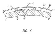
- FIG. 4is a cross section of an implanted patch.
- the patch 10includes a fixation section 12 , a rim 14 and a connection junction 16 .
- the rim 14defines a lumen 18 , which in one configuration extends completely around the rim. In other configurations, the rim lumen 18 may only extend partially around the rim, for example, between the connection junction 16 and the distal region 20 of the rim.
- connection junction 16is joined to the rim 14 at the proximal region 22 of the rim and includes a lumen 24 that communicates with the rim lumen 18 .
- the connection junction 16may be a separate part that is secured to the rim 14 using bonding, gluing or other chemical or mechanical means.
- the connection junction 16may be formed as an integral part of the rim 14 .
- the rim 14completely surrounds the fixation section 12 .
- the rim 14may only partially surround the fixation section 12 , for example by extending one-half or three-quarters of the way around the fixation section 12 .
- the fixation section 12is formed to have sufficient flexibility to allow for the section to assume a collapsed state upon the application of force.
- the fixation section 12may be made of a polyester polymer with an open weave mesh, such as a Dacron mesh.
- the fixation section 12may also be formed to exhibit elastic properties, for example, by the inclusion of an elastomeric material.
- the fixation section 12may be formed of polyester polymer woven together with an elastic metal to form a mesh. The elasticity of the fixation section allows the fixation section to resume its expanded state upon the removal of a collapsing force.
- the fixation sectionhas a large enough surface area to induce a sufficient degree of tissue over growth to provide stable, chronic fixation of the patch 10 to the myocardium.
- the thickness of the fixation section 12 and variations of its structuremay also be used to achieve desired fixation results. For example in the case of a mesh section, the weave structure may be made looser or tighter to achieve different results.
- the stability of the patch 10increases with increasing surface area of the fixation section 12 . Therefore, the surface area of the fixation section 12 may be varied in accordance with the size of the MI site and doctor preference.
- the patchmay have a bidirectional configuration ( FIG. 1 b ) or a unidirectional configuration ( FIG. 1 c ).
- the rim 14 and the fixation section 12are secured together such that the fixation section lies within the inner perimeter 15 of the rim.
- the patch 10may be implanted with either side of the fixation section 12 adjacent the epicardial surface of the heart.
- the rim 14may be described as having an epicardial side 17 and a pericardial-sac side 19 .
- the fixation section 12may be described as having an epicardial side 23 and a pericardial-sac side 25 .
- the fixation section 12is secured to epicardial side of the rim 14 .
- the patch 10is implanted so the epicardial sides 17 , 23 of the rim 14 and fixation section 12 are adjacent the epicardial surface of the heart.
- the fixation section 12may include a fluoroscopic marker, such as the letter S, on its epicardial side 23 . Under fluoroscopy, improper orientation of the patch 10 is detected if the letter S appears backwards.
- a layer of anti-fibrosis material 21such as silicone, may be applied to the pericardial-sac side 25 of the fixation section 25 to prevent fibrosis attachment between the pericardial sac and the patch 10 .
- Anti-fibrosis materialmay also be applied to other areas of the patch 10 , such as the pericardial-sac side 19 of the rim 14 .
- the rim 14 and fixation section 12are secured together using bonding, gluing, suturing or any other chemical or mechanical means.
- the rim 14may be configured as a coil, formed of a biocompatible metal having elastic properties, such as MP35N.
- a coiled rim 14may also be formed of Nitinol. In this configuration the inside of the coil defines the rim lumen 18 .
- the rim 14may be configured as a tube, formed of a biocompatible polymer, such as silicone, polyurethane or PEEK, ePTFE etc.
- the rimmay include both tube and coil aspects, such as alternating segments of tube and coil.
- the rim 14may also be molded onto the fixation section 12 .
- the rim 14like the fixation section 12 , is formed to have sufficient flexibility to allow the rim to assume a collapsed state upon the application of force.
- the rim 14is further formed to exhibit elastic properties that allow the rim to resume its expanded state upon the removal of a collapsing force.
- the rim 14Through its attachment to the fixation section 12 , the rim 14 —with its elastic property—functions to force the fixation section to return to its expanded state regardless of whether the fixation section itself is elastic.
- connection junction 16 of a patch 10engages the distal end 26 of an elongated body 28 and is held securely in place, as shown in FIG. 2 b .
- the elongated body 28is adapted to slide through an introducer and includes a lumen 30 for feeding a stylet into the connection junction 16 of the patch 10 .
- the elongated body 28includes a coil structure along its length and an insulating sheath made of biocompatible material such as silicone or polyurethane, similar to that included in cardiac leads. The coil allows for torque transmission between the proximal and distal ends of the body.
- connection between the elongated body 28 and the connection junction 16is provided by mechanical means such as a friction fit or a threaded junction.
- mechanical meanssuch as a friction fit or a threaded junction.
- the respective inner and outer diameters of the elongated body 28 and the connection junction 16are sized to fit tightly together.
- threaded junctionthe elongated body 28 and the connection junction 16 include mating screw threads.
- a stylet 32is inserted through the series of lumens 30 , 24 , 18 to the distal region 20 of the rim 14 .
- the styletforces the rim 14 to assume a collapsed state, which in turn forces the fixation section 12 to collapse.
- the collapsed patch 10is then implanted into the pericardium sac through an introducer using an implantation technique, such as a subxiphoid technique, which is described later below with reference to FIG. 3 . If the patch is too thick to be collapsed, it can be rolled up and pushed through the introducer.
- the rim 14is typically more rigid than the fixation section 12 and thus provides increased mechanical stability to the fixation section. Also, as described further below, during patch 10 implant the elasticity of the rim promotes full expansion of the fixation section 12 , which ensures sufficient coupling of the section to the heart surface.
- the stylet 32upon implantation of the patch 10 at the desired location on the epicardial surface, the stylet 32 is removed and the rim 14 and fixation section 12 assume their expanded states, as shown in FIG. 2 b .
- the location of the patch 10is manipulated using the elongated body 28 .
- the elongated body 28is disconnected from the rim 14 as shown in FIG. 2 d .
- the bodyIn the case of a friction fit between the elongated body 28 and the connection junction 18 , the body is disconnected by pulling on the elongated body.
- the body 28In the case of a threaded junction, the body 28 is disconnected by rotating the body until it disengages the threads of the connection junction 18 .
- the elongated body 28is then removed from the patient, leaving only the patch 10 , as shown in FIG. 2 e.
- one or more intercostal or subxyphoid incisions 40 for receiving various instrumentsare made in the mid-chest region 42 of a patient.
- FIG. 3illustrates one incision, it will be evident that two or more incisions may also be employed.
- the precise locations and sizes of the incisions and the instruments usedmay vary depending upon the patient's anatomy and the surgeon's preferences.
- Each incisionmay accommodate a trocar (not shown) for facilitating the insertion and manipulation of one of the instruments.
- a puncture needle(not shown) having a center lumen is inserted into the mid-chest region 42 via a subxiphoid or intercostal approach and introduced into the pericardial space 44 through a puncture 46 in the pericardial sac 48 .
- the needleis guided through the pericardial space using fluoroscopic or X-ray imaging and small amounts of contrast media. Alternatively, endoscopy or ultrasound can also be used for visualization during the implant procedure.
- a guidewireis inserted into the needle and advanced into the pericardial space.
- a dilator (not shown) and an introducer 50are then advanced over the guidewire and into the pericardial space 44 to expand the passageway through the puncture site 46 . Once inside the pericardial space 44 the dilator and guidewire may be removed.
- the patch 10is then positioned in the pericardial space 44 at a desired location through the introducer 50 using a stylet 32 as previously described with reference to FIGS. 2 a - 2 e .
- the desirable locationis over a MI site 52 , which may be determined prior to or during patch implant using well known techniques in the art, such as echo-graphic imaging.
- the pericardium 54pushes down on the rim 14 to promote good contact between the fixation section 12 and the epicardial surface 56 at the MI site and thereby provides acute fixation of the patch. Additional acute fixation of the patch 10 may be provided by applying adhesive between the patch and the epicardial surface 56 .
- the adhesivemay be a light-activated acrylic or cyanoacrylate adhesive such as those offered by Loctite Corporation, Rocky Hill, Conn.
- Loctite® acrylic adhesives and Loctite® FlashCureTM cyanoacrylate adhesivescan be cured upon exposure to UV light or Cyanoacrylate surgical adhesive such as Eastman 910, or Indermil® tissue Adhesive by syneture or the biocompatible glues like Coseal® and Tisseel® by Baxter, or Bioglue by CryoLife.
- Cyanoacrylate surgical adhesivesuch as Eastman 910, or Indermil® tissue Adhesive by syneture or the biocompatible glues like Coseal® and Tisseel® by Baxter, or Bioglue by CryoLife.
- UV adhesiveanother access to intrapericardial space may be needed for delivering the UV light to the adhesive.
- the adhesivemay be applied by injection through the lumen 30 ( FIG. 2 a ) of the elongated body 28 .
- the adhesiveseeps through the space between coils, thereby gluing the patch 10 to the epicardium.
- holesmay be provided in the rim to allow for the glue to pass through.
- the adhesivemay be delivered between the patch 10 and the epicardial surface through a separate delivery device inserted in the pericardial space or through a common delivery device including a first port for delivering the patch 10 and a second port for injecting the adhesive.
- an elongated bodyis not used. Instead, a stylet 30 is inserted through the connection junction 16 up to the distal end 20 of the patch 10 to collapse the rim 14 and fixation section 12 . The patch 10 and stylet 30 are then inserted into the introducer 50 and the stylet is used to push the patch 10 through the introducer into the pericardial space.
Landscapes
- Health & Medical Sciences (AREA)
- Cardiology (AREA)
- Oral & Maxillofacial Surgery (AREA)
- Transplantation (AREA)
- Engineering & Computer Science (AREA)
- Biomedical Technology (AREA)
- Heart & Thoracic Surgery (AREA)
- Vascular Medicine (AREA)
- Life Sciences & Earth Sciences (AREA)
- Animal Behavior & Ethology (AREA)
- General Health & Medical Sciences (AREA)
- Public Health (AREA)
- Veterinary Medicine (AREA)
- Prostheses (AREA)
Abstract
Description
Claims (19)
Priority Applications (1)
| Application Number | Priority Date | Filing Date | Title |
|---|---|---|---|
| US11/354,698US7922648B1 (en) | 2006-02-14 | 2006-02-14 | Myocardial infarction patch for minimally invasive implant |
Applications Claiming Priority (1)
| Application Number | Priority Date | Filing Date | Title |
|---|---|---|---|
| US11/354,698US7922648B1 (en) | 2006-02-14 | 2006-02-14 | Myocardial infarction patch for minimally invasive implant |
Publications (1)
| Publication Number | Publication Date |
|---|---|
| US7922648B1true US7922648B1 (en) | 2011-04-12 |
Family
ID=43837076
Family Applications (1)
| Application Number | Title | Priority Date | Filing Date |
|---|---|---|---|
| US11/354,698Expired - Fee RelatedUS7922648B1 (en) | 2006-02-14 | 2006-02-14 | Myocardial infarction patch for minimally invasive implant |
Country Status (1)
| Country | Link |
|---|---|
| US (1) | US7922648B1 (en) |
Cited By (2)
| Publication number | Priority date | Publication date | Assignee | Title |
|---|---|---|---|---|
| US20080319255A1 (en)* | 2007-06-21 | 2008-12-25 | Acorn Cardiovascular, Inc. | Pericardial space imaging for cardiac support device implantation |
| EP3476385A1 (en)* | 2017-10-27 | 2019-05-01 | AdjuCor GmbH | Collapsible myocardial patch |
Citations (19)
| Publication number | Priority date | Publication date | Assignee | Title |
|---|---|---|---|---|
| US4030509A (en)* | 1975-09-30 | 1977-06-21 | Mieczyslaw Mirowski | Implantable electrodes for accomplishing ventricular defibrillation and pacing and method of electrode implantation and utilization |
| US4827932A (en)* | 1987-02-27 | 1989-05-09 | Intermedics Inc. | Implantable defibrillation electrodes |
| US5042463A (en)* | 1990-05-23 | 1991-08-27 | Siemens-Pacesetter, Inc. | Patch electrode for heart defibrillator |
| US5122155A (en)* | 1990-10-11 | 1992-06-16 | Eberbach Mark A | Hernia repair apparatus and method of use |
| US5324328A (en)* | 1992-08-05 | 1994-06-28 | Siemens Pacesetter, Inc. | Conductor for a defibrillator patch lead |
| US5330524A (en)* | 1991-09-13 | 1994-07-19 | Ventritex, Inc. | Defibrillation electrode with mesh configuration |
| US5336254A (en)* | 1992-09-23 | 1994-08-09 | Medtronic, Inc. | Defibrillation lead employing electrodes fabricated from woven carbon fibers |
| US5366460A (en)* | 1990-10-11 | 1994-11-22 | Cook Incorporated | Apparatus and method for laparoscope hernia repair |
| US5391200A (en)* | 1992-09-30 | 1995-02-21 | Cardiac Pacemakers, Inc. | Defibrillation patch electrode having conductor-free resilient zone for minimally invasive deployment |
| US5702343A (en)* | 1996-10-02 | 1997-12-30 | Acorn Medical, Inc. | Cardiac reinforcement device |
| US20010018549A1 (en)* | 2000-01-21 | 2001-08-30 | Victor Scetbon | Percutaneous device and method for treating urinary stress incontinence in women using a sub-urethral tape |
| US6293906B1 (en)* | 2000-01-14 | 2001-09-25 | Acorn Cardiovascular, Inc. | Delivery of cardiac constraint jacket |
| US20020151868A1 (en) | 2001-03-02 | 2002-10-17 | Syde Taheri | Percutaneous epicardial injection |
| US6695769B2 (en) | 2001-09-25 | 2004-02-24 | The Foundry, Inc. | Passive ventricular support devices and methods of using them |
| WO2004019592A1 (en) | 2002-08-21 | 2004-03-04 | Matsushita Electric Industrial Co., Ltd. | Network terminal device, address management server, communication system, and network communication method using mac addresses to determine the ip target addresses |
| US20040208845A1 (en) | 2003-04-15 | 2004-10-21 | Michal Eugene T. | Methods and compositions to treat myocardial conditions |
| US20050187620A1 (en) | 2003-11-14 | 2005-08-25 | Suresh Pai | Systems for heart treatment |
| US7060023B2 (en)* | 2001-09-25 | 2006-06-13 | The Foundry Inc. | Pericardium reinforcing devices and methods of using them |
| US7270669B1 (en)* | 2002-03-14 | 2007-09-18 | Medtronic, Inc. | Epicardial lead placement for bi-ventricular pacing using thoracoscopic approach |
- 2006
- 2006-02-14USUS11/354,698patent/US7922648B1/ennot_activeExpired - Fee Related
Patent Citations (20)
| Publication number | Priority date | Publication date | Assignee | Title |
|---|---|---|---|---|
| US4030509A (en)* | 1975-09-30 | 1977-06-21 | Mieczyslaw Mirowski | Implantable electrodes for accomplishing ventricular defibrillation and pacing and method of electrode implantation and utilization |
| US4827932A (en)* | 1987-02-27 | 1989-05-09 | Intermedics Inc. | Implantable defibrillation electrodes |
| US5042463A (en)* | 1990-05-23 | 1991-08-27 | Siemens-Pacesetter, Inc. | Patch electrode for heart defibrillator |
| US5122155A (en)* | 1990-10-11 | 1992-06-16 | Eberbach Mark A | Hernia repair apparatus and method of use |
| US5366460A (en)* | 1990-10-11 | 1994-11-22 | Cook Incorporated | Apparatus and method for laparoscope hernia repair |
| US5330524A (en)* | 1991-09-13 | 1994-07-19 | Ventritex, Inc. | Defibrillation electrode with mesh configuration |
| US5324328A (en)* | 1992-08-05 | 1994-06-28 | Siemens Pacesetter, Inc. | Conductor for a defibrillator patch lead |
| US5336254A (en)* | 1992-09-23 | 1994-08-09 | Medtronic, Inc. | Defibrillation lead employing electrodes fabricated from woven carbon fibers |
| US5391200A (en)* | 1992-09-30 | 1995-02-21 | Cardiac Pacemakers, Inc. | Defibrillation patch electrode having conductor-free resilient zone for minimally invasive deployment |
| US5702343A (en)* | 1996-10-02 | 1997-12-30 | Acorn Medical, Inc. | Cardiac reinforcement device |
| US6293906B1 (en)* | 2000-01-14 | 2001-09-25 | Acorn Cardiovascular, Inc. | Delivery of cardiac constraint jacket |
| US20010018549A1 (en)* | 2000-01-21 | 2001-08-30 | Victor Scetbon | Percutaneous device and method for treating urinary stress incontinence in women using a sub-urethral tape |
| US20020151868A1 (en) | 2001-03-02 | 2002-10-17 | Syde Taheri | Percutaneous epicardial injection |
| US6659950B2 (en) | 2001-03-02 | 2003-12-09 | Syde Taheri | Percutaneous epicardial injection |
| US6695769B2 (en) | 2001-09-25 | 2004-02-24 | The Foundry, Inc. | Passive ventricular support devices and methods of using them |
| US7060023B2 (en)* | 2001-09-25 | 2006-06-13 | The Foundry Inc. | Pericardium reinforcing devices and methods of using them |
| US7270669B1 (en)* | 2002-03-14 | 2007-09-18 | Medtronic, Inc. | Epicardial lead placement for bi-ventricular pacing using thoracoscopic approach |
| WO2004019592A1 (en) | 2002-08-21 | 2004-03-04 | Matsushita Electric Industrial Co., Ltd. | Network terminal device, address management server, communication system, and network communication method using mac addresses to determine the ip target addresses |
| US20040208845A1 (en) | 2003-04-15 | 2004-10-21 | Michal Eugene T. | Methods and compositions to treat myocardial conditions |
| US20050187620A1 (en) | 2003-11-14 | 2005-08-25 | Suresh Pai | Systems for heart treatment |
Cited By (6)
| Publication number | Priority date | Publication date | Assignee | Title |
|---|---|---|---|---|
| US20080319255A1 (en)* | 2007-06-21 | 2008-12-25 | Acorn Cardiovascular, Inc. | Pericardial space imaging for cardiac support device implantation |
| US8718746B2 (en)* | 2007-06-21 | 2014-05-06 | Mardil, Inc. | Pericardial space imaging for cardiac support device implantation |
| US10159781B2 (en) | 2007-06-21 | 2018-12-25 | Mardil, Inc. | Pericardial space imaging for cardiac support device implantation |
| EP3476385A1 (en)* | 2017-10-27 | 2019-05-01 | AdjuCor GmbH | Collapsible myocardial patch |
| CN109718196A (en)* | 2017-10-27 | 2019-05-07 | 阿德尤科有限公司 | Folding cardiac muscle patch |
| CN109718196B (en)* | 2017-10-27 | 2024-02-13 | 阿德尤科有限公司 | Foldable cardiac muscle patch |
Similar Documents
| Publication | Publication Date | Title |
|---|---|---|
| US10639410B2 (en) | Devices, methods and systems for establishing supplemental blood flow in the circulatory system | |
| US11027103B2 (en) | Conduit device and system for implanting a conduit device in a tissue wall | |
| US10143823B2 (en) | Interventional medical systems and improved assemblies thereof and associated methods of use | |
| US20160051800A1 (en) | Vascular conduit device and system for implanting | |
| US20070055303A1 (en) | Endovascular splinting devices and methods | |
| US20250195211A1 (en) | Percutaneous tricuspid valve repair devices and methods | |
| US9717830B2 (en) | Inflow cannula and blood flow assist system | |
| US7922648B1 (en) | Myocardial infarction patch for minimally invasive implant | |
| JP2025510412A (en) | Clips for implantation in the heart and great vessels allowing their complete or partial removal, kits and methods for performing such removal - Patents.com | |
| HK1188577B (en) | Devices and systems for establishing supplemental blood flow in the circulatory system | |
| CN104582637A (en) | Devices, systems and methods for transcatheter treatment of valvular regurgitation | |
| HK1209616B (en) | Device, system, and method for transcatheter treatment of valve regurgitation | |
| HK1127474B (en) | Systems for establishing supplemental blood flow in the circulatory system |
Legal Events
| Date | Code | Title | Description |
|---|---|---|---|
| AS | Assignment | Owner name:PACESETTER, INC., CALIFORNIA Free format text:ASSIGNMENT OF ASSIGNORS INTEREST;ASSIGNORS:HOU, WENBO;WILLIAMS, SHELDON;REEL/FRAME:017580/0894 Effective date:20060213 | |
| STCF | Information on status: patent grant | Free format text:PATENTED CASE | |
| REMI | Maintenance fee reminder mailed | ||
| FPAY | Fee payment | Year of fee payment:4 | |
| SULP | Surcharge for late payment | ||
| MAFP | Maintenance fee payment | Free format text:PAYMENT OF MAINTENANCE FEE, 8TH YEAR, LARGE ENTITY (ORIGINAL EVENT CODE: M1552); ENTITY STATUS OF PATENT OWNER: LARGE ENTITY Year of fee payment:8 | |
| FEPP | Fee payment procedure | Free format text:MAINTENANCE FEE REMINDER MAILED (ORIGINAL EVENT CODE: REM.); ENTITY STATUS OF PATENT OWNER: LARGE ENTITY | |
| LAPS | Lapse for failure to pay maintenance fees | Free format text:PATENT EXPIRED FOR FAILURE TO PAY MAINTENANCE FEES (ORIGINAL EVENT CODE: EXP.); ENTITY STATUS OF PATENT OWNER: LARGE ENTITY | |
| STCH | Information on status: patent discontinuation | Free format text:PATENT EXPIRED DUE TO NONPAYMENT OF MAINTENANCE FEES UNDER 37 CFR 1.362 | |
| FP | Lapsed due to failure to pay maintenance fee | Effective date:20230412 |