US7922269B2 - Cabinet assembly including a scissors lift - Google Patents
Cabinet assembly including a scissors liftDownload PDFInfo
- Publication number
- US7922269B2 US7922269B2US11/975,363US97536307AUS7922269B2US 7922269 B2US7922269 B2US 7922269B2US 97536307 AUS97536307 AUS 97536307AUS 7922269 B2US7922269 B2US 7922269B2
- Authority
- US
- United States
- Prior art keywords
- cabinet
- scissors lift
- linkages
- scissors
- screw drive
- Prior art date
- Legal status (The legal status is an assumption and is not a legal conclusion. Google has not performed a legal analysis and makes no representation as to the accuracy of the status listed.)
- Expired - Fee Related, expires
Links
Images


Classifications
- H—ELECTRICITY
- H05—ELECTRIC TECHNIQUES NOT OTHERWISE PROVIDED FOR
- H05K—PRINTED CIRCUITS; CASINGS OR CONSTRUCTIONAL DETAILS OF ELECTRIC APPARATUS; MANUFACTURE OF ASSEMBLAGES OF ELECTRICAL COMPONENTS
- H05K7/00—Constructional details common to different types of electric apparatus
- H05K7/18—Construction of rack or frame
- H05K7/186—Construction of rack or frame for supporting telecommunication equipment
- H—ELECTRICITY
- H04—ELECTRIC COMMUNICATION TECHNIQUE
- H04Q—SELECTING
- H04Q1/00—Details of selecting apparatus or arrangements
- H04Q1/02—Constructional details
- H—ELECTRICITY
- H04—ELECTRIC COMMUNICATION TECHNIQUE
- H04Q—SELECTING
- H04Q1/00—Details of selecting apparatus or arrangements
- H04Q1/02—Constructional details
- H04Q1/021—Constructional details using pivoting mechanisms for accessing the interior of the apparatus
- H—ELECTRICITY
- H04—ELECTRIC COMMUNICATION TECHNIQUE
- H04Q—SELECTING
- H04Q1/00—Details of selecting apparatus or arrangements
- H04Q1/02—Constructional details
- H04Q1/023—Constructional details using sliding mechanisms for accessing the interior of the apparatus
- H—ELECTRICITY
- H04—ELECTRIC COMMUNICATION TECHNIQUE
- H04Q—SELECTING
- H04Q1/00—Details of selecting apparatus or arrangements
- H04Q1/02—Constructional details
- H04Q1/025—Cabinets
Definitions
- the present inventionrelates to a scissors lift. More specifically, the present invention relates to a cabinet assembly including a scissors lift.
- Fiber distribution hubsprovide an enclosure for fiber optic routing equipment, such as splices and other equipment.
- the cabinetsare generally mounted to utility poles at an elevated location out of reach or view from a human. Installation of cabinets at such heights avoids clearance, vandalism, or right of way issues which may otherwise occur.
- a scissors liftfor a cabinet assembly.
- a scissors liftis disclosed.
- the scissors liftis mountable to a utility pole and includes a plurality of linkages.
- the scissors liftis moveable between extended and retracted positions.
- the scissors liftalso includes a drive mechanism for moving the linkages at the desired time to raise and lower equipment mounted to the linkages by moving the scissors lift between the extended and retracted positions.
- the cabinet assemblyfurther includes a cabinet mounted to the scissors lift and moveable between raised and lowered positions.
- a telecommunications cabinet assemblyincludes a scissors lift fastened to a utility pole at a raised position.
- the scissors liftincludes a plurality of linkages and a drive mechanism, and is oriented downwardly and moveable between extended and retracted positions.
- the telecommunications cabinet assemblyalso includes a telecommunications cabinet mounted to the scissors lift and moveable between the raised position and a lowered position by extending the scissors lift from the retracted position to the extended position.
- a method of accessing a telecommunications cabinetincludes extending a scissors lift to move a telecommunications cabinet from a raised position to a lowered position.
- the methodalso includes accessing the interior of the telecommunications cabinet.
- the methodfurther includes retracting the scissors lift to move the telecommunications cabinet from the lowered position to the raised position.
- a scissors lift for a telecommunications cabinetincludes a mount mountable to a utility pole and a plurality of scissors linkages.
- the scissors liftfurther includes a drive mechanism interfaced with the plurality of scissors linkages and configured to move the linkages between extended and retracted positions, wherein the drive mechanism includes a screw drive and a plurality of support bands affixed to the plurality of scissors linkages.
- the drive mechanismincludes a screw drive and a plurality of support bands affixed to the plurality of scissors linkages.
- one of the support bandsincludes a threaded interior configured to interlock with the screw drive.
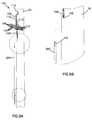
- FIG. 1is a schematic perspective rear view of a cabinet assembly in a raised position mounted to a utility pole;
- FIG. 2Ais a schematic perspective rear view of the cabinet assembly of FIG. 1 in a lowered position and mounted to a utility pole;
- FIG. 2Bis a schematic perspective front view of the cabinet assembly of FIG. 1 in a lowered position and mounted to a utility pole;
- FIG. 3is a schematic perspective front view of the cabinet assembly of FIG. 1 in a lowered position and mounted to a utility pole;
- FIG. 4Ais an exploded view of the cabinet assembly of FIG. 1 mounted to a utility pole;
- FIG. 4Bis a perspective view of the cabinet assembly of FIG. 1 mounted to a utility pole;
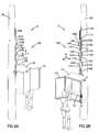
- FIG. 5Ais a perspective view of a portion of a utility pole having a scissors lift mounted thereon;
- FIG. 5Bis a perspective view of the interface between an extension drive rod and screw drive of FIG. 5A ;
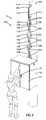
- FIG. 6Ais a perspective view of a portion of a utility pole having a scissors lift mounted thereon;
- FIG. 6Bis a side view of the utility pole and scissors lift of FIG. 6A .
- the present disclosurerelates to a cabinet assembly mountable to a utility pole.
- the cabinet assemblyincludes a cabinet and a scissors lift.
- the scissors liftis driven by a drive mechanism between a retracted position and an extended position so as to move the cabinet between raised and lowered positions, respectively.
- the cabinet assembly 2is shown mounted to a utility pole 20 .
- the cabinet assembly 2includes a cabinet 10 and a scissors lift 100 .
- the cabinet 10is configured to include telecommunications equipment.
- the cabinet 10is a fiber distribution hub in which a fiber optic distribution cable is separated by splices into a number of fiber ribbons which in turn are routed out of the fiber distribution hub.
- An example of such a cabinetis shown and described in U.S. Pat. No. 6,983,095, entitled “Systems and Methods for Managing Optical Fibers and Components Within an Enclosure in an Optical Network” and assigned to Fiber Optic Network Solutions Corp., the disclosure of which is hereby incorporated by reference in its entirety.
- a variety of other types of telecommunications equipmentmay be stored in the cabinet.
- the cabinet 10 as shownis generally rectangular, having front and rear faces and side panels.
- the cabinethas doors 12 configured to swing open and closed from hinges located along front vertical edges. In the embodiment shown in FIG. 1 , the doors 12 are in an open position. Other sizes and configurations of the cabinet are possible as well.
- the cabinet 10is mounted to the utility pole 20 such that the cabinet 10 generally resides at a raised position when the scissors lift 100 is retracted, preferably at a height not easily reachable by a human. In a possible embodiment, the cabinet resides at a raised position eight or more feet off the ground.
- the scissors lift 100is oriented and extendable downwardly, and provides an adjustable mount by which the cabinet 10 mounts to a utility pole 20 .
- the scissors lift 100includes a mounting arrangement 102 , a plurality of linkages 104 , and a drive mechanism 107 (shown most clearly in FIGS. 6A-6B , below) configured to raise and lower the cabinet along the utility pole 20 , as described below.
- the scissors lift 100when the cabinet 10 is in a raised position shown in FIG. 1 , the scissors lift 100 is in a retracted position. Conversely, when the cabinet 10 is in a lowered position as shown below in FIGS. 2A-2B and FIG. 3 , the scissors lift 100 is in an extended position.
- Other embodimentsare possible as well, such as an embodiment in which the scissors lift 100 is in an extended position when the cabinet 10 is in a raised position and the scissors lift is moved to a retracted position when the cabinet is in a lowered position.
- the mounting arrangement 102affixes the scissors lift 100 to a vertical surface, such as the utility pole 20 . Additionally, the mounting arrangement 102 allows mounting of the cabinet assembly 2 to surfaces other than the utility pole 20 . For example, the cabinet assembly 2 can be mounted to a wall or other vertical surface.
- the linkages 104each include a pair of bars 103 pivotally connected at a central point.
- the linkages 104are also pivotally interconnected at hinge points 105 located at each end of the bars 103 .
- the scissors lift 100extends downwardly from a retracted position to an extended position.
- FIGS. 2A-2Bshow front and rear views, respectively, of the cabinet 10 of FIG. 1 with the scissors lift 100 in an extended position so as to move the cabinet to a lowered position on the utility pole 20 .
- a repairpersoncan open the doors 12 to access an interior 14 of the cabinet 10 while standing on the ground near the utility pole 20 .
- the drive mechanism 107connects to the mounting arrangement 102 and the linkages 104 , as shown below in FIGS. 6A-6B , to drive the scissors lift 100 between extended and retracted positions. Movement of the scissors lift 100 between extended and retracted positions causes movement of the cabinet 10 between lowered and raised positions, respectively.
- the drive mechanism 107includes a screw drive 106 rotatably mounted in a downward orientation from a support bar 113 , and drives vertical movement of the cabinet by causing the linkages 104 to pivot.
- FIG. 3shows the cabinet 10 of FIG. 1 in a closed position and with the scissors lift 100 extended to move the cabinet to a lowered position on the utility pole 20 .
- a user of the cabinet assembly 2can lower the cabinet 10 prior to opening the doors 12 , allowing for ease of opening.
- the lowered cabineteliminates a disadvantage of a stationary elevated cabinet, in that a repairperson or other user encountering a stationary elevated cabinet must use a ladder to reach the cabinet; however, the ladder must be leaned on the pole. Opening the cabinet doors 12 can therefore be awkward because the underside of the cabinet 10 forms an overhang above the ladder.
- FIGS. 4A-4Billustrate the construction of the cabinet assembly 2 .
- the cabinet assembly 2includes the cabinet and the scissors lift 100 .
- the scissors lift 100is configured to affix the cabinet 10 to the utility pole 20 .
- the scissors lift 100includes the mounting arrangement 102 , as well as linkages 104 , a drive mechanism 107 , a sleeve 108 , and guide blocks 110 .
- the mounting arrangement 102affixes the scissors lift 100 to the pole 20 , and includes fasteners 114 and support bars 112 , 113 .
- the fasteners 114can be nails, bolts, screws, clamps, or other fastening equipment. In the embodiment shown, two fasteners are used. One fastener is a screw inserted into the utility pole 20 , and a second fastener is a bolt passed through a hole drilled through the utility pole 20 .
- Two linkages 104pivotally mount to the support bar 112 . Subsequent linkages of the plurality of linkages 104 in turn connect to those linkages to form a lattice arrangement with pivotal interconnections at the ends and midpoints of each linkage, as previously described.
- the sleeve 108is vertically affixed to the cabinet 10 and slides along guide blocks 110 located at midpoints along each linkage 104 .
- the sleeve 108defines a slot 109 and an interior volume 111 .
- the sleeve 108is fixedly attached to a lowermost guide block 110 and allows the other guide blocks 110 and the support bar 112 to reside within the interior volume 111 by sliding along the slot 109 .
- the sleeve 108is longer than the distance between adjacent guide blocks 110 when the scissors lift 100 is in an extended position.
- the guide blocks 110are held within the sleeve 108 at any time, including the lowest guide block 110 which is affixed to the cabinet 10 , preferably within the sleeve.
- the guide blocks 110thereby coordinate with the sleeve 108 to maintain the vertical orientation of the cabinet 10 in both the raised and lowered positions.
- FIGS. 5A-5Bshow a possible mechanism for controlling the scissors lift 100 to control the height of the cabinet 10 .
- a drive bar 200includes a non-rotatable connection to the screw drive 106 .
- the drive bar 200optionally has matching threading to the screw drive 106 , and includes a complementary hexagonal configuration arranged to non-rotatably accept insertion of an end portion of the screw drive 106 .
- the screw drive 106is inserted into the drive bar 200 , the bar can be rotated by a repairperson or machine without requiring that the person or machine be located at an elevated height to reach the screw drive 106 .
- Rotation of the drive bar 200causes the screw drive 106 to turn, thereby driving the scissors lift 100 between retracted and extended positions based on the selected direction of rotation.
- FIGS. 6A-6Bshow perspective and side views of the scissors lift 100 .
- a plurality of support bands 116are located at the midpoints of the linkages 104 on the opposite side from the guide blocks 110 .
- the support bands 116connect the linkages 104 to the screw drive 106 .
- One of the support bands 116has a threaded internal surface (not shown) complementary to the threaded screw drive 106 , while the other support bands 116 slide along the screw drive 106 .
- the threaded support band 116is configured to interlock with the screw drive, and is vertically moveable by rotation of the screw drive 106 .
- the remaining support bands 116remain unthreaded, and have an internal circumference sufficient to slide along the screw drive 106 as the threaded band is raised or lowered by rotation of the screw drive.
- Rotation of the screw drive 106 in a first directioncauses downward movement of the support bands 116 , thereby extending the linkages 104 and lowering the cabinet 10 .
- Rotation of the screw drive 106 in a second directioncauses upward movement of the support bands 116 , thereby contracting the linkages 104 and raising the cabinet 10 .
- the drive mechanism 107includes a screw drive 106 and the support bands 116 .
- the screw drive 106is rotatably mounted to the support bar 113 .
- a userrotates the screw drive 106 , which in turn raises or lowers (depending on the rotational direction of the screw drive) the support bands 116 and causes the linkages 104 to pivot, thereby extending the scissors lift 100 downwardly.
- the length and number of linkages 104are such that one or more of the support bands 116 can be lowered off of the screw drive 106 when the scissors lift 100 is in an extended position.
- the threaded support band 116screws onto the drive bar 200 , shown in FIGS. 5A-5B .
- the threaded support bandremains on the screw drive 106 .
- the support bands 116 that extend onto the drive bar 200are drawn back onto the screw drive 106 as the threaded support band 116 is raised to the retracted position by the screw drive 106 and optionally by the drive bar 200 .
- the scissors lift 100allows a repairperson or other individual requiring access to the cabinet 10 to extend the scissors lift 100 to lower the cabinet to a lowered position, open the cabinet, and perform any maintenance or repair operations required.
- the repairpersonWhen the repairperson has completed the maintenance or repair, they can retract the scissors lift 100 to raise the cabinet 10 to its raised position.
- a cradle or holdercan be added to support the cabinet 10 in the raised position.
- the cradle or other holderholds the cabinet 10 to the utility pole 20 so that the full weight of the cabinet 10 need not be continuously supported by the scissors lift 100 .
Landscapes
- Engineering & Computer Science (AREA)
- Computer Networks & Wireless Communication (AREA)
- Microelectronics & Electronic Packaging (AREA)
- Casings For Electric Apparatus (AREA)
Abstract
Description
Claims (18)
Priority Applications (1)
| Application Number | Priority Date | Filing Date | Title |
|---|---|---|---|
| US11/975,363US7922269B2 (en) | 2006-10-17 | 2007-10-17 | Cabinet assembly including a scissors lift |
Applications Claiming Priority (2)
| Application Number | Priority Date | Filing Date | Title |
|---|---|---|---|
| US85245006P | 2006-10-17 | 2006-10-17 | |
| US11/975,363US7922269B2 (en) | 2006-10-17 | 2007-10-17 | Cabinet assembly including a scissors lift |
Publications (2)
| Publication Number | Publication Date |
|---|---|
| US20080211364A1 US20080211364A1 (en) | 2008-09-04 |
| US7922269B2true US7922269B2 (en) | 2011-04-12 |
Family
ID=39732598
Family Applications (1)
| Application Number | Title | Priority Date | Filing Date |
|---|---|---|---|
| US11/975,363Expired - Fee RelatedUS7922269B2 (en) | 2006-10-17 | 2007-10-17 | Cabinet assembly including a scissors lift |
Country Status (1)
| Country | Link |
|---|---|
| US (1) | US7922269B2 (en) |
Cited By (2)
| Publication number | Priority date | Publication date | Assignee | Title |
|---|---|---|---|---|
| US20090072685A1 (en)* | 2007-09-19 | 2009-03-19 | Alcatel Lucent. | Flush to grade underground cabinet |
| CN108378582A (en)* | 2018-03-19 | 2018-08-10 | 合肥泓泉档案信息科技有限公司 | A kind of archiving flat-top cabinet |
Families Citing this family (4)
| Publication number | Priority date | Publication date | Assignee | Title |
|---|---|---|---|---|
| US20080231151A1 (en)* | 2007-03-22 | 2008-09-25 | International Business Machines Corporation | Assembly and method for ruggedizing computer racks |
| US7823694B2 (en)* | 2007-05-03 | 2010-11-02 | Motes Outdoor Equipment, Llc | Motorized climbing hunting stand |
| US10362710B2 (en) | 2014-10-01 | 2019-07-23 | American Products, L.L.C. | Below grade enclosure |
| CN116634299B (en)* | 2023-07-19 | 2023-09-26 | 深圳市迈拓诚悦科技有限公司 | Network communication equipment with stable operation |
Citations (40)
| Publication number | Priority date | Publication date | Assignee | Title |
|---|---|---|---|---|
| US39857A (en)* | 1863-09-08 | Improvement in elevating or scaling ladders | ||
| US495546A (en)* | 1893-04-18 | Alexander | ||
| US1215261A (en)* | 1916-04-14 | 1917-02-06 | Seng Co | Kitchen-cabinet. |
| US2462626A (en)* | 1947-01-27 | 1949-02-22 | Joseph E Forster | Portable fire escape |
| US2968520A (en)* | 1958-03-25 | 1961-01-17 | Loomis H Abrens | Garment cabinet |
| US3278247A (en)* | 1965-01-18 | 1966-10-11 | James R Tisdell | Cabinet |
| US4371222A (en)* | 1980-09-08 | 1983-02-01 | Gorkiewicz Mitchell F | Retractable scissors tong mechanism |
| US4541209A (en) | 1983-08-15 | 1985-09-17 | Jack E. Hoag | Vault mount for electrical apparatus |
| US4546852A (en)* | 1984-02-07 | 1985-10-15 | Fruehauf Corporation | Adjustable service platform apparatus for a gantry crane |
| US4749169A (en)* | 1983-11-04 | 1988-06-07 | Casco Products Corporation | Portable powered screw jack actuator unit |
| US4752110A (en) | 1985-11-18 | 1988-06-21 | Alcatel | Cabinet for an optical cable head |
| US4812004A (en) | 1986-11-29 | 1989-03-14 | Krone Ag | Splice cassette housing |
| US4827646A (en)* | 1987-06-05 | 1989-05-09 | Bradley Jay Miller | Vehicle sign display device |
| US4884863A (en) | 1989-03-06 | 1989-12-05 | Siecor Corporation | Optical fiber splicing enclosure for installation in pedestals |
| US5024498A (en) | 1988-11-12 | 1991-06-18 | U.S. Philips Corp. | Switch box for producing freely selectable optical plug connections |
| US5069516A (en) | 1989-11-21 | 1991-12-03 | Raynet Corporation | Telecommunications closures |
| US5109467A (en) | 1991-02-27 | 1992-04-28 | Keptel, Inc. | Interconnect cabinet for optical fibers |
| US5133038A (en) | 1980-04-17 | 1992-07-21 | Reliance Comm/Tec. Corporation | Fiber optic splice case |
| DE4140701C1 (en) | 1991-12-10 | 1992-12-10 | Siemens Ag, 8000 Muenchen, De | Buried container e.g. for fibre=optic cable junction - is partially held in shaft and has removable lid and lifting arrangement to allow easy working access e.g. for further splicing |
| US5189723A (en) | 1992-01-06 | 1993-02-23 | Adc Telecommunications, Inc. | Below ground cross-connect/splice sytem (BGX) |
| US5426577A (en)* | 1993-02-23 | 1995-06-20 | Musco Corporation | Pole-mounted lighting system |
| US5548678A (en) | 1993-09-10 | 1996-08-20 | British Telecommunications Public Limited Company | Optical fibre management system |
| US5588076A (en) | 1993-09-10 | 1996-12-24 | British Telecommunications Public Limited Company | Optical fibre management system |
| EP0840420A1 (en) | 1996-11-01 | 1998-05-06 | N.V. Raychem S.A. | Extension part for mounting bracket of cable closure |
| US5939669A (en) | 1996-11-15 | 1999-08-17 | Siemens Aktiengesellschaft | Underground container |
| US6028769A (en) | 1996-05-20 | 2000-02-22 | Adc Telecommunication, Inc. | Multiple integrated service unit for communication system |
| US6031180A (en) | 1997-07-18 | 2000-02-29 | Arco Communications, Inc. | Below ground pressurizable cable interconnect enclosure |
| US6181861B1 (en) | 1997-02-14 | 2001-01-30 | Alcatel | Arrangement for branching a telecommunications cable containing several stranded elements with optical fibers |
| US6185303B1 (en)* | 1997-12-23 | 2001-02-06 | Francis R. Losey | Enclosure mounting bracket |
| US6312067B1 (en)* | 1999-05-28 | 2001-11-06 | Douglas Blanchard | Organizing system for hunting safety |
| US6316728B1 (en) | 2000-01-06 | 2001-11-13 | Tyco Electronics Logistics Ag | Cross-connect cabinet |
| US20040063076A1 (en) | 2001-02-27 | 2004-04-01 | Wilhelmus Van Leest | Cable connection apparatus |
| US20050247136A1 (en) | 2004-05-07 | 2005-11-10 | Cross Joseph A | Wireline extensometer |
| US6983095B2 (en) | 2003-11-17 | 2006-01-03 | Fiber Optic Network Solutions Corporation | Systems and methods for managing optical fibers and components within an enclosure in an optical communications network |
| US7038127B2 (en) | 2004-02-27 | 2006-05-02 | Charles Industries, Ltd. | Universal mounting arrangement for components of an electronic enclosure |
| US20060269204A1 (en) | 2005-05-25 | 2006-11-30 | Michael Barth | Outside plant fiber distribution enclosure with radial arrangement |
| US20060278426A1 (en) | 2005-05-25 | 2006-12-14 | Michael Barth | Underground enclosure mounting system |
| US7190874B1 (en) | 2005-10-03 | 2007-03-13 | Adc Telecommunications, Inc. | Fiber demarcation box with cable management |
| US20070284980A1 (en)* | 2006-06-12 | 2007-12-13 | Peters Robert J | Outdoor desk and document storage cabinet |
| US7333320B2 (en) | 2005-05-25 | 2008-02-19 | Adc Telecommunications, Inc. | Systems and methods for lifting a terminal enclosure in below ground applications |
Family Cites Families (3)
| Publication number | Priority date | Publication date | Assignee | Title |
|---|---|---|---|---|
| US2634186A (en)* | 1950-04-17 | 1953-04-07 | Zuss Sidney | Display cabinet for stores and the like |
| US5285992A (en)* | 1992-07-14 | 1994-02-15 | Brown Ronald G | Adjustable step stool |
| IT247843Y1 (en)* | 1999-04-16 | 2002-09-10 | Firenze Ind Fototecnica | A LOAD SUSPENSION DEVICE, ESPECIALLY FOR LUMINAIRES FOR PHOTOGRAPHIC OR TELEVISION STUDIES. |
- 2007
- 2007-10-17USUS11/975,363patent/US7922269B2/ennot_activeExpired - Fee Related
Patent Citations (45)
| Publication number | Priority date | Publication date | Assignee | Title |
|---|---|---|---|---|
| US495546A (en)* | 1893-04-18 | Alexander | ||
| US39857A (en)* | 1863-09-08 | Improvement in elevating or scaling ladders | ||
| US1215261A (en)* | 1916-04-14 | 1917-02-06 | Seng Co | Kitchen-cabinet. |
| US2462626A (en)* | 1947-01-27 | 1949-02-22 | Joseph E Forster | Portable fire escape |
| US2968520A (en)* | 1958-03-25 | 1961-01-17 | Loomis H Abrens | Garment cabinet |
| US3278247A (en)* | 1965-01-18 | 1966-10-11 | James R Tisdell | Cabinet |
| US5133038A (en) | 1980-04-17 | 1992-07-21 | Reliance Comm/Tec. Corporation | Fiber optic splice case |
| US4371222A (en)* | 1980-09-08 | 1983-02-01 | Gorkiewicz Mitchell F | Retractable scissors tong mechanism |
| US4541209A (en) | 1983-08-15 | 1985-09-17 | Jack E. Hoag | Vault mount for electrical apparatus |
| US4749169A (en)* | 1983-11-04 | 1988-06-07 | Casco Products Corporation | Portable powered screw jack actuator unit |
| US4546852A (en)* | 1984-02-07 | 1985-10-15 | Fruehauf Corporation | Adjustable service platform apparatus for a gantry crane |
| US4752110A (en) | 1985-11-18 | 1988-06-21 | Alcatel | Cabinet for an optical cable head |
| US4812004A (en) | 1986-11-29 | 1989-03-14 | Krone Ag | Splice cassette housing |
| US4827646A (en)* | 1987-06-05 | 1989-05-09 | Bradley Jay Miller | Vehicle sign display device |
| US5024498A (en) | 1988-11-12 | 1991-06-18 | U.S. Philips Corp. | Switch box for producing freely selectable optical plug connections |
| US4884863A (en) | 1989-03-06 | 1989-12-05 | Siecor Corporation | Optical fiber splicing enclosure for installation in pedestals |
| US5069516A (en) | 1989-11-21 | 1991-12-03 | Raynet Corporation | Telecommunications closures |
| US5109467A (en) | 1991-02-27 | 1992-04-28 | Keptel, Inc. | Interconnect cabinet for optical fibers |
| DE4140701C1 (en) | 1991-12-10 | 1992-12-10 | Siemens Ag, 8000 Muenchen, De | Buried container e.g. for fibre=optic cable junction - is partially held in shaft and has removable lid and lifting arrangement to allow easy working access e.g. for further splicing |
| US5189723A (en) | 1992-01-06 | 1993-02-23 | Adc Telecommunications, Inc. | Below ground cross-connect/splice sytem (BGX) |
| US5426577A (en)* | 1993-02-23 | 1995-06-20 | Musco Corporation | Pole-mounted lighting system |
| US5588076A (en) | 1993-09-10 | 1996-12-24 | British Telecommunications Public Limited Company | Optical fibre management system |
| US5548678A (en) | 1993-09-10 | 1996-08-20 | British Telecommunications Public Limited Company | Optical fibre management system |
| US5706384A (en) | 1993-09-10 | 1998-01-06 | British Telecommunications Public Limited Company | Optical fibre management system |
| US6028769A (en) | 1996-05-20 | 2000-02-22 | Adc Telecommunication, Inc. | Multiple integrated service unit for communication system |
| EP0840420A1 (en) | 1996-11-01 | 1998-05-06 | N.V. Raychem S.A. | Extension part for mounting bracket of cable closure |
| US5939669A (en) | 1996-11-15 | 1999-08-17 | Siemens Aktiengesellschaft | Underground container |
| US6181861B1 (en) | 1997-02-14 | 2001-01-30 | Alcatel | Arrangement for branching a telecommunications cable containing several stranded elements with optical fibers |
| US6031180A (en) | 1997-07-18 | 2000-02-29 | Arco Communications, Inc. | Below ground pressurizable cable interconnect enclosure |
| US6185303B1 (en)* | 1997-12-23 | 2001-02-06 | Francis R. Losey | Enclosure mounting bracket |
| US6312067B1 (en)* | 1999-05-28 | 2001-11-06 | Douglas Blanchard | Organizing system for hunting safety |
| US6316728B1 (en) | 2000-01-06 | 2001-11-13 | Tyco Electronics Logistics Ag | Cross-connect cabinet |
| US20040063076A1 (en) | 2001-02-27 | 2004-04-01 | Wilhelmus Van Leest | Cable connection apparatus |
| US6983095B2 (en) | 2003-11-17 | 2006-01-03 | Fiber Optic Network Solutions Corporation | Systems and methods for managing optical fibers and components within an enclosure in an optical communications network |
| US7038127B2 (en) | 2004-02-27 | 2006-05-02 | Charles Industries, Ltd. | Universal mounting arrangement for components of an electronic enclosure |
| US20050247136A1 (en) | 2004-05-07 | 2005-11-10 | Cross Joseph A | Wireline extensometer |
| US20060269204A1 (en) | 2005-05-25 | 2006-11-30 | Michael Barth | Outside plant fiber distribution enclosure with radial arrangement |
| US20060278426A1 (en) | 2005-05-25 | 2006-12-14 | Michael Barth | Underground enclosure mounting system |
| US7260301B2 (en) | 2005-05-25 | 2007-08-21 | Adc Telecommunications, Inc. | Outside plant fiber distribution enclosure with radial arrangement |
| US7330625B2 (en) | 2005-05-25 | 2008-02-12 | Adc Telecommunications, Inc. | Underground enclosure mounting system |
| US7333320B2 (en) | 2005-05-25 | 2008-02-19 | Adc Telecommunications, Inc. | Systems and methods for lifting a terminal enclosure in below ground applications |
| US7633742B2 (en) | 2005-05-25 | 2009-12-15 | Adc Telecommunications, Inc. | Systems and methods for lifting a terminal enclosure in below ground applications |
| US7190874B1 (en) | 2005-10-03 | 2007-03-13 | Adc Telecommunications, Inc. | Fiber demarcation box with cable management |
| US7327926B2 (en) | 2005-10-03 | 2008-02-05 | Adc Telecommunications, Inc. | Fiber demarcation box with cable management |
| US20070284980A1 (en)* | 2006-06-12 | 2007-12-13 | Peters Robert J | Outdoor desk and document storage cabinet |
Non-Patent Citations (3)
| Title |
|---|
| ADC Telecommunications, Inc., "Fiber Outside Plant Systems," 1040 Aug. 1998 Revision © 1997, 1998, 12 Pages. |
| ADC Telecommunications, Inc., "FiberSeal® Outside Plant System," 1031, Jun. 1998 Revision © 1995, 1997, 1998, 12 Pages. |
| ADC Telecommunications, Inc., "Outside Plant FiberSeal® Terminal Enclosure Below Ground Application Installation Guide," ADCP-93-019, 1st Edition, Issue 4, pp. i-iv, 1-20 (Oct. 1997). |
Cited By (3)
| Publication number | Priority date | Publication date | Assignee | Title |
|---|---|---|---|---|
| US20090072685A1 (en)* | 2007-09-19 | 2009-03-19 | Alcatel Lucent. | Flush to grade underground cabinet |
| CN108378582A (en)* | 2018-03-19 | 2018-08-10 | 合肥泓泉档案信息科技有限公司 | A kind of archiving flat-top cabinet |
| CN108378582B (en)* | 2018-03-19 | 2020-07-10 | 合肥泓泉档案信息科技有限公司 | Flat-top cabinet for storing files |
Also Published As
| Publication number | Publication date |
|---|---|
| US20080211364A1 (en) | 2008-09-04 |
Similar Documents
| Publication | Publication Date | Title |
|---|---|---|
| US7922269B2 (en) | Cabinet assembly including a scissors lift | |
| US9723919B1 (en) | Combination foldable and adjustable workstation | |
| AU2015360366A1 (en) | Height adjustable monitor and keyboard support | |
| US8382052B1 (en) | Flat-screen television mounting methods and apparatus | |
| CN1417443A (en) | Door hinge with covered structure used between door and door frame | |
| EP1045099A2 (en) | Storage cabinet with handle operated door | |
| US8091969B2 (en) | Wall mount cabinet system | |
| US6752475B2 (en) | Storage apparatus | |
| CN111188527A (en) | Fixing device is used in installation of street lamp pole setting | |
| CN2548990Y (en) | Electric elevating rack | |
| US6668899B1 (en) | Laterally moving supports for horizontal blinds | |
| CN221343460U (en) | Grocery elevator control cabinet | |
| CN213403904U (en) | Three-in-one cabinet convenient for wiring of cabinet | |
| CN209488499U (en) | A kind of terrace-type solar energy frame | |
| CN222870053U (en) | Intelligent lifting operation platform | |
| CN112303444A (en) | Fully-hinged telescopic wall hanging frame and transportation method thereof | |
| CN214921608U (en) | Rotating platform convenient to operate and capable of reducing space | |
| CN216676780U (en) | Fire-fighting tool storage rack | |
| CN220699593U (en) | Lighting street lamp installation shop helps device | |
| CN214067468U (en) | Multifunctional communication optical cable distributing box | |
| CN219813733U (en) | Mirror mounting assembly and mirror | |
| CN118000006B (en) | Tree transplanting and planting protection device and application method thereof | |
| CN213299300U (en) | Double-locking anti-falling outdoor LED display screen | |
| CN221177859U (en) | Distribution frame for building intelligent engineering | |
| CN220325199U (en) | Cable rack for electronic communication engineering |
Legal Events
| Date | Code | Title | Description |
|---|---|---|---|
| AS | Assignment | Owner name:ADC TELECOMMUNICATIONS, INC., MINNESOTA Free format text:ASSIGNMENT OF ASSIGNORS INTEREST;ASSIGNORS:SOLHEID, JAMES J.;HOLMBERG, MATTHEW;SMITH, TREVOR D.;REEL/FRAME:021036/0194 Effective date:20080109 | |
| STCF | Information on status: patent grant | Free format text:PATENTED CASE | |
| FPAY | Fee payment | Year of fee payment:4 | |
| AS | Assignment | Owner name:TYCO ELECTRONICS SERVICES GMBH, SWITZERLAND Free format text:ASSIGNMENT OF ASSIGNORS INTEREST;ASSIGNOR:ADC TELECOMMUNICATIONS, INC.;REEL/FRAME:036060/0174 Effective date:20110930 | |
| AS | Assignment | Owner name:COMMSCOPE EMEA LIMITED, IRELAND Free format text:ASSIGNMENT OF ASSIGNORS INTEREST;ASSIGNOR:TYCO ELECTRONICS SERVICES GMBH;REEL/FRAME:036956/0001 Effective date:20150828 | |
| AS | Assignment | Owner name:COMMSCOPE TECHNOLOGIES LLC, NORTH CAROLINA Free format text:ASSIGNMENT OF ASSIGNORS INTEREST;ASSIGNOR:COMMSCOPE EMEA LIMITED;REEL/FRAME:037012/0001 Effective date:20150828 | |
| AS | Assignment | Owner name:JPMORGAN CHASE BANK, N.A., AS COLLATERAL AGENT, ILLINOIS Free format text:PATENT SECURITY AGREEMENT (TERM);ASSIGNOR:COMMSCOPE TECHNOLOGIES LLC;REEL/FRAME:037513/0709 Effective date:20151220 Owner name:JPMORGAN CHASE BANK, N.A., AS COLLATERAL AGENT, ILLINOIS Free format text:PATENT SECURITY AGREEMENT (ABL);ASSIGNOR:COMMSCOPE TECHNOLOGIES LLC;REEL/FRAME:037514/0196 Effective date:20151220 Owner name:JPMORGAN CHASE BANK, N.A., AS COLLATERAL AGENT, IL Free format text:PATENT SECURITY AGREEMENT (ABL);ASSIGNOR:COMMSCOPE TECHNOLOGIES LLC;REEL/FRAME:037514/0196 Effective date:20151220 Owner name:JPMORGAN CHASE BANK, N.A., AS COLLATERAL AGENT, IL Free format text:PATENT SECURITY AGREEMENT (TERM);ASSIGNOR:COMMSCOPE TECHNOLOGIES LLC;REEL/FRAME:037513/0709 Effective date:20151220 | |
| FEPP | Fee payment procedure | Free format text:MAINTENANCE FEE REMINDER MAILED (ORIGINAL EVENT CODE: REM.); ENTITY STATUS OF PATENT OWNER: LARGE ENTITY | |
| AS | Assignment | Owner name:ALLEN TELECOM LLC, ILLINOIS Free format text:RELEASE BY SECURED PARTY;ASSIGNOR:JPMORGAN CHASE BANK, N.A.;REEL/FRAME:048840/0001 Effective date:20190404 Owner name:COMMSCOPE, INC. OF NORTH CAROLINA, NORTH CAROLINA Free format text:RELEASE BY SECURED PARTY;ASSIGNOR:JPMORGAN CHASE BANK, N.A.;REEL/FRAME:048840/0001 Effective date:20190404 Owner name:ANDREW LLC, NORTH CAROLINA Free format text:RELEASE BY SECURED PARTY;ASSIGNOR:JPMORGAN CHASE BANK, N.A.;REEL/FRAME:048840/0001 Effective date:20190404 Owner name:COMMSCOPE TECHNOLOGIES LLC, NORTH CAROLINA Free format text:RELEASE BY SECURED PARTY;ASSIGNOR:JPMORGAN CHASE BANK, N.A.;REEL/FRAME:048840/0001 Effective date:20190404 Owner name:REDWOOD SYSTEMS, INC., NORTH CAROLINA Free format text:RELEASE BY SECURED PARTY;ASSIGNOR:JPMORGAN CHASE BANK, N.A.;REEL/FRAME:048840/0001 Effective date:20190404 Owner name:COMMSCOPE TECHNOLOGIES LLC, NORTH CAROLINA Free format text:RELEASE BY SECURED PARTY;ASSIGNOR:JPMORGAN CHASE BANK, N.A.;REEL/FRAME:049260/0001 Effective date:20190404 Owner name:ANDREW LLC, NORTH CAROLINA Free format text:RELEASE BY SECURED PARTY;ASSIGNOR:JPMORGAN CHASE BANK, N.A.;REEL/FRAME:049260/0001 Effective date:20190404 Owner name:ALLEN TELECOM LLC, ILLINOIS Free format text:RELEASE BY SECURED PARTY;ASSIGNOR:JPMORGAN CHASE BANK, N.A.;REEL/FRAME:049260/0001 Effective date:20190404 Owner name:COMMSCOPE, INC. OF NORTH CAROLINA, NORTH CAROLINA Free format text:RELEASE BY SECURED PARTY;ASSIGNOR:JPMORGAN CHASE BANK, N.A.;REEL/FRAME:049260/0001 Effective date:20190404 Owner name:REDWOOD SYSTEMS, INC., NORTH CAROLINA Free format text:RELEASE BY SECURED PARTY;ASSIGNOR:JPMORGAN CHASE BANK, N.A.;REEL/FRAME:049260/0001 Effective date:20190404 | |
| LAPS | Lapse for failure to pay maintenance fees | Free format text:PATENT EXPIRED FOR FAILURE TO PAY MAINTENANCE FEES (ORIGINAL EVENT CODE: EXP.); ENTITY STATUS OF PATENT OWNER: LARGE ENTITY | |
| STCH | Information on status: patent discontinuation | Free format text:PATENT EXPIRED DUE TO NONPAYMENT OF MAINTENANCE FEES UNDER 37 CFR 1.362 | |
| FP | Lapsed due to failure to pay maintenance fee | Effective date:20190412 | |
| AS | Assignment | Owner name:JPMORGAN CHASE BANK, N.A., NEW YORK Free format text:TERM LOAN SECURITY AGREEMENT;ASSIGNORS:COMMSCOPE, INC. OF NORTH CAROLINA;COMMSCOPE TECHNOLOGIES LLC;ARRIS ENTERPRISES LLC;AND OTHERS;REEL/FRAME:049905/0504 Effective date:20190404 Owner name:WILMINGTON TRUST, NATIONAL ASSOCIATION, AS COLLATE Free format text:PATENT SECURITY AGREEMENT;ASSIGNOR:COMMSCOPE TECHNOLOGIES LLC;REEL/FRAME:049892/0051 Effective date:20190404 Owner name:JPMORGAN CHASE BANK, N.A., NEW YORK Free format text:ABL SECURITY AGREEMENT;ASSIGNORS:COMMSCOPE, INC. OF NORTH CAROLINA;COMMSCOPE TECHNOLOGIES LLC;ARRIS ENTERPRISES LLC;AND OTHERS;REEL/FRAME:049892/0396 Effective date:20190404 Owner name:WILMINGTON TRUST, NATIONAL ASSOCIATION, AS COLLATERAL AGENT, CONNECTICUT Free format text:PATENT SECURITY AGREEMENT;ASSIGNOR:COMMSCOPE TECHNOLOGIES LLC;REEL/FRAME:049892/0051 Effective date:20190404 | |
| AS | Assignment | Owner name:RUCKUS WIRELESS, LLC (F/K/A RUCKUS WIRELESS, INC.), NORTH CAROLINA Free format text:RELEASE OF SECURITY INTEREST AT REEL/FRAME 049905/0504;ASSIGNOR:JPMORGAN CHASE BANK, N.A., AS COLLATERAL AGENT;REEL/FRAME:071477/0255 Effective date:20241217 Owner name:COMMSCOPE TECHNOLOGIES LLC, NORTH CAROLINA Free format text:RELEASE OF SECURITY INTEREST AT REEL/FRAME 049905/0504;ASSIGNOR:JPMORGAN CHASE BANK, N.A., AS COLLATERAL AGENT;REEL/FRAME:071477/0255 Effective date:20241217 Owner name:COMMSCOPE, INC. OF NORTH CAROLINA, NORTH CAROLINA Free format text:RELEASE OF SECURITY INTEREST AT REEL/FRAME 049905/0504;ASSIGNOR:JPMORGAN CHASE BANK, N.A., AS COLLATERAL AGENT;REEL/FRAME:071477/0255 Effective date:20241217 Owner name:ARRIS SOLUTIONS, INC., NORTH CAROLINA Free format text:RELEASE OF SECURITY INTEREST AT REEL/FRAME 049905/0504;ASSIGNOR:JPMORGAN CHASE BANK, N.A., AS COLLATERAL AGENT;REEL/FRAME:071477/0255 Effective date:20241217 Owner name:ARRIS TECHNOLOGY, INC., NORTH CAROLINA Free format text:RELEASE OF SECURITY INTEREST AT REEL/FRAME 049905/0504;ASSIGNOR:JPMORGAN CHASE BANK, N.A., AS COLLATERAL AGENT;REEL/FRAME:071477/0255 Effective date:20241217 Owner name:ARRIS ENTERPRISES LLC (F/K/A ARRIS ENTERPRISES, INC.), NORTH CAROLINA Free format text:RELEASE OF SECURITY INTEREST AT REEL/FRAME 049905/0504;ASSIGNOR:JPMORGAN CHASE BANK, N.A., AS COLLATERAL AGENT;REEL/FRAME:071477/0255 Effective date:20241217 |