US7922054B2 - Nail gun with integrated safety device - Google Patents
Nail gun with integrated safety deviceDownload PDFInfo
- Publication number
- US7922054B2 US7922054B2US12/235,848US23584808AUS7922054B2US 7922054 B2US7922054 B2US 7922054B2US 23584808 AUS23584808 AUS 23584808AUS 7922054 B2US7922054 B2US 7922054B2
- Authority
- US
- United States
- Prior art keywords
- nose
- nose section
- trigger
- section
- lever
- Prior art date
- Legal status (The legal status is an assumption and is not a legal conclusion. Google has not performed a legal analysis and makes no representation as to the accuracy of the status listed.)
- Active, expires
Links
Images


Classifications
- B—PERFORMING OPERATIONS; TRANSPORTING
- B25—HAND TOOLS; PORTABLE POWER-DRIVEN TOOLS; MANIPULATORS
- B25C—HAND-HELD NAILING OR STAPLING TOOLS; MANUALLY OPERATED PORTABLE STAPLING TOOLS
- B25C1/00—Hand-held nailing tools; Nail feeding devices
- B25C1/008—Safety devices
Definitions
- This inventionrelates to the field of devices used to drive fasteners into work-pieces and particularly to a device for impacting fasteners into work pieces.
- Fastenerssuch as nails and staples are commonly used in projects ranging from crafts to building construction. While manually driving such fasteners into a work piece is effective, a user may quickly become fatigued when involved in projects requiring a large number of fasteners and/or large fasteners to be driven into a work piece. Moreover, proper driving of larger fasteners into a work piece frequently requires more than a single impact from a manual tool.
- a WCEwork contact element
- a WCEis incorporated into nail gun designs to prevent unintentional firing of the nail gun.
- a WCEis typically a spring loaded mechanism which extends forwardly of the portion of the nail gun from which a nail is driven. In operation, the WCE is pressed against a work piece into which a nail is to be driven. As the WCE is pressed against the work piece, the WCE compresses the spring and generates an axial movement which is transmitted to a trigger assembly. The axial movement is used to reconfigure a safety device, also referred to as a trigger disabling mechanism, so as to enable initiation of a firing sequence with the trigger of the nail gun.
- the location of the WCEcan be problematic. Specifically, the WCE blocks the view that an operator has of the location on the work piece into which a nail or other fastener is to be driven. For projects which require fasteners to be driven into precise locations, the visual interference caused by the WCE can result in inaccurate placement of the fastener in the work piece.
- a device for impacting a fastenerwhich in one embodiment includes a trigger, a trigger disabling mechanism changeable between a first condition wherein operation of the trigger is not disabled and a second condition wherein operation of the trigger is disabled, and a nose piece configured to change the trigger disabling mechanism from the second condition to the first condition, the nose piece including a first nose portion removably coupled to a second nose portion, the first nose portion and the second nose portion defining a channel therebetween through which a fastener is driven.
- a device for impacting a fastenerincludes a nose assembly with a base portion, a first nose section configured to be slidably positioned on the base portion, and a second nose section removably coupled to the first nose section, the first nose section and the second nose section defining a path along which a fastener is driven by the device, a trigger mechanism for initiating a firing sequence, and a trigger disabling mechanism for disabling the trigger mechanism, the trigger disabling mechanism responsive to the position of the first nose section, such that when the first nose section is in a first position the trigger disabling mechanism disables the trigger mechanism and when the first nose section is in a second position the trigger disabling mechanism does not disable the trigger mechanism.
- a method of impacting a fastenerincludes removably coupling a first nose section and a second nose section, forming an angle with an arm of a lever and the upper surface of the first nose section, moving the coupled nose sections from a first position to a second position whereat a first surface of a spreader is in contact with the arm and a second surface of the spreader is in contact with the upper surface of the first nose section, enabling operation of a trigger when the coupled nose sections are in the second position, and forcing a fastener along a channel formed by the coupled nose sections.
- FIG. 1depicts a side perspective view of a fastener impacting device in accordance with principles of the present invention
- FIG. 2depicts a top perspective view of the nose assembly of the fastener impacting device of FIG. 1 ;
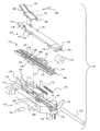
- FIG. 3depicts an exploded perspective view of the nose assembly of FIG. 2 ;
- FIG. 4depicts a partial side perspective view of the nose assembly of FIG. 2 without the base section showing the upper nose section lying on the lower nose section;
- FIG. 5depicts a partial side perspective view of the nose assembly of FIG. 2 without the base section showing the upper nose section in a locked coupled condition with the lower nose section and the spreading wedges of the lever positioned between opposing wedge walls of the lower nose section and the upper nose section;
- FIG. 6depicts a side plan view of the nose assembly of FIG. 2 as the upper nose section of the nose assembly contacts a work piece;
- FIG. 7depicts a side plan view of the nose assembly of FIG. 2 in a position whereat the angle between the upper arm of the lever and the upper surface of the upper nose section matches the angle defined by the ramps and the lower portion of the spreader such that the upper nose section and lower nose section have been received into an opening of the nose assembly spreader and the upper arm of the lever has come into contact with the ramps of the spreader as the nose assembly contacts a work piece, which causes a trigger disabling mechanism to be reconfigured;
- FIG. 8depicts a side plan view of the nose assembly of FIG. 2 wherein the angle between the upper arm of the lever and the upper surface of the upper nose section does not match the angle defined by the ramps of the spreader and the lower portion of the spreader, thereby inhibiting movement of the upper nose section and lower nose section into an opening of the nose assembly spreader so that the trigger disabling mechanism is not reconfigured.
- FIG. 1depicts a fastener impacting device 100 including a housing 102 and a fastener cartridge 104 .
- the housing 102defines a handle portion 106 from which a trigger 108 extends, a receptacle area 110 and a drive section 112 .
- the fastener cartridge 104in this embodiment is spring biased to force fasteners, such as nails or staples, serially one after the other, into a loaded position adjacent the drive section 112 .
- the receptacle area 110may be used to connect a source of compressed air or other source of power to the fastener impacting device 100 .
- the nose assembly 114Located adjacent to the drive portion 112 is a nose assembly 114 .
- the nose assembly 114includes a base 120 , a lower nose section 122 and an upper nose section 124 .
- the base 120includes a bed 126 shown in FIG. 3 .
- Two guide rails 128 and 130extend along the bed 126 and through an opening 132 defined in part by a spreader 134 .
- the spreader 134includes a lower portion 136 and a pair of ramps 138 which extend upwardly from the lower portion 136 and increase in height from the forward portion of the ramps 138 to the rear portion of the ramps 138 .
- a pair of spring wells 140are positioned at the bottom of the bed 126 and a pair of guide channels 142 (only one is sown in FIG. 2 ) are located adjacent to, and on the opposite sides of, the bed 126 .
- the lower nose section 122includes a number of forward facing wedges 144 and a pair of wedge walls 146 .
- a pair of guides 148 and a bracket 150are located at the sides of the lower nose section 122 .
- a spring stop 152is located on the bottom of the lower nose section 122 which may be shaped complementary to the guide rails 128 and 130 .
- the upper nose section 124includes a number of rearward facing wedges 154 and a pair of wedge walls 156 .
- a bracket 158is located on the upper surface of the rearward end portion 160 of the upper nose section 124 .
- the forward end portion 162defines a channel port 164 .
- the remaining components of the nose assembly 114 shown in FIG. 3are identified with reference to assembly of the nose assembly 114 .
- two springs 170are positioned in the spring wells 140 .
- the lower nose section 122is then placed on the bed 126 by aligning one of the guides 148 with a slot 172 .
- a depth control nut 174is positioned within the bracket 150 and a guide rod 176 is inserted through a first guide bore 178 , the bracket 150 , and the depth control nut 174 and into a second guide bore 180 .
- the guides 148are aligned with the guide channels 142 .
- the lower nose section 122is then moved slightly rearwardly (toward the ramps 138 ) which brings the spring stop 152 into contact with the springs 170 . Additionally, one of the guides 148 moves partially into one of the guide channels 142 . Insertion of the pin 182 into the pin hole 184 prevents the lower nose section 122 from moving forwardly to a location whereat the guide 148 nearest to the pin would no longer be within the guide channel 142 and aligned with the slot 172 . With the exception of the biasing force of the springs 170 , however, the lower nose section 122 is free to move rearwardly into the opening 132 . Thus, the lower nose section 122 is slidingly maintained on the bed 126 by a guide 148 located within a guide channel 142 on one side and by the bracket 150 which is slidably constrained by the guide rod 176 on the other side.
- the upper nose section 124is coupled with the lower nose section 122 by generally aligning the wedge walls 146 with the wedge walls 156 . This allows the rearward facing wedges 154 to move past the forward facing wedges 144 so that the upper nose section 124 is fully supported by the lower nose section 122 as shown in FIG. 4 . Once the upper nose section 124 is placed upon the lower nose section 122 , the end portions of the upper nose section 124 and the lower nose section 122 located underneath the upper arm 192 define a cross section that is slightly smaller than the size of the opening 132 .
- the upper nose section 124may then be moved in the direction of the arrow 200 in FIG. 4 . This movement initiates a coupling between the rearward facing wedges 154 and the forward facing wedges 144 . Thus, the lower nose section 122 and the upper nose section 124 form a nose piece 198 . Additionally, a gap is generated between each opposing pair of the wedge walls 146 and the wedge walls 156 . Once sufficient gaps are present, the lever 188 , which is constantly biased to rotate in the clockwise direction as viewed in FIG. 4 , rotates the spreading wedges 196 into the gaps between the wedge walls 146 and the wedge walls 156 .
- the bias of the lever 188forces the wedge walls 146 and the wedge walls 156 farther apart, thereby providing additional coupling between the rearward facing wedges 154 and the forward facing wedges 144 as shown in FIG. 5 .
- the end portions 202 and 204 of the lower nose section 122 and the upper nose section 124respectively, define an opening, generally indicated by reference number 206 , to a channel defined by the lower nose section 122 and the upper nose section 124 which is aligned with, and opens to, the channel port 164 shown in FIG. 2 .
- FIGS. 1 , 3 and 5Operation of the fastener impacting device 100 is described with reference to FIGS. 1 , 3 and 5 .
- An operatorafter providing an energy source to the fastener impacting device 100 using the receptacle area 110 , grasps the handle 106 .
- the operatormoves the fastener impacting device 100 toward a work piece 210 shown in FIG. 6 by moving the fastener impacting device 100 in the direction of the arrow 212 .
- Initial contact with the work piece 210is made by the upper nose section 124 .
- Continued application of pressureforces the springs 170 against the spring stop 152 (see FIG. 3 ) generating a bias of the lower nose section 120 in a direction toward the work piece 210 .
- Biasing of the lower nose section 120forces the rearward facing wedges 154 and the forward facing wedges 144 (see FIG. 5 ) toward a tighter coupling since the upper nose section 124 is immobilized by the work piece 210 .
- the base 120moves toward the work piece 210 , causing relative movement between the lower nose section 122 and the bed 126 .
- the nose piece 198 formed by the coupled lower nose section 122 and upper nose section 124is received more deeply into the opening 132 .
- the spreading wedges 196are rotated into the gap between the opposing wedge walls 146 and 156 such that the upper arm 192 is pivoted to an angle with respect to the upper surface of the upper nose section 124 which allows the nose piece 198 to extend through the opening 132 to cause reconfiguration of a trigger disabling mechanism to a condition which allows the trigger 108 to initiate a firing sequence.
- the trigger disabling mechanismmay be mechanically repositioned by the nose piece 198 .
- a signal indicative of the position of one or more of the movable portions of the nose assembly 114may be used to control reconfiguration of the trigger disabling mechanism.
- the trigger disabling mechanismelectrically disables the trigger 108 .
- the nose piece 198can be positioned with respect to the base 120 such that the trigger disabling mechanism enables initiation of a firing sequence by the trigger 108 .
- the operatorinitiates a firing sequence to impact a fastener by activating the trigger 108 .
- a fasteneris driven along the channel defined by the lower nose section 122 and the upper nose section 124 .
- the fasteneris then driven through the channel port 164 and into the work piece 210 .
- the depth to which the fastener is driven into the work piece 210may be controlled by positioning of the depth control nut 174 .
- the operatormoves the fastener impacting device in a direction away from the work piece 210 . This removes the compressive pressure from the springs 170 which then force the nose piece 198 along the bed 126 to an extended position whereat initiation of a firing sequence by the trigger 108 is again inhibited.
- the upper nose section 124 and the lower nose section 122may not be in a locked coupled condition when the upper arm 192 contacts the ramps 138 . So long as the upper nose section 124 and the lower nose section 122 are coupled and the nose assembly 114 is not jammed, the additional force provided by the contact with the ramps 138 can force the upper nose section 124 and the lower nose section 122 into a locked coupled condition.
- the spreading wedges 196will not be able to force the upper nose section 124 and the lower nose section 122 into a locked coupled condition. Accordingly, the angle formed between the upper arm 192 and the upper surface of the upper nose section 124 will be less than the angle defined by the ramps 138 and the lower portion 136 of the spreader 134 as depicted in FIG. 8 .
- the nose assembly 114may be disassembled to clear a fastener which is stuck in the channel between the lower nose section 122 and the upper nose section 124 . Disassembly of the nose assembly 114 is accomplished by first depressing the upper arm 192 of the lever 188 . As the upper arm 192 is moved toward the upper surface of the upper nose section 124 , the spreading wedges 196 are pivoted out of the gap between the opposing wedge walls 146 and 156 .
- the upper nose section 124is forced in a direction away from the ramps 138 .
- movement of the lower nose section 122 in the direction away from the ramps 138is inhibited by the pin 182 , which may be in the form of a screw or other removable component.
- the pin 182may be in the form of a screw or other removable component.
- continued movement of the upper nose section 124causes the rearward facing wedges 154 and the forward facing wedges 146 to de-couple.
- the upper nose section 124may then be lifted off of the lower nose section 122 to clear the nose assembly 114 .
Landscapes
- Engineering & Computer Science (AREA)
- Mechanical Engineering (AREA)
- Portable Nailing Machines And Staplers (AREA)
Abstract
Description
Claims (17)
Priority Applications (4)
| Application Number | Priority Date | Filing Date | Title |
|---|---|---|---|
| US12/235,848US7922054B2 (en) | 2008-09-23 | 2008-09-23 | Nail gun with integrated safety device |
| TW098130897ATWI600509B (en) | 2008-09-23 | 2009-09-14 | Nail gun with integrated safety device and method for impacting a fastener |
| AT09171099TATE553887T1 (en) | 2008-09-23 | 2009-09-23 | NAIL GUN WITH INTEGRATED SAFETY DEVICE |
| EP09171099AEP2165806B1 (en) | 2008-09-23 | 2009-09-23 | Nail gun with integrated safety device |
Applications Claiming Priority (1)
| Application Number | Priority Date | Filing Date | Title |
|---|---|---|---|
| US12/235,848US7922054B2 (en) | 2008-09-23 | 2008-09-23 | Nail gun with integrated safety device |
Publications (2)
| Publication Number | Publication Date |
|---|---|
| US20100072247A1 US20100072247A1 (en) | 2010-03-25 |
| US7922054B2true US7922054B2 (en) | 2011-04-12 |
Family
ID=41382178
Family Applications (1)
| Application Number | Title | Priority Date | Filing Date |
|---|---|---|---|
| US12/235,848Active2029-04-03US7922054B2 (en) | 2008-09-23 | 2008-09-23 | Nail gun with integrated safety device |
Country Status (4)
| Country | Link |
|---|---|
| US (1) | US7922054B2 (en) |
| EP (1) | EP2165806B1 (en) |
| AT (1) | ATE553887T1 (en) |
| TW (1) | TWI600509B (en) |
Cited By (11)
| Publication number | Priority date | Publication date | Assignee | Title |
|---|---|---|---|---|
| US20110132958A1 (en)* | 2009-12-04 | 2011-06-09 | Credo Technology Corporation | Fastening tool with releasable work contact element |
| US20120006878A1 (en)* | 2009-01-08 | 2012-01-12 | Illinois Tool Works Inc. | Device for setting fasteners |
| US20120085806A1 (en)* | 2010-10-12 | 2012-04-12 | Stanley Fastening Systems, L.P. | Dry fire lockout with bypass for fastener driving device |
| WO2014029796A2 (en) | 2012-08-24 | 2014-02-27 | Hilti Aktiengesellschaft | Hand-held tool |
| US10173310B2 (en) | 2015-02-06 | 2019-01-08 | Milwaukee Electric Tool Corporation | Gas spring-powered fastener driver |
| US20200016731A1 (en)* | 2018-07-16 | 2020-01-16 | Testo Industry Corp. | Quick release device for a panel of nail guns |
| US10576616B2 (en) | 2018-05-07 | 2020-03-03 | Black & Decker Inc. | Power tool wire form hook assembly |
| US10766127B2 (en) | 2018-05-07 | 2020-09-08 | Black & Decker Inc. | Nosepiece assembly with a passage for ejecting debris |
| US11123850B2 (en) | 2016-06-30 | 2021-09-21 | Black & Decker Inc. | Cordless concrete nailer with removable lower contact trip |
| US12179325B2 (en) | 2022-02-18 | 2024-12-31 | Milwaukee Electric Tool Corporation | Powered fastener driver |
| US12434367B2 (en) | 2022-03-04 | 2025-10-07 | Milwaukee Electric Tool Corporation | Powered fastener driver |
Families Citing this family (2)
| Publication number | Priority date | Publication date | Assignee | Title |
|---|---|---|---|---|
| US7913889B2 (en)* | 2009-07-22 | 2011-03-29 | Campbell Hausfeld/Scott Fetzer Company | Automatic quick clear nose for nailer |
| CN113618678B (en)* | 2020-05-06 | 2022-05-10 | 丰民金属工业股份有限公司 | Electric nail gun |
Citations (35)
| Publication number | Priority date | Publication date | Assignee | Title |
|---|---|---|---|---|
| US3011169A (en) | 1957-06-14 | 1961-12-05 | Reich Maschf Gmbh Karl | Nailing apparatus |
| US3273777A (en) | 1964-03-11 | 1966-09-20 | Senco Products | Easy clear guide body |
| US3570738A (en)* | 1967-11-24 | 1971-03-16 | Richard W Pabich | Tool for applying fasteners |
| US4121745A (en) | 1977-06-28 | 1978-10-24 | Senco Products, Inc. | Electro-mechanical impact device |
| US4197974A (en)* | 1978-06-12 | 1980-04-15 | Speedfast Corporation | Nailer |
| US4389012A (en)* | 1981-04-22 | 1983-06-21 | Duo-Fast Corporation | Fastener tool loading assembly |
| US4404894A (en)* | 1980-08-27 | 1983-09-20 | Hilti Aktiengesellschaft | Valve trigger assembly for pneumatic nailer |
| US4405071A (en)* | 1981-09-14 | 1983-09-20 | Duo-Fast Corporation | Fastener driving tool |
| US4436236A (en) | 1982-03-22 | 1984-03-13 | Senco Products, Inc. | Front gate and latch assembly for the guide body of an industrial fastener driving tool |
| US4549681A (en) | 1983-10-01 | 1985-10-29 | Hitachi Koki Company, Ltd. | Power-driven tacker with safety device |
| US4629106A (en)* | 1985-05-29 | 1986-12-16 | Signode Corporation | Actuating means for fastener driving tool |
| US4821937A (en)* | 1987-09-14 | 1989-04-18 | Duo-Fast Corporation | Guide for fastener driving tool |
| US5261587A (en)* | 1993-01-04 | 1993-11-16 | Illinois Tool Works Inc. | Fastener-driving tool with improved, adjustable, tool-actuating structures |
| US5350103A (en)* | 1993-07-13 | 1994-09-27 | Umberto Monacelli | Easy fastener jam removal tool |
| US5642849A (en) | 1995-12-01 | 1997-07-01 | Lih Jie Industrial Co., Ltd. | Barrel unit with a removable cover plate for a nail driving gun |
| US5649660A (en)* | 1993-09-22 | 1997-07-22 | Hitachi Koki Co., Ltd. | Nail gun having sharpshooting tapered end |
| US5662257A (en)* | 1994-03-11 | 1997-09-02 | Makita Corporation | Nailing machine |
| US5862969A (en)* | 1997-09-17 | 1999-01-26 | De Poan Pneumatic Corporation | Safety trigger for nailer |
| US6209770B1 (en)* | 1999-04-05 | 2001-04-03 | Stanley Fastening Systems, Lp | Safety trip assembly and trip lock mechanism for a fastener driving tool |
| US6318618B1 (en) | 2000-12-26 | 2001-11-20 | Apach Industrial Co., Ltd. | Barrel unit with a removable cover plate for a pneumatic nail driving device |
| US6427896B1 (en)* | 2002-01-25 | 2002-08-06 | Roman Ho | Safety device for pneumatic nailers |
| US6592014B2 (en)* | 2001-12-13 | 2003-07-15 | Illinois Tool Works Inc. | Lockout mechanism for fastener driving tool |
| US20040084499A1 (en) | 2002-11-04 | 2004-05-06 | Chien-Fang Tsai | Pneumatic nailing machine |
| US6763989B2 (en) | 2001-08-31 | 2004-07-20 | Kuan Lin Wang | Slidable nozzle for power nailers |
| US6908021B1 (en)* | 2004-02-04 | 2005-06-21 | Nailermate Enterprise Corp. | Safety catch mechanism of nail guns |
| US6929165B1 (en)* | 2004-08-04 | 2005-08-16 | Rexon Industrial Corp., Ltd. | Pneumatic nail gun |
| US20060191973A1 (en) | 2005-02-25 | 2006-08-31 | Basso Industry Corp. | Nail stopper for a skew nailing gun |
| US7143918B2 (en)* | 2003-07-30 | 2006-12-05 | Stanley Fastening Systems, L.P. | Fastener driving device with automatic dual-mode trigger assembly |
| US7413103B1 (en)* | 2007-03-22 | 2008-08-19 | Apach Industrial Co., Ltd. | Dry firing prevention device for nail gun |
| US7458492B2 (en)* | 2004-02-20 | 2008-12-02 | Black & Decker Inc. | Dual mode pneumatic fastener actuation mechanism |
| US7464843B2 (en)* | 2007-02-06 | 2008-12-16 | De Poan Pneumatic Corp. | Trigger switch mechanism of nail gun |
| US7484647B2 (en)* | 2007-06-04 | 2009-02-03 | Testo Industry Corp. | Nail gun with a safety assembly |
| US7506787B2 (en)* | 2006-12-08 | 2009-03-24 | Basso Industry Corp. | Nail-driving device with safety unit |
| US20090108046A1 (en)* | 2007-10-24 | 2009-04-30 | Chi-Sheng Huang | Trigger Switch Mechanism for Nail Gun |
| US20090250498A1 (en)* | 2008-04-07 | 2009-10-08 | Basso Industry Corp. | Nail-driving device with safety unit |
Family Cites Families (3)
| Publication number | Priority date | Publication date | Assignee | Title |
|---|---|---|---|---|
| US5174485A (en)* | 1989-12-19 | 1992-12-29 | Duo-Fast Corporation | Fastener driving tool |
| US5193730A (en)* | 1991-06-14 | 1993-03-16 | Max Co., Ltd. | Pneumatic nailing machine |
| US6808101B2 (en)* | 2002-05-24 | 2004-10-26 | Illinois Tool Works Inc. | Framing tool with automatic fastener-size adjustment |
- 2008
- 2008-09-23USUS12/235,848patent/US7922054B2/enactiveActive
- 2009
- 2009-09-14TWTW098130897Apatent/TWI600509B/ennot_activeIP Right Cessation
- 2009-09-23ATAT09171099Tpatent/ATE553887T1/enactive
- 2009-09-23EPEP09171099Apatent/EP2165806B1/ennot_activeNot-in-force
Patent Citations (35)
| Publication number | Priority date | Publication date | Assignee | Title |
|---|---|---|---|---|
| US3011169A (en) | 1957-06-14 | 1961-12-05 | Reich Maschf Gmbh Karl | Nailing apparatus |
| US3273777A (en) | 1964-03-11 | 1966-09-20 | Senco Products | Easy clear guide body |
| US3570738A (en)* | 1967-11-24 | 1971-03-16 | Richard W Pabich | Tool for applying fasteners |
| US4121745A (en) | 1977-06-28 | 1978-10-24 | Senco Products, Inc. | Electro-mechanical impact device |
| US4197974A (en)* | 1978-06-12 | 1980-04-15 | Speedfast Corporation | Nailer |
| US4404894A (en)* | 1980-08-27 | 1983-09-20 | Hilti Aktiengesellschaft | Valve trigger assembly for pneumatic nailer |
| US4389012A (en)* | 1981-04-22 | 1983-06-21 | Duo-Fast Corporation | Fastener tool loading assembly |
| US4405071A (en)* | 1981-09-14 | 1983-09-20 | Duo-Fast Corporation | Fastener driving tool |
| US4436236A (en) | 1982-03-22 | 1984-03-13 | Senco Products, Inc. | Front gate and latch assembly for the guide body of an industrial fastener driving tool |
| US4549681A (en) | 1983-10-01 | 1985-10-29 | Hitachi Koki Company, Ltd. | Power-driven tacker with safety device |
| US4629106A (en)* | 1985-05-29 | 1986-12-16 | Signode Corporation | Actuating means for fastener driving tool |
| US4821937A (en)* | 1987-09-14 | 1989-04-18 | Duo-Fast Corporation | Guide for fastener driving tool |
| US5261587A (en)* | 1993-01-04 | 1993-11-16 | Illinois Tool Works Inc. | Fastener-driving tool with improved, adjustable, tool-actuating structures |
| US5350103A (en)* | 1993-07-13 | 1994-09-27 | Umberto Monacelli | Easy fastener jam removal tool |
| US5649660A (en)* | 1993-09-22 | 1997-07-22 | Hitachi Koki Co., Ltd. | Nail gun having sharpshooting tapered end |
| US5662257A (en)* | 1994-03-11 | 1997-09-02 | Makita Corporation | Nailing machine |
| US5642849A (en) | 1995-12-01 | 1997-07-01 | Lih Jie Industrial Co., Ltd. | Barrel unit with a removable cover plate for a nail driving gun |
| US5862969A (en)* | 1997-09-17 | 1999-01-26 | De Poan Pneumatic Corporation | Safety trigger for nailer |
| US6209770B1 (en)* | 1999-04-05 | 2001-04-03 | Stanley Fastening Systems, Lp | Safety trip assembly and trip lock mechanism for a fastener driving tool |
| US6318618B1 (en) | 2000-12-26 | 2001-11-20 | Apach Industrial Co., Ltd. | Barrel unit with a removable cover plate for a pneumatic nail driving device |
| US6763989B2 (en) | 2001-08-31 | 2004-07-20 | Kuan Lin Wang | Slidable nozzle for power nailers |
| US6592014B2 (en)* | 2001-12-13 | 2003-07-15 | Illinois Tool Works Inc. | Lockout mechanism for fastener driving tool |
| US6427896B1 (en)* | 2002-01-25 | 2002-08-06 | Roman Ho | Safety device for pneumatic nailers |
| US20040084499A1 (en) | 2002-11-04 | 2004-05-06 | Chien-Fang Tsai | Pneumatic nailing machine |
| US7143918B2 (en)* | 2003-07-30 | 2006-12-05 | Stanley Fastening Systems, L.P. | Fastener driving device with automatic dual-mode trigger assembly |
| US6908021B1 (en)* | 2004-02-04 | 2005-06-21 | Nailermate Enterprise Corp. | Safety catch mechanism of nail guns |
| US7458492B2 (en)* | 2004-02-20 | 2008-12-02 | Black & Decker Inc. | Dual mode pneumatic fastener actuation mechanism |
| US6929165B1 (en)* | 2004-08-04 | 2005-08-16 | Rexon Industrial Corp., Ltd. | Pneumatic nail gun |
| US20060191973A1 (en) | 2005-02-25 | 2006-08-31 | Basso Industry Corp. | Nail stopper for a skew nailing gun |
| US7506787B2 (en)* | 2006-12-08 | 2009-03-24 | Basso Industry Corp. | Nail-driving device with safety unit |
| US7464843B2 (en)* | 2007-02-06 | 2008-12-16 | De Poan Pneumatic Corp. | Trigger switch mechanism of nail gun |
| US7413103B1 (en)* | 2007-03-22 | 2008-08-19 | Apach Industrial Co., Ltd. | Dry firing prevention device for nail gun |
| US7484647B2 (en)* | 2007-06-04 | 2009-02-03 | Testo Industry Corp. | Nail gun with a safety assembly |
| US20090108046A1 (en)* | 2007-10-24 | 2009-04-30 | Chi-Sheng Huang | Trigger Switch Mechanism for Nail Gun |
| US20090250498A1 (en)* | 2008-04-07 | 2009-10-08 | Basso Industry Corp. | Nail-driving device with safety unit |
Cited By (23)
| Publication number | Priority date | Publication date | Assignee | Title |
|---|---|---|---|---|
| US20120006878A1 (en)* | 2009-01-08 | 2012-01-12 | Illinois Tool Works Inc. | Device for setting fasteners |
| US8960518B2 (en)* | 2009-01-08 | 2015-02-24 | Illinois Tool Works Inc. | Device for setting fasteners |
| US20110132958A1 (en)* | 2009-12-04 | 2011-06-09 | Credo Technology Corporation | Fastening tool with releasable work contact element |
| US8146788B2 (en)* | 2009-12-04 | 2012-04-03 | Robert Bosch Gmbh | Fastening tool with releasable work contact element |
| US20120085806A1 (en)* | 2010-10-12 | 2012-04-12 | Stanley Fastening Systems, L.P. | Dry fire lockout with bypass for fastener driving device |
| US8292143B2 (en)* | 2010-10-12 | 2012-10-23 | Stanley Fastening Systems, L.P. | Dry fire lockout with bypass for fastener driving device |
| WO2014029796A2 (en) | 2012-08-24 | 2014-02-27 | Hilti Aktiengesellschaft | Hand-held tool |
| DE102012215126A1 (en) | 2012-08-24 | 2014-05-28 | Hilti Aktiengesellschaft | Hand-held implement |
| US20150298307A1 (en)* | 2012-08-24 | 2015-10-22 | Hilti Aktiengesellschaft | Hand-held tool |
| US10118283B2 (en)* | 2012-08-24 | 2018-11-06 | Hilti Aktiengesellschaft | Hand-held tool |
| US10173310B2 (en) | 2015-02-06 | 2019-01-08 | Milwaukee Electric Tool Corporation | Gas spring-powered fastener driver |
| US11072058B2 (en) | 2015-02-06 | 2021-07-27 | Milwaukee Electric Tool Corporation | Gas spring-powered fastener driver |
| US11633842B2 (en) | 2015-02-06 | 2023-04-25 | Milwaukee Electric Tool Corporation | Gas spring-powered fastener driver |
| US11926028B2 (en) | 2015-02-06 | 2024-03-12 | Milwaukee Electric Tool Corporation | Gas spring-powered fastener driver |
| US12103152B2 (en) | 2015-02-06 | 2024-10-01 | Milwaukee Electric Tool Corporation | Gas spring-powered fastener driver |
| US12420394B2 (en) | 2015-02-06 | 2025-09-23 | Milwaukee Electric Tool Corporation | Gas spring-powered fastener driver |
| US11123850B2 (en) | 2016-06-30 | 2021-09-21 | Black & Decker Inc. | Cordless concrete nailer with removable lower contact trip |
| US10576616B2 (en) | 2018-05-07 | 2020-03-03 | Black & Decker Inc. | Power tool wire form hook assembly |
| US10766127B2 (en) | 2018-05-07 | 2020-09-08 | Black & Decker Inc. | Nosepiece assembly with a passage for ejecting debris |
| US20200016731A1 (en)* | 2018-07-16 | 2020-01-16 | Testo Industry Corp. | Quick release device for a panel of nail guns |
| US10807223B2 (en)* | 2018-07-16 | 2020-10-20 | Testo Industry Corp. | Quick release device for a panel of nail guns |
| US12179325B2 (en) | 2022-02-18 | 2024-12-31 | Milwaukee Electric Tool Corporation | Powered fastener driver |
| US12434367B2 (en) | 2022-03-04 | 2025-10-07 | Milwaukee Electric Tool Corporation | Powered fastener driver |
Also Published As
| Publication number | Publication date |
|---|---|
| TW201016409A (en) | 2010-05-01 |
| US20100072247A1 (en) | 2010-03-25 |
| EP2165806A2 (en) | 2010-03-24 |
| TWI600509B (en) | 2017-10-01 |
| EP2165806A3 (en) | 2011-03-09 |
| EP2165806B1 (en) | 2012-04-18 |
| ATE553887T1 (en) | 2012-05-15 |
Similar Documents
| Publication | Publication Date | Title |
|---|---|---|
| US7922054B2 (en) | Nail gun with integrated safety device | |
| CA2422447C (en) | Framing tool with automatic fastener-size adjustment | |
| EP1621291B1 (en) | Nail drive guide mechanism in nailing machine | |
| US7882994B2 (en) | 45 degree adjustable adapter for flooring nailer | |
| JP2541323Y2 (en) | Nail jam removal device for nailing machine | |
| US2918675A (en) | Dimpling and depth controlling attachment for fastening member driving tools | |
| KR100778930B1 (en) | Tableting device with improved safety measures | |
| US9573260B2 (en) | Fastening device for driving double-headed fasteners | |
| US20060091178A1 (en) | Positioning structure for nailer | |
| CA2531366A1 (en) | Power-driven nailing machine | |
| US20070114259A1 (en) | Multi-blow pneumatic hand tool for inserting t-nuts | |
| WO2007072785A1 (en) | Nailing machine | |
| US20080105726A1 (en) | Vertical feed hand stapler | |
| US20230081815A1 (en) | Protective Support Structure for Nailer | |
| US20060219749A1 (en) | Safety control pin for controlling a push plate to activate pneumatic switch of pneumatic staplers | |
| KR100401445B1 (en) | Fastening apparatus and fastening pin for wooden floor panel | |
| JP2004050375A (en) | Mechanism for guiding contact member of nailing machine |
Legal Events
| Date | Code | Title | Description |
|---|---|---|---|
| AS | Assignment | Owner name:CREDO TECHNOLOGY CORPORATION,ILLINOIS Free format text:ASSIGNMENT OF ASSIGNORS INTEREST;ASSIGNOR:COLE, JR., STEVEN WYNNE;REEL/FRAME:021571/0283 Effective date:20080919 Owner name:ROBERT BOSCH GMBH,GERMANY Free format text:ASSIGNMENT OF ASSIGNORS INTEREST;ASSIGNOR:COLE, JR., STEVEN WYNNE;REEL/FRAME:021571/0283 Effective date:20080919 Owner name:CREDO TECHNOLOGY CORPORATION, ILLINOIS Free format text:ASSIGNMENT OF ASSIGNORS INTEREST;ASSIGNOR:COLE, JR., STEVEN WYNNE;REEL/FRAME:021571/0283 Effective date:20080919 Owner name:ROBERT BOSCH GMBH, GERMANY Free format text:ASSIGNMENT OF ASSIGNORS INTEREST;ASSIGNOR:COLE, JR., STEVEN WYNNE;REEL/FRAME:021571/0283 Effective date:20080919 | |
| STCF | Information on status: patent grant | Free format text:PATENTED CASE | |
| FPAY | Fee payment | Year of fee payment:4 | |
| MAFP | Maintenance fee payment | Free format text:PAYMENT OF MAINTENANCE FEE, 8TH YEAR, LARGE ENTITY (ORIGINAL EVENT CODE: M1552); ENTITY STATUS OF PATENT OWNER: LARGE ENTITY Year of fee payment:8 | |
| MAFP | Maintenance fee payment | Free format text:PAYMENT OF MAINTENANCE FEE, 12TH YEAR, LARGE ENTITY (ORIGINAL EVENT CODE: M1553); ENTITY STATUS OF PATENT OWNER: LARGE ENTITY Year of fee payment:12 |