US7921750B2 - Power tong frames - Google Patents
Power tong framesDownload PDFInfo
- Publication number
- US7921750B2 US7921750B2US10/432,059US43205903AUS7921750B2US 7921750 B2US7921750 B2US 7921750B2US 43205903 AUS43205903 AUS 43205903AUS 7921750 B2US7921750 B2US 7921750B2
- Authority
- US
- United States
- Prior art keywords
- frame
- tong
- seat
- support unit
- tong assembly
- Prior art date
- Legal status (The legal status is an assumption and is not a legal conclusion. Google has not performed a legal analysis and makes no representation as to the accuracy of the status listed.)
- Expired - Fee Related
Links
Images


Classifications
- E—FIXED CONSTRUCTIONS
- E21—EARTH OR ROCK DRILLING; MINING
- E21B—EARTH OR ROCK DRILLING; OBTAINING OIL, GAS, WATER, SOLUBLE OR MELTABLE MATERIALS OR A SLURRY OF MINERALS FROM WELLS
- E21B19/00—Handling rods, casings, tubes or the like outside the borehole, e.g. in the derrick; Apparatus for feeding the rods or cables
- E21B19/16—Connecting or disconnecting pipe couplings or joints
- E21B19/161—Connecting or disconnecting pipe couplings or joints using a wrench or a spinner adapted to engage a circular section of pipe
- E21B19/164—Connecting or disconnecting pipe couplings or joints using a wrench or a spinner adapted to engage a circular section of pipe motor actuated
- E—FIXED CONSTRUCTIONS
- E21—EARTH OR ROCK DRILLING; MINING
- E21B—EARTH OR ROCK DRILLING; OBTAINING OIL, GAS, WATER, SOLUBLE OR MELTABLE MATERIALS OR A SLURRY OF MINERALS FROM WELLS
- E21B19/00—Handling rods, casings, tubes or the like outside the borehole, e.g. in the derrick; Apparatus for feeding the rods or cables
- E21B19/16—Connecting or disconnecting pipe couplings or joints
Definitions
- This inventionrelates to power tong frames.
- a power tongto torque the connection up to a predetermined torque in order to make this connection.
- the power tongis located on the platform, either on rails, or hung from a derrick on a chain.
- An active (or wrenching) tongsupplies torque to the section of tubular above the threaded connection, while a passive (or back up) tong supplies a reaction torque below the threaded connection.
- the back up tongclamps the tubular below the threaded connection, and prevents it from rotating. This clamping can be performed mechanically, hydraulically or pneumatically.
- the wrenching tongclamps the upper part of the connection and is driven so that it supplies torque for a limited angle.
- This power tong arrangementis also used to torque up connections between other tubulars, for example sections of casing and tubing.
- power tongsincluding the two tong arrangement described above and other commercially available tongs are suspended by chains from a crane or other support.
- chainscan get in the way of other equipment, for example drill pipe spinners which are used to run in a threaded connection between sections of pipe prior to a final tightening of the connection with the wrenching and backup tongs.
- apparatus for securing a joint between two lengths of tubularcomprising:
- a tong arrangementcomprising a rotary tong and a back-up tong
- rigid support meanscoupled to the frame for supporting the tong arrangement such that the arrangement can be oriented in use at an angle to the longitudinal axis of the frame;
- said rigid support meanscomprises a seat for supporting the tong arrangement from beneath.
- the tong arrangementis supported on the seat such that the arrangement is able to move with respect to the seat in a substantially transverse plane, relative to the axis of the tubulars.
- said seatcomprises means for tending to return the tong arrangement to a central position following deflection of the tong arrangement from that central position.
- the tong arrangementrests upon two or more support points of the seat.
- the support points, and/or the respective contact members on the tong arrangement which contact the support pointseach comprise a resilient member which provides a mechanism for tending to return the tong arrangement to a centre position following deflection of the tong.
- the resilient membersmay be of rubber or synthetic rubber, or may be helical or wound springs.
- said seatis substantially “V” shaped and lies in use in a substantially horizontal plane.
- Respective support pointsare located at the end of each leg of the seat and each comprises a part of a sphere or a spherical recess formed in a base member.
- Complimentary shaped parts or recessesare provided on the base of the tong arrangement for engagement with the support points on the seat.
- the radii of the part sphere and recessdiffer to allow relative transverse displacement of the tong arrangement and the seat.
- the part spherical members or the base members in which the spherical recesses are formedare supported on resilient members to provide suspension for the tong arrangement.
- the tong arrangementis coupled to the frame, above said seat, by an elongate alignment member having a variable length.
- the orientation of the tong arrangementmay be varied by varying the length of said elongate member.
- the membercomprises a hydraulically or pneumatically operated telescopic rod.
- the membermay be a chain.
- said seatis movable up and down said frame in order to allow the tong arrangement to be moved up and down.
- a frame for supporting a tong arrangementcomprising a rotary tong and a backup tong, the frame comprising:
- said rigid support meanscomprises a seat for supporting the tong arrangement from beneath.
- apparatus for securing a joint between two lengths of tubularcomprising:
- a tong arrangementcomprising a rotary tong and a back-up tong
- rigid support meanscoupled to the frame for supporting the tong arrangement such that the arrangement can move to a limited extent relative to the support means in a plane transverse to the longitudinal axis of the tubulars;
- a frame for supporting a tong arrangementcomprising a rotary tong and a backup tong, the frame comprising:
- rigid support meanscoupled to the frame for supporting the tong arrangement such that the arrangement can move to a limited extent relative to the support means in a plane transverse to the longitudinal axis of tubulars to be connected;
- FIG. 1is a view of an arrangement of a wrenching tong and a back-up tong
- FIG. 2is a side view of a frame for supporting the tong arrangement of FIG. 1 ;
- FIG. 3is a front view of the frame of FIG. 2 , with a wrenching tong in place;
- FIG. 4shows in more detail a support point of the frame of FIGS. 2 and 3 ;
- FIG. 5shows a side view of the frame of FIG. 2 , with a wrenching tong in place and tilted at an angle to the vertical.
- FIG. 1shows a power tong arrangement comprising a wrenching tong 1 and a back-up tong 11 .
- This arrangementis the subject of co-pending British patent application number 9927825.1 filed Nov. 26, 1999, and published as GB 2370246 on Jun. 26, 2002.
- the wrenching tong 1is generally in the form of a cylinder with an opening 2 through the centre thereof for receiving a stand of drill pipe (not shown), and a recess 3 running from the edge to the opening 2 at the centre.
- the back-up tong 11is located beneath the wrenching tong 1 .
- the back-up tongis generally in the form of a disc with similar dimensions to the wrenching tong 1 .
- the back-up tongis also provided with an opening 12 through the centre and a recess 13 from the edge to the opening at the centre.
- the opening 12 and recess 13correspond to the opening 2 and recess 3 of the wrenching tong when the back-up tong 11 and the wrenching tong 1 are correctly aligned.
- a plurality of guide rollers 10 or other guide elementsare spaced around the edge of the wrenching tong 1 in order to maintain the alignment of the wrenching tong 1 with the back-up tong 11 .
- the back-up tong 11is provided with two pinion drives 4 arranged opposite each other at the periphery of the disc, equally spaced either side of the opening 12 .
- Each pinion drivecomprises a drive motor 5 , drive shaft (not shown) and pinion (hidden in FIG. 1 but indicated generally by the numeral 7 ) attached to the drive shaft.
- a gear 14is provided around the periphery of the wrenching tong 1 , broken by the recess 3 .
- the gear 14meshes with the pinions attached to the motors 5 on the back-up tong, so that when the drive motors 5 drive the drive shafts and pinions 7 , the wrenching tong 1 rotates relative to the back-up tong 11 .
- the angle of rotationis limited by the recess 3 of the wrenching tong 1 .
- Three clamping jawsare located inside each of the wrenching tong 1 and back-up tong 11 as illustrated in FIG. 1 . These are hydraulically driven for clamping the drill pipe stand in place in the centre of the wrenching tong.
- the hydraulic power supplymay be provided by hoses (not shown).
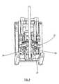
- FIG. 2illustrates a frame 20 for supporting a tong arrangement.
- the frame 20comprises a “V” shaped seat 21 which lies in a horizontal plane and can be raised and lowered relative to the frame upright section 22 .
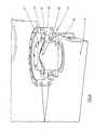
- FIG. 3illustrates a tong arrangement 23 , such as that described with reference to FIG. 1 , located in the frame 20 and supported on the seat 21 so that substantially all of the weight of the tong arrangement 23 is borne by the frame 20 via the seat 21 .
- Each support unit 24comprises a bearing 25 having a part spherical upper portion 26 .
- a base member 27In contact with the part spherical portion 26 is a base member 27 having a spherically shaped recess 28 formed therein.
- a flange 29is secured to the base member 27 and rests upon an annular rubber member 30 which surrounds the bearing 25 .
- the base members 27are secured to the base of the tong arrangement 23 .
- the base member 27is at all times in contact with the top of the bearing 25 .
- the rubber member 30is compressed on one side by the weight of the tong arrangement.
- the reaction force produced by the member 30 on the tong arrangementtends to push the tong arrangement back to its central position.
- the support mechanismcomprising the seat 21 and the support units 24 helps to secure the tong arrangement against the effects of vibrations whilst the wrenching tong is rotating.
- the radius of the spherical recess 28is greater than that of the spherical portion 26 on which it is supported.
- the dimensions of the various componentsare such as to allow several centimeters of relative movement such as is required during the gripping of a drill pipe in order to avoid problems which will arise when the frame is not correctly aligned with the drill pipe.
- the ability of the tong arrangement to “float” above the seatalso prevents damage resulting from movement of the backup tong during operation of the tong arrangement.
- FIG. 5illustrates the frame 20 of FIGS. 2 to 4 , with the tong arrangement 23 being coupled to an upright member 31 , which is attached to the seat 21 at right angles thereto.
- the upright member 31moves up and down in the frame 20 with the seat 21 .
- the tong arrangement 23is coupled to the upright member 31 by a hydraulically or pneumatically driven rod 32 .
- the rod 32is coupled at its ends to the tong arrangement 23 and the upright member 31 by respective pivotable joints. By extending and retracting the rod 32 , it is possible to vary the alignment of the tong arrangement 23 with respect to the vertical axis and to hold the tong arrangement in the desired position against the reaction force of the rubber member 30 .
- the tong arrangementwill return to its central position.
- the frame of FIGS. 2 to 5is suitable for use in situations where the well being drilled is at an angle to the vertical.
- the overall height of the frameis reduced compared to conventional frames.
- the tong arrangementmay be held by some other rigid support means which grips or is attached to the sides or top of the tong arrangement.
Landscapes
- Engineering & Computer Science (AREA)
- Geology (AREA)
- Mining & Mineral Resources (AREA)
- Life Sciences & Earth Sciences (AREA)
- General Life Sciences & Earth Sciences (AREA)
- Fluid Mechanics (AREA)
- Environmental & Geological Engineering (AREA)
- Physics & Mathematics (AREA)
- Mechanical Engineering (AREA)
- Geochemistry & Mineralogy (AREA)
- Earth Drilling (AREA)
- Supports For Pipes And Cables (AREA)
- Automatic Assembly (AREA)
- Pivots And Pivotal Connections (AREA)
- Accommodation For Nursing Or Treatment Tables (AREA)
- Chairs Characterized By Structure (AREA)
Abstract
Description
Claims (46)
Applications Claiming Priority (3)
| Application Number | Priority Date | Filing Date | Title |
|---|---|---|---|
| GB0028313.5 | 2000-11-21 | ||
| GB0028313AGB2370246B (en) | 2000-11-21 | 2000-11-21 | Power tong frames |
| PCT/GB2001/005121WO2002042600A1 (en) | 2000-11-21 | 2001-11-19 | Power tong frames |
Publications (2)
| Publication Number | Publication Date |
|---|---|
| US20040035573A1 US20040035573A1 (en) | 2004-02-26 |
| US7921750B2true US7921750B2 (en) | 2011-04-12 |
Family
ID=9903540
Family Applications (1)
| Application Number | Title | Priority Date | Filing Date |
|---|---|---|---|
| US10/432,059Expired - Fee RelatedUS7921750B2 (en) | 2000-11-21 | 2001-11-19 | Power tong frames |
Country Status (7)
| Country | Link |
|---|---|
| US (1) | US7921750B2 (en) |
| EP (1) | EP1336026B1 (en) |
| AU (1) | AU2002223080A1 (en) |
| CA (1) | CA2428554C (en) |
| GB (1) | GB2370246B (en) |
| NO (1) | NO334990B1 (en) |
| WO (1) | WO2002042600A1 (en) |
Cited By (8)
| Publication number | Priority date | Publication date | Assignee | Title |
|---|---|---|---|---|
| US20110214917A1 (en)* | 2009-09-12 | 2011-09-08 | Professional Wireline Rentals, Llc | Power Swivel Stand Having Pivoting Positioning Arms |
| US20110219916A1 (en)* | 2008-10-14 | 2011-09-15 | Per Olav Haughom | Power Tong Device |
| US20110252926A1 (en)* | 2010-04-15 | 2011-10-20 | Eglin John J | Floating wrench assembly for drill rig |
| US20120312128A1 (en)* | 2011-06-07 | 2012-12-13 | Feigel Kurt R Jr | Tong assemblies |
| US9964370B2 (en) | 2015-03-26 | 2018-05-08 | American Defense Manufacturing, Llc | Ambidextrously Operable Firearm Receiver Assembly |
| US10081991B2 (en) | 2014-11-05 | 2018-09-25 | Weatherford Technology Holdings, Llc | Modular adapter for tongs |
| US11454069B2 (en) | 2020-04-21 | 2022-09-27 | Schlumberger Technology Corporation | System and method for handling a tubular member |
| US11585184B1 (en)* | 2020-08-25 | 2023-02-21 | Agi Industries, Inc. | Method and apparatus for positioning of injector heads and other intervention equipment |
Families Citing this family (5)
| Publication number | Priority date | Publication date | Assignee | Title |
|---|---|---|---|---|
| GB2348844A (en) | 1999-04-13 | 2000-10-18 | Weatherford Lamb | Apparatus and method for aligning tubulars |
| US7281451B2 (en)* | 2002-02-12 | 2007-10-16 | Weatherford/Lamb, Inc. | Tong |
| US7506564B2 (en) | 2002-02-12 | 2009-03-24 | Weatherford/Lamb, Inc. | Gripping system for a tong |
| US20060053977A1 (en)* | 2004-09-16 | 2006-03-16 | Hawkins Samuel P Iii | Apparatus and method for assembling and disassembling downhole components in a horizontal mode |
| US10648255B2 (en)* | 2018-03-09 | 2020-05-12 | Weatherford Technology Holdings, Llc | Tubular stabbing guide for tong assembly |
Citations (23)
| Publication number | Priority date | Publication date | Assignee | Title |
|---|---|---|---|---|
| US2668689A (en) | 1947-11-07 | 1954-02-09 | C & C Tool Corp | Automatic power tongs |
| US3288000A (en) | 1965-01-28 | 1966-11-29 | Foster James Lewis | Supporting and positioning mechanism for power tongs |
| US3803953A (en) | 1972-03-01 | 1974-04-16 | Byron Jackson Inc | Orienting apparatus for threaded well pipe |
| US3857451A (en) | 1973-03-15 | 1974-12-31 | Robbins Co | Invertible drilling machine |
| US3902561A (en)* | 1973-05-08 | 1975-09-02 | Atlas Copco Ab | Device particularly intended for long-hole drilling at driving of raises or the like |
| GB2009705A (en) | 1977-06-25 | 1979-06-20 | Swanson R | Load handling grapple for rotating load |
| WO1982000428A1 (en) | 1980-07-31 | 1982-02-18 | Varco Int | Well pipe connecting and disconnecting apparatus |
| US4445403A (en)* | 1982-03-29 | 1984-05-01 | Larry D. Kliewer | Power tongs |
| US4581956A (en)* | 1983-01-28 | 1986-04-15 | Kley-France | Screwing-unscrewing apparatus, more especially for screwing the stud-bolts fixing the lid of the reactor vessel of a nuclear reactor |
| US4727781A (en)* | 1985-04-17 | 1988-03-01 | The Science & Technic Department of Dagang Petroleum Administration | Supercharged power tongs |
| US4734081A (en)* | 1985-11-04 | 1988-03-29 | Bell Helicopter Textron Inc. | Constant velocity elastomeric bearing joint |
| GB2201912A (en) | 1987-03-09 | 1988-09-14 | Armco Inc | Apparatus for making and breaking well pipe connections |
| US5060542A (en)* | 1990-10-12 | 1991-10-29 | Hawk Industries, Inc. | Apparatus and method for making and breaking joints in drill pipe strings |
| WO1993018276A1 (en) | 1992-03-11 | 1993-09-16 | Weatherford/Lamb, Inc. | Automatic torque wrenching machine |
| US5297874A (en) | 1990-01-06 | 1994-03-29 | Dunlop Limited, A British Company | Elastomeric bearing |
| US5495782A (en)* | 1993-05-06 | 1996-03-05 | Paul-Heinz Wagner | Power wrench |
| WO1998032948A1 (en) | 1997-01-29 | 1998-07-30 | Weatherford/Lamb, Inc. | Apparatus and method for aligning tubulars |
| US5791206A (en)* | 1996-12-10 | 1998-08-11 | Ingersoll-Rand Company | Drill pipe handling mechanism |
| US5868045A (en)* | 1993-05-26 | 1999-02-09 | Hawk Industries, Inc. | Apparatus for making and breaking joints in drill pipe strings |
| US5931231A (en)* | 1996-06-27 | 1999-08-03 | Bucyrus International, Inc. | Blast hole drill pipe gripping mechanism |
| US6142040A (en)* | 1999-06-11 | 2000-11-07 | Franks Casing Crew And Rental Tools, Inc. | Direct coupled tong and spider |
| US6142041A (en)* | 1998-12-01 | 2000-11-07 | Buck; David A. | Power tong support assembly |
| US6318214B1 (en)* | 1998-12-01 | 2001-11-20 | David A. Buck | Power tong positioning apparatus |
- 2000
- 2000-11-21GBGB0028313Apatent/GB2370246B/ennot_activeExpired - Fee Related
- 2001
- 2001-11-19AUAU2002223080Apatent/AU2002223080A1/ennot_activeAbandoned
- 2001-11-19WOPCT/GB2001/005121patent/WO2002042600A1/enactiveSearch and Examination
- 2001-11-19CACA2428554Apatent/CA2428554C/ennot_activeExpired - Fee Related
- 2001-11-19USUS10/432,059patent/US7921750B2/ennot_activeExpired - Fee Related
- 2001-11-19EPEP01997615.8Apatent/EP1336026B1/ennot_activeExpired - Lifetime
- 2003
- 2003-05-09NONO20032075Apatent/NO334990B1/ennot_activeIP Right Cessation
Patent Citations (25)
| Publication number | Priority date | Publication date | Assignee | Title |
|---|---|---|---|---|
| US2668689A (en) | 1947-11-07 | 1954-02-09 | C & C Tool Corp | Automatic power tongs |
| US3288000A (en) | 1965-01-28 | 1966-11-29 | Foster James Lewis | Supporting and positioning mechanism for power tongs |
| US3803953A (en) | 1972-03-01 | 1974-04-16 | Byron Jackson Inc | Orienting apparatus for threaded well pipe |
| US3857451A (en) | 1973-03-15 | 1974-12-31 | Robbins Co | Invertible drilling machine |
| US3902561A (en)* | 1973-05-08 | 1975-09-02 | Atlas Copco Ab | Device particularly intended for long-hole drilling at driving of raises or the like |
| GB2009705A (en) | 1977-06-25 | 1979-06-20 | Swanson R | Load handling grapple for rotating load |
| WO1982000428A1 (en) | 1980-07-31 | 1982-02-18 | Varco Int | Well pipe connecting and disconnecting apparatus |
| US4348920A (en) | 1980-07-31 | 1982-09-14 | Varco International, Inc. | Well pipe connecting and disconnecting apparatus |
| US4445403A (en)* | 1982-03-29 | 1984-05-01 | Larry D. Kliewer | Power tongs |
| US4581956A (en)* | 1983-01-28 | 1986-04-15 | Kley-France | Screwing-unscrewing apparatus, more especially for screwing the stud-bolts fixing the lid of the reactor vessel of a nuclear reactor |
| US4727781A (en)* | 1985-04-17 | 1988-03-01 | The Science & Technic Department of Dagang Petroleum Administration | Supercharged power tongs |
| US4734081A (en)* | 1985-11-04 | 1988-03-29 | Bell Helicopter Textron Inc. | Constant velocity elastomeric bearing joint |
| GB2201912A (en) | 1987-03-09 | 1988-09-14 | Armco Inc | Apparatus for making and breaking well pipe connections |
| US4843945A (en)* | 1987-03-09 | 1989-07-04 | National-Oilwell | Apparatus for making and breaking threaded well pipe connections |
| US5297874A (en) | 1990-01-06 | 1994-03-29 | Dunlop Limited, A British Company | Elastomeric bearing |
| US5060542A (en)* | 1990-10-12 | 1991-10-29 | Hawk Industries, Inc. | Apparatus and method for making and breaking joints in drill pipe strings |
| WO1993018276A1 (en) | 1992-03-11 | 1993-09-16 | Weatherford/Lamb, Inc. | Automatic torque wrenching machine |
| US5495782A (en)* | 1993-05-06 | 1996-03-05 | Paul-Heinz Wagner | Power wrench |
| US5868045A (en)* | 1993-05-26 | 1999-02-09 | Hawk Industries, Inc. | Apparatus for making and breaking joints in drill pipe strings |
| US5931231A (en)* | 1996-06-27 | 1999-08-03 | Bucyrus International, Inc. | Blast hole drill pipe gripping mechanism |
| US5791206A (en)* | 1996-12-10 | 1998-08-11 | Ingersoll-Rand Company | Drill pipe handling mechanism |
| WO1998032948A1 (en) | 1997-01-29 | 1998-07-30 | Weatherford/Lamb, Inc. | Apparatus and method for aligning tubulars |
| US6142041A (en)* | 1998-12-01 | 2000-11-07 | Buck; David A. | Power tong support assembly |
| US6318214B1 (en)* | 1998-12-01 | 2001-11-20 | David A. Buck | Power tong positioning apparatus |
| US6142040A (en)* | 1999-06-11 | 2000-11-07 | Franks Casing Crew And Rental Tools, Inc. | Direct coupled tong and spider |
Cited By (12)
| Publication number | Priority date | Publication date | Assignee | Title |
|---|---|---|---|---|
| US20110219916A1 (en)* | 2008-10-14 | 2011-09-15 | Per Olav Haughom | Power Tong Device |
| US8495930B2 (en)* | 2008-10-14 | 2013-07-30 | Seabed Rig As | Power tong device |
| US20110214917A1 (en)* | 2009-09-12 | 2011-09-08 | Professional Wireline Rentals, Llc | Power Swivel Stand Having Pivoting Positioning Arms |
| US20110252926A1 (en)* | 2010-04-15 | 2011-10-20 | Eglin John J | Floating wrench assembly for drill rig |
| US8746111B2 (en)* | 2010-04-15 | 2014-06-10 | Astec Industries, Inc. | Floating wrench assembly for drill rig |
| US20120312128A1 (en)* | 2011-06-07 | 2012-12-13 | Feigel Kurt R Jr | Tong assemblies |
| US8443700B2 (en)* | 2011-06-07 | 2013-05-21 | Universe Machine Corporation | Tong assemblies |
| US10081991B2 (en) | 2014-11-05 | 2018-09-25 | Weatherford Technology Holdings, Llc | Modular adapter for tongs |
| US9964370B2 (en) | 2015-03-26 | 2018-05-08 | American Defense Manufacturing, Llc | Ambidextrously Operable Firearm Receiver Assembly |
| US11454069B2 (en) | 2020-04-21 | 2022-09-27 | Schlumberger Technology Corporation | System and method for handling a tubular member |
| US11814910B2 (en) | 2020-04-21 | 2023-11-14 | Schlumberger Technology Corporation | System and method for handling a tubular member |
| US11585184B1 (en)* | 2020-08-25 | 2023-02-21 | Agi Industries, Inc. | Method and apparatus for positioning of injector heads and other intervention equipment |
Also Published As
| Publication number | Publication date |
|---|---|
| NO20032075D0 (en) | 2003-05-09 |
| CA2428554A1 (en) | 2002-05-30 |
| EP1336026A1 (en) | 2003-08-20 |
| GB2370246A (en) | 2002-06-26 |
| US20040035573A1 (en) | 2004-02-26 |
| CA2428554C (en) | 2012-04-17 |
| AU2002223080A1 (en) | 2002-06-03 |
| NO334990B1 (en) | 2014-08-18 |
| WO2002042600A1 (en) | 2002-05-30 |
| NO20032075L (en) | 2003-07-18 |
| GB2370246B (en) | 2004-06-23 |
| GB0028313D0 (en) | 2001-01-03 |
| EP1336026B1 (en) | 2013-05-29 |
Similar Documents
| Publication | Publication Date | Title |
|---|---|---|
| US7021374B2 (en) | Method and apparatus for connecting tubulars using a top drive | |
| US7921750B2 (en) | Power tong frames | |
| JP2993763B2 (en) | A device that supports a driven rig directly off center of the oil well | |
| US5351767A (en) | Drill pipe handling | |
| MX2011004400A (en) | Telescoping jack for a gripper assembly. | |
| MXPA06002259A (en) | Automated arm for positioning of drilling tools such as an iron roughneck. | |
| BRPI1014431B1 (en) | METHOD OF ADDING A TUBE JOINT TO A SEGMENTED RING AND CONDUCTOR RING COLUMN | |
| WO2007125359A1 (en) | Apparatus and method for running tubulars | |
| CN111594073B (en) | Land off-line operation drilling machine | |
| EP1517000B1 (en) | Adapter frame for a power frame | |
| EP1485568A2 (en) | Boom type power tong positioner | |
| CN105971530A (en) | Workover operation integral equipment | |
| KR20110113828A (en) | Lifting device for ceiling work | |
| US20210017822A1 (en) | Drilling rig carriage movable along racks and including pinions driven by motors | |
| CA2605256C (en) | Method and apparatus for connecting tubulars using a top drive | |
| CN116985169A (en) | Mechanical arm auxiliary grabbing structure suitable for construction of root piles of all-sleeve pipe-following tree | |
| MXPA06008151A (en) | Single joint drilling system |
Legal Events
| Date | Code | Title | Description |
|---|---|---|---|
| AS | Assignment | Owner name:WEATHERFORD/LAMB, INC., TEXAS Free format text:ASSIGNMENT OF ASSIGNORS INTEREST;ASSIGNOR:PIETRAS, BERND-GEORG;REEL/FRAME:014512/0837 Effective date:20030424 | |
| FEPP | Fee payment procedure | Free format text:PAYOR NUMBER ASSIGNED (ORIGINAL EVENT CODE: ASPN); ENTITY STATUS OF PATENT OWNER: LARGE ENTITY | |
| STCF | Information on status: patent grant | Free format text:PATENTED CASE | |
| FPAY | Fee payment | Year of fee payment:4 | |
| AS | Assignment | Owner name:WEATHERFORD TECHNOLOGY HOLDINGS, LLC, TEXAS Free format text:ASSIGNMENT OF ASSIGNORS INTEREST;ASSIGNOR:WEATHERFORD/LAMB, INC.;REEL/FRAME:034526/0272 Effective date:20140901 | |
| MAFP | Maintenance fee payment | Free format text:PAYMENT OF MAINTENANCE FEE, 8TH YEAR, LARGE ENTITY (ORIGINAL EVENT CODE: M1552); ENTITY STATUS OF PATENT OWNER: LARGE ENTITY Year of fee payment:8 | |
| AS | Assignment | Owner name:WELLS FARGO BANK NATIONAL ASSOCIATION AS AGENT, TEXAS Free format text:SECURITY INTEREST;ASSIGNORS:WEATHERFORD TECHNOLOGY HOLDINGS LLC;WEATHERFORD NETHERLANDS B.V.;WEATHERFORD NORGE AS;AND OTHERS;REEL/FRAME:051891/0089 Effective date:20191213 | |
| AS | Assignment | Owner name:DEUTSCHE BANK TRUST COMPANY AMERICAS, AS ADMINISTR Free format text:SECURITY INTEREST;ASSIGNORS:WEATHERFORD TECHNOLOGY HOLDINGS, LLC;WEATHERFORD NETHERLANDS B.V.;WEATHERFORD NORGE AS;AND OTHERS;REEL/FRAME:051419/0140 Effective date:20191213 Owner name:DEUTSCHE BANK TRUST COMPANY AMERICAS, AS ADMINISTRATIVE AGENT, NEW YORK Free format text:SECURITY INTEREST;ASSIGNORS:WEATHERFORD TECHNOLOGY HOLDINGS, LLC;WEATHERFORD NETHERLANDS B.V.;WEATHERFORD NORGE AS;AND OTHERS;REEL/FRAME:051419/0140 Effective date:20191213 | |
| AS | Assignment | Owner name:WEATHERFORD SWITZERLAND TRADING AND DEVELOPMENT GMBH, TEXAS Free format text:RELEASE BY SECURED PARTY;ASSIGNOR:WELLS FARGO BANK, NATIONAL ASSOCIATION;REEL/FRAME:053838/0323 Effective date:20200828 Owner name:WEATHERFORD U.K. LIMITED, TEXAS Free format text:RELEASE BY SECURED PARTY;ASSIGNOR:WELLS FARGO BANK, NATIONAL ASSOCIATION;REEL/FRAME:053838/0323 Effective date:20200828 Owner name:WEATHERFORD NETHERLANDS B.V., TEXAS Free format text:RELEASE BY SECURED PARTY;ASSIGNOR:WELLS FARGO BANK, NATIONAL ASSOCIATION;REEL/FRAME:053838/0323 Effective date:20200828 Owner name:HIGH PRESSURE INTEGRITY, INC., TEXAS Free format text:RELEASE BY SECURED PARTY;ASSIGNOR:WELLS FARGO BANK, NATIONAL ASSOCIATION;REEL/FRAME:053838/0323 Effective date:20200828 Owner name:WEATHERFORD TECHNOLOGY HOLDINGS, LLC, TEXAS Free format text:RELEASE BY SECURED PARTY;ASSIGNOR:WELLS FARGO BANK, NATIONAL ASSOCIATION;REEL/FRAME:053838/0323 Effective date:20200828 Owner name:PRECISION ENERGY SERVICES ULC, TEXAS Free format text:RELEASE BY SECURED PARTY;ASSIGNOR:WELLS FARGO BANK, NATIONAL ASSOCIATION;REEL/FRAME:053838/0323 Effective date:20200828 Owner name:PRECISION ENERGY SERVICES, INC., TEXAS Free format text:RELEASE BY SECURED PARTY;ASSIGNOR:WELLS FARGO BANK, NATIONAL ASSOCIATION;REEL/FRAME:053838/0323 Effective date:20200828 Owner name:WEATHERFORD NORGE AS, TEXAS Free format text:RELEASE BY SECURED PARTY;ASSIGNOR:WELLS FARGO BANK, NATIONAL ASSOCIATION;REEL/FRAME:053838/0323 Effective date:20200828 Owner name:WEATHERFORD CANADA LTD., TEXAS Free format text:RELEASE BY SECURED PARTY;ASSIGNOR:WELLS FARGO BANK, NATIONAL ASSOCIATION;REEL/FRAME:053838/0323 Effective date:20200828 Owner name:WILMINGTON TRUST, NATIONAL ASSOCIATION, MINNESOTA Free format text:SECURITY INTEREST;ASSIGNORS:WEATHERFORD TECHNOLOGY HOLDINGS, LLC;WEATHERFORD NETHERLANDS B.V.;WEATHERFORD NORGE AS;AND OTHERS;REEL/FRAME:054288/0302 Effective date:20200828 | |
| AS | Assignment | Owner name:WILMINGTON TRUST, NATIONAL ASSOCIATION, MINNESOTA Free format text:SECURITY INTEREST;ASSIGNORS:WEATHERFORD TECHNOLOGY HOLDINGS, LLC;WEATHERFORD NETHERLANDS B.V.;WEATHERFORD NORGE AS;AND OTHERS;REEL/FRAME:057683/0706 Effective date:20210930 Owner name:WEATHERFORD U.K. LIMITED, TEXAS Free format text:RELEASE BY SECURED PARTY;ASSIGNOR:WILMINGTON TRUST, NATIONAL ASSOCIATION;REEL/FRAME:057683/0423 Effective date:20210930 Owner name:PRECISION ENERGY SERVICES ULC, TEXAS Free format text:RELEASE BY SECURED PARTY;ASSIGNOR:WILMINGTON TRUST, NATIONAL ASSOCIATION;REEL/FRAME:057683/0423 Effective date:20210930 Owner name:WEATHERFORD SWITZERLAND TRADING AND DEVELOPMENT GMBH, TEXAS Free format text:RELEASE BY SECURED PARTY;ASSIGNOR:WILMINGTON TRUST, NATIONAL ASSOCIATION;REEL/FRAME:057683/0423 Effective date:20210930 Owner name:WEATHERFORD CANADA LTD, TEXAS Free format text:RELEASE BY SECURED PARTY;ASSIGNOR:WILMINGTON TRUST, NATIONAL ASSOCIATION;REEL/FRAME:057683/0423 Effective date:20210930 Owner name:PRECISION ENERGY SERVICES, INC., TEXAS Free format text:RELEASE BY SECURED PARTY;ASSIGNOR:WILMINGTON TRUST, NATIONAL ASSOCIATION;REEL/FRAME:057683/0423 Effective date:20210930 Owner name:HIGH PRESSURE INTEGRITY, INC., TEXAS Free format text:RELEASE BY SECURED PARTY;ASSIGNOR:WILMINGTON TRUST, NATIONAL ASSOCIATION;REEL/FRAME:057683/0423 Effective date:20210930 Owner name:WEATHERFORD NORGE AS, TEXAS Free format text:RELEASE BY SECURED PARTY;ASSIGNOR:WILMINGTON TRUST, NATIONAL ASSOCIATION;REEL/FRAME:057683/0423 Effective date:20210930 Owner name:WEATHERFORD NETHERLANDS B.V., TEXAS Free format text:RELEASE BY SECURED PARTY;ASSIGNOR:WILMINGTON TRUST, NATIONAL ASSOCIATION;REEL/FRAME:057683/0423 Effective date:20210930 Owner name:WEATHERFORD TECHNOLOGY HOLDINGS, LLC, TEXAS Free format text:RELEASE BY SECURED PARTY;ASSIGNOR:WILMINGTON TRUST, NATIONAL ASSOCIATION;REEL/FRAME:057683/0423 Effective date:20210930 | |
| FEPP | Fee payment procedure | Free format text:MAINTENANCE FEE REMINDER MAILED (ORIGINAL EVENT CODE: REM.); ENTITY STATUS OF PATENT OWNER: LARGE ENTITY | |
| AS | Assignment | Owner name:WELLS FARGO BANK, NATIONAL ASSOCIATION, NORTH CAROLINA Free format text:PATENT SECURITY INTEREST ASSIGNMENT AGREEMENT;ASSIGNOR:DEUTSCHE BANK TRUST COMPANY AMERICAS;REEL/FRAME:063470/0629 Effective date:20230131 | |
| LAPS | Lapse for failure to pay maintenance fees | Free format text:PATENT EXPIRED FOR FAILURE TO PAY MAINTENANCE FEES (ORIGINAL EVENT CODE: EXP.); ENTITY STATUS OF PATENT OWNER: LARGE ENTITY | |
| STCH | Information on status: patent discontinuation | Free format text:PATENT EXPIRED DUE TO NONPAYMENT OF MAINTENANCE FEES UNDER 37 CFR 1.362 | |
| FP | Lapsed due to failure to pay maintenance fee | Effective date:20230412 |