US7921310B2 - Unified powered device (PD) controller and LAN on motherboard (LOM) in a personal computing device (PCD) - Google Patents
Unified powered device (PD) controller and LAN on motherboard (LOM) in a personal computing device (PCD)Download PDFInfo
- Publication number
- US7921310B2 US7921310B2US11/797,616US79761607AUS7921310B2US 7921310 B2US7921310 B2US 7921310B2US 79761607 AUS79761607 AUS 79761607AUS 7921310 B2US7921310 B2US 7921310B2
- Authority
- US
- United States
- Prior art keywords
- pcd
- lom
- power
- current
- lcd
- Prior art date
- Legal status (The legal status is an assumption and is not a legal conclusion. Google has not performed a legal analysis and makes no representation as to the accuracy of the status listed.)
- Expired - Fee Related, expires
Links
Images


Classifications
- G—PHYSICS
- G06—COMPUTING OR CALCULATING; COUNTING
- G06F—ELECTRIC DIGITAL DATA PROCESSING
- G06F13/00—Interconnection of, or transfer of information or other signals between, memories, input/output devices or central processing units
- G06F13/38—Information transfer, e.g. on bus
- G06F13/40—Bus structure
- G06F13/4063—Device-to-bus coupling
- G06F13/4068—Electrical coupling
- G06F13/4072—Drivers or receivers
- H—ELECTRICITY
- H04—ELECTRIC COMMUNICATION TECHNIQUE
- H04L—TRANSMISSION OF DIGITAL INFORMATION, e.g. TELEGRAPHIC COMMUNICATION
- H04L12/00—Data switching networks
- H04L12/02—Details
- H04L12/10—Current supply arrangements
Definitions
- the present inventiongenerally relates to personal computing devices (e.g., personal or laptop computers) in a Power over Ethernet (PoE) system, and more specifically to unifying the functionality of a powered device (PD) controller with the functionality of a LAN on Motherboard (LOM) into a single unified subsystem in a personal computing device.
- PoEPower over Ethernet
- PDpowered device
- LOMLAN on Motherboard
- Ethernet communicationsprovide high speed data communications over a communications link between two communication nodes that operate according the IEEE 802 Ethernet Standard.
- the communications medium between the two nodescan be twisted pair wires for Ethernet, or other types of communications medium that are appropriate.
- Power over Ethernet (PoE) communication systemsprovide power and data communications over a common communications link. More specifically, a power source device (e.g., power source equipment (PSE)) connected to the physical layer of the first node of the communications link provides DC power (for example, 48 volts DC) to a powered device (PD) at the second node of the communications link. The DC power is transmitted simultaneously over the same communications medium with the high speed data from one node to the other node.
- PSEpower source equipment
- the PSE deviceis often a data switch.
- a PSE on a switchis called an endspan device.
- the switchis typically a networking bridge device with data ports that can additionally have routing capability.
- the switchcould have as little as two data ports or as many as 400 or more data ports. It may have two or more rows of data ports, where a data port in an input row of data ports can be switched to any one of the data ports in an output row of data ports.
- Each data portcan include a serial-to-parallel (i.e. SERDES) transceiver, and/or a PHY device, to support high speed serial data transport.
- SERDESserial-to-parallel
- data ports and their corresponding linkscan be interchangeably referred to as data channels, communication links, data links, etc, for ease of discussion.
- Typical PD devices that utilize PoEinclude Internet Protocol (IP) phones (Voice over IP (VoIP) phones), wireless access points, etc.
- IPInternet Protocol
- VoIPVoice over IP
- Personal computing devicessuch as personal or laptop computers, are another example of PD devices.
- the integration of PoE into a conventional personal computing deviceraises several issues that must be overcome.
- the hardware (H/W) architecture of the conventional personal computingrequires extensive modification to access the PoE subsystem.
- implementation of PoErequires widespread modification of the software (S/W) architecture, such as software drivers and Access Protocol Interfaces (API) to provide some examples, of the conventional personal computing. Therefore, what is needed is a personal computing device that solves the addresses the issues of integrating PoE into a conventional personal computing device.
- S/Wsoftware architecture
- FIG. 1is a block diagram of a conventional Power over Ethernet (PoE) system.
- PoEPower over Ethernet
- FIG. 2illustrates a more detailed figure of the conventional power transfer from Power source equipment (PSE) to a Powered Device (PD) in a conventional PoE communications system.
- PSEPower source equipment
- PDPowered Device
- FIG. 3illustrates a block diagram of a motherboard of a conventional personal computing device.
- FIG. 4illustrates a Power over Ethernet (PoE) configuration in a computing environment, using a conventional personal computing device.
- PoEPower over Ethernet
- FIG. 5is a block diagram of a Power over Ethernet (PoE) system according to an exemplary embodiment of the present invention.
- PoEPower over Ethernet
- FIG. 6Aillustrates a more detailed figure of the power transfer from a power source equipment (PSE) to a personal computing device (PCD) according to an exemplary embodiment of the present invention.
- PSEpower source equipment
- PCDpersonal computing device
- FIG. 6Billustrates a more detailed figure of a unified Local Area Network(LAN)-On-Motherboard (LOM) according to an exemplary embodiment of the present invention.
- LOMLocal Area Network
- FIG. 6Cillustrates a more detailed figure of a unified Local Area Network(LAN)-On-Motherboard (LOM) according to another exemplary embodiment of the present invention.
- LOMLocal Area Network
- FIG. 7illustrates the Open System Interconnection (OSI) networking model, a part of which is incorporated into embodiments of the present invention.
- OSIOpen System Interconnection
- FIG. 8illustrates a more detailed figure of the power transfer from a power source equipment (PSE) to a laptop computing device (LCD) according to an exemplary embodiment of the present invention.
- PSEpower source equipment
- LCDlaptop computing device
- FIG. 9illustrates a Power over Ethernet (PoE) configuration in a computing environment, according to an exemplary embodiment of the present invention.
- PoEPower over Ethernet
- FIG. 1is a block diagram of a conventional Power over Ethernet (PoE) system. More specifically, FIG. 1 illustrates a high level diagram of a conventional Power over Ethernet (PoE) system 100 that provides both DC power and data communications over a common data communications medium.
- the power source equipment 102provides DC power over conductors 104 , 110 to a powered device (PD) 106 having a representative electrical load 108 .
- the power source equipment 102provides PoE according to a known PoE standard, such as the IEEE 802.3afTM standard, the IEEE 802.3atTM standard, a legacy PoE transmission, and/or any suitable type of PoE transmission standard to provide some examples.
- a known PoE standardsuch as the IEEE 802.3afTM standard, the IEEE 802.3atTM standard, a legacy PoE transmission, and/or any suitable type of PoE transmission standard to provide some examples.
- the power source equipment 102 and PD 106also include data transceivers that operate according to a known communications standard, such as a 10 BASE-T, a 100 BASE-TX, a 1000 BASE-T, a 10 GBASE-T, and/or any other suitable communication standard to provide some examples. More specifically, the power source equipment 102 includes a physical layer device on the PSE side that transmits and receives high speed data with a corresponding physical layer device in the PD 106 , as will be discussed further below. Accordingly, the power transfer between the power source equipment 102 and the PD 106 occurs simultaneously with the exchange of high speed data over the conductors 104 , 110 . In one example, the power source equipment 102 is a data switch having multiple ports that is communication with one or more PD devices, such as Internet phones, or a wireless access point.
- PD devicessuch as Internet phones, or a wireless access point.
- the conductor pairs 104 and 110can carry high speed differential data communications.
- the conductor pairs 104 and 110each include one or more twisted wire pairs, or any other type of cable or communications media capable of carrying the data transmissions and DC power transmissions between the PSE and PD.
- the conductor pairs 104 and 110can include multiple twisted pairs, for example four twisted pairs for 10 Gigabit Ethernet. In 10/100 Ethernet, only two of the four pairs carry data communications, and the other two pairs of conductors are unused.
- conductor pairsmay be referred to as Ethernet cables or communication links for ease of discussion.
- FIG. 2illustrates a more detailed figure of the conventional power transfer from Power source equipment (PSE) to a Powered Device (PD) in a conventional PoE communications system. More specifically, FIG. 2 provides a more detailed circuit diagram of the PoE system 100 , where the power source equipment 102 provides power for PoE to PD 106 over conductor pairs 104 and 110 .
- the power source equipment 102includes a transceiver physical layer device (or PHY) 202 having full duplex transmit and receive capability through differential transmit port 204 and differential receive port 206 . (Herein, transceivers may be referred to as PHYs)
- a first transformer 208couples high speed data between the transmit port 204 and the first conductor pair 104 .
- a second transformer 212couples high speed data between the receive port 206 and the second conductor pair 110 .
- the respective transformers 208 and 212pass the high speed data to and from the transceiver 202 , but isolate any low frequency or DC voltage from the transceiver ports, which may be sensitive large voltage values.
- the first transformer 208includes primary and secondary windings, where the secondary winding (on the conductor side) includes a center tap 210 .
- the second transformer 212includes primary and secondary windings, where the secondary winding (on the conductor side) includes a center tap 214 .
- the DC voltage supply 216generates an output voltage that is applied across the respective center taps of the transformers 208 and 210 on the conductor side of the transformers.
- the center tap 210is connected to a first output of a DC voltage supply 216
- the center tap 214is connected to a second output of the DC voltage supply 216 .
- the transformers 208 and 212isolate the DC voltage from the DC supply 216 from the sensitive data ports 204 , 206 of the transceiver 202 .
- An example DC output voltageis 48 volts, but other voltages could be used depending on the voltage/power requirements of the PD 106 .
- the power source equipment 102further includes a PSE controller 218 that controls the DC voltage supply 216 based on the dynamic needs of the PD 106 . More specifically, the PSE controller 218 measures the voltage, current, and temperature of the outgoing and incoming DC supply lines so as to characterize the power requirements of the PD 106 .
- the PSE controller 218detects and validates a compatible PD, determines a power classification signature for the validated PD, supplies power to the PD, monitors the power, and reduces or removes the power from the PD when the power is no longer requested or required. During detection, if the PSE finds the PD to be non-compatible, the PSE can prevent the application of power to that PD device, protecting the PD from possible damage. IEEE has imposed standards on the detection, power classification, and monitoring of a PD by a PSE in the IEEE 802.3afTM standard, which is incorporated herein by reference.
- the PD 106includes a transceiver physical layer device 219 having full duplex transmit and receive capability through differential transmit port 236 and differential receive port 234 .
- a third transformer 220couples high speed data between the first conductor pair 104 and the receive port 234 .
- a fourth transformer 224couples high speed data between the transmit port 236 and the second conductor pair 110 .
- the respective transformers 220 and 224pass the high speed data to and from the transceiver 219 , but isolate any low frequency or DC voltage from the sensitive transceiver data ports.
- the third transformer 220includes primary and secondary windings, where the secondary winding (on the conductor side) includes a center tap 222 .
- the fourth transformer 224includes primary and secondary windings, where the secondary winding (on the conductor side) includes a center tap 226 .
- the center taps 222 and 226supply the DC power carried over conductors 104 and 110 to the representative load 108 of the PD 106 , where the load 108 represents the dynamic power draw needed to operate PD 106 .
- a DC-DC converter 230may be optionally inserted before the load 108 to step down the voltage as necessary to meet the voltage requirements of the PD 106 . Further, multiple DC-DC converters 230 may be arrayed in parallel to output multiple different voltages (3 volts, 5 volts, 12 volts) to supply different loads 108 of the PD 106 .
- the PD 106further includes a PD controller 228 that monitors the voltage and current on the PD side of the PoE configuration.
- the PD controller 228further provides the necessary impedance signatures on the return conductor 110 during initialization, so that the PSE controller 218 will recognize the PD as a valid PoE device, and be able to classify its power requirements.
- a direct current (I DC ) 238flows from the DC power supply 216 through the first center tap 210 , and divides into a first current (I 1 ) 240 and a second current (I 2 ) 242 that is carried over conductor pair 104 .
- the first current (I 1 ) 240 and the second current (I 2 ) 242then recombine at the third center tap 222 to reform the direct current (I DC ) 238 so as to power PD 106 .
- the direct current (I DC ) 238flows from PD 106 through the fourth center tap 226 , and divides for transport over conductor pair 110 .
- the return DC currentrecombines at the second center tap 214 , and returns to the DC power supply 216 .
- data transmission between the power source equipment 102 and the PD 106occurs simultaneously with the DC power supply described above.
- a first communication signal 244 and/or a second communication signal 246are simultaneously differentially carried via the conductor pairs 104 and 110 between the power source equipment 102 and the PD 106 . It is important to note that the communication signals 244 and 246 are differential signals that ideally are not effected by the DC power transfer.
- FIG. 3illustrates a block diagram of a motherboard of a conventional personal computing device.
- a conventional personal computing device 300includes a motherboard 302 .
- the motherboard 302includes, among other chips/modules, a Local Area Network (LAN)-On-Motherboard (LOM) module 304 , a processor 314 , a Memory Controller Hub (MCH) 316 , an Input/Output Controller Hub (ICH) 318 , a super input/output (I/O) module 320 , a memory 322 , and a Advanced Graphics Port (AGP) 324 .
- LANLocal Area Network
- LOMLocal Area Network
- LOMLocal Area Network
- MCHMemory Controller Hub
- ICHInput/Output Controller Hub
- I/Osuper input/output
- AGPAdvanced Graphics Port
- the motherboard 302includes the LOM module 304 to handle network connections.
- the LOM module 304includes communication circuits, such as Ethernet circuits to provide an example, within a motherboard rather than a separate network adapter.
- the LOM module 304includes full duplex transmit and receive capability through differential transmit port 312 and differential receive port 310 .
- a transformer 306couples high speed data between a first conductor pair 104 and the receive port 310 .
- a second transformer 308couples high speed data between the transmit port 312 and a second conductor pair 110 .
- the Input/Output Controller Hub 318may be referred to as a south bridge.
- the Input/Output Controller Hub 318is normally given responsibility for slower devices that may include a Peripheral Component Interconnect (PCI) bus, an Industry Standard Architecture (ISA) bus, a System Management Bus (SMBus), a Direct Memory Access (DMA) controller, an Interrupt controller, an Integrated Drive Electronics (IDE) controller, a Real Time Clock, Power management, and/or a Nonvolatile BIOS memory to provide some examples.
- PCIPeripheral Component Interconnect
- ISAIndustry Standard Architecture
- SMBsSystem Management Bus
- DMADirect Memory Access
- IDEIntegrated Drive Electronics
- the Input/Output Controller Hub 318may also include support for a keyboard, a mouse, and serial ports, but normally these devices are attached through the super I/O module 320 .
- the super I/O module 320provides connections to peripheral devices that may include a CD-ROM drive a printer, the mouse, the keyboard, a monitor, an external Zip drive, a scanner, an internal modem, a video controller, or any other suitable peripheral device to provide some examples.
- the Memory Controller Hub 316which may be referred to as a north bridge, is responsible for controlling communication between the processor 314 , the Input/Output Controller Hub 318 , the memory 322 , and the Advanced Graphics Port (AGP) 324 .
- the Memory Controller Hub 316may also contain an integrated video controller (not shown).
- the Memory Controller Hub 316may determine the number, speed, and type of processor for the processor 314 and the amount, speed, and type of memory for the memory 322 .
- the Input/Output Controller Hub 318 and the Memory Controller Hub 316may be combined into a single chip to form a single-chip design.
- the memory 322contains storage for instructions and data and may include, but is not limited to, static RAM (SRAM), dynamic RAM (DRAM), Synchronous DRAM (SDRAM), non-volatile RAM (NVRAM), or Rambus DRAM (RDRAM) to provide some examples.
- SRAMstatic RAM
- DRAMdynamic RAM
- SDRAMSynchronous DRAM
- NVRAMnon-volatile RAM
- RDRAMRambus DRAM
- the processor 314interprets computer program instructions and processes data.
- the processor 314may include, but is not limited to, control circuits for executing instructions, an arithmetic logic unit (ALU) for manipulating data, and registers for storing processor status and a small amount of data to provide some examples.
- the processor 314also executes or runs an operating system (O/S) of the personal computing device.
- O/Soperating system
- FIG. 4illustrates a Power over Ethernet (PoE) configuration in a computing environment, using a conventional personal computing device.
- a computing environment 400includes conventional personal computing devices 300 . 1 through 300 .n, hereinafter referred to as the conventional personal computing devices 300 and powered devices 402 . 1 through 402 .m, hereinafter referred to as the powered devices 402 .
- Computing environment 400can be a conference room, for example, or any other environment in which the conventional personal computing devices 300 are networked.
- the conventional personal computing devices 300include any suitable device, such as a desktop computer, that receives power from a source other than a communications link but is capable of data communications over the communications link.
- a network switch 404 and/or a power supply 406provides data communications to the conventional personal computing devices 300 and PoE and data communications to the powered devices 402 via a network switch 404 .
- the network switch 404may be any networking switch that is capable of providing PoE and data communications to the powered devices 402 .
- the network switch 404includes one or more data ports to provide PoE and data communications to the powered devices 402 .
- the network switch 404may have as little as two data ports or as many as 400 or more data ports.
- the network switchprovides data communications to the conventional personal computing devices 300 through a corresponding interface 450 . 1 through 450 .n, hereinafter referred to as the interface 450 , whereas the network switch provides PoE and data communications to the powered devices 402 through a corresponding interface 452 . 1 through 452 .n, hereinafter referred to as the interface 452 .
- the powered devices 402may include, but are not limited to Internet Protocol (IP) phones (Voice over IP (VoIP) phones), wireless access points, powered devices, such as personal or laptop computers.
- IPInternet Protocol
- VoIPVoice over IP
- the powered devices 402may include any suitable device that is capable of receiving power and data communications over a communications link without departing from the spirit and scope of the invention.
- the interface 450 and/or the interface 452may include any communication link that can handle PoE, such as various types of Ethernet cabling, for example.
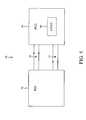
- FIG. 5is a block diagram of a Power over Ethernet (PoE) system according to an exemplary embodiment of the present invention.
- the power source equipment 102provides PoE and data communications over conductors 104 , 110 to a personal computing device (PCD) 502 having a representative electrical load 504 .
- the power source equipment 102provides PoE according to a known PoE standard, such as the IEEE 802.3afTM standard, an IEEE 802.3atTM standard, a legacy PoE transmission, and/or any suitable type of PoE transmission standard to provide some examples.
- a known PoE standardsuch as the IEEE 802.3afTM standard, an IEEE 802.3atTM standard, a legacy PoE transmission, and/or any suitable type of PoE transmission standard to provide some examples.
- the personal computing device 502 as described hereincan include a personal computer, a laptop, a handheld computing device, or any other powered device that is capable of receiving PoE and data communications over a communications link without departing from the spirit and scope of the invention.
- the personal computing device 502also includes data transceivers that operate according to a known communications standard, such as a 10 BASE-T, a 100 BASE-TX, a 1000 BASE-T, a 10 GBASE-T, and/or any other suitable communication standard to provide some examples.
- the power source equipment 102includes a physical layer device (PHY) on the power source equipment side that transmits and receives high speed data with a corresponding physical layer device in the personal computing device 502 , as will be discussed further below. Accordingly, the power transfer between the power source equipment 102 and the personal computing device 502 occurs simultaneously with the exchange of high speed data over the conductors 104 , 110 .
- PHYphysical layer device
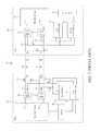
- FIG. 6Aillustrates a more detailed figure of the power transfer from a power source equipment (PSE) to a personal computing device (PCD) according to an exemplary embodiment of the present invention. More specifically, FIG. 6A provides a more detailed circuit diagram of the PoE system 500 , where the power source equipment 102 provides PoE and data communications to the personal computing device (PCD) 502 over conductor pairs 104 and 110 . In this exemplary embodiment, the power source equipment 102 provides power for PoE and for data communications over conductor pairs 104 and 110 in a substantially similar manner as previously described in FIG. 1 and FIG. 2 .
- the personal computing device 500includes a unified LOM 602 .
- the unified LOM 602combines the functionality of the PD controller 228 , as discussed in FIG. 2 , and the functionality of the LOM module 304 , as discussed in FIG. 3 , into a single unified subsystem.
- the unified LOM 602may be implemented using a single chip or die or multiple chips or dies.
- FIG. 6Billustrates a more detailed figure of a unified Local Area Network(LAN)-On-Motherboard (LOM) according to an exemplary embodiment of the present invention.
- the unified LOM 602includes a LOM 616 and a PD controller 618 .
- the LOM 616 and the PD controller 618are implemented on a single die or on a single chip.
- the unified LOM 602uses multiple dies or multiple chips to fabricating the LOM 616 and the PD controller 618 on multiple dies or within multiple chips.
- the PD controller 618may be implemented using a 100V process
- the LOM 616may be implemented using a 10V process.
- FIG. 6Cillustrates a more detailed figure of a unified Local Area Network(LAN)-On-Motherboard (LOM) according to another exemplary embodiment of the present invention.
- LOMLocal Area Network
- the LOM 616 and the PD controller 618are implemented on multiple dies or as multiple chips.
- an optional opto-isolator 620may be used to bypass the isolation boundary between the LOM 616 and the PD controller 618 .
- the unified LOM 602may be viewed as a single unified subsystem including the LOM module 616 and the PD controller 618 .
- the unified LOM 602seamlessly integrates PoE into a personal computing device by managing PoE through existing structure of the personal computing device, such as software drivers and Access Protocol Interfaces (API), to provide some examples.
- the LOM 602includes programmable registers and messages that may be read using existing software drivers and Access Protocol Interfaces of the personal computing device, thereby eliminating a need to develop new drivers and APIs.
- the PD controller 228monitors the voltage and current on the PD side of the PoE configuration and provides the necessary impedance signatures during initialization.
- the unified LOM 602monitors operational parameters, such as the voltage and the current of the personal computing device and provides the necessary impedance signatures during initialization, so that the PSE controller 218 will recognize the personal computing device as a valid PoE device, and be able to classify its power requirements. It is desirable to communicate these operational parameters to the power source equipment 102 using a communication via the data link layer, also referred to as layer two in the Open System Interconnection (OSI) networking model. Those skilled in the art(s) will recognize that these operational parameters may be communicated to the power source equipment 102 using any suitable means such as a physical layer, also referred to as a layer one, communication without departing from the spirit and scope of the invention.
- OSIOpen System Interconnection
- FIG. 7illustrates the Open System Interconnection (OSI) networking model, a part of which is incorporated into embodiments of the present invention.
- the OSI networking modelis a layered, abstract description for communications and computer network protocol design.
- the OSI networking modelis well known in the art.
- the PD 106communicates using a Physical Layer 702 .
- the Physical Layer 702also referred to as layer one, defines all the electrical and physical specifications for devices such as layout of pins, voltages, and cable specifications to provide some examples.
- the Physical Layer 702may establish and terminate a connection to a communications medium.
- the Physical Layer 702only provides one-way, one-time (static) communication and can be very slow.
- the unified LOM 602communicates via the Data Link Layer 704 .
- the Physical Layer 702conveys a bit stream (including electrical impulses, light, or radio signals, for example) through a network at the electrical and mechanical level, providing a hardware means of sending and receiving data on a carrier
- the Data Link Layer 704conveys data packets that include encoded bits and can provide transmission protocol knowledge and management including handling data errors.
- the Data Link Layer 704also referred to as layer two of the seven-layer OSI networking model, 704 provides the functional and procedural means to transfer data between network entities and to detect and correct errors that might occur in the Physical Layer 702 . Interfacing directly with the unified LOM 602 using the Data Link Layer 704 allows the operating system to capture parametric information, such as line voltage or line current to provide some examples, that otherwise is unavailable when using only the Physical Layer 702 .
- the Data Link Layer 704provides the interface for the unified LOM 602 to communicate parametric information.
- the Data Link Layer 704provides the personal computing devices 502 the ability to read the parametric information, such as line voltage or line current to provide some examples, at the physical port and to communicate the parametric information to the power source equipment 102 via a communication link. Communication via the Data Link Layer 704 allows a subsystem to manage PoE to be implemented within the unified LOM 602 to reduce latency, real-time demand and unnecessary host processor bandwidth needed to manage PoE functionality.
- a data communicationis passed between the unified LOM 602 and the ICH module 318 .
- the LOM module 616has full duplex transmit and receive capability through differential transmit port 614 and differential receive port 612 .
- a transformer 604couples high speed data between the first conductor pair 104 and the receive port 612 .
- a second transformer 606couples high speed data between the transmit port 614 and the second conductor pair 110 .
- the respective transformers 604 and 606pass the high speed data to and from the unified LOM 602 , but isolate any low frequency or DC voltage from the sensitive transceiver data ports.
- the transformer 604includes primary and secondary windings, where the secondary winding (on the conductor side) includes a center tap 608 .
- the second transformer 606includes primary and secondary windings, where the secondary winding (on the conductor side) includes a center tap 610 .
- the center taps 608 and 610supply the power for PoE carried over conductors 104 and 110 to the representative load 504 of the personal computing devices 502 , where the load 504 represents the dynamic power draw needed to operate personal computing devices 502 .
- a DC-DC converter 230may be optionally inserted before the load 504 to step down the voltage as necessary to meet the voltage requirements of the personal computing devices 502 . Further, multiple DC-DC converters 230 may be arrayed in parallel to output multiple different voltages (3 volts, 5 volts, 12 volts) to supply different loads 404 of the personal computing devices 502 .
- a direct current (I DC ) 238flows from the DC power supply 216 through the first center tap 210 , and divides into a first current (I 1 ) 240 and a second current (I 2 ) 242 that is carried over conductor pair 104 .
- the first current (I 1 ) 240 and the second current (I 2 ) 242then recombine at the center tap 608 to reform the direct current (I DC ) 238 so as to power the personal computing devices 502 .
- the direct current (I DC ) 238flows from the personal computing devices 502 through the second center tap 610 , and divides for transport over conductor pair 110 .
- the return DC currentrecombines at the second center tap 214 , and returns to the DC power supply 216 .
- data transmission between the power source equipment 102 and the personal computing devices 502occurs simultaneously with the DC power supply described above. Accordingly, a first communication signal 244 and/or a second communication signal 246 are simultaneously differentially carried via the conductor pairs 104 and 110 between the power source equipment 102 and the personal computing devices 502 . It is important to note that the communication signals 244 and 246 are differential signals that ideally are not effected by the DC power transfer.
- FIG. 8illustrates a more detailed figure of the power transfer from a power source equipment (PSE) to a laptop computing device (LCD) according to an exemplary embodiment of the present invention. More specifically, FIG. 8 provides a more detailed circuit diagram of the PoE system 500 , where the power source equipment 102 provides PoE and data communications to a laptop computing device (LCD) 802 over conductor pairs 104 and 110 . In this exemplary embodiment, the power source equipment 102 provides PoE and data over conductor pairs 104 and 110 in a substantially similar manner as previously described in FIG. 1 and FIG. 2 .
- the laptop computing device 802includes a unified LOM 602 .
- the operation and implementation of the unified LOM 602is previously described above in FIG. 6A through FIG. 7 .
- the LCD 802also includes a PoE power module 804 .
- the PoE power module 804can include, for example, power regulator 806 , a power source selector 808 , and a battery charger 810 .
- a power regulator 806may be optionally inserted before the load 504 to step down the voltage as necessary to meet the voltage requirements of the LCD 802 . Further, multiple power regulators 806 may be arrayed in parallel to output multiple different voltages (3 volts, 5 volts, 12 volts) to supply different loads 504 to the LCD 802 .
- Powersuch as the direct current (I DC ) 238 , can be delivered to the battery charger 810 within the PoE power module 804 , in order to charge a battery, for example.
- FIG. 9illustrates a Power over Ethernet (PoE) configuration in a computing environment, according to an exemplary embodiment of the present invention.
- a computing environment 900includes personal computing devices 902 . 1 through 902 .n, hereinafter referred to as the personal computing devices 902 and the powered devices 402 .
- Computing environment 900can be a conference room, for example, or any other environment in which the personal computing devices 902 are networked.
- the personal computing devices 902include any suitable device, such as a the personal computing device (PCD) 702 , the laptop computing device (LCD) 802 , or any other suitable device that receives power for PoE and for data communications over a communications link.
- PCDpersonal computing device
- LCDlaptop computing device
- a power supply 906provides prove for PoE and for data communications to the personal computing devices 902 and to the powered devices 402 via a network switch 904 .
- the network switch 904may be any networking switch that is capable of providing PoE and data communications to the personal computing devices and/or the powered devices.
- the network switch 904includes one or more data ports to provide PoE and data communications to the personal computing devices and/or the powered devices.
- the network switch 904may have as little as two data ports or as many as 400 or more data ports.
- the network switchprovides power for PoE and for data communications to the personal computing devices 902 through a corresponding interface 950 . 1 through 950 .n, hereinafter referred to as the interface 950 .
- the interface 950may include any communication link that can handle PoE, such as various types of Ethernet cabling, for example.
- the network switch 904provides PoE and data communications to the powered devices 402 through the interface 452 .
Landscapes
- Engineering & Computer Science (AREA)
- General Engineering & Computer Science (AREA)
- Theoretical Computer Science (AREA)
- Computer Hardware Design (AREA)
- Physics & Mathematics (AREA)
- General Physics & Mathematics (AREA)
- Computer Networks & Wireless Communication (AREA)
- Signal Processing (AREA)
- Small-Scale Networks (AREA)
Abstract
Description
Claims (28)
Priority Applications (3)
| Application Number | Priority Date | Filing Date | Title |
|---|---|---|---|
| US11/797,616US7921310B2 (en) | 2006-06-28 | 2007-05-04 | Unified powered device (PD) controller and LAN on motherboard (LOM) in a personal computing device (PCD) |
| EP20080007930EP1988659B1 (en) | 2007-05-04 | 2008-04-24 | Unified powered device (PD) and LAN on motherboard (LOM) controller for a personal computing device (PC) in a Power over Ethernet system. |
| DE200860002632DE602008002632D1 (en) | 2007-05-04 | 2008-04-24 | Unified Powered Device (PD) and LAN-on-Motherboard (LOM) control for a personal computing device (PC) in a Power-over-Ethernet system. |
Applications Claiming Priority (2)
| Application Number | Priority Date | Filing Date | Title |
|---|---|---|---|
| US81687906P | 2006-06-28 | 2006-06-28 | |
| US11/797,616US7921310B2 (en) | 2006-06-28 | 2007-05-04 | Unified powered device (PD) controller and LAN on motherboard (LOM) in a personal computing device (PCD) |
Publications (2)
| Publication Number | Publication Date |
|---|---|
| US20080005433A1 US20080005433A1 (en) | 2008-01-03 |
| US7921310B2true US7921310B2 (en) | 2011-04-05 |
Family
ID=38878195
Family Applications (1)
| Application Number | Title | Priority Date | Filing Date |
|---|---|---|---|
| US11/797,616Expired - Fee RelatedUS7921310B2 (en) | 2006-06-28 | 2007-05-04 | Unified powered device (PD) controller and LAN on motherboard (LOM) in a personal computing device (PCD) |
Country Status (1)
| Country | Link |
|---|---|
| US (1) | US7921310B2 (en) |
Cited By (2)
| Publication number | Priority date | Publication date | Assignee | Title |
|---|---|---|---|---|
| US20090152943A1 (en)* | 2007-12-17 | 2009-06-18 | Wael William Diab | Method and system for vehicular power distribution utilizing power over ethernet |
| US20130275784A1 (en)* | 2010-10-27 | 2013-10-17 | Volkswagen Ag | Network and method for operating a network |
Families Citing this family (24)
| Publication number | Priority date | Publication date | Assignee | Title |
|---|---|---|---|---|
| US7873844B2 (en)* | 2006-06-28 | 2011-01-18 | Broadcom Corporation | Physical separation and recognition mechanism for a switch and a power supply for power over Ethernet (PoE) in enterprise environments |
| US7890776B2 (en)* | 2006-06-28 | 2011-02-15 | Broadcom Corporation | Use of priority information to intelligently allocate power for personal computing devices in a Power-over-Ethernet system |
| US7774634B2 (en) | 2006-06-28 | 2010-08-10 | Broadcom Corporation | Layer 2 power classification support for Power-over-Ethernet personal computing devices |
| US7752472B2 (en)* | 2006-06-28 | 2010-07-06 | Broadcom Corporation | Protocol and interface between a LAN on motherboard (LOM) and a powered device (PD) for a personal computing device (PCD) |
| US7966504B2 (en)* | 2007-04-11 | 2011-06-21 | Broadcom Corporation | System and method for power management in a computing device for power over ethernet |
| US7890777B2 (en)* | 2007-04-11 | 2011-02-15 | Broadcom Corporation | System and method for collecting power management parameters in a computing device for power over Ethernet |
| US8392964B2 (en)* | 2007-04-11 | 2013-03-05 | Broadcom Corporation | System and method for authenticating a powered device attached to a power sourcing equipment for power provisioning |
| US7870401B2 (en)* | 2007-08-15 | 2011-01-11 | Broadcom Corporation | System and method for power over Ethernet provisioning for a computing device using a network user profile |
| US8001399B2 (en)* | 2007-09-12 | 2011-08-16 | Broadcom Corporation | System and method for secure communication for power over ethernet between a computing device and a switch |
| US7908495B2 (en)* | 2007-10-11 | 2011-03-15 | Broadcom Corporation | System and method for implementing fairness in the powering of computing devices in a power over ethernet application |
| US7966502B2 (en) | 2007-12-20 | 2011-06-21 | Broadcom Corporation | System and method for enabling power over ethernet for legacy devices |
| US9030976B2 (en)* | 2008-03-27 | 2015-05-12 | Silicon Image, Inc. | Bi-directional digital interface for video and audio (DIVA) |
| JP2012512567A (en)* | 2008-12-11 | 2012-05-31 | シナーチップ カンパニー リミテッド | Power supply to bi-directional digital interface for video and audio |
| US20100186234A1 (en) | 2009-01-28 | 2010-07-29 | Yehuda Binder | Electric shaver with imaging capability |
| US20130191570A1 (en) | 2010-01-12 | 2013-07-25 | Synerchip Co., Ltd. | MULTI-MEDIA USB DATA TRANSFER OVER DIGITAL INTERACTION INTERFACE FOR VIDEO AND AUDIO (DiiVA) |
| US8788865B2 (en) | 2011-05-17 | 2014-07-22 | Hewlett-Packard Development Company, L.P. | Method and system for redeploying powered devices from a power sourcing equipment with insufficient power capacity to another power sourcing equipment with excess power capacity |
| CN103365259B (en)* | 2012-04-10 | 2016-09-28 | 泰科电子(上海)有限公司 | Control circuit module, electrical equipment and modulation-demodulation device |
| US10050668B1 (en)* | 2012-04-20 | 2018-08-14 | Securus Technologies, Inc. | Integrated network devices utilizing low-power technologies |
| US9135204B1 (en)* | 2012-05-14 | 2015-09-15 | Rockwell Collins, Inc. | Hardened DVI interface |
| US9859951B2 (en)* | 2013-11-26 | 2018-01-02 | Linear Technology Corporation | Power over data lines detection and classification scheme |
| US10416715B1 (en)* | 2018-03-06 | 2019-09-17 | Securus Technologies, Inc. | Personal computer wireless device docking station on low power network |
| US11561580B1 (en) | 2018-03-06 | 2023-01-24 | Securus Technologies, Llc | Controlled-environment facility communication terminal and personal computer wireless device docking station with integral keypads |
| US11619971B1 (en) | 2018-03-06 | 2023-04-04 | Securus Technologies, Inc. | Personal computer wireless device docking station |
| CN118473841B (en)* | 2024-07-11 | 2024-10-22 | 库卡机器人(广东)有限公司 | Power over Ethernet system, power supply method, device and readable storage medium |
Citations (36)
| Publication number | Priority date | Publication date | Assignee | Title |
|---|---|---|---|---|
| US5889381A (en) | 1997-03-14 | 1999-03-30 | Ericsson, Inc. | Means of communication between a battery pack and a battery powered device |
| US6473608B1 (en) | 1999-01-12 | 2002-10-29 | Powerdsine Ltd. | Structure cabling system |
| US6764343B2 (en) | 2002-04-10 | 2004-07-20 | Power Dsine, Ltd. | Active local area network connector |
| WO2005036815A1 (en) | 2003-10-16 | 2005-04-21 | Powerdsine Ltd. | High power architecture for power over ethernet |
| US20050097378A1 (en)* | 2003-07-29 | 2005-05-05 | Hwang Andrew S. | Method and system for power management in a gigabit Ethernet chip |
| US6909943B2 (en) | 1999-01-12 | 2005-06-21 | Power Dsine, Ltd. | System for power delivery over data communication cabling infrastructure |
| US20050136989A1 (en)* | 2003-12-12 | 2005-06-23 | Dove Daniel J. | Method and system for distributing power to networked devices |
| US20050276023A1 (en) | 2002-12-16 | 2005-12-15 | Network Appliance, Inc. | Universal modular power supply carrier |
| US6986071B2 (en) | 2002-02-01 | 2006-01-10 | Powerdsine, Ltd. | Detecting network power connection status using AC signals |
| US7046983B2 (en) | 1999-08-02 | 2006-05-16 | Powerdsine, Ltd. | Integral board and module for power over LAN |
| US20060215680A1 (en)* | 2005-03-28 | 2006-09-28 | Camagna John R | Method for high voltage power feed on differential cable pairs |
| US7117272B2 (en) | 2004-04-19 | 2006-10-03 | Powerdsine Ltd. | Interchangeable power over Ethernet module |
| US20060242458A1 (en)* | 2005-03-31 | 2006-10-26 | Daniel Feldman | Computer volatile memory power backup system |
| US20060244462A1 (en) | 2005-04-27 | 2006-11-02 | Mccosh John C | System and method for characterizing power on a local area network |
| US20060251179A1 (en)* | 2005-03-28 | 2006-11-09 | Akros Silicon, Inc. | Ethernet bridge |
| US7143299B1 (en) | 2001-03-20 | 2006-11-28 | 3Com Corporation | Method for power management of intelligent hardware |
| US20070041577A1 (en)* | 2005-03-28 | 2007-02-22 | Akros Silicon, Inc. | Ethernet module |
| US20070074052A1 (en) | 2005-09-26 | 2007-03-29 | Texas Instruments Incorporated | System architecture for a power distribution network and method of operation |
| US20070079151A1 (en)* | 2005-09-30 | 2007-04-05 | Patrick Connor | System powered from a local area network cable |
| US20070110360A1 (en) | 2005-11-15 | 2007-05-17 | Linear Technology Corporation | Dynamic power allocation in system for providing power over communication link |
| US7231535B2 (en) | 2003-10-10 | 2007-06-12 | Alcatel | Ethernet card for connection to a local network, for controlling connection to a communication terminal |
| US20070220280A1 (en)* | 2006-03-14 | 2007-09-20 | Cisco Technology, Inc. | Method and apparatus for changing power class for a powered device |
| US20070257780A1 (en) | 2006-05-08 | 2007-11-08 | Cisco Technology, Inc. | Inline power allocation for power over Ethernet applications |
| US20080005600A1 (en) | 2006-06-28 | 2008-01-03 | Broadcom Corporation | Intelligent power over Ethernet power management for personal computing devices in enterprise environments |
| US20080005601A1 (en) | 2006-06-28 | 2008-01-03 | Broadcom Corporation | Layer 2 power classification support for power-over-Ethernet personal computing devices |
| US20080005602A1 (en) | 2006-06-28 | 2008-01-03 | Broadcom Corporation | Physical separation and recognition mechanism for a switch and a power supply for power over Ethernet (POE) in enterprise environments |
| US7320078B2 (en) | 2005-06-03 | 2008-01-15 | Cisco Technology, Inc. | Controlling delivery of power and network communications to a set of devices |
| US20080016263A1 (en) | 2006-06-28 | 2008-01-17 | Broadcom Corporation | Protocol and interface between a LAN on motherboard (LOM) and a powered device (PD) for a personal computing device (PCD) |
| US7337336B2 (en) | 2004-05-10 | 2008-02-26 | Microsemi Corp.-Analog Mixed Signal Group Ltd. | Method for rapid port power reduction |
| US20080052546A1 (en) | 2006-08-25 | 2008-02-28 | Cisco Technology, Inc. | Inline power policing |
| US7340325B2 (en) | 2005-08-03 | 2008-03-04 | Texas Instruments Incorporated | Priority powerdown system and method for power distribution systems |
| US7343506B1 (en) | 2005-02-17 | 2008-03-11 | Apple, Inc. | Automatic power management of a network powered device |
| US7363525B2 (en) | 2004-10-07 | 2008-04-22 | Cisco Technology, Inc. | Bidirectional inline power port |
| US7368798B2 (en) | 2005-03-28 | 2008-05-06 | Akros Silicon Inc. | Integrated DC/DC converter substrate connections |
| US7549067B2 (en) | 2004-12-21 | 2009-06-16 | Alcatel Lucent | Power prioritization in power source equipment |
| US20090265563A1 (en)* | 2005-03-28 | 2009-10-22 | Camagna John R | Systems and methods operable to allow loop powering of networked devices |
- 2007
- 2007-05-04USUS11/797,616patent/US7921310B2/ennot_activeExpired - Fee Related
Patent Citations (38)
| Publication number | Priority date | Publication date | Assignee | Title |
|---|---|---|---|---|
| US5889381A (en) | 1997-03-14 | 1999-03-30 | Ericsson, Inc. | Means of communication between a battery pack and a battery powered device |
| US6473608B1 (en) | 1999-01-12 | 2002-10-29 | Powerdsine Ltd. | Structure cabling system |
| US6909943B2 (en) | 1999-01-12 | 2005-06-21 | Power Dsine, Ltd. | System for power delivery over data communication cabling infrastructure |
| US7046983B2 (en) | 1999-08-02 | 2006-05-16 | Powerdsine, Ltd. | Integral board and module for power over LAN |
| US7143299B1 (en) | 2001-03-20 | 2006-11-28 | 3Com Corporation | Method for power management of intelligent hardware |
| US6986071B2 (en) | 2002-02-01 | 2006-01-10 | Powerdsine, Ltd. | Detecting network power connection status using AC signals |
| US6764343B2 (en) | 2002-04-10 | 2004-07-20 | Power Dsine, Ltd. | Active local area network connector |
| US20050276023A1 (en) | 2002-12-16 | 2005-12-15 | Network Appliance, Inc. | Universal modular power supply carrier |
| US20050097378A1 (en)* | 2003-07-29 | 2005-05-05 | Hwang Andrew S. | Method and system for power management in a gigabit Ethernet chip |
| US7231535B2 (en) | 2003-10-10 | 2007-06-12 | Alcatel | Ethernet card for connection to a local network, for controlling connection to a communication terminal |
| WO2005036815A1 (en) | 2003-10-16 | 2005-04-21 | Powerdsine Ltd. | High power architecture for power over ethernet |
| US20050136989A1 (en)* | 2003-12-12 | 2005-06-23 | Dove Daniel J. | Method and system for distributing power to networked devices |
| US7203849B2 (en) | 2003-12-12 | 2007-04-10 | Hewlett-Packard Development Company, L.P. | Method and system for distributing power to networked devices |
| US7117272B2 (en) | 2004-04-19 | 2006-10-03 | Powerdsine Ltd. | Interchangeable power over Ethernet module |
| US7337336B2 (en) | 2004-05-10 | 2008-02-26 | Microsemi Corp.-Analog Mixed Signal Group Ltd. | Method for rapid port power reduction |
| US7363525B2 (en) | 2004-10-07 | 2008-04-22 | Cisco Technology, Inc. | Bidirectional inline power port |
| US7549067B2 (en) | 2004-12-21 | 2009-06-16 | Alcatel Lucent | Power prioritization in power source equipment |
| US7343506B1 (en) | 2005-02-17 | 2008-03-11 | Apple, Inc. | Automatic power management of a network powered device |
| US20090265563A1 (en)* | 2005-03-28 | 2009-10-22 | Camagna John R | Systems and methods operable to allow loop powering of networked devices |
| US20070041577A1 (en)* | 2005-03-28 | 2007-02-22 | Akros Silicon, Inc. | Ethernet module |
| US20060251179A1 (en)* | 2005-03-28 | 2006-11-09 | Akros Silicon, Inc. | Ethernet bridge |
| US7368798B2 (en) | 2005-03-28 | 2008-05-06 | Akros Silicon Inc. | Integrated DC/DC converter substrate connections |
| US20060215680A1 (en)* | 2005-03-28 | 2006-09-28 | Camagna John R | Method for high voltage power feed on differential cable pairs |
| US20060242458A1 (en)* | 2005-03-31 | 2006-10-26 | Daniel Feldman | Computer volatile memory power backup system |
| US20060244462A1 (en) | 2005-04-27 | 2006-11-02 | Mccosh John C | System and method for characterizing power on a local area network |
| US7320078B2 (en) | 2005-06-03 | 2008-01-15 | Cisco Technology, Inc. | Controlling delivery of power and network communications to a set of devices |
| US7340325B2 (en) | 2005-08-03 | 2008-03-04 | Texas Instruments Incorporated | Priority powerdown system and method for power distribution systems |
| US20070074052A1 (en) | 2005-09-26 | 2007-03-29 | Texas Instruments Incorporated | System architecture for a power distribution network and method of operation |
| US7454641B2 (en) | 2005-09-30 | 2008-11-18 | Intel Corporation | System powered from a local area network cable |
| US20070079151A1 (en)* | 2005-09-30 | 2007-04-05 | Patrick Connor | System powered from a local area network cable |
| US20070110360A1 (en) | 2005-11-15 | 2007-05-17 | Linear Technology Corporation | Dynamic power allocation in system for providing power over communication link |
| US20070220280A1 (en)* | 2006-03-14 | 2007-09-20 | Cisco Technology, Inc. | Method and apparatus for changing power class for a powered device |
| US20070257780A1 (en) | 2006-05-08 | 2007-11-08 | Cisco Technology, Inc. | Inline power allocation for power over Ethernet applications |
| US20080005602A1 (en) | 2006-06-28 | 2008-01-03 | Broadcom Corporation | Physical separation and recognition mechanism for a switch and a power supply for power over Ethernet (POE) in enterprise environments |
| US20080005601A1 (en) | 2006-06-28 | 2008-01-03 | Broadcom Corporation | Layer 2 power classification support for power-over-Ethernet personal computing devices |
| US20080016263A1 (en) | 2006-06-28 | 2008-01-17 | Broadcom Corporation | Protocol and interface between a LAN on motherboard (LOM) and a powered device (PD) for a personal computing device (PCD) |
| US20080005600A1 (en) | 2006-06-28 | 2008-01-03 | Broadcom Corporation | Intelligent power over Ethernet power management for personal computing devices in enterprise environments |
| US20080052546A1 (en) | 2006-08-25 | 2008-02-28 | Cisco Technology, Inc. | Inline power policing |
Non-Patent Citations (2)
| Title |
|---|
| 802.3af(TM), IEEE Standard for Information Technology-Telecommunications and information exchange between systems-Local and metropolitan area networks-Specific requirements, Part 3: Carrier Sense Multiple Access with Collision Detection (CSMA/CD) Access Method and Physical Layer Specifications, Amendment: Data Terminal Equipment (DTE) Power via Media Dependent Interface (MDI), IEEE Computer Society, IEEE, New York, NY, ISBN 0-7381-3696-4 (SH95132) (Print), ISBN 0-7381-3697-2 (SS95132) (PDF), Jun. 18, 2003, pp. i-ix and 1-121 (133 pages total). |
| 802.3af™, IEEE Standard for Information Technology—Telecommunications and information exchange between systems—Local and metropolitan area networks—Specific requirements, Part 3: Carrier Sense Multiple Access with Collision Detection (CSMA/CD) Access Method and Physical Layer Specifications, Amendment: Data Terminal Equipment (DTE) Power via Media Dependent Interface (MDI), IEEE Computer Society, IEEE, New York, NY, ISBN 0-7381-3696-4 (SH95132) (Print), ISBN 0-7381-3697-2 (SS95132) (PDF), Jun. 18, 2003, pp. i-ix and 1-121 (133 pages total). |
Cited By (3)
| Publication number | Priority date | Publication date | Assignee | Title |
|---|---|---|---|---|
| US20090152943A1 (en)* | 2007-12-17 | 2009-06-18 | Wael William Diab | Method and system for vehicular power distribution utilizing power over ethernet |
| US20130275784A1 (en)* | 2010-10-27 | 2013-10-17 | Volkswagen Ag | Network and method for operating a network |
| US9442543B2 (en)* | 2010-10-27 | 2016-09-13 | Volkswagen Ag | Network and method for operating a network |
Also Published As
| Publication number | Publication date |
|---|---|
| US20080005433A1 (en) | 2008-01-03 |
Similar Documents
| Publication | Publication Date | Title |
|---|---|---|
| US7921310B2 (en) | Unified powered device (PD) controller and LAN on motherboard (LOM) in a personal computing device (PCD) | |
| US7752472B2 (en) | Protocol and interface between a LAN on motherboard (LOM) and a powered device (PD) for a personal computing device (PCD) | |
| EP1838032B1 (en) | Inband management for power over ethernet midspans using an embedded switch | |
| US7774634B2 (en) | Layer 2 power classification support for Power-over-Ethernet personal computing devices | |
| US8301918B2 (en) | Intelligent power over ethernet power management for personal computing devices in enterprise environments | |
| US7873844B2 (en) | Physical separation and recognition mechanism for a switch and a power supply for power over Ethernet (PoE) in enterprise environments | |
| US8341440B2 (en) | Power sharing between midspan and endspan for higher power PoE | |
| US9379988B2 (en) | Multi-rate MAC to PHY interface | |
| US20090164805A1 (en) | System and method for enabling power over ethernet for legacy devices | |
| US20140129853A1 (en) | Advertising power over ethernet (POE) capabilities among nodes in a POE system using type-length-value (TLV) structures | |
| EP1981208B1 (en) | Poe communication bus, interface, and protocol between poe subsystem and phy or switch subsystems | |
| US8533502B2 (en) | System and method for physical layer device enabled power over Ethernet processing | |
| US8909953B2 (en) | Unified bus architecture for PoE communication and control | |
| US20140129854A1 (en) | Auto-Negotiation and Advanced Classification for Power Over Ethernet (POE) Systems | |
| EP1988659B1 (en) | Unified powered device (PD) and LAN on motherboard (LOM) controller for a personal computing device (PC) in a Power over Ethernet system. | |
| US8806064B2 (en) | Virtual interface to the PoE device through an expanded registered map in a networking device such as a PHY | |
| CN116483765A (en) | Device and method for multi-channel USB shared network |
Legal Events
| Date | Code | Title | Description |
|---|---|---|---|
| AS | Assignment | Owner name:BROADCOM CORPORATION, CALIFORNIA Free format text:ASSIGNMENT OF ASSIGNORS INTEREST;ASSIGNORS:DIAB, WAEL WILLIAM;ASSOUAD, SIMON;REEL/FRAME:019343/0073;SIGNING DATES FROM 20070425 TO 20070430 Owner name:BROADCOM CORPORATION, CALIFORNIA Free format text:ASSIGNMENT OF ASSIGNORS INTEREST;ASSIGNORS:DIAB, WAEL WILLIAM;ASSOUAD, SIMON;SIGNING DATES FROM 20070425 TO 20070430;REEL/FRAME:019343/0073 | |
| STCF | Information on status: patent grant | Free format text:PATENTED CASE | |
| FPAY | Fee payment | Year of fee payment:4 | |
| SULP | Surcharge for late payment | ||
| AS | Assignment | Owner name:BANK OF AMERICA, N.A., AS COLLATERAL AGENT, NORTH CAROLINA Free format text:PATENT SECURITY AGREEMENT;ASSIGNOR:BROADCOM CORPORATION;REEL/FRAME:037806/0001 Effective date:20160201 Owner name:BANK OF AMERICA, N.A., AS COLLATERAL AGENT, NORTH Free format text:PATENT SECURITY AGREEMENT;ASSIGNOR:BROADCOM CORPORATION;REEL/FRAME:037806/0001 Effective date:20160201 | |
| AS | Assignment | Owner name:AVAGO TECHNOLOGIES GENERAL IP (SINGAPORE) PTE. LTD., SINGAPORE Free format text:ASSIGNMENT OF ASSIGNORS INTEREST;ASSIGNOR:BROADCOM CORPORATION;REEL/FRAME:041706/0001 Effective date:20170120 Owner name:AVAGO TECHNOLOGIES GENERAL IP (SINGAPORE) PTE. LTD Free format text:ASSIGNMENT OF ASSIGNORS INTEREST;ASSIGNOR:BROADCOM CORPORATION;REEL/FRAME:041706/0001 Effective date:20170120 | |
| AS | Assignment | Owner name:BROADCOM CORPORATION, CALIFORNIA Free format text:TERMINATION AND RELEASE OF SECURITY INTEREST IN PATENTS;ASSIGNOR:BANK OF AMERICA, N.A., AS COLLATERAL AGENT;REEL/FRAME:041712/0001 Effective date:20170119 | |
| AS | Assignment | Owner name:AVAGO TECHNOLOGIES INTERNATIONAL SALES PTE. LIMITE Free format text:MERGER;ASSIGNOR:AVAGO TECHNOLOGIES GENERAL IP (SINGAPORE) PTE. LTD.;REEL/FRAME:047196/0687 Effective date:20180509 | |
| MAFP | Maintenance fee payment | Free format text:PAYMENT OF MAINTENANCE FEE, 8TH YEAR, LARGE ENTITY (ORIGINAL EVENT CODE: M1552); ENTITY STATUS OF PATENT OWNER: LARGE ENTITY Year of fee payment:8 | |
| AS | Assignment | Owner name:AVAGO TECHNOLOGIES INTERNATIONAL SALES PTE. LIMITE Free format text:CORRECTIVE ASSIGNMENT TO CORRECT THE EFFECTIVE DATE OF MERGER TO 9/5/2018 PREVIOUSLY RECORDED AT REEL: 047196 FRAME: 0687. ASSIGNOR(S) HEREBY CONFIRMS THE MERGER;ASSIGNOR:AVAGO TECHNOLOGIES GENERAL IP (SINGAPORE) PTE. LTD.;REEL/FRAME:047630/0344 Effective date:20180905 | |
| AS | Assignment | Owner name:AVAGO TECHNOLOGIES INTERNATIONAL SALES PTE. LIMITE Free format text:CORRECTIVE ASSIGNMENT TO CORRECT THE PROPERTY NUMBERS PREVIOUSLY RECORDED AT REEL: 47630 FRAME: 344. ASSIGNOR(S) HEREBY CONFIRMS THE ASSIGNMENT;ASSIGNOR:AVAGO TECHNOLOGIES GENERAL IP (SINGAPORE) PTE. LTD.;REEL/FRAME:048883/0267 Effective date:20180905 | |
| FEPP | Fee payment procedure | Free format text:MAINTENANCE FEE REMINDER MAILED (ORIGINAL EVENT CODE: REM.); ENTITY STATUS OF PATENT OWNER: LARGE ENTITY | |
| LAPS | Lapse for failure to pay maintenance fees | Free format text:PATENT EXPIRED FOR FAILURE TO PAY MAINTENANCE FEES (ORIGINAL EVENT CODE: EXP.); ENTITY STATUS OF PATENT OWNER: LARGE ENTITY | |
| STCH | Information on status: patent discontinuation | Free format text:PATENT EXPIRED DUE TO NONPAYMENT OF MAINTENANCE FEES UNDER 37 CFR 1.362 | |
| FP | Lapsed due to failure to pay maintenance fee | Effective date:20230405 |