US7920969B2 - System for and method of determining a host vehicle lane change - Google Patents
System for and method of determining a host vehicle lane changeDownload PDFInfo
- Publication number
- US7920969B2 US7920969B2US11/436,497US43649706AUS7920969B2US 7920969 B2US7920969 B2US 7920969B2US 43649706 AUS43649706 AUS 43649706AUS 7920969 B2US7920969 B2US 7920969B2
- Authority
- US
- United States
- Prior art keywords
- vehicle
- host vehicle
- remote
- coordinates
- host
- Prior art date
- Legal status (The legal status is an assumption and is not a legal conclusion. Google has not performed a legal analysis and makes no representation as to the accuracy of the status listed.)
- Expired - Fee Related, expires
Links
- 238000000034methodMethods0.000titleclaimsdescription19
- 230000008859changeEffects0.000titleclaimsdescription15
- 238000004891communicationMethods0.000claimsabstractdescription13
- 230000004913activationEffects0.000claimsdescription5
- 230000001186cumulative effectEffects0.000claimsdescription5
- 230000005540biological transmissionEffects0.000abstractdescription2
- 230000001953sensory effectEffects0.000description6
- 238000005516engineering processMethods0.000description4
- 238000004458analytical methodMethods0.000description2
- 238000001514detection methodMethods0.000description2
- 238000010586diagramMethods0.000description2
- 230000006870functionEffects0.000description2
- 230000033001locomotionEffects0.000description2
- 238000005259measurementMethods0.000description2
- 238000005070samplingMethods0.000description2
- 238000013459approachMethods0.000description1
- 238000013479data entryMethods0.000description1
- 238000013461designMethods0.000description1
- 238000013213extrapolationMethods0.000description1
- 238000004519manufacturing processMethods0.000description1
- 238000012986modificationMethods0.000description1
- 230000004048modificationEffects0.000description1
- 238000012544monitoring processMethods0.000description1
- 230000004899motilityEffects0.000description1
- 230000008569processEffects0.000description1
- 238000012545processingMethods0.000description1
- 230000008439repair processEffects0.000description1
- 238000012549trainingMethods0.000description1
- 230000016776visual perceptionEffects0.000description1
Images


Classifications
- B—PERFORMING OPERATIONS; TRANSPORTING
- B60—VEHICLES IN GENERAL
- B60T—VEHICLE BRAKE CONTROL SYSTEMS OR PARTS THEREOF; BRAKE CONTROL SYSTEMS OR PARTS THEREOF, IN GENERAL; ARRANGEMENT OF BRAKING ELEMENTS ON VEHICLES IN GENERAL; PORTABLE DEVICES FOR PREVENTING UNWANTED MOVEMENT OF VEHICLES; VEHICLE MODIFICATIONS TO FACILITATE COOLING OF BRAKES
- B60T7/00—Brake-action initiating means
- B60T7/12—Brake-action initiating means for automatic initiation; for initiation not subject to will of driver or passenger
- B60T7/22—Brake-action initiating means for automatic initiation; for initiation not subject to will of driver or passenger initiated by contact of vehicle, e.g. bumper, with an external object, e.g. another vehicle, or by means of contactless obstacle detectors mounted on the vehicle
- G—PHYSICS
- G08—SIGNALLING
- G08G—TRAFFIC CONTROL SYSTEMS
- G08G1/00—Traffic control systems for road vehicles
- G08G1/16—Anti-collision systems
- G08G1/161—Decentralised systems, e.g. inter-vehicle communication
- G08G1/163—Decentralised systems, e.g. inter-vehicle communication involving continuous checking
Definitions
- the present inventionrelates to active safety applications and real-time vehicle tracking systems, and more particularly to an improved system for determining a host vehicle congruent path divergence relative to at least one traveling remote vehicle.
- V2V communication systemshave been developed for relaying in-vehicle data to other V2V equipped vehicles within the operating range of the communication system.
- V2V systemstypically employ one of several conventional short-range communication technologies such as Radio Frequency (RF), or a short-range local radio network, to deliver their messages.
- RFRadio Frequency
- V2V communication systemshave not been adapted for use by preventative tracking solutions. Instead, V2V functionality is frustrated, in this regard, where a misguided arrear vehicle veers from the desirous path and falls out of sensory tracking range.
- a system and method of determining a congruent path divergence, such as a lane change, by an arrear vehicleis described.
- the inventive systempreferably relies upon pluralities of position coordinates, yaw rates, and headings for a host vehicle and at least one remote vehicle, to determine relative yaw, lateral distance, and heading discrepancies for the host vehicle.
- the inventive systemutilizes trigonometric relationships and extrapolation between successive points within a measurement period, wherein the position coordinates, yaw rate, and heading of the vehicles are determined at each point.
- a first aspect of the present inventionconcerns a tracking system adapted for use with a traveling host vehicle spaced from and communicatively coupled to at least one traveling remote vehicle that precedes the host vehicle.
- the systemincludes a remote vehicle locator device configured to determine and cause to be stored for at least a period sets of current position, and trail coordinates for said at least one remote vehicle.
- a remote vehicle sensoris configured to determine and cause to be stored for at least a period a data value of a condition relating to the remote vehicle, at each of said stored remote vehicle positions.
- a host vehicle locator deviceis included and configured to determine and cause to be stored for at least a period sets of current position and trail coordinates for said host vehicle, while a host vehicle sensor is likewise configured to determine and cause to be stored for at least a period data values of the condition relating to the host vehicle, at the current host vehicle position.
- an inventive host vehicle controlleris communicatively coupled to the devices and sensors, and configured to compare the current position and trail coordinates of the host and remote vehicles, so as to determine the relative positioning of the vehicles.
- the controlleris further configured to compare the host vehicle current position data value to the stored remote vehicle data values at the two most proximate remote vehicle trail coordinates, relative to the current host vehicle position, when the remote vehicle precedes the host vehicle, so as to autonomously determine a data discrepancy.
- the controlleris further configured to compare the discrepancy to a threshold, so as to determine a congruent path divergence by the host vehicle, wherein said data, discrepancy, and threshold are cooperatively configured to indicate the congruent path divergence by the host vehicle.
- a second aspect of the present inventionconcerns a method of detecting the path divergence of a traveling host vehicle by a communicatively coupled congruently traveling remote vehicle.
- the methodcomprises the steps of determining and storing a plurality of sets of current position and trail coordinates, and yaw rates at each set of coordinates, for the traveling remote and host vehicles.
- the sets of coordinatesare compared to determine lateral deviation of the host vehicle relative to the remote vehicle trail coordinates so as to determine the relative positioning discrepancies of the vehicles, and the relative headings of the vehicles at each set of coordinates are determined.
- the yaw rates and headings of the host vehicle at its current position coordinates, and the two most proximate remote vehicle trail coordinates relative to the current host vehicle positionare compared, so as to determine yaw rate and heading discrepancies, when the plurality of sets of coordinates indicate that the remote vehicle precedes the host vehicle, and the vehicles are congruently traveling. Finally, the discrepancies are compared to respective thresholds, so as to determine a path divergence by the host vehicle, which is then communicated to the remote vehicle.
- the present inventionprovides a number of advantages over the prior art, including, for example, providing an improved method of determining whether a trailing vehicle has veered off of a path congruent to a monitoring remote vehicle.
- This inventionapplies to both straight and curved road segments because of the position, yaw rate and heading differentials used in determining the host vehicle lane changing.
- This inventionincreases the efficiency of guidance and traffic control systems, by reducing the use of sensors to detect the movements of the targeted vehicle.
- V2Vvehicle-to-vehicle
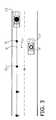
- FIG. 1is an elevation view of a host vehicle, and a remote vehicle communicatively coupled to the host vehicle, in accordance with a preferred embodiment of the present invention
- FIG. 1 ais an elevation view of the host and remote vehicles shown in FIG. 1 communicating through a third-party intermediary;
- FIG. 2is an elevation view of the dashboard of the host vehicle and collision control system shown in FIG. 1 , particularly illustrating a monitor, and map record;
- FIG. 2 ais an elevation view of the monitor displaying a divergence alert signal
- FIG. 2 bis an elevation view of the monitor displaying a directional alert signal
- FIG. 3is a plan view of a host vehicle and a remote vehicle traveling upon lanes of a multi-lane thoroughfare, particularly illustrating current position and trail coordinates, and a congruent path divergence by the host vehicle;
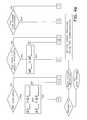
- FIG. 4is a flow diagram of a preferred method of performing the present invention, wherein non-compliant yaw rate, heading, and lateral distance discrepancies must be determined in order to detect a congruent path divergence;
- FIG. 4 ais a flow diagram of a second preferred method of performing the present invention, wherein the path divergence is determined by a weight factor, which is computed based on the availability/actuation of various system components, and the surpassing of discrepancy thresholds;
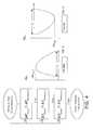
- FIG. 5is a line graph displaying a yaw rate discrepancy profile during a right congruent path divergence
- FIG. 6is a line graph displaying a yaw rate discrepancy profile during a left congruent path divergence.
- the present inventionconcerns a vehicle tracking system 10 adapted for use with a host vehicle 12 , and for alerting the operator 14 of a remote vehicle 16 .
- the system 10is illustrated and described herein with respect to vehicles, such as cars, SUV's, trucks, etc. However, it may also be utilized with airborne and watercraft vehicles, human motility, or other modes of transportation where path congruency is desired.
- the system 10is configured to determine a plurality of trail coordinates 12 t , and a current position coordinate 12 c for the host vehicle 12 , and a similar set of coordinates 16 t , and 16 c , for at least one remote vehicle 16 , as shown in FIG. 2 .
- the present inventionshall hereinafter be described with respect to a remote vehicle 16 , with the understanding that the inventive aspects of the invention may be concurrently performed with respect to a plurality of remote vehicles, wherein the results from each remote and host vehicle relationship may be further averaged or otherwise manipulated prior to achieving a final determination of host vehicle path divergence, if the remote vehicles 16 are also congruently traveling.
- an inventive aspect of the present inventionis the use of V2V communication technology to detect lane level relative positioning and determine congruent path divergence.
- the host vehicle 12 and remote vehicle 16are communicatively coupled by suitable wireless technology.
- the vehicles 12 , 16may be coupled by a radio local area network, RF technology, or other conventional means that enables inter-vehicle sharing of information in real-time.
- the vehicles 12 , 16may be communicatively coupled through an intermediary third-party 18 (see, FIG. 1 a ) that continuously collects the relevant position data, performs the determinations described herein, and transmits an alert of a congruent path divergence back to the remote vehicle 16 .
- the reliability of the safety applicationdepends on the accuracy of the V2V communication system involved.
- a locator device 20is adapted for use by the host and remote vehicles 12 , 16 .
- the device 20is configured to determine and store or caused to be stored for at least a period the current position coordinates, and pluralities of trail coordinates for the host and remote vehicles 12 , 16 .
- a preferred locator device 20is configured to determine longitude, latitude, and more preferably, height coordinates, using GPS; and as such, further includes a GPS receiver 22 within each vehicle 12 , 16 , and at least four mapped satellites 24 , 26 , 28 , 30 communicatively coupled and configured to deliver separate transmission signals to each receiver 22 at all times.
- MGRSMilitary Grid Reference System
- ECEF X, Y, ZECEF X, Y, Z
- the preferred system 10is adapted for use with a conventional navigation system so as to enable visual perception of a detected congruent path divergence (or lane-change, as shown in the illustrated embodiment) by the operator 14 .
- the preferred locator device 20also includes map databases 32 preferably housed within the remote and host vehicle 12 , 16 .
- Each database 32has at least one map record 32 a consisting of global positioning points.
- the device 20is configured to match the host and remote current position and trail coordinates to corresponding points on the map record 32 a .
- the preferred system 10further includes a monitor 34 that is communicatively coupled to the database 32 and device 20 , and configured to display the map record 32 a and coordinates.
- the database 32may be stored by conventional storage means, such as CD-ROM, internal hard disk, and removable memory cards.
- the inventive system 10is configured to autonomously determine, and communicate (i.e. without operator participation) to the remote vehicle 16 , the occurrence of a path divergence by the host vehicle 12 .
- the inventive algorithmsare based on sets of current position and trail coordinates of the vehicles 12 , 16 , and on data values of at least one condition existent to both vehicles at each of the set of coordinates.
- each of the vehicles 12 , 16includes at least one sensor 36 configured to determine and cause to be stored data values of at least one condition.
- each vehicle 12 , 16is equipped with a yaw gyro operable to detect the instantaneous yaw rate, v, of the measuring vehicle at each position.
- each vehicle 12 , 16may further include a steering angle sensor, operable to detect the angle of rotation of the steering wheel.
- the preferred sensor 36may also include memory capabilities, so as to store the data values itself.
- a controller 38is communicatively coupled to the device 20 , and the remote vehicle 16 , so as to receive position and condition data from the remote vehicle 16 through the V2V communication system.
- the preferred controller 38is programmably configured to further determine similar host vehicle data, and more preferably, compute data values of additional desirous conditions in path divergence determination.
- the controller 38is configured to receive the yaw rates (or steering angles, if available), and coordinates, and to determine a heading, h, for each of the host and remote vehicle 12 , 16 , based on their respective coordinates, and yaw rates.
- the preferred controller 38is configured to generate an audible, visible and/or haptic (e.g., a gentle seat vibration in the corresponding side) alert 34 a at the remote vehicle (see, FIGS. 2 a , and b ), when a host vehicle path divergence is determined. More particularly, the preferred controller 38 is configured to generate the alert when the condition deviates greater than a minimum threshold. More preferably, one of a plurality of alerts that convey varying degrees of deviation and corresponds to one of a plurality of thresholds, may be produced as further described herein. For example, a plurality of alerts may vary in indicia, color, pitch, loudness, location, font, verbiage, flashing rates, etc.
- an exemplary collision detection signal 34 amay include the intermittent display of indicia, such as “TRAIL VEHICLE LANE CHANGE” on the monitor 34 .
- an exemplary path divergence alert 34 bmay be a display of one of a plurality of arrows that direct the operator 14 towards the direction of the path divergence, i.e. left or right.
- the signals 34 a,bare provided for a predetermined and preferably modifiable period, sufficient to alert the operator 14 satisfactorily.
- the preferred system 10is configured to initially determine the relative positioning of the host and remote vehicles.
- a preferred methodutilizes the current position and trail coordinates, yaw rates, and more preferably, the headings of the host and remote vehicles 12 , 16 to determine a congruently traveling remote vehicles 16 .
- a preferred embodiment of the inventive algorithms and programmed functions of the controller 38 to determine a congruent path divergenceis more particularly described as follows:
- Remote vehicles 16 traveling in the same direction with the host vehicle 12are determined by comparing the relative headings.
- Inequality (1)yields the subset of such vehicles: Cos ⁇ h Cos ⁇ s +Sin ⁇ h Sin ⁇ s >0.5 (1) wherein ⁇ h is the host vehicle heading at a time, t, ⁇ s is the remote vehicle heading, and a true value for the inequality yields a same relative direction of travel. Conversely, a sum of the products less than 0.5 yields an opposite relative direction of travel for the host and remote vehicles 12 , 16 .
- the host vehicle heading ⁇ his preferably set to zero for the chosen coordinate system, so that inequality (1) becomes Sin ⁇ h Sin ⁇ s >0.5.
- Remote vehicles traveling upon the same thoroughfare as, within the V2V range of, but in the opposite direction to the host vehicle 12are not further considered by the system 10 . II. Classify Vehicles Traveling in the Same Direction into Lane Level Traffic
- Remote vehicles 16 traveling in the generally same direction as the host vehicle 12are categorized in one of a plurality of relative positions by comparing the current position coordinates of the host and remote vehicles 12 , 16 . By considering the host vehicle heading, these remote vehicles 16 may initially be separated into “arrear” and “ahead” (or preceding) sets, wherein generally arrear remote vehicles 16 are determined when the host vehicle acts to increase the distance between the two.
- remote vehicles 16 located arrear of the host vehicle 12are computationally determined by inequality (2): ( x s ⁇ x h )Cos ⁇ h +( y s ⁇ y h )Sin ⁇ h ⁇ 0 (2), wherein x s ,y s are coordinates of the remote vehicle 16 , and x h ,y h are coordinates of the host vehicle 12 .
- a sum of the products greater than zero (>0)results when the remote vehicle 16 is located ahead of the host vehicles 12 . It is appreciated, however, that height coordinates, z x , are not considered, so as to present a simplified planar analysis.
- relative lane positioncan be determined by computing a lateral offset between the trails and current position coordinates of the host and remote vehicles 12 , 16 at the beginning time, t, of the sample period.
- thresholdscan be used to define lane offsets. For example, a lateral offset between negative one and positive one may indicate that the host and remote vehicles 12 , 16 share the same lane.
- the extrapolated pointis trigonometrically determined from the two most proximate remote vehicle trail coordinates and the current host vehicle position.
- the estimated condition values at Nare also extrapolated from the yaw rates, and headings at the two most proximate remote vehicle trail coordinates.
- the host vehicle 12maintains a congruent path, when its condition data values generally match (i.e. are within acceptable measurement and sensory error limits) remote vehicle condition data values at the extrapolated positions.
- the host vehicle 12may be configured to autonomously determine whether a trailing remote vehicle and the host vehicle 12 have congruent paths, and deliver a message to the trailing remote vehicle instructing it to monitor and communicate the existence of a path divergence, so that the host vehicle 12 becomes a remote vehicle 16 as described herein.
- the operators of the two vehiclesmay manually establish such a relationship.
- path divergenceis monitored by determining the difference (or discrepancy) between the condition data value at the current host vehicle position, and the extrapolated remote vehicle trail position, ⁇ v H , and comparing the discrepancy to a predetermined threshold (e.g. a yaw rate difference of greater than 10%). Where the discrepancy exceeds the condition threshold configured to tolerate natural in-lane path fluctuations, a divergence is realized.
- a predetermined thresholde.g. a yaw rate difference of greater than 10%
- the system 10is configured to sense and determine a plurality of matching conditions (e.g. yaw rate, heading, and lateral distance), and determine a discrepancy for each.
- a divergence in this configurationresults only where each condition discrepancy exceeds its corresponding threshold.
- multiple condition analysismay be configured to provide redundancy by considering them alternatively, or in parallel.
- a routinemay be utilized, that attributes +1, 0, or ⁇ 1 points to a weight factor depending upon the availability/actuation of a GPS system, a yaw rate sensor, a steering angle sensor, and turn signal activation sensor, and whether or not a discrepancy threshold has been surpassed. As shown in FIG.
- such a routinemay be configured to attribute less weight to related thresholds, by requiring the satisfaction of both prior to attributing a point, and to determine and alert other vehicles of a path divergence, where the total weight factor is greater than two.
- the preferred thresholdsare variable according to user preference, and/or application.
- the system 10is configured to determine a condition discrepancy at a plurality of current host vehicle positions during a sampling period, wherein said period extends from a beginning time, t, through a termination time T L , so as to form a discrepancy profile.
- the total cumulative value of discrepancies for a given conditionis determined according to the following formulas:
- each total discrepancyis preferably compared to a corresponding total cumulative threshold in order to determine a path divergence. It is appreciated that utilizing a multi-entry or cumulative method reduces the chances of an alert being produced based on a single anomalistic data entry.
- the variation of the change in the condition data valuesuch as the yaw rate, ⁇ v H , during a path divergence (or lane change) period, presents the path divergence profile.
- the rate of change in the condition, ⁇ v His presented by the steepness of the profile.
- a plurality of divergence categoriescan be distinguished according to the rate of change by analyzing the profile. For example, a sharp versus gradual divergence can be determined and alerted to the remote vehicle 16 ; wherein smaller periods, T L , and greater maximums or peaks, ⁇ v H max , indicate sharp (sudden) divergences, and larger T L 's and smaller ⁇ v H max 's indicate smooth divergences.
- FIGS. 5 and 6further categorization with respect to the direction of the divergence can be discerned from the profile, as shown in FIGS. 5 and 6 .
- the sign of ⁇ v Hindicates the divergence direction (e.g. a right or left turn); wherein positive profiles represent right divergences (see, FIG. 5 ), and negative profiles represent left divergences (see, FIG. 6 ).
Landscapes
- Engineering & Computer Science (AREA)
- Transportation (AREA)
- Mechanical Engineering (AREA)
- Physics & Mathematics (AREA)
- General Physics & Mathematics (AREA)
- Traffic Control Systems (AREA)
Abstract
Description
Cos θhCos θs+Sin θhSin θs>0.5 (1)
wherein θhis the host vehicle heading at a time, t, θsis the remote vehicle heading, and a true value for the inequality yields a same relative direction of travel. Conversely, a sum of the products less than 0.5 yields an opposite relative direction of travel for the host and
II. Classify Vehicles Traveling in the Same Direction into Lane Level Traffic
(xs−xh)Cos θh+(ys−yh)Sin θh<0 (2),
wherein xs,ysare coordinates of the
δrH=((xH−xN)2+(yH−yN)2)0.5−rt (3),
where rtis the minimum distance taken at the beginning of the sampling period.
(δvPj/(Pj+1)(Pj))(Pj+1N) (4),
wherein (Pj+1)(Pj) is the linear distance between the two most proximate trail coordinates, and Pj+1N is the linear distance between the extrapolated point and trail position Pj+1. Thus, in this configuration, the estimated yaw rate, and likewise heading, at the extrapolated position, N, are determinable as follows:
vN=vPj+1+δvN (5), and
hN=hPj+1+δhN (6).
III. Detecting Congruent Path Divergence (Lane Change)
Thus, each total discrepancy is preferably compared to a corresponding total cumulative threshold in order to determine a path divergence. It is appreciated that utilizing a multi-entry or cumulative method reduces the chances of an alert being produced based on a single anomalistic data entry.
IV. Lane Changing Profile (Signature)
Claims (17)
(Δ(data value)Pj/Pj+1Pj)(Pj+1N),
Priority Applications (3)
| Application Number | Priority Date | Filing Date | Title |
|---|---|---|---|
| US11/436,497US7920969B2 (en) | 2005-08-18 | 2006-05-18 | System for and method of determining a host vehicle lane change |
| DE102006038160.2ADE102006038160B4 (en) | 2005-08-18 | 2006-08-16 | System and method for determining a lane change of a host vehicle |
| JP2006223394AJP2007095038A (en) | 2005-08-18 | 2006-08-18 | System and method for determining host lane |
Applications Claiming Priority (2)
| Application Number | Priority Date | Filing Date | Title |
|---|---|---|---|
| US11/207,168US7729857B2 (en) | 2005-08-18 | 2005-08-18 | System for and method of detecting a collision and predicting a vehicle path |
| US11/436,497US7920969B2 (en) | 2005-08-18 | 2006-05-18 | System for and method of determining a host vehicle lane change |
Related Parent Applications (1)
| Application Number | Title | Priority Date | Filing Date |
|---|---|---|---|
| US11/207,168Continuation-In-PartUS7729857B2 (en) | 2005-08-18 | 2005-08-18 | System for and method of detecting a collision and predicting a vehicle path |
Publications (2)
| Publication Number | Publication Date |
|---|---|
| US20070043506A1 US20070043506A1 (en) | 2007-02-22 |
| US7920969B2true US7920969B2 (en) | 2011-04-05 |
Family
ID=37737980
Family Applications (2)
| Application Number | Title | Priority Date | Filing Date |
|---|---|---|---|
| US11/207,168Active2029-04-01US7729857B2 (en) | 2005-08-18 | 2005-08-18 | System for and method of detecting a collision and predicting a vehicle path |
| US11/436,497Expired - Fee RelatedUS7920969B2 (en) | 2005-08-18 | 2006-05-18 | System for and method of determining a host vehicle lane change |
Family Applications Before (1)
| Application Number | Title | Priority Date | Filing Date |
|---|---|---|---|
| US11/207,168Active2029-04-01US7729857B2 (en) | 2005-08-18 | 2005-08-18 | System for and method of detecting a collision and predicting a vehicle path |
Country Status (3)
| Country | Link |
|---|---|
| US (2) | US7729857B2 (en) |
| CN (1) | CN100555357C (en) |
| DE (1) | DE102006037993B4 (en) |
Cited By (24)
| Publication number | Priority date | Publication date | Assignee | Title |
|---|---|---|---|---|
| US20100245123A1 (en)* | 2009-03-27 | 2010-09-30 | Ford Global Technologies, Llc | Telematics system and method for traction reporting and control in a vehicle |
| US20120029813A1 (en)* | 2009-06-11 | 2012-02-02 | Toyota Jidosha Kabushiki Kaisha | Method for judging vehicle traveling position and vehicle traveling position judgment device |
| US20120206275A1 (en)* | 2011-02-10 | 2012-08-16 | Hans-Peter Mauderer | Blind area warning for vehicles |
| US8335643B2 (en) | 2010-08-10 | 2012-12-18 | Ford Global Technologies, Llc | Point of interest search, identification, and navigation |
| US20130030687A1 (en)* | 2010-04-12 | 2013-01-31 | Toyota Jidosha Kabushiki Kaisha | On-vehicle apparatus, preceding vehicle position determining apparatus, and preceding vehicle position determining method |
| US8483958B2 (en) | 2010-12-20 | 2013-07-09 | Ford Global Technologies, Llc | User configurable onboard navigation system crossroad presentation |
| US8521424B2 (en) | 2010-09-29 | 2013-08-27 | Ford Global Technologies, Llc | Advanced map information delivery, processing and updating |
| US8688321B2 (en) | 2011-07-11 | 2014-04-01 | Ford Global Technologies, Llc | Traffic density estimation |
| US8731814B2 (en) | 2010-07-02 | 2014-05-20 | Ford Global Technologies, Llc | Multi-modal navigation system and method |
| US8838385B2 (en) | 2011-12-20 | 2014-09-16 | Ford Global Technologies, Llc | Method and apparatus for vehicle routing |
| US8849552B2 (en) | 2010-09-29 | 2014-09-30 | Ford Global Technologies, Llc | Advanced map information delivery, processing and updating |
| US8977479B2 (en) | 2013-03-12 | 2015-03-10 | Ford Global Technologies, Llc | Method and apparatus for determining traffic conditions |
| US9047774B2 (en) | 2013-03-12 | 2015-06-02 | Ford Global Technologies, Llc | Method and apparatus for crowd-sourced traffic reporting |
| US9713963B2 (en) | 2013-02-18 | 2017-07-25 | Ford Global Technologies, Llc | Method and apparatus for route completion likelihood display |
| US9846046B2 (en) | 2010-07-30 | 2017-12-19 | Ford Global Technologies, Llc | Vehicle navigation method and system |
| US9863777B2 (en) | 2013-02-25 | 2018-01-09 | Ford Global Technologies, Llc | Method and apparatus for automatic estimated time of arrival calculation and provision |
| US9874452B2 (en) | 2013-03-14 | 2018-01-23 | Ford Global Technologies, Llc | Method and apparatus for enhanced driving experience including dynamic POI identification |
| US10094906B2 (en) | 2016-12-22 | 2018-10-09 | GM Global Technology Operations LLC | Vehicle positioning system using V2X, sensor, and GNSS information |
| US10173674B2 (en) | 2016-06-15 | 2019-01-08 | Ford Global Technologies, Llc | Traction based systems and methods |
| US10276043B2 (en) | 2016-12-22 | 2019-04-30 | GM Global Technology Operations LLC | Vehicle system using vehicle-to-infrastructure and sensor information |
| US11097735B1 (en) | 2020-03-19 | 2021-08-24 | Toyota Motor North America, Inc. | Transport lane usage |
| US11488424B2 (en) | 2020-03-19 | 2022-11-01 | Toyota Motor North America, Inc. | Motion-based transport assessment |
| US11720114B2 (en) | 2020-03-19 | 2023-08-08 | Toyota Motor North America, Inc. | Safety of transport maneuvering |
| US11747806B1 (en) | 2019-02-05 | 2023-09-05 | AV-Connect, Inc. | Systems for and method of connecting, controlling, and coordinating movements of autonomous vehicles and other actors |
Families Citing this family (147)
| Publication number | Priority date | Publication date | Assignee | Title |
|---|---|---|---|---|
| DE102006011481A1 (en)* | 2006-03-13 | 2007-09-20 | Robert Bosch Gmbh | A method and apparatus for assisting in guiding a vehicle |
| JP4906398B2 (en)* | 2006-05-15 | 2012-03-28 | アルパイン株式会社 | In-vehicle road shape identification device, in-vehicle system, road shape identification method and periphery monitoring method |
| JP4793094B2 (en)* | 2006-05-17 | 2011-10-12 | 株式会社デンソー | Driving environment recognition device |
| DE102006038018A1 (en)* | 2006-08-14 | 2008-02-21 | Robert Bosch Gmbh | A driver assistance method and apparatus by generating lane information to support or replace lane information of a video-based lane information facility |
| US7813877B2 (en)* | 2006-10-30 | 2010-10-12 | Toyota Motor Engineering & Manufacturing North America, Inc. | Relevancy check for vehicle safety messages using a path history |
| JP4254844B2 (en)* | 2006-11-01 | 2009-04-15 | トヨタ自動車株式会社 | Travel control plan evaluation device |
| WO2008056416A1 (en)* | 2006-11-09 | 2008-05-15 | Fujitsu Limited | Wireless communication apparatus and wireless communication method |
| JP4400634B2 (en)* | 2007-02-28 | 2010-01-20 | トヨタ自動車株式会社 | Collision prediction device |
| JPWO2008146507A1 (en)* | 2007-05-25 | 2010-08-19 | 本田技研工業株式会社 | Vehicle driving support device and driving support system |
| JP4207088B2 (en)* | 2007-06-20 | 2009-01-14 | トヨタ自動車株式会社 | Vehicle travel estimation device |
| CN101101702A (en)* | 2007-07-16 | 2008-01-09 | 陈拙夫 | Inter-vehicle information sharing automatic driving system and control method thereof |
| US20090119014A1 (en)* | 2007-11-07 | 2009-05-07 | Seth Caplan | Navigation system for alerting drivers of nearby vehicles |
| JP5309633B2 (en)* | 2007-11-16 | 2013-10-09 | アイシン・エィ・ダブリュ株式会社 | Vehicle control apparatus, vehicle control method, and computer program |
| US7545261B1 (en)* | 2008-09-02 | 2009-06-09 | International Business Machines Corporation | Passive method and apparatus for alerting a driver of a vehicle of a potential collision condition |
| DE102008042565A1 (en)* | 2008-10-02 | 2010-04-08 | Robert Bosch Gmbh | Method for operating a driver assistance device |
| US20100152967A1 (en)* | 2008-12-15 | 2010-06-17 | Delphi Technologies, Inc. | Object detection system with learned position information and method |
| DE112008004069B4 (en)* | 2008-12-18 | 2014-09-04 | Toyota Jidosha Kabushiki Kaisha | radar system |
| US8818703B2 (en)* | 2009-01-29 | 2014-08-26 | Toyota Jidosha Kabushiki Kaisha | Object recognition device and object recognition method |
| DE102009015540A1 (en)* | 2009-04-01 | 2010-10-14 | Siemens Aktiengesellschaft | Method and device for speed monitoring |
| DE112009004844B4 (en)* | 2009-06-02 | 2015-05-13 | Toyota Jidosha Kabushiki Kaisha | VEHICLE MONITORING DEVICE ENVIRONMENT |
| DE102009028279A1 (en) | 2009-08-06 | 2011-02-10 | Robert Bosch Gmbh | Method for setting an influencing the driving dynamics of a vehicle actuator |
| CN101727758B (en)* | 2009-12-15 | 2011-06-29 | 浙江工业大学 | A method for transmitting vehicle danger warning information based on short-range wireless communication |
| DE102010011497A1 (en)* | 2010-03-16 | 2011-09-22 | GM Global Technology Operations LLC , (n. d. Ges. d. Staates Delaware) | Method for avoiding or mitigating a collision, control device for a driver assistance system and vehicle |
| DE102010003760A1 (en)* | 2010-04-08 | 2011-10-13 | Robert Bosch Gmbh | Method for operating distance management of vehicle with electromotive drive based on power consumption model of vehicle, involves running range estimation of driving route by vehicle |
| US20110250836A1 (en)* | 2010-04-09 | 2011-10-13 | Telcordia Technologies, Inc. | Interference-adaptive uwb radio-based vehicle communication system for active-safety |
| CN101813492B (en)* | 2010-04-19 | 2012-11-14 | 清华大学 | Vehicle navigation system and method |
| DE102010044631B4 (en)* | 2010-09-07 | 2025-10-09 | Volkswagen Ag | Method for determining the collision probability of a motor vehicle |
| US8604918B2 (en)* | 2010-11-10 | 2013-12-10 | Hyundai Motor Company | System and method for detecting a vehicle in the vicinity by using wireless communication |
| CN102529962B (en)* | 2010-12-08 | 2014-11-05 | 安尼株式会社 | Mobile body anti-collision device and mobile body |
| EP2508956B1 (en)* | 2011-04-06 | 2013-10-30 | Kollmorgen Särö AB | A collision avoiding method and system |
| US8849483B2 (en)* | 2011-04-13 | 2014-09-30 | California Institute Of Technology | Target trailing with safe navigation with colregs for maritime autonomous surface vehicles |
| US9581997B1 (en)* | 2011-04-22 | 2017-02-28 | Angel A. Penilla | Method and system for cloud-based communication for automatic driverless movement |
| DE102011018571A1 (en)* | 2011-04-26 | 2012-10-31 | Continental Automotive Gmbh | Method for checking communication messages in the vehicle-to-environment communication and suitable receivers |
| CN102768795B (en)* | 2011-05-05 | 2014-07-09 | 李志恒 | System and method for commanding and dispatching leading vehicle of guard vehicle platoon based on JTDDS algorithm |
| US8466807B2 (en)* | 2011-06-01 | 2013-06-18 | GM Global Technology Operations LLC | Fast collision detection technique for connected autonomous and manual vehicles |
| US8842021B2 (en)* | 2011-06-07 | 2014-09-23 | International Business Machines Corporation | Methods and systems for early warning detection of emergency vehicles |
| US10520581B2 (en) | 2011-07-06 | 2019-12-31 | Peloton Technology, Inc. | Sensor fusion for autonomous or partially autonomous vehicle control |
| US10520952B1 (en) | 2011-07-06 | 2019-12-31 | Peloton Technology, Inc. | Devices, systems, and methods for transmitting vehicle data |
| US11334092B2 (en)* | 2011-07-06 | 2022-05-17 | Peloton Technology, Inc. | Devices, systems, and methods for transmitting vehicle data |
| US9582006B2 (en) | 2011-07-06 | 2017-02-28 | Peloton Technology, Inc. | Systems and methods for semi-autonomous convoying of vehicles |
| WO2018039114A1 (en)* | 2016-08-22 | 2018-03-01 | Peloton Technology, Inc. | Systems for vehicular platooning and methods therefor |
| US20170242443A1 (en) | 2015-11-02 | 2017-08-24 | Peloton Technology, Inc. | Gap measurement for vehicle convoying |
| US8799201B2 (en) | 2011-07-25 | 2014-08-05 | Toyota Motor Engineering & Manufacturing North America, Inc. | Method and system for tracking objects |
| US9165470B2 (en)* | 2011-07-25 | 2015-10-20 | GM Global Technology Operations LLC | Autonomous convoying technique for vehicles |
| EP2750118B1 (en)* | 2011-08-26 | 2020-01-01 | Toyota Jidosha Kabushiki Kaisha | Driving support apparatus and driving support method |
| CN102568195A (en)* | 2011-12-29 | 2012-07-11 | 上海顶竹通讯技术有限公司 | Method and system for pre-judging vehicle running track |
| CN102521975B (en)* | 2011-12-31 | 2013-09-04 | 姜廷顺 | System and method capable of guiding leading vehicle to accurately fulfill guard task |
| KR20140107619A (en)* | 2012-01-26 | 2014-09-04 | 도요타 지도샤(주) | Object recognition device and vehicle control device |
| US20130289824A1 (en)* | 2012-04-30 | 2013-10-31 | GM Global Technology Operations LLC | Vehicle turn assist system and method |
| DE102012208646A1 (en)* | 2012-05-23 | 2013-11-28 | Siemens Aktiengesellschaft | Method for communication within an ad-hoc cooperating, in particular wireless, motor vehicle communication system, installation of the traffic infrastructure and traffic participant device |
| US9026367B2 (en)* | 2012-06-27 | 2015-05-05 | Microsoft Technology Licensing, Llc | Dynamic destination navigation system |
| US20140071282A1 (en)* | 2012-09-13 | 2014-03-13 | GM Global Technology Operations LLC | Alert systems and methods using real-time lane information |
| DE102012021282A1 (en)* | 2012-10-29 | 2014-04-30 | Audi Ag | Method for coordinating the operation of fully automated moving vehicles |
| EP2918467A4 (en)* | 2012-11-08 | 2016-06-08 | Toyota Motor Co Ltd | DRIVING ASSIST DEVICE AND METHOD, COLLISION PREDICTION DEVICE AND METHOD, AND ALERT DEVICE AND METHOD |
| CN104755344B (en)* | 2012-11-27 | 2016-05-04 | 日产自动车株式会社 | Vehicle acceleration suppressing device and vehicle acceleration suppressing method |
| JP5761162B2 (en) | 2012-11-30 | 2015-08-12 | トヨタ自動車株式会社 | Vehicle position estimation device |
| US20180210463A1 (en) | 2013-03-15 | 2018-07-26 | Peloton Technology, Inc. | System and method for implementing pre-cognition braking and/or avoiding or mitigation risks among platooning vehicles |
| US11294396B2 (en) | 2013-03-15 | 2022-04-05 | Peloton Technology, Inc. | System and method for implementing pre-cognition braking and/or avoiding or mitigation risks among platooning vehicles |
| CN103241243B (en)* | 2013-05-15 | 2016-09-14 | 奇瑞汽车股份有限公司 | A kind of method and apparatus determining vehicle-state |
| FR3006487B1 (en)* | 2013-05-28 | 2016-12-02 | Peugeot Citroen Automobiles Sa | METHOD AND COMMUNICATION DEVICE FOR BYPASSING A CIRCULATION PATH |
| DE102013219414A1 (en)* | 2013-09-26 | 2015-03-26 | Bayerische Motoren Werke Aktiengesellschaft | Method and device for providing predictive vehicle movement information for a driver assistance system of a vehicle |
| US9305323B2 (en) | 2013-09-30 | 2016-04-05 | Motorola Solutions, Inc. | Communication system for detecting law enforcement violations in a vehicular environment |
| CN104661179B (en)* | 2013-11-20 | 2019-07-05 | 沈阳晨讯希姆通科技有限公司 | Location data sharing method and system |
| CN104680838B (en)* | 2013-11-28 | 2017-10-10 | 三星电子(中国)研发中心 | Safe householder method and system for automobile |
| GB2521415B (en) | 2013-12-19 | 2020-03-04 | Here Global Bv | An apparatus, method and computer program for controlling a vehicle |
| DE102014200638A1 (en)* | 2014-01-16 | 2015-07-30 | Bayerische Motoren Werke Aktiengesellschaft | Method and system for estimating a lane course |
| JP5991340B2 (en)* | 2014-04-28 | 2016-09-14 | トヨタ自動車株式会社 | Driving assistance device |
| US9460624B2 (en) | 2014-05-06 | 2016-10-04 | Toyota Motor Engineering & Manufacturing North America, Inc. | Method and apparatus for determining lane identification in a roadway |
| CN103971541B (en)* | 2014-05-19 | 2016-02-24 | 上海扬梓投资管理有限公司 | Vehicle collision avoidance safety alarm method and device |
| CN105303886B (en)* | 2014-06-17 | 2019-02-05 | 中国移动通信集团公司 | Early warning processing method, device, terminal and early warning server of traffic information |
| CN104574940A (en)* | 2014-08-08 | 2015-04-29 | 北京易华录信息技术股份有限公司 | Method and system capable of enabling leader car to run exactly by second according to time table |
| CN104574941B (en)* | 2014-08-11 | 2017-09-29 | 北京易华录信息技术股份有限公司 | Guide-car is accurate to the method and system of second operation according to guard duty route before guiding |
| CN104599487B (en)* | 2014-08-12 | 2017-07-07 | 北京易华录信息技术股份有限公司 | The preceding guide-car of guiding is accurate to the method and system for arriving at the second when GPS is blocked |
| CN104157167B (en)* | 2014-08-28 | 2016-09-28 | 银江股份有限公司 | A kind of vehicle collision avoidance method based on collaborative relative localization technology |
| CN104331936A (en)* | 2014-10-28 | 2015-02-04 | 奇瑞汽车股份有限公司 | Expressway electronic toll collection (ETC) system and method based on vehicle networking technology |
| EP3218888B1 (en)* | 2014-11-11 | 2020-03-25 | Harman International Industries, Incorporated | Trajectory detection |
| KR101610544B1 (en) | 2014-11-21 | 2016-04-07 | 현대자동차주식회사 | System and method for autonomous driving of vehicle |
| JP6079767B2 (en)* | 2014-12-15 | 2017-02-15 | トヨタ自動車株式会社 | Alarm device |
| CN104537889B (en)* | 2014-12-30 | 2017-03-01 | 四川九洲电器集团有限责任公司 | A kind of avoiding collision under difference vehicle condition and system |
| US11167755B2 (en) | 2015-02-07 | 2021-11-09 | Hella Kgaa Hueck & Co. | Method for at least partially automatically controlling a motor vehicle |
| DE102015001638A1 (en)* | 2015-02-07 | 2016-08-11 | Hella Kgaa Hueck & Co. | Method for the at least partially independent control of a motor vehicle |
| JP6437629B2 (en)* | 2015-03-03 | 2018-12-12 | パイオニア株式会社 | Route search apparatus, control method, program, and storage medium |
| KR101675306B1 (en)* | 2015-03-20 | 2016-11-11 | 현대자동차주식회사 | Accident information manage apparatus, vehicle having the same and method for managing accident information |
| DE102015004748A1 (en) | 2015-04-11 | 2016-10-13 | Audi Ag | Method for predicting a dangerous driving situation |
| JP6553930B2 (en)* | 2015-04-14 | 2019-07-31 | 日立オートモティブシステムズ株式会社 | Vehicle information processing apparatus and vehicle information processing program |
| CN104851320A (en)* | 2015-04-28 | 2015-08-19 | 奇瑞汽车股份有限公司 | Method and device for prompting driver |
| US9776528B2 (en) | 2015-06-17 | 2017-10-03 | Nissan North America, Inc. | Electric vehicle range prediction |
| US20220377549A9 (en)* | 2015-06-30 | 2022-11-24 | Apple Inc. | Proxy coordinated wireless communication operation for vehicular environments |
| WO2017002258A1 (en)* | 2015-07-02 | 2017-01-05 | 三菱電機株式会社 | Route prediction device |
| US9574964B2 (en)* | 2015-07-07 | 2017-02-21 | Toyota Jidosha Kabushiki Kaisha | Mobile computer atmospheric barometric pressure system |
| US9922565B2 (en)* | 2015-07-20 | 2018-03-20 | Dura Operating Llc | Sensor fusion of camera and V2V data for vehicles |
| US20170021863A1 (en)* | 2015-07-20 | 2017-01-26 | Dura Operating, Llc | System and method for verifying road position information for a motor vehicle |
| US10282997B2 (en) | 2015-07-20 | 2019-05-07 | Dura Operating, Llc | System and method for generating and communicating lane information from a host vehicle to a vehicle-to-vehicle network |
| US9618347B2 (en)* | 2015-08-03 | 2017-04-11 | Nissan North America, Inc. | Projecting vehicle transportation network information representing an intersection |
| US10460534B1 (en) | 2015-10-26 | 2019-10-29 | Allstate Insurance Company | Vehicle-to-vehicle accident detection |
| US10152882B2 (en)* | 2015-11-30 | 2018-12-11 | Nissan North America, Inc. | Host vehicle operation using remote vehicle intention prediction |
| KR101886483B1 (en)* | 2015-12-08 | 2018-08-07 | 현대자동차주식회사 | Method for classify Target using Path History Data at V2V |
| US10486707B2 (en)* | 2016-01-06 | 2019-11-26 | GM Global Technology Operations LLC | Prediction of driver intent at intersection |
| US10030978B2 (en) | 2016-01-17 | 2018-07-24 | Toyota Motor Engineering & Manufacturing North America, Inc. | System and method for detection of surrounding vehicle lane departure |
| US9632507B1 (en) | 2016-01-29 | 2017-04-25 | Meritor Wabco Vehicle Control Systems | System and method for adjusting vehicle platoon distances based on predicted external perturbations |
| JP6323473B2 (en)* | 2016-02-25 | 2018-05-16 | トヨタ自動車株式会社 | Travel control device |
| JP7005526B2 (en) | 2016-05-31 | 2022-01-21 | ぺロトン テクノロジー インコーポレイテッド | State machine of platooning controller |
| DE102016009760A1 (en)* | 2016-08-11 | 2018-02-15 | Trw Automotive Gmbh | Control system and control method for guiding a motor vehicle along a path |
| US10139244B2 (en)* | 2016-08-17 | 2018-11-27 | Veoneer Us Inc. | ADAS horizon and vision supplemental V2X |
| US10369998B2 (en) | 2016-08-22 | 2019-08-06 | Peloton Technology, Inc. | Dynamic gap control for automated driving |
| US10089875B2 (en)* | 2016-09-06 | 2018-10-02 | Delphi Technologies, Inc. | Automated vehicle cross-traffic detection system |
| US10377376B2 (en)* | 2016-10-06 | 2019-08-13 | Ford Global Technologies, Llc | Vehicle with environmental context analysis |
| JP6609237B2 (en)* | 2016-11-17 | 2019-11-20 | 株式会社デンソー | Collision determination device and collision determination method |
| JP6551384B2 (en)* | 2016-12-26 | 2019-07-31 | トヨタ自動車株式会社 | Vehicle alert device |
| CN106960588B (en)* | 2017-03-24 | 2019-08-06 | 奇瑞汽车股份有限公司 | Method and device is determined based on the vehicle attitude of dedicated short-range communication |
| CA3236625A1 (en) | 2017-04-12 | 2018-10-18 | Lawrence Livermore National Security, Llc | Swarm path planner system for vehicles |
| CA3094649C (en) | 2017-04-12 | 2023-03-28 | David W. Paglieroni | Attract-repel path planner system for collision avoidance |
| CN109389864A (en)* | 2017-08-09 | 2019-02-26 | 湖南大学 | A kind of vehicle relative positioning and anti-collision warning method |
| US10229590B2 (en)* | 2017-08-14 | 2019-03-12 | GM Global Technology Operations LLC | System and method for improved obstable awareness in using a V2X communications system |
| US10636307B2 (en)* | 2017-09-20 | 2020-04-28 | The Boeing Company | Broadcasting system for autonomous vehicles |
| DE102017217091B4 (en)* | 2017-09-26 | 2022-11-24 | Ford Global Technologies, Llc | Method for assisting a driver in staying in lane |
| US10657811B2 (en) | 2017-10-04 | 2020-05-19 | Toyota Motor Engineering & Manufacturing North America, Inc. | Travel lane identification without road curvature data |
| US10668922B2 (en) | 2017-10-04 | 2020-06-02 | Toyota Motor Engineering & Manufacturing North America, Inc. | Travel lane identification without road curvature data |
| CN108022450B (en)* | 2017-10-31 | 2020-07-21 | 华为技术有限公司 | A kind of assisted driving method and traffic control unit based on cellular network |
| US11232350B2 (en)* | 2017-11-29 | 2022-01-25 | Honda Motor Co., Ltd. | System and method for providing road user classification training using a vehicle communications network |
| CN108646264B (en)* | 2018-05-10 | 2021-10-01 | 上海安吉星信息服务有限公司 | A vehicle positioning method and device |
| US10899323B2 (en) | 2018-07-08 | 2021-01-26 | Peloton Technology, Inc. | Devices, systems, and methods for vehicle braking |
| CN109017781B (en)* | 2018-08-17 | 2020-07-31 | 李俊宏 | Vehicle auxiliary or automatic driving method and system based on road resources |
| CN109116867B (en)* | 2018-09-28 | 2020-04-14 | 拓攻(南京)机器人有限公司 | Unmanned aerial vehicle flight obstacle avoidance method and device, electronic equipment and storage medium |
| US10762791B2 (en) | 2018-10-29 | 2020-09-01 | Peloton Technology, Inc. | Systems and methods for managing communications between vehicles |
| US10553117B1 (en) | 2018-11-06 | 2020-02-04 | Toyota Motor Engineering & Manufacturing North America, Inc. | System and method for determining lane occupancy of surrounding vehicles |
| US10845197B2 (en)* | 2018-11-27 | 2020-11-24 | Aptiv Technologies Limited | Dead-reckoning guidance system and method with cardinal-direction based coordinate-corrections |
| KR102668309B1 (en)* | 2018-12-18 | 2024-05-29 | 현대자동차주식회사 | Autonomous vehicle and driving control method using the same |
| US10627823B1 (en)* | 2019-01-30 | 2020-04-21 | StradVision, Inc. | Method and device for performing multiple agent sensor fusion in cooperative driving based on reinforcement learning |
| CN109808713A (en)* | 2019-03-25 | 2019-05-28 | 联想(北京)有限公司 | A kind of processing method and electronic equipment |
| US11427196B2 (en) | 2019-04-15 | 2022-08-30 | Peloton Technology, Inc. | Systems and methods for managing tractor-trailers |
| US11408739B2 (en)* | 2019-05-16 | 2022-08-09 | International Business Machines Corporation | Location correction utilizing vehicle communication networks |
| CN110189547B (en)* | 2019-05-30 | 2020-10-20 | 广州小鹏汽车科技有限公司 | Obstacle detection method and device and vehicle |
| TWI705016B (en)* | 2019-07-22 | 2020-09-21 | 緯創資通股份有限公司 | Driving alarm system, driving alarm method and electronic device using the same |
| CN110362086B (en)* | 2019-07-29 | 2022-11-25 | 北京百度网讯科技有限公司 | Method and apparatus for controlling an autonomous vehicle |
| US11180159B1 (en)* | 2019-08-30 | 2021-11-23 | United Services Automobile Association (Usaa) | Intelligent vehicle guidance for improved driving safety |
| TWI728470B (en)* | 2019-09-18 | 2021-05-21 | 財團法人車輛研究測試中心 | Target intention predicting method and system thereof |
| CN110843772B (en)* | 2019-11-19 | 2022-07-26 | 腾讯科技(深圳)有限公司 | Method, device, equipment and storage medium for judging relative direction of potential collision |
| US11210941B2 (en) | 2019-11-22 | 2021-12-28 | Toyota Motor Engineering & Manufacturing North America, Inc. | Systems and methods for mitigating anomalies in lane change detection |
| CN110843776B (en)* | 2019-11-29 | 2022-04-15 | 深圳市元征科技股份有限公司 | Vehicle anti-collision method and device |
| CN114084136B (en)* | 2020-08-05 | 2024-01-30 | 上海汽车集团股份有限公司 | Method and device for selecting longitudinal control following target in lane changing process of vehicle |
| CN113320546A (en)* | 2021-07-02 | 2021-08-31 | 恒大新能源汽车投资控股集团有限公司 | Shadow-based vehicle positioning method and control device, storage medium and vehicle |
| CN113938836A (en)* | 2021-09-10 | 2022-01-14 | 国网河北省电力有限公司保定供电分公司 | External damage prevention monitoring method, device and system |
| TWI785913B (en) | 2021-12-01 | 2022-12-01 | 曾尹彥 | Vehicle warning system |
| US11887200B2 (en)* | 2021-12-10 | 2024-01-30 | GM Global Technology Operations LLC | Systems and methods for enabling yielding decisions, conflict resolution, and user profile generation |
| US11348464B1 (en) | 2022-01-11 | 2022-05-31 | Ecotron LLC | System and method for dispatch control for autonomous driving engineering |
| US20250182619A1 (en)* | 2023-12-05 | 2025-06-05 | Ford Global Technologies, Llc | Connected vehicle control |
Citations (5)
| Publication number | Priority date | Publication date | Assignee | Title |
|---|---|---|---|---|
| US5375059A (en)* | 1990-02-05 | 1994-12-20 | Caterpillar Inc. | Vehicle position determination system and method |
| JPH1120499A (en) | 1997-06-27 | 1999-01-26 | Mitsubishi Motors Corp | Automatic following system |
| US20020198632A1 (en)* | 1997-10-22 | 2002-12-26 | Breed David S. | Method and arrangement for communicating between vehicles |
| JP2003022130A (en) | 2001-07-05 | 2003-01-24 | Tsubakimoto Chain Co | Carrier truck and method for controlling steering of carrier truck |
| US6768944B2 (en)* | 2002-04-09 | 2004-07-27 | Intelligent Technologies International, Inc. | Method and system for controlling a vehicle |
Family Cites Families (12)
| Publication number | Priority date | Publication date | Assignee | Title |
|---|---|---|---|---|
| JP2799375B2 (en) | 1993-09-30 | 1998-09-17 | 本田技研工業株式会社 | Anti-collision device |
| US5648905A (en) | 1993-12-07 | 1997-07-15 | Mazda Motor Corporation | Traveling control system for motor vehicle |
| DE19818473C2 (en) | 1998-04-24 | 2000-03-30 | Siemens Ag | Method for determining the position of a vehicle |
| DE19956288A1 (en) | 1998-12-14 | 2000-06-21 | Trw Vehicle Safety Systems | Vehicle collision outcome prediction method involves comparing vehicle and object paths derived from speed and position signals for controlling operation of protection device |
| DE10030932A1 (en) | 2000-06-24 | 2002-01-03 | Bosch Gmbh Robert | Method for generating, testing and updating digital street maps in which vehicles travelling through a map area record their positions using a positioning system and memory with the data used to test and update a digital map |
| US6675094B2 (en) | 2000-09-08 | 2004-01-06 | Raytheon Company | Path prediction system and method |
| DE10133283A1 (en) | 2001-07-10 | 2003-01-30 | Daimler Chrysler Ag | Collision avoidance system for use by motor vehicles equipped with an inter-vehicle communications system so that if a vehicle comes too close or is moving too quickly a warning is triggered in both of the vehicles involved |
| JP3791490B2 (en) | 2002-12-18 | 2006-06-28 | トヨタ自動車株式会社 | Driving assistance system and device |
| US6813561B2 (en) | 2003-03-25 | 2004-11-02 | Ford Global Technologies, Llc | Relative positioning for vehicles using GPS enhanced with bluetooth range finding |
| DE10319700A1 (en) | 2003-05-02 | 2004-11-18 | Ibeo Automobile Sensor Gmbh | Method and device for determining a probability of a collision of a vehicle with an object |
| DE10334203A1 (en) | 2003-07-26 | 2005-03-10 | Volkswagen Ag | Interactive traffic handling method, by informing respective road users of current movements of other road users by direct intercommunication |
| DE102005002760B4 (en) | 2004-01-20 | 2018-05-24 | Volkswagen Ag | Device and method for accident prevention in motor vehicles |
- 2005
- 2005-08-18USUS11/207,168patent/US7729857B2/enactiveActive
- 2006
- 2006-05-18USUS11/436,497patent/US7920969B2/ennot_activeExpired - Fee Related
- 2006-08-14DEDE102006037993.4Apatent/DE102006037993B4/enactiveActive
- 2006-08-18CNCNB2006101110659Apatent/CN100555357C/enactiveActive
Patent Citations (6)
| Publication number | Priority date | Publication date | Assignee | Title |
|---|---|---|---|---|
| US5375059A (en)* | 1990-02-05 | 1994-12-20 | Caterpillar Inc. | Vehicle position determination system and method |
| JPH1120499A (en) | 1997-06-27 | 1999-01-26 | Mitsubishi Motors Corp | Automatic following system |
| US20020198632A1 (en)* | 1997-10-22 | 2002-12-26 | Breed David S. | Method and arrangement for communicating between vehicles |
| US6720920B2 (en)* | 1997-10-22 | 2004-04-13 | Intelligent Technologies International Inc. | Method and arrangement for communicating between vehicles |
| JP2003022130A (en) | 2001-07-05 | 2003-01-24 | Tsubakimoto Chain Co | Carrier truck and method for controlling steering of carrier truck |
| US6768944B2 (en)* | 2002-04-09 | 2004-07-27 | Intelligent Technologies International, Inc. | Method and system for controlling a vehicle |
Cited By (36)
| Publication number | Priority date | Publication date | Assignee | Title |
|---|---|---|---|---|
| US8180547B2 (en)* | 2009-03-27 | 2012-05-15 | Ford Global Technologies, Llc | Telematics system and method for traction reporting and control in a vehicle |
| US20100245123A1 (en)* | 2009-03-27 | 2010-09-30 | Ford Global Technologies, Llc | Telematics system and method for traction reporting and control in a vehicle |
| US20120029813A1 (en)* | 2009-06-11 | 2012-02-02 | Toyota Jidosha Kabushiki Kaisha | Method for judging vehicle traveling position and vehicle traveling position judgment device |
| US8510027B2 (en)* | 2009-06-11 | 2013-08-13 | Toyota Jidosha Kabushiki Kaisha | Method for judging vehicle traveling position and vehicle traveling position judgment device |
| US20130030687A1 (en)* | 2010-04-12 | 2013-01-31 | Toyota Jidosha Kabushiki Kaisha | On-vehicle apparatus, preceding vehicle position determining apparatus, and preceding vehicle position determining method |
| US8798907B2 (en)* | 2010-04-12 | 2014-08-05 | Toyota Jidosha Kabushiki Kaisha | On-vehicle apparatus, preceding vehicle position determining apparatus, and preceding vehicle position determining method |
| US8731814B2 (en) | 2010-07-02 | 2014-05-20 | Ford Global Technologies, Llc | Multi-modal navigation system and method |
| US9846046B2 (en) | 2010-07-30 | 2017-12-19 | Ford Global Technologies, Llc | Vehicle navigation method and system |
| US8335643B2 (en) | 2010-08-10 | 2012-12-18 | Ford Global Technologies, Llc | Point of interest search, identification, and navigation |
| US8666654B2 (en) | 2010-08-10 | 2014-03-04 | Ford Global Technologies, Llc | Point of interest search, identification, and navigation |
| US8849552B2 (en) | 2010-09-29 | 2014-09-30 | Ford Global Technologies, Llc | Advanced map information delivery, processing and updating |
| US8731823B2 (en) | 2010-09-29 | 2014-05-20 | Ford Global Technologies, Inc. | Advanced map information delivery, processing and updating |
| US8521424B2 (en) | 2010-09-29 | 2013-08-27 | Ford Global Technologies, Llc | Advanced map information delivery, processing and updating |
| US9568325B2 (en) | 2010-09-29 | 2017-02-14 | Ford Global Technologies, Llc | Advanced map information delivery, processing and updating |
| US8483958B2 (en) | 2010-12-20 | 2013-07-09 | Ford Global Technologies, Llc | User configurable onboard navigation system crossroad presentation |
| US9945944B2 (en)* | 2011-02-10 | 2018-04-17 | Harman Becker Automotive Systems Gmbh | Blind area warning for vehicles |
| US20120206275A1 (en)* | 2011-02-10 | 2012-08-16 | Hans-Peter Mauderer | Blind area warning for vehicles |
| US8688321B2 (en) | 2011-07-11 | 2014-04-01 | Ford Global Technologies, Llc | Traffic density estimation |
| US8838385B2 (en) | 2011-12-20 | 2014-09-16 | Ford Global Technologies, Llc | Method and apparatus for vehicle routing |
| US10369897B2 (en) | 2013-02-18 | 2019-08-06 | Ford Global Technologies, Llc | Method and apparatus for route completion likelihood display |
| US9713963B2 (en) | 2013-02-18 | 2017-07-25 | Ford Global Technologies, Llc | Method and apparatus for route completion likelihood display |
| US9863777B2 (en) | 2013-02-25 | 2018-01-09 | Ford Global Technologies, Llc | Method and apparatus for automatic estimated time of arrival calculation and provision |
| US9230431B2 (en) | 2013-03-12 | 2016-01-05 | Ford Global Technologies, Llc | Method and apparatus for determining traffic conditions |
| US8977479B2 (en) | 2013-03-12 | 2015-03-10 | Ford Global Technologies, Llc | Method and apparatus for determining traffic conditions |
| US9047774B2 (en) | 2013-03-12 | 2015-06-02 | Ford Global Technologies, Llc | Method and apparatus for crowd-sourced traffic reporting |
| US9530312B2 (en) | 2013-03-12 | 2016-12-27 | Ford Global Technologies, Llc | Method and apparatus for crowd-sourced traffic reporting based on projected traffic volume of road segments |
| US9874452B2 (en) | 2013-03-14 | 2018-01-23 | Ford Global Technologies, Llc | Method and apparatus for enhanced driving experience including dynamic POI identification |
| US10173674B2 (en) | 2016-06-15 | 2019-01-08 | Ford Global Technologies, Llc | Traction based systems and methods |
| US10094906B2 (en) | 2016-12-22 | 2018-10-09 | GM Global Technology Operations LLC | Vehicle positioning system using V2X, sensor, and GNSS information |
| US10276043B2 (en) | 2016-12-22 | 2019-04-30 | GM Global Technology Operations LLC | Vehicle system using vehicle-to-infrastructure and sensor information |
| US11747806B1 (en) | 2019-02-05 | 2023-09-05 | AV-Connect, Inc. | Systems for and method of connecting, controlling, and coordinating movements of autonomous vehicles and other actors |
| US11097735B1 (en) | 2020-03-19 | 2021-08-24 | Toyota Motor North America, Inc. | Transport lane usage |
| US11488424B2 (en) | 2020-03-19 | 2022-11-01 | Toyota Motor North America, Inc. | Motion-based transport assessment |
| US11720114B2 (en) | 2020-03-19 | 2023-08-08 | Toyota Motor North America, Inc. | Safety of transport maneuvering |
| US11875613B2 (en) | 2020-03-19 | 2024-01-16 | Toyota Motor North America, Inc. | Motion-based transport assessment |
| US11958487B2 (en) | 2020-03-19 | 2024-04-16 | Toyota Motor North America, Inc. | Transport lane usage |
Also Published As
| Publication number | Publication date |
|---|---|
| CN1916991A (en) | 2007-02-21 |
| US20070043506A1 (en) | 2007-02-22 |
| DE102006037993B4 (en) | 2022-12-15 |
| US20070043502A1 (en) | 2007-02-22 |
| US7729857B2 (en) | 2010-06-01 |
| DE102006037993A1 (en) | 2007-04-26 |
| CN100555357C (en) | 2009-10-28 |
Similar Documents
| Publication | Publication Date | Title |
|---|---|---|
| US7920969B2 (en) | System for and method of determining a host vehicle lane change | |
| US9483059B2 (en) | Method to gain driver's attention for autonomous vehicle | |
| US10963462B2 (en) | Enhancing autonomous vehicle perception with off-vehicle collected data | |
| CN105937912B (en) | The map data processing device of vehicle | |
| EP3358303B1 (en) | An apparatus and associated methods for use in updating map data | |
| US11845471B2 (en) | Travel assistance method and travel assistance device | |
| US10210406B2 (en) | System and method of simultaneously generating a multiple lane map and localizing a vehicle in the generated map | |
| US10352704B2 (en) | System and method for detection of vehicle lane departure | |
| US7706963B2 (en) | System for and method of updating traffic data using probe vehicles having exterior sensors | |
| US7474961B2 (en) | System to determine the path of a vehicle | |
| US20180087907A1 (en) | Autonomous vehicle: vehicle localization | |
| US20140070980A1 (en) | V2v communication-based vehicle identification apparatus and identification method thereof | |
| JP2019532292A (en) | Autonomous vehicle with vehicle location | |
| JP2018155732A (en) | Self position estimation device | |
| US11608059B2 (en) | Method and apparatus for method for real time lateral control and steering actuation assessment | |
| EP3278188A1 (en) | Device, method and system for an autonomous vehicle | |
| CN107792077A (en) | For confirming that road section is appropriate for the method and system that autonomous vehicle drives | |
| EP3053154A1 (en) | System and method to control a vehicle platoon with two different driving strategies | |
| US11292481B2 (en) | Method and apparatus for multi vehicle sensor suite diagnosis | |
| US12091006B2 (en) | Proactive message transmitter identification system | |
| US11099579B2 (en) | System for determining the number of remote vehicles following a host vehicle | |
| JP2007095038A5 (en) | ||
| JP2007095038A (en) | System and method for determining host lane | |
| US20210261116A1 (en) | Information processing device and driving assistance device | |
| WO2018168961A1 (en) | Own-position estimating device |
Legal Events
| Date | Code | Title | Description |
|---|---|---|---|
| AS | Assignment | Owner name:GM GLOBAL TECHNOLOGY OPERATIONS, INC., MICHIGAN Free format text:ASSIGNMENT OF ASSIGNORS INTEREST;ASSIGNORS:MUDALIGE, UPALI PRIYANTHA;HAMILTON, WILLIAM E.;SIGNING DATES FROM 20060503 TO 20060511;REEL/FRAME:017972/0590 Owner name:GM GLOBAL TECHNOLOGY OPERATIONS, INC., MICHIGAN Free format text:ASSIGNMENT OF ASSIGNORS INTEREST;ASSIGNORS:MUDALIGE, UPALI PRIYANTHA;HAMILTON, WILLIAM E.;REEL/FRAME:017972/0590;SIGNING DATES FROM 20060503 TO 20060511 | |
| AS | Assignment | Owner name:UNITED STATES DEPARTMENT OF THE TREASURY, DISTRICT Free format text:SECURITY AGREEMENT;ASSIGNOR:GM GLOBAL TECHNOLOGY OPERATIONS, INC.;REEL/FRAME:022201/0448 Effective date:20081231 Owner name:UNITED STATES DEPARTMENT OF THE TREASURY,DISTRICT Free format text:SECURITY AGREEMENT;ASSIGNOR:GM GLOBAL TECHNOLOGY OPERATIONS, INC.;REEL/FRAME:022201/0448 Effective date:20081231 | |
| AS | Assignment | Owner name:CITICORP USA, INC. AS AGENT FOR BANK PRIORITY SECU Free format text:SECURITY AGREEMENT;ASSIGNOR:GM GLOBAL TECHNOLOGY OPERATIONS, INC.;REEL/FRAME:022553/0493 Effective date:20090409 Owner name:CITICORP USA, INC. AS AGENT FOR HEDGE PRIORITY SEC Free format text:SECURITY AGREEMENT;ASSIGNOR:GM GLOBAL TECHNOLOGY OPERATIONS, INC.;REEL/FRAME:022553/0493 Effective date:20090409 | |
| AS | Assignment | Owner name:GM GLOBAL TECHNOLOGY OPERATIONS, INC., MICHIGAN Free format text:RELEASE BY SECURED PARTY;ASSIGNOR:UNITED STATES DEPARTMENT OF THE TREASURY;REEL/FRAME:023124/0519 Effective date:20090709 Owner name:GM GLOBAL TECHNOLOGY OPERATIONS, INC.,MICHIGAN Free format text:RELEASE BY SECURED PARTY;ASSIGNOR:UNITED STATES DEPARTMENT OF THE TREASURY;REEL/FRAME:023124/0519 Effective date:20090709 | |
| AS | Assignment | Owner name:GM GLOBAL TECHNOLOGY OPERATIONS, INC., MICHIGAN Free format text:RELEASE BY SECURED PARTY;ASSIGNORS:CITICORP USA, INC. AS AGENT FOR BANK PRIORITY SECURED PARTIES;CITICORP USA, INC. AS AGENT FOR HEDGE PRIORITY SECURED PARTIES;REEL/FRAME:023127/0402 Effective date:20090814 Owner name:GM GLOBAL TECHNOLOGY OPERATIONS, INC.,MICHIGAN Free format text:RELEASE BY SECURED PARTY;ASSIGNORS:CITICORP USA, INC. AS AGENT FOR BANK PRIORITY SECURED PARTIES;CITICORP USA, INC. AS AGENT FOR HEDGE PRIORITY SECURED PARTIES;REEL/FRAME:023127/0402 Effective date:20090814 | |
| AS | Assignment | Owner name:UNITED STATES DEPARTMENT OF THE TREASURY, DISTRICT Free format text:SECURITY AGREEMENT;ASSIGNOR:GM GLOBAL TECHNOLOGY OPERATIONS, INC.;REEL/FRAME:023156/0142 Effective date:20090710 Owner name:UNITED STATES DEPARTMENT OF THE TREASURY,DISTRICT Free format text:SECURITY AGREEMENT;ASSIGNOR:GM GLOBAL TECHNOLOGY OPERATIONS, INC.;REEL/FRAME:023156/0142 Effective date:20090710 | |
| AS | Assignment | Owner name:UAW RETIREE MEDICAL BENEFITS TRUST, MICHIGAN Free format text:SECURITY AGREEMENT;ASSIGNOR:GM GLOBAL TECHNOLOGY OPERATIONS, INC.;REEL/FRAME:023162/0093 Effective date:20090710 Owner name:UAW RETIREE MEDICAL BENEFITS TRUST,MICHIGAN Free format text:SECURITY AGREEMENT;ASSIGNOR:GM GLOBAL TECHNOLOGY OPERATIONS, INC.;REEL/FRAME:023162/0093 Effective date:20090710 | |
| AS | Assignment | Owner name:GM GLOBAL TECHNOLOGY OPERATIONS, INC., MICHIGAN Free format text:RELEASE BY SECURED PARTY;ASSIGNOR:UNITED STATES DEPARTMENT OF THE TREASURY;REEL/FRAME:025245/0587 Effective date:20100420 | |
| AS | Assignment | Owner name:GM GLOBAL TECHNOLOGY OPERATIONS, INC., MICHIGAN Free format text:RELEASE BY SECURED PARTY;ASSIGNOR:UAW RETIREE MEDICAL BENEFITS TRUST;REEL/FRAME:025314/0901 Effective date:20101026 | |
| AS | Assignment | Owner name:WILMINGTON TRUST COMPANY, DELAWARE Free format text:SECURITY AGREEMENT;ASSIGNOR:GM GLOBAL TECHNOLOGY OPERATIONS, INC.;REEL/FRAME:025327/0041 Effective date:20101027 | |
| AS | Assignment | Owner name:GM GLOBAL TECHNOLOGY OPERATIONS LLC, MICHIGAN Free format text:CHANGE OF NAME;ASSIGNOR:GM GLOBAL TECHNOLOGY OPERATIONS, INC.;REEL/FRAME:025781/0001 Effective date:20101202 | |
| STCF | Information on status: patent grant | Free format text:PATENTED CASE | |
| FPAY | Fee payment | Year of fee payment:4 | |
| AS | Assignment | Owner name:GM GLOBAL TECHNOLOGY OPERATIONS LLC, MICHIGAN Free format text:RELEASE BY SECURED PARTY;ASSIGNOR:WILMINGTON TRUST COMPANY;REEL/FRAME:034184/0001 Effective date:20141017 | |
| FEPP | Fee payment procedure | Free format text:MAINTENANCE FEE REMINDER MAILED (ORIGINAL EVENT CODE: REM.); ENTITY STATUS OF PATENT OWNER: LARGE ENTITY | |
| LAPS | Lapse for failure to pay maintenance fees | Free format text:PATENT EXPIRED FOR FAILURE TO PAY MAINTENANCE FEES (ORIGINAL EVENT CODE: EXP.); ENTITY STATUS OF PATENT OWNER: LARGE ENTITY | |
| STCH | Information on status: patent discontinuation | Free format text:PATENT EXPIRED DUE TO NONPAYMENT OF MAINTENANCE FEES UNDER 37 CFR 1.362 | |
| FP | Lapsed due to failure to pay maintenance fee | Effective date:20190405 |