US7920787B2 - Method for detecting a check-back signal in an optical transmission system - Google Patents
Method for detecting a check-back signal in an optical transmission systemDownload PDFInfo
- Publication number
- US7920787B2 US7920787B2US10/510,973US51097303AUS7920787B2US 7920787 B2US7920787 B2US 7920787B2US 51097303 AUS51097303 AUS 51097303AUS 7920787 B2US7920787 B2US 7920787B2
- Authority
- US
- United States
- Prior art keywords
- check
- back signal
- narrow
- signal
- spectral range
- Prior art date
- Legal status (The legal status is an assumption and is not a legal conclusion. Google has not performed a legal analysis and makes no representation as to the accuracy of the status listed.)
- Expired - Fee Related, expires
Links
Images

Classifications
- H—ELECTRICITY
- H04—ELECTRIC COMMUNICATION TECHNIQUE
- H04B—TRANSMISSION
- H04B10/00—Transmission systems employing electromagnetic waves other than radio-waves, e.g. infrared, visible or ultraviolet light, or employing corpuscular radiation, e.g. quantum communication
- H04B10/07—Arrangements for monitoring or testing transmission systems; Arrangements for fault measurement of transmission systems
- H04B10/075—Arrangements for monitoring or testing transmission systems; Arrangements for fault measurement of transmission systems using an in-service signal
- H04B10/077—Arrangements for monitoring or testing transmission systems; Arrangements for fault measurement of transmission systems using an in-service signal using a supervisory or additional signal
- H04B10/0771—Fault location on the transmission path
- H—ELECTRICITY
- H04—ELECTRIC COMMUNICATION TECHNIQUE
- H04B—TRANSMISSION
- H04B10/00—Transmission systems employing electromagnetic waves other than radio-waves, e.g. infrared, visible or ultraviolet light, or employing corpuscular radiation, e.g. quantum communication
- H04B10/07—Arrangements for monitoring or testing transmission systems; Arrangements for fault measurement of transmission systems
- H04B10/075—Arrangements for monitoring or testing transmission systems; Arrangements for fault measurement of transmission systems using an in-service signal
- H04B10/077—Arrangements for monitoring or testing transmission systems; Arrangements for fault measurement of transmission systems using an in-service signal using a supervisory or additional signal
- H04B10/0775—Performance monitoring and measurement of transmission parameters
- H—ELECTRICITY
- H04—ELECTRIC COMMUNICATION TECHNIQUE
- H04B—TRANSMISSION
- H04B2210/00—Indexing scheme relating to optical transmission systems
- H04B2210/08—Shut-down or eye-safety
Definitions
- the inventionrelates to a method, device, and arrangement for detecting a check-back signal in an optical transmission system.
- ALSautomated laser shutdown
- DE 10046104.2discloses a method and a device for recognizing line discontinuities in an optical WDM system with at least one optical amplifier on an optical transmission path, whereby a pilot signal is modulated to at least one of the optical signals to be transmitted.
- An amplifier with a subsequent level circuit-breakeris arranged in the path of the useable signal, said level circuit-breaker switching off the output signal on the amplifier if there is no useable signal.
- the regenerated check-back signalalways continues to be transmitted at a low level.
- decision logic moduleswhich check the presence or absence of an useable signal. Combined with a check-back signal, the transmission is rerouted to a transmission path that is not switched off and the laser in the interrupted line is switched off.
- the object of the inventionis to propose a method and a device that enable a check-back signal to be detected more easily independently of the useable signals;
- the object of the inventionis, therefore, also to ensure reliable recognition of the check-back signal even when the signal-to-noise ratio is reduced.
- a method according to the invention for detecting a check-back signal in a transmission system for optical signalscomprising the following method steps:
- a simple signal from a monitoring channel for the network managementcan be used as a check-back signal.
- the high output of the check-back signalin as narrow-band spectral range as possible by concentrating a constant proportion of its output in a defined frequency range. This allows detection, i.e. the recognition of the presence of the check-back signal, even if a regeneration is not possible because of a noise ratio that is too high within the bandwidth of the recognition signal.
- An interesting application of the methodis the method for recognizing a line discontinuity, which is executed entirely independently of the effective channels. This means that one or several pump sources can also remain switched off in the transmission system as long as the check-back signal is not detected. As a result, this advantageously excludes any danger to persons from escaping laser light.
- a further application of the methodis the method for measuring the transmission attenuation until the check-back signal is decoupled.
- the ratio between this output that has been determined and the original concentrated defined proportion of the outputgives the attenuation.
- a possible intermediate amplification of the check-back signalmust also be taken into consideration with the corresponding value of the amplification.
- the check-back signalcan also be detected even with high noise.
- the narrow-band filteralso eliminates a substantial part of the noise contained in the spectrum.
- the principal requirements for detecting the check-back signalare an encoding module for concentrating the defined proportion of the output of the check-back signal on as narrow-band spectral range as possible and a filter for isolating a spectral line corresponding to the spectral range.
- Other necessary components, such as, for example, monitoring channel, channel couplers and decouplers, opto-electrical modulator with an amplitude controlled amplifier for the full realization of the method according to the inventionare already incorporated in modern transmission systems. This significantly reduces in an advantageous way the cost of realizing the arrangements for implementing the method according to the invention as well as its applications.
- the check-back signalcan be decoupled and detected at one or several locations or sections of a transmission system, e.g. at standard interfaces between transmission path and network management.
- a transmission systeme.g. at standard interfaces between transmission path and network management.
- all that is requiredis a single encoding module at the sending end in the transmission system with corresponding filters for isolating the narrow-band proportion of the check-back signal on the interfaces.
- the decoupled check-back signalis then regenerated at each interface and coupled, with sufficient output, into a further section of the transmission system.
- a decoding moduleis placed in the interface, e.g. downstream of a regenerator, so as to enable information to be transmitted to the network management with the decoded data format of the check-back signal.
- the encoding moduleis not necessary if no provision has been made for a data interface to the network management that allows new data to be input.
- the filter for isolating the narrow-band proportion of the check-back signalgenerates a narrow band-pass filtering. This then also suppresses the white noise e.g. by increased spontaneous emission.
- the clock frequencyis, for example, selected as narrow-band spectral range for the concentration of a defined proportion of the check-back signal.
- a CMI coding(Coded Mark Inversion) or a RZ coding (Return to Zero) of the check-back signal, for example,can be used for this.
- the ones and zerosare equally distributed, half the entire output of the check-back signal is concentrated in a spectral line at the clock frequency.
- the encoding modulefor the data to be scrambled one more time, so that the narrow-band spectral range with half the signal output is secured.
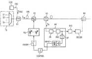
- FIG. 1shows an arrangement for determining a line discontinuity in accordance with the method according to the invention
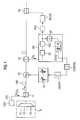
- FIG. 2shows an arrangement for measuring the transmission attenuation in accordance with the method according to the invention
- FIG. 1there is an illustration of an arrangement for determining a line discontinuity in accordance with the method according to the invention for detecting a check-back signal.
- Optical signals S 1 , S 2 , . . . , Snare fed from a transmitting unit Tx into an optical waveguide LWL in a transmission system, said signals are intended, for example, as wavelength or polarization multiplex signals.
- a first coupler K 1is arranged in the first section of the optical waveguide LWL.
- An encoding module CODis connected in series to the coupler K 1 , said encoding module encodes a check-back signal S OSC from a monitoring channel OSC of the transmission system in such a way that defined proportion of its output is concentrated in a narrow-band spectral range.
- the encoding modulehas a scrambler with subsequent CMI or RZ encoding.
- the clock frequency of the check-back signalis selected as the centre of the spectral range.
- a second coupler K 2for feeding in at least one pump signal from a pump source PQ and a third subsequent decoupler K 3 for bifurcating the check-back signal S OSC from the optical waveguide LWL.
- the decoupled check-back signal S OSCis delivered to a measuring device ME.
- the measuring device MEhas an opto-electrical modulator OE with a subsequent amplifier AGC (automatic gain control), which are usually used for the network management in an interface with decoupling of a check-back signal of the monitoring channel.
- AGCautomatic gain control
- the elements OE and AGC used herehave here the bandwidth of the check-back signal, so that the element AGC can also feed a regenerator REG with subsequent decoding module DECOD with descrambler.
- the check-back signal S OSCcan be supplied to the network management for evaluating and new data can be supplied onwards from the network management via a further encoding module COD with further scrambler and via an electrical-optical interface to the coupler K 4 .
- the opto-electric modulation and amplification of the decoupled check-back signal S OSCis linear and not amplitude limited so that the narrow-band spectral range of the decoupled check-back signal S OSC is not suppressed in its signal noise by amplitude limiting.
- the amplifier AGChas, moreover, a subsequent narrow-band band-pass filter BP, the relative bandwidth of which is about 5 to 10.10 ⁇ 5 of the total bandwidth from, for example, 2-3 MHz, of the check-back signal S OSC .
- a line discontinuityis inevitably detected.
- a threshold detector CONTROLinserted with a preset threshold, with series connected amplifier and rectifier as measuring module MEAS for determining an output level P, controls the switching on and off of the pump source PQ by means of a switch ON/OFF. When the transmission system is put into operation, all pump sources are switched off and are only switched on if the spectral line is present in the measuring module MEAS.
- FIG. 2shows an arrangement for measuring the transmission attenuation in accordance with the method according to the invention for detecting a check-back signal.
- FIG. 2has the features for the detection of a check-back signal as per FIG. 1 except for the components K 2 , PQ, ON/OFF, CONTROL.
- Signals RS 1 , RS 2 from the measuring module MEAS and from the gain controller AGCare transmitted to an evaluation unit PROC for measuring the transmission attenuation using the value determined for the output level P and for the set gain on the gain controller AGC.
- the output value Pis determined analogously.
- the evaluation unitsets up the ratio between the output determined at the exit of the decoupler K 3 and the output of the check-back signal S OSC fed in at the sending end using the coupler K 1 .
Landscapes
- Physics & Mathematics (AREA)
- Electromagnetism (AREA)
- Engineering & Computer Science (AREA)
- Computer Networks & Wireless Communication (AREA)
- Signal Processing (AREA)
- Optical Communication System (AREA)
- Lasers (AREA)
Abstract
Description
- a constant proportion of the output in a defined frequency range of the check-back signal is concentrated in as narrow-band spectral range as possible,
- at the sending end, the check-back signal is fed into the transmission system,
- after a section of the transmission system, the check-back signal is decoupled,
- the decoupled check-back signal is opto-electrically modulated, amplified and filtered to isolate the most narrow-band spectral line possible of the check-back signal,
- the output of the isolated narrow-band spectral line is determined for the detection of the check-back signal.
Claims (18)
Applications Claiming Priority (4)
| Application Number | Priority Date | Filing Date | Title |
|---|---|---|---|
| DE10216279ADE10216279A1 (en) | 2002-04-12 | 2002-04-12 | Method for the detection of a control signal in an optical transmission system |
| DE10216279.4 | 2002-04-12 | ||
| DE10216279 | 2002-04-12 | ||
| PCT/DE2003/001075WO2003088528A1 (en) | 2002-04-12 | 2003-04-01 | Method for detecting a check-back signal in an optical transmission system |
Publications (2)
| Publication Number | Publication Date |
|---|---|
| US20070269208A1 US20070269208A1 (en) | 2007-11-22 |
| US7920787B2true US7920787B2 (en) | 2011-04-05 |
Family
ID=28684986
Family Applications (1)
| Application Number | Title | Priority Date | Filing Date |
|---|---|---|---|
| US10/510,973Expired - Fee RelatedUS7920787B2 (en) | 2002-04-12 | 2003-04-01 | Method for detecting a check-back signal in an optical transmission system |
Country Status (7)
| Country | Link |
|---|---|
| US (1) | US7920787B2 (en) |
| EP (1) | EP1495559B1 (en) |
| CN (1) | CN100539473C (en) |
| AU (1) | AU2003229506B2 (en) |
| DE (2) | DE10216279A1 (en) |
| ES (1) | ES2253669T3 (en) |
| WO (1) | WO2003088528A1 (en) |
Cited By (60)
| Publication number | Priority date | Publication date | Assignee | Title |
|---|---|---|---|---|
| US20090190928A1 (en)* | 2006-06-13 | 2009-07-30 | Nokia Siemens Networks Gmbh & Co. | Method and arrangement for switching a raman pump laser on and/or off |
| US9244281B1 (en) | 2013-09-26 | 2016-01-26 | Rockwell Collins, Inc. | Display system and method using a detached combiner |
| US9244280B1 (en) | 2014-03-25 | 2016-01-26 | Rockwell Collins, Inc. | Near eye display system and method for display enhancement or redundancy |
| US9274339B1 (en) | 2010-02-04 | 2016-03-01 | Rockwell Collins, Inc. | Worn display system and method without requiring real time tracking for boresight precision |
| US9341846B2 (en) | 2012-04-25 | 2016-05-17 | Rockwell Collins Inc. | Holographic wide angle display |
| US9366864B1 (en) | 2011-09-30 | 2016-06-14 | Rockwell Collins, Inc. | System for and method of displaying information without need for a combiner alignment detector |
| US9507150B1 (en) | 2011-09-30 | 2016-11-29 | Rockwell Collins, Inc. | Head up display (HUD) using a bent waveguide assembly |
| US9519089B1 (en) | 2014-01-30 | 2016-12-13 | Rockwell Collins, Inc. | High performance volume phase gratings |
| US9523852B1 (en) | 2012-03-28 | 2016-12-20 | Rockwell Collins, Inc. | Micro collimator system and method for a head up display (HUD) |
| US9674413B1 (en) | 2013-04-17 | 2017-06-06 | Rockwell Collins, Inc. | Vision system and method having improved performance and solar mitigation |
| US9715110B1 (en) | 2014-09-25 | 2017-07-25 | Rockwell Collins, Inc. | Automotive head up display (HUD) |
| US9715067B1 (en) | 2011-09-30 | 2017-07-25 | Rockwell Collins, Inc. | Ultra-compact HUD utilizing waveguide pupil expander with surface relief gratings in high refractive index materials |
| US9933684B2 (en) | 2012-11-16 | 2018-04-03 | Rockwell Collins, Inc. | Transparent waveguide display providing upper and lower fields of view having a specific light output aperture configuration |
| US10088675B1 (en) | 2015-05-18 | 2018-10-02 | Rockwell Collins, Inc. | Turning light pipe for a pupil expansion system and method |
| US10108010B2 (en) | 2015-06-29 | 2018-10-23 | Rockwell Collins, Inc. | System for and method of integrating head up displays and head down displays |
| US10126552B2 (en) | 2015-05-18 | 2018-11-13 | Rockwell Collins, Inc. | Micro collimator system and method for a head up display (HUD) |
| US10156681B2 (en) | 2015-02-12 | 2018-12-18 | Digilens Inc. | Waveguide grating device |
| US10241330B2 (en) | 2014-09-19 | 2019-03-26 | Digilens, Inc. | Method and apparatus for generating input images for holographic waveguide displays |
| US10247943B1 (en) | 2015-05-18 | 2019-04-02 | Rockwell Collins, Inc. | Head up display (HUD) using a light pipe |
| US10295824B2 (en) | 2017-01-26 | 2019-05-21 | Rockwell Collins, Inc. | Head up display with an angled light pipe |
| US10359736B2 (en) | 2014-08-08 | 2019-07-23 | Digilens Inc. | Method for holographic mastering and replication |
| US10509241B1 (en) | 2009-09-30 | 2019-12-17 | Rockwell Collins, Inc. | Optical displays |
| US10545346B2 (en) | 2017-01-05 | 2020-01-28 | Digilens Inc. | Wearable heads up displays |
| US10598932B1 (en) | 2016-01-06 | 2020-03-24 | Rockwell Collins, Inc. | Head up display for integrating views of conformally mapped symbols and a fixed image source |
| US10642058B2 (en) | 2011-08-24 | 2020-05-05 | Digilens Inc. | Wearable data display |
| US10670876B2 (en) | 2011-08-24 | 2020-06-02 | Digilens Inc. | Waveguide laser illuminator incorporating a despeckler |
| US10678053B2 (en) | 2009-04-27 | 2020-06-09 | Digilens Inc. | Diffractive projection apparatus |
| US10690916B2 (en) | 2015-10-05 | 2020-06-23 | Digilens Inc. | Apparatus for providing waveguide displays with two-dimensional pupil expansion |
| US10725312B2 (en) | 2007-07-26 | 2020-07-28 | Digilens Inc. | Laser illumination device |
| US10732569B2 (en) | 2018-01-08 | 2020-08-04 | Digilens Inc. | Systems and methods for high-throughput recording of holographic gratings in waveguide cells |
| US10732407B1 (en) | 2014-01-10 | 2020-08-04 | Rockwell Collins, Inc. | Near eye head up display system and method with fixed combiner |
| US10747982B2 (en) | 2013-07-31 | 2020-08-18 | Digilens Inc. | Method and apparatus for contact image sensing |
| US10795160B1 (en) | 2014-09-25 | 2020-10-06 | Rockwell Collins, Inc. | Systems for and methods of using fold gratings for dual axis expansion |
| US10859768B2 (en) | 2016-03-24 | 2020-12-08 | Digilens Inc. | Method and apparatus for providing a polarization selective holographic waveguide device |
| US10890707B2 (en) | 2016-04-11 | 2021-01-12 | Digilens Inc. | Holographic waveguide apparatus for structured light projection |
| US10914950B2 (en) | 2018-01-08 | 2021-02-09 | Digilens Inc. | Waveguide architectures and related methods of manufacturing |
| US10942430B2 (en) | 2017-10-16 | 2021-03-09 | Digilens Inc. | Systems and methods for multiplying the image resolution of a pixelated display |
| US11256155B2 (en) | 2012-01-06 | 2022-02-22 | Digilens Inc. | Contact image sensor using switchable Bragg gratings |
| US11300795B1 (en) | 2009-09-30 | 2022-04-12 | Digilens Inc. | Systems for and methods of using fold gratings coordinated with output couplers for dual axis expansion |
| US11307432B2 (en) | 2014-08-08 | 2022-04-19 | Digilens Inc. | Waveguide laser illuminator incorporating a Despeckler |
| US11314084B1 (en) | 2011-09-30 | 2022-04-26 | Rockwell Collins, Inc. | Waveguide combiner system and method with less susceptibility to glare |
| US11320571B2 (en) | 2012-11-16 | 2022-05-03 | Rockwell Collins, Inc. | Transparent waveguide display providing upper and lower fields of view with uniform light extraction |
| US11366316B2 (en) | 2015-05-18 | 2022-06-21 | Rockwell Collins, Inc. | Head up display (HUD) using a light pipe |
| US11378732B2 (en) | 2019-03-12 | 2022-07-05 | DigLens Inc. | Holographic waveguide backlight and related methods of manufacturing |
| US11402801B2 (en) | 2018-07-25 | 2022-08-02 | Digilens Inc. | Systems and methods for fabricating a multilayer optical structure |
| US11442222B2 (en) | 2019-08-29 | 2022-09-13 | Digilens Inc. | Evacuated gratings and methods of manufacturing |
| US11487131B2 (en) | 2011-04-07 | 2022-11-01 | Digilens Inc. | Laser despeckler based on angular diversity |
| US11513350B2 (en) | 2016-12-02 | 2022-11-29 | Digilens Inc. | Waveguide device with uniform output illumination |
| US11543594B2 (en) | 2019-02-15 | 2023-01-03 | Digilens Inc. | Methods and apparatuses for providing a holographic waveguide display using integrated gratings |
| US11681143B2 (en) | 2019-07-29 | 2023-06-20 | Digilens Inc. | Methods and apparatus for multiplying the image resolution and field-of-view of a pixelated display |
| US11726332B2 (en) | 2009-04-27 | 2023-08-15 | Digilens Inc. | Diffractive projection apparatus |
| US11726329B2 (en) | 2015-01-12 | 2023-08-15 | Digilens Inc. | Environmentally isolated waveguide display |
| US11747568B2 (en) | 2019-06-07 | 2023-09-05 | Digilens Inc. | Waveguides incorporating transmissive and reflective gratings and related methods of manufacturing |
| US12092914B2 (en) | 2018-01-08 | 2024-09-17 | Digilens Inc. | Systems and methods for manufacturing waveguide cells |
| US12140764B2 (en) | 2019-02-15 | 2024-11-12 | Digilens Inc. | Wide angle waveguide display |
| US12158612B2 (en) | 2021-03-05 | 2024-12-03 | Digilens Inc. | Evacuated periodic structures and methods of manufacturing |
| US12210153B2 (en) | 2019-01-14 | 2025-01-28 | Digilens Inc. | Holographic waveguide display with light control layer |
| US12306585B2 (en) | 2018-01-08 | 2025-05-20 | Digilens Inc. | Methods for fabricating optical waveguides |
| US12397477B2 (en) | 2019-02-05 | 2025-08-26 | Digilens Inc. | Methods for compensating for optical surface nonuniformity |
| US12399326B2 (en) | 2021-01-07 | 2025-08-26 | Digilens Inc. | Grating structures for color waveguides |
Citations (8)
| Publication number | Priority date | Publication date | Assignee | Title |
|---|---|---|---|---|
| US6285475B1 (en)* | 1995-12-29 | 2001-09-04 | Mci Communications Corporation | Method and system for detecting optical faults in a network fiber link |
| US20010033406A1 (en) | 2000-02-03 | 2001-10-25 | Yasuhiro Koike | Optical transmitter-receiver |
| DE10024238A1 (en) | 2000-05-12 | 2002-01-03 | Hertz Inst Heinrich | Process for quality and identity control of wavelength channels in optical transmission networks |
| DE10046104A1 (en) | 2000-09-18 | 2002-04-04 | Siemens Ag | Line breakage detection method for optical WDM-system verifies presence of pilot tone modulated on transmitted optical signal |
| US20020048062A1 (en)* | 2000-08-08 | 2002-04-25 | Takeshi Sakamoto | Wavelength division multiplexing optical communication system and wavelength division multiplexing optical communication method |
| US20030072064A1 (en)* | 2001-10-12 | 2003-04-17 | Fujitsu Limited | Supervisory controlling method and supervisory controlling system of optical repeater |
| US6650840B2 (en)* | 1998-03-27 | 2003-11-18 | Lucent Technologies Inc. | Method for identifying faults in a branched optical network |
| US7792425B2 (en)* | 2004-04-14 | 2010-09-07 | Finisar Corporation | Network data transmission and diagnostic methods using out-of-band data |
- 2002
- 2002-04-12DEDE10216279Apatent/DE10216279A1/ennot_activeWithdrawn
- 2003
- 2003-04-01EPEP03722250Apatent/EP1495559B1/ennot_activeExpired - Lifetime
- 2003-04-01USUS10/510,973patent/US7920787B2/ennot_activeExpired - Fee Related
- 2003-04-01AUAU2003229506Apatent/AU2003229506B2/ennot_activeCeased
- 2003-04-01ESES03722250Tpatent/ES2253669T3/ennot_activeExpired - Lifetime
- 2003-04-01WOPCT/DE2003/001075patent/WO2003088528A1/enactiveIP Right Grant
- 2003-04-01CNCNB038135272Apatent/CN100539473C/ennot_activeExpired - Lifetime
- 2003-04-01DEDE50302428Tpatent/DE50302428D1/ennot_activeExpired - Lifetime
Patent Citations (8)
| Publication number | Priority date | Publication date | Assignee | Title |
|---|---|---|---|---|
| US6285475B1 (en)* | 1995-12-29 | 2001-09-04 | Mci Communications Corporation | Method and system for detecting optical faults in a network fiber link |
| US6650840B2 (en)* | 1998-03-27 | 2003-11-18 | Lucent Technologies Inc. | Method for identifying faults in a branched optical network |
| US20010033406A1 (en) | 2000-02-03 | 2001-10-25 | Yasuhiro Koike | Optical transmitter-receiver |
| DE10024238A1 (en) | 2000-05-12 | 2002-01-03 | Hertz Inst Heinrich | Process for quality and identity control of wavelength channels in optical transmission networks |
| US20020048062A1 (en)* | 2000-08-08 | 2002-04-25 | Takeshi Sakamoto | Wavelength division multiplexing optical communication system and wavelength division multiplexing optical communication method |
| DE10046104A1 (en) | 2000-09-18 | 2002-04-04 | Siemens Ag | Line breakage detection method for optical WDM-system verifies presence of pilot tone modulated on transmitted optical signal |
| US20030072064A1 (en)* | 2001-10-12 | 2003-04-17 | Fujitsu Limited | Supervisory controlling method and supervisory controlling system of optical repeater |
| US7792425B2 (en)* | 2004-04-14 | 2010-09-07 | Finisar Corporation | Network data transmission and diagnostic methods using out-of-band data |
Non-Patent Citations (1)
| Title |
|---|
| Giammarco Rossi, Timothy E. Dimmick and Daniel J. Blumenthal, "Optical Performance Monitoring in Reconfigurable WDM Optical Networks Using Subcarrier Multiplexing", Journal of Lightwave Technology, IEEE, New York, US, vol. 18, No. 12, Dec. 2000, pp. 1639-1648, XP002179167. |
Cited By (100)
| Publication number | Priority date | Publication date | Assignee | Title |
|---|---|---|---|---|
| US8301031B2 (en)* | 2006-06-13 | 2012-10-30 | Nokia Siemens Networks Gmbh & Co. Kg | Method and arrangement for switching a Raman pump laser on and/or off |
| US20090190928A1 (en)* | 2006-06-13 | 2009-07-30 | Nokia Siemens Networks Gmbh & Co. | Method and arrangement for switching a raman pump laser on and/or off |
| US10725312B2 (en) | 2007-07-26 | 2020-07-28 | Digilens Inc. | Laser illumination device |
| US11175512B2 (en) | 2009-04-27 | 2021-11-16 | Digilens Inc. | Diffractive projection apparatus |
| US10678053B2 (en) | 2009-04-27 | 2020-06-09 | Digilens Inc. | Diffractive projection apparatus |
| US11726332B2 (en) | 2009-04-27 | 2023-08-15 | Digilens Inc. | Diffractive projection apparatus |
| US11300795B1 (en) | 2009-09-30 | 2022-04-12 | Digilens Inc. | Systems for and methods of using fold gratings coordinated with output couplers for dual axis expansion |
| US10509241B1 (en) | 2009-09-30 | 2019-12-17 | Rockwell Collins, Inc. | Optical displays |
| US9274339B1 (en) | 2010-02-04 | 2016-03-01 | Rockwell Collins, Inc. | Worn display system and method without requiring real time tracking for boresight precision |
| US11487131B2 (en) | 2011-04-07 | 2022-11-01 | Digilens Inc. | Laser despeckler based on angular diversity |
| US11287666B2 (en) | 2011-08-24 | 2022-03-29 | Digilens, Inc. | Wearable data display |
| US12306418B2 (en) | 2011-08-24 | 2025-05-20 | Rockwell Collins, Inc. | Wearable data display |
| US10670876B2 (en) | 2011-08-24 | 2020-06-02 | Digilens Inc. | Waveguide laser illuminator incorporating a despeckler |
| US10642058B2 (en) | 2011-08-24 | 2020-05-05 | Digilens Inc. | Wearable data display |
| US9366864B1 (en) | 2011-09-30 | 2016-06-14 | Rockwell Collins, Inc. | System for and method of displaying information without need for a combiner alignment detector |
| US10401620B1 (en) | 2011-09-30 | 2019-09-03 | Rockwell Collins, Inc. | Waveguide combiner system and method with less susceptibility to glare |
| US9599813B1 (en) | 2011-09-30 | 2017-03-21 | Rockwell Collins, Inc. | Waveguide combiner system and method with less susceptibility to glare |
| US9715067B1 (en) | 2011-09-30 | 2017-07-25 | Rockwell Collins, Inc. | Ultra-compact HUD utilizing waveguide pupil expander with surface relief gratings in high refractive index materials |
| US11314084B1 (en) | 2011-09-30 | 2022-04-26 | Rockwell Collins, Inc. | Waveguide combiner system and method with less susceptibility to glare |
| US9977247B1 (en) | 2011-09-30 | 2018-05-22 | Rockwell Collins, Inc. | System for and method of displaying information without need for a combiner alignment detector |
| US9507150B1 (en) | 2011-09-30 | 2016-11-29 | Rockwell Collins, Inc. | Head up display (HUD) using a bent waveguide assembly |
| US11256155B2 (en) | 2012-01-06 | 2022-02-22 | Digilens Inc. | Contact image sensor using switchable Bragg gratings |
| US9523852B1 (en) | 2012-03-28 | 2016-12-20 | Rockwell Collins, Inc. | Micro collimator system and method for a head up display (HUD) |
| US11460621B2 (en) | 2012-04-25 | 2022-10-04 | Rockwell Collins, Inc. | Holographic wide angle display |
| US10690915B2 (en) | 2012-04-25 | 2020-06-23 | Rockwell Collins, Inc. | Holographic wide angle display |
| US9341846B2 (en) | 2012-04-25 | 2016-05-17 | Rockwell Collins Inc. | Holographic wide angle display |
| US12276895B2 (en) | 2012-11-16 | 2025-04-15 | Rockwell Collins, Inc. | Transparent waveguide display with passive expander input bragg gratings with different angular diffraction efficiencies |
| US9933684B2 (en) | 2012-11-16 | 2018-04-03 | Rockwell Collins, Inc. | Transparent waveguide display providing upper and lower fields of view having a specific light output aperture configuration |
| US11320571B2 (en) | 2012-11-16 | 2022-05-03 | Rockwell Collins, Inc. | Transparent waveguide display providing upper and lower fields of view with uniform light extraction |
| US11815781B2 (en) | 2012-11-16 | 2023-11-14 | Rockwell Collins, Inc. | Transparent waveguide display |
| US20180373115A1 (en)* | 2012-11-16 | 2018-12-27 | Digilens, Inc. | Transparent Waveguide Display |
| US11448937B2 (en) | 2012-11-16 | 2022-09-20 | Digilens Inc. | Transparent waveguide display for tiling a display having plural optical powers using overlapping and offset FOV tiles |
| US12405507B2 (en) | 2012-11-16 | 2025-09-02 | Digilens Inc. | Transparent waveguide display with grating lamina that both couple and extract modulated light |
| US9674413B1 (en) | 2013-04-17 | 2017-06-06 | Rockwell Collins, Inc. | Vision system and method having improved performance and solar mitigation |
| US9679367B1 (en) | 2013-04-17 | 2017-06-13 | Rockwell Collins, Inc. | HUD system and method with dynamic light exclusion |
| US10747982B2 (en) | 2013-07-31 | 2020-08-18 | Digilens Inc. | Method and apparatus for contact image sensing |
| US9244281B1 (en) | 2013-09-26 | 2016-01-26 | Rockwell Collins, Inc. | Display system and method using a detached combiner |
| US10732407B1 (en) | 2014-01-10 | 2020-08-04 | Rockwell Collins, Inc. | Near eye head up display system and method with fixed combiner |
| US9519089B1 (en) | 2014-01-30 | 2016-12-13 | Rockwell Collins, Inc. | High performance volume phase gratings |
| US9766465B1 (en) | 2014-03-25 | 2017-09-19 | Rockwell Collins, Inc. | Near eye display system and method for display enhancement or redundancy |
| US9244280B1 (en) | 2014-03-25 | 2016-01-26 | Rockwell Collins, Inc. | Near eye display system and method for display enhancement or redundancy |
| US11709373B2 (en) | 2014-08-08 | 2023-07-25 | Digilens Inc. | Waveguide laser illuminator incorporating a despeckler |
| US10359736B2 (en) | 2014-08-08 | 2019-07-23 | Digilens Inc. | Method for holographic mastering and replication |
| US11307432B2 (en) | 2014-08-08 | 2022-04-19 | Digilens Inc. | Waveguide laser illuminator incorporating a Despeckler |
| US11726323B2 (en) | 2014-09-19 | 2023-08-15 | Digilens Inc. | Method and apparatus for generating input images for holographic waveguide displays |
| US10241330B2 (en) | 2014-09-19 | 2019-03-26 | Digilens, Inc. | Method and apparatus for generating input images for holographic waveguide displays |
| US9715110B1 (en) | 2014-09-25 | 2017-07-25 | Rockwell Collins, Inc. | Automotive head up display (HUD) |
| US11579455B2 (en) | 2014-09-25 | 2023-02-14 | Rockwell Collins, Inc. | Systems for and methods of using fold gratings for dual axis expansion using polarized light for wave plates on waveguide faces |
| US10795160B1 (en) | 2014-09-25 | 2020-10-06 | Rockwell Collins, Inc. | Systems for and methods of using fold gratings for dual axis expansion |
| US11740472B2 (en) | 2015-01-12 | 2023-08-29 | Digilens Inc. | Environmentally isolated waveguide display |
| US11726329B2 (en) | 2015-01-12 | 2023-08-15 | Digilens Inc. | Environmentally isolated waveguide display |
| US12379547B2 (en) | 2015-02-12 | 2025-08-05 | Digilens Inc. | Waveguide grating device |
| US10156681B2 (en) | 2015-02-12 | 2018-12-18 | Digilens Inc. | Waveguide grating device |
| US10527797B2 (en) | 2015-02-12 | 2020-01-07 | Digilens Inc. | Waveguide grating device |
| US11703645B2 (en) | 2015-02-12 | 2023-07-18 | Digilens Inc. | Waveguide grating device |
| US10247943B1 (en) | 2015-05-18 | 2019-04-02 | Rockwell Collins, Inc. | Head up display (HUD) using a light pipe |
| US10698203B1 (en) | 2015-05-18 | 2020-06-30 | Rockwell Collins, Inc. | Turning light pipe for a pupil expansion system and method |
| US11366316B2 (en) | 2015-05-18 | 2022-06-21 | Rockwell Collins, Inc. | Head up display (HUD) using a light pipe |
| US10088675B1 (en) | 2015-05-18 | 2018-10-02 | Rockwell Collins, Inc. | Turning light pipe for a pupil expansion system and method |
| US10126552B2 (en) | 2015-05-18 | 2018-11-13 | Rockwell Collins, Inc. | Micro collimator system and method for a head up display (HUD) |
| US10746989B2 (en) | 2015-05-18 | 2020-08-18 | Rockwell Collins, Inc. | Micro collimator system and method for a head up display (HUD) |
| US10108010B2 (en) | 2015-06-29 | 2018-10-23 | Rockwell Collins, Inc. | System for and method of integrating head up displays and head down displays |
| US10690916B2 (en) | 2015-10-05 | 2020-06-23 | Digilens Inc. | Apparatus for providing waveguide displays with two-dimensional pupil expansion |
| US12405471B2 (en) | 2015-10-05 | 2025-09-02 | Digilens Inc. | Apparatus for providing waveguide displays with two-dimensional pupil expansion |
| US11754842B2 (en) | 2015-10-05 | 2023-09-12 | Digilens Inc. | Apparatus for providing waveguide displays with two-dimensional pupil expansion |
| US11281013B2 (en) | 2015-10-05 | 2022-03-22 | Digilens Inc. | Apparatus for providing waveguide displays with two-dimensional pupil expansion |
| US11215834B1 (en) | 2016-01-06 | 2022-01-04 | Rockwell Collins, Inc. | Head up display for integrating views of conformally mapped symbols and a fixed image source |
| US10598932B1 (en) | 2016-01-06 | 2020-03-24 | Rockwell Collins, Inc. | Head up display for integrating views of conformally mapped symbols and a fixed image source |
| US11604314B2 (en) | 2016-03-24 | 2023-03-14 | Digilens Inc. | Method and apparatus for providing a polarization selective holographic waveguide device |
| US10859768B2 (en) | 2016-03-24 | 2020-12-08 | Digilens Inc. | Method and apparatus for providing a polarization selective holographic waveguide device |
| US10890707B2 (en) | 2016-04-11 | 2021-01-12 | Digilens Inc. | Holographic waveguide apparatus for structured light projection |
| US11513350B2 (en) | 2016-12-02 | 2022-11-29 | Digilens Inc. | Waveguide device with uniform output illumination |
| US12298513B2 (en) | 2016-12-02 | 2025-05-13 | Digilens Inc. | Waveguide device with uniform output illumination |
| US11586046B2 (en) | 2017-01-05 | 2023-02-21 | Digilens Inc. | Wearable heads up displays |
| US12248150B2 (en) | 2017-01-05 | 2025-03-11 | Digilens Inc. | Wearable heads up displays |
| US10545346B2 (en) | 2017-01-05 | 2020-01-28 | Digilens Inc. | Wearable heads up displays |
| US11194162B2 (en) | 2017-01-05 | 2021-12-07 | Digilens Inc. | Wearable heads up displays |
| US10295824B2 (en) | 2017-01-26 | 2019-05-21 | Rockwell Collins, Inc. | Head up display with an angled light pipe |
| US10705337B2 (en) | 2017-01-26 | 2020-07-07 | Rockwell Collins, Inc. | Head up display with an angled light pipe |
| US10942430B2 (en) | 2017-10-16 | 2021-03-09 | Digilens Inc. | Systems and methods for multiplying the image resolution of a pixelated display |
| US12352960B2 (en) | 2018-01-08 | 2025-07-08 | Digilens Inc. | Waveguide architectures and related methods of manufacturing |
| US12306585B2 (en) | 2018-01-08 | 2025-05-20 | Digilens Inc. | Methods for fabricating optical waveguides |
| US12092914B2 (en) | 2018-01-08 | 2024-09-17 | Digilens Inc. | Systems and methods for manufacturing waveguide cells |
| US12366823B2 (en) | 2018-01-08 | 2025-07-22 | Digilens Inc. | Systems and methods for high-throughput recording of holographic gratings in waveguide cells |
| US10914950B2 (en) | 2018-01-08 | 2021-02-09 | Digilens Inc. | Waveguide architectures and related methods of manufacturing |
| US10732569B2 (en) | 2018-01-08 | 2020-08-04 | Digilens Inc. | Systems and methods for high-throughput recording of holographic gratings in waveguide cells |
| US11402801B2 (en) | 2018-07-25 | 2022-08-02 | Digilens Inc. | Systems and methods for fabricating a multilayer optical structure |
| US12210153B2 (en) | 2019-01-14 | 2025-01-28 | Digilens Inc. | Holographic waveguide display with light control layer |
| US12397477B2 (en) | 2019-02-05 | 2025-08-26 | Digilens Inc. | Methods for compensating for optical surface nonuniformity |
| US12140764B2 (en) | 2019-02-15 | 2024-11-12 | Digilens Inc. | Wide angle waveguide display |
| US11543594B2 (en) | 2019-02-15 | 2023-01-03 | Digilens Inc. | Methods and apparatuses for providing a holographic waveguide display using integrated gratings |
| US11378732B2 (en) | 2019-03-12 | 2022-07-05 | DigLens Inc. | Holographic waveguide backlight and related methods of manufacturing |
| US11747568B2 (en) | 2019-06-07 | 2023-09-05 | Digilens Inc. | Waveguides incorporating transmissive and reflective gratings and related methods of manufacturing |
| US12271035B2 (en) | 2019-06-07 | 2025-04-08 | Digilens Inc. | Waveguides incorporating transmissive and reflective gratings and related methods of manufacturing |
| US11681143B2 (en) | 2019-07-29 | 2023-06-20 | Digilens Inc. | Methods and apparatus for multiplying the image resolution and field-of-view of a pixelated display |
| US11442222B2 (en) | 2019-08-29 | 2022-09-13 | Digilens Inc. | Evacuated gratings and methods of manufacturing |
| US11592614B2 (en) | 2019-08-29 | 2023-02-28 | Digilens Inc. | Evacuated gratings and methods of manufacturing |
| US11899238B2 (en) | 2019-08-29 | 2024-02-13 | Digilens Inc. | Evacuated gratings and methods of manufacturing |
| US12399326B2 (en) | 2021-01-07 | 2025-08-26 | Digilens Inc. | Grating structures for color waveguides |
| US12158612B2 (en) | 2021-03-05 | 2024-12-03 | Digilens Inc. | Evacuated periodic structures and methods of manufacturing |
Also Published As
| Publication number | Publication date |
|---|---|
| EP1495559B1 (en) | 2006-02-15 |
| AU2003229506B2 (en) | 2007-06-14 |
| WO2003088528A1 (en) | 2003-10-23 |
| EP1495559A1 (en) | 2005-01-12 |
| DE50302428D1 (en) | 2006-04-20 |
| ES2253669T3 (en) | 2006-06-01 |
| DE10216279A1 (en) | 2003-10-30 |
| US20070269208A1 (en) | 2007-11-22 |
| CN1659807A (en) | 2005-08-24 |
| AU2003229506A1 (en) | 2003-10-27 |
| CN100539473C (en) | 2009-09-09 |
Similar Documents
| Publication | Publication Date | Title |
|---|---|---|
| US7920787B2 (en) | Method for detecting a check-back signal in an optical transmission system | |
| US10560185B2 (en) | Optical line card with optical signal power monitor | |
| US6891659B2 (en) | Optical amplifiers, optical fiber raman amplifiers and optical systems | |
| US6452701B1 (en) | Wavelength division multiplexing communications network supervisory system | |
| EP2271005B1 (en) | Optical bidirectional communication system with supervisory channel | |
| US7092630B2 (en) | Open fiber control for optical transceivers | |
| US5436750A (en) | Optical repeatered transmission with fault locating capability | |
| JP2004531948A (en) | Optical transmission system with monitoring system | |
| EP1892859A1 (en) | A method for realizing the laser safety protection, an optical amplifier and a methode for adding an identifier signal | |
| US7957643B2 (en) | Method and apparatus for automatically controlling optical signal power in optical transmission systems | |
| JP4492227B2 (en) | Optical transmission system, pumping light source stopping device and pumping light source stopping method used in the system | |
| EP1610475B1 (en) | Optical transmission path failure detection system | |
| US7130537B1 (en) | Safety shutdown system for a WDM fiber optic communications network | |
| US6806998B2 (en) | Raman amplifier with high power distribution bypass | |
| JP4615155B2 (en) | Optical communication method and system | |
| JP2007043521A (en) | Optical transceiver and wavelength division multiplexing communication system | |
| KR20010005209A (en) | Apparatus for detecting los of optical pre-amplifier uint in transmission system |
Legal Events
| Date | Code | Title | Description |
|---|---|---|---|
| AS | Assignment | Owner name:SIEMENS AKTIENGESELLSCHAFT, GERMANY Free format text:ASSIGNMENT OF ASSIGNORS INTEREST;ASSIGNORS:GENTNER, GUIDO;NEUMANN, RENE;THANHAUSER, GERHARD;REEL/FRAME:016351/0055 Effective date:20040930 | |
| AS | Assignment | Owner name:NOKIA SIEMENS NETWORKS GMBH & CO. KG, GERMANY Free format text:ASSIGNMENT OF ASSIGNORS INTEREST;ASSIGNOR:SIEMENS AKTIENGESELLSCHAFT;REEL/FRAME:020828/0926 Effective date:20080327 | |
| FEPP | Fee payment procedure | Free format text:PAYOR NUMBER ASSIGNED (ORIGINAL EVENT CODE: ASPN); ENTITY STATUS OF PATENT OWNER: LARGE ENTITY | |
| STCF | Information on status: patent grant | Free format text:PATENTED CASE | |
| AS | Assignment | Owner name:XIEON NETWORKS S.A.R.L., LUXEMBOURG Free format text:ASSIGNMENT OF ASSIGNORS INTEREST;ASSIGNOR:NOKIA SIEMENS NETWORKS GMBH & CO. KG;REEL/FRAME:031719/0220 Effective date:20130706 | |
| FPAY | Fee payment | Year of fee payment:4 | |
| AS | Assignment | Owner name:CERBERUS BUSINESS FINANCE, LLC, AS COLLATERAL AGEN Free format text:SECURITY INTEREST;ASSIGNOR:XIEON NETWORKS S.A R.L;REEL/FRAME:034639/0201 Effective date:20141208 | |
| MAFP | Maintenance fee payment | Free format text:PAYMENT OF MAINTENANCE FEE, 8TH YEAR, LARGE ENTITY (ORIGINAL EVENT CODE: M1552); ENTITY STATUS OF PATENT OWNER: LARGE ENTITY Year of fee payment:8 | |
| AS | Assignment | Owner name:XIEON NETWORKS S.A.R.L., ILLINOIS Free format text:RELEASE BY SECURED PARTY;ASSIGNOR:CERBERUS BUSINESS FINANCE, LLC;REEL/FRAME:047335/0952 Effective date:20181001 | |
| FEPP | Fee payment procedure | Free format text:MAINTENANCE FEE REMINDER MAILED (ORIGINAL EVENT CODE: REM.); ENTITY STATUS OF PATENT OWNER: LARGE ENTITY | |
| LAPS | Lapse for failure to pay maintenance fees | Free format text:PATENT EXPIRED FOR FAILURE TO PAY MAINTENANCE FEES (ORIGINAL EVENT CODE: EXP.); ENTITY STATUS OF PATENT OWNER: LARGE ENTITY | |
| STCH | Information on status: patent discontinuation | Free format text:PATENT EXPIRED DUE TO NONPAYMENT OF MAINTENANCE FEES UNDER 37 CFR 1.362 | |
| FP | Lapsed due to failure to pay maintenance fee | Effective date:20230405 |