US7919928B2 - Boost LED driver not using output capacitor and blocking diode - Google Patents
Boost LED driver not using output capacitor and blocking diodeDownload PDFInfo
- Publication number
- US7919928B2 US7919928B2US12/115,471US11547108AUS7919928B2US 7919928 B2US7919928 B2US 7919928B2US 11547108 AUS11547108 AUS 11547108AUS 7919928 B2US7919928 B2US 7919928B2
- Authority
- US
- United States
- Prior art keywords
- leds
- voltage
- current
- switching transistor
- driver
- Prior art date
- Legal status (The legal status is an assumption and is not a legal conclusion. Google has not performed a legal analysis and makes no representation as to the accuracy of the status listed.)
- Expired - Fee Related, expires
Links
Images


Classifications
- H—ELECTRICITY
- H05—ELECTRIC TECHNIQUES NOT OTHERWISE PROVIDED FOR
- H05B—ELECTRIC HEATING; ELECTRIC LIGHT SOURCES NOT OTHERWISE PROVIDED FOR; CIRCUIT ARRANGEMENTS FOR ELECTRIC LIGHT SOURCES, IN GENERAL
- H05B45/00—Circuit arrangements for operating light-emitting diodes [LED]
- H05B45/30—Driver circuits
- H05B45/37—Converter circuits
- H05B45/3725—Switched mode power supply [SMPS]
- H05B45/38—Switched mode power supply [SMPS] using boost topology
- Y—GENERAL TAGGING OF NEW TECHNOLOGICAL DEVELOPMENTS; GENERAL TAGGING OF CROSS-SECTIONAL TECHNOLOGIES SPANNING OVER SEVERAL SECTIONS OF THE IPC; TECHNICAL SUBJECTS COVERED BY FORMER USPC CROSS-REFERENCE ART COLLECTIONS [XRACs] AND DIGESTS
- Y02—TECHNOLOGIES OR APPLICATIONS FOR MITIGATION OR ADAPTATION AGAINST CLIMATE CHANGE
- Y02B—CLIMATE CHANGE MITIGATION TECHNOLOGIES RELATED TO BUILDINGS, e.g. HOUSING, HOUSE APPLIANCES OR RELATED END-USER APPLICATIONS
- Y02B20/00—Energy efficient lighting technologies, e.g. halogen lamps or gas discharge lamps
- Y02B20/30—Semiconductor lamps, e.g. solid state lamps [SSL] light emitting diodes [LED] or organic LED [OLED]
Definitions
- This inventionrelates to light emitting diode (LED) drivers and, in particular, to LED drivers that boost an input voltage to drive LEDs connected in series.
- LEDlight emitting diode
- LEDsare rapidly replacing incandescent bulbs, fluorescent bulbs, and other types of light sources due to their efficiency, small size, high reliability, and selectable color emission.
- a typical forward voltage drop for a high power LEDis about 3-4 volts.
- the brightness of an LEDis controlled by the current through the LED, which ranges from a few milliamps to an amp or more, depending on the type of LED. For this reason, LED drivers typically include some means to control the LED current.
- boost convertersare typically used in LED drivers that convert a low input voltage into a much higher voltage (e.g., up to 100 volts) to drive a selectable number of LEDs in series.
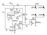
- FIG. 1is a typical prior art LED driver 10 that drives multiple LEDs 14 in series. Most components of the driver 10 are formed on an integrated circuit chip 12 . Since the same chip 12 is used in one embodiment of the present invention, the operation of the driver 10 will be described in detail.
- the driver 10is a DC boost regulator that up-converts an input voltage (Vin) to the required output voltage (Vout) needed to drive the series-connected LEDs 14 at a desired regulated current.
- the regulatorswitches a switching transistor Q 1 at a certain pulse-width modulation (PWM) duty cycle to maintain Vout at the required level.
- PWMpulse-width modulation
- the switchingis at a high frequency, such as 100 KHz-5 MHz, to keep component sizes small.
- transistor Q 1When transistor Q 1 is turned off, the polarity of the voltage at the anode of diode D 1 reverses, and diode D 1 turns on. The stored inductor energy is then discharged, as a ramping down current, to recharge the capacitor Cout, while a smooth current flows through the LEDs.
- the relatively large value of the capacitor Coutmaintains Vout at a relatively constant level (i.e., low ripple) to provide a smooth regulated current through the LEDs.
- the duty cycle needed to maintain Vout (and thus the current) at the required level to drive the LEDsis set as follows.
- a low value resistor R 1 in series with the LEDshas a voltage drop equal to I LED *R 1 .
- This voltage dropis a feedback voltage (Vfb) into the controller.
- An error amplifier 16(an op amp) receives Vfb and a reference voltage (Vref) and generates an error signal related to the difference between Vfb and Vref. Any difference between Vfb and Vref causes the error signal to correspondingly charge or discharge a compensation capacitor Ccomp, through a compensation resistor Rcomp.
- the resulting voltage (Vcontrol) at the output of the amplifier 16is relatively stable.
- the magnitude of Vcontrolis directly related to the duty cycle of the boost regulator, and the duty cycle is that required to cause Vfb to equal Vref (i.e., zero error signal).
- a low value resistor R 2is connected in series with the switching transistor Q 1 so that, when Q 1 is on and conducting a ramping current through the inductor L 1 , the R 2 voltage drop is a rising ramped voltage. This rising voltage is amplified, as required, by an amplifier 20 and applied to one input of a PWM comparator 22 . The comparator's 22 other input is Vcontrol.
- a clockis connected to the set input of an RS flip-flop 24 to set the Q output at the beginning of each clock cycle.
- the clockhas a typical frequency between 100 KHz and 5 MHz.
- the high output of the flip-flop 24 at the start of the cycleis amplified by an amplifier 25 , if necessary, to turn on the switching transistor Q 1 , shown as an N-channel MOSFET.
- the transistorcan be any suitable type.
- the output of the comparator 22is connected to the reset input of the flip-flop 24 . When the rising voltage crosses Vcontrol, the output of the comparator 22 goes high and causes the Q output of the flip-flop 24 to be reset to zero to turn off the transistor Q 1 .
- the duty cycle of the switching transistor Q 1is controlled to generate a smooth current through the LEDs required to cause Vfb to equal Vref.
- the value of resistor R 1can be selected to achieve any desired regulated current.
- boost regulatorsNumerous other types of boost regulators can also be used.
- the capacitor Coutmust have a high voltage rating, such as 100 v, to handle the boosted voltage and any voltage spikes. Additionally, the value of the capacitor Cout is typically in the range of 1-10 ⁇ F so that there is only a small Vout ripple. When driving LEDs, a small variation in the driving voltage may cause a large variation in the current through the LEDs, making the brightness hard to accurately control. Such high value HV capacitors require a relatively large amount of space and are expensive.
- the blocking diode D 1is typically external to the controller IC chip 12 and must be purchased separately by the user and connected to the controller. Such an external diode and its connection add cost and uses space.
- boost LED driverthat is smaller and less expensive than the typically LED driver, such as shown in FIG. 1 .
- An LED driverthat boosts an input voltage to drive any number of LEDs in series.
- a blocking diode and output capacitorare not used, so that the resulting driver may be made smaller and less expensively than prior art drivers.
- a boost regulatorswitches a transistor on and off at a high frequency duty cycle.
- the transistorconnects one end of an inductor to ground when the transistor is on, as with prior art boost converters, to energize the inductor for each cycle.
- the node of the switching transistor and inductoris directly connected to an anode of the “top” LED in the series string of LEDs.
- the switching transistorWhen the switching transistor is turned off, the charged inductor supplies current through the LEDs. There is no blocking diode or output capacitor, so the current through the LEDs is pulsed rather than constant.
- the cathode of the “bottom” LED in the stringis connected to ground via a low value sense resistor. In parallel with the sense resistor is connected a filter resistor and filter capacitor, forming an RC filter.
- the filter capacitorprovides a feedback voltage for the boost regulator.
- the filter capacitorsmoothes the pulsing voltage at the sense resistor generated by the pulsed current through the LEDs when the switching transistor is turned off. Therefore, the feedback voltage is relatively stable over the entire switching cycle.
- the filter resistoris a relatively high value resistor for preventing the filter capacitor from discharging through the sense resistor when the switching transistor is on and the LEDs are off.
- the filter capacitorSince the filter capacitor is connected to the bottom LED (the bottom LED only sees a low voltage) and the value of the sense resistor is relatively low (e.g., less than 10 ohms), the filter capacitor can be a low voltage ceramic type, such as a 6 volt capacitor. Further, since the filter resistor has a high value, the RC time constant is large, even with a small value filter capacitor (e.g., 0.1 ⁇ F). Therefore, the feedback voltage can be very stable with a small, low voltage filter capacitor.
- the resulting LED drivercan be made very small and inexpensively.
- the LEDsare turned on and off at the HF switching rate of the switching transistor, such flicker is not noticeable to the human eye.
- the usersets the average current through the LEDs.
- the average currentmay be set by the value of the sense resistor or by adjusting the values of other components or the error amplifier reference voltage.
- a PWM brightness control circuitcan effectively enable and disable the driver at a relatively low frequency duty cycle, such as 100 Hz-1000 Hz, to dynamically control the average current through the LEDs.
- boost controllermay be used in conjunction with the novel feedback circuit of the present invention, such as the boost controller of prior art FIG. 1 .
- FIG. 1illustrates a typical LED driver for driving a number of LEDs in series.
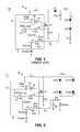
- FIG. 2illustrates an LED driver in accordance with one embodiment of the present invention.
- FIGS. 3A-3Gare examples of various voltage and current waveforms produced by the LED driver of FIG. 2 .
- FIG. 4illustrates an LED driver similar to FIG. 2 but with a voltage mode boost regulator controller, in accordance with another embodiment of the invention.
- FIG. 2illustrates one embodiment of the inventive LED driver 30 .
- the boost controller portion formed on the integrated circuit chip 12may be the same as in FIG. 1 and will not be described again in detail.
- the driver 30is shown driving two parallel strings of LEDs (LED 1 through LEDn and LED 1 A through LEDNA). Any number of LEDs may be connected in series, and any number of strings may be connected in parallel. As the number of LEDs in series increases, the driver 30 automatically increases its boosted output voltage to supply a predetermined average current through the LEDs, where the average current is set by the value of one or more components of the driver 30 .
- the boost controller on chip 12turns the switching transistor Q 1 on and off at a frequency determined by the clock supplying set pulses to the RS flip-flop 24 .
- the frequencywill typically be 1 MHz-3 MHz.
- the duty cycle of the transistor Q 1is controlled by the magnitude of the Vcontrol signal, which is that voltage needed to keep the feedback voltage Vfb into the error amplifier 16 equal to the reference voltage Vref In one embodiment, Vref is a fixed voltage between 0.2 and 2 volts.
- the flip-flop 24When a clock pulse ( FIG. 3A ) is received by the RS flip-flop 24 , the flip-flop 24 turns the switching transistor Q 1 on ( FIG. 3B ), and a ramping current is conducted by the inductor L 1 ( FIG. 3C ) through the transistor Q 1 ( FIG. 3D ) and the resistor R 2 . At this time, no current flows through the LEDs ( FIG. 3E ) since Vout is close to ground.
- the ramping current through the resistor R 2causes the ramping voltage input into the PWM comparator 22 to cross the Vcontrol signal.
- the PWM comparator 22triggers to reset the flip-flop 24 to turn off the transistor Q 1 .
- This triggering time in the cyclesets the instantaneous peak current through the inductor L 1 and the transistor Q 1 ( FIGS. 3C and 3D ).
- the voltage at the inductor L 1then reverses polarity and exceeds the combined forward voltages of the LEDs to turn them on. Because the ramping current through the transistor Q 1 is used to trigger the comparator 22 , the regulator is called a current mode regulator.
- the LED current( FIG. 3E ), provided by the inductor L 1 , ramps down until the beginning of the next clock cycle. During this time, the LEDs are emitting light, and the perceived brightness corresponds to the average current through the LEDs ( FIG. 3E ).
- the average currentmay be set by the user by selecting a value of the current sense resistor Rsense connected in series with the LEDs, through which the LED current flows. A lower value of Rsense will raise Vcontrol to increase the duty cycle to create a higher peak current and a higher average current.
- the pulsing and ramping voltage drop across the Rsenseequal to ILED*Rsense ( FIG.
- the RC filter circuithas a high time constant due to Rfil having a high value, such as 500 ohms. Rfil may have a rating of 1/10 watt.
- a PWM brightness control circuit(not shown), receiving an externally generated brightness control signal, can effectively enable and disable the driver 30 at a relatively low frequency duty cycle, such as 100 Hz-1000 Hz, to dynamically control the average current through the LEDs.
- FIG. 3Gillustrates the Vfb and Vref inputs into the error amplifier 16 .
- Increasing the RC time constantreduces the Vfb ripple.
- the feedback aspect of the boost regulatorvaries the duty cycle to keep Vfb approximately matched to Vref.
- the driver 30is to power 10 LEDs in series with an average current of 40 mA, at an efficiency (eff) of 85%, and Vin is 12 volts. If the voltage drop across each LED is 3 volts, then Vout must be approximately 30 volts, ignoring the voltage drop across the sense resistor Rsense.
- the duty cycle (D) of the switching transistor Q 1equals [Vout ⁇ (Vin*eff)]/Vout, which equals 0.66.
- the filter capacitor Cfilcan be an inexpensive low voltage ceramic type.
- the breakdown voltage of the filter capacitor Cfilmay be about 6 volts, and its value may be on the order of 0.1 ⁇ F.
- the LEDs in FIG. 2are not driven by a constant Vout, smoothed by a large, high voltage capacitor. Rather, in FIG. 2 , the LEDs are driven by a high frequency pulsed current, and the low voltage feedback voltage is smoothed by a small, low voltage capacitor Cfil and resistor Rfil.
- the capacitor Cfilmay be one-tenth the size of the typical output capacitor used in prior art LED drivers.
- the driver components in FIGS. 1 and 2may be selected so that the perceived brightness of the LEDs are identical, but the driver of FIG. 2 will be inherently smaller and less expensive due the use of a smaller capacitor and no blocking diode.
- FIG. 4illustrates an example of an LED driver 40 using a conventional voltage mode boost controller chip 42 , but in conjunction with the inventive feedback circuit.
- the PWM comparator 22compares Vcontrol to a sawtooth waveform generated by an oscillator 44 . No separate clock or flip-flop is used. At the start of the cycle, Vcontrol is greater than the sawtooth signal, and the comparator 22 applies a high gate voltage to the transistor Q 1 to turn it on. When the sawtooth signal crosses Vcontrol, the comparator 22 triggers to turn the transistor Q 1 off. The remainder of the operation is identical to that of FIG. 2 .
- boost controllersmay be used in conjunction with the invention.
- the various componentsmay be coupled together by direct wiring, or via resistors, or via buffers, or via level shifters, or via inverters, or via other components in order to properly operate.
- the polarities of any comparator and op amp inputsmay be the opposite with suitable changes in any affected circuits.
Landscapes
- Dc-Dc Converters (AREA)
- Circuit Arrangement For Electric Light Sources In General (AREA)
Abstract
Description
Claims (20)
Priority Applications (1)
| Application Number | Priority Date | Filing Date | Title |
|---|---|---|---|
| US12/115,471US7919928B2 (en) | 2008-05-05 | 2008-05-05 | Boost LED driver not using output capacitor and blocking diode |
Applications Claiming Priority (1)
| Application Number | Priority Date | Filing Date | Title |
|---|---|---|---|
| US12/115,471US7919928B2 (en) | 2008-05-05 | 2008-05-05 | Boost LED driver not using output capacitor and blocking diode |
Publications (2)
| Publication Number | Publication Date |
|---|---|
| US20090273290A1 US20090273290A1 (en) | 2009-11-05 |
| US7919928B2true US7919928B2 (en) | 2011-04-05 |
Family
ID=41256657
Family Applications (1)
| Application Number | Title | Priority Date | Filing Date |
|---|---|---|---|
| US12/115,471Expired - Fee RelatedUS7919928B2 (en) | 2008-05-05 | 2008-05-05 | Boost LED driver not using output capacitor and blocking diode |
Country Status (1)
| Country | Link |
|---|---|
| US (1) | US7919928B2 (en) |
Cited By (18)
| Publication number | Priority date | Publication date | Assignee | Title |
|---|---|---|---|---|
| US20090141049A1 (en)* | 2007-12-04 | 2009-06-04 | Samsung Electronics Co., Ltd. | Display apparatus for compensating optical parameter using forward voltage of led and method thereof |
| US20100019682A1 (en)* | 2008-07-25 | 2010-01-28 | Chien-Ping Lu | LED driver and controller thereof |
| US20100194299A1 (en)* | 2009-02-05 | 2010-08-05 | Ye Byoung-Dae | Method of driving a light source, light source apparatus for performing the method, and display apparatus having the light source apparatus |
| US20110025234A1 (en)* | 2009-07-31 | 2011-02-03 | Sanyo Electric Co., Ltd. | Light-emitting-element driving circuit |
| US20110156606A1 (en)* | 2009-12-24 | 2011-06-30 | Samsung Electro-Mechanics Co., Ltd. | Light emitting diode driver |
| US8148919B2 (en)* | 2008-08-05 | 2012-04-03 | O2Micro, Inc | Circuits and methods for driving light sources |
| US8237379B2 (en) | 2008-08-05 | 2012-08-07 | O2Micro, Inc. | Circuits and methods for powering light sources |
| JP2012227519A (en)* | 2011-04-14 | 2012-11-15 | O2 Micro Inc | Circuit and method for driving light source |
| TWI392208B (en)* | 2011-10-17 | 2013-04-01 | O2Micro Int Ltd | Driving circuit of light source and methods of powering led light source |
| US20130147358A1 (en)* | 2011-12-07 | 2013-06-13 | Atmel Corporation | Self-Power for Device Driver |
| US20130257313A1 (en)* | 2012-03-29 | 2013-10-03 | Phoseon Technology, Inc. | Load current control circuit |
| TWI427915B (en)* | 2011-08-17 | 2014-02-21 | ||
| US20140176014A1 (en)* | 2012-12-25 | 2014-06-26 | Shenzhen China Star Optoelectronics Technology Co., Ltd. | Led backlight driver circuit |
| TWI483648B (en)* | 2012-08-01 | 2015-05-01 | Nat Applied Res Laboratories | Led driver circuit structure with over current suppression |
| US9320103B2 (en) | 2014-03-06 | 2016-04-19 | Samsung Electronics Co., Ltd. | Light-emitting diode (LED) driver, LED lighting apparatus, and method of operating LED lighting apparatus |
| US20160366730A1 (en)* | 2015-06-10 | 2016-12-15 | Mosway Semiconductor Ltd. | Direct drive led lighting |
| US10034335B1 (en)* | 2017-05-26 | 2018-07-24 | Taiwan Semiconductor Co., Ltd. | Switching mode constant current LED driver |
| US11317497B2 (en) | 2019-06-20 | 2022-04-26 | Express Imaging Systems, Llc | Photocontroller and/or lamp with photocontrols to control operation of lamp |
Families Citing this family (73)
| Publication number | Priority date | Publication date | Assignee | Title |
|---|---|---|---|---|
| KR100867551B1 (en)* | 2007-05-18 | 2008-11-10 | 삼성전기주식회사 | LED array driving device |
| JP4655111B2 (en)* | 2008-05-20 | 2011-03-23 | 日本テキサス・インスツルメンツ株式会社 | LED device and LED drive circuit |
| US7928670B2 (en)* | 2008-06-30 | 2011-04-19 | Iwatt Inc. | LED driver with multiple feedback loops |
| KR101781399B1 (en) | 2008-11-17 | 2017-09-25 | 익스프레스 이미징 시스템즈, 엘엘씨 | Electronic control to regulate power for solid-state lighting and methods thereof |
| TWI407837B (en)* | 2008-12-18 | 2013-09-01 | Novatek Microelectronics Corp | Led illuninant driving circuit and automatic brightness compensation method thereof |
| JP5457684B2 (en)* | 2009-01-20 | 2014-04-02 | 株式会社小糸製作所 | Lighting control device for vehicle lamp |
| US8004201B2 (en)* | 2009-03-06 | 2011-08-23 | Himax Analogic, Inc. | LED circuit |
| US20160212812A9 (en)* | 2009-04-14 | 2016-07-21 | Microchip Technology, Inc. | Led driver with extended dimming range and method for achieving the same |
| US8456106B2 (en)* | 2009-04-14 | 2013-06-04 | Supertex, Inc. | LED driver with extended dimming range and method for achieving the same |
| US8179054B1 (en)* | 2009-04-24 | 2012-05-15 | Zhen Qiu Huang | LED power supply |
| WO2010135575A2 (en) | 2009-05-20 | 2010-11-25 | Express Imaging Systems, Llc | Long-range motion detection for illumination control |
| US9078314B2 (en)* | 2009-08-17 | 2015-07-07 | Point Tek Inc. | Light-emitting diode driving circuit capable of controlling current of light-emitting diode on a full time basis |
| US20110068700A1 (en)* | 2009-09-21 | 2011-03-24 | Suntec Enterprises | Method and apparatus for driving multiple LED devices |
| US8378584B2 (en)* | 2009-12-16 | 2013-02-19 | Semiconductor Components Industries, Llc | Power factor converter and method |
| CN101772242B (en)* | 2010-01-22 | 2014-05-07 | 海洋王照明科技股份有限公司 | LED parallel-current deviation coordinating circuit and navigation lamp |
| US20110216567A1 (en)* | 2010-03-02 | 2011-09-08 | Suntec Enterprises | Single switch inverter |
| US8400131B2 (en)* | 2010-03-09 | 2013-03-19 | Analog Devices, Inc. | Voltage converter and LED driver circuits with progressive boost, skip, and linear mode operation |
| JP5595126B2 (en)* | 2010-06-03 | 2014-09-24 | ローム株式会社 | LED driving device and electronic apparatus equipped with the same |
| TWI423721B (en)* | 2010-08-11 | 2014-01-11 | Excelliance Mos Corp | Driving device for led module |
| US8531131B2 (en)* | 2010-09-22 | 2013-09-10 | Osram Sylvania Inc. | Auto-sensing switching regulator to drive a light source through a current regulator |
| TW201215231A (en)* | 2010-09-29 | 2012-04-01 | Power Forest Technology | Driving circuit of light emitting diodes and short circuit protection circuit applied to a driving circuit of light emitting diodes |
| KR101167201B1 (en)* | 2010-11-10 | 2012-07-24 | 매그나칩 반도체 유한회사 | Pwm signal generating circuit for dc-dc converter using diming signal and led driver circuit having the same in direct digital dimming method |
| CN102076149B (en)* | 2010-11-15 | 2012-01-04 | 凹凸电子(武汉)有限公司 | Light source drive circuit, controller and method for controlling light source brightness |
| US9143033B2 (en)* | 2010-11-30 | 2015-09-22 | Taiwan Semiconductor Manufacturing Company, Ltd. | Hysteretic power converter with calibration circuit |
| KR20120080907A (en)* | 2011-01-10 | 2012-07-18 | 페어차일드코리아반도체 주식회사 | Light emitting diode emitting device |
| US8476843B2 (en)* | 2011-01-17 | 2013-07-02 | TPV Electronics (Fujian) Co., Ltd. | Driving circuit for single-string LED lamp |
| US8928297B2 (en)* | 2011-01-31 | 2015-01-06 | Infineon Technologies Austria Ag | Ćuk based current source |
| US8901825B2 (en) | 2011-04-12 | 2014-12-02 | Express Imaging Systems, Llc | Apparatus and method of energy efficient illumination using received signals |
| TWI469686B (en)* | 2011-05-10 | 2015-01-11 | Richtek Technology Corp | Light emitting device current regulator circuit and control method thereof |
| US9060397B2 (en)* | 2011-07-15 | 2015-06-16 | General Electric Company | High voltage LED and driver |
| TW201306642A (en)* | 2011-07-19 | 2013-02-01 | Starchips Technology Inc | Lighting apparatus and driving circuit thereof |
| US9357600B2 (en) | 2011-08-15 | 2016-05-31 | Koninklijke Philips N.V. | Electronic ballast-compatible lighting driver for light-emitting diode lamp |
| EP2745387A1 (en) | 2011-09-30 | 2014-06-25 | Koninklijke Philips N.V. | Active capacitor circuit |
| US9360198B2 (en)* | 2011-12-06 | 2016-06-07 | Express Imaging Systems, Llc | Adjustable output solid-state lighting device |
| US9497393B2 (en) | 2012-03-02 | 2016-11-15 | Express Imaging Systems, Llc | Systems and methods that employ object recognition |
| US9588171B2 (en) | 2012-05-16 | 2017-03-07 | Infineon Technologies Ag | System and method for testing an integrated circuit |
| CN102695341B (en)* | 2012-05-28 | 2014-07-16 | 矽力杰半导体技术(杭州)有限公司 | LED drive power supply applicable to electronic transformer |
| US9131552B2 (en) | 2012-07-25 | 2015-09-08 | Express Imaging Systems, Llc | Apparatus and method of operating a luminaire |
| US8816604B2 (en)* | 2012-08-03 | 2014-08-26 | Ge Lighting Solutions, Llc. | Dimming control method and apparatus for LED light source |
| US8963706B2 (en)* | 2012-08-06 | 2015-02-24 | Shindengen Electric Manufacturing Co., Ltd. | Direction indicating apparatus |
| EP2881286B1 (en)* | 2012-08-06 | 2018-05-23 | Shindengen Electric Manufacturing Co., Ltd. | Direction-indication device |
| TW201410065A (en)* | 2012-08-28 | 2014-03-01 | Luxul Technology Inc | Bucked linear LED driving circuit using serial and parallel connections of capacitors |
| US8896215B2 (en) | 2012-09-05 | 2014-11-25 | Express Imaging Systems, Llc | Apparatus and method for schedule based operation of a luminaire |
| US9107246B2 (en)* | 2012-09-05 | 2015-08-11 | Phoseon Technology, Inc. | Method and system for shutting down a lighting device |
| TWI484859B (en)* | 2012-09-07 | 2015-05-11 | Raydium Semiconductor Corp | Driving circuit and the ralated circuit driving method |
| US20150237701A1 (en)* | 2012-11-16 | 2015-08-20 | Beyond Innovation Technology Co., Ltd. | Load driving apparatus related to light emitting diodes |
| KR101961116B1 (en)* | 2012-11-19 | 2019-03-25 | 삼성디스플레이 주식회사 | Power control device and display devince comprising the same |
| CN103065589B (en)* | 2012-12-19 | 2016-02-03 | 深圳市华星光电技术有限公司 | A kind of backlight drive circuit and liquid crystal display |
| US9288873B2 (en) | 2013-02-13 | 2016-03-15 | Express Imaging Systems, Llc | Systems, methods, and apparatuses for using a high current switching device as a logic level sensor |
| US9055634B2 (en)* | 2013-04-17 | 2015-06-09 | Kevin McDermott | Light emitting diode lighting device |
| TW201448663A (en)* | 2013-05-23 | 2014-12-16 | Zentr Mikroelekt Dresden Gmbh | Assembly and a method for activating leds |
| US9466443B2 (en) | 2013-07-24 | 2016-10-11 | Express Imaging Systems, Llc | Photocontrol for luminaire consumes very low power |
| JP6167400B2 (en)* | 2013-08-02 | 2017-07-26 | パナソニックIpマネジメント株式会社 | Lighting device, lighting fixture, lighting device design method, and lighting device manufacturing method |
| US9414449B2 (en) | 2013-11-18 | 2016-08-09 | Express Imaging Systems, Llc | High efficiency power controller for luminaire |
| WO2016054085A1 (en) | 2014-09-30 | 2016-04-07 | Express Imaging Systems, Llc | Centralized control of area lighting hours of illumination |
| US9445485B2 (en) | 2014-10-24 | 2016-09-13 | Express Imaging Systems, Llc | Detection and correction of faulty photo controls in outdoor luminaires |
| US9462662B1 (en) | 2015-03-24 | 2016-10-04 | Express Imaging Systems, Llc | Low power photocontrol for luminaire |
| CN107635312A (en)* | 2015-06-19 | 2018-01-26 | 青岛海信电器股份有限公司 | A kind of LED drive circuit and liquid crystal display device |
| US9538612B1 (en) | 2015-09-03 | 2017-01-03 | Express Imaging Systems, Llc | Low power photocontrol for luminaire |
| US9801242B2 (en)* | 2015-09-29 | 2017-10-24 | Skyworks Soluteqns, Enc. | Apparatus and methods for boost regulators with dynamic regulation band |
| ITUB20159597A1 (en) | 2015-12-23 | 2017-06-23 | St Microelectronics Srl | INTEGRATED DEVICE AND METHOD OF PILOTING LIGHTING LOADS WITH BRIGHTNESS COMPENSATION |
| US9924582B2 (en) | 2016-04-26 | 2018-03-20 | Express Imaging Systems, Llc | Luminaire dimming module uses 3 contact NEMA photocontrol socket |
| JP6692069B2 (en)* | 2016-04-27 | 2020-05-13 | パナソニックIpマネジメント株式会社 | Power supply and lighting device |
| US10230296B2 (en) | 2016-09-21 | 2019-03-12 | Express Imaging Systems, Llc | Output ripple reduction for power converters |
| US9985429B2 (en) | 2016-09-21 | 2018-05-29 | Express Imaging Systems, Llc | Inrush current limiter circuit |
| US10904992B2 (en) | 2017-04-03 | 2021-01-26 | Express Imaging Systems, Llc | Systems and methods for outdoor luminaire wireless control |
| US11375599B2 (en) | 2017-04-03 | 2022-06-28 | Express Imaging Systems, Llc | Systems and methods for outdoor luminaire wireless control |
| JP6867228B2 (en)* | 2017-05-24 | 2021-04-28 | 株式会社小糸製作所 | Luminous drive, vehicle lighting |
| US20190327793A1 (en)* | 2018-04-23 | 2019-10-24 | Whirlpool Corporation | System and method for controlling induction heating devices with series connected switching devices |
| CN110881158B (en)* | 2018-09-06 | 2021-09-28 | 芯洲科技(北京)有限公司 | Integrated circuit device and audio playback device |
| US11212887B2 (en) | 2019-11-04 | 2021-12-28 | Express Imaging Systems, Llc | Light having selectively adjustable sets of solid state light sources, circuit and method of operation thereof, to provide variable output characteristics |
| CN114220369B (en)* | 2022-01-06 | 2023-08-01 | 苏州华星光电技术有限公司 | Driving circuit, driving method and display terminal |
| US12439488B2 (en) | 2022-12-09 | 2025-10-07 | Express Imaging Systems, Llc | Field adjustable output for dimmable luminaires |
Citations (4)
| Publication number | Priority date | Publication date | Assignee | Title |
|---|---|---|---|---|
| US6285139B1 (en)* | 1999-12-23 | 2001-09-04 | Gelcore, Llc | Non-linear light-emitting load current control |
| US7122971B2 (en)* | 2003-11-05 | 2006-10-17 | Richtek Technology Corp. | Driver circuit for driving a plurality of DC lamp strings |
| US7550934B1 (en)* | 2008-04-02 | 2009-06-23 | Micrel, Inc. | LED driver with fast open circuit protection, short circuit compensation, and rapid brightness control response |
| US7671575B1 (en)* | 2006-11-07 | 2010-03-02 | National Semiconductor Corporation | Transient load response for a voltage regulator with a load current based control loop |
- 2008
- 2008-05-05USUS12/115,471patent/US7919928B2/ennot_activeExpired - Fee Related
Patent Citations (4)
| Publication number | Priority date | Publication date | Assignee | Title |
|---|---|---|---|---|
| US6285139B1 (en)* | 1999-12-23 | 2001-09-04 | Gelcore, Llc | Non-linear light-emitting load current control |
| US7122971B2 (en)* | 2003-11-05 | 2006-10-17 | Richtek Technology Corp. | Driver circuit for driving a plurality of DC lamp strings |
| US7671575B1 (en)* | 2006-11-07 | 2010-03-02 | National Semiconductor Corporation | Transient load response for a voltage regulator with a load current based control loop |
| US7550934B1 (en)* | 2008-04-02 | 2009-06-23 | Micrel, Inc. | LED driver with fast open circuit protection, short circuit compensation, and rapid brightness control response |
Cited By (28)
| Publication number | Priority date | Publication date | Assignee | Title |
|---|---|---|---|---|
| US20090141049A1 (en)* | 2007-12-04 | 2009-06-04 | Samsung Electronics Co., Ltd. | Display apparatus for compensating optical parameter using forward voltage of led and method thereof |
| US8169159B2 (en)* | 2008-07-25 | 2012-05-01 | Richtek Technology Corp. | Boost converter LED driver and controller thereof |
| US20100019682A1 (en)* | 2008-07-25 | 2010-01-28 | Chien-Ping Lu | LED driver and controller thereof |
| US8253352B2 (en) | 2008-08-05 | 2012-08-28 | O2Micro, Inc. | Circuits and methods for powering light sources |
| US8148919B2 (en)* | 2008-08-05 | 2012-04-03 | O2Micro, Inc | Circuits and methods for driving light sources |
| US8237379B2 (en) | 2008-08-05 | 2012-08-07 | O2Micro, Inc. | Circuits and methods for powering light sources |
| US8395325B2 (en)* | 2009-02-05 | 2013-03-12 | Samsung Display Co., Ltd. | Method of driving a light source, light source apparatus for performing the method, and display apparatus having the light source apparatus |
| US20100194299A1 (en)* | 2009-02-05 | 2010-08-05 | Ye Byoung-Dae | Method of driving a light source, light source apparatus for performing the method, and display apparatus having the light source apparatus |
| US20110025234A1 (en)* | 2009-07-31 | 2011-02-03 | Sanyo Electric Co., Ltd. | Light-emitting-element driving circuit |
| US8228005B2 (en)* | 2009-07-31 | 2012-07-24 | Semiconductor Components Industries, Llc | Light-emitting-element driving circuit |
| US20110156606A1 (en)* | 2009-12-24 | 2011-06-30 | Samsung Electro-Mechanics Co., Ltd. | Light emitting diode driver |
| US8344662B2 (en)* | 2009-12-24 | 2013-01-01 | Samsung Electro-Mechanics Co., Ltd. | Light emitting diode driver |
| JP2012227519A (en)* | 2011-04-14 | 2012-11-15 | O2 Micro Inc | Circuit and method for driving light source |
| TWI427915B (en)* | 2011-08-17 | 2014-02-21 | ||
| TWI392208B (en)* | 2011-10-17 | 2013-04-01 | O2Micro Int Ltd | Driving circuit of light source and methods of powering led light source |
| US20130147358A1 (en)* | 2011-12-07 | 2013-06-13 | Atmel Corporation | Self-Power for Device Driver |
| US8604699B2 (en)* | 2011-12-07 | 2013-12-10 | Atmel Corporation | Self-power for device driver |
| US20130257313A1 (en)* | 2012-03-29 | 2013-10-03 | Phoseon Technology, Inc. | Load current control circuit |
| US9277623B2 (en)* | 2012-03-29 | 2016-03-01 | Phoseon Technology, Inc. | Load current control circuit |
| US9867252B2 (en) | 2012-03-29 | 2018-01-09 | Phoseon Technology, Inc. | Load current control circuit |
| TWI483648B (en)* | 2012-08-01 | 2015-05-01 | Nat Applied Res Laboratories | Led driver circuit structure with over current suppression |
| US20140176014A1 (en)* | 2012-12-25 | 2014-06-26 | Shenzhen China Star Optoelectronics Technology Co., Ltd. | Led backlight driver circuit |
| US9230490B2 (en)* | 2012-12-25 | 2016-01-05 | Shenzhen China Star Optoelectronics Technology Co., Ltd | LED backlight driver circuit |
| US9320103B2 (en) | 2014-03-06 | 2016-04-19 | Samsung Electronics Co., Ltd. | Light-emitting diode (LED) driver, LED lighting apparatus, and method of operating LED lighting apparatus |
| US20160366730A1 (en)* | 2015-06-10 | 2016-12-15 | Mosway Semiconductor Ltd. | Direct drive led lighting |
| US10187943B2 (en)* | 2015-06-10 | 2019-01-22 | Mosway Semiconductor Ltd. | Direct drive LED lighting |
| US10034335B1 (en)* | 2017-05-26 | 2018-07-24 | Taiwan Semiconductor Co., Ltd. | Switching mode constant current LED driver |
| US11317497B2 (en) | 2019-06-20 | 2022-04-26 | Express Imaging Systems, Llc | Photocontroller and/or lamp with photocontrols to control operation of lamp |
Also Published As
| Publication number | Publication date |
|---|---|
| US20090273290A1 (en) | 2009-11-05 |
Similar Documents
| Publication | Publication Date | Title |
|---|---|---|
| US7919928B2 (en) | Boost LED driver not using output capacitor and blocking diode | |
| KR101835255B1 (en) | Boost then floating buck mode converter for led driver using common switch control signal | |
| US8044608B2 (en) | Driving circuit with dimming controller for driving light sources | |
| US8482219B2 (en) | Driving circuit with dimming controller for driving light sources | |
| US8716949B2 (en) | Lighting device for solid-state light source and illumination apparatus using same | |
| US8330388B2 (en) | Circuits and methods for driving light sources | |
| US20130278145A1 (en) | Circuits and methods for driving light sources | |
| US9232591B2 (en) | Circuits and methods for driving light sources | |
| US8508150B2 (en) | Controllers, systems and methods for controlling dimming of light sources | |
| US9386653B2 (en) | Circuits and methods for driving light sources | |
| US9030122B2 (en) | Circuits and methods for driving LED light sources | |
| CN102695328B (en) | Lamp device and lighting apparatus | |
| US20110227496A1 (en) | Circuits and methods for driving light sources | |
| EP2498579A2 (en) | Controllers, systems and methods for controlling dimming of light sources | |
| KR20120102535A (en) | Control circuit of switching power supply for driving light emitting elements, and light emitting device and electronic apparatus using the same | |
| US20120262079A1 (en) | Circuits and methods for driving light sources | |
| EP3491891B1 (en) | Dimming led circuit augmenting dc/dc controller integrated circuit | |
| US9730286B2 (en) | Control circuit and method for generating voltage for light emitting diode lighting device | |
| GB2503316A (en) | Circuits and methods for driving light sources | |
| US9723668B2 (en) | Switching converter and lighting device using the same | |
| CN102752906B (en) | Lighting device and illumination apparatus having the same | |
| US9287775B2 (en) | Power supply device and lighting device | |
| GB2513478A (en) | Circuits and methods for driving light sources | |
| JP6791486B2 (en) | Light emitting element drive device and its drive method | |
| KR101807103B1 (en) | Ac direct driving led apparatus |
Legal Events
| Date | Code | Title | Description |
|---|---|---|---|
| AS | Assignment | Owner name:MICREL, INC., CALIFORNIA Free format text:ASSIGNMENT OF ASSIGNORS INTEREST;ASSIGNOR:ZIEGENFUSS, MARK;REEL/FRAME:020904/0761 Effective date:20080501 | |
| STCF | Information on status: patent grant | Free format text:PATENTED CASE | |
| FPAY | Fee payment | Year of fee payment:4 | |
| MAFP | Maintenance fee payment | Free format text:PAYMENT OF MAINTENANCE FEE, 8TH YEAR, LARGE ENTITY (ORIGINAL EVENT CODE: M1552); ENTITY STATUS OF PATENT OWNER: LARGE ENTITY Year of fee payment:8 | |
| AS | Assignment | Owner name:JPMORGAN CHASE BANK, N.A., AS ADMINISTRATIVE AGENT, DELAWARE Free format text:SECURITY INTEREST;ASSIGNORS:MICROCHIP TECHNOLOGY INC.;SILICON STORAGE TECHNOLOGY, INC.;ATMEL CORPORATION;AND OTHERS;REEL/FRAME:053311/0305 Effective date:20200327 | |
| AS | Assignment | Owner name:SILICON STORAGE TECHNOLOGY, INC., ARIZONA Free format text:RELEASE BY SECURED PARTY;ASSIGNOR:JPMORGAN CHASE BANK, N.A, AS ADMINISTRATIVE AGENT;REEL/FRAME:053466/0011 Effective date:20200529 Owner name:ATMEL CORPORATION, ARIZONA Free format text:RELEASE BY SECURED PARTY;ASSIGNOR:JPMORGAN CHASE BANK, N.A, AS ADMINISTRATIVE AGENT;REEL/FRAME:053466/0011 Effective date:20200529 Owner name:MICROSEMI CORPORATION, CALIFORNIA Free format text:RELEASE BY SECURED PARTY;ASSIGNOR:JPMORGAN CHASE BANK, N.A, AS ADMINISTRATIVE AGENT;REEL/FRAME:053466/0011 Effective date:20200529 Owner name:MICROCHIP TECHNOLOGY INC., ARIZONA Free format text:RELEASE BY SECURED PARTY;ASSIGNOR:JPMORGAN CHASE BANK, N.A, AS ADMINISTRATIVE AGENT;REEL/FRAME:053466/0011 Effective date:20200529 Owner name:MICROSEMI STORAGE SOLUTIONS, INC., ARIZONA Free format text:RELEASE BY SECURED PARTY;ASSIGNOR:JPMORGAN CHASE BANK, N.A, AS ADMINISTRATIVE AGENT;REEL/FRAME:053466/0011 Effective date:20200529 | |
| AS | Assignment | Owner name:WELLS FARGO BANK, NATIONAL ASSOCIATION, MINNESOTA Free format text:SECURITY INTEREST;ASSIGNORS:MICROCHIP TECHNOLOGY INC.;SILICON STORAGE TECHNOLOGY, INC.;ATMEL CORPORATION;AND OTHERS;REEL/FRAME:053468/0705 Effective date:20200529 | |
| AS | Assignment | Owner name:WELLS FARGO BANK, NATIONAL ASSOCIATION, AS COLLATERAL AGENT, MINNESOTA Free format text:SECURITY INTEREST;ASSIGNORS:MICROCHIP TECHNOLOGY INCORPORATED;SILICON STORAGE TECHNOLOGY, INC.;ATMEL CORPORATION;AND OTHERS;REEL/FRAME:055671/0612 Effective date:20201217 | |
| AS | Assignment | Owner name:WELLS FARGO BANK, NATIONAL ASSOCIATION, AS NOTES COLLATERAL AGENT, MINNESOTA Free format text:SECURITY INTEREST;ASSIGNORS:MICROCHIP TECHNOLOGY INCORPORATED;SILICON STORAGE TECHNOLOGY, INC.;ATMEL CORPORATION;AND OTHERS;REEL/FRAME:057935/0474 Effective date:20210528 | |
| AS | Assignment | Owner name:MICROSEMI STORAGE SOLUTIONS, INC., ARIZONA Free format text:RELEASE BY SECURED PARTY;ASSIGNOR:WELLS FARGO BANK, NATIONAL ASSOCIATION, AS NOTES COLLATERAL AGENT;REEL/FRAME:059863/0400 Effective date:20220228 Owner name:MICROSEMI CORPORATION, ARIZONA Free format text:RELEASE BY SECURED PARTY;ASSIGNOR:WELLS FARGO BANK, NATIONAL ASSOCIATION, AS NOTES COLLATERAL AGENT;REEL/FRAME:059863/0400 Effective date:20220228 Owner name:ATMEL CORPORATION, ARIZONA Free format text:RELEASE BY SECURED PARTY;ASSIGNOR:WELLS FARGO BANK, NATIONAL ASSOCIATION, AS NOTES COLLATERAL AGENT;REEL/FRAME:059863/0400 Effective date:20220228 Owner name:SILICON STORAGE TECHNOLOGY, INC., ARIZONA Free format text:RELEASE BY SECURED PARTY;ASSIGNOR:WELLS FARGO BANK, NATIONAL ASSOCIATION, AS NOTES COLLATERAL AGENT;REEL/FRAME:059863/0400 Effective date:20220228 Owner name:MICROCHIP TECHNOLOGY INCORPORATED, ARIZONA Free format text:RELEASE BY SECURED PARTY;ASSIGNOR:WELLS FARGO BANK, NATIONAL ASSOCIATION, AS NOTES COLLATERAL AGENT;REEL/FRAME:059863/0400 Effective date:20220228 | |
| AS | Assignment | Owner name:MICROSEMI STORAGE SOLUTIONS, INC., ARIZONA Free format text:RELEASE BY SECURED PARTY;ASSIGNOR:WELLS FARGO BANK, NATIONAL ASSOCIATION, AS NOTES COLLATERAL AGENT;REEL/FRAME:059363/0001 Effective date:20220228 Owner name:MICROSEMI CORPORATION, ARIZONA Free format text:RELEASE BY SECURED PARTY;ASSIGNOR:WELLS FARGO BANK, NATIONAL ASSOCIATION, AS NOTES COLLATERAL AGENT;REEL/FRAME:059363/0001 Effective date:20220228 Owner name:ATMEL CORPORATION, ARIZONA Free format text:RELEASE BY SECURED PARTY;ASSIGNOR:WELLS FARGO BANK, NATIONAL ASSOCIATION, AS NOTES COLLATERAL AGENT;REEL/FRAME:059363/0001 Effective date:20220228 Owner name:SILICON STORAGE TECHNOLOGY, INC., ARIZONA Free format text:RELEASE BY SECURED PARTY;ASSIGNOR:WELLS FARGO BANK, NATIONAL ASSOCIATION, AS NOTES COLLATERAL AGENT;REEL/FRAME:059363/0001 Effective date:20220228 Owner name:MICROCHIP TECHNOLOGY INCORPORATED, ARIZONA Free format text:RELEASE BY SECURED PARTY;ASSIGNOR:WELLS FARGO BANK, NATIONAL ASSOCIATION, AS NOTES COLLATERAL AGENT;REEL/FRAME:059363/0001 Effective date:20220228 | |
| AS | Assignment | Owner name:MICROSEMI STORAGE SOLUTIONS, INC., ARIZONA Free format text:RELEASE BY SECURED PARTY;ASSIGNOR:WELLS FARGO BANK, NATIONAL ASSOCIATION, AS NOTES COLLATERAL AGENT;REEL/FRAME:060894/0437 Effective date:20220228 Owner name:MICROSEMI CORPORATION, ARIZONA Free format text:RELEASE BY SECURED PARTY;ASSIGNOR:WELLS FARGO BANK, NATIONAL ASSOCIATION, AS NOTES COLLATERAL AGENT;REEL/FRAME:060894/0437 Effective date:20220228 Owner name:ATMEL CORPORATION, ARIZONA Free format text:RELEASE BY SECURED PARTY;ASSIGNOR:WELLS FARGO BANK, NATIONAL ASSOCIATION, AS NOTES COLLATERAL AGENT;REEL/FRAME:060894/0437 Effective date:20220228 Owner name:SILICON STORAGE TECHNOLOGY, INC., ARIZONA Free format text:RELEASE BY SECURED PARTY;ASSIGNOR:WELLS FARGO BANK, NATIONAL ASSOCIATION, AS NOTES COLLATERAL AGENT;REEL/FRAME:060894/0437 Effective date:20220228 Owner name:MICROCHIP TECHNOLOGY INCORPORATED, ARIZONA Free format text:RELEASE BY SECURED PARTY;ASSIGNOR:WELLS FARGO BANK, NATIONAL ASSOCIATION, AS NOTES COLLATERAL AGENT;REEL/FRAME:060894/0437 Effective date:20220228 | |
| FEPP | Fee payment procedure | Free format text:MAINTENANCE FEE REMINDER MAILED (ORIGINAL EVENT CODE: REM.); ENTITY STATUS OF PATENT OWNER: LARGE ENTITY | |
| LAPS | Lapse for failure to pay maintenance fees | Free format text:PATENT EXPIRED FOR FAILURE TO PAY MAINTENANCE FEES (ORIGINAL EVENT CODE: EXP.); ENTITY STATUS OF PATENT OWNER: LARGE ENTITY | |
| STCH | Information on status: patent discontinuation | Free format text:PATENT EXPIRED DUE TO NONPAYMENT OF MAINTENANCE FEES UNDER 37 CFR 1.362 | |
| FP | Lapsed due to failure to pay maintenance fee | Effective date:20230405 |