US7918889B2 - Expandable spinal prosthetic devices and associated methods - Google Patents
Expandable spinal prosthetic devices and associated methodsDownload PDFInfo
- Publication number
- US7918889B2 US7918889B2US11/362,998US36299806AUS7918889B2US 7918889 B2US7918889 B2US 7918889B2US 36299806 AUS36299806 AUS 36299806AUS 7918889 B2US7918889 B2US 7918889B2
- Authority
- US
- United States
- Prior art keywords
- articulation
- expandable member
- members
- expandable
- tacks
- Prior art date
- Legal status (The legal status is an assumption and is not a legal conclusion. Google has not performed a legal analysis and makes no representation as to the accuracy of the status listed.)
- Expired - Fee Related, expires
Links
Images


Classifications
- A—HUMAN NECESSITIES
- A61—MEDICAL OR VETERINARY SCIENCE; HYGIENE
- A61F—FILTERS IMPLANTABLE INTO BLOOD VESSELS; PROSTHESES; DEVICES PROVIDING PATENCY TO, OR PREVENTING COLLAPSING OF, TUBULAR STRUCTURES OF THE BODY, e.g. STENTS; ORTHOPAEDIC, NURSING OR CONTRACEPTIVE DEVICES; FOMENTATION; TREATMENT OR PROTECTION OF EYES OR EARS; BANDAGES, DRESSINGS OR ABSORBENT PADS; FIRST-AID KITS
- A61F2/00—Filters implantable into blood vessels; Prostheses, i.e. artificial substitutes or replacements for parts of the body; Appliances for connecting them with the body; Devices providing patency to, or preventing collapsing of, tubular structures of the body, e.g. stents
- A61F2/02—Prostheses implantable into the body
- A61F2/30—Joints
- A61F2/44—Joints for the spine, e.g. vertebrae, spinal discs
- A61F2/442—Intervertebral or spinal discs, e.g. resilient
- A61F2/4425—Intervertebral or spinal discs, e.g. resilient made of articulated components
- A—HUMAN NECESSITIES
- A61—MEDICAL OR VETERINARY SCIENCE; HYGIENE
- A61F—FILTERS IMPLANTABLE INTO BLOOD VESSELS; PROSTHESES; DEVICES PROVIDING PATENCY TO, OR PREVENTING COLLAPSING OF, TUBULAR STRUCTURES OF THE BODY, e.g. STENTS; ORTHOPAEDIC, NURSING OR CONTRACEPTIVE DEVICES; FOMENTATION; TREATMENT OR PROTECTION OF EYES OR EARS; BANDAGES, DRESSINGS OR ABSORBENT PADS; FIRST-AID KITS
- A61F2/00—Filters implantable into blood vessels; Prostheses, i.e. artificial substitutes or replacements for parts of the body; Appliances for connecting them with the body; Devices providing patency to, or preventing collapsing of, tubular structures of the body, e.g. stents
- A61F2/02—Prostheses implantable into the body
- A61F2/30—Joints
- A61F2/3094—Designing or manufacturing processes
- A61F2/30965—Reinforcing the prosthesis by embedding particles or fibres during moulding or dipping
- A—HUMAN NECESSITIES
- A61—MEDICAL OR VETERINARY SCIENCE; HYGIENE
- A61F—FILTERS IMPLANTABLE INTO BLOOD VESSELS; PROSTHESES; DEVICES PROVIDING PATENCY TO, OR PREVENTING COLLAPSING OF, TUBULAR STRUCTURES OF THE BODY, e.g. STENTS; ORTHOPAEDIC, NURSING OR CONTRACEPTIVE DEVICES; FOMENTATION; TREATMENT OR PROTECTION OF EYES OR EARS; BANDAGES, DRESSINGS OR ABSORBENT PADS; FIRST-AID KITS
- A61F2/00—Filters implantable into blood vessels; Prostheses, i.e. artificial substitutes or replacements for parts of the body; Appliances for connecting them with the body; Devices providing patency to, or preventing collapsing of, tubular structures of the body, e.g. stents
- A61F2/02—Prostheses implantable into the body
- A61F2/30—Joints
- A61F2/44—Joints for the spine, e.g. vertebrae, spinal discs
- A61F2/441—Joints for the spine, e.g. vertebrae, spinal discs made of inflatable pockets or chambers filled with fluid, e.g. with hydrogel
- A—HUMAN NECESSITIES
- A61—MEDICAL OR VETERINARY SCIENCE; HYGIENE
- A61F—FILTERS IMPLANTABLE INTO BLOOD VESSELS; PROSTHESES; DEVICES PROVIDING PATENCY TO, OR PREVENTING COLLAPSING OF, TUBULAR STRUCTURES OF THE BODY, e.g. STENTS; ORTHOPAEDIC, NURSING OR CONTRACEPTIVE DEVICES; FOMENTATION; TREATMENT OR PROTECTION OF EYES OR EARS; BANDAGES, DRESSINGS OR ABSORBENT PADS; FIRST-AID KITS
- A61F2/00—Filters implantable into blood vessels; Prostheses, i.e. artificial substitutes or replacements for parts of the body; Appliances for connecting them with the body; Devices providing patency to, or preventing collapsing of, tubular structures of the body, e.g. stents
- A61F2/02—Prostheses implantable into the body
- A61F2/30—Joints
- A61F2/46—Special tools for implanting artificial joints
- A61F2/4603—Special tools for implanting artificial joints for insertion or extraction of endoprosthetic joints or of accessories thereof
- A61F2/4611—Special tools for implanting artificial joints for insertion or extraction of endoprosthetic joints or of accessories thereof of spinal prostheses
- A—HUMAN NECESSITIES
- A61—MEDICAL OR VETERINARY SCIENCE; HYGIENE
- A61F—FILTERS IMPLANTABLE INTO BLOOD VESSELS; PROSTHESES; DEVICES PROVIDING PATENCY TO, OR PREVENTING COLLAPSING OF, TUBULAR STRUCTURES OF THE BODY, e.g. STENTS; ORTHOPAEDIC, NURSING OR CONTRACEPTIVE DEVICES; FOMENTATION; TREATMENT OR PROTECTION OF EYES OR EARS; BANDAGES, DRESSINGS OR ABSORBENT PADS; FIRST-AID KITS
- A61F2/00—Filters implantable into blood vessels; Prostheses, i.e. artificial substitutes or replacements for parts of the body; Appliances for connecting them with the body; Devices providing patency to, or preventing collapsing of, tubular structures of the body, e.g. stents
- A61F2/02—Prostheses implantable into the body
- A61F2/30—Joints
- A61F2/30767—Special external or bone-contacting surface, e.g. coating for improving bone ingrowth
- A—HUMAN NECESSITIES
- A61—MEDICAL OR VETERINARY SCIENCE; HYGIENE
- A61F—FILTERS IMPLANTABLE INTO BLOOD VESSELS; PROSTHESES; DEVICES PROVIDING PATENCY TO, OR PREVENTING COLLAPSING OF, TUBULAR STRUCTURES OF THE BODY, e.g. STENTS; ORTHOPAEDIC, NURSING OR CONTRACEPTIVE DEVICES; FOMENTATION; TREATMENT OR PROTECTION OF EYES OR EARS; BANDAGES, DRESSINGS OR ABSORBENT PADS; FIRST-AID KITS
- A61F2/00—Filters implantable into blood vessels; Prostheses, i.e. artificial substitutes or replacements for parts of the body; Appliances for connecting them with the body; Devices providing patency to, or preventing collapsing of, tubular structures of the body, e.g. stents
- A61F2/02—Prostheses implantable into the body
- A61F2/30—Joints
- A61F2/46—Special tools for implanting artificial joints
- A61F2/4684—Trial or dummy prostheses
- A—HUMAN NECESSITIES
- A61—MEDICAL OR VETERINARY SCIENCE; HYGIENE
- A61F—FILTERS IMPLANTABLE INTO BLOOD VESSELS; PROSTHESES; DEVICES PROVIDING PATENCY TO, OR PREVENTING COLLAPSING OF, TUBULAR STRUCTURES OF THE BODY, e.g. STENTS; ORTHOPAEDIC, NURSING OR CONTRACEPTIVE DEVICES; FOMENTATION; TREATMENT OR PROTECTION OF EYES OR EARS; BANDAGES, DRESSINGS OR ABSORBENT PADS; FIRST-AID KITS
- A61F2/00—Filters implantable into blood vessels; Prostheses, i.e. artificial substitutes or replacements for parts of the body; Appliances for connecting them with the body; Devices providing patency to, or preventing collapsing of, tubular structures of the body, e.g. stents
- A61F2/02—Prostheses implantable into the body
- A61F2/30—Joints
- A61F2002/30001—Additional features of subject-matter classified in A61F2/28, A61F2/30 and subgroups thereof
- A61F2002/30003—Material related properties of the prosthesis or of a coating on the prosthesis
- A61F2002/3006—Properties of materials and coating materials
- A61F2002/30062—(bio)absorbable, biodegradable, bioerodable, (bio)resorbable, resorptive
- A—HUMAN NECESSITIES
- A61—MEDICAL OR VETERINARY SCIENCE; HYGIENE
- A61F—FILTERS IMPLANTABLE INTO BLOOD VESSELS; PROSTHESES; DEVICES PROVIDING PATENCY TO, OR PREVENTING COLLAPSING OF, TUBULAR STRUCTURES OF THE BODY, e.g. STENTS; ORTHOPAEDIC, NURSING OR CONTRACEPTIVE DEVICES; FOMENTATION; TREATMENT OR PROTECTION OF EYES OR EARS; BANDAGES, DRESSINGS OR ABSORBENT PADS; FIRST-AID KITS
- A61F2/00—Filters implantable into blood vessels; Prostheses, i.e. artificial substitutes or replacements for parts of the body; Appliances for connecting them with the body; Devices providing patency to, or preventing collapsing of, tubular structures of the body, e.g. stents
- A61F2/02—Prostheses implantable into the body
- A61F2/30—Joints
- A61F2002/30001—Additional features of subject-matter classified in A61F2/28, A61F2/30 and subgroups thereof
- A61F2002/30003—Material related properties of the prosthesis or of a coating on the prosthesis
- A61F2002/3006—Properties of materials and coating materials
- A61F2002/3008—Properties of materials and coating materials radio-opaque, e.g. radio-opaque markers
- A—HUMAN NECESSITIES
- A61—MEDICAL OR VETERINARY SCIENCE; HYGIENE
- A61F—FILTERS IMPLANTABLE INTO BLOOD VESSELS; PROSTHESES; DEVICES PROVIDING PATENCY TO, OR PREVENTING COLLAPSING OF, TUBULAR STRUCTURES OF THE BODY, e.g. STENTS; ORTHOPAEDIC, NURSING OR CONTRACEPTIVE DEVICES; FOMENTATION; TREATMENT OR PROTECTION OF EYES OR EARS; BANDAGES, DRESSINGS OR ABSORBENT PADS; FIRST-AID KITS
- A61F2/00—Filters implantable into blood vessels; Prostheses, i.e. artificial substitutes or replacements for parts of the body; Appliances for connecting them with the body; Devices providing patency to, or preventing collapsing of, tubular structures of the body, e.g. stents
- A61F2/02—Prostheses implantable into the body
- A61F2/30—Joints
- A61F2002/30001—Additional features of subject-matter classified in A61F2/28, A61F2/30 and subgroups thereof
- A61F2002/30108—Shapes
- A61F2002/30199—Three-dimensional shapes
- A61F2002/30224—Three-dimensional shapes cylindrical
- A—HUMAN NECESSITIES
- A61—MEDICAL OR VETERINARY SCIENCE; HYGIENE
- A61F—FILTERS IMPLANTABLE INTO BLOOD VESSELS; PROSTHESES; DEVICES PROVIDING PATENCY TO, OR PREVENTING COLLAPSING OF, TUBULAR STRUCTURES OF THE BODY, e.g. STENTS; ORTHOPAEDIC, NURSING OR CONTRACEPTIVE DEVICES; FOMENTATION; TREATMENT OR PROTECTION OF EYES OR EARS; BANDAGES, DRESSINGS OR ABSORBENT PADS; FIRST-AID KITS
- A61F2/00—Filters implantable into blood vessels; Prostheses, i.e. artificial substitutes or replacements for parts of the body; Appliances for connecting them with the body; Devices providing patency to, or preventing collapsing of, tubular structures of the body, e.g. stents
- A61F2/02—Prostheses implantable into the body
- A61F2/30—Joints
- A61F2002/30001—Additional features of subject-matter classified in A61F2/28, A61F2/30 and subgroups thereof
- A61F2002/30316—The prosthesis having different structural features at different locations within the same prosthesis; Connections between prosthetic parts; Special structural features of bone or joint prostheses not otherwise provided for
- A61F2002/30329—Connections or couplings between prosthetic parts, e.g. between modular parts; Connecting elements
- A61F2002/30433—Connections or couplings between prosthetic parts, e.g. between modular parts; Connecting elements using additional screws, bolts, dowels, rivets or washers e.g. connecting screws
- A—HUMAN NECESSITIES
- A61—MEDICAL OR VETERINARY SCIENCE; HYGIENE
- A61F—FILTERS IMPLANTABLE INTO BLOOD VESSELS; PROSTHESES; DEVICES PROVIDING PATENCY TO, OR PREVENTING COLLAPSING OF, TUBULAR STRUCTURES OF THE BODY, e.g. STENTS; ORTHOPAEDIC, NURSING OR CONTRACEPTIVE DEVICES; FOMENTATION; TREATMENT OR PROTECTION OF EYES OR EARS; BANDAGES, DRESSINGS OR ABSORBENT PADS; FIRST-AID KITS
- A61F2/00—Filters implantable into blood vessels; Prostheses, i.e. artificial substitutes or replacements for parts of the body; Appliances for connecting them with the body; Devices providing patency to, or preventing collapsing of, tubular structures of the body, e.g. stents
- A61F2/02—Prostheses implantable into the body
- A61F2/30—Joints
- A61F2002/30001—Additional features of subject-matter classified in A61F2/28, A61F2/30 and subgroups thereof
- A61F2002/30316—The prosthesis having different structural features at different locations within the same prosthesis; Connections between prosthetic parts; Special structural features of bone or joint prostheses not otherwise provided for
- A61F2002/30329—Connections or couplings between prosthetic parts, e.g. between modular parts; Connecting elements
- A61F2002/30448—Connections or couplings between prosthetic parts, e.g. between modular parts; Connecting elements using adhesives
- A—HUMAN NECESSITIES
- A61—MEDICAL OR VETERINARY SCIENCE; HYGIENE
- A61F—FILTERS IMPLANTABLE INTO BLOOD VESSELS; PROSTHESES; DEVICES PROVIDING PATENCY TO, OR PREVENTING COLLAPSING OF, TUBULAR STRUCTURES OF THE BODY, e.g. STENTS; ORTHOPAEDIC, NURSING OR CONTRACEPTIVE DEVICES; FOMENTATION; TREATMENT OR PROTECTION OF EYES OR EARS; BANDAGES, DRESSINGS OR ABSORBENT PADS; FIRST-AID KITS
- A61F2/00—Filters implantable into blood vessels; Prostheses, i.e. artificial substitutes or replacements for parts of the body; Appliances for connecting them with the body; Devices providing patency to, or preventing collapsing of, tubular structures of the body, e.g. stents
- A61F2/02—Prostheses implantable into the body
- A61F2/30—Joints
- A61F2002/30001—Additional features of subject-matter classified in A61F2/28, A61F2/30 and subgroups thereof
- A61F2002/30316—The prosthesis having different structural features at different locations within the same prosthesis; Connections between prosthetic parts; Special structural features of bone or joint prostheses not otherwise provided for
- A61F2002/30329—Connections or couplings between prosthetic parts, e.g. between modular parts; Connecting elements
- A61F2002/30461—Connections or couplings between prosthetic parts, e.g. between modular parts; Connecting elements sutured, ligatured or stitched
- A—HUMAN NECESSITIES
- A61—MEDICAL OR VETERINARY SCIENCE; HYGIENE
- A61F—FILTERS IMPLANTABLE INTO BLOOD VESSELS; PROSTHESES; DEVICES PROVIDING PATENCY TO, OR PREVENTING COLLAPSING OF, TUBULAR STRUCTURES OF THE BODY, e.g. STENTS; ORTHOPAEDIC, NURSING OR CONTRACEPTIVE DEVICES; FOMENTATION; TREATMENT OR PROTECTION OF EYES OR EARS; BANDAGES, DRESSINGS OR ABSORBENT PADS; FIRST-AID KITS
- A61F2/00—Filters implantable into blood vessels; Prostheses, i.e. artificial substitutes or replacements for parts of the body; Appliances for connecting them with the body; Devices providing patency to, or preventing collapsing of, tubular structures of the body, e.g. stents
- A61F2/02—Prostheses implantable into the body
- A61F2/30—Joints
- A61F2002/30001—Additional features of subject-matter classified in A61F2/28, A61F2/30 and subgroups thereof
- A61F2002/30316—The prosthesis having different structural features at different locations within the same prosthesis; Connections between prosthetic parts; Special structural features of bone or joint prostheses not otherwise provided for
- A61F2002/30329—Connections or couplings between prosthetic parts, e.g. between modular parts; Connecting elements
- A61F2002/30476—Connections or couplings between prosthetic parts, e.g. between modular parts; Connecting elements locked by an additional locking mechanism
- A61F2002/30481—Connections or couplings between prosthetic parts, e.g. between modular parts; Connecting elements locked by an additional locking mechanism using a locking clip
- A—HUMAN NECESSITIES
- A61—MEDICAL OR VETERINARY SCIENCE; HYGIENE
- A61F—FILTERS IMPLANTABLE INTO BLOOD VESSELS; PROSTHESES; DEVICES PROVIDING PATENCY TO, OR PREVENTING COLLAPSING OF, TUBULAR STRUCTURES OF THE BODY, e.g. STENTS; ORTHOPAEDIC, NURSING OR CONTRACEPTIVE DEVICES; FOMENTATION; TREATMENT OR PROTECTION OF EYES OR EARS; BANDAGES, DRESSINGS OR ABSORBENT PADS; FIRST-AID KITS
- A61F2/00—Filters implantable into blood vessels; Prostheses, i.e. artificial substitutes or replacements for parts of the body; Appliances for connecting them with the body; Devices providing patency to, or preventing collapsing of, tubular structures of the body, e.g. stents
- A61F2/02—Prostheses implantable into the body
- A61F2/30—Joints
- A61F2002/30001—Additional features of subject-matter classified in A61F2/28, A61F2/30 and subgroups thereof
- A61F2002/30316—The prosthesis having different structural features at different locations within the same prosthesis; Connections between prosthetic parts; Special structural features of bone or joint prostheses not otherwise provided for
- A61F2002/30329—Connections or couplings between prosthetic parts, e.g. between modular parts; Connecting elements
- A61F2002/30476—Connections or couplings between prosthetic parts, e.g. between modular parts; Connecting elements locked by an additional locking mechanism
- A61F2002/30492—Connections or couplings between prosthetic parts, e.g. between modular parts; Connecting elements locked by an additional locking mechanism using a locking pin
- A—HUMAN NECESSITIES
- A61—MEDICAL OR VETERINARY SCIENCE; HYGIENE
- A61F—FILTERS IMPLANTABLE INTO BLOOD VESSELS; PROSTHESES; DEVICES PROVIDING PATENCY TO, OR PREVENTING COLLAPSING OF, TUBULAR STRUCTURES OF THE BODY, e.g. STENTS; ORTHOPAEDIC, NURSING OR CONTRACEPTIVE DEVICES; FOMENTATION; TREATMENT OR PROTECTION OF EYES OR EARS; BANDAGES, DRESSINGS OR ABSORBENT PADS; FIRST-AID KITS
- A61F2/00—Filters implantable into blood vessels; Prostheses, i.e. artificial substitutes or replacements for parts of the body; Appliances for connecting them with the body; Devices providing patency to, or preventing collapsing of, tubular structures of the body, e.g. stents
- A61F2/02—Prostheses implantable into the body
- A61F2/30—Joints
- A61F2002/30001—Additional features of subject-matter classified in A61F2/28, A61F2/30 and subgroups thereof
- A61F2002/30316—The prosthesis having different structural features at different locations within the same prosthesis; Connections between prosthetic parts; Special structural features of bone or joint prostheses not otherwise provided for
- A61F2002/30329—Connections or couplings between prosthetic parts, e.g. between modular parts; Connecting elements
- A61F2002/30476—Connections or couplings between prosthetic parts, e.g. between modular parts; Connecting elements locked by an additional locking mechanism
- A61F2002/305—Snap connection
- A—HUMAN NECESSITIES
- A61—MEDICAL OR VETERINARY SCIENCE; HYGIENE
- A61F—FILTERS IMPLANTABLE INTO BLOOD VESSELS; PROSTHESES; DEVICES PROVIDING PATENCY TO, OR PREVENTING COLLAPSING OF, TUBULAR STRUCTURES OF THE BODY, e.g. STENTS; ORTHOPAEDIC, NURSING OR CONTRACEPTIVE DEVICES; FOMENTATION; TREATMENT OR PROTECTION OF EYES OR EARS; BANDAGES, DRESSINGS OR ABSORBENT PADS; FIRST-AID KITS
- A61F2/00—Filters implantable into blood vessels; Prostheses, i.e. artificial substitutes or replacements for parts of the body; Appliances for connecting them with the body; Devices providing patency to, or preventing collapsing of, tubular structures of the body, e.g. stents
- A61F2/02—Prostheses implantable into the body
- A61F2/30—Joints
- A61F2002/30001—Additional features of subject-matter classified in A61F2/28, A61F2/30 and subgroups thereof
- A61F2002/30316—The prosthesis having different structural features at different locations within the same prosthesis; Connections between prosthetic parts; Special structural features of bone or joint prostheses not otherwise provided for
- A61F2002/30535—Special structural features of bone or joint prostheses not otherwise provided for
- A61F2002/30576—Special structural features of bone or joint prostheses not otherwise provided for with extending fixation tabs
- A61F2002/30578—Special structural features of bone or joint prostheses not otherwise provided for with extending fixation tabs having apertures, e.g. for receiving fixation screws
- A—HUMAN NECESSITIES
- A61—MEDICAL OR VETERINARY SCIENCE; HYGIENE
- A61F—FILTERS IMPLANTABLE INTO BLOOD VESSELS; PROSTHESES; DEVICES PROVIDING PATENCY TO, OR PREVENTING COLLAPSING OF, TUBULAR STRUCTURES OF THE BODY, e.g. STENTS; ORTHOPAEDIC, NURSING OR CONTRACEPTIVE DEVICES; FOMENTATION; TREATMENT OR PROTECTION OF EYES OR EARS; BANDAGES, DRESSINGS OR ABSORBENT PADS; FIRST-AID KITS
- A61F2/00—Filters implantable into blood vessels; Prostheses, i.e. artificial substitutes or replacements for parts of the body; Appliances for connecting them with the body; Devices providing patency to, or preventing collapsing of, tubular structures of the body, e.g. stents
- A61F2/02—Prostheses implantable into the body
- A61F2/30—Joints
- A61F2002/30001—Additional features of subject-matter classified in A61F2/28, A61F2/30 and subgroups thereof
- A61F2002/30316—The prosthesis having different structural features at different locations within the same prosthesis; Connections between prosthetic parts; Special structural features of bone or joint prostheses not otherwise provided for
- A61F2002/30535—Special structural features of bone or joint prostheses not otherwise provided for
- A61F2002/30581—Special structural features of bone or joint prostheses not otherwise provided for having a pocket filled with fluid, e.g. liquid
- A61F2002/30583—Special structural features of bone or joint prostheses not otherwise provided for having a pocket filled with fluid, e.g. liquid filled with hardenable fluid, e.g. curable in-situ
- A—HUMAN NECESSITIES
- A61—MEDICAL OR VETERINARY SCIENCE; HYGIENE
- A61F—FILTERS IMPLANTABLE INTO BLOOD VESSELS; PROSTHESES; DEVICES PROVIDING PATENCY TO, OR PREVENTING COLLAPSING OF, TUBULAR STRUCTURES OF THE BODY, e.g. STENTS; ORTHOPAEDIC, NURSING OR CONTRACEPTIVE DEVICES; FOMENTATION; TREATMENT OR PROTECTION OF EYES OR EARS; BANDAGES, DRESSINGS OR ABSORBENT PADS; FIRST-AID KITS
- A61F2/00—Filters implantable into blood vessels; Prostheses, i.e. artificial substitutes or replacements for parts of the body; Appliances for connecting them with the body; Devices providing patency to, or preventing collapsing of, tubular structures of the body, e.g. stents
- A61F2/02—Prostheses implantable into the body
- A61F2/30—Joints
- A61F2002/30001—Additional features of subject-matter classified in A61F2/28, A61F2/30 and subgroups thereof
- A61F2002/30316—The prosthesis having different structural features at different locations within the same prosthesis; Connections between prosthetic parts; Special structural features of bone or joint prostheses not otherwise provided for
- A61F2002/30535—Special structural features of bone or joint prostheses not otherwise provided for
- A61F2002/30581—Special structural features of bone or joint prostheses not otherwise provided for having a pocket filled with fluid, e.g. liquid
- A61F2002/30588—Special structural features of bone or joint prostheses not otherwise provided for having a pocket filled with fluid, e.g. liquid filled with solid particles
- A—HUMAN NECESSITIES
- A61—MEDICAL OR VETERINARY SCIENCE; HYGIENE
- A61F—FILTERS IMPLANTABLE INTO BLOOD VESSELS; PROSTHESES; DEVICES PROVIDING PATENCY TO, OR PREVENTING COLLAPSING OF, TUBULAR STRUCTURES OF THE BODY, e.g. STENTS; ORTHOPAEDIC, NURSING OR CONTRACEPTIVE DEVICES; FOMENTATION; TREATMENT OR PROTECTION OF EYES OR EARS; BANDAGES, DRESSINGS OR ABSORBENT PADS; FIRST-AID KITS
- A61F2/00—Filters implantable into blood vessels; Prostheses, i.e. artificial substitutes or replacements for parts of the body; Appliances for connecting them with the body; Devices providing patency to, or preventing collapsing of, tubular structures of the body, e.g. stents
- A61F2/02—Prostheses implantable into the body
- A61F2/30—Joints
- A61F2002/30001—Additional features of subject-matter classified in A61F2/28, A61F2/30 and subgroups thereof
- A61F2002/30316—The prosthesis having different structural features at different locations within the same prosthesis; Connections between prosthetic parts; Special structural features of bone or joint prostheses not otherwise provided for
- A61F2002/30535—Special structural features of bone or joint prostheses not otherwise provided for
- A61F2002/30604—Special structural features of bone or joint prostheses not otherwise provided for modular
- A61F2002/30616—Sets comprising a plurality of prosthetic parts of different sizes or orientations
- A—HUMAN NECESSITIES
- A61—MEDICAL OR VETERINARY SCIENCE; HYGIENE
- A61F—FILTERS IMPLANTABLE INTO BLOOD VESSELS; PROSTHESES; DEVICES PROVIDING PATENCY TO, OR PREVENTING COLLAPSING OF, TUBULAR STRUCTURES OF THE BODY, e.g. STENTS; ORTHOPAEDIC, NURSING OR CONTRACEPTIVE DEVICES; FOMENTATION; TREATMENT OR PROTECTION OF EYES OR EARS; BANDAGES, DRESSINGS OR ABSORBENT PADS; FIRST-AID KITS
- A61F2/00—Filters implantable into blood vessels; Prostheses, i.e. artificial substitutes or replacements for parts of the body; Appliances for connecting them with the body; Devices providing patency to, or preventing collapsing of, tubular structures of the body, e.g. stents
- A61F2/02—Prostheses implantable into the body
- A61F2/30—Joints
- A61F2002/30001—Additional features of subject-matter classified in A61F2/28, A61F2/30 and subgroups thereof
- A61F2002/30621—Features concerning the anatomical functioning or articulation of the prosthetic joint
- A61F2002/30649—Ball-and-socket joints
- A61F2002/30662—Ball-and-socket joints with rotation-limiting means
- A—HUMAN NECESSITIES
- A61—MEDICAL OR VETERINARY SCIENCE; HYGIENE
- A61F—FILTERS IMPLANTABLE INTO BLOOD VESSELS; PROSTHESES; DEVICES PROVIDING PATENCY TO, OR PREVENTING COLLAPSING OF, TUBULAR STRUCTURES OF THE BODY, e.g. STENTS; ORTHOPAEDIC, NURSING OR CONTRACEPTIVE DEVICES; FOMENTATION; TREATMENT OR PROTECTION OF EYES OR EARS; BANDAGES, DRESSINGS OR ABSORBENT PADS; FIRST-AID KITS
- A61F2/00—Filters implantable into blood vessels; Prostheses, i.e. artificial substitutes or replacements for parts of the body; Appliances for connecting them with the body; Devices providing patency to, or preventing collapsing of, tubular structures of the body, e.g. stents
- A61F2/02—Prostheses implantable into the body
- A61F2/30—Joints
- A61F2/30767—Special external or bone-contacting surface, e.g. coating for improving bone ingrowth
- A61F2/30771—Special external or bone-contacting surface, e.g. coating for improving bone ingrowth applied in original prostheses, e.g. holes or grooves
- A61F2002/30841—Sharp anchoring protrusions for impaction into the bone, e.g. sharp pins, spikes
- A—HUMAN NECESSITIES
- A61—MEDICAL OR VETERINARY SCIENCE; HYGIENE
- A61F—FILTERS IMPLANTABLE INTO BLOOD VESSELS; PROSTHESES; DEVICES PROVIDING PATENCY TO, OR PREVENTING COLLAPSING OF, TUBULAR STRUCTURES OF THE BODY, e.g. STENTS; ORTHOPAEDIC, NURSING OR CONTRACEPTIVE DEVICES; FOMENTATION; TREATMENT OR PROTECTION OF EYES OR EARS; BANDAGES, DRESSINGS OR ABSORBENT PADS; FIRST-AID KITS
- A61F2/00—Filters implantable into blood vessels; Prostheses, i.e. artificial substitutes or replacements for parts of the body; Appliances for connecting them with the body; Devices providing patency to, or preventing collapsing of, tubular structures of the body, e.g. stents
- A61F2/02—Prostheses implantable into the body
- A61F2/30—Joints
- A61F2/44—Joints for the spine, e.g. vertebrae, spinal discs
- A61F2002/4495—Joints for the spine, e.g. vertebrae, spinal discs having a fabric structure, e.g. made from wires or fibres
- A—HUMAN NECESSITIES
- A61—MEDICAL OR VETERINARY SCIENCE; HYGIENE
- A61F—FILTERS IMPLANTABLE INTO BLOOD VESSELS; PROSTHESES; DEVICES PROVIDING PATENCY TO, OR PREVENTING COLLAPSING OF, TUBULAR STRUCTURES OF THE BODY, e.g. STENTS; ORTHOPAEDIC, NURSING OR CONTRACEPTIVE DEVICES; FOMENTATION; TREATMENT OR PROTECTION OF EYES OR EARS; BANDAGES, DRESSINGS OR ABSORBENT PADS; FIRST-AID KITS
- A61F2/00—Filters implantable into blood vessels; Prostheses, i.e. artificial substitutes or replacements for parts of the body; Appliances for connecting them with the body; Devices providing patency to, or preventing collapsing of, tubular structures of the body, e.g. stents
- A61F2/02—Prostheses implantable into the body
- A61F2/30—Joints
- A61F2/46—Special tools for implanting artificial joints
- A61F2/4603—Special tools for implanting artificial joints for insertion or extraction of endoprosthetic joints or of accessories thereof
- A61F2002/4625—Special tools for implanting artificial joints for insertion or extraction of endoprosthetic joints or of accessories thereof with relative movement between parts of the instrument during use
- A61F2002/4627—Special tools for implanting artificial joints for insertion or extraction of endoprosthetic joints or of accessories thereof with relative movement between parts of the instrument during use with linear motion along or rotating motion about the instrument axis or the implantation direction, e.g. telescopic, along a guiding rod, screwing inside the instrument
- A—HUMAN NECESSITIES
- A61—MEDICAL OR VETERINARY SCIENCE; HYGIENE
- A61F—FILTERS IMPLANTABLE INTO BLOOD VESSELS; PROSTHESES; DEVICES PROVIDING PATENCY TO, OR PREVENTING COLLAPSING OF, TUBULAR STRUCTURES OF THE BODY, e.g. STENTS; ORTHOPAEDIC, NURSING OR CONTRACEPTIVE DEVICES; FOMENTATION; TREATMENT OR PROTECTION OF EYES OR EARS; BANDAGES, DRESSINGS OR ABSORBENT PADS; FIRST-AID KITS
- A61F2210/00—Particular material properties of prostheses classified in groups A61F2/00 - A61F2/26 or A61F2/82 or A61F9/00 or A61F11/00 or subgroups thereof
- A61F2210/0004—Particular material properties of prostheses classified in groups A61F2/00 - A61F2/26 or A61F2/82 or A61F9/00 or A61F11/00 or subgroups thereof bioabsorbable
- A—HUMAN NECESSITIES
- A61—MEDICAL OR VETERINARY SCIENCE; HYGIENE
- A61F—FILTERS IMPLANTABLE INTO BLOOD VESSELS; PROSTHESES; DEVICES PROVIDING PATENCY TO, OR PREVENTING COLLAPSING OF, TUBULAR STRUCTURES OF THE BODY, e.g. STENTS; ORTHOPAEDIC, NURSING OR CONTRACEPTIVE DEVICES; FOMENTATION; TREATMENT OR PROTECTION OF EYES OR EARS; BANDAGES, DRESSINGS OR ABSORBENT PADS; FIRST-AID KITS
- A61F2210/00—Particular material properties of prostheses classified in groups A61F2/00 - A61F2/26 or A61F2/82 or A61F9/00 or A61F11/00 or subgroups thereof
- A61F2210/0085—Particular material properties of prostheses classified in groups A61F2/00 - A61F2/26 or A61F2/82 or A61F9/00 or A61F11/00 or subgroups thereof hardenable in situ, e.g. epoxy resins
- A—HUMAN NECESSITIES
- A61—MEDICAL OR VETERINARY SCIENCE; HYGIENE
- A61F—FILTERS IMPLANTABLE INTO BLOOD VESSELS; PROSTHESES; DEVICES PROVIDING PATENCY TO, OR PREVENTING COLLAPSING OF, TUBULAR STRUCTURES OF THE BODY, e.g. STENTS; ORTHOPAEDIC, NURSING OR CONTRACEPTIVE DEVICES; FOMENTATION; TREATMENT OR PROTECTION OF EYES OR EARS; BANDAGES, DRESSINGS OR ABSORBENT PADS; FIRST-AID KITS
- A61F2220/00—Fixations or connections for prostheses classified in groups A61F2/00 - A61F2/26 or A61F2/82 or A61F9/00 or A61F11/00 or subgroups thereof
- A61F2220/0025—Connections or couplings between prosthetic parts, e.g. between modular parts; Connecting elements
- A61F2220/0041—Connections or couplings between prosthetic parts, e.g. between modular parts; Connecting elements using additional screws, bolts, dowels or rivets, e.g. connecting screws
- A—HUMAN NECESSITIES
- A61—MEDICAL OR VETERINARY SCIENCE; HYGIENE
- A61F—FILTERS IMPLANTABLE INTO BLOOD VESSELS; PROSTHESES; DEVICES PROVIDING PATENCY TO, OR PREVENTING COLLAPSING OF, TUBULAR STRUCTURES OF THE BODY, e.g. STENTS; ORTHOPAEDIC, NURSING OR CONTRACEPTIVE DEVICES; FOMENTATION; TREATMENT OR PROTECTION OF EYES OR EARS; BANDAGES, DRESSINGS OR ABSORBENT PADS; FIRST-AID KITS
- A61F2220/00—Fixations or connections for prostheses classified in groups A61F2/00 - A61F2/26 or A61F2/82 or A61F9/00 or A61F11/00 or subgroups thereof
- A61F2220/0025—Connections or couplings between prosthetic parts, e.g. between modular parts; Connecting elements
- A61F2220/005—Connections or couplings between prosthetic parts, e.g. between modular parts; Connecting elements using adhesives
- A—HUMAN NECESSITIES
- A61—MEDICAL OR VETERINARY SCIENCE; HYGIENE
- A61F—FILTERS IMPLANTABLE INTO BLOOD VESSELS; PROSTHESES; DEVICES PROVIDING PATENCY TO, OR PREVENTING COLLAPSING OF, TUBULAR STRUCTURES OF THE BODY, e.g. STENTS; ORTHOPAEDIC, NURSING OR CONTRACEPTIVE DEVICES; FOMENTATION; TREATMENT OR PROTECTION OF EYES OR EARS; BANDAGES, DRESSINGS OR ABSORBENT PADS; FIRST-AID KITS
- A61F2220/00—Fixations or connections for prostheses classified in groups A61F2/00 - A61F2/26 or A61F2/82 or A61F9/00 or A61F11/00 or subgroups thereof
- A61F2220/0025—Connections or couplings between prosthetic parts, e.g. between modular parts; Connecting elements
- A61F2220/0075—Connections or couplings between prosthetic parts, e.g. between modular parts; Connecting elements sutured, ligatured or stitched, retained or tied with a rope, string, thread, wire or cable
- A—HUMAN NECESSITIES
- A61—MEDICAL OR VETERINARY SCIENCE; HYGIENE
- A61F—FILTERS IMPLANTABLE INTO BLOOD VESSELS; PROSTHESES; DEVICES PROVIDING PATENCY TO, OR PREVENTING COLLAPSING OF, TUBULAR STRUCTURES OF THE BODY, e.g. STENTS; ORTHOPAEDIC, NURSING OR CONTRACEPTIVE DEVICES; FOMENTATION; TREATMENT OR PROTECTION OF EYES OR EARS; BANDAGES, DRESSINGS OR ABSORBENT PADS; FIRST-AID KITS
- A61F2230/00—Geometry of prostheses classified in groups A61F2/00 - A61F2/26 or A61F2/82 or A61F9/00 or A61F11/00 or subgroups thereof
- A61F2230/0063—Three-dimensional shapes
- A61F2230/0069—Three-dimensional shapes cylindrical
- A—HUMAN NECESSITIES
- A61—MEDICAL OR VETERINARY SCIENCE; HYGIENE
- A61F—FILTERS IMPLANTABLE INTO BLOOD VESSELS; PROSTHESES; DEVICES PROVIDING PATENCY TO, OR PREVENTING COLLAPSING OF, TUBULAR STRUCTURES OF THE BODY, e.g. STENTS; ORTHOPAEDIC, NURSING OR CONTRACEPTIVE DEVICES; FOMENTATION; TREATMENT OR PROTECTION OF EYES OR EARS; BANDAGES, DRESSINGS OR ABSORBENT PADS; FIRST-AID KITS
- A61F2250/00—Special features of prostheses classified in groups A61F2/00 - A61F2/26 or A61F2/82 or A61F9/00 or A61F11/00 or subgroups thereof
- A61F2250/0058—Additional features; Implant or prostheses properties not otherwise provided for
- A61F2250/0096—Markers and sensors for detecting a position or changes of a position of an implant, e.g. RF sensors, ultrasound markers
- A61F2250/0098—Markers and sensors for detecting a position or changes of a position of an implant, e.g. RF sensors, ultrasound markers radio-opaque, e.g. radio-opaque markers
- A—HUMAN NECESSITIES
- A61—MEDICAL OR VETERINARY SCIENCE; HYGIENE
- A61F—FILTERS IMPLANTABLE INTO BLOOD VESSELS; PROSTHESES; DEVICES PROVIDING PATENCY TO, OR PREVENTING COLLAPSING OF, TUBULAR STRUCTURES OF THE BODY, e.g. STENTS; ORTHOPAEDIC, NURSING OR CONTRACEPTIVE DEVICES; FOMENTATION; TREATMENT OR PROTECTION OF EYES OR EARS; BANDAGES, DRESSINGS OR ABSORBENT PADS; FIRST-AID KITS
- A61F2310/00—Prostheses classified in A61F2/28 or A61F2/30 - A61F2/44 being constructed from or coated with a particular material
- A61F2310/00005—The prosthesis being constructed from a particular material
- A61F2310/00011—Metals or alloys
- A61F2310/00017—Iron- or Fe-based alloys, e.g. stainless steel
- A—HUMAN NECESSITIES
- A61—MEDICAL OR VETERINARY SCIENCE; HYGIENE
- A61F—FILTERS IMPLANTABLE INTO BLOOD VESSELS; PROSTHESES; DEVICES PROVIDING PATENCY TO, OR PREVENTING COLLAPSING OF, TUBULAR STRUCTURES OF THE BODY, e.g. STENTS; ORTHOPAEDIC, NURSING OR CONTRACEPTIVE DEVICES; FOMENTATION; TREATMENT OR PROTECTION OF EYES OR EARS; BANDAGES, DRESSINGS OR ABSORBENT PADS; FIRST-AID KITS
- A61F2310/00—Prostheses classified in A61F2/28 or A61F2/30 - A61F2/44 being constructed from or coated with a particular material
- A61F2310/00005—The prosthesis being constructed from a particular material
- A61F2310/00011—Metals or alloys
- A61F2310/00023—Titanium or titanium-based alloys, e.g. Ti-Ni alloys
- A—HUMAN NECESSITIES
- A61—MEDICAL OR VETERINARY SCIENCE; HYGIENE
- A61F—FILTERS IMPLANTABLE INTO BLOOD VESSELS; PROSTHESES; DEVICES PROVIDING PATENCY TO, OR PREVENTING COLLAPSING OF, TUBULAR STRUCTURES OF THE BODY, e.g. STENTS; ORTHOPAEDIC, NURSING OR CONTRACEPTIVE DEVICES; FOMENTATION; TREATMENT OR PROTECTION OF EYES OR EARS; BANDAGES, DRESSINGS OR ABSORBENT PADS; FIRST-AID KITS
- A61F2310/00—Prostheses classified in A61F2/28 or A61F2/30 - A61F2/44 being constructed from or coated with a particular material
- A61F2310/00005—The prosthesis being constructed from a particular material
- A61F2310/00011—Metals or alloys
- A61F2310/00029—Cobalt-based alloys, e.g. Co-Cr alloys or Vitallium
- A—HUMAN NECESSITIES
- A61—MEDICAL OR VETERINARY SCIENCE; HYGIENE
- A61F—FILTERS IMPLANTABLE INTO BLOOD VESSELS; PROSTHESES; DEVICES PROVIDING PATENCY TO, OR PREVENTING COLLAPSING OF, TUBULAR STRUCTURES OF THE BODY, e.g. STENTS; ORTHOPAEDIC, NURSING OR CONTRACEPTIVE DEVICES; FOMENTATION; TREATMENT OR PROTECTION OF EYES OR EARS; BANDAGES, DRESSINGS OR ABSORBENT PADS; FIRST-AID KITS
- A61F2310/00—Prostheses classified in A61F2/28 or A61F2/30 - A61F2/44 being constructed from or coated with a particular material
- A61F2310/00005—The prosthesis being constructed from a particular material
- A61F2310/00179—Ceramics or ceramic-like structures
- A61F2310/00293—Ceramics or ceramic-like structures containing a phosphorus-containing compound, e.g. apatite
- A—HUMAN NECESSITIES
- A61—MEDICAL OR VETERINARY SCIENCE; HYGIENE
- A61F—FILTERS IMPLANTABLE INTO BLOOD VESSELS; PROSTHESES; DEVICES PROVIDING PATENCY TO, OR PREVENTING COLLAPSING OF, TUBULAR STRUCTURES OF THE BODY, e.g. STENTS; ORTHOPAEDIC, NURSING OR CONTRACEPTIVE DEVICES; FOMENTATION; TREATMENT OR PROTECTION OF EYES OR EARS; BANDAGES, DRESSINGS OR ABSORBENT PADS; FIRST-AID KITS
- A61F2310/00—Prostheses classified in A61F2/28 or A61F2/30 - A61F2/44 being constructed from or coated with a particular material
- A61F2310/00005—The prosthesis being constructed from a particular material
- A61F2310/00353—Bone cement, e.g. polymethylmethacrylate or PMMA
- A—HUMAN NECESSITIES
- A61—MEDICAL OR VETERINARY SCIENCE; HYGIENE
- A61F—FILTERS IMPLANTABLE INTO BLOOD VESSELS; PROSTHESES; DEVICES PROVIDING PATENCY TO, OR PREVENTING COLLAPSING OF, TUBULAR STRUCTURES OF THE BODY, e.g. STENTS; ORTHOPAEDIC, NURSING OR CONTRACEPTIVE DEVICES; FOMENTATION; TREATMENT OR PROTECTION OF EYES OR EARS; BANDAGES, DRESSINGS OR ABSORBENT PADS; FIRST-AID KITS
- A61F2310/00—Prostheses classified in A61F2/28 or A61F2/30 - A61F2/44 being constructed from or coated with a particular material
- A61F2310/00389—The prosthesis being coated or covered with a particular material
- A61F2310/00592—Coating or prosthesis-covering structure made of ceramics or of ceramic-like compounds
- A61F2310/00796—Coating or prosthesis-covering structure made of a phosphorus-containing compound, e.g. hydroxy(l)apatite
- A—HUMAN NECESSITIES
- A61—MEDICAL OR VETERINARY SCIENCE; HYGIENE
- A61F—FILTERS IMPLANTABLE INTO BLOOD VESSELS; PROSTHESES; DEVICES PROVIDING PATENCY TO, OR PREVENTING COLLAPSING OF, TUBULAR STRUCTURES OF THE BODY, e.g. STENTS; ORTHOPAEDIC, NURSING OR CONTRACEPTIVE DEVICES; FOMENTATION; TREATMENT OR PROTECTION OF EYES OR EARS; BANDAGES, DRESSINGS OR ABSORBENT PADS; FIRST-AID KITS
- A61F2310/00—Prostheses classified in A61F2/28 or A61F2/30 - A61F2/44 being constructed from or coated with a particular material
- A61F2310/00389—The prosthesis being coated or covered with a particular material
- A61F2310/00976—Coating or prosthesis-covering structure made of proteins or of polypeptides, e.g. of bone morphogenic proteins BMP or of transforming growth factors TGF
Definitions
- Disc arthroplastyis one way of treating injured, degraded, or diseased spinal joints.
- Some disc arthroplasty treatmentsinclude replacing injured discs of the joint with a motion-preserving spinal disc that allows some articulation or movement of the spinal joint.
- the inserted discmay provide joint articulation to a patient, inserting the spinal disc can be an invasive and intensive procedure.
- conventional spinal discsare fairly large and; therefore, may typically be installed through an anterior procedure. Because anterior procedures often require displacement of vessels, such as the aorta and vena cava, they must be performed with great care. Further, because scar tissue may grow about the surgical site, any required second treatment can be more difficult, and may introduce additional distress to the patient.
- this disclosureis directed to a prosthetic device for insertion into an intervertebral space defined by adjacent vertebrae.
- the prosthetic deviceincludes an expandable support.
- the prosthetic devicemay include a first articulation member having a first articulating surface and a first attachment surface. It may also include a second articulation member having a second articulating surface and a second attachment surface. The second articulating surface may be configured to cooperate with the first articulating surface to permit articulating motion.
- a connecting meansmay be configured to selectively secure a first articulation member relative to a second articulation member.
- An expandable membermay be connected to the first articulation member and may be configured to support and position the first articulations member within the intervertebral space.
- this disclosureis directed to a method of inserting a prosthetic device into an intervertebral space defined by adjacent vertebrae.
- the methodmay include placing a first articulation member having a first articulating surface and a first attachment surface in the intervertebral space with a first instrument.
- a second articulation member having a second articulating surface and a second attachment surfacemay also be placed in the intervertebral space with a second instrument.
- An expandable member connected to the first articulation member to support and position the first articulation membermay be expanded such that the first articulating surface and the second articulating surface cooperate to permit articulating motion.
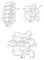
- FIG. 1is a pictorial representation of a lateral view of a portion of a vertebral column.
- FIG. 2is a pictorial representation of a lateral view of a pair of adjacent vertebral bodies defining an intervertebral space.
- FIG. 3is a pictorial representation of an intervertebral prosthetic device disposed between adjacent vertebral bodies.
- FIG. 4is a pictorial representation of a partial cross-sectional view of articulation members of the intervertebral prosthetic device of FIG. 3 .
- FIG. 5is a pictorial representation of a top view of a part of the intervertebral prosthetic device of FIG. 3 on a lower vertebral body.
- FIGS. 6A and 6Bare pictorial representations of an intervertebral prosthetic device disposed between adjacent vertebral bodies.
- FIG. 7is a pictorial representation of a top view of a part of the intervertebral prosthetic device of FIG. 6 .
- FIGS. 8 through 10are pictorial representations of systems for expanding the intervertebral prosthetic devices.
- FIGS. 11 through 15are pictorial representations of exemplary embodiments of intervertebral prosthetic devices.
- FIGS. 16 and 17are pictorial representations of a system for placing the intervertebral prosthetic device.
- FIG. 18is a pictorial representation of articulation members connected by a connecting means.
- FIGS. 19 , 20 A, 20 B, and 21are pictorial representations of an instrument used to implant the intervertebral prosthetic device.
- the present inventionrelates generally to vertebral reconstructive devices, and more particularly, to an articular disc device for implantation.
- an articular disc devicefor implantation.
- FIG. 1shows a lateral view of a portion of a spinal column 10 , illustrating a group of adjacent upper and lower vertebrae V 1 , V 2 , V 3 , V 4 separated by natural intervertebral discs D 1 , D 2 , D 3 .
- the illustration of four vertebraeis only intended as an example. Another example would be a sacrum and one vertebrae.
- the two vertebraeform a spinal motion segment 12 including a lower vertebrae V L and an upper vertebrae V U .
- Some types of disc arthroplastyrequire that some or all of the natural disc that would have been positioned between the two vertebrae V L , V U be removed via a discectomy or a similar surgical procedure. Removal of the diseased or degenerated disc results in the formation of an intervertebral space S between the upper and lower vertebrae V U , V L .
- FIG. 2generally depicts the vertebral joint 12 as a lumbar vertebral joint, it is understood that the devices, systems, and methods of this disclosure may also be applied to all regions of the vertebral column, including the cervical and thoracic regions. Furthermore, the devices, systems, and methods may be used in other regions of the spine, such as, for example, the facet joints. In this disclosure, use of the term intervertebral disc space may also include the facet joints.
- the articular device disclosed hereinmay require a smaller opening and less invasive procedures because the geometry of the prosthetic device is not entirely fixed prior to implantation. Instead, the articular device incorporates at least one expandable member, such a sack or bag, that can be introduced in the intervertebral space S in a small, deflated state. Once in place, the bag may be expanded in-situ to form the articular device.
- the prosthetic devicemay have a smaller profile than conventional discs. Further, because it is not fixed, the profile of the prosthetic device may be readily manipulated if required during insertion.
- a smaller, malleable profilemay allow an operating physician to install the prosthetic device using less invasive installation techniques. For example, instead of being required to install the disc anteriorly, the physician may have the option to install the disc through an alternate direction, such as from a posterior, anterior oblique, or lateral approach to the spine. This may give physicians more options in installation, and may allow the physician to perform less invasive and less distressing procedures.
- the articular device disclosed hereinmay allow a surgeon to manipulate the location of the articular couple within the disc space. For example, a surgeon may be allowed to position the articular couple, even after preparation and placement of the device. Accordingly, the surgeon may more easily place the device with the articular couple at an ideal center of rotation because the articular surface is not attached to rigid endplates.
- FIG. 3shows one exemplary embodiment of a prosthetic device 100 in an intervertebral disc space S.
- the prosthetic device 100includes a top portion 102 and a bottom portion 104 .
- the top portion 102may include a top articulation member 106 and a top expandable member 108 .
- the bottom portion 104may include a bottom articulation member 110 and a bottom expandable member 112 .
- FIG. 4shows a partial cross-sectional view of the articulation members 106 , 110 independent from the expandable members 108 , 112 .
- the top and bottom articulation members 106 , 110may be configured to cooperate together to provide articulation to the prosthetic device 100 and to allow articulation of the upper vertebrae V U relative to the lower vertebrae V L .
- FIGS. 3 and 4show the upper and lower vertebrae V U , V L and the prosthetic device 100 spaced apart.
- the top articulation member 106is intended to cooperate with the bottom articulation member 110 to form an articulating joint.
- the top articulation member 106includes a spherical concave recess forming a socket while the bottom articulation member 110 includes a convex bearing surface forming a ball, together forming a ball and socket joint.
- the top and bottom articulation members 106 , 110may be preformed members made by, for example, forming or molding processes, and may be formed of any rigid material allowing articulation between the respective members.
- the top and bottom articulation members 106 , 110are formed of a biocompatible metal, such as, for example, stainless steel, cobalt chrome, or titanium, among others.
- the top and bottom articulation members 106 , 110may be formed of a biocompatible ceramic material or a polymer material, such as polyethylene and carbon fiber reinforced PEEK that may be optionally combined with metal or ceramic. Other suitable materials also may be used.
- each articulation member 106 , 110includes an articulating surface 114 , 118 , respectively, and an attachment surface 116 , 120 , respectively.
- the articulating surfaces 114 , 118may cooperate to provide the articulation.
- the articulating surfaces 114 , 118may be smooth or polished in order to promote low friction articulation.
- the attachment surfaces 116 , 120 of the articulation members 106 , 110may be configured to engage and attach to the top expandable member 108 and the bottom expandable member 112 , respectively.
- the top expandable member and the bottom expandable membermay be respectively attached to the top and bottom articulation members 106 , 110 .
- This attachmentmay be performed in any suitable manner.
- the articulation members 106 , 110are respectively adhered to the expandable members 108 , 112 using an adhesive.
- the articulation members 106 , 110are adhered to the expandable members 108 , 112 using a woven method where sutures connect the articulation members 106 , 110 and the expandable members 108 , 112 .
- the articulation members 106 , 110may be secured to the respective expandable members 108 , 112 using a tacking or pin system.
- tacksmay be secured to or formed upon the articulation member. The tack may then extend through the expandable member and may be secured inside the expandable member to connect the articulation member and expandable member. Other methods also may be used.
- the top and bottom expandable members 108 , 112may be comprised of biocompatible sacks capable of being filled with a filling material.
- the top and bottom expandable members 108 , 112may be comprised of a woven material as described in U.S. Pat. No. 6,827,743, which is incorporated herein in its entirety by reference.
- the expandable members 108 , 112When in an un-expanded state, the expandable members 108 , 112 may be compliant and malleable allowing deformation and manipulation. Accordingly, they may be rolled or folded to occupy a relatively small volume. Because of this, the prosthetic device 100 may be introduced to the space S of FIG.
- the expandable members 108 , 112may be rolled or folded and fitted through a small cannula that provides access to the vertebral space S from a posterior approach. Accordingly, the prosthetic device 100 may be installed through less invasive surgical methods than when using conventional fixed-geometry prosthetic discs.
- a physicianmay use a trial to determine the proper height of the intervertebral space. Once determined a prosthetic device 100 configured to obtain the desired height may be selected for placement in the intervertebral space. Accordingly, in some embodiments, a number of different sized inflatable members may be provided for selection to allow a proper fit. In some embodiments, expanding the expandable members 108 , 112 may distract the vertebrae. Further, in some of these embodiments, the expandable members may be filled only until the vertebrae are distracted a desired amount.
- the top and bottom portions 102 , 104may be simultaneously placed between the upper and lower vertebrae V U , V L , while in other embodiments, the top and bottom portions 102 , 104 are placed at separate times. When placed together, the top and bottom portions 102 , 104 may be held together during the placement process to limit any relative movement. An implantation tool (not shown) may be implemented for this purpose. In some embodiments, a resorbable ring may be disposed between the top and bottom portions 102 , 104 to locate the portions relative to each other.
- the top and bottom expandable members 108 , 112may be expanded to provide support to the articulation members 106 , 110 .
- the top and bottom expandable members 108 , 112may be designed to expand to a specific shape and height.
- the expandable members 108 , 112may be inelastic so that once the designed shape is obtained, then the shape is maintained.
- the expandable membersmay be designed to expand only to a certain height. In other embodiments, the expandable members may be elastic, allowing the bag to stretch during expansion.
- a filling materialsuch as a biocompatible cement
- a filling materialmay be injected to expand the expandable members 108 , 112 to their pre-established size and geometry.
- the expandable members 108may be at least partially filled with granular materials that may provide some level of rigidity.
- the granular materialsmay include, for example, beads, granules, bone pastes, bone powders, among others.
- FIGS. 6A , 6 B, and 7show one exemplary embodiment of the prosthetic device 100 in an expanded state.
- the expandable members 108 , 112secure the respective articulation members 106 , 110 in a position that allows articulation between the upper and lower vertebrae V U , V L .
- FIG. 6Ashows exaggerated vertebrae spacing to provide clarity to the top and bottom portions 102 , 104 .
- FIG. 6Bshows the vertebrae spaced more conventionally, with the articulation members 106 , 110 engaged to provide articulating motion.
- the top and bottom articulation members 106 , 108form a ball and socket joint.
- the articulation membersalso may form a ball and trough joint, a pea and saucer, or other articulating joint.
- the ball and socket, the ball and trough, and the pea and saucer jointsall allow articulation about any axis providing greater degrees of freedom to a patient.
- the top and bottom articulation members 106 , 110are secured using a pinned joint that forms a hinge allowing articulation in only about a single axis.
- Other types of jointsalso may provide articulation to the vertebrae.
- the expandable members 108 , 112may be expanded with a filling material that initially is at least partially flowable, but that may harden or be compacted to form a substantially rigid and stiff member.
- the filling materialprovides support to the articulation members 106 , 110 and fixes the expandable members 108 , 112 in a specific orientation and geometry.
- FIGS. 8 through 10show exemplary systems for filling the expandable members 108 , 112 .
- FIG. 8shows the expandable members 108 , 112 in a deflated state. Therefore, although the prosthetic device 100 is disposed between the upper and lower vertebrae V U , V L , the upper and lower vertebrae may be compressed together as shown. Accordingly, when the expandable members 108 , 112 are in an unexpanded state, the prosthetic disc 100 , as well as the disc space S may have a height represented by h 1 . Further below, with reference to FIG. 9 , height h 1 will be compared with a height h 2 of the prosthetic disc 100 and the intervertebral disc space where the expandable members 108 , 112 are in an expanded state.
- a syringe 130 having a needle 132may be used to inject the filling material to expand the expandable members 108 , 112 .
- the filling materialmay be in a partially liquid state during injection and may be configured to cure or harden to form a base for the articulation members 106 , 110 .
- a substance injector 134may be used with the expandable members 108 , 112 for simple insertion of the filling material.
- the substance injector 134 in FIG. 9is shown and described as associated only with the expandable member 112 , but a similar injector also may be associated with and used to fill the expandable member 108 .
- the substance injector 134may be preformed and may be attached to and extend from the expandable member 112 . Accordingly, when the expandable members 108 , 112 are placed within the intervertebral space S, the substance injector 134 may provide simple access to a physician who will inject the filling material through the substance injector 134 into one or both of the expandable members 108 , 112 .
- the substance injector 134is integral with the expandable member 112 itself, while in another exemplary embodiment, the substance injector 134 is formed of a material attached to the expandable member 112 . In yet additional exemplary embodiments, the substance injector 134 may be inserted into the expandable member 112 after the expandable member 112 has been located in the intervertebral space S. Once the expandable member 112 is filled, the substance injector 134 may be removed or disposed in a manner to not interfere with articulation of the device 100 or the spinal column. In some exemplary embodiments, including when the substance injector 134 is removable from the expandable member 112 , the substance injector 134 may be configured to be snapped off from the expandable member 112 and removed.
- the substance injector 134may be tied off, cut off, or otherwise removed.
- the substance injector 134is connected with the expandable member 112 and remains in the surgical site with the expandable member 112 .
- the expandable member 108may be configured similar to the expandable member 112 .
- FIG. 9shows the expandable members 108 , 112 in an expanded state.
- the prosthetic disc 100 and the intervertebral spacehave a second height h 2 .
- the second height h 2 of FIG. 9may be greater than the first height h 1 of FIG. 8 because the expanded members 108 , 112 in FIG. 9 contain filling material.
- the first height h 1may be relative smaller than the second height h 2 , as the expandable members 108 , 112 are void of material.
- the muscles and ligaments associated with the spinal columnmay compress the disc space between the upper and lower vertebrae V U , V L after the natural discal tissue is removed.
- the process of filling the expandable members 108 , 112may partially or fully distract the upper and lower vertebrae V U , V L to the desired disc height. Accordingly, the filling process may distract the upper and lower vertebrae V U , V L from the first height h 1 to the second height h 2 .
- FIG. 10shows an exemplary embodiment of a substance injector 134 disposed adjacent the articulation member 110 . Only the bottom portion 104 is shown being filled in FIG. 10 , but it should be understood that the exemplary systems could be used equally with the top portion 102 .
- the substance injector 134may be connected to or removably connected to the articulation member 110 . So doing may allow a physician to use the substance injector 134 as a tool to manipulate the position of the articulation member 110 prior to or during injection of the filling material into the expandable member 112 . Therefore, the physician may be able to orient the articulation member 110 in its proper location in the vertebral space S. Other methods and systems for placing and moving the articulation member 110 into its desired location also may be used.
- the filling material to be injected into the expandable members 108 , 112may be any substance capable of being injected but that will harden to provide sufficient support for the articulation members 106 , 110 and to provide support for the vertebrae itself.
- the filling materialmay be a hardenable material, such as polymethyl-methacrylate (PMMA) cement or a calcium phosphate cement.
- PMMApolymethyl-methacrylate
- the filling materialalso may be an injectable elastomeric or polymeric material.
- the filling materialmay be un-reinforced or may be reinforced with, for example, carbon or glass fibers or some other strengthening structure. If the material injected is an elastomeric or polymeric material, the material may provide cushioning and additional dampening to the device 100 , as well as to the vertebrae.
- radiographic markersmay be introduced into the filling material and the markers may be simultaneously injected with the filling material into the expandable members 108 , 112 .
- radiographic beads or wiresmay be introduced to the filling material. This may simplify later examinations of the prosthetic device 100 by making the device visible when exposed to radiowaves, such as x-rays.
- the filling material introduced into the expandable members 108 , 112may include a radiopaque material, such as, for example, a cement including barium sulfate.
- the filling materialincludes metallic fibers usable as radiopaque markers.
- the expandable members 108 , 112themselves may be formed of and/or may include radiopaque materials.
- the expandable membersmay include wires forming a part of the surface of the expandable member. Therefore, after the surgery, the prosthetic device 100 can be viewed and analyzed, if necessary.
- surgical toolsmay be employed to hold the articulation members 106 , 110 relative to each other in their proper locations while the top and bottom expandable members 108 , 112 , are filled with the filling material. Then, once the filling material is cured, the surgical tool may be removed to allow articulation between the top and bottom articulation members 106 , 110 .
- the articulation members 106 , 110may include additional rigid structures, such as tabs or attachment points that cooperate with the surgical tooling. These structures may provide a grippable surface enabling a physician to manipulate or align the articulation members 106 , 110 and to place the entire upper and lower portions 102 , 104 of the prosthetic device 100 .
- FIGS. 16 and 17show an example of implanting the prosthetic device 100 .
- the device 100may be inserted into an intervertebral disc space through a cannula 160 .
- a connecting meansincluding one or more instruments, such as a first instrument 162 and a second instrument 164 , may connect to the top portion 102 and to the bottom portion 104 , respectively. This allows the top and bottom portions 102 , 104 to separately pass through the cannula 160 so that the cannula can have a minimal diameter.
- the instrumentsmay be manipulated to orient the top and bottom and portions. In one example, the instruments are aligned adjacent each other to place the top and bottom portions.
- the top and bottom portions 102 , 104may be connected and inserted together using a single instrument or more that one instrument, such as the instruments 162 , 164 .
- the instruments 162 , 164may connect at attachment locations formed on the expandable or articulation members or may grip the expandable or articulation members. In one example, the attachment locations may allow the articulation members 106 , 110 to snap onto the instruments 162 , 164 .
- the instruments 162 , 164may attach to each other in a manner to ensure the location of the top portion 102 of the prosthetic device 100 relative to the bottom portion 104 . This may be accomplished by meshing the instruments 162 , 164 , such as by nesting the instruments together, or by configuring them to snap together.
- top and bottom portions 102 , 104are placed simultaneously.
- FIG. 18shows one exemplary embodiment of a connecting means 166 configured to secure the top and bottom articulation members 106 , 110 relative to each other.
- This connecting means 166may be a clip, a connector, or other system configured to hold the top articulation member 106 relative to the bottom articulation member 110 while the expandable members 108 , 112 are filled and manipulated within the disc space.
- the connecting means 166may be a rigid support to secure the top and bottom articulation members 106 , 110 in place. Once the filling material is sufficiently accomplished, and if necessary, any hardening has began, the connecting means may be removed, allowing articulation of the top and bottom articulation members 106 , 110 .
- the connecting means 166may be used as an alternative or in conjunction with instruments that connect in order to properly position the top and bottom portions 102 , 104 . Other systems for securing the top portion relative to the bottom portion also could be used.
- top and bottom portions 102 , 104are held in place until any cement within the expandable members begins to or completely cures. In other examples, the top and bottom portions 102 , 104 are held in place only while the expandable member is filled. Once filled, the top and bottom portions may be manipulated within the disc space to a desired final location.
- the top and bottom portions 102 , 104may be held in place in the disc space by the upper and lower vertebral bodies themselves, such as might occur with a collapsed disc space. As the expandable members 108 , 112 are filled, the height of the disc space may increase. Once the expandable members 108 , 112 are sufficiently filled, the articulation members 106 , 110 are manipulated into their final position.
- the expandable members 108 , 112In addition to connecting to the articulation members 106 , 110 , the expandable members 108 , 112 also connect with end plate surfaces of the upper and lower vertebrae V U , V L .
- Conventional prosthetic discstypically incorporate a flat, top or bottom surface that may not always lie flat or flush against the respective upper or lower vertebrae.
- the prosthetic device 100allows the expandable member 108 , 112 to conform in situ to any surface irregularities, bumps, or high spots of the upper and lower vertebrae V U , V L .
- weight transferred from the vertebrae to the prosthetic device 100can be distributed over a larger area of the vertebrae, thereby reducing chances of health problems, such as resorption cascade, as well as stress risers and other irregularities that may cause pain to a patient.
- FIGS. 11 through 15disclose several exemplary embodiments of expandable members 108 , 112 configured to attach to the upper and lower vertebrae V U , V L . While only the upper expandable member 108 is shown, the lower expandable member 112 may include any of the features described. Preferably, the lower expandable member 112 will have the same features as the upper expandable member 108 .
- the expandable member 108may include an upper surface 140 having pores 141 formed therein.
- the porous upper surface 140may promote bone ingrowth that over time would allow the bone to grow into and hold the expandable member 108 and the prosthetic disc 100 in place.
- the entire expandable member 108may be formed of a material providing the porous structure shown in FIG. 11 .
- the pores 141may be created through a treatment of the upper surface 140 of the expandable member 108 .
- porous materialcould be sewn or sutured to the top of the expandable member 108 , or in a second embodiment, a spray or coating may be applied to the top expandable member 108 .
- the porous surface 140may be a permeable or a semi-permeable structure allowing a portion of the filling material injected to expand the expandable member 108 and to communicate through the upper surface 140 of the expandable member 108 to assist in attachment to the vertebrae.
- the filling material introducible into the expandable member 108is a hardenable adhesive. Accordingly, it may permeate through the upper surface 140 of the expandable member 108 , affixing the expandable member 108 in place against the vertebrae. Alternatively, the bone and connective tissue may grow through the membrane and interact with the filling material.
- FIG. 12shows another embodiment of an expandable member 108 securable to a vertebrae.
- projections 142are preformed onto the upper surface 140 of the expandable member 108 . These projections 142 may engage the vertebrae when the expandable member 108 is filled with the filling material, with the filling material providing the force to drive the projections 142 into the vertebrae.
- the projections 142may be integrally formed with the expandable member 108 of the same material as the expandable member 108 or alternatively, may be secured to the expandable member 108 using an adhesive or cement.
- the projections 142include securing pins that may penetrate the top surface of the expandable member 108 , and may be attached to the interior of the expandable member 108 , thereby securing the projections 142 in place on the expandable member 108 .
- the projections 142are shown as spikes extending from the surface 140 of the expandable member 108 .
- the projections 142could be any shape having, for example, a pointed, tapered, or a flat upper surface spaced from the upper surface of the expandable member 108 , that is configured to engage the vertebrae.
- FIG. 13shows an exemplary expandable member 108 having a coating 144 on its upper surface 140 that may promote integration or bone growth into the expandable member 108 .
- the bone-growth coatingmay be, for example, a hydroxyapatite coating formed of calcium phosphate, a biologic substance such as BMP or other substance, or other material may be applied to the upper surface 140 of the expandable member 108 .
- the top articulation member 106is a trough rather than a ball socket.
- the articulation memberscould have any of a variety different configurations providing articulating motion to the vertebral joint.
- FIG. 14shows yet another exemplary system for attaching the expandable member 108 to the vertebrae V.
- the expandable member 108includes a seam or skirt 146 about its edge.
- stakes 148such as, for example, screws, spikes, or projections, may be used to stake the expandable member 108 against the vertebrae V U .
- the stakes 148may be driven through the skirt 146 about the edge of the expandable member 108 and into the vertebrae V U , securing the expandable member 108 in place against the vertebrae V U .
- FIG. 15shows another exemplary system for attaching the expandable member 108 to the vertebra V U .
- tacks or pins 150may be introduced to an interior of the expandable member 108 through a port 152 .
- the port 152may be associated with the substance injector or other cannula.
- the tacks 150may be driven through the upper surface 140 of the expandable member 108 and into the vertebra V U .
- the tacks 150are inserted through the port 152 into the interior, then rotated 90 degrees to orient the pointed end, and then driven into the vertebra V U .
- Heads 154 on the tacks 150may hold the top surface 140 of the expandable member 108 against the vertebra V U . Once those tacks 150 are in place, filling the expandable member 108 with the filling material may apply pressure on the heads 154 , driving the tacks 150 further into the vertebra and securing the expandable member 108 against the vertebra V U .
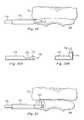
- FIGS. 19 , 20 A, 20 B, and 21show one example of introducing tacks 150 into the expandable member 108 to attach the expandable member to a vertebra as shown in FIG. 15 .
- an insertion tool 70is introduced through an insertion tube 72 into the expandable member 108 .
- the insertion tool 70includes a distal end 174 configured to attached to the tack 150 and a proximal end (not shown) configured to be manipulated by a surgeon.
- the insertion tool 70may be configured with a rotation means 176 , such as, for example, a hinge, a compliant member, or a flexible member, that allows the distal end 174 to rotate the tack 150 toward the vertebral endplate. In the example shown, the distal end is configured to rotate 90 degrees.
- a rotation means 176such as, for example, a hinge, a compliant member, or a flexible member, that allows the distal end 174 to rotate the tack 150 toward the vertebral endplate. In the example shown, the distal end is configured to rotate 90 degrees.
- FIG. 20Ashows the insertion tool 170 and tack 150 in a position for insertion through the insertion tube 172
- FIG. 20Bshows the insertion tool 170 and tack 150 rotated to allow the tack 150 to be driven into the vertebra
- FIG. 21shows the manipulated tack 150 and insertion tool 170 within the inflatable member 108 . Once placed, the articulation members may still be manipulated within the disc space so that they are located to provide an ideal center of rotation.
- kitsmay include, for example, the prosthetic device 100 with its articulation members 106 , 108 and its expandable members 110 , 112 .
- the filling material, as described above,also may be part of the kit. Other combinations could also be used.
- the prosthetic device 100 described hereinmay be placed and fitted into an intervertebral space S in an un-expanded state.
- a physicianmay form an introductory cavity or access to the damaged or degenerated disc.
- the physicianmay remove all or part of the disc.
- the physicianmay then introduce the top and bottom portions 102 , 104 of the prosthetic device 100 to the disc space, either together or one at a time.
- the upper and lower portions 102 , 104may be introduced in an un-expanded state, the upper and lower portions 102 , 104 may have a smaller profile and geometry than conventional prosthetic discs. Accordingly, introducing the upper and lower portions 102 , 104 may be performed from not only an anterior direction, but also from other directions, such as a posterior or lateral direction. In one exemplary embodiment, the expandable members 108 , 112 of the upper and lower portions 102 , 104 are rolled to form a small profile during introduction.
- the expandable members 108 , 112may be adjusted and placed so that the attached articulation members 106 , 110 are disposed in a proper position. Adjusting the expandable members 108 , 112 may include unrolling the expandable members 108 , 112 and aligning the articulation members 106 , 110 by manipulating the attached substance injector 134 . In some exemplary embodiments, the expandable member may be pinned or staked to the adjacent vertebrae.
- a filling materialmay be introduced to the expandable members 108 , 112 , expanding them to their pre-established size and shape.
- the articulation members 106 , 110may be held in place by a tool while the filling material is introduced.
- expanding the expandable members 108 , 112may distract the vertebrae a desired distance to provide the properly sized disc space.
- expanding the expandable members 108 , 112may drive projections or pins or other attachment systems into contact with the vertebrae.
- the substance injectormay be removed from the expandable member.
- the smaller profile and manipulatable profile of the prosthetic device 100may allow the device to be insertable from a number of different directions. Accordingly, the surgical process may be less invasive and less complex. This may reduce recovery time and may simplify subsequent surgeries, should they become necessary.
Landscapes
- Health & Medical Sciences (AREA)
- Engineering & Computer Science (AREA)
- Biomedical Technology (AREA)
- Orthopedic Medicine & Surgery (AREA)
- Transplantation (AREA)
- Life Sciences & Earth Sciences (AREA)
- General Health & Medical Sciences (AREA)
- Cardiology (AREA)
- Heart & Thoracic Surgery (AREA)
- Vascular Medicine (AREA)
- Neurology (AREA)
- Animal Behavior & Ethology (AREA)
- Oral & Maxillofacial Surgery (AREA)
- Public Health (AREA)
- Veterinary Medicine (AREA)
- Physical Education & Sports Medicine (AREA)
- Chemical & Material Sciences (AREA)
- Dispersion Chemistry (AREA)
- Manufacturing & Machinery (AREA)
- Prostheses (AREA)
Abstract
Description
Claims (14)
Priority Applications (7)
| Application Number | Priority Date | Filing Date | Title |
|---|---|---|---|
| US11/362,998US7918889B2 (en) | 2006-02-27 | 2006-02-27 | Expandable spinal prosthetic devices and associated methods |
| PCT/US2007/062372WO2007100996A2 (en) | 2006-02-27 | 2007-02-19 | Expandable articulated prosthetic device for spinal arthroplasty |
| KR1020087023569AKR20080098674A (en) | 2006-02-27 | 2007-02-19 | Artificial device for spinal arthroplasty |
| JP2008557447AJP2009528142A (en) | 2006-02-27 | 2007-02-19 | Prosthesis for spinal arthroplasty |
| CNA2007800067052ACN101394812A (en) | 2006-02-27 | 2007-02-19 | Prosthetic device for spinal joint arthroplasty |
| AU2007220895AAU2007220895A1 (en) | 2006-02-27 | 2007-02-19 | Expandable articulated prosthetic device for spinal arthroplasty |
| EP07757168AEP1991174A2 (en) | 2006-02-27 | 2007-02-19 | Expandable articulated prosthetic device for spinal arthroplasty |
Applications Claiming Priority (1)
| Application Number | Priority Date | Filing Date | Title |
|---|---|---|---|
| US11/362,998US7918889B2 (en) | 2006-02-27 | 2006-02-27 | Expandable spinal prosthetic devices and associated methods |
Publications (2)
| Publication Number | Publication Date |
|---|---|
| US20070203579A1 US20070203579A1 (en) | 2007-08-30 |
| US7918889B2true US7918889B2 (en) | 2011-04-05 |
Family
ID=38229306
Family Applications (1)
| Application Number | Title | Priority Date | Filing Date |
|---|---|---|---|
| US11/362,998Expired - Fee RelatedUS7918889B2 (en) | 2006-02-27 | 2006-02-27 | Expandable spinal prosthetic devices and associated methods |
Country Status (7)
| Country | Link |
|---|---|
| US (1) | US7918889B2 (en) |
| EP (1) | EP1991174A2 (en) |
| JP (1) | JP2009528142A (en) |
| KR (1) | KR20080098674A (en) |
| CN (1) | CN101394812A (en) |
| AU (1) | AU2007220895A1 (en) |
| WO (1) | WO2007100996A2 (en) |
Cited By (2)
| Publication number | Priority date | Publication date | Assignee | Title |
|---|---|---|---|---|
| US8906095B2 (en) | 2011-03-11 | 2014-12-09 | FBC Device ApS | Spinal implant, instrument for preparation and method of use |
| US9622876B1 (en) | 2012-04-25 | 2017-04-18 | Theken Spine, Llc | Expandable support device and method of use |
Families Citing this family (7)
| Publication number | Priority date | Publication date | Assignee | Title |
|---|---|---|---|---|
| CA2363254C (en) | 1999-03-07 | 2009-05-05 | Discure Ltd. | Method and apparatus for computerized surgery |
| US20090299478A1 (en)* | 2008-06-03 | 2009-12-03 | Warsaw Orthopedic, Inc. | Lordotic Implant for Posterior Approach |
| JP4900848B2 (en)* | 2009-01-26 | 2012-03-21 | 宏美 林 | Artificial joint |
| EP2582331B1 (en) | 2010-06-18 | 2017-09-13 | Synthes GmbH | Spine disc replacement with compliant articulating core |
| US20120109306A1 (en)* | 2010-10-28 | 2012-05-03 | Warsaw Orthopedic, Inc. | Spinal implant |
| US9308123B2 (en)* | 2013-09-16 | 2016-04-12 | Neuraxis, Llc | Methods and devices for applying localized thermal therapy |
| US8911486B1 (en) | 2013-09-16 | 2014-12-16 | Neuraxis, Llc | Implantable devices for thermal therapy and related methods |
Citations (82)
| Publication number | Priority date | Publication date | Assignee | Title |
|---|---|---|---|---|
| US2182673A (en)* | 1938-03-16 | 1939-12-05 | Magnano Everino | Screw driver |
| US3875595A (en) | 1974-04-15 | 1975-04-08 | Edward C Froning | Intervertebral disc prosthesis and instruments for locating same |
| US4772287A (en) | 1987-08-20 | 1988-09-20 | Cedar Surgical, Inc. | Prosthetic disc and method of implanting |
| US4863477A (en) | 1987-05-12 | 1989-09-05 | Monson Gary L | Synthetic intervertebral disc prosthesis |
| US5047055A (en) | 1990-12-21 | 1991-09-10 | Pfizer Hospital Products Group, Inc. | Hydrogel intervertebral disc nucleus |
| US5146933A (en) | 1991-09-20 | 1992-09-15 | Dow Corning Wright Corporation | Implantable prosthetic device and tethered inflation valve for volume |
| US5171280A (en) | 1990-04-20 | 1992-12-15 | Sulzer Brothers Limited | Intervertebral prosthesis |
| US5334626A (en)* | 1992-07-28 | 1994-08-02 | Zimmer, Inc. | Bone cement composition and method of manufacture |
| US5344459A (en) | 1991-12-03 | 1994-09-06 | Swartz Stephen J | Arthroscopically implantable prosthesis |
| US5425773A (en)* | 1992-01-06 | 1995-06-20 | Danek Medical, Inc. | Intervertebral disk arthroplasty device |
| US5522898A (en) | 1993-09-16 | 1996-06-04 | Howmedica Inc. | Dehydration of hydrogels |
| US5549679A (en) | 1994-05-20 | 1996-08-27 | Kuslich; Stephen D. | Expandable fabric implant for stabilizing the spinal motion segment |
| US5562736A (en) | 1994-10-17 | 1996-10-08 | Raymedica, Inc. | Method for surgical implantation of a prosthetic spinal disc nucleus |
| US5645597A (en) | 1995-12-29 | 1997-07-08 | Krapiva; Pavel I. | Disc replacement method and apparatus |
| US5705780A (en) | 1995-06-02 | 1998-01-06 | Howmedica Inc. | Dehydration of hydrogels |
| US5755797A (en) | 1993-04-21 | 1998-05-26 | Sulzer Medizinaltechnik Ag | Intervertebral prosthesis and a process for implanting such a prosthesis |
| US5824093A (en) | 1994-10-17 | 1998-10-20 | Raymedica, Inc. | Prosthetic spinal disc nucleus |
| WO1998046169A1 (en) | 1997-04-15 | 1998-10-22 | Limber Ltd. | Bone-growth promoting implant |
| US5888220A (en) | 1994-05-06 | 1999-03-30 | Advanced Bio Surfaces, Inc. | Articulating joint repair |
| US5919235A (en) | 1995-11-08 | 1999-07-06 | Sulzer Orthopaedie Ag | Intervertebral prosthesis |
| US5928284A (en) | 1998-07-09 | 1999-07-27 | Mehdizadeh; Hamid M. | Disc replacement prosthesis |
| US5976189A (en) | 1997-03-26 | 1999-11-02 | Waldemar Link (Gmbh & Co) | Assembly comprising a joint endoprosthesis |
| US6022376A (en)* | 1997-06-06 | 2000-02-08 | Raymedica, Inc. | Percutaneous prosthetic spinal disc nucleus and method of manufacture |
| US6140452A (en) | 1994-05-06 | 2000-10-31 | Advanced Bio Surfaces, Inc. | Biomaterial for in situ tissue repair |
| US6146422A (en) | 1999-01-25 | 2000-11-14 | Lawson; Kevin Jon | Prosthetic nucleus replacement for surgical reconstruction of intervertebral discs and treatment method |
| US6183518B1 (en) | 1999-02-22 | 2001-02-06 | Anthony C. Ross | Method of replacing nucleus pulposus and repairing the intervertebral disk |
| US6206921B1 (en) | 1999-02-22 | 2001-03-27 | Peter A. Guagliano | Method of replacing nucleus pulposus and repairing the intervertebral disk |
| US6231609B1 (en) | 1998-07-09 | 2001-05-15 | Hamid M. Mehdizadeh | Disc replacement prosthesis |
| US6248131B1 (en) | 1994-05-06 | 2001-06-19 | Advanced Bio Surfaces, Inc. | Articulating joint repair |
| US20010004710A1 (en) | 1994-05-06 | 2001-06-21 | Jeffrey C. Felt | Mold apparatus and kit for in situ tissue repair |
| US6264695B1 (en) | 1999-09-30 | 2001-07-24 | Replication Medical, Inc. | Spinal nucleus implant |
| US20010049527A1 (en) | 2000-02-16 | 2001-12-06 | Cragg Andrew H. | Methods and apparatus for performing therapeutic procedures in the spine |
| US20020016583A1 (en) | 2000-02-16 | 2002-02-07 | Cragg Andrew H. | Methods of performing procedures in the spine |
| US20020026195A1 (en) | 2000-04-07 | 2002-02-28 | Kyphon Inc. | Insertion devices and method of use |
| US6375682B1 (en) | 2001-08-06 | 2002-04-23 | Lewis W. Fleischmann | Collapsible, rotatable and expandable spinal hydraulic prosthetic device |
| US20020049498A1 (en) | 2000-10-24 | 2002-04-25 | Yuksel K. Umit | In situ bioprosthetic filler and methods, particularly for the in situ formation of vertebral disc bioprosthetics |
| US20020059001A1 (en) | 2000-11-07 | 2002-05-16 | Yuksel K. Umit | Expandable foam-like biomaterials and methods |
| US6402784B1 (en) | 1997-07-10 | 2002-06-11 | Aberdeen Orthopaedic Developments Limited | Intervertebral disc nucleus prosthesis |
| US6402750B1 (en) | 2000-04-04 | 2002-06-11 | Spinlabs, Llc | Devices and methods for the treatment of spinal disorders |
| US6419704B1 (en) | 1999-10-08 | 2002-07-16 | Bret Ferree | Artificial intervertebral disc replacement methods and apparatus |
| US20020107573A1 (en) | 1999-03-07 | 2002-08-08 | Discure Ltd. | Method and apparatus for computerized surgery |
| US6482234B1 (en) | 2000-04-26 | 2002-11-19 | Pearl Technology Holdings, Llc | Prosthetic spinal disc |
| US20020177866A1 (en) | 2001-04-19 | 2002-11-28 | Stuart Weikel | Inflatable device and method for reducing fractures in bone and in treating the spine |
| US6517580B1 (en)* | 2000-03-03 | 2003-02-11 | Scient'x Societe A Responsabilite Limited | Disk prosthesis for cervical vertebrae |
| US20030040802A1 (en)* | 2001-07-16 | 2003-02-27 | Errico Joseph P. | Artificial intervertebral disc having limited rotation using a captured ball and socket joint with a solid ball and compression locking post |
| US20030074075A1 (en) | 2001-08-27 | 2003-04-17 | Thomas James C. | Expandable implant for partial disc replacement and reinforcement of a disc partially removed in a discectomy and for reduction and maintenance of alignment of cancellous bone fractures and methods and apparatuses for same |
| US20030074076A1 (en) | 1999-10-08 | 2003-04-17 | Ferree Bret A. | Artificial intervertebral disc replacements with endplates |
| US20030083642A1 (en) | 2001-11-01 | 2003-05-01 | Boyd Lawrence M. | Devices and methods for the restoration of a spinal disc |
| US20030135278A1 (en)* | 2002-01-17 | 2003-07-17 | Concept Matrix, Llc | Intervertebral disk prosthesis |
| US6602291B1 (en) | 1999-04-05 | 2003-08-05 | Raymedica, Inc. | Prosthetic spinal disc nucleus having a shape change characteristic |
| US6645248B2 (en) | 2001-08-24 | 2003-11-11 | Sulzer Orthopedics Ltd. | Artificial intervertebral disc |
| US20040024463A1 (en) | 2001-08-27 | 2004-02-05 | Thomas James C. | Expandable implant for partial disc replacement and reinforcement of a disc partially removed in a discectomy and for reduction and maintenance of alignment of cancellous bone fractures and methods and apparatuses for same |
| US6692495B1 (en) | 1999-10-14 | 2004-02-17 | Fred Zacouto | Vertebral fixator and articulation |
| US20040054413A1 (en) | 2002-09-16 | 2004-03-18 | Howmedica Osteonics Corp. | Radiovisible hydrogel intervertebral disc nucleus |
| US20040073308A1 (en) | 2000-07-21 | 2004-04-15 | Spineology, Inc. | Expandable porous mesh bag device and methods of use for reduction, filling, fixation, and supporting of bone |
| US6733533B1 (en) | 2002-11-19 | 2004-05-11 | Zimmer Technology, Inc. | Artificial spinal disc |
| US20040093087A1 (en) | 2002-11-05 | 2004-05-13 | Ferree Bret A. | Fluid-filled artificial disc replacement (ADR) |
| US20040102774A1 (en) | 2002-11-21 | 2004-05-27 | Trieu Hai H. | Systems and techniques for intravertebral spinal stabilization with expandable devices |
| US20040133280A1 (en) | 2002-11-21 | 2004-07-08 | Trieu Hai H. | Systems and techniques for interbody spinal stabilization with expandable devices |
| US6783546B2 (en) | 1999-09-13 | 2004-08-31 | Keraplast Technologies, Ltd. | Implantable prosthetic or tissue expanding device |
| US20040186576A1 (en) | 2003-03-20 | 2004-09-23 | Spineco, Inc., An Ohio Corporation | Expandable spherical spinal implant |
| US20040186471A1 (en) | 2002-12-07 | 2004-09-23 | Sdgi Holdings, Inc. | Method and apparatus for intervertebral disc expansion |
| US20040193273A1 (en) | 2003-03-31 | 2004-09-30 | Shih-Shing Huang | Vividly simulated prosthetic intervertebral disc |
| US20040210297A1 (en) | 2003-04-18 | 2004-10-21 | A-Spine Holding Group Corp. | Filling device and system for treating a deformed or diseased spine |
| US20040215342A1 (en) | 2003-04-23 | 2004-10-28 | Loubert Suddaby | Inflatable intervertebral disc replacement prosthesis |
| US20040220296A1 (en) | 2003-04-30 | 2004-11-04 | Lowman Anthony M. | Thermogelling polymer blends for biomaterial applications |
| US20040220582A1 (en)* | 2001-01-12 | 2004-11-04 | Arnold Keller | Surgical instrument for inserting an intervertebral endoprosthesis |
| US6827743B2 (en) | 2001-02-28 | 2004-12-07 | Sdgi Holdings, Inc. | Woven orthopedic implants |
| US20050049707A1 (en) | 2003-08-29 | 2005-03-03 | Ferree Bret A. | Cemented artificial disc replacements |
| US20050060036A1 (en) | 2003-05-21 | 2005-03-17 | Robert Schultz | Spinal column implant |
| US20050090901A1 (en) | 2001-12-05 | 2005-04-28 | Armin Studer | Intervertebral disk prosthesis or nucleus replacement prosthesis |
| US20050143749A1 (en)* | 2003-12-31 | 2005-06-30 | Depuy Spine, Inc. | Inserter instrument and implant clip |
| US20050187631A1 (en)* | 2004-01-27 | 2005-08-25 | Sdgi Holdings, Inc. | Prosthetic device |
| US20050197702A1 (en) | 2002-08-15 | 2005-09-08 | Coppes Justin K. | Intervertebral disc implant |
| US20050209601A1 (en) | 2004-03-22 | 2005-09-22 | Disc Dynamics, Inc. | Multi-stage biomaterial injection system for spinal implants |
| US6958077B2 (en) | 2003-07-29 | 2005-10-25 | Loubert Suddaby | Inflatable nuclear prosthesis |
| WO2005107654A1 (en) | 2004-04-22 | 2005-11-17 | Sdgi Holdings, Inc. | Prosthetic intervertebral disc |
| US20060015183A1 (en) | 2004-07-09 | 2006-01-19 | Pioneer Laboratories, Inc. | Skeletal reconstruction device |
| US20060084988A1 (en)* | 2004-10-20 | 2006-04-20 | The Board Of Trustees Of The Leland Stanford Junior University | Systems and methods for posterior dynamic stabilization of the spine |
| US7235104B2 (en)* | 2004-11-19 | 2007-06-26 | Depuy Spine, Inc. | Method of protecting and lubricating bearing surfaces of an artificial disc |
| US20070150059A1 (en)* | 2005-12-22 | 2007-06-28 | Depuy Spine, Inc. | Methods and devices for intervertebral augmentation using injectable formulations and enclosures |
| US7563286B2 (en)* | 2002-08-15 | 2009-07-21 | Synthes Usa, Llc | Controlled artificial intervertebral disc implant |
- 2006
- 2006-02-27USUS11/362,998patent/US7918889B2/ennot_activeExpired - Fee Related
- 2007
- 2007-02-19EPEP07757168Apatent/EP1991174A2/ennot_activeWithdrawn
- 2007-02-19AUAU2007220895Apatent/AU2007220895A1/ennot_activeAbandoned
- 2007-02-19KRKR1020087023569Apatent/KR20080098674A/ennot_activeCeased
- 2007-02-19JPJP2008557447Apatent/JP2009528142A/enactivePending
- 2007-02-19CNCNA2007800067052Apatent/CN101394812A/enactivePending
- 2007-02-19WOPCT/US2007/062372patent/WO2007100996A2/enactiveApplication Filing
Patent Citations (90)
| Publication number | Priority date | Publication date | Assignee | Title |
|---|---|---|---|---|
| US2182673A (en)* | 1938-03-16 | 1939-12-05 | Magnano Everino | Screw driver |
| US3875595A (en) | 1974-04-15 | 1975-04-08 | Edward C Froning | Intervertebral disc prosthesis and instruments for locating same |
| US4863477A (en) | 1987-05-12 | 1989-09-05 | Monson Gary L | Synthetic intervertebral disc prosthesis |
| US4772287A (en) | 1987-08-20 | 1988-09-20 | Cedar Surgical, Inc. | Prosthetic disc and method of implanting |
| US4904260A (en) | 1987-08-20 | 1990-02-27 | Cedar Surgical, Inc. | Prosthetic disc containing therapeutic material |
| US5171280A (en) | 1990-04-20 | 1992-12-15 | Sulzer Brothers Limited | Intervertebral prosthesis |
| US5047055A (en) | 1990-12-21 | 1991-09-10 | Pfizer Hospital Products Group, Inc. | Hydrogel intervertebral disc nucleus |
| US5146933A (en) | 1991-09-20 | 1992-09-15 | Dow Corning Wright Corporation | Implantable prosthetic device and tethered inflation valve for volume |
| US5344459A (en) | 1991-12-03 | 1994-09-06 | Swartz Stephen J | Arthroscopically implantable prosthesis |
| US5425773A (en)* | 1992-01-06 | 1995-06-20 | Danek Medical, Inc. | Intervertebral disk arthroplasty device |
| US5334626A (en)* | 1992-07-28 | 1994-08-02 | Zimmer, Inc. | Bone cement composition and method of manufacture |
| US5755797A (en) | 1993-04-21 | 1998-05-26 | Sulzer Medizinaltechnik Ag | Intervertebral prosthesis and a process for implanting such a prosthesis |
| US5522898A (en) | 1993-09-16 | 1996-06-04 | Howmedica Inc. | Dehydration of hydrogels |
| US5888220A (en) | 1994-05-06 | 1999-03-30 | Advanced Bio Surfaces, Inc. | Articulating joint repair |
| US20010004710A1 (en) | 1994-05-06 | 2001-06-21 | Jeffrey C. Felt | Mold apparatus and kit for in situ tissue repair |
| US6306177B1 (en) | 1994-05-06 | 2001-10-23 | Advanced Bio Surfaces, Inc. | Biomaterial system for in situ tissue repair |
| US6140452A (en) | 1994-05-06 | 2000-10-31 | Advanced Bio Surfaces, Inc. | Biomaterial for in situ tissue repair |
| US6248131B1 (en) | 1994-05-06 | 2001-06-19 | Advanced Bio Surfaces, Inc. | Articulating joint repair |
| US5571189A (en) | 1994-05-20 | 1996-11-05 | Kuslich; Stephen D. | Expandable fabric implant for stabilizing the spinal motion segment |
| US5549679A (en) | 1994-05-20 | 1996-08-27 | Kuslich; Stephen D. | Expandable fabric implant for stabilizing the spinal motion segment |
| US5824093A (en) | 1994-10-17 | 1998-10-20 | Raymedica, Inc. | Prosthetic spinal disc nucleus |
| US5562736A (en) | 1994-10-17 | 1996-10-08 | Raymedica, Inc. | Method for surgical implantation of a prosthetic spinal disc nucleus |
| US5705780A (en) | 1995-06-02 | 1998-01-06 | Howmedica Inc. | Dehydration of hydrogels |
| US5919235A (en) | 1995-11-08 | 1999-07-06 | Sulzer Orthopaedie Ag | Intervertebral prosthesis |
| US6610094B2 (en) | 1995-11-08 | 2003-08-26 | Sulzer Orthopaedie Ag | Intervertebral prosthesis |
| US6165218A (en) | 1995-11-08 | 2000-12-26 | Sulzer Orthopaedie Ag | Intervertebral prosthesis |
| US5645597A (en) | 1995-12-29 | 1997-07-08 | Krapiva; Pavel I. | Disc replacement method and apparatus |
| US5976189A (en) | 1997-03-26 | 1999-11-02 | Waldemar Link (Gmbh & Co) | Assembly comprising a joint endoprosthesis |
| WO1998046169A1 (en) | 1997-04-15 | 1998-10-22 | Limber Ltd. | Bone-growth promoting implant |
| US6022376A (en)* | 1997-06-06 | 2000-02-08 | Raymedica, Inc. | Percutaneous prosthetic spinal disc nucleus and method of manufacture |
| US6402784B1 (en) | 1997-07-10 | 2002-06-11 | Aberdeen Orthopaedic Developments Limited | Intervertebral disc nucleus prosthesis |
| US6231609B1 (en) | 1998-07-09 | 2001-05-15 | Hamid M. Mehdizadeh | Disc replacement prosthesis |
| US5928284A (en) | 1998-07-09 | 1999-07-27 | Mehdizadeh; Hamid M. | Disc replacement prosthesis |
| US6146422A (en) | 1999-01-25 | 2000-11-14 | Lawson; Kevin Jon | Prosthetic nucleus replacement for surgical reconstruction of intervertebral discs and treatment method |
| US6206921B1 (en) | 1999-02-22 | 2001-03-27 | Peter A. Guagliano | Method of replacing nucleus pulposus and repairing the intervertebral disk |
| US6183518B1 (en) | 1999-02-22 | 2001-02-06 | Anthony C. Ross | Method of replacing nucleus pulposus and repairing the intervertebral disk |
| US20020107573A1 (en) | 1999-03-07 | 2002-08-08 | Discure Ltd. | Method and apparatus for computerized surgery |
| US6602291B1 (en) | 1999-04-05 | 2003-08-05 | Raymedica, Inc. | Prosthetic spinal disc nucleus having a shape change characteristic |
| US6783546B2 (en) | 1999-09-13 | 2004-08-31 | Keraplast Technologies, Ltd. | Implantable prosthetic or tissue expanding device |
| US6264695B1 (en) | 1999-09-30 | 2001-07-24 | Replication Medical, Inc. | Spinal nucleus implant |
| US6419704B1 (en) | 1999-10-08 | 2002-07-16 | Bret Ferree | Artificial intervertebral disc replacement methods and apparatus |
| US20030074076A1 (en) | 1999-10-08 | 2003-04-17 | Ferree Bret A. | Artificial intervertebral disc replacements with endplates |
| US6692495B1 (en) | 1999-10-14 | 2004-02-17 | Fred Zacouto | Vertebral fixator and articulation |
| US20010049527A1 (en) | 2000-02-16 | 2001-12-06 | Cragg Andrew H. | Methods and apparatus for performing therapeutic procedures in the spine |
| US20020016583A1 (en) | 2000-02-16 | 2002-02-07 | Cragg Andrew H. | Methods of performing procedures in the spine |
| US6517580B1 (en)* | 2000-03-03 | 2003-02-11 | Scient'x Societe A Responsabilite Limited | Disk prosthesis for cervical vertebrae |
| US6402750B1 (en) | 2000-04-04 | 2002-06-11 | Spinlabs, Llc | Devices and methods for the treatment of spinal disorders |
| US6835205B2 (en) | 2000-04-04 | 2004-12-28 | Spinalabs, Llc | Devices and methods for the treatment of spinal disorders |
| US20020026195A1 (en) | 2000-04-07 | 2002-02-28 | Kyphon Inc. | Insertion devices and method of use |
| US6482234B1 (en) | 2000-04-26 | 2002-11-19 | Pearl Technology Holdings, Llc | Prosthetic spinal disc |
| US20040073308A1 (en) | 2000-07-21 | 2004-04-15 | Spineology, Inc. | Expandable porous mesh bag device and methods of use for reduction, filling, fixation, and supporting of bone |
| US20020049498A1 (en) | 2000-10-24 | 2002-04-25 | Yuksel K. Umit | In situ bioprosthetic filler and methods, particularly for the in situ formation of vertebral disc bioprosthetics |
| US20020059001A1 (en) | 2000-11-07 | 2002-05-16 | Yuksel K. Umit | Expandable foam-like biomaterials and methods |
| US20040220582A1 (en)* | 2001-01-12 | 2004-11-04 | Arnold Keller | Surgical instrument for inserting an intervertebral endoprosthesis |
| US6827743B2 (en) | 2001-02-28 | 2004-12-07 | Sdgi Holdings, Inc. | Woven orthopedic implants |
| US20020177866A1 (en) | 2001-04-19 | 2002-11-28 | Stuart Weikel | Inflatable device and method for reducing fractures in bone and in treating the spine |
| US20030040802A1 (en)* | 2001-07-16 | 2003-02-27 | Errico Joseph P. | Artificial intervertebral disc having limited rotation using a captured ball and socket joint with a solid ball and compression locking post |
| US6375682B1 (en) | 2001-08-06 | 2002-04-23 | Lewis W. Fleischmann | Collapsible, rotatable and expandable spinal hydraulic prosthetic device |
| US6645248B2 (en) | 2001-08-24 | 2003-11-11 | Sulzer Orthopedics Ltd. | Artificial intervertebral disc |
| US20040024463A1 (en) | 2001-08-27 | 2004-02-05 | Thomas James C. | Expandable implant for partial disc replacement and reinforcement of a disc partially removed in a discectomy and for reduction and maintenance of alignment of cancellous bone fractures and methods and apparatuses for same |
| US20030074075A1 (en) | 2001-08-27 | 2003-04-17 | Thomas James C. | Expandable implant for partial disc replacement and reinforcement of a disc partially removed in a discectomy and for reduction and maintenance of alignment of cancellous bone fractures and methods and apparatuses for same |
| US20030083642A1 (en) | 2001-11-01 | 2003-05-01 | Boyd Lawrence M. | Devices and methods for the restoration of a spinal disc |
| US20050090901A1 (en) | 2001-12-05 | 2005-04-28 | Armin Studer | Intervertebral disk prosthesis or nucleus replacement prosthesis |
| US20030135278A1 (en)* | 2002-01-17 | 2003-07-17 | Concept Matrix, Llc | Intervertebral disk prosthesis |
| US20050197702A1 (en) | 2002-08-15 | 2005-09-08 | Coppes Justin K. | Intervertebral disc implant |
| US7563286B2 (en)* | 2002-08-15 | 2009-07-21 | Synthes Usa, Llc | Controlled artificial intervertebral disc implant |
| US20040054413A1 (en) | 2002-09-16 | 2004-03-18 | Howmedica Osteonics Corp. | Radiovisible hydrogel intervertebral disc nucleus |
| US20040093087A1 (en) | 2002-11-05 | 2004-05-13 | Ferree Bret A. | Fluid-filled artificial disc replacement (ADR) |
| US6733533B1 (en) | 2002-11-19 | 2004-05-11 | Zimmer Technology, Inc. | Artificial spinal disc |
| US20040133280A1 (en) | 2002-11-21 | 2004-07-08 | Trieu Hai H. | Systems and techniques for interbody spinal stabilization with expandable devices |
| US20040102774A1 (en) | 2002-11-21 | 2004-05-27 | Trieu Hai H. | Systems and techniques for intravertebral spinal stabilization with expandable devices |
| US20040186471A1 (en) | 2002-12-07 | 2004-09-23 | Sdgi Holdings, Inc. | Method and apparatus for intervertebral disc expansion |
| US20040186576A1 (en) | 2003-03-20 | 2004-09-23 | Spineco, Inc., An Ohio Corporation | Expandable spherical spinal implant |
| US6893465B2 (en) | 2003-03-31 | 2005-05-17 | Shi, Tain-Yew | Vividly simulated prosthetic intervertebral disc |
| US20040193273A1 (en) | 2003-03-31 | 2004-09-30 | Shih-Shing Huang | Vividly simulated prosthetic intervertebral disc |
| US20040210297A1 (en) | 2003-04-18 | 2004-10-21 | A-Spine Holding Group Corp. | Filling device and system for treating a deformed or diseased spine |
| US20040215342A1 (en) | 2003-04-23 | 2004-10-28 | Loubert Suddaby | Inflatable intervertebral disc replacement prosthesis |
| US20040220296A1 (en) | 2003-04-30 | 2004-11-04 | Lowman Anthony M. | Thermogelling polymer blends for biomaterial applications |
| US20050060036A1 (en) | 2003-05-21 | 2005-03-17 | Robert Schultz | Spinal column implant |
| US6958077B2 (en) | 2003-07-29 | 2005-10-25 | Loubert Suddaby | Inflatable nuclear prosthesis |
| US20050049707A1 (en) | 2003-08-29 | 2005-03-03 | Ferree Bret A. | Cemented artificial disc replacements |
| US20050143749A1 (en)* | 2003-12-31 | 2005-06-30 | Depuy Spine, Inc. | Inserter instrument and implant clip |
| US20050187631A1 (en)* | 2004-01-27 | 2005-08-25 | Sdgi Holdings, Inc. | Prosthetic device |
| US20050209601A1 (en) | 2004-03-22 | 2005-09-22 | Disc Dynamics, Inc. | Multi-stage biomaterial injection system for spinal implants |
| US20050209602A1 (en) | 2004-03-22 | 2005-09-22 | Disc Dynamics, Inc. | Multi-stage biomaterial injection system for spinal implants |
| WO2005107654A1 (en) | 2004-04-22 | 2005-11-17 | Sdgi Holdings, Inc. | Prosthetic intervertebral disc |
| US20060015183A1 (en) | 2004-07-09 | 2006-01-19 | Pioneer Laboratories, Inc. | Skeletal reconstruction device |
| US20060084988A1 (en)* | 2004-10-20 | 2006-04-20 | The Board Of Trustees Of The Leland Stanford Junior University | Systems and methods for posterior dynamic stabilization of the spine |
| US7235104B2 (en)* | 2004-11-19 | 2007-06-26 | Depuy Spine, Inc. | Method of protecting and lubricating bearing surfaces of an artificial disc |
| US20070150059A1 (en)* | 2005-12-22 | 2007-06-28 | Depuy Spine, Inc. | Methods and devices for intervertebral augmentation using injectable formulations and enclosures |
Non-Patent Citations (1)
| Title |
|---|
| European Patent Office, International Searching Authority,Notification of Transmittal of the International Search Report and the Written Opinion of the International Searching Authority or the Declaration, International Application No. PCT/US2007/062372, Jul. 27, 2007, 7 pages. |
Cited By (5)
| Publication number | Priority date | Publication date | Assignee | Title |
|---|---|---|---|---|
| US8906095B2 (en) | 2011-03-11 | 2014-12-09 | FBC Device ApS | Spinal implant, instrument for preparation and method of use |
| US9622876B1 (en) | 2012-04-25 | 2017-04-18 | Theken Spine, Llc | Expandable support device and method of use |
| US10702392B2 (en) | 2012-04-25 | 2020-07-07 | Theken Spine, Llc | Expandable support device and method of use |
| US11534312B2 (en) | 2012-04-25 | 2022-12-27 | Theken Spine, Llc | Expandable support device and method of use |
| US12419759B2 (en) | 2012-04-25 | 2025-09-23 | Seaspine Orthopedics Corporation | Expandable support device and method of use |
Also Published As
| Publication number | Publication date |
|---|---|
| US20070203579A1 (en) | 2007-08-30 |
| CN101394812A (en) | 2009-03-25 |
| WO2007100996A2 (en) | 2007-09-07 |
| EP1991174A2 (en) | 2008-11-19 |
| KR20080098674A (en) | 2008-11-11 |
| JP2009528142A (en) | 2009-08-06 |
| AU2007220895A1 (en) | 2007-09-07 |
| WO2007100996A3 (en) | 2008-01-03 |
Similar Documents
| Publication | Publication Date | Title |
|---|---|---|
| US7918889B2 (en) | Expandable spinal prosthetic devices and associated methods | |
| US8123808B2 (en) | Vertebral endplate connection implant and method | |
| EP2419052B1 (en) | Minimally invasive expandable vertebral implant | |
| US7799079B2 (en) | Vertebral fusion device and method | |
| US8092536B2 (en) | Retention structure for in situ formation of an intervertebral prosthesis | |
| EP2419937B1 (en) | Minimally invasive expandable contained vertebral implant | |
| US8123809B2 (en) | Deployment system and method for an expandable vertebral implant | |
| US7892262B2 (en) | Posterior prosthetic spinal disc replacement and methods thereof | |
| US20070276491A1 (en) | Mold assembly for intervertebral prosthesis | |
| CN101115450A (en) | bone reconstruction device | |
| US20090131939A1 (en) | Inflatable mold for maintaining posterior spinal elements in a desired alignment | |
| US20120109303A1 (en) | Implant assemblies, devices and methods for providing stabilization between first and second vertebrae | |
| US8353957B2 (en) | Expandable medical device and method | |
| US20110257745A1 (en) | Implant with insertion device and method |
Legal Events
| Date | Code | Title | Description |
|---|---|---|---|
| AS | Assignment | Owner name:SDGI HOLDINGS, INC., DELAWARE Free format text:ASSIGNMENT OF ASSIGNORS INTEREST;ASSIGNORS:VITTUR, SHANNON M.;EISERMANN, LUKAS;REEL/FRAME:017628/0861;SIGNING DATES FROM 20060207 TO 20060220 Owner name:SDGI HOLDINGS, INC., DELAWARE Free format text:ASSIGNMENT OF ASSIGNORS INTEREST;ASSIGNORS:VITTUR, SHANNON M.;EISERMANN, LUKAS;SIGNING DATES FROM 20060207 TO 20060220;REEL/FRAME:017628/0861 | |
| AS | Assignment | Owner name:WARSAW ORTHOPEDIC, INC., INDIANA Free format text:MERGER;ASSIGNOR:SDGI HOLDINGS, INC.;REEL/FRAME:020558/0116 Effective date:20060428 Owner name:WARSAW ORTHOPEDIC, INC.,INDIANA Free format text:MERGER;ASSIGNOR:SDGI HOLDINGS, INC.;REEL/FRAME:020558/0116 Effective date:20060428 | |
| STCF | Information on status: patent grant | Free format text:PATENTED CASE | |
| FPAY | Fee payment | Year of fee payment:4 | |
| FEPP | Fee payment procedure | Free format text:MAINTENANCE FEE REMINDER MAILED (ORIGINAL EVENT CODE: REM.); ENTITY STATUS OF PATENT OWNER: LARGE ENTITY | |
| LAPS | Lapse for failure to pay maintenance fees | Free format text:PATENT EXPIRED FOR FAILURE TO PAY MAINTENANCE FEES (ORIGINAL EVENT CODE: EXP.); ENTITY STATUS OF PATENT OWNER: LARGE ENTITY | |
| STCH | Information on status: patent discontinuation | Free format text:PATENT EXPIRED DUE TO NONPAYMENT OF MAINTENANCE FEES UNDER 37 CFR 1.362 | |
| FP | Lapsed due to failure to pay maintenance fee | Effective date:20190405 |