US7918591B2 - LED-based luminaire - Google Patents
LED-based luminaireDownload PDFInfo
- Publication number
- US7918591B2 US7918591B2US11/434,663US43466306AUS7918591B2US 7918591 B2US7918591 B2US 7918591B2US 43466306 AUS43466306 AUS 43466306AUS 7918591 B2US7918591 B2US 7918591B2
- Authority
- US
- United States
- Prior art keywords
- driver
- lighting module
- mount member
- fasteners
- lighting
- Prior art date
- Legal status (The legal status is an assumption and is not a legal conclusion. Google has not performed a legal analysis and makes no representation as to the accuracy of the status listed.)
- Expired - Fee Related
Links
- 239000011248coating agentSubstances0.000claimsabstractdescription16
- 238000000576coating methodMethods0.000claimsabstractdescription16
- 239000000843powderSubstances0.000claimsdescription32
- 229910052751metalInorganic materials0.000claimsdescription21
- 239000002184metalSubstances0.000claimsdescription21
- 239000012212insulatorSubstances0.000claims2
- 238000012546transferMethods0.000abstractdescription9
- 230000003750conditioning effectEffects0.000description18
- 239000000463materialSubstances0.000description12
- 125000006850spacer groupChemical group0.000description11
- 229910052782aluminiumInorganic materials0.000description10
- XAGFODPZIPBFFR-UHFFFAOYSA-NaluminiumChemical compound[Al]XAGFODPZIPBFFR-UHFFFAOYSA-N0.000description10
- 239000003990capacitorSubstances0.000description10
- 230000001681protective effectEffects0.000description6
- 239000004020conductorSubstances0.000description5
- 238000010586diagramMethods0.000description5
- 239000011347resinSubstances0.000description5
- 229920005989resinPolymers0.000description5
- 239000003086colorantSubstances0.000description4
- 230000005611electricityEffects0.000description4
- 230000003993interactionEffects0.000description4
- 230000007246mechanismEffects0.000description4
- 230000003466anti-cipated effectEffects0.000description3
- 230000000295complement effectEffects0.000description3
- 238000005286illuminationMethods0.000description3
- 230000008901benefitEffects0.000description2
- 238000013461designMethods0.000description2
- 238000005516engineering processMethods0.000description2
- 238000012986modificationMethods0.000description2
- 230000004048modificationEffects0.000description2
- OUPZKGBUJRBPGC-UHFFFAOYSA-N1,3,5-tris(oxiran-2-ylmethyl)-1,3,5-triazinane-2,4,6-trioneChemical compoundO=C1N(CC2OC2)C(=O)N(CC2OC2)C(=O)N1CC1CO1OUPZKGBUJRBPGC-UHFFFAOYSA-N0.000description1
- 238000009825accumulationMethods0.000description1
- -1aluminumChemical class0.000description1
- 230000008859changeEffects0.000description1
- 238000010276constructionMethods0.000description1
- 230000007423decreaseEffects0.000description1
- 230000003247decreasing effectEffects0.000description1
- 230000003467diminishing effectEffects0.000description1
- 230000000694effectsEffects0.000description1
- 230000007613environmental effectEffects0.000description1
- 238000009434installationMethods0.000description1
- 230000002452interceptive effectEffects0.000description1
- 230000001788irregularEffects0.000description1
- 238000005259measurementMethods0.000description1
- QSHDDOUJBYECFT-UHFFFAOYSA-NmercuryChemical compound[Hg]QSHDDOUJBYECFT-UHFFFAOYSA-N0.000description1
- 229910052753mercuryInorganic materials0.000description1
- 150000002739metalsChemical class0.000description1
- 238000000034methodMethods0.000description1
- 229910052754neonInorganic materials0.000description1
- GKAOGPIIYCISHV-UHFFFAOYSA-Nneon atomChemical compound[Ne]GKAOGPIIYCISHV-UHFFFAOYSA-N0.000description1
- 239000003973paintSubstances0.000description1
- 229920000728polyesterPolymers0.000description1
- 238000002310reflectometryMethods0.000description1
- 230000003595spectral effectEffects0.000description1
- 238000001228spectrumMethods0.000description1
- 231100000331toxicToxicity0.000description1
- 230000002588toxic effectEffects0.000description1
Images


Classifications
- F—MECHANICAL ENGINEERING; LIGHTING; HEATING; WEAPONS; BLASTING
- F21—LIGHTING
- F21V—FUNCTIONAL FEATURES OR DETAILS OF LIGHTING DEVICES OR SYSTEMS THEREOF; STRUCTURAL COMBINATIONS OF LIGHTING DEVICES WITH OTHER ARTICLES, NOT OTHERWISE PROVIDED FOR
- F21V29/00—Protecting lighting devices from thermal damage; Cooling or heating arrangements specially adapted for lighting devices or systems
- F21V29/50—Cooling arrangements
- F21V29/70—Cooling arrangements characterised by passive heat-dissipating elements, e.g. heat-sinks
- F21V29/74—Cooling arrangements characterised by passive heat-dissipating elements, e.g. heat-sinks with fins or blades
- F21V29/77—Cooling arrangements characterised by passive heat-dissipating elements, e.g. heat-sinks with fins or blades with essentially identical diverging planar fins or blades, e.g. with fan-like or star-like cross-section
- F21V29/773—Cooling arrangements characterised by passive heat-dissipating elements, e.g. heat-sinks with fins or blades with essentially identical diverging planar fins or blades, e.g. with fan-like or star-like cross-section the planes containing the fins or blades having the direction of the light emitting axis
- F—MECHANICAL ENGINEERING; LIGHTING; HEATING; WEAPONS; BLASTING
- F21—LIGHTING
- F21V—FUNCTIONAL FEATURES OR DETAILS OF LIGHTING DEVICES OR SYSTEMS THEREOF; STRUCTURAL COMBINATIONS OF LIGHTING DEVICES WITH OTHER ARTICLES, NOT OTHERWISE PROVIDED FOR
- F21V19/00—Fastening of light sources or lamp holders
- F21V19/001—Fastening of light sources or lamp holders the light sources being semiconductors devices, e.g. LEDs
- F21V19/003—Fastening of light source holders, e.g. of circuit boards or substrates holding light sources
- F21V19/0055—Fastening of light source holders, e.g. of circuit boards or substrates holding light sources by screwing
- F—MECHANICAL ENGINEERING; LIGHTING; HEATING; WEAPONS; BLASTING
- F21—LIGHTING
- F21V—FUNCTIONAL FEATURES OR DETAILS OF LIGHTING DEVICES OR SYSTEMS THEREOF; STRUCTURAL COMBINATIONS OF LIGHTING DEVICES WITH OTHER ARTICLES, NOT OTHERWISE PROVIDED FOR
- F21V23/00—Arrangement of electric circuit elements in or on lighting devices
- F21V23/02—Arrangement of electric circuit elements in or on lighting devices the elements being transformers, impedances or power supply units, e.g. a transformer with a rectifier
- F—MECHANICAL ENGINEERING; LIGHTING; HEATING; WEAPONS; BLASTING
- F21—LIGHTING
- F21V—FUNCTIONAL FEATURES OR DETAILS OF LIGHTING DEVICES OR SYSTEMS THEREOF; STRUCTURAL COMBINATIONS OF LIGHTING DEVICES WITH OTHER ARTICLES, NOT OTHERWISE PROVIDED FOR
- F21V29/00—Protecting lighting devices from thermal damage; Cooling or heating arrangements specially adapted for lighting devices or systems
- F21V29/50—Cooling arrangements
- F21V29/70—Cooling arrangements characterised by passive heat-dissipating elements, e.g. heat-sinks
- F21V29/74—Cooling arrangements characterised by passive heat-dissipating elements, e.g. heat-sinks with fins or blades
- F21V29/75—Cooling arrangements characterised by passive heat-dissipating elements, e.g. heat-sinks with fins or blades with fins or blades having different shapes, thicknesses or spacing
- F—MECHANICAL ENGINEERING; LIGHTING; HEATING; WEAPONS; BLASTING
- F21—LIGHTING
- F21V—FUNCTIONAL FEATURES OR DETAILS OF LIGHTING DEVICES OR SYSTEMS THEREOF; STRUCTURAL COMBINATIONS OF LIGHTING DEVICES WITH OTHER ARTICLES, NOT OTHERWISE PROVIDED FOR
- F21V29/00—Protecting lighting devices from thermal damage; Cooling or heating arrangements specially adapted for lighting devices or systems
- F21V29/85—Protecting lighting devices from thermal damage; Cooling or heating arrangements specially adapted for lighting devices or systems characterised by the material
- F21V29/89—Metals
- F—MECHANICAL ENGINEERING; LIGHTING; HEATING; WEAPONS; BLASTING
- F21—LIGHTING
- F21K—NON-ELECTRIC LIGHT SOURCES USING LUMINESCENCE; LIGHT SOURCES USING ELECTROCHEMILUMINESCENCE; LIGHT SOURCES USING CHARGES OF COMBUSTIBLE MATERIAL; LIGHT SOURCES USING SEMICONDUCTOR DEVICES AS LIGHT-GENERATING ELEMENTS; LIGHT SOURCES NOT OTHERWISE PROVIDED FOR
- F21K9/00—Light sources using semiconductor devices as light-generating elements, e.g. using light-emitting diodes [LED] or lasers
- F—MECHANICAL ENGINEERING; LIGHTING; HEATING; WEAPONS; BLASTING
- F21—LIGHTING
- F21Y—INDEXING SCHEME ASSOCIATED WITH SUBCLASSES F21K, F21L, F21S and F21V, RELATING TO THE FORM OR THE KIND OF THE LIGHT SOURCES OR OF THE COLOUR OF THE LIGHT EMITTED
- F21Y2103/00—Elongate light sources, e.g. fluorescent tubes
- F21Y2103/10—Elongate light sources, e.g. fluorescent tubes comprising a linear array of point-like light-generating elements
- F—MECHANICAL ENGINEERING; LIGHTING; HEATING; WEAPONS; BLASTING
- F21—LIGHTING
- F21Y—INDEXING SCHEME ASSOCIATED WITH SUBCLASSES F21K, F21L, F21S and F21V, RELATING TO THE FORM OR THE KIND OF THE LIGHT SOURCES OR OF THE COLOUR OF THE LIGHT EMITTED
- F21Y2105/00—Planar light sources
- F21Y2105/10—Planar light sources comprising a two-dimensional array of point-like light-generating elements
- F21Y2105/14—Planar light sources comprising a two-dimensional array of point-like light-generating elements characterised by the overall shape of the two-dimensional array
- F21Y2105/16—Planar light sources comprising a two-dimensional array of point-like light-generating elements characterised by the overall shape of the two-dimensional array square or rectangular, e.g. for light panels
- F—MECHANICAL ENGINEERING; LIGHTING; HEATING; WEAPONS; BLASTING
- F21—LIGHTING
- F21Y—INDEXING SCHEME ASSOCIATED WITH SUBCLASSES F21K, F21L, F21S and F21V, RELATING TO THE FORM OR THE KIND OF THE LIGHT SOURCES OR OF THE COLOUR OF THE LIGHT EMITTED
- F21Y2115/00—Light-generating elements of semiconductor light sources
- F21Y2115/10—Light-emitting diodes [LED]
- Y—GENERAL TAGGING OF NEW TECHNOLOGICAL DEVELOPMENTS; GENERAL TAGGING OF CROSS-SECTIONAL TECHNOLOGIES SPANNING OVER SEVERAL SECTIONS OF THE IPC; TECHNICAL SUBJECTS COVERED BY FORMER USPC CROSS-REFERENCE ART COLLECTIONS [XRACs] AND DIGESTS
- Y10—TECHNICAL SUBJECTS COVERED BY FORMER USPC
- Y10S—TECHNICAL SUBJECTS COVERED BY FORMER USPC CROSS-REFERENCE ART COLLECTIONS [XRACs] AND DIGESTS
- Y10S362/00—Illumination
- Y10S362/80—Light emitting diode
Definitions
- the present inventionrelates generally to light emitting diode (LEDs) based lighting devices, and more particularly to configurations for LED-based luminaires and for managing heat generated by LEDs in such luminaires.
- LEDslight emitting diode
- Incandescent bulbstypically do not have long operating lifetimes and thus require frequent replacement. Such bulbs also have substantially high power requirements.
- Gas-filled tubes, such as fluorescent or neon tubes,may have longer lifetimes, but operate using dangerously high voltages, and may contain toxic materials such as mercury.
- LEDslight emitting diodes
- LEDsare relatively inexpensive, operate at low voltage, and have long operating lifetimes. Additionally, LEDs consume relatively little power and are compact. These attributes make LEDs particularly desirable and well-suited for many lighting applications.
- LEDsthat employ a plurality of LEDs in a “light bulb” type of arrangement such as that used with typical incandescent and some fluorescent lamps.
- a “light bulb” type of arrangementsuch as that used with typical incandescent and some fluorescent lamps.
- LEDsBy configuring LEDs to fit an arrangement specifically suited to old incandescent technology, such designs typically use such LEDs in a manner that compromises effectiveness and is unduly expensive.
- LED-based lighting fixturesthat are configured to maximize the lighting effectiveness of the LEDs, appropriately manage heat generated by the LEDs, and reduce the costs associated with such fixtures.
- LED-based luminaire systemincluding various componentry that can be mixed and matched as appropriate to custom-design luminaires for lighting applications using only standard components.
- the present inventionprovides a lighting apparatus comprising a lighting module, a mount member, and a power driver.
- the modulehas at least one light emitting diode (LED), a dielectric member, and a plurality of electrically conductive contacts disposed on the dielectric member. The contacts are configured to mount the at least one LED to supply electrical current to the LED.
- the mount memberhas a module receiving portion adapted to engage the lighting module.
- the power driveris arranged on a side of the mount member generally opposite the lighting module, and is adapted to receive power and condition the power to a desired state.
- At least one fasteneris configured to engage the lighting module and the driver so as to secure the lighting module and driver onto the mount member. The fastener is electrically conductive, and conducts electric power from the driver to a contact of the LED module.
- the drivercomprises connectors adapted to electrically and physically engage a pair of fasteners.
- the connectorsare polarized and are substantially enclosed within a driver housing.
- the mount memberhas a pair of mounting apertures adapted to accommodate the fasteners, and the fasteners physically and electrically engage positive and negative input contacts, respectively, of the lighting module.
- the present inventionprovides a lighting apparatus comprising alighting module and a mount member.
- the lighting modulehas at least one light emitting diode (LED), a dielectric member and a plurality of electrically conductive contacts disposed on the dielectric member.
- a positive input contact and a negative input contactare adapted to receive positive and negative electric power supplied thereto.
- the at least one LEDis mounted to the electrically conductive contacts so that electric power flows between the positive and negative input contacts and across the LED.
- the mount memberhas a module receiving portion adapted to engage the lighting module.
- the mount membercomprises a metal that is coated with a material that increases the surface area of the mount member relative to uncoated metal, and the coating material provides a visually bumpy-textured surface.
- the mount memberis powder coated.
- the powder coatis generally white.
- the present inventionprovides a lighting fixture comprising a mounting base, a lighting module and a power driver.
- the lighting modulecomprises at least one light emitting diode (LED), a positive contact, a negative contact, and a mount body, the at least one LED adapted to be powered by electric power flowing between the positive and negative contacts.
- the power driveris adapted to accept an input electric power and condition the input power to create a desired output electric power, and the driver comprises a pair of polarized connectors energized with the output electric power.
- a plurality of fastenersare adapted to electrically connect the positive and negative contacts to the polarized connectors.
- a light modifying apparatusis arranged adjacent the lighting module.
- a fixture housingat least partially encloses the lighting module, light modifying apparatus, and at least a portion of the base.
- the lighting module and driverare disposed on opposing sides of the mounting base, and the fasteners are adapted to physically connect the lighting module, driver, and mounting base.
- a luminaireis adapted to be customized to a plurality of configurations.
- the luminairecomprises a lighting module, a mount member, and a power driver.
- the lighting modulecomprises a body, a plurality of electrically-conductive circuit traces, a positive and negative input trace each being configured to accept a positive and negative electrical input, respectively, and at least one light emitting diode (LED) attached to the traces so that electric power from the positive and negative input traces will flow through the LED.
- the mount membercomprises a lighting module mounting portion and a fixture mount portion.
- the module mounting portionhas a first pair of spaced apart mounting apertures and a second pair of spaced apart mounting apertures, each pair of mounting apertures being spaced a distance generally corresponding to a distance between the positive and negative input traces of the lighting module.
- the power driveris adapted to supply an output power to a pair of polarized output connectors.
- a pair of electrically-conductive fastenersare adapted to connect to the lighting module and power driver connectors so as to supply electric power from the polarized connectors to the positive and negative input traces of the lighting module.
- the driver and lighting moduleare attached to opposing sides of the mount member, and the fasteners extend through one of the first or second pairs of spaced apart mounting apertures of the mount member.
- the driverhas a first footprint shape upon the mount member when the fasteners are disposed through the first pair of mounting apertures, and a second footprint shape upon the mount member when the fasteners are disposed through the second pair of mounting apertures, and the first and second footprint shapes are substantially the same.
- the lighting modulecomprises a plurality of LEDs, and a light pattern emitted by the lighting fixture when the module is fastened into place via the first pair of mount apertures is substantially different than a light pattern emitted by the lighting fixture when the module is fastened into place via the second pair of mount apertures.
- the present inventionprovides a channel illumination device.
- a metal casing of the devicehas a plurality of walls and a back.
- a plurality of lighting modulesare arranged on the casing.
- Each lighting modulecomprises a body, a plurality of electrically-conductive circuit traces, a positive and negative input trace each being configured to accept a positive and negative electrical input, respectively, and at least one light emitting diode (LED) attached to the traces so that electric power from the positive and negative input traces will flow through the LED.
- the plurality of lighting modulesare attached to at least one of the casing walls and back so that heat generated by the LEDs will flow through the module body and to the casing.
- a surface of the metal casingcomprises a coating having a visibly bumpy surface texture so that the coated mount member surface has a greater average feature height than a surface that appears substantially flat.
- FIG. 1is a perspective view of one embodiment of an LED luminaire having aspects of the present invention.
- FIG. 2is an exploded view of the embodiment of FIG. 1 .
- FIG. 3is a top plan view of an LED module adapted for use in the embodiment of FIG. 1 .
- FIG. 4is a plan view of a mount member suitable for use in the embodiment of FIG. 1 .
- FIG. 5 ais a front view of an embodiment of a power driver suitable for use with the embodiment of FIG. 1 .
- FIG. 5 bis a perspective view of the power driver of FIG. 5 a.
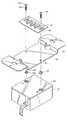
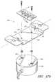
- FIG. 6is a perspective view of another embodiment of an LED-based luminaire having aspects of the present invention.
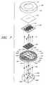
- FIG. 7is an exploded view of the embodiment illustrated in FIG. 6 .
- FIG. 8is a schematic cross-sectional cutaway view of an embodiment of a power driver suitable for use in connection with the embodiment shown in FIG. 6 .
- FIG. 9 ais an exploded view of components of an embodiment of a power driver suitable for use in connection with the embodiment illustrated in FIG. 6 .
- FIG. 9 bis another exploded view taken from an opposite perspective from the exploded view of FIG. 9 a.
- FIG. 10is a schematic electrical circuit diagram representing a circuit configuration of an embodiment of a power driver as in FIGS. 8 and 9 .
- FIG. 11 ais a schematic view of a first side of a mount board of the power driver of FIG. 8 .
- FIG. 11 bis a schematic view of a second side of the mount board of FIG. 11 a.
- FIG. 12 ais a schematic view of a first side of a power conditioning board of the power driver of FIG. 8 .
- FIG. 12 bis a schematic view of a second side of the power conditioning board of FIG. 12 a.
- FIG. 13illustrates certain electrical components partially encased within a hardened resin, which components are adapted to engage the power conditioning board of FIGS. 12 a and 12 b.
- FIG. 14 ais a partially cutaway side view of another embodiment of an LED-based luminaire.
- FIG. 14 bis a partial front view of the embodiment illustrated in FIG. 14 a.
- FIG. 15is a perspective view of another embodiment of a power driver that may be used in connection with certain embodiments of LED-based luminaires.
- FIG. 16is an exploded view showing internal componentry of the power driver of FIG. 15 .
- FIG. 17 ais an exploded view of another embodiment of a LED-based luminaire arranged in a first configuration.
- FIG. 17 bis an exploded view of the LED-based luminaire of FIG. 17 a arranged in a second configuration.
- FIG. 18is a plan view of another embodiment of an LED module suitable for use in yet another embodiment.
- FIG. 19illustrates an embodiment of a channel illumination apparatus employing a plurality of the LED modules of FIG. 18 .
- the LED-based luminaire 30comprises a lighting module 32 having one or more LEDs 34 disposed thereon, a mount member 36 , and a power driver 40 for conditioning and delivering power to the lighting module.
- a pair of threaded fasteners 42secure the lighting module 32 onto the mount member 36 and the driver 40 .
- the fasteners 42preferably extend through apertures 44 , 46 formed through the lighting module 32 and mount member 36 , and engage threaded mount bosses 50 in the driver 40 .
- Non-conductive inserts 52electrically insulate the mount member 36 and portions of the module 32 from the fasteners 42 .
- the mount bosses 50 in the driver 40are polarized, which is to say a voltage drop is provided across the mount bosses 50 .
- the fasteners 42are configured to conduct electricity in addition to securing the lighting module 32 into place. As such, preferably electric power is communicated across the lighting module 32 via the fasteners 42 , which contact the mount bosses 50 of the power driver 40 .
- an embodiment of a lighting module 32preferably comprises a module body 54 upon which a plurality of electrically-conductive circuit traces/contacts 60 are deposited.
- the contacts 60are electrically insulated relative to one another.
- a pair of module apertures 44are formed through the module body 54 .
- Positive and negative input contacts 60 +, 60 ⁇are formed at or adjacent the apertures 44 .
- a plurality of prepackaged LEDs 34are mounted on the lighting module 32 so as to be arranged electrically in series between the positive 60 + and negative 60 ⁇ input traces.
- the lighting module 32employs three LEDs arranged in series.
- Embodiments of a suitable lighting moduleinclude aspects as described in Applicant's co-pending U.S. patent application Ser. No. 10/928,910, entitled “LED Luminaire,” which was filed on Aug. 27, 2004, the entirety of which is hereby incorporated by reference.
- the lighting module 32comprises three LEDs 34 arranged electrically in series between the positive and negative 60 +, 60 ⁇ . It is to be understood, however, that several different configurations of lighting modules can be employed depending on the application or a user's preference. For example, only a single LED, or several LEDs, may be provided on each lighting module. In additional embodiments, LEDs may be arranged on the module in a parallel arrangement, or a combination of series and parallel.
- modulesmay be square, circular, oval, irregularly-shaped or may have widely varying rectangular dimensions (such as being especially long and thin).
- modulesare relatively flat, it is understood that other embodiments may include modules having simple or complex three dimensional shapes.
- the body 54 of the lighting module 32can be made of various materials, rigid or flexible. However, most preferably, the body comprises a generally rigid heat conductive material such as aluminum. Preferably, the body 54 is constructed of a material having high heat conductance properties such as a heat conductivity greater than about 75 W/m*K and most preferably greater than about 100 W/m*K. As such, the body will absorb heat generated by the LEDs, and will draw the heat away from the LEDs.
- the LEDs 34may be all the same color, may be of different colors, or may include combinations of LED colors that are specifically tailored to create a particular color effect. For most space lighting applications the LEDs preferably emit white light.
- the illustrated mount member 36preferably is elongate and comprises fixture mount surfaces 68 arranged on opposite sides of a module mounting field 70 that is located generally centrally in the mount member 36 .
- Mount apertures 46are formed in the mount field 70 and are adapted to generally align with module apertures 44 formed in the module 32 .
- the elongate fasteners 42are adapted to extend through both the module apertures 44 and the mount apertures 46 to secure the module 32 in place on the mount field 70 .
- the mounting field 70preferably is substantially flat so as to complement the flat body 54 of an associated lighting module 32 .
- the lighting modulemay have an irregular or curving surface that preferably is configured to complement the lighting module body surface.
- heatis readily transferred from the lighting module body 54 to the mount member 36 .
- the mount memberis made of a material having relatively high heat conductance properties, such as metal.
- the mount member 36is constructed of a single piece of aluminum.
- One or more fixture mount apertures 72preferably is disposed in each of the fixture mount portions 68 of the mount member.
- One or more of these fixture mount apertures 72preferably is employed to secure the mount member 36 to its designated location. More specifically, for example, the fixture mount apertures 72 may align with bolt or screw holes in an electrical junction box or the like so as to enable mounting of the mount member 36 in an electrical junction box.
- one or more of the fixture mount apertures 72corresponds with mounting bolts of another type of lighting fixture. It is to be understood that, in other embodiments, the mount member may have other shapes and configurations so as to fit as desired relative to a lighting fixture so as to provide the light source for the lighting fixture.
- the mount member 36is bent to create a transversely-directed offsetting portion 74 between the fixture mount portion 68 and the mounting field portion 70 of the mount member 36 .
- the mounting field 70is offset from the fixture mount portion 68 .
- the offset 74provides a space for the lighting module 32 to be mounted to the mount field 70 in a fixture embodiment in which a face of the fixture is substantially flush with the fixture mount portion 68 .
- one or more ground apertures 76are provided in the mount member for supplying a connection to electrical ground when desired.
- heat from the LEDs on the lighting module 32is communicated to the heat conductive module body 54 , which in turn communicates the heat to the mount member 36 .
- the mount memberacts as a heat sink, absorbing the heat from the lighting module and thus communicating heat away from the LEDs 34 . Since LEDs tend to deteriorate very quickly if subjected to excessive heat, the mount member's operation as a heat sink can provide a valuable role in ensuring longevity of an associated LED luminaire.
- the mount member 36which functions as a heat sink, preferably accumulates heat and disperses such heat to the environment.
- the mount member 36is formed of aluminum and is powder coated. Most preferably the powder coat is a glossy white color and has a rough or bumpy surface texture. In a preferred embodiment, the overall surface area of the mount member is increased significantly by the bumpy powder coat relative to flat metal. In one embodiment, the overall surface area due to the rough-textured powder coat is increased by up to about three times relative to a smooth flat metal surface. In another embodiment, the surface area is at least about doubled.
- Coating the mount member 36 with a bumpy-textured coatingmay not always vary the surface area extensively. However, changing the surface texture of the raw metal increases its heat transfer properties.
- the mount membermay be a polished or unpolished aluminum.
- Application of a covering such as a visibly bumpy-surface powder coatchanges the surface texture of the device. Applicants have learned that adding a rough surfaced, bumpy powder coat to a raw or polished aluminum mount member improves the heat conductivity properties of the mount member. Specifically, Applicant has measured temperature decreases between about 30-50% when a bumpy white powder coated mount member heat sink is used in place of a raw metal mount member heat sink.
- Applicanthas also noted improved heat conductance properties and decreased measured temperatures relative to raw metal even when the mount member is powder coated with a relative smooth powder coat.
- the mount memberis coated with a light-and heat-reflective color, such as gloss or semi-gloss white; however, other colors may be used.
- the mount member 36is coated with a coating having a visibly bumpy texture.
- the bumpy texturecreates many peaks and valleys in the surface.
- a feature heightis defined as a height of a peak relative to its adjacent valley.
- An average feature heightis, of course, an average of such measurements, and gives an indication of the bumpiness of the surface.
- the bumpy powder coatingdoes not simply increase the surface area of the mount member relative to raw metal. Rather, the bumpy powder coating increases the average feature height of the surface of the mount member. Most preferably, the coating is configured to increase the average feature height so as to increase incident air access to and interaction with the peaks and valleys that make up the bumpy surface. Such increased incident air interaction increases the ability of the environmental air to extract heat from the mount member.
- some raw metalssuch as aluminum may appear generally flat to the human eye, but in fact include several peaks and valleys having a relatively low average feature height.
- a bumpy powder coatmay not necessarily increase the surface area of such a raw metal substantially. However, the bumpy powder coat preferably increases the average feature height significantly, and thus increases the ability of the mount member to transfer heat to the environment, relative to a mount member having an uncoated metal surface. The increased average feature height increases the efficiency of heat transfer relative to unfinished aluminum.
- the LEDs 34 of the lighting module 32emit white light.
- the LED packageincludes red phosphors.
- a spectral distribution curve of the warm white light emitted by such LEDsshows a significant amount of infrared light in the spectrum.
- infrared lightreadily communicates energy to whatever material it impinges upon, which energy typically is converted to heat within the material. If a mount member were untreated, or were colored black as are conventional heat sinks, such infrared light energy would increase the temperature of the heat sink, thus diminishing its effectiveness as a heat sink.
- a light-reflective colorsuch as gloss or semi-gloss white, reflects infrared light rays as well as other colors of light, and thus minimizes the accumulation of infrared light energy by the heat sink.
- light energy from the infrared lightis not transferred to the heat sink, but rather is directed to the environment.
- the effectiveness of the heat sink in extracting heat from the LEDsis enhanced, as less energy is being absorbed by the heat sink.
- the light-reflective coatingis applied even in areas of the device that are not visible to the outside or to a user looking at the device.
- heat sinksare painted black in order to better absorb heat.
- the mount memberwhich functions as a heat sink, preferably is painted a light-reflective color.
- the light-reflective heat sinkhas increased capacity relative to a conventional black or otherwise low-reflectivity heat sink.
- a visibly bumpy-surfaced semi-gloss white powder coatis employed.
- One suitable powder coatis a polyester TGIC powder coating (TC 13-WH09), which is available from Cardinal Industrial Finishes.
- the power driver 40comprises a housing 80 that encloses electrical components and circuitry for power conditioning.
- a pair of flexible conductors 82are configured to connect to line voltage such as 120 VAC and to communicate such line voltage to the driver componentry.
- the componentry within the driver 40steps down the voltage and rectifies it into a DC voltage that is appropriate for driving the LEDs 34 on the module 32 .
- the voltageis stepped down to 6-10 volts.
- a switching mechanism 84is provided to customize the power conditioning desired by the user.
- the usermay choose low, medium, and high brightness settings.
- the componentry and circuitry within the power driver 40preferably is configured so that when each switching configuration (switches 1 and 2 are both off; 1 is on, 2 is off; 1 is off, 2 is on; or 1 and 2 are both on) is associated with a configuration of the circuit that results in a different brightness or control setting, resulting in different power supply characteristics being provided to the lighting module.
- the associated circuitry and/or a control system within the housingis configured to vary the voltage, current supply, duty cycle, or the like as needed in accordance with known principles and componentry.
- electrical componentry of the driver 40can resemble that discussed in connection with another embodiment discussed below.
- mounting bosses 50are arranged within the driver 40 , and are configured to align with the lighting module apertures 44 and mount member apertures 46 so that the elongate fasteners 42 extending through the apertures engage the mounting bosses 50 .
- the mounting bossesare polarized, meaning that there are configured as part of a circuit path so that when a module 32 is properly installed it bridges from a positive to a negative boss, 50 +, 50 ⁇ thus completing a circuit and supplying electrical power to the module 32 .
- the mount bosses 50are threaded so as to engage threads of the elongate fasteners 42 . Electric power is communicated through the mounting bosses to the fasteners and from the fasteners to the positive and negative circuit traces 60 +, 60 ⁇ formed on the lighting module 32 , and in turn through the LEDs 34 .
- the housingincludes an outer case 90 and a front plate 92 that complementarily engage one another. Apertures 94 are formed through the plate 92 so as to correspond with the mounting bosses 50 . Preferably, the plate apertures 94 are somewhat larger in diameter than the threaded engagement portion 96 of the mount bosses 50 . Preferably positive and negative legends are embossed on the plate 92 .
- the exploded viewshows how the lighting module 32 , mount member 36 , and power driver 40 preferably are connected to one another.
- the lighting module 32is on one side of the mount member 36 and the power driver 40 is on the opposite side of the mount member 36 .
- the fasteners 42each comprise a head portion 100 and a threaded elongate shaft portion 102 which extends through the associated module aperture 44 and mount aperture 46 and engage the corresponding mount boss 50 .
- the fastener heads 100engage the corresponding positive or negative input trace 60 +, 60 ⁇ of the module.
- the mount bosses 50are polarized and the fasteners 42 preferably are electrically conductive.
- the heads 100 of the electrically-conductive fastenerscommunicate electrical power from the driver bosses 50 to the positive and negative input traces 60 +, 60 ⁇ of the module.
- a pair of non-conductive inserts 52are provided to electrically insulate the fasteners 42 from the mount member 36 and body portion 54 of the lighting module 32 .
- Each insert 52preferably comprises a flange portion 104 and a shank portion 106 .
- the shank 106is configured to fit through the mount member aperture 46 and at least part of the module aperture 44 , and accepts part of the corresponding threaded fastener 42 therethrough.
- the inserts 52are electrically nonconductive, the inserts electrically insulate the threaded fasteners 42 from the mount member 36 and the body 52 of the lighting module 32 .
- the flanges 104 of the inserts 52preferably are configured to fit within the housing plate 92 apertures 94 so as to maintain the position of the inserts 52 without interfering with the position of the mount member 36 upon the driver 40 .
- FIG. 6Another embodiment of an LED-based luminaire 130 is illustrated.
- This figureshows an entire standalone light fixture 131 that is adapted to be connected to standard home 120 VAC wiring.
- the fixture 131comprises a cover 134 attached to a mounting base 136 .
- a back housing 138is also provided.
- a power conditioning device 140 within the back housing 136is preferably enclosed.
- FIG. 7presents an exploded view of the embodiment illustrated in FIG. 6 but not showing the back housing.
- the illustrated embodiment 130employs three LED-based lighting modules 32 A-C that are configured to fit in a module mounting portion 142 of the mount base 136 .
- the module mounting portion 142is specifically configured to accommodate all three modules 32 A-C.
- the module mounting portion 142 of the base 136is offset from a front surface 143 of the base so that the lighting modules are offset inwardly relative to the front surface 143 .
- the mounting portion 142is shaped so as to complement the shape of the lighting modules 32 A-C.
- the module mounting portion 142is substantially rectangular and flat-surfaced so as to complementarily accommodate the lighting modules.
- Module apertures 44are formed through each lighting module 32
- three pairs of mounting base apertures 146 A-Care formed through the mounting base 136 in the mount portion 142 to correspond with the module apertures 44 .
- a power conditioner or driver 140is configured to be placed on a side of the mount base 136 opposite the lighting modules 32 .
- the power driver 140receives electrical input power from a power source through electrical wires 148 .
- the driver 140also comprises three pairs of mounting bosses 50 A-C. Each pair of mounting bosses 50 A-C is configured to power a corresponding lighting module 32 A-C.
- threaded fasteners 42are configured to fit through the lighting module apertures 44 , mounting base apertures 146 , through an insert 52 , and into secure contact with corresponding mount bosses 50 A-C of the power driver 140 in a manner as discussed above.
- the fasteners 42secure the lighting modules 32 A-C and power driver 140 to the mounting base 136 , and the fasteners 42 also deliver electrical power from the driver bosses 50 A-C to corresponding modules 32 A-C.
- the mounting base 136is preferably formed from a material having advantageous heat conductance properties, such as aluminum. As such, the mounting base may operate as a heat sink, absorbing heat generated by the LEDs 34 and dispersing that heat to the environment. In the illustrated embodiment, the base 136 is constructed as a single piece of aluminum. In other embodiments, multi-piece bases may be employed. As discussed above, the portion 152 of the mounting base 136 surrounding the module mounting portion 142 is raised in the illustrated embodiment. Preferably fins 154 are provided in the raised portion 152 of the mounting base 136 . Such fins 154 help speed heat transfer from the mounting base to the environment. In the illustrated embodiment, fins are illustrated on the front side of the mounting base 136 . It is to be understood that certain fin structures may also be formed in a back side of the mounting base.
- the mounting base 136preferably is powder coated with a bumpy-textured powder coat that creates many peaks and valleys whose feature heights are significant enough on average to enhance heat transfer relative to an unfinished metal base or flat-coated base.
- the back housing 138 illustrated in the embodiment shown in FIG. 6need not be included in all embodiments. For example, in some embodiments the back portion of the light fixture will not be accessible or visible, and an installer may determine that back housing 138 is not desired
- a light modifying device 160is adapted to rest on the front face 143 of the base 136 substantially in front of the LEDs 34 .
- the illustrated lens 160is specifically configured for the illustrated embodiment, which comprises three modules that each comprises three LEDs.
- the lens 160comprises nine lens portions 162 , one portion corresponding to each LED.
- each lens portionis specially adapted to collimate light from the corresponding LED.
- each lens portionpreferably is adapted to provide a total internal reflection of LED light in order to maximize the usefulness of the light emitted from each LED.
- the lens 160may be colored or clear, and preferably, comprises kinoform diffusers that are adapted to direct the collimated LED light in a desired shape and/or direction.
- the protective plate 164preferably is transparent or translucent, and communicates light from the LEDs 34 therethrough while simultaneously protecting components from access from outside the fixture.
- a housing face, or cover 134preferably is configured to lockingly engage to the base 136 and encloses the protective plate 164 , lens portion 160 , lighting modules 32 and a portion of the base 136 .
- the face 134also comprises a heat conductive material, such as aluminum, that preferably is powder coated. Since the face likely is the most visible portion of the LED luminaire 130 , it is anticipated that in certain embodiments a bumpy-surfaced powder coating will be visually undesirable. Nevertheless, even though a raw metal look is acceptable, it is most preferable that the face 134 at least have a smooth powder coat or layer of paint. In any case, it is anticipated that, in some embodiments, internal components such as the base 136 may be rough-texture powder coated, while external portions such as the face 134 may be uncoated or have a different type of surface coating/texture.
- the face 134includes an internal spacer 170 that generally corresponds to the protective plate 164 and lens 160 so as to the control the position of the protective plate and the lens member relative to the position of the LEDs 34 .
- the spacer 170preferably depends inwardly from the front portion of the face/cover 134 .
- the faceis mounted on the base plate 136 so that the spacer 170 contacts the front 143 of the mounting base.
- the spacer 170 and the fins 154are sized so that at least a portion of the fins 154 are exposed, allowing heat within the area between the LED modules and the housing face plate to vent through the fins.
- a pair of threaded holes 172are provided on either side of the cover 134 .
- a pair of opposing seats 174are defined on the mounting base.
- headless boltssuch as grub screws, are threaded into the cover holes 172 so as to engage the corresponding seat 174 formed in the mounting base 136 .
- the fixture 130preferably can be mounted in several different ways.
- the mounting base 136preferably includes a pair of slide mount fixture apertures 180 .
- Each slide mount aperturepreferably has a first portion 182 with a relatively large diameter, which portion is configured to accept a mount bolt head.
- An elongate, second portion 184 of the slide mount aperture 180has a smaller width, and is sized to accommodate a shaft portion of the mount bolt without allowing the bolt head to fit therethrough.
- a mount bolt headis advanced through the first portion 182 and then the mounting base 136 is rotated so that the mount bolt shaft seats in the second portion 184 , thus holding the mount base in place on the mount bolt.
- apertures 186are also formed through the mounting base 136 in order to accommodate bolts and/or screws advanced directly through the mounting base. Still further, at least some of such apertures 186 include a plurality of threaded holes adapted to accommodate threaded bolts in order to mount the base 136 in place.
- each of these mounting optionsare included in the mounting base, thus providing several options for mounting. It is to be understood that still further mounting options can be employed as well.
- the illustrated embodimentincludes another pair of threaded holes 188 along the edges of the mounting base. If desired, a gimbal mechanism can be attached to the mounting base at the threaded edge mount holes 188 , and the gimbal mechanism can be used to mount the fixture.
- the driver 140preferably is configured to receive line voltage input through the wires, and output an appropriate DC voltage through the mounting bosses.
- the driveris configured to receive 120 VAC and transform it to about 30 VDC output of about 25 watts and 450 mA.
- the drivercomprises a housing 190 that encloses electrical componentry.
- a pair of spaced apart electrically connected circuit boards 192 , 194is enclosed within the housing.
- a dielectric sheet 196is disclosed between the circuit boards 192 , 194 , and resists electrical interaction between the boards 192 , 194 .
- a mount circuit board 194comprises the mounting bosses 150 .
- the mount board 194is electrically connected to a power conditioning board 192 , which comprises certain electrical components configured to step-down and condition an input voltage.
- FIGS. 9 a and 9 ban exploded view of a preferred embodiment of a driver 140 illustrates the circuit boards 192 , 194 , dielectric 196 , and certain electrical components.
- a circuit diagram 200representing electrical componentry of a preferred embodiment of a driver is depicted.
- input electrical powersuch as from line voltage
- a fuse 204is provided for safety purposes.
- the circuitincludes a portion 206 for stepping the input voltage down to a desired voltage.
- the step-down portion 206comprises a plurality of resistors R 1 , R 2 , R 3 , R 4 arranged in parallel with a plurality of capacitors C 1 , C 2 , C 3 , C 4 , C 5 .
- step-down portion 206enables the driver to step down the voltage without requiring a bulky, heat-producing transformer.
- the circuit 200includes a rectifying arrangement 208 comprising diodes D 1 , D 2 , D 3 , D 4 arranged in a manner to rectify the supplied AC current into a DC current.
- the step-down and rectifying portions 206 , 208 of the circuit 200are arranged on the power conditioning board 192 .
- Connectors 210are supplied for electrically connecting the power conditioning board 192 to the mount board 194 .
- the power conditioning boardpreferably comprises the three pairs of mount bosses 150 A-C. In the illustrated embodiment the pairs of bosses are arranged in electrical series relative to one another.
- diodes D 5 , D 6 , D 7are provided to allow some back current to flow, but prevent forward current from flowing between the bosses. Instead, current is forced to flow through a lighting module attached to the bosses.
- the illustrated circuit 200not only steps down and rectifies voltage, but provides that voltage evenly across the pairs of mounting bosses 150 A-C.
- three LED modules 32 A-Care attached to the bosses 150 A-C as illustrated above in FIGS. 6 and 7 , a circuit is completed from the driver 140 through the first lighting module 32 A, back into the driver, to the second lighting module 32 B, back into the driver, and lastly to the third lighting module 32 C and back to the driver 140 .
- standardized lighting modules 32can be individually replaced, as substantially all power delivery circuitry is enclosed within the driver 140 .
- a driver having only a pair of mount bossescan be provided in connection with a lighting module having several LEDs arranged in any desired geometric and electrical arrangement, but designed to correlate with the driver's power supply characteristics.
- three identical lighting modules 32 A-Care employed. It is to be understood that, in other embodiments, various geometrical configurations can be employed. As such, three or more, or less, lighting modules 32 can be employed in other embodiments, and the lighting modules need not necessarily be the same size and/or shape and may not necessarily employ the same number or color of LEDs. For example, in certain lighting fixtures having other geometric configurations, it may make sense to have smaller lighting modules and larger lighting modules that are powered by the same driver. Preferably, the lighting modules can be connected to a driver without requiring additional wiring between the modules. Principles and aspects discussed in the above embodiments disclose a simple manner of connecting individual modules in place wherein the connection provides both the electric supply and physical connection.
- one or more modules of a multimodule luminairemay be removed and replaced independent of the other modules. It is to be understood that, in other embodiments, additional physical connectors that are not electrically conductive may also be employed with certain lighting modules. Also, principles and aspects discussed herein may be employed in embodiments in which physical connection and electrical connection are not simultaneously supplied through fasteners.
- the illustrated circuit diagramanticipates a 120 VAC input. However, it is to be understood that the principles disclosed herein can be employed in connection with other input voltage, such as 240 vac or high- and low-voltage AC inputs. Of course, changes and enhancements can be made, and additional features can be added to the circuit diagram 200 disclosed in FIG. 10 without detracting from the teachings or operability thereof.
- a power driver 140 for the illustrated multimodule LED-based luminaire 130preferably the input wires 148 connect to the power conditioning board 192 at input connector holes 220 .
- the power conditioning board 192has a first side 222 and a second side 224 , and circuit traces are formed on both sides. From the input connector holes 220 , a first side trace 226 delivers power to the capacitors C 1 -C 5 at respective capacitor positive mount holes 230 .
- the capacitor mount holes 230 for capacitor C 5transmits electricity through the board 192 to the second side of the board 224 , and a second side trace 236 leads to the resistors R 1 -R 4 and to the negative side capacitor mount holes 240 .
- the trace 236then leads power to the rectifying arrangement 208 of diodes D 1 -D 4 from which a positive component of power is directed along a trace 242 to a positive connector/spacer 210 + and a negative component of power is directed along a trace 244 to a negative connector/spacer 210 ⁇ .
- a negative power input trace 246connects to a fuse mount hole 248 which directs electrical power through the fuse 204 and to the negative input connector hole 220 ⁇ .
- three spacer members 210connect the power conditioning board 192 to the mount board 194 .
- a positive spacer/connector 210 + and a negative spacer/connector 210 ⁇conduct electricity to the mount board 194 .
- the positive spacer/connector 210 +attaches to the mount board 194 so that positive electrical energy is applied to a positive trace 256 on the second side 252 of the mount board 194 . Electrical energy is thus delivered to a positive node 150 C+ of a first pair of mount bosses 150 C.
- electric powerwill pass through the first lighting module 32 C to the negative pole 150 C ⁇ of the first pair of mounting bosses 150 C.
- a trace 258 on the first side 250 of the mount board 194delivers electrical power to the positive pole 150 B+ of a second pair of bosses 150 B.
- a trace 260 on the second side 252 of the board 194delivers power to a positive pole 150 A+ of the third pair of bosses 150 A.
- electrical energyis delivered to the negative spacer/connector 210 ⁇ .
- the first side 250 of the mount board 194comprises diodes D 5 , D 6 , D 7 arranged in circuit traces 262 between each pole of the paired mount bosses 150 . However, such diodes are arranged to prevent electrical flow from the plus to minus direction, and thus do not interfere with delivery of power to the lighting modules 32 .
- electric components that are connected to the first side 222 of the power conditioning board 192are at least partially enveloped in a hardened resin 270 in order to hold such components securely in place, and improve the durability of the driver.
- a hardened resin 270is first poured into the driver housing 190 .
- the assembled circuit boards 192 , 194are placed in the housing 190 .
- the hardened resin 270has minimal, if any, interaction with the power conditioning board 192 itself.
- a plurality of capacitor spaces on the power conditioning board 192are unused, as are other component spaces.
- the illustrated boardmay be used in other embodiments employing more, less, or different capacitors and other components while maintaining its interchangeable size.
- the driver 140can be further specialized for different embodiments while maintaining its size and general configuration.
- each post 280engages the mounting bosses 282 of an embodiment of a driver 284 .
- the posts 280are energized and extend outwardly from the driver 284 .
- each post 280has a clip 286 attached to a distal end thereof.
- each post 280extends through a mount aperture 288 formed in the mount member 290 .
- a lighting module 292employing LEDs 34 having an input trace 294 , an output trace 296 , and one or more LEDs arranged thereon is provided.
- the LED lighting module 292has no mount apertures. Instead, in the illustrated embodiment, the lighting module 292 is slipped under the clips 286 and held securely in place by the clips 286 , which preferably are spring loaded. The opposing clips engage opposing poles of the positive and negative input traces.
- the post 280may threadingly engage the mount boss 282 ; the post 280 may be integrally formed with or have an interference fit with the mount boss, and the clip portion 286 may be detachably connected to the post; the post may connect to the mount boss in a “bayonet”-type connection, or the like.
- FIGS. 14 a and billustrate just one variation for connecting a module 292 to a mount member 290 and to a driver 284 on the opposing side of the mount member. Other variations for connecting a lighting module to a mount member and driver may also be employed.
- a lighting modulehas one aperture that is larger than the other mount aperture, as does the mount member.
- Each pole of the mounting bosses in the driverhas a diameter corresponding to the appropriate module aperture. As such, it will be difficult or impossible to connect the input traces to the incorrect pole of the driver, because different sizes of fasteners will be employed for each pole.
- Other mounting mechanismsmay employ spring loaded members, other clip configurations, or the like.
- a driver 300having a generally cylindrical housing shape.
- the driver 300is still configured to receive electrical input, condition the electrical input as desired, and provide output at mounting bosses 302 arranged within the driver 300 but which are accessible through a driver housing 304 .
- an embodiment of a driver 300may employ a power conditioning board 310 , a mount board 312 , a separator 314 and the like in a manner quite similar to that discussed above.
- a circuit boards and componentsare configured to fit within the generally cylindrical housing 304 .
- a modular lighting system 320 employing such a cylindrical driver 300may have significantly increased versatility over more traditional systems.
- a mount member 36is provided having two pairs of mounting apertures 322 , 324 .
- the first pair of mounting apertures 322is employed, thus resulting in a device 30 having substantially the same configuration as the device illustrated in connection with FIGS. 1 and 2 .
- the second mounting apertures 324are employed.
- the lighting module 32is arranged along a longitudinal axis 326 of the mount member 36 as opposed to the configuration of FIG. 17 a in which the lighting module 32 is arranged generally transverse to the longitudinal axis 326 of the mount member 36 .
- the power driver 300is rotated in order to align with the LED module 32 and second mount apertures 324 .
- rotation of the driver 300creates substantially no change in the footprint shape of the driver 300 on the mount member 36 or within an associated light fixture, even though the arrangement of the lighting module 32 and thus the spacing of the LEDs and shape of the emitted light is different than in the embodiment of FIG. 17 a .
- This type of systemallows more versatility in creating light fixtures having light of various patterns or the like without requiring specialized parts, especially drivers, for each configuration.
- a modular light fixture creation systemis envisioned in which a minimum of basic parts, namely drivers, modules, mount members and the like can have marked versatility and selectively be assembled in various configurations.
- the embodiment of FIGS. 17 a and bcan be assembled into significantly different configurations without changing the footprint of the overall LED-based luminaire.
- an LED-based lighting module 332is provided.
- a pair of LEDs 34are disposed on circuit traces 334 so as to be in an electrically series arrangement.
- Flexible conductors 338are attached to a positive 340 and negative 342 trace, respectively adjacent a first end 344 of the module 332 .
- Positive and negative conductorsare also attached to positive and negative traces 340 , 342 , respectively, adjacent a second end 346 of the module 332 .
- a plurality of such modules 332can be connected end-to-end in a daisy chain type of arrangement so that the modules are in an electrically parallel arrangement relative to one another.
- the modules 332are fairly elongate, and can be up to several inches in length if desired.
- a channel illumination apparatus 350comprising a casing 352 in the shape of a “P.”
- the casing 352includes a plurality of walls 354 and a back 356 , which together define at least one channel 360 .
- a chain of several modules 332is linked together and attached to a surface of the casing 352 .
- the modules 332are adhered to the surface with a heat conductive tape.
- the surfaces of the walls 354 and bottom 356are coated with a light reflective coating.
- the walls 354are preferably formed of a durable sturdy metal having relatively high heat conductivity.
- a translucent light diffusing lens(not shown) is preferably disposed on a top edge of the walls, and encloses the channel 360 .
- the modulesWith the daisy chain of modules 332 arranged in the channel 360 , the modules can be lit, and thus creating a lighted channel sign 350 .
- the walls 354 and back 356 of the channel casing 352are coated with a powder coat that is visibly bumpy-textured.
- the powder coatis a semigloss or glossy white color. Most preferably, however, it is simply a light-reflective color.
- the powder coatis sufficiently bumpy so as to have a feature height that enhances heat transfer to the environment.
- the casing walls 354 and back 356preferably have a high heat conductivity, and can function as a heat sink, preferably the light energy emitted by the lighting modules 332 is directed away from the heat sink material.
- the bumpy powder coatenhances heat transfer from the heat sink material to the environment.
- an outer surface of the heat sink materialis also powder coated, preferably with a bumpy-textured powder coat. Even if such outside surface is not appropriately colored white, or even a light reflective color, heat transfer from the heat sink can be enhanced.
Landscapes
- Engineering & Computer Science (AREA)
- General Engineering & Computer Science (AREA)
- Physics & Mathematics (AREA)
- Geometry (AREA)
- Power Engineering (AREA)
- Non-Portable Lighting Devices Or Systems Thereof (AREA)
- Arrangement Of Elements, Cooling, Sealing, Or The Like Of Lighting Devices (AREA)
Abstract
Description
Claims (24)
Priority Applications (2)
| Application Number | Priority Date | Filing Date | Title |
|---|---|---|---|
| US11/434,663US7918591B2 (en) | 2005-05-13 | 2006-05-15 | LED-based luminaire |
| US13/080,518US20120176795A1 (en) | 2005-05-13 | 2011-04-05 | Led-based luminaire |
Applications Claiming Priority (2)
| Application Number | Priority Date | Filing Date | Title |
|---|---|---|---|
| US68107205P | 2005-05-13 | 2005-05-13 | |
| US11/434,663US7918591B2 (en) | 2005-05-13 | 2006-05-15 | LED-based luminaire |
Related Child Applications (1)
| Application Number | Title | Priority Date | Filing Date |
|---|---|---|---|
| US13/080,518ContinuationUS20120176795A1 (en) | 2005-05-13 | 2011-04-05 | Led-based luminaire |
Publications (2)
| Publication Number | Publication Date |
|---|---|
| US20070041220A1 US20070041220A1 (en) | 2007-02-22 |
| US7918591B2true US7918591B2 (en) | 2011-04-05 |
Family
ID=37767170
Family Applications (2)
| Application Number | Title | Priority Date | Filing Date |
|---|---|---|---|
| US11/434,663Expired - Fee RelatedUS7918591B2 (en) | 2005-05-13 | 2006-05-15 | LED-based luminaire |
| US13/080,518AbandonedUS20120176795A1 (en) | 2005-05-13 | 2011-04-05 | Led-based luminaire |
Family Applications After (1)
| Application Number | Title | Priority Date | Filing Date |
|---|---|---|---|
| US13/080,518AbandonedUS20120176795A1 (en) | 2005-05-13 | 2011-04-05 | Led-based luminaire |
Country Status (1)
| Country | Link |
|---|---|
| US (2) | US7918591B2 (en) |
Cited By (44)
| Publication number | Priority date | Publication date | Assignee | Title |
|---|---|---|---|---|
| US20080278957A1 (en)* | 2007-05-07 | 2008-11-13 | Cree Led Lighting Solutions, Inc. | Light fixtures and lighting devices |
| US20090296414A1 (en)* | 2008-05-30 | 2009-12-03 | Toshiba Lighting & Technology Corporation | Lighting apparatus and substrate having plurality of light-emitting elements mounted thereon and incorporated in this lighting apparatus |
| US20100067226A1 (en)* | 2008-09-16 | 2010-03-18 | Toshiba Lighting & Technology Corporation | Light source unit and lighting apparatus having light-emitting diodes for light source |
| US20100117560A1 (en)* | 2006-10-03 | 2010-05-13 | Cao Group, Inc. | Pixilated LED Light Source for Channel Letter Illumination |
| US20100128491A1 (en)* | 2008-11-25 | 2010-05-27 | Toshiba Lighting & Technology Corporation | Recessed luminaire |
| US20100157610A1 (en)* | 2008-12-22 | 2010-06-24 | Fu Zhun Precision Industry (Shen Zhen) Co., Ltd. | Led lamp |
| US20100208460A1 (en)* | 2009-02-19 | 2010-08-19 | Cooper Technologies Company | Luminaire with led illumination core |
| US20110069493A1 (en)* | 2009-09-24 | 2011-03-24 | Huan-Chang Huang | LED Assembly |
| US20110075427A1 (en)* | 2009-09-25 | 2011-03-31 | Toshiba Lighting & Technology | Lighting apparatus |
| US20110205752A1 (en)* | 2010-02-24 | 2011-08-25 | Allen Derek J | Lighting Device |
| US20110285298A1 (en)* | 2007-09-14 | 2011-11-24 | Osram Gesellschaft Mit Beschraenkter Haftung | Illumination Module |
| US20120087137A1 (en)* | 2010-10-08 | 2012-04-12 | Cree, Inc. | Led package mount |
| USD662653S1 (en)* | 2011-11-29 | 2012-06-26 | Full Throttle Films, Inc. | Linear lighting track mount |
| USD663068S1 (en)* | 2011-11-29 | 2012-07-03 | Full Throttle Films, Inc. | Linear lighting track |
| US20130088866A1 (en)* | 2010-06-18 | 2013-04-11 | Vialuminary Ltd. | Led street light |
| USD690857S1 (en) | 2011-03-29 | 2013-10-01 | Cooper Technologies Company | Light-emitting diode (LED) floodlight |
| US20130286645A1 (en)* | 2011-01-11 | 2013-10-31 | Koninklijke Philips N.V. | Lighting device |
| US20140168954A1 (en)* | 2012-12-14 | 2014-06-19 | David Gershaw | Led panel light fixture |
| US8866406B2 (en) | 2011-09-26 | 2014-10-21 | Musco Corporation | Lighting system having a multi-light source collimator and method of operating such |
| US8911116B2 (en) | 2011-04-01 | 2014-12-16 | Cooper Technologies Company | Light-emitting diode (LED) floodlight |
| US20150212263A1 (en)* | 2014-01-29 | 2015-07-30 | Hsiu-Yu Hsu | Led decorative lighting |
| US9140441B2 (en) | 2012-08-15 | 2015-09-22 | Cree, Inc. | LED downlight |
| US9151477B2 (en) | 2012-02-03 | 2015-10-06 | Cree, Inc. | Lighting device and method of installing light emitter |
| US9151457B2 (en) | 2012-02-03 | 2015-10-06 | Cree, Inc. | Lighting device and method of installing light emitter |
| USD742581S1 (en)* | 2013-12-09 | 2015-11-03 | Kenall Manufacturing Company | Driver housing |
| US20150345719A1 (en)* | 2014-05-28 | 2015-12-03 | Self Electronics Usa Corporation | Bar-Typed Double-Row LED Lighting |
| US9310038B2 (en) | 2012-03-23 | 2016-04-12 | Cree, Inc. | LED fixture with integrated driver circuitry |
| US9316382B2 (en) | 2013-01-31 | 2016-04-19 | Cree, Inc. | Connector devices, systems, and related methods for connecting light emitting diode (LED) modules |
| US9353924B2 (en) | 2014-01-10 | 2016-05-31 | Cooper Technologies Company | Assembly systems for modular light fixtures |
| US9383090B2 (en) | 2014-01-10 | 2016-07-05 | Cooper Technologies Company | Floodlights with multi-path cooling |
| US9416925B2 (en) | 2012-11-16 | 2016-08-16 | Permlight Products, Inc. | Light emitting apparatus |
| US9506609B1 (en)* | 2014-03-19 | 2016-11-29 | System Lighting Solutions, Llc | Light system and method of installing |
| US9581303B2 (en) | 2011-02-25 | 2017-02-28 | Musco Corporation | Compact and adjustable LED lighting apparatus, and method and system for operating such long-term |
| US9726365B1 (en)* | 2009-10-05 | 2017-08-08 | Lighting Science Group Corporation | Low profile light |
| USD810354S1 (en) | 2016-06-28 | 2018-02-13 | Tye T. Farnsworth | Light assembly |
| USD811648S1 (en) | 2016-06-28 | 2018-02-27 | System Lighting Solutions, Llc | Lens for lights |
| USD816889S1 (en) | 2016-06-28 | 2018-05-01 | System Lighting Solutions, Llc | Track assembly for lights |
| US10012354B2 (en) | 2015-06-26 | 2018-07-03 | Cree, Inc. | Adjustable retrofit LED troffer |
| USD823496S1 (en) | 2016-06-28 | 2018-07-17 | System Lighting Solutions, Llc | Light and track assembly |
| US10054274B2 (en) | 2012-03-23 | 2018-08-21 | Cree, Inc. | Direct attach ceiling-mounted solid state downlights |
| USD835305S1 (en) | 2016-06-28 | 2018-12-04 | System Lighting Solutions, Llc | Light and track assembly |
| US10375791B2 (en) | 2014-03-19 | 2019-08-06 | System Lighting Solutions, Llc | Lighting system and method of installing |
| US10393352B2 (en) | 2016-10-07 | 2019-08-27 | The Toro Company | Elastomeric retention ring for lamps |
| US10648650B1 (en) | 2018-10-23 | 2020-05-12 | Abl Ip Holding Llc | Light fixture accessory mount |
Families Citing this family (149)
| Publication number | Priority date | Publication date | Assignee | Title |
|---|---|---|---|---|
| US8376576B2 (en)* | 2001-07-25 | 2013-02-19 | The Sloan Company, Inc. | Perimeter lighting |
| US7329024B2 (en)* | 2003-09-22 | 2008-02-12 | Permlight Products, Inc. | Lighting apparatus |
| US7102172B2 (en)* | 2003-10-09 | 2006-09-05 | Permlight Products, Inc. | LED luminaire |
| US8188503B2 (en) | 2004-05-10 | 2012-05-29 | Permlight Products, Inc. | Cuttable illuminated panel |
| US8125137B2 (en) | 2005-01-10 | 2012-02-28 | Cree, Inc. | Multi-chip light emitting device lamps for providing high-CRI warm white light and light fixtures including the same |
| US7744256B2 (en)* | 2006-05-22 | 2010-06-29 | Edison Price Lighting, Inc. | LED array wafer lighting fixture |
| US7872430B2 (en) | 2005-11-18 | 2011-01-18 | Cree, Inc. | Solid state lighting panels with variable voltage boost current sources |
| EP1963740A4 (en) | 2005-12-21 | 2009-04-29 | Cree Led Lighting Solutions | Lighting device and lighting method |
| WO2007075742A2 (en)* | 2005-12-21 | 2007-07-05 | Cree Led Lighting Solutions, Inc. | Lighting device |
| CN101351891B (en) | 2005-12-22 | 2014-11-19 | 科锐公司 | lighting device |
| US7852009B2 (en)* | 2006-01-25 | 2010-12-14 | Cree, Inc. | Lighting device circuit with series-connected solid state light emitters and current regulator |
| US7746794B2 (en)* | 2006-02-22 | 2010-06-29 | Federal Signal Corporation | Integrated municipal management console |
| US9002313B2 (en)* | 2006-02-22 | 2015-04-07 | Federal Signal Corporation | Fully integrated light bar |
| US9346397B2 (en) | 2006-02-22 | 2016-05-24 | Federal Signal Corporation | Self-powered light bar |
| US7476013B2 (en) | 2006-03-31 | 2009-01-13 | Federal Signal Corporation | Light bar and method for making |
| US7549772B2 (en)* | 2006-03-31 | 2009-06-23 | Pyroswift Holding Co., Limited | LED lamp conducting structure with plate-type heat pipe |
| US9084328B2 (en) | 2006-12-01 | 2015-07-14 | Cree, Inc. | Lighting device and lighting method |
| US7828460B2 (en) | 2006-04-18 | 2010-11-09 | Cree, Inc. | Lighting device and lighting method |
| US8513875B2 (en) | 2006-04-18 | 2013-08-20 | Cree, Inc. | Lighting device and lighting method |
| WO2007124036A2 (en) | 2006-04-20 | 2007-11-01 | Cree Led Lighting Solutions, Inc. | Lighting device and lighting method |
| US7648257B2 (en) | 2006-04-21 | 2010-01-19 | Cree, Inc. | Light emitting diode packages |
| US7625103B2 (en)* | 2006-04-21 | 2009-12-01 | Cree, Inc. | Multiple thermal path packaging for solid state light emitting apparatus and associated assembling methods |
| US7649327B2 (en)* | 2006-05-22 | 2010-01-19 | Permlight Products, Inc. | System and method for selectively dimming an LED |
| WO2007142946A2 (en) | 2006-05-31 | 2007-12-13 | Cree Led Lighting Solutions, Inc. | Lighting device and method of lighting |
| US20070279910A1 (en)* | 2006-06-02 | 2007-12-06 | Gigno Technology Co., Ltd. | Illumination device |
| US8029155B2 (en) | 2006-11-07 | 2011-10-04 | Cree, Inc. | Lighting device and lighting method |
| KR101408613B1 (en)* | 2006-11-30 | 2014-06-20 | 크리, 인코포레이티드 | Self-ballasted solid state lighting devices |
| US9441793B2 (en) | 2006-12-01 | 2016-09-13 | Cree, Inc. | High efficiency lighting device including one or more solid state light emitters, and method of lighting |
| US7918581B2 (en) | 2006-12-07 | 2011-04-05 | Cree, Inc. | Lighting device and lighting method |
| US7540636B2 (en)* | 2006-12-28 | 2009-06-02 | Fu Zhun Precision Industry (Shen Zhen) Co., Ltd. | Heat dissipating light emitting diode module having fastened heat spreader |
| US7438449B2 (en)* | 2007-01-10 | 2008-10-21 | Fu Zhun Precision Industry (Shen Zhen) Co., Ltd. | Light emitting diode module having a latching component and a heat-dissipating device |
| US20080192489A1 (en)* | 2007-02-12 | 2008-08-14 | Lucifer Lighting Co. | PUK LED light fixture |
| TWI560405B (en) | 2007-02-22 | 2016-12-01 | Cree Inc | Lighting devices, methods of lighting, light filters and methods of filtering light |
| US8703492B2 (en)* | 2007-04-06 | 2014-04-22 | Qiagen Gaithersburg, Inc. | Open platform hybrid manual-automated sample processing system |
| US8033696B2 (en)* | 2007-04-19 | 2011-10-11 | Simon Jerome H | Heat sinks and other thermal management for solid state devices and modular solid state systems |
| US7744243B2 (en) | 2007-05-08 | 2010-06-29 | Cree Led Lighting Solutions, Inc. | Lighting device and lighting method |
| JP2010527510A (en) | 2007-05-08 | 2010-08-12 | クリー エル イー ディー ライティング ソリューションズ インコーポレイテッド | Lighting device and lighting method |
| US10030824B2 (en) | 2007-05-08 | 2018-07-24 | Cree, Inc. | Lighting device and lighting method |
| KR20100022969A (en) | 2007-05-08 | 2010-03-03 | 크리 엘이디 라이팅 솔루션즈, 인크. | Lighting device and lighting method |
| EP2156090B1 (en) | 2007-05-08 | 2016-07-06 | Cree, Inc. | Lighting device and lighting method |
| US20080278930A1 (en)* | 2007-05-09 | 2008-11-13 | Unity Opto Technology Co., Ltd. | Tool structure with illumination |
| US20090039375A1 (en)* | 2007-08-07 | 2009-02-12 | Cree, Inc. | Semiconductor light emitting devices with separated wavelength conversion materials and methods of forming the same |
| US7863635B2 (en)* | 2007-08-07 | 2011-01-04 | Cree, Inc. | Semiconductor light emitting devices with applied wavelength conversion materials |
| CN101836042B (en) | 2007-09-21 | 2014-11-05 | 库帕技术公司 | Light emitting diode recessed light fixture |
| US7839295B2 (en)* | 2007-10-09 | 2010-11-23 | Abl Ip Holding Llc | Extended life LED fixture |
| JP2011501417A (en) | 2007-10-10 | 2011-01-06 | クリー エル イー ディー ライティング ソリューションズ インコーポレイテッド | Lighting device and manufacturing method |
| CA2640913C (en) | 2007-10-12 | 2017-05-09 | The L.D. Kichler Co. | Positionable lighting systems and methods |
| US8648774B2 (en)* | 2007-12-11 | 2014-02-11 | Advance Display Technologies, Inc. | Large scale LED display |
| US8599108B2 (en)* | 2007-12-11 | 2013-12-03 | Adti Media, Llc140 | Large scale LED display |
| US7682051B2 (en)* | 2007-12-18 | 2010-03-23 | Fu Zhun Precision Industry (Shen Zhen) Co., Ltd. | Lamp assembly having a junction box |
| US8118447B2 (en) | 2007-12-20 | 2012-02-21 | Altair Engineering, Inc. | LED lighting apparatus with swivel connection |
| US7712918B2 (en) | 2007-12-21 | 2010-05-11 | Altair Engineering , Inc. | Light distribution using a light emitting diode assembly |
| US8033685B2 (en)* | 2008-03-27 | 2011-10-11 | Mcgehee Michael Eugene | LED luminaire |
| US7703946B2 (en)* | 2008-05-23 | 2010-04-27 | Display Products, Inc. | LED wall wash light |
| US8360599B2 (en) | 2008-05-23 | 2013-01-29 | Ilumisys, Inc. | Electric shock resistant L.E.D. based light |
| US8240875B2 (en) | 2008-06-25 | 2012-08-14 | Cree, Inc. | Solid state linear array modules for general illumination |
| US7976196B2 (en) | 2008-07-09 | 2011-07-12 | Altair Engineering, Inc. | Method of forming LED-based light and resulting LED-based light |
| US7946729B2 (en) | 2008-07-31 | 2011-05-24 | Altair Engineering, Inc. | Fluorescent tube replacement having longitudinally oriented LEDs |
| US7744252B2 (en)* | 2008-08-15 | 2010-06-29 | Lighting Science Group Corporation | Sustainably constructed heat dissipating integrated lighting surface |
| US8674626B2 (en) | 2008-09-02 | 2014-03-18 | Ilumisys, Inc. | LED lamp failure alerting system |
| US8256924B2 (en) | 2008-09-15 | 2012-09-04 | Ilumisys, Inc. | LED-based light having rapidly oscillating LEDs |
| US20100097780A1 (en)* | 2008-10-21 | 2010-04-22 | John Bryan Beatenbough | Refrigerated led illumination system |
| US8901823B2 (en) | 2008-10-24 | 2014-12-02 | Ilumisys, Inc. | Light and light sensor |
| US8444292B2 (en) | 2008-10-24 | 2013-05-21 | Ilumisys, Inc. | End cap substitute for LED-based tube replacement light |
| US7938562B2 (en) | 2008-10-24 | 2011-05-10 | Altair Engineering, Inc. | Lighting including integral communication apparatus |
| US8324817B2 (en) | 2008-10-24 | 2012-12-04 | Ilumisys, Inc. | Light and light sensor |
| US8653984B2 (en) | 2008-10-24 | 2014-02-18 | Ilumisys, Inc. | Integration of LED lighting control with emergency notification systems |
| US8214084B2 (en) | 2008-10-24 | 2012-07-03 | Ilumisys, Inc. | Integration of LED lighting with building controls |
| US20100226139A1 (en)* | 2008-12-05 | 2010-09-09 | Permlight Products, Inc. | Led-based light engine |
| US8556452B2 (en) | 2009-01-15 | 2013-10-15 | Ilumisys, Inc. | LED lens |
| US8362710B2 (en) | 2009-01-21 | 2013-01-29 | Ilumisys, Inc. | Direct AC-to-DC converter for passive component minimization and universal operation of LED arrays |
| US8664880B2 (en) | 2009-01-21 | 2014-03-04 | Ilumisys, Inc. | Ballast/line detection circuit for fluorescent replacement lamps |
| US8576406B1 (en) | 2009-02-25 | 2013-11-05 | Physical Optics Corporation | Luminaire illumination system and method |
| US8251540B2 (en)* | 2009-05-01 | 2012-08-28 | Innovative Lighting, Inc. | Lamp for side-marker, clearance or combination thereof |
| US8330381B2 (en)* | 2009-05-14 | 2012-12-11 | Ilumisys, Inc. | Electronic circuit for DC conversion of fluorescent lighting ballast |
| US8921876B2 (en)* | 2009-06-02 | 2014-12-30 | Cree, Inc. | Lighting devices with discrete lumiphor-bearing regions within or on a surface of remote elements |
| US8299695B2 (en)* | 2009-06-02 | 2012-10-30 | Ilumisys, Inc. | Screw-in LED bulb comprising a base having outwardly projecting nodes |
| EP2446715A4 (en) | 2009-06-23 | 2013-09-11 | Ilumisys Inc | LIGHTING DEVICE WITH LEDS AND SWITCHING CURRENT CONTROL SYSTEM |
| CN102630288B (en) | 2009-09-25 | 2015-09-09 | 科锐公司 | Lighting fixtures with low glare and high brightness level uniformity |
| TW201112449A (en)* | 2009-09-30 | 2011-04-01 | Star Reach Corp | AC driven light emitting diode light apparatus, and its AC driven light emitting diode package element therein |
| US8471443B2 (en)* | 2009-11-09 | 2013-06-25 | Lg Innotek Co., Ltd. | Lighting device |
| US8829771B2 (en) | 2009-11-09 | 2014-09-09 | Lg Innotek Co., Ltd. | Lighting device |
| US8319437B2 (en)* | 2009-11-18 | 2012-11-27 | Pacific Dynamic | Modular LED lighting system |
| US20110115381A1 (en)* | 2009-11-18 | 2011-05-19 | Carlin Steven W | Modular led lighting system |
| CN102128367A (en)* | 2010-01-13 | 2011-07-20 | 富准精密工业(深圳)有限公司 | Light-emitting diode lamp |
| TW201128125A (en)* | 2010-02-05 | 2011-08-16 | Jia-Ye Wu | LED bulb |
| EP2360420B1 (en)* | 2010-02-23 | 2016-01-06 | Stefan Kirner | Modular lamp system for light emitting diodes |
| US9275979B2 (en) | 2010-03-03 | 2016-03-01 | Cree, Inc. | Enhanced color rendering index emitter through phosphor separation |
| US20110216547A1 (en)* | 2010-03-05 | 2011-09-08 | Toshiba Lighting & Technology Corporation | Lighting apparatus |
| CA2794512A1 (en) | 2010-03-26 | 2011-09-29 | David L. Simon | Led light tube with dual sided light distribution |
| CA2792940A1 (en) | 2010-03-26 | 2011-09-19 | Ilumisys, Inc. | Led light with thermoelectric generator |
| US8540401B2 (en) | 2010-03-26 | 2013-09-24 | Ilumisys, Inc. | LED bulb with internal heat dissipating structures |
| US10330305B2 (en) | 2010-03-31 | 2019-06-25 | Once Innovations, Inc. | Integral conduit modular lighting |
| US8651691B2 (en)* | 2010-03-31 | 2014-02-18 | Once Innovations, Inc. | Integral conduit modular lighting |
| US10495296B2 (en) | 2010-03-31 | 2019-12-03 | Signify North America Corporation | Integral conduit modular lighting |
| ES2575184T3 (en)* | 2010-05-05 | 2016-06-27 | Alexiou & Tryde Holding Aps | LED lamp set |
| CA2703611C (en) | 2010-05-12 | 2017-10-03 | Steeve Quirion | Retrofit led lamp assembly for sealed optical lamps |
| US8454193B2 (en) | 2010-07-08 | 2013-06-04 | Ilumisys, Inc. | Independent modules for LED fluorescent light tube replacement |
| CA2803267A1 (en) | 2010-07-12 | 2012-01-19 | Ilumisys, Inc. | Circuit board mount for led light tube |
| US20120268928A1 (en)* | 2010-10-26 | 2012-10-25 | Sargent Robert L | Large single chip led device for high intensity packing |
| EP2633227B1 (en) | 2010-10-29 | 2018-08-29 | iLumisys, Inc. | Mechanisms for reducing risk of shock during installation of light tube |
| US9441819B2 (en) | 2010-11-15 | 2016-09-13 | Cree, Inc. | Modular optic for changing light emitting surface |
| USD674127S1 (en) | 2010-11-15 | 2013-01-08 | Cree, Inc. | Lighting fixture |
| US10274183B2 (en) | 2010-11-15 | 2019-04-30 | Cree, Inc. | Lighting fixture |
| US9429296B2 (en) | 2010-11-15 | 2016-08-30 | Cree, Inc. | Modular optic for changing light emitting surface |
| USD671668S1 (en) | 2010-12-03 | 2012-11-27 | Cree, Inc. | Lighting fixture |
| US8894253B2 (en) | 2010-12-03 | 2014-11-25 | Cree, Inc. | Heat transfer bracket for lighting fixture |
| US8870415B2 (en) | 2010-12-09 | 2014-10-28 | Ilumisys, Inc. | LED fluorescent tube replacement light with reduced shock hazard |
| EP2466198B1 (en)* | 2010-12-17 | 2015-08-26 | Vossloh-Schwabe Italia SPA | Heat sinking light source holder |
| US8449169B2 (en)* | 2011-01-17 | 2013-05-28 | Pdc Facilities, Inc. | LED replacement bulb for use in low EM room |
| US11251164B2 (en) | 2011-02-16 | 2022-02-15 | Creeled, Inc. | Multi-layer conversion material for down conversion in solid state lighting |
| US9010956B1 (en) | 2011-03-15 | 2015-04-21 | Cooper Technologies Company | LED module with on-board reflector-baffle-trim ring |
| US20120262920A1 (en)* | 2011-04-14 | 2012-10-18 | Longardner William J | Lighting Assembly for New and Retrofitting Applications |
| WO2012172493A1 (en)* | 2011-06-17 | 2012-12-20 | Koninklijke Philips Electronics N.V. | A fixation device and an assembly structure |
| US9072171B2 (en) | 2011-08-24 | 2015-06-30 | Ilumisys, Inc. | Circuit board mount for LED light |
| US9490554B2 (en)* | 2011-09-16 | 2016-11-08 | Air Motion Systems, Inc. | Assembly and interconnection method for high-power LED devices |
| DE102011084365A1 (en)* | 2011-10-12 | 2013-04-18 | Osram Gmbh | LED module with a heat sink |
| USD694456S1 (en) | 2011-10-20 | 2013-11-26 | Cree, Inc. | Lighting module |
| USD710048S1 (en) | 2011-12-08 | 2014-07-29 | Cree, Inc. | Lighting fixture lens |
| USD692171S1 (en) | 2011-12-08 | 2013-10-22 | Cree, Inc. | Lighting fixture |
| US9184518B2 (en) | 2012-03-02 | 2015-11-10 | Ilumisys, Inc. | Electrical connector header for an LED-based light |
| US8950911B2 (en)* | 2012-04-02 | 2015-02-10 | Juno Manufacturing, LLC | Self-adjusting light-emitting diode optical system |
| USD676188S1 (en)* | 2012-05-16 | 2013-02-12 | Suncore Photovoltaics, Inc. | Light shield for a concentrating photovoltaic system module |
| US9163794B2 (en) | 2012-07-06 | 2015-10-20 | Ilumisys, Inc. | Power supply assembly for LED-based light tube |
| US9271367B2 (en) | 2012-07-09 | 2016-02-23 | Ilumisys, Inc. | System and method for controlling operation of an LED-based light |
| ES2804079T3 (en)* | 2012-07-26 | 2021-02-03 | Signify North America Corp | Modular lighting with integrated duct |
| US9285084B2 (en) | 2013-03-14 | 2016-03-15 | Ilumisys, Inc. | Diffusers for LED-based lights |
| US9243757B2 (en) | 2013-05-02 | 2016-01-26 | Lunera Lighting, Inc. | Retrofit LED lighting system for replacement of fluorescent lamp |
| US9028105B2 (en) | 2013-05-02 | 2015-05-12 | Lunera Lighting, Inc. | Retrofit LED lighting system for replacement of fluorescent lamp |
| CN104241262B (en) | 2013-06-14 | 2020-11-06 | 惠州科锐半导体照明有限公司 | Light emitting device and display device |
| GB201316826D0 (en)* | 2013-09-23 | 2013-11-06 | Gew Ec Ltd | Led Ink Curing Apparatus |
| US9267650B2 (en) | 2013-10-09 | 2016-02-23 | Ilumisys, Inc. | Lens for an LED-based light |
| US9562627B2 (en) | 2013-12-09 | 2017-02-07 | Kenall Manufacturing Company | Luminaire and improved lighting system |
| US8882532B1 (en) | 2013-12-09 | 2014-11-11 | Kenall Manufacturing Company | Driver box for an improved lighting system |
| USD732225S1 (en) | 2013-12-09 | 2015-06-16 | Kenall Manufacturing Company | Lighting fixture |
| US9310066B2 (en) | 2013-12-09 | 2016-04-12 | Kenall Manufacturing Company | Electronic component for an improved lighting system |
| USD780362S1 (en) | 2013-12-09 | 2017-02-28 | Kenall Manufacturing Company | Lighting fixture |
| CN106063381A (en) | 2014-01-22 | 2016-10-26 | 伊卢米斯公司 | LED-based light with addressed LEDs |
| US9510400B2 (en) | 2014-05-13 | 2016-11-29 | Ilumisys, Inc. | User input systems for an LED-based light |
| US10161568B2 (en) | 2015-06-01 | 2018-12-25 | Ilumisys, Inc. | LED-based light with canted outer walls |
| ES2611022B1 (en)* | 2015-10-30 | 2017-11-08 | Item 1020, S.L. | Heat sink for LED luminaires |
| DE102017100165A1 (en) | 2017-01-05 | 2018-07-05 | Jabil Optics Germany GmbH | Light-emitting device and light-emitting system |
| GB2561382B (en)* | 2017-04-13 | 2019-03-20 | Michael Parslow Neil | Luminaire with replaceable light emitting diode light board for external use |
| US10517184B2 (en) | 2018-02-09 | 2019-12-24 | Eaton Intelligent Power Limited | Configurable electronics packages |
| DE102018109216A1 (en)* | 2018-04-18 | 2019-10-24 | Ledvance Gmbh | LED module, LED bulb and method of making the same |
| US10697616B2 (en) | 2018-05-02 | 2020-06-30 | Hubbell Incorporated | Luminaire with mounting bracket and removable optic coupled to housing |
| WO2021136186A1 (en)* | 2019-12-31 | 2021-07-08 | 苏州欧普照明有限公司 | Light-emitting assembly and luminaire |
| CN212319624U (en)* | 2020-04-20 | 2021-01-08 | 漳州阿尔法光电科技有限公司 | Mounting box |
| CN212777240U (en)* | 2020-09-07 | 2021-03-23 | 漳州立达信灯具有限公司 | Multifunctional LED external driving box |
Citations (108)
| Publication number | Priority date | Publication date | Assignee | Title |
|---|---|---|---|---|
| US3936686A (en) | 1973-05-07 | 1976-02-03 | Moore Donald W | Reflector lamp cooling and containing assemblies |
| US4142172A (en)* | 1976-06-15 | 1979-02-27 | Roger Menard | Emergency power pack for vehicle trailer lights |
| US4729076A (en) | 1984-11-15 | 1988-03-01 | Tsuzawa Masami | Signal light unit having heat dissipating function |
| US4855882A (en) | 1988-03-29 | 1989-08-08 | Lightgraphix Limited | Lighting apparatus |
| US4866580A (en) | 1988-04-25 | 1989-09-12 | Carol Blackerby | Ornamental lighting device |
| US5107408A (en) | 1988-03-31 | 1992-04-21 | Consumerville Limited | Lighting system |
| US5217296A (en) | 1991-04-11 | 1993-06-08 | Siemens Solar Industries, L.P. | Solar powered light |
| US5278432A (en) | 1992-08-27 | 1994-01-11 | Quantam Devices, Inc. | Apparatus for providing radiant energy |
| US5296310A (en) | 1992-02-14 | 1994-03-22 | Materials Science Corporation | High conductivity hydrid material for thermal management |
| US5313187A (en)* | 1989-10-11 | 1994-05-17 | Bell Sports, Inc. | Battery-powered flashing superluminescent light emitting diode safety warning light |
| US5499170A (en) | 1994-10-18 | 1996-03-12 | Gagne; Bertrand | Lighting system |
| US5607227A (en) | 1993-08-27 | 1997-03-04 | Sanyo Electric Co., Ltd. | Linear light source |
| US5635814A (en)* | 1995-02-16 | 1997-06-03 | International Components Corporation | Modular battery system having a pluggable charging module |
| US5785411A (en) | 1996-10-29 | 1998-07-28 | Tivoli Industries, Inc. | Track lighting system |
| US5797672A (en)* | 1995-03-09 | 1998-08-25 | Dobert; Frank C. | Safety light |
| US5857767A (en) | 1996-09-23 | 1999-01-12 | Relume Corporation | Thermal management system for L.E.D. arrays |
| US5863467A (en) | 1996-05-03 | 1999-01-26 | Advanced Ceramics Corporation | High thermal conductivity composite and method |
| EP0921568A2 (en) | 1997-11-25 | 1999-06-09 | Matsushita Electric Works, Ltd. | LED Luminaire |
| US5958572A (en) | 1997-09-30 | 1999-09-28 | Motorola, Inc. | Hybrid substrate for cooling an electronic component |
| CN1245521A (en) | 1996-11-29 | 2000-02-23 | 日东电工株式会社 | Thermally conductive pressure-sensitive adhesive and adhesive sheet containing same |
| US6042248A (en) | 1997-10-15 | 2000-03-28 | Lektron Industrial Supply, Inc. | LED assembly for illuminated signs |
| US6045240A (en) | 1996-06-27 | 2000-04-04 | Relume Corporation | LED lamp assembly with means to conduct heat away from the LEDS |
| US6056420A (en) | 1998-08-13 | 2000-05-02 | Oxygen Enterprises, Ltd. | Illuminator |
| US6075701A (en) | 1999-05-14 | 2000-06-13 | Hughes Electronics Corporation | Electronic structure having an embedded pyrolytic graphite heat sink material |
| US6116748A (en) | 1998-06-17 | 2000-09-12 | Permlight Products, Inc. | Aisle lighting system |
| US6131651A (en) | 1998-09-16 | 2000-10-17 | Advanced Ceramics Corporation | Flexible heat transfer device and method |
| US6244728B1 (en) | 1999-12-13 | 2001-06-12 | The Boeing Company | Light emitting diode assembly for use as an aircraft position light |
| US6249267B1 (en) | 1996-02-19 | 2001-06-19 | Rohm Co., Ltd | Display apparatus having heat dissipation |
| US6250774B1 (en) | 1997-01-23 | 2001-06-26 | U.S. Philips Corp. | Luminaire |
| US6283612B1 (en) | 2000-03-13 | 2001-09-04 | Mark A. Hunter | Light emitting diode light strip |
| US6299337B1 (en) | 1999-03-04 | 2001-10-09 | Osram Opto Semiconductors Gmbh & Co. Ohg | Flexible multiple led module, in particular for a luminaire housing of a motor vehicle |
| US20010029115A1 (en)* | 2000-04-10 | 2001-10-11 | Masahiro Sawayanagi | Bracket for attaching interior equipment |
| US6350039B1 (en) | 2000-10-06 | 2002-02-26 | Lee Chien-Yu | Wall switch and lamp assembly |
| US6356448B1 (en)* | 1999-11-02 | 2002-03-12 | Inceptechnologies, Inc. | Inter-circuit encapsulated packaging for power delivery |
| US6367949B1 (en) | 1999-08-04 | 2002-04-09 | 911 Emergency Products, Inc. | Par 36 LED utility lamp |
| WO2002036336A1 (en) | 2000-11-01 | 2002-05-10 | Guy Letourneau | Paper conversion dispenser machine |
| US6394626B1 (en) | 2000-04-11 | 2002-05-28 | Lumileds Lighting, U.S., Llc | Flexible light track for signage |
| US6412971B1 (en) | 1998-01-02 | 2002-07-02 | General Electric Company | Light source including an array of light emitting semiconductor devices and control method |
| US6428189B1 (en) | 2000-03-31 | 2002-08-06 | Relume Corporation | L.E.D. thermal management |
| US6455930B1 (en) | 1999-12-13 | 2002-09-24 | Lamina Ceramics, Inc. | Integrated heat sinking packages using low temperature co-fired ceramic metal circuit board technology |
| US6481874B2 (en) | 2001-03-29 | 2002-11-19 | Gelcore Llc | Heat dissipation system for high power LED lighting system |
| US6483254B2 (en)* | 2000-12-20 | 2002-11-19 | Honeywell International Inc. | Led strobe light |
| US6485160B1 (en) | 2001-06-25 | 2002-11-26 | Gelcore Llc | Led flashlight with lens |
| US6502968B1 (en)* | 1998-12-22 | 2003-01-07 | Mannesmann Vdo Ag | Printed circuit board having a light source |
| US6505956B1 (en) | 2000-12-22 | 2003-01-14 | Lektron Industrial Supply, Inc. | Reeled L.E.D. assembly |
| US6509840B2 (en) | 2001-01-10 | 2003-01-21 | Gelcore Llc | Sun phantom led traffic signal |
| US6514616B1 (en) | 1998-07-08 | 2003-02-04 | Queen Mary And Westfield College, University Of London | Thermal management device and method of making such a device |
| US6517218B2 (en) | 2000-03-31 | 2003-02-11 | Relume Corporation | LED integrated heat sink |
| US6528954B1 (en) | 1997-08-26 | 2003-03-04 | Color Kinetics Incorporated | Smart light bulb |
| US6536913B1 (en) | 1999-05-24 | 2003-03-25 | Sony Corporation | Flat display apparatus |
| US20030063463A1 (en) | 2001-10-01 | 2003-04-03 | Sloanled, Inc. | Channel letter lighting using light emitting diodes |
| US6548967B1 (en) | 1997-08-26 | 2003-04-15 | Color Kinetics, Inc. | Universal lighting network methods and systems |
| US20030072117A1 (en) | 2001-10-12 | 2003-04-17 | Mitsubishi Denki Kabushiki Kaisha | Electric power conversion apparatus |
| US6566824B2 (en) | 2001-10-16 | 2003-05-20 | Teledyne Lighting And Display Products, Inc. | Flexible lighting segment |
| US6573536B1 (en) | 2002-05-29 | 2003-06-03 | Optolum, Inc. | Light emitting diode light source |
| US6578986B2 (en) | 2001-06-29 | 2003-06-17 | Permlight Products, Inc. | Modular mounting arrangement and method for light emitting diodes |
| US20030112627A1 (en)* | 2000-09-28 | 2003-06-19 | Deese Raymond E. | Flexible sign illumination apparatus, system and method |
| US6582100B1 (en) | 2000-08-09 | 2003-06-24 | Relume Corporation | LED mounting system |
| US6582103B1 (en) | 1996-12-12 | 2003-06-24 | Teledyne Lighting And Display Products, Inc. | Lighting apparatus |
| US20030174517A1 (en) | 2002-03-18 | 2003-09-18 | Chris Kiraly | Extensible linear light emitting diode illumination source |
| US20030184998A1 (en)* | 2002-03-27 | 2003-10-02 | John Collins | Portable lighting product, portable lighting product circuitry, and method for switching portable lighting product circuitry |
| US6641283B1 (en) | 2002-04-12 | 2003-11-04 | Gelcore, Llc | LED puck light with detachable base |
| US6648496B1 (en) | 2000-06-27 | 2003-11-18 | General Electric Company | Nightlight with light emitting diode source |
| US20030218417A1 (en) | 2002-05-22 | 2003-11-27 | Unity Opto Technology Co., Ltd. | Light emitting diode lamp with light emitting diode module having improved heat dissipation |
| US20030223235A1 (en) | 2002-06-03 | 2003-12-04 | Ferenc Mohacsi | LED accent lighting units |
| US6660935B2 (en) | 2001-05-25 | 2003-12-09 | Gelcore Llc | LED extrusion light engine and connector therefor |
| US6659622B2 (en) | 2000-11-24 | 2003-12-09 | Moriyama Sangyo Kabushiki Kaisha | Illumination system and illumination unit |
| US20030230934A1 (en)* | 2002-06-17 | 2003-12-18 | Cordelli Gary Gerard | Modular power supply with multiple and interchangeable output units for AC- and DC-powered equipment |
| US6667623B2 (en) | 2001-11-07 | 2003-12-23 | Gelcore Llc | Light degradation sensing led signal with visible fault mode |
| US6700136B2 (en) | 2001-07-30 | 2004-03-02 | General Electric Company | Light emitting device package |
| US6712486B1 (en) | 1999-10-19 | 2004-03-30 | Permlight Products, Inc. | Mounting arrangement for light emitting diodes |
| US20040066142A1 (en) | 2002-10-03 | 2004-04-08 | Gelcore, Llc | LED-based modular lamp |
| US6739047B2 (en) | 2001-05-10 | 2004-05-25 | Lamina Ceramics, Inc. | Method of making ceramic multilayer circuit boards mounted in a patterned metal support substrate |
| US6758573B1 (en) | 2000-06-27 | 2004-07-06 | General Electric Company | Undercabinet lighting with light emitting diode source |
| US20040150954A1 (en)* | 2003-01-31 | 2004-08-05 | Belady Christian L. | Power module for multi-chip printed circuit boards |
| US6796698B2 (en) | 2002-04-01 | 2004-09-28 | Gelcore, Llc | Light emitting diode-based signal light |
| US20040190305A1 (en) | 2003-03-31 | 2004-09-30 | General Electric Company | LED light with active cooling |
| US20040188593A1 (en) | 2003-03-20 | 2004-09-30 | Patrick Mullins | Photosensor control unit |
| US6799864B2 (en) | 2001-05-26 | 2004-10-05 | Gelcore Llc | High power LED power pack for spot module illumination |
| EP1479286A1 (en) | 2003-05-23 | 2004-11-24 | Gelcore LLC | Method and apparatus for irradiation of plants using light emitting diodes |
| US20040239243A1 (en)* | 1996-06-13 | 2004-12-02 | Roberts John K. | Light emitting assembly |
| US6871983B2 (en) | 2001-10-25 | 2005-03-29 | Tir Systems Ltd. | Solid state continuous sealed clean room light fixture |
| US20050128751A1 (en)* | 2003-05-05 | 2005-06-16 | Color Kinetics, Incorporated | Lighting methods and systems |
| US6919211B1 (en)* | 1989-06-07 | 2005-07-19 | Affymetrix, Inc. | Polypeptide arrays |
| US20050237005A1 (en) | 2004-04-23 | 2005-10-27 | Lighting Science Group Corporation | Electronic light generating element light bulb |
| US20050243552A1 (en) | 2004-04-30 | 2005-11-03 | Lighting Science Group Corporation | Light bulb having surfaces for reflecting light produced by electronic light generating sources |
| US20050276083A1 (en) | 2004-04-06 | 2005-12-15 | Friwo Mobile Power Gmbh | Method for current and voltage control for a switched-mode power supply unit |
| US20050285547A1 (en) | 1997-08-26 | 2005-12-29 | Color Kinetics Incorporated | Light emitting diode based products |
| US20060044806A1 (en)* | 2004-08-25 | 2006-03-02 | Abramov Vladimir S | Light emitting diode system packages |
| US20060072314A1 (en)* | 2004-09-29 | 2006-04-06 | Advanced Optical Technologies, Llc | Optical system using LED coupled with phosphor-doped reflective materials |
| US7081645B2 (en) | 2004-10-08 | 2006-07-25 | Bright Led Electronics Corp. | SMD(surface mount device)-type light emitting diode with high heat dissipation efficiency and high power |
| US7102172B2 (en) | 2003-10-09 | 2006-09-05 | Permlight Products, Inc. | LED luminaire |
| US7163318B2 (en) | 2002-09-30 | 2007-01-16 | Teledyne Lighting And Display Products, Inc. | Illuminator assembly |
| US7165863B1 (en) | 2004-09-23 | 2007-01-23 | Pricilla G. Thomas | Illumination system |
| US7176502B2 (en) | 2003-05-05 | 2007-02-13 | Lamina Ceramics, Inc. | Light emitting diodes packaged for high temperature operation |
| US7183640B2 (en) | 1999-12-13 | 2007-02-27 | Lamina Ceramics, Inc. | Method and structures for enhanced temperature control of high power components on multilayer LTCC and LTCC-M boards |
| US7213940B1 (en) | 2005-12-21 | 2007-05-08 | Led Lighting Fixtures, Inc. | Lighting device and lighting method |
| US7252408B2 (en) | 2004-07-19 | 2007-08-07 | Lamina Ceramics, Inc. | LED array package with internal feedback and control |
| US7267461B2 (en) | 2004-01-28 | 2007-09-11 | Tir Systems, Ltd. | Directly viewable luminaire |
| US7329024B2 (en) | 2003-09-22 | 2008-02-12 | Permlight Products, Inc. | Lighting apparatus |
| US20080192462A1 (en) | 2007-02-14 | 2008-08-14 | James Steedly | Strip illumination device |
| US7497596B2 (en) | 2001-12-29 | 2009-03-03 | Mane Lou | LED and LED lamp |
| US7513639B2 (en) | 2006-09-29 | 2009-04-07 | Pyroswift Holding Co., Limited | LED illumination apparatus |
| US7628512B2 (en) | 2005-10-26 | 2009-12-08 | Pentair Water Pool And Spa, Inc. | LED pool and spa light |
| US7652303B2 (en) | 2001-12-10 | 2010-01-26 | Galli Robert D | LED lighting assembly |
| US7676915B2 (en) | 2005-09-22 | 2010-03-16 | The Artak Ter-Hovhanissian Patent Trust | Process for manufacturing an LED lamp with integrated heat sink |
| US7679096B1 (en) | 2003-08-21 | 2010-03-16 | Opto Technology, Inc. | Integrated LED heat sink |
| US7722220B2 (en) | 2006-05-05 | 2010-05-25 | Cree Led Lighting Solutions, Inc. | Lighting device |
Family Cites Families (9)
| Publication number | Priority date | Publication date | Assignee | Title |
|---|---|---|---|---|
| US5287086A (en)* | 1990-01-02 | 1994-02-15 | Raptor, Inc. | Proximity detection system and oscillator |
| KR20010026176A (en)* | 1999-09-03 | 2001-04-06 | 구자홍 | The method for controlling defrost heater of a refrigerator |
| US6161910A (en)* | 1999-12-14 | 2000-12-19 | Aerospace Lighting Corporation | LED reading light |
| JP3595230B2 (en)* | 1999-12-24 | 2004-12-02 | 矢崎総業株式会社 | Bracket for mounting the body of the sun visor with electrical components |
| KR20020091173A (en)* | 2001-02-02 | 2002-12-05 | 코닌클리즈케 필립스 일렉트로닉스 엔.브이. | Integrated light source |
| US6850421B2 (en)* | 2002-04-01 | 2005-02-01 | Tyco Electronics Corporation | Fuse relay box apparatus, methods and articles of manufacture |
| US7015650B2 (en)* | 2003-03-10 | 2006-03-21 | Leddynamics | Circuit devices, circuit devices which include light emitting diodes, assemblies which include such circuit devices, flashlights which include such assemblies, and methods for directly replacing flashlight bulbs |
| US6948829B2 (en)* | 2004-01-28 | 2005-09-27 | Dialight Corporation | Light emitting diode (LED) light bulbs |
| US7758223B2 (en)* | 2005-04-08 | 2010-07-20 | Toshiba Lighting & Technology Corporation | Lamp having outer shell to radiate heat of light source |
- 2006
- 2006-05-15USUS11/434,663patent/US7918591B2/ennot_activeExpired - Fee Related
- 2011
- 2011-04-05USUS13/080,518patent/US20120176795A1/ennot_activeAbandoned
Patent Citations (122)
| Publication number | Priority date | Publication date | Assignee | Title |
|---|---|---|---|---|
| US3936686A (en) | 1973-05-07 | 1976-02-03 | Moore Donald W | Reflector lamp cooling and containing assemblies |
| US4142172A (en)* | 1976-06-15 | 1979-02-27 | Roger Menard | Emergency power pack for vehicle trailer lights |
| US4729076A (en) | 1984-11-15 | 1988-03-01 | Tsuzawa Masami | Signal light unit having heat dissipating function |
| US4855882A (en) | 1988-03-29 | 1989-08-08 | Lightgraphix Limited | Lighting apparatus |
| US5107408A (en) | 1988-03-31 | 1992-04-21 | Consumerville Limited | Lighting system |
| US4866580A (en) | 1988-04-25 | 1989-09-12 | Carol Blackerby | Ornamental lighting device |
| US6919211B1 (en)* | 1989-06-07 | 2005-07-19 | Affymetrix, Inc. | Polypeptide arrays |
| US5313187A (en)* | 1989-10-11 | 1994-05-17 | Bell Sports, Inc. | Battery-powered flashing superluminescent light emitting diode safety warning light |
| US5217296A (en) | 1991-04-11 | 1993-06-08 | Siemens Solar Industries, L.P. | Solar powered light |
| US5296310A (en) | 1992-02-14 | 1994-03-22 | Materials Science Corporation | High conductivity hydrid material for thermal management |
| US5278432A (en) | 1992-08-27 | 1994-01-11 | Quantam Devices, Inc. | Apparatus for providing radiant energy |
| US5607227A (en) | 1993-08-27 | 1997-03-04 | Sanyo Electric Co., Ltd. | Linear light source |
| US5499170A (en) | 1994-10-18 | 1996-03-12 | Gagne; Bertrand | Lighting system |
| US5635814A (en)* | 1995-02-16 | 1997-06-03 | International Components Corporation | Modular battery system having a pluggable charging module |
| US5797672A (en)* | 1995-03-09 | 1998-08-25 | Dobert; Frank C. | Safety light |
| US6249267B1 (en) | 1996-02-19 | 2001-06-19 | Rohm Co., Ltd | Display apparatus having heat dissipation |
| US5863467A (en) | 1996-05-03 | 1999-01-26 | Advanced Ceramics Corporation | High thermal conductivity composite and method |
| US20040239243A1 (en)* | 1996-06-13 | 2004-12-02 | Roberts John K. | Light emitting assembly |
| US6045240A (en) | 1996-06-27 | 2000-04-04 | Relume Corporation | LED lamp assembly with means to conduct heat away from the LEDS |
| US5857767A (en) | 1996-09-23 | 1999-01-12 | Relume Corporation | Thermal management system for L.E.D. arrays |
| US5785411A (en) | 1996-10-29 | 1998-07-28 | Tivoli Industries, Inc. | Track lighting system |
| CN1245521A (en) | 1996-11-29 | 2000-02-23 | 日东电工株式会社 | Thermally conductive pressure-sensitive adhesive and adhesive sheet containing same |
| US6582103B1 (en) | 1996-12-12 | 2003-06-24 | Teledyne Lighting And Display Products, Inc. | Lighting apparatus |
| US6250774B1 (en) | 1997-01-23 | 2001-06-26 | U.S. Philips Corp. | Luminaire |
| US6548967B1 (en) | 1997-08-26 | 2003-04-15 | Color Kinetics, Inc. | Universal lighting network methods and systems |
| US6528954B1 (en) | 1997-08-26 | 2003-03-04 | Color Kinetics Incorporated | Smart light bulb |
| US20050285547A1 (en) | 1997-08-26 | 2005-12-29 | Color Kinetics Incorporated | Light emitting diode based products |
| US5958572A (en) | 1997-09-30 | 1999-09-28 | Motorola, Inc. | Hybrid substrate for cooling an electronic component |
| US6042248A (en) | 1997-10-15 | 2000-03-28 | Lektron Industrial Supply, Inc. | LED assembly for illuminated signs |
| EP0921568A2 (en) | 1997-11-25 | 1999-06-09 | Matsushita Electric Works, Ltd. | LED Luminaire |
| US6412971B1 (en) | 1998-01-02 | 2002-07-02 | General Electric Company | Light source including an array of light emitting semiconductor devices and control method |
| US6116748A (en) | 1998-06-17 | 2000-09-12 | Permlight Products, Inc. | Aisle lighting system |
| US6514616B1 (en) | 1998-07-08 | 2003-02-04 | Queen Mary And Westfield College, University Of London | Thermal management device and method of making such a device |
| US6056420A (en) | 1998-08-13 | 2000-05-02 | Oxygen Enterprises, Ltd. | Illuminator |
| US6131651A (en) | 1998-09-16 | 2000-10-17 | Advanced Ceramics Corporation | Flexible heat transfer device and method |
| US6502968B1 (en)* | 1998-12-22 | 2003-01-07 | Mannesmann Vdo Ag | Printed circuit board having a light source |
| US6299337B1 (en) | 1999-03-04 | 2001-10-09 | Osram Opto Semiconductors Gmbh & Co. Ohg | Flexible multiple led module, in particular for a luminaire housing of a motor vehicle |
| US6075701A (en) | 1999-05-14 | 2000-06-13 | Hughes Electronics Corporation | Electronic structure having an embedded pyrolytic graphite heat sink material |
| US6536913B1 (en) | 1999-05-24 | 2003-03-25 | Sony Corporation | Flat display apparatus |
| US6367949B1 (en) | 1999-08-04 | 2002-04-09 | 911 Emergency Products, Inc. | Par 36 LED utility lamp |
| US7306353B2 (en) | 1999-10-19 | 2007-12-11 | Permlight Products, Inc. | Mounting arrangement for light emitting diodes |
| US6712486B1 (en) | 1999-10-19 | 2004-03-30 | Permlight Products, Inc. | Mounting arrangement for light emitting diodes |
| US7114831B2 (en) | 1999-10-19 | 2006-10-03 | Permlight Products, Inc. | Mounting arrangement for light emitting diodes |
| US6356448B1 (en)* | 1999-11-02 | 2002-03-12 | Inceptechnologies, Inc. | Inter-circuit encapsulated packaging for power delivery |
| US7183640B2 (en) | 1999-12-13 | 2007-02-27 | Lamina Ceramics, Inc. | Method and structures for enhanced temperature control of high power components on multilayer LTCC and LTCC-M boards |
| US6455930B1 (en) | 1999-12-13 | 2002-09-24 | Lamina Ceramics, Inc. | Integrated heat sinking packages using low temperature co-fired ceramic metal circuit board technology |
| US6244728B1 (en) | 1999-12-13 | 2001-06-12 | The Boeing Company | Light emitting diode assembly for use as an aircraft position light |
| US6283612B1 (en) | 2000-03-13 | 2001-09-04 | Mark A. Hunter | Light emitting diode light strip |
| US6517218B2 (en) | 2000-03-31 | 2003-02-11 | Relume Corporation | LED integrated heat sink |
| US6428189B1 (en) | 2000-03-31 | 2002-08-06 | Relume Corporation | L.E.D. thermal management |
| US20010029115A1 (en)* | 2000-04-10 | 2001-10-11 | Masahiro Sawayanagi | Bracket for attaching interior equipment |
| US6394626B1 (en) | 2000-04-11 | 2002-05-28 | Lumileds Lighting, U.S., Llc | Flexible light track for signage |
| US6648496B1 (en) | 2000-06-27 | 2003-11-18 | General Electric Company | Nightlight with light emitting diode source |
| US6758573B1 (en) | 2000-06-27 | 2004-07-06 | General Electric Company | Undercabinet lighting with light emitting diode source |
| US6582100B1 (en) | 2000-08-09 | 2003-06-24 | Relume Corporation | LED mounting system |
| US20030112627A1 (en)* | 2000-09-28 | 2003-06-19 | Deese Raymond E. | Flexible sign illumination apparatus, system and method |
| US6350039B1 (en) | 2000-10-06 | 2002-02-26 | Lee Chien-Yu | Wall switch and lamp assembly |
| WO2002036336A1 (en) | 2000-11-01 | 2002-05-10 | Guy Letourneau | Paper conversion dispenser machine |
| US6659622B2 (en) | 2000-11-24 | 2003-12-09 | Moriyama Sangyo Kabushiki Kaisha | Illumination system and illumination unit |
| US6483254B2 (en)* | 2000-12-20 | 2002-11-19 | Honeywell International Inc. | Led strobe light |
| US6505956B1 (en) | 2000-12-22 | 2003-01-14 | Lektron Industrial Supply, Inc. | Reeled L.E.D. assembly |
| US6717526B2 (en) | 2001-01-10 | 2004-04-06 | Gelcore Llc | Light degradation sensing LED signal with light pipe collector |
| US6509840B2 (en) | 2001-01-10 | 2003-01-21 | Gelcore Llc | Sun phantom led traffic signal |
| US6481874B2 (en) | 2001-03-29 | 2002-11-19 | Gelcore Llc | Heat dissipation system for high power LED lighting system |
| US6739047B2 (en) | 2001-05-10 | 2004-05-25 | Lamina Ceramics, Inc. | Method of making ceramic multilayer circuit boards mounted in a patterned metal support substrate |
| US6660935B2 (en) | 2001-05-25 | 2003-12-09 | Gelcore Llc | LED extrusion light engine and connector therefor |
| US6799864B2 (en) | 2001-05-26 | 2004-10-05 | Gelcore Llc | High power LED power pack for spot module illumination |
| US6485160B1 (en) | 2001-06-25 | 2002-11-26 | Gelcore Llc | Led flashlight with lens |
| US7387406B2 (en) | 2001-06-29 | 2008-06-17 | Permlight Products, Inc. | Modular mounting arrangement and method for light emitting diodes |
| US7108396B2 (en) | 2001-06-29 | 2006-09-19 | Permlight Products, Inc. | Modular mounting arrangement and method for light emitting diodes |
| US6578986B2 (en) | 2001-06-29 | 2003-06-17 | Permlight Products, Inc. | Modular mounting arrangement and method for light emitting diodes |
| US6846093B2 (en) | 2001-06-29 | 2005-01-25 | Permlight Products, Inc. | Modular mounting arrangement and method for light emitting diodes |
| US6700136B2 (en) | 2001-07-30 | 2004-03-02 | General Electric Company | Light emitting device package |
| US20030063463A1 (en) | 2001-10-01 | 2003-04-03 | Sloanled, Inc. | Channel letter lighting using light emitting diodes |
| US20030072117A1 (en) | 2001-10-12 | 2003-04-17 | Mitsubishi Denki Kabushiki Kaisha | Electric power conversion apparatus |
| US6566824B2 (en) | 2001-10-16 | 2003-05-20 | Teledyne Lighting And Display Products, Inc. | Flexible lighting segment |
| US6871983B2 (en) | 2001-10-25 | 2005-03-29 | Tir Systems Ltd. | Solid state continuous sealed clean room light fixture |
| US6667623B2 (en) | 2001-11-07 | 2003-12-23 | Gelcore Llc | Light degradation sensing led signal with visible fault mode |
| US7652303B2 (en) | 2001-12-10 | 2010-01-26 | Galli Robert D | LED lighting assembly |
| US7497596B2 (en) | 2001-12-29 | 2009-03-03 | Mane Lou | LED and LED lamp |
| US20090059595A1 (en) | 2001-12-29 | 2009-03-05 | Mane Lou | Led and led lamp |
| US6880952B2 (en) | 2002-03-18 | 2005-04-19 | Wintriss Engineering Corporation | Extensible linear light emitting diode illumination source |
| US20030174517A1 (en) | 2002-03-18 | 2003-09-18 | Chris Kiraly | Extensible linear light emitting diode illumination source |
| US20030184998A1 (en)* | 2002-03-27 | 2003-10-02 | John Collins | Portable lighting product, portable lighting product circuitry, and method for switching portable lighting product circuitry |
| US6796698B2 (en) | 2002-04-01 | 2004-09-28 | Gelcore, Llc | Light emitting diode-based signal light |
| US6641283B1 (en) | 2002-04-12 | 2003-11-04 | Gelcore, Llc | LED puck light with detachable base |
| US20030218417A1 (en) | 2002-05-22 | 2003-11-27 | Unity Opto Technology Co., Ltd. | Light emitting diode lamp with light emitting diode module having improved heat dissipation |
| US6815724B2 (en) | 2002-05-29 | 2004-11-09 | Optolum, Inc. | Light emitting diode light source |
| US6573536B1 (en) | 2002-05-29 | 2003-06-03 | Optolum, Inc. | Light emitting diode light source |
| US20030223235A1 (en) | 2002-06-03 | 2003-12-04 | Ferenc Mohacsi | LED accent lighting units |
| US20030230934A1 (en)* | 2002-06-17 | 2003-12-18 | Cordelli Gary Gerard | Modular power supply with multiple and interchangeable output units for AC- and DC-powered equipment |
| US7163318B2 (en) | 2002-09-30 | 2007-01-16 | Teledyne Lighting And Display Products, Inc. | Illuminator assembly |
| US7344280B2 (en) | 2002-09-30 | 2008-03-18 | Teledyne Lighting And Display Products, Inc. | Illuminator assembly |
| US20040066142A1 (en) | 2002-10-03 | 2004-04-08 | Gelcore, Llc | LED-based modular lamp |
| US6787999B2 (en) | 2002-10-03 | 2004-09-07 | Gelcore, Llc | LED-based modular lamp |
| US20040150954A1 (en)* | 2003-01-31 | 2004-08-05 | Belady Christian L. | Power module for multi-chip printed circuit boards |
| US20040188593A1 (en) | 2003-03-20 | 2004-09-30 | Patrick Mullins | Photosensor control unit |
| US20040190305A1 (en) | 2003-03-31 | 2004-09-30 | General Electric Company | LED light with active cooling |
| US7176502B2 (en) | 2003-05-05 | 2007-02-13 | Lamina Ceramics, Inc. | Light emitting diodes packaged for high temperature operation |
| US20050128751A1 (en)* | 2003-05-05 | 2005-06-16 | Color Kinetics, Incorporated | Lighting methods and systems |
| EP1479286A1 (en) | 2003-05-23 | 2004-11-24 | Gelcore LLC | Method and apparatus for irradiation of plants using light emitting diodes |
| US7679096B1 (en) | 2003-08-21 | 2010-03-16 | Opto Technology, Inc. | Integrated LED heat sink |
| US20080055915A1 (en) | 2003-09-22 | 2008-03-06 | Permlight Products, Inc. | Lighting apparatus |
| US7329024B2 (en) | 2003-09-22 | 2008-02-12 | Permlight Products, Inc. | Lighting apparatus |
| US7102172B2 (en) | 2003-10-09 | 2006-09-05 | Permlight Products, Inc. | LED luminaire |
| US20090086488A1 (en) | 2003-10-09 | 2009-04-02 | Permlight Products, Inc. | LED luminaire |
| US7267461B2 (en) | 2004-01-28 | 2007-09-11 | Tir Systems, Ltd. | Directly viewable luminaire |
| US7654703B2 (en) | 2004-01-28 | 2010-02-02 | Koninklijke Philips Electronics, N.V. | Directly viewable luminaire |
| US20050276083A1 (en) | 2004-04-06 | 2005-12-15 | Friwo Mobile Power Gmbh | Method for current and voltage control for a switched-mode power supply unit |
| US20050237005A1 (en) | 2004-04-23 | 2005-10-27 | Lighting Science Group Corporation | Electronic light generating element light bulb |
| US20050243552A1 (en) | 2004-04-30 | 2005-11-03 | Lighting Science Group Corporation | Light bulb having surfaces for reflecting light produced by electronic light generating sources |
| US7252408B2 (en) | 2004-07-19 | 2007-08-07 | Lamina Ceramics, Inc. | LED array package with internal feedback and control |
| US20060044806A1 (en)* | 2004-08-25 | 2006-03-02 | Abramov Vladimir S | Light emitting diode system packages |
| US7165863B1 (en) | 2004-09-23 | 2007-01-23 | Pricilla G. Thomas | Illumination system |
| US20060072314A1 (en)* | 2004-09-29 | 2006-04-06 | Advanced Optical Technologies, Llc | Optical system using LED coupled with phosphor-doped reflective materials |
| US7081645B2 (en) | 2004-10-08 | 2006-07-25 | Bright Led Electronics Corp. | SMD(surface mount device)-type light emitting diode with high heat dissipation efficiency and high power |
| US7676915B2 (en) | 2005-09-22 | 2010-03-16 | The Artak Ter-Hovhanissian Patent Trust | Process for manufacturing an LED lamp with integrated heat sink |
| US7628512B2 (en) | 2005-10-26 | 2009-12-08 | Pentair Water Pool And Spa, Inc. | LED pool and spa light |
| US7213940B1 (en) | 2005-12-21 | 2007-05-08 | Led Lighting Fixtures, Inc. | Lighting device and lighting method |
| US7722220B2 (en) | 2006-05-05 | 2010-05-25 | Cree Led Lighting Solutions, Inc. | Lighting device |
| US7513639B2 (en) | 2006-09-29 | 2009-04-07 | Pyroswift Holding Co., Limited | LED illumination apparatus |
| US20080192462A1 (en) | 2007-02-14 | 2008-08-14 | James Steedly | Strip illumination device |
Non-Patent Citations (7)
| Title |
|---|
| Hewlett Packard,Super Flux LED's. pp. 1-25, 1-26, and ii. |
| Petroski, James, "Thermal Challenges Facing New Generation LEDs for Lighting Applications," in Solid State Lighting II, Proceedings of SPIE vol. 4776 (2002). |
| Petroski, James, Thermal Challenges Facing New Generation LEDs for Lighting Applications, in Solid State Lighting II, Proceedings of SPIE vol. 4776 (2002). |
| Samuelson, Rick, et al., Power Systems Design Europe, Thermal Management Made Simple, Dec. 2005, The Bergquist Company, Chanhassen, Minnesota, 6 pages. |
| SloanLED: ChanneLED3 LED Lighting Solutions for Channel Letters, © 2003 SloanLED, 2 pages. |
| SloanLED: ChanneLED3 LED Lighting Solutions for Channel Letters. |
| Thermal Management Considerations for Super Flux LEDs, Hewlett Packard, pp. 1-11. |
Cited By (68)
| Publication number | Priority date | Publication date | Assignee | Title |
|---|---|---|---|---|
| US9297525B2 (en)* | 2006-10-03 | 2016-03-29 | Epistar Corporation | Pixilated LED light source for channel letter illumination |
| US20100117560A1 (en)* | 2006-10-03 | 2010-05-13 | Cao Group, Inc. | Pixilated LED Light Source for Channel Letter Illumination |
| US20080278957A1 (en)* | 2007-05-07 | 2008-11-13 | Cree Led Lighting Solutions, Inc. | Light fixtures and lighting devices |
| US10047946B2 (en)* | 2007-05-07 | 2018-08-14 | Cree, Inc. | Light fixtures and lighting devices |
| US8657462B2 (en)* | 2007-09-14 | 2014-02-25 | Osram Gesellschaft Mit Beschraenkter Haftung | Illumination module |
| US20110285298A1 (en)* | 2007-09-14 | 2011-11-24 | Osram Gesellschaft Mit Beschraenkter Haftung | Illumination Module |
| US8668355B2 (en) | 2008-05-30 | 2014-03-11 | Toshiba Lightning & Technology Corporation | Light emitting module having heat conductive substrate |
| US9410685B2 (en) | 2008-05-30 | 2016-08-09 | Toshiba Lighting & Technology Corporation | Light emitting module having heat conductive substrate |
| US9303855B2 (en) | 2008-05-30 | 2016-04-05 | Toshiba Lighting & Technology Corporation | Light emitting module having heat conductive substrate |
| US8556460B2 (en) | 2008-05-30 | 2013-10-15 | Toshiba Lighting & Technology Corporation | Lighting apparatus and light-emitting element mounting substrate having stress absorbing means |
| US8545051B2 (en) | 2008-05-30 | 2013-10-01 | Toshiba Lighting & Technology Corporation | Lighting apparatus with heat conductive substrate |
| US9279575B2 (en) | 2008-05-30 | 2016-03-08 | Kabushiki Kaisha Toshiba | Light emitting module having heat conductive substrate |
| US20090296414A1 (en)* | 2008-05-30 | 2009-12-03 | Toshiba Lighting & Technology Corporation | Lighting apparatus and substrate having plurality of light-emitting elements mounted thereon and incorporated in this lighting apparatus |
| US8128263B2 (en) | 2008-09-16 | 2012-03-06 | Toshiba Lighting & Technology Corporation | Light source unit and lighting apparatus having light-emitting diodes for light source |
| US20100067226A1 (en)* | 2008-09-16 | 2010-03-18 | Toshiba Lighting & Technology Corporation | Light source unit and lighting apparatus having light-emitting diodes for light source |
| US20100128491A1 (en)* | 2008-11-25 | 2010-05-27 | Toshiba Lighting & Technology Corporation | Recessed luminaire |
| US8075164B2 (en)* | 2008-12-22 | 2011-12-13 | Fu Zhun Precision Industry (Shen Zhen) Co., Ltd. | LED lamp |
| US20100157610A1 (en)* | 2008-12-22 | 2010-06-24 | Fu Zhun Precision Industry (Shen Zhen) Co., Ltd. | Led lamp |
| US20100208460A1 (en)* | 2009-02-19 | 2010-08-19 | Cooper Technologies Company | Luminaire with led illumination core |
| US20110069493A1 (en)* | 2009-09-24 | 2011-03-24 | Huan-Chang Huang | LED Assembly |
| US8491163B2 (en) | 2009-09-25 | 2013-07-23 | Toshiba Lighting & Technology Corporation | Lighting apparatus |
| US20110075427A1 (en)* | 2009-09-25 | 2011-03-31 | Toshiba Lighting & Technology | Lighting apparatus |
| US9739470B2 (en) | 2009-10-05 | 2017-08-22 | Lighting Science Group Corporation | Low profile light and accessory kit for the same |
| US9726365B1 (en)* | 2009-10-05 | 2017-08-08 | Lighting Science Group Corporation | Low profile light |
| US20110205752A1 (en)* | 2010-02-24 | 2011-08-25 | Allen Derek J | Lighting Device |
| US20130088866A1 (en)* | 2010-06-18 | 2013-04-11 | Vialuminary Ltd. | Led street light |
| US9279543B2 (en)* | 2010-10-08 | 2016-03-08 | Cree, Inc. | LED package mount |
| US20120087137A1 (en)* | 2010-10-08 | 2012-04-12 | Cree, Inc. | Led package mount |
| US9115853B2 (en)* | 2011-01-11 | 2015-08-25 | Koninklijke Philips N.V. | Lighting device |
| US9897262B2 (en) | 2011-01-11 | 2018-02-20 | Philips Lighting Holding B.V. | Lighting device with overlapping and offset heat sinks |
| US20130286645A1 (en)* | 2011-01-11 | 2013-10-31 | Koninklijke Philips N.V. | Lighting device |
| US9581303B2 (en) | 2011-02-25 | 2017-02-28 | Musco Corporation | Compact and adjustable LED lighting apparatus, and method and system for operating such long-term |
| USD702866S1 (en) | 2011-03-29 | 2014-04-15 | Cooper Technologies Company | Light-emitting diode (LED) floodlight |
| USD690857S1 (en) | 2011-03-29 | 2013-10-01 | Cooper Technologies Company | Light-emitting diode (LED) floodlight |
| US8911116B2 (en) | 2011-04-01 | 2014-12-16 | Cooper Technologies Company | Light-emitting diode (LED) floodlight |
| US8866406B2 (en) | 2011-09-26 | 2014-10-21 | Musco Corporation | Lighting system having a multi-light source collimator and method of operating such |
| USD662653S1 (en)* | 2011-11-29 | 2012-06-26 | Full Throttle Films, Inc. | Linear lighting track mount |
| USD663068S1 (en)* | 2011-11-29 | 2012-07-03 | Full Throttle Films, Inc. | Linear lighting track |
| US9151457B2 (en) | 2012-02-03 | 2015-10-06 | Cree, Inc. | Lighting device and method of installing light emitter |
| US9151477B2 (en) | 2012-02-03 | 2015-10-06 | Cree, Inc. | Lighting device and method of installing light emitter |
| US9310038B2 (en) | 2012-03-23 | 2016-04-12 | Cree, Inc. | LED fixture with integrated driver circuitry |
| US10054274B2 (en) | 2012-03-23 | 2018-08-21 | Cree, Inc. | Direct attach ceiling-mounted solid state downlights |
| US10514139B2 (en) | 2012-03-23 | 2019-12-24 | Ideal Industries, Llc | LED fixture with integrated driver circuitry |
| US9140441B2 (en) | 2012-08-15 | 2015-09-22 | Cree, Inc. | LED downlight |
| US9416925B2 (en) | 2012-11-16 | 2016-08-16 | Permlight Products, Inc. | Light emitting apparatus |
| US20140168954A1 (en)* | 2012-12-14 | 2014-06-19 | David Gershaw | Led panel light fixture |
| US9182091B2 (en)* | 2012-12-14 | 2015-11-10 | Remphos Technologies Llc | LED panel light fixture |
| US9316382B2 (en) | 2013-01-31 | 2016-04-19 | Cree, Inc. | Connector devices, systems, and related methods for connecting light emitting diode (LED) modules |
| USD742581S1 (en)* | 2013-12-09 | 2015-11-03 | Kenall Manufacturing Company | Driver housing |
| USD805240S1 (en) | 2013-12-09 | 2017-12-12 | Kenall Manufacturing Company | Driver housing |
| USD805680S1 (en) | 2013-12-09 | 2017-12-19 | Kenall Manufacturing Company | Driver housing |
| USD844216S1 (en) | 2013-12-09 | 2019-03-26 | Kenall Manufacturing Company | Driver housing |
| US9383090B2 (en) | 2014-01-10 | 2016-07-05 | Cooper Technologies Company | Floodlights with multi-path cooling |
| US9353924B2 (en) | 2014-01-10 | 2016-05-31 | Cooper Technologies Company | Assembly systems for modular light fixtures |
| US20150212263A1 (en)* | 2014-01-29 | 2015-07-30 | Hsiu-Yu Hsu | Led decorative lighting |
| US9506609B1 (en)* | 2014-03-19 | 2016-11-29 | System Lighting Solutions, Llc | Light system and method of installing |
| US9951914B1 (en) | 2014-03-19 | 2018-04-24 | System Lighting Solutions, Llc | Light system and method of installing |
| US10375791B2 (en) | 2014-03-19 | 2019-08-06 | System Lighting Solutions, Llc | Lighting system and method of installing |
| US20150345719A1 (en)* | 2014-05-28 | 2015-12-03 | Self Electronics Usa Corporation | Bar-Typed Double-Row LED Lighting |
| US9435499B2 (en)* | 2014-05-28 | 2016-09-06 | Self Electronics Co., Ltd. | Bar-typed double-row LED lighting |
| US10012354B2 (en) | 2015-06-26 | 2018-07-03 | Cree, Inc. | Adjustable retrofit LED troffer |
| USD810354S1 (en) | 2016-06-28 | 2018-02-13 | Tye T. Farnsworth | Light assembly |
| USD835305S1 (en) | 2016-06-28 | 2018-12-04 | System Lighting Solutions, Llc | Light and track assembly |
| USD823496S1 (en) | 2016-06-28 | 2018-07-17 | System Lighting Solutions, Llc | Light and track assembly |
| USD816889S1 (en) | 2016-06-28 | 2018-05-01 | System Lighting Solutions, Llc | Track assembly for lights |
| USD811648S1 (en) | 2016-06-28 | 2018-02-27 | System Lighting Solutions, Llc | Lens for lights |
| US10393352B2 (en) | 2016-10-07 | 2019-08-27 | The Toro Company | Elastomeric retention ring for lamps |
| US10648650B1 (en) | 2018-10-23 | 2020-05-12 | Abl Ip Holding Llc | Light fixture accessory mount |
Also Published As
| Publication number | Publication date |
|---|---|
| US20120176795A1 (en) | 2012-07-12 |
| US20070041220A1 (en) | 2007-02-22 |
Similar Documents
| Publication | Publication Date | Title |
|---|---|---|
| US7918591B2 (en) | LED-based luminaire | |
| US7939837B2 (en) | LED luminaire | |
| EP3578881B1 (en) | Solid-state lighting device | |
| US9458999B2 (en) | Lighting devices comprising solid state light emitters | |
| US9803847B2 (en) | Mounting arrangement and method for light emitting diodes | |
| US7637628B2 (en) | LED light pod with modular optics and heat dissipation structure | |
| US20080151535A1 (en) | LED lighting device for refrigerated food merchandising display cases | |
| US9212808B2 (en) | LED lighting fixture | |
| US9618678B1 (en) | Waveguide light fixtures | |
| US9777910B2 (en) | LED based area lighting fixture | |
| US20160003431A1 (en) | Multiple Functions LED Night Light | |
| CA2510699A1 (en) | Led lighting unit for refrigerated food merchandisers | |
| CN207584405U (en) | A kind of distribution illuminating module | |
| CA2572040A1 (en) | Led lighting device for refrigerated food merchandising display cases |
Legal Events
| Date | Code | Title | Description |
|---|---|---|---|
| AS | Assignment | Owner name:PERMLIGHT PRODUCTS, INC., CALIFORNIA Free format text:ASSIGNMENT OF ASSIGNORS INTEREST;ASSIGNOR:LYNCH, MANUEL;REEL/FRAME:018894/0747 Effective date:20021031 | |
| AS | Assignment | Owner name:DIAMOND CREEK CAPITAL, LLC,CALIFORNIA Free format text:ASSIGNMENT OF ASSIGNORS INTEREST;ASSIGNOR:PERMLIGHT PRODUCTS, INC.;REEL/FRAME:024523/0831 Effective date:20100528 Owner name:DIAMOND CREEK CAPITAL, LLC, CALIFORNIA Free format text:ASSIGNMENT OF ASSIGNORS INTEREST;ASSIGNOR:PERMLIGHT PRODUCTS, INC.;REEL/FRAME:024523/0831 Effective date:20100528 | |
| AS | Assignment | Owner name:AUSTIN FINANCIAL SERVICES, INC., CALIFORNIA Free format text:SECURITY AGREEMENT;ASSIGNOR:PERMLIGHT PRODUCTS, INC.;REEL/FRAME:024990/0242 Effective date:20100825 | |
| FEPP | Fee payment procedure | Free format text:PAYOR NUMBER ASSIGNED (ORIGINAL EVENT CODE: ASPN); ENTITY STATUS OF PATENT OWNER: SMALL ENTITY | |
| AS | Assignment | Owner name:PERMLIGHT PRODUCTS, INC., CALIFORNIA Free format text:TERMINATION OF SECURITY INTEREST;ASSIGNOR:AUSTIN FINANCIAL SERVICES, INC.;REEL/FRAME:031476/0072 Effective date:20130909 Owner name:BFI BUSINESS FINANCE, CALIFORNIA Free format text:SECURITY AGREEMENT;ASSIGNOR:PERMLIGHT PRODUCTS, INC.;REEL/FRAME:031476/0037 Effective date:20130819 | |
| AS | Assignment | Owner name:PERMLIGHT PRODUCTS, INC, CALIFORNIA Free format text:TERMINATION OF INTEREST IN PATENTS;ASSIGNOR:DIAMOND CREEK CAPITAL, LLC;REEL/FRAME:032603/0807 Effective date:20131030 | |
| REMI | Maintenance fee reminder mailed | ||
| AS | Assignment | Owner name:FREY, JR., TRUSTEE OF THE FREY LIVING TRUST, PHILI Free format text:SECURITY INTEREST;ASSIGNOR:PERMLIGHT PRODUCTS, INC.;REEL/FRAME:034716/0235 Effective date:20141224 | |
| LAPS | Lapse for failure to pay maintenance fees | ||
| STCH | Information on status: patent discontinuation | Free format text:PATENT EXPIRED DUE TO NONPAYMENT OF MAINTENANCE FEES UNDER 37 CFR 1.362 | |
| FP | Lapsed due to failure to pay maintenance fee | Effective date:20150405 | |
| AS | Assignment | Owner name:FPT ACQUISITION CORP. AKA PERMLIGHT PRODUCTS, INC. Free format text:RELEASE BY SECURED PARTY;ASSIGNOR:PACIFIC WESTERN BANK FKA BFI BUSINESS FINANCE;REEL/FRAME:050934/0508 Effective date:20191105 |