US7917226B2 - Antenna arrangements for implantable therapy device - Google Patents
Antenna arrangements for implantable therapy deviceDownload PDFInfo
- Publication number
- US7917226B2 US7917226B2US12/108,225US10822508AUS7917226B2US 7917226 B2US7917226 B2US 7917226B2US 10822508 AUS10822508 AUS 10822508AUS 7917226 B2US7917226 B2US 7917226B2
- Authority
- US
- United States
- Prior art keywords
- antenna
- loop antenna
- medical device
- implantable medical
- inner housing
- Prior art date
- Legal status (The legal status is an assumption and is not a legal conclusion. Google has not performed a legal analysis and makes no representation as to the accuracy of the status listed.)
- Expired - Fee Related, expires
Links
- 238000002560therapeutic procedureMethods0.000titledescription63
- 230000006854communicationEffects0.000claimsdescription48
- 238000004891communicationMethods0.000claimsdescription48
- 238000002513implantationMethods0.000claimsdescription13
- 238000000034methodMethods0.000claimsdescription11
- 230000010287polarizationEffects0.000claimsdescription4
- 230000004044responseEffects0.000abstractdescription51
- 238000004804windingMethods0.000abstractdescription10
- 238000010586diagramMethods0.000description34
- 230000005855radiationEffects0.000description22
- 210000001519tissueAnatomy0.000description20
- 230000006870functionEffects0.000description18
- 239000003989dielectric materialSubstances0.000description13
- 230000000694effectsEffects0.000description10
- 238000004088simulationMethods0.000description10
- 230000001965increasing effectEffects0.000description9
- 230000008878couplingEffects0.000description7
- 238000010168coupling processMethods0.000description7
- 238000005859coupling reactionMethods0.000description7
- 210000003205muscleAnatomy0.000description6
- 210000005036nerveAnatomy0.000description6
- 230000005540biological transmissionEffects0.000description5
- 238000013178mathematical modelMethods0.000description5
- 208000008589ObesityDiseases0.000description4
- WYTGDNHDOZPMIW-RCBQFDQVSA-NalstonineNatural productsC1=CC2=C3C=CC=CC3=NC2=C2N1C[C@H]1[C@H](C)OC=C(C(=O)OC)[C@H]1C2WYTGDNHDOZPMIW-RCBQFDQVSA-N0.000description4
- 235000020824obesityNutrition0.000description4
- 210000001186vagus nerveAnatomy0.000description4
- 208000018522Gastrointestinal diseaseDiseases0.000description3
- 239000000560biocompatible materialSubstances0.000description3
- 230000005404monopoleEffects0.000description3
- 206010033645PancreatitisDiseases0.000description2
- 230000007175bidirectional communicationEffects0.000description2
- 230000000747cardiac effectEffects0.000description2
- 239000004020conductorSubstances0.000description2
- 206010012601diabetes mellitusDiseases0.000description2
- 239000010432diamondSubstances0.000description2
- 238000007667floatingMethods0.000description2
- 208000021302gastroesophageal reflux diseaseDiseases0.000description2
- 230000001939inductive effectEffects0.000description2
- 230000000977initiatory effectEffects0.000description2
- NOESYZHRGYRDHS-UHFFFAOYSA-NinsulinChemical compoundN1C(=O)C(NC(=O)C(CCC(N)=O)NC(=O)C(CCC(O)=O)NC(=O)C(C(C)C)NC(=O)C(NC(=O)CN)C(C)CC)CSSCC(C(NC(CO)C(=O)NC(CC(C)C)C(=O)NC(CC=2C=CC(O)=CC=2)C(=O)NC(CCC(N)=O)C(=O)NC(CC(C)C)C(=O)NC(CCC(O)=O)C(=O)NC(CC(N)=O)C(=O)NC(CC=2C=CC(O)=CC=2)C(=O)NC(CSSCC(NC(=O)C(C(C)C)NC(=O)C(CC(C)C)NC(=O)C(CC=2C=CC(O)=CC=2)NC(=O)C(CC(C)C)NC(=O)C(C)NC(=O)C(CCC(O)=O)NC(=O)C(C(C)C)NC(=O)C(CC(C)C)NC(=O)C(CC=2NC=NC=2)NC(=O)C(CO)NC(=O)CNC2=O)C(=O)NCC(=O)NC(CCC(O)=O)C(=O)NC(CCCNC(N)=N)C(=O)NCC(=O)NC(CC=3C=CC=CC=3)C(=O)NC(CC=3C=CC=CC=3)C(=O)NC(CC=3C=CC(O)=CC=3)C(=O)NC(C(C)O)C(=O)N3C(CCC3)C(=O)NC(CCCCN)C(=O)NC(C)C(O)=O)C(=O)NC(CC(N)=O)C(O)=O)=O)NC(=O)C(C(C)CC)NC(=O)C(CO)NC(=O)C(C(C)O)NC(=O)C1CSSCC2NC(=O)C(CC(C)C)NC(=O)C(NC(=O)C(CCC(N)=O)NC(=O)C(CC(N)=O)NC(=O)C(NC(=O)C(N)CC=1C=CC=CC=1)C(C)C)CC1=CN=CN1NOESYZHRGYRDHS-UHFFFAOYSA-N0.000description2
- 238000004519manufacturing processMethods0.000description2
- 238000005259measurementMethods0.000description2
- 230000000926neurological effectEffects0.000description2
- 210000000056organAnatomy0.000description2
- BASFCYQUMIYNBI-UHFFFAOYSA-NplatinumChemical compound[Pt]BASFCYQUMIYNBI-UHFFFAOYSA-N0.000description2
- RYGMFSIKBFXOCR-UHFFFAOYSA-NCopperChemical compound[Cu]RYGMFSIKBFXOCR-UHFFFAOYSA-N0.000description1
- 206010021639IncontinenceDiseases0.000description1
- 102000004877InsulinHuman genes0.000description1
- 108090001061InsulinProteins0.000description1
- RTAQQCXQSZGOHL-UHFFFAOYSA-NTitaniumChemical compound[Ti]RTAQQCXQSZGOHL-UHFFFAOYSA-N0.000description1
- 238000002679ablationMethods0.000description1
- 238000009825accumulationMethods0.000description1
- 239000000956alloySubstances0.000description1
- 229910045601alloyInorganic materials0.000description1
- 206010003119arrhythmiaDiseases0.000description1
- 230000000712assemblyEffects0.000description1
- 238000000429assemblyMethods0.000description1
- 230000002457bidirectional effectEffects0.000description1
- 230000002612cardiopulmonary effectEffects0.000description1
- 230000008859changeEffects0.000description1
- 238000005094computer simulationMethods0.000description1
- 229910052802copperInorganic materials0.000description1
- 239000010949copperSubstances0.000description1
- 230000003247decreasing effectEffects0.000description1
- 208000010643digestive system diseaseDiseases0.000description1
- 229940079593drugDrugs0.000description1
- 239000003814drugSubstances0.000description1
- 230000002708enhancing effectEffects0.000description1
- 208000018685gastrointestinal system diseaseDiseases0.000description1
- PCHJSUWPFVWCPO-UHFFFAOYSA-NgoldChemical compound[Au]PCHJSUWPFVWCPO-UHFFFAOYSA-N0.000description1
- 229910052737goldInorganic materials0.000description1
- 239000010931goldSubstances0.000description1
- 210000005003heart tissueAnatomy0.000description1
- 239000007943implantSubstances0.000description1
- 229910052738indiumInorganic materials0.000description1
- APFVFJFRJDLVQX-UHFFFAOYSA-Nindium atomChemical compound[In]APFVFJFRJDLVQX-UHFFFAOYSA-N0.000description1
- 208000027866inflammatory diseaseDiseases0.000description1
- 230000002401inhibitory effectEffects0.000description1
- 230000030214innervationEffects0.000description1
- 229940125396insulinDrugs0.000description1
- 208000002551irritable bowel syndromeDiseases0.000description1
- 210000004072lungAnatomy0.000description1
- 239000000463materialSubstances0.000description1
- 230000003278mimic effectEffects0.000description1
- 239000000203mixtureSubstances0.000description1
- 238000012986modificationMethods0.000description1
- 230000004048modificationEffects0.000description1
- 238000012806monitoring deviceMethods0.000description1
- 238000012544monitoring processMethods0.000description1
- 239000002858neurotransmitter agentSubstances0.000description1
- 229910052758niobiumInorganic materials0.000description1
- 239000010955niobiumSubstances0.000description1
- GUCVJGMIXFAOAE-UHFFFAOYSA-Nniobium atomChemical compound[Nb]GUCVJGMIXFAOAE-UHFFFAOYSA-N0.000description1
- 239000004033plasticSubstances0.000description1
- 229920003023plasticPolymers0.000description1
- 229910052697platinumInorganic materials0.000description1
- 229920002492poly(sulfone)Polymers0.000description1
- 230000033764rhythmic processEffects0.000description1
- 229920002379silicone rubberPolymers0.000description1
- 239000004945silicone rubberSubstances0.000description1
- 239000007787solidSubstances0.000description1
- 210000005070sphincterAnatomy0.000description1
- 239000010935stainless steelSubstances0.000description1
- 229910001220stainless steelInorganic materials0.000description1
- 210000002784stomachAnatomy0.000description1
- 238000012360testing methodMethods0.000description1
- 229910052719titaniumInorganic materials0.000description1
- 239000010936titaniumSubstances0.000description1
- 238000012546transferMethods0.000description1
Images


Classifications
- A—HUMAN NECESSITIES
- A61—MEDICAL OR VETERINARY SCIENCE; HYGIENE
- A61N—ELECTROTHERAPY; MAGNETOTHERAPY; RADIATION THERAPY; ULTRASOUND THERAPY
- A61N1/00—Electrotherapy; Circuits therefor
- A61N1/18—Applying electric currents by contact electrodes
- A61N1/32—Applying electric currents by contact electrodes alternating or intermittent currents
- A61N1/36—Applying electric currents by contact electrodes alternating or intermittent currents for stimulation
- A61N1/372—Arrangements in connection with the implantation of stimulators
- A61N1/378—Electrical supply
- A61N1/3787—Electrical supply from an external energy source
- A—HUMAN NECESSITIES
- A61—MEDICAL OR VETERINARY SCIENCE; HYGIENE
- A61B—DIAGNOSIS; SURGERY; IDENTIFICATION
- A61B5/00—Measuring for diagnostic purposes; Identification of persons
- A61B5/0002—Remote monitoring of patients using telemetry, e.g. transmission of vital signals via a communication network
- A61B5/0031—Implanted circuitry
- A—HUMAN NECESSITIES
- A61—MEDICAL OR VETERINARY SCIENCE; HYGIENE
- A61N—ELECTROTHERAPY; MAGNETOTHERAPY; RADIATION THERAPY; ULTRASOUND THERAPY
- A61N1/00—Electrotherapy; Circuits therefor
- A61N1/18—Applying electric currents by contact electrodes
- A61N1/32—Applying electric currents by contact electrodes alternating or intermittent currents
- A61N1/36—Applying electric currents by contact electrodes alternating or intermittent currents for stimulation
- A61N1/372—Arrangements in connection with the implantation of stimulators
- A61N1/37211—Means for communicating with stimulators
- A61N1/37217—Means for communicating with stimulators characterised by the communication link, e.g. acoustic or tactile
- A61N1/37223—Circuits for electromagnetic coupling
- A61N1/37229—Shape or location of the implanted or external antenna
- H—ELECTRICITY
- H01—ELECTRIC ELEMENTS
- H01Q—ANTENNAS, i.e. RADIO AERIALS
- H01Q7/00—Loop antennas with a substantially uniform current distribution around the loop and having a directional radiation pattern in a plane perpendicular to the plane of the loop
- H—ELECTRICITY
- H04—ELECTRIC COMMUNICATION TECHNIQUE
- H04B—TRANSMISSION
- H04B5/00—Near-field transmission systems, e.g. inductive or capacitive transmission systems
- H04B5/20—Near-field transmission systems, e.g. inductive or capacitive transmission systems characterised by the transmission technique; characterised by the transmission medium
- H04B5/22—Capacitive coupling
- H—ELECTRICITY
- H04—ELECTRIC COMMUNICATION TECHNIQUE
- H04B—TRANSMISSION
- H04B5/00—Near-field transmission systems, e.g. inductive or capacitive transmission systems
- H04B5/20—Near-field transmission systems, e.g. inductive or capacitive transmission systems characterised by the transmission technique; characterised by the transmission medium
- H04B5/24—Inductive coupling
- H04B5/26—Inductive coupling using coils
Definitions
- Implantable medical devicesincluding neurological devices and cardiac rhythm management devices, such as pacemakers and implantable cardioverter/defibrillators, typically have the capability to communicate data and commands with a device called an external programmer via a radio-frequency telemetry link.
- a clinicianmay use such an external programmer to program the operating parameters of the implantable medical device.
- Such characteristicsmay be modified after implantation in this manner.
- some implantable medical devicesmost notably neurological devices, contain rechargeable batteries, which are recharged via low frequency, near-field telemetry.
- Modern implantable devicesalso include the capability for bidirectional communication so that information can be radiated to the external programmer from the implantable device.
- datawhich may typically be telemetered to and from an implantable device are various operating parameters and physiological data, the latter either collected in real-time or stored from previous monitoring operations.
- commands telemetered to and from an implantable devicemay include instructions to begin or end treatment or instructions to utilize a particular treatment schedule or predetermined treatment program.
- Telemetry systems for implantable medical devicesmay utilize radio-frequency energy to enable bidirectional communication between the implantable device and an external programmer.
- This inventionpertains to implantable medical devices such as implantable neurostimulators, neuroblockers or neuromodulators.
- the inventionrelates to an apparatus and method for enabling radio-frequency telemetry in such devices.
- an implantable medical deviceincludes an antenna arrangement including a loop antenna wound about an inner housing.
- an implantable deviceincludes an antenna arrangement including a loop antenna capacitively coupled to one or more additional antennae located external to the inner housing to increase antenna aperture of the additional antennae.
- the additional antennaemay be balanced or unbalanced.
- the methods, systems, and devices as described hereinare applicable to a wide variety of therapies including cardiac pacing with electrodes applied to heart tissue, gastrointestinal disorders such as obesity, pancreatitis, irritable bowel syndrome, inflammatory disorders, and diabetes.
- methods, systems, and devicesare provided for the treatment of a gastrointestinal disorder by the application of a high frequency signal to the vagus nerve of a patient.
- Implantable therapy systemsare disclosed herein for applying therapy to an internal anatomical feature of a patient.
- FIG. 1is a schematic block diagram of an example therapy system for treating a medical condition, such as obesity, in accordance with the principles of the present disclosure as described herein;
- FIG. 2is a schematic block diagram of another example therapy system including an implantable device, an external component, and a therapy element in accordance with the principles of the present disclosure as described herein;
- FIG. 3is a schematic block diagram of one example antennae arrangement including an unloaded loop antenna that provides a control against which the Return Loss Response of other antennae configurations may be compared in accordance with the principles of the present disclosure as described herein;
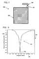
- FIG. 4is a first graph plotting the Return Loss Response of the unloaded loop antenna of the first antenna arrangement of FIG. 3 as a function of frequency in accordance with the principles of the present disclosure as described herein;
- FIG. 5is a schematic block diagram of another example antennae arrangement including a loaded loop antenna in accordance with the principles of the present disclosure as described herein;
- FIG. 6is a second graph plotting the Return Loss Response of the loaded loop antenna of the second antenna arrangement of FIG. 5 as a function of frequency in accordance with the principles of the present disclosure as described herein;
- FIG. 7is a schematic block diagram of a third antennae arrangement including an unbalanced antenna in accordance with the principles of the present disclosure as described herein;
- FIG. 8is a third graph plotting the Return Loss Response of the unbalanced antenna of the third antenna arrangement of FIG. 7 as a function of frequency in accordance with the principles of the present disclosure as described herein;
- FIG. 9is a schematic block diagram of a fourth example antenna arrangement including an unbalanced antenna capacitively coupled to a loaded loop antenna in accordance with the principles of the present disclosure as described herein;
- FIG. 10is a fourth graph plotting the Return Loss Response of the unbalanced antenna of the fourth antenna arrangement of FIG. 9 as a function of frequency in accordance with the principles of the present disclosure as described herein;
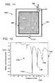
- FIG. 11is a schematic block diagram of a fifth example antenna arrangement including an unbalanced antenna decoupled from a loaded loop antenna in accordance with the principles of the present disclosure as described herein;
- FIG. 12is a fifth graph plotting the Return Loss Response of the unbalanced antenna of the fifth antenna arrangement of FIG. 11 as a function of frequency in accordance with the principles of the present disclosure as described herein;
- FIG. 13is a schematic block diagram of an implantable device including a loop antenna wound around a housing and entering the housing at a first port in accordance with the principles of the present disclosure as described herein;
- FIG. 14is a schematic block diagram of an implantable device including and a loop antenna having a sharp edge embedded within a dielectric material in accordance with the principles of the present disclosure as described herein;
- FIG. 15is a schematic block diagram of an implantable device including and a loop antenna and an unbalanced antenna having a sharp edge embedded within a dielectric material in accordance with the principles of the present disclosure as described herein;
- FIG. 16is a schematic block diagram of an implantable device including a loop antenna fully embedded within a dielectric material and wound around a housing in accordance with the principles of the present disclosure as described herein;
- FIG. 17is a schematic block diagram of an implantable device including a loop antenna wound around a housing with both the loop antenna and the housing being fully embedded within a dielectric material in accordance with the principles of the present disclosure as described herein;
- FIG. 18is a schematic block diagram of an implantable device including a loop antenna wound around a housing with the loop antenna being fully embedded within a dielectric material and the housing being partially embedded within the dielectric material in accordance with the principles of the present disclosure as described herein;
- FIG. 19is a schematic block diagram of a simple loop antenna arranged in free space (i.e., completely outside the three-layer structure of FIG. 20 ) in accordance with the principles of the present disclosure as described herein;
- FIG. 20is a schematic block diagram of a simple loop antenna arranged within an outer layer (and outside an insulating layer) of a three-layer structure in accordance with the principles of the present disclosure as described herein;
- FIG. 21is a schematic block diagram of a simple loop antenna having a first part arranged within an outer layer of the three-layer structure of FIG. 20 and a second part arranged within an insulating layer in accordance with the principles of the present disclosure as described herein;
- FIG. 22is a schematic block diagram of a simple loop antenna arranged completely within an insulating layer of the three-layer structure of FIG. 20 in accordance with the principles of the present disclosure as described herein;
- FIG. 23is a graph plotting the lowest dip of a Return Loss Response of each of the loop antenna arrangements shown in FIGS. 19-22 as a function of frequency in accordance with the principles of the present disclosure as described herein;
- FIG. 24is a schematic block diagram of an implantable device having an antenna arrangement including an array of antennae capacitively coupled to a loop antenna, the antenna arrangement being coupled to an inner housing in accordance with the principles of the present disclosure as described herein;
- FIG. 25is a perspective view of an implantable device having a loop antenna wrapped around an inner housing and capacitively coupled to a second antenna protruding from the inner housing in accordance with the principles of the present disclosure as described herein;
- FIG. 26is a front view of the implantable device of FIG. 25 in accordance with the principles of the present disclosure as described herein;
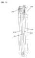
- FIG. 27is a side view of the implantable device of FIG. 25 in accordance with the principles of the present disclosure as described herein;
- FIG. 28is a perspective view of another implantable device having a loop antenna wrapped around an inner housing and moderately coupled to a second antenna protruding from the inner housing in accordance with the principles of the present disclosure as described herein;
- FIG. 29is a front view of the implantable device of FIG. 28 in accordance with the principles of the present disclosure as described herein;
- FIG. 30is a side view of the implantable device of FIG. 28 in accordance with the principles of the present disclosure as described herein;
- FIG. 31is a perspective view of an implantable device having a loop antenna wrapped around an inner housing and decoupled from a second antenna protruding from the inner housing in accordance with the principles of the present disclosure as described herein;
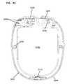
- FIG. 32is a front view of the implantable device of FIG. 31 in accordance with the principles of the present disclosure as described herein;
- FIG. 33is a side view of the implantable device of FIG. 31 in accordance with the principles of the present disclosure as described herein;
- FIG. 34is a schematic block diagram of an example implantable device including a loop antenna wound around a housing and configured in accordance with the principles of the present disclosure as described herein.
- the methods, devices and systems as described hereinare applicable to treating a wide variety of medical conditions, such as cardiac arrhythmias or other cardio-pulmonary conditions, pancreatitis, diabetes, incontinence, gastro-esophageal reflux disease (GERD), or obesity or other gastro-intestinal disorders.
- the methods, devices and systems as described hereinalso may be applicable to pain management, tissue ablation systems, implantable drug pumps (e.g., insulin pumps), and implantable condition monitoring devices.
- the disclosureprovides an implantable medical device comprising: an inner housing containing a processor and a communications circuit; a first antenna arrangement wrapped circumferentially around the inner housing, the first antenna arrangement having a first port at which the first antenna arrangement enters the inner housing, the first antenna arrangement being electrically coupled to the communications circuit via the first port, the first antenna arrangement including a loop antenna that is electrically coupled to the communications circuit via the first port; and a second antenna arrangement arranged external of the inner housing, the second antenna arrangement having a second port at which the second antenna arrangement enters the inner housing, the second antenna arrangement being capacitively coupled to the loop antenna; wherein the implantable medical device is configured for implantation within a body of a patient.
- Another aspect of the disclosureprovides a method for communicating with an implantable device, the method comprising: providing an implantable device including a loop antenna wound around an exterior of an inner housing containing a processor, a communications circuit, a rechargeable power source, and a switching circuit, the implantable device also including a second antenna capacitively coupled to the loop antenna; implanting the implantable device within the patient; transmitting a power signal to the implantable device to provide power to the rechargeable power source, the power signal having a first frequency; and transmitting a communication signal to the implantable device to provide data or commands to the communications circuit.
- the communications signalhas a second frequency that is higher than the first frequency.
- an antenna arrangementincludes an arrangement of one or more antennae. If the antenna arrangement includes multiple antennae, then each antenna in the arrangement may be capacitively coupled or decoupled from each of the other antennae.
- FIG. 1is a schematic block diagram of a therapy system 100 for treating a medical condition, such as obesity.
- the therapy system 100includes a sealed implantable device 105 , at least one therapy and/or diagnostic element 170 , and an external component 160 configured to communicate with the implantable device 105 via an implantable antenna arrangement 120 .
- the implantable device 105 and implantable antenna arrangement 120are adapted for implantation beneath the skin layer 130 of a patient to be treated.
- the implanatable deviceis hermetically sealed.
- the implantable device 105includes a housing 106 that provides a sealed enclosure in which circuitry of the implantable device may be housed.
- the housing 106contains a communications circuit (e.g., an RF module) 110 and a treatment module 115 .
- the housing 106provides electrical shielding for the RF module 110 and the treatment module 115 .
- the housing 106may provide a grounding plane for one or more antennae of the antenna arrangement 120 coupled to the implantable device 105 .
- the housing 106may be formed from one or more conductive materials (e.g., Titanium, Niobium, Platinum, Indium, stainless steel, MP35N alloys, or other biocompatible materials).
- the housing 106may be plated with a conductive material (e.g., Gold plated over Copper). In other embodiments, however, non-conductive layers may be added in or around all or part of the housing 106 as will be disclosed in greater detail herein.
- a conductive materiale.g., Gold plated over Copper
- the treatment module 115manages treatment of the patient.
- the treatment module 115is configured to communicate with the therapy element and/or diagnostic element 170 .
- the treatment module 115is configured to generate a therapy signal and to communicate (e.g., electrically) the therapy signal to the therapy element (e.g., lead electrodes) 170 to provide treatment to the patient.
- the treatment module 115obtains readings indicating a condition of the patient from a diagnostic device (e.g., a temperature sensor, an accelerometer, etc.).
- a diagnostic devicee.g., a temperature sensor, an accelerometer, etc.
- the therapy element 170provides electrical signals (e.g., pulses) to at least one area of the patient's body in accordance with the therapy signals generated by the treatment module 115 .
- the therapy element 170may include two or more electrical lead assemblies (not shown) that couple to nerves, muscles, organs, or other tissue of the patient.
- the electrical lead assemblycomprises a lead and one or more electrodes.
- the therapy and/or diagnostic element 170is arranged external to the hermetically sealed implantable device 105 . In another embodiment, the therapy and/or diagnostic element 170 is arranged within the hermetically sealed implantable device 105 .
- the therapy element 170up-regulates and/or down-regulates one or more nerves of a patient based on the therapy signals provided by the treatment module 115 .
- electrodesmay be individually placed on the anterior vagus nerve and posterior vagus nerve, respectively, of a patient.
- the placement of the electrodes on the vagus nervemay vary.
- the electrodeis placed below the innervation of the heart such as in sub diaphragmatic location. In other embodiments, however, fewer or greater electrodes can be placed on or near fewer or greater nerves.
- the therapy element 170may provide electrical signals directly to the patient's organs, such as the heart, lungs, and/or stomach, or to the patient's muscles, such as the sphincter muscle, or to other tissue of the patient.
- the external component 160includes circuitry for communicating with the implantable device 105 .
- communicationis transmitted through the skin 130 of the patient along a two-way signal path as indicated by double-headed arrow 150 .
- Example communication signalsinclude power signals, data signals, and command signals.
- the RF module 110controls when power signals, data signals, and/or command signals are radiated to and from the implantable device 105 within the near-field and/or the far-field.
- the external component 160can communicate with the implantable device 105 via bidirectional telemetry (e.g. via radiofrequency (RF) signals).
- the external component 160may provide power to the implantable device 105 via an RF link.
- treatment instructionsinclude treatment parameters, signal parameters, implantable device settings, treatment schedule, patient data, command signals, or other such signals may be communicated between the external component 160 and the implantable device 105 .
- the external component 160 shown in FIG. 1includes another antenna arrangement 165 that can send and receive RF signals.
- the implantable antenna arrangement 120may be implanted within the patient and coupled to the RF module 110 of the implantable device 105 .
- the implantable antenna arrangement 120is integral with the implantable device 105 .
- the implantable antenna arrangement 120serves to radiate (e.g., receive and transmit) signals from and to the antenna arrangement 165 of the external component 160 within the near-field and/or the far-field.
- the RF module 110includes a matching circuit that optimizes the impedance of the antenna arrangement 120 for a particular frequency.
- the external component 160 and the RF module 110can encode and decode information signals as bit streams by amplitude modulating, frequency modulating, or rectifying an RF carrier wave.
- the signals radiated between the antenna arrangements 165 , 120have a carrier frequency of about 6.78 MHz. In other embodiments, however, higher or lower carrier wave frequencies and/or rectification levels may be used and other modulation methods and levels may be used.
- the implantable device 105communicates with the external component 160 using load shifting.
- load shiftingcan be achieved by modification of the load induced on the external component 160 . This change in the load can be sensed by the inductively coupled external component 160 .
- the implantable device 105 and external component 160can communicate using other types of signals.
- the RF module 110 of the implantable device 105receives power from the external component 160 . In some embodiments, the RF module 110 distributes the power to the treatment module 115 to generate the therapy signals. In one such embodiment, the treatment module 115 may depend entirely upon power received from an external source (e.g., the external component 160 or another external power source). In another embodiment, an implantable power source 117 , such as a rechargeable battery, supplies the power to generate the therapy signals. In such an embodiment, the RF module 110 may distribute the power received from the external component 160 to the implantable power source 117 for recharging.
- an implantable power source 117such as a rechargeable battery
- the treatment module 115initiates the generation and transmission of therapy signals to the therapy elements 170 . In an embodiment, the treatment module 115 initiates therapy when powered by the implantable power source 117 . In other embodiments, however, the external component 160 triggers the treatment module 115 to begin generating therapy signals. After receiving initiation signals from the external component 160 , the treatment module 115 generates the therapy signals and transmits the therapy signals to the therapy elements 170 .
- the external component 160also can provide the instructions according to which the therapy signals are generated.
- Example parameters of therapy signalsmay include pulse-width, amplitude, frequency, ramping, duty cycle, treatment schedule, and other such parameters.
- the external component 160includes memory in which several predetermined programs/therapy schedules can be stored for transmission to the implantable device 105 .
- the external component 160also can enable a user to select a program/therapy schedule stored in memory for transmission to the implantable device 105 .
- the external component 160can provide treatment instructions with each initiation signal.
- each of the programs/therapy schedules stored on the external component 160can be adjusted by a physician to suit the individual needs of the patient.
- a computing devicee.g., a notebook computer, a personal computer, etc.
- a physiciancan use the computing device to program therapies into the external component 160 for either storage or transmission to the implantable device 105 .
- the implantable device 105also may include memory (not shown) in which treatment instructions and/or patient data can be stored.
- the implantable device 105can store therapy programs indicating what therapy should be delivered to the patient.
- the implantable device 105also can store patient data indicating how the patient utilized the therapy system 100 and/or reacted to the delivered therapy.
- the implantable device 105contains a rechargeable battery from which the implantable device 105 may draw power.
- FIG. 2is a schematic block diagram of another therapy system 100 ′ including an implantable device 105 ′, an external component 160 , and a therapy element 170 .
- the implantable device 105 ′includes at least one RF module 110 , a treatment module 115 , and an antenna arrangement 120 ′ including a first antenna arrangement 122 and a second antenna arrangement 124 .
- the first antenna arrangement 122includes a loop antenna.
- the second antenna arrangement 124includes an unbalanced antenna including, for example, an inverted-L antenna, a zigzag antenna, a helical antenna, a spiral antenna, a folded antenna, a serpentine antenna, or any other suitable antenna that is capacitively coupled to the first antenna arrangement 122 .
- the second antenna arrangement 124includes a loop antenna that is capacitively coupled to the first antenna arrangement 122 .
- one or more antennae of the second antenna arrangement 124may be decoupled from the antennae of the first antenna arrangement 122 .
- the first antenna arrangement 122receives power (see arrow 152 ) with which to operate the implantable device 105 ′ and/or to recharge the power source 117 .
- the second antenna arrangement 124receives and transmits communication signals containing information (e.g., therapy parameters, schedules, patient data, etc.) and/or command signals (see arrow 154 ) from and to the external component 160 .
- informatione.g., therapy parameters, schedules, patient data, etc.
- command signalssee arrow 154
- separating the functions of the antenna arrangements 122 , 124may allow for concurrent radiation of power and communication signals (e.g., commands and/or data). Separating the functions also may enable tuning each antenna arrangement 122 , 124 to better implement a particular function, such as communication range or charging efficiency.
- the first antenna arrangement 122also can receive and transmit information signals from and to the external component 160 .
- the second antenna arrangement 124may include an array of antennae (e.g., see FIG. 24 ). Each of the antennae in the antennae array may be capacitively coupled or decoupled to or from the first antenna arrangement 122 and/or each other antenna in the antennae array. As will be described in greater detail herein, the antennae of the array may be utilized to modify the direction, polarization, and/or gain of the information signals received and transmitted by the first antenna 122 . Providing diversified antennae within the implantable device 105 ′ also may enable tailoring of the RF signal to accommodate the location and/or orientation of the implantable device 105 ′ with respect to an external source. Additional antennae also may be utilized to locate the implantable device 105 ′ with respect to an external object, such as the external component 160 .
- an external objectsuch as the external component 160 .
- an implantable devicecomprises a first antenna arrangement wrapped circumferentially around the inner housing, the first antenna arrangement having a first port at which the first antenna arrangement enters the inner housing, the first antenna arrangement being electrically coupled to the communications circuit via the first port, the first antenna arrangement including a loop antenna that is electrically coupled to the communications circuit via the first port.
- the implantable devicealso may comprise a second antenna arrangement arranged external of the inner housing, the second antenna arrangement having a second port at which the second antenna arrangement enters the inner housing, the second antenna arrangement being capacitively coupled to the loop antenna.
- the first and second antenna arrangementstransmit at different frequencies.
- FIGS. 3-12different antenna arrangements and configurations may be utilized in the implantable devices disclosed herein, e.g., as implantable antenna arrangement 120 .
- the radiation capabilities of different types of antenna arrangementsare shown relative to one another.
- five different types of antenna arrangementsare presented and a numerically simulated Return Loss Response for each in free space is shown.
- the antenna arrangements in FIGS. 3-12are not coupled to implantable devices. Rather, the numerical simulations are provided for the antenna arrangements positioned in free space in order to compare the radiation capabilities of the different antenna arrangements.
- the Simulated Return Loss Responseis defined as a ratio of reflected signal power over input signal power.
- the Simulated Return Loss Response for each antenna arrangementprovides information about the resonant frequencies, transmission range, radiation efficiency, and the number of resonant frequencies of the antenna arrangement. For example, dips in the Simulated Return Loss Response generally correspond with resonant frequencies of the antenna arrangement. Furthermore, the amplitude of the dips in the Simulated Return Loss Response generally corresponds with the efficiency (and hence power) of the antenna arrangement.
- the Simulated Return Loss Responseprovides for a selection of different antenna arrangements depending on the requirements for a particular therapy system. For example, in some embodiments, it is desirable to transmit a power signal and a communication signal concurrently. In other embodiments, it may be desirable to eliminate a matching circuit in the device. In other embodiments, it may be desirable to eliminate resonant frequencies from an antenna arrangement.
- FIG. 3is a schematic block diagram of a first example antenna arrangement 200 that may be used in the implantable devices disclosed herein.
- the antenna arrangement 200includes a loop antenna 210 having a first port 211 .
- the loop antenna 210 of antenna arrangement 200may be utilized with an implantable device as an implantable antenna (e.g., antenna 120 of FIGS. 1 and 2 ).
- the loop antenna 210may enable magnetic coupling of an implantable device (e.g., implantable device 105 of FIG. 1 ) to an external component (e.g., external component 160 of FIG. 1 ) for power and/or communication (e.g., command signals and/or data signals) transference.
- an implantable devicee.g., implantable device 105 of FIG. 1
- an external componente.g., external component 160 of FIG. 1
- power and/or communicatione.g., command signals and/or data signals
- FIG. 4is a first graph 300 plotting a Simulated Return Loss Response 330 of the first port 211 of the first antenna arrangement 200 as a function of frequency.
- the results plotted in the first graph 300were obtained using a mathematical model (i.e., numerical simulation) of a loop antenna in free space separate from an implantable device. Accordingly, the first graph 300 (i.e., as well as the graphs shown in FIGS. 6 , 8 , 10 , and 12 ) are provided to disclose the relative RF radiation capability of each antenna arrangement with respect to each other and not to describe the actual radiation capability of the implantable system.
- the first graph 300includes a first axis 310 representing the Return Loss Response (dB) of the loop antenna 210 as measured at the first port 211 .
- the first axis 310ranges from about ⁇ 7 decibels (dB) to about 1 dB.
- the first graph 300also includes a second axis 320 representing the frequency of the loop antenna 210 .
- the second axis 320ranges from about 0 gigahertz (GHz) to about 3 GHz.
- the Return Loss Response 330has a first dip 332 of about ⁇ 6.5 dB at a frequency of approximately 0.45 GHz. Additional dips (e.g., see 334 ) occur at higher signal frequencies.
- This configurationmay be desirable if a low resonant frequency and/or a lower amplitude, high resonant frequency is desired.
- the amplitude of the dips in FIG. 4tends to be lower than in other configurations described herein, the radiation capability of this configuration is lesser than some of the other configurations.
- FIG. 5is a schematic block diagram of a second example antenna arrangement 400 including a loaded loop antenna that may be used in the implantable devices disclosed herein.
- the second antenna arrangement 400includes the loop antenna 210 of FIG. 1 and a floating conductive plate 220 providing a loading effect on the loop antenna 210 .
- the effects of the conductive plate 220can represent the loading effects of a conductive housing on an antenna arrangement in an implantable device.
- the loop antenna 210has the first port 211 and is wound one or more times around the plate 220 without contacting the plate 220 .
- the plate 220affects the Return Loss Response of the loop antenna 210 (e.g., through “the loading effect”) as shown in FIG. 6 .
- the effects of the housing 106 of the implantable device 105 on the implantable antenna 120(see FIG. 1 ) mimic these effects of the floating conductive plate 220 on the loop antenna 210 .
- FIG. 6is a second graph 500 plotting the Return Loss Response 530 of the first port 211 of the second antenna arrangement 400 as a function of frequency.
- the second graph 500is provided to aid in comparing the radiation capability of the loaded-loop antenna arrangement 400 to other antenna arrangement (e.g., the unloaded loop antenna arrangement 200 of FIG. 3 ) disclosed herein.
- the results plotted in the second graph 500were obtained using a mathematical model (i.e., numerical simulation) of a loaded loop antenna in free space separate from an implantable device.
- the second graph 500includes a first axis 510 representing the Return Loss Response at the first port 211 of the loaded loop antenna arrangement 400 .
- the first axis 510ranges from about ⁇ 20 dB to about 2 dB.
- the second graph 500also includes a second axis 520 representing the frequency of the loaded loop antenna arrangement 400 .
- the second axis 520ranges from about 0 GHz to about 3 GHz.
- the Return Loss Response 530has a dip 532 of about ⁇ 19 dB at a frequency of approximately 0.5 GHz. Additional dips (e.g., see 534 ) occur at higher signal frequencies.
- the amplitude of the dips (e.g., dips 532 , 534 ) in the Return Loss Response 530has increased.
- the dips in the Simulated Return Loss Response 530did not shift significantly on the second axis 520 . Accordingly, the frequency (i.e., or frequencies) at which the antenna arrangement resonates is not significantly affected.
- FIG. 7is a schematic block diagram of a third antenna arrangement 600 including an unbalanced antenna 230 capacitively coupled to a conductive plate, such as conductive plate 220 of FIG. 5 , that may be used in the implantable devices disclosed herein.
- the unbalanced antenna 230has a port 231 .
- the unbalanced antenna 230includes an inverted-L antenna arranged adjacent to the conductive plate 220 .
- the unbalanced antenna 230may include any unbalanced antenna.
- Non-limiting examples of a suitable unbalanced antenna 230include a helical antenna, a spiral antenna, a zigzag antenna, a folded antenna, and a serpentine antenna.
- FIG. 8is a third graph 700 plotting the Return Loss Response 730 at the port 231 of the third antenna arrangement 600 as a function of frequency.
- the third graph 700is provided to aid in comparing the radiation capability of the antenna arrangement 600 to other antenna arrangements (e.g., the loaded loop antenna arrangement 400 of FIG. 5 ) disclosed herein.
- the results plotted in the third graph 700were obtained using a mathematical model (i.e., numerical simulation) of an inverted-L antenna arranged in free space separate from an implantable device.
- the third graph 700includes a first axis 710 representing the Return Loss Response at the port 231 of the third antenna arrangement 600 .
- the first axis 710ranges from about ⁇ 22.5 dB to about 0 dB.
- the third graph 700also includes a second axis 720 representing the frequency of the third antenna arrangement 600 .
- the second axis 720ranges from about 0 GHz to about 3 GHz.
- the Return Loss Response 730 at the port 231has a dip 732 of about ⁇ 22 dB at a frequency of approximately 1.4 GHz.
- the third antenna arrangement 600 including the unbalanced antenna 230radiates more effectively at a higher operating frequency (i.e., has a higher resonant frequency) than the loop antenna arrangements 200 , 400 disclosed above. Accordingly, the third antenna arrangement 600 is capable of transmitting over a greater distance.
- FIG. 9is a schematic block diagram of an example antenna arrangement 800 that may be used in the implantable devices disclosed herein.
- the antenna arrangement 800capacitively couples the loaded loop antenna 400 of FIG. 5 with the unbalanced antenna 600 of FIG. 7 .
- the fourth antenna arrangement 800includes the loop antenna 210 , the conductive plate 220 , and the unbalanced antenna 230 disclosed herein.
- the unbalanced antenna 230is an inverted-L antenna. In other embodiments, however, the unbalanced antenna 230 may includes any suitable unbalanced antenna arranged to capacitively couple to the plate 220 and to the loop antenna 210 .
- FIG. 10is a fourth graph 900 plotting the Simulated Return Loss Response 930 at the first port 211 of the loop antenna 210 of the fourth antenna arrangement 800 as a function of frequency. Accordingly, the Simulated Return Loss Response 930 indicates how capacitively coupling the unbalanced antenna to the loop antenna affects the radiation capability of the loop antenna 210 .
- the fourth graph 900is provided to aid in comparing the radiation capability of the fourth antenna arrangement 800 to other antenna arrangement (e.g., the loaded loop antenna arrangement 400 of FIG. 5 and/or the unbalanced antenna arrangement 600 of FIG. 7 ) disclosed herein.
- the results plotted in the fourth graph 900were obtained using a mathematical model (i.e., numerical simulation) of an inverted-L antenna capacitively coupled to a loaded loop antenna in free space separate from a communications circuit or other part of an implantable device.
- the fourth graph 900includes a first axis 910 representing the Return Loss Response at port 231 of the unbalanced antenna 230 of the fourth antenna arrangement 800 .
- the first axis 910ranges from about ⁇ 22.5 dB to about 0 dB.
- the fourth graph 900also includes a second axis 920 representing the frequency of the fourth antenna arrangement 800 .
- the second axis 920ranges from about 0 GHz to about 3 GHz.
- the Return Loss Response 930has a first dip 932 of about ⁇ 16 dB at a frequency of approximately 0.4 GHz, a second dip 934 of about ⁇ 19 dB at about 0.75 GHz, a third dip 936 of about ⁇ 20 dB at about 1.2 GHz, and a fourth dip 938 of about ⁇ 19.5 dB at about 1.5 GHz. Additional dips occur at higher signal frequencies (e.g., see dip 939 ).
- a comparison of the second, third, and fourth graphs 500 , 700 , 900 , respectively,indicates that capacitively coupling an unbalanced antenna (e.g., unbalanced antenna 230 of FIG. 7 ) to a loaded loop antenna (e.g., loaded loop antenna 210 of FIG. 5 ) yields an antenna arrangement with a greater aperture than either antenna individually.
- the resulting antenna arrangementhas an increased radiation efficiency and increased resonance.
- the larger dips in the Simulated Return Loss Response at resonant frequencies in FIG. 10also indicate the antenna arrangement may utilize less power to transmit over a given range or may transmit farther for a given power level.
- increasing the aperture of the antennamay enable communication at MICS (Medical Implant Communications Service) frequency levels (e.g., about 0.4 GHz) and WMT (Wireless Medical Telemetry) frequencies levels (about 1.4 GHz) without a matching circuit.
- MICSMedical Implant Communications Service
- WMTWireless Medical Telemetry frequencies levels
- Eliminating the matching circuit from the implantable devicewould enable the implantable device to be smaller and manufactured at lower cost. Eliminating the matching circuit also may enhance the reliability of the implantable device by reducing the number of parts.
- capacitively coupling an unbalanced antenna (e.g., unbalanced antenna 230 of FIG. 7 ) to a loaded loop antenna (e.g., loaded loop antenna 210 of FIG. 5 )yields an antenna arrangement having an increased number of resonant frequencies.
- the capactively coupled antenna arrangement 800 of FIG. 9has a resonant frequency dip 932 at approximately 0.4 GHz and another resonant frequency dip 938 at about 1.5 GHz (see FIG. 10 ).
- the antenna arrangement 800could be configured to have a resonant frequency of about 6.7 MHz.
- Increasing the number of resonant frequenciesmay increase the number of signals that may be obtained by the antenna arrangement.
- the antenna arrangementin one embodiment, a capacitively coupled antenna arrangement may be able to radiate power and communication signals.
- increasing the number of resonant frequenciesmay increase the number of signals that may be obtained concurrently.
- the antenna arrangementmay include a first antenna (e.g., loop antenna 210 ) configured to radiate power and a second antenna (e.g., unbalanced antenna 230 ) configured to radiate communication signals.
- the first antennamay receive power (e.g., from about zero to about three watts) from one or more external components (e.g., see external component 160 of FIG. 2 ) and the second antenna may receive and transmit data (e.g., therapy parameters, treatment schedules, patient use data, treatment results, etc.) and/or commands (e.g., begin treatment, utilize a given treatment schedule, etc.) from and to the external components.
- datae.g., therapy parameters, treatment schedules, patient use data, treatment results, etc.
- commandse.g., begin treatment, utilize a given treatment schedule, etc.
- the received poweris used to recharge an internal power source, such as rechargeable battery 117 of FIGS. 1 and 2 .
- an internal power sourcesuch as rechargeable battery 117 of FIGS. 1 and 2 .
- a fewer or greater number of antennaemay be utilized to receive and transmit communication signals and/or power signals.
- the power and communication signalsmay be radiated concurrently, thereby enhancing the efficiency of the implantable device.
- each antennamay be tuned to optimize performance of its assigned task.
- the first antennamay be a loop antenna configured to radiate high amplitude RF signals at lower frequencies (e.g., over shorter distances) and the second antenna may be an unbalanced antenna configured to radiate RF signals at higher frequencies (e.g., over longer distances).
- powermay be transferred within the near-field of the antenna arrangement and communication signals may be communicated within the far-field of the antenna arrangement.
- FIG. 11is a schematic block diagram of a fifth example antenna arrangement 1000 that may be used in the implantable devices disclosed herein.
- the fifth antenna arrangement 1000includes a loop antenna 210 loaded with a conductive plate 220 and another unbalanced antenna 235 . Both antennae 210 , 235 have ports 211 , 236 , respectively, at which Return Loss Response may be measured.
- the unbalanced antenna 235 of the fifth antenna arrangement 1000is decoupled from the loop antenna 210 (e.g., arranged perpendicular to the loop antenna 210 ).
- the unbalanced antenna 235is a vertical monopole antenna. In other embodiments, however, the unbalanced antenna 235 may include any suitable antenna arranged to not couple to the loop antenna 210 .
- FIG. 12is a fifth graph 1100 plotting the Return Loss Response 1130 at the port 236 of the decoupled monopole antenna 235 of the fifth antenna arrangement 1000 as a function of frequency.
- the fifth graph 1100is provided to aid in comparing the radiation capability of the decoupled antenna arrangement 1000 to other antenna arrangement (e.g., the antenna arrangement 800 of FIG. 9 ) disclosed herein.
- the results plotted in the fifth graph 1100were obtained using a mathematical model (i.e., numerical simulation) of a monopole antenna decoupled from a loaded loop antenna in free space separate from an implantable device.
- the fifth graph 1100includes a first axis 1110 representing the Return Loss Response at the port 236 of the unbalanced antenna 235 of the fifth antenna arrangement 1000 .
- the first axis 1110ranges from about ⁇ 25 dB to about 0 dB.
- the fifth graph 1100also includes a second axis 1120 representing the frequency of the fifth antenna arrangement 1000 .
- the second axis 1120ranges from about 0 GHz to about 3 GHz.
- the Return Loss Response 1130 of the decoupled antenna arrangement 1000has a first dip 1132 of about ⁇ 24 dB at a frequency of approximately 1.7 GHz, a second dip 1134 of about ⁇ 18 dB at about 2.1 GHz, and a third dip 1136 of about ⁇ 13 dB at about 2.5 GHz.
- decoupling an unbalanced antenna (e.g., antenna 235 ) from a loaded loop antenna (e.g., loaded loop antenna 210 )shifts the resonant frequencies of the antenna arrangement to higher frequencies (e.g., compare FIGS. 6 , 8 , and 12 ).
- Decoupling the antennaealso may decrease the number of resonant frequencies.
- decreasing the number of resonant frequenciesmay mitigate interference between different antennae.
- decoupling the antennaemay enable simultaneous radiation of power signals and communication signals by different antennae without interference.
- the radiation capability of different antenna configurationsmay be modified by partially or fully embedding one or more of the antennae in an insulating layer of dielectric material.
- insulating dielectric materialsinclude biocompatible materials, such as biocompatible plastics (e.g., silicone rubber, polysulphone, TECOTHANE® offered by Lubrizol Advanced Materials, Inc. of Cleveland, Ohio, etc).
- FIGS. 13-18are schematic block diagrams illustrating different embodiments of an implantable device 1200 A, 1200 B, 1200 C, 1200 D, 1200 E, 1200 F, respectively, having an antenna arrangement including a loop antenna 1210 loaded with a conductive medium 1220 .
- the conductive medium 1220includes the hermetically sealed inner housing of an implantable device that contains the circuitry of the implantable device. In other embodiments, however, the conductive medium 1220 may include any conductive surface.
- the loaded loop antenna 1210enters the inner housing 1220 and couples to components within the housing 1220 via an antenna port 1211 .
- antenna arrangement of the implantable device 1200 Ais fully exposed (i.e., no part of the antenna arrangement is enclosed within a dielectric medium). Accordingly, antenna arrangement may be arranged in contact with surrounding tissue when implanted within a patient. Non-limiting examples of surrounding tissue may include muscle, fat, nerve, or skin layers of the patient. In the example shown, the antenna arrangement includes a loaded loop antenna 210 . In other embodiments, however, the antenna arrangement may include one or more balanced and/or unbalanced antennae.
- the dielectric constant of the surrounding tissueincreases the aperture of the exposed antenna.
- Increasing the aperture of the antennaenables a smaller antenna to be utilized.
- radiating the loop antenna 1210 at lower frequenciesmitigates radiation efficiency concerns due to return loss, since human tissue tends to be low loss at these lower frequencies.
- the antenna arrangementmay cost less and/or be easier to manufacture without a dielectric layer.
- sharp edges of the antenna arrangements of the implantable devices 1200 B, 1200 Cmay be partially embedded within an insulating dielectric medium.
- the antenna arrangementincludes a loop antenna 1210 having a first sharp edge 1213 that is embedded within a dielectric layer 1240 .
- the antenna arrangementincludes a loop antenna 1210 having sharp corners 1217 that are embedded within a first dielectric layer 1242 and an unbalanced antenna 1230 having a sharp edge 1233 that is embedded within a second dielectric layer 1244 .
- the antenna arrangementmay include a greater or fewer number of balanced and/or unbalanced antennae.
- Portions of the loaded loop antenna 1210still may be arranged in contact with surrounding tissue when implanted, thereby increasing the aperture of the antenna arrangements.
- insulating the sharp edges of the antenna arrangementsmay inhibit burns or other harm to a patient in which the antenna arrangement is implanted when the patient is scanned with a Magnetic Resonance Image (MRI) machine. If the sharp edges are left exposed, current induced by the magnetic field that is generated by the MRI machine may build up at these edges and burn the surrounding tissue.
- the low dielectric mediume.g., dielectric layers 1240 , 1242 , 1244 ) may inhibit accumulation of a high current density at the antenna edges from the effects of the magnetic field created by the MRI machine.
- the antenna arrangement of the implantable device 1200 Dis fully embedded within a layer of dielectric medium 1240 .
- the antenna arrangementincludes the loaded loop antenna 210 .
- the antenna arrangementmay include one or more balanced and/or unbalanced antennae.
- the implantable device 1200 Dmay contact different types of surrounding tissue (e.g., fat, muscle, nerves, etc.). Each type of surrounding tissue may have different dielectric constants.
- Embedding the antenna arrangement in the layer of dielectric mediuminsulates the antenna arrangement from effects of the dielectric constant of the surrounding medium. Accordingly, insulating the antenna arrangement in the dielectric material advantageously may enhance repeatability of performance by providing surrounding media (e.g., the dielectric layer 1240 ) having a consistent dielectric constant. Furthermore, when operating at higher frequencies (e.g., about 1.4 GHz), human tissue tends to be lossy (i.e., higher frequency signals tend to degrade as they travels through human tissue). Accordingly, insulating the antenna arrangement from the surrounding tissue may enhance the radiation efficiency of the antenna arrangement at higher frequencies. Moreover, if the dielectric layer is formed from a biocompatible material, then embedding the antenna arrangement within the dielectric layer may enhance the biocompatibility of the antenna arrangement.
- the dielectric layer 1240extends over the inner housing 1220 as well as the antenna arrangement (e.g., loaded loop antenna 1210 ) of the fifth implantable device 1200 E.
- embedding the inner housing 1220 within the dielectric layer 1240may increase the aperture of the antenna arrangement.
- embedding the inner housing 1220 that loads the loop antenna 1210may increase the aperture of the loop antenna 1210 by inhibiting the surface current on the periphery of the inner housing 1220 .
- embedding the inner housing 1220 within the dielectric layer 1240also may improve the biocompatibility of the implantable device 1220 .
- a first dielectric layer 1240extends over the antenna arrangement of the sixth implantable device 1200 F and a second dielectric layer 1245 partially embeds the inner housing 1220 .
- the antenna arrangementincludes a loaded loop antenna 1210 .
- the antenna arrangementmay include one or more balanced and/or unbalanced antennae. Partially embedding the inner housing 1220 within a dielectric layer may increase the aperture of the antenna arrangement.
- the section of the inner housing 1220 adjacent the port of the antenna arrangemente.g., port 1211 of the loaded loop antenna 1210
- exposed portions of the inner housing 1220may be used to provide treatment to the patient (e.g., as an electrode).
- Implantation environments for the antenna arrangementtend to vary by patient and even within the same patient.
- the dielectric constant of tissue surrounding an antenna arrangement implanted within the patientmay vary over the surface area of the antenna arrangement (e.g., when a first portion of the antenna arrangement contacts a nerve and a second portion of the antenna arrangement contacts muscle).
- the simulationis directed to a simple loop antenna 1310 arranged within a simplified implantation environment represented by a three-layer structure 1300 (see FIGS. 19-22 ).
- the three-layer structure 1300includes an inner layer 1340 having a first dielectric constant ⁇ 1 arranged between two outer layers 1360 , each of which have a second dielectric constant ⁇ 2 .
- the insulating layer 1340represents a layer of dielectric medium (e.g., the dielectric layer 1240 shown in FIGS. 14-18 ) and the outer layers 1360 represent human tissue surrounding the implantable device. Accordingly, the first dielectric constant ⁇ 1 of the inner layer 1340 is less than the second dielectric constant ⁇ 2 of the outer layers 1360 .
- a thickness H of about 10 mm and a dielectric constant ⁇ 1 of about 1were selected for the inner layer 1340 and a thickness T of about 150 mm and a dielectric constant ⁇ 2 of about 10 were selected for each of the outer layers 1360 .
- These measurementsdo not necessarily represent preferred dimensions and properties of the antenna arrangement or of the implantation environment. Rather, these measurements provide a simple model from which a numerical simulation may be computed to facilitate explanation and testing of the concept.
- the outer layers 1360may have different dielectric constants and/or thicknesses from one another.
- FIG. 19is a schematic block diagram of the loop antenna 1310 arranged within free space (i.e., completely outside the three-layer structure 1300 ). Accordingly, the loop antenna 1310 represents an implantable device having an antenna fully exposed to free space (e.g., air). For example, the loop antenna 1310 of FIG. 19 may represent an antenna arrangement of an implantable device before implantation.
- FIG. 20is a schematic block diagram of the loop antenna 1310 arranged within one of the outer layers 1360 of the three-layer structure 1300 and outside the inner layer 1340 .
- the loop antenna 1310represents an implantable device having an antenna arrangement fully exposed to the surrounding tissue of the patient.
- the loop antenna 1310 of FIG. 20may represent the loaded loop antenna 1210 of FIG. 13 , which is not insulated within an outer layer of a dielectric medium, after implantation.
- FIG. 21is a schematic block diagram of the loop antenna 1310 having a first part 1312 arranged within one of the outer layers 1360 and a second part 1314 arranged within the inner layer 1340 .
- the loop antenna 1310represents an implantable device having an antenna partially embedded within a dielectric medium and partially exposed to the surrounding tissue of the patient.
- the loop antenna 1310 of FIG. 21may represent the loaded loop antenna 1210 of FIG. 14 , which is partially insulated within a layer 1240 of a dielectric medium, after implantation.
- FIG. 22is a schematic block diagram of the loop antenna 1310 arranged completely within the inner layer 1340 .
- the loop antenna 1310represents an implantable device having an antenna fully embedded within an insulating layer of dielectric medium.
- the loop antenna 1310 of FIG. 22may represent the loaded loop antenna 1210 of FIG. 16 , which is fully insulated within a layer 1240 of a dielectric medium, after implantation.
- FIG. 23is a graph plotting the lowest dip of the Return Loss Response of the loop antenna 1310 for each arrangement shown in FIGS. 19-22 as a function of frequency.
- the graph 1500has a first axis 1510 representing Return Loss Response (dB) and a second axis 1520 representing frequency.
- the first axis 1510ranges from about ⁇ 30 dB to about 3 dB and the second axis 1520 ranges from about 0.1 GHz to about 0.5 GHz.
- symbols including circles, triangles, and diamondshave been added to the Return Loss Response curves of the graph 1500 to distinguish the different curves. These symbols do not correspond with actual data points, but rather serve only to differentiate the Return Loss Response curves.
- the Return Loss Response 1560 of the loop antenna arranged in free spaceis depicted by the unembellished solid curve.
- the Return Loss Response 1560 of this arrangementprovides a base reading to which the other Return Loss Responses may be compared.
- the Return Loss Response 1530 of the exposed loop antenna 1310 of FIG. 20is depicted by the diamond-dotted curve.
- the Return Loss Response 1540 of the partially insulated loop antenna 1310 of FIG. 21is depicted by the circle-dotted curve.
- the Return Loss Response 1550 of the fully insulated loop antenna 1310 of FIG. 22is depicted by the triangle-dotted curve.
- the lowest resonant frequency of the loop antenna (unembellished curve) arranged in free spaceis about 0.45 GHz with a return loss response 1560 of about ⁇ 6 dB.
- the lowest resonant frequency of the exposed loop antenna (diamonds)is about 0.19 GHz with a return loss response 1530 of about ⁇ 16 dB.
- the lowest resonant frequency of the partially embedded loop antenna (circles)is about 0.26 GHz with a return loss response 1540 of about ⁇ 27 dB.
- the lowest resonant frequency of the fully embedded loop antenna (triangles)is about 0.28 GHz with a return loss response 1550 of about ⁇ 19 dB.
- the graph 1500indicates implanting an exposed loop antenna 1310 ( FIG. 20 ) within human tissue lowers the resonant frequency and increases the radiation capability of the antenna arrangement (as compared to the antenna 1310 arranged in free space- FIG. 19 ).
- partially embedding the loop antenna 1310 within an insulating layer of dielectric mediummay shift the resonant frequency of the antenna to a higher frequency (compare curves 1530 and 1540 ).
- Fully embedding the loop antenna 1310 within the insulating layer of dielectric mediummay further shift the resonant frequency of the antenna (compare curves 1540 and 1550 ).
- FIG. 34is a schematic block diagram of an example implantable device 3400 including a loop antenna 3410 wound around a housing 3420 .
- the loop antenna 3410is wound around the housing 3420 only about once.
- the loop antenna 3410has a length of at least ⁇ , wherein ⁇ is the effective wavelength for far-field data communications.
- the loop antenna 3410is wound around the housing 3420 multiple times.
- the loop antenna 3410may be wound around the housing a sufficient number of times to have the antenna effective in near-field power transfer and/or communications.
- the implantable device 3400does not include a matching circuit.
- the loop antenna 3410may be partially or fully embedded within a dielectric layer. In another embodiment, the loop antenna 3410 may be fully exposed to the environment in which the implantable device 3400 is arranged. In another embodiment, the housing 3420 may be partially or fully embedded in a dielectric material. In another embodiment, the housing 3420 may be fully exposed.
- the loop antenna 3410is configured to receive power and to deliver the received power to circuitry within the housing 3420 .
- the loop antenna 3410is configured to resonate when receiving and transmitting a low frequency signal (e.g., around 6.73 MHz).
- the loop antenna 3410may deliver current induced by the received signal to a rechargeable power source 3424 within the housing 3420 .
- the loop antenna 3410is configured to resonate when receiving and transmitting a higher frequency signal (e.g., around 402-405 MHz).
- a higher frequency signale.g., around 402-405 MHz.
- the loop antennaappears electrically larger than when the loop antenna 3410 resonates at lower frequencies. Accordingly, the loop antenna 3410 may receive and send far-field signals.
- the loop antenna 3410may deliver current induced by the received signal to a communications circuit (e.g., a MICS communications circuit) 3426 within the housing 3420 .
- the loop antenna 3410also may receive power from the rechargeable power source 3424 and a data or command signal from the communications circuit 3426 and transmit the data or command signal using the received power.
- the loop antenna 3410is configured to resonate at multiple frequencies.
- the housing 3420 of the implantable devicemay include one or more switching circuits 3422 configured to receive current induced on the loop antenna 3410 when a signal is received.
- the switching circuit 3422determines the type of signal received (e.g., based on the frequency) and may provide power to an appropriate circuit within the housing 3420 based on the type of signal received.
- the switching circuit 3422is electrically coupled to the rechargeable power source 3424 and the communications circuit 3426 within the housing 3420 .
- the switching circuit 3422may determine whether to forward a signal received at the loop antenna 3410 to the power source 3424 for recharging or to the communications circuit 3426 for analysis.
- the switching circuit 3422may be electrically coupled to multiple communication circuits within the housing 3420 . In such an embodiment, the switching circuit 3422 may determine the appropriate communication circuit to which to forward the received signal.
- additional circuitrymay be provided within the housing 3420 and coupled to the switching circuit 3422 to provide additional functionality to the implantable device 3400 .
- the switching circuit 3422may direct power to the appropriate circuitry (e.g., based on the frequency of the received signal, based on instructions contained within the signal, etc.).
- inductive coupling between the loop antenna 3410 and one or more unbalanced antennaeincreases the number of resonant frequencies of the loop antenna 3410 . Accordingly, such inductive coupling may increase the range of applications capable of being performed by the implantable device 3400 .
- FIG. 24is a schematic block diagram of an example embodiment of an implantable device 1600 including an inner housing 1620 coupled to an antennae arrangement 1650 .
- the inner housing 1620may contain an RF module and a treatment module as disclosed above with reference to FIGS. 1 and 2 .
- the antenna arrangement 1650includes a loop antenna 1610 coupled to an array 1660 of antennae that may include any combination of balanced and unbalanced antennae.
- the array 1660includes antennae 1631 - 1639 coupled in series to the loop antenna 1610 .
- the antennae array 1660may enhance the flexibility and utility of the implantable device by providing radiation pattern diversity, spatial diversity, and/or polarization diversity.
- each antenna within the antennae array 1660may be tuned to resonate at a unique resonant frequency, thereby providing radiation pattern diversity.
- Different types of signalse.g., power and communication
- Spatial diversity of the antennae within the antennae array 1660may enable an external component to identify a location of the implantable device.
- Polarization diversitymay enhance coupling flexibility of the implantable device by reducing or removing dependencies of antenna orientation or antenna performance.
- two or more antennae of the array 1660may be capacitively coupled to one another to increase the aperture of the antenna arrangement.
- at least one of the antennae 1631 - 1639 of the antennae array 1660is an unbalanced antenna.
- one or more antennae of the array 1660may be decoupled from the loop antenna 1610 to inhibit interference with radiation from other antennae, other components, and/or other devices.
- the implantable device 1600also may include an optional insulating layer 1640 .
- the insulating layer 1640may partially or completely surround the antennae arrangement 1650 .
- the loop antenna 1610 and six of the additional antennae 1631 - 1636 of the array 1660are fully embedded within the insulating layer 1640 .
- Antennae 1637 and 1639 of the array 1660are partially embedded within the insulating layer 1640 and antenna 1638 is fully exposed to any surrounding medium (e.g., air, tissue, etc.).
- FIGS. 25-27illustrate a first example embodiment of an implantable device 2000 including a loop antenna 2010 wrapped around an inner housing 2020 containing components configured to implement telemetry and treatment, such as RF module 110 , a treatment module 115 , and a rechargeable battery 117 of FIGS. 1 and 2 .
- the loop antenna 2010couples to the circuitry via antenna port 2015 defined in the inner housing 2020 .
- the loop antenna 2010may be wrapped once around a perimeter of the inner housing 2020 . In another embodiment, the loop antenna 2010 may be wrapped about only a portion of the perimeter. In other embodiments, however, the loop antenna 2010 may be wound around the perimeter of the inner housing 2020 multiple times. In the example shown, the loop antenna 2010 is wrapped around the inner housing 2020 about four times (see windings 2012 , 2014 , 2016 , 2018 of FIG. 27 ).
- the loop antenna 2010may be wrapped around the inner housing 2020 in a helical pattern (e.g., see FIGS. 25 and 27 ). In another embodiment, the loop antenna 2010 may be wrapped about the inner housing 2020 in a spiral pattern.
- a helical winding patternallows for a smaller circumference than a spiral winding pattern.
- a spiral winding patternallows for a thinner form factor than a helical winding pattern.
- the loop antenna 2010may include sections wound in a spiral shape and other sections wound in a helix shape.
- the spiral shaped sectionsmay facilitate routing the loop antenna 2010 around lead sockets of the implantable device 2000 and the helical-shaped sections may be wound around the rest of the implantable device 2000 . Accordingly, the antenna configuration for each implantable device may be selected based on the intended implantation site and/or the intended function.
- a first unbalanced antenna 2030may be capacitively coupled to the loop antenna 2010 .
- the first unbalanced antenna 2030includes an inverted-L antenna.
- the first unbalanced antenna 2030includes a first section 2032 extending outwardly from the inner housing 2020 and wrapping around the loop antenna 2010 .
- the first unbalanced antenna 2030also includes a second section 2034 having a generally planar surface extending substantially parallel to the coils of the loop antenna 2010 .
- the first unbalanced antenna 2030may include any unbalanced antenna (e.g., a zigzag antenna, a helical antenna, a spiral antenna, a folded antenna, a serpentine antenna, or any other suitable antenna).
- the loop antenna 2010 and the unbalanced antenna 2030are fully enclosed within (i.e., fully insulated by) an outer layer 2040 of a dielectric material.
- the outer layer 2040may enclose only one of these antennae 2010 , 2030 .
- portions of one or both antennae 2010 , 2030may be enclosed within (i.e., partially insulated by) the outer layer 2040 .
- the antennae 2010 , 2030may be exposed (i.e., neither antenna may be enclosed within the outer layer 2040 ).
- Therapy ports 2060for receiving therapy elements, such as therapy elements 170 of FIGS. 1 and 2 , also may be defined in the outer layer 2040 .
- the therapy ports 2060are configured to accept connectors for therapy elements (e.g., lead connectors) in order to form an electrical connection between the therapy elements and components contained in the inner housing 2020 (e.g., the treatment module and a rechargeable battery).
- the outer layer 2040defines suture passages 2048 by which the implantable device 2000 may be secured in position within the patient.
- the outer layer 2040defines three suture passages 2048 extending through the implantable device 2000 .
- FIGS. 28-30illustrate a second example embodiment of an implantable device 2100 including a loop antenna 2110 wrapped around an inner housing 2120 containing treatment components, such as RF module 110 , treatment module 115 , and rechargeable battery 117 of FIGS. 1 and 2 .
- the loop antenna 2110couples to the RF module and the treatment module via antenna port 2115 defined in the inner housing 2120 .
- the loop antenna 2110may be wrapped around a perimeter of the inner housing 2120 .
- the loop antenna 2110is wrapped around the inner housing 2120 about four times (see windings 2112 , 2114 , 2116 , 2118 of FIG. 29 ). In other embodiments, however, the loop antenna 2210 may be wrapped fewer or greater times.
- a second unbalanced antenna 2130may be capacitively coupled to the loop antenna 2110 .
- the unbalanced antenna 2130is another serpentine antenna that is moderately coupled to the loop antenna 2110 .
- the second unbalanced antenna 2130includes a first section 2132 having a planar surface extending substantially parallel and in proximity to the loop antenna 2110 and a second section 2134 having a planar surface extending substantially parallel to, but spaced from the loop antenna 2110 .
- the loop antenna 2110 and the second unbalanced antenna 2130are enclosed within (i.e., fully insulated by) an outer layer 2140 of a dielectric material.
- the outer layer 2140may enclose only one of these antennae 2110 , 2130 .
- portions of one or both antennae 2110 , 2130may be enclosed within (i.e., partially insulated by) the outer layer 2140 .
- the antennae 2110 , 2130may be exposed (i.e., neither antenna may be enclosed within the outer layer 2140 ).
- Therapy ports 2160 for receiving therapy elementsalso may be defined in the outer layer 2140 .
- the therapy ports 2160are configured to accept connectors for therapy elements (e.g., lead connectors) in order to form an electrical connection between the therapy elements and the components (e.g., the treatment module and a battery) contained in the inner housing 2120 .
- the outer layer 2140also defines suture passages 2148 by which the implantable device 2100 may be secured in position within the patient.
- FIGS. 31-33illustrate a third example embodiment of an implantable device 2200 including a loop antenna 2210 wrapped around an inner housing 2220 containing an RF module and treatment module, such as RF module 110 and treatment module 115 of FIGS. 1 and 2 .
- the loop antenna 2210couples to the RF module and the treatment module via antenna port 2215 defined in the inner housing 2220 .
- the loop antenna 2210may be wrapped around a perimeter of the inner housing 2220 .
- the loop antenna 2210is wrapped around the inner housing 2220 about four times (see windings 2212 , 2214 , 2216 , 2218 of FIG. 29 ). In other embodiments, however, the loop antenna 2210 may be wrapped fewer or greater times.
- a third unbalanced antenna 2230may be decoupled from the loop antenna 2210 .
- the unbalanced antenna 2230is a zigzag antenna that is decoupled from the loop antenna 2210 .
- the surface 2236 of the third unbalanced antenna 2230may extend substantially perpendicular to the coils of the loop antenna 2210 .
- the loop antenna 2210 and the second unbalanced antenna 2230are enclosed within (i.e., fully insulated by) an outer layer 2240 of a dielectric material.
- the outer layer 2240may enclose only one of these antennae 2210 , 2230 .
- portions of one or both antennae 2210 , 2230may be enclosed within (i.e., partially insulated by) the outer layer 2240 .
- the antennae 2210 , 2230may be exposed (i.e., neither antenna may be enclosed within the outer layer 2240 ).
- Therapy ports 2260 for receiving therapy elementsalso may be defined in the outer layer 2240 .
- the therapy ports 2260are configured to accept connectors for therapy elements (e.g., lead connectors) in order to form an electrical connection between the therapy elements and the components (e.g., the treatment module and a battery) contained in the inner housing 2220 .
- the outer layer 2240also defines suture passages 2248 by which the implantable device 2200 may be secured in position within the patient.
Landscapes
- Health & Medical Sciences (AREA)
- Life Sciences & Earth Sciences (AREA)
- Engineering & Computer Science (AREA)
- General Health & Medical Sciences (AREA)
- Public Health (AREA)
- Biomedical Technology (AREA)
- Veterinary Medicine (AREA)
- Animal Behavior & Ethology (AREA)
- Physics & Mathematics (AREA)
- Nuclear Medicine, Radiotherapy & Molecular Imaging (AREA)
- Radiology & Medical Imaging (AREA)
- Electromagnetism (AREA)
- Acoustics & Sound (AREA)
- Computer Networks & Wireless Communication (AREA)
- Biophysics (AREA)
- Pathology (AREA)
- Heart & Thoracic Surgery (AREA)
- Medical Informatics (AREA)
- Molecular Biology (AREA)
- Surgery (AREA)
- Electrotherapy Devices (AREA)
- Support Of Aerials (AREA)
Abstract
Description
Claims (19)
Priority Applications (7)
| Application Number | Priority Date | Filing Date | Title |
|---|---|---|---|
| US12/108,225US7917226B2 (en) | 2008-04-23 | 2008-04-23 | Antenna arrangements for implantable therapy device |
| CN2009801239534ACN102065949B (en) | 2008-04-23 | 2009-04-22 | Antenna arrangements for implantable therapy device |
| PCT/US2009/041392WO2009132091A2 (en) | 2008-04-23 | 2009-04-22 | Antenna arrangements for implantable therapy device |
| AU2009239375AAU2009239375B2 (en) | 2008-04-23 | 2009-04-22 | Antenna arrangements for implantable therapy device |
| EP13179623.7AEP2662112A1 (en) | 2008-04-23 | 2009-04-22 | Antenna arrangements for implantable therapy device |
| EP09735339.5AEP2296752B1 (en) | 2008-04-23 | 2009-04-22 | Antenna arrangements for implantable therapy device |
| US13/036,614US8483838B2 (en) | 2008-04-23 | 2011-02-28 | Antenna arrangements for implantable therapy device |
Applications Claiming Priority (1)
| Application Number | Priority Date | Filing Date | Title |
|---|---|---|---|
| US12/108,225US7917226B2 (en) | 2008-04-23 | 2008-04-23 | Antenna arrangements for implantable therapy device |
Related Child Applications (1)
| Application Number | Title | Priority Date | Filing Date |
|---|---|---|---|
| US13/036,614ContinuationUS8483838B2 (en) | 2008-04-23 | 2011-02-28 | Antenna arrangements for implantable therapy device |
Publications (2)
| Publication Number | Publication Date |
|---|---|
| US20090270948A1 US20090270948A1 (en) | 2009-10-29 |
| US7917226B2true US7917226B2 (en) | 2011-03-29 |
Family
ID=40790900
Family Applications (2)
| Application Number | Title | Priority Date | Filing Date |
|---|---|---|---|
| US12/108,225Expired - Fee RelatedUS7917226B2 (en) | 2008-04-23 | 2008-04-23 | Antenna arrangements for implantable therapy device |
| US13/036,614Expired - Fee RelatedUS8483838B2 (en) | 2008-04-23 | 2011-02-28 | Antenna arrangements for implantable therapy device |
Family Applications After (1)
| Application Number | Title | Priority Date | Filing Date |
|---|---|---|---|
| US13/036,614Expired - Fee RelatedUS8483838B2 (en) | 2008-04-23 | 2011-02-28 | Antenna arrangements for implantable therapy device |
Country Status (5)
| Country | Link |
|---|---|
| US (2) | US7917226B2 (en) |
| EP (2) | EP2296752B1 (en) |
| CN (1) | CN102065949B (en) |
| AU (1) | AU2009239375B2 (en) |
| WO (1) | WO2009132091A2 (en) |
Cited By (36)
| Publication number | Priority date | Publication date | Assignee | Title |
|---|---|---|---|---|
| US20080071173A1 (en)* | 2006-09-18 | 2008-03-20 | Aldrich William N | Visualizing Formation of Ablation Lesions |
| US20100053000A1 (en)* | 2008-08-27 | 2010-03-04 | Fujitsu Component Limited | Communication device and system including the same |
| US20100094375A1 (en)* | 2005-08-17 | 2010-04-15 | Enteromedics Inc. | Neural electrode treatment |
| US20110015548A1 (en)* | 2003-03-14 | 2011-01-20 | William Aldrich | Methods and apparatus for treatment of obesity |
| US20110190852A1 (en)* | 2010-02-03 | 2011-08-04 | Dinsmoor David A | Implantable medical devices and systems having dual frequency inductive telemetry and recharge |
| US20110190853A1 (en)* | 2010-02-03 | 2011-08-04 | Dinsmoor David A | Implantable medical devices and systems having power management for recharge sessions |
| US20110196453A1 (en)* | 2008-10-29 | 2011-08-11 | Hans Abrahamson | Implantable medical device with an improved antenna |
| US20120130451A1 (en)* | 2010-11-23 | 2012-05-24 | Sasidhar Vajha | Folded antennas for implantable medical devices |
| US8369952B2 (en) | 2003-02-03 | 2013-02-05 | Enteromedics, Inc. | Bulimia treatment |
| WO2013111137A3 (en)* | 2012-01-26 | 2013-09-26 | Rainbow Medical Ltd. | Wireless neurqstimulatqrs |
| US8615305B2 (en) | 2008-01-15 | 2013-12-24 | Cardiac Pacemakers, Inc. | Implantable medical device with antenna |
| US8755893B2 (en) | 2010-06-08 | 2014-06-17 | Bluewind Medical Ltd. | Tibial nerve stimulation |
| US8825164B2 (en) | 2010-06-11 | 2014-09-02 | Enteromedics Inc. | Neural modulation devices and methods |
| US8855783B2 (en) | 2011-09-09 | 2014-10-07 | Enopace Biomedical Ltd. | Detector-based arterial stimulation |
| US9042997B2 (en) | 2009-11-11 | 2015-05-26 | Boston Scientific Neuromodulation Corporation | Minimizing interference between charging and telemetry coils in an implantable medical device |
| US9136728B2 (en) | 2011-04-28 | 2015-09-15 | Medtronic, Inc. | Implantable medical devices and systems having inductive telemetry and recharge on a single coil |
| US9186504B2 (en) | 2010-11-15 | 2015-11-17 | Rainbow Medical Ltd | Sleep apnea treatment |
| US9457186B2 (en) | 2010-11-15 | 2016-10-04 | Bluewind Medical Ltd. | Bilateral feedback |
| US9597521B2 (en) | 2015-01-21 | 2017-03-21 | Bluewind Medical Ltd. | Transmitting coils for neurostimulation |
| US9713707B2 (en) | 2015-11-12 | 2017-07-25 | Bluewind Medical Ltd. | Inhibition of implant migration |
| US9764146B2 (en) | 2015-01-21 | 2017-09-19 | Bluewind Medical Ltd. | Extracorporeal implant controllers |
| US9782589B2 (en) | 2015-06-10 | 2017-10-10 | Bluewind Medical Ltd. | Implantable electrostimulator for improving blood flow |
| US9861812B2 (en) | 2012-12-06 | 2018-01-09 | Blue Wind Medical Ltd. | Delivery of implantable neurostimulators |
| US10004896B2 (en) | 2015-01-21 | 2018-06-26 | Bluewind Medical Ltd. | Anchors and implant devices |
| US10029105B2 (en) | 2013-06-07 | 2018-07-24 | Cardiac Pacemakers, Inc. | Antennas for implantable medical devices |
| US10105540B2 (en) | 2015-11-09 | 2018-10-23 | Bluewind Medical Ltd. | Optimization of application of current |
| US10124178B2 (en) | 2016-11-23 | 2018-11-13 | Bluewind Medical Ltd. | Implant and delivery tool therefor |
| US20190298485A1 (en)* | 2008-10-10 | 2019-10-03 | Peter Forsell | Charger for an implant |
| US10784585B2 (en) | 2017-11-20 | 2020-09-22 | Hcl Technologies Limited | Harnessing sharp shapes in antenna structure to enhance link coupling efficiency |
| US11213685B2 (en) | 2017-06-13 | 2022-01-04 | Bluewind Medical Ltd. | Antenna configuration |
| US11400299B1 (en) | 2021-09-14 | 2022-08-02 | Rainbow Medical Ltd. | Flexible antenna for stimulator |
| US11583683B2 (en) | 2012-12-26 | 2023-02-21 | Stimwave Technologies Incorporated | Wearable antenna assembly |
| US11745020B2 (en) | 2011-09-15 | 2023-09-05 | Curonix Llc | Relay module for implant |
| US11872400B2 (en) | 2011-04-04 | 2024-01-16 | Curonix Llc | Implantable lead |
| US12115374B2 (en) | 2011-01-28 | 2024-10-15 | Curonix Llc | Microwave field stimulator |
| US12151107B2 (en) | 2018-02-01 | 2024-11-26 | Curonix Llc | Systems and methods to sense stimulation electrode tissue impedance |
Families Citing this family (90)
| Publication number | Priority date | Publication date | Assignee | Title |
|---|---|---|---|---|
| US10080889B2 (en) | 2009-03-19 | 2018-09-25 | Greatbatch Ltd. | Low inductance and low resistance hermetically sealed filtered feedthrough for an AIMD |
| EP2265331B2 (en)* | 2008-03-28 | 2025-03-19 | Cochlear Limited | Antenna for behind-the-ear (bte) devices |
| US20220183559A1 (en)* | 2020-12-16 | 2022-06-16 | Peter Forsell | Charger for an implant |
| JP5319778B2 (en)* | 2008-10-16 | 2013-10-16 | カーディアック ペースメイカーズ, インコーポレイテッド | Header outer periphery RF antenna |
| US8983618B2 (en)* | 2008-10-31 | 2015-03-17 | Medtronic, Inc. | Co-fired multi-layer antenna for implantable medical devices and method for forming the same |
| US9084883B2 (en) | 2009-03-12 | 2015-07-21 | Cardiac Pacemakers, Inc. | Thin profile conductor assembly for medical device leads |
| US20120256704A1 (en)* | 2011-03-01 | 2012-10-11 | Greatbatch Ltd. | Rf filter for an active medical device (amd) for handling high rf power induced in an associated implanted lead from an external rf field |
| JP5489513B2 (en)* | 2009-04-08 | 2014-05-14 | オリンパス株式会社 | In-vivo observation system and driving method of in-vivo observation system |
| WO2010138856A1 (en) | 2009-05-29 | 2010-12-02 | Abbott Diabetes Care Inc. | Medical device antenna systems having external antenna configurations |
| US20110077719A1 (en)* | 2009-09-30 | 2011-03-31 | Broadcom Corporation | Electromagnetic power bio-medical unit |
| WO2011044062A1 (en)* | 2009-10-05 | 2011-04-14 | Cardiac Pacemakers, Inc. | Multi-band antenna for implantable device |
| US9254380B2 (en) | 2009-10-19 | 2016-02-09 | Cardiac Pacemakers, Inc. | MRI compatible tachycardia lead |
| US8577472B2 (en)* | 2009-10-20 | 2013-11-05 | Nyxoah SA | Systems and methods for determining a sleep disorder based on positioning of the tongue |
| WO2011073334A1 (en)* | 2009-12-18 | 2011-06-23 | 3Win N.V. | Implantable pulse generator for stimulation of a neurological cellular mass |
| US9750944B2 (en) | 2009-12-30 | 2017-09-05 | Cardiac Pacemakers, Inc. | MRI-conditionally safe medical device lead |
| WO2011081713A1 (en) | 2009-12-31 | 2011-07-07 | Cardiac Pacemakers, Inc. | Mri conditionally safe lead with multi-layer conductor |
| US8391994B2 (en) | 2009-12-31 | 2013-03-05 | Cardiac Pacemakers, Inc. | MRI conditionally safe lead with low-profile multi-layer conductor for longitudinal expansion |
| US8715204B2 (en)* | 2010-07-14 | 2014-05-06 | Prima Temp, Inc. | Wireless vaginal sensor probe |
| US9610450B2 (en)* | 2010-07-30 | 2017-04-04 | Medtronics, Inc. | Antenna for an implantable medical device |
| US9333365B2 (en) | 2010-07-30 | 2016-05-10 | Medtronic, Inc. | Antenna for an implantable medical device |
| US10286217B2 (en) | 2011-01-28 | 2019-05-14 | Medtronic, Inc. | Far field telemetry communication with a medical device during a recharge session where a prior pairing with the medical device may not exist |
| US8712541B2 (en) | 2011-01-28 | 2014-04-29 | Medtronic, Inc. | Far field telemetry operations between an external device and an implantable medical device during recharge of the implantable medical device via a proximity coupling |
| US8634927B2 (en) | 2011-01-28 | 2014-01-21 | Medtronic, Inc. | Medical device recharge systems using a controller in wireless communication with a separate recharge device |
| US9931514B2 (en) | 2013-06-30 | 2018-04-03 | Greatbatch Ltd. | Low impedance oxide resistant grounded capacitor for an AIMD |
| US10350421B2 (en) | 2013-06-30 | 2019-07-16 | Greatbatch Ltd. | Metallurgically bonded gold pocket pad for grounding an EMI filter to a hermetic terminal for an active implantable medical device |
| US11198014B2 (en) | 2011-03-01 | 2021-12-14 | Greatbatch Ltd. | Hermetically sealed filtered feedthrough assembly having a capacitor with an oxide resistant electrical connection to an active implantable medical device housing |
| US10272252B2 (en) | 2016-11-08 | 2019-04-30 | Greatbatch Ltd. | Hermetic terminal for an AIMD having a composite brazed conductive lead |
| US9427596B2 (en) | 2013-01-16 | 2016-08-30 | Greatbatch Ltd. | Low impedance oxide resistant grounded capacitor for an AIMD |
| US9757558B2 (en) | 2011-03-01 | 2017-09-12 | Greatbatch Ltd. | RF filter for an active medical device (AMD) for handling high RF power induced in an associated implanted lead from an external RF field |
| US10596369B2 (en) | 2011-03-01 | 2020-03-24 | Greatbatch Ltd. | Low equivalent series resistance RF filter for an active implantable medical device |
| US8843206B2 (en)* | 2011-04-13 | 2014-09-23 | Spinal Modulation, Inc. | Telemetry antennas for medical devices and medical devices including telemetry antennas |
| CN102772851B (en)* | 2011-05-13 | 2015-09-16 | 苏州景昱医疗器械有限公司 | Implanted medical system and wireless frequency hopping communication method thereof |
| US9492678B2 (en) | 2011-07-14 | 2016-11-15 | Cyberonics, Inc. | Far field radiative powering of implantable medical therapy delivery devices |
| US9675809B2 (en) | 2011-07-14 | 2017-06-13 | Cyberonics, Inc. | Circuit, system and method for far-field radiative powering of an implantable medical device |
| US8989867B2 (en) | 2011-07-14 | 2015-03-24 | Cyberonics, Inc. | Implantable nerve wrap for nerve stimulation configured for far field radiative powering |
| US8644948B2 (en)* | 2011-10-28 | 2014-02-04 | Medtronic, Inc. | Converter device for communicating with multiple medical devices |
| EP2773423B1 (en)* | 2011-11-04 | 2024-01-10 | Nevro Corporation | Medical device communication and charding assemblies for use with implantable signal generators |
| US9522282B2 (en) | 2012-03-29 | 2016-12-20 | Cyberonics, Inc. | Powering multiple implantable medical therapy delivery devices using far field radiative powering at multiple frequencies |
| US9002466B2 (en)* | 2012-04-09 | 2015-04-07 | Greatbatch Ltd. | Diversity antennas for neurostimulator programming devices |
| US20130289637A1 (en)* | 2012-04-27 | 2013-10-31 | Pacesetter, Inc. | Electromagnetic interference shielding for use with an implantable medical device incorporating a radio transceiver |
| US8954168B2 (en) | 2012-06-01 | 2015-02-10 | Cardiac Pacemakers, Inc. | Implantable device lead including a distal electrode assembly with a coiled component |
| US9623253B2 (en) | 2012-07-17 | 2017-04-18 | Micron Devices, LLC | Devices and methods for treating urological disorders |
| JP6069499B2 (en) | 2012-08-31 | 2017-02-01 | カーディアック ペースメイカーズ, インコーポレイテッド | Lead wire with low peak MRI heating |
| WO2014062308A1 (en)* | 2012-10-16 | 2014-04-24 | California Institute Of Technology | Systems and methods for wireless transducers through integrated on-chip antenna |
| US8983623B2 (en) | 2012-10-18 | 2015-03-17 | Cardiac Pacemakers, Inc. | Inductive element for providing MRI compatibility in an implantable medical device lead |
| US20140125532A1 (en)* | 2012-11-08 | 2014-05-08 | University Of Utah | Tattooed antennas |
| CN103845803B (en)* | 2012-11-30 | 2016-03-16 | 苏州景昱医疗器械有限公司 | A kind of implantable medical device and system with radio communication function |
| CN103845802B (en)* | 2012-11-30 | 2016-03-16 | 苏州景昱医疗器械有限公司 | A kind of implantable medical device and system with radio antenna |
| US10369369B2 (en)* | 2012-12-05 | 2019-08-06 | Stimwave Technologies Incorporated | Devices and methods for connecting implantable devices to wireless energy |
| CN103893911B (en)* | 2012-12-28 | 2016-06-08 | 苏州景昱医疗器械有限公司 | A kind of have anti-screw and back-out the implantable medical device of structure and system |
| CN103893912A (en)* | 2012-12-28 | 2014-07-02 | 苏州景昱医疗器械有限公司 | Implantable medical device and system with spiral antenna |
| USRE46699E1 (en) | 2013-01-16 | 2018-02-06 | Greatbatch Ltd. | Low impedance oxide resistant grounded capacitor for an AIMD |
| WO2014179685A1 (en) | 2013-05-03 | 2014-11-06 | Nevro Corporation | Molded headers for implantable signal generators, and associated systems and methods |
| US9867540B2 (en)* | 2013-08-09 | 2018-01-16 | Senseonics, Incorporated | Co-planar, near field communication telemetry link for an analyte sensor |
| US11814088B2 (en) | 2013-09-03 | 2023-11-14 | Metrom Rail, Llc | Vehicle host interface module (vHIM) based braking solutions |
| US20150060608A1 (en) | 2013-09-03 | 2015-03-05 | Metrom Rail, Llc | Rail Vehicle Signal Enforcement and Separation Control |
| WO2015130753A1 (en) | 2014-02-26 | 2015-09-03 | Cardiac Pacemakers, Inc | Construction of an mri-safe tachycardia lead |
| WO2015179177A1 (en) | 2014-05-20 | 2015-11-26 | Nevro Corporation | Implanted pulse generators with reduced power consumption via signal strength/duration characteristics, and associated systems and methods |
| ES2755650T3 (en) | 2014-10-17 | 2020-04-23 | Synoste Oy | Device with a receiving antenna and related power transfer system |
| EP3191176B1 (en) | 2014-10-22 | 2024-04-10 | Nevro Corp. | Systems and methods for extending the life of an implanted pulse generator battery |
| US9517344B1 (en) | 2015-03-13 | 2016-12-13 | Nevro Corporation | Systems and methods for selecting low-power, effective signal delivery parameters for an implanted pulse generator |
| US10336353B2 (en)* | 2016-03-23 | 2019-07-02 | Metrom Rail, Llc | Worker protection system |
| WO2016154295A1 (en)* | 2015-03-23 | 2016-09-29 | Metrom Rail, Llc | Worker protection system |
| US11492027B2 (en) | 2015-03-23 | 2022-11-08 | Metrom Rail, Llc | Methods and systems for worker protection system with ultra-wideband (UWB) based anchor network |
| CN104752816B (en)* | 2015-04-03 | 2020-04-28 | 北京品驰医疗设备有限公司 | Wireless communication antenna and implantable medical device applying same |
| CN106159451B (en)* | 2015-04-22 | 2019-02-26 | 上海复旦微电子集团股份有限公司 | Antennas and Radio Frequency Identification Equipment |
| US10111590B2 (en)* | 2015-08-26 | 2018-10-30 | Nxp B.V. | Health monitoring device |
| CN105147253B (en)* | 2015-10-02 | 2016-08-17 | 福州环亚众志计算机有限公司 | Implantable medical diagnostor |
| CN105342559B (en)* | 2015-10-08 | 2016-12-07 | 任克伟 | Implantable medical detection device |
| CA3002841C (en) | 2015-10-21 | 2024-03-19 | NeuSpera Medical Inc. | Devices, systems, and methods for stimulation therapy |
| US11801381B2 (en)* | 2015-12-09 | 2023-10-31 | Lawrence Livermore National Security, Llc | Implantable neuromodulation system for closed-loop stimulation and recording simultaneously at multiple brain sets |
| AU2016382867B2 (en) | 2015-12-31 | 2021-12-23 | Nevro Corp. | Controller for nerve stimulation circuit and associated systems and methods |
| US10896589B2 (en)* | 2016-03-23 | 2021-01-19 | Richard C. Carlson | Safety vest for use in worker protection systems |
| GB201616096D0 (en)* | 2016-09-21 | 2016-11-02 | Imp Innovations Ltd | An antenna for an implantable device |
| US10249415B2 (en) | 2017-01-06 | 2019-04-02 | Greatbatch Ltd. | Process for manufacturing a leadless feedthrough for an active implantable medical device |
| US11349589B2 (en) | 2017-08-04 | 2022-05-31 | Metrom Rail, Llc | Methods and systems for decentralized rail signaling and positive train control |
| US11331500B1 (en)* | 2017-11-20 | 2022-05-17 | Stimwave Technologies Incorporated | Systems and methods to locate an implantable stimulator device inside a subject |
| WO2019152553A1 (en) | 2018-01-30 | 2019-08-08 | Jon Parker | Efficient use of an implantable pulse generator battery, and associated systems and methods |
| US10912945B2 (en) | 2018-03-22 | 2021-02-09 | Greatbatch Ltd. | Hermetic terminal for an active implantable medical device having a feedthrough capacitor partially overhanging a ferrule for high effective capacitance area |
| US10905888B2 (en) | 2018-03-22 | 2021-02-02 | Greatbatch Ltd. | Electrical connection for an AIMD EMI filter utilizing an anisotropic conductive layer |
| WO2019213181A1 (en) | 2018-05-01 | 2019-11-07 | Sandhu Prabdeep | A 2.4 ghz radio antenna for implanted medical devices, and associated systems and methods |
| EP3583894A1 (en)* | 2018-06-18 | 2019-12-25 | Koninklijke Philips N.V. | Inductive sensing device and method |
| US20200009393A1 (en)* | 2018-07-03 | 2020-01-09 | Advanced Bionics Ag | Antenna Wire Termination Assemblies for Use in Implantable Medical Devices |
| MX2021000402A (en) | 2018-07-12 | 2021-04-13 | Prima Temp Inc | APPARATUS AND METHODS FOR VAGINAL TEMPERATURE DETECTION. |
| US10933238B2 (en) | 2019-01-31 | 2021-03-02 | Nevro Corp. | Power control circuit for sterilized devices, and associated systems and methods |
| EP3930575A4 (en)* | 2019-02-28 | 2022-11-16 | American University Of Beirut | BIOMARKER MONITORING SENSOR AND METHODS OF USE |
| US11283161B2 (en) | 2019-07-18 | 2022-03-22 | Medtronic, Inc. | Antenna for implantable medical devices |
| US12344292B2 (en) | 2019-11-06 | 2025-07-01 | Humatics Corporation | Techniques and associated systems and methods for determining train motion characteristics |
| KR20220032367A (en)* | 2020-09-07 | 2022-03-15 | 삼성전자주식회사 | Appartus inserted into human body |
| CN119276287A (en)* | 2024-10-11 | 2025-01-07 | 深圳清华大学研究院 | A full-duplex wireless signal transmission system and implantable medical device |
Citations (78)
| Publication number | Priority date | Publication date | Assignee | Title |
|---|---|---|---|---|
| US3942535A (en) | 1973-09-27 | 1976-03-09 | G. D. Searle & Co. | Rechargeable tissue stimulating system |
| US4041955A (en) | 1976-01-29 | 1977-08-16 | Pacesetter Systems Inc. | Implantable living tissue stimulator with an improved hermetic metal container |
| US4071032A (en) | 1976-01-29 | 1978-01-31 | Pacesetter Systems Inc. | Implantable living tissue stimulators |
| US4142533A (en) | 1976-10-28 | 1979-03-06 | Research Corporation | Monitoring system for cardiac pacers |
| US4332256A (en) | 1976-10-28 | 1982-06-01 | Research Corporation | System for monitoring hermetic integrity, pacing pulse and load impedance in cardiac pacers |
| US4441498A (en) | 1982-05-10 | 1984-04-10 | Cardio-Pace Medical, Inc. | Planar receiver antenna coil for programmable electromedical pulse generator |
| US4542532A (en) | 1984-03-09 | 1985-09-17 | Medtronic, Inc. | Dual-antenna transceiver |
| US4562841A (en) | 1982-08-05 | 1986-01-07 | Cardiac Pacemakers, Inc. | Programmable multi-mode cardiac pacemaker |
| US4681111A (en) | 1985-04-05 | 1987-07-21 | Siemens-Pacesetter, Inc. | Analog and digital telemetry system for an implantable device |
| US5314457A (en) | 1993-04-08 | 1994-05-24 | Jeutter Dean C | Regenerative electrical |
| US5342408A (en) | 1993-01-07 | 1994-08-30 | Incontrol, Inc. | Telemetry system for an implantable cardiac device |
| US5683432A (en) | 1996-01-11 | 1997-11-04 | Medtronic, Inc. | Adaptive, performance-optimizing communication system for communicating with an implanted medical device |
| US5697958A (en) | 1995-06-07 | 1997-12-16 | Intermedics, Inc. | Electromagnetic noise detector for implantable medical devices |
| US5713939A (en) | 1996-09-16 | 1998-02-03 | Sulzer Intermedics Inc. | Data communication system for control of transcutaneous energy transmission to an implantable medical device |
| US5861019A (en) | 1997-07-25 | 1999-01-19 | Medtronic Inc. | Implantable medical device microstrip telemetry antenna |
| US6009350A (en) | 1998-02-06 | 1999-12-28 | Medtronic, Inc. | Implant device telemetry antenna |
| US6009878A (en)* | 1998-02-02 | 2000-01-04 | Medtronic, Inc. | System for locating implantable medical device |
| US6169925B1 (en) | 1999-04-30 | 2001-01-02 | Medtronic, Inc. | Telemetry system for implantable medical devices |
| US6240317B1 (en) | 1999-04-30 | 2001-05-29 | Medtronic, Inc. | Telemetry system for implantable medical devices |
| US6342408B1 (en) | 1994-12-08 | 2002-01-29 | Kabushiki Kaisha Toshiba | Method of manufacturing semiconductor memory device |
| US6379300B1 (en) | 1999-10-08 | 2002-04-30 | Medtronic, Inc. | Telemtry system for implantable medical devices |
| US6381496B1 (en) | 1999-10-01 | 2002-04-30 | Advanced Bionics Corporation | Parameter context switching for an implanted device |
| US6388626B1 (en) | 1997-07-09 | 2002-05-14 | Allgon Ab | Antenna device for a hand-portable radio communication unit |
| US6434429B1 (en) | 1999-06-25 | 2002-08-13 | Biotronik Mess- Und Therapiegeraete Gmbh & Co. Ingenieurbuero Berlin | Implant with close and long-range telemetry |
| US20020123776A1 (en) | 2001-03-02 | 2002-09-05 | Von Arx Jeffrey A. | Antenna for an implantable medical device |
| US6456256B1 (en) | 2001-08-03 | 2002-09-24 | Cardiac Pacemakers, Inc. | Circumferential antenna for an implantable medical device |
| US6456883B1 (en) | 2000-04-26 | 2002-09-24 | Medtronic, Inc. | Apparatus and method for allowing immediate retrieval for information and identification from an implantable medical device having a depleted power source |
| US6470215B1 (en) | 1999-06-25 | 2002-10-22 | Biotronik Mess-Und Therapiegeraete Gmbh & Co Ingenieurbuero Berlin | Method of data transmission in implant monitoring |
| US6490487B1 (en) | 1999-06-25 | 2002-12-03 | Biotronki Mess - Und Therapiegeraete Gmbh & Co. Ingenieurbuero Berlin | Transmitter of the telemetry device of an implant |
| US6505072B1 (en) | 2000-11-16 | 2003-01-07 | Cardiac Pacemakers, Inc. | Implantable electronic stimulator having isolation transformer input to telemetry circuits |
| US20030083719A1 (en) | 2001-10-26 | 2003-05-01 | Balakrishnan Shankar | Implantable cardiac therapy device with dual chamber can to isolate high-frequency circuitry |
| US20030088295A1 (en) | 2001-11-02 | 2003-05-08 | Cox Timothy J. | Frequency agile telemetry system for implantable medical device |
| US6574509B1 (en) | 1999-06-25 | 2003-06-03 | Biotronik Mass- Und Therapiegerate Gmbh & Co. Ingenieurbuero Berlin | Apparatus for the transmission of data in particular from an electromedical implant |
| US20030114897A1 (en) | 2001-12-19 | 2003-06-19 | Von Arx Jeffrey A. | Implantable medical device with two or more telemetry systems |
| US20030114898A1 (en) | 2001-12-19 | 2003-06-19 | Von Arx Jeffrey A. | Telemetry duty cycle management system for an implantable medical device |
| US6622043B1 (en) | 1999-06-25 | 2003-09-16 | Biotronik Mess- Und Therapiegeraete Gmbh & Co. Ingenieurbuero Berlin | Method of data interrogation in implant after-care |
| US20030229383A1 (en) | 2002-06-11 | 2003-12-11 | Whitehurst Todd K. | RF telemetry link for establishment and maintenance of communications with an implantable device |
| US20040015199A1 (en) | 2000-11-08 | 2004-01-22 | Medtronic, Inc. | Implantable medical device incorporating miniaturized circuit module |
| US20040088012A1 (en) | 2002-10-30 | 2004-05-06 | Kroll Mark W. | Implantable stimulation device with isolating system for minimizing magnetic induction |
| US6804559B1 (en) | 1999-06-25 | 2004-10-12 | Biotronik Mess -Und Therapiegeraete Gmbh & Co. Ingenieurbuero Berlin | Electromedical implant |
| US20040215280A1 (en) | 2003-04-23 | 2004-10-28 | Dublin Garry L. | Telemetry antenna for an implantable medical device |
| US20050075693A1 (en) | 2003-10-02 | 2005-04-07 | Medtronic, Inc. | Driver circuitry switchable between energy transfer and telemetry for an implantable medical device |
| US20050088357A1 (en) | 2003-10-24 | 2005-04-28 | Medtronic Minimed, Inc. | System and method for multiple antennas having a single core |
| US6893395B1 (en) | 1999-06-25 | 2005-05-17 | Biotronik Mess- Und Therapiegeraete Gmbh & Co. Ingenieurbuero Berlin | Method and apparatus for data transmission between an electromedical implant and an external apparatus |
| US20050113886A1 (en) | 2003-11-24 | 2005-05-26 | Fischell David R. | Implantable medical system with long range telemetry |
| US20050134520A1 (en) | 2003-12-22 | 2005-06-23 | Prashant Rawat | Radio frequency antenna in a header of an implantable medical device |
| US20050137480A1 (en) | 2001-10-01 | 2005-06-23 | Eckhard Alt | Remote control of implantable device through medical implant communication service band |
| US20050197674A1 (en) | 2004-03-05 | 2005-09-08 | Mccabe Aaron | Wireless ECG in implantable devices |
| US20050203584A1 (en) | 2004-03-10 | 2005-09-15 | Medtronic, Inc. | Telemetry antenna for an implantable medical device |
| US20050203583A1 (en) | 2004-03-10 | 2005-09-15 | Twetan Len D. | Telemetry antenna for an implantable medical device |
| US20050288600A1 (en) | 2004-06-24 | 2005-12-29 | Yi Zhang | Automatic orientation determination for ECG measurements using multiple electrodes |
| US20060069322A1 (en) | 2004-09-30 | 2006-03-30 | Yi Zhang | Cardiac activation sequence monitoring and tracking |
| US20060100670A1 (en) | 2004-11-09 | 2006-05-11 | Sweeney Robert J | Multiple pulse defibrillation for subcutaneous implantable cardiac devices |
| US7047076B1 (en) | 2001-08-03 | 2006-05-16 | Cardiac Pacemakers, Inc. | Inverted-F antenna configuration for an implantable medical device |
| US20060116593A1 (en) | 2004-11-30 | 2006-06-01 | Yi Zhang | Cardiac activation sequence monitoring for ischemia detection |
| US20060142820A1 (en) | 2002-12-03 | 2006-06-29 | Cardiac Pacemakers, Inc. | Antenna systems for implantable medical device telemetry |
| US20060206170A1 (en) | 2005-03-08 | 2006-09-14 | Kenergy, Inc. | Implantable medical apparatus having an omnidirectional antenna for receiving radio frequency signals |
| US20060224206A1 (en) | 2005-03-31 | 2006-10-05 | Dublin Garry L | Optional telemetry antenna for implantable medical devices |
| US20060241724A1 (en) | 2005-04-20 | 2006-10-26 | Dublin Garry L | Implantable device including multiple communication antennas |
| US20060247712A1 (en) | 2005-04-28 | 2006-11-02 | Fuller Christopher C | Compact and conformal telemetry antennas for implantable medical devices |
| US20060247711A1 (en) | 2005-04-28 | 2006-11-02 | Verhoef William D | Telemetry antennas for implantable medical devices |
| US20060253044A1 (en) | 2005-05-09 | 2006-11-09 | Yi Zhang | Arrhythmia discrimination using electrocardiograms sensed from multiple implanted electrodes |
| US20060253043A1 (en) | 2005-05-09 | 2006-11-09 | Yi Zhang | Posture monitoring using cardiac activation sequences |
| US20060253164A1 (en) | 2005-05-09 | 2006-11-09 | Yi Zhang | Automatic capture verification using electrocardiograms sensed from multiple implanted electrodes |
| US20060253162A1 (en) | 2005-05-09 | 2006-11-09 | Yi Zhang | Closed loop cardiac resynchronization therapy using cardiac activation sequence information |
| US20070027505A1 (en) | 2005-07-29 | 2007-02-01 | Codman Neuro Sciences Sarl | System and method for locating an internal device in a closed system |
| US20070060967A1 (en) | 2004-06-10 | 2007-03-15 | Ndi Medical, Llc | Implantable pulse generator systems and methods for providing functional and /or therapeutic stimulation of muscles and/or nerves and/or central nervous system tissue |
| US7211048B1 (en) | 2002-10-07 | 2007-05-01 | Integrated Sensing Systems, Inc. | System for monitoring conduit obstruction |
| US20070100385A1 (en) | 2005-10-28 | 2007-05-03 | Cardiac Pacemakers, Inc. | Implantable medical device with fractal antenna |
| US20070100377A1 (en) | 2005-10-28 | 2007-05-03 | Cyberonics, Inc. | Providing multiple signal modes for a medical device |
| US20070123949A1 (en) | 2005-11-11 | 2007-05-31 | Greatbatch Ltd. | Low loss band pass filter for rf distance telemetry pin antennas of active implantable medical devices |
| US20070135882A1 (en) | 2005-12-09 | 2007-06-14 | Drasler William J | Cardiac stimulation system |
| US20070150009A1 (en) | 2005-12-22 | 2007-06-28 | Boston Scientific Scimed, Inc. | Electrode apparatus, systems and methods |
| US20070191910A1 (en) | 2006-02-16 | 2007-08-16 | Qiushi Ren | Visual prosthesis |
| US20070225596A1 (en) | 2004-05-03 | 2007-09-27 | Micropos Medical Ab | Implant, Apparatus and Method for Tracking a Target Area |
| US7289855B2 (en) | 2004-06-09 | 2007-10-30 | Medtronic, Inc. | Implantable medical device package antenna |
| US20070288066A1 (en) | 2006-06-09 | 2007-12-13 | Christman Timothy J | Multi-antenna for an implantable medical device |
| US20080039898A1 (en) | 2004-05-28 | 2008-02-14 | St. Jude Medical Ab | Implantable medical device |
Family Cites Families (3)
| Publication number | Priority date | Publication date | Assignee | Title |
|---|---|---|---|---|
| WO2000008712A1 (en)* | 1998-08-07 | 2000-02-17 | Siemens Aktiengesellschaft | Multiband antenna |
| US20060122665A1 (en)* | 2004-12-02 | 2006-06-08 | David Nghiem | Compact conformal antenna for an implanted medical device telemetry system |
| US8565891B2 (en)* | 2005-06-07 | 2013-10-22 | Fractus, S.A. | Wireless implantable medical device |
- 2008
- 2008-04-23USUS12/108,225patent/US7917226B2/ennot_activeExpired - Fee Related
- 2009
- 2009-04-22CNCN2009801239534Apatent/CN102065949B/ennot_activeExpired - Fee Related
- 2009-04-22AUAU2009239375Apatent/AU2009239375B2/ennot_activeCeased
- 2009-04-22EPEP09735339.5Apatent/EP2296752B1/ennot_activeNot-in-force
- 2009-04-22WOPCT/US2009/041392patent/WO2009132091A2/enactiveApplication Filing
- 2009-04-22EPEP13179623.7Apatent/EP2662112A1/ennot_activeWithdrawn
- 2011
- 2011-02-28USUS13/036,614patent/US8483838B2/ennot_activeExpired - Fee Related
Patent Citations (102)
| Publication number | Priority date | Publication date | Assignee | Title |
|---|---|---|---|---|
| US3942535A (en) | 1973-09-27 | 1976-03-09 | G. D. Searle & Co. | Rechargeable tissue stimulating system |
| US4041955A (en) | 1976-01-29 | 1977-08-16 | Pacesetter Systems Inc. | Implantable living tissue stimulator with an improved hermetic metal container |
| US4071032A (en) | 1976-01-29 | 1978-01-31 | Pacesetter Systems Inc. | Implantable living tissue stimulators |
| US4142533A (en) | 1976-10-28 | 1979-03-06 | Research Corporation | Monitoring system for cardiac pacers |
| US4332256A (en) | 1976-10-28 | 1982-06-01 | Research Corporation | System for monitoring hermetic integrity, pacing pulse and load impedance in cardiac pacers |
| US4441498A (en) | 1982-05-10 | 1984-04-10 | Cardio-Pace Medical, Inc. | Planar receiver antenna coil for programmable electromedical pulse generator |
| US4562841A (en) | 1982-08-05 | 1986-01-07 | Cardiac Pacemakers, Inc. | Programmable multi-mode cardiac pacemaker |
| US4542532A (en) | 1984-03-09 | 1985-09-17 | Medtronic, Inc. | Dual-antenna transceiver |
| US4681111A (en) | 1985-04-05 | 1987-07-21 | Siemens-Pacesetter, Inc. | Analog and digital telemetry system for an implantable device |
| US5342408A (en) | 1993-01-07 | 1994-08-30 | Incontrol, Inc. | Telemetry system for an implantable cardiac device |
| US5314457A (en) | 1993-04-08 | 1994-05-24 | Jeutter Dean C | Regenerative electrical |
| US6342408B1 (en) | 1994-12-08 | 2002-01-29 | Kabushiki Kaisha Toshiba | Method of manufacturing semiconductor memory device |
| US5697958A (en) | 1995-06-07 | 1997-12-16 | Intermedics, Inc. | Electromagnetic noise detector for implantable medical devices |
| US5683432A (en) | 1996-01-11 | 1997-11-04 | Medtronic, Inc. | Adaptive, performance-optimizing communication system for communicating with an implanted medical device |
| US5713939A (en) | 1996-09-16 | 1998-02-03 | Sulzer Intermedics Inc. | Data communication system for control of transcutaneous energy transmission to an implantable medical device |
| US6388626B1 (en) | 1997-07-09 | 2002-05-14 | Allgon Ab | Antenna device for a hand-portable radio communication unit |
| US5861019A (en) | 1997-07-25 | 1999-01-19 | Medtronic Inc. | Implantable medical device microstrip telemetry antenna |
| US6009878A (en)* | 1998-02-02 | 2000-01-04 | Medtronic, Inc. | System for locating implantable medical device |
| US6009350A (en) | 1998-02-06 | 1999-12-28 | Medtronic, Inc. | Implant device telemetry antenna |
| US6169925B1 (en) | 1999-04-30 | 2001-01-02 | Medtronic, Inc. | Telemetry system for implantable medical devices |
| US6240317B1 (en) | 1999-04-30 | 2001-05-29 | Medtronic, Inc. | Telemetry system for implantable medical devices |
| US6470215B1 (en) | 1999-06-25 | 2002-10-22 | Biotronik Mess-Und Therapiegeraete Gmbh & Co Ingenieurbuero Berlin | Method of data transmission in implant monitoring |
| US6574509B1 (en) | 1999-06-25 | 2003-06-03 | Biotronik Mass- Und Therapiegerate Gmbh & Co. Ingenieurbuero Berlin | Apparatus for the transmission of data in particular from an electromedical implant |
| US6434429B1 (en) | 1999-06-25 | 2002-08-13 | Biotronik Mess- Und Therapiegeraete Gmbh & Co. Ingenieurbuero Berlin | Implant with close and long-range telemetry |
| US6893395B1 (en) | 1999-06-25 | 2005-05-17 | Biotronik Mess- Und Therapiegeraete Gmbh & Co. Ingenieurbuero Berlin | Method and apparatus for data transmission between an electromedical implant and an external apparatus |
| US6490487B1 (en) | 1999-06-25 | 2002-12-03 | Biotronki Mess - Und Therapiegeraete Gmbh & Co. Ingenieurbuero Berlin | Transmitter of the telemetry device of an implant |
| US6804559B1 (en) | 1999-06-25 | 2004-10-12 | Biotronik Mess -Und Therapiegeraete Gmbh & Co. Ingenieurbuero Berlin | Electromedical implant |
| US6622043B1 (en) | 1999-06-25 | 2003-09-16 | Biotronik Mess- Und Therapiegeraete Gmbh & Co. Ingenieurbuero Berlin | Method of data interrogation in implant after-care |
| US6381496B1 (en) | 1999-10-01 | 2002-04-30 | Advanced Bionics Corporation | Parameter context switching for an implanted device |
| US6379300B1 (en) | 1999-10-08 | 2002-04-30 | Medtronic, Inc. | Telemtry system for implantable medical devices |
| US6456883B1 (en) | 2000-04-26 | 2002-09-24 | Medtronic, Inc. | Apparatus and method for allowing immediate retrieval for information and identification from an implantable medical device having a depleted power source |
| US20040015199A1 (en) | 2000-11-08 | 2004-01-22 | Medtronic, Inc. | Implantable medical device incorporating miniaturized circuit module |
| US6505072B1 (en) | 2000-11-16 | 2003-01-07 | Cardiac Pacemakers, Inc. | Implantable electronic stimulator having isolation transformer input to telemetry circuits |
| US20040176811A1 (en) | 2001-03-02 | 2004-09-09 | Cardiac Pacemakers, Inc. | Antenna for an implantable medical device |
| US6708065B2 (en)* | 2001-03-02 | 2004-03-16 | Cardiac Pacemakers, Inc. | Antenna for an implantable medical device |
| US20020123776A1 (en) | 2001-03-02 | 2002-09-05 | Von Arx Jeffrey A. | Antenna for an implantable medical device |
| US6456256B1 (en) | 2001-08-03 | 2002-09-24 | Cardiac Pacemakers, Inc. | Circumferential antenna for an implantable medical device |
| US20030025645A1 (en) | 2001-08-03 | 2003-02-06 | Cardiac Pacemakers, Inc. | Circumferential antenna for an implantable medical device |
| US6809701B2 (en) | 2001-08-03 | 2004-10-26 | Cardiac Pacemakers, Inc. | Circumferential antenna for an implantable medical device |
| US7047076B1 (en) | 2001-08-03 | 2006-05-16 | Cardiac Pacemakers, Inc. | Inverted-F antenna configuration for an implantable medical device |
| US20040027306A1 (en) | 2001-08-03 | 2004-02-12 | Cardiac Pacemakers, Inc. | Circumferential antenna for an implantable medical device |
| US6614406B2 (en) | 2001-08-03 | 2003-09-02 | Cardiac Pacemakers, Inc. | Circumferential antenna for an implantable medical device |
| US20060293607A1 (en) | 2001-10-01 | 2006-12-28 | Scicotec Gmbh | Remote Control of Implantable Device Through Medical Implant Communication Service Band |
| US20050137480A1 (en) | 2001-10-01 | 2005-06-23 | Eckhard Alt | Remote control of implantable device through medical implant communication service band |
| US20030083719A1 (en) | 2001-10-26 | 2003-05-01 | Balakrishnan Shankar | Implantable cardiac therapy device with dual chamber can to isolate high-frequency circuitry |
| US7225029B2 (en) | 2001-10-26 | 2007-05-29 | Pacesetter, Inc. | Implantable cardiac therapy device with dual chamber can to isolate high-frequency circuitry |
| US20030088295A1 (en) | 2001-11-02 | 2003-05-08 | Cox Timothy J. | Frequency agile telemetry system for implantable medical device |
| US6763269B2 (en) | 2001-11-02 | 2004-07-13 | Pacesetter, Inc. | Frequency agile telemetry system for implantable medical device |
| US7177700B1 (en) | 2001-11-02 | 2007-02-13 | Pacesetter, Inc. | Frequency agile telemetry system for implantable medical device |
| US6993393B2 (en) | 2001-12-19 | 2006-01-31 | Cardiac Pacemakers, Inc. | Telemetry duty cycle management system for an implantable medical device |
| US20030114898A1 (en) | 2001-12-19 | 2003-06-19 | Von Arx Jeffrey A. | Telemetry duty cycle management system for an implantable medical device |
| US20060116744A1 (en) | 2001-12-19 | 2006-06-01 | Cardiac Pacemakers, Inc. | Telemetry duty cycle management system for an implantable medical device |
| US20030114897A1 (en) | 2001-12-19 | 2003-06-19 | Von Arx Jeffrey A. | Implantable medical device with two or more telemetry systems |
| US7110823B2 (en) | 2002-06-11 | 2006-09-19 | Advanced Bionics Corporation | RF telemetry link for establishment and maintenance of communications with an implantable device |
| US20030229383A1 (en) | 2002-06-11 | 2003-12-11 | Whitehurst Todd K. | RF telemetry link for establishment and maintenance of communications with an implantable device |
| US7211048B1 (en) | 2002-10-07 | 2007-05-01 | Integrated Sensing Systems, Inc. | System for monitoring conduit obstruction |
| US7164950B2 (en) | 2002-10-30 | 2007-01-16 | Pacesetter, Inc. | Implantable stimulation device with isolating system for minimizing magnetic induction |
| US20040088012A1 (en) | 2002-10-30 | 2004-05-06 | Kroll Mark W. | Implantable stimulation device with isolating system for minimizing magnetic induction |
| US20060142820A1 (en) | 2002-12-03 | 2006-06-29 | Cardiac Pacemakers, Inc. | Antenna systems for implantable medical device telemetry |
| US20040215280A1 (en) | 2003-04-23 | 2004-10-28 | Dublin Garry L. | Telemetry antenna for an implantable medical device |
| US7016733B2 (en) | 2003-04-23 | 2006-03-21 | Medtronic, Inc. | Telemetry antenna for an implantable medical device |
| US20050075693A1 (en) | 2003-10-02 | 2005-04-07 | Medtronic, Inc. | Driver circuitry switchable between energy transfer and telemetry for an implantable medical device |
| US20050088357A1 (en) | 2003-10-24 | 2005-04-28 | Medtronic Minimed, Inc. | System and method for multiple antennas having a single core |
| US20060227060A1 (en) | 2003-10-24 | 2006-10-12 | Medtronic Minimed, Inc. | System and method for multiple antennas having a single core |
| US7281314B2 (en) | 2003-10-24 | 2007-10-16 | Medtronic Minimed, Inc. | Method for implementing an antenna system |
| US7123206B2 (en) | 2003-10-24 | 2006-10-17 | Medtronic Minimed, Inc. | System and method for multiple antennas having a single core |
| US20050113886A1 (en) | 2003-11-24 | 2005-05-26 | Fischell David R. | Implantable medical system with long range telemetry |
| US20070100384A1 (en) | 2003-11-24 | 2007-05-03 | Fischell David R | Implantable medical system with long range telemetry |
| US20050134520A1 (en) | 2003-12-22 | 2005-06-23 | Prashant Rawat | Radio frequency antenna in a header of an implantable medical device |
| US7299086B2 (en) | 2004-03-05 | 2007-11-20 | Cardiac Pacemakers, Inc. | Wireless ECG in implantable devices |
| US20050197674A1 (en) | 2004-03-05 | 2005-09-08 | Mccabe Aaron | Wireless ECG in implantable devices |
| US20050203583A1 (en) | 2004-03-10 | 2005-09-15 | Twetan Len D. | Telemetry antenna for an implantable medical device |
| US20050203584A1 (en) | 2004-03-10 | 2005-09-15 | Medtronic, Inc. | Telemetry antenna for an implantable medical device |
| US20070225596A1 (en) | 2004-05-03 | 2007-09-27 | Micropos Medical Ab | Implant, Apparatus and Method for Tracking a Target Area |
| US20080039898A1 (en) | 2004-05-28 | 2008-02-14 | St. Jude Medical Ab | Implantable medical device |
| US7289855B2 (en) | 2004-06-09 | 2007-10-30 | Medtronic, Inc. | Implantable medical device package antenna |
| US20070060967A1 (en) | 2004-06-10 | 2007-03-15 | Ndi Medical, Llc | Implantable pulse generator systems and methods for providing functional and /or therapeutic stimulation of muscles and/or nerves and/or central nervous system tissue |
| US20050288600A1 (en) | 2004-06-24 | 2005-12-29 | Yi Zhang | Automatic orientation determination for ECG measurements using multiple electrodes |
| US20060069322A1 (en) | 2004-09-30 | 2006-03-30 | Yi Zhang | Cardiac activation sequence monitoring and tracking |
| US20060100670A1 (en) | 2004-11-09 | 2006-05-11 | Sweeney Robert J | Multiple pulse defibrillation for subcutaneous implantable cardiac devices |
| US20060116593A1 (en) | 2004-11-30 | 2006-06-01 | Yi Zhang | Cardiac activation sequence monitoring for ischemia detection |
| US20060206170A1 (en) | 2005-03-08 | 2006-09-14 | Kenergy, Inc. | Implantable medical apparatus having an omnidirectional antenna for receiving radio frequency signals |
| US20060224207A1 (en) | 2005-03-31 | 2006-10-05 | Dublin Garry L | Optional telemetry antenna for implantable medical devices |
| US20060224206A1 (en) | 2005-03-31 | 2006-10-05 | Dublin Garry L | Optional telemetry antenna for implantable medical devices |
| US20060241724A1 (en) | 2005-04-20 | 2006-10-26 | Dublin Garry L | Implantable device including multiple communication antennas |
| US20080021522A1 (en) | 2005-04-28 | 2008-01-24 | Medtronic, Inc. | Telemetry antennas for implantable medical devices |
| US7467014B2 (en)* | 2005-04-28 | 2008-12-16 | Medtronic, Inc. | Compact and conformal telemetry antennas for implantable medical devices |
| US20060247711A1 (en) | 2005-04-28 | 2006-11-02 | Verhoef William D | Telemetry antennas for implantable medical devices |
| US20060247712A1 (en) | 2005-04-28 | 2006-11-02 | Fuller Christopher C | Compact and conformal telemetry antennas for implantable medical devices |
| US20060253162A1 (en) | 2005-05-09 | 2006-11-09 | Yi Zhang | Closed loop cardiac resynchronization therapy using cardiac activation sequence information |
| US20060253044A1 (en) | 2005-05-09 | 2006-11-09 | Yi Zhang | Arrhythmia discrimination using electrocardiograms sensed from multiple implanted electrodes |
| US20060253043A1 (en) | 2005-05-09 | 2006-11-09 | Yi Zhang | Posture monitoring using cardiac activation sequences |
| US20060253164A1 (en) | 2005-05-09 | 2006-11-09 | Yi Zhang | Automatic capture verification using electrocardiograms sensed from multiple implanted electrodes |
| US20070027505A1 (en) | 2005-07-29 | 2007-02-01 | Codman Neuro Sciences Sarl | System and method for locating an internal device in a closed system |
| US20070100377A1 (en) | 2005-10-28 | 2007-05-03 | Cyberonics, Inc. | Providing multiple signal modes for a medical device |
| US20070100385A1 (en) | 2005-10-28 | 2007-05-03 | Cardiac Pacemakers, Inc. | Implantable medical device with fractal antenna |
| US20070123949A1 (en) | 2005-11-11 | 2007-05-31 | Greatbatch Ltd. | Low loss band pass filter for rf distance telemetry pin antennas of active implantable medical devices |
| US20070135883A1 (en) | 2005-12-09 | 2007-06-14 | Boston Scientific Scimed, Inc. | Cardiac Stimulation system |
| US20070135882A1 (en) | 2005-12-09 | 2007-06-14 | Drasler William J | Cardiac stimulation system |
| US20070150009A1 (en) | 2005-12-22 | 2007-06-28 | Boston Scientific Scimed, Inc. | Electrode apparatus, systems and methods |
| US20070191910A1 (en) | 2006-02-16 | 2007-08-16 | Qiushi Ren | Visual prosthesis |
| US20070288066A1 (en) | 2006-06-09 | 2007-12-13 | Christman Timothy J | Multi-antenna for an implantable medical device |
Non-Patent Citations (2)
| Title |
|---|
| International Search Report and Written Opinion mailed Jun. 9, 2010. |
| Invitation to Pay Additional Fees with Partial International Search mailed Mar. 19, 2010. |
Cited By (67)
| Publication number | Priority date | Publication date | Assignee | Title |
|---|---|---|---|---|
| US8369952B2 (en) | 2003-02-03 | 2013-02-05 | Enteromedics, Inc. | Bulimia treatment |
| US8862233B2 (en) | 2003-02-03 | 2014-10-14 | Enteromedics Inc. | Electrode band system and methods of using the system to treat obesity |
| US9586046B2 (en) | 2003-02-03 | 2017-03-07 | Enteromedics, Inc. | Electrode band system and methods of using the system to treat obesity |
| US20110015548A1 (en)* | 2003-03-14 | 2011-01-20 | William Aldrich | Methods and apparatus for treatment of obesity |
| US20100094375A1 (en)* | 2005-08-17 | 2010-04-15 | Enteromedics Inc. | Neural electrode treatment |
| US8103349B2 (en) | 2005-08-17 | 2012-01-24 | Enteromedics Inc. | Neural electrode treatment |
| US20080071173A1 (en)* | 2006-09-18 | 2008-03-20 | Aldrich William N | Visualizing Formation of Ablation Lesions |
| US8615305B2 (en) | 2008-01-15 | 2013-12-24 | Cardiac Pacemakers, Inc. | Implantable medical device with antenna |
| US20100053000A1 (en)* | 2008-08-27 | 2010-03-04 | Fujitsu Component Limited | Communication device and system including the same |
| US8487825B2 (en) | 2008-08-27 | 2013-07-16 | Fujitsu Component Limited | Communication device and system including the same |
| US8279126B2 (en)* | 2008-08-27 | 2012-10-02 | Fujitsu Component Limited | Communication device and system including the same |
| US20190298485A1 (en)* | 2008-10-10 | 2019-10-03 | Peter Forsell | Charger for an implant |
| US10874479B2 (en)* | 2008-10-10 | 2020-12-29 | Peter Forsell | Charger for an implant |
| US20110196453A1 (en)* | 2008-10-29 | 2011-08-11 | Hans Abrahamson | Implantable medical device with an improved antenna |
| US8868200B2 (en)* | 2008-10-29 | 2014-10-21 | St. Jude Medical Ab | Implantable medical device with an improved antenna |
| US9042997B2 (en) | 2009-11-11 | 2015-05-26 | Boston Scientific Neuromodulation Corporation | Minimizing interference between charging and telemetry coils in an implantable medical device |
| US20110190853A1 (en)* | 2010-02-03 | 2011-08-04 | Dinsmoor David A | Implantable medical devices and systems having power management for recharge sessions |
| US9042995B2 (en) | 2010-02-03 | 2015-05-26 | Medtronic, Inc. | Implantable medical devices and systems having power management for recharge sessions |
| US8909351B2 (en) | 2010-02-03 | 2014-12-09 | Medtronic, Inc. | Implantable medical devices and systems having dual frequency inductive telemetry and recharge |
| US20110190852A1 (en)* | 2010-02-03 | 2011-08-04 | Dinsmoor David A | Implantable medical devices and systems having dual frequency inductive telemetry and recharge |
| US8755893B2 (en) | 2010-06-08 | 2014-06-17 | Bluewind Medical Ltd. | Tibial nerve stimulation |
| US9968778B2 (en) | 2010-06-11 | 2018-05-15 | Reshape Lifesciences Inc. | Neural modulation devices and methods |
| US9358395B2 (en) | 2010-06-11 | 2016-06-07 | Enteromedics Inc. | Neural modulation devices and methods |
| US8825164B2 (en) | 2010-06-11 | 2014-09-02 | Enteromedics Inc. | Neural modulation devices and methods |
| US9457186B2 (en) | 2010-11-15 | 2016-10-04 | Bluewind Medical Ltd. | Bilateral feedback |
| US9186504B2 (en) | 2010-11-15 | 2015-11-17 | Rainbow Medical Ltd | Sleep apnea treatment |
| US10099059B2 (en) | 2010-11-23 | 2018-10-16 | Cardiac Pacemakers, Inc. | Modular antenna for implantable medical device |
| US20120130206A1 (en)* | 2010-11-23 | 2012-05-24 | Sasidhar Vajha | Modular antenna for implantable medical device |
| US20120130451A1 (en)* | 2010-11-23 | 2012-05-24 | Sasidhar Vajha | Folded antennas for implantable medical devices |
| US9579509B2 (en)* | 2010-11-23 | 2017-02-28 | Cardiac Pacemakers, Inc. | Modular antenna for implantable medical device |
| US8761896B2 (en) | 2010-11-23 | 2014-06-24 | Cardiac Pacemakers, Inc. | Folded antennas for implantable medical devices |
| US10004908B2 (en) | 2010-11-23 | 2018-06-26 | Cardiac Pacemakers, Inc. | Folded antennas for implantable medical devices |
| US9259585B2 (en) | 2010-11-23 | 2016-02-16 | Cardiac Pacemakers, Inc. | Folded antennas for implantable medical devices |
| US12115374B2 (en) | 2011-01-28 | 2024-10-15 | Curonix Llc | Microwave field stimulator |
| US11872400B2 (en) | 2011-04-04 | 2024-01-16 | Curonix Llc | Implantable lead |
| EP3586908B1 (en)* | 2011-04-04 | 2024-11-13 | Curonix LLC | Implantable neural stimulator wireless lead |
| US9136728B2 (en) | 2011-04-28 | 2015-09-15 | Medtronic, Inc. | Implantable medical devices and systems having inductive telemetry and recharge on a single coil |
| US8855783B2 (en) | 2011-09-09 | 2014-10-07 | Enopace Biomedical Ltd. | Detector-based arterial stimulation |
| US11745020B2 (en) | 2011-09-15 | 2023-09-05 | Curonix Llc | Relay module for implant |
| WO2013111137A3 (en)* | 2012-01-26 | 2013-09-26 | Rainbow Medical Ltd. | Wireless neurqstimulatqrs |
| US11648410B2 (en) | 2012-01-26 | 2023-05-16 | Bluewind Medical Ltd. | Wireless neurostimulators |
| US12059571B2 (en) | 2012-01-26 | 2024-08-13 | Bluewind Medical Ltd | Wireless neurostimulators |
| US10653888B2 (en) | 2012-01-26 | 2020-05-19 | Bluewind Medical Ltd | Wireless neurostimulators |
| US9861812B2 (en) | 2012-12-06 | 2018-01-09 | Blue Wind Medical Ltd. | Delivery of implantable neurostimulators |
| US10238863B2 (en) | 2012-12-06 | 2019-03-26 | Bluewind Medical Ltd. | Delivery of implantable neurostimulators |
| US11464966B2 (en) | 2012-12-06 | 2022-10-11 | Bluewind Medical Ltd. | Delivery of implantable neurostimulators |
| US11278719B2 (en) | 2012-12-06 | 2022-03-22 | Bluewind Medical Ltd. | Delivery of implantable neurostimulators |
| US11583683B2 (en) | 2012-12-26 | 2023-02-21 | Stimwave Technologies Incorporated | Wearable antenna assembly |
| US10029105B2 (en) | 2013-06-07 | 2018-07-24 | Cardiac Pacemakers, Inc. | Antennas for implantable medical devices |
| US9764146B2 (en) | 2015-01-21 | 2017-09-19 | Bluewind Medical Ltd. | Extracorporeal implant controllers |
| US9597521B2 (en) | 2015-01-21 | 2017-03-21 | Bluewind Medical Ltd. | Transmitting coils for neurostimulation |
| US10004896B2 (en) | 2015-01-21 | 2018-06-26 | Bluewind Medical Ltd. | Anchors and implant devices |
| US9782589B2 (en) | 2015-06-10 | 2017-10-10 | Bluewind Medical Ltd. | Implantable electrostimulator for improving blood flow |
| US10369366B2 (en) | 2015-06-10 | 2019-08-06 | Bluewind Medical Ltd. | Implantable electrostimulator for improving blood flow |
| US11116975B2 (en) | 2015-11-09 | 2021-09-14 | Bluewind Medical Ltd. | Optimization of application of current |
| US11612747B2 (en) | 2015-11-09 | 2023-03-28 | Bluewind Medical Ltd. | Optimization of application of current |
| US10105540B2 (en) | 2015-11-09 | 2018-10-23 | Bluewind Medical Ltd. | Optimization of application of current |
| US9713707B2 (en) | 2015-11-12 | 2017-07-25 | Bluewind Medical Ltd. | Inhibition of implant migration |
| US10449374B2 (en) | 2015-11-12 | 2019-10-22 | Bluewind Medical Ltd. | Inhibition of implant migration |
| US10744331B2 (en) | 2016-11-23 | 2020-08-18 | Bluewind Medical Ltd. | Implant and delivery tool therefor |
| US11439833B2 (en) | 2016-11-23 | 2022-09-13 | Bluewind Medical Ltd. | Implant-delivery tool |
| US10124178B2 (en) | 2016-11-23 | 2018-11-13 | Bluewind Medical Ltd. | Implant and delivery tool therefor |
| US11951316B2 (en) | 2017-06-13 | 2024-04-09 | Bluewind Medical Ltd. | Antenna configuration |
| US11213685B2 (en) | 2017-06-13 | 2022-01-04 | Bluewind Medical Ltd. | Antenna configuration |
| US10784585B2 (en) | 2017-11-20 | 2020-09-22 | Hcl Technologies Limited | Harnessing sharp shapes in antenna structure to enhance link coupling efficiency |
| US12151107B2 (en) | 2018-02-01 | 2024-11-26 | Curonix Llc | Systems and methods to sense stimulation electrode tissue impedance |
| US11400299B1 (en) | 2021-09-14 | 2022-08-02 | Rainbow Medical Ltd. | Flexible antenna for stimulator |
Also Published As
| Publication number | Publication date |
|---|---|
| WO2009132091A2 (en) | 2009-10-29 |
| CN102065949B (en) | 2013-11-13 |
| AU2009239375A1 (en) | 2009-10-29 |
| US20110152971A1 (en) | 2011-06-23 |
| EP2296752A2 (en) | 2011-03-23 |
| US8483838B2 (en) | 2013-07-09 |
| AU2009239375B2 (en) | 2015-06-11 |
| EP2662112A1 (en) | 2013-11-13 |
| EP2296752B1 (en) | 2017-09-13 |
| US20090270948A1 (en) | 2009-10-29 |
| CN102065949A (en) | 2011-05-18 |
| WO2009132091A3 (en) | 2010-07-22 |
Similar Documents
| Publication | Publication Date | Title |
|---|---|---|
| US7917226B2 (en) | Antenna arrangements for implantable therapy device | |
| AU2023203518A1 (en) | Midfield coupler | |
| US11888325B2 (en) | Implantable medical system with external power charger | |
| US7720544B2 (en) | Systems for enabling telemetry in an implantable medical device | |
| US8843206B2 (en) | Telemetry antennas for medical devices and medical devices including telemetry antennas | |
| AU2011332023B2 (en) | Folded antennas for implantable medical devices | |
| US8588924B2 (en) | Loaded RF antenna for implantable device | |
| US20120004708A1 (en) | Implantable Medical Device and Charging System Employing Electric Fields | |
| US20190240494A1 (en) | External power devices and systems | |
| EP4561688A1 (en) | Receive coil arrangements for leadless rechargeable epicardial pacemaker | |
| EP4218922B1 (en) | Method and apparatus with wireless power reception and wireless communication | |
| Haerinia et al. | Wireless power transfer for implantable and wearable medical devices | |
| Abiri et al. | Wirelessly Powered Medical Implants via Radio Frequency | |
| US20250288816A1 (en) | Trialing system for sacral neuromodulation therapy | |
| Kod | Wireless powering and communication of implantable medical devices | |
| EP4561691A1 (en) | Miniaturized leadless rechargeable pacemaker for epicardial pacing: design and assembly | |
| WO2025064816A1 (en) | Midfield transmitter polarization techniques | |
| Shah | Empowering the Body: Miniaturized Bioelectronic Devices for Wirelessly-Powered Biotelemetry and Implantation | |
| WO2025144515A1 (en) | Implantable medical device including wireless power transmission | |
| Asif | A Novel Batteryless Pacemaker: Design, Development, and In Vivo Study in an Ovine Model |
Legal Events
| Date | Code | Title | Description |
|---|---|---|---|
| AS | Assignment | Owner name:ENTEROMEDICS, INC., MINNESOTA Free format text:ASSIGNMENT OF ASSIGNORS INTEREST;ASSIGNORS:NGHIEM, DAVID;LAMBERT, SCOTT ANTHONY;SPRAIN, JASON WILLIAM;REEL/FRAME:022008/0661;SIGNING DATES FROM 20080421 TO 20080422 Owner name:ENTEROMEDICS, INC., A DELAWARE CORPORATION, MINNES Free format text:MERGER;ASSIGNOR:ENTEROMEDICS INC., A MINNESOTA CORPORATION;REEL/FRAME:021998/0785 Effective date:20040728 Owner name:ENTEROMEDICS, INC., MINNESOTA Free format text:ASSIGNMENT OF ASSIGNORS INTEREST;ASSIGNORS:NGHIEM, DAVID;LAMBERT, SCOTT ANTHONY;SPRAIN, JASON WILLIAM;SIGNING DATES FROM 20080421 TO 20080422;REEL/FRAME:022008/0661 | |
| AS | Assignment | Owner name:ENTEROMEDICS INC., A DELAWARE CORPORATION, MINNESO Free format text:CORRECTIVE ASSIGNMENT TO CORRECT THE ASSGINEE NAME PREVIOUSLY RECORDED ON REEL 021998 FRAME 0785. ASSIGNOR(S) HEREBY CONFIRMS THE MERGER;ASSIGNOR:ENTEROMEDICS INC., A MINNESOTA CORPORATION;REEL/FRAME:023230/0299 Effective date:20040728 | |
| STCF | Information on status: patent grant | Free format text:PATENTED CASE | |
| FPAY | Fee payment | Year of fee payment:4 | |
| AS | Assignment | Owner name:RESHAPE LIFESCIENCES INC., CALIFORNIA Free format text:CHANGE OF NAME;ASSIGNOR:ENTEROMEDICS INC.;REEL/FRAME:045949/0495 Effective date:20171012 | |
| FEPP | Fee payment procedure | Free format text:MAINTENANCE FEE REMINDER MAILED (ORIGINAL EVENT CODE: REM.); ENTITY STATUS OF PATENT OWNER: SMALL ENTITY | |
| LAPS | Lapse for failure to pay maintenance fees | Free format text:PATENT EXPIRED FOR FAILURE TO PAY MAINTENANCE FEES (ORIGINAL EVENT CODE: EXP.); ENTITY STATUS OF PATENT OWNER: SMALL ENTITY | |
| STCH | Information on status: patent discontinuation | Free format text:PATENT EXPIRED DUE TO NONPAYMENT OF MAINTENANCE FEES UNDER 37 CFR 1.362 | |
| FP | Lapsed due to failure to pay maintenance fee | Effective date:20190329 |