US7917177B2 - Communication system and method with gain control for signals from distributed antennas - Google Patents
Communication system and method with gain control for signals from distributed antennasDownload PDFInfo
- Publication number
- US7917177B2 US7917177B2US12/467,924US46792409AUS7917177B2US 7917177 B2US7917177 B2US 7917177B2US 46792409 AUS46792409 AUS 46792409AUS 7917177 B2US7917177 B2US 7917177B2
- Authority
- US
- United States
- Prior art keywords
- signal
- aggregate
- antenna port
- attenuation
- receiving
- Prior art date
- Legal status (The legal status is an assumption and is not a legal conclusion. Google has not performed a legal analysis and makes no representation as to the accuracy of the status listed.)
- Expired - Lifetime, expires
Links
Images


Classifications
- H—ELECTRICITY
- H04—ELECTRIC COMMUNICATION TECHNIQUE
- H04B—TRANSMISSION
- H04B10/00—Transmission systems employing electromagnetic waves other than radio-waves, e.g. infrared, visible or ultraviolet light, or employing corpuscular radiation, e.g. quantum communication
- H04B10/25—Arrangements specific to fibre transmission
- H04B10/2575—Radio-over-fibre, e.g. radio frequency signal modulated onto an optical carrier
- H04B10/25752—Optical arrangements for wireless networks
- H04B10/25753—Distribution optical network, e.g. between a base station and a plurality of remote units
- H04B10/25756—Bus network topology
- H—ELECTRICITY
- H04—ELECTRIC COMMUNICATION TECHNIQUE
- H04B—TRANSMISSION
- H04B7/00—Radio transmission systems, i.e. using radiation field
- H04B7/02—Diversity systems; Multi-antenna system, i.e. transmission or reception using multiple antennas
- H04B7/04—Diversity systems; Multi-antenna system, i.e. transmission or reception using multiple antennas using two or more spaced independent antennas
- H04B7/08—Diversity systems; Multi-antenna system, i.e. transmission or reception using multiple antennas using two or more spaced independent antennas at the receiving station
- H04B7/0837—Diversity systems; Multi-antenna system, i.e. transmission or reception using multiple antennas using two or more spaced independent antennas at the receiving station using pre-detection combining
- H04B7/0842—Weighted combining
Definitions
- cellular communication systemscover most major metropolitan areas as well as major highways through remote areas.
- Cellular systemspermit individuals with cellular handsets to communicate with base stations that are connected to the public switched telephone network (PSTN) or some other communication network.
- PSTNpublic switched telephone network
- cellular systemscan leave coverage “holes” where the signal from the base stations cannot reach.
- the holescan be in tunnels, valleys, city streets between tall buildings, or any other location where a radio frequency (RF) signal is blocked.
- RFradio frequency
- Placing additional base stations where these coverage holes are locatedis not always an option.
- Base stationstend to be very expensive due not only to the cost of the equipment but also because of land acquisition costs. Additionally, large base station antennas may not fit within an area either physically or aesthetically.
- a particular solution to hole coverageis to use smaller distributed antennas where coverage is needed but a base station is not warranted or desired.
- Any systemhas a certain dynamic range over which signals are processed. For a system that has only one antenna port, the entire dynamic range is available to the single port signal. When the system has multiple antenna ports, as in the distributed antenna system, the same dynamic range is shared amongst the aggregate signal from all the ports. This reduces the dynamic range available for each port when multiple ports are simultaneously active.
- an apparatus for gain control in a communication systemincludes means for receiving at least one aggregate communications signal, the at least one aggregate communications signal comprising a summation of distributed communications signals, means for detecting at least a sample of a signal level of the at least one aggregate communications signal, and means for attenuating the signal level of the at least one aggregate communications signal based on the signal level sample.
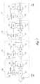
- FIG. 1shows a block diagram of one embodiment of a distributed digital antenna system of the present invention.
- FIG. 2shows a block diagram of another embodiment of a distributed digital antenna system of the present invention.
- FIG. 3shows a block diagram of one embodiment of a remote unit in accordance with the system of FIG. 1 .
- FIG. 4shows a block diagram of one embodiment of a remote unit in accordance with the system of FIG. 2 .
- FIG. 5shows a block diagram of one embodiment of a system having distributed summation and gain control with head end common aggregate attenuation.
- FIG. 6shows a block diagram of one embodiment of a system having distributed summation and gain control with localized common attenuation.
- FIG. 7shows a block diagram of one embodiment of a system having distributed summation and gain control with localized input attenuation.
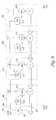
- FIG. 8shows a block diagram of one embodiment of a system having distributed summation and gain control with head end generated feedback control.
- FIG. 9shows a block diagram of one embodiment of a system having distributed summation and gain control with distributed feedback control.
- the embodiments of the present inventionretain the original system dynamic range. By doing so, no additional bits are needed to represent the aggregate signal from the distributed antennas.
- the embodiments of the present inventionrefer to fiber optics as a communications medium between remote units and the host unit.
- the communications medium connecting the remote units to the host unitcan take any form including a laser through an air interface, an RF signal over coaxial cable, or an RF signal through an air interface.
- FIG. 1illustrates a block diagram of one embodiment of a distributed digital antenna system of the present invention.
- the systemhas a base station ( 100 ) that communicates over an RF link using an antenna ( 110 ).
- the base stationcommunicates over the RF link using any appropriate air interface standard.
- the air interface standardcomprises one of Advanced Mobile Phone System (AMPS), code division multiple access (CDMA), time division multiple access (TDMA) Global System for Mobile communications (GSM), or any other appropriate air interface standard.
- AMPSAdvanced Mobile Phone System
- CDMAcode division multiple access
- TDMAtime division multiple access
- GSMGlobal System for Mobile communications
- the RF linkis made up of a forward link over which the base station ( 100 ) transmits to a subscriber unit ( 150 ).
- the subscriber unit ( 150 )transmits back to the base station ( 100 ) over a reverse link.
- the subscriber unit ( 150 )is either a mobile station or a fixed station such as in a wireless local loop system.
- the base station ( 100 )has the transmitters and receivers that enable the subscriber unit ( 150 ) to communicate with the public switched telephone network (PSTN) ( 130 ).
- PSTNpublic switched telephone network
- the base stationlinks the subscriber unit ( 150 ) to other subscriber units that are communicating with other base stations.
- the base station ( 100 )is connected to the PSTN through a mobile switching center that handles the switching of calls with multiple base stations.
- a host unit ( 101 )is connected to the base station ( 100 ) through an RF link ( 115 ).
- this link ( 115 )is a coaxial cable.
- Other embodimentsuse other types of connections such as an air interface or an optical fiber carrying digital RF signals.
- the host unit ( 101 )is responsible for converting the RF signal from the base station ( 100 ) to an optical signal for transmission over an optical medium.
- the host unit ( 101 )also converts a received optical signal to an RF signal for transmission to the base station ( 100 ).
- the host unit ( 101 )performs additional functions.
- One or more remote units ( 105 - 108 )are connected to the host unit ( 101 ) through an optical medium, such as fiber optic lines ( 120 and 125 ), in a daisy-chain arrangement.
- the remote units ( 105 - 108 )are placed in locations that require additional signal coverage due to a lack of coverage by the base station ( 100 ).
- the remote units ( 105 - 108 )communicate with subscriber units in a particular remote unit's coverage area over an RF link provided by the remote unit antennas ( 135 - 138 ).
- remote units 105 - 108For purposes of illustration, four remote units ( 105 - 108 ) are shown. However, alternate embodiments use other quantities of remote units. If only a small geographic area requires coverage, as few as one remote unit ( 105 ) is used. If a highway in a remote area requires additional coverage, more than four remote units are typically used.
- the embodiment of FIG. 1uses a separate fiber optic line for each direction of communication.
- Each fibercarries a different wavelength.
- the fiber optic line ( 120 ) from the host unit ( 101 ) to the remote units ( 105 - 108 )carries a wavelength of ⁇ 1 .
- the fiber optic line ( 125 ) from the remote units ( 105 - 108 ) to the host unit ( 101 )carries a wavelength of ⁇ 2 .
- each fibercarries the same wavelength.
- the fiber optic line ( 120 ) from the host unit ( 101 ) to the remote units ( 105 - 108 )carries the digital optical signal for transmission by the remote units ( 105 - 108 ).
- the fiber optic line ( 125 ) from the remote units ( 105 - 108 )carries a digital optical signal comprising the sum of the received signals from each of the remote units ( 105 - 108 ). The generation of this summation signal from the remote units is discussed subsequently.
- FIG. 2illustrates a block diagram of another embodiment of a distributed digital antenna system of the present invention. This system is similar to the embodiment of FIG. 1 except that the remote units ( 205 - 208 ) are connected to the host unit ( 201 ) over a single optical medium ( 220 ).
- the system of FIG. 2has a base station ( 200 ) that communicates over an RF link using an antenna ( 210 ).
- the base stationcan communicate over the RF link using any air interface standard.
- the air interface standardmay be code division multiple access (CDMA), time division multiple access (TDMA), or Global System for Mobile communications (GSM).
- the RF linkis made up of a forward link over which the base station ( 200 ) transmits to a subscriber unit ( 250 ).
- the subscriber unit ( 250 )transmits back to the base station ( 200 ) over a reverse link.
- the subscriber unit ( 250 )may be a mobile station or a fixed station such as in a wireless local loop system.
- the base station ( 200 )has the transmitters and receivers that enable the subscriber unit ( 250 ) to communicate with the public switched telephone network (PSTN) ( 230 ).
- PSTNpublic switched telephone network
- the base stationmay also link the subscriber unit ( 250 ) to other subscriber units that are communicating with other base stations.
- the base station ( 200 )is connected to the PSTN through a mobile switching center that handles the switching of calls with multiple base stations.
- a host unit ( 201 )is connected to the base station ( 200 ) through an RF link ( 215 ).
- this link ( 215 )is a coaxial cable.
- Other embodimentsuse other types of connections such as an air interface or an optical fiber carrying digital RF signals.
- the host unit ( 201 )is responsible for converting the RF signal from the base station ( 200 ) to a digital optical signal for transmission over an optical medium.
- the host unit ( 201 )also converts a received optical signal to an RF signal for transmission to the base station ( 200 ).
- the host unit ( 201 )performs additional functions.
- One or more remote units ( 205 - 208 )are connected to the host unit ( 201 ) through an optical medium, such as a fiber optic line ( 220 ), that is connected in a daisy-chain arrangement.
- the remote units ( 205 - 208 )are placed in locations that require additional signal coverage due to a lack of coverage by the base station ( 200 ).
- remote units 205 - 208For purposes of illustration, four remote units ( 205 - 208 ) are shown. However, alternate embodiments use other quantities of remote units depending on the application.
- the embodiment of FIG. 2uses a single fiber optic line ( 220 ) for communication both to and from the remote units ( 205 - 208 ). This is accomplished by the single fiber ( 220 ) carrying multiple wavelengths.
- the fiber optic line ( 220 )uses a wavelength of ⁇ 1 for the digital signal from the host unit to the remote units ( 205 - 208 ).
- the fiber optic line ( 220 )also carries a digital summation signal with a wavelength of ⁇ 2 .
- This digital summation signalis the sum of the received signals from the remote units ( 205 - 208 ). The generation of this summation signal from the remote units is discussed subsequently.
- FIG. 3illustrates a block diagram of one embodiment of a remote unit ( 105 ) of FIG. 1 .
- Each of the remote units ( 105 - 108 ) of the embodiment of FIG. 1are substantially identical in functional composition.
- the remote unit ( 105 )transmits and receives RF communication signals over the antenna ( 135 ). Both the receive and transmit circuitry is connected to the antenna ( 135 ) through a diplexer ( 301 ). Alternate embodiments use other quantities of antennas. For example, one embodiment uses three antennas to cover three different sectors of an area.
- An analog signal that is received on the antenna ( 135 )is split off by the diplexer ( 301 ) to an analog-to-digital converter ( 305 ).
- the analog-to-digital converter ( 305 )digitizes the received analog signal by periodically sampling the signal. The sampling generates a digital representation of the received analog signal.
- the digitized received signalis input to a summer ( 315 ) to be added to the digitized signals from the preceding remote units in the daisy-chain.
- the input of the summer ( 315 )therefore, is coupled to an output of a previous remote unit.
- the output of the summer ( 315 )is a summation signal that is coupled to either the input of a subsequent remote unit or to the host unit.
- the host unitthus receives a summation signal that represents the sum of all the signals received by the remote units ( 105 - 108 ) of the system.
- a digital signal from the host unitis coupled to a digital-to-analog converter ( 310 ).
- the digital-to-analog converter ( 310 )takes the digital representation of an analog signal and converts it to the analog signal for transmission by the antenna ( 135 ).
- Optical-to-Electrical converters ( 320 - 323 )are located at the optical ports ( 330 and 335 ) of the remote unit ( 105 ). Each optical port ( 330 and 335 ) has an input and an output that are each coupled to an Optical-to-Electrical converter ( 320 - 323 ).
- the Optical-to-Electrical converters ( 320 - 323 )are responsible for converting the optical signals to electrical signals for processing by the remote unit ( 105 ). Received electrical signals are converted from electrical to an optical representation for transmission over the optical fiber.
- FIG. 4illustrates a block diagram of one embodiment of a remote unit ( 205 ) of FIG. 2 .
- Each of the remote units ( 205 - 208 ) of the embodiment of FIG. 1is substantially identical in functional composition.
- the remote unit ( 205 )transmits and receives RF communication signals over the antenna ( 435 ). Both the receive and transmit circuitry are connected to the antenna ( 435 ) through a diplexer ( 401 ). Alternate embodiments use other quantities of antennas. For example, one embodiment uses three antennas to cover three different sectors of an area.
- An analog signal that is received on the antenna ( 435 )is split off by the diplexer ( 401 ) to an analog-to-digital converter ( 405 ).
- the analog-to-digital converter ( 405 )digitizes the received analog signal by periodically sampling the signal. The sampling generates a digital representation of the received analog signal.
- the digitized received signalis input to a summer ( 415 ) to be added to the digitized signals from the preceding remote units in the daisy-chain.
- the host unitthus receives a summation signal that represents the sum of all the signals received by the remote units ( 205 - 208 ) of the system.
- a digital signal from the host unitis coupled to a digital-to-analog converter ( 410 ).
- the digital-to-analog converter ( 410 )takes the digital representation of an analog signal and converts it to the analog signal for transmission by the antenna ( 435 ).
- Optical-to-Electrical converters ( 420 - 423 )are located at the optical ports ( 440 and 445 ) of the remote unit ( 205 ). Each optical port ( 440 and 445 ) has an input and an output that are each coupled to an Optical-to-Electrical converter ( 420 - 423 ).
- the Optical-to-Electrical converters( 420 - 423 ) are responsible for converting the optical signals to electrical signals for processing by the remote unit ( 205 ). Received electrical signals are converted from electrical to an optical representation for transmission over the optical fiber.
- a wavelength division multiplexer (WDM)( 430 and 431 ) is located at each optical port ( 440 and 445 ).
- the WDMs ( 430 and 431 )perform the optical multiplexing necessary to combine several optical signals having several wavelengths.
- the WDMs ( 430 and 431 )also perform the optical demultiplexing necessary to split the multiple wavelengths of a single fiber to their own signal paths.
- the dynamic range for one antenna portis 14 bits at 84 dB.
- an additional 30 dB and 5 bitsare required.
- the analog-to-digital resolution for each portstill remains at 14 bits but the summation of all the antenna port signals is represented by 19 bits.
- the distributed attenuation of the embodiments of the present inventionuse attenuators at antenna port inputs, outputs, or both.
- the distributed controlmay use a head-end based controller with feedback to each antenna port, local controllers at each antenna port, or distributed control with distributed feedback.
- AGLautomatic gain limiting
- AGCautomatic gain control
- the embodiments of the present inventionemploy different methods of attenuation. These methods include continuous attenuation and stepped attenuation.
- Continuous attenuationis continuous in value.
- the valuespecifies exactly as much attenuation as is needed.
- the attenuationcould be proportional to the excess sampled signal level above a maximum threshold. If the aggregate signal is 2.3 dB above the maximum threshold, the attenuator introduces exactly 2.3 dB of attenuation.
- This method of attenuationis accomplished by multiplying the aggregate value by the appropriate attenuation factor.
- the attenuation factoris between 0, for infinite attenuation, and 1 for no attenuation. Other embodiments may use other number ranges to represent the attenuation factor.
- Stepped attenuationuses a limited set of numbers to provide attenuation in discrete increments.
- the set of numbersrepresents a corresponding set of attenuation factors.
- the numbers 0 through 5represents attenuation factors from 0 to 30 dB in 6 dB increments. Other embodiments may use other numbers to represent other ranges.
- 6 dB of attenuationis applied. Every additional 6 dB above the threshold another 6 dB of attenuation is applied.
- the 6 dB incrementscan be accomplished in a binary number by bit shifting in the direction of a smaller value.
- One shiftequals 6 dB
- two shiftsequals 12 dB
- three shiftsequals 18 dB. This can be continued for as much attenuation as required.
- five shifts of 6 dBaccommodate 30 dB of attenuation.
- the embodiments of the present inventionuse automatic gain limiting based on various methods of sensing levels and applying attenuation. These methods include gain limiting based on the sensing of input signal levels, the sensing of common output signal levels, the sensing of feedback signal levels, or various combinations of these. In addition, these methods include applying attenuation to the input signals, to the common (aggregate) output signals, or both.
- transport path and aggregate signal levelse.g., 14 bits. This is for illustration purposes only. The present invention is not limited to any one transport path size or aggregate signal level.
- FIG. 5illustrates a block diagram of one embodiment of a system having distributed summation and gain control with head end common attenuation.
- a functional equivalent of the above-described remote unit, in this and subsequent embodiments,is illustrated as an antenna ( 509 ) with a summation symbol ( 513 ).
- FIG. 5includes the four remote units ( 501 - 504 ) and the host unit ( 505 ) as described previously.
- Each remote unit ( 501 - 504 )has an antenna ( 506 - 509 ) that receives RF signals that are digitized and summed ( 510 - 513 ) with any previous remote unit signals.
- the summations ( 510 - 513 ) and transport path ( 530 - 532 ) to each remote unitshould have sufficient dynamic range to deliver the aggregate dynamic range.
- the full dynamic rangeis 19 bits for 32 antenna ports. This embodiment assumes that all of the remote units are substantially identical.
- the host unit ( 505 )located at the head end, performs the AGL ( 515 ) and attenuation ( 525 ) functions.
- the AGL function ( 515 )samples ( 520 ) the aggregate signal ( 534 ) from the last remote unit ( 504 ) before the host unit ( 505 ).
- This signalrequires 19 bits for a dynamic range of 114 dB.
- Other embodimentshave other bit quantities to represent other dynamic ranges.
- the AGL function ( 515 )determines that the aggregate signal ( 534 ) is greater than the maximum allowable dynamic range, the AGL function ( 515 ) instructs the attenuation function ( 525 ) to attenuate the common signal.
- the attenuation function ( 525 )may be stepped or continuous.
- the AGL functionis based on sensing the common output signal level and attenuating the common output signal level.
- the attenuation functionattenuates the signal to 14 bits.
- the signal from the host unit ( 505 ) to a base stationwill be within the allowable dynamic range.
- FIG. 6illustrates a block diagram of one embodiment of a system having distributed summation and gain control with localized common attenuation.
- This embodimentuses a standard transport path ( 601 - 604 ) (e.g., 14 bits) by applying localized attenuation to its aggregate signal.
- Each remote unit ( 620 - 623 )attenuates its common output level so that the maximum level is not exceeded.
- the aggregate of all summations ( 615 - 618 ) and attenuations ( 605 - 608 )results in a head end aggregate signal ( 630 ) that does not exceed the maximum level.
- the AGL function ( 610 - 613 ) of each remote unit ( 620 - 623 )samples the common signal level output ( 601 - 604 ) from the respective summation ( 615 - 618 ). If the signal level is greater than the allowable dynamic range, the AGL function ( 610 - 613 ) instructs its respective output attenuation function ( 605 - 608 ) to attenuate that particular common signal output.
- FIG. 7illustrates a block diagram of one embodiment of a system having distributed summation and gain control with localized input attenuation.
- each of the remote units ( 701 - 704 )uses an AGL function ( 725 - 728 ) to control attenuation functions ( 710 - 713 and 720 - 723 ) on the summation ( 730 - 733 ) inputs.
- the input signals that are attenuated in this embodimentinclude both the antenna port and the downstream port.
- the AGL function ( 726 )samples the downstream signal path input ( 750 ) and the antenna port input ( 751 ). If the dynamic range of either input is greater than the allowable maximum, the AGL function ( 726 ) instructs the downstream attenuation function ( 711 ), the antenna attenuation function ( 721 ), or both to attenuate the corresponding input signal.
- FIG. 8illustrates a block diagram of one embodiment of a system having distributed summation and gain control with head end common attenuation. This embodiment uses an AGL function ( 820 ) at the host unit ( 825 ) to provide feedback ( 830 ) to the remote units ( 801 - 804 ).
- AGL function820
- the host unit825
- feedback830
- the remote units801 - 804
- Each remote unit ( 801 - 804 )has an input attenuation function ( 810 - 813 ) at the antenna port to provide.
- An AGL function ( 815 - 818 )samples the antenna port's received signal level. This level along with the feedback information from the head end AGL ( 820 ) is used to determine individual attenuation instructions to the input attenuation functions ( 810 - 813 ).
- the embodiment of FIG. 8additionally uses an AGL function ( 820 ) at the host unit ( 825 ) to sample the final aggregate signal ( 831 ).
- the host unit's AGL function ( 820 )provides a head end feedback attenuation signal ( 830 ) to all of the remote units' AGL functions ( 815 - 818 ) to use in conjunction with the sampled input communication signal levels.
- This feedback signal ( 830 )uses one or more bits in the data being transmitted along the optical medium to the remote units ( 801 - 804 ) from the host unit ( 825 ).
- Another embodimentuses a single bit as a communications channel to provide the feedback information.
- the feedback attenuation signal ( 830 )is a head end continuous attenuation factor.
- this factoris comprised of a value between 0 and 1.
- the localized AGL ( 815 - 818 )uses this factor in addition to the local input signal level to determine what attenuation, if any, to apply locally.
- the continuous attenuationis accomplished by multiplication.
- the feedback attenuation signal ( 830 )is a head end stepped attenuation factor.
- this factoris comprised of an integer value between 0 and 5.
- the localized AGL ( 815 - 818 )uses this factor in addition to the local input signal level to determine what stepped attenuation, if any, to apply locally.
- the stepped attenuationis accomplished by bit shifting.
- the AGL function ( 820 ) at the host unit ( 825 )adjusts its feedback attenuation factor to whatever value is needed (e.g., 0.4 in a continuous feedback system ranging from 0 to 1). This value is dynamic and is lowered until the desired aggregate signal level is achieved.
- the host unit's AGL function ( 820 )samples the final aggregate signal ( 831 ) from the remote unit ( 804 ) nearest the head end. If the level of the final aggregate signal ( 831 ) is too large, the host unit ( 825 ) provides a feedback attenuation factor that starts at one and slews down toward zero. When the final aggregate signal level is within bounds (i.e., less than the maximum dynamic range), the host unit holds this attenuation factor.
- the host unit ( 825 )slowly raises the attenuation factor back toward one. All of the remote units ( 801 - 804 ) apply attenuation only to their own ports. This applied attenuation depends on the respective antenna port's input level as well as the feedback factor ( 830 ).
- the host unit ( 825 )samples the final aggregate signal ( 831 ) from the remote unit ( 804 ) nearest the head end. If the final aggregate signal ( 831 ) is too large, the host unit ( 825 ) provides a feedback number. In one embodiment, this is a number that starts at 0 (no attenuation) and increments towards 5 (maximum attenuation). This embodiment assumes 6 dB per step and accommodates 30 db attenuation. Other embodiments use other increments and other ranges.
- the host unit's AGL function( 820 ) holds this feedback number. If the final aggregate signal level decreases to a predetermined level (e.g., ⁇ 12 dB), the host unit decrements the feedback number back towards 0. The decrementing occurs after a delay due to system end-to-end response.
- FIG. 9illustrates a block diagram of one embodiment of a system having distributed summation, distributed attenuation, and distributed attenuation control.
- each remote unit( 901 - 904 ) re-computes the AGL feedback factor for downstream units.
- every unit ( 901 - 904 )is functionally identical with the same AGL function ( 910 - 913 ).
- the AGL functionhas both an input feedback factor (from the direction of the head end), a signal from the sampled antenna input, and an input from the common output. At the head end unit ( 904 ), the input feedback is unconnected.
- Each AGL function ( 910 - 913 )has two outputs. One output is used to control the attenuation ( 905 - 908 ) of the antenna signal input. The other output is used to provide an output feedback factor in the direction of the tail end. At the tail end ( 901 ) the output feedback is unconnected.
- the AGL function( 910 - 913 ) determines a factor related to the common input signal.
- the output feedback factoris based on both this common factor and the input feedback factor. In one embodiment, the most severe factor is used.
- the AGL function ( 910 - 913 )also determines amount of input attenuation ( 905 - 908 ) to the antenna signal. This attenuation is based on the input feedback factor, the input antenna signal level, and the common input signal level.
- the host unitgenerates the highest attenuation factor because its aggregate signal is the largest. Because of the feedback, all units normally use this factor to apply attenuation. Since all of the remote units also sample their own antenna port, in one embodiment they will apply no attenuation or little attenuation to sufficiently small signals and apply large attenuation to large signals. That is, the gain is inversely proportional to the large signal level.
- the aggregate sampling at each remote unitprevents any unit's aggregate signal from overflowing. Furthermore, all units from the tail end to the point of the break will perform fair sharing of the aggregate signals amongst themselves. Similarly, all units from the break to the head end will perform fair sharing of the aggregate signals amongst themselves. However, the tail end group is favored over the head end group.
Landscapes
- Engineering & Computer Science (AREA)
- Computer Networks & Wireless Communication (AREA)
- Signal Processing (AREA)
- Physics & Mathematics (AREA)
- Electromagnetism (AREA)
- Mobile Radio Communication Systems (AREA)
- Variable-Direction Aerials And Aerial Arrays (AREA)
- Circuits Of Receivers In General (AREA)
Abstract
Description
Claims (17)
Priority Applications (1)
| Application Number | Priority Date | Filing Date | Title |
|---|---|---|---|
| US12/467,924US7917177B2 (en) | 2002-12-03 | 2009-05-18 | Communication system and method with gain control for signals from distributed antennas |
Applications Claiming Priority (3)
| Application Number | Priority Date | Filing Date | Title |
|---|---|---|---|
| US10/308,854US7171244B2 (en) | 2002-12-03 | 2002-12-03 | Communication system and method with gain control for signals from distributed antennas |
| US11/624,541US7546138B2 (en) | 2002-12-03 | 2007-01-18 | Communication system and method with gain control for signals from distributed antennas |
| US12/467,924US7917177B2 (en) | 2002-12-03 | 2009-05-18 | Communication system and method with gain control for signals from distributed antennas |
Related Parent Applications (1)
| Application Number | Title | Priority Date | Filing Date |
|---|---|---|---|
| US11/624,541ContinuationUS7546138B2 (en) | 2002-12-03 | 2007-01-18 | Communication system and method with gain control for signals from distributed antennas |
Publications (2)
| Publication Number | Publication Date |
|---|---|
| US20090238573A1 US20090238573A1 (en) | 2009-09-24 |
| US7917177B2true US7917177B2 (en) | 2011-03-29 |
Family
ID=32467817
Family Applications (3)
| Application Number | Title | Priority Date | Filing Date |
|---|---|---|---|
| US10/308,854Expired - LifetimeUS7171244B2 (en) | 2002-12-03 | 2002-12-03 | Communication system and method with gain control for signals from distributed antennas |
| US11/624,541Expired - LifetimeUS7546138B2 (en) | 2002-12-03 | 2007-01-18 | Communication system and method with gain control for signals from distributed antennas |
| US12/467,924Expired - LifetimeUS7917177B2 (en) | 2002-12-03 | 2009-05-18 | Communication system and method with gain control for signals from distributed antennas |
Family Applications Before (2)
| Application Number | Title | Priority Date | Filing Date |
|---|---|---|---|
| US10/308,854Expired - LifetimeUS7171244B2 (en) | 2002-12-03 | 2002-12-03 | Communication system and method with gain control for signals from distributed antennas |
| US11/624,541Expired - LifetimeUS7546138B2 (en) | 2002-12-03 | 2007-01-18 | Communication system and method with gain control for signals from distributed antennas |
Country Status (7)
| Country | Link |
|---|---|
| US (3) | US7171244B2 (en) |
| EP (1) | EP1570687B1 (en) |
| KR (1) | KR101030580B1 (en) |
| CN (1) | CN100417241C (en) |
| AU (1) | AU2003298828A1 (en) |
| TW (1) | TW200417079A (en) |
| WO (1) | WO2004051873A2 (en) |
Cited By (81)
| Publication number | Priority date | Publication date | Assignee | Title |
|---|---|---|---|---|
| US20120064838A1 (en)* | 2009-05-20 | 2012-03-15 | Telefonaktiebolaget L M Ericsson (Publ) | Automatic Detection of Erroneous Connections Between Antenna Ports and Radio Frequency Paths |
| US8532492B2 (en) | 2009-02-03 | 2013-09-10 | Corning Cable Systems Llc | Optical fiber-based distributed antenna systems, components, and related methods for calibration thereof |
| US8639121B2 (en) | 2009-11-13 | 2014-01-28 | Corning Cable Systems Llc | Radio-over-fiber (RoF) system for protocol-independent wired and/or wireless communication |
| US8644844B2 (en) | 2007-12-20 | 2014-02-04 | Corning Mobileaccess Ltd. | Extending outdoor location based services and applications into enclosed areas |
| US8718478B2 (en) | 2007-10-12 | 2014-05-06 | Corning Cable Systems Llc | Hybrid wireless/wired RoF transponder and hybrid RoF communication system using same |
| US8831428B2 (en) | 2010-02-15 | 2014-09-09 | Corning Optical Communications LLC | Dynamic cell bonding (DCB) for radio-over-fiber (RoF)-based networks and communication systems and related methods |
| US8867919B2 (en) | 2007-07-24 | 2014-10-21 | Corning Cable Systems Llc | Multi-port accumulator for radio-over-fiber (RoF) wireless picocellular systems |
| US8873585B2 (en) | 2006-12-19 | 2014-10-28 | Corning Optical Communications Wireless Ltd | Distributed antenna system for MIMO technologies |
| US8897215B2 (en) | 2009-02-08 | 2014-11-25 | Corning Optical Communications Wireless Ltd | Communication system using cables carrying ethernet signals |
| USRE45321E1 (en)* | 1992-09-17 | 2015-01-06 | Adc Telecommunications, Inc. | Cellular communications system with sectorization |
| US8958789B2 (en) | 2002-12-03 | 2015-02-17 | Adc Telecommunications, Inc. | Distributed digital antenna system |
| US8983301B2 (en) | 2010-03-31 | 2015-03-17 | Corning Optical Communications LLC | Localization services in optical fiber-based distributed communications components and systems, and related methods |
| US9158864B2 (en) | 2012-12-21 | 2015-10-13 | Corning Optical Communications Wireless Ltd | Systems, methods, and devices for documenting a location of installed equipment |
| US9178635B2 (en) | 2014-01-03 | 2015-11-03 | Corning Optical Communications Wireless Ltd | Separation of communication signal sub-bands in distributed antenna systems (DASs) to reduce interference |
| US9179321B2 (en) | 2012-08-09 | 2015-11-03 | Axell Wireless Ltd. | Digital capacity centric distributed antenna system |
| US9185674B2 (en) | 2010-08-09 | 2015-11-10 | Corning Cable Systems Llc | Apparatuses, systems, and methods for determining location of a mobile device(s) in a distributed antenna system(s) |
| US9184960B1 (en) | 2014-09-25 | 2015-11-10 | Corning Optical Communications Wireless Ltd | Frequency shifting a communications signal(s) in a multi-frequency distributed antenna system (DAS) to avoid or reduce frequency interference |
| US9184843B2 (en) | 2011-04-29 | 2015-11-10 | Corning Optical Communications LLC | Determining propagation delay of communications in distributed antenna systems, and related components, systems, and methods |
| US9240835B2 (en) | 2011-04-29 | 2016-01-19 | Corning Optical Communications LLC | Systems, methods, and devices for increasing radio frequency (RF) power in distributed antenna systems |
| US9247543B2 (en) | 2013-07-23 | 2016-01-26 | Corning Optical Communications Wireless Ltd | Monitoring non-supported wireless spectrum within coverage areas of distributed antenna systems (DASs) |
| US9258052B2 (en) | 2012-03-30 | 2016-02-09 | Corning Optical Communications LLC | Reducing location-dependent interference in distributed antenna systems operating in multiple-input, multiple-output (MIMO) configuration, and related components, systems, and methods |
| US9338823B2 (en) | 2012-03-23 | 2016-05-10 | Corning Optical Communications Wireless Ltd | Radio-frequency integrated circuit (RFIC) chip(s) for providing distributed antenna system functionalities, and related components, systems, and methods |
| US9357551B2 (en) | 2014-05-30 | 2016-05-31 | Corning Optical Communications Wireless Ltd | Systems and methods for simultaneous sampling of serial digital data streams from multiple analog-to-digital converters (ADCS), including in distributed antenna systems |
| US9385810B2 (en) | 2013-09-30 | 2016-07-05 | Corning Optical Communications Wireless Ltd | Connection mapping in distributed communication systems |
| US9420542B2 (en) | 2014-09-25 | 2016-08-16 | Corning Optical Communications Wireless Ltd | System-wide uplink band gain control in a distributed antenna system (DAS), based on per band gain control of remote uplink paths in remote units |
| US9419712B2 (en) | 2010-10-13 | 2016-08-16 | Ccs Technology, Inc. | Power management for remote antenna units in distributed antenna systems |
| US9455784B2 (en) | 2012-10-31 | 2016-09-27 | Corning Optical Communications Wireless Ltd | Deployable wireless infrastructures and methods of deploying wireless infrastructures |
| US9497706B2 (en) | 2013-02-20 | 2016-11-15 | Corning Optical Communications Wireless Ltd | Power management in distributed antenna systems (DASs), and related components, systems, and methods |
| US9509133B2 (en) | 2014-06-27 | 2016-11-29 | Corning Optical Communications Wireless Ltd | Protection of distributed antenna systems |
| US9525472B2 (en) | 2014-07-30 | 2016-12-20 | Corning Incorporated | Reducing location-dependent destructive interference in distributed antenna systems (DASS) operating in multiple-input, multiple-output (MIMO) configuration, and related components, systems, and methods |
| US9531452B2 (en) | 2012-11-29 | 2016-12-27 | Corning Optical Communications LLC | Hybrid intra-cell / inter-cell remote unit antenna bonding in multiple-input, multiple-output (MIMO) distributed antenna systems (DASs) |
| US9549301B2 (en) | 2007-12-17 | 2017-01-17 | Corning Optical Communications Wireless Ltd | Method and system for real time control of an active antenna over a distributed antenna system |
| US9577922B2 (en) | 2014-02-18 | 2017-02-21 | Commscope Technologies Llc | Selectively combining uplink signals in distributed antenna systems |
| US9590733B2 (en) | 2009-07-24 | 2017-03-07 | Corning Optical Communications LLC | Location tracking using fiber optic array cables and related systems and methods |
| US9602210B2 (en) | 2014-09-24 | 2017-03-21 | Corning Optical Communications Wireless Ltd | Flexible head-end chassis supporting automatic identification and interconnection of radio interface modules and optical interface modules in an optical fiber-based distributed antenna system (DAS) |
| US9621293B2 (en) | 2012-08-07 | 2017-04-11 | Corning Optical Communications Wireless Ltd | Distribution of time-division multiplexed (TDM) management services in a distributed antenna system, and related components, systems, and methods |
| US9647758B2 (en) | 2012-11-30 | 2017-05-09 | Corning Optical Communications Wireless Ltd | Cabling connectivity monitoring and verification |
| US9648580B1 (en) | 2016-03-23 | 2017-05-09 | Corning Optical Communications Wireless Ltd | Identifying remote units in a wireless distribution system (WDS) based on assigned unique temporal delay patterns |
| US9653861B2 (en) | 2014-09-17 | 2017-05-16 | Corning Optical Communications Wireless Ltd | Interconnection of hardware components |
| US9661781B2 (en) | 2013-07-31 | 2017-05-23 | Corning Optical Communications Wireless Ltd | Remote units for distributed communication systems and related installation methods and apparatuses |
| US9673904B2 (en) | 2009-02-03 | 2017-06-06 | Corning Optical Communications LLC | Optical fiber-based distributed antenna systems, components, and related methods for calibration thereof |
| US9681313B2 (en) | 2015-04-15 | 2017-06-13 | Corning Optical Communications Wireless Ltd | Optimizing remote antenna unit performance using an alternative data channel |
| US9685782B2 (en) | 2010-11-24 | 2017-06-20 | Corning Optical Communications LLC | Power distribution module(s) capable of hot connection and/or disconnection for distributed antenna systems, and related power units, components, and methods |
| US9699723B2 (en) | 2010-10-13 | 2017-07-04 | Ccs Technology, Inc. | Local power management for remote antenna units in distributed antenna systems |
| US9715157B2 (en) | 2013-06-12 | 2017-07-25 | Corning Optical Communications Wireless Ltd | Voltage controlled optical directional coupler |
| US9729251B2 (en) | 2012-07-31 | 2017-08-08 | Corning Optical Communications LLC | Cooling system control in distributed antenna systems |
| US9729267B2 (en) | 2014-12-11 | 2017-08-08 | Corning Optical Communications Wireless Ltd | Multiplexing two separate optical links with the same wavelength using asymmetric combining and splitting |
| US9730228B2 (en) | 2014-08-29 | 2017-08-08 | Corning Optical Communications Wireless Ltd | Individualized gain control of remote uplink band paths in a remote unit in a distributed antenna system (DAS), based on combined uplink power level in the remote unit |
| US9750082B2 (en) | 2013-10-07 | 2017-08-29 | Commscope Technologies Llc | Systems and methods for noise floor optimization in distributed antenna system with direct digital interface to base station |
| US9775123B2 (en) | 2014-03-28 | 2017-09-26 | Corning Optical Communications Wireless Ltd. | Individualized gain control of uplink paths in remote units in a distributed antenna system (DAS) based on individual remote unit contribution to combined uplink power |
| US9781553B2 (en) | 2012-04-24 | 2017-10-03 | Corning Optical Communications LLC | Location based services in a distributed communication system, and related components and methods |
| US9785175B2 (en) | 2015-03-27 | 2017-10-10 | Corning Optical Communications Wireless, Ltd. | Combining power from electrically isolated power paths for powering remote units in a distributed antenna system(s) (DASs) |
| US9807700B2 (en) | 2015-02-19 | 2017-10-31 | Corning Optical Communications Wireless Ltd | Offsetting unwanted downlink interference signals in an uplink path in a distributed antenna system (DAS) |
| US9813229B2 (en) | 2007-10-22 | 2017-11-07 | Corning Optical Communications Wireless Ltd | Communication system using low bandwidth wires |
| US9948349B2 (en) | 2015-07-17 | 2018-04-17 | Corning Optical Communications Wireless Ltd | IOT automation and data collection system |
| US9974074B2 (en) | 2013-06-12 | 2018-05-15 | Corning Optical Communications Wireless Ltd | Time-division duplexing (TDD) in distributed communications systems, including distributed antenna systems (DASs) |
| US10128951B2 (en) | 2009-02-03 | 2018-11-13 | Corning Optical Communications LLC | Optical fiber-based distributed antenna systems, components, and related methods for monitoring and configuring thereof |
| US10136200B2 (en) | 2012-04-25 | 2018-11-20 | Corning Optical Communications LLC | Distributed antenna system architectures |
| US10236924B2 (en) | 2016-03-31 | 2019-03-19 | Corning Optical Communications Wireless Ltd | Reducing out-of-channel noise in a wireless distribution system (WDS) |
| US10257056B2 (en) | 2012-11-28 | 2019-04-09 | Corning Optical Communications LLC | Power management for distributed communication systems, and related components, systems, and methods |
| US10291322B2 (en) | 2014-08-25 | 2019-05-14 | Corning Optical Communications LLC | Supporting an add-on remote unit (RU) in an optical fiber-based distributed antenna system (DAS) over an existing optical fiber communications medium using radio frequency (RF) multiplexing |
| US10396917B2 (en) | 2014-09-23 | 2019-08-27 | Axell Wireless Ltd. | Automatic mapping and handling PIM and other uplink interferences in digital distributed antenna systems |
| US10455497B2 (en) | 2013-11-26 | 2019-10-22 | Corning Optical Communications LLC | Selective activation of communications services on power-up of a remote unit(s) in a wireless communication system (WCS) based on power consumption |
| US10499269B2 (en) | 2015-11-12 | 2019-12-03 | Commscope Technologies Llc | Systems and methods for assigning controlled nodes to channel interfaces of a controller |
| US10498434B2 (en) | 2000-07-19 | 2019-12-03 | CommScope Technolgies LLC | Point-to-multipoint digital radio frequency transport |
| US10560214B2 (en) | 2015-09-28 | 2020-02-11 | Corning Optical Communications LLC | Downlink and uplink communication path switching in a time-division duplex (TDD) distributed antenna system (DAS) |
| US10992484B2 (en) | 2013-08-28 | 2021-04-27 | Corning Optical Communications LLC | Power management for distributed communication systems, and related components, systems, and methods |
| US11064501B2 (en) | 2014-12-23 | 2021-07-13 | Axell Wireless Ltd. | Harmonizing noise aggregation and noise management in distributed antenna system |
| US11150409B2 (en) | 2018-12-27 | 2021-10-19 | GenXComm, Inc. | Saw assisted facet etch dicing |
| US11215755B2 (en) | 2019-09-19 | 2022-01-04 | GenXComm, Inc. | Low loss, polarization-independent, large bandwidth mode converter for edge coupling |
| US11296504B2 (en) | 2010-11-24 | 2022-04-05 | Corning Optical Communications LLC | Power distribution module(s) capable of hot connection and/or disconnection for wireless communication systems, and related power units, components, and methods |
| US11309965B2 (en) | 2019-07-15 | 2022-04-19 | GenXComm, Inc. | Efficiently combining multiple taps of an optical filter |
| US11330464B2 (en) | 2016-07-16 | 2022-05-10 | GenXComm, Inc. | Interference cancellation methods and apparatus |
| US11469821B2 (en) | 2015-12-13 | 2022-10-11 | GenXComm, Inc. | Interference cancellation methods and apparatus |
| US11539394B2 (en) | 2019-10-29 | 2022-12-27 | GenXComm, Inc. | Self-interference mitigation in in-band full-duplex communication systems |
| US11796737B2 (en) | 2020-08-10 | 2023-10-24 | GenXComm, Inc. | Co-manufacturing of silicon-on-insulator waveguides and silicon nitride waveguides for hybrid photonic integrated circuits |
| US11838056B2 (en) | 2021-10-25 | 2023-12-05 | GenXComm, Inc. | Hybrid photonic integrated circuits for ultra-low phase noise signal generators |
| US20240154702A1 (en)* | 2021-01-29 | 2024-05-09 | Comba Network Systems Company Limited | Indoor distribution system and signal transmission method |
| US12001065B1 (en) | 2020-11-12 | 2024-06-04 | ORCA Computing Limited | Photonics package with tunable liquid crystal lens |
| US12057873B2 (en) | 2021-02-18 | 2024-08-06 | GenXComm, Inc. | Maximizing efficiency of communication systems with self-interference cancellation subsystems |
| US12317113B2 (en) | 2021-04-29 | 2025-05-27 | Gxc, Llc | Self-interference cancellation subsystems for mesh network nodes |
Families Citing this family (58)
| Publication number | Priority date | Publication date | Assignee | Title |
|---|---|---|---|---|
| DE20306733U1 (en) | 2002-05-01 | 2003-10-16 | InterDigital Technology Corporation, Wilmington, Del. | Radio Network Control Unit (RNC) capable of supporting point-to-multipoint services using shared channels |
| TWI390999B (en) | 2002-05-01 | 2013-03-21 | Interdigital Tech Corp | Point-to-multipoint service using high-speed shared channels in wireless communication systems |
| JP4124710B2 (en)* | 2002-10-17 | 2008-07-23 | 松下電器産業株式会社 | Wireless communication system |
| US7103377B2 (en)* | 2002-12-03 | 2006-09-05 | Adc Telecommunications, Inc. | Small signal threshold and proportional gain distributed digital communications |
| US7469105B2 (en)* | 2004-04-09 | 2008-12-23 | Nextg Networks, Inc. | Optical fiber communications method and system without a remote electrical power supply |
| KR100617839B1 (en)* | 2004-11-16 | 2006-08-28 | 삼성전자주식회사 | Optical network for two-way wireless communication |
| US20070008939A1 (en)* | 2005-06-10 | 2007-01-11 | Adc Telecommunications, Inc. | Providing wireless coverage into substantially closed environments |
| US7599711B2 (en)* | 2006-04-12 | 2009-10-06 | Adc Telecommunications, Inc. | Systems and methods for analog transport of RF voice/data communications |
| CN101141778A (en)* | 2007-09-25 | 2008-03-12 | 中兴通讯股份有限公司 | Method and system for implementing subarea overlapping using mirror-image radio frequency unit |
| US8310963B2 (en)* | 2008-06-24 | 2012-11-13 | Adc Telecommunications, Inc. | System and method for synchronized time-division duplex signal switching |
| WO2010072020A1 (en) | 2008-12-22 | 2010-07-01 | Huawei Technologies Co., Ltd. | Method for signalling in a wireless communication system |
| CN102165712B (en)* | 2008-12-22 | 2015-02-04 | 华为技术有限公司 | Method for signaling in a wireless communication system |
| US8346278B2 (en) | 2009-01-13 | 2013-01-01 | Adc Telecommunications, Inc. | Systems and methods for mobile phone location with digital distributed antenna systems |
| US8213401B2 (en) | 2009-01-13 | 2012-07-03 | Adc Telecommunications, Inc. | Systems and methods for IP communication over a distributed antenna system transport |
| USRE47466E1 (en) | 2009-01-13 | 2019-06-25 | Commscope Technologies Llc | Systems and methods for IP communication over a distributed antenna system transport |
| US8346091B2 (en)* | 2009-04-29 | 2013-01-01 | Andrew Llc | Distributed antenna system for wireless network systems |
| US9001811B2 (en) | 2009-05-19 | 2015-04-07 | Adc Telecommunications, Inc. | Method of inserting CDMA beacon pilots in output of distributed remote antenna nodes |
| US8428510B2 (en)* | 2010-03-25 | 2013-04-23 | Adc Telecommunications, Inc. | Automatic gain control configuration for a wideband distributed antenna system |
| WO2011129547A2 (en)* | 2010-04-12 | 2011-10-20 | 엘지전자 주식회사 | Method and apparatus for transmitting feedback information of a terminal in a multi-node system |
| US8509850B2 (en) | 2010-06-14 | 2013-08-13 | Adc Telecommunications, Inc. | Systems and methods for distributed antenna system reverse path summation using signal-to-noise ratio optimization |
| US8472579B2 (en) | 2010-07-28 | 2013-06-25 | Adc Telecommunications, Inc. | Distributed digital reference clock |
| WO2012024247A1 (en)* | 2010-08-16 | 2012-02-23 | Corning Cable Systems Llc | Remote antenna clusters and related systems, components, and methods supporting digital data signal propagation between remote antenna units |
| US8532242B2 (en) | 2010-10-27 | 2013-09-10 | Adc Telecommunications, Inc. | Distributed antenna system with combination of both all digital transport and hybrid digital/analog transport |
| US8462683B2 (en) | 2011-01-12 | 2013-06-11 | Adc Telecommunications, Inc. | Distinct transport path for MIMO transmissions in distributed antenna systems |
| EP2678972B1 (en) | 2011-02-21 | 2018-09-05 | Corning Optical Communications LLC | Providing digital data services as electrical signals and radio-frequency (rf) communications over optical fiber in distributed communications systems, and related components and methods |
| EP2715947B1 (en) | 2011-06-01 | 2018-08-15 | CommScope Technologies LLC | Broadband distributed antenna system with non-duplexer isolator sub-system |
| EP3843285A1 (en) | 2011-06-13 | 2021-06-30 | CommScope Technologies LLC | Distributed antenna system architectures |
| US8743718B2 (en)* | 2011-06-21 | 2014-06-03 | Adc Telecommunications, Inc. | End-to-end delay management for distributed communications networks |
| US8787223B2 (en) | 2011-09-16 | 2014-07-22 | Rogers Communications Inc. | Coaxial cable distribution of CATV and wireless signals |
| US8693342B2 (en) | 2011-10-28 | 2014-04-08 | Adc Telecommunications, Inc. | Distributed antenna system using time division duplexing scheme |
| US11564110B2 (en)* | 2011-11-07 | 2023-01-24 | Dali Wireless, Inc. | Soft hand-off and routing data in a virtualized distributed antenna system |
| TWI514791B (en) | 2012-09-11 | 2015-12-21 | Ind Tech Res Inst | Radio frequency signal transceiving device and method thereof, self-monitoring optical transmission device and method thereof |
| AU2013338583B2 (en) | 2012-10-31 | 2017-08-31 | Commscope Technologies Llc | Digital baseband transport in telecommunications distribution systems |
| US9191993B2 (en) | 2012-11-20 | 2015-11-17 | Adc Telecommunications, Inc. | Distributed antenna system with uplink bandwidth for signal analysis |
| CA2901666A1 (en) | 2013-02-22 | 2014-08-28 | Adc Telecommunications, Inc. | Universal remote radio head |
| CA2914104C (en) | 2013-02-22 | 2022-12-13 | Adc Telecommunications, Inc. | Master reference for base station network interface sourced from distributed antenna system |
| CN103475400B (en)* | 2013-09-12 | 2016-06-01 | 清华大学 | Improve the sampling data transmission method of receiving end antenna dynamicrange |
| US9450689B2 (en) | 2013-10-07 | 2016-09-20 | Commscope Technologies Llc | Systems and methods for delay management in distributed antenna system with direct digital interface to base station |
| US9787457B2 (en) | 2013-10-07 | 2017-10-10 | Commscope Technologies Llc | Systems and methods for integrating asynchronous signals in distributed antenna system with direct digital interface to base station |
| KR102189745B1 (en)* | 2013-12-06 | 2020-12-14 | 주식회사 쏠리드 | A remote device of optical repeater system |
| US9847828B2 (en)* | 2013-12-18 | 2017-12-19 | X Development Llc | Adjusting beam width of air-to-ground communications based on distance to neighbor balloon(s) in order to maintain contiguous service |
| US20170250927A1 (en) | 2013-12-23 | 2017-08-31 | Dali Systems Co. Ltd. | Virtual radio access network using software-defined network of remotes and digital multiplexing switches |
| US9768855B2 (en) | 2014-01-27 | 2017-09-19 | Commscope Technologies Llc | Multi-stage isolation sub-system for a remote antenna unit |
| US9705609B2 (en) | 2014-04-15 | 2017-07-11 | Commscope Technologies Llc | Wideband remote unit for distributed antenna system |
| AU2015266704A1 (en)* | 2014-05-30 | 2016-11-17 | Commscope Technologies Llc | Integrated analog and digital distributed antenna system (DAS) utilizing an all fiber optic network |
| AU2015274511B2 (en) | 2014-06-11 | 2019-08-15 | Outdoor Wireless Networks LLC | Bitrate efficient transport through distributed antenna systems |
| US10659163B2 (en) | 2014-09-25 | 2020-05-19 | Corning Optical Communications LLC | Supporting analog remote antenna units (RAUs) in digital distributed antenna systems (DASs) using analog RAU digital adaptors |
| WO2016071902A1 (en) | 2014-11-03 | 2016-05-12 | Corning Optical Communications Wireless Ltd. | Multi-band monopole planar antennas configured to facilitate improved radio frequency (rf) isolation in multiple-input multiple-output (mimo) antenna arrangement |
| WO2016075696A1 (en) | 2014-11-13 | 2016-05-19 | Corning Optical Communications Wireless Ltd. | Analog distributed antenna systems (dass) supporting distribution of digital communications signals interfaced from a digital signal source and analog radio frequency (rf) communications signals |
| WO2016098111A1 (en) | 2014-12-18 | 2016-06-23 | Corning Optical Communications Wireless Ltd. | Digital- analog interface modules (da!ms) for flexibly.distributing digital and/or analog communications signals in wide-area analog distributed antenna systems (dass) |
| WO2016098109A1 (en) | 2014-12-18 | 2016-06-23 | Corning Optical Communications Wireless Ltd. | Digital interface modules (dims) for flexibly distributing digital and/or analog communications signals in wide-area analog distributed antenna systems (dass) |
| TW201626746A (en)* | 2015-01-13 | 2016-07-16 | Transystem Inc | Optical fiber communication device and optical fiber communication system |
| US10334572B2 (en) | 2015-02-05 | 2019-06-25 | Commscope Technologies Llc | Systems and methods for emulating uplink diversity signals |
| US9603155B2 (en)* | 2015-07-31 | 2017-03-21 | Corning Optical Communications Wireless Ltd | Reducing leaked downlink interference signals in a remote unit uplink path(s) in a distributed antenna system (DAS) |
| US9894612B1 (en) | 2016-11-03 | 2018-02-13 | Corning Optical Communications Wireless Ltd | Reducing power consumption in a remote unit of a wireless distribution system (WDS) for intermodulation product suppression |
| US10594401B2 (en)* | 2018-07-20 | 2020-03-17 | Frtek Co., Ltd. | Distributed antenna system for transmitting service signal and management control signal in 5G mobile communication system, and remote unit thereof |
| GB2586672B (en)* | 2019-02-23 | 2022-10-12 | Zinwave Ltd | Multi-range communication system |
| CN115296733B (en)* | 2022-07-18 | 2024-02-06 | 三维通信股份有限公司 | Uplink combined signal overflow prevention method, device, DAS system and storage medium |
Citations (44)
| Publication number | Priority date | Publication date | Assignee | Title |
|---|---|---|---|---|
| FR2345865A1 (en) | 1976-03-22 | 1977-10-21 | Sina Spa | PROCESS AND APPARATUS FOR RADIOCOMMUNICATIONS AND / OR RADIO SIGNALS IN CLOSED AREAS |
| US4144411A (en) | 1976-09-22 | 1979-03-13 | Bell Telephone Laboratories, Incorporated | Cellular radiotelephone system structured for flexible use of different cell sizes |
| US4183054A (en) | 1977-09-30 | 1980-01-08 | Harris Corporation | Digital, frequency-translated, plural-channel, vestigial sideband television communication system |
| US4451699A (en)* | 1979-12-31 | 1984-05-29 | Broadcom, Inc. | Communications system and network |
| US4475010A (en)* | 1983-05-05 | 1984-10-02 | At&T Bell Laboratories | High density cellular mobile radio communications |
| US4485486A (en)* | 1982-08-03 | 1984-11-27 | Motorola, Inc. | Method and apparatus for assigning duplex radio channels and scanning duplex radio channels assigned to mobile and portable radio telephones in a cellular radiotelephone communications system |
| US4556760A (en)* | 1984-06-11 | 1985-12-03 | Itt Corporation | Hand-off filter for cellular mobile radio |
| US4611323A (en)* | 1983-05-24 | 1986-09-09 | Ant Nachrichtentechnik Gmbh | Method for transmitting digitally coded analog signals |
| US4628501A (en) | 1983-12-29 | 1986-12-09 | The United States Of America As Represented By The Secretary Of The Army | Optical communications systems |
| US4654843A (en) | 1982-09-17 | 1987-03-31 | U.S. Philips Corporation | Signal distribution system |
| US4691292A (en) | 1983-04-13 | 1987-09-01 | Rca Corporation | System for digital multiband filtering |
| US4849963A (en) | 1985-10-15 | 1989-07-18 | Minori Kawano | Cellular radio telephone enhancement circuit |
| EP0346925A2 (en) | 1988-06-17 | 1989-12-20 | Small Power Communication Systems Research Laboratories Co., Ltd. | Private branch radio communication system using optical fibers |
| US4916460A (en)* | 1988-01-29 | 1990-04-10 | Decibel Products, Incorporated | Distributed antenna system |
| EP0368673A1 (en) | 1988-11-11 | 1990-05-16 | BRITISH TELECOMMUNICATIONS public limited company | Communications system |
| US4999831A (en) | 1989-10-19 | 1991-03-12 | United Telecommunications, Inc. | Synchronous quantized subcarrier multiplexer for digital transport of video, voice and data |
| WO1991015927A1 (en) | 1990-04-10 | 1991-10-17 | British Telecommunications Public Limited Company | Signal distribution |
| US5067173A (en)* | 1990-12-20 | 1991-11-19 | At&T Bell Laboratories | Microcellular communications system using space diversity reception |
| EP0468688A2 (en) | 1990-07-25 | 1992-01-29 | AT&T Corp. | Method and apparatus for providing wireless communications between remote locations |
| US5278690A (en)* | 1991-05-16 | 1994-01-11 | Vella Coleiro George P | Apparatus and method for synchronizing a plurality of remote transmission and receiving stations and providing automatic gain control of the synchronizing signal |
| US5321849A (en)* | 1991-05-22 | 1994-06-14 | Southwestern Bell Technology Resources, Inc. | System for controlling signal level at both ends of a transmission link based on a detected valve |
| GB2300549A (en) | 1995-05-02 | 1996-11-06 | Northern Telecom Ltd | Cellular comms using catv |
| US5621786A (en)* | 1992-09-17 | 1997-04-15 | Adc Telecomminications, Inc. | Cellular communications system having passive handoff |
| US5765099A (en) | 1996-04-19 | 1998-06-09 | Georges; John B. | Distribution of radio-frequency signals through low bandwidth infrastructures |
| US5774789A (en) | 1995-12-14 | 1998-06-30 | Allen Telecom Inc. | RF communication signal distribution system and method |
| US5802173A (en) | 1991-01-15 | 1998-09-01 | Rogers Cable Systems Limited | Radiotelephony system |
| US5809395A (en)* | 1991-01-15 | 1998-09-15 | Rogers Cable Systems Limited | Remote antenna driver for a radio telephony system |
| US5878325A (en)* | 1996-07-12 | 1999-03-02 | At&T Corp | Hybrid fiber-coax system having at least one digital fiber node |
| US5969837A (en) | 1996-12-15 | 1999-10-19 | Foxcom Wireless Ltd. | Communications system |
| US6112086A (en)* | 1997-02-25 | 2000-08-29 | Adc Telecommunications, Inc. | Scanning RSSI receiver system using inverse fast fourier transforms for a cellular communications system with centralized base stations and distributed antenna units |
| US6122529A (en)* | 1998-03-17 | 2000-09-19 | Transcept, Inc. | Simulcast with hierarchical cell structure overlay |
| US6150993A (en) | 1999-03-25 | 2000-11-21 | Zenith Electronics Corporation | Adaptive indoor antenna system |
| US6223021B1 (en)* | 1997-12-24 | 2001-04-24 | Transcept, Inc. | Signal filtering in a transceiver for a wireless telephone system |
| US6259910B1 (en)* | 1998-02-13 | 2001-07-10 | Lucent Technologies, Inc. | Wireless telecommunications system architecture supporting block radio technology |
| US6298246B1 (en) | 1997-11-20 | 2001-10-02 | Airspan Networks, Inc. | Subscriber terminal and method for passing control signals between a first and second signal processing units |
| US6336042B1 (en)* | 1998-06-05 | 2002-01-01 | Transcept, Inc. | Reverse link antenna diversity in a wireless telephony system |
| US6349200B1 (en)* | 1997-12-24 | 2002-02-19 | Transcept, Inc. | Monitoring and command system for transceivers used to inter-connect wireless telephones to a broadband network |
| US6374124B1 (en)* | 1997-12-24 | 2002-04-16 | Transcept, Inc. | Dynamic reallocation of transceivers used to interconnect wireless telephones to a broadband network |
| US6480702B1 (en)* | 1996-08-01 | 2002-11-12 | Transcept, Inc. | Apparatus and method for distributing wireless communications signals to remote cellular antennas |
| US20030143947A1 (en) | 2000-12-28 | 2003-07-31 | Lg Electronics Inc. | System and method for daisy-chained optical repeaters |
| US20030162516A1 (en) | 2002-02-25 | 2003-08-28 | Adc Telecommunications, Inc. | Distributed automatic gain control system |
| US6801767B1 (en)* | 2001-01-26 | 2004-10-05 | Lgc Wireless, Inc. | Method and system for distributing multiband wireless communications signals |
| US6807374B1 (en)* | 1999-05-14 | 2004-10-19 | Kokusai Electric Co., Ltd. | Mobile communication system |
| US7103377B2 (en) | 2002-12-03 | 2006-09-05 | Adc Telecommunications, Inc. | Small signal threshold and proportional gain distributed digital communications |
Family Cites Families (4)
| Publication number | Priority date | Publication date | Assignee | Title |
|---|---|---|---|---|
| US612086A (en) | 1898-10-11 | Door-lock | ||
| GB2197531B (en)* | 1986-11-08 | 1991-02-06 | Stc Plc | Distributed feedback laser |
| US5991284A (en)* | 1997-02-13 | 1999-11-23 | Qualcomm Inc. | Subchannel control loop |
| US7072667B2 (en)* | 2001-12-31 | 2006-07-04 | Nokia Corporation | Location information service for a cellular telecommunications network |
- 2002
- 2002-12-03USUS10/308,854patent/US7171244B2/ennot_activeExpired - Lifetime
- 2003
- 2003-11-12TWTW092131643Apatent/TW200417079A/enunknown
- 2003-12-03WOPCT/US2003/038350patent/WO2004051873A2/ennot_activeApplication Discontinuation
- 2003-12-03AUAU2003298828Apatent/AU2003298828A1/ennot_activeAbandoned
- 2003-12-03CNCNB2003801093997Apatent/CN100417241C/ennot_activeExpired - Lifetime
- 2003-12-03EPEP03796586.0Apatent/EP1570687B1/ennot_activeExpired - Lifetime
- 2003-12-03KRKR1020057010192Apatent/KR101030580B1/ennot_activeExpired - Lifetime
- 2007
- 2007-01-18USUS11/624,541patent/US7546138B2/ennot_activeExpired - Lifetime
- 2009
- 2009-05-18USUS12/467,924patent/US7917177B2/ennot_activeExpired - Lifetime
Patent Citations (49)
| Publication number | Priority date | Publication date | Assignee | Title |
|---|---|---|---|---|
| FR2345865A1 (en) | 1976-03-22 | 1977-10-21 | Sina Spa | PROCESS AND APPARATUS FOR RADIOCOMMUNICATIONS AND / OR RADIO SIGNALS IN CLOSED AREAS |
| US4144411A (en) | 1976-09-22 | 1979-03-13 | Bell Telephone Laboratories, Incorporated | Cellular radiotelephone system structured for flexible use of different cell sizes |
| US4183054A (en) | 1977-09-30 | 1980-01-08 | Harris Corporation | Digital, frequency-translated, plural-channel, vestigial sideband television communication system |
| US4451699A (en)* | 1979-12-31 | 1984-05-29 | Broadcom, Inc. | Communications system and network |
| US4485486A (en)* | 1982-08-03 | 1984-11-27 | Motorola, Inc. | Method and apparatus for assigning duplex radio channels and scanning duplex radio channels assigned to mobile and portable radio telephones in a cellular radiotelephone communications system |
| US4654843A (en) | 1982-09-17 | 1987-03-31 | U.S. Philips Corporation | Signal distribution system |
| US4691292A (en) | 1983-04-13 | 1987-09-01 | Rca Corporation | System for digital multiband filtering |
| US4475010A (en)* | 1983-05-05 | 1984-10-02 | At&T Bell Laboratories | High density cellular mobile radio communications |
| US4611323A (en)* | 1983-05-24 | 1986-09-09 | Ant Nachrichtentechnik Gmbh | Method for transmitting digitally coded analog signals |
| US4628501A (en) | 1983-12-29 | 1986-12-09 | The United States Of America As Represented By The Secretary Of The Army | Optical communications systems |
| US4556760A (en)* | 1984-06-11 | 1985-12-03 | Itt Corporation | Hand-off filter for cellular mobile radio |
| US4849963A (en) | 1985-10-15 | 1989-07-18 | Minori Kawano | Cellular radio telephone enhancement circuit |
| US4916460A (en)* | 1988-01-29 | 1990-04-10 | Decibel Products, Incorporated | Distributed antenna system |
| EP0346925A2 (en) | 1988-06-17 | 1989-12-20 | Small Power Communication Systems Research Laboratories Co., Ltd. | Private branch radio communication system using optical fibers |
| EP0368673A1 (en) | 1988-11-11 | 1990-05-16 | BRITISH TELECOMMUNICATIONS public limited company | Communications system |
| US4999831A (en) | 1989-10-19 | 1991-03-12 | United Telecommunications, Inc. | Synchronous quantized subcarrier multiplexer for digital transport of video, voice and data |
| WO1991015927A1 (en) | 1990-04-10 | 1991-10-17 | British Telecommunications Public Limited Company | Signal distribution |
| EP0468688A2 (en) | 1990-07-25 | 1992-01-29 | AT&T Corp. | Method and apparatus for providing wireless communications between remote locations |
| US5067173A (en)* | 1990-12-20 | 1991-11-19 | At&T Bell Laboratories | Microcellular communications system using space diversity reception |
| US5809395A (en)* | 1991-01-15 | 1998-09-15 | Rogers Cable Systems Limited | Remote antenna driver for a radio telephony system |
| US5802173A (en) | 1991-01-15 | 1998-09-01 | Rogers Cable Systems Limited | Radiotelephony system |
| US5278690A (en)* | 1991-05-16 | 1994-01-11 | Vella Coleiro George P | Apparatus and method for synchronizing a plurality of remote transmission and receiving stations and providing automatic gain control of the synchronizing signal |
| US5321849A (en)* | 1991-05-22 | 1994-06-14 | Southwestern Bell Technology Resources, Inc. | System for controlling signal level at both ends of a transmission link based on a detected valve |
| US5642405A (en)* | 1992-09-17 | 1997-06-24 | Adc Telecommunications, Inc. | Cellular communications system with centralized base stations and distributed antenna units |
| US5852651A (en)* | 1992-09-17 | 1998-12-22 | Adc Telecommunications, Inc. | Cellular communications system with sectorization |
| US5644622A (en)* | 1992-09-17 | 1997-07-01 | Adc Telecommunications, Inc. | Cellular communications system with centralized base stations and distributed antenna units |
| US5657374A (en) | 1992-09-17 | 1997-08-12 | Adc Telecommunications, Inc. | Cellular communications system with centralized base stations and distributed antenna units |
| US5627879A (en)* | 1992-09-17 | 1997-05-06 | Adc Telecommunications, Inc. | Cellular communications system with centralized base stations and distributed antenna units |
| US5621786A (en)* | 1992-09-17 | 1997-04-15 | Adc Telecomminications, Inc. | Cellular communications system having passive handoff |
| GB2300549A (en) | 1995-05-02 | 1996-11-06 | Northern Telecom Ltd | Cellular comms using catv |
| US5774789A (en) | 1995-12-14 | 1998-06-30 | Allen Telecom Inc. | RF communication signal distribution system and method |
| US5765099A (en) | 1996-04-19 | 1998-06-09 | Georges; John B. | Distribution of radio-frequency signals through low bandwidth infrastructures |
| US5878325A (en)* | 1996-07-12 | 1999-03-02 | At&T Corp | Hybrid fiber-coax system having at least one digital fiber node |
| US6480702B1 (en)* | 1996-08-01 | 2002-11-12 | Transcept, Inc. | Apparatus and method for distributing wireless communications signals to remote cellular antennas |
| US5969837A (en) | 1996-12-15 | 1999-10-19 | Foxcom Wireless Ltd. | Communications system |
| US6112086A (en)* | 1997-02-25 | 2000-08-29 | Adc Telecommunications, Inc. | Scanning RSSI receiver system using inverse fast fourier transforms for a cellular communications system with centralized base stations and distributed antenna units |
| US6298246B1 (en) | 1997-11-20 | 2001-10-02 | Airspan Networks, Inc. | Subscriber terminal and method for passing control signals between a first and second signal processing units |
| US6374124B1 (en)* | 1997-12-24 | 2002-04-16 | Transcept, Inc. | Dynamic reallocation of transceivers used to interconnect wireless telephones to a broadband network |
| US6223021B1 (en)* | 1997-12-24 | 2001-04-24 | Transcept, Inc. | Signal filtering in a transceiver for a wireless telephone system |
| US6349200B1 (en)* | 1997-12-24 | 2002-02-19 | Transcept, Inc. | Monitoring and command system for transceivers used to inter-connect wireless telephones to a broadband network |
| US6259910B1 (en)* | 1998-02-13 | 2001-07-10 | Lucent Technologies, Inc. | Wireless telecommunications system architecture supporting block radio technology |
| US6122529A (en)* | 1998-03-17 | 2000-09-19 | Transcept, Inc. | Simulcast with hierarchical cell structure overlay |
| US6336042B1 (en)* | 1998-06-05 | 2002-01-01 | Transcept, Inc. | Reverse link antenna diversity in a wireless telephony system |
| US6150993A (en) | 1999-03-25 | 2000-11-21 | Zenith Electronics Corporation | Adaptive indoor antenna system |
| US6807374B1 (en)* | 1999-05-14 | 2004-10-19 | Kokusai Electric Co., Ltd. | Mobile communication system |
| US20030143947A1 (en) | 2000-12-28 | 2003-07-31 | Lg Electronics Inc. | System and method for daisy-chained optical repeaters |
| US6801767B1 (en)* | 2001-01-26 | 2004-10-05 | Lgc Wireless, Inc. | Method and system for distributing multiband wireless communications signals |
| US20030162516A1 (en) | 2002-02-25 | 2003-08-28 | Adc Telecommunications, Inc. | Distributed automatic gain control system |
| US7103377B2 (en) | 2002-12-03 | 2006-09-05 | Adc Telecommunications, Inc. | Small signal threshold and proportional gain distributed digital communications |
Non-Patent Citations (20)
Cited By (148)
| Publication number | Priority date | Publication date | Assignee | Title |
|---|---|---|---|---|
| USRE45321E1 (en)* | 1992-09-17 | 2015-01-06 | Adc Telecommunications, Inc. | Cellular communications system with sectorization |
| US10505635B2 (en) | 2000-07-19 | 2019-12-10 | Commscope Technologies Llc | Point-to-multipoint digital radio frequency transport |
| US10498434B2 (en) | 2000-07-19 | 2019-12-03 | CommScope Technolgies LLC | Point-to-multipoint digital radio frequency transport |
| USRE49377E1 (en) | 2002-12-03 | 2023-01-17 | Commscope Technologies Llc | Distributed digital antenna system |
| USRE50112E1 (en) | 2002-12-03 | 2024-09-03 | Outdoor Wireless Networks LLC | Distributed digital antenna system |
| US8958789B2 (en) | 2002-12-03 | 2015-02-17 | Adc Telecommunications, Inc. | Distributed digital antenna system |
| US8873585B2 (en) | 2006-12-19 | 2014-10-28 | Corning Optical Communications Wireless Ltd | Distributed antenna system for MIMO technologies |
| US9130613B2 (en) | 2006-12-19 | 2015-09-08 | Corning Optical Communications Wireless Ltd | Distributed antenna system for MIMO technologies |
| US8867919B2 (en) | 2007-07-24 | 2014-10-21 | Corning Cable Systems Llc | Multi-port accumulator for radio-over-fiber (RoF) wireless picocellular systems |
| US8718478B2 (en) | 2007-10-12 | 2014-05-06 | Corning Cable Systems Llc | Hybrid wireless/wired RoF transponder and hybrid RoF communication system using same |
| US9813229B2 (en) | 2007-10-22 | 2017-11-07 | Corning Optical Communications Wireless Ltd | Communication system using low bandwidth wires |
| US9549301B2 (en) | 2007-12-17 | 2017-01-17 | Corning Optical Communications Wireless Ltd | Method and system for real time control of an active antenna over a distributed antenna system |
| US8644844B2 (en) | 2007-12-20 | 2014-02-04 | Corning Mobileaccess Ltd. | Extending outdoor location based services and applications into enclosed areas |
| US10128951B2 (en) | 2009-02-03 | 2018-11-13 | Corning Optical Communications LLC | Optical fiber-based distributed antenna systems, components, and related methods for monitoring and configuring thereof |
| US9112611B2 (en) | 2009-02-03 | 2015-08-18 | Corning Optical Communications LLC | Optical fiber-based distributed antenna systems, components, and related methods for calibration thereof |
| US9673904B2 (en) | 2009-02-03 | 2017-06-06 | Corning Optical Communications LLC | Optical fiber-based distributed antenna systems, components, and related methods for calibration thereof |
| US9900097B2 (en) | 2009-02-03 | 2018-02-20 | Corning Optical Communications LLC | Optical fiber-based distributed antenna systems, components, and related methods for calibration thereof |
| US10153841B2 (en) | 2009-02-03 | 2018-12-11 | Corning Optical Communications LLC | Optical fiber-based distributed antenna systems, components, and related methods for calibration thereof |
| US8532492B2 (en) | 2009-02-03 | 2013-09-10 | Corning Cable Systems Llc | Optical fiber-based distributed antenna systems, components, and related methods for calibration thereof |
| US8897215B2 (en) | 2009-02-08 | 2014-11-25 | Corning Optical Communications Wireless Ltd | Communication system using cables carrying ethernet signals |
| US8670722B2 (en)* | 2009-05-20 | 2014-03-11 | Telefonaktiebolaget L M Ericsson (Publ) | Automatic detection of erroneous connections between antenna ports and radio frequency paths |
| US20120064838A1 (en)* | 2009-05-20 | 2012-03-15 | Telefonaktiebolaget L M Ericsson (Publ) | Automatic Detection of Erroneous Connections Between Antenna Ports and Radio Frequency Paths |
| US9590733B2 (en) | 2009-07-24 | 2017-03-07 | Corning Optical Communications LLC | Location tracking using fiber optic array cables and related systems and methods |
| US10070258B2 (en) | 2009-07-24 | 2018-09-04 | Corning Optical Communications LLC | Location tracking using fiber optic array cables and related systems and methods |
| US9729238B2 (en) | 2009-11-13 | 2017-08-08 | Corning Optical Communications LLC | Radio-over-fiber (ROF) system for protocol-independent wired and/or wireless communication |
| US9219879B2 (en) | 2009-11-13 | 2015-12-22 | Corning Optical Communications LLC | Radio-over-fiber (ROF) system for protocol-independent wired and/or wireless communication |
| US8639121B2 (en) | 2009-11-13 | 2014-01-28 | Corning Cable Systems Llc | Radio-over-fiber (RoF) system for protocol-independent wired and/or wireless communication |
| US9485022B2 (en) | 2009-11-13 | 2016-11-01 | Corning Optical Communications LLC | Radio-over-fiber (ROF) system for protocol-independent wired and/or wireless communication |
| US9319138B2 (en) | 2010-02-15 | 2016-04-19 | Corning Optical Communications LLC | Dynamic cell bonding (DCB) for radio-over-fiber (RoF)-based networks and communication systems and related methods |
| US8831428B2 (en) | 2010-02-15 | 2014-09-09 | Corning Optical Communications LLC | Dynamic cell bonding (DCB) for radio-over-fiber (RoF)-based networks and communication systems and related methods |
| US8983301B2 (en) | 2010-03-31 | 2015-03-17 | Corning Optical Communications LLC | Localization services in optical fiber-based distributed communications components and systems, and related methods |
| US9967032B2 (en) | 2010-03-31 | 2018-05-08 | Corning Optical Communications LLC | Localization services in optical fiber-based distributed communications components and systems, and related methods |
| US11653175B2 (en) | 2010-08-09 | 2023-05-16 | Corning Optical Communications LLC | Apparatuses, systems, and methods for determining location of a mobile device(s) in a distributed antenna system(s) |
| US10448205B2 (en) | 2010-08-09 | 2019-10-15 | Corning Optical Communications LLC | Apparatuses, systems, and methods for determining location of a mobile device(s) in a distributed antenna system(s) |
| US9185674B2 (en) | 2010-08-09 | 2015-11-10 | Corning Cable Systems Llc | Apparatuses, systems, and methods for determining location of a mobile device(s) in a distributed antenna system(s) |
| US10959047B2 (en) | 2010-08-09 | 2021-03-23 | Corning Optical Communications LLC | Apparatuses, systems, and methods for determining location of a mobile device(s) in a distributed antenna system(s) |
| US9913094B2 (en) | 2010-08-09 | 2018-03-06 | Corning Optical Communications LLC | Apparatuses, systems, and methods for determining location of a mobile device(s) in a distributed antenna system(s) |
| US12160789B2 (en) | 2010-08-09 | 2024-12-03 | Corning Optical Communications LLC | Apparatuses, systems, and methods for determining location of a mobile device(s) in a distributed antenna system(s) |
| US10425891B2 (en) | 2010-10-13 | 2019-09-24 | Corning Optical Communications LLC | Power management for remote antenna units in distributed antenna systems |
| US9699723B2 (en) | 2010-10-13 | 2017-07-04 | Ccs Technology, Inc. | Local power management for remote antenna units in distributed antenna systems |
| US11224014B2 (en) | 2010-10-13 | 2022-01-11 | Corning Optical Communications LLC | Power management for remote antenna units in distributed antenna systems |
| US10045288B2 (en) | 2010-10-13 | 2018-08-07 | Corning Optical Communications LLC | Power management for remote antenna units in distributed antenna systems |
| US10104610B2 (en) | 2010-10-13 | 2018-10-16 | Corning Optical Communications LLC | Local power management for remote antenna units in distributed antenna systems |
| US11178609B2 (en) | 2010-10-13 | 2021-11-16 | Corning Optical Communications LLC | Power management for remote antenna units in distributed antenna systems |
| US9419712B2 (en) | 2010-10-13 | 2016-08-16 | Ccs Technology, Inc. | Power management for remote antenna units in distributed antenna systems |
| US11671914B2 (en) | 2010-10-13 | 2023-06-06 | Corning Optical Communications LLC | Power management for remote antenna units in distributed antenna systems |
| US10420025B2 (en) | 2010-10-13 | 2019-09-17 | Corning Optical Communications LLC | Local power management for remote antenna units in distributed antenna systems |
| US11212745B2 (en) | 2010-10-13 | 2021-12-28 | Corning Optical Communications LLC | Power management for remote antenna units in distributed antenna systems |
| US10454270B2 (en) | 2010-11-24 | 2019-10-22 | Corning Optical Communicatons LLC | Power distribution module(s) capable of hot connection and/or disconnection for wireless communication systems, and related power units, components, and methods |
| US9685782B2 (en) | 2010-11-24 | 2017-06-20 | Corning Optical Communications LLC | Power distribution module(s) capable of hot connection and/or disconnection for distributed antenna systems, and related power units, components, and methods |
| US11114852B2 (en) | 2010-11-24 | 2021-09-07 | Corning Optical Communications LLC | Power distribution module(s) capable of hot connection and/or disconnection for wireless communication systems, and related power units, components, and methods |
| US11715949B2 (en) | 2010-11-24 | 2023-08-01 | Corning Optical Communications LLC | Power distribution module(s) capable of hot connection and/or disconnection for wireless communication systems, and related power units, components, and methods |
| US11296504B2 (en) | 2010-11-24 | 2022-04-05 | Corning Optical Communications LLC | Power distribution module(s) capable of hot connection and/or disconnection for wireless communication systems, and related power units, components, and methods |
| US9240835B2 (en) | 2011-04-29 | 2016-01-19 | Corning Optical Communications LLC | Systems, methods, and devices for increasing radio frequency (RF) power in distributed antenna systems |
| US9184843B2 (en) | 2011-04-29 | 2015-11-10 | Corning Optical Communications LLC | Determining propagation delay of communications in distributed antenna systems, and related components, systems, and methods |
| US9369222B2 (en) | 2011-04-29 | 2016-06-14 | Corning Optical Communications LLC | Determining propagation delay of communications in distributed antenna systems, and related components, systems, and methods |
| US10148347B2 (en) | 2011-04-29 | 2018-12-04 | Corning Optical Communications LLC | Systems, methods, and devices for increasing radio frequency (RF) power in distributed antenna systems |
| US9807722B2 (en) | 2011-04-29 | 2017-10-31 | Corning Optical Communications LLC | Determining propagation delay of communications in distributed antenna systems, and related components, systems, and methods |
| US9806797B2 (en) | 2011-04-29 | 2017-10-31 | Corning Optical Communications LLC | Systems, methods, and devices for increasing radio frequency (RF) power in distributed antenna systems |
| US9338823B2 (en) | 2012-03-23 | 2016-05-10 | Corning Optical Communications Wireless Ltd | Radio-frequency integrated circuit (RFIC) chip(s) for providing distributed antenna system functionalities, and related components, systems, and methods |
| US10141959B2 (en) | 2012-03-23 | 2018-11-27 | Corning Optical Communications Wireless Ltd | Radio-frequency integrated circuit (RFIC) chip(s) for providing distributed antenna system functionalities, and related components, systems, and methods |
| US9948329B2 (en) | 2012-03-23 | 2018-04-17 | Corning Optical Communications Wireless, LTD | Radio-frequency integrated circuit (RFIC) chip(s) for providing distributed antenna system functionalities, and related components, systems, and methods |
| US9258052B2 (en) | 2012-03-30 | 2016-02-09 | Corning Optical Communications LLC | Reducing location-dependent interference in distributed antenna systems operating in multiple-input, multiple-output (MIMO) configuration, and related components, systems, and methods |
| US9813127B2 (en) | 2012-03-30 | 2017-11-07 | Corning Optical Communications LLC | Reducing location-dependent interference in distributed antenna systems operating in multiple-input, multiple-output (MIMO) configuration, and related components, systems, and methods |
| US9781553B2 (en) | 2012-04-24 | 2017-10-03 | Corning Optical Communications LLC | Location based services in a distributed communication system, and related components and methods |
| US10349156B2 (en) | 2012-04-25 | 2019-07-09 | Corning Optical Communications LLC | Distributed antenna system architectures |
| US10136200B2 (en) | 2012-04-25 | 2018-11-20 | Corning Optical Communications LLC | Distributed antenna system architectures |
| US9729251B2 (en) | 2012-07-31 | 2017-08-08 | Corning Optical Communications LLC | Cooling system control in distributed antenna systems |
| US9621293B2 (en) | 2012-08-07 | 2017-04-11 | Corning Optical Communications Wireless Ltd | Distribution of time-division multiplexed (TDM) management services in a distributed antenna system, and related components, systems, and methods |
| US9973968B2 (en) | 2012-08-07 | 2018-05-15 | Corning Optical Communications Wireless Ltd | Distribution of time-division multiplexed (TDM) management services in a distributed antenna system, and related components, systems, and methods |
| US9794791B2 (en) | 2012-08-09 | 2017-10-17 | Axell Wireless Ltd. | Digital capacity centric distributed antenna system |
| US9179321B2 (en) | 2012-08-09 | 2015-11-03 | Axell Wireless Ltd. | Digital capacity centric distributed antenna system |
| US9455784B2 (en) | 2012-10-31 | 2016-09-27 | Corning Optical Communications Wireless Ltd | Deployable wireless infrastructures and methods of deploying wireless infrastructures |
| US10530670B2 (en) | 2012-11-28 | 2020-01-07 | Corning Optical Communications LLC | Power management for distributed communication systems, and related components, systems, and methods |
| US11665069B2 (en) | 2012-11-28 | 2023-05-30 | Corning Optical Communications LLC | Power management for distributed communication systems, and related components, systems, and methods |
| US10999166B2 (en) | 2012-11-28 | 2021-05-04 | Corning Optical Communications LLC | Power management for distributed communication systems, and related components, systems, and methods |
| US10257056B2 (en) | 2012-11-28 | 2019-04-09 | Corning Optical Communications LLC | Power management for distributed communication systems, and related components, systems, and methods |
| US9531452B2 (en) | 2012-11-29 | 2016-12-27 | Corning Optical Communications LLC | Hybrid intra-cell / inter-cell remote unit antenna bonding in multiple-input, multiple-output (MIMO) distributed antenna systems (DASs) |
| US9647758B2 (en) | 2012-11-30 | 2017-05-09 | Corning Optical Communications Wireless Ltd | Cabling connectivity monitoring and verification |
| US10361782B2 (en) | 2012-11-30 | 2019-07-23 | Corning Optical Communications LLC | Cabling connectivity monitoring and verification |
| US9158864B2 (en) | 2012-12-21 | 2015-10-13 | Corning Optical Communications Wireless Ltd | Systems, methods, and devices for documenting a location of installed equipment |
| US9414192B2 (en) | 2012-12-21 | 2016-08-09 | Corning Optical Communications Wireless Ltd | Systems, methods, and devices for documenting a location of installed equipment |
| US9497706B2 (en) | 2013-02-20 | 2016-11-15 | Corning Optical Communications Wireless Ltd | Power management in distributed antenna systems (DASs), and related components, systems, and methods |
| US9974074B2 (en) | 2013-06-12 | 2018-05-15 | Corning Optical Communications Wireless Ltd | Time-division duplexing (TDD) in distributed communications systems, including distributed antenna systems (DASs) |
| US11792776B2 (en) | 2013-06-12 | 2023-10-17 | Corning Optical Communications LLC | Time-division duplexing (TDD) in distributed communications systems, including distributed antenna systems (DASs) |
| US11291001B2 (en) | 2013-06-12 | 2022-03-29 | Corning Optical Communications LLC | Time-division duplexing (TDD) in distributed communications systems, including distributed antenna systems (DASs) |
| US9715157B2 (en) | 2013-06-12 | 2017-07-25 | Corning Optical Communications Wireless Ltd | Voltage controlled optical directional coupler |
| US9967754B2 (en) | 2013-07-23 | 2018-05-08 | Corning Optical Communications Wireless Ltd | Monitoring non-supported wireless spectrum within coverage areas of distributed antenna systems (DASs) |
| US9526020B2 (en) | 2013-07-23 | 2016-12-20 | Corning Optical Communications Wireless Ltd | Monitoring non-supported wireless spectrum within coverage areas of distributed antenna systems (DASs) |
| US10292056B2 (en) | 2013-07-23 | 2019-05-14 | Corning Optical Communications LLC | Monitoring non-supported wireless spectrum within coverage areas of distributed antenna systems (DASs) |
| US9247543B2 (en) | 2013-07-23 | 2016-01-26 | Corning Optical Communications Wireless Ltd | Monitoring non-supported wireless spectrum within coverage areas of distributed antenna systems (DASs) |
| US9661781B2 (en) | 2013-07-31 | 2017-05-23 | Corning Optical Communications Wireless Ltd | Remote units for distributed communication systems and related installation methods and apparatuses |
| US11516030B2 (en) | 2013-08-28 | 2022-11-29 | Corning Optical Communications LLC | Power management for distributed communication systems, and related components, systems, and methods |
| US10992484B2 (en) | 2013-08-28 | 2021-04-27 | Corning Optical Communications LLC | Power management for distributed communication systems, and related components, systems, and methods |
| US9385810B2 (en) | 2013-09-30 | 2016-07-05 | Corning Optical Communications Wireless Ltd | Connection mapping in distributed communication systems |
| US9750082B2 (en) | 2013-10-07 | 2017-08-29 | Commscope Technologies Llc | Systems and methods for noise floor optimization in distributed antenna system with direct digital interface to base station |
| US10212760B2 (en) | 2013-10-07 | 2019-02-19 | Commscope Technologies Llc | Systems and methods for noise floor optimization in distributed antenna system with direct digital interface to base station |
| US11689250B2 (en) | 2013-10-07 | 2023-06-27 | Commscope Technologies Llc | Systems and methods for noise floor optimization in distributed antenna system with direct digital interface to base station |
| US10455497B2 (en) | 2013-11-26 | 2019-10-22 | Corning Optical Communications LLC | Selective activation of communications services on power-up of a remote unit(s) in a wireless communication system (WCS) based on power consumption |
| US9178635B2 (en) | 2014-01-03 | 2015-11-03 | Corning Optical Communications Wireless Ltd | Separation of communication signal sub-bands in distributed antenna systems (DASs) to reduce interference |
| US9577922B2 (en) | 2014-02-18 | 2017-02-21 | Commscope Technologies Llc | Selectively combining uplink signals in distributed antenna systems |
| US10291295B2 (en) | 2014-02-18 | 2019-05-14 | Commscope Technologies Llc | Selectively combining uplink signals in distributed antenna systems |
| US9775123B2 (en) | 2014-03-28 | 2017-09-26 | Corning Optical Communications Wireless Ltd. | Individualized gain control of uplink paths in remote units in a distributed antenna system (DAS) based on individual remote unit contribution to combined uplink power |
| US9357551B2 (en) | 2014-05-30 | 2016-05-31 | Corning Optical Communications Wireless Ltd | Systems and methods for simultaneous sampling of serial digital data streams from multiple analog-to-digital converters (ADCS), including in distributed antenna systems |
| US9807772B2 (en) | 2014-05-30 | 2017-10-31 | Corning Optical Communications Wireless Ltd. | Systems and methods for simultaneous sampling of serial digital data streams from multiple analog-to-digital converters (ADCs), including in distributed antenna systems |
| US9509133B2 (en) | 2014-06-27 | 2016-11-29 | Corning Optical Communications Wireless Ltd | Protection of distributed antenna systems |
| US10256879B2 (en) | 2014-07-30 | 2019-04-09 | Corning Incorporated | Reducing location-dependent destructive interference in distributed antenna systems (DASS) operating in multiple-input, multiple-output (MIMO) configuration, and related components, systems, and methods |
| US9525472B2 (en) | 2014-07-30 | 2016-12-20 | Corning Incorporated | Reducing location-dependent destructive interference in distributed antenna systems (DASS) operating in multiple-input, multiple-output (MIMO) configuration, and related components, systems, and methods |
| US9929786B2 (en) | 2014-07-30 | 2018-03-27 | Corning Incorporated | Reducing location-dependent destructive interference in distributed antenna systems (DASS) operating in multiple-input, multiple-output (MIMO) configuration, and related components, systems, and methods |
| US10291322B2 (en) | 2014-08-25 | 2019-05-14 | Corning Optical Communications LLC | Supporting an add-on remote unit (RU) in an optical fiber-based distributed antenna system (DAS) over an existing optical fiber communications medium using radio frequency (RF) multiplexing |
| US10530480B2 (en) | 2014-08-25 | 2020-01-07 | Corning Optical Communications LLC | Supporting an add-on remote unit (RU) in an optical fiber-based distributed antenna system (DAS) over an existing optical fiber communications medium using radio frequency (RF) multiplexing |
| US9730228B2 (en) | 2014-08-29 | 2017-08-08 | Corning Optical Communications Wireless Ltd | Individualized gain control of remote uplink band paths in a remote unit in a distributed antenna system (DAS), based on combined uplink power level in the remote unit |
| US10397929B2 (en) | 2014-08-29 | 2019-08-27 | Corning Optical Communications LLC | Individualized gain control of remote uplink band paths in a remote unit in a distributed antenna system (DAS), based on combined uplink power level in the remote unit |
| US9653861B2 (en) | 2014-09-17 | 2017-05-16 | Corning Optical Communications Wireless Ltd | Interconnection of hardware components |
| US10396917B2 (en) | 2014-09-23 | 2019-08-27 | Axell Wireless Ltd. | Automatic mapping and handling PIM and other uplink interferences in digital distributed antenna systems |
| US9602210B2 (en) | 2014-09-24 | 2017-03-21 | Corning Optical Communications Wireless Ltd | Flexible head-end chassis supporting automatic identification and interconnection of radio interface modules and optical interface modules in an optical fiber-based distributed antenna system (DAS) |
| US9929810B2 (en) | 2014-09-24 | 2018-03-27 | Corning Optical Communications Wireless Ltd | Flexible head-end chassis supporting automatic identification and interconnection of radio interface modules and optical interface modules in an optical fiber-based distributed antenna system (DAS) |
| US9788279B2 (en) | 2014-09-25 | 2017-10-10 | Corning Optical Communications Wireless Ltd | System-wide uplink band gain control in a distributed antenna system (DAS), based on per-band gain control of remote uplink paths in remote units |
| US9184960B1 (en) | 2014-09-25 | 2015-11-10 | Corning Optical Communications Wireless Ltd | Frequency shifting a communications signal(s) in a multi-frequency distributed antenna system (DAS) to avoid or reduce frequency interference |
| US9253003B1 (en) | 2014-09-25 | 2016-02-02 | Corning Optical Communications Wireless Ltd | Frequency shifting a communications signal(S) in a multi-frequency distributed antenna system (DAS) to avoid or reduce frequency interference |
| US9420542B2 (en) | 2014-09-25 | 2016-08-16 | Corning Optical Communications Wireless Ltd | System-wide uplink band gain control in a distributed antenna system (DAS), based on per band gain control of remote uplink paths in remote units |
| US9515855B2 (en) | 2014-09-25 | 2016-12-06 | Corning Optical Communications Wireless Ltd | Frequency shifting a communications signal(s) in a multi-frequency distributed antenna system (DAS) to avoid or reduce frequency interference |
| US9729267B2 (en) | 2014-12-11 | 2017-08-08 | Corning Optical Communications Wireless Ltd | Multiplexing two separate optical links with the same wavelength using asymmetric combining and splitting |
| US10135561B2 (en) | 2014-12-11 | 2018-11-20 | Corning Optical Communications Wireless Ltd | Multiplexing two separate optical links with the same wavelength using asymmetric combining and splitting |
| US11064501B2 (en) | 2014-12-23 | 2021-07-13 | Axell Wireless Ltd. | Harmonizing noise aggregation and noise management in distributed antenna system |
| US9807700B2 (en) | 2015-02-19 | 2017-10-31 | Corning Optical Communications Wireless Ltd | Offsetting unwanted downlink interference signals in an uplink path in a distributed antenna system (DAS) |
| US10292114B2 (en) | 2015-02-19 | 2019-05-14 | Corning Optical Communications LLC | Offsetting unwanted downlink interference signals in an uplink path in a distributed antenna system (DAS) |
| US9785175B2 (en) | 2015-03-27 | 2017-10-10 | Corning Optical Communications Wireless, Ltd. | Combining power from electrically isolated power paths for powering remote units in a distributed antenna system(s) (DASs) |
| US10009094B2 (en) | 2015-04-15 | 2018-06-26 | Corning Optical Communications Wireless Ltd | Optimizing remote antenna unit performance using an alternative data channel |
| US9681313B2 (en) | 2015-04-15 | 2017-06-13 | Corning Optical Communications Wireless Ltd | Optimizing remote antenna unit performance using an alternative data channel |
| US9948349B2 (en) | 2015-07-17 | 2018-04-17 | Corning Optical Communications Wireless Ltd | IOT automation and data collection system |
| US10560214B2 (en) | 2015-09-28 | 2020-02-11 | Corning Optical Communications LLC | Downlink and uplink communication path switching in a time-division duplex (TDD) distributed antenna system (DAS) |
| US10499269B2 (en) | 2015-11-12 | 2019-12-03 | Commscope Technologies Llc | Systems and methods for assigning controlled nodes to channel interfaces of a controller |
| US11469821B2 (en) | 2015-12-13 | 2022-10-11 | GenXComm, Inc. | Interference cancellation methods and apparatus |
| US9648580B1 (en) | 2016-03-23 | 2017-05-09 | Corning Optical Communications Wireless Ltd | Identifying remote units in a wireless distribution system (WDS) based on assigned unique temporal delay patterns |
| US10236924B2 (en) | 2016-03-31 | 2019-03-19 | Corning Optical Communications Wireless Ltd | Reducing out-of-channel noise in a wireless distribution system (WDS) |
| US11330464B2 (en) | 2016-07-16 | 2022-05-10 | GenXComm, Inc. | Interference cancellation methods and apparatus |
| US11150409B2 (en) | 2018-12-27 | 2021-10-19 | GenXComm, Inc. | Saw assisted facet etch dicing |
| US11309965B2 (en) | 2019-07-15 | 2022-04-19 | GenXComm, Inc. | Efficiently combining multiple taps of an optical filter |
| US11215755B2 (en) | 2019-09-19 | 2022-01-04 | GenXComm, Inc. | Low loss, polarization-independent, large bandwidth mode converter for edge coupling |
| US11539394B2 (en) | 2019-10-29 | 2022-12-27 | GenXComm, Inc. | Self-interference mitigation in in-band full-duplex communication systems |
| US12032205B2 (en) | 2020-08-10 | 2024-07-09 | ORCA Computing Limited | Co-manufacturing of silicon-on-insulator waveguides and silicon nitride waveguides for hybrid photonic integrated circuits |
| US11796737B2 (en) | 2020-08-10 | 2023-10-24 | GenXComm, Inc. | Co-manufacturing of silicon-on-insulator waveguides and silicon nitride waveguides for hybrid photonic integrated circuits |
| US12001065B1 (en) | 2020-11-12 | 2024-06-04 | ORCA Computing Limited | Photonics package with tunable liquid crystal lens |
| US20240154702A1 (en)* | 2021-01-29 | 2024-05-09 | Comba Network Systems Company Limited | Indoor distribution system and signal transmission method |
| US12057873B2 (en) | 2021-02-18 | 2024-08-06 | GenXComm, Inc. | Maximizing efficiency of communication systems with self-interference cancellation subsystems |
| US12317113B2 (en) | 2021-04-29 | 2025-05-27 | Gxc, Llc | Self-interference cancellation subsystems for mesh network nodes |
| US11838056B2 (en) | 2021-10-25 | 2023-12-05 | GenXComm, Inc. | Hybrid photonic integrated circuits for ultra-low phase noise signal generators |
Also Published As
| Publication number | Publication date |
|---|---|
| US20090238573A1 (en) | 2009-09-24 |
| WO2004051873A2 (en) | 2004-06-17 |
| US7546138B2 (en) | 2009-06-09 |
| EP1570687A4 (en) | 2010-01-27 |
| CN100417241C (en) | 2008-09-03 |
| CN1745590A (en) | 2006-03-08 |
| KR20050088300A (en) | 2005-09-05 |
| US20070117592A1 (en) | 2007-05-24 |
| AU2003298828A8 (en) | 2004-06-23 |
| EP1570687A2 (en) | 2005-09-07 |
| TW200417079A (en) | 2004-09-01 |
| US7171244B2 (en) | 2007-01-30 |
| US20040203339A1 (en) | 2004-10-14 |
| AU2003298828A1 (en) | 2004-06-23 |
| WO2004051873A3 (en) | 2005-01-13 |
| KR101030580B1 (en) | 2011-04-21 |
| EP1570687B1 (en) | 2013-10-09 |
Similar Documents
| Publication | Publication Date | Title |
|---|---|---|
| US7917177B2 (en) | Communication system and method with gain control for signals from distributed antennas | |
| US7539509B2 (en) | Small signal threshold and proportional gain distributed digital communications | |
| USRE50112E1 (en) | Distributed digital antenna system | |
| US6192216B1 (en) | Remotely controlled gain control of transceiver used to inter-connect wireless telephones to a broadband network | |
| EP0476569B1 (en) | Mobile communication system | |
| US6374124B1 (en) | Dynamic reallocation of transceivers used to interconnect wireless telephones to a broadband network | |
| KR100430458B1 (en) | Adaptive rf amplifier prelimiter | |
| US6198911B1 (en) | Controlling transmitter gain in a wireless telecommunications system | |
| FI121253B (en) | A method and apparatus for controlling transmit power in a CDMA cellular mobile telephone system | |
| CA2219304C (en) | Transmission of cdma signals over an analog optical link | |
| US6223021B1 (en) | Signal filtering in a transceiver for a wireless telephone system | |
| JPH11122190A (en) | Optical transmission equipment | |
| KR100330407B1 (en) | Apparatus for allocating sectors dynamically in a connected base station of optical repeater system for mobile telephone and method thereof | |
| JPH0795141A (en) | Power control system for multi-channel frequency multiplex signal | |
| HK1076559B (en) | Distributed digital antenna system |
Legal Events
| Date | Code | Title | Description |
|---|---|---|---|
| AS | Assignment | Owner name:ADC TELECOMMUNICATIONS, INC., MINNESOTA Free format text:ASSIGNMENT OF ASSIGNORS INTEREST;ASSIGNOR:BAUMAN, DONALD R.;REEL/FRAME:022700/0060 Effective date:20030224 | |
| STCF | Information on status: patent grant | Free format text:PATENTED CASE | |
| FPAY | Fee payment | Year of fee payment:4 | |
| AS | Assignment | Owner name:TYCO ELECTRONICS SERVICES GMBH, SWITZERLAND Free format text:ASSIGNMENT OF ASSIGNORS INTEREST;ASSIGNOR:ADC TELECOMMUNICATIONS, INC.;REEL/FRAME:036060/0174 Effective date:20110930 | |
| AS | Assignment | Owner name:COMMSCOPE EMEA LIMITED, IRELAND Free format text:ASSIGNMENT OF ASSIGNORS INTEREST;ASSIGNOR:TYCO ELECTRONICS SERVICES GMBH;REEL/FRAME:036956/0001 Effective date:20150828 | |
| AS | Assignment | Owner name:COMMSCOPE TECHNOLOGIES LLC, NORTH CAROLINA Free format text:ASSIGNMENT OF ASSIGNORS INTEREST;ASSIGNOR:COMMSCOPE EMEA LIMITED;REEL/FRAME:037012/0001 Effective date:20150828 | |
| AS | Assignment | Owner name:JPMORGAN CHASE BANK, N.A., AS COLLATERAL AGENT, ILLINOIS Free format text:PATENT SECURITY AGREEMENT (TERM);ASSIGNOR:COMMSCOPE TECHNOLOGIES LLC;REEL/FRAME:037513/0709 Effective date:20151220 Owner name:JPMORGAN CHASE BANK, N.A., AS COLLATERAL AGENT, ILLINOIS Free format text:PATENT SECURITY AGREEMENT (ABL);ASSIGNOR:COMMSCOPE TECHNOLOGIES LLC;REEL/FRAME:037514/0196 Effective date:20151220 Owner name:JPMORGAN CHASE BANK, N.A., AS COLLATERAL AGENT, IL Free format text:PATENT SECURITY AGREEMENT (TERM);ASSIGNOR:COMMSCOPE TECHNOLOGIES LLC;REEL/FRAME:037513/0709 Effective date:20151220 Owner name:JPMORGAN CHASE BANK, N.A., AS COLLATERAL AGENT, IL Free format text:PATENT SECURITY AGREEMENT (ABL);ASSIGNOR:COMMSCOPE TECHNOLOGIES LLC;REEL/FRAME:037514/0196 Effective date:20151220 | |
| MAFP | Maintenance fee payment | Free format text:PAYMENT OF MAINTENANCE FEE, 8TH YEAR, LARGE ENTITY (ORIGINAL EVENT CODE: M1552); ENTITY STATUS OF PATENT OWNER: LARGE ENTITY Year of fee payment:8 | |
| AS | Assignment | Owner name:COMMSCOPE TECHNOLOGIES LLC, NORTH CAROLINA Free format text:RELEASE BY SECURED PARTY;ASSIGNOR:JPMORGAN CHASE BANK, N.A.;REEL/FRAME:048840/0001 Effective date:20190404 Owner name:ANDREW LLC, NORTH CAROLINA Free format text:RELEASE BY SECURED PARTY;ASSIGNOR:JPMORGAN CHASE BANK, N.A.;REEL/FRAME:048840/0001 Effective date:20190404 Owner name:REDWOOD SYSTEMS, INC., NORTH CAROLINA Free format text:RELEASE BY SECURED PARTY;ASSIGNOR:JPMORGAN CHASE BANK, N.A.;REEL/FRAME:048840/0001 Effective date:20190404 Owner name:COMMSCOPE, INC. OF NORTH CAROLINA, NORTH CAROLINA Free format text:RELEASE BY SECURED PARTY;ASSIGNOR:JPMORGAN CHASE BANK, N.A.;REEL/FRAME:048840/0001 Effective date:20190404 Owner name:ALLEN TELECOM LLC, ILLINOIS Free format text:RELEASE BY SECURED PARTY;ASSIGNOR:JPMORGAN CHASE BANK, N.A.;REEL/FRAME:048840/0001 Effective date:20190404 Owner name:COMMSCOPE, INC. OF NORTH CAROLINA, NORTH CAROLINA Free format text:RELEASE BY SECURED PARTY;ASSIGNOR:JPMORGAN CHASE BANK, N.A.;REEL/FRAME:049260/0001 Effective date:20190404 Owner name:COMMSCOPE TECHNOLOGIES LLC, NORTH CAROLINA Free format text:RELEASE BY SECURED PARTY;ASSIGNOR:JPMORGAN CHASE BANK, N.A.;REEL/FRAME:049260/0001 Effective date:20190404 Owner name:ANDREW LLC, NORTH CAROLINA Free format text:RELEASE BY SECURED PARTY;ASSIGNOR:JPMORGAN CHASE BANK, N.A.;REEL/FRAME:049260/0001 Effective date:20190404 Owner name:ALLEN TELECOM LLC, ILLINOIS Free format text:RELEASE BY SECURED PARTY;ASSIGNOR:JPMORGAN CHASE BANK, N.A.;REEL/FRAME:049260/0001 Effective date:20190404 Owner name:REDWOOD SYSTEMS, INC., NORTH CAROLINA Free format text:RELEASE BY SECURED PARTY;ASSIGNOR:JPMORGAN CHASE BANK, N.A.;REEL/FRAME:049260/0001 Effective date:20190404 | |
| AS | Assignment | Owner name:JPMORGAN CHASE BANK, N.A., NEW YORK Free format text:TERM LOAN SECURITY AGREEMENT;ASSIGNORS:COMMSCOPE, INC. OF NORTH CAROLINA;COMMSCOPE TECHNOLOGIES LLC;ARRIS ENTERPRISES LLC;AND OTHERS;REEL/FRAME:049905/0504 Effective date:20190404 Owner name:WILMINGTON TRUST, NATIONAL ASSOCIATION, AS COLLATE Free format text:PATENT SECURITY AGREEMENT;ASSIGNOR:COMMSCOPE TECHNOLOGIES LLC;REEL/FRAME:049892/0051 Effective date:20190404 Owner name:JPMORGAN CHASE BANK, N.A., NEW YORK Free format text:ABL SECURITY AGREEMENT;ASSIGNORS:COMMSCOPE, INC. OF NORTH CAROLINA;COMMSCOPE TECHNOLOGIES LLC;ARRIS ENTERPRISES LLC;AND OTHERS;REEL/FRAME:049892/0396 Effective date:20190404 Owner name:WILMINGTON TRUST, NATIONAL ASSOCIATION, AS COLLATERAL AGENT, CONNECTICUT Free format text:PATENT SECURITY AGREEMENT;ASSIGNOR:COMMSCOPE TECHNOLOGIES LLC;REEL/FRAME:049892/0051 Effective date:20190404 | |
| AS | Assignment | Owner name:WILMINGTON TRUST, DELAWARE Free format text:SECURITY INTEREST;ASSIGNORS:ARRIS SOLUTIONS, INC.;ARRIS ENTERPRISES LLC;COMMSCOPE TECHNOLOGIES LLC;AND OTHERS;REEL/FRAME:060752/0001 Effective date:20211115 | |
| MAFP | Maintenance fee payment | Free format text:PAYMENT OF MAINTENANCE FEE, 12TH YEAR, LARGE ENTITY (ORIGINAL EVENT CODE: M1553); ENTITY STATUS OF PATENT OWNER: LARGE ENTITY Year of fee payment:12 | |
| AS | Assignment | Owner name:RUCKUS WIRELESS, LLC (F/K/A RUCKUS WIRELESS, INC.), NORTH CAROLINA Free format text:RELEASE OF SECURITY INTEREST AT REEL/FRAME 049905/0504;ASSIGNOR:JPMORGAN CHASE BANK, N.A., AS COLLATERAL AGENT;REEL/FRAME:071477/0255 Effective date:20241217 Owner name:COMMSCOPE TECHNOLOGIES LLC, NORTH CAROLINA Free format text:RELEASE OF SECURITY INTEREST AT REEL/FRAME 049905/0504;ASSIGNOR:JPMORGAN CHASE BANK, N.A., AS COLLATERAL AGENT;REEL/FRAME:071477/0255 Effective date:20241217 Owner name:COMMSCOPE, INC. OF NORTH CAROLINA, NORTH CAROLINA Free format text:RELEASE OF SECURITY INTEREST AT REEL/FRAME 049905/0504;ASSIGNOR:JPMORGAN CHASE BANK, N.A., AS COLLATERAL AGENT;REEL/FRAME:071477/0255 Effective date:20241217 Owner name:ARRIS SOLUTIONS, INC., NORTH CAROLINA Free format text:RELEASE OF SECURITY INTEREST AT REEL/FRAME 049905/0504;ASSIGNOR:JPMORGAN CHASE BANK, N.A., AS COLLATERAL AGENT;REEL/FRAME:071477/0255 Effective date:20241217 Owner name:ARRIS TECHNOLOGY, INC., NORTH CAROLINA Free format text:RELEASE OF SECURITY INTEREST AT REEL/FRAME 049905/0504;ASSIGNOR:JPMORGAN CHASE BANK, N.A., AS COLLATERAL AGENT;REEL/FRAME:071477/0255 Effective date:20241217 Owner name:ARRIS ENTERPRISES LLC (F/K/A ARRIS ENTERPRISES, INC.), NORTH CAROLINA Free format text:RELEASE OF SECURITY INTEREST AT REEL/FRAME 049905/0504;ASSIGNOR:JPMORGAN CHASE BANK, N.A., AS COLLATERAL AGENT;REEL/FRAME:071477/0255 Effective date:20241217 |