US7917164B2 - Reverse link power control - Google Patents
Reverse link power controlDownload PDFInfo
- Publication number
- US7917164B2 US7917164B2US11/650,984US65098407AUS7917164B2US 7917164 B2US7917164 B2US 7917164B2US 65098407 AUS65098407 AUS 65098407AUS 7917164 B2US7917164 B2US 7917164B2
- Authority
- US
- United States
- Prior art keywords
- station
- user equipment
- reverse link
- path loss
- serving
- Prior art date
- Legal status (The legal status is an assumption and is not a legal conclusion. Google has not performed a legal analysis and makes no representation as to the accuracy of the status listed.)
- Expired - Fee Related, expires
Links
Images


Classifications
- H—ELECTRICITY
- H04—ELECTRIC COMMUNICATION TECHNIQUE
- H04W—WIRELESS COMMUNICATION NETWORKS
- H04W52/00—Power management, e.g. Transmission Power Control [TPC] or power classes
- H04W52/04—Transmission power control [TPC]
- H04W52/06—TPC algorithms
- H04W52/10—Open loop power control
- H—ELECTRICITY
- H04—ELECTRIC COMMUNICATION TECHNIQUE
- H04W—WIRELESS COMMUNICATION NETWORKS
- H04W52/00—Power management, e.g. Transmission Power Control [TPC] or power classes
- H04W52/04—Transmission power control [TPC]
- H04W52/06—TPC algorithms
- H04W52/14—Separate analysis of uplink or downlink
- H04W52/146—Uplink power control
- H—ELECTRICITY
- H04—ELECTRIC COMMUNICATION TECHNIQUE
- H04W—WIRELESS COMMUNICATION NETWORKS
- H04W52/00—Power management, e.g. Transmission Power Control [TPC] or power classes
- H04W52/04—Transmission power control [TPC]
- H04W52/18—TPC being performed according to specific parameters
- H04W52/24—TPC being performed according to specific parameters using SIR [Signal to Interference Ratio] or other wireless path parameters
- H04W52/242—TPC being performed according to specific parameters using SIR [Signal to Interference Ratio] or other wireless path parameters taking into account path loss
- H—ELECTRICITY
- H04—ELECTRIC COMMUNICATION TECHNIQUE
- H04W—WIRELESS COMMUNICATION NETWORKS
- H04W52/00—Power management, e.g. Transmission Power Control [TPC] or power classes
- H04W52/04—Transmission power control [TPC]
- H04W52/18—TPC being performed according to specific parameters
- H04W52/24—TPC being performed according to specific parameters using SIR [Signal to Interference Ratio] or other wireless path parameters
- H04W52/243—TPC being performed according to specific parameters using SIR [Signal to Interference Ratio] or other wireless path parameters taking into account interferences
- H—ELECTRICITY
- H04—ELECTRIC COMMUNICATION TECHNIQUE
- H04W—WIRELESS COMMUNICATION NETWORKS
- H04W52/00—Power management, e.g. Transmission Power Control [TPC] or power classes
- H04W52/04—Transmission power control [TPC]
- H04W52/38—TPC being performed in particular situations
- H04W52/40—TPC being performed in particular situations during macro-diversity or soft handoff
- H—ELECTRICITY
- H04—ELECTRIC COMMUNICATION TECHNIQUE
- H04W—WIRELESS COMMUNICATION NETWORKS
- H04W52/00—Power management, e.g. Transmission Power Control [TPC] or power classes
- H04W52/04—Transmission power control [TPC]
- H04W52/30—Transmission power control [TPC] using constraints in the total amount of available transmission power
- H04W52/36—Transmission power control [TPC] using constraints in the total amount of available transmission power with a discrete range or set of values, e.g. step size, ramping or offsets
Definitions
- Example embodiments of the present inventionrelate generally to reverse link power control in a wireless communications network.
- a cellular communications networktypically includes a variety of communication nodes coupled by wireless or wired connections and accessed through different types of communications channels.
- Each of the communication nodesincludes a protocol stack that processes the data transmitted and received over the communications channels.
- the operation and configuration of the various communication nodescan differ and are often referred to by different names.
- Such communications systemsinclude, for example, a Code Division Multiple Access 2000 (CDMA2000) system and Universal Mobile Telecommunications System (UMTS).
- UMTSis a wireless data communication and telephony standard which describes a set of protocol standards.
- UMTSsets forth the protocol standards for the transmission of voice and data between a base station (BS) or Node B and a mobile or User Equipment (UE).
- UMTS systemstypically include multiple radio network controllers (RNCs).
- the RNC in UMTS networksprovides functions equivalent to the Base Station Controller (BSC) functions in GSM/GPRS networks.
- BSCBase Station Controller
- RNCsmay have further capabilities including, for example, autonomously managing handovers without involving mobile switching centers (MSCs) and Serving General Packet Radio Service (GPRS) Support Nodes (SGSNs).
- the Node Bis responsible for air interface processing and some Radio Resource Management functions.
- the Node B in UMTS networksprovides functions equivalent to the Base Transceiver Station (BTS) in GSM/GPRS networks.
- Node Bsare typically physically co-located with existing GSM base transceiver station (BTS) to reduce the cost of UMTS implementation and minimize planning consent restrictions.
- BTSBase Transceiver Station
- FIG. 1illustrates a conventional communication system 100 operating in accordance with UMTS protocols.
- the communication system 100may include a number of Node Bs such as Node Bs 120 , 122 and 124 , each serving the communication needs of UEs such as UEs 105 and 110 in their respective coverage area.
- a Node Bmay serve a coverage area called a cell, and the cell may be divided into a number of sectors.
- the terminology cellmay refer to either the entire coverage area served by a Node B or a single sector of a Node B.
- Communication from a Node B to a UEis referred to as the forward link or downlink.
- Communication from a UE to a Node Bis referred to as the reverse link or uplink.
- the Node Bsare connected to an RNC such as RNCs 130 and 132 , and the RNCs are connected to a MSC/SGSN 140 .
- the RNChandles certain call and data handling functions, such as, as discussed above, autonomously managing handovers without involving MSCs and SGSNs.
- the MSC/SGSN 140handles routing calls and/or data to other elements (e.g., RNCs 130 / 132 and Node Bs 120 / 122 / 124 ) in the network or to an external network. Further illustrated in FIG. 1 are conventional interfaces Uu, Iub, Iur and Iu between these elements.
- TxPSD_dBmthe UE transmit power spectral density
- TxPSD_dBmmin(Max —TxPSD _dBm, Target —SINR _dB+PathLoss_dB+UL_Interference_dBm) (1)
- At least one problem with open loop fractional power control as described aboveis that it does not directly take into consideration the amount of interference a UE will generate to a neighbor cell/sector. At least one embodiment of the present invention makes use of the level of interference a UE will generate to its neighbor cell/sector in determining the transmit power spectral density for the UE. Accordingly, advantages include allowing for smaller variance in the interference distribution, higher throughput, and/or etc.
- a reverse link transmission power for a user equipmentis determined based on a first path loss and a second path loss.
- the first path lossis path loss between a serving station and the user equipment, and the serving station serves the communication needs of the user equipment.
- the second path lossis path loss between a neighboring station and the user equipment, and the neighboring station neighbors the serving station.
- user equipmentmeasures received downlink power from a serving station.
- the serving stationserves the communication needs of the user equipment.
- the user equipmentalso measures received downlink power from a neighboring station.
- the neighboring stationneighbors the serving station.
- the user equipmentdetermines a reverse link transmission power based on the measured received downlink power from the serving station and the measured received downlink power from the neighboring station.
- FIG. 1illustrates a conventional communication system 100 operating in accordance with UMTS protocols
- FIG. 2illustrates an example where a UE may cause interference in a neighboring cell
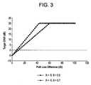
- FIG. 3illustrates a graph of the target SINR versus path loss for first and second example sets of intercept parameter and the fairness parameter
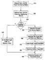
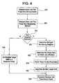
- FIG. 4illustrates a flow chart of the process performed by a UE in determining the transmit power spectral density according to an embodiment of the present invention
- FIG. 5illustrates the performance of the power control schemes for the assumptions listed in Table 1 below, presented as cell edge rate (defined as the 5% CDF user throughput) vs. average cell throughput.
- Example embodiments of the present inventionwill be described with respect to the UMTS system illustrated in FIG. 1 . However, it will be understood that the present invention is not limited to this system or to UMTS systems.
- FIG. 2illustrates an example where a UE may cause interference in a neighboring cell/sector (hereinafter collectively referred to as a cell).
- UE T 1is served by Node-B 1 and generates interference to Node-B 2 .
- UE T 1has a strong shadow fade to Node-B 2
- Another exampleis the case of a non-homogeneous deployment in which Node-B 2 has a much larger cell radius, in which case UE T 1 should be allowed to transmit at higher power levels.
- the open loop fractional power control methodmay be modified as follows: the target SINR may be set as a function of the path loss difference between the serving cell/serving Node B and the strongest neighbor cell/neighbor Node B.
- the target SINRmay be set as a function of the path loss difference between the serving cell/serving Node B and the strongest neighbor cell/neighbor Node B.
- PathLoss_Diff_dB10*log 10 (DL —Rx _PilotPower_ServingCell/ DL —Rx _PilotPower_StrongestNeighborCell) (5) where DL_Rx_PilotPower_ServingCell is the received downlink pilot power from the serving Node B and DL_Rx_PilotPower_StrongestNeighborCell is the received downlink pilot power from the strongest neighbor Node B.
- PPRdownlink pilot power ratio
- the positive slope parameter Bspecifies how quickly the target SINR increases as the UE moves towards the cell interior, and hence controls the fairness of the power control scheme.
- Max_Target_SINR_dBis the maximum allowable target SINR.
- FIG. 3illustrates a graph of the target SINR versus path loss for first and second example sets of intercept parameter A and the fairness parameter B.
- FIG. 3is an illustration of increasing target SINR as the path loss difference between the serving cell and the strongest non-serving cell increases (i.e., as the UE moves towards the interior of the cell).
- FIG. 3includes a first curve represented by diamonds for when the intercept parameter is ⁇ 5 and the fairness parameter is 0.5, and includes a second curve represented by squares for when the intercept parameter is ⁇ 5 and the fairness parameter is 0.7.
- larger values of the fairness parameter Bare more aggressive at increasing the target SINR for high geometry users.
- FIG. 4illustrates a flow chart of the process performed by a UE in determining the transmit power spectral density level, which will also be referred to herein as the reverse link power.
- the UEmeasures the received downlink pilot power from the current serving station (e.g., the Node B currently handing the communication needs of the UE). Often times, this is expressed as measuring the received downlink pilot power from the serving sector or cell. This measurement may be made on the order of every 100 ms-200 ms, and the received pilot power will be averaged over this interval so as to average out the affects of fast fading.
- the current serving statione.g., the Node B currently handing the communication needs of the UE.
- thisis expressed as measuring the received downlink pilot power from the serving sector or cell. This measurement may be made on the order of every 100 ms-200 ms, and the received pilot power will be averaged over this interval so as to average out the affects of fast fading.
- step S 20the UE measures the received downlink pilot power from any other neighboring station (e.g., Node Bs with coverage areas (cell or sector) adjacent to the serving Node B) within its receiving range. Often times, this is expressed as measuring the received downlink pilot power from the neighboring sector or cell. This measurement may be made on the order of every 100 ms-200 ms, and the received pilot power will be averaged over this interval so as to average out the affects of fast fading.
- any other neighboring statione.g., Node Bs with coverage areas (cell or sector) adjacent to the serving Node B
- thisis expressed as measuring the received downlink pilot power from the neighboring sector or cell. This measurement may be made on the order of every 100 ms-200 ms, and the received pilot power will be averaged over this interval so as to average out the affects of fast fading.
- PPRpilot power ratio
- the serving stationbroadcasts fractional power control parameters A, B, uplink interference, and Max_Target_SINR_dB on a broadcast channel such that all UEs being served by this station can decode the parameters. Accordingly, in step S 70 , the UE obtains these values. However, it will be appreciated the obtaining these values may occur before the process or concurrently with any step of the process.
- step S 80the UE computes the modified target SINR according to expression (5).
- HARQ RTT5 ms
- Num HARQ Processes10 Reuse scheme Reuse-1, no fractional frequency reuse or interference avoidance applied
- Schedulingis frequency selective based on uplink CQI pilot, only localized subcarrier allocations are used without any frequency hopping.
- FIG. 5illustrates the performance of the power control schemes for the assumptions listed in Table 1, presented as cell edge rate (defined as the 5% CDF user throughput) vs. average cell throughput. Note that the performance of fractional power control significantly improves by making use of the difference in path loss from the serving cell to the strongest neighbor cell, as compared to the case of using only the path loss to the serving cell alone. That is, for a given cell edge rate, a higher cell throughput can be obtained; or for a given cell throughput, a higher cell edge rate can be obtained.
- Open loop fractional power control using the path loss difference between the serving cell and the strongest neighbor cellprovides significantly improved performance as compared to using the path loss from the serving cell alone
Landscapes
- Engineering & Computer Science (AREA)
- Computer Networks & Wireless Communication (AREA)
- Signal Processing (AREA)
- Mobile Radio Communication Systems (AREA)
- Cable Transmission Systems, Equalization Of Radio And Reduction Of Echo (AREA)
Abstract
Description
TxPSD_dBm=min(Max—TxPSD_dBm, Target—SINR_dB+PathLoss_dB+UL_Interference_dBm) (1)
where
- Max_TxPSD_dBm is the maximum UE transmit power spectral density (power per tone), which is a function of the UE power class and the assigned transmission bandwidth (for example, the 21 dBm UE power class assigned a single resource unit of 12 subcarriers will have a maximum transmit power per tone of 10.21 dBm);
- UL_Interference_dBm is the reverse or uplink interference measured by a Node B serving the UE (typically, this the Node B determines this as total received energy minus the energy received from UEs being served by the Node B), and is reported to the UE, for example, over a control channel;
- PathLoss_dB is the path loss between the Node B and the UE; and
- Target_SINR_dB is the target signal-to-noise ratio (SINR) per antenna per tone. The fractional power control scheme available in the literature sets the target SINR to be a function of the path loss to the serving cell as follows:
Target—SINR_dB=A+(B−1)*(PathLoss_dB) (2) - where A and B are design parameters. Ignoring the Max_TxPSD_dBm limitation in (1), the UE transmit power spectral density is given by:
TxPSD_dBm=A+B*PathLoss_dB+UL_Interference_dBm (3)
Note that if B=0, there is no compensation for the path loss and all UEs transmit with the same transmit power spectral density (possible maximum power), which results in high interference levels and poor cell edge performance. If B=1, this is traditional slow power control in which the path loss is fully compensated and all UEs are received with the same SINR. This results in poor spectral efficiency. By setting 0<B<1, only a fraction of the path loss is compensated, which provides flexibility in balancing spectral efficiency and cell edge performance.
Modified_Target—SINR_dB=min(A+B*(PathLoss_Diff_dB), Max_Target—SINR_dB) (4)
where PathLoss_Diff_dB is the difference in path loss (including shadowing) between the strongest neighbor Node B and the current serving Node B. This measurement may easily be made by determining the ratio of the received downlink pilot power measurements as follows:
PathLoss_Diff_dB=10*log10(DL—Rx_PilotPower_ServingCell/ DL—Rx_PilotPower_StrongestNeighborCell) (5)
where DL_Rx_PilotPower_ServingCell is the received downlink pilot power from the serving Node B and DL_Rx_PilotPower_StrongestNeighborCell is the received downlink pilot power from the strongest neighbor Node B. The quantity in parenthesis is simply referred to as the downlink pilot power ratio (PPR). In equation (4), the intercept parameter A specifies the target SINR at the “cell edge” (i.e., when PathLoss_Diff_dB=0). The positive slope parameter B specifies how quickly the target SINR increases as the UE moves towards the cell interior, and hence controls the fairness of the power control scheme. Max_Target_SINR_dB is the maximum allowable target SINR.
Tx—PSD_dBm=min(Max—Tx—PSD_dBm, Modified_Target_SINR_dB+PathLoss_dB+UL_Interference_dBm) (6)
where PathLoss_dB is the measured path loss to the serving station as in expression (1).
| TABLE 1 |
| System Simulation Assumptions |
| Parameter | Assumption. |
| 5 MHz FDD | |
| Cellular Layout | Hexagonal grid, 19 cell sites, |
| 3 sectors per site | |
| Inter-site distance | 2500 meters |
| Losses (cable loss, body loss, etc.) | 7 dB |
| Distance-dependent path loss | COST 231 HATA model |
| L = 139.6 + 35.7log10(.R), | |
| R in kilometers | |
| Lognormal Shadowing | Similar to UMTS 30.03, B 1.4.1.4 |
| Shadowing standard deviation | 8 dB |
| Correlation distance of Shadowing | 50 m |
| Shadowing | Between cells | 0.5 |
| correlation | Between sectors | 1.0 |


Claims (12)
target SINR=min(A+B*(PathLoss_Diff), Max_Target_SINR)
Priority Applications (5)
| Application Number | Priority Date | Filing Date | Title |
|---|---|---|---|
| US11/650,984US7917164B2 (en) | 2007-01-09 | 2007-01-09 | Reverse link power control |
| PCT/US2008/000188WO2008085936A2 (en) | 2007-01-09 | 2008-01-07 | Reverse link power control |
| CN200880001878XACN101584129B (en) | 2007-01-09 | 2008-01-07 | Reverse link power control |
| JP2009545574AJP5281017B2 (en) | 2007-01-09 | 2008-01-07 | Uplink power control |
| EP08713028.2AEP2102996B1 (en) | 2007-01-09 | 2008-01-07 | Reverse link power control |
Applications Claiming Priority (1)
| Application Number | Priority Date | Filing Date | Title |
|---|---|---|---|
| US11/650,984US7917164B2 (en) | 2007-01-09 | 2007-01-09 | Reverse link power control |
Publications (2)
| Publication Number | Publication Date |
|---|---|
| US20080166976A1 US20080166976A1 (en) | 2008-07-10 |
| US7917164B2true US7917164B2 (en) | 2011-03-29 |
Family
ID=39496027
Family Applications (1)
| Application Number | Title | Priority Date | Filing Date |
|---|---|---|---|
| US11/650,984Expired - Fee RelatedUS7917164B2 (en) | 2007-01-09 | 2007-01-09 | Reverse link power control |
Country Status (5)
| Country | Link |
|---|---|
| US (1) | US7917164B2 (en) |
| EP (1) | EP2102996B1 (en) |
| JP (1) | JP5281017B2 (en) |
| CN (1) | CN101584129B (en) |
| WO (1) | WO2008085936A2 (en) |
Cited By (12)
| Publication number | Priority date | Publication date | Assignee | Title |
|---|---|---|---|---|
| US20090042593A1 (en)* | 2007-08-10 | 2009-02-12 | Qualcomm Incorporated | Adaptation of transmit power for neighboring nodes |
| US20100056041A1 (en)* | 2006-07-27 | 2010-03-04 | Jorg Huschke | Hierarchical broadcast transmission via multiple transmitters |
| US20100203917A1 (en)* | 2009-02-09 | 2010-08-12 | Rongzhen Yang | Techniques to determine transmitter power |
| US20110032908A1 (en)* | 2008-01-22 | 2011-02-10 | Telefonaktiebolaget L M Ericsson | Method, computer program, receiver, and apparatus for determining a channel quality index |
| US20110110257A1 (en)* | 2008-07-08 | 2011-05-12 | Dong Cheol Kim | Uplink transmission power control method in a wireless communication system |
| US20110117953A1 (en)* | 2008-07-08 | 2011-05-19 | Dong Cheol Kim | Method of controlling uplink power in wireless communication system |
| US20120127933A1 (en)* | 2010-11-02 | 2012-05-24 | Alcatel-Lucent Telecom Ltd. | Methods Of Setting Maximum Output Power For User Equipment And Reporting Power Headroom, And The User Equipment |
| US20130107751A1 (en)* | 2010-07-07 | 2013-05-02 | Ntt Docomo, Inc. | Base station and method |
| US20130215784A1 (en)* | 2010-11-10 | 2013-08-22 | Telefonaktiebolaget L M Ericsson (Publ) | Radio Base Station and a Method Therein |
| US20130265968A1 (en)* | 2008-02-01 | 2013-10-10 | Qualcomm Incorporated | Interference mitigation for control channels in a wireless communication network |
| US8995388B2 (en) | 2012-01-19 | 2015-03-31 | Futurewei Technologies, Inc. | Systems and methods for uplink resource allocation |
| US10359497B1 (en)* | 2016-04-07 | 2019-07-23 | Sprint Communications Company L.P. | Directional antenna orientation optimization |
Families Citing this family (63)
| Publication number | Priority date | Publication date | Assignee | Title |
|---|---|---|---|---|
| US6807405B1 (en) | 1999-04-28 | 2004-10-19 | Isco International, Inc. | Method and a device for maintaining the performance quality of a code-division multiple access system in the presence of narrow band interference |
| US7594151B2 (en)* | 2004-06-18 | 2009-09-22 | Qualcomm, Incorporated | Reverse link power control in an orthogonal system |
| US8452316B2 (en) | 2004-06-18 | 2013-05-28 | Qualcomm Incorporated | Power control for a wireless communication system utilizing orthogonal multiplexing |
| US7197692B2 (en)* | 2004-06-18 | 2007-03-27 | Qualcomm Incorporated | Robust erasure detection and erasure-rate-based closed loop power control |
| US8848574B2 (en) | 2005-03-15 | 2014-09-30 | Qualcomm Incorporated | Interference control in a wireless communication system |
| US8942639B2 (en) | 2005-03-15 | 2015-01-27 | Qualcomm Incorporated | Interference control in a wireless communication system |
| US8712422B1 (en) | 2005-05-18 | 2014-04-29 | Sprint Spectrum L.P. | Dynamic allocation of access channels based on access channel occupancy in a cellular wireless communication system |
| US8929908B2 (en) | 2005-10-27 | 2015-01-06 | Qualcomm Incorporated | Method and apparatus for estimating reverse link loading in a wireless communication system |
| US8442572B2 (en)* | 2006-09-08 | 2013-05-14 | Qualcomm Incorporated | Method and apparatus for adjustments for delta-based power control in wireless communication systems |
| US8670777B2 (en) | 2006-09-08 | 2014-03-11 | Qualcomm Incorporated | Method and apparatus for fast other sector interference (OSI) adjustment |
| US20080117849A1 (en)* | 2006-09-08 | 2008-05-22 | Qualcomm Incorporated | Method and apparatus for interaction of fast other sector interference (osi) with slow osi |
| US7711057B2 (en)* | 2007-01-17 | 2010-05-04 | C & P Technologies, Inc. | Apparatus and method for providing energy—bandwidth tradeoff and waveform design in interference and noise |
| US7720132B2 (en)* | 2007-01-17 | 2010-05-18 | C&P Technologies, Inc. | Energy—bandwidth tradeoff and transmit waveform design using interference and noise whitening method |
| EP2127163B1 (en)* | 2007-03-26 | 2015-07-22 | Telefonaktiebolaget LM Ericsson (publ) | A method and a device for finding imperfections in an rf path |
| US7970361B2 (en)* | 2007-11-28 | 2011-06-28 | Telefonaktiebolaget L M Ericsson (Publ) | Frequency band recognition methods and apparatus |
| US8385483B2 (en) | 2008-11-11 | 2013-02-26 | Isco International, Llc | Self-adaptive digital RF bandpass and bandstop filter architecture |
| US8588178B2 (en)* | 2009-03-19 | 2013-11-19 | Qualcomm Incorporated | Adaptive association and joint association and resource partitioning in a wireless communication network |
| WO2010108329A1 (en)* | 2009-03-27 | 2010-09-30 | 华为技术有限公司 | Method and device for performing emission power control in multi-carrier system |
| EP2282591B1 (en)* | 2009-07-01 | 2012-09-12 | Ntt Docomo, Inc. | Mobile and base station transceiver apparatus for communicating |
| US8331937B2 (en)* | 2009-08-17 | 2012-12-11 | Motorola Mobility Llc | Mitigation of uplink interference from wireless communication device connected to a micro cell |
| US8422956B2 (en)* | 2009-08-17 | 2013-04-16 | Motorola Mobility Llc | Mitigation of uplink interference from wireless communication device connected to micro cell |
| US8340593B2 (en)* | 2009-11-10 | 2012-12-25 | Intel Corporation | Techniques to control uplink power |
| CN102076062B (en)* | 2009-11-20 | 2015-03-11 | 华为技术有限公司 | Uplink transmit power control parameter acquisition method, eNodeB and user equipment |
| US9031599B2 (en)* | 2009-12-08 | 2015-05-12 | Futurewei Technologies, Inc. | System and method for power control |
| US8515474B2 (en)* | 2010-01-20 | 2013-08-20 | Futurewei Technologies, Inc. | System and method for scheduling users on a wireless network |
| US8437794B2 (en)* | 2010-01-28 | 2013-05-07 | Alcatel Lucent | Methods of determining uplink target signal-to-interfence-and-noise ratios and systems thereof |
| RU2523688C2 (en)* | 2010-04-09 | 2014-07-20 | Телефонактиеболагет Л М Эрикссон (Пабл) | Method and device in wireless network for determining uplink received power target value |
| US9002397B2 (en)* | 2010-06-29 | 2015-04-07 | Qualcomm Incorporated | Method and apparatus for device transmit power capping in wireless communications |
| JP5427139B2 (en) | 2010-07-29 | 2014-02-26 | 株式会社日立製作所 | Base station and cellular radio communication system |
| WO2012060746A1 (en)* | 2010-11-02 | 2012-05-10 | Telefonaktiebolaget L M Ericsson (Publ) | Method for uplink fractional transmit power control |
| CN102143568B (en)* | 2010-11-26 | 2015-02-04 | 华为技术有限公司 | Power control method and base station |
| US9420543B2 (en)* | 2010-12-10 | 2016-08-16 | Qualcomm Incorporated | Control of transmission power on high-speed dedicated physical control channel |
| CN102573028A (en)* | 2010-12-16 | 2012-07-11 | 中兴通讯股份有限公司 | Open loop power controlling method and system |
| CN102056178B (en)* | 2011-01-17 | 2013-08-21 | 新邮通信设备有限公司 | Interference coordination method among cells and a basestation |
| WO2012101482A1 (en)* | 2011-01-26 | 2012-08-02 | Nokia Corporation | Apparatus and method for allocating communication resources in a communication system |
| US9554338B2 (en)* | 2011-02-18 | 2017-01-24 | Qualcomm Incorporated | Apparatus, method, and system for uplink control channel reception in a heterogeneous wireless communication network |
| EP2693666A4 (en)* | 2011-03-30 | 2014-10-22 | Nec Casio Mobile Comm Ltd | Receiving device, receiving method, and computer program |
| EP2693812A4 (en)* | 2011-03-31 | 2014-12-17 | Beijing Nufront Mobile Multimedia Tech Co Ltd | Method and device for open loop uplink access power control |
| KR20140002043A (en)* | 2011-04-15 | 2014-01-07 | 알까뗄 루슨트 | Method and device for controlling uplink power |
| CN102811478B (en)* | 2011-05-31 | 2016-03-30 | 华为技术有限公司 | A kind of path loss compensation method and base station and subscriber equipment |
| US9414327B2 (en)* | 2011-06-06 | 2016-08-09 | Alcatel Lucent | Method and apparatus of fractional power control in wireless communication networks |
| CN102958146B (en) | 2011-08-17 | 2016-08-10 | 华为技术有限公司 | Method and terminal for terminal to transmit uplink signal |
| US9338807B2 (en)* | 2012-03-19 | 2016-05-10 | Futurewei Technologies, Inc. | System and method for direct mobile communications power control |
| CN104871612A (en)* | 2012-12-19 | 2015-08-26 | 富士通株式会社 | Wireless communication method, wireless communication system, wireless station, and wireless terminal |
| US9319916B2 (en) | 2013-03-15 | 2016-04-19 | Isco International, Llc | Method and appartus for signal interference processing |
| WO2014172897A1 (en)* | 2013-04-26 | 2014-10-30 | 上海贝尔股份有限公司 | Method and apparatus for uplink fractional power control based on interference |
| CN104219750B (en)* | 2013-06-03 | 2018-03-23 | 普天信息技术研究院有限公司 | A kind of close-loop power controlling method |
| CN104349437B (en)* | 2013-08-09 | 2018-10-19 | 上海诺基亚贝尔股份有限公司 | Method for inhibiting interference and user equipment |
| US9756577B2 (en)* | 2013-08-29 | 2017-09-05 | Airbus Ds Sas | Method for defining parameter values for controlling the transmission power of a piece of user equipment |
| CN105766032B (en)* | 2013-11-14 | 2019-05-28 | 华为技术有限公司 | Method and node in a wireless communication network |
| US9585103B2 (en)* | 2014-01-30 | 2017-02-28 | Qualcomm Incorporated | Techniques for controlling transmission power in shared radio frequency spectrum |
| CN103945513B (en)* | 2014-04-01 | 2018-06-01 | 大唐移动通信设备有限公司 | Poewr control method and device |
| US9794888B2 (en) | 2014-05-05 | 2017-10-17 | Isco International, Llc | Method and apparatus for increasing performance of a communication link of a communication node |
| CN104168635B (en)* | 2014-08-05 | 2018-05-01 | 大唐移动通信设备有限公司 | A kind of ascending power control method and device |
| WO2016039674A1 (en)* | 2014-09-10 | 2016-03-17 | Telefonaktiebolaget L M Ericsson (Publ) | Method and network node for obtaining nominal power and pathloss compensation factor of a power control process |
| EP3651386B1 (en) | 2015-05-04 | 2023-08-23 | ISCO International, LLC | Method and apparatus for increasing the performance of communication paths for communication nodes |
| WO2017210056A1 (en) | 2016-06-01 | 2017-12-07 | Isco International, Llc | Method and apparatus for performing signal conditioning to mitigate interference detected in a communication system |
| CN107623942B (en)* | 2016-07-14 | 2022-06-17 | 中兴通讯股份有限公司 | Upstream power adjustment method and device |
| CN107682922B (en)* | 2016-08-01 | 2021-01-05 | 中国电信股份有限公司 | Method and system for determining uplink signal interference noise ratio target value |
| US10298279B2 (en) | 2017-04-05 | 2019-05-21 | Isco International, Llc | Method and apparatus for increasing performance of communication paths for communication nodes |
| US10284313B2 (en) | 2017-08-09 | 2019-05-07 | Isco International, Llc | Method and apparatus for monitoring, detecting, testing, diagnosing and/or mitigating interference in a communication system |
| US10812121B2 (en) | 2017-08-09 | 2020-10-20 | Isco International, Llc | Method and apparatus for detecting and analyzing passive intermodulation interference in a communication system |
| US12127135B2 (en)* | 2021-04-05 | 2024-10-22 | Ntt Docomo, Inc. | Data-driven uplink power control in a wireless network |
Citations (17)
| Publication number | Priority date | Publication date | Assignee | Title |
|---|---|---|---|---|
| US20020077138A1 (en)* | 1999-03-15 | 2002-06-20 | Gunnar Bark | Adaptive power control in a radio communications systems |
| WO2003067783A2 (en) | 2002-02-07 | 2003-08-14 | Qualcomm Incorporated | Power control of serving and non-serving base stations |
| US20040005906A1 (en)* | 2001-07-24 | 2004-01-08 | Yukihiko Okumura | Transmission power control apparatus and method in a mobile communication system, mobile station, and communication apparatus |
| US20060025080A1 (en)* | 2004-08-02 | 2006-02-02 | Ilan Sutskover | Method and apparatus to vary power level of training signal |
| US20060183495A1 (en) | 2005-02-17 | 2006-08-17 | Soliman Samir S | System and method for global power control |
| US20060209767A1 (en)* | 2005-02-16 | 2006-09-21 | Samsung Electronics Co., Ltd. | System and method for controlling uplink traffic load in a cellular wireless mobile communication system |
| US20070129094A1 (en)* | 2005-12-07 | 2007-06-07 | Su-Ryong Jeong | Power control apparatus and method of time division duplex (TDD) telecommunication system |
| US20070201405A1 (en)* | 2006-02-27 | 2007-08-30 | Santhanam Arvind V | Power control in communication systems |
| US20080008113A1 (en)* | 2006-07-04 | 2008-01-10 | Samsung Electronics Co., Ltd. | Control system and method in a communication system |
| US20080068981A1 (en)* | 2006-09-14 | 2008-03-20 | Interdigital Technology Corporation | Wireless communication method and apparatus for assigning cell and resource blocks |
| US20080188260A1 (en)* | 2007-02-02 | 2008-08-07 | Motorola, Inc. | Method and apparatus for uplink power control in a communication system |
| US20080233995A1 (en)* | 2001-08-20 | 2008-09-25 | Shiu Da-Shan | Power control for a channel with multiple formats in a communication system |
| US20080261645A1 (en)* | 2006-11-01 | 2008-10-23 | Xiliang Luo | Interference and power control for wireless communication |
| US20090010242A1 (en)* | 2002-08-02 | 2009-01-08 | Leung Kin K | System and method for estimating interference in a packet-based wireless network |
| US20090143070A1 (en)* | 2005-01-20 | 2009-06-04 | Kodo Shu | Supporting an Allocation of Radio Resources |
| US20090154425A1 (en)* | 2007-12-13 | 2009-06-18 | Qualcomm Incorporated | METHODS AND APPARATUS FOR MAKING HANDOFF DECISIONS IN ACCESS TERMINALS CAPABLE OF OPERATING AT DIFFERENT TIMES IN BEST EFFORT AND QoS MODES OF TRAFFIC OPERATION |
| US20090227261A1 (en)* | 2006-07-07 | 2009-09-10 | Nokia Corporation | Radio resource allocation mechanism |
Family Cites Families (2)
| Publication number | Priority date | Publication date | Assignee | Title |
|---|---|---|---|---|
| US5491837A (en)* | 1994-03-07 | 1996-02-13 | Ericsson Inc. | Method and system for channel allocation using power control and mobile-assisted handover measurements |
| JP4343917B2 (en)* | 2001-07-24 | 2009-10-14 | 株式会社エヌ・ティ・ティ・ドコモ | Transmission power control apparatus and method, mobile station and communication apparatus in mobile communication system |
- 2007
- 2007-01-09USUS11/650,984patent/US7917164B2/ennot_activeExpired - Fee Related
- 2008
- 2008-01-07WOPCT/US2008/000188patent/WO2008085936A2/enactiveApplication Filing
- 2008-01-07JPJP2009545574Apatent/JP5281017B2/ennot_activeExpired - Fee Related
- 2008-01-07EPEP08713028.2Apatent/EP2102996B1/ennot_activeNot-in-force
- 2008-01-07CNCN200880001878XApatent/CN101584129B/ennot_activeExpired - Fee Related
Patent Citations (18)
| Publication number | Priority date | Publication date | Assignee | Title |
|---|---|---|---|---|
| US20020077138A1 (en)* | 1999-03-15 | 2002-06-20 | Gunnar Bark | Adaptive power control in a radio communications systems |
| US20040005906A1 (en)* | 2001-07-24 | 2004-01-08 | Yukihiko Okumura | Transmission power control apparatus and method in a mobile communication system, mobile station, and communication apparatus |
| US20070129096A1 (en)* | 2001-07-24 | 2007-06-07 | Ntt Docomo, Inc. | Transmission power control device and method, mobile station, and communication device in mobile communication system |
| US20080233995A1 (en)* | 2001-08-20 | 2008-09-25 | Shiu Da-Shan | Power control for a channel with multiple formats in a communication system |
| WO2003067783A2 (en) | 2002-02-07 | 2003-08-14 | Qualcomm Incorporated | Power control of serving and non-serving base stations |
| US20090010242A1 (en)* | 2002-08-02 | 2009-01-08 | Leung Kin K | System and method for estimating interference in a packet-based wireless network |
| US20060025080A1 (en)* | 2004-08-02 | 2006-02-02 | Ilan Sutskover | Method and apparatus to vary power level of training signal |
| US20090143070A1 (en)* | 2005-01-20 | 2009-06-04 | Kodo Shu | Supporting an Allocation of Radio Resources |
| US20060209767A1 (en)* | 2005-02-16 | 2006-09-21 | Samsung Electronics Co., Ltd. | System and method for controlling uplink traffic load in a cellular wireless mobile communication system |
| US20060183495A1 (en) | 2005-02-17 | 2006-08-17 | Soliman Samir S | System and method for global power control |
| US20070129094A1 (en)* | 2005-12-07 | 2007-06-07 | Su-Ryong Jeong | Power control apparatus and method of time division duplex (TDD) telecommunication system |
| US20070201405A1 (en)* | 2006-02-27 | 2007-08-30 | Santhanam Arvind V | Power control in communication systems |
| US20080008113A1 (en)* | 2006-07-04 | 2008-01-10 | Samsung Electronics Co., Ltd. | Control system and method in a communication system |
| US20090227261A1 (en)* | 2006-07-07 | 2009-09-10 | Nokia Corporation | Radio resource allocation mechanism |
| US20080068981A1 (en)* | 2006-09-14 | 2008-03-20 | Interdigital Technology Corporation | Wireless communication method and apparatus for assigning cell and resource blocks |
| US20080261645A1 (en)* | 2006-11-01 | 2008-10-23 | Xiliang Luo | Interference and power control for wireless communication |
| US20080188260A1 (en)* | 2007-02-02 | 2008-08-07 | Motorola, Inc. | Method and apparatus for uplink power control in a communication system |
| US20090154425A1 (en)* | 2007-12-13 | 2009-06-18 | Qualcomm Incorporated | METHODS AND APPARATUS FOR MAKING HANDOFF DECISIONS IN ACCESS TERMINALS CAPABLE OF OPERATING AT DIFFERENT TIMES IN BEST EFFORT AND QoS MODES OF TRAFFIC OPERATION |
Non-Patent Citations (2)
| Title |
|---|
| "Universal Mobile Telecommunications System (UMTS); Radio Resource Control (RRC); Protocol Specification (3GPP TS 25.331 Version 7.3.0 Release 7); ETSI TS 125 331", ETSI Standards, LIS, col. 3-R2, No. 7.3.0, Dec. 1, 2006, XP014040018, ISSN: 0000-0001, p. 248-252. |
| Texas Instruments, "A Method for Uplink Open Loop Power Control Based on Signal Strength Measurements from Multiple Cells/Sectors", 3GPP TSG RAN WG1 Meeting #46, No. R1-062018, Aug. 28, 2006, Sep. 1, 2006, pp. 1-7, XP002485109, Tallinn, Estonia, Retrieved from the Internet: URL:http://www.3gpp.org/ftp/tsg-ran?WG1-RL1/TSGR1-46/Docs/>the whole document. |
Cited By (28)
| Publication number | Priority date | Publication date | Assignee | Title |
|---|---|---|---|---|
| US20100056041A1 (en)* | 2006-07-27 | 2010-03-04 | Jorg Huschke | Hierarchical broadcast transmission via multiple transmitters |
| US8781391B2 (en)* | 2006-07-27 | 2014-07-15 | Telefonaktiebolaget Lm Ericsson | Hierarchical broadcast transmission via multiple transmitters |
| US8909279B2 (en) | 2007-08-10 | 2014-12-09 | Qualcomm Incorporated | Adaptation of transmit power for neighboring nodes |
| US20090042596A1 (en)* | 2007-08-10 | 2009-02-12 | Qualcomm Incorporated | Adaptation of transmit power based on channel quality |
| US20090042594A1 (en)* | 2007-08-10 | 2009-02-12 | Qualcomm Incorporated | Adaptation of transmit power based on maximum received signal strength |
| US20090042595A1 (en)* | 2007-08-10 | 2009-02-12 | Qualcomm Incorporated | Autonomous adaptation of transmit power |
| US8700083B2 (en) | 2007-08-10 | 2014-04-15 | Qualcomm Incorporated | Adaptation of transmit power based on maximum received signal strength |
| US8712461B2 (en) | 2007-08-10 | 2014-04-29 | Qualcomm Incorporated | Autonomous adaptation of transmit power |
| US20090042593A1 (en)* | 2007-08-10 | 2009-02-12 | Qualcomm Incorporated | Adaptation of transmit power for neighboring nodes |
| US9491722B2 (en)* | 2007-08-10 | 2016-11-08 | Qualcomm Incorporated | Adaptation of transmit power based on channel quality |
| US20110032908A1 (en)* | 2008-01-22 | 2011-02-10 | Telefonaktiebolaget L M Ericsson | Method, computer program, receiver, and apparatus for determining a channel quality index |
| US8929343B2 (en)* | 2008-01-22 | 2015-01-06 | Telefonaktiebolaget L M Ericsson (Publ) | Method, computer program, receiver, and apparatus for determining a channel quality index |
| US20130265968A1 (en)* | 2008-02-01 | 2013-10-10 | Qualcomm Incorporated | Interference mitigation for control channels in a wireless communication network |
| US9648596B2 (en)* | 2008-02-01 | 2017-05-09 | Qualcomm Incorporated | Interference mitigation for control channels in a wireless communication network |
| US20110110257A1 (en)* | 2008-07-08 | 2011-05-12 | Dong Cheol Kim | Uplink transmission power control method in a wireless communication system |
| US20110117953A1 (en)* | 2008-07-08 | 2011-05-19 | Dong Cheol Kim | Method of controlling uplink power in wireless communication system |
| US20110116408A1 (en)* | 2008-07-08 | 2011-05-19 | Dong Cheol Kim | Substrate conveying device |
| US8531975B2 (en)* | 2008-07-08 | 2013-09-10 | Lg Electronics Inc. | Method and apparatus for controlling uplink power in a wireless communication system |
| US8359059B2 (en) | 2008-07-08 | 2013-01-22 | Lg Electronics Inc. | Method of controlling uplink power in wireless communication system |
| US20110134759A1 (en)* | 2008-07-08 | 2011-06-09 | Dong Cheol Kim | Method and apparatus for controlling uplink power in a wireless communication system |
| US20100203917A1 (en)* | 2009-02-09 | 2010-08-12 | Rongzhen Yang | Techniques to determine transmitter power |
| US20130107751A1 (en)* | 2010-07-07 | 2013-05-02 | Ntt Docomo, Inc. | Base station and method |
| US20120127933A1 (en)* | 2010-11-02 | 2012-05-24 | Alcatel-Lucent Telecom Ltd. | Methods Of Setting Maximum Output Power For User Equipment And Reporting Power Headroom, And The User Equipment |
| US9055544B2 (en)* | 2010-11-02 | 2015-06-09 | Alcatel Lucent | Methods of setting maximum output power for user equipment and reporting power headroom, and the user equipment |
| US9445424B2 (en)* | 2010-11-10 | 2016-09-13 | Telefonaktiebolaget Lm Ericsson (Publ) | Radio base station and method for scheduling radio resources for user equipment |
| US20130215784A1 (en)* | 2010-11-10 | 2013-08-22 | Telefonaktiebolaget L M Ericsson (Publ) | Radio Base Station and a Method Therein |
| US8995388B2 (en) | 2012-01-19 | 2015-03-31 | Futurewei Technologies, Inc. | Systems and methods for uplink resource allocation |
| US10359497B1 (en)* | 2016-04-07 | 2019-07-23 | Sprint Communications Company L.P. | Directional antenna orientation optimization |
Also Published As
| Publication number | Publication date |
|---|---|
| WO2008085936A3 (en) | 2008-09-12 |
| EP2102996B1 (en) | 2013-11-27 |
| CN101584129B (en) | 2013-03-27 |
| US20080166976A1 (en) | 2008-07-10 |
| JP5281017B2 (en) | 2013-09-04 |
| WO2008085936A2 (en) | 2008-07-17 |
| JP2010516184A (en) | 2010-05-13 |
| EP2102996A2 (en) | 2009-09-23 |
| CN101584129A (en) | 2009-11-18 |
Similar Documents
| Publication | Publication Date | Title |
|---|---|---|
| US7917164B2 (en) | Reverse link power control | |
| Simonsson et al. | Uplink power control in LTE-overview and performance, subtitle: principles and benefits of utilizing rather than compensating for SINR variations | |
| CN102348266B (en) | Base station and cellular wireless communication system | |
| US9467864B2 (en) | Method and apparatus of spectrum utilization in a wireless cellular environment | |
| EP2359619B1 (en) | Method and apparatus of communication | |
| KR101718088B1 (en) | Method and apparatus for power control and load balancing based on load estimation of neighbor cell in wireless communication system | |
| KR101358142B1 (en) | Methods of determining uplink target signal-to-interference-and-noise ratios and systems thereof | |
| US20130242744A1 (en) | Signalling for Interference Management in HETNETs | |
| KR20110134588A (en) | Communication method of macro base station, small base station and terminal in hierarchical cell | |
| EP2991413A1 (en) | Method and apparatus for uplink fractional power control based on interference | |
| JP2012507219A (en) | Enhanced uplink power control based on interference management and transmission quality control | |
| CN101094015B (en) | Method for controlling initial emission power in open loop in mobile communication system | |
| KR101162972B1 (en) | Reverse link power control | |
| Safjan et al. | Automatic methods for HetNet uplink power control optimization under fractional load | |
| Castro-Hernandez et al. | A distributed load balancing algorithm for LTE/LTE-A heterogeneous networks | |
| Turkka et al. | Performance of LTE SON uplink load balancing in non-regular network | |
| Cîrstea et al. | LTE Uplink Power Control and its Impact on System Performance | |
| KR20120087423A (en) | Methods and apparatus for controlling interference based on information exchange between base stations in communication system | |
| Klein et al. | Potential of intra-LTE, intra-frequency load balancing | |
| CN102595582A (en) | Method and system for controlling uplink transmitting power of terminal | |
| Agrawal et al. | Interference penalty algorithm (IPA) for inter-cell interference co-ordination in LTE uplink | |
| Lalam et al. | Adaptive downlink power control for HSDPA femtocells | |
| Ali et al. | Cell edge detection based interference avoidance scheme for closed mode lte femtocells | |
| Aberra | Performance Evaluation of 6-Sector Site and Small Cell for Addis Ababa UMTS Deployment Scenario | |
| Danburam et al. | Analysis on energy efficient traffic load balancing in downlink LTE-advance heterogeneous network |
Legal Events
| Date | Code | Title | Description |
|---|---|---|---|
| AS | Assignment | Owner name:LUCENT TECHNOLOGIES INC., NEW JERSEY Free format text:ASSIGNMENT OF ASSIGNORS INTEREST;ASSIGNOR:RAO, ANIL M.;REEL/FRAME:019226/0869 Effective date:20070402 | |
| FEPP | Fee payment procedure | Free format text:PAYOR NUMBER ASSIGNED (ORIGINAL EVENT CODE: ASPN); ENTITY STATUS OF PATENT OWNER: LARGE ENTITY | |
| AS | Assignment | Owner name:ALCATEL-LUCENT USA INC., NEW JERSEY Free format text:MERGER;ASSIGNOR:LUCENT TECHNOLOGIES INC.;REEL/FRAME:025836/0834 Effective date:20081101 | |
| STCF | Information on status: patent grant | Free format text:PATENTED CASE | |
| AS | Assignment | Owner name:CREDIT SUISSE AG, NEW YORK Free format text:SECURITY INTEREST;ASSIGNOR:ALCATEL-LUCENT USA INC.;REEL/FRAME:030510/0627 Effective date:20130130 | |
| FPAY | Fee payment | Year of fee payment:4 | |
| AS | Assignment | Owner name:ALCATEL-LUCENT USA INC., NEW JERSEY Free format text:RELEASE BY SECURED PARTY;ASSIGNOR:CREDIT SUISSE AG;REEL/FRAME:033950/0261 Effective date:20140819 | |
| MAFP | Maintenance fee payment | Free format text:PAYMENT OF MAINTENANCE FEE, 8TH YEAR, LARGE ENTITY (ORIGINAL EVENT CODE: M1552); ENTITY STATUS OF PATENT OWNER: LARGE ENTITY Year of fee payment:8 | |
| FEPP | Fee payment procedure | Free format text:MAINTENANCE FEE REMINDER MAILED (ORIGINAL EVENT CODE: REM.); ENTITY STATUS OF PATENT OWNER: LARGE ENTITY | |
| LAPS | Lapse for failure to pay maintenance fees | Free format text:PATENT EXPIRED FOR FAILURE TO PAY MAINTENANCE FEES (ORIGINAL EVENT CODE: EXP.); ENTITY STATUS OF PATENT OWNER: LARGE ENTITY | |
| STCH | Information on status: patent discontinuation | Free format text:PATENT EXPIRED DUE TO NONPAYMENT OF MAINTENANCE FEES UNDER 37 CFR 1.362 | |
| FP | Lapsed due to failure to pay maintenance fee | Effective date:20230329 |